Page 1
FACT SHEET
(Pursuant to Nevada Administrative Code (NAC) 445A.401)
Permittee Name: Nevada Gold Mines LLC
Project Name: AA Block Project
Permit Number: NEV0090060 Review Type/Year/Revision: Renewal 2020, Fact Sheet Revision 00
A. Location and General Description of Facility
Location:
The AA Block is a portion of the Nevada Gold Mines Goldstrike facilities located
in the Little Boulder Basin adjacent to the Tuscarora Mountain Range on the county
line between Elko and Eureka Counties, approximately 27 miles northwest of the
community of Carlin, Nevada. The facilities are located in Sections 23, 24, 25, 26,
27, 34, 35, and 36, Township 36 North (T36N), Range 49 East (R49E), and Sections
19, 20, 28, 29, and 30, T36N, R50E, Mount Diablo Baseline & Meridian.
The AA Block encompasses an area of approximately 2,854 acres. The private
lands, approximately 2,591 acres, are owned or controlled by Nevada Gold Mines
LLC (Permittee) and the unpatented mining claims, approximately 263 acres, are
held by Permittee on U.S. Bureau of Land Management administered lands.
The Goldstrike facilities can be accessed from Interstate 80 via the Carlin exit, Exit
280 and traveling northwest on the Nevada State Route SR766 for approximately
27 miles.
General Description:
This site is in permanent closure. The AA Block currently consists of the AA Block
Heap Leach Facility (AA Block HLF, which includes AA, Phases I, II, III, and
IIIA), AA Barren Solution Pond, one pumpback well, numerous groundwater
monitoring wells, the AA Tailings Impoundment, AA Tails Seepage Collection
Pond, Mill 4 Tailings Storage Facility 1 (Mill 4) and Seepage Collection Pond, and
the Bazza Waste Rock Disposal Facility (WRDF). With the closure of the heap
leach pad, most of the adsorption, desorption, recovery (ADR) process components
have been dismantled, and the buildings converted into a metallurgical testing lab.
B. Synopsis
Water Pollution Control Permit (WPCP) NEV0090060 (Permit) was first issued to
Barrick Goldstrike Mines, Inc. and became effective 3 August 1991. The Permit
was renewed in 1997, 2007, 2013, 2018, and 2020.
Page 2
Nevada Gold Mines LLC
AA Block Project
Permit No. NEV0090060 (Renewal 2020, Fact Sheet Rev. 00)
Page 2 of 25
20201005km_0090060_NOD_FactSheet_Rev00.docx
In 2008, the AA Block WPCP was reorganized along with the North Block WPCP
(NEV0091029) such that active mine components were consolidated into
NEV0091029 while components in closure or projected to be in closure in the near
future were consolidated into NEV0090060. The following components were
transferred to NEV0091029 during this process:
o AA Barren Solution Pond,
o Wet Mill/Autoclave Process Facilities,
o Valdez Pond,
o Autoclave Stockpile Pads,
o AA Block Carbon Reactivation Facilities.
Historical information and past test results for these components may be found in
previous Permit documents and reports for NEV0090060.
In July 2019, Nevada Gold Mines LLC (NGML), a joint venture between Barrick
Gold Corporation and Newmont Goldcorp Corporation was created. NGML
represents the combination of various Nevada operations, of which the AA Block
Project is included. Revision 01 of the 2018 Permit reflects the transfer of the
Permit from Barrick Goldstrike Mines Inc. to NGML.
In February 2020, the Permittee submitted a document entitled Final Plans for
Permanent Closure (FPPC) of the AA Block Project. As the AA Block Project
represents components that are either in closure or projected to be in closure in the
near future, the FPPC represents a compilation of previously submitted FPPCs.
This FPPC has been reviewed and was approved by the Division in August 2020.
This FPPC includes the following facilities:
o AA Heap Leach Pad
AA, Phase I, II, III, & IIIA Heap Leach Pads
o AA Tailings Storage Facility
o AA Seepage Collection Pond
o LPOP-10 and other monitoring ports
o AA Pump-back Well and Piping
o Mill 4 Tailings Storage Facility 1
Mill4 Seepage Collection Pond, pumps, sumps, valves, ditches,
pipelines
o Other associated Pipes, Valves, and Piping
In May 2020, at the request of the Division, the Permittee submitted an engineering
design change (EDC) to transfer the AA Barren Solution Pond (aka Lab Pond) from
the NEV0091029 Permit back to the NEV0090060 Permit. Transfer of the pond
was to satisfy the BMRR Closure Branch policy of having a draindown collection
pond uniquely associated with a process component, specifically the AA HLF.
Page 3
Nevada Gold Mines LLC
AA Block Project
Permit No. NEV0090060 (Renewal 2020, Fact Sheet Rev. 00)
Page 3 of 25
20201005km_0090060_NOD_FactSheet_Rev00.docx
AA Block Heap Leach Facility (AA Block HLF which includes AA Pad, Phases
I, II, III, and IIIA)
The AA Block HLF is one large heap leach pad segmented into five component
leaching areas: the AA Pad (2.2 million sq.ft.); the Phase I Pad (1.9 million sq.ft.);
the Phase II Pad (1.2 million sq.ft.); the Phase III Pad (2.6 million sq.ft.); and the
Phase IIIA Pad (1.8 million sq.ft.), resulting in a total area of 9.7 million sq.ft.
(approximately 223 acres).
Leach ore was primarily hauled directly from the Betze-Post Pit to the leach pads
as run-of-mine for leaching. However, a portion of the ore was crushed and
agglomerated with lime and cement prior to placement on the AA Pad.
The original AA Pad was lined with a single 60-mil High Density Polyethylene
(HDPE) liner over compacted soil. The Phases I and II leach pad expansions were
lined with 80-mil HDPE over a prepared base of compacted, in-place soil meeting
a permeability specification of 1.0 x 10⁻⁶ centimeters per second (cm/sec). The
Phase III leach pad expansion was lined with 80-mil Very Low Density
Polyethylene (VLDPE) which overlays a minimum thickness of 12 inches of
compacted soil meeting a permeability specification of 1.0 x 10⁻⁶ cm/sec. A sand
leak detection layer incorporating an electronic leak detection system exists
between the synthetic liner and compacted soil layers of the Phase III expansion.
The Phase IIIA leach pad expansion was lined with 80-mil VLDPE, over a
secondary liner consisting of a minimum thickness of 12 inches of compacted soil
meeting a permeability specification of 1.0 x 10⁻⁶ cm/sec. A sand leak detection
layer incorporating an electronic leak detection system exists below this compacted
soil layer. The sand layer in turn overlies a lower liner consisting of a minimum
thickness of 12 inches of compacted soil meeting a permeability specification of
1.0 x 10⁻⁶ cm/sec. Table 1 provides a description of the liner materials utilized for
the various AA Leach Pad and subsequent expansions.
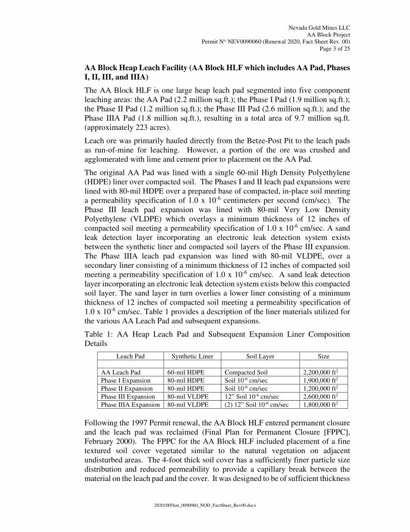
Table 1: AA Heap Leach Pad and Subsequent Expansion Liner Composition
Details
Leach Pad Synthetic Liner Soil Layer Size
AA Leach Pad 60-mil HDPE Compacted Soil 2,200,000 ft2
Phase I Expansion 80-mil HDPE Soil 10-6 cm/sec 1,900,000 ft2
Phase II Expansion 80-mil HDPE Soil 10-6 cm/sec 1,200,000 ft2
Phase III Expansion 80-mil VLDPE 12” Soil 10-6 cm/sec 2,600,000 ft2
Phase IIIA Expansion 80-mil VLDPE (2) 12” Soil 10-6 cm/sec 1,800,000 ft2
Following the 1997 Permit renewal, the AA Block HLF entered permanent closure
and the leach pad was reclaimed (Final Plan for Permanent Closure [FPPC],
February 2000). The FPPC for the AA Block HLF included placement of a fine
textured soil cover vegetated similar to the natural vegetation on adjacent
undisturbed areas. The 4-foot thick soil cover has a sufficiently finer particle size
distribution and reduced permeability to provide a capillary break between the
material on the leach pad and the cover. It was designed to be of sufficient thickness
Page 4
Nevada Gold Mines LLC
AA Block Project
Permit No. NEV0090060 (Renewal 2020, Fact Sheet Rev. 00)
Page 4 of 25
20201005km_0090060_NOD_FactSheet_Rev00.docx
to store water during the period of maximum precipitation for elimination by
evaporation and transpiration during periods of minimum precipitation.
Reclamation plans included reshaping to provide natural morphology, eliminate the
potential for ponding water, provide a natural looking and naturally functioning
drainage network and reduce erosion and sediment yield from the surface of the
cover to levels comparable to the existing natural landforms of the area. The cover
and drainage network are also designed to minimize the risk of a localized breach
of the cover and exposure of the underlying spent ore material. The stormwater
drainage system around the perimeter of the re-contoured heap leach pad has been
redesigned to safely accept the additional stormwater runoff from the covered leach
pad area.
One-dimensional and two-dimensional hydrologic models indicate that the
percolation rate through the covered AA Block HLF is small because precipitation
is significantly less than potential evaporation in the region. Based on the analyses
performed, a 4-foot cover thickness was selected as the optimum cover design. A
4-foot thick capillary/evapotranspiration (ET) cover constructed of Carlin
Formation siltstones effectively minimizes water percolating through the
recontoured AA Block HLF. The ET cover is expected to be stable under all
conditions anticipated in the proposed re-contouring design. The design also
incorporates a high transmissivity toe drain beneath the ET cover to convey
draindown and/or post-closure flow to the existing downgradient AA ponds.
Toe Drain
As described above, the ET cover was designed for minimal flux of precipitation
through the ET cover. Nonetheless, a high transmissivity toe drain was incorporated
beneath the ET cover, located along the downgradient (western) margins of the
heap, and conveys any potential draindown or post-closure flows that may drain
through the spent heap material to the AA ponds. The toe drain-flow is collected
in a sump consisting of a minimum 22-cubic feet of non-calcareous drain rock
encapsulated in filter fabric, with an 8-inch diameter perforated drainpipe. The
sump is designed for a flow rate up to of 710 gallons per minute (gpm); as of the
fourth quarter 2017, the current draindown rate ranges between 4 – 6 gpm. This
toe drain flow represents the heap draindown and correlates well with the modeled
draindown rate.
Water Balance Model and Results
In order to design a capillary cover for the AA Block HLF, hydrologic simulations
(modeling) were conducted. The daily evapotranspiration data along with the daily
potential soil evaporation and precipitation were used to develop a spreadsheet
model to simulate water fluxes through soil layers covered with vegetation
according to a seed mix developed for the site. The model was run to study water
fluxes under developing vegetative cover, in dry and wet years and under varying
soil thicknesses.
Page 5
Nevada Gold Mines LLC
AA Block Project
Permit No. NEV0090060 (Renewal 2020, Fact Sheet Rev. 00)
Page 5 of 25
20201005km_0090060_NOD_FactSheet_Rev00.docx
The water balance model was run for local area conditions and configured with two
back-to-back wet years. The spreadsheet model determined a cover thickness of 3
feet would be adequate to prevent deep percolation after the effective vegetation
cover reached about 33% (year 4), with percolation (leakage through cover) of 2.82
inches (37 gpm) in year 1. If cover thickness were increased to 4 feet, the leakage
potential decreased to 0.49 inches (7 gpm) in year 1. The use of a 5-foot cover
thickness eliminated the leakage potential in year 1 but provided no benefit beyond
the second year. Based on the marginal reduction in flux, the 4-foot cover thickness
was selected as the optimum cover thickness.
Draindown Solution Management
Draindown solution from the AA Pad flows to the AA Barren Pond. Solutions from
the Phase I, II, III, and IIIA (Phase) leach pads, Leach Pad Observation Port
(LPOP)-10 (pad leak detection) and the AA Pumpback Well (AA PBW) are
directed to the Phase Composite Box (PCB). The PCB is a double-containment
structure, with the manifold collection box primary containment being constructed
of mild steel, surrounded by a precast concrete box for secondary containment.
Solution return pipes from the AA Block HLF to the PCB and from the PCB to the
AA Barren Pond are buried pipe-in-pipe. Any leakage occurring from the AA
Block HLF pipe reports to the PCB primary containment box, whereas leakage
from the PCB outlet pipe reports to the AA Barren Pond.
The Permittee submitted a plan, which was subsequently approved by the Nevada
Division of Environmental Protection (Division) in November 2013, to construct
an ore stockpile on the northwestern portion of the HLP. The stockpile is located
approximately 100 yards from LPOP-10. During 2014, flows to LPOP-10
temporarily increased from approximately 5 gallons per day (gpd) to 155 gpd. With
this flow increase, certain constituents of concern, i.e. pH, arsenic, magnesium,
manganese, nitrate, selenium, sulfate, and total dissolved solids, also increased.
Due to the increased flow rate, the Permittee increased monitoring frequency to
monthly, which continued through the fourth quarter of 2014 following a noticeable
decrease in flow rate. In general, the flows have decreased, having a yearly average
of approximately 1.75 gpd in 2019.
Monitoring:
The following sections describe the monitoring of heap draindown, leach pad leak
detection, and site groundwater.
Draindown
The PCB secondary containment is monitored weekly for fluid accumulation and
reported as average daily accumulation in gallons per day (Permit monitoring point
PCB). Discrete flow rate measurements and water quality samples are collected
for LPOP-10, AA PBW, and the co-mingled Phase solutions.
Due to the location of the PCB, i.e., downgradient and associated with the AA HLP
stormwater diversion channel, the secondary containment would receive
Page 6
Nevada Gold Mines LLC
AA Block Project
Permit No. NEV0090060 (Renewal 2020, Fact Sheet Rev. 00)
Page 6 of 25
20201005km_0090060_NOD_FactSheet_Rev00.docx
stormwater flows, thereby resulting in occasional exceedances in the PCB leak
detection Permit limits. To alleviate this situation, the Permittee submitted an
Engineering Design Change (EDC) in August 2016 to reconstruct the lower portion
of the existing diversion resulting in essentially blocking the PCB with the channel
berm. The Division approved the EDC in October 2016. The improvements were
completed in April 2017.The AA Pad Inlet (AAPI) and Phase Composite (PC)
draindown flows are monitored individually at end-of-pipe for flow rate and water
quality as the solution enters the AA Barren Solution Pond.
Beginning in 2018, the PCB began to exceed the annual leak detection rate of 50
gpd as allowable per Part I.G.4 of the Permit. Ongoing investigation and evaluation
of the PCB line has resulted in a list of potential leak sources and repair approach
proposals. Although the Permittee has proactively investigated the leakage, the
Division has included a Schedule of Compliance item in the 2020 Permit renewal
to complete all investigations and repair/resolve the PCB leakage.
Leach Pad Observation Ports (LPOPs)
Leak detection systems for the AA and Phases I and II pads are provided by LPOPs
which were constructed to detect any solutions that may escape through the
synthetic liner.
LPOPs 6 and 8 are downgradient of the leach pad on the western toe of the AA pad.
LPOPs 9, 10, 11, and 12 are located on the western toe of the Phase pads on the
northern end of the facility. LPOPs are monitored weekly for fluid accumulation
and reported as average daily accumulation in gallons per day. As part of the
closure of Post Pad #1 and the construction of the Bazza WRDF, LPOPs 1 thru 5,
were either closed out or buried. LPOP-7 was abandoned during the closure of the
AA Block HLF.
The leak detection systems that are part of the Phases III and IIIA pad liners were
monitored with an Electronic Leak Detection System (ELDS), as well as physical
leak detection ports beneath the solution collection ditches. The ELDS was taken
out of service during closure of the AA Block HLF and has not been monitored
since that time.
Ground Water Observation Ports (GWOPs)
GWOPs are monitoring wells used to monitor groundwater elevation and quality in
the vicinity of the leach pads. GWOPs are monitored quarterly for Profile I
parameters. GWOPs 9 and 12 are located on the eastern side upgradient of the
Phase leach pads for establishing background groundwater quality. GWOP-13a is
located west of the Phase leach pads for monitoring downgradient groundwater
quality. GWOP-16b is downgradient of the solution ponds on the northwest side.
GWOP-17b is located upgradient of the remaining solution pond on the southeast
end to establish groundwater quality upgradient of the ponds. GWOPs 1 thru 4
were closed/buried during construction of the Bazza WRDF; GWOPs 5 through 8
and 14 were abandoned during closure of the AA Block HLF. There is no record
of GWOP-19 and it is believed it was never constructed and the number was simply
Page 7
Nevada Gold Mines LLC
AA Block Project
Permit No. NEV0090060 (Renewal 2020, Fact Sheet Rev. 00)
Page 7 of 25
20201005km_0090060_NOD_FactSheet_Rev00.docx
overlooked. GWOPs 10A, 11A, and 15A are associated with the AA Tailings
Impoundment.
Cutoff Trench
Cutoff Trench North Side (CTNS) and Cutoff Trench South Side (CTSS) were
constructed downgradient of the four phased leach pads during commissioning of
the Phase I ponds to intercept shallow groundwater drainage originating upgradient
of the leach pads. Each trench has a monitoring point (CTNS and CTSS) located
on the north and south ends, respectively, of the cutoff trench to monitor fluid flow
rate and, if present, water quality of that flow. To date, no solution from any source
has ever reported to these trenches.
LPOP-10 and Associated Corrective Action
In January 2008, the Permittee informed the Division that LPOP-10 had exceeded
the permitted average daily flow over the fourth quarter of 2007 of 75 gpd and the
permitted average daily flow for calendar year 2007 of 25 gpd. The Permittee
submitted a Corrective Action Plan (CAP) as required by the Division in February
2008. The CAP included the installation of a permanent pumping system in LPOP-
10 to minimize head on the secondary layer. The CAP also required installation
and monitoring of a new groundwater monitoring well (GWOP-18), located
immediately downgradient of LPOP-10.
In May 2008, the Permittee submitted an EDC for the construction of a double
contained (pipe-in-pipe) drain line to convey the solution from LPOP-10 to the
PCB. The EDC was approved by the Division and constructed, which allowed
continuous pumping of the fluid rather than periodic evacuation to a water truck.
In February 2009, the Division required submittal of a second CAP which was
approved by the Division in June 2009. The second CAP expanded the
groundwater investigation and included the addition of two new monitoring wells:
GWOP-20, installed near the existing GWOP-12 to provide additional upgradient
groundwater data, and GWOP-21, a vadose zone well, which was installed in
November 2009 near GWOP-18 but at a 45 degree angle to extend under the heap
leach pad. Soil samples taken during the drilling of GWOP-21 were used to
evaluate the vadose zone below LPOP-10 for evidence of leakage through the
LPOP-10 secondary layer.
The analyses of water sampled from GWOP-18 and GWOP-21 indicate the
presence of process solution derived exceedances, of Division Profile I reference
values, for arsenic, magnesium, manganese, nitrate, selenium, sulfate, and total
dissolved solids (TDS). As a result, a Finding of Alleged Violation and Order
(Order) was issued to the Permittee in April 2010. The Order required submittal of
a revised CAP which included the installation of AA PBW and an additional
downgradient monitoring well (GWOP-22).
AA PBW was constructed approximately 40 feet downgradient of GWOP-18 to a
depth of 215 feet and is screened over the interval from 155 feet to 215 feet (see
Page 8
Nevada Gold Mines LLC
AA Block Project
Permit No. NEV0090060 (Renewal 2020, Fact Sheet Rev. 00)
Page 8 of 25
20201005km_0090060_NOD_FactSheet_Rev00.docx
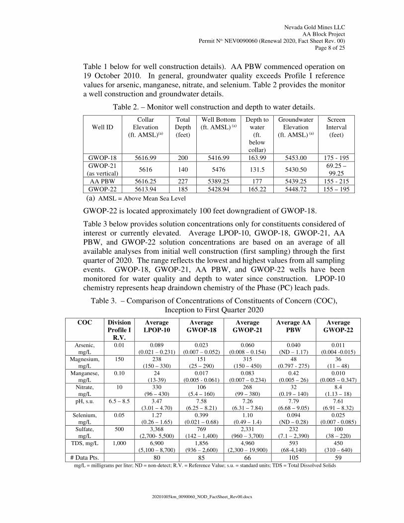
Table 1 below for well construction details). AA PBW commenced operation on
19 October 2010. In general, groundwater quality exceeds Profile I reference
values for arsenic, manganese, nitrate, and selenium. Table 2 provides the monitor
a well construction and groundwater details.
Table 2. – Monitor well construction and depth to water details.
Well ID
Collar
Elevation
(ft. AMSL)(a)
Total
Depth
(feet)
Well Bottom
(ft. AMSL) (a)
Depth to
water
(ft.
below
collar)
Groundwater
Elevation
(ft. AMSL) (a)
Screen
Interval
(feet)
GWOP-18 5616.99 200 5416.99 163.99 5453.00 175 - 195
GWOP-21
(as vertical) 5616 140 5476 131.5 5430.50
69.25 –
99.25
AA PBW 5616.25 227 5389.25 177 5439.25 155 - 215
GWOP-22 5613.94 185 5428.94 165.22 5448.72 155 – 195
(a) AMSL = Above Mean Sea Level
GWOP-22 is located approximately 100 feet downgradient of GWOP-18.
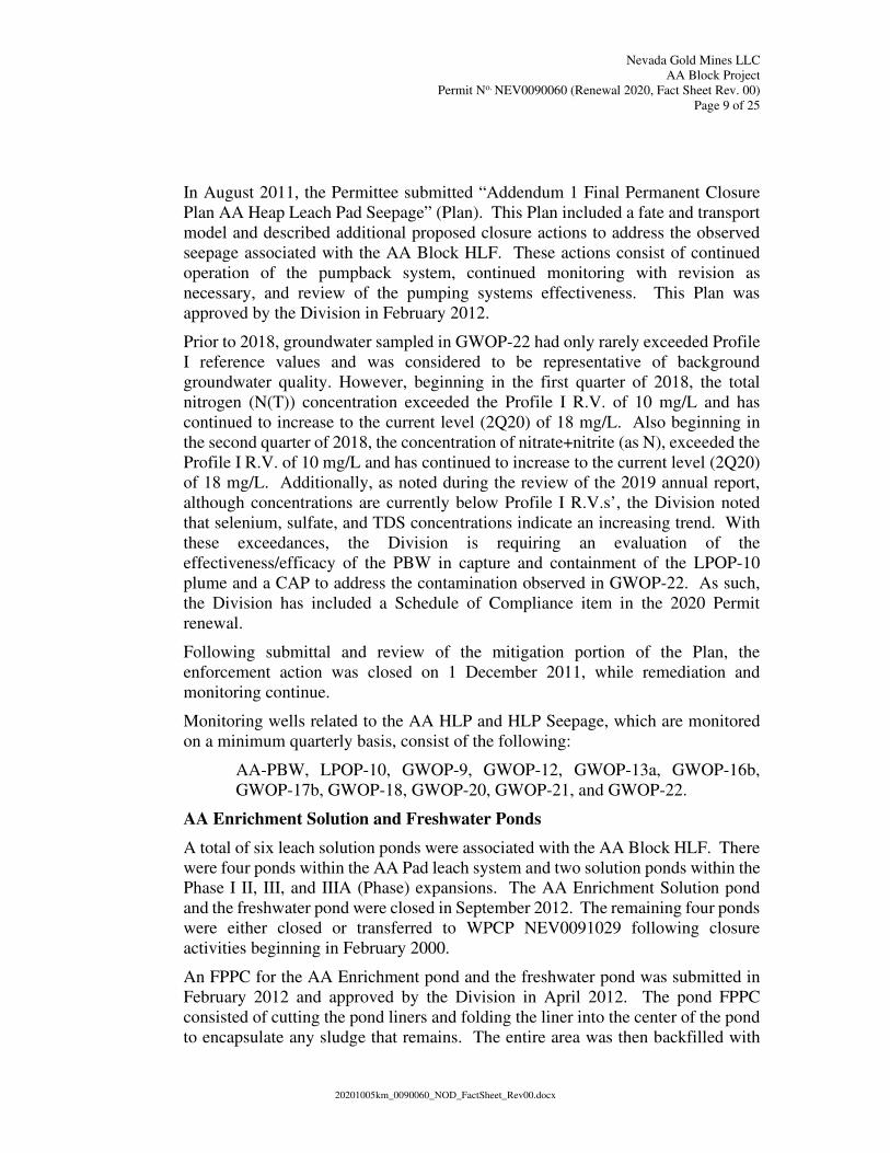
Table 3 below provides solution concentrations only for constituents considered of
interest or currently elevated. Average LPOP-10, GWOP-18, GWOP-21, AA
PBW, and GWOP-22 solution concentrations are based on an average of all
available analyses from initial well construction (first sampling) through the first
quarter of 2020. The range reflects the lowest and highest values from all sampling
events. GWOP-18, GWOP-21, AA PBW, and GWOP-22 wells have been
monitored for water quality and depth to water since construction. LPOP-10
chemistry represents heap draindown chemistry of the Phase (PC) leach pads.
Table 3. – Comparison of Concentrations of Constituents of Concern (COC),
Inception to First Quarter 2020
COC Division
Profile I
R.V.
Average
LPOP-10
Average
GWOP-18
Average
GWOP-21
Average AA
PBW
Average
GWOP-22
Arsenic,
mg/L
0.01 0.089
(0.021 – 0.231)
0.023
(0.007 – 0.052)
0.060
(0.008 – 0.154)
0.040
(ND – 1.17)
0.011
(0.004 -0.015)
Magnesium,
mg/L
150 238
(150 – 330)
151
(25 – 290)
315
(150 – 450)
48
(0.797 - 275)
36
(11 – 48)
Manganese,
mg/L
0.10 24
(13-39)
0.017
(0.005 - 0.061)
0.083
(0.007 – 0.234)
0.42
(0.005 – 26)
0.010
(0.005 – 0.347)
Nitrate,
mg/L
10 330
(96 – 430)
106
(5.4 – 160)
268
(99 – 380)
32
(0.19 – 140)
8.4
(1.13 – 18)
pH, s.u. 6.5 – 8.5 3.47
(3.01 – 4.70)
7.58
(6.25 – 8.21)
7.26
(6.31 – 7.84)
7.79
(6.68 – 9.05)
7.61
(6.91 – 8.32)
Selenium,
mg/L
0.05 1.27
(0.26 – 1.65)
0.399
(0.021 – 0.68)
1.10
(0.49 – 1.4)
0.094
(ND – 0.28)
0.025
(0.007 - 0.085)
Sulfate,
mg/L
500 3,368
(2,700- 5,500)
769
(142 – 1,400)
2,331
(960 – 3,700)
232
(7.1 – 2,390)
100
(38 – 220)
TDS, mg/L 1,000 6,900
(5,100 – 8,700)
1,856
(936 – 2,600)
4,960
(2,300 – 19,900)
593
(68-4,140)
450
(310 – 640)
# Data Pts. 80 85 66 105 59 mg/L = milligrams per liter; ND = non-detect; R.V. = Reference Value; s.u. = standard units; TDS = Total Dissolved Solids
Page 9
Nevada Gold Mines LLC
AA Block Project
Permit No. NEV0090060 (Renewal 2020, Fact Sheet Rev. 00)
Page 9 of 25
20201005km_0090060_NOD_FactSheet_Rev00.docx
In August 2011, the Permittee submitted “Addendum 1 Final Permanent Closure
Plan AA Heap Leach Pad Seepage” (Plan). This Plan included a fate and transport
model and described additional proposed closure actions to address the observed
seepage associated with the AA Block HLF. These actions consist of continued
operation of the pumpback system, continued monitoring with revision as
necessary, and review of the pumping systems effectiveness. This Plan was
approved by the Division in February 2012.
Prior to 2018, groundwater sampled in GWOP-22 had only rarely exceeded Profile
I reference values and was considered to be representative of background
groundwater quality. However, beginning in the first quarter of 2018, the total
nitrogen (N(T)) concentration exceeded the Profile I R.V. of 10 mg/L and has
continued to increase to the current level (2Q20) of 18 mg/L. Also beginning in
the second quarter of 2018, the concentration of nitrate+nitrite (as N), exceeded the
Profile I R.V. of 10 mg/L and has continued to increase to the current level (2Q20)
of 18 mg/L. Additionally, as noted during the review of the 2019 annual report,
although concentrations are currently below Profile I R.V.s’, the Division noted
that selenium, sulfate, and TDS concentrations indicate an increasing trend. With
these exceedances, the Division is requiring an evaluation of the
effectiveness/efficacy of the PBW in capture and containment of the LPOP-10
plume and a CAP to address the contamination observed in GWOP-22. As such,
the Division has included a Schedule of Compliance item in the 2020 Permit
renewal.
Following submittal and review of the mitigation portion of the Plan, the
enforcement action was closed on 1 December 2011, while remediation and
monitoring continue.
Monitoring wells related to the AA HLP and HLP Seepage, which are monitored
on a minimum quarterly basis, consist of the following:
AA-PBW, LPOP-10, GWOP-9, GWOP-12, GWOP-13a, GWOP-16b,
GWOP-17b, GWOP-18, GWOP-20, GWOP-21, and GWOP-22.
AA Enrichment Solution and Freshwater Ponds
A total of six leach solution ponds were associated with the AA Block HLF. There
were four ponds within the AA Pad leach system and two solution ponds within the
Phase I II, III, and IIIA (Phase) expansions. The AA Enrichment Solution pond
and the freshwater pond were closed in September 2012. The remaining four ponds
were either closed or transferred to WPCP NEV0091029 following closure
activities beginning in February 2000.
An FPPC for the AA Enrichment pond and the freshwater pond was submitted in
February 2012 and approved by the Division in April 2012. The pond FPPC
consisted of cutting the pond liners and folding the liner into the center of the pond
to encapsulate any sludge that remains. The entire area was then backfilled with
Page 10
Nevada Gold Mines LLC
AA Block Project
Permit No. NEV0090060 (Renewal 2020, Fact Sheet Rev. 00)
Page 10 of 25
20201005km_0090060_NOD_FactSheet_Rev00.docx
clean non-Potentially Acid Generating (non-PAG) waste material, compacted,
brought up to an elevation of 5,500 feet above mean sea level (AMSL), leveled,
and eventually utilized for parking. The closure of the ponds, with the exception
of backfilling to the 5,500 foot AMSL elevation, was completed in September 2012.
The AA Barren Solution Pond, per the March 2020 EDC, was transferred back from
the North Block Permit (NEV0091029) to the AA Block Permit and is now
uniquely associated with the AA HLF. The pond is double-lined, consisting of 80-
mil HDPE for both the primary and secondary liners, with a capacity of 2.5 million
gallons, and is being used as a temporary flow-through catchment for the current
4 - 6 gallons per minute (gpm) of AA Block HLF solution draindown. Draindown
solutions ultimately report to the process water system of the North Block
operations (WPCP NEV0091029). Draindown is expected to continue to decline
to less than 1 gpm by 2040. At that time, the pond will be converted to an
evaporation cell (E-Cell). A TPPC for the conversion/construction of an e-cell is
in progress and planned for submittal in the fourth quarter of 2020.
AA Tailings Impoundment
The Carbon-in-Leach (CIL) tailings slurry has been historically routed to the two
tailings impoundments - the AA Tailings Impoundment (AA Tails) and the North
Block Tailings Disposal Facility (NBTDF). Only the AA Tails is included in
WPCP NEV0090060. The NBDTF and Tailings Storage Facility 3 (TSF3) are
included in WPCP NEV0091029 and now receive all tailings produced.
Active tailings deposition ceased at the AA tailings storage facility (TSF) in 1997,
when the NBTDF was commissioned (except for a period in 2007 when tailings
were deposited to consume the remaining storage capacity). The AA Tails is lined
with native materials. In areas where the in-place soils have permeability greater
than 1 x 10⁻⁶ cm/sec, a 12-inch thick compacted clay liner (permeability <1 x 10⁻⁷
cm/sec) has been installed. A 1-foot thick sand/gravel blanket drain overlays all but
an approximately 80-foot wide strip along the upper reaches of the entire clay liner.
The clay liner is located in the deeper parts of the impoundment. A minimum of 2
feet of compacted material with a permeability of less than 1 x 10⁻⁵ cm/sec was
placed over the blanket to minimize the hydraulic head imposed on the drain. A
synthetic liner was placed over higher permeability zones within the north
embankment area.
In May/June 2014, during construction of the TCM Tailings Thickener,
containment of the AA Tails was breached by a power pole anchor and two
foundation drain pipes that collect non-contact subsurface water. Upon realization
of the breach, the Permittee requested a reduction of the AA Tails freeboard
reference elevation to 5718.5 feet AMSL. In November 2014, the Division
approved the Permittee request to a reduction in the AA Tails freeboard elevation.
In February 2015, the Permittee submitted an EDC to repair the liner damage and
reconstruct the drain sump to prevent the non-contact surface water from entering
the AA Tails. This EDC also provided for a future request to re-instate the
previously approved freeboard elevation for the potential future use of the AA Tails
Page 11
Nevada Gold Mines LLC
AA Block Project
Permit No. NEV0090060 (Renewal 2020, Fact Sheet Rev. 00)
Page 11 of 25
20201005km_0090060_NOD_FactSheet_Rev00.docx
for water storage due to operational issues with the TCM plant – this request was
denied by the Division based on the AA Tails not meeting pond design criteria per
NAC 445A.435.1, and because of degradation of groundwater at GWOP-10A and
GWOP-15A. Following denial of the request to increase freeboard elevation to
allow use of AA Tails for the TCM, a tentative plan for permanent closure (TPPC)
for the AA Tails was submitted in July 2015 and updated in December 2015.
GWOP-10A/GWOP-15A
Beginning in the second quarter of 2007, groundwater chemistry at GWOP-15A,
located on the southern edge of the impoundment, indicated trace weak acid
dissociable (WAD) cyanide, and elevated concentrations of sulfate and TDS.
Similar constituent exceedances were discovered in 1994 at GWOP-15 (which was
replaced by GWOP-15A in 2002). At that time, the Permittee conducted an
investigation consisting of installing seven new monitoring wells, data collection
and analysis, and performing a geological evaluation of the area. The investigation
concluded that excess water located in the southeast corner of the AA tails dam was
infiltrating into a contact zone between the Carlin Formation and the underlying
Vinini Formation allowing for a preferential flow path from the tails dam to
GWOP-15.
This investigation resulted in a plan to deposit tails in the southeast corner above
the contact zone to develop a protective beach sealing off the infiltration area and
confine the supernatant pond to the northeast quadrant of the tails. By 1998, water
levels in GWOP-15 had dropped, precluding a clean sampling zone due to
sedimentation close to the base of the well. GWOP-15 was closed and relocated to
its current location as GWOP-15A. Initial sampling conducted from the second
quarter of 2001 through the second quarter of 2002 (2Q01 thru 2Q02) indicated
decreasing levels of sulfate and TDS, suggesting that the plan was working.
However, beginning in the second quarter of 2007 and continuing through 2017,
both sulfate and TDS began to increase and have remained at relatively stable
levels, i.e. 1,300 mg/L sulfate and 2,200 mg/L TDS, respectively.
Also in the second quarter of 2007 and continuing through 2017, at GWOP-10A,
located downgradient of the impoundment, both sulfate and TDS concentrations
began to increase, and, in the first quarter of 2011, concentrations of both exceeded
the Division Profile I reference values. Trace WAD cyanide was also indicated.
In the first half of 2009, in correspondence to the Division, the Permittee theorized
that the chemistry trends were coincident with the supernatant pond approaching
the south and east embankments of the impoundment. In 2010, as an interim
stabilization measure to minimize solution impoundment in the southeast corner as
well as reduce the amount of windborne dust originating from the AA Tails surface,
the Permittee placed a nominal 2-foot thick cover of waste rock over the south and
east portion of the tailings beach. The Permittee believes that the placement of the
cover will aid in reversing the groundwater degradation.
Page 12
Nevada Gold Mines LLC
AA Block Project
Permit No. NEV0090060 (Renewal 2020, Fact Sheet Rev. 00)
Page 12 of 25
20201005km_0090060_NOD_FactSheet_Rev00.docx
Additionally, the Permittee has actively reduced the supernatant pond volume, with
only direct meteoric water collecting on the impoundment surface. In the short
term, the 2015 TPPC proposed to begin closure–related activities consisting of the
following steps:
o Removal of the water pool to allow stabilization of the tailings and facilitate
cover placement;
o Removal of the TCM construction laydown yard (completed January 2016);
o Design, permit and construction of new secondary containment for the RIL
tailings distribution, decant/reclaim return pipelines and the tails thickener
pipe corridor overflow which currently reports to the AA tailing storage
facility (AATSF) (WPCP NEV0091029);
o Design, permit, and construction of a location to run evaporators at TSF 3
(WPCP NEV0091029);
o Permit and construct a pad for disposal of spill related material on the North
Block Tails Dam (WPCP NEV0091029); and
o Development of an FPPC.
The long-term proposal included the following:
o Completion and submittal of an FPPC (completed July 2019);
o Formulation of a budget and commencing the budgeting process;
o Complete a schedule of work;
o Stockpile cover material (scheduled for 4Q2020); and
o Begin closure construction activities (1Q2021).
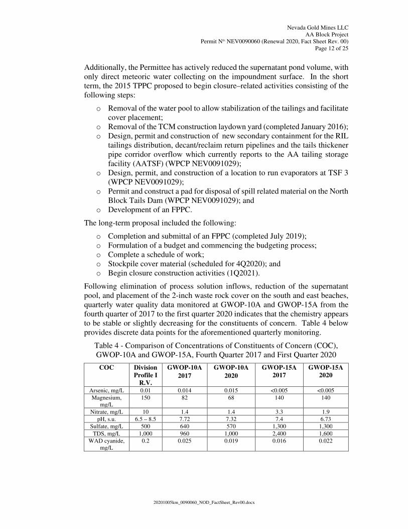
Following elimination of process solution inflows, reduction of the supernatant
pool, and placement of the 2-inch waste rock cover on the south and east beaches,
quarterly water quality data monitored at GWOP-10A and GWOP-15A from the
fourth quarter of 2017 to the first quarter 2020 indicates that the chemistry appears
to be stable or slightly decreasing for the constituents of concern. Table 4 below
provides discrete data points for the aforementioned quarterly monitoring.
Table 4 - Comparison of Concentrations of Constituents of Concern (COC),
GWOP-10A and GWOP-15A, Fourth Quarter 2017 and First Quarter 2020
COC Division
Profile I
R.V.
GWOP-10A
2017
GWOP-10A
2020
GWOP-15A
2017
GWOP-15A
2020
Arsenic, mg/L 0.01 0.014 0.015 <0.005 <0.005
Magnesium,
mg/L
150 82 68 140 140
Nitrate, mg/L 10 1.4 1.4 3.3 1.9
pH, s.u. 6.5 – 8.5 7.72 7.32 7.4 6.73
Sulfate, mg/L 500 640 570 1,300 1,300
TDS, mg/L 1,000 960 1,000 2,400 1,600
WAD cyanide,
mg/L
0.2 0.025 0.019 0.016 0.022
Page 13
Nevada Gold Mines LLC
AA Block Project
Permit No. NEV0090060 (Renewal 2020, Fact Sheet Rev. 00)
Page 13 of 25
20201005km_0090060_NOD_FactSheet_Rev00.docx
AA TSF Tentative and Final Plans for Permanent Closure
An updated TPPC was received in December 2015 and approved by the Division
in April 2016. The Permittee submitted an FPPC to the Division in June 2017. The
FPPC was revised and resubmitted in February 2018. The Division reviewed and
approved the revised FPPC in April 2018. In July 2019, the Permittee submitted
Revision 2 of the FPPC, which was subsequently was reviewed and approved by
the Division in March 2020.
AA Tails draindown, AA-TDD, which represents seepage from the tailings blanket
drain, embankment blanket drain, and embankment toe drain, currently reports to
the vault located above the Seepage Collection Pond (SCP) via a seepage collection
trench. Solution is currently pumped from the vault to the tailings surface via a 6-
inch diameter HDPE pipe. AA-TDD is sampled quarterly for NDEP Profile I and
flowrate at the vault. The 6-inch pipe extends up the downstream (west)
embankment face, under the AA TSF crest road, and terminates approximately 275
feet onto the tailings surface. Historic flows (2019) averaged approximately 23
gpm.
AA TDD will ultimately be managed by constructing a series of E-Cells in the
vicinity of the existing SCP, per the approved FPPC. In the interim, the permittee
was directed by the Division to end recirculation of the tailings draindown to the
AA TSF surface. Per a January 2020 approved EDC submitted for the North Block
Project (NEV0091029), the Permittee plans to tie the AA TSF seepage return pipe
into both of the two new reclaim pipes (primary and backup) that will convey
process water from the NBTDF to the Autoclave area Wet Mill in a pipe-in-pipe
arrangement. The NBTDF reclaim pipes will be contained in the RIL to CIL
Pipeline Corridor, which will entail utilizing existing lined corridors/facilities
where possible and constructing a new lined channel to connect the existing
containment areas. One-way check valves will be installed so reclaim water cannot
flow back into the seepage return pipe. Construction is due to be completed by
September 2020.
The approved FPPC includes regrading and covering the TSF with a minimum 4-
foot thick engineered soil cover. Beginning in 2020, the Permittee will begin an
accelerated schedule of waste rock cover placement to be completed in 2023 with
the final cover placement. Stormwater diversion channels will be constructed to
convey the 500-year 24-hour storm event converging in a spillway which outfalls
into the existing Brush Creek Diversion.
Approximately 3 acres of the AA Tails surface will be utilized for temporary
stockpiles of highly mineralized ore and magnetic separation concentrate. The
stockpiles will remain for approximately 5 years from initial placement of
material(s). The highly mineralized ore stockpile was constructed in January 2012
and decommissioned in January 2017. Prior to construction and loading of the
stockpile, two vibrating wire piezometers (VWP) monitoring points (AA-VWP-11-
01 and AA-VWP-11-02 in the Permit) were installed directly beneath the ore
stockpile footprint. The VWPs were installed a minimum of 6 feet deep in the base
Page 14
Nevada Gold Mines LLC
AA Block Project
Permit No. NEV0090060 (Renewal 2020, Fact Sheet Rev. 00)
Page 14 of 25
20201005km_0090060_NOD_FactSheet_Rev00.docx
tailing material. Following decommissioning of the Mineralized Ore Stockpile,
piezometers AA-VWP-11-01 and AA-VWP-11-02 were removed. Only stockpiled
cover material remains on the AA Tails surface.
AA Tails Seepage Collection Pond
The AA Tails Seepage Collection Pond is designed to collect seepage from the AA
Tails (AA – UCP) embankment drains. This pond is lined with 40-mil HDPE which
overlays a 12-inch layer of low-permeability clay and has a leak detection system.
This pond only contains solution during periods of heavy rainfall or power upsets.
The AA Tails Seepage Collection Pond also has the required capacity to contain
the 100-year, 24-hour storm event. As of August 2020, under normal operating
conditions, solution reporting from the embankment drains is pumped to the surface
of the AA Tails and represents the impounded tails draindown (reclaim) solution
(supernatant), AA-TR. However, pursuant to the January 2020 EDC submitted for
the North Block Project (NEV0091029) and described above, the Permittee plans
to eliminate recirculation of the draindown to the surface by tying the AA TSF
seepage return pipe into the process circuit for the North Block Project facilities
until such time as E-cell construction is completed in the vicinity of the SCP. AA-
TR will continue to be monitored semi-annually for Profile I and the depth of the
supernatant on the impoundment surface.
Solution Pond Observation Ports (SPOPs) are used to monitor the leak detection
systems in this collection pond. The SPOPs consist of 12 inches of coarse sand
between the synthetic liner and the low-permeability clay layer with a network of
perforated HDPE pipes draining to the east and west ends. SPOPs are monitored
using riser pipes located at the lower corners of each pond for the accumulation of
fluids and reported as an average daily accumulation.
SPOP-3 is located west of the AA Barren Solution Pond; SPOP-5 and SPOP-9 are
located south of the seepage collection pond and west of the AA Tails (downstream
toe of the embankment). GWOPs 10a and 11a are located downgradient (west) of
the AA Tails to monitor groundwater quality. GWOP-15a is on the southern end
of the tailings facility. These monitoring wells are monitored quarterly for Division
Profile I parameters and groundwater elevation.
SPOP-2 was abandoned as part of closure activities in 2012 related to the AA
Enrichment Solution and Freshwater Ponds. SPOPs 6 through 8 were abandoned
during the AA Facility HLF closure activities in 2000. SPOP-1 was abandoned
during closure of the Post Pad #1 in 1991. SPOP-4 was transferred to WPCP
NEV0091029 in 2008.
Mill 4 Facility
The original WPCP for the Mill 4 Facility (NEV0089015) was incorporated into
the Mill 4 Tailing Storage Facility 1 WPCP (NEV0092100) in June of 2001. The
Mill 4 Facilities were constructed during the period 1988-1989. The mill building,
a Caro’s Acid system, and all ancillary pipes, tanks, and valves were located within
secondary containment. All mill facilities have been closed and removed; the site
Page 15
Nevada Gold Mines LLC
AA Block Project
Permit No. NEV0090060 (Renewal 2020, Fact Sheet Rev. 00)
Page 15 of 25
20201005km_0090060_NOD_FactSheet_Rev00.docx
has been in post-closure monitoring since August 2004. Newmont Mining
Corporation sold the Mill 4 Facility and Mill 4 Tailings Storage Facility to the
Permittee in late 2005. The Permittee submitted an EDC in December 2009 for
transfer of these facilities from Permit NEV0092100 to Permit NEV0090060;
Permit transfer was completed in May 2010.
Mill 4 Tailings Storage Facility 1 (Mill 4 TSF1) and Seepage Collection Pond
Construction of Mill 4 TSF1 began 13 March 1989, and deposition of tailings began
1 June 1989. Although a pre-regulation facility, the design meets the applicable
requirements of the NAC 445A regulations for tailings storage facilities, including
the 12-inch thick low permeability soil layer (1 x 10⁻⁶ cm/sec maximum
permeability). Mill 4 TSF1was constructed over compacted low permeability soils
with draindown water being conveyed through an underdrain blanket to an
underdrain collection pond constructed with primary and secondary 80-mil HDPE
liners. A geonet between the liners provides a flow path to convey leakage to the
leak detection sump. Initially, the Mill 4 TSF1 starter embankment extended to an
elevation of 5,505 feet AMSL and was subsequently raised to 5,530 feet AMSL in
1990, and 5,559 feet AMSL in 1991. Mill 4 TSF1 covers approximately 102 acres
and contains some 12 million tons of material. The facility was used regularly for
tailings disposal until June 1993, after which its use was limited to brief periods
when required for maintenance of the Mill 4 Tailings Storage Facility 2 prior to the
acquisition of Mill 4 by the current Permittee.
The Mill 4 TSF1 embankment was constructed to withstand a 100-year, 24-hour
precipitation event with an initial upstream slope of 2.5H:1V (horizontal to vertical)
and an initial downstream slope of 2H:1V. This is an earth- and rock-fill structure
consisting of two zones, ‘A’ and ‘S’. Zone ‘A’, the retaining structure, was
constructed of random fill (mine waste material rock consisting of clayey silt to
fractured rock), delivered and compacted in 24-inch thick layers by haul trucks.
Zone ‘S’, the seal zone, on the upstream face, is constructed of quality-
assurance/quality-control (QA/QC)-documented, low permeability (1 x 10⁻⁶
cm/sec), fine-grained soils (silts and sandy silts) that were borrowed from within
the Mill 4 TSF1 basin area, moisture conditioned, bentonite- or clay-amended as
required, and compacted in nominal 12-inch thick lifts. Density and moisture tests
were performed by nuclear density and sand cone methods. Zone ‘S’ is 20 feet
wide and was extended a minimum 2 feet into low-permeability, over-consolidated
silts along the entire length of the embankment to form a cut-off trench. Zone ‘S’
was ultimately covered with a layer of 10-ounce geotextile to minimize erosion
prior to deposition of a protective layer of tailings material.
The tailings storage basin is covered with 12 inches of QA/QC-documented, low-
permeability (1 x 10⁻⁶ cm/sec), fine-grained soils borrowed from within the Mill 4
TSF1 basin area, moisture-conditioned, bentonite- or clay-amended as required,
and compacted to 95% modified Proctor density in nominal 6-inch thick lifts. The
area beneath the supernatant pond received 18 inches of the same low permeability
soil to further enhance containment. The entire prepared Mill 4 TSF1 basin is
Page 16
Nevada Gold Mines LLC
AA Block Project
Permit No. NEV0090060 (Renewal 2020, Fact Sheet Rev. 00)
Page 16 of 25
20201005km_0090060_NOD_FactSheet_Rev00.docx
covered with a nominal 12 inches of drainage blanket material containing 3.9-
12.7% minus 200-mesh fines. A network of 8-inch, 6-inch, and 4-inch diameter
corrugated polyethylene tube (CPT) underdrain pipe was installed within v-
trenches cut into the drainage blanket on 30-foot centers. A layer of 6-ounce
geotextile covers the drainage blanket in the supernatant pool area to prevent
migration of fines.
Draindown solution (UCP), currently flowing at less than 0.25 gpm, as of the
second quarter of 2020, reports to the Mill 4 Seepage Collection Pond (UCPRL)
and is pumped to the North Block seepage collection pond (WPCP NEV0091029).
The Mill 4 Seepage Collection Pond has an operating volume of 330,000 gallons
with 3 feet of freeboard and a total volume of 480,000 gallons. The seepage
collection pond base and embankment are constructed in a 2-foot-deep cut area
which was backfilled with waste rock and covered with fine-grained soils. The
base and embankments were moisture conditioned and compacted to a minimum
95% of maximum dry density prior to being covered with a layer of 6-ounce
geotextile. The geotextile was then covered with a 60-mil HDPE secondary liner,
overlain by geonet, which was in turn covered with a primary liner of 60-mil HDPE.
The interstitial geonet is hydraulically linked by a 6-inch diameter poly-vinyl
chloride (PVC) pipe to the external Leak Collection and Recovery System (LCRS)
sump, Underdrain Collection Pond Leak Detection Sump (UCPS), and equipped
with a submersible pump. Any fluid reporting to the sump is pumped back to the
UCPRL.
Groundwater quality in the area of Mill 4 TSF1 was monitored by upgradient wells
MW-8, MW-9D, and MW-9S. Downgradient monitoring wells included MW-1D,
MW-1S, MW-6, MW-7, MW-10, TB-5, and TB-9. As a result of the pit dewatering
program, all wells have been dry since at least June 2005. In March 2011, the
Permittee submitted an EDC for removal and abandonment of eight of the ten
monitoring wells: MW-1S, MW-6, MW-7, MW-9S, MW-9D, MW-10, TB-5, and
TB-9. The Division approved the EDC in May 2011; well abandonment was
completed in November 2011. Also in May 2011, monitor wells MW-8 and MW-
1D were formally transferred to WPCP NEV0091029. No direct monitoring of the
Mill 4 TSF1 groundwater wells will be performed in the AA Block Permit.
Monitoring is addressed in WPCP NEV0091029.
Fluid head pressures in the Mill 4 TSF1, which are to be maintained below an
average of 2 feet of hydraulic head, are measured by a network of vibrating wire
piezometers. Mill 4 TSF1 utilizes two underdrain piezometers (P2 and P5) and two
piezometers within the tailings solids (P3 and P4). All piezometer data indicate
stable head pressures at well below 2 feet.
An FPPC for Mill 4 TSF1 was submitted in December 2012 and approved by the
Division in February 2015. The FPPC consists of converting the existing open
pond into an evaporation cell (e-cell) and constructing an infiltration gallery
northwest of the e-cell to allow for a controlled discharge in the event of an
overflow.
Page 17
Nevada Gold Mines LLC
AA Block Project
Permit No. NEV0090060 (Renewal 2020, Fact Sheet Rev. 00)
Page 17 of 25
20201005km_0090060_NOD_FactSheet_Rev00.docx
In preparation for permanent closure of the Mill 4 TSF1 facility, in 2012 the
Permittee began stockpiling Carlin Formation (Carlin) materials from the Tailings
Storage Facility 3 (TSF3, WPCP NEV0091029) excavation on the surface of Mill
4 TSF1 for closure of the facility with a Carlin cap. This area will also be utilized
to temporarily stockpile additional colluvium and Carlin material that will be used
as buffer zone materials for the phased construction of TSF3 over the next few
years. The total area the stockpiles will encompass is approximately 14 acres.
The Permittee submitted plans to expand the existing stockpiles on Mil 4 TSF1 by
5.3 acres and 16.5 acres. The Division approved these expansions in June 2014 and
December 2014, respectively.
In June 2020, the Permittee submitted an EDC for a modification to the closure
spillway. The proposed modification modified the spillway design to ultimately
terminate outside the TSF3 haul road, flowing along the existing ground before
flowing by gravity to its discharge point in the Betze-Post Pit. Although the
Division is typically not receptive to storm event flows purposely being directed to
an open pit, as per NAC 445.429. 2, the alternate option of pumping from the
spillway outlet to access either Bell Creek or Rodeo Creek to route around the pit
has been demonstrated to be a much less desirable option and the Division
determined this alternative is not practical or in the best interest of a long-term
passive closure scenario. Therefore, discharge to the Betze-Post pit was approved
and applies only to the Mill 4 TSF closure spillway. (See correspondence entitled
Mill 4 TSF Closure Storm Water Management Options, dated 28 April 2016).
Based on its location relative to other existing process components and their
specific closure strategies, and the previous approval, the Division approved the
proposed spillway modifications in August 2020.
Mill 4 TSF1 is protected from storm run-on by a diversion berm placed between
the tailings embankment and Brush Creek.
Post Pad #1
Prior to construction of the Bazza WRDF, the Post Pad #1 heap leach facility was
operated by Western States Minerals in the approximate southeast corner of the
current Bazza location. The heap, which encompassed an area of approximately 19
acres, was operated from August 1986 to July 1989. The heap was detoxified using
sodium hypochlorite and hydrogen peroxide as rinse solution until the WAD
cyanide concentration was less than 0.2 mg/L.
Two process ponds were associated with this facility. The ponds were constructed
of 40-mil HDPE liner over a compacted low-permeability soil layer with a 6 inch
sand layer leak detection system. Draindown solution was transported by water
truck to the AA Tails for disposal. By the latter part of 1990, draindown flow had
decreased to almost zero. The ponds were permanently closed in 1991.
The Post Pad #1 was closed by the Permittee in 1991 and covered by construction
of the Bazza WRDF. Newmont acquired the effluent pipe discharge in a land
Page 18
Nevada Gold Mines LLC
AA Block Project
Permit No. NEV0090060 (Renewal 2020, Fact Sheet Rev. 00)
Page 18 of 25
20201005km_0090060_NOD_FactSheet_Rev00.docx
exchange with the Permittee in 1999 and assumed responsibility for management
of the Post Pad #1 draindown solution as part of its North Area Leach Permit WPCP
NEV0087065. Following the formation of the Nevada Gold Mines joint venture in
July 2019, the Permittee assumed responsibility for the permanent closure and
management of the draindown solution under WPCP NEV0087065. The Permittee
has constructed and is currently operating an evapotranspiration cell for long-term
solution management.
Bazza Waste Rock Disposal Facility
The Bazza WRDF has a surface area of approximately 2,500 acres and is located
west and southwest of the Betze-Post Pit. The Bazza WRDF received waste rock
from the Betze-Post Pit as well as minor amounts from the underground operations
at the Meikle and Rodeo Creek mines. The Bazza WRDF was designed and
operated to comply with applicable mining and reclamation requirements and to
prevent the degradation of waters of the State.
Beginning in the early 1990s, an in-pit geochemical testing and classification
program was initiated to facilitate selective handling of Potentially Acid-
Generating (PAG) and non-PAG waste rock. The program of waste rock
classification, segregation, and selective placement was designed to reduce the
occurrence of acid rock drainage and to prevent releases of surface runoff, seepage,
or infiltration that may have a potential to degrade waters of the State. The program
was based on data from more than 140 humidity cell tests on a variety of waste rock
types and static tests on over 30,000 composite exploration drill hole samples
within the Betze-Post Pit. Results from testing indicate a correlation between the
acid neutralization potential/acid generating potential (ANP/AGP) ratio, net
carbonate value (NCV), and sulfide sulfur. The results indicate that waste rock
having an ANP/AGP ratio greater than 1.2 will not produce acid, which is therefore
classified as non-PAG. Material with an ANP/AGP ratio less than 1.2 and with a
sulfide sulfur value greater than 0.3% is classified as PAG.
PAG and non-PAG waste rock disposal has been facilitated through computerized
truck dispatching, recording, and verification systems. Monitoring components
associated with waste rock management have included ongoing acid-base
accounting on waste rock samples collected from the mining operations and annual
composite samples of PAG and non-PAG material. Meteoric Water Mobility
Procedure (MWMP)-Profile I analyses have been performed annually on the
composite samples as well to further characterize the waste rock.
A conceptual closure design of the Bazza facility was included in the 2004 Waste
Rock Management Plan (WRMP) update. The Bazza WRDF FPPC, submitted in
March 2007, incorporates an ET cover into the design. Specifically, the 2007 FPPC
update included the following elements:
- Use of a layered cover comprised of topsoil and Carlin Formation
(Fm) materials designed to minimize or eliminate infiltration of
water and oxygen;
Page 19
Nevada Gold Mines LLC
AA Block Project
Permit No. NEV0090060 (Renewal 2020, Fact Sheet Rev. 00)
Page 19 of 25
20201005km_0090060_NOD_FactSheet_Rev00.docx
- A multi-layer cover consisting of 6 feet of Carlin Fm and topsoil
material to be placed over the approximately 498 acres of
encapsulated PAG cells;
- A minimum of 12 inches of cover consisting of either run-of-mine
Carlin Fm material or a combination of topsoil and Carlin Fm
material over the non-PAG remainder of the waste rock facility.
Results of modeling of the soil cover, based on the modeling code VADOSE/W
calibrated to the AA Block HLF cover, indicated that the proposed Bazza WRDF
soil cover would provide an effective barrier to movement of meteoric water into
PAG waste rock. Additionally, monitoring of the AA Block HLF cover over the
last approximately 12 years indicates that the cover is functioning as designed and
evaluation of available geologic materials indicates that this design approach can
be applied to the Bazza WRDF.
The Bazza WRDF reached the end of its operational life in 2009 and has since been
closed. Waste rock disposal has shifted to the Clydesdale Waste Rock Facility (a
component of WPCP NEV0091029).
Portions of the Bazza WRDF have been utilized for other mining related activities,
i.e., the bioremediation cell, several ore stockpiles, and replacement transformer
storage. Closure requirements for the bioremediation cell are addressed in WPCP
NEV0091029. Per a 2 October 2019 mutually-agreed upon decision, although the
Bazza WRDF is a closed facility under WPCP NEV0090060, the ore stockpiles are
not closed and are managed under WPCP NEV0091029. Current plans for use of
the Bazza surface consist of a temporary storage area for new transformers and the
existing Class III waivered landfill, which shall remain in-place until final
Goldstrike Mine closure (currently estimated to be 2050).
Tanks and Bins
All tanks and bins that contain fuel, chemicals, or process solutions are managed
under WPCP NEV0091029.
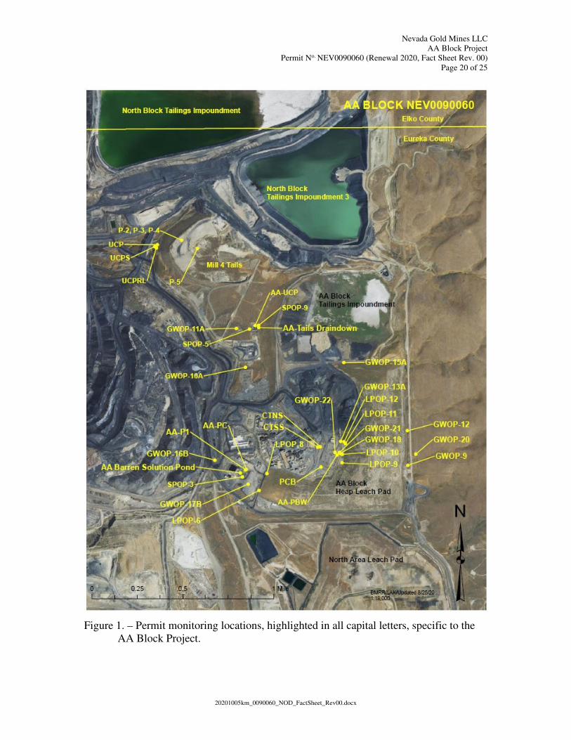
Figure 1 below provides a site map indicating all monitoring locations specific to
the AA Block Project. Monitoring location identifiers are presented in capital
letters. Specific process components are also identified. The North Block Tailings
Impoundment and Tailings Storage Facility 3 are monitored in WPCP
NEV0091029; North Area Leach Pad is monitored in WPCP NEV0087065 and are
included for relative location only.
Page 20
Nevada Gold Mines LLC
AA Block Project
Permit No. NEV0090060 (Renewal 2020, Fact Sheet Rev. 00)
Page 20 of 25
20201005km_0090060_NOD_FactSheet_Rev00.docx
Figure 1. – Permit monitoring locations, highlighted in all capital letters, specific to the
AA Block Project.
Page 21
Nevada Gold Mines LLC
AA Block Project
Permit No. NEV0090060 (Renewal 2020, Fact Sheet Rev. 00)
Page 21 of 25
20201005km_0090060_NOD_FactSheet_Rev00.docx
C. Receiving Water Characteristics
The Permittee’s mining and processing operations are located on the southwest
flank of the Tuscarora Mountains in north-central Nevada. The facilities lie in the
Little Boulder Basin, which is a topographic feature that contains the Brush, Rodeo,
and Bell Creek drainages. In the Goldstrike area, which includes the AA Block
Project, elevations range from about 5,100 feet to 5,926 feet AMSL. The terrain in
the vicinity of the Project is typical of the Basin and Range physiographic province,
and is dominated by north-trending fault-block mountain ranges that expose
sedimentary rocks.
Surface Hydrology
A detailed description of the regional surface hydrology can be found in the
Assessment of Area of Review for the AA Block. A detailed description of the
site-specific surface hydrology can also be found in referenced documents listed in
the WPCP application.
In general, surface runoff from the AA Block Project area flows west and southwest
via Brush and Rodeo creeks. The Rodeo Creek diversion, which diverts Rodeo
Creek around the Betze-Post Pit and associated facilities, flows northeasterly
through the Project before bending west and southwest through the North Block
Project (WPCP NEV0091029). The water quality of these creeks has been
established via Permit requirements. In general, Brush Creek background water
quality constituent concentrations meet Profile I reference values. Rodeo Creek
typically shows higher arsenic, iron, and manganese background concentrations.
Surface flow in these drainages infiltrates into the alluvium beneath and adjacent
to the creeks. The Division has not designated beneficial uses or established
numerical surface water quality standards for Brush Creek or Rodeo Creek.
Hydrogeology
Shallow alluvial deposits are found primarily adjacent to drainages within the
Project area. Subsurface drainage within these deposits generally appears to follow
the course of these drainages to Rodeo Creek or into the underlying or adjacent
Carlin Formation. The alluvial deposits generally consist of interbedded clay, silt,
sand, and gravel deposited by channel and overbank flows of the creek. The
permeability of the alluvium ranges from 1 x 10⁻⁴ cm/sec to 8 x 10⁻² cm/sec.
The Carlin Formation, which is found east and north of Rodeo Creek, underlies the
Little Boulder Basin regionally and extends under the AA Tails, Mill 4 TSF1, and
the AA Block HLF. This formation has a regional thickness of 600 feet and consists
of materials that generally exhibit low permeability. In the AA Block Project area,
the Carlin Formation permeability ranges from 5.2 x 10⁻⁶ cm/sec to 8.3 x 10⁻⁵
cm/sec. The variable nature of the formation results in lenses of more permeable
material along the bedding planes within the formation. Very little vertical flow
occurs and the Carlin Formation acts as an aquitard, producing locally confined
conditions within the underlying Vinini Formation. Most of the recharge of the
Carlin Formation is derived from direct infiltration of precipitation and snow melt
Page 22
Nevada Gold Mines LLC
AA Block Project
Permit No. NEV0090060 (Renewal 2020, Fact Sheet Rev. 00)
Page 22 of 25
20201005km_0090060_NOD_FactSheet_Rev00.docx
from the Tuscarora Mountains. This source of local recharge is directly responsible
for variations in groundwater quality in the Carlin Formation as opposed to
underlying metasediments.
The original groundwater gradient beneath this area was northeast to southwest,
with a pre-mining groundwater elevation of approximately 5,320 feet AMSL.
However, dewatering operations have reduced local groundwater elevations to
approximately 3,596 feet AMSL below mining operations and have resulted in a
localized zone of groundwater depression that is observed west-southwest of the
AA Block facilities. Continued dewatering activities in the Project area are
expected to maintain the water table at depth (approximately 2,500 to 3,500 feet
below ground surface) in the AA Block area.
GWOP-9, GWOP-12, and GWOP-20 are located on the eastern side of the property
upgradient of the AA HLP and are most representative of background groundwater
quality. Background water quality in the Carlin Formation is generally good,
meeting all Division Profile I reference values, with an occasional exceedance of
arsenic.
However, beginning in the fourth quarter of 2004, GWOP-12 has indicated
exceedances of chloride and TDS. In March 2015, following ongoing discussions
with the Division, the Permittee conducted an investigation of the area surrounding
GWOP-12 as well as developing historical concentration plots of the correlation
between chloride and magnesium. The historical plots identified that a strong
correlation exists between the chloride and magnesium trends over the span of the
entire dataset. The model output indicated an R2 value of 0.98.
Given the strong statistical correlation between chloride and magnesium and the
proximity of an upgradient stormwater feature to GWOP-12, the Permittee believes
that magnesium chloride used as a dust suppressant on nearby roads is the source
of elevated chloride and TDS in GWOP-12. Since no other constituents are present
in concentrations above background conditions at this location, as compared to
GWOP-9 and GWOP-20, the Permittee believes the well is still functioning
adequately to provide background groundwater data relevant to the AA HLP and
will continue to monitor this well quarterly. In late 2015, the Permittee modified
the stormwater diversion controls to divert stormwater away from this location.
Additionally, to eliminate the contaminant source, the Permittee switched from the
use of magnesium chloride to lignin sulfonate for dust suppression and, with the
construction of TSF3, the access road that parallels the GWOP-12 location is no
longer used as a main access road. Although sporadic, both the chloride and TDS
trends appear to be decreasing.
Well Locations in the Project Area
Numerous groundwater monitoring wells and piezometers exist within the Project
area. The locations of the wells within the AA Block area can be found in the
WPCP application. These wells are monitored, sampled, and results are submitted
as required by the Permit.
Page 23
Nevada Gold Mines LLC
AA Block Project
Permit No. NEV0090060 (Renewal 2020, Fact Sheet Rev. 00)
Page 23 of 25
20201005km_0090060_NOD_FactSheet_Rev00.docx
Well EW-14 provides potable water to the AA Block facilities.
D. Procedures for Public Comment
The Notice of the Division’s intent to issue a Permit authorizing the facility to
construct, operate and close, subject to the conditions within the Permit, is being
published on the Division website: https://ndep.nv.gov/posts/category/land. The
Notice is being mailed to interested persons on the Bureau of Mining Regulation
and Reclamation mailing list. Anyone wishing to comment on the proposed Permit
can do so in writing within a period of 30 days following the date the public notice
is posted to the Division website. The comment period can be extended at the
discretion of the Administrator. All written comments received during the
comment period will be retained and considered in the final determination.
A public hearing on the proposed determination can be requested by the applicant,
any affected State, any affected intrastate agency, or any interested agency, person
or group of persons. The request must be filed within the comment period and must
indicate the interest of the person filing the request and the reasons why a hearing
is warranted.
Any public hearing determined by the Administrator to be held must be conducted
in the geographical area of the proposed discharge or any other area the
Administrator determines to be appropriate. All public hearings must be conducted
in accordance with NAC 445A.403 through NAC 445A.406.
E. Proposed Determination
The Division has made the tentative determination to issue the renewed Permit.
E. Pathway to Final Closure and Permit Termination
See Section I of the Permit.
In accordance with NAC 445A.409 and 445A.446, for final closure and Permit
termination the Permittee must demonstrate to the Division that: 1) all sources at
the facility have been stabilized, removed, or mitigated; 2) any applicable
requirements in NAC 445A.429, 445A.430, and 445A.431 have been achieved; and
3) sufficient post-closure monitoring has occurred to verify the adequacy of these
actions to ensure the long-term protection of waters of the State, human health, and
wildlife under the physical, chemical, and climatic conditions reasonably expected
to occur at the site. If the facility includes a long-term trust and/or requires
perpetual treatment or maintenance, post-closure monitoring may never be reached
and the Division may not be able to terminate the Permit.
The pathway to final closure and Permit termination at this facility includes the
following specific actions:
• Submit a Tentative Plan for Permanent Closure (TPPC) for conversion of the
AA Barren Pond to an E-Cell;
• Complete approved permanent closure actions on the AA HLF and E-Cell, AA
TSF, and Mill4 TSF1;
Page 24
Nevada Gold Mines LLC
AA Block Project
Permit No. NEV0090060 (Renewal 2020, Fact Sheet Rev. 00)
Page 24 of 25
20201005km_0090060_NOD_FactSheet_Rev00.docx
• Submit a final closure report for the AA HLF and E-Cell, AA TSF, and Mill4
TSF1, ;
• Complete remedial activities at LPOP-10 and GWOP-22 locations in
accordance with the approved CAP;
• Monitor the facility through major storms and large winter/spring seasons to
verify that closed components and the fluid management system remain
functional with no potential for degradation of waters of the State;
• Discuss with the Division whether the facility is ready for final closure and
Permit termination. If so, submit for review and approval a request for final
closure and Permit termination including a demonstration of compliance with
all applicable closure requirements (e.g., NAC 445A.379, 445A.409,
445A.424, 445A.429, 445A.430, 445A.431, 445A.446, 445A.447).
The Division may require additional actions if warranted in accordance with site
conditions and applicable statutes, regulations, orders, and Permit conditions.
G. Rationale for Permit Requirements
Ongoing closure-related investigations and remediation activities continue and the
results of these investigations/remediation activities may induce changes to existing
component closure plans and WPCP rationale/requirements.
Seepage occurring at the AA Block HLF will continue to be actively pumped and
monitored. These activities will occur until it can be demonstrated that water
quality is stable, meets Profile I reference values and will not degrade waters of the
State.
With the expedited closure of the AA Tailings Facility, i.e., elimination of process
water from the tails surface, water quality monitored at GWOP-10A and GWOP-
15A is expected to improve; monitoring of the wells will continue until it can be
demonstrated that water quality is stable, meets Profile I reference values and will
not degrade waters of the State. Based on the results of this monitoring, additional
mitigation actions may be required.
The facility is located in an area where annual evaporation is greater than annual
precipitation. Therefore, it must operate under a standard of performance which
authorizes no discharge(s) except for those accumulations resulting from a storm
event beyond that required by design for containment.
The primary methods used for identification of escaping process solution will be
required routine monitoring of leak detection systems, as well as routine sampling
of downgradient monitoring wells. Specific monitoring requirements can be found
in Part I.D of the Permit.
Facilities will be monitored and operated in accordance with the Permit conditions
and the operating plans.
Page 25
Nevada Gold Mines LLC
AA Block Project
Permit No. NEV0090060 (Renewal 2020, Fact Sheet Rev. 00)
Page 25 of 25
20201005km_0090060_NOD_FactSheet_Rev00.docx
H. Federal Migratory Bird Treaty Act
Under the Federal Migratory Bird Treaty Act, 16 U.S. Code 701-718, it is unlawful
to kill migratory birds without license or permit, and no permits are issued to take
migratory birds using toxic ponds. The Federal list of migratory birds (50 Code of
Federal Regulations 10, 15 April 1985) includes nearly every bird species found in
the State of Nevada. The U.S. Fish and Wildlife Service is authorized to enforce
the prevention of migratory bird mortalities at ponds and tailings impoundments.
Compliance with State permits may not be adequate to ensure protection of
migratory birds for compliance with provisions of Federal statutes to protect
wildlife.
Open waters attract migratory waterfowl and other avian species. High mortality
rates of birds have resulted from contact with toxic ponds at operations utilizing
toxic substances. The Service is aware of two approaches that are available to
prevent migratory bird mortality: 1) physical isolation of toxic water bodies through
barriers (e.g., by covering with netting), and 2) chemical detoxification. These
approaches may be facilitated by minimizing the extent of the toxic water. Methods
which attempt to make uncovered ponds unattractive to wildlife are not always
effective. Contact the U.S. Fish and Wildlife Service at 1340 Financial Boulevard,
Suite 234, Reno, Nevada 89502-7147, (775) 861-6300, for additional information.
Prepared by: Karl W. McCrea
Date: 05 October 2020
Revision 00: Renewal; Permit effective date 28 October 2020.