127
Factor Graph Based Detection Schemes forMobile Terrestrial DVB Systems with Long
OFDM Blocks
Pello Ochandiano Campo
Supervisors:
Mikel Mendicute Errasti
and
Jon Altuna Iraola
MONDRAGON
UNIBERTSITATEA
A thesis submitted for the degree of
Doctor by Mondragon Unibertsitatea
Department of Electronics and Computer Science
Mondragon Goi Eskola Politeknikoa
Mondragon Unibertsitatea
April 2012


Zuontzat guztiontzat...
eta zuretzat bereziki.


Eskertza
Lau urteko ibilbidearen ondoren jende askoren laguntza eskertu behar dut, beraiei esker izan
ez balitz ez nintzateke hona iritsiko eta. Lantaldean eta elkarrekintzan nire burua aberastu
dut eta modu baten edo beste baten jende askok izan du zerikusirik lan honen emaitzan.
Nire esker ona erakutsi nahi diet bereziki:
• Nire tesi zuzendari Mikel Mendikute doktore jaunari lehenengo eta behin, beti hor
egon delako. Bere zuzendaritza lanak eta gomendioek egin dute posible ikerketa lan
hau. Eskerrak baita ere Jon Altuna doktore jaunari lan honen zuzendaritzan parte
hartu duelako.
• Eusko Jaurlaritzako Industria, Berrikuntza, Merkataritza eta Turismo sailari eta Fagor
Elektronikari IKERTU programako bekaren bidez emandako laguntzagatik.
• Mondragon Unibertsitateko Goi Eskola Politeknikoari bertan tesia egiteko aukera eman
izanagatik.
• Goteborg-eko (Suedia) Chalmers University-ko Communications Systems and Infor-
mation Theory sailari bertan zortzi hilabeteko estantzia egiteko aukera ematearren.
• Henk Wymeersch doktore jaunari Suedian egindako estantzian zehar nire ikerketa lana
zuzendu zuelako.
• Nire lankide izan diren Iker Sobrón eta Lorena Martínez-i. Hirurok batera elkarlanean
garatu dugu DVB-T2 simulatzailea eta horrekin batera ehundaka eztabaida izan ditugu
bidean aurkitzen joan garen arazo teknikoen inguruan.
• Departamentuan lankide izan ditudanei: Maitane Barrenetxea, Idoia Jimenez, Aritz,
Maite, Lorea, Iñaki... kafe orduak ere ikerketa lanaren parte direlako.
• Chalmers-en lankide izan nituenei: bereziki Alex Graell-i bere konpainiak Suediako
egun ilunak argitu zituelako. Nire esker ona baita ere Alex Alvaradori.
iii

Acknowledgments
It is four years since I began to work on this research work. After this long journey I would
like to express my gratitude to the people who have support me in many di�erent ways:
• First of all, my supervisor Dr. Mikel Mendikute for his unconditional help and support.
Without his guidance, I would not reach this point. I also want to thank Dr. Jon
Altuna for his advice.
• The Department of Industry and Innovation of the Basque Government and Fagor
Electrónica for the funding received through a IKERTU program grant.
• The High Polytechnical School of the University of Mondragon, for the chance to
develop the PhD.
• Communications Systems and Information Theory division of Chalmers University,
and specially to Dr. Henk Wymeersch for his help and support during my internship
in Sweden.
• To my current and past colleges Lorena Martínez and Iker Sobrón. We have jointly
developed the DVB-T2 simulator and we have had hundreds of technical discussions.
• To my PhD colleges who accompanied me along the last four years: Maitane Bar-
renetxea, Idoia Jimenez, Aritz, Maite, Lorea, Iñaki... co�ee breaks are fundamental
part of the research work.
• To the people I met in Chalmer University for their kindness and con�dence. Especially
to Alex Graell, for his joyful presence in Gothenburg, and to Alex Alvarado.
iv

Laburpena
Doktoretza tesi honek bigarren belaunaldiko telebista digitalaren eraginkortasuna aztertzen
du eskenatoki mugikorrean, eta faktoreen grafoetan oinarritzen den hartzaile iteratibo bat
proposatzen du denboran aldakorra den kanalak sortzen duen distortsioa leundu eta seinalea
errorerik gabe hartzea ahalbidetzen duena. Proposatutako detektorea BICM-OFDM ko-
munikazio eskema orokor baten gainean ebaluatu da lurreko broadcasting kanalaren bald-
intzak kontutan hartuz. Simulazio emaitzek algoritmo honen eraginkortasuna frogatzen dute
Doppler frekuentzia handietan. Ikerketa lanaren bigarren zatian, faktoreen grafoetan oinar-
ritutako detektorea eskema turbo zabalago baten baitan txertatu da LDPC dekodi�katzaile
batekin batera. Hartzaile diseinu honen abantaila nagusia da OFDM simbolo luzeetara
ondo egokitzen dela. Azkenik, proposatutako algoritmoa DVB-T2 katearen baitan inple-
mentatu da, bi hartzaile eskema proposatu direlarik seinaleak duen dibertsitate tenporal eta
frekuentziala probesteko, beti ere eraginkortasunaren, konplexutasunaren eta latentziaren
arteko konpromisoa mantenduz.
v

Resumen
Este trabajo de tesis analiza el rendimiento de la segunda generación de la televisión digital
terreste en escenarios móviles y propone un algoritmo iterativo basado en grafos de factores
para la detección de la señal y la reducción de la distorsión causada por la variación temporal
del canal, permitiendo así recibir la señal libre de errores. El detector basado en grafos de
factores propuesto es evaluado sobre un esquema de comunicaciones general BICM-OFDM
en condiciones de transmisión propios de canales de difusión terrestres. Los resultados de
simulación presentados muestran la e�ciencia del algoritmo de detección propuesto en pres-
encia de frecuencias Doppler muy altas. En una segunda parte del trabajo de investigación,
el detector propuesto es incorporado a un esquema turbo junto con un decodi�cador LDPC,
dando lugar a un receptor iterativo que presenta características especialmente apropiadas
para su implementación en sistemas OFDM con longitudes de símbolo elevadas. Por úl-
timo, se analiza la implementación del algoritmo propuesto sobre la cadena de recepción de
DVB-T2. Se presentan dos esquemas de recepción que explotan la diversidad temporal y
frecuencial presentes en la señal afectada por canales variantes en el tiempo, consiguiendo
un compromiso razonable entre rendimiento, complejidad y latencia.
vi
Abstract
This PhD dissertation analyzes the performance of second generation digital video broad-
casting (DVB) systems in mobile terrestrial environments and proposes an iterative detection
algorithm based on factor graphs (FG) to reduce the distortion caused by the time variation
of the channel, providing error-free communication in very severe mobile conditions. The
research work focuses on mobile scenarios where the intercarrier interference (ICI) is very
high: high vehicular speeds when long orthogonal frequency-division multiplexing (OFDM)
blocks are used.
As a starting point, we provide the theoretical background on the main topics behind the
transmission and reception of terrestrial digital television signals in mobile environments,
along with a general overview of the main signal processing techniques included in last
generation terrestrial DVB systems. The proposed FG-based detector design is then assessed
over a simpli�ed bit-interleaved coded modulation (BICM)-OFDM communication scheme
for a wide variety of mobile environments. Extensive simulation results show the e�ectiveness
of the proposed belief propagation (BP) algorithm over the channels of interest in this
research work. Moreover, assuming that low density parity-check (LDPC) codes are decoded
by means of FG-based algorithms, a high-order FG is de�ned in order to accomplish joint
signal detection and decoding into the same FG framework, o�ering a fully parallel structure
very suitable when long OFDM blocks are employed.
Finally, the proposed algorithms are analyzed over the physical layer of DVB-T2 speci�-
cation. Two reception schemes are proposed which exploit the frequency and time-diversity
inherent in time-varying channels with the aim of achieving a reasonable trade-o� among
performance, complexity and latency.
vii

Declaration of Originality
I hereby declare that the research recorded in this thesis and the thesis itself were devel-
oped entirely by myself at the Signal Theory and Communications Area, Department of
Electronics and Computer Science, at the University of Mondragon.
The software used to perform the simulations was developed entirely by myself, with the
following exceptions: the Matlab implementation of the basic transmission-reception chain
of the DVB-T2 simulator has been jointly developed by Lorena Martínez, Iker Sobrón and
myself. The implementation of the channel estimation algorithm employed in Chapter 5 has
been carried out by Lorena Martínez.
Pello Ochandiano Campo
Department of Electronics and Computer Science
Mondragon Goi Eskola Politeknikoa
Mondragon Unibertsitatea
April, 2012
viii

Contents
Acknowledgments . . . . . . . . . . . . . . . . . . . . . . . . . . . . . . . . . . . . iii
Abstract . . . . . . . . . . . . . . . . . . . . . . . . . . . . . . . . . . . . . . . . . v
Declaration of Originality . . . . . . . . . . . . . . . . . . . . . . . . . . . . . . . viii
Contents . . . . . . . . . . . . . . . . . . . . . . . . . . . . . . . . . . . . . . . . . ix
List of Figures . . . . . . . . . . . . . . . . . . . . . . . . . . . . . . . . . . . . . . xi
List of Tables . . . . . . . . . . . . . . . . . . . . . . . . . . . . . . . . . . . . . . xv
List of Symbols . . . . . . . . . . . . . . . . . . . . . . . . . . . . . . . . . . . . . xxi
1 Introducción 1
1.1 Motivación . . . . . . . . . . . . . . . . . . . . . . . . . . . . . . . . . . . . . 2
1.2 Objetivos . . . . . . . . . . . . . . . . . . . . . . . . . . . . . . . . . . . . . 3
1.3 Contribuciones de la Tesis . . . . . . . . . . . . . . . . . . . . . . . . . . . . 4
1.4 Estructura de la Tesis . . . . . . . . . . . . . . . . . . . . . . . . . . . . . . 4
2 Background and Related Work 6
2.1 Introduction . . . . . . . . . . . . . . . . . . . . . . . . . . . . . . . . . . . . 6
2.2 Fundamentals of the wireless channel . . . . . . . . . . . . . . . . . . . . . . 6
2.3 BICM-OFDM communication scheme . . . . . . . . . . . . . . . . . . . . . . 8
2.3.1 Bit-interleaved coded modulation . . . . . . . . . . . . . . . . . . . . 9
2.3.1.1 An information-theoretical view . . . . . . . . . . . . . . . . 10
2.3.2 Orthogonal frequency-division multiplexing . . . . . . . . . . . . . . . 12
2.3.2.1 Frequency-diversity through coding and interleaving . . . . 13
2.4 Low-density parity-check codes . . . . . . . . . . . . . . . . . . . . . . . . . 14
2.4.1 LDPC codes in DVB . . . . . . . . . . . . . . . . . . . . . . . . . . . 15
2.4.2 Decoding algorithms . . . . . . . . . . . . . . . . . . . . . . . . . . . 16
2.5 Time-varying fading channels . . . . . . . . . . . . . . . . . . . . . . . . . . 18
2.5.1 Performance degradation of OFDM systems due to Doppler spreading 20
2.5.1.1 Intercarrier interference . . . . . . . . . . . . . . . . . . . . 21
2.5.2 Exploiting time-domain diversity . . . . . . . . . . . . . . . . . . . . 24
ix

2.6 Terrestrial digital television . . . . . . . . . . . . . . . . . . . . . . . . . . . 25
2.6.1 DVB-T2 . . . . . . . . . . . . . . . . . . . . . . . . . . . . . . . . . . 26
2.6.2 Multipath channel models for terrestrial television . . . . . . . . . . . 28
2.7 The turbo principle in mobile communications . . . . . . . . . . . . . . . . . 29
2.7.1 BICM-ID . . . . . . . . . . . . . . . . . . . . . . . . . . . . . . . . . 30
2.8 Intercarrier interference cancellation schemes . . . . . . . . . . . . . . . . . . 31
2.9 Chapter Summary . . . . . . . . . . . . . . . . . . . . . . . . . . . . . . . . 33
3 Factor graph-based detection for channels a�ected by ICI 34
3.1 Introduction . . . . . . . . . . . . . . . . . . . . . . . . . . . . . . . . . . . . 34
3.2 Basic concepts . . . . . . . . . . . . . . . . . . . . . . . . . . . . . . . . . . . 35
3.2.1 Factor graphs and inference . . . . . . . . . . . . . . . . . . . . . . . 35
3.2.2 Building a factor graph . . . . . . . . . . . . . . . . . . . . . . . . . . 36
3.2.3 SP algorithm . . . . . . . . . . . . . . . . . . . . . . . . . . . . . . . 38
3.2.4 Messages and their representation . . . . . . . . . . . . . . . . . . . . 39
3.2.4.1 Message-scaling . . . . . . . . . . . . . . . . . . . . . . . . . 40
3.3 Loopy factor graphs . . . . . . . . . . . . . . . . . . . . . . . . . . . . . . . . 41
3.4 System description . . . . . . . . . . . . . . . . . . . . . . . . . . . . . . . . 42
3.5 Maximum a posteriori symbol detection based on factor graphs . . . . . . . 44
3.5.1 Optimal maximum a posteriori symbol detection . . . . . . . . . . . . 45
3.5.2 Forney approach . . . . . . . . . . . . . . . . . . . . . . . . . . . . . 46
3.5.2.1 Convergence analysis . . . . . . . . . . . . . . . . . . . . . . 47
3.5.2.2 Exploiting frequency-diversity . . . . . . . . . . . . . . . . . 48
3.5.2.3 BER and FER analysis . . . . . . . . . . . . . . . . . . . . 49
3.5.3 Ungerboeck approach . . . . . . . . . . . . . . . . . . . . . . . . . . . 51
3.5.4 Forney approach vs Ungerboeck approach . . . . . . . . . . . . . . . 52
3.5.4.1 Kullback-Leibler divergence analysis . . . . . . . . . . . . . 53
3.5.5 BP detection vs MAP detection with ICI cancellation . . . . . . . . . 56
3.6 Complexity analysis . . . . . . . . . . . . . . . . . . . . . . . . . . . . . . . . 58
3.7 Chapter Summary . . . . . . . . . . . . . . . . . . . . . . . . . . . . . . . . 58
4 Turbo approach for intercarrier interference cancellation 60
4.1 Introduction . . . . . . . . . . . . . . . . . . . . . . . . . . . . . . . . . . . . 60
4.2 System description . . . . . . . . . . . . . . . . . . . . . . . . . . . . . . . . 61
4.3 Pilot-assisted factor graph based detection . . . . . . . . . . . . . . . . . . . 64
4.4 Classical approach . . . . . . . . . . . . . . . . . . . . . . . . . . . . . . . . 65
4.4.1 EXIT chart analysis . . . . . . . . . . . . . . . . . . . . . . . . . . . 66
4.4.1.1 Numerical results . . . . . . . . . . . . . . . . . . . . . . . . 67
4.5 Graphical approach . . . . . . . . . . . . . . . . . . . . . . . . . . . . . . . . 69

4.6 Chapter Summary . . . . . . . . . . . . . . . . . . . . . . . . . . . . . . . . 73
5 Impact of BP-based ICI cancellation in mobile DVB-T2 74
5.1 Introduction . . . . . . . . . . . . . . . . . . . . . . . . . . . . . . . . . . . . 74
5.2 DVB-T2 to pave the way of DVB-NGH . . . . . . . . . . . . . . . . . . . . . 75
5.2.1 The bene�ts of employing long OFDM blocks in terrestrial broadcast-
ing systems . . . . . . . . . . . . . . . . . . . . . . . . . . . . . . . . 76
5.3 DVB-T2 performance in mobile scenarios . . . . . . . . . . . . . . . . . . . . 77
5.4 Belief propagation detection over DVB-T2 . . . . . . . . . . . . . . . . . . . 79
5.4.1 First proposed reception scheme (PS1) . . . . . . . . . . . . . . . . . 80
5.4.1.1 Performance with ideal CSI . . . . . . . . . . . . . . . . . . 80
5.4.1.2 Performance with channel estimation . . . . . . . . . . . . . 81
5.4.2 Second proposed reception scheme (PS2) . . . . . . . . . . . . . . . . 83
5.4.2.1 Performance with ideal CSI . . . . . . . . . . . . . . . . . . 84
5.4.2.2 Performance with channel estimation . . . . . . . . . . . . . 84
5.5 Chapter Summary . . . . . . . . . . . . . . . . . . . . . . . . . . . . . . . . 85
6 Conclusions and Further Research 87
6.1 Summary . . . . . . . . . . . . . . . . . . . . . . . . . . . . . . . . . . . . . 87
6.2 Thesis Contributions . . . . . . . . . . . . . . . . . . . . . . . . . . . . . . . 88
6.3 Suggestions for Further Research . . . . . . . . . . . . . . . . . . . . . . . . 89
A Publications 91
References 94

List of Figures
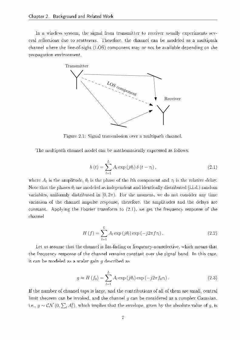
2.1 Signal transmission over a multipath channel. . . . . . . . . . . . . . . . . . 7
2.2 bit-interleaved coded modulation (BICM) transmitter. . . . . . . . . . . . . 9
2.3 BICM receiver with a turbo-like binary code. . . . . . . . . . . . . . . . . . . 9
2.4 Equivalent parallel channel model for BICM in the case of ideal interleaving. 10
2.5 Capacity of BICM over AWGN (a) and Rayleigh block fading (b) channels. . 12
2.6 Representation of �ve orthogonal subcarriers in orthogonal frequency-division
multiplexing (OFDM) transmission. . . . . . . . . . . . . . . . . . . . . . . . 13
2.7 Information outage probability for BICM over block Rayleigh fading channel
with 16quadrature-amplitude modulation (QAM) modulation. . . . . . . . . 14
2.8 Tanner graph for an example low density parity check (LDPC) code. Round
nodes represent variable nodes and square nodes represent check nodes. . . . 15
2.9 Message passing in the LDPC decoder. fj represents a variable node and cirepresents a check node. . . . . . . . . . . . . . . . . . . . . . . . . . . . . . 17
2.10 Clarke's model for time-varying Rayleigh fading channels. . . . . . . . . . . . 18
2.11 Representation of the time-varying frequency response of the channel H (a)
and the frequency response matrix H describing the ICI power distribution
(b). fd = 0.8 and TU6 channel has been considered. . . . . . . . . . . . . . . 23
2.12 The main three diagonals ofH for fd = 0.1 (a) and fd = 0.4 (b). The blue line
represents the main diagonal, and the red one and the green one represent the
�rst diagonal on the right side and the �rst diagonal on the left side, respectively. 23
2.13 Histogram of the LLRs a�ected by intercarrier interference (ICI). . . . . . . 24
2.14 DVB-T2 signal transmission over multipath channel pro�le with 100 Hz of
Doppler frequency. 16QAM and code rate (CR)= 2/3 is considered. . . . . . 25
2.15 Elementary transmission chain of DVB-T2. . . . . . . . . . . . . . . . . . . . 26
2.16 Available modes in DVB-T and DVB-T2. . . . . . . . . . . . . . . . . . . . . 27
xii

2.17 bit error rate (BER) performance of Digital Video Broadcasting-Terrestrial
(DVB-T) and DVB-T2 systems over additive white Gaussian noise (AWGN)
(a) and Rayleigh (b) channels. . . . . . . . . . . . . . . . . . . . . . . . . . . 28
2.18 Example of a turbo receiver. . . . . . . . . . . . . . . . . . . . . . . . . . . . 29
2.19 DVB.T2 performance with iterative demapping over the 6-tap typical urban
(TU6) channel. In the iterative case, 3 turbo iterations are considered and 20
LDPC iterations in each turbo iteration. In the non-iterative case, 50 LDPC
iterations are carried out. . . . . . . . . . . . . . . . . . . . . . . . . . . . . . 31
2.20 Summary of the main ICI suppressing schemes. . . . . . . . . . . . . . . . . 32
3.1 Simpli�ed discrete channel model, where neither OFDM modulation nor in-
terleaving has been considered for simplicity. . . . . . . . . . . . . . . . . . . 35
3.2 FG representing function f (s1, s2, s3, s4) = f1 (s1) f2 (s1, s2, s3) f3 (s3, s4). . . 37
3.3 The sum-product (SP) algorithm: message computation rule from function
node fk to variable node sm (a), and from variable node sn to function node
fl (b). . . . . . . . . . . . . . . . . . . . . . . . . . . . . . . . . . . . . . . . 38
3.4 Block diagram of the BICM-OFDM reception scheme including the belief
propagation (BP) detector. . . . . . . . . . . . . . . . . . . . . . . . . . . . . 43
3.5 Frequency-domain system input-output relation after CP removal. . . . . . . 43
3.6 Representation of part of the channel frequency response H for fd = 0.13 (a)
and fd = 0.4 (b). Higher power is represented by lighter color. TU6 channel
has been considered. . . . . . . . . . . . . . . . . . . . . . . . . . . . . . . . 44
3.7 The SP algorithm on a hidden-Markov model (HMM) with forward and back-
ward phases. . . . . . . . . . . . . . . . . . . . . . . . . . . . . . . . . . . . . 46
3.8 Factor Graph for the Forney approach-based maximum a posteriori (MAP)
symbol detection. . . . . . . . . . . . . . . . . . . . . . . . . . . . . . . . . . 47
3.9 Convergence analysis by means of BER performance vs number of iterations
for SP (a) and max-sum (MS) (b) algorithms at turbo cli� region. TU6
channel is assumed. . . . . . . . . . . . . . . . . . . . . . . . . . . . . . . . . 48
3.10 Percentages of suppressed ICI, non-suppressed ICI and residual ICI for di�er-
ent fd (a) and SNR vs fd at BER = 10−4 (b). MS algorithm is assumed. . . 49
3.11 BER vs SNR and FER vs SNR performance. . . . . . . . . . . . . . . . . . . 50
3.12 BER vs fd at SNR=7dB (a) and BER vs SNR for di�erent iterations when
MS algorithm is assumed (fd = 0.5) (b). . . . . . . . . . . . . . . . . . . . . 51
3.13 Factor Graph for the Ungerboeck approach-based MAP symbol detection. . . 53
3.14 Ungerboeck approach vs Forney approach for fd = 0.16 (a) fd = 0.4 (b). . . . 54
3.15 Kullback-Leibler divergence D (P ||Q), where P refers to the optimal FB al-
gorithm and Q represents the Forney approach BP algorithm and the Unger-
boeck approach BP algorithm in each case. . . . . . . . . . . . . . . . . . . . 55

3.16 SNR vs fd for the Forney approach BP detector, Ungerboeck approach BP
detector and optimal FB algorithm. . . . . . . . . . . . . . . . . . . . . . . . 55
3.17 Structure of the ICI suppressing soft demapper. . . . . . . . . . . . . . . . . 56
3.18 Stage 1 computes symbol estimates using a Viterbi-like algorithm. . . . . . . 57
3.19 MAP ICI canceler [Peng06] vs proposed BP detector for fd = 0.1 and 0.3. . . 57
4.1 Turbo receiver consisting of the concatenation of the detector and the decoder,
where the ICI channel works as a rate-1 inner code. . . . . . . . . . . . . . . 62
4.2 Block diagram of the BICM iterative receiver chain including the BP detector. 62
4.3 Example of a variable node processing a priori information of the correspond-
ing symbol. . . . . . . . . . . . . . . . . . . . . . . . . . . . . . . . . . . . . 63
4.4 Pilot processing in the factor graph. . . . . . . . . . . . . . . . . . . . . . . . 64
4.5 Example of a variable node processing a priori information of the correspond-
ing symbol in the classical turbo approach. . . . . . . . . . . . . . . . . . . . 66
4.6 Modeling a serial concatenated system with extrinsic information transfer
(EXIT) functions. . . . . . . . . . . . . . . . . . . . . . . . . . . . . . . . . . 67
4.7 Detector EXIT function for QPSK modulation (a) and detector and decoder
EXIT functions for 16QAM modulation with di�erent mapping schemes when
fd = 0.22 (b). TU6 channel has been considered in both cases. . . . . . . . . 68
4.8 EXIT chart (a) and BER vs LDPC iterations (b). QPSK modulation, TU6
channel, fd = 0.5 and SNR = 8 dB has been considered. . . . . . . . . . . . 69
4.9 High order FG performing joint data detection and decoding following the
graphical approach for turbo reeption. . . . . . . . . . . . . . . . . . . . . . 70
4.10 Performance comparison of non-turbo reception, classical turbo approach and
the graphical turbo approach for TU6 (a) and RA6 (b) channels. fd = 0.5
has been considered. . . . . . . . . . . . . . . . . . . . . . . . . . . . . . . . 70
4.11 BER vs SNR performance of the graphical approach for the �ve turbo iterations. 71
4.12 Graphical turbo approach performance for di�erent Doppler frequencies over
TU6 channel (a) and RA6 channel (b) when QPSK modulation is considered. 72
4.13 Graphical turbo approach performance for di�erent Doppler frequencies over
TU6 channel (a) and RA6 channel (b) when 16QAM modulation is considered. 72
5.1 Bitrate vs robustness trade-o�. . . . . . . . . . . . . . . . . . . . . . . . . . 75
5.2 Simpli�ed block diagram of the conventional DVB-T2 receiver (CONV). . . . 77
5.3 DVB-T2 performance versus di�erent number of FEC blocks in the TI-block
(time interleaving depth) at high SNR regime (SNR=30dB) for QPSK (a) and
16QAM (b). . . . . . . . . . . . . . . . . . . . . . . . . . . . . . . . . . . . . 79
5.4 Simpli�ed block diagram of the �rst proposed scheme (PS1). . . . . . . . . . 80

5.5 PS1 BER performance comparison for di�erent number of BP iterations, with
fd = 0.5 over TU6 channel, considering ideal and partial CSI. 10 FEC blocks
per TI-block are assumed (a). PS1 BER performance for di�erent number of
FEC blocks per TI-block, with fd = 0.5 over TU6 channel, considering 3 BP
iterations (b). . . . . . . . . . . . . . . . . . . . . . . . . . . . . . . . . . . . 81
5.6 PS1 BER performance comparison for di�erent numbers of BP iterations, with
fd = 0.5 over RA6 channel, considering ideal and partial CSI. 10 FEC blocks
per TI-block are assumed (a). PS1 BER performance for di�erent number of
FEC blocks per TI-block, with fd = 0.5 over RA6 channel, considering 3 BP
iterations (b). . . . . . . . . . . . . . . . . . . . . . . . . . . . . . . . . . . . 82
5.7 Simpli�ed block diagram of the second proposed scheme (PS2). . . . . . . . 83
5.8 PS2 BER performance for 3 BP iterations. fd = 0.5 over TU6 channel (a)
and RA6 channel (b). . . . . . . . . . . . . . . . . . . . . . . . . . . . . . . . 84

List of Tables
2.1 Serial concatenated systems with iterative detection/decoding. . . . . . . . . 30
3.1 Simulation parameters in Chapter 3. . . . . . . . . . . . . . . . . . . . . . . 45
3.2 Complexity analysis. . . . . . . . . . . . . . . . . . . . . . . . . . . . . . . . 58
5.1 Simulation parameters in Chapter 5. . . . . . . . . . . . . . . . . . . . . . . 78
xvi

Acronyms
BICM bit-interleaved coded modulation
CSI channel state information
AMI average mutual information
AWGN additive white Gaussian noise
CM coded modulation
eIRA extended irregular repeat-accumulate
BP belief propagation
CP cyclic pre�x
DFT discrete Fourier transform
DTV digital television
ASTC advanced television system committee
DTMB digital terrestrial multimedia broadcast
DVB Digital Video Broadcasting
DVB-T Digital Video Broadcasting-Terrestrial
DVB-NGH Digital Video Broadcasting-Next Generation Handheld
CR code rate
BER bit error rate
BCH Bose-Chaudhuri-Hocquegham
xvii

BICM-ID bit-interleaved coded modulation-iterative demapping
BILCM bit-interleaved LDPC coded modulation
BCJR Bahl Cocke Jelinek Raviv
CSI channel state information
BEM basic expansion model
EXIT extrinsic information transfer
BPSK binary phase-shift keying
LOS line-of-sight
LTE long term evolution
LLR log-likelihood ratio
FDM frequency-division multiplexing
ISI intersymbol interference
FER frame error rate
LDPC low density parity check
FEC forward error correction
ICI intercarrier interference
GI guard interval
IDFT inverse discrete Fourier transform
ISDB-T integrated services digital broadcasting-terrestrial
HDTV high de�nition television
GSM global system for mobile communication
FG factor graph
HMM hidden-Markov model
FFT fast Fourier transform
FB forward-backward

IFFT inverse fast Fourier transform
KL Kullback-Leibler
HD high de�nition
i.i.d. independent and identically distributed
OFDM orthogonal frequency-division multiplexing
MLC multilevel coding
ML maximum likelihood
MAP maximum a posteriori
QAM quadrature-amplitude modulation
RS Reed-Solomon
MP message-passing
MS max-sum
MP max-product
MSPCF max-sum plus-correction factor
PSK phase-shift keying
PDF probability density function
MPEG moving picture experts group
RQD rotated constellations and Q-delay
PAPR peak-to-average power ratio
QEF quasi error free
RA6 6-tap typical rural area
NLOS non line-of-sight
MMSE minimum mean-square error
MUI multiuser interference
PIC parallel interference cancellation

ML maximum likelihood
QPSK quadrature phase-shift keying
RSSD Reduced state sequence detection
MSEW maximum squared euclidian weight
SNR signal to noise ratio
SP sum-product
SISO soft-in/soft-out
SIC successive interference cancellation
SAGE generalized expectation maximization
SD sphere decoding
SER symbol error rate
SFN single frequency networks
TCM trellis coded modulation
TU6 6-tap typical urban
ZF zero-forcing
VA Viterbi algorithm

List of Symbols
∆f Subcarrier spacing
c Speed of light
CBICM Bit interleaved coded modulation capacity
CCM Coded modulation capacity
CR Code rate
dfree Minimum Hamming distance
E (s) Average energy per symbol
E (x) Expectation of x
f frequency
Fc Carrier frequency
fc 3-dB-cuto� frequency
Fd Absolute Doppler frequency
fd Normalized Doppler frequency
G Hermitian matrix
Γ Constellation size
H Frequency-domain channel matrix
h Channel impulse response
H Time-varying frequency response of the channel
xxi

H Time-domain channel matrix
Hc Parity-check matrix
Kc Number of message bits in the codeword
L Number of taps or paths of a multipath channel
M Number of bits per symbol
Mc Number of parity bits in the codeword
N OFDM symbol length
N0 Noise power spectral density
Nc Codeword length
P0 Outage probability
P (a) Probability of event a
r Time-domain received signal column vector
R Coded modulation rate
s Frequency-domain transmitted signal column vector
s Hard estimate of symbol s
σ2n Variance of noise per real component
s Soft estimate of symbol s
SX Power spectral density
τ Tap delay
TC Coherence time of the channel
TIL Interleaver time span
Ts Sampling rate
Tu Length of the OFDM block
wc uniform column weight
wr uniform row weight

x Time-domain transmitted signal column vector
y Frequency-domain received signal column vector
z Time-domain additive white Gaussian noise column vector
zf Frequency-domain additive white Gaussian noise column vector

Capítulo 1
Introducción
La incorporación de la tecnología digital al mundo de la televisión supuso la apertura de
un horizonte plagado de oportunidades relacionadas con el tratamiento digital de la señal.
No obstante, más allá de lo estrictamente técnico, la televisión digital sentó las bases para
revolucionar el concepto de televisión. Nuevas características como el pago por visión, la
interactividad con el espectador, la integración de los aparatos audiovisuales domésticos,
etc. son los cimientos de este nuevo concepto. En este contexto, Digital Video Broadcasting
(DVB) se ha convertido en referencia mundial como consorcio encargado de crear y proponer
los procedimientos de estandarización para la televisión digital. Los estándares de mayor
repercusión comercial en la última década han sido DVB-C (televisión digital por cable, 1994)
[ETSI94], DVB-S (televisión digital por satélite, 1995) [ETSI95], DVB-T (televisión digital
terrestre, 1997) [ETSI97] y DVB-H (televisión digital terrestre para recepción en dispositivos
móviles, 2004) [ETSI04]. Los estándares propuestos por DVB han sido adoptados en gran
parte del mundo. No obstante, EEUU, China, Corea y Japón han desarrollado sus propias
especi�caciones.
Desde la de�nición de esta primera generación de la televisión digital, la electrónica
ha experimentado un avance sustancial en cuanto a técnicas de procesamiento de señal se
re�ere. Una década después se conocen nuevas técnicas de modulación y protección contra
errores que mejoran notablemente la capacidad y la robustez de la señal. Conjuntamente, los
últimos años han sido testigos de la emersión de demandas comerciales como el video bajo
demanda o la televisión de alta de�nición (HDTV), los cuales requieren de mayor e�ciencia
espectral. Todo ello ha dado lugar a la de�nición de la segunda generación de estándares
para la televisión digital. DVB-T2 [ETSI09] fue lanzada al mercado en 2009 incluyendo las
técnicas de codi�cación de canal más potentes, los códigos low density parity-check (LDPC),
y etapas de procesamiento de señal opcionales como la rotación de constelaciones, o la
codi�cación espacio-frecuencial. Estos avances han permitido acercarse considerablemente
al límite teórico de capacidad de Shannon.
En general, la variedad de escenarios de difusión puede ser muy diversa, más aún si se
añade como variable la movilidad del receptor, la cual es un requisito fundamental en los
receptores modernos. La cada vez mayor demanda y oferta de información en el mercado
1
Capítulo 1. Introducción
de las telecomunicaciones, incluida la televisión, y la tendencia a acceder a la información
en cualquier momento y/o lugar, genera una continua necesidad de evolución hacia sistemas
móviles que soporten mayores tasas de información con la misma o mayor robustez en su re-
cepción. En el Plan Técnico Nacional Español de la televisión digital terrestre (RD 944/2005)
ya se hablaba de la televisión en movilidad a través de DVB-H. No obstante, en el estado
español, estas emisiones nunca llegaron más allá de algunos proyectos piloto aislados. Otros
países con emisiones estables las abandonaron a lo largo de 2011. La causa del fracaso quizás
haya que buscarla en la parte comercial: demasiadas incógnitas para un modelo de negocio
que fue sustituido por el streaming a través de las redes 3G.
Con la introducción de la segunda familia de especi�caciones de televisión digital, la re-
cepción móvil vuelve a ser uno de los temas principales de estudio. De hecho, la movilidad
fue uno de los requisitos comerciales para el diseño de DVB-T2, y actualmente nos encon-
tramos inmersos en el proceso de de�nición de la segunda generación de televisión digital
terrestre para dispositivos móviles (DVB-NGH), cuyo diseño se está basando en el primero.
1.1 Motivación
Hoy en día convivimos con múltiples sistemas de comunicaciones inalámbricas tales como
redes de telefonía móvil, redes de área local WLAN (Wireless Local Area Network), redes de
área metropolitana (Wireless Metropolitan Area Network) o redes de difusión de señales de
radio y televisión. Este gran mercado se renueva constantemente con nuevos estándares que
optimizan el uso del limitado espectro electromagnético basándose en el procesado digital de
la señal. En este sentido, las redes de frecuencia única (SFN) juegan un papel fundamental.
Por otra parte, el estándar DVB-T2 introduce la posibilidad de transmitir múltiples
�ujos de entrada (PLP) ajustando los parámetros de transmisión a cada servicio especí�co.
Ahondando en este sentido, la aparición reciente del per�l Lite de la norma DVB-T2 puede
suponer un cambio cualitativo en el panorama de la televisión en movilidad, especialmente
para aquellos países que ya hayan adoptado el estándar DVB-T2. Se abre la posibilidad
de transmitir señales DVB-T2-Lite a través de un mismo canal de radiofrecuencia (RF) por
donde se emite contenido en DVB-T2. Se hace uso así de diferentes niveles de robustez para
cada tipo de señal, siendo la bondad del sistema que ambas tramas se pueden transmitir
al mismo tiempo por el mismo canal de RF. A modo de ejemplo, se podría realizar el
lanzamiento de un nuevo múltiplex DVB-T2 con servicios de calidad de imagen estándar
(SDTV) o alta de�nición (HDTV) que incorporara un PLP especí�co DVB-T2 Lite para
recepción en movilidad, renunciando a parte del ancho de banda en detrimento de un PLP
más robusto. Por lo tanto, no sería necesario invertir en el despliegue de una nueva red
especí�ca para dispositivos móviles.
Tanto para extender la cobertura en redes SFN, contribuyendo así a la optimización de las
2

Capítulo 1. Introducción
infraestructuras, como para aumentar la tasa efectiva de transmisión sin perder robustez, se
está imponiendo la utilización de longitudes elevadas de bloque orthogonal frequency-division
multiplexing (OFDM) (hasta 32K portadoras). No obstante, el uso de longitudes largas de
bloque OFDM presenta dos desafíos desde el punto de vista técnico: por una parte, la dis-
torsión que introduce la variación del canal puede resultar devastadora, ya que depende de
la separación entre portadoras en frecuencia. Por lo tanto, se requiere de técnicas de proce-
samiento de señal avanzadas que reduzcan el nocivo efecto de la interferencia interportadora
(ICI). Por otra parte, aumenta la complejidad de la implementación de los algoritmos en
hardware, lo que conlleva un potencial aumento de la latencia y el coste en los receptores de
televisión. En este sentido, desde el punto de vista de la implementación práctica, resulta
vital disenar algoritmos de baja complejidad que permitan el procesamiento de la señal a
alta velocidad.
1.2 Objetivos
Teniendo en cuenta lo expuesto anteriormente, los objetivos principales de esta tesis son los
siguientes:
• Análisis del estándar DVB-T2, como referencia fundamental de la segunda generación
de la televisión digital terrestre, en escenarios de movilidad.
• Diseño de un algoritmo de detección que permita la comunicación libre de errores
considerando una longitud de bloque OFDM elevada (e.g., 32K) y que el receptor se
mueve a alta velocidad, respetando las citadas restricciones de complejidad y latencia.
Para la consecución de estos objetivos se han abordado los siguientes objetivos parciales:
• De�nición de los modelos y condiciones de propagación de la señal de televisión digital
terrestre en movilidad.
• Evaluación de técnicas de detección de señal diseñadas especí�camente para canales
variantes en el tiempo que puedan ajustarse a los requisitos de diseño de estándares
de televisión digital de última generación.
• Búsqueda de alternativas de algoritmos iterativos de detección en combinación con los
códigos LDPC, restringiendo la complejidad del diseño de cara a su implementación
en hardware.
3

Capítulo 1. Introducción
1.3 Contribuciones de la Tesis
A continuación se listan las principales contribuciones de esta tesis doctoral:
• Análisis del rendimiento de la cadena física de DVB-T2 sobre modelos de canal pro-
pios de condiciones de radiodifusión terrestre. Se ha analizado la detección iterativa
propuesta en [DVB09]. Este trabajo ha sido publicado en [Mendicute10].
• Estudio de las técnicas de detección de señal y supresión de interferencia interportadora
adecuadas para su implementación en la cadena de recepción de DVB-T2. Concreta-
mente, se ha analizado el rendimiento del detector propuesto en [Peng06] para una
longitud de bloque OFDM de 128 subportadoras. Este trabajo ha sido publicado en
[Ochandiano10].
• Diseño de un novedoso algoritmo iterativo basado en grafos de factores para la de-
tección de la señal de televisión digital terrestre en receptores móviles. El detector
ha sido evaluado sobre un esquema bit-interleaved coded modulation (BICM)-OFDM.
Este trabajo ha sido publicado en [Ochandiano11b, Ochandiano11a].
• Se han analizado dos técnicas para la detección maximum a posteriori (MAP) en el
grafo de factores, comprobando que la propuesta en esta tesis obtiene mejores resul-
tados de rendimiento que la alternativa propuesta en [Haselmayr11]. Además, se ha
analizado el comportamiento del detector como parte de un esquema turbo junto con el
decodi�cador de LDPC. El receptor ha sido evaluado sobre un esquema BICM-OFDM.
Este trabajo ha sido propuesto para su publicación en [Ochandiano12b]. Actualmente
se encuentra en revisión.
• Implementación del receptor propuesto sobre la cadena de recepción de DVB-T2.
Análisis del rendimiento del detector junto con el entrelazador de tiempo incluido
en la especi�cación DVB-T2. Este trabajo ha sido propuesto para su publicación en
[Ochandiano12a]. Actualmente se encuentra en revisión.
1.4 Estructura de la Tesis
La memoria de la tesis está estructurada en seis capítulos. Este primer capítulo introduce al
lector en la temática de la tesis y presenta la motivación de la misma junto a los objetivos
más destacados. También se presentan las contribuciones más notables, señalándose las
publicaciones a los que han dado lugar.
El segundo capítulo recoge los fundamentos cientí�cos sobre los que se desarrolla el tra-
bajo de investigación. En primera instancia se introduce el canal inhalámbrico variante en el
4

Capítulo 1. Introducción
tiempo y los efectos de dicho canal tanto en el dominio temporal como en el frecuencial. A
continuación se describe el sistema de comunicaciones en el que se basa la nueva generación
de televisión digital, BICM-OFDM, y los códigos LDPC, responsables en gran parte del
incremento de capacidad en DVB-T2. Acto seguido se analiza el efecto de la variación del
canal sobre una señal OFDM y se describe la ICI como fuente de diversidad frecuencial. En
la segunda parte, se introducen las principales características de la capa física de DVB-T2,
se analiza el principio de funcionamiento del esquena turbo, y se hace un repaso bibliográ�co
de las técnicas de cancelación de ICI más relevantes propuestas en los últimos años.
En el tercer capítulo se presenta la contribución central de la tesis: el diseño del detector
basado en grafos de factores para receptores de elevada movilidad. En la primera parte
se exponen los fundamentos de los algoritmos iterativos basados en grafos de factores y
la problemática que esconde la presencia de bucles en dichos grafos. En la segunda parte
se describe la detección MAP de la señal afectada por ICI en base al algoritmo suma-
producto (SP) ejecutado sobre un grafo de factores. Para ello, se analizan dos modelos
conocidos actualmente para la ejecución de la detección MAP así como su efecto sobre el
rendimiento del detector: Ungerboeck y Forney. Se demuestra que la detección MAP en
base al modelo de Forney supera en rendimiento al modelo de Ungerboeck en las condiciones
de canal que interesan en este trabajo de investigación. Además, se realiza un análisis
comparativo del rendimiento del algoritmo y un potencial candidato propuesto anteriormente
en la bibliografía. Por último, se aborda la cuestión de la complejidad.
El cuarto capítulo se centra en el análisis del rendimiento del algoritmo propuesto como
parte integrante de un esquema turbo de nivel superior en el que se intercambia información
soft entre el detector y el decodi�cador LDPC. Se toman en cuenta dos procedimientos para
la ejecución del esquema turbo: el clásico, según el cual se intercambia información soft entre
dos procesadores independientes; y el grá�co, que comprende la visión de un único grafo en
el que se intercambian mensajes entre nodos. Se analiza el comportamiento del primero a
través de la curva de transferencia de información extrínseca (EXIT) y se muestran resultados
comparativos de rendimiento.
El quinto capítulo analiza el detector propuesto sobre la capa física de DVB-T2. Para ello
se proponen dos esquemas de recepción combinando el empleo del entrelazador de tiempo y
el esquema turbo introducido en el capítulo cuarto. Se considera tanto el conocimiento ideal
del canal como no ideal, analizando así el efecto del error de estimación sobre el detector. Se
muestran resultados de rendimiento para modelos de canal típicos de radiodifusión terrestre.
Por último, el sexto capítulo resume el trabajo realizado y las principales conclusiones
obtenidas, así como las líneas futuras que el autor plantea como posible extensión del trabajo
presentado en esta tesis.
5

Chapter 2
Background and Related Work
2.1 Introduction
Commercial requirements based on the demand of higher data rates, greater spectral e�-
ciencies and improved data integrity have triggered the speci�cation of recent broadband
high-speed communications standards. This is the case of IEEE's 802.16 family, long term
evolution (LTE) project, or the recently standardized Digital Video Broadcasting (DVB)
speci�cations. Mobility support is one of the key features of these new technologies, dealing
with the challenge of enabling mobile broadband services at high vehicular speeds. Either the
second generation DVB standards, with both terrestrial and handheld versions, or the IEEE
802.16m are good examples of the mobility requirements of new wireless communication
standards.
As a starting point, this chapter o�ers the theoretical background on the main topics
behind the transmission and reception of terrestrial digital television signals in mobile envi-
ronments. First of all, the fundamentals of wireless communication channels are reviewed,
along with their e�ects on the performance of received signals. On the other hand, a general
overview of the main signal processing techniques included in last generation terrestrial DVB
systems is drawn, giving a brief look at the diversity sources available in such communication
scenarios.
In the second part, we review the 'turbo principle', which is a basic mechanism in the
development of factor graph (FG)-based algorithms, and discuss the most remarkable ICI
suppressing techniques proposed in the recent literature, paying special attention to those
ones suitable for being implemented in terrestrial DVB systems.
2.2 Fundamentals of the wireless channel
The channel model plays a key role in communication systems design. A common approach
is to de�ne a statistical model based on a large set of measurements, in a way that the perfor-
mance can be assessed by simulation, averaging over a large amount of channel realizations.
6
Chapter 2. Background and Related Work
In a wireless system, the signal from transmitter to receiver usually experiments sev-
eral re�ections due to scatterers. Therefore, the channel can be modeled as a multipath
channel where the line-of-sight (LOS) component may or not be available depending on the
propagation environment.
LOS component
Transmitter
Receiver
Figure 2.1: Signal transmission over a multipath channel.
The multipath channel model can be mathematically expressed as follows:
h (t) =L∑
l=1
Al exp (jθl) δ (t− τl) , (2.1)
where Al is the amplitude, θl is the phase of the lth component and τl is the relative delay.
Note that the phases θl are modeled as independent and identically distributed (i.i.d.) random
variables, uniformly distributed in [0, 2π). For the moment, we do not consider any time
variation of the channel impulse response, therefore, the amplitudes and the delays are
constant. Applying the Fourier transform to (2.1), we get the frequency response of the
channel
H (f) =L∑
l=1
Al exp (jθl) exp (−j2πfτl) . (2.2)
Let us assume that the channel is �at-fading or frequency-nonselective, which means that
the frequency response of the channel remains constant over the signal band. In this case,
it can be modeled as a scalar gain g described as
g ≈ H (f0) =L∑
l=1
Al exp (jθl) exp (−j2πf0τl) . (2.3)
If the number of channel taps is large, and the contributions of all of them are small, central
limit theorem can be invoked, and the channel g can be considered as a complex Gaussian,
i.e., g ∼ CN (0,∑
lA2l ), which implies that the envelope, given by the absolute value of g, is
7

Chapter 2. Background and Related Work
a Rayleigh random variable. Moreover, in wireless communication channels, it is very com-
mon to have a LOS component which corresponds to the smallest delay and is signi�cantly
stronger than the other taps. In this case, the sum of the components apart from the LOS
path, grest, can be modeled as zero mean Gaussian, so that the channel gain is
g = A1 exp (j (θ1 − 2πf1τ1)) + grest. (2.4)
The envelope |g|, is a Rician random process and the channel is termed as Rician fading:
g ∼ CN(A1 exp (j (θ1 − 2πf1τ1)) ,
L∑
l=2
A2l
)(2.5)
Now, let assume that the transmitted signal has a bandwidth larger than the channel
coherence bandwidth, so that the channel is considered frequency-selective. Considering the
transmitted signal has bandwidth BW , we must modify the mathematical channel model in
(2.1) in a way that 1/BW -spaced taps are considered:
h (t) =∞∑
i=1
αiδ
(t− i
BW
), (2.6)
where each of the αi taps is obtained by means of summing a large number of unresolvable
taps as
αi ≈∑
k:τk≈ iBW
Ak exp jθk. (2.7)
The αi taps are independent, zero mean Gaussian random variables, and as a consequence,
the amplitudes |αi| are independent Rayleigh random variables. Note that, in the case of
LOS presence, the direct path is modeled as Rician rather than Rayleigh.
2.3 BICM-OFDM communication scheme
The BICM-OFDM communication scheme has been adopted by most of the last-generation
communication standards due to its simplicity, �exibility and performance in wireless envi-
ronments. This is the case of IEEE's 802.16 family [IEEE05, IEEE06], the LTE project, or
the recently standardized second generation DVB speci�cations [ETSI05, ETSI09]. In this
section, BICM-OFDM scheme is analyzed with the aim of o�ering a general overview of the
key features which make this communication scheme so robust in wireless channels.
8

Chapter 2. Background and Related Work
2.3.1 Bit-interleaved coded modulation
Massey proposed in 1974 [Massey74] to jointly design coding and modulation, thus founding
the �eld of coded modulation. The goal was to e�ciently combine high-order modulation
(high data rates) with strong channel coding schemes for high reliability. Two years later,
Ungerboeck presented trellis coded modulation (TCM) [Ungerboeck76] and Imai proposed
multilevel coding (MLC) [Imai77] as powerful coded modulation schemes. In contrast to
traditional approaches which tried to optimize the Hamming distance measure, in both TCM
and MLC schemes, the design strategy was to improve the Euclidean distance. Afterwards,
in 1992, BICM was introduced by Zehavi [Zehavi92], which consists of nothing but a serial
concatenation of a code, a bit-wise interleaver and a mapper. Caire, Taricco and Biglieri
[Caire98] proved that it is possible to achieve very close to capacity performance with BICM
when Gray mapping is used.
The information bits are encoded by a single encoder and interleaved by a random in-
terleaver∏. The coded and interleaved sequence c is partitioned in Ns subsequences cn of
length M , where
cn = (cn,1, ..., cn,m, ..., cn,M) . (2.8)
The bits cn are mapped at time index n to a symbol sn chosen from the 2M -ary signal
constellation χ according to the binary labeling map µ : {0, 1}M → χ.
EncoderMapping∏
Demuxui sn
cn,m
χ, µ
Figure 2.2: BICM transmitter.
Demodulator∏−1
cn,m
LD(cn,m)
From the channel Iterativedecoder
Figure 2.3: BICM receiver with a turbo-like binary code.
The optimum BICM receiver is the joint maximum likelihood (ML) decoder. However,
the complexity of a joint ML demapper and decoder is not manageable. Therefore, demap-
ping and decoding tasks are separated (Fig. 2.3) and the MAP soft demapping is performed
which uses the received value yn of the transmitted symbol sn to obtain estimates about the
corresponding bits cn,m. The log-likelihood ratio (LLR) for the bit estimate cn,m is described
as follows,
9
Chapter 2. Background and Related Work
LD (cn,m) = log
∑∀cn:cn,m=0 exp Λ (cn)
∑∀cn:cn,m=1 exp [Λ (cn)]
, (2.9)
with the metric
Λ (cn) = logP (yn|sn) +M∑
m=1
logP (cn,m) , (2.10)
where p (y|s) is the channel transition probability. Considering no a priori information and
omitting the terms that are independent of the sequence cn, we can rewrite the LLR for the
bit estimate cn,m as
LD (cn,m) = log
∑∀cn:cn,m=0 P (yn|sn)
∏Mj=1 P (cn,j)
∑∀cn:cn,m=1 P (yn|sn)
∏Mj=1 P (cn,j)
. (2.11)
Commonly, an equivalent channel model is de�ned for the BICM communication scheme
with ideal interleaving. It consists of a set ofM parallel independent and memoryless binary
input channels connected to the encoder output through a random switch, which models
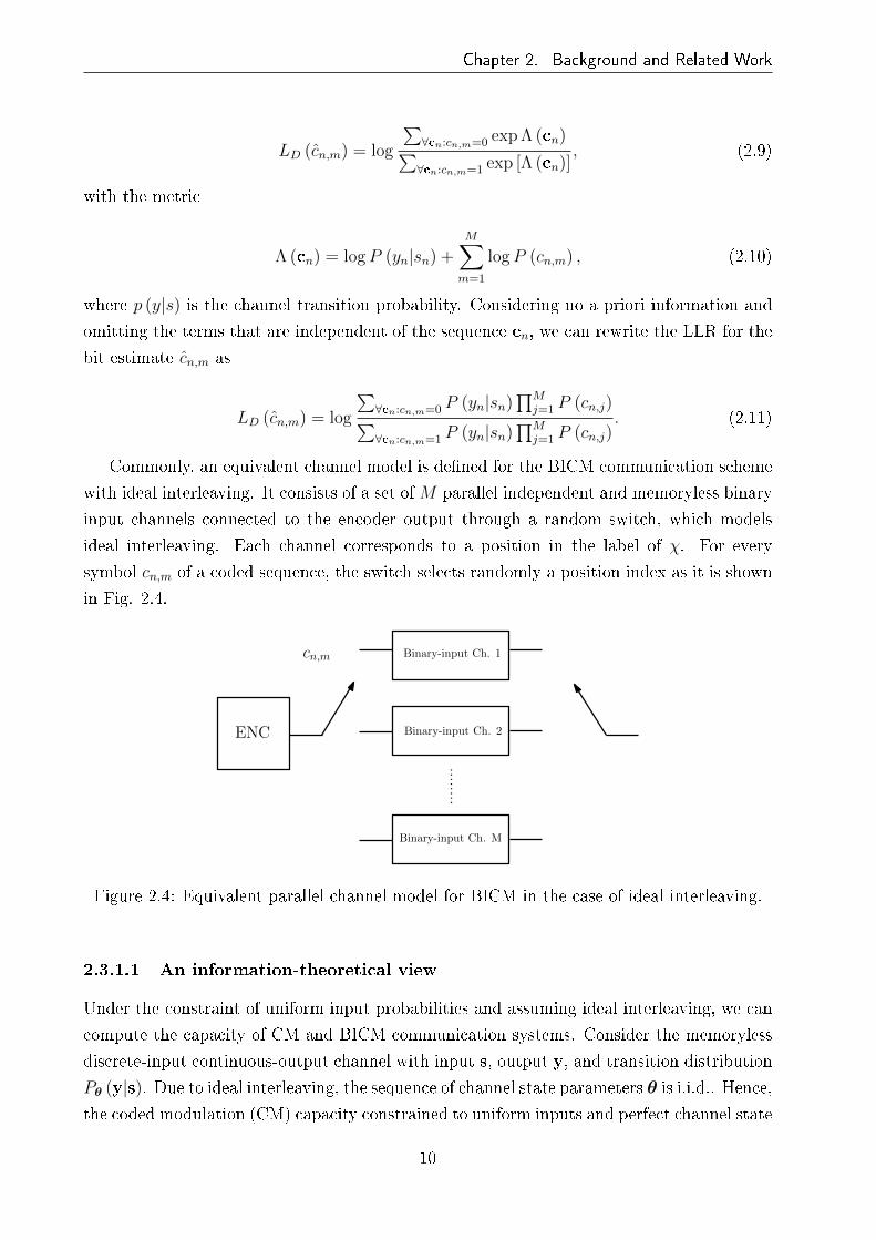
ideal interleaving. Each channel corresponds to a position in the label of χ. For every
symbol cn,m of a coded sequence, the switch selects randomly a position index as it is shown
in Fig. 2.4.
ENC
Binary-input Ch. 1
Binary-input Ch. 2
Binary-input Ch. M
cn,m
Figure 2.4: Equivalent parallel channel model for BICM in the case of ideal interleaving.
2.3.1.1 An information-theoretical view
Under the constraint of uniform input probabilities and assuming ideal interleaving, we can
compute the capacity of CM and BICM communication systems. Consider the memoryless
discrete-input continuous-output channel with input s, output y, and transition distribution
Pθ (y|s). Due to ideal interleaving, the sequence of channel state parameters θ is i.i.d.. Hence,
the coded modulation (CM) capacity constrained to uniform inputs and perfect channel state
10

Chapter 2. Background and Related Work
information (CSI) is given by the conditional average mutual information (AMI) [Caire98]
CCM = I (s;y|θ) = M − Es,y,θ
[log2
∑υ∈χ Pθ (y|υ)
Pθ (y|υ)
], (2.12)
where capacity is expressed in information bits per complex dimensions (bit/dim). It is
stated that CM communication system can achieve spectral e�ciencies R ≤ CCM .
In order to compute the capacity achievable by BICM, we are going to take into account
the parallel channel model described in Fig. 2.4. Let b denote a binary input, y the vector
channel output, and S the random variable whose output determines the switch position
(which we consider i.i.d., uniformly distributed and known to the receiver). Assuming perfect
CSI and uniform inputs, and since there areM parallel independent channels, the conditional
mutual information of b and y given S can be expressed as [Caire98]
CBICM = M · I(b;y|θ, S
)= M −
M∑
i=1
Eb,y,θ
[log2
∑υ∈χ Pθ (y|υ)∑υ∈χi
bPθ (y|υ)
], (2.13)
where it is shown that the capacity of the BICM channel is the average over the equivalent
channels of the bit positions. Expectations in (2.12) and (2.13) cannot be calculated in
closed form. Thus, numerical integration based on Monte Carlo method is used and the next
inequality can be proven:
CBICM ≤ CCM . (2.14)
BICM capacity strongly depends on the applied mapping. Fig. 2.5 depicts the capacity
of a standard BICM receiver using di�erent mappings over AWGN channel. As it is shown,
when Gray mapping is used, since the bit positions in the symbol labels are independent,
BICM capacity is closed to CM's capacity. However, a signi�cant loss is obtained for map-
pings di�erent from Gray as it is shown in Fig. 2.5. Capacity curves are also depicted for a
Rayleigh fading channel with coherent detection and it is shown that the sub-optimality of
BICM with respect to CM is maintained.
However, it is widely accepted that the analysis based on the cuto� rate R0 is more
sensible for comparing channels for which a �nite-complexity coding scheme is required.
The cuto� rate speci�es the highest information rate beyond which sequential decoding
becomes impractical. Again in [Caire98], simulation results based on cuto� rate are shown
over AWGN and Rayleigh channels, where it is concluded that, for a given complexity, BICM
outperforms CM over Rayleigh fading channel, especially for high rates. As a consequence, if
the channel obeys a Rician fading channel model and �uctuates in time between the extremes
of Rayleigh and AWGN (as is the case for mobile radio), the BICM scheme is more robust
than CM.
11

Chapter 2. Background and Related Work
−20 −10 0 10 20 30 400
0.5
1
1.5
2
2.5
3
3.5
4
SNR (dB)
Cap
acity
(bi
ts/c
hann
el u
se)
CM capacity of16QAM in AWGN channel
BICM capacity of 16QAM inAWGN channel. Graymapping
BICM capacity of 16QAMin AWGN channel. SP mapping
−30 −20 −10 0 10 20 30 40 500
0.5
1
1.5
2
2.5
3
3.5
4
SNR (dB)
Cap
acity
(bi
ts/c
hann
el u
se)
Ergodic BICMCapacity of 16QAM inRayleigh fading. Graymapping
Ergodic CM Capacity of16QAM in Rayleigh fadingchannel
Ergodic BICMCapacity of 16QAM inRayleigh fading. Graymapping
(a) (b)
Figure 2.5: Capacity of BICM over AWGN (a) and Rayleigh block fading (b) channels.
On the other hand, it is easy to realize intuitively which are the bene�ts of using coding
and interleaving. Since multipath fading channels vary across frequency, when a wide enough
bandwidth is employed, there can be good channel realizations as well as bad fades. Usually,
the former are more likely than the latter. Therefore, employing error correction coding
over a large enough frequency span prevents from a dramatical performance loss due to the
small fraction of symbols that experiment bad fades. Since typical codes are optimized to
correct random errors, the bit interleaver scrambles the errors along the entire codeword,
thus improving the system performance.
2.3.2 Orthogonal frequency-division multiplexing
OFDM is a frequency-division multiplexing (FDM) scheme used as a digital multi-carrier
modulation method. A large number of closely-spaced orthogonal subcarriers are used to
carry data (see Fig, 2.6), which are divided into several parallel data streams or channels, one
for each subcarrier. Each subcarrier is modulated with a conventional modulation scheme
(such as QAM) at a low symbol rate, maintaining total data rates similar to conventional
single-carrier modulation schemes in the same bandwidth.
The primary advantage of OFDM over single-carrier schemes is its ability to cope with
severe channel conditions (i.e., narrowband interference and frequency-selective fading due to
multipath) without complex equalization �lters. Channel equalization is simpli�ed because
OFDM may be viewed as using many slowly-modulated narrowband signals rather than one
wideband signal. A guard interval (GI) is included to avoid intersymbol interference (ISI)
between consecutive blocks. In order to make the channel convolution circulant and simplify
frequency-domain equalization, cyclic pre�x (CP) is used as GI scheme.
12

Chapter 2. Background and Related Work
k−2 k−1 k k+1 k+2Frequency
OF
DM
spe
ctru
m
Figure 2.6: Representation of �ve orthogonal subcarriers in OFDM transmission.
2.3.2.1 Frequency-diversity through coding and interleaving
One of the key features that explains the good performance of OFDM in wireless communi-
cation systems is that the channel turns out to be a set of parallel �at-fading channels. On
the other hand, as it has been described in Section 2.3.1.1, BICM shows high performance for
�at-fading channels. Hence, it is natural to combine BICM and OFDM in order to exploit
the common grounds of both techniques and improve the robustness of the overall system in
demanding wireless channels. In fact, BICM-OFDM has been shown to exploit the diversity
that is inherent within the frequency-selective fading channels. In other words, BICM-OFDM
is a very e�ective technique to provide diversity gain employing frequency-diversity.
In [May04] it is formally proven that the diversity order achieved by BICM-OFDM sys-
tems is min (dfree, L), where dfree is the minimum Hamming distance of the channel code.
Hence, in practice, the larger the delay spread is, in other words, the more selective the
channel is, the higher is the diversity order that the system can achieve for a given chan-
nel code. The following example shows how the diversity order increases depending on the
selectivity of the channel: let assume a BICM single-carrier scheme over a block Rayleigh
fading channel. The codeword is broken into B equal-length blocks and the signal to noise
ratio (SNR) changes randomly from block to block. The instantaneous SNR for block b is γb.
Note that the system equals to a BICM-OFDM system over a multipath channel. We con-
sider that the codeword's mutual information IB is the sum of the block's Ib = log (1 + γb),
IB =∑B
b=1 Ib. An information outage occurs after B blocks if IB < R, where R ≤ log2 Γ is
the rate of the coded modulation, and means that no code can be reliable for the particular
channel instantiation. The information outage probability is given by
13
Chapter 2. Background and Related Work
P0 = P[IB < R
]. (2.15)
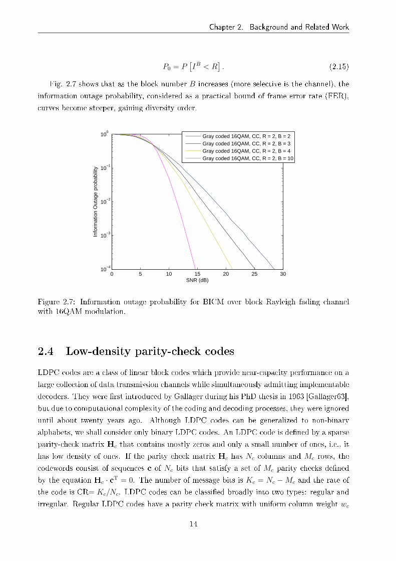
Fig. 2.7 shows that as the block number B increases (more selective is the channel), the
information outage probability, considered as a practical bound of frame error rate (FER),
curves become steeper, gaining diversity order.
0 5 10 15 20 25 3010
−4
10−3
10−2
10−1
100
SNR (dB)
Info
rmat
ion
Out
age
prob
abili
ty
Gray coded 16QAM, CC, R = 2, B = 2Gray coded 16QAM, CC, R = 2, B = 3Gray coded 16QAM, CC, R = 2, B = 4Gray coded 16QAM, CC, R = 2, B = 10
Figure 2.7: Information outage probability for BICM over block Rayleigh fading channelwith 16QAM modulation.
2.4 Low-density parity-check codes
LDPC codes are a class of linear block codes which provide near-capacity performance on a
large collection of data transmission channels while simultaneously admitting implementable
decoders. They were �rst introduced by Gallager during his PhD thesis in 1963 [Gallager63],
but due to computational complexity of the coding and decoding processes, they were ignored
until about twenty years ago. Although LDPC codes can be generalized to non-binary
alphabets, we shall consider only binary LDPC codes. An LDPC code is de�ned by a sparse
parity-check matrix Hc that contains mostly zeros and only a small number of ones, i.e., it
has low density of ones. If the parity check matrix Hc has Nc columns and Mc rows, the
codewords consist of sequences c of Nc bits that satisfy a set of Mc parity checks de�ned
by the equation Hc · cT = 0. The number of message bits is Kc = Nc −Mc and the rate of
the code is CR= Kc/Nc. LDPC codes can be classi�ed broadly into two types: regular and
irregular. Regular LDPC codes have a parity check matrix with uniform column weight wc
14

Chapter 2. Background and Related Work
as well as uniform row weight wr, where the column (row) weight refers to the number of �1�s
in a column (row). In irregular LDPC codes the column and row weight are not constant.
In 1981, Tanner generalized LDPC codes and introduced a graphical representation
[Tanner81], now called Tanner graphs. The Tanner graph is a bipartite graph which de-
scribes the code by two types of nodes (variable and check nodes) and edges connecting two
nodes of di�erent types (see Fig. 2.8).
x1 + x2 + x3 + x4 + x6 + x8 + x10 = 0
x1 + x3 + x4 + x7 + x8 + x9 + x10 = 0
x2 + x4 + x8 = 0
x1 + x5 + x7 + x8 + x9 + x10 = 0
x3 + x4 + x5 + x7 + x9 = 0
x1
x2
x3
x4
x5
x6
x7
x8
x9
x10
Figure 2.8: Tanner graph for an example LDPC code. Round nodes represent variable nodesand square nodes represent check nodes.
Generally, Tanner graphs are a speci�c case of FGs. In Tanner's original formulation, all
variables are codeword symbols and hence �visible�. Wiberg et al. [Wiberg96], introduced
�hidden� state variables and also suggested applications beyond coding. FGs take these graph
theoretic models one step further, by applying them to functions. From the FG perspective
(as we will describe in Section 3.2), a Tanner graph represents a particular factorization of
the characteristic function of a code. Hence, from now on and without loss of generality, we
will refer to Tanner graphs as FGs.
2.4.1 LDPC codes in DVB
The �rst generation of DVB speci�cations use concatenated convolutional and Reed-Solomon
(RS) codes. In the second generation standards, this forward error correction (FEC) tech-
niques have been replaced by LDPC and Bose-Chaudhuri-Hocquegham (BCH) codes. These
codes, which are tens of thousands bits long, can realize a substantial throughput increase
and improve both the performance and the encoding complexity. The well-known extended
irregular repeat-accumulate (eIRA) codes have been adopted for this purpose [Yang04]. The
15

Chapter 2. Background and Related Work
parity-check matrix is of the form
Hc =[H1
(Nc−Kc)×KcH2
(Nc−Kc)×(Nc−Kc)
], (2.16)
where H1 is a submatrix corresponding to information and H2 is a staircase lower triangular
submatrix corresponding to parity:
H2 =
1
1 1
1 1
...
1 1
1 1
(2.17)
Encoding procedure is given by the parity bits calculation as
p1 =Kc∑
k=1
ukh1,k (2.18)
pm = pm−1 +Kc∑
k=1
ukhm,k, (2.19)
where hi,j is the (i, j)th element of parity check matrix Hc, with 1 ≤ i ≤Mc and 1 ≤ j ≤ Nc.
Note that Mc = Nc −Kc. Calculating each parity bit recursively, we can obtain the whole
codeword c using the parity check matrix directly, that is, without the generator matrix.
Since H1 is sparse, encoding has linear complexity with respect to the codeword length.
2.4.2 Decoding algorithms
In addition to introducing LDPC codes, Gallager proposed a near-optimal decoding algo-
rithm. Since then, many research works have proposed similar algorithms, albeit for other
applications. The algorithm iteratively computes the distributions of variables in a graph-
based model, and it is known under di�erent names depending on the context, such as SP,
BP or max-product (MP). We will take the SP algorithm as a reference, but there are
approximations of the SP that are popular for reducing complexity like MS or max-sum
plus-correction factor (MSPCF). A further explanation on iterative algorithms based on
graph models is given in Section 3.2.
With the aim of avoiding numerical instability, it is common to use the logarithmic do-
main version of the SP. Following the graph theory basis, local computations are performed
in the nodes and updated messages are exchanged between variable and check nodes. Af-
ter a �nite number of iterations or after some stopping criteria has been met, the decoder
16

Chapter 2. Background and Related Work
computes the output LLRs from which decisions on the bits ci are made. One example of
such stopping criteria is to stop iterating when cHTc = 0, where c is a tentative decoded
codeword.
cifjrji
qij
Figure 2.9: Message passing in the LDPC decoder. fj represents a variable node and cirepresents a check node.
The logarithmic domain SP decoder is summarized as follows:
1. For i = 1, ..., Nc, initialize L (qij) with channel LLRs L (ci) calculated in (2.11). Note
that index n and m in (2.11) have been replaced by i.
2. Update {L (rji)} using the next equation
L (rji) =∏
i′∈Vj\i
αi′jφ
∑
i′∈Vj\i
φ (βi′j)
, (2.20)
where αij = sign [L (qij)], βij = |L (qij)| and φ (x) = −log [tanh (x/2)] = log(
exp(x)+1exp(x)−1
).
3. Update {L (qij)} using the next equation
L (qij) = L (ci) +∑
j′∈Ci\j
L (rj′i) , (2.21)
4. Update {L (Qi)} using the next equation
L (Qi) = L (ci) +∑
j∈Ci
L (rji) . (2.22)
5. For i = 1, ..., Nc set ci = 1 if L (Qi) < 0 and ci = 0 otherwise. If the stopping criteria
is not ful�lled or the number of iterations is less than the maximum limit go to step
2, else stop.
17

Chapter 2. Background and Related Work
2.5 Time-varying fading channels
In Section 2.2 we have referred to the fading experienced by a signal due to multipath time
delay spread. Depending on the relation between the signal bandwidth and the coherence
bandwidth of the channel (or the delay spread and the symbol period), the channel can be
frequency-�at fading or frequency-selective fading. On the other hand, a wireless channel
can also be characterized by channel time variation induced by relative mobility between
transmitter and receiver, which imposes fundamental limitations on the performance of the
wireless communication systems.
The time-varying nature of the channel is described by the coherence time and the
Doppler spread. The coherence time refers to the time duration over which the channel
impulse response remains essentially invariant, whereas the Doppler spread is the frequency-
domain dual of the coherence time, and describes how much a pure sinusoid is spread out
when it undergoes a mobile channel. On the basis of broadcasting communication scenar-
ios considered in this dissertation, Clarke's model for mobile systems is adopted, where the
transmitter is �xed and the receiver is moving around at a certain speed v as depicted in
Fig 2.10.
Transmitter
Transmitted wave
Ring of scatterers aroundreceiver giving rise to multipath Receiver
kth scatterer
βk
Speed v
Figure 2.10: Clarke's model for time-varying Rayleigh fading channels.
Clarke de�ned a well-known model for channel variations in a typical urban environment
characterized by fast-fading and multipath [Clarke68]. The mathematical model describes a
time-varying complex gain that is a sum of a �nite number of gains of complex exponentials
(scatterers) as
X (t) =∑
k
exp (j (2πfkt+ θk)) , (2.23)
where fk is the Doppler shift su�ered by the kth component. This mathematical model is
represented graphically in Fig. 2.10, where the Doppler spread for each of the components or
scatterers is fk = vFc
ccos βk, where Fc is the carrier frequency, and c denotes the speed of light.
18
Chapter 2. Background and Related Work
The maximum Doppler spread (also called absolute Doppler frequency) is Fd = vFc
c. Based
on the central limit theorem, X (t) can be modeled as a complex Gaussian random process
with zero mean, so that we need to specify the power spectral density. The derivation of the
Clarke power spectral density (sometimes better known as Jakes power spectral density) is
based on the following three assumptions:
1. The propagation of the electromagnetic waves takes place in the two-dimensional (hor-
izontal) plane, and the receiver is located in the center of an isotropic scattering area.
2. The angles of arrival βk are uniformly distributed in the interval [−π, π).
3. The antenna radiation pattern of the receiving antenna is omnidirectional.
The power spectral density is de�ned as
SX (f) =1
πFd
√1−
(fFd
)2|f | ≤ Fd, (2.24)
which is normalized so that
E[|X (t)|2
]=
∫ Fd
−Fd
SX (f) df = 1. (2.25)
The power spectral density is the Fourier transform of the time-domain autocorrelation
function described as RX (τ) = J0 (2πFdτ), where J0 (·) is the zero-order Bessel function
of the �rst kind. The �bowl shape� is the classical shape of this spectrum. The procedure
described above is widely used to model frequency-selective time-varying channels, since each
tap in (2.6) can be thought of as a sum of a number of unresolvable components arriving
from di�erent directions.
It is worth noting that the Doppler power spectral density of far echoes deviates con-
siderably from the Clarke power spectral density and it is better described by the so-called
Gaussian power spectral density:
SX (f) =1
fc
√ln 2
πexp
(− ln 2
(f
fc
)2), (2.26)
where fc is the 3-dB-cuto� frequency. The Gaussian power spectral densities are generally
shifted from the origin of the frequency plane because far echoes mostly dominate from a
certain direction of preference.
After having incorporated the mobility factor to the channel model described in Section
2.2, we can sum up the whole e�ects produced by the channel as follows: the time dispersion
and the frequency dispersion mechanisms (they are independent of each other) in a mobile
radio channel lead to four possible distinct e�ects, which are manifested depending on the
19

Chapter 2. Background and Related Work
nature of the transmitted signal, the channel, and the vehicular speed. Multipath delay
spread leads to time dispersion and frequency-selective fading, whereas the Doppler spread
leads to frequency dispersion and time-selective fading. Consequently, we can identify four
di�erent types of fading:
1. The channel is frequency-�at fading if the bandwidth of the signal is smaller than the
channel bandwidth, or, from the time-domain point of view, the delay spread is smaller
than the symbol period.
2. The channel is frequency-selective if the bandwidth of the signal is bigger than the
channel bandwidth, or, from the time-domain point of view, the delay spread is bigger
than the symbol period.
3. The channel is slow-fading if the coherence time of the channel is bigger than the
symbol period, which happens when the Doppler spread is low.
4. The channel is fast-fading if the coherence time of the channel is smaller than the
symbol period, which happens when the Doppler spread is high.
The scope of this work covers the challenging radio channels where the high vehicular
speed in a multipath environment leads to fast frequency-selective fading, also termed as
double selective fading channels.
2.5.1 Performance degradation of OFDM systems due to Doppler
spreading
As it has been pointed in Section 2.3.2, OFDM yields high spectral e�ciency and reduces the
e�ects of the multipath channel by making the symbol period much larger than the delay
spread of the channel. If 1/Ts is the symbol rate of the input data, the symbol interval
in the OFDM system is increased to NTs, where N is the number of total subcarriers.
Consequently, each subchannel transmits at a bit rate of log2 ΓNTs
bits/s, where Γ refers to the
constellation size. The subcarriers are orthogonal to each other, satisfying
1
NTs
∫ NTs
0
exp (j2πfit) exp (j2πfjt)dt =
1 i = j
0 i 6= j, (2.27)
where fi = i−1NTs
, (i = 1, 2, ..., N). For conventional OFDM receivers, it is assumed that
the channel remains static in an OFDM symbol period. In this case, equalization can be
drastically simpli�ed by turning the frequency-selective channel into several parallel �at-
fading channels, whose channel impulse response hk (t, τ) for the kth subchannel is denoted
as
20

Chapter 2. Background and Related Work
hk (t, τ) = βk (t) δ (τ) , (2.28)
and it is assumed that the processes {βk (t) ,−∞ < t <∞} are complex jointly stationary
and jointly Gaussian with zero means and cross covariance function
Rβk,βl(τ) := E [βk (t+ τ) β∗l (t)] , k, l = 1, ..., N. (2.29)
However, when the channel is time-variant and it varies within an OFDM block, the
subcarriers are not longer orthogonal and the system performance drops down severely. In
fact, it is well-known that one of the main drawbacks of OFDM is its susceptibility to the loss
of orthogonality among subcarriers due to Doppler frequency shifts (i.e., mobile reception)
or oscillator o�sets, which lead to the so-called ICI. If it is not compensated, the ICI will
result in an error �oor. It is widely assumed in the literature [Wang06] that the correlation
function expressed in (2.29) has the following factorable form
Rβk,βl(τ) = R1 (τ)R2 (k − l) , (2.30)
which is su�cient to represent both the frequency-selectivity and the time-varying e�ects of
the channel. R1 (τ) is the same autocorrelation function de�ned in the previous section which
describes the temporal correlation and is identical for all subchannels. The corresponding
power spectral density is modeled by the Jakes' spectrum (2.24). On the other hand, R2 (k)
represents the correlation in frequency across subcarriers and is conditioned by the power
pro�le of the channel impulse response and the subcarrier spacing ∆f = 1NTs
. Throughout
this dissertation, we will assume that the delay spread of the channel is much smaller than
the CP duration, and therefore, the received signal is not a�ected by ISI.
2.5.1.1 Intercarrier interference
We now turn our attention to describing the ICI. Let us represent the channel impulse
response in discrete form as hn,l for the lth channel tap and nth time instant, so that the
channel can be approximated by an equivalent, discrete-time, baseband model. The received
signal in time-domain (before applying the discrete Fourier transform (DFT)), under the
e�ect of time-varying fading channel and AWGN is given by
rn =L−1∑
l=0
hn,lxn−l + zn, (2.31)
where x is the transmitted signal in time-domain (after applying the inverse discrete Fourier
transform (IDFT)), and z is the AWGN. Demodulation implies taking DFT of the received
block after removing the CP to get [y0, y1, ..., yN−1]T . The demodulated signal at the kth
21

Chapter 2. Background and Related Work
tone becomes
yk =1√N
N−1∑
n=0
rne−j2πnk/N =
1√N
N−1∑
n=0
L−1∑
l=0
hn,lxn−le−j2πnk/N +
N−1∑
n=0
zne−j2πnk/N . (2.32)
This on solving yields
yk =N−1∑
m=0
Hk,msm + zk = gksk +N−1∑
m=0,m 6=k
Hk,msm + zk, (2.33)
where H is the N × N frequency response of the channel, s is the transmitted signal in
frequency-domain, gk = Hk,k represents the gain of the desired symbol, and zk is the noise
on the kth subcarrier which has the same statistics as the noise in time-domain. The second
term on the right hand side in (2.33) describes the ICI a�ecting the yk received symbol,
where
Hk,m =1
N
N−1∑
n=0
Hn,mej2π(m−k)n/N , (2.34)
and Hn,m is the time-varying frequency response of the channel, de�ned as
Hn,m =1√N
∑hn,le
−2πml/N 0 ≤ m ≤ N − 1. (2.35)
From 2.33, it is clear that each of the received symbols yk has information of all the
transmitted symbols s. In other words, due to the Doppler spread, the transmitted symbols
s are modulated in all the subcarriers with di�erent weights de�ned by the H matrix, giving
rise to a new form of frequency-diversity. Let focus on the H matrix, which will be used to
exploit the frequency-diversity given by the ICI in further sections. It is worth noting that
when the channel is time-invariant the frequency response matrix is diagonal, which means
that the o�-diagonal elements describing the ICI become zero. This fact makes possible
the low complexity per-subcarrier equalization that characterizes OFDM systems. However,
when the channel is time-variant, the o�-diagonal elements of H are not longer zero, which
makes necessary to cope with high complexity detection.
Fig. 2.11a and 2.11b show the �rst 100 samples of H and H respectively. As it can
be seen, H re�ects the variation of the channel over time and frequency, while H shows
that although the H matrix is not diagonal, most of the energy is concentrated around the
main diagonal, where higher power is represented by lighter color. For example, more than
the 64% of the energy is located in the three main neighboring subcarriers for normalized
Doppler frequency fd = 0.13, where the normalized Doppler is de�ned as fd = Fd/∆f and
∆f refers to the subcarrier spacing. As a result of increasing the vehicular speed, or the
22

Chapter 2. Background and Related Work
OFDM block size, more energy leaks into the o�-diagonal elements of H, increasing the ICI
power that a�ects each subcarrier as it is shown in Fig. 2.12.
0 20 40 60 80 1000
10
20
30
40
50
60
70
80
90
100
Frequency samples
Tim
e sa
mpl
es
0
10
20
30
40
50
60
70
80
90
1000 20 40 60 80 100
Subcarriers
Sub
carr
iers
(a) (b)
Figure 2.11: Representation of the time-varying frequency response of the channel H (a)and the frequency response matrix H describing the ICI power distribution (b). fd = 0.8and TU6 channel has been considered.
Frequency
|H|
Frequency
|H|
(a) (b)
Figure 2.12: The main three diagonals of H for fd = 0.1 (a) and fd = 0.4 (b). The blue linerepresents the main diagonal, and the red one and the green one represent the �rst diagonalon the right side and the �rst diagonal on the left side, respectively.
Russel and Stüber [Russell95] derived the ICI power as
PICI = Es −EsN2
{N + 2
N−1∑
i=1
(N − i) J0 (2πFdTsi)
}, (2.36)
where∑L−1
l=0 E[|hn,l|2
]= 1 has been assumed. Note that the degradation due to ICI is only
a function of Es, N , Ts and Fd, and is independent of the signal constellation. That is to
23

Chapter 2. Background and Related Work
say, apart from signal power criteria, the ICI power is determined by the normalized Doppler
frequency fd.
For N su�ciently large, the central limit theorem can be invoked and the ICI can be
modeled as an additive Gaussian random process leading to an error �oor determined ana-
lytically by means of the normalized Doppler frequency [Russell95]. In [Wang06], it is proven
that, for conventional modulation methods, such as phase-shift keying (PSK) and QAM, the
bivariate probability density function (PDF) of the ICI is shown to be a weighted Gaussian
mixture. Fig. 2.13 depicts the histogram of the LLRs at the input of the decoder a�ected by
ICI, where it is clearly shown that it presents a Gaussian-like distribution centered around
zero.
−60 −40 −20 0 20 40 600
1
2
3
4
5
6
7
8x 10
4
Figure 2.13: Histogram of the LLRs a�ected by ICI.
2.5.2 Exploiting time-domain diversity
Most of wireless communication standards make use of symbol interleavers. In this section,
the attributes of a symbol interleaver in mobile scenarios are described. For that purpose, the
time interleaver of the DVB-T2 standard is taken as reference. The primary bene�t of this
time interleaver is to provide time-diversity when used along with error correction coding. If
the interleaver time span TIL is much larger than the coherence time of the channel TC , there
is a great chance that contiguous symbols are subjected to uncorrelated fading values, which
leads to achieve e�ective diversity. Therefore, it is of interest to enlarge the ratio TIL/TC .
Moreover, although communications degrade as the vehicle speed increases (the channel
becomes more selective), the bene�t of an interleaver can be higher for higher vehicular
speeds. However, in a real-time communication system, there should be a maximum limit
24

Chapter 2. Background and Related Work
of this ratio in order to limit the time delay associated with the interleaver.
Fig. 2.14 shows the e�ect of the time interleaver in a DVB-T2 signal transmission over a
multipath channel pro�le with 100 Hz of Doppler frequency where di�erent time interleaving
depths (time span) have been adopted. When the interleaving depth is set to 1 FEC block,
the BER curve tends to the typical error �oor due to Doppler spreading. However, increasing
the interleaving depth leads to a substantial enhancement of system performance, removing
the error �oor, and thus, making it possible to have an acceptable communication quality.
The time interleaving, in conjunction with LDPC codes, makes the DVB-T2 speci�cation
very robust in a wide range of mobile communication scenarios.
5 10 15 20 25 3010
−6
10−5
10−4
10−3
10−2
10−1
100
SNR (dB)
BE
R
1 FEC block interleaving depth5 FEC block interleaving depth10 FEC block interleaving depth
Figure 2.14: DVB-T2 signal transmission over multipath channel pro�le with 100 Hz ofDoppler frequency. 16QAM and CR= 2/3 is considered.
Take not that, throughout this work, the amount of bits to be simulated in BER vs SNR
simulations (max trials) has been calculated as follows
max trials =arbitrary amount of errors to be assumed
target BER× CR(2.37)
where the arbitrary amount of errors to be assumed is set to 100, and the target BER is
usually 10−5. The BER will be measured at the output of the inner decoder.
2.6 Terrestrial digital television
Television services can be delivered through di�erent means of transmission. Nowadays,
there coexist three main television networks: satellite, cable and terrestrial. The last one is
25

Chapter 2. Background and Related Work
one of the most extended since the direct evolution of the analogue television yielded the
popularity of its digital counterpart. Several standards of terrestrial digital television (DTV)
are adopted all around the world, being the following four considered the most important:
the American advanced television system committee (ASTC) [ATSC05], the Japanese in-
tegrated services digital broadcasting-terrestrial (ISDB-T) [ARIB01], the Chinese digital
terrestrial multimedia broadcast (DTMB) [SAC06] and the European DVB-T [ETSI97]. In
this work, we are going to focus on the European standards, namely on the second generation
of terrestrial DVB speci�cations: DVB-T2 [DVB08] and Digital Video Broadcasting-Next
Generation Handheld (DVB-NGH). A decade after having published the �rst generation
DVB standards, the second generation terrestrial counterpart was issued, which thanks to
novel signal processing techniques, has noteworthy increased robustness and spectral e�-
ciency comparing with its predecessor. Recently, the DVB consortium has issued a Call
for Technologies for DVB-NGH with the aim of providing an advanced mobile broadcasting
system.
2.6.1 DVB-T2
Based on recent research results and a set of commercial requirements, the DVB consortium
concluded that there were suitable technologies which could provide increased capacity and
robustness in the terrestrial environment, mainly for high de�nition television (HDTV) trans-
mission. Therefore, a new standard named DVB-T2 has been designed primarily for �xed
receptors, although it must allow mobile reception in certain conditions with the same spec-
trum characteristics as DVB-T. Fig. 2.15 shows the main stages of a DVB-T2 transmitter,
where dashed lines represent optional blocks.
MPEG
transport
stream
BCH/LDPC
ENCODERBit interleaver
Bits to cell
symbol
mapping
Constellation
rotation
Cell
interleaver
Frecuency
interleaver
STBC
MISOPilot insertionIFFT
Guard
interval
insertion
Modulation
and RF
transmission
Time
interleaver
OFDM
frame
adaptation
Figure 2.15: Elementary transmission chain of DVB-T2.
Considering the physical layer, the digital data sequences, which contain moving pic-
ture experts group (MPEG) video, audio and other information streams, are transmitted
using OFDM modulation. The �rst remarkable novelty comparing with DVB-T lies on the
error correction strategy, since DVB-T2 uses the same channel codes that were designed
for DVB-S2. The coding algorithms, based on the serial concatenation of LDPC and BCH
codes, o�er excellent performance, resulting in a very robust signal reception. LDPC-based
FEC techniques can o�er a signi�cant improvement compared with the convolutional error
26

Chapter 2. Background and Related Work
correcting scheme used in DVB-T. Regarding the modulation, as it has been already men-
tioned, DVB-T2 uses the same OFDM technique as DVB-T. Maintaining the 2K and 8K
modes, the new standard has introduced longer symbols with 16K and 32K carriers in order
to increase the length of the GI without decreasing the spectral e�ciency of the system. The
new speci�cation o�ers a large set of modulation parameters by combining di�erent numbers
of carriers and GI lengths, making it a very �exible standard as it is shown in Fig. 2.16.
Furthermore, the highest constellation size has been increased to 256 symbols.
DVB-T DVB-T2
Convolutional + Reed-Solomon
LDPC + BCH FEC
1/2, 2/3, 3/4, 5/6, 7/8 1/2, 3/5, 2/3, 3/4, 4/5, 5/6
Modes QPSK, 16QAM, 64QAM QPSK, 16QAM, 64QAM, 256QAM
Guard intervals ¼, 1/8, 1/16, 1/32 1/4, 19/256, 1/8, 19/128, 1/16, 1/32, 1/128
FFT size 2K, 8K 1K, 2K, 4K, 8K, 16K, 32K
Scattered pilots 8% of total 1%, 2%, 4% and 8% of total
Continual pilots 2.6% of total 0.35% of total
Figure 2.16: Available modes in DVB-T and DVB-T2.
On the other hand, a new technique called rotated constellations and Q-delay (RQD)
is provided as optional, which comes to o�er additional robustness and diversity in chal-
lenging terrestrial broadcasting scenarios. Furthermore, a mechanism has been introduced
to separately adjust the robustness of each delivered service within a channel in order to
meet the required reception conditions (in-door antenna/roof-top antenna, etc.). DVB-T2
also speci�es a transmitter diversity method, known as Alamouti coding, which improves
coverage in small scale single frequency networks (SFN)s.
Finally, the DVB-T2 standard takes into account one of the main drawbacks of OFDM,
the peak-to-average power ratio (PAPR) of the signal and its e�ects on the transmitter
equipments. High power peaks are usually generated by OFDM transmission leading to
distortions at the ampli�ers, thus minimizing their e�ciency. Two techniques have been
included in the standard to limit the PAPR without degrading the transmitted signal: carrier
reservation and active constellation extension. The former reserves some subcarriers that
can be used to correct the PAPR level of the transmitted signal whereas the latter achieves
the same e�ects modifying the QAM constellation without degrading the signal recovery at
reception.
Fig. 2.17 shows the comparative performance of DVB-T and DVB-T2 for similar com-
munication parameters. In order to allow a fair comparison of both standards, quasi error
free (QEF) reception is considered, which is de�ned by BER= 2 · 10−4 and BER= 1 · 10−7 at
the output of the inner decoder for DVB-T and DVB-T2, respectively. If these QEF refer-
27

Chapter 2. Background and Related Work
ence values are analyzed, a gain of 6 dB can be established between the two standards over
AWGN channel and nearly 4 dB over Rayleigh channel. The code rates have been selected
in order to approach equivalent data rates.
11 12 13 14 15 16 17 18 19 2010
−8
10−7
10−6
10−5
10−4
10−3
10−2
10−1
100
SNR (dB)
BE
R
DVB−T2 64QAM CR 3/5DVB−T 64QAM CR 2/3
14 16 18 20 22 24 26 28 3010
−7
10−6
10−5
10−4
10−3
10−2
10−1
100
SNR (dB)
BE
R
DVB−T2 TU6 64QAM CR 3/5DVB−T TU12 64QAM CR 2/3
(a) (b)
Figure 2.17: BER performance of DVB-T and DVB-T2 systems over AWGN (a) and Rayleigh(b) channels.
The DVB-NGH standard on the other hand, will be the system for DTV signal reception
on mobile handsets. DVB-NGH starts from DVB-T2, already designed in order to cor-
rectly operate in the mobile environment, and investigates the possibility of adopting new
technologies for the mobile scenario. The new standard is expected to be �nished by 2013.
2.6.2 Multipath channel models for terrestrial television
Radio channel models are usually derived from �eld measurements of the channel parameters
in reference scenarios. This allows to create realistic models according to the reception envi-
ronment under study (e.g. outdoor, indoor, etc.). In DTV, due to the variety of scenarios,
multiple models have been used to assess the performance at the receiver. Terrestrial DTV
standards, such us DVB-T or DVB-T2, de�ne several channel models to provide simulated
performance results. The DVB-T2 implementation guidelines document [DVB09] proposes
several channel models. In this dissertation, two channel models have been chosen to analyze
the performance of the proposed detection techniques in mobile conditions: COST 207 TU6
and 6-tap typical rural area (RA6) channels [COST20789]. These channel models were orig-
inally designed for global system for mobile communication (GSM) and adapted to mobile
DVB-T. In fact, TU6 is one of the most extended channel models for simulation tests in
terrestrial DTV. The Doppler spreading e�ect is modeled by the Doppler power spectral
densities SX (f) for each of the paths.
The TU6 channel models an urban environment with re�ections from buildings without
LOS. Assuming the sample frequency of DVB standards, the impulse response has 47 taps
28

Chapter 2. Background and Related Work
from which only six present signi�cant power. It consists of a frequency-selective Rayleigh
channel model. On the other hand, the RA6 channel models a typical rural non hilly ter-
rain, which leads to a less frequency-selective response than the TU6 model's. It considers
both LOS and non line-of-sight (NLOS) resulting in Rayleigh and Ricean channel models,
respectively. The Doppler power spectral densities and the path characteristics are de�ned
in the COST 207 project [COST20789].
2.7 The turbo principle in mobile communications
The 'turbo principle' is a general principle in decoding and detection which can be applied
to many detection/decoding problems. It refers to a standard set of rules for exchanging
and updating soft decision information between locally optimal processors. It was originally
proposed by Berrou and Glaviex [Berrou93] in the early 1990s for suboptimal decoding of
�turbo codes� and extended to many detection, decoding and estimation problems soon
afterwards. Strictly speaking, there is nothing 'turbo' in the transmitter. Only the receiver
uses the 'turbo' feedback. In almost all the cases, the system can be described as a serial
concatenation of two decoders, as it is depicted in Fig. 2.18.
Decoder II∏−1
cn,mLE(cn,m)
Decoder I
∏ LD(cn,m)LAII(cn,m)
From the channel
LAI(cn,m)
Figure 2.18: Example of a turbo receiver.
The crucial point at the receiver is that the two detectors/decoders are soft-in/soft-
out (SISO) processors that accept and deliver probabilities or soft values. The extrinsic part
of the soft output of one decoder LD (cn,m) is passed on to the other decoder to be used as a
priori input LAII(cn,m). We can conclude that, the elements participating in every iterative
(turbo) process are the next ones: concatenation of component blocks, interleavers, SISO
process and the exchange of extrinsic information. Table 2.1 summarizes di�erent turbo
schemes based on serial concatenated systems.
Note that in a wireless communication system the inner 'encoder' could be the multipath
channel, or in the case of a mobile OFDM system, as it will be described in Chapter 4,
the channel a�ected by ICI. In this cases, SISO detectors are useful in the design of many
wireless systems. In fact, such detectors, when concatenated with a soft channel decoder,
can signi�cantly improve the quality of wireless transmission by performing joint, iterative
29

Chapter 2. Background and Related Work
con�guration en-/decoder I en-/decoder IIserial code concat. FEC en.-/dec. FEC en./dec.turbo equalization FEC en.-/dec. Multi. chan./det.
turbo BICM FEC en.-/dec. Mapper/demap.turbo MIMO FEC en.-/dec. Mapper/MIMO det.
turbo source-channel source encoder FEC en.-/dec.LDPC code/decoder check nodes variable nodes
Table 2.1: Serial concatenated systems with iterative detection/decoding.
data detection and channel decoding through the exchange of soft information. However,
the exponential complexity of the optimal MAP detector rapidly becomes prohibitive. This
motivates the design of suboptimal soft detectors whose complexities are scalable with system
dimensions. One recent trend, as it is the scope of this research work, is to design soft
detectors for time-varying channels to enable joint channel estimation, data detection, and
decoding.
2.7.1 BICM-ID
The implementation guidelines document of DVB-T2 [DVB09] proposes the turbo BICM or
the so-called bit-interleaved coded modulation-iterative demapping (BICM-ID) as optional
reception strategy. It consists of assisting the soft demapping process by considering the
extrinsic data at the output of the LDPC decoder as a priori information. The demapping
equation (2.11) has been modi�ed to include a priori input as follows,
LD (cn,m) = log
∑∀cn:cn,m=0 p (yn|sn)
∏Mj=1 P (cn,j)
∑∀cn:cn,m=1 p (yn|sn)
∏Mj=1 P (cn,j)
+ logP (cn,m = 0)
P (cn,m = 1). (2.38)
Iterative demapping and decoding strategies have been analyzed for the �rst generation DVB
systems and DVB-S2 in [Su�ritti07] and [Lee01] respectively. In Fig. 2.19, performance of
DVB-T2 is assessed over a TU6 channel employing iterative demapping. 64800 bit-length
LDPC codes have been used and 20 LDPC iterations have been carried out in each of the 3
turbo iterations. In the non-iterative case, 50 LDPC iterations have been carried out.
Fig. 2.19 shows a performance gain of about 0.5 dB of SNR for both 16QAM and 64QAM
constellations at BER=1 · 10−4. As it is explained in Section 2.3.1, there is a capacity gap
between CM and BICM that is negligible when Gray mapping is used. As it is pointed out
in [Xie09], such gap decreases as the coding rate increases, and increases as the constellation
order increases. Iterative demapping can help to regain such loss. In line with this statement,
it can be appreciated a slightly higher performance gain in 64QAM than in 16QAM.
30

Chapter 2. Background and Related Work
10 10.5 11 11.5 12 12.5 1310
−5
10−4
10−3
10−2
10−1
SNR (dB)
BE
R
16QAM CR 2/316QAM CR 2/3 ID (3 turbo iterations)64QAM CR 1/2 64QAM CR 1/2 ID (3 turbo iterations)
Figure 2.19: DVB.T2 performance with iterative demapping over the TU6 channel. Inthe iterative case, 3 turbo iterations are considered and 20 LDPC iterations in each turboiteration. In the non-iterative case, 50 LDPC iterations are carried out.
2.8 Intercarrier interference cancellation schemes
In recent years, a wide range of OFDM receiver designs have been proposed in the lit-
erature for time-varying multipath channels. We can make a di�erence between linear
equalizers based on zero-forcing (ZF) [Hsu09] or minimum mean-square error (MMSE) cri-
teria [Rugini06, Huang07, Fang08], and non-linear equalizers based on ICI cancellation or
decision-feedback [Zhao01, Cai03, Tomasin05, Hou05, Li10, Taubock11]. Linear equalization
requires the inversion of the frequency channel matrix, which is prohibitively complex for
large OFDM symbols. Although many approaches have been proposed for solving this prob-
lem [Fang08, Hsu09], they show, in general terms, poor performance at high-mobility sce-
narios. Non-linear equalizers outperform linear approaches at the cost of higher complexity.
Since there are similarities between the ICI and the multiuser interference (MUI), well-known
interference cancellation techniques, such as, successive interference cancellation (SIC) and
parallel interference cancellation (PIC), can be directly applied to ICI suppressing. While the
former present higher computational complexity and processing delays, the latter su�er from
performance loss at high Doppler frequencies. In [Hwang09], a combination of the MMSE
method and PIC is presented, which outperforms the conventional PIC schemes. Recently,
space alternating generalized expectation maximization (SAGE) has been proposed for ICI
cancellation [Panayirci10, Wu11].
31
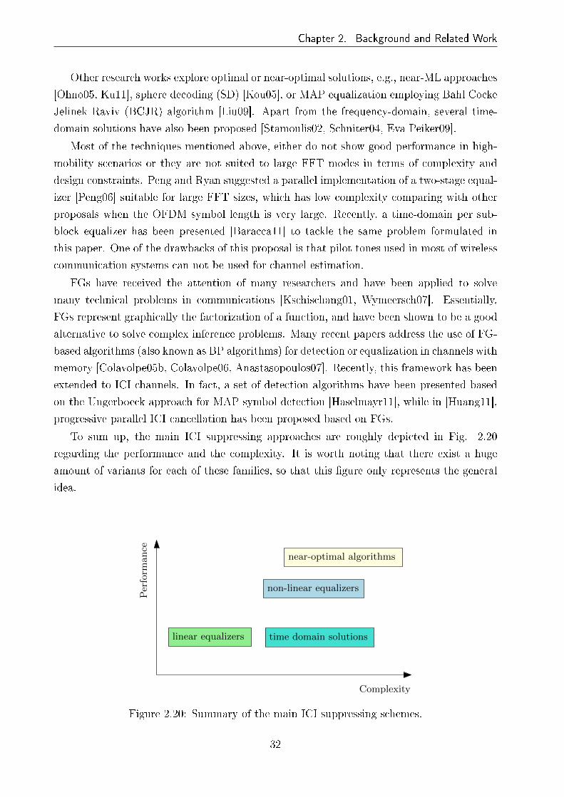
Chapter 2. Background and Related Work
Other research works explore optimal or near-optimal solutions, e.g., near-ML approaches
[Ohno05, Ku11], sphere decoding (SD) [Kou05], or MAP equalization employing Bahl Cocke
Jelinek Raviv (BCJR) algorithm [Liu09]. Apart from the frequency-domain, several time-
domain solutions have also been proposed [Stamoulis02, Schniter04, Eva Peiker09].
Most of the techniques mentioned above, either do not show good performance in high-
mobility scenarios or they are not suited to large FFT modes in terms of complexity and
design constraints. Peng and Ryan suggested a parallel implementation of a two-stage equal-
izer [Peng06] suitable for large FFT sizes, which has low complexity comparing with other
proposals when the OFDM symbol length is very large. Recently, a time-domain per sub-
block equalizer has been presented [Baracca11] to tackle the same problem formulated in
this paper. One of the drawbacks of this proposal is that pilot tones used in most of wireless
communication systems can not be used for channel estimation.
FGs have received the attention of many researchers and have been applied to solve
many technical problems in communications [Kschischang01, Wymeersch07]. Essentially,
FGs represent graphically the factorization of a function, and have been shown to be a good
alternative to solve complex inference problems. Many recent papers address the use of FG-
based algorithms (also known as BP algorithms) for detection or equalization in channels with
memory [Colavolpe05b, Colavolpe06, Anastasopoulos07]. Recently, this framework has been
extended to ICI channels. In fact, a set of detection algorithms have been presented based
on the Ungerboeck approach for MAP symbol detection [Haselmayr11], while in [Huang11],
progressive parallel ICI cancellation has been proposed based on FGs.
To sum up, the main ICI suppressing approaches are roughly depicted in Fig. 2.20
regarding the performance and the complexity. It is worth noting that there exist a huge
amount of variants for each of these families, so that this �gure only represents the general
idea.
linear equalizers
non-linear equalizers
Complexity
near-optimal algorithms
time domain solutions
Perform
ance
Figure 2.20: Summary of the main ICI suppressing schemes.
32

Chapter 2. Background and Related Work
ICI mitigation has been also considered for the �rst generation DVB standards [Leif07,
Poggioni09], and recently a novel approach has been proposed for DVB-T2 and DVB-NGH
signal reception [Baracca11], where a pre-equalizer operating in sub-blocks of the received
OFDM block was proposed in order to combat the time-variation of the channel caused by
the Doppler frequency shift.
2.9 Chapter Summary
This chapter covers a background of the main theoretical aspects behind this dissertation.
The BICM-OFDM communication framework has been brie�y described, along with LDPC
codes. This communication scheme, sometimes better known as bit-interleaved LDPC coded
modulation (BILCM), has been adopted in many last-generation wireless communication
standards, as it is the case of the second generation terrestrial DTV systems. We also coped
with the challenge of signal reception in mobile environments, and analyzed how an OFDM
signal can be deteriorated by the Doppler spread. The main characteristics of DVB-T2
standard have also been described.
On the other hand, we have introduced the 'turbo principle' and iterative receivers, which
are the key points of the FG framework. We have discussed a particular case of a turbo
receiver (BICM-ID) and analyzed its application in DVB-T2 reception. Last, a summary of
the main ICI suppressing schemes developed in recent years has been presented, emphasizing
ICI suppressing schemes applied to terrestrial DVB systems.
33

Chapter 3
Factor graph-based detection for
channels a�ected by ICI
3.1 Introduction
FGs and the associated summary propagation algorithms are a general trend in signal pro-
cessing, since they present very attractive properties for a wide variety of detection and
estimation problems. First of all, they are simple and easy to read in the sense that they
allow to represent graphically a bunch of equations. Second, they compute marginals in a
mathematically e�cient way. Last, but not least, they allow hierarchical modeling and func-
tional decomposition (we can abstract away parts of the function by grouping some parts
of the graph into a super-vertex), and they are fully compatible with conventional block
diagrams.
The SP algorithm was invented by Gallager [Gallager63] as a decoding algorithm for
LDPC codes. Afterwards, Tanner proposed a graphical model to describe and generalize
LDPC codes, introducing the MS algorithm [Tanner81]. However, the full power of iterative
processing was realized when turbo codes came about [Berrou93] followed by the rediscovery
of LDPC codes [MacKay99]. The remarkable work of Wiberg et al. [Wiberg96] provided
a new perspective by which means decoding of LDPC codes, turbo codes, as well as the
forward-backward (FB) and Viterbi algorithm were viewed as particular instances of the
same algorithm. This made new applications like signal detection for channels with mem-
ory obvious. It is noteworthy that the literature in this framework is vast, and the brief
overview provided here is incomplete, since important contributions have been made from
many di�erent �elds such as arti�cial intelligence, statistics or computer sciences.
But, why use FGs for ICI compensation? Which are the bene�ts of FG-based detection
in DVB terrestrial systems? As it will be explained in further sections in this chapter, the
physical layer of DVB terrestrial systems present two main characteristics that have to be
taken into account for designing the detection strategy: �rst, a powerful channel code is
employed which requires soft detection; second, making use of large OFDM symbol lengths
34

Chapter 3. Factor graph-based detection for channels a�ected by ICI
forces to adopt parallel detection schemes in order to diminish high latencies. FG-based
detection �ts both requirements.
3.2 Basic concepts
A FG is a bipartite graph which describes the factorization of a global function into a
product of several local functions. Running a summary propagation algorithm in the FG
allows to compute marginals of the global function by passing �messages� along the edges of
the graph. The main summary propagation algorithms are the SP algorithm and the MP
(or MS) algorithm. Originally, FGs were proposed in coding theory, but they consist of an
attractive solution for a wide variety of signal processing problems. In fact, HMMs (with
the associated FB algorithm), Kalman �ltering, the Viterbi algorithm (VA), or even the fast
Fourier transform (FFT) can be considered as particular instances of the SP algorithm.
3.2.1 Factor graphs and inference
In this dissertation, FGs are used for solving a well-de�ned inference problem, which is
namely an estimation problem. Let us abstract out the OFDM modulation and consider the
signal in frequency-domain (before and after the inverse fast Fourier transform (IFFT) and
FFT processing, respectively), as shown in the system model described in Fig. 3.1.
Discrete modulator Decision
channel
P (y|s, θ)cn,m sn yn sn
Figure 3.1: Simpli�ed discrete channel model, where neither OFDM modulation nor inter-leaving has been considered for simplicity.
The modulator formats the messages for transmission over the vector channel by trans-
lating the encoded bits cn,m into a N-dimensional vector s composed of symbols chosen from
a complex constellation χ. The conditional probability of the output vector y given the input
vector s, P (y|s), completely describes the discrete version of the channel. The decision de-
vice (in our case, the FG based detector) then translates the output vector y into an estimate
of the transmitted message s. The optimal data detector chooses sn to minimize the error
probability, which is accomplished by the MAP detection strategy de�ned by the Bayesian
estimation theory, where there is a variable of interest (unknown variable) s = [s1, s2, ..., sN ],
an evidence or observation y = [y1, y2, ..., yN ], and an underlying model θ which somehow
describes the relation between s and y:
35

Chapter 3. Factor graph-based detection for channels a�ected by ICI
P (s,y|θ) = P (s|y, θ)P (y|θ) = P (y|s, θ)P (s|θ) . (3.1)
P (s|y, θ) is referred as the posterior probability of s, P (y|θ) is the likelihood of θ, P (y|s, θ)is the likelihood of s given θ, and P (s|θ) is called the a-priori probability, or the prior of
s. Within the MAP detection strategy, two variants can be de�ned depending on the error
parameter to be minimized:
1. MAP sequence detection which minimizes the error rate of the packet s, which means
minimizing the FER:
s = arg maxs
P (s|y) (3.2)
2. MAP symbol detection which minimizes the error rate of the individual symbols sn,
which means minimizing the symbol error rate (SER):
sn = arg maxsn
P (sn|y) (3.3)
In most communication systems, the objective is to maximize over all s. The problem
is that its complexity is exponential with the length of s, which is usually prohibitively
complex. The solution is to minimize the SER (which implies minimizing the BER), instead
of minimizing the FER. But, again, there is a complexity challenge in computing P (sn|y).
It is in this point where FGs gain relevance, since P (sn|y) is marginal of P (s|y), and FGs
can help in computing marginals. From an statistical inference point of view, there are
di�erent problems which could be solved by FGs, but we are going to focus on the subject
of interest in this dissertation, which, as mentioned, is the calculation of the marginal a
posteriori probabilities expressed as,
P (sn|y, θ) =∑
∼{sn}
P (s|y, θ) . (3.4)
where ∼ {sn} refers to all variables except sn.
3.2.2 Building a factor graph
As mentioned, a FG is a diagram that represents the factorization of a function of several
variables. Suppose that some function f (s1, s2, ..., sN) is factorized into J factors,
f (s1, s2, ..., sN) =J∏
k=1
fk (ψk) , (3.5)
where ψk ⊆ {s1, ..., sD} is the kth variable subset and fk (·) is a real valued function. The
factor graph G = (V,E) corresponding to (3.5) is created following the next rules:
36

Chapter 3. Factor graph-based detection for channels a�ected by ICI
• For every variable sn, we create a vertex referred as variable node: sn ∈ V , where Vrepresents the set of vertices of the graph,
• For every factor fk, we create a vertex referred as function node: fk ∈ V , and
• For each factor fk, and every variable sn ∈ ϑ (fk), we create and edge e = (sn, fk) ∈ E,where E is the set of edges, and ϑ (v) stands for the set of neighbors of a given node v.
Once we have factorized the function, we can draw the corresponding FG. Note that there
is a one-to-one mapping between a given factorization and the corresponding FG. The
representation adopted in this research work, which is shown in Fig. 3.2, corresponds to
the conventional FG-type. There is another type of graph introduced by Forney [Forney01]
which is considered as a �normal FG�. Both types are equivalent in the sense that exactly
the same messages are computed, but di�er in some graphical aspects.
f1
f2
f3
s1
s2
s3
s4
Figure 3.2: FG representing function f (s1, s2, s3, s4) = f1 (s1) f2 (s1, s2, s3) f3 (s3, s4).
Our goal is to compute marginals of the function f (·) with respect to N variables. The
marginal of sn is given by
gsn (sn) =∑
∼{sn}
f (s1, s2, ..., sN) , (3.6)
This means that the marginalization of sn involves the summation over the values of all
the variables except sn, which is a cumbersome computational task. Making use of the
factorization in (3.5) and running the SP algorithm in the corresponding FG allows to
compute the N marginals in a computationally attractive way by passing messages over the
edges of the graph. Note that applying the SP algorithm in a FG means local computation
in basic blocks: once we have identi�ed the local processing rule, we only have to remind the
SP rule. The intrinsic bene�ts of this approach are, actually, the reason of the wide usage of
FGs by the digital communication community. In fact, as mentioned, well-known algorithms
such as VA or FB algorithms can be cast to the FG framework in a very natural way.
37

Chapter 3. Factor graph-based detection for channels a�ected by ICI
3.2.3 SP algorithm
The SP algorithm computes two messages for each edge in the graph, one in each direction.
Considering the FG de�ned as in the previous section, we can distinguish two types of
messages: the ones going from a variable node to a function node µsn→fl (sn), and the ones
from a function node to a variable node µfk→sm (sm).
fks2 sm
s3
s1
µs2→fk (s2)
µfk→sm (sm)
µs1→fk (s1)
µs3→fk (s3)
snf2 fl
f3
f1
µf1→sn (sn)
µf3→sn (sn)
µf2→sn (sn)
µsn→fl (sn)
(a) (b)
Figure 3.3: The SP algorithm: message computation rule from function node fk to variablenode sm (a), and from variable node sn to function node fl (b).
There are three phases in the SP algorithm: initialization, message computation and
termination. For convenience, we will start the algorithm from the leaves:
Inizialization:
• Every leaf function node fk, with {sm} = ϑ (fk), sends a message to variable node sm,
with µfk→sm (sm) = fk (sm).
• Every leaf variable node sn, with {fl} = ϑ (sn), sends a message to function node fl,
with µsn→fl (sn) = 1.
Message computation:
• Every function node fk of degree D has received incoming messages from D−1 distinct
variable nodes sn ∈ ϑ (fk). Then, node fk computes the outgoing message µfk→sm (sm)
as
µfk→sm (sm) =∑
∼{sm}
fk
({sn}sn∈ϑ(fk)
) ∏
sn∈ϑ(fk)\{sm}
µsn→fk (sn) . (3.7)
Message propagation is depicted in Fig. 3.3a.
• Every variable node sn of degree D has received incoming messages from D−1 distinct
function nodes fk ∈ ϑ (sn). Then, node sn computes the outgoing messages µsn→fl (sn)
38

Chapter 3. Factor graph-based detection for channels a�ected by ICI
as
µsn→fl (sn) =∏
fk∈ϑ(sn)\{fl}
µfk→sn (sn) (3.8)
Message propagation is depicted in Fig. 3.3b.
Termination:
• The algorithm terminates computing the marginal of sn by multiplying the messages
in both direction on the edge (sn, fk),
gsn (sn) = P (sn,y) = µfk→sn (sn)µsn→fk (sn) . (3.9)
• From the Bayesian estimation theory, and taking into account that
P (y) =∑
sn∈χ
P (sn,y) , (3.10)
the marginal a posteriori distributions, necessary to evaluate the MAP symbol detec-
tion rule, are given by
P (sn|y) =P (sn,y)
P (y)=
gsn (sn)∑sn∈χ gsn (sn)
. (3.11)
3.2.4 Messages and their representation
When FGs are used to solve inference problems, there is usually a common problem related
to the dynamic range of the messages: they tend to get smaller as the algorithm proceeds.
This turns out to be a real problem in computer simulation or hardware implementation.
To get around this problem, it is a common approach to implement the SP algorithm in
logarithmic-domain, which yields an increase of the dynamic range, and therefore makes the
algorithm more stable. In such case, expressions in (3.7) and (3.8) become
µfk→sm (sm) = ln
∑
∼{sm}
exp
ln fk
({sn}sn∈ϑ(fk)
)+
∑
sn∈ϑ(fk)\{sm}
µsn→fk (sn)
, (3.12)
and
µsn→fl (sn) =∑
fk∈ϑ(sn)\{fl}
µfk→sn (sn) , (3.13)
The implementation of these latter rules does not require multiplications, and besides, can
be assessed recursively in a very e�cient way using the Jacobian logarithm:
39

Chapter 3. Factor graph-based detection for channels a�ected by ICI
M (a1, a2) = ln (exp (a1) + exp (a1)) = max (a1, a2) + ln (1 + exp (− |a2 − a1|)) , (3.14)
where a1 and a2 are real numbers, and ln (1 + exp (− |a2 − a1|)) is a nonlinear function
which can be evaluated by means of a lookup table. There is a noteworthy particular case of
logarithmic-domain implementation, which consists of approximating the Jacobian algorithm
by the max function:
max (a1, a2) + ln (1 + exp (− |a2 − a1|)) = max (a1, a2) . (3.15)
This approximation leads to the MS algorithm, which, as we will explain in Section 3.5.1,
plays an important role: it can be interpreted as an optimization technique/algorithm, since
it allows to locate the maximum of a function, as well as the values of the variables that
achieve this maximum. Note that this takes us back to the MAP sequence detection strategy
[Wymeersch07].
3.2.4.1 Message-scaling
Another approach to get around the problem of messages getting smaller is message scaling.
Messages can be scaled arbitrarily without altering the outcome of the algorithm. This is
done multiplying messages by constants in the SP algorithm, and adding constants to the
messages in the logarithmic-domain version. Interestingly, we do not need to keep track of all
the scaling factors when we are interested in computing marginal a posteriori probabilities.
In fact, assuming scaled marginals gsn = γgsn , marginal a-posteriori distributions calculated
in (3.11) remain the same
P (sn|y) =P (sn,y)
P (y)=
gsn (sn)∑sn∈χ gsn (sn)
. (3.16)
A particular type of scaling which has some interesting consequences is the normalization,
which full�ls
∑
sm∈χ
γµfk→sm (sm) = 1. (3.17)
The main implication of normalizing messages is that they can be interpreted as probability
distributions (pmfs or pdfs). Let assume that sn are independent random variables with a
priori distributions P (sn) = µsn→fk (sn). Therefore, we can interpret (3.7) as [Wymeersch07]
40

Chapter 3. Factor graph-based detection for channels a�ected by ICI
µfk→sm (sm) = P (sm) =∑
{∼sm}
P(sm, {sn}n 6=m
)=∑
∼{sm}
P(sm| {sn}n6=m
)
︸ ︷︷ ︸∝fk(s1,...,sD)
∏
n6=m
P (sn)︸ ︷︷ ︸µsn→fk(sn)
.
(3.18)
Finally, note that in this dissertation, we consider discrete variables and therefore the
problem behind processing continuous variables in a FG is out of the scope of this thesis.
This issue is extensively addressed in [Wymeersch07].
3.3 Loopy factor graphs
The theory described in the previous section holds when the FG is cycle-free. Nevertheless,
this is not the case of interest in many cases, including the receivers considered in this
dissertation. Moreover, the most promising applications in digital communications are based
on cyclic FGs, or loopy FGs. But, which are the consequences of having loops in a FG? The
very �rst conclusion is that the SP algorithm leads to iterative processing or turbo processing,
which requires the establishment of initialization and termination criteria. A natural way
to do that is to initialize the SP algorithm with the variable nodes sending trivial messages
to the function nodes, and arti�cially halting the SP algorithm after a certain amount of
iterations (after which we hope that messages have converged in some sense).
However, the main problem in loopy FGs is that the output of SP algorithm operating
in a FG with cycles can not in general be interpreted as exact function summaries, which
means that the outputs can not be considered as true marginal a posteriori distributions.
These approximate marginal a posteriori distributions are sometimes referred as beliefs,
which leads to the term BP algorithm. In general, little is known about the performance of
message passing algorithms in loopy FGs. What is the relationship between the marginals
obtained and the true marginal a posteriori distributions? Do the messages converge at all?
It is fair to say that the answer of these questions is not fully known yet.
There are three main strategies that can be followed to cope with loopy FGs:
1. Run the algorithm and hope for the best: There is no guarantee that the algorithm will
converge, and if it does, it will be to the correct marginal a posteriori distributions.
In general, the marginal a posteriori distributions obtained in a loopy FG are too
optimistic, since they assume that all messages come from independent inputs, whereas
messages enter constantly into sum-product updates because of the presence of cycles
in the graph. In [Wymeersch07], it is proven analytically for the most simple loopy
FG that the SP algorithm gives correct marginal a posteriori distributions up to an
additive error.
41

Chapter 3. Factor graph-based detection for channels a�ected by ICI
In that sense, it can be stated that the performance of the SP algorithm in a loopy FG
is suboptimal. Obviously, the performance is worse when the graph has many short
cycles, and becomes negligible as cycles get longer and, therefore, the graph turns out
to be sparse (this is the case of LDPC codes). Regarding the applications based on
physical models with inherent short cycles, the FG-based framework has for a long
time been considered useless due to its poor performance. However, empirical results
have proven that, for many practical scenarios, implementing the SP algorithm for
inference on loopy FGs provides excellent performance, and hence, turns out to be a
feasible alternative for designing near-optimal algorithms [Kaynak05].
2. Modify the FG by removing cycles: it consists of agglomerating parts of the graph with
the aim of eliminating some cycles. Note that, the total agglomeration of the graph,
leads to a trellis-based structure. There are two main techniques of agglomeration:
stretching and clustering [Kschischang01]. The drawback of agglomerating the graph
is the complexity increase, since it comes at the expense of a (often substantial) rise
of the variable alphabets' complexity.
3. Beef up the SP algorithm to perform better in graphs with cycles: the goal is that
the SP algorithm still could perform well on certain classes of cyclic graphs. This is
a current research topic with applications in arti�cial intelligence, optimization and
physics. In particular, [Yedidia05] proposes a generalization of the SP algorithm that
may perform better, and reveals a link with free-energy minimization in statistical
physics.
3.4 System description
As it has been already explained, the �rst reason for using the FG framework in signal
detection is the fact that it allows the evaluation of the MAP symbol detection rule in a
computationally e�cient manner. The second is that the BP algorithm has an inherent
parallel structure, which is an interesting feature for high-speed detection and decoding in
turbo receiver schemes in order to reduce excessive latencies. This intrinsic parallel structure
of the detection scheme turns out to be a necessary characteristic when large FFT sizes are
employed.
With the aim of increasing spectral e�ciency or enhancing the robustness in SFN, there
is a growing trend toward using large OFDM symbol lengths (which means densely spaced
subcarriers) in most of the new wireless communication systems (e.g., 32K subcarriers in
DVB-T2). As the delay spread increases, symbol duration must also be increased in order to
maintain a near-�at channel in every subcarrier. Nevertheless, since ICI power depends on
the subcarrier spacing, the e�ect of time-varying channels becomes critical when large OFDM
42

Chapter 3. Factor graph-based detection for channels a�ected by ICI
CP FFTBP
detector
LLRcalculator π−1
LDPCdecoder
Figure 3.4: Block diagram of the BICM-OFDM reception scheme including the BP detector.
symbols are used and it is necessary to develop appropriate signal processing techniques to
combat the mobility-induced ICI problem. Hence, from an ICI cancellation perspective,
the most challenging scenario is a high-mobility environment when a large FFT mode is
employed.
In this chapter, we consider a single user BICM-OFDM system over a frequency selective
time-varying channel (Fig. 3.4). Throughout this chapter, ideal CSI and perfect synchro-
nization are assumed. No ISI is considered since it is assumed that the CP is longer than the
channel delay spread. According to the COST 207 model, the channel taps are considered
independent random processes with Rayleigh statistics, and the Doppler frequency Fd is
modeled with the widely used Jakes' spectrum. The mobile scenarios considered throughout
the thesis are characterized by the normalized Doppler frequency fd = Fd∆f , where ∆f
refers to the subcarrier spacing.
At this point, we will reformulate the system description in Section (2.5.1.1) introducing
matrix notation. The received signal after CP removal can be expressed in matrix form as
[Fang08]
r = HFHs+ z, (3.19)
where H is a N ×N time-domain channel matrix, F stands for the standard N -point DFT
matrix, and vectors s, r and z contain the transmitted signal, the received signal and AWGN
discrete samples, respectively. We assume that z is a complex Gaussian noise vector with
zero mean and covariance E{zzH
}= σ2
nIN. Applying the DFT to the received signal r leads
to the received signal in frequency-domain
y = Fr = FHFHs+ Fz = Hs+ zf , (3.20)
where H = FHFH is the frequency-domain channel matrix, and zf = Fz is the frequency-
domain noise vector which has the same statistics as time-domain noise z.
y s zH
Figure 3.5: Frequency-domain system input-output relation after CP removal.
43

Chapter 3. Factor graph-based detection for channels a�ected by ICI
In time-invariant channels, the inclusion of the CP makesH circulant and thereforeH be-
comes diagonal, leading to the low-complexity per-subcarrier equalization that characterizes
OFDM systems. Nevertheless, when the channel is time-variant, the o�-diagonal elements
of H are not zero anymore, and ICI comes up making the implementation of conventional
equalizers prohibitively complex. Fig. 3.6 shows how the energy leaks out to the o�-diagonal
elements of H as the Doppler frequency increases, giving rise to ICI.
0 10 20 30 40 500
5
10
15
20
25
30
35
40
45
50
fd=0.13
0 10 20 30 40 50
0
5
10
15
20
25
30
35
40
45
50
fd=0.4
(a) (b)
Figure 3.6: Representation of part of the channel frequency response H for fd = 0.13 (a) andfd = 0.4 (b). Higher power is represented by lighter color. TU6 channel has been considered.
Many ICI compensation schemes mentioned in Section 2.8 consider ICI just as interference
and try to subtract it out. Nevertheless, there is another strategy which can bring more
bene�ts: ICI can be considered as a frequency-domain diversity source instead of interference.
That means that ICI introduces an additional frequency-domain diversity in the received
signal, which is de�ned by the H matrix. We stress the importance of this fact, since this
frequency-diversity can be exploited with the aim of increasing the system performance. And
this is (resuming the analysis at the beginning of this chapter) the third reason for using FGs
for ICI compensation: a properly de�ned FG describes the correlation in frequency-domain
due to ICI, and running the SP algorithm on the FG achieves a very good diversity order.
Tab. 3.1 summarizes the rest of the simulation parameters considered throughout this
chapter.
3.5 Maximum a posteriori symbol detection based on
factor graphs
In this section, FG-based detection is described and assessed for broadcast channels a�ected
by ICI. Forney and Ungerboeck approaches will be considered for MAP symbol detection
44

Chapter 3. Factor graph-based detection for channels a�ected by ICI
Table 3.1: Simulation parameters in Chapter 3.
Parameter Value
Carrier frequency 760 MHz
Bandwidth 8 MHz
Number of subcarriers (N) 32784
Subcarrier spacing 280 Hz
Length of one OFDM block (Tu) 3584µs
Length of the guard interval (Tu/4) 896µs
Modulation quadrature phase-shift keying (QPSK)
FEC length (LDPC) 64800 bits
Code rate 2/3
Channel model TU6
and analyzed the exact update rules and their associated complexity.
As it has been described in Section 3.4, most of the energy of H is con�ned around the
main diagonal. This is a crucial observation, since processing the whole matrix H turns
out to be unfeasible in terms of complexity. Therefore, we are forced to de�ne a banded
version of H, where q de�nes how many o�-diagonals above and below the main diagonal
are taken into consideration. We know that, as a result of increasing the normalized Doppler
frequency, more energy leaks into the o�-diagonal elements ofH, and it is necessary to de�ne
a proper value of q to get a trade-o� between performance and computational complexity.
In this work q = 1 is further assumed and as it will be shown by simulation results in this
chapter, this value is enough to achieve good BER performance in high-mobility scenarios.
Note that the q parameter describes the ICI channel memory, which leads to the presence
of a residual ICI de�ned by the rest of the o�-diagonal elements of H not included in q.
In that way, in comparison to the ISI channel, the ICI channel can be considered as �non-
causal� �nite-memory channel (in the sense that, in frequency-domain, the received symbol
yk depends on the prior sk−1, current sk and posterior sk+1 transmitted symbols).
3.5.1 Optimal maximum a posteriori symbol detection
In this section, we will present the FB algorithm as the optimal MAP symbol detector.
Since FG-based detector turns into sub-optimality because of the existence of short loops,
we need a reference to compute the performance loss due to this sub-optimality. Note that
FB algorithm involves sequential processing, thus it is not suited to large FFT sizes. The
FB algorithm, also known as BCJR algorithm in coding theory, can be interpreted as the
45

Chapter 3. Factor graph-based detection for channels a�ected by ICI
application of the SP algorithm to a HMM or a trellis. Indeed, chain graphs like trellises or
Markov models constitute an important family of FGs [Kschischang01].
In the FB algorithm, messages are propagated in both directions at the same time.
Fig. 3.7 depicts the corresponding HMM with the forward and backward messages. We
immediately see that the FG has no cycles, and the SP leads to sequential processing.
f0 f1 fk fNs0 s1 sk−1 sk sN−1 sN
µf0→s0 (s0) µfk→sk (sk) µfN→sN (sN )
µs0→f0 (s0) µsk→fk (sk) µsN→fN (sN )
forward messages
backward messages
Figure 3.7: The SP algorithm on a HMM with forward and backward phases.
Once the phases have been completed, the marginals are computed multiplying the mes-
sages in both directions on every edge. In conclusion, with the SP algorithm implemented
on a HMM, inference problems (like determining the marginal a posteriori distributions) can
be solved exactly. Hence, assuming the same parameter model, the performance di�erence
of the FB algorithm with respect to the FG-based algorithms, equals the performance loss
of the latter due to the presence of short loops in the FG.
On the other hand, it is noteworthy that the implementation of the MS algorithm in a
HMM is equivalent to the VA, which, as we have seen before, can be implemented through the
SP algorithm in logarithmic-domain by means of the Jacobian logarithm and approximating
it with the max function.
3.5.2 Forney approach
For the system model described in Section 3.2.2 and assuming q = 1, the ψ variable subset
is de�ned as ψk = {sk−1, sk, sk+1}. Based on the Forney observation model [Forney72], the
likelihood P (y|s) introduced in (3.1) is factorized as follows:
P (y|s) ∝N∏
k=1
fk (sk−1, sk, sk+1) , (3.21)
where implicitly sk = 0 for k ≤ 0 and k > N , and
46

Chapter 3. Factor graph-based detection for channels a�ected by ICI
fk (sk−1, sk, sk+1) ∝ exp
−
∣∣∣yk −∑k+1
n=k−1Hknsn
∣∣∣2
σ2n
. (3.22)
Part of the corresponding FG is depicted in Fig. 3.8, where it is clear that the shortest cycle
in the graph is length-4, i.e., the graph has girth 4.
fkfk−1fk−2
sn−2 sn−1 sn
Figure 3.8: Factor Graph for the Forney approach-based MAP symbol detection.
After running the SP algorithm on this FG following (3.7) and (3.8), the marginal a
posteriori probabilities are computed by means of (3.9). Note that the order in which
messages are updated in the FG can be very diverse. This is stated by the message-passing
schedule: the speci�cation of messages to be passed during each clock tick. The performance
of the message-passing algorithm varies depending on the selected schedule. The two extreme
message passing schedules are the so-called �ooding (parallel) and the serial schedule. In
the former, a message is passed in each direction over each edge at each clock tick. In the
latter, at most one message is passed anywhere in the graph at each clock tick. Obviously, a
wide variety of hybrid message-passing schedules can be de�ned. In this dissertation, we are
interested in parallel processing in order to diminish latencies in the detection process due
to the usage of large OFDM symbol lengths. Hence, the �ooding schedule has been adopted.
3.5.2.1 Convergence analysis
The convergence analysis aims to observe the behavior of the algorithm as iterations are
performed in the FG. Fig. 3.9 depicts the BER performance over iterations for di�erent
Doppler frequencies (0.1, 0.3, 0.4, 0.5) at turbo cli� region. As it is shown, the behavior
of the algorithm di�ers at low and high Doppler frequencies. On one hand, both SP and
MS algorithms converge in the second iteration at fd = 0.1, whereas, for higher Doppler
frequencies, the best BER performance is achieved in the third iteration. This behavior
47

Chapter 3. Factor graph-based detection for channels a�ected by ICI
is directly connected with the length-4 cycles in the graph: at the third iteration, each
node in the FG receives messages which carry information already processed by it. This
leads to message-correlation causing signi�cant performance loss. In the case of low Doppler
frequencies, since the weights of the edges (determined by the channel coe�cients de�ned
in H) are less signi�cant, two iterations are enough to converge. Fortunately, as it will be
shown in the next section, few iterations are enough to get a high level of ICI suppression.
1 2 3 4 5 6 7 8 910
−5
10−4
10−3
10−2
10−1
Iterations
BE
R
fd=0.1
fd=0.3
fd=0.4
fd=0.5
1 2 3 4 5 6 7 8 910
−4
10−3
10−2
10−1
Iterations
BE
R
fd=0.1
fd=0.3
fd=0.4
fd=0.5
(a) (b)
Figure 3.9: Convergence analysis by means of BER performance vs number of iterations forSP (a) and MS (b) algorithms at turbo cli� region. TU6 channel is assumed.
On the other hand, note that the algorithm is more stable at low Doppler frequencies,
where, as it can be seen in Fig. 3.9, SP behaves more stably than MS.
3.5.2.2 Exploiting frequency-diversity
As it was pointed out in Section 3.4, the BP detector exploits the frequency-diversity in-
troduced by ICI, and this is the reason of the good performance in high-mobility scenarios.
Since this frequency-diversity increases with the Doppler frequency, ICI suppressing capacity
gets higher as the Doppler frequency increases. Fig. 3.10a shows this behavior in terms of
percentage of suppressed ICI, non-suppressed ICI and residual ICI. The suppressed ICI is
the portion of the total ICI that the algorithm is capable of suppressing. The non-suppressed
ICI refers to the amount of ICI that remains after detection because the algorithm is not
able to suppress due to its sub-optimality. In the case of optimal FB algorithm, the non-
suppressed ICI turns into zero. Finally, as a consequence of considering �nite ICI channel
memory (q = 1), there is a residual ICI which cannot be removed by the BP detector.
Fig. 3.10a shows that, in terms of percentage, the suppressed ICI grows substantially
with the Doppler frequency, causing as a consequence, the drop of the residual ICI. That
is to say, since the correction capacity grows, there is less residual ICI at high Doppler
48

Chapter 3. Factor graph-based detection for channels a�ected by ICI
0.1 0.3 0.4 0.50
10
20
30
40
50
60
70
80
fd
Pow
er (
%)
Suppressed ICINon−suppressed ICIResidual ICI
0.1 0.3 0.4 0.55.5
6
6.5
7
7.5
8
8.5
fd
SN
R (
dB)
optimal FBBP
(a) (b)
Figure 3.10: Percentages of suppressed ICI, non-suppressed ICI and residual ICI for di�erentfd (a) and SNR vs fd at BER = 10−4 (b). MS algorithm is assumed.
frequencies. On the other hand, it is shown that, the non-suppressed ICI gets stuck at a
certain level beyond fd = 0.3.
Note that, although the percentage analysis helps to understand the ICI suppression
capacity of the algorithm, we have to take care of the ICI power in absolute terms. For
example, although based on the percentage analysis residual ICI is much smaller at fd = 0.5
than at fd = 0.1, in absolute terms, this does not hold: 15% of the total ICI at fd = 0.5
represents more power of ICI than 40% at fd = 0.1. The same happens with the non-
suppressed ICI, and therefore, system performance loss due to sub-optimality is higher at
high Doppler frequencies. This is shown is Fig. 3.10b, where the necessary SNR to get
BER=10−4 is depicted for di�erent Doppler frequencies, both for BP algorithm and optimal
FB algorithm. As it can be seen, the gap between both curves increases with the Doppler
frequency becoming around 1.3 dB at fd = 0.5.
3.5.2.3 BER and FER analysis
In this section, the proposed BP algorithm is assessed by means of BER and FER. This is
depicted in Fig. 3.11 for di�erent Doppler frequencies. Based on the convergence analysis in
the previous section, two iterations are performed for fd = 0.1 and three for higher Doppler
frequencies.
Due to the existence of non-suppressed and residual ICI, BER curves shift to the right
side as the Doppler frequency increases, causing as a consequence a performance loss of about
1.5/2 dB (SP/MS) with respect to the free-ICI case for fd = 0.5. Regarding the fd = 0.1
case, note that BP algorithm outperforms the free-ICI case giving a slight performance gain
as a result of the diversity order gain.
On the other hand, as it is shown in Fig. 3.11, BER and FER behave in the same way
49

Chapter 3. Factor graph-based detection for channels a�ected by ICI
4 4.5 5 5.5 6 6.5 7 7.5 8 8.510
−4
10−3
10−2
10−1
100
SNR (dB)
BE
R
fd=0.5
fd=0.4
fd=0.3
fd=0.1
fd=0
(a) BER vs SNR, SP
4 4.5 5 5.5 6 6.5 7 7.5 810
−2
10−1
100
SNR (dB)
BE
R
fd=0.5
fd=0.4
fd=0.3
fd=0.1
(b) FER vs SNR, SP
3 4 5 6 7 8 910
−4
10−3
10−2
10−1
100
SNR (dB)
BE
R
fd=0.5
fd=0.4
fd=0.3
fd=0.1
fd=0
(c) BER vs SNR, MS
3 4 5 6 7 8 910
−2
10−1
100
SNR (dB)
FE
R
fd=0.5
fd=0.4
fd=0.3
fd=0.1
(d) FER vs SNR, MS
Figure 3.11: BER vs SNR and FER vs SNR performance.
both for SP and MS algorithms. This is not consistent with the statement in Section 3.2.1,
whereby MS algorithm yields FERminimization and SP algorithm BERminimization. In the
�rst sight, the FER performance should be better for MS algorithm than for SP algorithm,
and from Fig. 3.11, it is clear that SP algorithm gives better performance than MS algorithm
in terms of BER, as well as in terms of FER. So, what is the matter? The point is that, the
BP algorithm is not performing just a single MAP detection task, but, at the same time,
it is exploiting the frequency-correlation due to ICI. In that sense, we know that the SP
algorithm has more ICI suppression capacity than the MS algorithm, and that is the reason
why the statement in Section 3.2.1 does not hold in this case.
Fig. 3.12 deals with BER performance over iterations. On one hand, note that the gap
between the second and the third iteration is bigger at higher Doppler frequencies, which
means that the performance gain o�ered by an iteration in the BP algorithm is higher as
the Doppler frequency increases. This can also be con�rmed from Fig. 3.9. On the other
hand, note from Fig. 3.12b the ICI suppression capacity of the BP algorithm, being able to
remove the error �oor which was at BER=10−1 with only three iterations in the FG.
50

Chapter 3. Factor graph-based detection for channels a�ected by ICI
0.3 0.4 0.510
−4
10−3
10−2
10−1
100
fd
BE
R
3 iterations, SP2 iterations, SP1 iteration, SPone−tap equalization, SP3 iterations, MS2 iterations, MS1 iteration, MSone−tap equalization, MS
4 4.5 5 5.5 6 6.5 7 7.5 8 8.510
−4
10−3
10−2
10−1
100
SNR (dB)
BE
R
one−tap equalizationBP 1 iterationBP 2 iterationsBP 3 iterations
(a) (b)
Figure 3.12: BER vs fd at SNR=7dB (a) and BER vs SNR for di�erent iterations when MSalgorithm is assumed (fd = 0.5) (b).
3.5.3 Ungerboeck approach
Both Forney [Forney72] and Ungerboeck [Ungerboeck74] MAP sequence detection strategies
are equivalent and only di�er in the expression of the VA branch metrics. The former uses
the output of a whitened match �lter for computing the branch metrics of the VA leading
to a Markovian channel model, while the latter can work directly with the output of a
�lter matched to the received pulse. Nevertheless, when MAP symbol detection strategy is
adopted, while the Forney observation model can be directly applied, the extension of the
Ungerboeck observation model is not trivial. In [Colavolpe05a], this problem is solved and
it is proven that both models are equivalent also for MAP symbol detection. Based on the
keen observation made in [Colavolpe05a], a BP detection algorithm based on the Ungerboeck
approach [Fertonani08] was proposed for dispersive channels providing impressive complexity
reduction comparing with [Colavolpe05b]. Similarly, low-complexity FGs have been derived
for channels with memory in [Colavolpe06]. Recently, a novel BP detector employing the
Ungerboeck observation model has been presented for ICI channels [Haselmayr11].
Based on the Ungerboeck observation model the likelihood function P (y|s) can be fac-
torized as follows
P (y|s) ∝ exp
(−|y−Hs|
2
σ2n
)∝ exp
(2<{sHx− sHGs
}
σ2n
), (3.23)
where x = HHy andG is the Hermitian matrix de�ned asG = HHH. The same factorization
can be expressed in scalar form as
51

Chapter 3. Factor graph-based detection for channels a�ected by ICI
P (y|s) ∝N∏
k=1
exp
(1
σ2n
[2<{s∗kxk −
1
2gk,k |sk|2 −
2q∑
i=1
gk,k−is∗ksk−i
}]). (3.24)
By de�ning the next functions
fk (sk) = exp
(1
σ2n
2<{s∗kxk −
1
2gk,k |sk|2
}), (3.25)
uk,i (sk, sk−i) = exp
(− 1
σ2n
2<{gk,k−is∗ksk−i}), (3.26)
the likelihood function can be expressed in a compact form as
P (y|s) ∝N∏
k=1
(fk (sk)
2q∏
i=1
uk,i (sk, sk−i)
), (3.27)
where implicitly sk = 0 for k ≤ 0 and k > N . Part of the FG derived from (3.27) is depicted
in Fig. 3.13, where it can be seen that has girth 6. Considering messages depicted in Fig.
3.13 in logarithmic-domain, the marginal a-posteriori probabilities APP (sk) = lnP (sk|y)
are computed as
APP (sk) = fk (sk) +
2q∑
i=1
(LUk,i + LBk,i
), (3.28)
while the remaining messages are de�ned as follows:
LDk,i (sk) = APP (sk)− LUk,i, (3.29)
LBk−i,i (sk−i) = M∼{sk−i}(ln (uk,i (sk, sk−i)) + LDk,i (sk)
), (3.30)
LUk,i (sk) = M∼{sk}(ln (uk,i (sk, sk−i)) + LFk−i,i (sk−i)
), (3.31)
LUk−i,i (sk−i) = APP (sk−i)− LBk−i,i (sk−i) . (3.32)
3.5.4 Forney approach vs Ungerboeck approach
The performance of the proposed detector is compared with the Ungerboeck approach-based
BP detector presented in [Haselmayr11]. Three iterations have been carried out in the de-
tector in both cases and MS algorithm has been adopted. Both BP algorithms are compared
52

Chapter 3. Factor graph-based detection for channels a�ected by ICI
fkfk−1fk−2sk−2 sk−1 sk
uk,1 uk,2uk−1,1 uk−1,2uk−2,1 uk−2,2
LDk,1
LUk,1
LBk−1,1
LFk−1,1
fk
Figure 3.13: Factor Graph for the Ungerboeck approach-based MAP symbol detection.
with the optimal FB algorithm in order to quantize their performance loss with respect to
the optimal MAP symbol detection, although it is well-known that FB algorithms can not
be considered for large FFT sizes due to their intrinsic serial structure.
As it is shown in Fig. 3.14a, both approaches show almost the same performance for
low Doppler frequencies and they are very closed to the optimal FB. Consequently, and
taking into account that the Ungerboeck approach is less complex than the proposed Forney
approach (deeper explanation is provided in Section 3.6), it is clear that the best option for
low mobile scenarios is the Ungerboeck approach-based BP detector [Haselmayr11]. However,
it turns out that the performance of the Ungerboeck approach-based BP detector drops down
severely at high-mobility scenarios. In Fig. 3.14b, it is shown that the Ungerboeck approach
tends to an error �oor whereas the Forney approach presents a performance loss of about 0.8
dB at BER = 10−4 with respect to the optimal FB. A detailed observation of the messages
into the FG at asymptotic regime (high SNR and high Doppler frequency) indicates that
the factorization based on the Ungerboeck observation model collapses when in the presence
of very reliable input information factor nodes output uniform distributions. Therefore, the
Ungerboeck approach is not a good candidate for the channels of interest in this dissertation.
3.5.4.1 Kullback-Leibler divergence analysis
This can also be con�rmed by means of the Kullback-Leibler (KL) divergence analysis, also
known as the relative entropy. Assuming that the outputs of the optimal FB algorithm
are exact MAP distributions, the KL divergence o�ers a measure of the distance between
the approximate MAP distributions Q given by the BP algorithms (based on Forney and
Ungerboeck approaches) with respect to the �true� distributions P given by the optimal FB
algorithm. Being the probability distributions P and Q the discrete marginal a posteriori
distributions of the optimal FB and the BP algorithms respectively, their KL divergence is
53

Chapter 3. Factor graph-based detection for channels a�ected by ICI
4.5 5 5.5 6 6.510
−3
10−2
10−1
SNR (dB)
BE
R
one−tap equalizationUngerboeck 1 iterationUngerboeck 2 iterationsUngerboeck 3 iterationsForney 3 iterationsoptimal FB
5 5.5 6 6.5 7 7.5 8 8.5 9 9.510
−4
10−3
10−2
10−1
100
SNR (dB)
BE
R
one−tap equalizationUngerboeck 1 iterationUngerboeck 2 iterationsUngerboeck 3 iterationsForney 3 iterationsoptimal FB
(a) (b)
Figure 3.14: Ungerboeck approach vs Forney approach for fd = 0.16 (a) fd = 0.4 (b).
de�ned as
DKL (P ||Q) =∑
sk∈χ
P (sk|y) lnP (sk|y)
Q (sk|y). (3.33)
In words, the previous formula represents the average of the logarithmic di�erence between
the probabilities P and Q. It has to be clearly stated that the KL divergence is not a true
metric (e.g., it is not symmetric), but even so, it is valid for the purpose of measuring the
degradation of the MAP distributions at the output of the BP algorithm due to the existence
of cycles in the FG.
Fig. 3.15 shows the evolution of the KL divergence with respect to the normalized
Doppler frequency (for 100 di�erent channel realizations). Fig. 3.16, in turn, depicts the
evolution of the SNR required for achieving BER=10−4 for the three algorithms considered
throughout this chapter. As it can be seen, there is a consistence between the behavior of
the KL divergence and the BER performance. From Fig. 3.15, it is clear that it is around
fd = 0.17 where the KL divergences of both algorithms equalize, and it is also around
fd = 0.17 where the same SNR is required to achieve a BER of 10−4. Both Fig. 3.15 and
3.16 show that the gap between Forney and Ungerboeck BP detectors becomes noticeable
beyond fd = 0.3. Therefore, this analysis corroborates the results in Fig. 3.14, and it is
de�nitely concluded that the performance of the Ungerboeck BP detector is insu�cient for
the channels of interest in this research work.
54

Chapter 3. Factor graph-based detection for channels a�ected by ICI
0.1 0.15 0.2 0.25 0.3 0.4 0.50
0.05
0.1
0.15
0.2
0.25
0.3
0.35
fd
Kul
lbac
k−Le
ible
r di
verg
ence
D(P
||Q)
Forney approachUngerboeck approach
0.1 0.15 0.20.01
0.012
0.014
0.016
0.018
0.02
0.022
fd
Kul
lbac
k−Le
ible
r di
verg
ence
D(P
||Q)
Figure 3.15: Kullback-Leibler divergence D (P ||Q), where P refers to the optimal FB algo-
rithm and Q represents the Forney approach BP algorithm and the Ungerboeck approach
BP algorithm in each case.
0.1 0.15 0.2 0.25 0.3 0.4 0.55
10
15
20
fd
SN
R (
dB)
Forney approachUngerboeck approachoptimal FB
0.1 0.15 0.25.9
6
6.1
6.2
6.3
6.4
6.5
6.6
6.7
fd
SN
R (
dB)
Figure 3.16: SNR vs fd for the Forney approach BP detector, Ungerboeck approach BP
detector and optimal FB algorithm.
55

Chapter 3. Factor graph-based detection for channels a�ected by ICI
3.5.5 BP detection vs MAP detection with ICI cancellation
The proposed detector is also compared with the MAP ICI canceler proposed in [Peng06],
which presents a fully parallel architecture which accommodates hardware implementation
and its complexity is much less than other proposals' in the literature when the OFDM
symbol length is very large. As a result, it is a good candidate for ICI compensation when
very large OFDM symbols are used. In general terms, it is composed of two stages (Fig.
3.17): the �rst one estimates the transmitted data by means of a Viterbi-like algorithm (it is
a trellis-based symbol detector), and the second one performs the MAP detection suppressing
the ICI which was previously reconstructed with the output of stage one (ICI suppressing
demapper).
yn sn L (sn,m)STAGE 1
STAGE 2ICI suppressing
+
MAP detection
Figure 3.17: Structure of the ICI suppressing soft demapper.
Focusing on stage one, and based on the keen observation that only few subcarriers
contribute signi�cantly to ICI, we can simplify the detection process reducing the search
dimension to a few dominant terms. With q = 1, i.e., three carriers considered for ICI, the
trellis has M3 states, three stages, and an auxiliary starting state. Each state consists of a
combination of three constellation symbols. Each stage represents each of the three received
subcarriers to be considered. The branch cost in the trellis is determined by the Euclidean
distance between the received symbols yn and three symbols (denoted as si) which determine
the branch ending state. The path cost is calculated as
l+q∑
n=l−q
∣∣∣∣∣yn −n+q∑
i=n−q
Hnisi
∣∣∣∣∣ . (3.34)
The VA can be used to �nd the minimum-cost path if the trellis is de�ned as in Fig. 3.18.
Stage two computes the LLRs L (sn,m) in order to suppress ICI and exploit the frequency-
diversity introduced by it. Complexity of stage two can be controlled if performance is sacri-
�ced, which is function of parameter t. The next equation describes the demapping process,
where we consider t = 2:
Llm ≈l+t∑
n=l−t
log
∑sl∈χ+ exp
[− 1N0
∣∣∣yn −∑n+q
k=n−t,n6=lHnksk −Hnls+l
∣∣∣2]
∑sl∈χ− exp
[− 1N0
∣∣∣yn −∑n+q
k=n−t,n6=lHnksk −Hnls−l
∣∣∣2]
. (3.35)
As it is shown in Fig. 3.19, both schemes are very closed to each other for fd = 0.1.
56

Chapter 3. Factor graph-based detection for channels a�ected by ICI
ll-1 l+1
0,0,0
0,0,1
M-1,M-1,M-1
Figure 3.18: Stage 1 computes symbol estimates using a Viterbi-like algorithm.
Nevertheless, the estimates produced by the �rst stage of the MAP ICI canceler degrade
severely at high Doppler frequencies, thus it su�ers from a performance loss which leads to
an error �oor. Hence, although the MAP ICI canceler proposed in [Peng06] is well suited to
large FFT sizes from an implementation point of view, it is clearly shown that the proposed
BP detector outperforms the MAP ICI canceler in terms of BER performance for the channels
of interest in this research work.
4 5 6 7 8 9 10 1110
−4
10−3
10−2
10−1
100
SNR (dB)
BE
R
MAP ICI corrector, fd=0.3
BP detector, fd=0.3
MAP ICI corrector, fd=0.1
BP detector, fd=0.1
Figure 3.19: MAP ICI canceler [Peng06] vs proposed BP detector for fd = 0.1 and 0.3.
57

Chapter 3. Factor graph-based detection for channels a�ected by ICI
3.6 Complexity analysis
As it has been mentioned before, the implementation of the SP algorithm is accomplished in
logarithmic domain, and this can be done using the Jacobian logarithm, which only requires
additions and the evaluation of a non-linear function.
The complexity of the proposed Forney approach-based BP detection algorithm is mainly
a function of the following parameters: constellation size Γ, number of total subcarriers N
and the bandwidth parameter q. Table 3.2 describes the complexity of di�erent algorithms
considered in this paper. As it is shown, it is obvious the weakness of the proposed algorithm
comparing with the Ungerboeck approach-based algorithm presented in [Haselmayr11] in
terms of complexity, since the Forney approach is exponentially dependent on q, whereas
the Ungerboeck approach leads to linear dependence on q: we notice that the exponential
dependence on the value of q that characterizes the Forney approach, does not appear neither
in (3.30), nor in (3.31). Hence, we can state that the complexity of the Ungerboeck approach
increases linearly with the value of q.
Algorithm Complexity Structure
Optimal FB O (NΓ2q+1) SerialForney approach-based BP O (NΓ2q+1) Parallel
Ungerboeck approach-based BP [Haselmayr11] O (NΓ2 (2q + 1)) ParallelMAP detection with ICI cancellation [Peng06] O (4N +NΓ3) Parallel
Table 3.2: Complexity analysis.
We can adopt di�erent strategies to reduce the complexity of the algorithm proposed
in this work. Two approaches can be distinguished: on one hand, we can replace the SP
algorithm by approximations of lower complexity than the original SP algorithm (e.g., the
MS algorithm is less complex than the SP algorithm). On the other hand, complexity of
message calculation can also be reduced by di�erent means. In this sense, compared with
FB algorithms, the complexity reduction is much easier in BP algorithms, since there are
no constraints imposed by the trellis structure. Reduced state sequence detection (RSSD)
[Eyuboglu88, Chevillat89] can be an e�ective method for reducing the complexity with a
minor performance loss.
3.7 Chapter Summary
This chapter can be considered as the central one in this dissertation, since the main theo-
retical and practical aspects of the proposed FG-based detection are dealt with. Section 3.2
copes with the basic FG framework concepts necessary to understand the design of the BP
detector. It is described how FG can solve complex inference problems as the one formu-
58

Chapter 3. Factor graph-based detection for channels a�ected by ICI
lated in this dissertation in a computationally e�cient manner. Other fundamental issues
related with the FG framework, such as message-representation, are also tackled in this
section. Section 3.3 analyzes how short loops a�ect FG-based algorithms. The problems
surrounding loopy FGs play an important role, since the proposed BP detector design does
not avoid the presence of the shortest possible loops in a FG. Section 3.4 introduces the
main system characteristics as well as the simulation parameters for the BP detector design
and assessment.
Three BP algorithms are introduced in Section 3.5 for signal detection in channels a�ected
by ICI: the proposed Forney approach-based BP, the Ungerboeck BP, and the optimal FB
detector. Extensive numerical results are provided for di�erent mobile scenarios which show
that the proposed Forney approach-based BP detector suits better to the channels of interest
in this research work. Finally, a brief complexity analysis is provided in Section 3.6.
59

Chapter 4
Turbo approach for intercarrier
interference cancellation
4.1 Introduction
In this chapter we integrate the BP detector proposed in Chapter 3 in a higher-order turbo
receiver scheme, where soft information is exchanged between the LDPC decoder and the
BP detector. A triple iterative scheme is proposed where messages are exchanged among
internal LDPC decoder nodes, internal detector nodes, and between the detector and the
decoder. Assuming that LDPC codes are decoded with FG-based algorithms, the turbo
receiver presents a fully parallel structure which can enable a high-speed detection. This is an
interesting feature when long OFDM blocks are employed, which is the case of broadcasting
systems where reduced end-to-end delay is required (e.g., use of the DVB-NGH system during
sports events) and thus it is necessary to restrain the latency as much as possible.
Once the iterative reception strategy has been de�ned, the inclusion of pilot symbols
is considered in order to analyze how they can be processed in the FG. We assess the
system performance adopting a pilot pattern included in the DVB-T2 standard. Considering
that LDPC codes are decoded using BP algorithms, the joint data detection and decoding
process can be depicted by a higher-order FG where soft decision messages are transferred on
cyclic graphical models. We analyze the performance di�erence between this graphical turbo
approach and the classical one, where two independent processors exchange soft extrinsic
information.
The convergence behavior of the classical turbo approach is analyzed by means of EXIT
charts and extensive numerical results are provided comparing the BER performance curves
of both turbo approaches and the non-turbo case. Along with the TU6 channel, we also
consider the rural RA6 channel model in order to assess the typical terrestrial broadcasting
channel conditions.
60
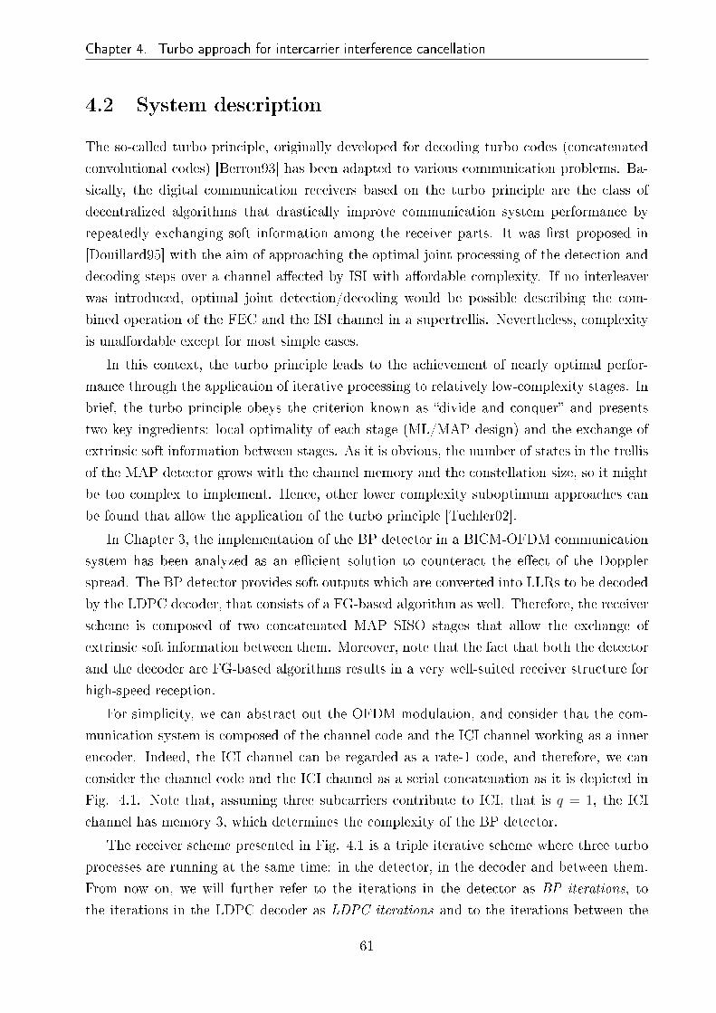
Chapter 4. Turbo approach for intercarrier interference cancellation
4.2 System description
The so-called turbo principle, originally developed for decoding turbo codes (concatenated
convolutional codes) [Berrou93] has been adapted to various communication problems. Ba-
sically, the digital communication receivers based on the turbo principle are the class of
decentralized algorithms that drastically improve communication system performance by
repeatedly exchanging soft information among the receiver parts. It was �rst proposed in
[Douillard95] with the aim of approaching the optimal joint processing of the detection and
decoding steps over a channel a�ected by ISI with a�ordable complexity. If no interleaver
was introduced, optimal joint detection/decoding would be possible describing the com-
bined operation of the FEC and the ISI channel in a supertrellis. Nevertheless, complexity
is una�ordable except for most simple cases.
In this context, the turbo principle leads to the achievement of nearly optimal perfor-
mance through the application of iterative processing to relatively low-complexity stages. In
brief, the turbo principle obeys the criterion known as �divide and conquer� and presents
two key ingredients: local optimality of each stage (ML/MAP design) and the exchange of
extrinsic soft information between stages. As it is obvious, the number of states in the trellis
of the MAP detector grows with the channel memory and the constellation size, so it might
be too complex to implement. Hence, other lower complexity suboptimum approaches can
be found that allow the application of the turbo principle [Tuchler02].
In Chapter 3, the implementation of the BP detector in a BICM-OFDM communication
system has been analyzed as an e�cient solution to counteract the e�ect of the Doppler
spread. The BP detector provides soft outputs which are converted into LLRs to be decoded
by the LDPC decoder, that consists of a FG-based algorithm as well. Therefore, the receiver
scheme is composed of two concatenated MAP SISO stages that allow the exchange of
extrinsic soft information between them. Moreover, note that the fact that both the detector
and the decoder are FG-based algorithms results in a very well-suited receiver structure for
high-speed reception.
For simplicity, we can abstract out the OFDM modulation, and consider that the com-
munication system is composed of the channel code and the ICI channel working as a inner
encoder. Indeed, the ICI channel can be regarded as a rate-1 code, and therefore, we can
consider the channel code and the ICI channel as a serial concatenation as it is depicted in
Fig. 4.1. Note that, assuming three subcarriers contribute to ICI, that is q = 1, the ICI
channel has memory 3, which determines the complexity of the BP detector.
The receiver scheme presented in Fig. 4.1 is a triple iterative scheme where three turbo
processes are running at the same time: in the detector, in the decoder and between them.
From now on, we will further refer to the iterations in the detector as BP iterations, to
the iterations in the LDPC decoder as LDPC iterations and to the iterations between the
61

Chapter 4. Turbo approach for intercarrier interference cancellation
∑
FEC ENCODER INTERLEAVER MAPPER
sn sn+1sn−1
Hn,n Hn,n+1Hn,n−1
AWGN
SISO DECODER SISO DETECTORDEINTERLEAVER
INTERLEAVER
CHANNEL
TURBO RECEIVER
Figure 4.1: Turbo receiver consisting of the concatenation of the detector and the decoder,where the ICI channel works as a rate-1 inner code.
detector and the decoder as turbo iterations. A more detailed description of the model
depicted in Fig. 4.1 is provided in Fig. 4.2 for the receiver side, where LE (cn,m) denotes the
extrinsic LLRs at the output of the detection process which are taken as a priori LLRs in
the decoder (LA (cn,m)) after having been interleaved. LD (cn,m) refers to the extrinsic LLRs
at the output of the decoder which are used to reconstruct symbol likelihoods to be used as
a priori information in the detector.
CP FFTBP
detector
LLRcalculator π−1
LDPCdecoder
πSymbollikelihood
reconstructor
rn yn
P (sn|y)LE (cn,m)
LA (cn,m)
LD (cn,m)P (sn)
Figure 4.2: Block diagram of the BICM iterative receiver chain including the BP detector.
The BP detector computes the marginal a posteriori probabilities P (sn|y) given N re-
ceived symbols applying the SP rule described in (3.7), (3.8) and (3.9). In the initial detection
step, it is assumed that no a priori information is available and hence we have P (sn) = 0.
Note that the output of the detector and the a priori input are independent to each other,
which is the essential feature of any system applying the turbo principle. Hence, the LLR cal-
culator makes use of these marginal a posteriori probabilities to calculate the corresponding
LLRs as follows:
62
Chapter 4. Turbo approach for intercarrier interference cancellation
LE (cn,m) = log
∑∀cn:cn,m=0 P (sn|y)
∏Mj=1 P (cn,j)
∑∀cn:cn,m=1 P (sn|y)
∏Mj=1 P (cn,j)
, (4.1)
assuming M LLRs for each of the N received symbols. The MAP decoder computes the
a posteriori probabilities P (cn,m = κ|L (c1,1) , L (c1,2) , ..., L (cN,M)), κ = {0, 1}, and outputs
the di�erence
LD (cn,m) = lnP (cn,m=1|LA (c1,1) , ..., LA (cN,M))
P (cn,m=0|LA (c1,1) , ..., LA (cN,M))− ln
P (cn,m = 1)
P (cn,m = 0), (4.2)
where the detector output is considered to be a priori information to the decoder. The next
step in the turbo procedure is to feed the detector back considering as a priori information
the extrinsic information at the output of the decoder. For that purpose, taking into account
that the SP rule in the detector is performed in the symbol domain, we have to generate soft
symbols from the LLRs. Basic LLR algebra shows that the bit probabilities are obtained
from the LLRs by evaluating
P (cn,m) =1
1 + exp (−LD (cn,m))exp (−cn,m · LD (cn,m)) . (4.3)
The a priori inputs P (sn) for a given constellation are obtained multiplying all the bit
probabilities corresponding to the symbol P (sn) =∏M
m=1 P (cn,m). Finally these a priori
probabilities are multiplied in each variable node of the detector FG with the rest of incoming
messages as it is depicted in Fig.4.3.
snfk
fk−1
fk+1
µfk+1→sn (sn)
µfk−1→sn (sn)
µfk→sn (sn)
P (sn)
Figure 4.3: Example of a variable node processing a priori information of the correspondingsymbol.
Once we have built the turbo scheme, there are two major questions to be answered:
• Under what circumstances can we guarantee convergence to the ML solution?
• How long will it take to converge?
63

Chapter 4. Turbo approach for intercarrier interference cancellation
Both questions are hard to answer and we can only try to get the optimum solution by
simulation. A turbo schedule has to be de�ned for this purpose, that is, the amount of
iterations to be performed in each of the stages for each of the turbo iteration must be
expected.
The turbo procedure explained so far corresponds to the original one, typically viewed
as two processors running MAP algorithms and exchanging soft decision information. In
this work, we will further refer to this �rst approach as classical approach. There is an
alternative derived from Wiberg's PhD dissertation [Wiberg96] and further advances, which
is commonly described as passing soft decision messages on cyclic graphical models. This
second approach will be further denoted as graphical approach.
4.3 Pilot-assisted factor graph based detection
Many wireless communication systems use training data sequences for channel estimation.
For instance, DVB standards consider di�erent pilot patterns in order to adjust the trans-
mission requirements to di�erent channel conditions. The inclusion of pilot carriers has some
implications in signal detection based on FGs, which have to be taken into account. The
�rst one is that detection has to be performed before pilot removal. This is obvious, since
otherwise the FG representation does not re�ect the symbol correlation caused by the ICI
channel. This fact makes the FG longer since variable and function nodes corresponding
to pilot carriers have to be taken into account. However, at the same time, there is known
information that we can use in order to assist the detection process. This gives rise to the
term pilot-assisted FG-based detection. Fig. 4.4 shows how to deal with pilot carriers in the
message passing process, where sn and fk are the variable and function nodes corresponding
to a given pilot symbol, respectively.
fk fk+1
snsn−1
fk−1
sn+1
Figure 4.4: Pilot processing in the factor graph.
64

Chapter 4. Turbo approach for intercarrier interference cancellation
On one hand, outgoing messages from fk are more accurate representations of marginal
distributions since known information corresponding to sn has been used in (3.7). On the
other hand, messages transmitted by variable node sn are uniform distributions of the corre-
sponding pilot symbol, which are useless for data symbol detection. Thus, we can consider
variable node sn as an idle node and disconnect it from its neighbors. As we can see in
Fig. 4.4, some cycles are straightforwardly removed from the FG as a consequence of discon-
necting variable nodes corresponding to pilot symbols. As an example, considering the PP1
pilot pattern of DVB-T2, where pilot carriers represent the 8% of the total carriers, 8% of
length-4 cycles are directly removed, which yields an additional performance improvement.
Note that the use of clusters of pilot carriers (consecutive pilot carriers), as it is usual for
channel estimation in mobile receivers, would cause the FG to be split into several partitions
with no connection among them. This is not something desirable for the SP algorithm since
it prevents messages from spreading over the FG. In other words, it provokes messages to be
con�ned in a reduced portion of the FG. Of course, the performance degradation due to this
fact depends on the convergence behavior of the algorithm, being negligible if the algorithm
tends to converge fast (in few iterations).
There are other alternatives to deal with pilot carriers in the FG. For example, it is
possible to extend the message-alphabet by including new points in the constellation that
refer to pilot tones. Obviously, this would increase the complexity of the algorithm. In this
work, considering that the BP detector converges relatively fast, we have adopted the former
way of proceeding.
4.4 Classical approach
This is the original turbo receiver approach typically viewed as two processors exchanging
soft decision information as it is represented in Fig. 4.2. Note that, in our receiver design,
this implies resetting all messages in the detector and decoder FGs each time they are
provided with a priori information, so that any memory of the previous iterations is removed.
Therefore, when the detector FG is provided with a priori information, it is considered
that the value of the messages coming from factor nodes is zero, as it is depicted in Fig.
4.5. Thus, the detection process resumes with the variable nodes transmitting messages to
their neighboring factor nodes. The procedure is equivalent in the decoder FG where it is
considered that messages coming from check nodes are zero.
This way of proceeding is interesting when channel estimation is considered into a turbo
scheme which reestimates the channel in each turbo iteration. Note that, in such a receiver
scheme, unless the detector is reset, the factor nodes would propagate new messages com-
puted with the reestimated channel frequency response and these would merge with old
messages from the previous turbo iteration, which had been computed with a di�erent chan-
65

Chapter 4. Turbo approach for intercarrier interference cancellation
snfk
fk−1
fk+1
[0]
P (sn)
[0]
[0]
Figure 4.5: Example of a variable node processing a priori information of the correspondingsymbol in the classical turbo approach.
nel frequency response. This fact could cause the SP algorithm to become unstable and
therefore degrade the detector performance.
4.4.1 EXIT chart analysis
Two very well-known tools can be used to analyze the convergence behavior of a turbo pro-
cess at cli� region: the EXIT charts introduced by Stephan ten Brink [tenBrink01] and the
so-called density evolution [Richardson01]. The former visualize the exchange of extrinsic
information between the constituent decoders, while the latter analyzes the decoding behav-
ior by tracking the densities of the messages throughout the iterations, being mainly used
for the analysis and optimization of LDPC codes. Calculating and tracking the densities
can be di�cult, specially, if more complicated component codes are used like the ones in our
receiver design. Note that we are analyzing a serially concatenated scheme over an AWGN
channel with the LDPC as the outer constituent decoder and the BP detector as the inner
constituent decoder. Assuming that the bit interleaver is su�ciently large, the EXIT charts
provide an accurate prediction of the convergence behavior. Due to the complexity of the
system, EXIT functions have to be assessed by Montecarlo simulation.
The EXIT chart characterizes the relation between input and output LLRs of the com-
ponent decoders in terms of mutual information. To measure the information contents of
the a priori knowledge, Shannon's mutual information I = I (S;L) between the transmit-
ted bits S and the LLR values L is used. For simplicity, let us assume binary phase-shift
keying (BPSK) modulation and a large interleaver, which assures statistical independence
and Gaussian distribution for the input L with parameter σ2 ↔ I (L;S). As it is depicted
in Fig. 4.6, we vary the quality of the a priori information and observe the extrinsic output
information. LA denotes the a priori input LLR and LE refers to the extrinsic output LLR.
66

Chapter 4. Turbo approach for intercarrier interference cancellation
IAdet (S;LAdet)
INNER DECODER OUTER DECODER
IEdec (S;LEdec)
IEdet (S;LEdet) IAdec (S;LAdec)
Figure 4.6: Modeling a serial concatenated system with EXIT functions.
Considering S and Y to be two real valued random variables, the Shannon's mutual
information is de�ned as
I (S;Y ) =
∫ ∫f (s, y) log
f (s, y)
f (s) f (y)dsdy, (4.4)
If we restrict ourselves to BPSK, s ∈ {+1,−1}, and equally likely inputs s, the mutual
information becomes
I (S;Y ) =1
2
∑
s=+1,−1
∫ ∞
−∞f (y|s) log
f (y|s)f (y)
dy. (4.5)
The integral in 4.5 has to be evaluated numerically. Applying additional assumptions
on the distributions p (y|s), such as considering they are symmetric and consistent, we can
compute the mutual information as time a average and avoid numerical integration. Due
to suboptimal detectors, often distributions are not exactly consistent. However, it turns
out that we can mostly assume consistency and still obtain accurate results. On the other
hand, because of the nonlinearity of the decoder, the L-value distribution of the output is in
general unknown and no longer Gaussian. Nevertheless, by invoking the ergodicity theorem,
we can measure the mutual information from a large number N of samples even for non-
Gaussian or unknown distributions. Combining these constraints with 4.5 and invoking the
ergodicity theorem leads to estimating the mutual information only from the magnitudes
without knowing the correct data [tenBrink01] as
I (L;S) = 1− E {log2 (1 + exp (−L))} ≈ 1− 1
N
N∑
n=1
log2 (1 + exp (−snLn)) . (4.6)
4.4.1.1 Numerical results
Simulation parameters in this chapter are the same as in Chapter 3, except that we incorpo-
rate the RA6 channel model and the 16QAM modulation, which is simulated in combination
with CR=1/2. The PP1 DVB-T2 [ETSI09] pilot pattern has been adopted. We consider
ideal CSI as well as perfect synchronization throughout this chapter. From extensive simu-
67

Chapter 4. Turbo approach for intercarrier interference cancellation
lation results, we know that the best BER result is achieved with the next turbo schedule:
2 BP iterations and 20 LDPC iterations in each turbo iteration.
Fig. 4.7a and 4.7b depict the EXIT functions for both QPSK and 16QAM modulations.
Fig. 4.7a shows the behavior of detector EXIT function in the ICI-free case and when a high
Doppler frequency is considered. We notice that when the Doppler frequency is zero the
curve is �at, and that the Doppler frequency provides a slight slope. The absence of Doppler
frequency equals removing the inner encoder from the system, so that the only purpose of the
BP detector is to carried out the MAP detection. In other words, the system equals a BICM
communication system with iterative MAP demapping. As is it well-known, when Gray
mapping is used (as it is the case), the detector EXIT function is �at, so that performing
the turbo principle between the decoder and the demapper is useless [Schreckenbach03].
However, the detector EXIT function becomes steeper as the Doppler frequency increases.
0 0.1 0.2 0.3 0.4 0.5 0.6 0.7 0.8 0.9 10
0.1
0.2
0.3
0.4
0.5
0.6
0.7
0.8
0.9
1
IAdet, IEdec
IEde
t, IA
dec
fd=0
fd=0.5
0 0.1 0.2 0.3 0.4 0.5 0.6 0.7 0.8 0.9 10
0.1
0.2
0.3
0.4
0.5
0.6
0.7
0.8
0.9
1
IAdet, IEdec
IEde
t, IA
dec
Gray mappingMSEW mappingLDPC decoder CR=1/2
(a) (b)
Figure 4.7: Detector EXIT function for QPSK modulation (a) and detector and decoderEXIT functions for 16QAM modulation with di�erent mapping schemes when fd = 0.22 (b).TU6 channel has been considered in both cases.
Fig. 4.7b shows detector and decoder EXIT functions for the 16QAM modulation. Two
mapping labels have been assessed: Gray and maximum squared euclidian weight (MSEW).
It is shown that for fd = 0.22, the detector function is almost �at when Gray mapping
is considered. Again, the Gray mapping does not give any gain when the a priori mutual
information is increased and iterations do not give any bene�ts. For the MSEW label, the
function starts at a lower value and ends up almost in the (1,1) point. However, detector and
decoder functions cross each other preventing from any gain in the iterative process. From
Fig. 4.7, we conclude that when LDPC codes are adopted the best mapping is Gray and in
such case the performance gain provided by the turbo scheme is higher for higher Doppler
frequencies.
Fig. 4.8a shows the EXIT chart for QPSK modulation and fd = 0.5. The system is
68

Chapter 4. Turbo approach for intercarrier interference cancellation
performing in the turbo-cli� region (SNR=8 dB). As it can be seen, the slight slope of the
detector function allows to gain performance in three turbo iterations. Fig. 4.8b shows the
corresponding BER performance versus LDPC iterations, where it is shown that the LDPC
decoder provides free-error output at the fourth turbo iteration. Although the EXIT chart
model is no exact, it provides a reliable reference in order to design the turbo schedule.
0 0.1 0.2 0.3 0.4 0.5 0.6 0.7 0.8 0.9 10
0.1
0.2
0.3
0.4
0.5
0.6
0.7
0.8
0.9
1
IAdet, IEdec
IEde
t, IA
dec
2 4 6 8 10 12 14 16 18 2010
−7
10−6
10−5
10−4
10−3
10−2
10−1
LDPC iterations
BE
R
Turbo iteration 1Turbo iteration 2Turbo iteration 3Turbo iteration 4
(a) (b)
Figure 4.8: EXIT chart (a) and BER vs LDPC iterations (b). QPSK modulation, TU6channel, fd = 0.5 and SNR = 8 dB has been considered.
As a conclusion, based on the EXIT chart analysis, it can be stated that the turbo scheme
operating at high Doppler frequencies converges at few iterations, no more than �ve.
4.5 Graphical approach
The second turbo approach, referred to as graphical approach, was introduced in [Wiberg96]
and is commonly described as passing soft decision messages on cyclic graphical models.
Considering that LDPC codes are decoded using BP algorithms, a joint data detection and
decoding process can be carried out by a higher-order FG as it is depicted in Fig. 4.9. Note
that the EXIT charts cannot be used to analyze the convergence behavior of this approach
as in the previous section, since detection and decoding are not independent anymore. That
is, detector and decoder FGs are not reset, but they keep memory from previous turbo
iterations.
We now compare the classical and graphical approaches with the non-turbo case as it
was conceived in Chapter 3. The selected turbo schedule is the following for each case:
2 BP iterations and 20 LDPC iterations have been carried out in each turbo iteration in
both turbo approaches, and 3 BP iterations and 50 LDPC iterations are performed in the
non-turbo case.
69

Chapter 4. Turbo approach for intercarrier interference cancellation
f3f2f1 f4 fnf5
s5 sns4s1 s2 s3
LLR calculation Symbol likelihood reconstruction
M
ππ−1
BP
det
ecto
r
factor nodes
variable nodes
variable nodes
check nodesLD
PC
dec
oder
edges defined byparity check matrix
BP
iter
atio
ns
LD
PC
iter
atio
ns
Turb
oit
erat
ions
Figure 4.9: High order FG performing joint data detection and decoding following the graph-ical approach for turbo reeption.
Fig. 4.10 shows BER versus SNR performance for TU6 and RA6 channels. As it can
be seen, the graphical approach outperforms the classical one in both cases, providing a
performance gain of about 0.8 dB at BER= 10−4. On the other hand, there is a slight
di�erence between the non-turbo case and the classical turbo approach for the turbo schedule
adopted here.
4.5 5 5.5 6 6.5 7 7.5 8 8.5 910
−4
10−3
10−2
10−1
100
SNR (dB)
BE
R
Non−turboClassical turbo approachGraphical turbo approach
3 4 5 6 7 8 910
−4
10−3
10−2
10−1
100
SNR (dB)
BE
R
Non−turboClassical turbo approachGraphical turbo approach
(a) (b)
Figure 4.10: Performance comparison of non-turbo reception, classical turbo approach and
the graphical turbo approach for TU6 (a) and RA6 (b) channels. fd = 0.5 has been consid-
ered.
70

Chapter 4. Turbo approach for intercarrier interference cancellation
The performance gain introduced by the turbo iterations is shown in Fig. 4.11, where
BER curves are depicted for the �ve turbo iterations when TU6 channel is considered. As
it can be seen, the performance gain between the �rst and the �fth iteration is more than 1
dB at BER= 10−4. Besides, it is noteworthy that the graphical approach outperforms the
non-turbo case at the second iteration, which means that better BER result is achieved with
less amount of total iterations (BP iterations + LDPC iterations).
6 6.2 6.4 6.6 6.8 7 7.2 7.4 7.6 7.8 810
−4
10−3
10−2
10−1
100
SNR (dB)
BE
R
Turbo iteration 1Turbo iteration 2Turbo iteration 3Turbo iteration 4Turbo iteration 5
Figure 4.11: BER vs SNR performance of the graphical approach for the �ve turbo iterations.
Fig. 4.12 shows the graphical approach performance for QPSK. From Fig. 4.12a, we
can see that the BER performance is better than the ICI-free case up to fd = 0.3. This
can be explained by the fact that the proposed BP exploits the available frequency-diversity,
improving the diversity order with respect to the standard BICM-OFDM system. On the
other hand, note that the BER curve shifts to the right side as the Doppler frequency
increases. This is mostly caused by the residual ICI due to not considering more subcarriers
contributing to ICI, which would enhance the BER performance at the cost of much higher
complexity. The BER behavior is quite di�erent over the RA6 channel (Fig. 4.12b). It can
be seen that the performance for fd = 0.3 is substantially better than for fd = 0.1. The
reason behind this apparently strange behavior is that wireless channels with short delay
spread can largely degrade the BER performance of a BICM-OFDM systems due to the
high correlation between contiguous subcarriers. In [May04] it is shown that the maximum
diversity order that a BICM-OFDM system can achieve is min (dfree, L), where dfree refers
to the Hamming distance of the channel code and L stands for the number of channel taps.
Note from Fig. 4.12 that the BER performance of the ICI-free case is much worse over the
RA6 channel. Therefore, the diversity order gain due to the inclusion of the BP detector is
more evident in the RA6 channel case.
71

Chapter 4. Turbo approach for intercarrier interference cancellation
3 3.5 4 4.5 5 5.5 6 6.5 7 7.510
−4
10−3
10−2
10−1
100
SNR (dB)
BE
R
ICI−freefd=0.1
fd=0.3
fd=0.5
3 4 5 6 7 8 9 10 1110
−4
10−3
10−2
10−1
100
SNR (dB)
BE
R
ICI−freefd=0.1
fd=0.3
fd=0.5
(a) (b)
Figure 4.12: Graphical turbo approach performance for di�erent Doppler frequencies over
TU6 channel (a) and RA6 channel (b) when QPSK modulation is considered.
Last, we provide BER versus SNR results for 16QAM in order to assess the proposed
receiver design with a higher constellation order. In this case, the mentioned residual ICI,
which can be modeled as a near-Gaussian noise, a�ects much more to the signal, preventing
from achieving the free-ICI case at the Doppler frequencies considered for the QPSK modu-
lation. Fig. 4.13 shows that the BP detector is able to remove the error-�oor caused by the
Doppler spread at fd = 0.22 over both channel models considered here. BER results over
TU6 channel indicate that there is a performance loss of about 1.2 dB at BER= 10−4 with
respect to the ICI-free case. Regarding the RA6 channel, it is shown that the BP detector
achieves ICI-free performance at such Doppler frequency.
0 2 4 6 8 10 1210
−4
10−3
10−2
10−1
100
SNR (dB)
BE
R
ICI−freefd=0.22
one−tap equalization
4 5 6 7 8 9 10 11 1210
−4
10−3
10−2
10−1
100
SNR (dB)
BE
R
ICI−freefd=0.22
one−tap equalization
(a) (b)
Figure 4.13: Graphical turbo approach performance for di�erent Doppler frequencies over
TU6 channel (a) and RA6 channel (b) when 16QAM modulation is considered.
72
Chapter 4. Turbo approach for intercarrier interference cancellation
4.6 Chapter Summary
This chapter analyzes the performance of the proposed BP detector as part of a turbo receiver
design along with the LDPC decoder, where extrinsic soft information is exchanged between
the decoder and the detector. The fact that both detection and decoding are performed by
BP algorithms allows high speed joint detection and decoding.
Section 4.2 describes the turbo receiver scheme, where the ICI channel works as an inner
encoder concatenated with the LDPC as the outer constituent code. Section 4.3 describes
how to deal with pilots in the FG and which are the bene�ts and drawbacks of the presence
of pilots in the detection process are described. Section 4.4 presents the classical turbo
approach, according to which soft decision information is exchanged between independent
processes. The convergence behavior of the classical approach is analyzed using EXIT charts.
The classical approach is compared to the generalized view of the graphical approach and the
non-turbo case in Section 4.5. Extensive numerical results are provided considering QPSK
and 16QAM modulation, as well as TU6 and RA6 channel models. It is shown that the
proposed receiver scheme provides excellent performance at high mobility scenarios
73
Chapter 5
Impact of BP-based ICI cancellation in
mobile DVB-T2
5.1 Introduction
Second generation DVB speci�cations have provided increased robustness and spectral e�-
ciency yielding the fully incorporation of multimedia broadcasting and high de�nition (HD)
television to the terrestrial mean. Predictably, terrestrial (DVB-T2) and handheld (DVB-
NGH) versions will be the two leading standards for terrestrial broadcasting all over the
world. Mobility support is one of the key features of the advent of the second generation
DVB systems, which try to deal with the challenge of enabling mobile broadband services
at high vehicular speed. Although initially DVB-T2 was designed for �xed receivers, it is
supposed to allow mobile reception with the same spectrum characteristics as DVB-T, since
the combination of LDPC codes, as part of the FEC strategy, and time interleaving makes
this standard very robust against signal distortion due to the time variation of the channel.
The DVB-T2 speci�cation allows for the possibility of maximizing the performance in
SFN applications. Compared with DVB-T standard, longer OFDM blocks have been added
(e.g. 32K) to improve the performance of SFNs and increase the symbol period. This
increase in the symbol period, in turn, allows for a reduction in the proportional size of the
GI while still handling multipath re�ections. In fact, new standards appearing in recent years
propose very long OFDM blocks with the aim of increasing spectral e�ciency or enhance
the robustness in SFNs. However, long blocks are more vulnerable to time variations of the
channel, which in high mobility scenarios destroy orthogonality among subcarriers, resulting
in ICI. The use of long OFDM blocks represents a challenging technical problem when it is
combined with mobile signal reception.
In this chapter, the DVB-T2 speci�cation is taken as a reference for DVB technology, and
the proposed BP detector is assessed over its physical layer. Along with ideal CSI, channel
estimation is also considered in order to analyze its impact on the BP detection process in
a realistic receiver.
74

Chapter 5. Impact of BP-based ICI cancellation in mobile DVB-T2
5.2 DVB-T2 to pave the way of DVB-NGH
Since the introduction of DVB-H, signi�cant changes have taken place in the delivery and
consumption of multimedia content. On one hand, the multimedia content market is going
through a big change towards a range of rich multimedia tra�c (various video and audio
contents, images and text messages). On the other hand, there is another signi�cant recent
change: the convergence of the �xed and mobile paradigms. With the introduction of DVB-
T2, there is a need to look at ways of leveraging its advantages in developing NGH. Radio
spectrum is a scarce resource and its use by di�erent networks without interfering with
each other is essential. Therefore, spectrum sharing of future broadcasting and cellular
networks and e�ective utilization of this resource in delivering services via di�erent networks
is essential for next generation systems.
Considering the above, the aim of this thesis dissertation is to take the current terrestrial
TV standards a step forward providing improvements in two directions: increase the spectral
e�ciency and enhance the robustness. Fig. 5.1 depicts the trade-o� between the spectral
e�ciency and robustness in mobile terrestrial DTV.
SDTV/HDTV
64/256QAM
FIXED
DVB-T
DVB-T2
SDTV
16QAM
PORTABLE
DIGITAL TV MOBILE TV
DVB-H DVB-SH
DVB-T2 DVB-NGH
LDTV
QPSK
MOBILE
BITRATEROBUSTNESS
LITE
Figure 5.1: Bitrate vs robustness trade-o�.
At this point, it is of interest to analyze the commercial and technical requirements
de�ned for the development of the upcoming DVB-NGH speci�cation. We enumerate the
most signi�cant ones:
• Wide coverage: a user access services across an entire territory. The implication is that
networks aimed at wide area coverage must be e�cient and a�ordable to build.
• Robust reception: it must be possible to access services for either indoor or outdoor,
and stationary, walking or traveling at speed.
75

Chapter 5. Impact of BP-based ICI cancellation in mobile DVB-T2
• Responsive: it must be quick to start up and to access audio-visual and interactive
services, fast channel change times.
• Extremely fast moving usage scenarios: mobile vehicular reception is considered at
speeds from 15 to 350 km/h.
• Low system end-to-end delay: important for live events; e.g. use of the NGH system
during sports events.
• Extended battery life: it must be able to o�er extended viewing sessions.
• Quality improvement: it is likely that in the medium term the terminals will have
larger screens (e.g., smartphones, tablets, etc.).
• Capacity improvement: recognizing that capacity can be traded for robustness, the
overall capacity improvement, shall be at least 50% compared to DVB-H for a given
robustness.
5.2.1 The bene�ts of employing long OFDM blocks in terrestrial
broadcasting systems
Considering the technical and commercial requirements imposed to future mobile terrestrial
DTV speci�cations, the use of long OFDM blocks presents a bunch of interesting advan-
tages. In fact, there is a growing trend toward employing long OFDM blocks in terrestrial
broadcasting systems. On one hand, it allows to provide wider coverage using SFNs. A
document from Mobile Multi-Meda (M3) [Gallard11], a French collaborative project, shows
why DVB-NGH is better than the LTE/3GPP E-MBMS (�Evolved Multimedia Broadcast
Multicast Services�) in terms of spectrum e�ciency and reuse of existing broadcast antennas.
DVB-NGH can include much larger GIs, allowing a maximum cell radius of up to 107 km,
suitable for a high power, high antenna transmitter site and multiple low/medium power
transmitters in a SFN, leading to e�cient and a�ordable network design.
Secondly, the use of long OFDM blocks leads to maximizing the net throughput, ful�lling
the technical requirement by which means overheads such as packet headers should be mini-
mized, without losing functionality. Last, but not least, taking into account that 32K-length
symbols are already being used for �x terrestrial DTV (e.g., UK), the same symbol length
could be used for mobile reception with di�erent PLPs that could enable service speci�c
robustness without occupying other frequency bands.
Of course, a trade-o� among e�ciency, SFN performance and mobile robustness must
be obtained. Using long OFDM blocks leads to increasing the robustness in SFNs and
the net throughput, but has at least two counterparts at the same time: the e�ect of the
Doppler frequency is much higher, which restricts the use of high constellation orders and
76

Chapter 5. Impact of BP-based ICI cancellation in mobile DVB-T2
it can provoke high latencies if the receiver design is not properly constrained. Therefore,
advanced signal processing techniques have to be considered in order to counteract the severe
e�ect of the Doppler frequency keeping latency and complexity at reasonable levels.
System performance of �rst generation DVB systems in mobile scenarios has been widely
addressed by previous literature [Poggioni09, Herlekar05, Lu08, Wilhelmsson07]. At the
same time, many di�erent schemes have been proposed for signal reception with possible ap-
plication to DVB systems [Tomasin05, Hwang09]. However, for the best of our knowledge,
little has been done regarding the second generation DVB standards [Ochandiano10]. Re-
cently, a time-domain per sub-block equalizer has been presented [Baracca11] which tackles
the same problem formulated in this work. The main drawbacks of this proposal are its
limited performance and the impossibility of employing pilot tones for channel estimation.
5.3 DVB-T2 performance in mobile scenarios
We highlight two features of the DVB-T2 physical layer due to their importance when com-
bating the signal distortion caused by ICI: LDPC codes as part of the FEC scheme, and
the time interleaver. It is well-known that when the codeword is su�ciently large, ICI can
be modeled as an additive Gaussian random noise [Wang06], which can be e�ectively coun-
teracted by the LDPC code at low and moderate Doppler frequencies. On the other hand,
the primary objective of the time interleaver is to provide time-domain diversity when used
along with powerful error correction coding. As it is usual, the maximum time interleaver
span is restricted by the standard in order to limit the receiver latency.
Fig. 5.2 shows the simpli�ed block diagram of the conventional DVB-T2 receiver. In
this research work, assuming the �rst option for time interleaving de�ned in the DVB-T2
standard, we consider that each interleaving frame contains one TI-block and is mapped
directly to one T2-frame [ETSI09].
OFDM−1equalization
one-tap Timedeinterleaver
Bitdeinterleaver decoder
LDPC
estimatorChannel
Figure 5.2: Simpli�ed block diagram of the conventional DVB-T2 receiver (CONV).
The DVB-T2 implementation guidelines document [DVB09] proposes several channel
models, from which two have been chosen to analyze the performance of the proposed detec-
tion techniques in mobile conditions: COST 207 TU6 and RA6 channels [COST20789]. We
77

Chapter 5. Impact of BP-based ICI cancellation in mobile DVB-T2
consider maximum normalized Doppler frequency fd = 0.5. Table 5.1 describes the simula-
tion parameters adopted throughout this work. Under such conditions, fd = 0.5 corresponds
to about 200 km/h of vehicular speed. The BER is computed after at the output of the
LDPC decoder.
Table 5.1: Simulation parameters in Chapter 5.
Parameter Value
Carrier frequency 760 MHz
Bandwidth 8 MHz
Number of subcarriers (N) 32784
Subcarrier spacing 280 Hz
Length of one OFDM block (Tu) 3584µs
Length of the guard interval (Tu/4) 896µs
Modulation QPSK, 16QAM
FEC length (LDPC) 64800 bits
Code rate 2/3 (QPSK), 1/2 (16QAM)
Channel model RA6, TU6
As it is shown in Fig. 5.3, the time interleaver, in conjunction with LDPC codes, makes
DVB-T2 very robust in a wide range of mobile communication scenarios. Mobile reception
of DVB-T2 is assessed according to the number of FEC blocks considered in the TI-block.
Note that for the time interleaving con�guration and transmission parameters adopted in
this paper, the maximum number of FEC blocks in the TI-block is limited to 17 by the
standard [ETSI09].
According to Fig. 5.3a, error-free reception is possible for the RA6 channel up to fd = 0.3
when QPSK modulation is considered without the inclusion of any speci�c signal processing
technique for ICI suppression. However, beyond this Doppler frequency, the performance
crashes giving rise to a high error �oor. The BER curves for TU6 channel follow similar
trends. In this case, the maximum Doppler frequency for error-free communication is even
lower.
Fig. 5.3b shows the same performance results for 16QAM modulation. As it is known,
the distortion caused by ICI becomes severer as the modulation order increases. Therefore,
the maximum Doppler frequency that allows error-free communication is lower in 16QAM
than in QPSK. It can be seen that error-free communication is possible over RA6 channel
for fd = 0.23 when 19 FEC blocks are used in the TI-block. As in the QPSK case, the
maximum Doppler frequency for error-free communication is lower for TU6 channel.
From this analysis, it is concluded that the physical layer of DVB-T2 allows good mobile
signal reception in a wide variety of mobile environments. However, for the channels of
78

Chapter 5. Impact of BP-based ICI cancellation in mobile DVB-T2
1 5 10 20 30 5010
−8
10−7
10−6
10−5
10−4
10−3
10−2
10−1
100
Number of FEC blocks in the TI block
BE
R
fd=0.3 TU6
fd=0.3 RA6
fd=0.4 TU6
fd=0.4 RA6
fd=0.5 TU6
fd=0.5 RA6
1 5 10 20 30 5010
−8
10−7
10−6
10−5
10−4
10−3
10−2
10−1
100
Time Interleaving depth (FEC)
BE
R
fd=0.3 TU6
fd=0.3 RA6
fd=0.25 TU6
fd=0.25 RA6
fd=0.23 TU6
fd=0.23 RA6
(a) (b)
Figure 5.3: DVB-T2 performance versus di�erent number of FEC blocks in the TI-block(time interleaving depth) at high SNR regime (SNR=30dB) for QPSK (a) and 16QAM (b).
interest in this research work, it is not able to provide free-error communication by itself.
Therefore, advanced signal detection strategies need to be included for that purpose at the
expense of increasing the complexity of the receiver.
5.4 Belief propagation detection over DVB-T2
Two things have to be taken into account to design detection strategies for DVB standards:
�rst, the use of long OFDM blocks forces to adopt parallel structures in order to ful�ll
stringent latency requirements, and second, since LDPC codes are decoded by means of
SISO decoders, soft values are required at the output of the detector. BP algorithm �ts both
requirements and therefore suits very well to second generation terrestrial DVB standards.
Two reception schemes are here proposed, both based on the traditional DVB-T2 phys-
ical layer. The �rst proposed scheme (PS1) substitutes the MAP one-tap equalizer in the
conventional DVB-T2 receiver (CONV) by the BP detector, and maintains the time inter-
leaver. In the second proposed scheme (PS2), the time interleaver is subtracted out and the
turbo approach is applied exchanging soft information between the decoder, the detector
and the channel estimator. The aim of both proposed schemes is to achieve a reasonable
trade-o� among performance, complexity and latency. The last gains in importance when
real-time multimedia tra�c requires stringent end-to-end delays. The combination of the
turbo approach and the inclusion of the time interleaver would cause excessive time-delays
in signal reception, and it is therefore discarded.
The mechanism behind the proposed schemes combating ICI is the exploitation of the
frequency and time-diversity provided by the time-varying channel. PS1 makes use of
79

Chapter 5. Impact of BP-based ICI cancellation in mobile DVB-T2
both frequency-diversity (frequency correlation in the received signal due to ICI) and time-
diversity (due to the use of time interleaver along with error correction coding in a time-
varying channel) to provide free-error reception (see Fig. 5.4). In PS2, the lack of the time
interleaver is replaced by the performance gain o�ered by the turbo approach (see Fig. 5.7).
Note that in the PS2 scheme, the whole reception process, except channel estimation, can
be understood in terms of a high-order FG including joint signal detection and decoding,
where soft decision messages are exchanged on a cyclic graphical model. Optional signal
processing stages included in the standard (e.g., constellation rotation) are not considered
in this research work.
5.4.1 First proposed reception scheme (PS1)
A simpli�ed block diagram of PS1 reception scheme is shown in Fig. 5.4, where the one-
tap MAP equalizer has been replaced by the BP detector. Based on the simulation results
analyzed in Chapter 3, three iterations have been carried out in the BP detector and 50
iterations in the LDPC decoder.
OFDM−1detectorBP Time
deinterleaverBit
deinterleaver decoderLDPC
estimatorChannel
Figure 5.4: Simpli�ed block diagram of the �rst proposed scheme (PS1).
5.4.1.1 Performance with ideal CSI
Fig. 5.5 shows the BER performance of PS1 for TU6 channel. As it was mentioned, this
scheme pro�ts from both frequency-diversity (BP detector) and time-diversity (time inter-
leaver). In Fig. 5.5a BER results are depicted for the three iterations carried out in the
detector considering 10 FEC blocks per TI-block. As it can be seen, the second iteration is
able to remove the error �oor caused by the Doppler spread, and the third iteration gives
a tight performance gain of about 0.3 dB at BER= 10−4, approaching the ICI-free curve
up to 1 dB. This corroborates the e�ciency of the proposed BP detector in such channel
conditions.
In turn, time interleaving performance is assessed in Fig. 5.5b by keeping the number
of BP iterations �xed and varying time interleaving depths (1, 5 and 10 FEC blocks per
TI-block). As it is shown, the maximum performance gain that time interleaving can o�er is
80

Chapter 5. Impact of BP-based ICI cancellation in mobile DVB-T2
5 5.5 6 6.5 7 7.5 8 8.5 9 9.5 1010
−4
10−3
10−2
10−1
100
SNR (dB)
BE
R
CONV ICI−free, Ideal CSIPS1, 3 BP iterations, 10FEC, Ideal CSIPS1, 2 BP iterations, 10 FEC, Ideal CSIPS1, 3 BP iterations, 10 FEC, BEM channel estimationPS1, 1 BP iteration, 10 FEC, Ideal CSICONV, Ideal CSI
5 5.5 6 6.5 7 7.5 810
−4
10−3
10−2
10−1
100
SNR (dB)
BE
R
PS1, 3 BP iterations, 10 FEC, Ideal CSIPS1, 3 BP iterations, 5 FEC, Ideal CSIPS1, 3 BP iterations, 1 FEC, Ideal CSI
(a) (b)
Figure 5.5: PS1 BER performance comparison for di�erent number of BP iterations, withfd = 0.5 over TU6 channel, considering ideal and partial CSI. 10 FEC blocks per TI-blockare assumed (a). PS1 BER performance for di�erent number of FEC blocks per TI-block,with fd = 0.5 over TU6 channel, considering 3 BP iterations (b).
around 0.5 dB. Consequently, for the TU6 channel model, the frequency-diversity exploita-
tion o�ered by the BP detector is much more e�cient than the e�ects of the time-diversity
provided by the time interleaver.
Fig. 5.6a and 5.6b show the analogue analysis for RA6 channel model. As it is well-
known, the BER behavior of a BICM-OFDM scheme is substantially worse in less selective
channels. Therefore, it is interesting to extend the simulation results of Fig. 5.5a and5.5b
to the RA6 channel model. The high correlation in the frequency domain due to the short
delay spread of the channel can largely degrade the BER performance, that is, the lower
delay spread leads to frequency-diversity loss. Therefore, as it is shown in Fig. 5.6a, PS1
scheme produces a remarkable impact on the BER, giving a performance gain of about 4 dB
with respect to the ICI-free case at BER= 10−4.
On the other hand, comparing Fig. 5.5b and 5.6b, we can observe that the contribution
of the time interleaver is higher in RA6 than in TU6. The reason behind this behavior is
that spreading out symbols by means of the time interleaver emulates an ergodic channel
[Poggioni09], o�ering a high diversity order gain with respect to the RA6 channel. Besides,
it is worth noting that there is no performance gain beyond 5 FEC blocks per TI-block.
5.4.1.2 Performance with channel estimation
Non-ideal CSI is considered in order to analyze how the detector performs in a realistic
receiver. Channel estimation based on basic expansion model (BEM) is considered [Tang07],
which consists of one of the most promising channel estimation techniques to be applied
81

Chapter 5. Impact of BP-based ICI cancellation in mobile DVB-T2
5 6 7 8 9 10 1110
−4
10−3
10−2
10−1
100
SNR (dB)
BE
R
CONV ICI−free, Ideal CSIPS1, 3 BP iterations, 10 FEC, Ideal CSIPS1, 2 BP iterations, 10 FEC, Ideal CSIPS1, 1 BP iterations, 10 FEC, Ideal CSIPS1, 3 BP iterations, 10 FEC, BEM channel estimationCONV, Ideal CSI
5 5.5 6 6.5 7 7.5 8 8.5 910
−4
10−3
10−2
10−1
100
SNR (dB)
BE
R
PS1, 3 BP iterations, 10 FEC, Ideal CSIPS1, 3 BP iterations, 5 FEC, Ideal CSIPS1, 3 BP iterations, 1 FEC, Ideal CSI
(a) (b)
Figure 5.6: PS1 BER performance comparison for di�erent numbers of BP iterations, withfd = 0.5 over RA6 channel, considering ideal and partial CSI. 10 FEC blocks per TI-blockare assumed (a). PS1 BER performance for di�erent number of FEC blocks per TI-block,with fd = 0.5 over RA6 channel, considering 3 BP iterations (b).
to OFDM communication systems operating in rapidly time-varying channels. Channel
estimation is out of the scope of this thesis, so that the aim of including channel estimation is
not analyzing a given channel estimation technique itself, but assessing how the BP detector
behaves in such conditions in comparison with ideal CSI.
When the channel is assumed to be time-varying, suitable techniques are needed to
estimate the complete channel parameters, including the ICI terms. The channel can be
approximated as
hl = B · hu,l, (5.1)
where hl = [h0,mod(0+l,N), · · · , hN−1,mod(N−1,N)]T , is an N×1 vector that contains the channel
coe�cients for the l-th channel tap from time indexes 0 to N -1. This way, instead of
estimating all the channel coe�cients N ×L, we only need to estimate the BEM coe�cients
hu,l = [h0,l, · · · , hQ,l]T , resulting in a signi�cant reduction of the number of parameters to be
estimated, which are equal to (Q + 1)× L for each OFDM symbol and Q is the amount of
diagonals in the frequency response channel considered to describe the ICI excluding the main
diagonal. B = [b0, · · · ,bQ] is an N × (Q+ 1) matrix that contains Q+ 1 basis functions bqas columns, where bq = [bq,0, · · · , bq,N−1]T whose coe�cients are obtained following [Tang07].
Stacking all the channel taps, hu = [h0,0, · · · , h0,L−1, · · · , hQ,0, · · · , hQ,L−1], yields
H = (B⊗ IL)hu. (5.2)
In order to adapt the previous channel estimation scheme to DVB-T2, pilots have to be
82

Chapter 5. Impact of BP-based ICI cancellation in mobile DVB-T2
clustered in C groups of Lp pilots each. Inside each cluster s(p)c , c = 0, 1, · · · , C − 1, the
frequency-domain Kronecker delta (FDKD) scheme has been adopted, where a nonzero pilot
is placed in the middle, with zero guard bands on both sides [Kannu05]. Stacking all the
pilot clusters together into a pilot vector yields s(p) =[s
(p)T0 , · · · , s(p)T
C−1
]T. A performance
improvement can be seen with larger cluster lengths for high normalized Doppler frequencies
at the expense of higher complexity. Note from Fig. 5.7 that, in PS2 scheme, the channel
estimation can be improved making use of the soft data from the channel decoder as it is
proposed in [Fang10], where not only the pilot carriers are used to estimate the channel,
but also the soft data estimates from detected data symbols. Simulation parameters related
with channel estimation adopted in this work are further explained in [Ochandiano12a].
Taking a look at the BER curves with channel estimation in Fig. 5.5 and 5.6, we notice
that the performance loss due to non-ideal CSI depends on the channel model: following
the track of a highly-selective channel is harder than of a less-selective one. Therefore, the
performance loss in RA6 with respect to the ideal CSI is less than 0.3 dB at BER= 10−4,
whereas TU6 leads to a performance loss of about 1.5 dB at BER=10−4. We conclude that
the estimation error does not cause destructive e�ects to the BP algorithm and it behaves
as an additional noise source leading to the displacement of the BER curve to the right side.
5.4.2 Second proposed reception scheme (PS2)
A simpli�ed block diagram of PS2 reception scheme is shown in Fig. 5.7, where the time
interleaver has been subtracted out and the turbo approach has been included, exchanging
soft information between the LDPC decoder, the detector and the channel estimator. Based
on the simulation results in Chapter 4, 2 iterations have been carried out within the BP
detector and 20 iterations within the LDPC decoder for each of the 5 turbo iterations.
OFDM−1detectorBP Bit
deinterleaver decoderLDPC
estimatorChannel Bit
interleavermapperSoft
LLR updatingpriors computation
Figure 5.7: Simpli�ed block diagram of the second proposed scheme (PS2).
83

Chapter 5. Impact of BP-based ICI cancellation in mobile DVB-T2
5.4.2.1 Performance with ideal CSI
Fig. 5.8a and 5.8b show BER results for PS2 reception scheme over TU6 and RA6, respec-
tively. Note that comparing Fig. 5.8a and 5.5a, PS1 outperforms PS2 up to 0.5 dB over TU6
channel. In the same way, an analogue behavior can be seen over RA6, where PS1 presents a
gain of 1.2 dB with respect to PS2. Therefore, PS1 turns out to be the best solution in terms
of performance for both channel models when ideal CSI is assumed. It is worth noting that,
due to the higher contribution of the time interleaver, the conjunction of BP detector and
time interleaver (PS1) provides higher gains with respect to PS2 in less frequency-selective
channels.
5 5.5 6 6.5 7 7.5 8 8.5 910
−4
10−3
10−2
10−1
100
SNR (dB)
BE
R
CONV ICI−free, Ideal CSIPS2, Ideal CSIPS2, Soft BEM estimationPS2, BEM estimationCONV, Ideal CSI
5 5.5 6 6.5 7 7.5 8 8.5 910
−4
10−3
10−2
10−1
100
SNR (dB)
BE
R
CONV ICI−free, Ideal CSIPS2, Ideal CSIPS2, BEM estimationCONV, Ideal CSI
(a) (b)
Figure 5.8: PS2 BER performance for 3 BP iterations. fd = 0.5 over TU6 channel (a) andRA6 channel (b).
5.4.2.2 Performance with channel estimation
Fig. 5.8a depicts the evolution of the BER for various SNR values over TU6, showing the
performance of PS2 scheme with two di�erent approaches for channel estimation. The �rst
one combines solely the BEM channel estimator and the BP detector, while the second recon-
structs soft symbols using extrinsic information from the decoder to reestimate the channel
in the turbo process. The results in Fig. 5.8a clearly show that a huge pro�t is obtained
when compared with no ICI compensation scheme (CONV scheme). The degradation of
PS2 considering BEM estimation is approximately 1.3 dB compared to the ideal CSI case.
Moreover, when soft data estimates are taken into account, the system performance can be
further improved up to 0.5 dB, moving closer to the ideal channel case.
Fig. 5.8b shows results for RA6 channel. In this case, the soft data estimates are not
taken into consideration since the BEM channel estimation itself is good enough, and adding
84

Chapter 5. Impact of BP-based ICI cancellation in mobile DVB-T2
soft estimates would only increase complexity. PS2 including the BEM channel estimation
algorithm su�ers a degradation of 0.2 dB compared to the ideal channel knowledge case.
To sum up, the overall system performance of both schemes is compared: regarding TU6
channel (Fig. 5.5a and 5.8a), due to the performance gain introduced by the inclusion of soft
data estimates in BEM channel estimation, PS2 shows a performance improvement of 0.3 dB
over PS1. Therefore, although in the case of ideal CSI PS1 outperforms PS2, when channel
estimation is considered, PS2 turns out to be the most e�ective solution. In contrast, since
channel estimation is much more accurate in RA6 channel, PS1 outperforms PS2 (Fig. 5.6a
and 5.8b), and hence we conclude that PS1 is better suited to less selective channels.
5.5 Chapter Summary
In this chapter, we propose the BP detector to deal with the problem of mobile terrestrial
DTV signal reception when long OFDM blocks are used. First, a thorough analysis of the
DVB-T2 chain under high-mobility has been presented. The time interleaver performance
has been assessed showing that it is not possible to achieve error-free communication for
the channels of interest in this research work. Therefore, we conclude that speci�c signal
processing techniques have to be applied to the reception chain in order to suppress ICI
when long OFDM blocks are employed, such as 32K mode.
Two reception schemes have been proposed combining the time interleaver, the BP de-
tector and the turbo approach by which extrinsic soft information is exchanged between
the LDPC decoder and the BP detector. The �rst proposed scheme (PS1) substitutes the
conventional one-tap MAP equalizer by the BP detector and maintains the time interleaver.
In the second proposed scheme (PS2), the time interleaver has been replaced by the turbo
approach. The principle behind these schemes is the exploitation of the time and the fre-
quency diversity available in time-varying channels. The proposed reception schemes have
been assessed over DVB-T2 physical layer in realistic broadcasting channel conditions, for
which well-known TU6 and RA6 channel models have been used. A real channel estimation
error has also been considered with the aim of analyzing its impact on the BP algorithm.
Extensive numerical results show the e�ectiveness of the BP algorithm over DVB-T2
physical layer, where the error �oor due to Doppler spread is removed and error-free com-
munication can be provided. We also conclude that PS1 is better suited to less-selective
channels, whereas PS2 behaves better in highly-selective ones.
In conclusion, we have proposed a very robust receiver of DVB-T2 being able to provide
error-free reception at high receiver speeds (up to 200 km/h) when the e�ect of the Doppler
frequency is severest (32K OFDM mode). Therefore, we can take advantage of the bene�ts
of using long OFDM blocks at high-mobility conditions. On the other hand, for the signal
bandwidth considered in this work, the BP detector is not able to provide error-free commu-
85

Chapter 5. Impact of BP-based ICI cancellation in mobile DVB-T2
nication at such receiver speeds (200 km/h) when higher constellation orders are used. We
might consider a higher signal bandwidth in order to increase the capacity. Design speci�-
cations of DVB-NGH propose up to 20 MHz of signal bandwidth, for which the e�ect of a
given Doppler frequency is fairly reduced. We consider that employing the signal processing
techniques analyzed in this thesis dissertation over the physical layer of DVB-T2 ful�lls the
technical and commercial requirements imposed to the next generation mobile terrestrial
DTV.
86
Chapter 6
Conclusions and Further Research
6.1 Summary
In this PhD dissertation, we have proposed a novel detector design for BICM-OFDM systems
over ICI channels. The proposed detection scheme, which is based on FG theory, makes use
of the frequency-domain diversity available in the received signal a�ected by ICI, achieving
high diversity order, and thus, turning into a very e�cient detection algorithm when the
distortion caused by the Doppler spread is very high.
There is a growing trend toward using long OFDM blocks with the aim of increasing
spectral e�ciency or enhancing the robustness in SFN. However, it represents a technical
challenge when it is applied to mobile signal reception, since the e�ect of time-varying chan-
nels becomes critical when large OFDM symbols are used, and it is necessary to develop
appropriate signal processing techniques to combat the mobility-induced ICI problem. In
fact, from signal detection and channel estimation perspective, the most challenging scenario
includes high-mobility and long OFDM blocks. In addition to its performance e�ciency, the
proposed BP detector suits very well to long OFDM blocks, allowing fully parallel imple-
mentation, necessary when high speed and low latency reception is required.
As a starting point, the physical layer of DVB-T2 transmission and reception chains has
been implemented in Matlab and the system performance has been assessed for di�erent
realistic broadcasting channel conditions. The iterative demapping scheme proposed in the
implementation guidelines document [DVB09] has also been considered, showing by simu-
lations that it does not provide substantial performance improvement for the channels of
interest in this work.
Chapter 3 focuses on the design of the novel BP detector. We have considered the two
existing approaches for MAP detection: the Forney approach and the Ungerboeck approach.
It is concluded that, although the Ungerboeck approach is less complex and presents better
design characteristics at the �rst sight, it turns out to be ine�cient for the channel conditions
considered in this dissertation. Both MAP detection approaches have been compared to the
optimal FB algorithm with the aim of computing the performance loss due to the presence
87

Chapter 6. Conclusions and Further Research
of short cycles in the FG. Note that the FB algorithm is not a good candidate because it
has an inherent serial structure which it is not suited to the employment of long OFDM
blocks. The proposed BP algorithm has also been compared to best MAP detector design
proposed in the literature. Simulation results show that the BP detector outperforms this
proposal over the channels of interest. Finally, we deal with the complexity issue and point
a procedure to reduce the computational load of the proposed algorithm at the expense of
an a�ordable performance loss.
In Chapter 4, we consider the proposed BP detector as part of a turbo scheme along with
the LDPC decoder. Since LDPC codes are decoded by means of FG-based algorithms, joint
data detection and decoding can be carried out into the same FG framework. In fact, a higher
order FG can be drawn including both signal detection and decoding processes. Simulation
results show that this turbo scheme enhances the BER performance of the system with a
lower amount of total iterations (considering the sum of BP and LDPC iterations) comparing
to the non-turbo case (Chapter 3). On the other hand, we also propose how to deal with pilot
tones in the FG and show that the presence of pilot carriers can increase the performance of
the BP algorithm.
Unlike in Chapters 3 and 4, where a general BICM-OFDM communication scheme has
been considered in order to assess the proposed algorithm, we have implemented the BP
detector over the DVB-T2 chain in Chapter 5. First of all, we show by numerical results
that the physical layer of DVB-T2 is not able to provide error-free communication for the
channels of interest in this work when 32K-length OFDM blocks are used. Therefore, it is
concluded that advanced signal processing techniques are required. We propose two reception
schemes which exploit the frequency and time-domain diversity available in the received
signal a�ected by ICI. Along with the ideal CSI, we consider the inclusion of channel
estimation as well, with the aim of analyzing the impact of a realistic scenario in the detection
process. Simulation results con�rm that the implementation of the proposed BP detector
allows error-free detection of DVB-T2 signal at high receiver speeds, up to 200 km/h, when
32K-length OFDM blocks are employed.
6.2 Thesis Contributions
The main contributions of this research work are the following:
• Analysis of the DVB-T2 physical layer performance over broadcasting channel mod-
els. Iterative MAP detection proposed in [DVB09] has been assessed. This work was
published in [Mendicute10].
• Analysis of signal detection and ICI cancellation algorithms proposed in the literature.
Namely, the performance of the MAP detector in [Peng06] has been assessed over the
88
Chapter 6. Conclusions and Further Research
receiver chain of DVB-T2. This work was published in [Ochandiano10].
• Design of a novel iterative detection algorithm based on FGs suitable for reception
of terrestrial DTV signal in mobile environments. The detector performance has been
assessed over a general BICM-OFDM communication scheme. This work was published
in [Ochandiano11a].
• Development of a turbo receiver scheme enabling joint data detection and decoding into
the same FG framework and its analysis using EXIT charts. This work was published
in [Ochandiano11b].
• Performance study of FG-based detection by means of the two existing MAP strategies
proposed in this thesis: Forney and Ungerboeck. It has been shown that the Forney
MAP detection outperforms the Ungerboeck approach in terms of performance. This
work has been submitted for its possible publication in [Ochandiano12b].
• Simulation-based analysis of the implementation of the proposed BP detector over
the DVB-T2 receiver chain. We have compared two receiver schemes combining the
turbo scheme and the time interleaver. This work has been submitted for its possible
publication in [Ochandiano12a].
6.3 Suggestions for Further Research
Many issues described in this PhD dissertation can be addressed as future extension of the
current work. These are some of the suggestions for further research:
• As we have seen, the capacity of combating ICI increases with the Doppler frequency
when QPSK modulation is considered with the proposed FG-based detector. That
is what makes it suitable for long OFDM blocks. Nevertheless, as it is well-known,
the signal distortion caused by a given Doppler frequency is much severer when higher
constellation are adopted. In our case, fd = 0.5 is destructive for 16QAM constellation.
Therefore, an extension of this work can be carried out focusing on trying to make the
BP algorithm e�cient for 16QAM at the considered high Doppler frequencies.
• Channel estimation has been dropped out of the FG framework for complexity reasons.
An improvement of the receiver design should consider the incorporation of the channel
estimation into this framework, performing the main stages of the receiver chain by
means of a higher-order FG.
• Complexity considerations: the performance loss due to the implementation of di�erent
complexity reduction techniques could be assessed.
89
Chapter 6. Conclusions and Further Research
• Hardware implementation of the proposed receiver design. Broadcasting of Live events
requires low latency, which is a technical challenge at the receiver side when long OFDM
blocks are used. Therefore, it is of interest to develop high speed and low-complexity
hardware implementation techniques.
90
Appendix A
Publications
The following papers have been published or are under preparation for publication in refereed
journal and conference proceedings.
Book Chapter:
• M. Mendicute, I. Sobrón, L. Martínez and P. Ochandiano, �Digital Video� chap. DVB-
T2: New signal processing algorithms for a challenging digital video broadcasting
standard, pp. 185-206, InTech, Feb. 2010.
Journal paper:
• P. Ochandiano, H. Wymeersch, M. Mendicute, L. Martínez and I. Sobrón �Factor graph
based detection approach for high-mobility OFDM systems with large FFT sizes�,
submitted to EURASIP Wireless Communications and Networking (under review).
• P. Ochandiano, L. Martínez, I. Sobrón and M. Mendicute, �Iterative detection and
channel estimation for mobile terrestrial TV with long OFDM blocks�, submitted to
IEEE Transactions on Broadcasting (under review).
International conference papers:
• I. Sobrón, M. Mendicute, L. Martínez and P. Ochandiano, �Impact of self interference in
DVB-T2 broadcasting single frequency networks�, in Proc. 9th International Workshop
on Electronics, Control, Modeling, Measurement and Signals (ECMS '09), pp. 97-103,
Mondragon, Spain, Jul. 2009.
• P. Ochandiano, I. Sobrón, L. Martínez, M. Mendicute and J. Altuna, �Analysis of
ICI compensation for DVB-T2�, in Proc. 7th International Symposium on Wireless
91

Appendix A. Publications
Communication Systems (ISWCS '10), pp. 427-430, York, United Kingdom, Sep.
2010.
• I. Sobrón, M. Barrenechea, P. Ochandiano, L. Martínez, M. Mendicute and J. Altuna,
�Low-complexity detection of golden codes in LDPC-coded OFDM systems�, submitted
to IEEE International Conference on Acoustics, Speech and Signal Processing (ICASSP
'11), Prague, Czech Republic, May 2011.
• P. Ochandiano, H. Wymeersch, I. Sobrón, L. Martínez and M. Mendicute, �Novel ICI
suppressing receiver for high-mobility DVB-T2 reception with large FFT modes�, in
Proc. IEEE International Symposium on Broadband Multimedia Systems and Broad-
casting (ISBMSB '11), Nuremberg, Germany, June 2011.
• L. Martínez, P. Ochandiano, I. Sobrón and M. Mendicute, �Novel pilot structures
for BEM channel estimation and ICI compensation in high-mobility DVB�, in Proc.
IEEE International Symposium on Broadband Multimedia Systems and Broadcasting
(ISBMSB'11), Nuremberg, Germany, June 2011.
• P. Ochandiano, H. Wymeersch, M. Mendicute, L. Martínez and I. Sobrón, �Iterative
ICI Cancellation Based on Factor Graphs for Large FFT Sizes�, in Proc. EURASIP
European Signal Processing Conference (EUSIPCO'11), Barcelona, Spain, Aug. 2011.
• L. Martínez, P. Ochandiano, I. Sobrón and M. Mendicute, �Iterative BEM channel
estimation and BP detection for ICI cancellation in DVB systems with very high-
mobility�, in Proc. IEEE International Symposium on Broadband Multimedia Systems
and Broadcasting (ISBMSB'12), Seoul, South Korea, June 2012.
National conference papers:
• I. Sobrón, P. Ochandiano, L. Martínez, M. Mendicute and J. Altuna, �Análisis de
robustez de DVB-T2 en redes SFN�, in Proc. XXII Simposium Nacional de la Unión
Cientí�ca Internacional de Radio (URSI '09), Cantabria, Spain, Sep. 2009.
• L. Martínez, I. Sobrón, P. Ochandiano, M. Mendicute and J. Altuna, �Estimación de
canal para transmisión multiantena y recepción móvil en DVB-T2�, in Proc. XXIII
Simposium Nacional de la Unión Cientí�ca Internacional de Radio (URSI '10), Bilbao,
Spain, Sep. 2010.
• P. Ochandiano, I. Sobrón, L. Martínez, M. Mendicute and J. Altuna, �Detección itera-
tiva en receptores DVB-T2�, in Proc. XXIII Simposium Nacional de la Unión Cientí�ca
Internacional de Radio (URSI '10), Bilbao, Spain, Sep. 2010.
92

Appendix A. Publications
• I. Sobrón, P. Ochandiano, L. Martínez, M. Mendicute and J. Altuna, �Transmisión
SFBC distribuida en redes SFN de DVB-T2�, in Proc. XXIII Simposium Nacional de
la Unión Cientí�ca Internacional de Radio (URSI '10), Bilbao, Spain, Sep. 2010.
93
References
[Anastasopoulos07] A. Anastasopoulos, K. M. Chugg, G. Colavolpe, G. Ferrari, and R. Ra-
heli, �Iterative detection for channels with memory�, Proceedings of the
IEEE, vol. 95, 1272�1294, 2007.
[ARIB01] ARIB, �Transmission System for Digital Terrestrial Television Broad-
casting STD-B31 v1.0�, 2001.
[ATSC05] ATSC, �ATSC Digital Television Standard (A/53) Revision E, with
Amendments No. 1 and 2�, December 2005.
[Baracca11] P. Baracca, S. Tomasin, L. Vangelista, N. Benvenuto, and A. Morello,
�Per Sub-block Equalization of Very Long OFDM Blocks in Mobile Com-
munications�, IEEE Transactions on Communications, vol. 59, 2011.
[Berrou93] C. Berrou, A. Glavieux, and P. Thitimajshima, �Near Shannon limit
error-correcting coding and decoding: Turbo-codes�, pp. 1064�70, New
York, NY, USA, 1993.
[Cai03] X. Cai and G. Giannakis, �Bounding performance and suppressing in-
tercarrier interference in wireless mobile OFDM�, IEEE Transactions on
Communications, vol. 51, 2047�56, 2003.
[Caire98] G. Caire, G. Taricco, and E. Biglieri, �Bit-interleaved coded modula-
tion�, IEEE Transactions on Information Theory, vol. 44, 927�46, 1998.
[Chevillat89] P. R. Chevillat and E. Eleftheriou, �Decoding of trellis-encoded signals in
the presence of intersymbol interference and noise�, IEEE Transactions
on Communications, vol. 37, 669�676, 1989.
[Clarke68] R. H. Clarke, �A Statistical Theory of Mobile-Radio Reception�, Bell
Systems Technical Journal, vol. 47, 957�1000, 1968.
94

References
[Colavolpe05a] G. Colavolpe and A. Barbieri, �On MAP symbol detection for ISI chan-
nels using the Ungerboeck observation model�, IEEE Communications
Letters, vol. 9, 720�2, 2005.
[Colavolpe05b] G. Colavolpe and G. Germi, �On the application of factor graphs and the
sum-product algorithm to ISI channels�, IEEE Transactions on Commu-
nications, vol. 53, 818�825, 2005.
[Colavolpe06] G. Colavolpe, �On LDPC codes over channels with memory�, IEEE
Transactions on Wireless Communications, vol. 5, 1757�66, 2006.
[COST20789] COST207, �Digital land mobile radio communications (�nal report)�,
Tech. rep., Commision of the European Communities, Directorate Gen-
eral Telecommunications, Information Industries and Innovation, 1989.
[Douillard95] C. Douillard, M. Jezequel, C. Berrou, A. Picart, P. Didier, and
A. Glavieux, �Iterative correction of intersymbol interference: turbo-
equalization�, European Transactions on Telecommunications, vol. 6,
507�11, 1995.
[DVB08] DVB, �Framing structure, channel coding and modulation for a second
generation digital terrestrial television broadcasting system (DVB-T2)�,
Document A122, June 2008.
[DVB09] DVB, �Implementation guidelines for a second generation digital terres-
trial television broadcasting system (DVB-T2)�, Document A133, Febru-
ary 2009.
[ETSI94] E. B. U. ETSI, �Digital Broadcasting Systems for Television, Sound and
Data services; Framing structure, channel coding and modulation for
cable systems�, Tech. rep., ETSI, 1994.
[ETSI95] E. B. U. ETSI, �Digital Video Broadcasting (DVB); Framing structure,
channel coding and modulation for 11/12 GHz satellite services�, Tech.
rep., ETSI, 1995.
[ETSI97] ETSI, �Digital video Broadcasting (DVB); Framing structure, channel
coding and modulation for digital terrestrial television (DVB-T) ETS
EN 300 744�, March 1997.
[ETSI04] E. B. U. ETSI, �Digital Video Broadcasting (DVB); Transmission Sys-
tem for Handheld Terminals (DVB-H)�, Tech. rep., ETSI, 2004.
95

References
[ETSI05] E. B. U. ETSI, �Digital Video Broadcasting (DVB); Second generation
framing structure, channel coding and modulation systems for broad-
casting, interactive services, news gathering and other broadband satel-
lite applications�, Tech. rep., ETSI, 2005.
[ETSI09] ETSI, �Digital Video Broadcasting (DVB); Frame structure channel cod-
ing and modulation for a second generation digital terrestrial television
broadcasting system (DVB-T2)�, Tech. rep., ETSI, 2009.
[Eva Peiker09] J. L. Eva Peiker, Werner G. Teich, �Windowing in the receiver for OFDM
systems in high-mobility scenarios�, in MCSS, pp. pp.57�65, 2009.
[Eyuboglu88] M. Eyuboglu and S. Qureshi, �Reduced-state sequence estimation with
set partitioning and decision feedback�, IEEE Transactions on Commu-
nications, vol. 36, 13�20, 1988.
[Fang08] K. Fang, L. Rugini, and G. Leus, �Low-complexity block turbo equaliza-
tion for OFDM systems in time-varying channels�, IEEE Transactions
on Signal Processing, vol. 56, 5555�66, 2008.
[Fang10] K. Fang, L. Rugini, and G. Leus, �Block transmissions over doubly
selective channels: iterative channel estimation and turbo equalization�,
EURASIP Journal on Advances in Signal Processing, p. 974652 (13 pp.),
2010.
[Fertonani08] D. Fertonani, A. Barbieri, and G. Colavolpe, �Novel graph-based al-
gorithms for soft-output detection over dispersive channels�, in IEEE
Global Telecommunications Conference, p. 5 pp., Piscataway, NJ, USA,
2008.
[Forney72] J. Forney, G.D., �Lower bounds on error probability in the presence of
large intersymbol interference�, IEEE Transactions on Communications,
vol. 20, 76�7, 1972.
[Forney01] J. Forney, G.D., �Codes on graphs: normal realizations�, IEEE Trans-
actions on Information Theory, vol. 47, 520�48, 2001.
[Gallager63] R. G. Gallager, �Low density parity check codes�, IRE Trans. Inf. The-
ory, vol. 8, 21�28, 1963.
[Gallard11] C. Gallard, �D21.1 � Analysis on 3GPP E-MBMS/DVB-NGH Physical
Layer Convergence�, Tech. rep., France Telecom, 2011.
96

References
[Haselmayr11] H. Haselmayr, B. Etzlinger, and A. Springer, �Factor-graph-based detec-
tion algorithms for coded OFDM over time-varying channels�, in New-
com++, 2011.
[Herlekar05] S. Herlekar, K. Matarneh, H.-C. Wu, Y. Wu, and X. Wang, �Perfor-
mance evaluation of an ICI self-cancellation coded transceiver for mo-
bile DVB-T applications�, IEEE Transactions on Consumer Electronics,
vol. 51, 1110�20, 2005.
[Hou05] W.-S. Hou and B.-S. Chen, �ICI cancellation for OFDM communication
systems in time-varying multipath fading channels�, IEEE Transactions
on Wireless Communications, vol. 4, 2100�10, 2005.
[Hsu09] C.-Y. Hsu and W.-R. Wu, �Low-complexity ICI mitigation methods for
high-mobility SISO/MIMO-OFDM systems�, IEEE Transactions on Ve-
hicular Technology, vol. 58, 2755�68, 2009.
[Huang07] X. Huang and H.-C. Wu, �Robust and e�cient intercarrier interference
mitigation for OFDM systems in time-varying fading channels�, IEEE
Transactions on Vehicular Technology, vol. 56, 2517�28, 2007.
[Huang11] C.-W. Huang, P.-A. Ting, and C.-C. Huang, �A novel message pass-
ing based MIMO-OFDM data detector with a progressive parallel ICI
canceller�, IEEE Transactions on Wireless Communications, vol. 10,
1260�8, 2011.
[Hwang09] S. U. Hwang, J. H. Lee, and J. Seo, �Low complexity iterative ICI can-
cellation and equalization for OFDM systems over doubly selective chan-
nels�, IEEE Transactions on Broadcasting, vol. 55, 132�139, 2009.
[IEEE05] IEEE, �IEEE 802.16e. Air interface for �xed and mobile broadband wire-
less access systems�, Tech. rep., IEEE, 2005.
[IEEE06] IEEE, �IEEE 802.11n. Wireless LANmedium access control and physical
layer speci�cations: enhancements for higher throughput�, Tech. rep.,
IEEE, 2006.
[Imai77] H. Imai and S. Hirakawa, �A new multilevel coding method using error-
correcting codes�, IEEE Transactions on Information Theory, vol. IT-
23, 371�7, 1977.
[Kannu05] A. Kannu and P. Schniter, �MSE-optimal training for linear time-
varying channels�, in IEEE International Conference on Acoustics,
Speech, and Signal Processing (ICASSP), 2005.
97

References
[Kaynak05] M. Kaynak, T. Duman, and E. Kurtas, �Belief propagation over MIMO
frequency selective fading channels�, p. 6 pp., 2005.
[Kou05] Y. Kou, W.-S. Lu, and A. Antoniou, �Application of sphere decod-
ing in intercarrier-interference reduction for OFDM systems�, in 2005
IEEE Paci�c Rim Conference on Communications, Computers and Sig-
nal Processing (PACRIM), pp. 360�3, 2005.
[Kschischang01] F. Kschischang, B. Frey, and H.-A. Loeliger, �Factor graphs and the
sum-product algorithm�, IEEE Transactions on Information Theory,
vol. 47, 498�519, 2001.
[Ku11] M.-L. Ku, W.-C. Chen, and C.-C. Huang, �EM-based iterative receivers
for OFDM and BICM/OFDM systems in doubly selective Channels�,
IEEE Transactions on Wireless Communications, vol. 10, 1405�1415,
2011.
[Lee01] C. Lee, S. Ng, L. Piazzo, and L. Hanzo, �TCM, TTCM, BICM and iter-
ative BICM assisted OFDM-based digital video broadcasting to mobile
receivers�, vol. vol.1, pp. 732�6, Piscataway, NJ, USA, 2001.
[Leif07] Leif, J. Svensson, A. Nevalainen, and M. Faulkner, �Some results on
implementing low-complex ICI cancellation for DVB-H�, IEEE 65th Ve-
hicular Tech. Conf. - VTC2007-Spring, pp. 2931�2935, 2007.
[Li10] X. Li, R. Zhou, V. Chakravarthy, S. Hong, and Z. Wu, �Total intercar-
rier interference cancellation for OFDMmobile communication systems�,
Piscataway, NJ, USA, 2010.
[Liu09] D. Liu and M. Fitz, �Iterative MAP equalization and decoding in wire-
less mobile coded OFDM�, IEEE Transactions on Communications,
vol. 57, 2042�51, 2009.
[Lu08] S. Lu and N. Al-Dhahir, �Coherent and di�erential ICI cancellation
for mobile OFDM with application to DVB-H�, IEEE Transactions on
Wireless Communications, vol. 7, 4110�16, 2008.
[MacKay99] D. MacKay, �Good error-correcting codes based on very sparse matri-
ces�, IEEE Transactions on Information Theory, vol. 45, 399�431, 1999.
[Massey74] J. Massey, �Coding and modulation in digital communications�, in In-
ternational Zurich Seminar on Digital Communications, pp. 2�4, 1974.
98
References
[May04] E. May and E. Ayanoglu, �Full frequency diversity codes for single input
single output systems�, in IEEE 60th Vehicular Technology Conference,
vol. 3, pp. 1870�4, 2004.
[Mendicute10] M. Mendicute, I. Sobrón, L. Martínez, and P. Ochandiano, DVB-
T2: New Signal Processing Algorithms for a Challenging Digital Video
Broadcasting Standard, Intech, 2010.
[Ochandiano10] P. Ochandiano, I. Sobrón, L. Martínez, M. Mendicute, and J. Altuna.,
�Analysis of ICI compensation for DVB-T2�, in IEEE International Sym-
posium on Wireless Communication Systems (ISWCS), 2010.
[Ochandiano11a] P. Ochandiano, H. Wymeersch, M. Mendicute, L. Martínez, and I. So-
brón, �Iterative ICI cancellation based on factor graphs for large FFT
sizes�, in European Signal Processing Conference (EUSIPCO), 2011.
[Ochandiano11b] P. Ochandiano, H. Wymeersch, I. Sobron, L. Martinez, and M. Men-
dicute, �Novel ICI suppressing receiver for high-mobility DVB-T2 re-
ception with large FFT modes�, in IEEE International Symposium on
Broadband Multimedia Systems and Broadcasting, 2011.
[Ochandiano12a] P. Ochandiano, L. Martínez, I. Sobrón, and M. Mendicute, �Iterative
detection and channel estimation for mobile terretrial TV with long
OFDM blocks�, Submitted to IEEE Transactions on Broadcasting, 2012.
[Ochandiano12b] P. Ochandiano, H. Wymeersch, I. Sobron, L. Martinez, and M. Mendi-
cute, �Factor graph based detection approach for high-mobility OFDM
systems with large FFT modes�, Submitted to EURASIP Wireless Com-
munications and Networking, 2012.
[Ohno05] S. Ohno, �Maximum likelihood inter-carrier interference suppression for
wireless OFDM with null subcarriers�, pp. 849�52, 2005.
[Panayirci10] E. Panayirci, H. Senol, and H. V. Poor, �Joint channel estimation, equal-
ization, and data detection for OFDM systems in the presence of very
high mobility�, IEEE Transactions on Signal Processing, vol. 58, 4225�
4238, 2010.
[Peng06] F. Peng and W. Ryan, �A low-complexity soft demapper for OFDM
fading channels with ICI�, pp. 1549�54, 2006.
[Poggioni09] M. Poggioni, L. Rugini, and P. Banelli, �DVB-T/H and T-DMB: physi-
cal layer performance comparison in fast mobile channels�, IEEE Trans-
actions on Broadcasting, vol. 55, 719�30, 2009.
99

References
[Richardson01] T. Richardson, M. Shokrollahi, and R. Urbanke, �Design of capacity-
approaching irregular low-density parity-check codes�, IEEE Transac-
tions on Information Theory, vol. 47, 619�37, 2001.
[Rugini06] L. Rugini, P. Banelli, and G. Leus, �Low-complexity banded equalizers
for OFDM systems in Doppler spread channels�, EURASIP Journal on
Applied Signal Processing, vol. 2006, 13, 2006.
[Russell95] M. Russell and G. Stuber, �Interchannel interference analysis of OFDM
in a mobile environment�, vol. vol.2, pp. 820�4, New York, NY, USA,
1995.
[SAC06] SAC, �GB20600-2006 Framing structure, Channel coding and modula-
tion for digital television terrestrial broadcasting system�, 2006.
[Schniter04] P. Schniter, �Low-complexity equalization of OFDM in doubly selective
channels�, IEEE Transactions on Signal Processing, vol. 52, 1002�11,
2004.
[Schreckenbach03] F. Schreckenbach, N. Gortz, J. Hagenauer, and G. Bauch, �Optimized
symbol mappings for bit-interleaved coded modulation with iterative
decoding�, pp. 3316�20, Piscataway, NJ, USA, 2003.
[Stamoulis02] A. Stamoulis, S. Diggavi, and N. Al-Dhahir, �Intercarrier interference
in MIMO OFDM�, IEEE Transactions on Signal Processing, vol. 50,
2451�64, 2002.
[Su�ritti07] R. Su�ritti, E. Del Re, and S. Morosi, �Soft demapping and turbo de-
coding for satellite broadcasting communications�, pp. 92�6, Piscataway,
NJ, USA, 2007.
[Tang07] Z. Tang, R.-C. Cannizzaro, G. Leus, and P. Banelli, �Pilot-Assisted
Time-Varying Channel Estimation for OFDM Systems�, IEEE Trans-
actions on Signal Processing, vol. 55, 2007.
[Tanner81] R. Tanner, �A recursive approach to low complexity codes�, IEEE Trans-
actions on Information Theory, vol. IT-27, 533�47, 1981.
[Taubock11] G. Taubock, M. Hampejs, P. Svac, G. Matz, F. Hlawatsch, and
K. Grochenig, �Low-complexity ICI/ISI equalization in doubly disper-
sive multicarrier systems using a decision-feedback LSQR algorithm�,
IEEE Transactions on Signal Processing, vol. 59, 2432�6, 2011.
100

References
[tenBrink01] S. ten Brink, �Convergence behavior of iteratively decoded parallel
concatenated codes�, IEEE Transactions on Communications, vol. 49,
1727�37, 2001.
[Tomasin05] S. Tomasin, A. Gorokhov, H. Yang, and J.-P. Linnartz, �Iterative inter-
ference cancellation and channel estimation for mobile OFDM�, IEEE
Transactions on Wireless Communications, vol. 4, 238�45, 2005.
[Tuchler02] M. Tuchler, R. Koetter, and A. Singer, �Turbo equalization: principles
and new results�, IEEE Transactions on Communications, vol. 50, 754�
67, 2002.
[Ungerboeck74] G. Ungerboeck, �Adaptive maximum-likelihood receiver for carrier-
modulated data-transmission systems�, IEEE Transactions on Commu-
nications, vol. 22, 624�36, 1974.
[Ungerboeck76] G. Ungerboeck and I. Csajka, �On improving data link performance by
increasing the channel alphabet and introducing sequence coding�, 1976.
[Wang06] T. Wang, J. Proakis, E. Masry, and J. Zeidler, �Performance degradation
of OFDM systems due to Doppler spreading�, IEEE Transactions on
Wireless Communications, vol. 5, 1422�32, 2006.
[Wiberg96] N. Wiberg, Codes and decoding on general graphs, Ph.D. thesis, Linkop-
ing Univ., Sweden, 1996.
[Wilhelmsson07] L. Wilhelmsson, J. Svensson, A. Nevalainen, and M. Faulkner, �Some
results on implementing low-complex ICI cancellation for DVB-H�, pp.
2931�2935, 2007.
[Wu11] H. Wu, S. Yang, J. Ou, and L. Yang, �Improved ICI mitigation scheme
over time-varying channels for high-mobility OFDM systems�, Journal
of Convergence Information Technology, vol. 6, 264�272, 2011.
[Wymeersch07] H. Wymeersch, Iterative receiver design, Cambridge University Press,
2007.
[Xie09] Q. Xie, K. Peng, C. Pan, and Z. Yang, �Bit-interleaved LDPC coded
modulation with iterative demapping and decoding�, Qinghua Daxue
Xuebao/Journal of Tsinghua University, vol. 49, no. 8, 1201�1204, 2009.
[Yang04] M. Yang, W. Ryan, and Y. Li, �Design of e�ciently encodable moderate-
length high-rate irregular LDPC codes�, IEEE Transactions on Commu-
nications, vol. 52, 564�71, 2004.
101

References
[Yedidia05] J. Yedidia, W. Freeman, and Y. Weiss, �Constructing free-energy ap-
proximations and generalized belief propagation algorithms�, IEEE
Transactions on Information Theory, vol. 51, 2282�312, 2005.
[Zehavi92] E. Zehavi, �8-PSK trellis codes for a Rayleigh channel�, IEEE Transac-
tions on Communications, vol. 40, 873�84, 1992.
[Zhao01] Y. Zhao and S.-G. Haggman, �Intercarrier interference self-cancellation
scheme for OFDM mobile communication systems�, IEEE Transactions
on Communications, vol. 49, 1185�91, 2001.
102

![Reliability of Packet Transmissions in Vehicular Networks ... · [A]E. Steinmetz, M. Wildemeersch, and H. Wymeersch, \WiP Abstract: Reception Probability Model for Vehicular Ad-Hoc](https://static.documents.pub/doc/80x56/5fd668b94302832dbe6684d1/reliability-of-packet-transmissions-in-vehicular-networks-ae-steinmetz-m.jpg)


