63
Electronically Controlled Compensations and Network Controllers FACTS Devices Dr. M. EL-Shimy 2014 EPM622_523 PS Control - ASU 1

Electronically Controlled
Compensations and Network
Controllers
FACTS Devices
Dr. M. EL-Shimy 2014 EPM622_523 PS Control - ASU 1

References
Kundur, P. (1994). Power system stability and control. Tata McGraw-Hill
Education.
Miller, T. J. E., & Concordia, C. (1982). Reactive power control in electric
systems.
Ekanayake, J., Jenkins, N., Liyanage, K., Wu, J., & Yokoyama, A. (2012).
Smart grid: technology and applications. Wiley.
Milano, F. (2010). Power system modelling and scripting. Springer.
Acha, E., Agelidis, V., Anaya, O., & Miller, T. J. E. (2001). Power electronic
control in electrical systems. Newnes.
Mathur, R. M., Varma, R. K., & Varma, R. K. (2002). Thyristor-based FACTS controllers for electrical transmission systems (pp. 147-149).
IEEE.
Dr. M. EL-Shimy 2 2014 EPM622_523 PS Control - ASU
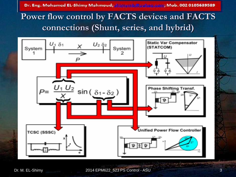
Power flow control by FACTS devices and FACTS
connections (Shunt, series, and hybrid)
Dr. M. EL-Shimy 3 2014 EPM622_523 PS Control - ASU
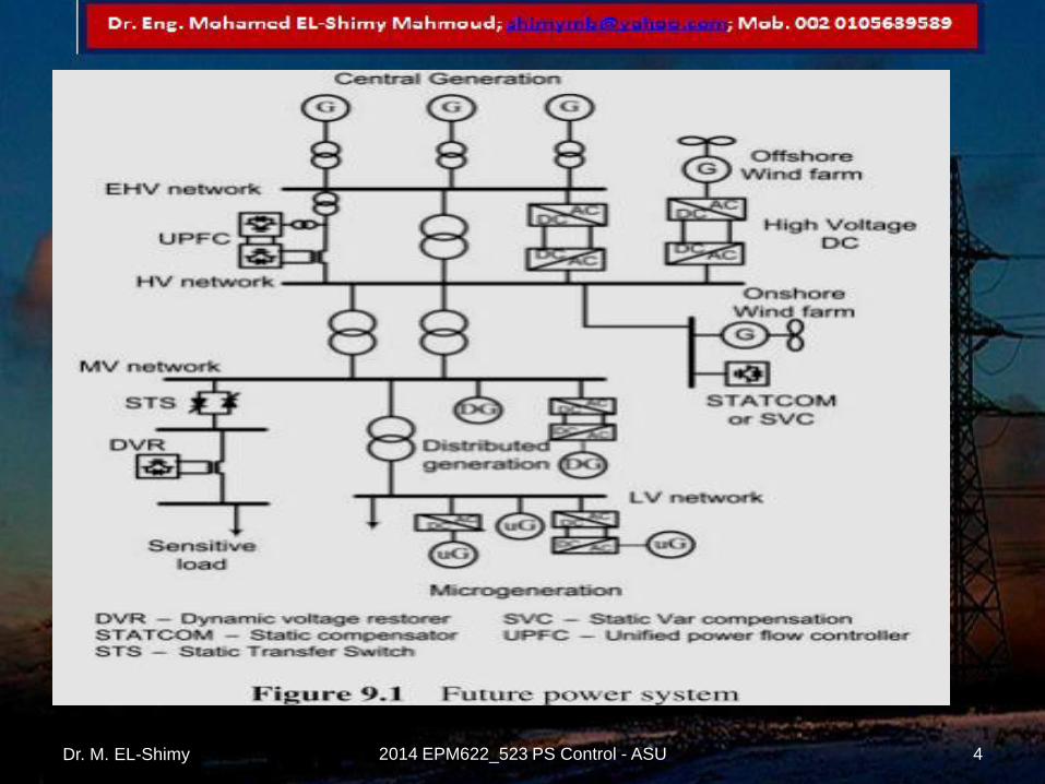
Dr. M. EL-Shimy 4 2014 EPM622_523 PS Control - ASU

Dr. M. EL-Shimy 5 2014 EPM622_523 PS Control - ASU

Dr. M. EL-Shimy 6 2014 EPM622_523 PS Control - ASU
Static VAR
Compensators (SVCs)
Dr. M. EL-Shimy 2014 EPM622_523 PS Control - ASU 7
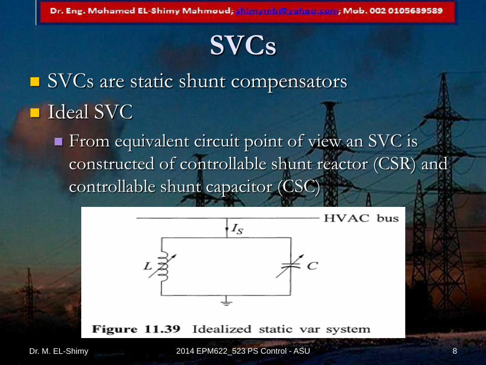
SVCs SVCs are static shunt compensators
Ideal SVC
From equivalent circuit point of view an SVC is
constructed of controllable shunt reactor (CSR) and
controllable shunt capacitor (CSC)
Dr. M. EL-Shimy 8 2014 EPM622_523 PS Control - ASU

An ideal SVC can fix the AC voltage a specific
desired value given that the reactive power
capability limits of an ideal SVC are infinite and
the response time is zero
Dr. M. EL-Shimy 9 2014 EPM622_523 PS Control - ASU

Realistic SVCs do not have infinite capacity and
their response time is limited
Dr. M. EL-Shimy 10 2014 EPM622_523 PS Control - ASU
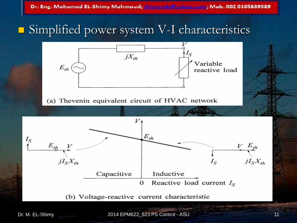
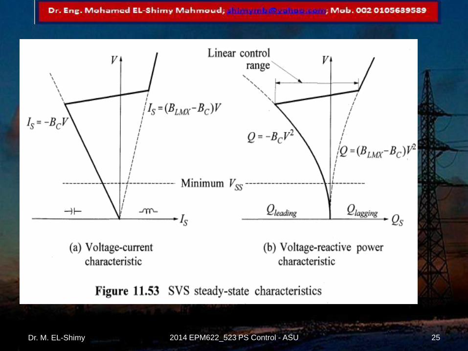
Simplified power system V-I characteristics
Dr. M. EL-Shimy 11 2014 EPM622_523 PS Control - ASU

Dr. M. EL-Shimy 12 2014 EPM622_523 PS Control - ASU
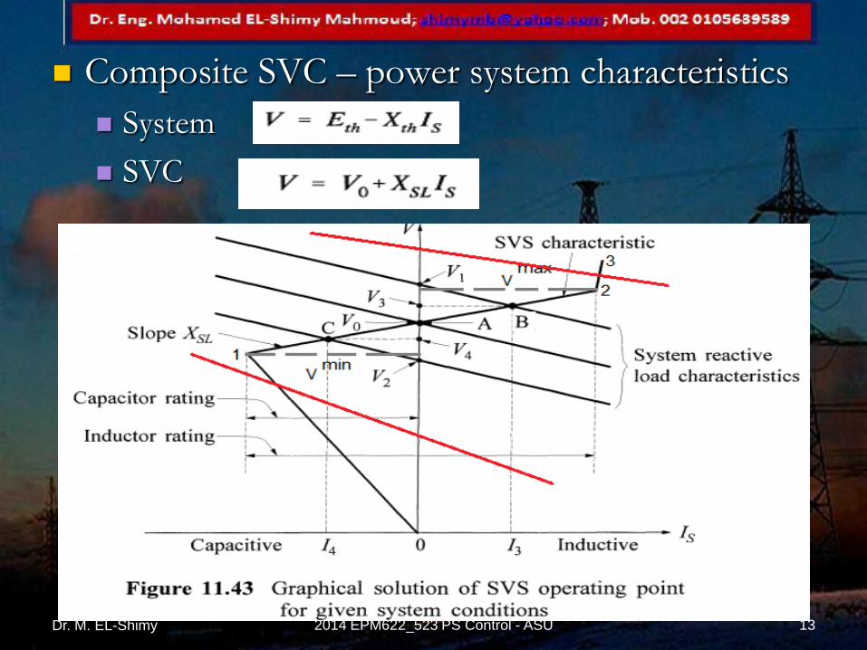
Composite SVC – power system characteristics
System
SVC
Dr. M. EL-Shimy 13 2014 EPM622_523 PS Control - ASU

Effect of switching capacitor
Dr. M. EL-Shimy 14 2014 EPM622_523 PS Control - ASU

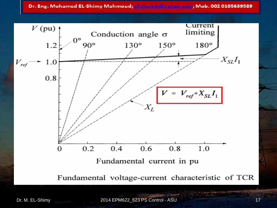
Thyristor Controlled Reactors (TCRs)
Dr. M. EL-Shimy 15 2014 EPM622_523 PS Control - ASU
Dr. M. EL-Shimy 16 2014 EPM622_523 PS Control - ASU
Dr. M. EL-Shimy 17 2014 EPM622_523 PS Control - ASU

Dr. M. EL-Shimy 18 2014 EPM622_523 PS Control - ASU
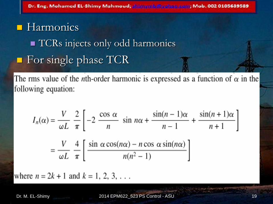
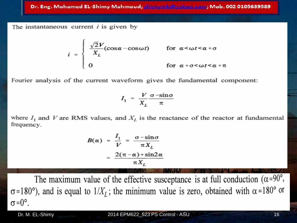
Harmonics
TCRs injects only odd harmonics
For single phase TCR
Dr. M. EL-Shimy 19 2014 EPM622_523 PS Control - ASU

Dr. M. EL-Shimy 20 2014 EPM622_523 PS Control - ASU

Dr. M. EL-Shimy 21 2014 EPM622_523 PS Control - ASU

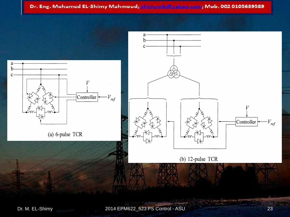
Three phase TCRs
Delta connected all triple harmonics are
eliminated by the connection
In Y-connection the harmonics are of the same
orders as the single phase TCR
Dr. M. EL-Shimy 22 2014 EPM622_523 PS Control - ASU
Dr. M. EL-Shimy 23 2014 EPM622_523 PS Control - ASU
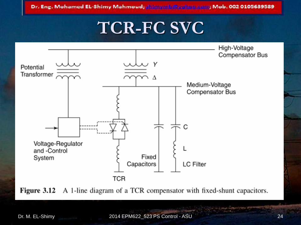
TCR-FC SVC
Dr. M. EL-Shimy 24 2014 EPM622_523 PS Control - ASU
Dr. M. EL-Shimy 25 2014 EPM622_523 PS Control - ASU

Examples
Dr. M. EL-Shimy 2014 EPM622_523 PS Control - ASU 26

Dr. M. EL-Shimy 27 2014 EPM622_523 PS Control - ASU
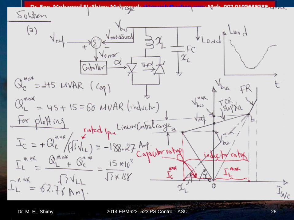
Dr. M. EL-Shimy 28 2014 EPM622_523 PS Control - ASU
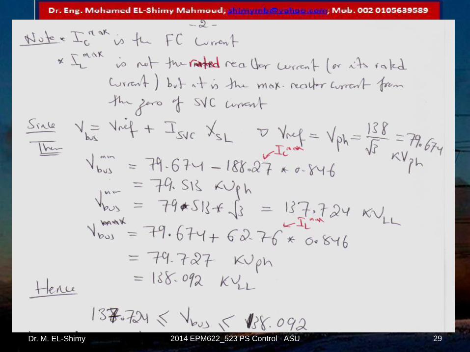
Dr. M. EL-Shimy 29 2014 EPM622_523 PS Control - ASU

Dr. M. EL-Shimy 30 2014 EPM622_523 PS Control - ASU

Dr. M. EL-Shimy 31 2014 EPM622_523 PS Control - ASU

Dr. M. EL-Shimy 32 2014 EPM622_523 PS Control - ASU
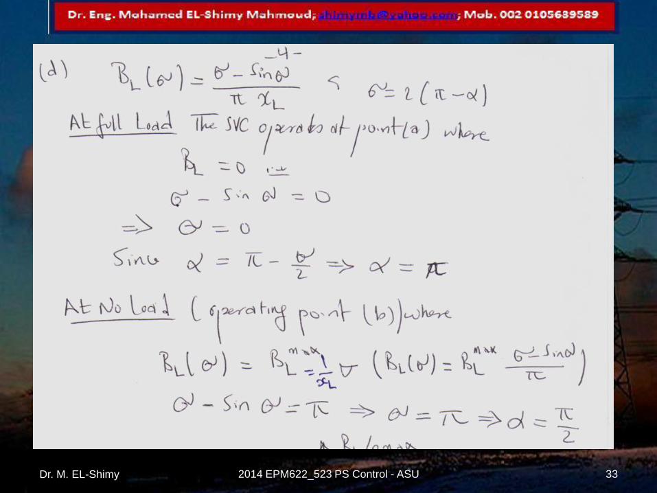
Dr. M. EL-Shimy 33 2014 EPM622_523 PS Control - ASU

Dr. M. EL-Shimy 34 2014 EPM622_523 PS Control - ASU

Report
Dr. M. EL-Shimy 2014 EPM622_523 PS Control - ASU 35
Dr. M. EL-Shimy 36 2014 EPM622_523 PS Control - ASU
SVC Voltage Regulator
Dr. M. EL-Shimy 2014 EPM622_523 PS Control - ASU 37
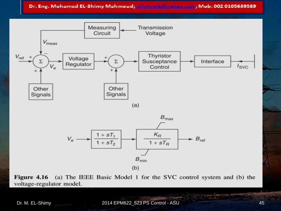
The SVC voltage regulator processes the
measured system variables and generates an
output signal that is proportional to the desired
reactive-power compensation. Different control variables and transfer functions of the voltage
regulator are used, depending on the specific SVC application.
The measured control variables are compared with a reference signal,
usually Vref , and an error signal is input to the controller transfer
function.
The output of the controller is a per-unit susceptance signal Bref , which
is generated to reduce the error signal to zero in the steady state.
The susceptance signal is subsequently transmitted to the gate pulse–
generation circuit.
Dr. M. EL-Shimy 38 2014 EPM622_523 PS Control - ASU

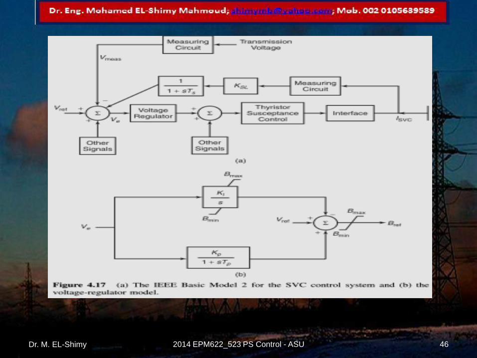
Implementations of current droop
(slope) in the voltage regulator The SVC current is
explicitly measured and
multiplied by afactor
KSL representing current
droop before feeding as
a signal VSL to the
summing junction.
RR = response rate
Dr. M. EL-Shimy 39 2014 EPM622_523 PS Control - ASU

In certain cases, it may be difficult to faithfully
obtain the current signal.
This occurs when the SVC is operating close to its
floating state, that is, zero MVA reactive power.
The current signal then comprises a
predominant harmonic component and a
fundamental resistive component corresponding
to the real losses in SVC.
Dr. M. EL-Shimy 40 2014 EPM622_523 PS Control - ASU
To overcome this problem, in certain SVC
controllers the reactive power is computed and
fed back instead of using the SVC current.
The reactive-power signal is calculated by
multiplying the phase currents in SVC by a
fundamental-frequency voltage lagging behind
the actual phase voltage by 90o.
Dr. M. EL-Shimy 41 2014 EPM622_523 PS Control - ASU

The other easily
realizable option is the
susceptance-droop
feedback demonstrated
It is implicitly assumed
that the SVC bus voltage
remains close to 1 pu;
thus the SVC current
that is strictly equal to
Bref
Dr. M. EL-Shimy 42 2014 EPM622_523 PS Control - ASU

The previous loop can be
simplified to the gain-
time constant form
Dr. M. EL-Shimy 43 2014 EPM622_523 PS Control - ASU
Dr. M. EL-Shimy 44 2014 EPM622_523 PS Control - ASU
Dr. M. EL-Shimy 45 2014 EPM622_523 PS Control - ASU
Dr. M. EL-Shimy 46 2014 EPM622_523 PS Control - ASU
SVC Applications
Dr. M. EL-Shimy 2014 EPM622_523 PS Control - ASU 47

SVC Applicatio
ns
Increase in steady-state
power-transfer capacity
Enhancement of
transient stability
Augmentation of power-system
damping SVC mitigation
of subsynchro
nous resonance
(SSR)
Prevention of voltage instability
Improvement of
HVDC link performanc
e
Dr. M. EL-Shimy 48 2014 EPM622_523 PS Control - ASU
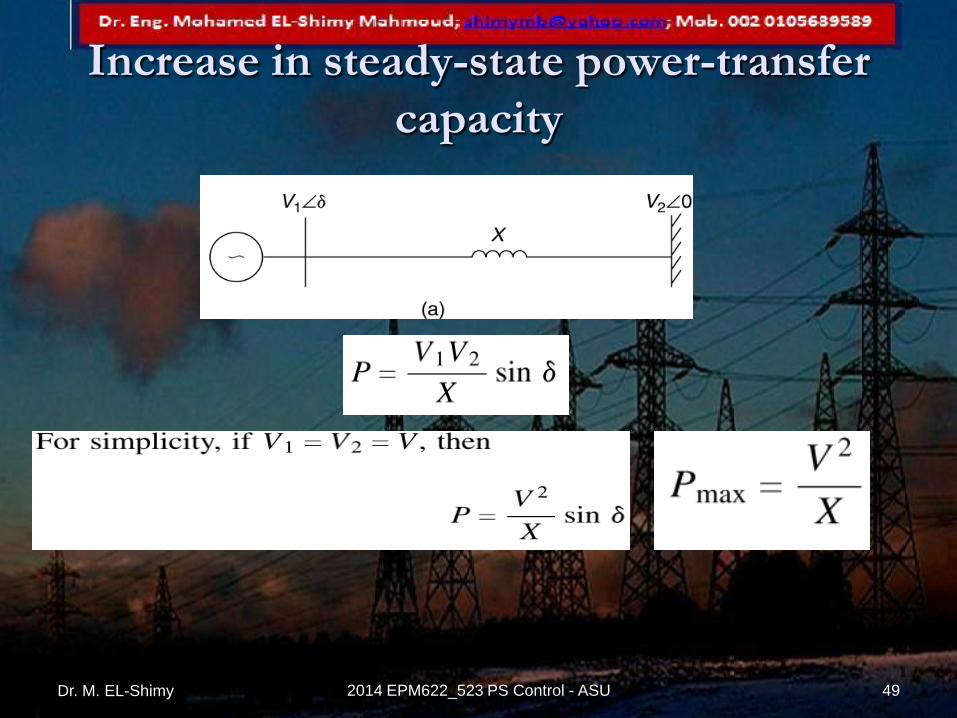
Increase in steady-state power-transfer
capacity
Dr. M. EL-Shimy 49 2014 EPM622_523 PS Control - ASU
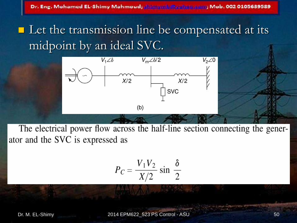
Let the transmission line be compensated at its
midpoint by an ideal SVC.
Dr. M. EL-Shimy 50 2014 EPM622_523 PS Control - ASU

Dr. M. EL-Shimy 51 2014 EPM622_523 PS Control - ASU

Dr. M. EL-Shimy 52 2014 EPM622_523 PS Control - ASU

Enhancement of transient stability
Dr. M. EL-Shimy 53 2014 EPM622_523 PS Control - ASU
STATCOM (or SSC)
Dr. M. EL-Shimy 2014 EPM622_523 PS Control - ASU 54
The STATCOM (or SSC) is a shunt-connected
reactive-power compensation device that is
capable of generating and / or absorbing
reactive power and in which the output can be
varied to control the specific parameters of an
electric power system.
A STATCOM connected to the distribution
circuits is normally called a D-STATCOM.
Dr. M. EL-Shimy 55 2014 EPM622_523 PS Control - ASU
It is in general a solid-state switching converter
capable of generating or absorbing
independently controllable real and
reactive power at its output terminals
when it is fed from an energy source or energy-storage device at its input terminals.
REM: SVCs can not generate or absorb active power
Dr. M. EL-Shimy 56 2014 EPM622_523 PS Control - ASU

STATCOM applications
Dynamic voltage control in transmission and
distribution systems;
Power-oscillation damping in power transmission
systems;
Transient stability enhancement;
Voltage flicker control; and
Control of not only reactive power but also (if
needed) active power in the connected line, requiring
a dc energy source.
Dr. M. EL-Shimy 57 2014 EPM622_523 PS Control - ASU

STATCOM Operation
Dr. M. EL-Shimy 58 2014 EPM622_523 PS Control - ASU

Dr. M. EL-Shimy 59 2014 EPM622_523 PS Control - ASU

V-I Characteristics
Unlike the SVC,
the STATCOM can provide
full capacitive-reactive power
atany system voltage - even as
low as 0.15 pu.
It is also capable of yielding
the full output of capacitive
generation almost
independently of the system
voltage (constant-current
output at lower voltages).
Dr. M. EL-Shimy 60 2014 EPM622_523 PS Control - ASU

D-STATCOM for load compensation
Dr. M. EL-Shimy 61 2014 EPM622_523 PS Control - ASU

Dr. M. EL-Shimy 62 2014 EPM622_523 PS Control - ASU

Dr. M. EL-Shimy 63 2014 EPM622_523 PS Control - ASU


