Zn 3 (btc) 2 AS ADSORBENT FOR GAS CARBON DIOXIDE AND METHANE MOHD FATHI BIN MUHAMMAD A thesis submitted in fulfillment of the requirement for the award of the degree of Bachelor of Chemical Engineering (Gas Technology) FACULTY OF CHEMICAL AND NATURAL RESOURCES ENGINEERING UNIVERSITY MALAYSIA PAHANG APRIL 2009
Transcript
Zn3(btc)2 AS ADSORBENT FOR GAS CARBON DIOXIDE AND METHANE
MOHD FATHI BIN MUHAMMAD
A thesis submitted in fulfillment of the
requirement for the award of the degree of
Bachelor of Chemical Engineering (Gas Technology)
FACULTY OF CHEMICAL AND NATURAL RESOURCES ENGINEERING
UNIVERSITY MALAYSIA PAHANG
APRIL 2009
vii
ABSTRACT
Adsorption is a process, which a substance in a gas or liquid becomes attached to
a solid. This research is carried out in order to develop the storage from metal organic
framework (MOFs) by adsorption application process. MOFs are crystalline compounds
consisting of metal ions or clusters coordinated to often rigid organic molecules to form
one-, two-, or three-dimensional structures that can be porous. MOFs are capable of
storing large amount of gases. Zn3(btc)2 is one of MOFs and it promising storage
materials. During this study, the adsorbent, Zn3(btc)2 has been developed and
characterized as a storage for the carbon dioxide and methane The characteristic of
Zn3(btc)2 as adsorbent was investigated with two parameter which is pressure and time.
For the carbon dioxide, the pressures that were used are 2.0 bars, 4 bar and 6.0 bars and
for the methane, the pressure that were used are 1.0 bar, 1.5 bars and 2.0 bars.
Meanwhile, the parameter of time that used for both gases were same which are 1 hour,
2 hours, 3 hours and 4 hours. From this experiment, it was showed that, the weight of the
sample after adsorption for both gases was increased. The experiment result showed that,
methane gas was adsorbed more into Zn3(btc)2 compared to carbon dioxide gas This is
because methane has smaller molecule size compare to carbon dioxide molecules which
is 108.70 ppm and 116.3 ppm respectively. The rate of adsorption for both gases is low
because the Zn3(btc)2 sample was not in crystallized form. This is as there are no proper
autoclaves to synthesis the sample at 393 K and 12 hour. The characteristic of Zn3(btc)2
was investigated using Scanning Electron Microscope (SEM) in order to observe the
structure of the Zn3(btc)2 before and after adsorption. From the observation, it was
showed that the structure of Zn3(btc)2 was changed after the adsorption occurred. It is
shown that the Zn3(btc)2 structure was expand and the amount of pore was decreased.
From the result analysis, it was showed that the adsorption rate was affected more by
pressure parameter compare to time parameter . As a conclusion, pressure and time of
adsorption will affected the rate of adsorption however; the pore size of sample is still
the most essential factor for an effective adsorption.
viii
ABSTRAK
Penyerapan adalah proses dimana gas atau cecair diserapkan ke dalam pepejal.
Penyelidikan ini adalah bertujuan untuk mengkaji dan menghasilkan “Metal Organic
Frameworks (MOFs)” sebagai simpanan untuk gas dengan mengaplikasikan proses
penyerapan. MOFs ialah suatu campuran yang mngandungi ion metal dan kluster koordinat
untuk membentuk organik tegap dan menghasilkan struktur dimensi satu, dua, atau tiga yang
mempunyai liang. MOFs berupaya untuk menyimpan jumlah gas yang banyak. Zn3(btc)2
adalah salah satu contoh MOFs dan ia mampu untuk menyimpan gas. Melalui penyelidikan
ini ciri-ciri Zn3(btc)2 sebagai penyimpan gas karbon dioksida dan metana telah dikanal pasti.
Ciri-ciri Zn3(btc)2 sebagai penyimpan gas diuji dengan dua parameter iaitu tekanan dan masa.
Untuk karbon dioksida, tekanan yang digunakan ialah 2 bar, 4 bar dan 6 bar manakala untuk
gas metana pula adalah 1 bar, 1.5 bar dan 2 bar. Parameter masa yang digunakan pula adalah
sama bagi kedua-dua gas ini iaitu 1 jam, 2 jam, 4 jam dan 6 jam. Daripada ekperimen yang
telah dijalankan, kedua-dua berat sampel ini bertambah selepas proses penyerapan berlaku.
Gas metana menunjukan penyerapan yang paling tinggi berbanding dengan gas karbon
dioksida. Ini adalah kerana metana mempunyai saiz molekul yang lebih kecil berbanding
dengan saiz molekul karbon doiksida iaitu 108.70 ppm dan 116.3ppm. Kadar penyerapan
bagi kedua-dua gas ini rendah kerana sampel yang digunakan dalam penyelidikan ini tidak
berada dalam keadaan kristal. Ini kerana ketiadaan “autoclave” yang mampu untuk
beroperasi selama 12 jam dan pada suhu 393K. karakter sampel sebelum dan selepas telah
diuji dengan menggunakan “Scanning Electron Microscope (SEM)” bagi melihat struktur
permukaan dan liang- liang yang terdapat pada sampel itu. Daripada pemerhatian, struktur
sampel telah berubah bentuk selepas proses penyerapan berlaku. Ia menunjukkan struktur
sampel teleh berkembang dan bilangan liang-liang semakin berkurangan. Parameter tekanan
menunjukkan ia memainkan peranan yang paling utama dalam penyerapan ke dalam
Zn3(btc)2 berbanding dengan parameter masa. Sebagai kesimpulan, tekanan dan masa
mempengaruhi proses penyerapan namun saiz liang sampel adalah tetap menjadi factor
utama kepada penyerapan yang berkesan.
ix
TABLE OF CONTENTS
CHAPTER TITLE PAGE
DEDICATION v
ACKNOWLEDGEMENT vi
ABSTRACT vii
ABSTRAK viii
TABLE OF CONTENT ix
LIST OF FIGURES xii
LIST OF TABLES xiii
LIST OF SYMBOLS xiv
LIST OF ABBREVIATIONS xv
1 INTRODUCTION
1.1 Overview 1
1.2 Problem statement 3
1.3 Objective 4
1.4 Scope of study 4
1.5 Current Research 5
2 LITERATURE REVIEW
2.1 Adsorption 6
2.2 Natural Gas 7
2.3 Carbon dioxide 9
2.4 Storage and transport 12
2.5 Materials characterization 13
2.5.1 Scanning Electron Microscopy, SEM 13
2.6 Metal-Organic Frameworks 15
2.7 Summary of literature review 16
x
3 MATERIAL & METHODOLOGY
3.1 Flow chart 17
3.2 List of material and equipment 18
3.2.1 Material and apparatus 18
3.2.2 Equipment 18
3.2.3 Preparation of materials 18
3.3 Preparation of metal-organic frameworks 19
3.3.1 Preparation of Zn3(btc)2 19
3.4 Experimental procedure 19
3.4.1 Adsorption of carbon dioxide on Zn3(btc)2 19
3.4.2 Adsorption of methane gas on Zn3(btc)2 20
3.5 Principle of Operation for Characterization 21
3.5.1 Scanning Electron Microscopy 21
4 RESULT AND DISCUSSION
4.1 Introduction 22
4.2 Performance of Zn3(btc)2 as adsorbent of gas
carbon dioxide 23
4.2.1 Constant of time, 2 hours with different
gas pressure. 23
4.2.2 Constant of gas pressure, 2 bars with
different time 24
4.3 Performance of Zn3(btc)2 as adsorbent of gas
methane. 25
4.3.1 Constant of time, 2 hours with different
gas pressure 25
4.3.2 Constant of gas pressure, 2 bars with
different time 27
4.4 Comparison on adsorption of carbon dioxide and
methane gases by Zn3(btc)2 28
4.4.1 Pressure parameter. 28
4.4.2 Time parameter 30
xi
4.5 Characterization of Zn3(btc)2 by SEM analysis 32
4.5.1 Characteristic of Zn3(btc)2 sample before
adsorption process. 32
4.5.2 Characteristic of Zn3(btc)2 sample after
adsorption of carbon dioxide gas 32
4.5.3 Characteristic of Zn3(btc)2 sample after
adsorption of methane gas. 33
5 CONCLUSION & RECOMMENDATION
5.1 Conclusion 36
5.2 Recommendation 37
5.2.1. Proposed Rig Design 37
5.2.2. Characteristic of sample 38
REFERENCES 39
APPENDICES 41
xii
LIST OF FIGURE
FIGURE NO. TITLE PAGE
3.1 Flow chart of methodology 17
3.2 schematic diagram of experiment 20
4.1 Pressure of carbon dioxide gas vs weight of gas adsorb 23
4.2 Time adsorption of carbon dioxide gas Vs weight of
gas adsorb 25
4.3 Pressure vs weight of gas adsorb 26
4.4 Time adsorption of methane gas vs weight of gas adsorb 27
4.5 Graph of pressure vs weight of gas adsorb between
carbon dioxide and methane gas 28
4.6 Graph of Gibbs excess adsorption (solid symbols)
and desorption (empty symbols) isotherms for methane 30
4.7 Graph of time vs weight of gas adsorb between
carbon dioxide gas and methane gas 30
4.8 SEM image of the Zn3(btc)2 sample before the
adsorption process occurs 32
4.9 SEM image of the Zn3(btc)2 sample after adsorption
for 2 bars and 2 hours 32
4.10 SEM image of the Zn3(btc)2 sample after adsorption
for 2 bars and 6 hours 33
4.11 SEM image of the Zn3(btc)2 sample after adsorption
for 1 bar and 2 hours 33
4.12 SEM image of the Zn3(btc)2 sample after adsorption
for 2 bar and 2 hours 34
xiii
LIST OF TABLES
TABLE NO. TITLE PAGE
2.1 Properties of methane gas 8
2.2 Properties of carbon dioxide gas 11
2.3 Summary of literature review 16
4.1 Result for constant time (2 hr) and different gas pressure. 23
4.2 Result for constant pressure (2 bars) and different
time of adsorption. 24
4.3 Result for constant time, 2 hr and different gas pressure. 25
4.4 Result for constant pressure, 2 bars and different time
of adsorption. 27
4.5 Methane adsorption capacity at 303 K 29
xiv
LIST OF SYMBOLS
CO2 – Carbon dioxide
CH4 – Methane
CO – Carbon monoxide
C2H4 – Ethylene
C2H6 – Ethane
DMF – n,n-dimethylformamide
K – Kelvin
°C – Celsius
tm – Atmosphere
% – Percent
G – Gram
L – Liter
P – Pressure
T – Temperature
Z – Atomic number
hr – Hour
b - Bar
xv
LIST OF ABBREVIATIONS
LNG – Liquefied natural gas
CNG – Compressed natural gas
BSE – Back scattered electrons
SEI – Scanning electron imaging
ppm – Parts per million
nm – Nano meter
Mpa – Mega Pascal
SEM – Scanning Electron Microscope
EDS – Energy dispersive spectrometer
WDS – Wavelength dispersive spectrometer
CRT – Cathode-ray tube
MOFs – Metal Organic-Frameworks
STP – Standard Temperature Pressure
US – United State
HFCs – Hydro fluorocarbons
GWP – Global warming potential
R744 – CO2 refrigerant
R-12 – Dichlorodifluoromethane
RTECS – Registry of Toxic Effects of Chemical Substances
EINES – European Inventory of Existing Commercial Chemical Substances
xvi
LIST OF APPENDICES
APPENDIX TITLE PAGE
A Rig of Experiment 41
B Scanning Electron Microscope 42
C Zn3(btc)2 sample 43
CHAPTER 1
INTRODUCTION
1.1 Overview
In recent years, there is a growing demand for light and heavy duty vehicles
driven with compressed natural gas (CNG) and in very few cases with liquefied
natural gas (LNG). Natural gas (NG) has a considerable advantage over conventional
fossil fuels both from an environmental point of view and due to the natural
abundance and resources. The main component of natural gas is methane, with a high
heat of combustion. The combustion of methane produces the smallest amount of
carbon dioxide per unit of heat produced among fossil fuels. Thus a further
improvement of natural gas driven vehicles is a key issue for the development of
environmentally friendly transportation systems. However, efficient storage and
transportation of this source of clean energy is still a key issue. One of the most
significant problems to be addressed in this regard is that methane is in a
supercritical state near room temperature.
The most common methods of natural gas storage worldwide are liquefaction
(due to its supercritical state, it is impossible to liquefy methane at room temperature)
and compression of natural gas at room temperature and 200–300 bar (T.L. Cook et
al., 1999). LNG offers an energy density comparable to petrol and diesel fuels, but
the necessity to store it in expensive cryogenic tanks and the boil-off losses have
prevented widespread commercial applications, especially for small vehicles. The
main disadvantage of the second method is its lower energy density per unit volume
2
compared to conventional fuels (J.Alcaniz-Monge et al., 1997). CNG has a specific
volumetric storage capacity about 240 v/v at 200 bars, which represents the volume
of stored methane at ambient conditions (1 bar, 303 K) per unit volume of vessel.
This is about 2.6 times lower than for natural gas in the liquid state (R.F. Cracknell et
al., 1993).
Natural gas has a considerable advantage over conventional fossil fuels both
from an environmental point of view and due to the natural abundance and resources.
The main component of natural gas is methane, with a high heat of combustion. The
combustion of methane produces the smallest amount of carbon dioxide per unit of
heat produced among fossil fuels. Thus a further improvement of natural gas driven
vehicles is a key issue for the development of environmentally friendly transportation
systems (J.Alcaniz-Monge. et al., 1997).
But today, engineer find the another way to store the gas that more safety and
cheaper. Natural gas is one of the examples of gas that can be store in metal organic
such as activated carbons, carbon nanotubes, porous polymers, M41S materials,
zeolites and porous ceramics. We know that an efficient material for adsorptive gas
storage should have a high specific surface area. Therefore, porous solids are the
most promising candidates. However, consideration of the area only is not enough to
obtain an efficient material. A key factor determining the interaction of methane with
the pore wall is the size of the pore. The methane adsorbent should also have a low
heat of adsorption, and high heat capacity (Mota, J. B. P et al., 1995).
However, efficient storage and transportation of this source of clean energy is
still a key issue. One of the most significant problems to be addressed in this regard
is that methane is in a supercritical state near room temperature. An efficient material
for adsorptive gas storage should have a high specific surface area. Therefore, porous
solids are the most promising candidates. However, consideration of the area only is
not enough to obtain an efficient material. A key factor determining the interaction of
methane with the pore wall is the size of the pore. Numerical simulations for the
adsorption of methane have shown that the maximum density of the adsorbed phase
3
is attained within pores 11.2–11.4 Å in diameter .The methane adsorbent should also
have a low heat of adsorption, and high heat capacity
Among these, activated carbons, carbon nanotubes, porous polymers, M41S
materials, zeolites and porous ceramics have been regarded as promising media for
efficient reversible storage of methane via physisorption Metal-organic frameworks
(MOFs) developed recently, have shown promising properties for applications in gas
storage due to the large surface areas and well-defined pore sizes. Initial reports for
MOFs indicated a high value of gas storage at moderate temperatures and pressures.
Recent studies of methane storage in MOFs (35 bar 298 K) report capacities ranging
from 213 cm3 (STP) g
−1 in [Cu(O2CRCO2)] (R = trans-C6H4CH=CH) to 240 cm
3
(STP) g−1
in IRMOF-6. IRMOFs have the composition Zn4O(L)3 (L = Linker). In
IRMOF-6 benzocyclobutene-3,6-dicarboxylate is used as the linker. Computer
simulations for an artificially constructed but until now not synthesized material
IRMOF-993 (L = 9,10-anthracenedicarboxylate) show, that this structure should
surpass all methane storage capacities reported so far.
1.2 Problem statement
Today application of methane as fuel is increasing drastically due to the
application of carbon dioxide also increased. Increasing of demand of gas was
producing the problem in storing the gas. Research is being conducted on many
fronts in the gas storage field to help identify new improved and more economical
ways to store gas. It conducted by the United State, US Energy department is
showing that salt formations can be chilled allowing for more gas to be stored. In
Sweden a new type of storage facility has been built, called "lined rock cavern”. This
storage facility consists of installing a steel tank in a cavern in the rock of a hill and
surrounding it with concrete. In transports, it quit dangerous to bring the tank contain
methane with high pressure. Today, as a promising method, the storage of carbon
dioxide and methane as adsorbed gas in porous materials is discussed. The
4
development of new materials suitable for carbon dioxide and methane gas
adsorption is an existing challenge and the research is still running.
MOFs is one of the most effective adsorbent for carbon dioxide and methane
gas. Besides it can store high volume of gas and easy to found in the market. The
storing of gases in metal organic framework facing problems where it is cannot
afford high gas storage capacity. Besides that, methane is in a supercritical state near
room temperature and it danger to the consumers. So it is impossible to liquefied
methane at room temperature and compression of methane at room temperature is
about 200-300 bar.
1.3 Objective
The objectives of this research are:
i. To prepare Zn3(btc)2 as adsorbent for carbon dioxide and methane gases.
ii. To study the characteristic of Zn3(btc)2 as adsorbent of carbon dioxide and
methane gases.
iii. To study the rate adsorption of carbon dioxide and methane in Zn3(btc)2
sample.
1.4 Scope of study
The scopes of study for this research are:
i. To identify the impact of using Zn3(btc)2 as storage medium for carbon
dioxide and methane gases.
ii. The characterization of Zn3(btc)2 as adsorbent of carbon dioxide and methane
gases.
iii. To study the performance of Zn3(btc)2 as adsorbent when changing the
pressure and time adsorption.
5
1.5 Current Research
Porous metal-organic frameworks (MOFs) have recently gained much
attention as promising materials for gas adsorption. These materials are synthesized
in a self-assembly process in which metal vertices are interconnected by organic
linkers. As a result of this building block approach, these materials offer the
possibility to tune host / guest interactions and therefore to tailor them rationally for
specific adsorption applications. The molecular simulations are used to study carbon
dioxide and methane adsorption in Zn2(bdc)2dabco MOFs (Gubbins et al., 1997).
Recently, people always talk about environmental protection. Natural gas has
a considerable advantage over conventional fossil fuels both from an environmental
point of view and due to the natural abundance and resources. The main component
of natural gas is methane, with a high heat of combustion. The combustion of
methane produces the smallest amount of carbon dioxide per unit of heat produced
among fossil fuels. Thus a further improvement of methane driven vehicles is a key
issue for the development of environmentally friendly transportation systems.
Carbon capture and storage is an approach to mitigate global warming by capturing
carbon dioxide from large point sources such as fossil fuel power plants and storing
it instead of releasing it into the atmosphere. Although carbon dioxide has been
injected into geological formations for various purposes, the long term storage of
carbon dioxide is a relatively untried concept and as of 2007, no large scale power
plant operates with a full carbon capture and storage system.
CHAPTER 2
LITERATURE REVIEW
2.1 Adsorption
Adsorption is a process, similar to absorption, by which a substance in a gas
or liquid becomes attached to a solid. The substance can be a pollutant, called an
adsorbate, which is attracted to the surface of a special solid. Adsorption occurs
naturally, but industrialists have perfected adsorption methods to clean up hazardous
waste or purify drinking water.
Tiny chemical particles suspended in another phase of matter, meaning in the
air as a gas or in water as a liquid, are sometimes considered contaminants. These
tiny particles can be separated from that phase, called the adsorbent, to enter a
different phase. A material of another phase, like the solid carbon, preferentially
targets these particles and bonds the adsorbate to its surface. The remaining air or
liquid has been purified. This differs from absorption where the particles never
change phase, but enter pores of the solid along with the accompanying air or water
(Barton et al., 1984).
Natural or organic methods of adsorption take place all the time. For example,
the ocean adsorbs carbon dioxide in the atmosphere, which effects climate and
atmospheric temperature. Early humans observed that if they charred a piece of bone
all the way through, they could put the bone in food mixtures, like sugar water, and it
would collect polluting particles that weren't edible, thereby purifying the food.
7
Particles colored in our visible spectrum, as well as those with strong odors, are
easiest to adsorb (Komodromos et al., 1992).
It is important to harness the power of adsorption in battling modern chemical
hazards. Some solids are ideal for adsorption. They have a lot of surface area for
their volume because they are pockmarked with micropores. Industrial and
commercial uses for adsorption filters vary. For example, carbon makes cold
drinking water taste better. A carbon filter can be heated to clean the surface of
adsorbates and reused. Activated alumina removes harmful chemicals like fluoride
and arsenic from liquids. Synthetic resins can clean up highly hazardous spills, such
as nerve gas, in areas that might have high temp eratures, like near explosives.
2.2 Natural Gas
Natural gas is a gaseous fossil fuel consisting primarily of methane but
including significant quantities of ethane, propane, butane, and pentane. When
heavier hydrocarbons removed it can use as a consumer fuel as well as carbon
dioxide, nitrogen, helium and hydrogen sulfide. It is found in oil fields (associated)
either dissolved or isolated in natural gas fields (non-associated), and in coal beds
kwon as coalbed methane. When methane-rich gases are produced by the anaerobic
decay of non-fossil organic material, these are referred to as biogas. Sources of
biogas include swamps, marshes, and landfills (landfill gas), as well as sewage
sludge and manure by way of anaerobic digesters, in addition to enteric fermentation
particularly in cattle (Chen et al., 1997).
Since natural gas is not a pure product, when non-associated gas is extracted
from a field under supercritical (pressure/temperature) conditions, it may partially
condense upon isothermic depressurizing--an effect called retrograde condensation.
The liquids thus formed may get trapped by depositing in the pores of the gas
reservoir.
8
One method to deal with this problem is to reinject dried gas free of
condensate to maintain the underground pressure and to allow reevaporation and
extraction of condensates.
Natural gas is often informally referred to as simply gas, especially when
compared to other energy sources such as electricity. Before natural gas can be used
as a fuel, it must undergo extensive processing to remove almost all materials other
than methane. The by-products of that processing include ethane, propane, butanes,
pentanes and higher molecular weight hydrocarbons, elemental sulfur, and
sometimes helium and nitrogen.
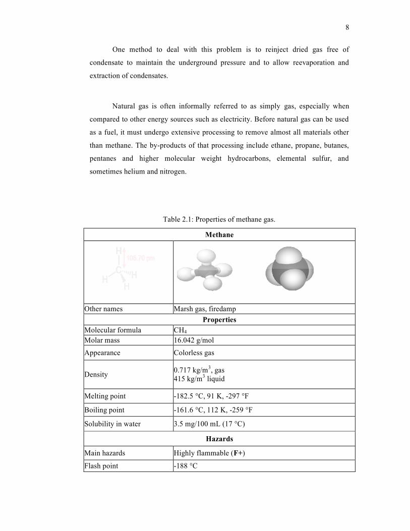
Table 2.1: Properties of methane gas.
Methane
Other names Marsh gas, firedamp
Properties
Molecular formula CH4
Molar mass 16.042 g/mol
Appearance Colorless gas
Density 0.717 kg/m
3, gas
415 kg/m3 liquid
Melting point -182.5 °C, 91 K, -297 °F
Boiling point -161.6 °C, 112 K, -259 °F
Solubility in water 3.5 mg/100 mL (17 °C)
Hazards
Main hazards Highly flammable (F+)
Flash point -188 °C
8
One method to deal with this problem is to reinject dried gas free of
condensate to maintain the underground pressure and to allow reevaporation and
extraction of condensates.
Natural gas is often informally referred to as simply gas, especially when
compared to other energy sources such as electricity. Before natural gas can be used
as a fuel, it must undergo extensive processing to remove almost all materials other
than methane. The by-products of that processing include ethane, propane, butanes,
pentanes and higher molecular weight hydrocarbons, elemental sulfur, and
sometimes helium and nitrogen.
Table 2.1: Properties of methane gas.
Methane
Other names Marsh gas, firedamp
Properties
Molecular formula CH4
Molar mass 16.042 g/mol
Appearance Colorless gas
Density 0.717 kg/m
3, gas
415 kg/m3 liquid
Melting point -182.5 °C, 91 K, -297 °F
Boiling point -161.6 °C, 112 K, -259 °F
Solubility in water 3.5 mg/100 mL (17 °C)
Hazards
Main hazards Highly flammable (F+)
Flash point -188 °C
9
2.3 Carbon dioxide
Carbon dioxide is a chemical compound composed of two oxygen atoms
covalently bonded to a single carbon atom. It can found as a gas at standard
temperature and pressure and exists in earth's atmosphere in this state. It is currently
at a globally averaged concentration of approximately 387 ppm by volume in the
earth's atmosphere. Atmospheric concentrations of carbon dioxide fluctuate slightly
with the change of the seasons, driven primarily by seasonal plant growth in the
Northern Hemisphere. Concentrations of carbon dioxide fall during the northern
spring and summer as plants consume the gas, and rise during the northern autumn
and winter as plants go dormant, die and decay. Carbon dioxide is a greenhouse gas
as it transmits visible light but absorbs strongly in the infrared and near-infrared.
Carbon dioxide is produced by all animals, plants, fungi and microorganisms
during respiration and is used by plants during photosynthesis. This is to make sugars
which may either be consumed again in respiration or used as the raw material to
produce cellulose for plant growth. It is, therefore, a major component of the carbon
cycle. Carbon dioxide is generated as a by-product of the combustion of fossil fuels
or the burning of vegetable matter, among other chemical processes. Large amounts
of carbon dioxide are emitted from volcanoes and other geothermal processes such as
hot springs and geysers.
Carbon dioxide has no liquid state at pressures below 5.1 atm, but is a solid at
temperatures below -78 °C. In its solid state, carbon dioxide is commonly called dry
ice. CO2 is an acidic oxide if we test with litmus paper with an aqueous solution, it
will turns litmus from blue to pink. CO2 is toxic in higher concentrations, 1% (10,000
ppm) will make some people feel drowsy. Concentrations of 7% to 10% can cause
dizziness, headache, visual and hearing dysfunction and unconsciousness within a
few minutes to an hour.
Carbon dioxide is used by the food industry, the oil industry, and the
chemical industry (Pierantozzi et al., 2001). It is used in many consumer products
10
that require pressurized gas because it is inexpensive and nonflammable, and because
it undergoes a phase transition from gas to liquid at room temperature at an attainable
pressure of approximately 60 bar (870 psi, 59 atm), allowing far more carbon dioxide
to fit in a given container than otherwise would. Life jackets often contain canisters
of pressured carbon dioxide for quick inflation. Aluminum capsules are also sold as
supplies of compressed gas for air guns paintball markers, for inflating bicycle tires,
and for making seltzer. Rapid vaporization of liquid carbon dioxide is used for
blasting in coal mines. High concentrations of carbon dioxide can also be used to kill
pests, such as the comman clothes moth.
Liquid and solid carbon dioxide are important refrigerants, especially in the
food industry, where they are employed during the transportation and storage of ice
cream and other frozen foods. Solid carbon dioxide is called "dry ice" and is used for
small shipments where refrigeration equipment is not practical. Liquid carbon
dioxide (industry nomenclature R744 / R-744) was used as a refrigerant prior to the
discovery of R-12 and is likely to enjoy a renaissance due to environmental concerns.
Its physical properties are highly favorable for cooling, refrigeration, and heating
purposes, having a high volumetric cooling capacity. Due to its operation at
pressures of up to 130 bars, CO2 systems require highly resistant components that
have been already developed to serial production in many sectors. In car air
conditioning, in more than 90% of all driving conditions, R744 operates more
efficiently than systems using R-13a. Its environmental advantages (GWP of 1, non-
ozone depleting, non-toxic, non-flammable) could make it the future working fluid to
replace current HFCs in cars, supermarkets, hot water heat pumps, among others.
Some applications: Coca-Cola has fielded CO2-based beverage coolers and the US
Army is interested in CO2 refrigeration and heating technology (The Coca-Cola
Company., 2006 and R744.com., 2007). By the end of 2007, the global car industry
is expected to decide on the next-generation refrigerant in car air conditioning.
11
Table 2.2 : Properties of carbon dioxide gas.
Carbon dioxide
IUPAC name Carbon dioxide
Other names Carbonic acid gas; carbonic anhydride;dry ice (solid)
Identifier
CAS number [124-38-9]
PubChem 280
EINECS number 204-696-9
RTECS number FF6400000
Properties
Molecular formula CO2
Molar mass 44.0095(14) g/mol
Appearance colorless gas
Density 1,600 g/L, solid; 1.98 g/L, gas
Melting point −57 °C (216 K) (under pressure)
Boiling point −78 °C (195 K), (sublimes)
12
2.4 Storage and transport
The major difficulty in the use of natural gas is transportation and storage
because of its low density. Natural gas pipelines are economical, but are impractical
across oceans. Many existing pipelines in North America are close to reaching their
capacity, prompting some politicians representing colder areas to speak publicly of
potential shortages.
Liquefied natural gas, LNG carriers can be used to transport liquefied natural
gas across oceans, while tank trucks can carry liquefied or compressed natural gas,
CNG over shorter distances. They may transport natural gas directly to end-users, or
to distribution points such as pipelines for further transport. These may have a higher
cost, requiring additional facilities for liquefaction or compression at the production
point, and then gasification or decompression at end-use facilities or into a pipeline.
In the past, the natural gas which was recovered in the course of recovering
petroleum could not be profitably sold, and was simply burned at the oil field (known
as flaring). This wasteful practice is now illegal in many countries. Additionally,
companies now recognize that value for the gas may be achieved with LNG, CNG,
or other transportation methods to end-users in the future. The gas is now re-injected
back into the formation for later recovery. This also assists oil pumping by keeping
underground pressures higher. In Saudi Arabia, in the late 1970s, a "Master Gas
System" was created, ending the need for flaring. Satellite observation unfortunately
shows that some large gas-producing countries still use flaring and venting routinely.
The natural gas is used to generate electricity and heat for desalination. Similarly,
some landfills that also discharge methane gases have been set up to capture the
methane and generate electricity (Malbrunot et al., 1996).
Natural gas is often stored in underground caverns formed inside depleted gas
reservoirs from previous gas wells, salt domes, or in tanks as liquefied natural gas.
The gas is injected during periods of low demand and extracted during periods of
higher demand. Storage near the ultimate end-users helps to best meet volatile
13
demands, but this may not always be practicable. With 15 nations accounting for 84%
of the world-wide production, access to natural gas has become a significant factor in
international economics and politics. In this respect, control over the pipelines is a
major strategic factor.
2.5 Materials characterization
2.5.1 Scanning Electron Microscopy, SEM
Scanning Electron Microscopy, SEM is a microscope that uses electrons
instead of light to form an image. An optical microscope use lenses to bend the light
waves and the lenses are adjusted for focus. In the SEM, electromagnets are used to
bend an electron beam which is used to produce the image on screen. By using
electromagnets, an observer can have control in how much magnification needed.
The electron beam also provides greater clarity in the image produced.
The SEM is a type of electron microscope that images the sample surface by
scanning it with a high-energy beam of electrons in a raster scan pattern. The
electrons interact with the atoms that make up the sample producing signals that
contain information about the sample's surface topography, composition and other
properties such as electrical conductivity.
The types of signals produced by an SEM include secondary electron; back


![BTC FORMBTC FORM –––– 1111 - Finance Departmentfinance.bih.nic.in/Documents/BTC-2011-Forms.pdfBihar Treasury Code – 2011 1 BTC FORMBTC FORM –––– 1111 [See Rule 10]](https://static.documents.pub/doc/80x56/5aabc1ef7f8b9aa06a8c49b2/btc-formbtc-form-1111-finance-treasury-code-2011-1-btc-formbtc.jpg)


