Page 1
FACULTY OF ELECTRICAL ENGINEERING
UNIVERSITI TEKNIKAL MALAYSIA MELAKA
FINAL YEAR PROJECT REPORT
BEKU 4894
DESIGN THE AUTO DEPTH CONTROL FOR UNMANNED
UNDERWATER VEHICLE CONTROL USING THRUSTER SYSTEM
Ismail Bin Jaaffar
Bachelor of Mechatronics Engineering
May 2013
Page 2
“I hereby declare that I have read through this report entitle “Design the auto depth control
for unmanned underwater vehicle control using thruster system” and found that it has
comply the partial fulfilment for awarding the degree of Bachelor of Mechatronic
Engineering”.
Signature : .......................................................
Supervisors Name : .......................................................
Date :
Page 3
DESIGN THE AUTO DEPTH CONTROL FOR UNMANNED UNDERWATER
VEHICLE CONTROL USING THRUSTER SYSTEM
ISMAIL BIN JAAFFAR
A report submitted in partial fulfillment of the requirements for the degree of
Bachelor of Mechatronic Engineering
Faculty of Electrical Engineering
UNIVERSITI TEKNIKAL MALAYSIA MELAKA
YEAR 2013
Page 4
I declare that this report entitle “Design the auto depth control for unmanned underwater
vehicle control using thruster system” is the result of my own research except as cited in
the references. The report has not been accepted for any degree and is not concurrently
submitted in candidature of any other degree.
Signature : ........................................................
Name : ISMAIL BIN JAAFFAR
Date :
Page 5
i
ACKNOWLEDGEMENT
I would like to express my deepest appreciation to all those who provided me the
possibility to complete this report. A special gratitude I give to my final year
project coordinator, Dr. Mariam Binti Md Ghazaly whose contribution in stimulating
suggestions and encouragement helped me to coordinate my project especially in writing
this report.
Furthermore I would also like to acknowledge with much appreciation the crucial
role of the staff of Faculty of Electrical Engineering, who gave the permission to use all
required equipment and the necessary materials to complete the task “Design the auto
depth control for unmanned underwater vehicle control using thruster system”. Special
thanks go to my team mate, who help me to assemble the parts and gave suggestion about
the task. Last but not least, many thanks go to the head of the project, Pn. Fadilah Binti
Abd Azis and Pn. Fara Ashikin Binti Ali whose have invested their full effort in guiding
the team in achieving the goal. I have to appreciate the guidance given by En. Mohd
Shahrieel Bin Mohd Aras. A special thanks to the panels especially in my project
presentation for their comment and advices that has improved my presentation skills.
Page 6
ii
ABSTRACT
In the world of underwater vehicle industries, thruster are important to control the
direction, the depth and the speed of the Remotely Operated Vehicle (ROV).There are
many types of ROV design and structure, and it all comes with different size of thruster
design. The problems that occur in the underwater where require a person to dive in the
water at a certain depth in a long time are difficult and endanger the divers’ safety. Thus,
an auto depth control system is prepared to implemented into the previous UTeM ROV
(UTeRG-ROV). This project focuses on the operation principle on which the UTeRG-
ROV can submerge and emerge using thrusters and help the UTeRG-ROV to maintain at
the specified depth. This project is to develop a prototype of thruster that has the auto
depth control which attached to the UTeRG-ROV to demonstrate the basic operation of
auto depth control as well as it operation in the water. The thrusters have its own saturation
point which means it has a maximum depth that the thrusters can submerge the UTeRG-
ROV. Therefore, ballast tank is used to submerge deeper. The maximum depth the
UTeRG-ROV can submerge by using thruster system is 0.7m. The thruster model will
thrust and submerge until it reaches a set point which is 0.5m and maintain at the
set point depth. The depth was based on pressure sensor measurement.
Page 7
iii
ABSTRAK
Dalam dunia industri kenderaan air, thruster adalah penting dalam mengawal arah,
kedalaman serta kelajuan "Remotely Operated Vehicles" (ROV). Terdapat pelbagai jenis
reka bentuk dan struktur ROV, dan ia datang dengan reka bentuk saiz thruster yang
berbeza. Masalah-masalah yang berlaku di dalam air di mana memerlukan seseorang untuk
menyelam di dalam air pada kedalaman tertentu dalam masa yang lama adalah sukar dan
membahayakan keselamatan penyelam. Oleh itu, sistem kawalan kedalaman auto
dilaksanakan ke dalam UTeM ROV (UTeRG ROV). Fokus projek ini adalah kepada
prinsip operasi di mana UTeRG-ROV boleh tenggelam dan timbul menggunakan thruster
dan ia juga membantu UTeRG-ROV untuk kekal pada kedalaman tertentu. Tujuan projek
ini adalah untuk membangunkan satu prototaip thruster yang mempunyai kawalan
kedalaman auto yang dilampirkan kepada UTeRG-ROV untuk menunjukkan operasi asas
kawalan kedalaman auto serta operasinya di dalam air. Thruster mempunyai tahap tepu
tersendiri, ini bermakna ia mempunyai kedalaman maksimum dimana tahap maksimum
thruster boleh menenggelamkan UTeRG-ROV. Oleh itu, tangki digunakan untuk
tenggelam lebih dalam lagi. Kedalaman maksimum UTeRG-ROV boleh tenggelam dengan
menggunakan sistem thruster adalah 0.7m. Thruster akan memberi tujahan dan
tenggelamkan sehingga ia mencapai titik set iaitu 0.5m dan kekal pada kedalaman titik set
yang di tentukan. Kedalaman adalah berdasarkan ukuran tekanan pada sensor.
Page 8
iv
TABLE OF CONTENTS
CHAPTER TITLE PAGE
ACKNOLEDGEMENT i
ABSTRACT ii
TABLE OF CONTENT iv
LIST OF TABLE v
LIST OF FIGURE vi
LIST OF ABBREVIATION vii
LIST OF APPENDICES viii
1 INTRODUCTION 1
2 LITERATURE REVIEW 5
2.1 MOTOR 5
2.2 PROPELLER 9
2.3 SENSOR 12
2.3.1 PRESSURE SENSOR 13
3 METHODOLOGY 17
3.1 PROCESS FLOW CHART 17
3.2 SYSTEM OVERVIEW 20
3.3 COMPONENT 20
3.3.1 MICROCONTROLLER 20
3.3.2 SK40C 21
3.3.3 RELAY 21
3.3.4 VOLTAGE REGULATOR 22
3.3.5 PRESSURE SENSOR 22
Page 9
v
CHAPTER TITLE PAGE
3.3.6 THRUSTER 23
3.4 SOFTWARE 24
3.5 SYSTEM FLOW 25
3.6 EXPERIMENTAL SET UP 27
3.6.1 EXPERIMENT 1 28
3.6.2 EXPERIMENT 2 29
3.6.3 EXPERIMENT 3 31
3.6.4 EXPERIMENT 4 32
3.6.5 EXPERIMENT 5 33
4 RESULT AND ANALYSIS 34
4.1 SENSOR TESTING RESULT 34
4.2 THRUSTER PERFOMANCE TEST RESULT 36
4.3 ACCURACY TEST RESULT 37
4.4 STABILITY TEST RESULT 38
4.5 WATERPROOF TEST RESULT 39
4.6 PROBLEM OCCURS DURING THIS PROJECT 41
5 CONCLUSION AND RECOMMENDATION 42
REFFERENCES 43
APPENDICES 45
Page 10
vi
LIST OF TABLES
TABLE TITLE PAGE
Table 2.1: Table showing the comparison of various motor technologies 5
Table 2.2: Type of analogue pressure sensor 13
Table 2.3: Comparison between piezoresistive strain gauge and capacitive
pressure sensor. 15
Page 11
vii
LIST OF FIGURE
FIGURE TITLE PAGE
Figure 1.1 The Underwater Research using ROV [4] 2
Figure 2.1 Hydraulic Thrusters 8
Figure 2.2 Example of propeller with different size [19] 9
Figure 2.3 Pitching angle of the propeller [19] 9
Figure 2.4 Propellers with different number of blade [19] 10
Figure 2.5 Angle Of Attack Diagram for Propeller Blade 11
Figure 2.6 Analogue sensor output 12
Figure 3.1 Project Flow Chart 17
Figure 3.2 Project Flow Chart 18
Figure 3.3 System Overview 20
Figure 3.4 PIC16F877A 20
Figure 3.5 Relay 22
Figure3.6 Schematic diagram of 5V voltage regulator 22
Figure 3.7 Circuit Diagram of the pressure sensor for MPX4250GP and
MPX5700GP 23
Figure 3.8 Thruster 23
Figure 3.9 DC motor and propeller 24
Page 12
viii
FIGURE TITLE PAGE
Figure 3.10 Thruster circuit simulations 24
Figure 3.11 The control board and the thruster 25
Figure 3.12 Testing pool 26
Figure 3.13 Sensor testing set up 27
Figure 3.14 Equipmental setup 28
Figure 3.15 Accuracy test set up 29
Figure 3.16 Back view of the ROV 31
Figure 3.17 The direction of disturbance 32
Figure 4.1 Graph voltage against pressure 34
Figure 4.2 Graph time against no of experiment 36
Figure 4.3 Accuracy test result 37
Figure 4.5 Graph weight against no of test 39
Figure 4.6 The weight scale 40
Figure 4.8 Control Board 41
Page 13
ix
LIST OF SYMBOLS
R - Propeller Radius, m.
T - Thrust Force, Newton.
Q - Propeller Torque, Nm
ωm - Motor Rotational Rate, rad/sec.
N - Reduction Gear Ratio.
Lift - Lift Force, N.
Drag - Drag Force, N.
A - Tunnel Cross Sectional Area
𝜃 - Angle of Inlet to Blades, rad.
a, - Effective Angle of Attack, rad.
p - Blade Pitch, rad.
𝑈𝑎 - Section Average Flow Velocity, m/s.
𝑈𝑝 - Propeler Velocity,m/ s.
𝐶𝐿𝑚𝑎𝑥 - Maximum Lift Coefficient
𝐶𝐷𝑚𝑎𝑥 - Maximum Drag Coefficient
Page 14
x
LIST OF APPENDICES
APPENDICES TITLE PAGE
A Package dimension 41
B MPX4250GP and MPX5700GP data sheet graph 42
C Experiment 1 43
D Experiment 2 44
E Experiment 3 45
F Experiment 4 46
G Experiment 5 47
H Project schedule of project activities (Gantt chart) 48
Page 15
1
CHAPTER 1
INTRODUCTION
1.1 Project Background
Remotely Operated Vehicle (ROV) is an underwater robot that designed on
purpose for surveillance, monitoring and collecting data for all underwater activities. It is a
widely safe use mechanism type for underwater vehicle serve mostly military, commercial,
and scientist needs. The main purpose of the invention of this robot is to do the operation
that hazardous to human being or at a depth which has high pressure that could affect the
system of human body. The majority of ROV’s in services are used by the oil industry for
maintaining oil rigs and pipelines [17].
ROV are divided into several classes referring to their work ability. The first class
is pure observation which is focusing on video observation and usually come in small size
and light. The second class is observation with playload option. This class of vehicle must
capable to carrying additional sensors and able to carry at least two additional sensors
without loss of original function. The third and fourth class are the work class vehicle and
the seabed working vehicle respectively [18]. The work class ROV need more space on
installing the tools to do the underwater task. In this project, the ROV that been focused on
are the observation class ROV where the ROV is smaller than the work class ROV. The
observation class of ROV is used for visual inspection and capable of carrying playload of
over 30kg. Sensor and camera are usually mounted to the observation class ROV’s to done
the routine of surveillances of subsea structures [17].
Page 16
2
1.2 Motivation
Nowadays, discovery of underwater world become more popular among scientists
and engineers. New technological devices that can submerge into the deep oceans in order
discover more about the underwater world are invented day by day. ROV is a very
common vehicle for underwater researcher to help them in investigating the underwater
species of animal and plant at the bottom of the ocean that normally human can’t do. It
emphasizes the difficulty of working to conduct these operations at such extreme depths,
where humans can’t directly interact with the malfunctioning equipment [1].
In the mean time, the ROV are already developed with thrusters in order to make
the robot to move upward, downward, forward, reverse, right and left. However, not all of
the ROV installed with the auto depth control system using thrusters or ballast tank. The
auto control system is built for maintaining the ROV at specified depth for a long time.
The system indirectly helps the researcher to record a video and take a sample at
certain depth of the sea as shown in Figure 1.1. This system is also has been applied in oil
and gas industries, where this auto depth control systems is used to help the underwater
maintenance at the offshore. The ROV needs to maintain at certain depth to do the
inspecting or monitoring job on the piping or chain.
Figure 1.1: The Underwater Research using ROV [4]
Page 17
3
1.3 Problem Statement
A ROV that named as UTeM Underwater Research Group ROV (UTeRG-ROV)
was invented in 2012. However the previous ROV do not have auto depth control system.
The ROV is loaded with thrusters which controlling upward, forward and reverse
movement of the ROV. Without the auto depth control, the ROV cannot stay at current
depth and it hard for the researcher to take out any data at a specified depth. Hence, an
enhancement of previous ROV in term of depth control is needed.
Therefore, the auto depth control for ROV using thruster system is proposed. The
auto depth control of the ROV is designed to assist the ROV in maintaining the specified
depth using thruster system.
1.4 OBJECTIVES
The objectives of this project are:
1. To design the auto depth control using thrusters system
2. To analyze the sensitivity of the chosen pressure sensor and validate the results
obtained.
1.5 SCOPES AND LIMITATION
The scopes and limitation of this project are:
1. The project only focuses on auto depth control system using pressure depth sensor by
completing the existed ROV prototype.
2. Two thruster are used to submerge the ROV.
3. The selected pitch is 450.
4. The ROV were tested in a pool with depth 1.5 meter.
5. The main source of power supply was from 12V battery.
Page 18
4
K-Chart on Designing the ROV
Vehicle
Air
Land
Sea
Underwater
Surface of Water
AUV
ROV
Pure Observation
Observation with play load
Work Class
Seabed Working Principle
Prototype
Material
Tether
Thrusters
Controller
Sensor
Propeller Motor Controller Pressure Sensor
Figure 1.2: K-Chart
Page 19
5
CHAPTER 2
LITERATURE REVIEW
This chapter discuss on the general information of the auto depth system which will
be used for UTeRG-ROV. The type of motor use and the selection of propellers in which
size, diameter, number of blade and blade pitch to the centre are included in this study as
well as pressure sensor. The facts and information are collected from reliable source and
elaborated based on the understanding of the review. The previous research information,
methodologies and design are used as references and guidelines for this project.
2.1 Motor
Motor is a machine which converts electric energy into mechanical energy. The
electric motor is one of the prime mover type for a mechanical system. Motor come in
various shapes, sizes, and technologies, each designed has its own functionality. As
information, the most common thrusters’ motor on ROV systems is selected due to its
power, availability, variety, reliability, and ease of interfaces. Motor is a one part in
thrusters that influenced the thrusters’ performance. The motor drive its shaft to move the
propeller hence the thrusters. There is several type of motor that commonly use in ROV
thrusters. The motor is selected due its ability to give out the higher torque and speed. The
low power consumption also must be considered in motor selection.
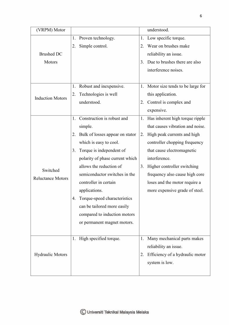
Table 2.1: Comparison of various motor technologies
Motor Type Advantages Disadvantage
Variable
Reluctance
Permenant Magnet
1. High specified tourque. 1. Suffer from high axial flux
losses.
2. Technology is not well
Page 20
6
(VRPM) Motor understood.
Brushed DC
Motors
1. Proven technology.
2. Simple control.
1. Low specific torque.
2. Wear on brushes make
reliability an issue.
3. Due to brushes there are also
interference noises.
Induction Motors
1. Robust and inexpensive.
2. Technologies is well
understood.
1. Motor size tends to be large for
this application.
2. Control is complex and
expensive.
Switched
Reluctance Motors
1. Construction is robust and
simple.
2. Bulk of losses appear on stator
which is easy to cool.
3. Torque is independent of
polarity of phase current which
allows the reduction of
semiconductor switches in the
controller in certain
applications.
4. Torque-speed characteristics
can be tailored more easily
compared to induction motors
or permanent magnet motors.
1. Has inherent high torque ripple
that causes vibration and noise.
2. High peak currents and high
controller chopping frequency
that cause electromagnetic
interference.
3. Higher controller switching
frequency also cause high core
loses and the motor require a
more expensive grade of steel.
Hydraulic Motors
1. High specified torque. 1. Many mechanical parts makes
reliability an issue.
2. Efficiency of a hydraulic motor
system is low.
Page 21
7
Table 2.1 shows the comparison of various motor topologies that could be used as a
drive for the thrusters systems. Conventional thrusters for work class underwater ROV are
driven by hydraulic motors as shown in Figure 2.1. They are normally used because
hydraulic motors are able to produce a higher specific torque when compared to traditional
electric motors (such as induction motors). This would mean that if traditional electric
motors were used to drive thrusters for ROVs, they would result in a much larger electric
thruster unit. This is undesirable, as a larger electric motor would impede the flow of water
through the propeller, as well as increase the overall space required on the vehicle to
accommodate the thruster unit and increases the overall weight of the vehicle. Hydraulic
thruster systems tend to be significantly less reliable compared to their electric
counterparts[6]. This is due to the many mechanical parts in a hydraulic thruster system
that tend to wear with time, with broken seals and water leakage into the system being
amongst some of the common faults. A hydraulic system breakdown can be very costly
because it takes a long time to repair. A typical system breakdown would involve replacing
the broken part, followed by flushing the hydraulic system and refilling it with oil, priming
and testing the system. This is a process that can take 7 to 10 hours, and operational costs
such as the ROV operator and the ROV support vessel are still being paid during this time.
Brushless
Permanent Magnet
(PM) Motors
1. Brushes are eliminated hence
removing the problem of speed
limitation and electromagnetic
interference, as well as has a
better reliability when
compared to Brushed DC
motors.
2. The amature is on the outside
stator which allows better
cooling and higher specified
outputs.
3. Permanent magnet excitation
reduces rotor losses and
improves efficiency.
1. Rare earth magnet are costly.
2. Magnet can suffer from
corrosion and demagnetization
under fault conditions.
Page 22
8
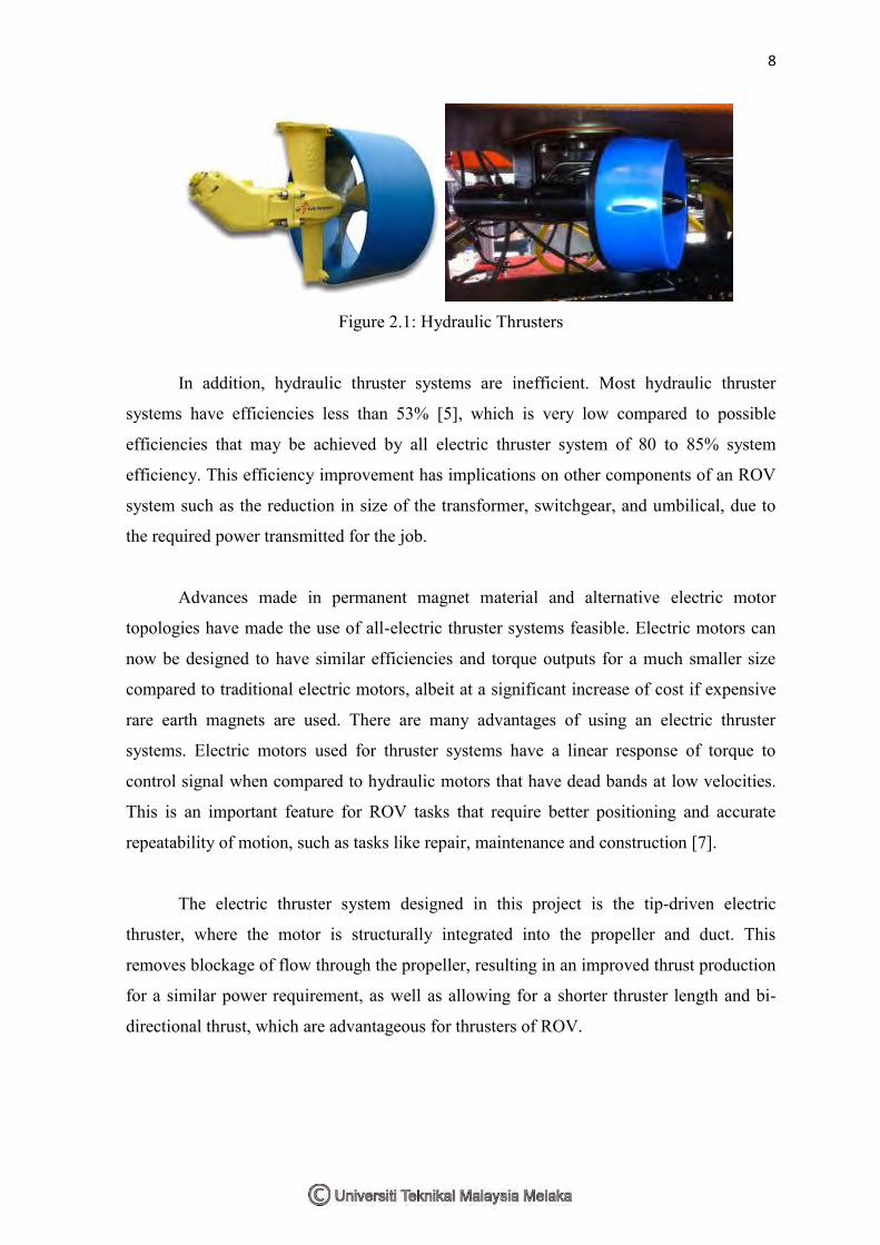
Figure 2.1: Hydraulic Thrusters
In addition, hydraulic thruster systems are inefficient. Most hydraulic thruster
systems have efficiencies less than 53% [5], which is very low compared to possible
efficiencies that may be achieved by all electric thruster system of 80 to 85% system
efficiency. This efficiency improvement has implications on other components of an ROV
system such as the reduction in size of the transformer, switchgear, and umbilical, due to
the required power transmitted for the job.
Advances made in permanent magnet material and alternative electric motor
topologies have made the use of all-electric thruster systems feasible. Electric motors can
now be designed to have similar efficiencies and torque outputs for a much smaller size
compared to traditional electric motors, albeit at a significant increase of cost if expensive
rare earth magnets are used. There are many advantages of using an electric thruster
systems. Electric motors used for thruster systems have a linear response of torque to
control signal when compared to hydraulic motors that have dead bands at low velocities.
This is an important feature for ROV tasks that require better positioning and accurate
repeatability of motion, such as tasks like repair, maintenance and construction [7].
The electric thruster system designed in this project is the tip-driven electric
thruster, where the motor is structurally integrated into the propeller and duct. This
removes blockage of flow through the propeller, resulting in an improved thrust production
for a similar power requirement, as well as allowing for a shorter thruster length and bi-
directional thrust, which are advantageous for thrusters of ROV.
Page 23
9
2.2 Propeller
The momentum theory of propellers was originally found by Rankine and Froude
shows that for a propeller actuator disc, thrust can be expected to depend on the square of
the flow velocity through the blading and that the energy efficiency of the propeller is
increased when the thrust loading on the blade is reduced [13]. This theory does not
explain deeper on how the shape of the propeller blade is related to the thrust of the ROV.
The theory of aerodynamic is closely related to the blade element theories, in which the lift
and drag forces generated from any element of the blade's cross section are added over the
total length of the blade [15]. The local angle attack at blade section is related to the lift
and drag forces. A representation of lift and drag coefficients as a function of effective
angle of attack is then required to complete the calculation of the amount of thrust and
torque. Lift and drag coefficients available for many different parts of the wing for small
angles [19].
Figure 2.2: Example of propeller with different size [19]
Figure 2.3: Pitching angle of the propeller [19]
350 450 500 400
45mmm
50mm
Page 24
10
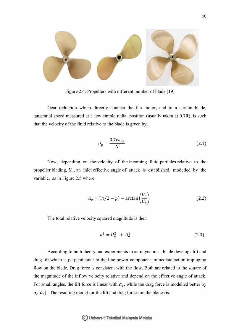
Figure 2.4: Propellers with different number of blade [19]
Gear reduction which directly connect the fan motor, and to a certain blade,
tangential speed measured at a few simple radial position (usually taken at 0.7R), is such
that the velocity of the fluid relative to the blade is given by,
𝑈𝑝 =0.7𝑟𝜔𝑚
𝑁 (2.1)
Now, depending on the velocity of the incoming fluid particles relative to the
propeller blading, 𝑈𝑎 , an inlet effective angle of attack is established, modelled by the
variable, as in Figure 2.5 where:
𝛼𝑒 = 𝜋 2 − 𝑝 − arctan 𝑈𝑎𝑈𝑝 (2.2)
The total relative velocity squared magnitude is then
𝑣2 = 𝑈𝑝2 + 𝑈𝑎
2 (2.3)
According to both theory and experiments in aerodynamics, blade develops lift and
drag lift which is perpendicular to the line power component immediate action impinging
flow on the blade. Drag force is consistent with the flow. Both are related to the square of
the magnitude of the inflow velocity relative and depend on the effective angle of attack.
For small angles, the lift force is linear with 𝛼𝑒 , while the drag force is modelled better by
𝛼𝑒 |𝛼𝑒 |.. The resulting model for the lift and drag forces on the blades is: