58


FACULTY OF ENGINEERING AND COMPUTER SCIENCE
DEPARTMENT OF MECHANICAL AND INDUSTRIAL
ENGINEERING
MECH 6611 WINTER 2007
Manufacture
of Car Engine Side Cover using CAD/CAM
(Computer Aided Design & Manufacturing).
Submitted to :
Professor: Dr. Chevy Chen
Submitted by :
Maruf Khondker(L) ID # 4806972
T. M. Shaiful Islam ID # 5815347

INDEX CHAPTER DESCRIPTION Page No
Acknowledgement 1 Abstract 2
1. CNC BASIC
1
Introduction (CNC Basic and essential Terminology) 3 Milling Machine Tools 4 Design and Manufacturing 5-6 Cutting Speed, Spindle Speed and Feed Rate 7-14 Size of Cutter 15-16 Project Machining Parameter 17
2. PROJECT 1 (Manual G-CODE based Machining)
2 Introduction 18 Generate 3D point in MS EXCEL 18-19 Project Detail Drawing and Dimension 20 Machining Picture 21-23 G-CODE for Slant, Face, Pocket & Drill Operation 23-27
3. FINAL PROJECT(CATIA based machining toolpath and G-CODE generation)
3 Project Detail Drawing and Dimension 28 Design and Optimization of Model 29-32 Machining Tool Path Generation using CATIA 33-38 Operation Sequence Step by Step 39-40 Final Part (Design + Simulation + Real Machining Part) 41
4. Third Wave AdvantEdge™ Analysis Software
4 Introduction 42 The Operational Analysis for the Project 43-48 Sample Analysis Result 49-51
5. Miscellaneous
5 Sample G-CODE of Final Project 52-54 Achievement 55 Conclusion 56 References 57

ACKNOWLEDGEMENT
We greatly appreciate the generous efforts, encouragement, and guidance of Dr. Chevy Chen throughout all stages of this project. Also we like to express our sincere gratitude to PhD student Mr. Maqsud for his friendly cooperation, helped and taught us the various things for machining from the beginning to end of the project Also, we want to acknowledge our great appreciation to Machinist John for his major contribution and assistance to machine the part.

ABSTRACT
In the era of modern technology in order to produce a competitive product with better quality and at lower cost efficiently, everybody uses powerful technologies during the product cycle. As a CNC engineer its prime need to know the appropriate uses of G-CODE and optimum design tool path. Therefore, two projects have been assigned to us to meet the requirement as a CNC engineer. First project: manual design of G-CODE used to perform machining. Final project we generate G-Code using most powerful software CATIA. One thing in this project that we took advantages of the powerful features that CATIA software has to design, generate machining tool paths, and generate G-CODE source code for the part. Then using Fagor controller 8055i post processor software enabled generates the Final G-code. The final G-Code file size was large in size (100K+ byte). The available memory in machine used in the Lab is much lower than generated G-Code. Therefore; we spilt whole G-Code in several individual file and defined machining parameter manually and also we redesign and rearrange the toolpath according to the requirement of machine. Overall those limitations of the machine increase our ability to play with G-Code and Toolpath. Furthermore we used Third Wave AdvantEdge™ which is a powerful tool for engineers; to design, setup, improve and optimize machining processes. It enables us to determine machining parameters and tooling configurations that can reduce cutting forces, temperatures, and part distortion, all offline. This reduces the need for online testing, which costs money and valuable production time.

Introduction (CNC Basic and essential Terminology)
Numerical control or numerically controlled (NC) machine tools are machines that are automatically operated by commands that are received by their processing units. NC machines were first developed soon after World War II and made it possible for large quantities of the desired components to be very precisely and efficiently produced (machined) in a reliable repetitive manner. Numerical Control (NC) was the precursor of today's Computer Numerical Control (CNC), which controls the automation of machine tools and the inherent tool processes for which they are designed. CNC, computer numerical control refers specifically to a computer "controller" that reads G-code instructions and drives a machine tool, a powered mechanical device typically used to fabricate components by the selective removal of material. G-code is a common name for the programming language that controls NC and CNC machine tools. CNC does numerically directed interpolation of a cutting tool in the work envelope of a machine. The operating parameters of the CNC can be altered via a software load program. The CNC machine tool is the servo actuator of the CAD/CAM (Computer Aided Design/Computer Aided Manufacturing) technology both literally and figuratively. CNC inherits from NC the essential character of by-the-numbers interpolation of transition points in the work envelope of a multi-axis motion platform, based on the separation of programming from operations. The set of instructions, or "program" (usually an ASCII text file in which, in its simplest form, a line of text specifies the axial coordinates of a point in the work envelope) is prepared from a blueprint or CAD file and transferred to the memory of the CNC via floppy drive, serial data interface or a network connection. Once stored in the CNC memory and selected, the program is executed by pressing the appropriate key on the machine operator panel.
Computer-aided manufacturing (CAM) is the use of computer-based software tools that assist engineers and machinists in manufacturing or prototyping product components. CAM is a programming tool that allows you to make 3D models using computer-aided design (CAD). CAM was first used in 1971 for car body design and tooling. CNC was preceded by NC (Numerically Controlled) machines, which were hard wired and their operating parameters could not be changed. ( http://en.wikipedia.org/wiki/CNC)

MILLING MACHINE TOOLS: A milling machine is a machine tool used for the shaping of metal and other solid materials. Its basic form is that of a rotating cutter which rotates about the spindle axis and a table to which the workpiece is affixed. The cutter and workpiece move relative to each other, generating a toolpath along which material is removed. Milling machines may be operated manually or by CNC (computer numerical control). There are two main types of mill: the vertical mill and the horizontal mill. In the vertical mill the spindle axis is vertically oriented. These machines are also classified as knee-type, ram-type, bed type, and planer-type. Milling cutters are held in the spindle and rotate on its axis. The spindle can generally be extended allowing plunge cuts and drilling. Most CNC milling machines or machining centers are computer controlled vertical mills with the ability to move the spindle vertically along the Z-axis. Milling is the process of machining flat, curved, or irregular surfaces by feeding the workpiece against a rotating cutter containing a multiple cutting edges. The milling machine consists basically of a motor driven spindle, which mounts and revolves the milling cutter, and a reciprocating adjustable worktable, which mounts and feeds the workpiece. Milling is a basic machinery process by which a surface is generated progressively by the removal of chips from a workpiece as it is fed to a rotating cutter in a direction perpendicular to the axis of the cutter. In some cases the workpiece remains stationary, and the cutter is fed to the workpiece. Milling operations can be classified into two broad categories: Face milling and flank milling. In face milling the generated result of the actions of the portions of the teeth located on both the periphery and the face of the cutter. Most of the cutting is done by the peripheral portions of the teeth, with the face portions providing some finishing action. In flank milling a surface is generated by teeth located on the periphery of the cutter body. The surface is parallel with the axis of rotation of the cutter. Both flat and formed surfaces can be produced by this method, the cross section of the resulting surface corresponding to the axial contour of the cutter.

A milling cutter can cut in two directions, sometimes known as climb or conventional milling. In Conventional milling Figure1 (a), the depth of the cut starts at zero thickness, and increases up to the maximum. The cut is so light at the beginning that the tool does not cut, but slides across the surface of the material, until sufficient pressure is built up and the tooth suddenly bites and begins to cut. This deforms the material (at point A on the diagram, left), work hardening it, and dulling the tool. The sliding and biting behavior leaves a poor finish on the material.
(a) (b)
Figure 1: (a) Conventional Milling and (b) Climb Milling In Climb milling figure1 (b), each tooth engages the material at a definite point, and the width of the cut starts at the maximum and decreases to zero. The chips are disposed behind the cutter, leading to easier swarf removal. The tooth does not rub on the material, and so tool life may be longer. However, climb milling can apply larger loads to the machine, and so is not recommended for older milling machines, or machines which are not in good condition.
1.0 DESIGN AND MANUFACTURING Three main steps had to be done to produce our Engine Cover:
• Sketch and Design the part.
• Optimize geometry so that modification can be accomplished easily.

• Plan and sequence for machining
• Select machining parameter and Generate machining tool paths.
• Select appropriate tool and design toolpath on the basis of tool change.
• Machine the part.
1.1 .0 Sketch and Design the Part CATIA software is used to design and modify the part of the engine cover. The part design and wireframe and surface design workbench are used to create the shape of the part during preliminary design of the part. The normal shape of the part is designed with part design workbench and the surface shape of the part is sketched with Generic Shape Design and basic surface features. To get the final shape, two main steps were done: 1.1.1 Sketch and Design:
• Create the convex shape of the engine cover using wireframe and surface design workbench.
• Create a plane and draw the preliminary sketch of the part using part design workbench.
• Create solid shape by using part design workbench.
• Create the preliminary pockets and holes of the part using part design workbench.
• Create the original shape of the part using part design workbench and modify.
1.1.2 Design the engine cover, doing fillet for some edges using part design work bench, and saving the results on a separated CATIA part file.
1.2.0 plan and sequence for machining
After designing the engine cover, new steps to take planning before starting the machining of the part and sequences of the operation. These steps are taken so that machining process time is short but the efficiency is better. The steps are below :
• studying of the part
• raw material selection
• machine selection

• tool material selection
• sequence of machining 1.3.0 Select machining parameter and Generate Machining Tool Paths
1.3.1 Selection of the machining parameter The general machining parameters are
1. Cutting speed(FMP or MPM)/spindle speed(RPM) 2. Feed rate (IPM or MMPM) 3. Depth of cut (INCH or MM) 4. Width of cut (INCH or MM) 5. Cutter size (INCH or MM) 6. Coolant
1.3.2 Cutting speed or spindle speed: Cutting speed is a importance parameter for is the speed difference between the cutting Tool and the surface of the workpiece it is operating on. Such as in a turning operation, the cutting speed is the speed of the (stationary) cutter passing over the (moving) workpiece, or in milling operations, the speed of the (stationary) workpiece moving past a (rotating) cutter. It is expressed in units of distance along the workpiece surface per time (typically surface feet per minute [sfm]. Cutting speed may be defined as the rate (or speed) at which the cutting of the tool passes over the surface of the workpiece. For a given material there will be an optimum cutting speed for a certain set of machining conditions, and from this speed the spindle speed (RPM) can be calculated. Factors affecting the calculation of cutting speed are:
• The material being machined (steel, brass, tool steel, plastic, wood)
• The material the cutter is made from (Carbon steel, High speed steel (HSS), carbide, ceramics)
• The economical life of the cutter
It is difficult to determine precise data for any metal cutting operation without knowledge of the practicalities involved. Cutting speeds are calculated on the assumption that optimum cutting conditions exist, these include:

• Metal removal rate (finishing cuts that remove a small amount of material may be
run at increased speeds)
• Full and constant flow of cutting fluid (adequate cooling and chip flushing)
• Rigidity of the machine and tooling setup (reduction in vibration or chatter)
• Continuity of cut (as compared to an interrupted cut, such as machining square section material in a lathe)
• Condition of material (mill scale, hard spots due to white cast iron forming in castings)
The cutting Speed is given as a set of constants that are available from the material manufacturer or supplier, the most common materials are available in reference books. The following table gives the cutting speeds for a selection of common materials. Table 1: Cutting speeds for various materials (Based on plain High Speed Steel cutter)
Material type meters per min feet per min
Steel (tough) 15 - 18 50 – 60
Mild steel 30-38 100-125
Cast iron (medium) 18-24 60-80
Bronzes 24-45 80-150
Brass (soft) 45-60 150-200
Aluminum 75-105 250-350
Table 2: surface cutting speed for various materials (based on Carbide cutter)
Material type meters per min feet per min
Mild steel 170 300
Cast iron (medium) 100 225
Brass (soft) 180 450
Aluminum 250 900

Table 3 Recommended Cutting Speeds for Drilling with High-Speed Steel Drills
Materials Cutting Speed (fpm)
High-Speed Steel 20-40
Mild steel 90-120
Cast iron (medium) 80-140
Bronzes 30-100
Aluminum 150-300
Spindle speed: The cutting speed is related to, but not the same as, spindle speed. The spindle speed is the rotational frequency of the spindle of the machine, measured in revolutions per minute (RPM). The preferred speed is determined based on the material being cut.
Excessive spindle speed or cutting speed will cause premature tool wear, breakages, and can cause tool chatter, all of which can lead to potentially dangerous conditions. Using the correct spindle speed for the material and tools will greatly affect tool life and the quality of the surface finish.
For a given machining operation, the cutting speed will remain constant for most situations. In milling the cutting speed will remain constant. But facing operations on a lathe where involve the machining of a constantly changing diameter, the spindle speed is changed to keep the constant speed of the cutting edge. The formula of cutting speed
Spindle speed, NDNDCS .262.012
..==
π ft/min (FPM)
(1) When inchesindiametrcutterD =
1000
.. NDCS π= m/min (MPM)
(2) When meterindiametrcutterD = Where: RPMinspeedspindleN =
From the above equations the spindle equations can be calculated as

DCSN⋅⋅
=π
12 RPM (3)
DCSN
⋅⋅
=π
1000 RPM (4)
Table 4: Calculated Spindle Speed for various materials with High Speed Steel Cutter for Milling
Materials
Spindle Speed (RPM)
Cutters Diameter(Inches)
2½ 1 1/2 1/4
Steel (tough) 75-90 190-230 380-460 760-915
Mild steel 150-190 380-475 760-950 1525-1910
Cast iron (medium) 90-120 230-305 460-610 915-1220
Bronzes 120-230 305-570 610-1145 1220-2290
Brass (soft) 230-305 570-760 1145-1525 2290-3055
Aluminum 380-540 950-1350 1910-2670 3820-5340
Table 5: Calculated Spindle Speed for various materials with High Speed Steel Cutter for Drilling
Materials
Spindle Speed (RPM)
Cutter diameter(in)
½ 1/4
High-Speed Steel 150-305 305-610
Mild steel 685-915 1375-1830
Cast iron (medium) 610-1070 1220-2140
Bronzes 230-760 460-1525
Brass (soft) 1145-2290 2290-4580
Aluminum 1140-2290 2290-4580

2. Feed rate: Another important parameter for machining is feed rate. Feed rate is the velocity at which the cutter is fed, that is, advanced against the workpiece. It is expressed in units of distance per revolution for turning and boring (typically inches per revolution or millimeters per revolution). It can be expressed thus for milling also, but it is often expressed in units of distance per time for milling (typically inches per minute or millimeters per minute), with considerations of how many teeth (or flutes) the cutter has then determining what that means for each tooth.
Therefore, feed rate is expressed
• Feed per tooth (ft)
Inches per tooth(IPT)
Millimeters per tooth (MMPT)
• Feed per revolution (fr)
Inches per revolution (IPR)
Millimeters per revolution (MMPR)
• Feed per revolution (fm, used in CNC programs)
Inches per minute (IPM)
Millimeters per minute (MMPM)
The formula for fr& fm are
Tff tr ⋅= NTff tm ⋅⋅=
where, =tf feed per tooth (IPT or MMPT)
=rf feed per revolation (IPR or MMPR)
=tf feed per minute (IPM or MMPM)
=T number of teeth of the cutter =N Spindle speed(RPM)

Feed rate is dependent on the:
• Surface finish desired.
• Power available at the spindle (to prevent stalling of the cutter or workpiece).
• Rigidity of the machine and tooling setup (ability to withstand vibration)
Strength of the workpiece (high feed rates will collapse thin wall tubing)
• Characteristics of the material being cut, chip flow depends on material type
and feed rate. The ideal chip shape is small and breaks free early, carrying
heat away from the tool and work.
When deciding what feed rate to use for a certain cutting operation, the calculation is fairly straightforward for single-point cutting tools, because all of the cutting work is done at one point (done by "one tooth", as it were). With a milling machine or jointer, where multi-tipped/multi-fluted cutting Tools are involved, and then the desirable feed rate becomes dependent on the number of teeth on the cutter. The greater the number of cutting edges, the higher the feed rate permissible: for a cutting edge to work efficiently it must remove sufficient material to cut rather than rub; it also must do its fair share of work. Table6: Recommended Feed in Inches per Tooth (ft) for High-Speed Steel Milling Cutters
Materials
End Millis
Face Mills Depth of cut 0.25 Depth of cut 0.05
Cutter diameter Cutter diameter
3/8 3/4 1and up
1/8 3/8 3/4 1 and up
Mild Steel 0.0030 0.0040
0.0050
0.0015
0.0040
0.0055
0.0070
0.004-0.011
Cast Iron 0.0025 0.0055
0.0070
0.0010
0.0035
0.0065
0.0080
0.004-0.013
Brasses and 0.0025 0.005 0.008 0.000 0.003 0.006 0.009 0.004-

Bronzes 0 0 8 5 5 0.012
Zinc Alloys 0.0040 0.0080
0.0120
0.0020
0.0050
0.0080
0.0120
0.005.0200
Aluminum Alloys
0.0030 0.0080
0.0100
0.0020
0.0030
0.0100
0.012 0.005-0.020
Magnesium Alloys
0.0030 0.0080
0.0120
0.0020
0.0040
0.0100
0.0140
0.0050.020
Plastics 0.003 0.008 0.010 0.002 0.004 0.010 0.014 0.005-0.020
Table 7: Recommended Feed Rate for Drilling High-Speed Steel Cutters
Drill Diameter (in) Drill Feed, Inches per Revolution(IPR)
1/16 to1/8 0.001-0.003
1/8 to 1/4 0.002-0.006
1/4 to 1/2 0.004-0.010
1/2 to 1 0.007-0.015
Over 1 0.015-0.025
Feed Rate Calculations-The feed rate in inches per tooth or inches per revolution must be converted into feed rate in inches per minute (IPM) before setting the feed rate on the machine. The feed rate for machining depends upon the hardness of the workpiece material, depth of cut the cutting tool material and the size of the cutting tool. The formula for converting feed rate in inches per tooth into inches per minute are given in equations (5) and (6). By using these equations, feed rate are calculated for aluminum material with High-Speed Steel cutters as below:

Table 8: Calculated feed rate in Inches per minute (IPM) for Aluminum Material with HSS cutters used in the Project.
Cutter diameters(in) Avg. Spindle Speed (RPM)
Number of teeth (T)
Feed rate(IPM)
Depth of cut 0.25
Depth of cut 0.05
Face mills (D=2½)
Milling
2½ 410 4 16.40 19.68 8.20 To
32.80
1 1150 2 23.00 27.60
1/2 2140 2 21.40 30.00
1/4 4580 2 27.48 27.48
Drilling
1/8 to 1/4 1715 2 3.28 to 9.84
1/4 to1/2 3435 2 6.56 to 16.40
3.6 Depth of Cutting
Depth of cut is another important parameter for the machining a part. It is defined as the thickness of the material removed by one pass of the cutting tool. The depth of cut of the end mill into the part surface axially. With CNC milling, it is measured in the Z axis direction. Cutting speed feed rate and depth of cut are related for machining. If depth of cut is small, the higher feed rate is allowed. For high depth of cut the feed rate is low. Because the Horse power of the machine tool depends on the removal rate of the material. Material removal rate is the product of feed rate, depth of cut and width of cut. Therefore, the formulations for Horse power, HPc=UHP.MRR.C and Material removal rate, MRR=W.H.fm Where, UHP: Unit Horse power W: Width of cut (in) H: Depth of cut, The depth of cut is also related to the diameter of the cutter. For larger diameter of cutter, higher depth of cut is allowed. For smaller diameter of cutter, smaller depth of cut is allowed. The depth of cut is one fourth of cutter diameter.

SIZE OF THE CUTTERS
Selecting the size of cutter is factor for machining. There are many variables, opinions and lore to consider, but essentially the machinist is trying to choose a tool which will cut the material to the required specification for the least cost. The cost of the job is a combination of the price of the tool, the time taken by the milling machine, and the time taken by the machinist. Larger Diameter tools can remove material faster than small ones, therefore the largest possible cutter that will fit in the job is usually chosen. When milling an internal contour, or concave external contours, the diameter is limited by the size of internal curves. The radius of the cutter must be less than or equal to the radius of the smallest arc. The tooth cuts the material, and chips of this material are pulled up the flute by the rotation of the cutter. Typically, the more teeth a cutter has, the more rapidly it can remove material. So, a 4-tooth cutter can remove material at twice the rate of a 2-tooth cutter. A roughing cutter may have serrated teeth for breaking the chips of material into smaller pieces. These teeth leave a rough surface behind. A finishing cutter may have a large number (4 or more) teeth for removing material carefully. However, the large number of flutes leaves little room for efficient swarf removal, so they are less good for removing large amounts of material. More flutes allow a higher feed rate, because there is less material removed per flute. But because the core diameter increases, there is less room for swarf, so a balance must be chosen. The flutes of a milling cutter are almost always helical. High helix angles are typically best for soft metals, and low helix angles for hard or tough metals.

Figure 2: End mill cutters Typically, finishing cutters have a higher rake angle (finish tighter helix) to given a better. Long tool is not good for machining. Long tool length with small diameter causes vibration which is very harmful for the cutter and surface quality of the workpiece. A tool held improperly or extended too far out of the tool holder can cause a multitude of problems excessive wear, chipping, breakage, vibration marks on the walls and bottom, minimum material removal per minute. Factors in CNC tool length selection include the following:
• Maintain solid shanks down to the surface being cut, by custom grinding when necessary. Fluted areas of end mills are the weakest point.
• Select only flute lengths that required: no cutting edges need extend beyond 1/32 above cut surfaces. See figure (3).
A cutter that is too small can be programmed to generate larger Radii, but will compromise other areas: vibration, cutting width (requiring more passes), tool wear, and so on

FINAL PROJECT Machining Parameter (Spindle Speed and Feed Rate) From the above discussion considering all the designing parameter needed for machining here we include our machining parameter for the Project. Furthermore; as we mentioned before, we are not allowed to use calculated spindle speed and feed rate in the lab because the goal is to learn from the course. We have enough time for designing and machining therefore; industry standard high speed machining was not considered for the project. We have to use much lower than industry standard values for safety reason. After consulting technicians in the machine shop, we decided to use values which are illustrated in table (5).
Table 9: Used spindle speed and feed rate SI Cutter Name Diameter
(in) Spindle Speed (RPM)
Feed rate (IPM)
1 Face Mill 2½ 1500 10
2 Flat End Mill 1 1500 6
3 Flat End Mill 1/2 2000 8
4 Ball-Nose End Mill 1/2 2000 8
5 Ball-Nose End Mill 1/4 3000 6
6 Dill Bit 1/2 1500 4
7 Dill Bit 1/4 1000 4
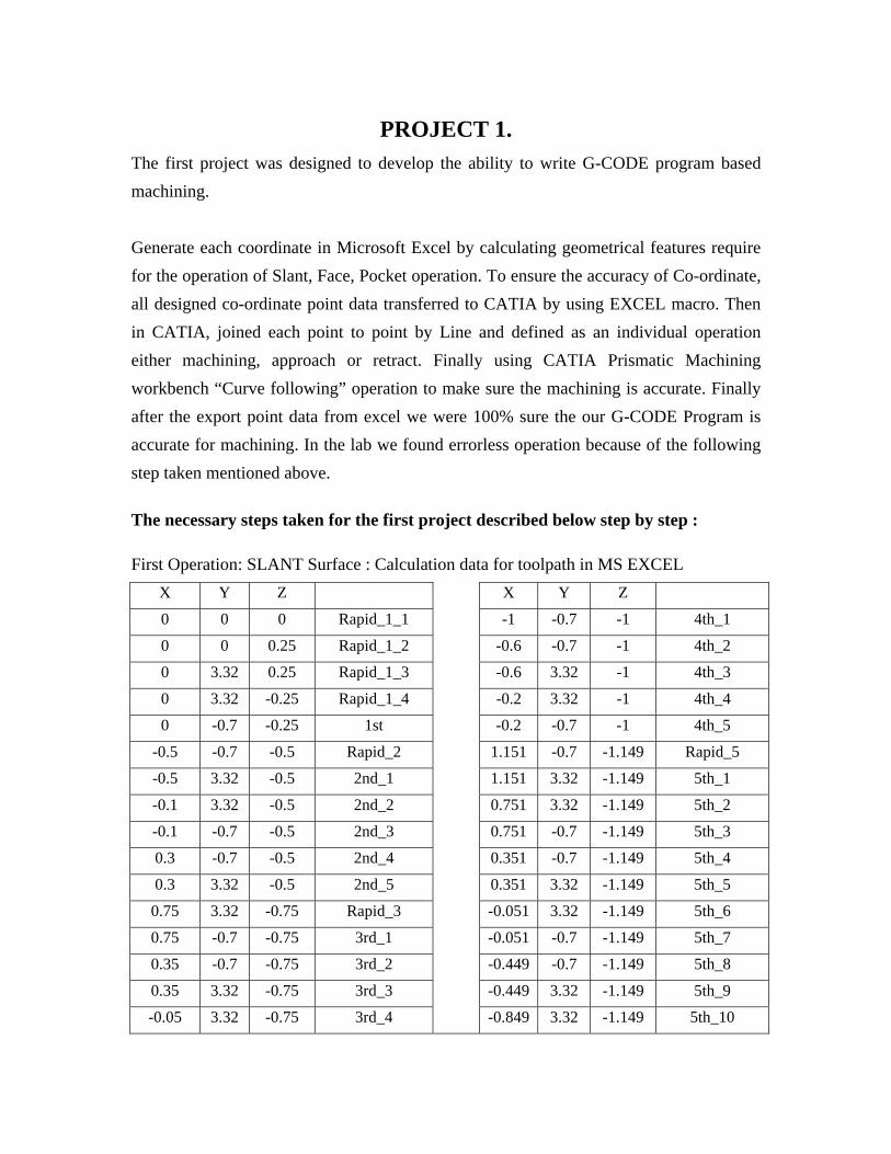
PROJECT 1. The first project was designed to develop the ability to write G-CODE program based machining. Generate each coordinate in Microsoft Excel by calculating geometrical features require for the operation of Slant, Face, Pocket operation. To ensure the accuracy of Co-ordinate, all designed co-ordinate point data transferred to CATIA by using EXCEL macro. Then in CATIA, joined each point to point by Line and defined as an individual operation either machining, approach or retract. Finally using CATIA Prismatic Machining workbench “Curve following” operation to make sure the machining is accurate. Finally after the export point data from excel we were 100% sure the our G-CODE Program is accurate for machining. In the lab we found errorless operation because of the following step taken mentioned above.
The necessary steps taken for the first project described below step by step :
First Operation: SLANT Surface : Calculation data for toolpath in MS EXCEL X Y Z X Y Z
0 0 0 Rapid_1_1 -1 -0.7 -1 4th_1
0 0 0.25 Rapid_1_2 -0.6 -0.7 -1 4th_2
0 3.32 0.25 Rapid_1_3 -0.6 3.32 -1 4th_3
0 3.32 -0.25 Rapid_1_4 -0.2 3.32 -1 4th_4
0 -0.7 -0.25 1st -0.2 -0.7 -1 4th_5
-0.5 -0.7 -0.5 Rapid_2 1.151 -0.7 -1.149 Rapid_5
-0.5 3.32 -0.5 2nd_1 1.151 3.32 -1.149 5th_1
-0.1 3.32 -0.5 2nd_2 0.751 3.32 -1.149 5th_2
-0.1 -0.7 -0.5 2nd_3 0.751 -0.7 -1.149 5th_3
0.3 -0.7 -0.5 2nd_4 0.351 -0.7 -1.149 5th_4
0.3 3.32 -0.5 2nd_5 0.351 3.32 -1.149 5th_5
0.75 3.32 -0.75 Rapid_3 -0.051 3.32 -1.149 5th_6
0.75 -0.7 -0.75 3rd_1 -0.051 -0.7 -1.149 5th_7
0.35 -0.7 -0.75 3rd_2 -0.449 -0.7 -1.149 5th_8
0.35 3.32 -0.75 3rd_3 -0.449 3.32 -1.149 5th_9
-0.05 3.32 -0.75 3rd_4 -0.849 3.32 -1.149 5th_10

Final Operation : Face, Pocket, Drill StartLoft Point Name
StartCurve X Y Z
EXCEL MACRO
0 0 0 Rapid_1_1
0 0 0.25 Rapid_1_2
0 3.32 0.25 Rapid_1_3
0 3.32 -0.25 Rapid_1_4
0 -0.7 -0.25 1st
-0.5 -0.7 -0.5 Rapid_2
-0.5 3.32 -0.5 2nd_1
-0.1 3.32 -0.5 2nd_2
-0.1 -0.7 -0.5 2nd_3
0.3 -0.7 -0.5 2nd_4
0.75 3.32 -0.75 Rapid_3
0.75 -0.7 -0.75 3rd_1
0.35 -0.7 -0.75 3rd_2
0.35 3.32 -0.75 3rd_3
-0.05 3.32 -0.75 3rd_4
-1 3.32 -1 Rapid_4
-1 -0.7 -1 4th_1
-0.6 -0.7 -1 4th_2
-0.6 3.32 -1 4th_3
-0.2 3.32 -1 4th_4
-0.2 -0.7 -1 4th_5
1.151 -0.7 -1.149 Rapid_5
1.151 3.32 -1.149 5th_1
0.751 3.32 -1.149 5th_2
0.751 -0.7 -1.149 5th_3
0.351 -0.7 -1.149 5th_4
0.351 3.32 -1.149 5th_5
-0.051 3.32 -1.149 5th_6
-0.051 -0.7 -1.149 5th_7
-0.449 -0.7 -1.149 5th_8
EndLoft
EndCurve
End

SLANT surface Curve Following tool path Data imported from MS EXCEL
Final Product After Machining

FACING and POCKETING tool path Data imported from MS EXCEL
Pocketing Operation Machining Picture.

DRILLING
G-CODE for SLANT SURFACE %PM N1001 ;SLANT SURFACE MACHINING ;DATE: MARCH 24,2008 ;PROGRAM BY Maruf Khondker, Shaiful Islam N10 G00 G17 G40 G44 G70 G80 G90 N15 T1 M66 ; 1" END-MILL MANUAL TOOL CHANGE N20 G54 N25 G00 G90 X0 Y0 Z0.25 S2000 M03 ;RAPID N30 Y3.32 N35 Z-0.25 N40 G01 X0 Y-0.7 Z-0.25 F9.0 M08 ;MACHINING 1 N45 G00 X-0.5 Y-0.7 Z-0.5 ;RAPID N50 G01 X-0.5 Y3.32 Z-0.5 F9.0 ;MACHINING 2 N55 X-0.1 N60 Y-0.7 N65 X0.3 N70 Y3.32 N75 G00 X0.75 Y3.32 Z-0.75 ;RAPID

N80 G01 X0.75 Y-0.7 Z-0.75 F9.0 ;MACHINING 3 N85 X0.35 N90 Y3.32 N95 X-0.05 N100 Y-0.7 N105 X-0.45 N110 Y3.32 N115 G00 X-1 Y3.32 Z-1 ;RAPID N120 G01 X-1 Y-0.7 Z-1 F9.0 ;MACHINING 4 N125 X-0.6 N130 Y3.32 N135 X-0.2 N140 Y-0.7 N145 X0.2 N150 Y3.32 N155 X0.6 N160 Y-0.7 N165 G00 X1.151 Y-0.7 Z-1.149 ;RAPID N170 G01 X1.151 Y3.32 Z-1.149 F9.0 ;MACHINING 5 N175 X0.751 N180 Y-0.7 N185 X0.351 N190 Y3.32 N195 X-0.051 N200 Y-0.7 N205 X-0.449 N210 Y3.32 N215 X-0.849 N220 Y-0.7 N225 X-1.149 N230 Y3.32 N235 G00 X-1.149 Y3.32 Z0.25 M09 ;RAPID, COOLANT OFF N240 M05 ;SPINDLE STOP N245 G53 Z0 :Machine Home Z N250 G53 X0 Y0 ;MACHINE HOME X Y N255 M30 ;PROGRAMME STOP

G-CODE for FACE, POCKET, DRILL %PM N2008 ; FACE, POCKET, DRILL MACHINING ;DATE: MARCH 24,2008 ;PROGRAM BY Maruf Khondker, Shaiful Islam N01 G00 G17 G40 G44 G70 G80 G90 N02 T1 M66 ; 1" END-MILL N03 G54 N04 G00 X0 Y0 Z1 S2000 M03 N05 X-0.7 Y0 N10 Z-0.125 N35 G01 X2.625 Y0 Z-0.125 F9 M8 N40 Y-0.5 N45 X-0.25 N45 Y-1 N50 X2.625 N55 Y-1.5 N60 X-0.25 N65 Y-2 N70 X2.625 N71 Y-2.5 N72 X-0.25 N73 G00 X-0.25 Y-2.5 Z1 ;RAPID2_1 N74 X3.45 Y-2.62 ;RAPID2_2 N75 Z-0.375 ;RAPID2_3 N76 G01 X0 Y-2.62 Z-0.375 F9 ;POCKET1_1 N77 G00 X0 Y-2.62 Z1 ;RAPID3_1 N78 X3.45 Y-2.21 ;RAPID3_2 N79 Z-0.375 ;RAPID3_3 N80 G01 X0 Y-2.21 Z-0.375 F9 ;POCKET1_2 N85 G00 X0 Y-2.21 Z1 ;RAPID3_1 N90 X3.45 Y-1.71 ;RAPID3_2 N95 X3.45 Y-1.71 Z-0.375 ;RAPID3_3 N100 G01 X0 Y-1.71 Z-0.375 F9 ;POCKET1_3 N105 G00 X0 Y-1.71 Z1 ;RAPID4_1 N110 X3.45 Y-1.38 ;RAPID4_2 N115 Z-0.375 ;RAPID4_3 N120 G01 X-.2 Y-1.38 Z-0.375 F9 ;POCKET1_4 N125 G00 X-.2 Y-1.38 Z1 ;RAPID2_1

N130 X3.7 Y-2.62 ;RAPID2_2 N135 Z-0.625 ;RAPID2_3 N140 G01 X0 Y-2.62 Z-0.625 F9 ;POCKET2_1 N145 G00 X0 Y-2.62 Z1 ;RAPID3_1 N150 X3.7 Y-2.21 ;RAPID3_2 N155 Z-0.625 ;RAPID3_3 N160 G01 X0 Y-2.21 Z-0.625 F9 ;POCKET2_2 N165 G00 X0 Y-2.21 Z1 ;RAPID3_1 N170 X3.7 Y-1.71 ;RAPID3_2 N175 Z-0.625 ;RAPID3_3 N180 G01 X0 Y-1.71 Z-0.625 F9 ;POCKET2_3 N185 G00 X0 Y-1.71 Z1 ;RAPID4_1 N190 X3.7 Y-1.38 ;RAPID4_2 N195 Z-0.625 ;RAPID4_3 N200 G01 X-.2 Y-1.38 Z-0.625 F9 ;POCKET2_4 N205 G00 X-.2 Y-1.38 Z1 ;RAPID2_1 N210 X3.95 Y-2.62 ;RAPID2_2 N215 Z-0.875 ;RAPID2_3 N220 G01 X0 Y-2.62 Z-0.875 F9 ;POCKET3_1 N225 G00 X0 Y-2.62 Z1 ;RAPID3_1 N230 X3.95 Y-2.21 ;RAPID3_2 N235 Z-0.875 ;RAPID3_3 N240 G01 X0 Y-2.21 Z-0.875 F9 ;POCKET3_2 N245 G00 X0 Y-2.21 Z1 ;RAPID3_1 N250 X3.95 Y-1.71 ;RAPID3_2 N255 Z-0.875 ;RAPID3_3 N260 G01 X0 Y-1.71 Z-0.875 F9 ;POCKET3_3 N265 G00 X0 Y-1.71 Z1 ;RAPID4_1 N270 X3.95 Y-1.38 ;RAPID4_2 N275 Z-0.875 ;RAPID4_3 N280 G01 X-.2 Y-1.38 Z-0.875 F9 ;POCKET3_4 N285 G00 X-.2 Y-1.38 Z1 ;RAPID2_1 N290 X4.075 Y-2.62 ;RAPID2_2 N295 Z-1 ;RAPID2_3 N300 G01 X0 Y-2.62 Z-1 F9 ;POCKET4_1 N305 G00 X0 Y-2.62 Z1 ;RAPID3_1 N310 X4.075 Y-2.21 ;RAPID3_2 N315 Z-1 ;RAPID3_3 N320 G01 X0 Y-2.21 Z-1 F9 ;POCKET4_2

N325 G00 X0 Y-2.21 Z1 ;RAPID3_1 N330 X4.075 Y-1.71 ;RAPID3_2 N335 Z-1 ;RAPID3_3 N340 G01 X0 Y-1.71 Z-1 F9 ;POCKET4_3 N345 G00 X0 Y-1.71 Z1 ;RAPID4_1 N350 X4.075 Y-1.38 ;RAPID4_2 N355 Z-1 ;RAPID4_3 N360 G01 X-.2 Y-1.38 Z-1 F9 ;POCKET4_4 N365 G00 X-.2 Y-1.38 Z10 ;RAPID4_1 N366 X0 Y0 N367 G40 ;CANCEL TR N370 M9 ;COOLANT OFF N375 M5 ;SPINDLE OFF N376 T2 M66 ;SPOT DRILL N379 G00 Z1 S500 M03 ;1/2 INCH N380 X0.75 Y-1.74 N381 Z0 M08 N382 G43 N383 G81 G99 X0.75 Y-1.74 Z-0.5 I-1.125 F4 N384 G98 X2.25 N385 G80 N386 G00 Z10 N387 M5 M9 N388 T3 M66 ;0.69" DRILL N389 G00 z1 S500 M03 ;DRILL CYCLE N390 X0.75 Y-1.74 N395 Z0 M08 N405 G81 G99 X0.75 Y-1.74 Z-0.5 I-2 F4 N410 G98 X2.25 N415 G80 G44 N420 G00 Z1 M09 M05 ; RAPID N435 G53 Z0 ; MACHINE HOME z N440 G53 X0 Y0 ; MACHINE HOME x y N450 M30 ; PROGRAMME STOP

Design and Optimization of Model Main Pad
Main Body Sketch of Engine Side Cover, All Geometry is fully Constrained and only 10 operation used to design the entire part. Outer Fillet diameter 0.5 inch and constrained. Design is such way so that it’s possible to change without unsettling others component.

Apart from operation the whole part has design flexibility, and necessary component are related to independent to each other.
Pocket (top housing of Engine side cover) Top Housing of engine side cover sketch design is also fully constrained geometry and capable of design flexibility.

Surface for Isoperimetric operation
Surface to Thickness
Top Housing Shaft Mounting Pocket.

Bottom Housing for slave rotor of engine side cover.

Roughing Both side using 2-1-1/4 inch cutter.

Defining approach retract and machining according to the requirement. Almost all the cases Approach and retract defined from safety plane. Some cases like in this figure Tangential entry to workpiece used which is very essential for good machining and don’t make damage to workpiece and as well as increase the tool life. Normally after tangential entry 1 inch is enough for machining but for big tool like 2-1/4 inch, safety reason 2 inch machining tangential entry used in the project.

Used manual roughing for whole workpiece to save machining time. In industry most of the cases engineers design custom roughing rather than using CATIA default roughing operation. Because CATIA default roughing operation uses lot of unnecessary uses of toolpath which significantly increase the machining time.
Top housing Major two pocket Machining toolpath, depth of cut and feed rate used from table specified by Material Standard Data sheet, HSS tool requirement.

Outer Profile Roughing and Side semi finish of pocket.
Mid surface Roughing using 2-1/4 inch flat end mill. Bottom housing grove pocket using 1/2” Ball nose end Mill.

Finishing of Surface using ½” ball nose. In industry 0.001 to 0.0001 inch scallop height used. But for the project because of time constrained and availability of machine only 0.05 scallop height used. Profile contouring use to make a monogram name “CU” Mean Concordia university. Only 0.05 inch machining used which is enough to make CU sign on the surface.

Drilling of 7 Hole ¼ inch drill bit tool used and depth of cut is 1”.


Third Wave AdvantEdge™ Analysis Software The Software Thirdwave is very user friendly and capable to do analysis accurately and conveniently. Lot of analysis Cutting force, Milling drilling tool deflection time history in Tecplot Rotating workpiece for rotating tool simulations in Tecplot, tool deflection with beam model, Heat Transfer, 3 Strain Hardening, Thermal Softening, Elasticity, Damage Prediction, Conductivity, Thermal Expansion etc. Also possible using Third Wave. But in this project the student version of this software is unable to produce all the analysis result mentioned above. The basic sample output attach herewith.
Third Wave AdvantEdge™ Benefits Third Wave AdvantEdge™ is a powerful tool for engineers; to design, setup, improve and optimize machining processes. It enables us to determine machining parameters and tooling configurations that can reduce cutting forces, temperatures, and part distortion, all offline. This reduces the need for online testing, which costs money and valuable production time. The direct benefits of Third Wave AdvantEdge™ include:
• Reduce expensive cutting tests
• Prolong tool life and reduce tool breakage
• Improve tool geometries and chip control
• Machine more quickly
• Produce more efficiently
• Reduce part distortion due to heat generation, cutting forces, residual stress, etc.
• Increase material removal rates
• Increase machine utilization
Third Wave AdvantEdge™ components.
• Simulation
• Setup
• AdvantEdgeTM
• Engine
• Results

The Opertaion for the Project Select Custom Workpice. For analysis small dimension do the faster Proceesing time for rapid simulation mode.
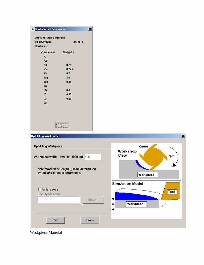
Wrokpiece Material

Here material was selected the same material supplied for the final Project. However Third Wave is capable to analysis the all available material for CNC Machining.

The Cutting edge radius is 1mm only since the workpiece is very small in size for analysis; therefore according to the workpiece and tool cutting edge ratio 0.1 mm is enough for analysis.

Here tool material was also elected the same material of tool supplied for the final Project. However Third Wave is capable to analysis the all available tool for CNC Machining. Necessary Process Parameter feed, depth of cut and Cutting speed data input taken from the data of the Final Project Car Engine Side Cover. Intial temperature data taken as room temperature 20o C
Since the workpiece is small in size for simulation analysis therefore; the processing time for up milling operation was significantly less than analysis of a regular or larger workpiece operation.

FOR ¼ INCH BALL NOSE END MILL
TOOL Material

Milling Parameter for Work piece and Tool.
One of Sample Result
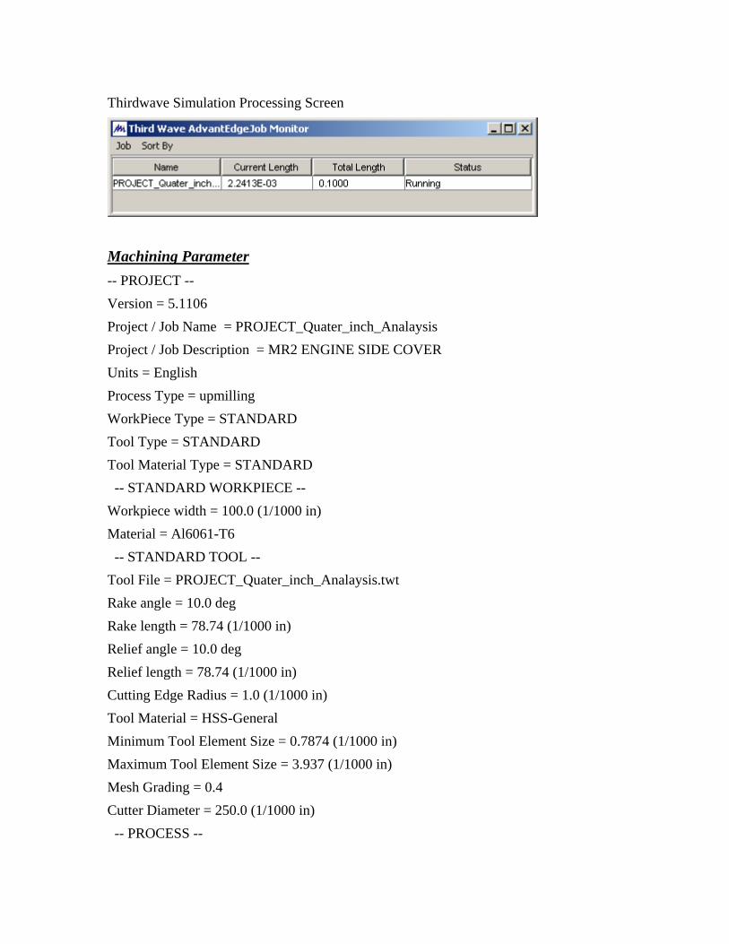
Thirdwave Simulation Processing Screen
Machining Parameter -- PROJECT -- Version = 5.1106 Project / Job Name = PROJECT_Quater_inch_Analaysis Project / Job Description = MR2 ENGINE SIDE COVER Units = English Process Type = upmilling WorkPiece Type = STANDARD Tool Type = STANDARD Tool Material Type = STANDARD -- STANDARD WORKPIECE -- Workpiece width = 100.0 (1/1000 in) Material = Al6061-T6 -- STANDARD TOOL -- Tool File = PROJECT_Quater_inch_Analaysis.twt Rake angle = 10.0 deg Rake length = 78.74 (1/1000 in) Relief angle = 10.0 deg Relief length = 78.74 (1/1000 in) Cutting Edge Radius = 1.0 (1/1000 in) Tool Material = HSS-General Minimum Tool Element Size = 0.7874 (1/1000 in) Maximum Tool Element Size = 3.937 (1/1000 in) Mesh Grading = 0.4 Cutter Diameter = 250.0 (1/1000 in) -- PROCESS --

Radial width of cut = 125.0 (1/1000 in) Axial depth of cut = 25.0 (1/1000 in) Length of cut = 100.0 (1/1000 in) Feed per tooth = 5.0 (1/1000 in) Spindle speed = 2000.0 RPM Initial temperature = 68.0 degF Friction coefficient = Default Cutting mode = General External Coolant = OFF -- SIMULATION -- Simulation Mode = Rapid Steady State Analysis = 0 Avg. Length of Cut Ratio = 10.0 Chip Breakage = 0 Max. number of nodes = 12000 Max Element Size = 3.937 (1/1000 in) Min Element Size = 0.7874 (1/1000 in) Fraction of Radius = 0.6 Fraction of Feed = 0.1 Mesh Refine = 2 Mesh Coarse = 6 Output Frame = 30 Number of Threads = 1
Summary : After using Thirdwave software we learn the followings things that the software is capable to do the analysis of Chip characterization, Cutting and transverse tool forces, Tool/workpiece temperatures, heat generation rate, Plastic strain and strain rate, Von Mises, pressure and maximum shear stresses, Stress components, Velocity components and magnitude. It’s also open for further more analysis - data import from another popular software like CATIA, Nastran Patran and Ansys. As a CNC engineer new Thirdwave Software is a essential tool for Analysis and research.

G-CODE (Part of Full G-CODE)
%PM N2008 ; FINAL PROJECT, CAR Engine Side Cover ;DATE:APRIL 28, 2008
% N1 G90 N2 G17 G54 N3 T1 M6 N4 S1500 M3 N5 G00 X.2265 Y-1.3578 N6 G43 Z1 H1 N7 Z-.3 N8 G01 Z-.5 F10 N9 X-.55 Y1.54 N10 Y2.46 N11 X.2265 Y5.3578 N12 G00 Z1 N13 Y-1.3578 N14 Z-.8 N15 G01 Z-1 N16 X-.55 Y1.54 N17 Y2.46 N18 X.2265 Y5.3578 N19 G00 Z1 N20 S1500 M3 N21 X7.3729 Y5.3132 N22 Z-.3 N23 G01 Z-.5 N24 X8.3 Y2.46 N25 Y1.54 N26 X7.3729 Y-1.3132 N27 G00 Z1 N28 Y5.3132 N29 Z-.8 N30 G01 Z-1 N31 X8.3 Y2.46 N32 Y1.54 N33 X7.3729 Y-1.3132
N35 M5 N36 G17 G40 G49 G80 N37 T2 M6 N38 S1500 M3 N39 G00 X3.8268 Y4.2238 N40 G43 Z1 H2 N41 Z.075 N42 G01 Z-.125 F6 N43 Y2.2238 N44 X3.0768 N45 X2.5863 N46 X2.4349 Y2.224 N47 G03 X2.4349 Y1.776 R.4188 N48 G01 X2.5863 Y1.7762 N49 X3.0768 N50 X3.8268 N51 Y.6762 N52 G00 Z1 N53 Y3.8238 N54 Z.075 N55 G01 Z-.125 N56 Y2.7238 N57 X3.0768 N58 X2.5863 N59 X2.462 Y2.7367 N60 X2.3745 Y2.7204 N61 X2.1849 Y2.6571 N62 X2.0124 Y2.4914 N63 G03 X2.0124 Y1.5086 R.9188 N64 G01 X2.1509 Y1.3644 N65 X2.3745 Y1.2796 N66 X2.4822 Y1.2646 N67 X2.5862 Y1.2728 N68 X3.0768 Y1.2762 N69 X3.8268 N70 Y.2762 N71 X4.4768 N72 Y4.0262 F20

N74 S1500 M3 N75 G00 X4.0508 Y5.0112 N76 Z-.076 N77 G01 Z-.276 F6 N78 X3.9204 Y4.2726 N79 X3.7985 Y3.5819 N80 X3.8011 Y3.2402 N81 X3.9658 Y2.8613 N82 G02 X3.9658 Y1.1387 R1.46 N83 G03 X3.7985 Y.4181 R.9436 N84 G01 X3.9249 Y-.2979 N85 X4.0987 Y-1.2827 N86 G00 Z-.076 N87 X3.8539 Y5.0459 N88 G01 Z-.276 N89 X3.7235 Y4.3074 N90 X3.6016 Y3.6167 N91 X3.6029 Y3.2117 N92 X3.8043 Y2.7433 N93 G02 X3.8043 Y1.2567 R1.26 N94 G03 X3.6016 Y.3833 R1.1436 N95 G01 X3.728 Y-.3327 N96 X3.9018 Y-1.3174 N97 S1500 M3 N98 G00 Z1 N99 X4.3676 Y-.8831 N100 Z-.046 N101 G01 Z-.246 N102 X4.3688 Y-.7831 N103 X4.3811 Y.2495 N104 Y3.7505 N105 X4.3688 Y4.7831 N106 G00 Z1 N107 S1500 M3 N108 X2.4286 Y2.8032 N109 Z.183 N110 G01 Z.083 N111 Z-.167 N112 G03 X1.949 Y2.5315 R.5923
N113 X1.949 Y1.4685 R.9939 N114 X2.4314 Y1.1964 R.5912 N115 G02 X2.7252 Y2 R.9448 N116 X2.4312 Y2.7999 R.9592 N117 G00 Z1 N118 X2.4286 Y2.8032 N119 Z.017 N120 G01 Z-.083 N121 Z-.333 F20 N122 G03 X1.949 Y2.5315 R.5923 F6 N123 X1.949 Y1.4685 R.9939 N124 X2.4314 Y1.1964 R.5912 N125 G02 X2.7252 Y2 R.9448 N126 X2.4312 Y2.7999 R.9592 N127 G00 Z1 N128 X2.4286 Y2.8032 N129 Z-.15 N130 G01 Z-.25 N131 Z-.5 F20 N132 G03 X1.949 Y2.5315 R.5923 F6 N133 X1.949 Y1.4685 R.9939 N134 X2.4314 Y1.1964 R.5912 N135 G02 X2.7252 Y2 R.9448 N136 X2.4312 Y2.7999 R.9592 N137 G00 Z1 N138 S1500 M3 N139 X4.15 Y1.075 N140 Z.075 N141 G01 Z-.125 N142 X4.25 N143 X5 N144 X5.2152 N145 X5.2765 Y1.2313 N146 X5 Y1.275 N147 X4.25 N148 G00 Z1 N149 S1500 M3 N150 X4.15 Y2.725 N151 Z.075

N260 G01 X3.6047 Y4.4108 N261 G02 X4.5434 Y4.2956 R.77 N262 G01 X5.2387 Y4.27 N263 X5.75 N264 G02 X6.52 Y3.5 R.77 N265 G01 X6.5228 Y3.4273 N266 G02 X6.5228 Y.5727 R1.52 N267 G01 X6.7728 Y.5733 N268 G00 Z1 N269 X7.02 Y.5688 N270 Z-.95 N271 G01 Z-1 N272 X6.52 N273 Y.5 N274 X6.4791 Y.2525 N275 G02 X5.75 Y-.27 R.77 N276 G01 X5.2387 N277 X4.5434 Y-.2956 N278 G02 X3.6047 Y-.4108 R.77 N279 G01 X3.6069 Y-.4115 N280 G02 X2.8023 Y-.52 R4.7709 N281 X1.6278 Y-.1982 R2.27 N282 G01 X1.6245 Y-.1997 N283 G02 X.7601 Y.7431 R.77 N284 G01 X.7579 Y.7442 N285 G02 X.5446 Y1.3789 R2.6653 N286 G01 X.5442 Y1.3794 N287 G02 X.5442 Y2.6206 R.77 N288 G01 X.5446 Y2.6211 N289 G02 X.7579 Y3.2558 R2.6653 N290 G01 X.7601 Y3.2569 N291 G02 X1.6315 Y4.1986 R.77 N292 G01 X1.9713 Y4.3661 N293 X2.2281 Y4.4486 N294 X2.4173 Y4.4887 N295 G02 X3.1871 Y4.4855 R2.27 N296 G01 X3.6047 Y4.4108
N297 G02 X4.5434 Y4.2956 R.77 N298 G01 X5.2387 Y4.27 N299 X5.75 N300 G02 X6.52 Y3.5 R.77 N301 G01 X6.5228 Y3.4273 N302 G02 X6.5228 Y.5727 R1.52 N303 G01 X6.7728 Y.5733 N304 G00 Z1 N305 M5 N306 G17 G40 G49 G80 N307 T3 M6 N308 S2000 M3 N309 G00 X1.9251 Y1.9748 N310 G43 Z1 H3 N311 Z-.11 N312 G01 Z-.21 F8 N313 X1.9279 Y1.825 Z-.223 N314 X1.5757 Z-.254 N315 X1.5697 Y2.175 Z-.285 N316 X1.9279 Z-.316 N317 X1.9251 Y1.9748 Z-.333 N318 X1.9279 Y1.825 N319 X1.5757 N320 X1.5697 Y2.175 N321 X1.9279 N322 X1.9251 Y1.9748 N323 Z1 F20 N324 G00 Z-.318 N325 G01 Z-.418 F8 N326 X1.9279 Y1.825 Z-.431 N327 X1.5757 Z-.462 N328 X1.5697 Y2.175 Z-.493 N329 G00 X-1.149 Y3.32 Z0.25 N330 M9 M5 ;Collant and Spindle offN335 G53 Z0 :Machine Home Z N340 G53 X0 Y0 ;MACHINE HOME X Y N350 M30 ;MACHINE stop program end

ACHIEVEMENT: Course content and the project is very related and synchronies with each other. We were learning each step in class and applying at the same time. This project helps us understanding the course materials. We face a lot of challenge during the project work. Starting from the G-CODE to final machining. We were the first group for both Project, therefore; we faced lot of unwanted difficulty because of machine and machine parameter. We overcome the problems and difficulties that we faced in the lab due to some features of machines are unavailable and need to upgrade. We spent lot of time to find the alternative solution to solve the problem. Finally we become successful. As a result professional machining has been made. The course is practical oriented therefore; we had a chance to apply the content with different problem solving example which increase our analytical ability that will prepare us for the competitive job market.

CONCLUSION Computer Numerically Controlled (CNC) Machining Manufacturing process of the Engine side cover done using 3-AXIS CNC Machine. After manufacture, the part quality appears to satisfy the industry standard and surface quality seems to be good enough with accuracy. The following factors have significant influence on the quality of the final part-
• Proper Design of part using CATIA
• Proper selection of tool with respect to Workpiece material.
• Optimum Design of Part so that change and rearrange is possible according to the requirement of machine in final step.
• Proper selection of cutting force includes depth of cut, feed rate etc.
• Ensuring proper selection of toll and no reparation of tool if possible.
• Optimum design of toolpath.
• Before defining Major machining parameter like depth of cut, feed rate software analysis tool (Ex - ThirdWave) should used to determine the best selection of machining parameter.

REFERENCES
[1] Class Note of CNC MECH 6611, Winter, 2007, Concordia University . [2] http://en.wikipedia.org/wiki/CNC [3] http://www.cnczone.com/ [4] Fagor Controller Programming Manual. [5] Deckel Maho CNC Machine Programming Manual. [6] B. L. Juneja & G.S. Sekhon, Fundamentals of Metal Cutting and Machine
Tools, Wiley Eastern Limited, [7] Robert I. King, Handbook of High-speed Machining Technology, Chapman
and Hall, 1985. [8] Fred H. Colvin & Frank A. Stanley, Drilling and Surfacing Practice, Mc
Graw-Hill Book company, INC, [9] D. Brian K. Lambert, Milling Methods and Machines-First Edition, Society
of Manufacturing Engineers, Michigan, 1982. [10] CATIA V5 Help.


