Application Note Fagor Electrónica Semiconductores www.fagorelectronica.com For technical questions please contact: Version: Jul-12 Document Name: Ultversofrecdioforhig [email protected]Page Number: : 1/7 Fagor Electrónica Ultrafast Soft Recovery Diodes for High Speed Switching Applications Abstract Fagor Electrónica has developed a new series of ultrafast soft recovery diodes to meet the requirements of high frequency operation and power ratings. The best trade-off for leakage current, forward voltage drop (static parameters) and reverse recovery (dynamic parameter) have been achieved, with a typical recovery time as low as 15-20nsg. Fagor Electrónica FESx(D,G,J)ySR series reduce losses in the circuit minimizing the Electromagnetic Interferences. SERIES NAME PRODUCT RANGE Peak Reverse Voltage VRM [V] Output Current [A] trr [nsg] FESxDySR 200 1 ~ 3 < 25 FESxGySR 400 1 ~ 3 < 25 FESxJySR 600 1 ~ 3 < 50 Introduction Ultrafast recovery rectifiers are nowadays playing a key role for high frequency applications where a fast and rugged switching performance is required. They are demanded as freewheeling and snubber components in most electronic circuits. In order to reduce overall losses in the circuit and to prevent any failure mechanisms that might occur during the diode switching transients the most important features required for fast recovery diodes are: 1. - Low on-state voltage. 2. - Low leakage current. 3. - Low reverse recovery losses. 4. - Low noise.
Fagor Electrónica Ultrafast Soft Recovery Diodes fo r High
Speed Switching Applications
Abstract Fagor Electrónica has developed a new series of ultrafast soft recovery diodes to meet the requirements of high frequency operation and power ratings. The best trade-off for leakage current, forward voltage drop (static parameters) and reverse recovery (dynamic parameter) have been achieved, with a typical recovery time as low as 15-20nsg. Fagor Electrónica FESx(D,G,J)ySR series reduce losses in the circuit minimizing the Electromagnetic Interferences. SERIES NAME PRODUCT RANGE
Introduction Ultrafast recovery rectifiers are nowadays playing a key role for high frequency applications where a fast and rugged switching performance is required. They are demanded as freewheeling and snubber components in most electronic circuits. In order to reduce overall losses in the circuit and to prevent any failure mechanisms that might occur during the diode switching transients the most important features required for fast recovery diodes are: 1. - Low on-state voltage. 2. - Low leakage current. 3. - Low reverse recovery losses. 4. - Low noise.
During the transition from the conduction state to the blocking state (turn-ON to turn-OFF) the current drops from IF (Forward Current) to IR ≈ Zero (Reverse Current). A change in the current polarity takes place during this process. A reverse maximum value is reached (–IRM) (Fig.1). IF
Figure 1 Because of the existence of parasitic LC in different parts of the electronic circuit, the way the IRM to Zero current recovery occurs is responsible for Electromagnetic Interferences (EMI) generation. Feature of Fagor Electrónica Ultrafast Rectifier Di odes Fagor Electrónica Ultrafast Diodes (FESxySR series) are fabricated in a P+iN+ epitaxial structure with a top-glass junction termination (Fig.2).
Three are the design elements that play a major role in the control of the dynamic (switching) performance of the device: [1] Epitaxial layer thickness N-; [2] Base P concentration; [3] Life time killing control. During the transition from ON-STATE to OFF-STATE a finite time is required to remove the excess of carriers before the diode will be able to block the voltage. This time is proportional to the thickness of the N- region [1] and the presence of recombination centres that are created by adding uniform lifetime killers [3] . Fagor Electrónica (FESxySR series) ultrafast diodes adopts platinum diffusion as lifetime killers because it is well established that for equal forward characteristics, the leakage current of platinum doped devices are much lower than for the gold doped devices at any temperature. Fig. 3 shows the typical “IR variation vs. temperature” curve for a 2A/200V Fagor Electrónica ultrafast diode (FESxySR series).
IR vs. V B R
0
510
1520
25
3035
40
0 50 100 150 200 Volts.
nAm
ps. Tj = -55 ºC
Tj = +25 ºC
IR vs. V B R
0
2
4
6
8
10
12
14
0 50 100 150 200 Volts.
µAm
ps.
Tj = +175 ºC
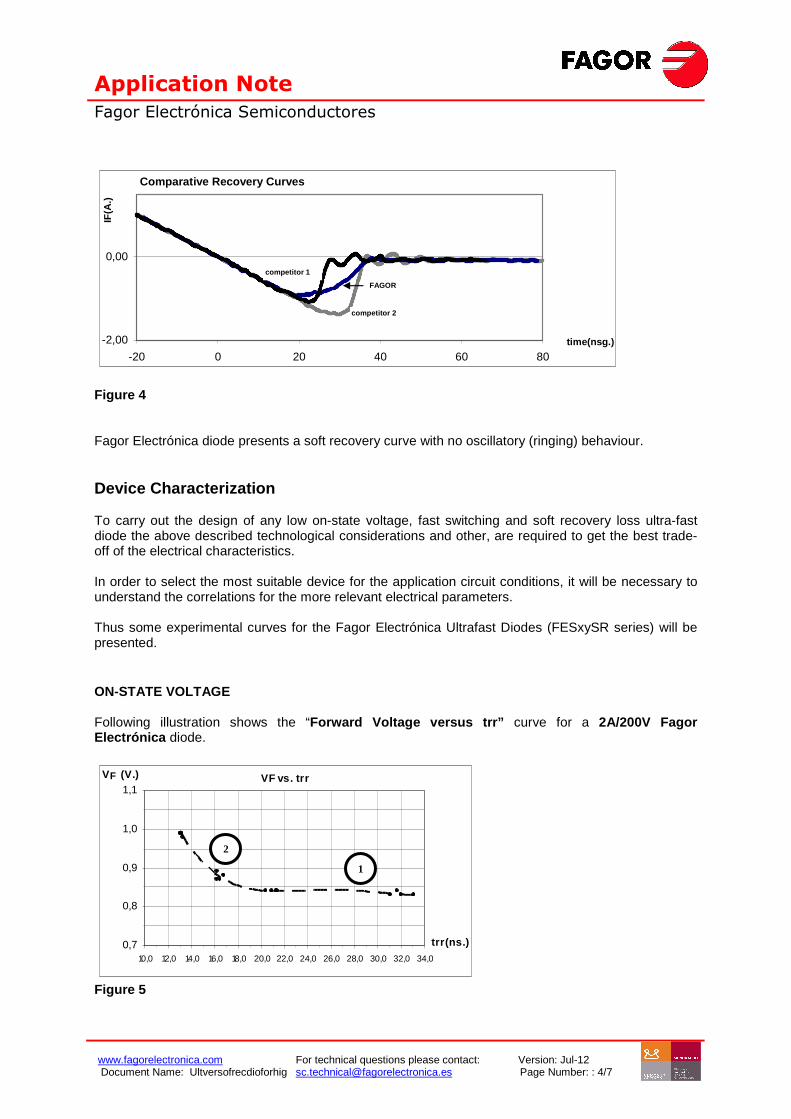
Figure 3 As long as the excess of carriers are at the end of the drift region, the PN- junction must be forward biased. Consequently the change in the voltage will be small from its conduction value (Fig.1). The shape and distribution of the stored charge in the drift region is a very important factor affecting the reverse recovery characteristics of the diode. For the control of the gradient for the excess carrier concentration the base P concentration [2] plays a major role. At the end of “ta” time all the carriers have been removed and the junction becomes reverse biased. At this point, the diode voltage goes negative which change is proportional to dI/dt. The current will now evolve from –IR to zero (“tb” time). If this dI/dt reverse recovery is large, the peak reverse VRM(REC) voltage is also high, causing failures when exceeding the blocking voltage capability. When the slope of the recovery is very fast or it shows a final ringing, noise immunity problems will be generated because of the emission of radio frequency. Once the carriers have been removed, the depletion layer expands into the drift region and thus the diode is able to block the reverse voltage. Fagor Electrónica Ultrafast Diodes (FESxySR series) have been developed integrating all the above exposed technological considerations. Figure 4 shows the reverse recovery current waveform for a 2A/200V Fagor Electrónica diode compared to other ultra-fast conventional diodes from competitors.
Figure 4 Fagor Electrónica diode presents a soft recovery curve with no oscillatory (ringing) behaviour. Device Characterization To carry out the design of any low on-state voltage, fast switching and soft recovery loss ultra-fast diode the above described technological considerations and other, are required to get the best trade-off of the electrical characteristics. In order to select the most suitable device for the application circuit conditions, it will be necessary to understand the correlations for the more relevant electrical parameters. Thus some experimental curves for the Fagor Electrónica Ultrafast Diodes (FESxySR series) will be presented. ON-STATE VOLTAGE Following illustration shows the “Forward Voltage versus trr” curve for a 2A/200V Fagor Electrónica diode.
As follows from the picture the “VF vs. trr” curve has two well established regimes. For high trr values (REGIME 1) the “VF vs. trr” relation is basically steady. As the trr value decreases it is reached a point where the “VF vs. trr” relation becomes exponential (REGIME 2); in such a way that the lower the trr the higher the VF. For the (2A/200V) Fagor Electrónica Ultrafast diode this regime change takes place at a trr = 19 nsg. REVERSE RECOVERY The Softness Factor (SF) is defined as tb/ta (fig. 1). It is useful to define de softness degree of any recovery curve: the higher its value the softer the reverse recovery curve. Following illustration shows experimental results for “Softness Factor versus trr”.
Figure 6 As the trr decreases the Softness Factor increases, indicating that the reverse recovery current will be softer. Figure 7 collects some reverse recovery current waveforms corresponding to the numbered points from experimental curve in figure 6.
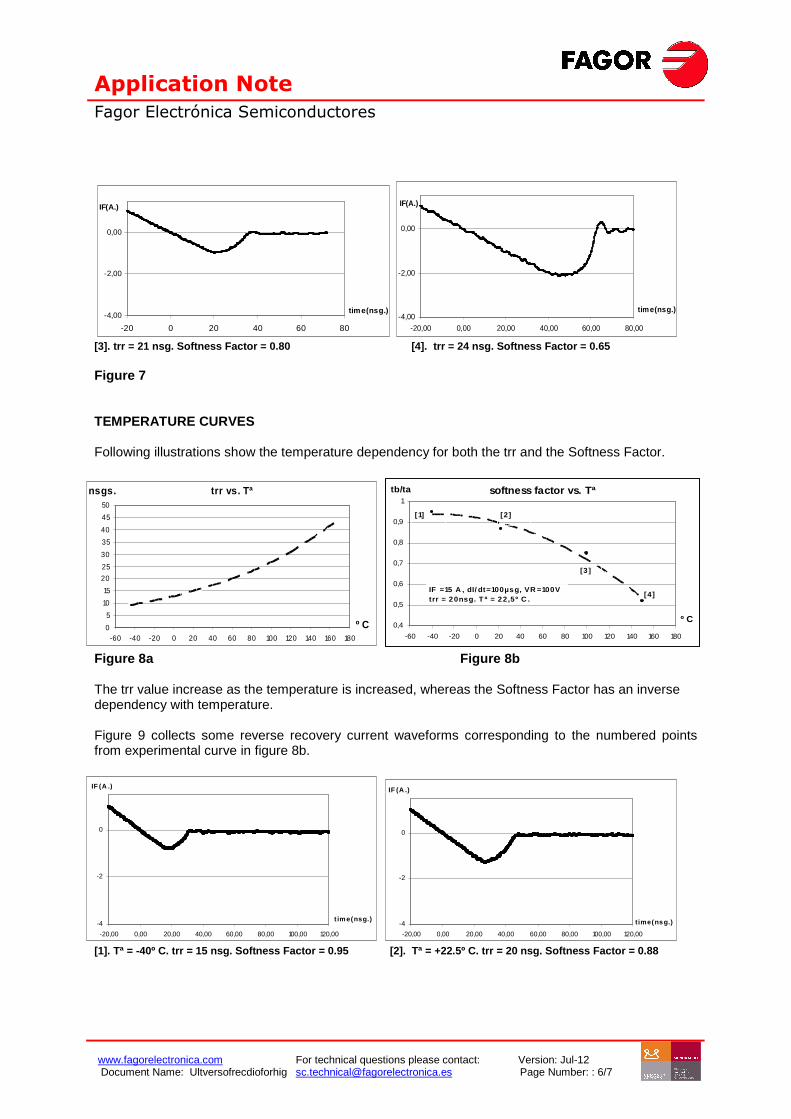
[3]. trr = 21 nsg. Softness Factor = 0.80 [4]. trr = 24 nsg. Softness Factor = 0.65 Figure 7 TEMPERATURE CURVES Following illustrations show the temperature dependency for both the trr and the Softness Factor.
trr vs. Tª
0
5
10
15
20
25
30
35
40
45
50
-60 -40 -20 0 20 40 60 80 100 120 140 160 180
º C
nsgs. softness factor vs. Tª
0,4
0,5
0,6
0,7
0,8
0,9
1
-60 -40 -20 0 20 40 60 80 100 120 140 160 180
º C
tb/ta
[2 ]
[3 ]
[4]
[1]
IF =15 A , dI/ dt=100µsg, VR =100Vtrr = 20nsg. T ª = 22,5º C .
Figure 8a Figure 8b The trr value increase as the temperature is increased, whereas the Softness Factor has an inverse dependency with temperature. Figure 9 collects some reverse recovery current waveforms corresponding to the numbered points from experimental curve in figure 8b.
[3]. Tª = +100º C. trr = 32 nsg. Softness Factor = 0.75 [4]. Tª = +150º C. trr = 44 nsg. S oftness Factor = 0.53 Figure 9 It is remarkable that Fagor Electrónica (FESxySR series) ultrafast diodes are free of oscillatory behaviour at any range of operation temperature as followed from graphs above. The forward voltage related to the temperature is graphed as follows (Figure 10).
0,4
0,5
0,6
0,7
0,8
0,9
1,0
1,1
1,2
1,3
1,4
0,1 1 10 100IF, FORWARD CURRENT(V)
VF
, FO
RW
AR
D V
OLT
AG
E (
V)
T j = 2 5ºC
T j = - 4 0 ºC
T j = 10 0 ºC
T j = 150 ºC
Figure 10 Conclusion Fagor Electrónica has introduced a new family of soft recovery ultrafast diodes in the range of 200V-400V. This paper outlines the main design elements that have been considered in the control of dynamic performance of the device. Some (VF, trr), (Softness Factor, trr) experimental curves have been presented being useful to get the best trade-off of the characteristics required for the device: low losses and low EMI for industrial application. Thus, Fagor Electrónica (FESxySR series) ultrafast diodes are able to offer the best trade-off for (trr / VF / Softness Factor ) in a band-gap of (15-20 nsg. /0.84-0.86 Volts / 0.90-1.50) showing high strength to all the application temperatures.