En`ineerin` Failure Analysis\ Vol[ 4\ No[ 2\ pp[ 194Ð107\ 0887 Þ 0887 Elsevier Science Ltd[ All rights reserved \ Pergamon Printed in Great Britain 0249Ð5296:87 ,08[99 ¦ 9[99 PII] S0249Ð5296"87#99907Ð0 FAILURE ANALYSIS OF A WELD REPAIRED STEAM TURBINE CASING S[ GHOSH CHOWDHURY\ N[ K[ MUKHOPADHYAY\ G[ DAS\ S[ K[ DAS and D[ K[ BHATTACHARYA Material Characterization Division\ National Metallurgical Laboratory\ Jamshedpur\ 720996\ India "Received 17 January 0887# Abstract *The present study was aimed at analysing the failure of a weld repaired turbine casing after 29 years of total service including 4 years after weld repair[ The casing was weld repaired by a high CrÐNi weld metal "13CrÐ21NiÐ3MnÐFe#[ The base metal\ a low alloy ferritic steel "0CrÐ9[4 Mo steel# with ferriteÐpearlite structure did not show any abnormality to indicate signi_cant degradation[ Fracture surface showed voids and microcracks[ The cracks might have initiated from the voids present in the weld region possibly by thermal fatigue mechanism[ The high level of thermal stress appears to be operative due to thicker section of the casing and also due to high mismatch of thermal expansion coe.cients of the base metal and the weld metal[ Dilution of alloying elements took place and d!ferrite was observed at the grain boundaries as predicted by the Schae/er diagram[ The d!ferrite was transformed to s!phase and alloy carbides during high temperature service "499>C#[ The propagation of cracks generated by thermal fatigue was facilitated by the formation of embrittled s!phase at the austenite grain boundary and this ultimately led to an early failure of the casing[ Þ 0887 Elsevier Science Ltd[ All rights reserved[ Keywords] Power!plant failure\ weld\ heat!a}ected zone\ thermal fatigue\ embrittlement[ 0[ INTRODUCTION The e.ciency of a power plant depends on the performance of various components operating under wide range of conditions[ Therefore\ the design of a particular component must consider the range of operating temperature\ expected service life\ stressing mode and the resistance to the environment[ A large variety of materials are required for its complex design and these materials are operated under various conditions from moderate temperature to 599>C at a pressure of 09Ð07 MPa under di}erent adverse environments ð0L[ So it is necessary to understand the metallurgical processes taking place in the material under the conditions mentioned above for better safety and economy[ The turbine is a complex assembly of various components made of di}erent materials depending upon the operating conditions[ The casing is one of the major components of a turbine system which is basically a pressure vessel with its weight supported at each centre line[ High pressure steam from the boiler is fed into the casings through nozzles to rotate the turbine discs[ The casing withstands the steam pressure as well as maintaining support and alignment of the internal components[ It is normally a massive cast structure with a large wall thickness associated with thermal stress across the wall[ Increased e.ciency requires higher steam pressures and temperatures^ thus\ requiring materials with improved thermal fatigue resistance as well as greater toughness and high yield strength[ Materials used for casings and their maximum operating temperatures are listed in Table 0[ In general\ the most extensively used materials for casings are CrÐMo steels\ i[e[\ low alloy ferritic steels[ The strength of these steels at elevated temperature is derived from the e}ect of solid solution and alloy carbide precipitation ð1L[ High pressure turbine casings are prone to two types of damages] distortion and cracking[ Casing distortion can cause damage by allowing contact between stationary and rotating parts[ Distortion is caused due to thermal gradients and rapid startÐstop cycles[ Secondly\ high thermally stressed zones are critical for crack initiation[ Cracking of the casing leads to steam leakage and in extreme Author to whom correspondence should be addressed[ 194
Transcript
En`ineerin` Failure Analysis\ Vol[ 4\ No[ 2\ pp[ 194Ð107\ 0887Þ 0887 Elsevier Science Ltd[ All rights reserved\ Pergamon Printed in Great Britain
Material Characterization Division\ National Metallurgical Laboratory\ Jamshedpur\ 720996\ India
"Received 17 January 0887#
Abstract*The present study was aimed at analysing the failure of a weld repaired turbine casing after 29years of total service including 4 years after weld repair[ The casing was weld repaired by a high CrÐNi weldmetal "13CrÐ21NiÐ3MnÐFe#[ The base metal\ a low alloy ferritic steel "0CrÐ9[4 Mo steel# with ferriteÐpearlitestructure did not show any abnormality to indicate signi_cant degradation[ Fracture surface showed voidsand microcracks[ The cracks might have initiated from the voids present in the weld region possibly by thermalfatigue mechanism[ The high level of thermal stress appears to be operative due to thicker section of the casingand also due to high mismatch of thermal expansion coe.cients of the base metal and the weld metal[ Dilutionof alloying elements took place and d!ferrite was observed at the grain boundaries as predicted by the Schae/erdiagram[ The d!ferrite was transformed to s!phase and alloy carbides during high temperature service "499>C#[The propagation of cracks generated by thermal fatigue was facilitated by the formation of embrittled s!phaseat the austenite grain boundary and this ultimately led to an early failure of the casing[ Þ 0887 Elsevier ScienceLtd[ All rights reserved[
The e.ciency of a power plant depends on the performance of various components operating underwide range of conditions[ Therefore\ the design of a particular component must consider the rangeof operating temperature\ expected service life\ stressing mode and the resistance to the environment[A large variety of materials are required for its complex design and these materials are operatedunder various conditions from moderate temperature to 599>C at a pressure of 09Ð07 MPa underdi}erent adverse environments ð0Ł[ So it is necessary to understand the metallurgical processestaking place in the material under the conditions mentioned above for better safety and economy[
The turbine is a complex assembly of various components made of di}erent materials dependingupon the operating conditions[ The casing is one of the major components of a turbine systemwhich is basically a pressure vessel with its weight supported at each centre line[ High pressuresteam from the boiler is fed into the casings through nozzles to rotate the turbine discs[ Thecasing withstands the steam pressure as well as maintaining support and alignment of the internalcomponents[ It is normally a massive cast structure with a large wall thickness associated withthermal stress across the wall[ Increased e.ciency requires higher steam pressures and temperatures^thus\ requiring materials with improved thermal fatigue resistance as well as greater toughness andhigh yield strength[ Materials used for casings and their maximum operating temperatures are listedin Table 0[ In general\ the most extensively used materials for casings are CrÐMo steels\ i[e[\ lowalloy ferritic steels[ The strength of these steels at elevated temperature is derived from the e}ect ofsolid solution and alloy carbide precipitation ð1Ł[
High pressure turbine casings are prone to two types of damages] distortion and cracking[ Casingdistortion can cause damage by allowing contact between stationary and rotating parts[ Distortionis caused due to thermal gradients and rapid startÐstop cycles[ Secondly\ high thermally stressedzones are critical for crack initiation[ Cracking of the casing leads to steam leakage and in extreme
� Author to whom correspondence should be addressed[
situation to bursting[ Cracking can be caused by three reasons] thermal fatigue "54)#\ brittlefracture "29)# and creep "4)# ð2Ł[ Most electrical supply systems operate on a load following modeand thus\ are dependent on daily and seasonal variation in load[ This leads to transient thermalgradients during load cycles[ Repeated cyclic stresses aided by creep damage at high temperaturelead to formation of cracks[ These cracks are normally transgranular in nature^ degradation ofmaterial toughness due to long term service exposure results in rapid crack growth and catastrophicbrittle failure can then take place[ Therefore\ it is necessary to remove the cracks by grinding at theearly stages and make local repairs by welding ð3Ð6Ł[
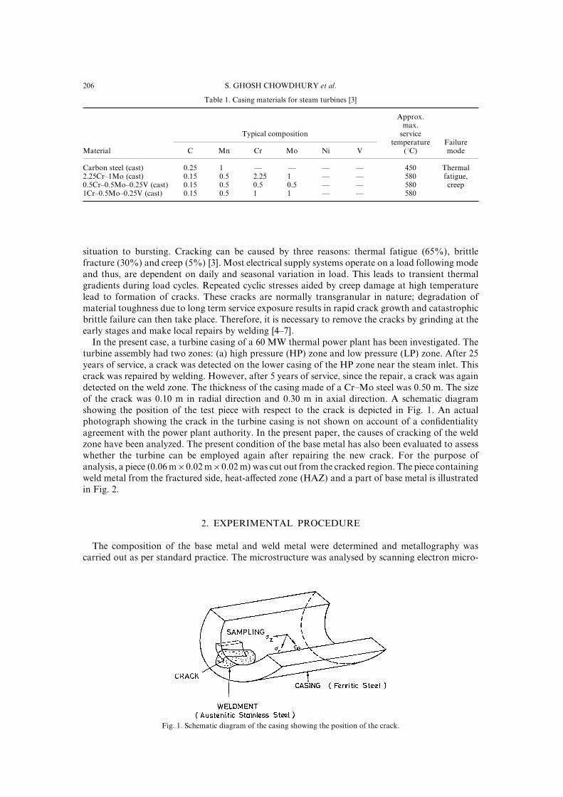
In the present case\ a turbine casing of a 59 MW thermal power plant has been investigated[ Theturbine assembly had two zones] "a# high pressure "HP# zone and low pressure "LP# zone[ After 14years of service\ a crack was detected on the lower casing of the HP zone near the steam inlet[ Thiscrack was repaired by welding[ However\ after 4 years of service\ since the repair\ a crack was againdetected on the weld zone[ The thickness of the casing made of a CrÐMo steel was 9[49 m[ The sizeof the crack was 9[09 m in radial direction and 9[29 m in axial direction[ A schematic diagramshowing the position of the test piece with respect to the crack is depicted in Fig[ 0[ An actualphotograph showing the crack in the turbine casing is not shown on account of a con_dentialityagreement with the power plant authority[ In the present paper\ the causes of cracking of the weldzone have been analyzed[ The present condition of the base metal has also been evaluated to assesswhether the turbine can be employed again after repairing the new crack[ For the purpose ofanalysis\ a piece "9[95 m×9[91 m×9[91 m# was cut out from the cracked region[ The piece containingweld metal from the fractured side\ heat!a}ected zone "HAZ# and a part of base metal is illustratedin Fig[ 1[
1[ EXPERIMENTAL PROCEDURE
The composition of the base metal and weld metal were determined and metallography wascarried out as per standard practice[ The microstructure was analysed by scanning electron micro!
Fig[ 0[ Schematic diagram of the casing showing the position of the crack[
196Failure analysis of a weld repaired steam turbine casing
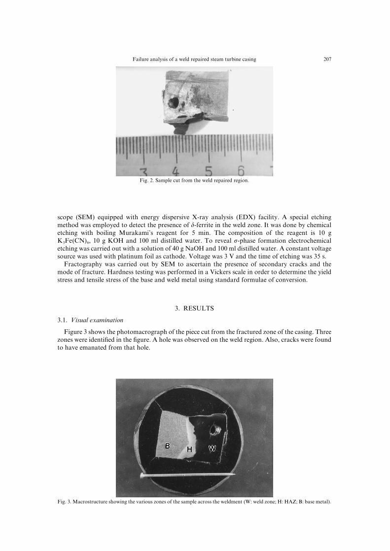
Fig[ 1[ Sample cut from the weld repaired region[
scope "SEM# equipped with energy dispersive X!ray analysis "EDX# facility[ A special etchingmethod was employed to detect the presence of d!ferrite in the weld zone[ It was done by chemicaletching with boiling Murakami|s reagent for 4 min[ The composition of the reagent is 09 gK2Fe"CN#5\ 09 g KOH and 099 ml distilled water[ To reveal s!phase formation electrochemicaletching was carried out with a solution of 39 g NaOH and 099 ml distilled water[ A constant voltagesource was used with platinum foil as cathode[ Voltage was 2 V and the time of etching was 24 s[
Fractography was carried out by SEM to ascertain the presence of secondary cracks and themode of fracture[ Hardness testing was performed in a Vickers scale in order to determine the yieldstress and tensile stress of the base and weld metal using standard formulae of conversion[
2[ RESULTS
2[0[ Visual examination
Figure 2 shows the photomacrograph of the piece cut from the fractured zone of the casing[ Threezones were identi_ed in the _gure[ A hole was observed on the weld region[ Also\ cracks were foundto have emanated from that hole[
Fig[ 2[ Macrostructure showing the various zones of the sample across the weldment "W] weld zone^ H] HAZ^ B] base metal#[
197 S[ GHOSH CHOWDHURY et al[
2[1[ Chemical analysis
The casing material was found to be 0CrÐ9[4Mo type with 9[07) carbon[ The weld metal wasfound to be] 9[07) C\ 9[21) Si\ 3) Mn\ 13) Cr\ 21) Ni\ 1) Mo\ ½0) Nb and balance Fe[This corresponds to a super austenitic alloy equivalent to modi_ed 799 H ð7Ł[
2[2[ Microstructure
Microstructure of the base metal shows a ferriteÐpearlite structure "Fig[ 3#\ which is expectedfrom this grade of steel under normalised condition ð8Ł[ Pearlite colonies have started to break up\but the process of disintegration is yet to be complete fully[ Fine particles of carbides are also seenwithin the ferrite grains[ Some elongated carbides are observed at the grain boundary[ By EDX\ itwas found that cementite in the pearlite colonies is enriched with other alloying elements\ i[e[\ Mn\Cr\ Mo[ The carbides within the grain could not be analyzed by SEM because of their small size[However\ as per literature\ those _ne precipitates should be complex alloy carbides ð8Ł[
The microstructure of the weld metal showed a cellular morphology of the austenite matrix "Fig[4#[ Microcracks have been found to nucleate from the hole[ Cracks are also observed along theaustenite grain boundaries[ The cracks are mostly intergranular in nature "Fig[ 5#[ EDX analysisshows the presence of alloy "Cr# rich phase along the grain boundary "Fig[ 6#[ Nb is also found inthis region[ The alloy additions change the temperature and composition of the peritectic:eutectictransformation and hence in~uence the solidi_cation mode of an austenitic weldment during weld!
Fig[ 3[ Microstructure of the base metal[
Fig[ 4[ Cellular microstructure of the weld metal[
198Failure analysis of a weld repaired steam turbine casing
Fig[ 5[ Intergranular crack propagating from a hole present in the weldment[
Fig[ 6[ "a# Cr!rich phase along the austenite grain boundary of the weldment^ "b# EDX of that phase[
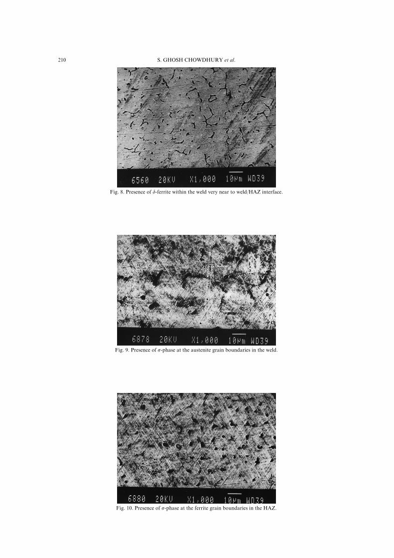
ing[ It is known that Si and Nb in addition to the impurity elements\ S\ P segregate at the dendriteinterfaces during solidi_cation which cause cracking ð09Ł[ Presence of d!ferrite is not observed inthe weldment\ except near the weld:base metal boundary on the weld metal side[ d!Ferrite is observedhere at the austenite grain boundaries "Fig[ 7#[ s!Phase is also observed at the grain boundaries inthe weldment very near to the HAZ after performing the special etching treatment "Fig[ 8#[ TheHAZ also shows the presence of s!phase at the ferrite grain boundaries "Fig[ 09#[
109 S[ GHOSH CHOWDHURY et al[
Fig[ 7[ Presence of d!ferrite within the weld very near to weld:HAZ interface[
Fig[ 8[ Presence of s!phase at the austenite grain boundaries in the weld[
Fig[ 09[ Presence of s!phase at the ferrite grain boundaries in the HAZ[
100Failure analysis of a weld repaired steam turbine casing
2[3[ Fracto`raphy
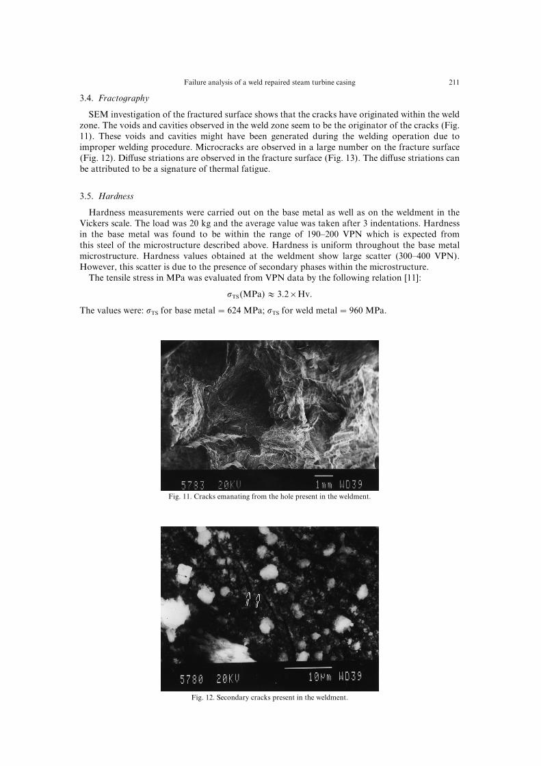
SEM investigation of the fractured surface shows that the cracks have originated within the weldzone[ The voids and cavities observed in the weld zone seem to be the originator of the cracks "Fig[00#[ These voids and cavities might have been generated during the welding operation due toimproper welding procedure[ Microcracks are observed in a large number on the fracture surface"Fig[ 01#[ Di}use striations are observed in the fracture surface "Fig[ 02#[ The di}use striations canbe attributed to be a signature of thermal fatigue[
2[4[ Hardness
Hardness measurements were carried out on the base metal as well as on the weldment in theVickers scale[ The load was 19 kg and the average value was taken after 2 indentations[ Hardnessin the base metal was found to be within the range of 089Ð199 VPN which is expected fromthis steel of the microstructure described above[ Hardness is uniform throughout the base metalmicrostructure[ Hardness values obtained at the weldment show large scatter "299Ð399 VPN#[However\ this scatter is due to the presence of secondary phases within the microstructure[
The tensile stress in MPa was evaluated from VPN data by the following relation ð00Ł]
sTS"MPa# ¼ 2[1×Hv[
The values were] sTS for base metal�513 MPa^ sTS for weld metal�859 MPa[
Fig[ 00[ Cracks emanating from the hole present in the weldment[
Fig[ 01[ Secondary cracks present in the weldment[
101 S[ GHOSH CHOWDHURY et al[
Fig[ 02[ Di}use striations observed at the fracture surface[
3[ ANALYSIS AND DISCUSSION
Considering the above microstructural features\ it is necessary to understand the following pointsin order to analyze the failure in the repaired weld joint]
"a# Is the base metal in good metallurgical condition<"b# Was the choice of the austenitic alloy as the repair weld _ller metal proper<"c# If the choice of the _ller metal was not correct\ what could have been a better choice<
For a repair weld\ the _rst condition to satisfy is that the _ller metal must show a good weldability[Then the essential requirement is that the ductility of the weld metal and the HAZ should be equalif not better than the base metal[
Analysis of the weld metal showed that the material used for welding is di}erent from the basemetal and it is austenitic in nature[ In case of adverse environment\ i[e[\ at high temperature\ thecharacteristics of the _ller metals and base metal should ideally be matched as closely as possible[Therefore\ _ller material of the same or slightly higher alloying content can be used for welding CrÐMo steels\ e[g[\ 0[14CrÐ9[4Mo _ller metal can be used for welding 9[4CrÐ9[4Mo\ 0CrÐ9[4Mo and0[14CrÐ9[4Mo steels ð01Ł[ However\ after welding\ the components should be annealed to relieveresidual stress[ Preheating of the low alloy ferritic steels is a common practice to avoid the formationof martensite in the HAZ of an alloy steel weldment like CrÐMo steel[ The tendency for martensiteformation is reduced to a considerable extent and even eliminated when austenitic steel is used as_ller metal[
For a large component like the casing\ heat!treatment\ preheating and post!weld heating aredi.cult[ To avoid the heat treatment of thicker sections\ austenitic stainless steel of AISI 298 or 209are often employed for minor repair welding of CrÐMo steels ð01Ł[ Stainless steel weld metal hashigher as!welded ductility than CrÐMo steel[ For these reasons\ the majority of welding stresses arerelieved through yielding during the welding operations[ It also resists decarburization and thermalshock[ As austenitic steels are richer in alloying elements\ the weld metal near the fusion line getsdiluted and the HAZ gets enriched in alloying elements[ The dilution e}ect is important sincethe microstructure in steel or metallic alloy is a function of the chemical composition and theheating:cooling rates[ This\ in a way\ can reduce the susceptibility for martensite formation[
Another reason for the use of austenitic steel is the susceptibility of ferritic steels to type IVcracking\ i[e[\ cracking during post!weld heat treatment ð02Ł[ This cracking occurs at the edges ofHAZ material adjacent to una}ected base metal[ Improved heat treatments have been found toeliminate the propensity for type IV cracking[ However\ it requires furnace facilities capable ofimplementing the stress!relief treatment of the entire component[ Otherwise\ the only alternative isto incorporate a 09Ð19) safety margin in terms of stress into the design[
The above points of discussion suggest that repair welding of low alloy ferritic steel by austenitic_ller metal is easier at inaccessible regions of service induced cracks by avoiding the preheating and
102Failure analysis of a weld repaired steam turbine casing
the post!weld heat treatments[ However\ it has been found that this austenitic _ller metal is notsatisfactory if the welded joint is subjected to cyclic temperature service or a service temperaturewhere either C!migration or s!phase formation can take place ð01Ł[ In the present case\ chemicalanalysis of the base metal and the weldment has shown that the amount of carbon is the same inboth the cases "9[07)#[ Hence\ the possibility of C!migration can be ruled out[
3[0[ Condition of the base metal
The mechanical properties of a CrÐMo steel are derived from a microstructure which consists ofan alloyed matrix and alloy carbides as secondary phases ð1Ł[ The initial microstructure in suchsteels can be ferriteÐpearlite or bainite[ The strength is derived from the combination of solidsolution and precipitation e}ects in the early stage\ solid solution e}ect is the largest contribution[As time progresses\ the precipitation of alloy carbides contributes more to the strength and this isknown as secondary hardening ð8Ł[ Secondary hardening allows higher tempering temperature andthis increases the range of service temperature[ The secondary hardening peak depends on thecarbide forming elements[ The degree of secondary hardening can be increased by increasing themismatch between the matrix and the precipitate[ This can be achieved by alloy addition[ However\as welding is an important factor\ selection of alloying elements will be governed by weldability ofthe material ð03Ł[ With sustained exposure at high temperature\ the strengthening of the carbides isreduced as the carbides coarsen and convert into stable but weaker carbide structure[
In the case of the ferriteÐpearlite microstructure which is the case in this study\ the cementiteplatelets break up and gradually spheroidise[ There is also a variation of the partitioning of alloyingelements like Cr\ Mo between the matrix and the carbides[ There have been several investigationsto understand the nature of microstructural changes and consequent degradation[ A classi_cationof di}erent microstructures done by Toft and Marsden ð04Ł is shown in Table 1[ In terms of themorphology and size of carbides that we have observed\ the microstructure in the base metal matcheswith the Grade {{C|| in that table[ This indicates that the base metal still retains a microstructure thatshould not lead to failure[ The question then is*why the base metal developed a crack in the _rstplace[ A possibility is that a defect was present from the manufacturing stage that had initiated thecrack[ However\ without having any documentary evidence\ it is not possible to conclude on thisaspect[
3[1[ Condition of the weld metal
From the chemical analysis\ the weld metal was found to be closer to modi_ed 799H ð7Ł[ Thisalloy contains Nb which helps to have an increase in corrosion resistance and retain high strengthat moderately high temperature[ Also\ presence of Nb increase its resistance to sensitization duringwelding or service exposure at high temperatures ð05\ 06Ł[ This alloy has similar thermal conductivityin comparison to austenitic steels^ but the thermal expansion coe.cient is intermediate between theaustenitic stainless steels and the ferritic steels ð07Ł[
It has long been recognised that austenitic stainless steels are subject to cracking in either theweld metal or the heat!a}ected zone "HAZ# or in both ð08Ł[ The type and origin of cracking hasbeen associated with the low liquation temperature of various microstructural constituents ð19Ł[
Table 1[ Stages of carbide spheroidization in 0) CrÐ9[4) Mo steel ð04Ł
Stage Degree of spheroidization
A Structure consisting of ferrite and pearlite[B First stage of carbide spheroidization along with appearance of small carbide particles at the grain boundaries[C Intermediate stage of spheroidization^ distinct signs of carbide spheroidization in the pearlite areas although
lamellar nature is still evident[ Increased carbide precipitation within the ferrite grains as well as along the grainboundaries[
D Spheroidization is virtually complete\ but they are still grouped in the original pearlite patterns[E Spheroidization is complete and the carbides are dispersed bearing little trace of the original pearlite areas[F Marked increase in the size of some of the carbide particles\ partly due to coalescence[
103 S[ GHOSH CHOWDHURY et al[
The problem is also known to be severe in thick sections because of greater constraint ð10Ł[ Recently\liquation cracking in the HAZ of AISI 236 was found to be associated with eutectics of Nb!richphases at grain boundaries or interfaces ð11Ł[
To assess the worth of alloy 799H as a _ller metal\ the Schae/er diagram "Fig[ 03# can bemade use of[ Use of the Schae/er diagram is a well!known technique to understand the expectedmicrostructure in an austenitic weld metal[ The chromium and nickel equivalents in the X and Yaxis in the diagram are calculated as follows]
Creq �)Cr¦)Mo¦0[4")Si#¦9[4")Nb#\ "0#
Nieq �)Ni¦29")C#¦9[4")Mn#[ "1#
On this basis\ the low alloy ferritic steel in the present case corresponds to the point {{P||"Creq �0[44\ Nieq �4[8# and that of the weld metal corresponds to point {{Q|| "Creq �16[12 andNieq �28[3# in the diagram "Fig[ 03#[ Since point {{P|| lies in the martensite region and point {{Q||lies in the fully austenite region\ that there is a possibility of a large amount of dilution by the basemetal which melts when the weld metal is deposited[ It has been estimated from the diagram thatin order to have a microstructure which would have martensite phase other than austenite\ a dilutionof the order of 54) is needed[ For full martensite\ a dilution of 66) is required[ Practically\ theamount of dilution mentioned above is impossible to achieve[ But to have d!ferrite as a secondaryphase\ the required dilution would be much less and achievable[
Fully austenitic steel is liable to hot cracking which occurs during weld metal solidi_cation[ Thiscracking takes place due to segregation of impurity elements such as S\ P and other elements leadingto low melting point phases[ It is well known that the d!ferrite in the HAZ or weld in austenitic steelbene_ts resistance to hot cracking[ A certain amount of d!ferrite "4Ð7 vol)# will scavenge theimpurities and take care of a certain amount of thermal strain ð12Ł[ While the primary reason forhot cracking is segregation of deleterious elements at the grain boundaries\ an important contributingfactor is the high coe.cient of thermal expansion due to which a large amount of strain accumulatesduring solidi_cation of the weld metal[ The Schae/er diagram is a good pointer to indicate thesolidi_cation mode of stainless steels[
The cracks that have been observed in the weld metal in the present case could be due to one ormore of the following reasons] "i# hot cracking as explained above^ "ii# due to transformation of d!ferrite to s!phase^ the d!ferrite could be formed during welding^ "iii# due to thermal fatigue damage[Hot cracking as mentioned earlier is due to the presence of impurities at the grain boundaries[
Fig[ 03[ Schae/er diagram indicating possibility of d!ferrite formation due to dilution[
104Failure analysis of a weld repaired steam turbine casing
However\ such elements were not detected^ hence\ the presence of hot cracking by impurity can beruled out[ However\ the second possibility i[e[\ transformation of d!ferrite cannot be ruled out[According to Schae/er diagram\ the weld metal is in the fully austenitic region[ Also\ by usingboiling Murakami|s reagent as an etchant\ no d!ferrite was observed in the weldment[ However\ d!ferrite was observed near the HAZ "within the weldment# as well as within the HAZ[ However\ thevolume fraction of d!ferrite is more in the HAZ[ The formation of this can be explained if the e}ectof dilution can be taken into account[ Migration of Cr is prominent among the other species becauseof its size factor[ Cr having the smallest atomic diameter can di}use easily compared to Ni as wellas Mo[ On the basis of EDX analysis "Fig[ 04# the weld metal near the HAZ has Creq × 09 andNieq ³ 19[ Similar analysis shows that the HAZ has Creq × 14 and Nieq ³ 04[ The above two casesare marked as X and Y\ respectively\ in the Schae/er diagram "Fig[ 03#[ As Creq increases and Nieqdecreases\ the propensity of d!ferrite formation increases[
EDX analysis at the austenite grain boundaries shows considerable amount of second phases"Fig[ 05"a##\ which are enriched with Nb "Fig[ 05"b##[ Nb being more reactive compared to Cr\forms more stable carbides or carbonitrides[ Constitutional liquation of these compounds occurs inNb bearing austenitic alloys to form a low melting point eutectic with austenite ð11Ł[ It has beenobserved metallographically by Messler and Li ð13Ł that a eutectic of austenite and Nb rich phasewas present at the _nal stages of solidi_cation of the liquated grain boundaries in an austenitic steel[They also\ showed similar behaviour of signi_cant Nb enrichment at the grain boundary comparedto the matrix[ It was reported that a high C¦N content relative to Nb content increased theliquation temperature of grain boundary eutectic\ reducing cracking susceptibility[ However\ in thepresent case\ the Nb content is quite high and that lowered the liquation temperature and increasedthe cracking susceptibility\ probably by forming Fe1Nb[
After high temperature exposure the d!ferrite converts to s!phase and alloy carbides by a twostep eutectoid reaction ð14Ł[ The _rst step leads to the formation of austenite and a Cr!rich carbide"M12C5# by a lamellar eutectoid reaction[ s!Phase forms as a result of a second eutectoid reaction[Once the s!phase forms\ the microcracks formed due to thermal stress will propagate fast with theaid of s!phase embrittlement[ Even voids can generate near the grain boundary carbides as well asaround the s!phase[ In the following discussion\ the intensity of thermal fatigue to initiate crackswithin the weldment will be analyzed[
3[2[ Ori`in of stress
Two types of stresses\ mainly found in the casing are thermal stresses due to temperature cyclingand mechanical stress due to the steam pressure[ In the following\ the stress components to be used
Fig[ 04[ EDX analysis at the austenite grain boundary near weld:HAZ interface[
105 S[ GHOSH CHOWDHURY et al[
"a#
"b#
Fig[ 05[ "a# Presence of Nb!rich phase at the austenite grain boundary^ "b# EDX of that phase[
are as follows] su is the circumferential stress\ sz is the longitudinal stress and sr is the radial stress"Fig[ 0#[
Considering the solution of thermal stress in a hollow cylinder with inner and outer radius\ a andb\ respectively\ the stress components are as follows ð15Ł]
sr �aE
0−n
0
r10r1−a1
b1−a1 gb
a
Trdr−gb
a
Trdr1\ "2#
su �aE
0−n
0
r10r1¦a1
b1−a1 gb
a
Trdr¦gb
a
Trdr−Tr11\ "3#
sz �aE
0−n01
b1−a1 gb
a
Trdr−T1[ "4#
a is the coe.cient of thermal expansion\ n is Poisson|s ratio\ E is the Young|s modulus\ r is thepoint from the centre where the stress is to be calculated and T is the temperature[ Considering steadytemperature distribution and Ta\ Tb as the inner and outer surface temperatures\ the distribution oftemperature as a function of r from the centre can be expressed as
T�Tb¦DT =
logbr
logba
[ "5#
106Failure analysis of a weld repaired steam turbine casing
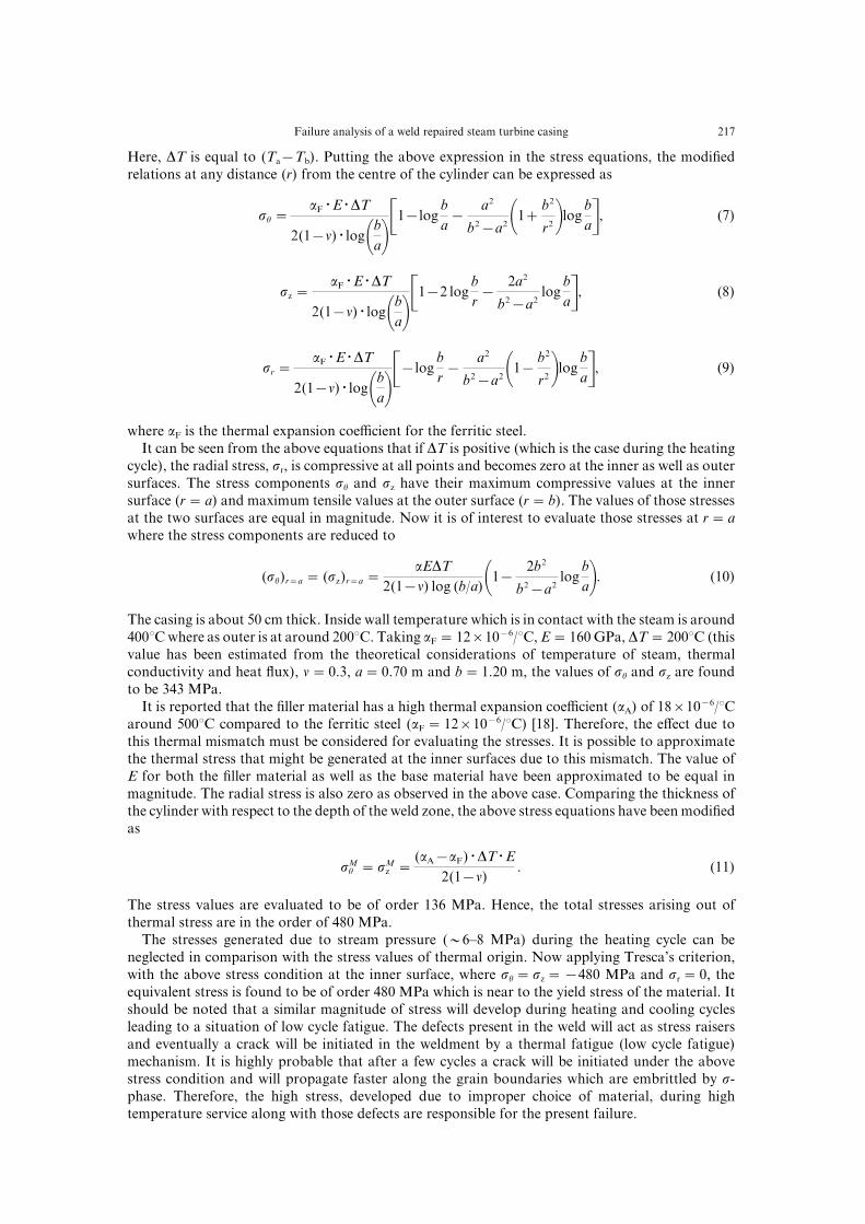
Here\ DT is equal to "Ta−Tb#[ Putting the above expression in the stress equations\ the modi_edrelations at any distance "r# from the centre of the cylinder can be expressed as
su �aF =E =DT
1"0−n# = log0ba1$0−log
ba−
a1
b1−a100¦b1
r11logba%\ "6#
sz �aF =E =DT
1"0−n# = log0ba1$0−1 log
br−
1a1
b1−a1log
ba%\ "7#
sr �aF =E =DT
1"0−n# = log0ba1$−log
br−
a1
b1−a100−b1
r11logba%\ "8#
where aF is the thermal expansion coe.cient for the ferritic steel[It can be seen from the above equations that if DT is positive "which is the case during the heating
cycle#\ the radial stress\ sr\ is compressive at all points and becomes zero at the inner as well as outersurfaces[ The stress components su and sz have their maximum compressive values at the innersurface "r� a# and maximum tensile values at the outer surface "r� b#[ The values of those stressesat the two surfaces are equal in magnitude[ Now it is of interest to evaluate those stresses at r� awhere the stress components are reduced to
"su#r�a � "sz#r�a �aEDT
1"0−n# log "b:a#00−1b1
b1−a1log
ba1[ "09#
The casing is about 49 cm thick[ Inside wall temperature which is in contact with the steam is around399>C where as outer is at around 199>C[ Taking aF �01×09−5:>C\ E�059 GPa\ DT�199>C "thisvalue has been estimated from the theoretical considerations of temperature of steam\ thermalconductivity and heat ~ux#\ n�9[2\ a�9[69 m and b�0[19 m\ the values of su and sz are foundto be 232 MPa[
It is reported that the _ller material has a high thermal expansion coe.cient "aA# of 07×09−5:>Caround 499>C compared to the ferritic steel "aF �01×09−5:>C# ð07Ł[ Therefore\ the e}ect due tothis thermal mismatch must be considered for evaluating the stresses[ It is possible to approximatethe thermal stress that might be generated at the inner surfaces due to this mismatch[ The value ofE for both the _ller material as well as the base material have been approximated to be equal inmagnitude[ The radial stress is also zero as observed in the above case[ Comparing the thickness ofthe cylinder with respect to the depth of the weld zone\ the above stress equations have been modi_edas
sMu �sM
z �"aA−aF# =DT =E
1"0−n#[ "00#
The stress values are evaluated to be of order 025 MPa[ Hence\ the total stresses arising out ofthermal stress are in the order of 379 MPa[
The stresses generated due to stream pressure "½5Ð7 MPa# during the heating cycle can beneglected in comparison with the stress values of thermal origin[ Now applying Tresca|s criterion\with the above stress condition at the inner surface\ where su �sz �−379 MPa and sr �9\ theequivalent stress is found to be of order 379 MPa which is near to the yield stress of the material[ Itshould be noted that a similar magnitude of stress will develop during heating and cooling cyclesleading to a situation of low cycle fatigue[ The defects present in the weld will act as stress raisersand eventually a crack will be initiated in the weldment by a thermal fatigue "low cycle fatigue#mechanism[ It is highly probable that after a few cycles a crack will be initiated under the abovestress condition and will propagate faster along the grain boundaries which are embrittled by s!phase[ Therefore\ the high stress\ developed due to improper choice of material\ during hightemperature service along with those defects are responsible for the present failure[
107 S[ GHOSH CHOWDHURY et al[
4[ CONCLUSIONS
The base material consisting of ferriteÐpearlite microstructure did not show any appreciableamount of spheroidization[ However\ the weldment is found to be degraded[ Dilution of alloyingelements took place and d!ferrite was observed at the interface of the weldment and HAZ aspredicted by the Schae/er diagram[ These d!ferrites appeared to transform to alloy carbides and s!phase during high temperature service exposure[ The di}erence between the thermal expansioncoe.cients of ferritic and austenitic stainless steel led to the generation of an extra stress in additionto the usual thermal stress due to the thicker section of the casting[ The resultant stress "379 MPa#was near to the yield stress which indicates that the weld zone experienced a typical situation of lowcycle fatigue[ Holes and cavities which were present in the weld seemed to be responsible forinitiating the cracks[ The presence of striations on the fracture surface con_rmed thermal fatigue asthe failure mode and cracks after the initiation from the defects\ grew faster along the austenitegrain boundaries embrittled by s!phase and led to failure of the component[
The correct choice of the _ller metal should have been a high Ni!base alloy having a similarcoe.cient of thermal expansion as the ferritic steel base metal[
Acknowled`ements*The authors wish to acknowledge Dr G[ Sridhar\ Dr S[ Tarafdar\ Dr N[ Parida and Mr Rajeev Kumarfor their stimulating discussions and help in carrying out the experiments[ The authors are grateful to Mr D[ Sanyal andMrs S[ Mukhopadhyay for useful discussions on thermal stress!analysis[ The authors are grateful to Prof[ P[ RamachandraRao\ Director\ National Metallurgical Laboratory\ Jamshedpur\ for his kind permission to publish this paper[
REFERENCES
0[ Modern Power Station Practice\ British Electricity International[ Pergamon Press\ 2rd edn\ 0881[1[ Baker\ R[ G[ and Nutting\ J[\ JISI\ July\ 0848\ p[ 146[2[ Viswanathan\ R[\ Dama`e Mechanisms and life Assessment of Hi`h Temperature Components[ ASM International\ Metals
Park\ Ohio\ 0878\ p[ 297[3[ Brett\ S[ J[\ Materials Development in Turbo!Machinery Desi`ns[ The Institute of Metals\ London\ 0878\ p[ 055[4[ Sugita\ Y[\ Sugiura\ T[\ Fujiwara\ T[ and Tomoda\ K[\ First Intl[ Conf[ on Microstructure and Mechanical Properties of
A`in` Materials\ TMS\ 0882\ p[ 80[5[ Yosh\ D[ and Caploon\ A[\ Weldin` J\ 0881\ 60"1#\ 18[6[ David\ T[ J[\ in Thermal Stress and Thermal Fati`ue\ ed[ D[ J[ Litter[ Butterworths\ London\ 0858\ p[ 074[7[ Viswanathan\ R[\ Dama`e Mechanisms and Life Assessment of Hi`h Temperature Components[ ASM International\
Metals Park\ OH\ 0878\ p[ 309\ cf 21[8[ Orr\ J[\ Beckitt\ F[ R[ and Fawkes\ G[ D[\ Ferritic Steel for Fast Reactor Steam Generators[ BNES\ London\ 0864\ p[ 80[
09[ Shankar\ V[\ Gill\ T[ P[ S[\ Mannan\ S[ L[ and Rodriguez\ P[\ Internal report IGC!008\ Indira Gandhi Centre for AtomicResearch "0880#[


![MACROECONOMICS [Repaired]](https://static.documents.pub/doc/80x56/5881967f1a28ab0d358b69c5/macroeconomics-repaired.jpg)


![Report.pptx [Repaired]](https://static.documents.pub/doc/80x56/577cc6f51a28aba7119fa4da/reportpptx-repaired.jpg)
