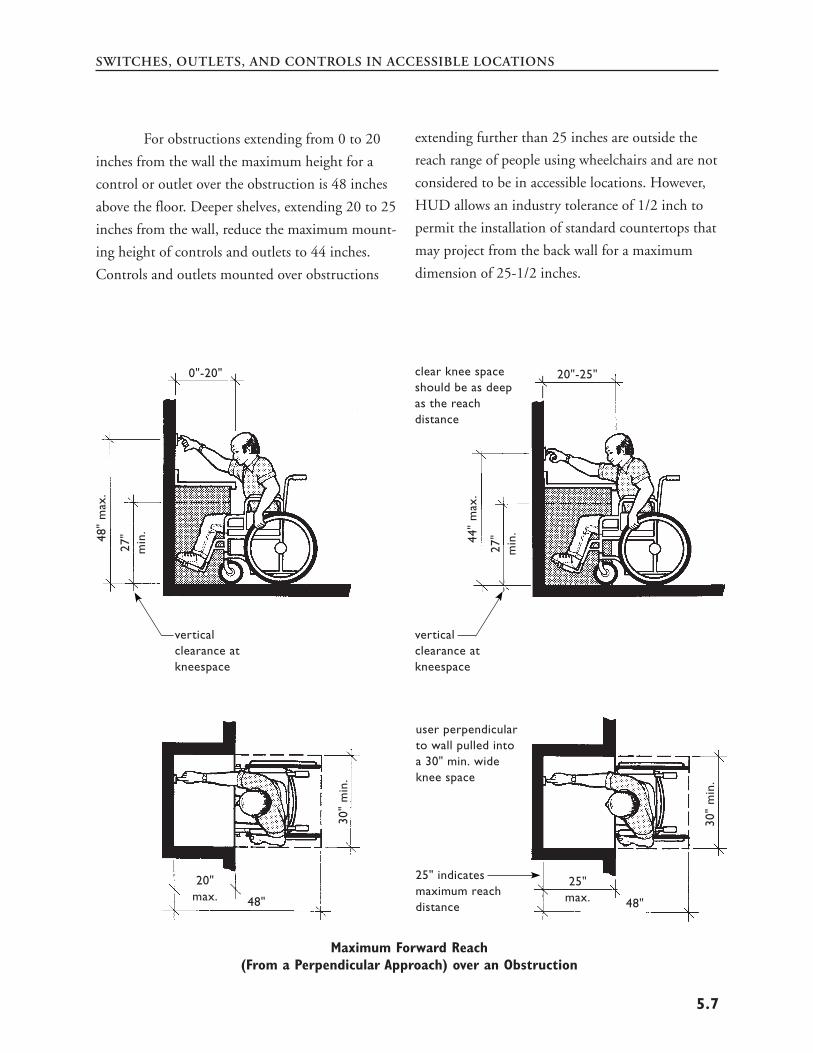
ASSIST D BUILDERS IN M ACCESSIBILITY REQUIREMENTS FAIR HOUSING ACT F AIR HOUSING ACT DESIGN M A MANUAL TO ESIGNERS AND EETING THE OF THE ANUAL U. S. Department of Housing and Urban Development Office of Fair Housing and Equal Opportunity Office of Housing
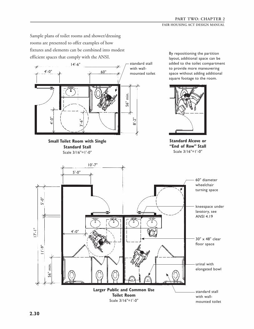
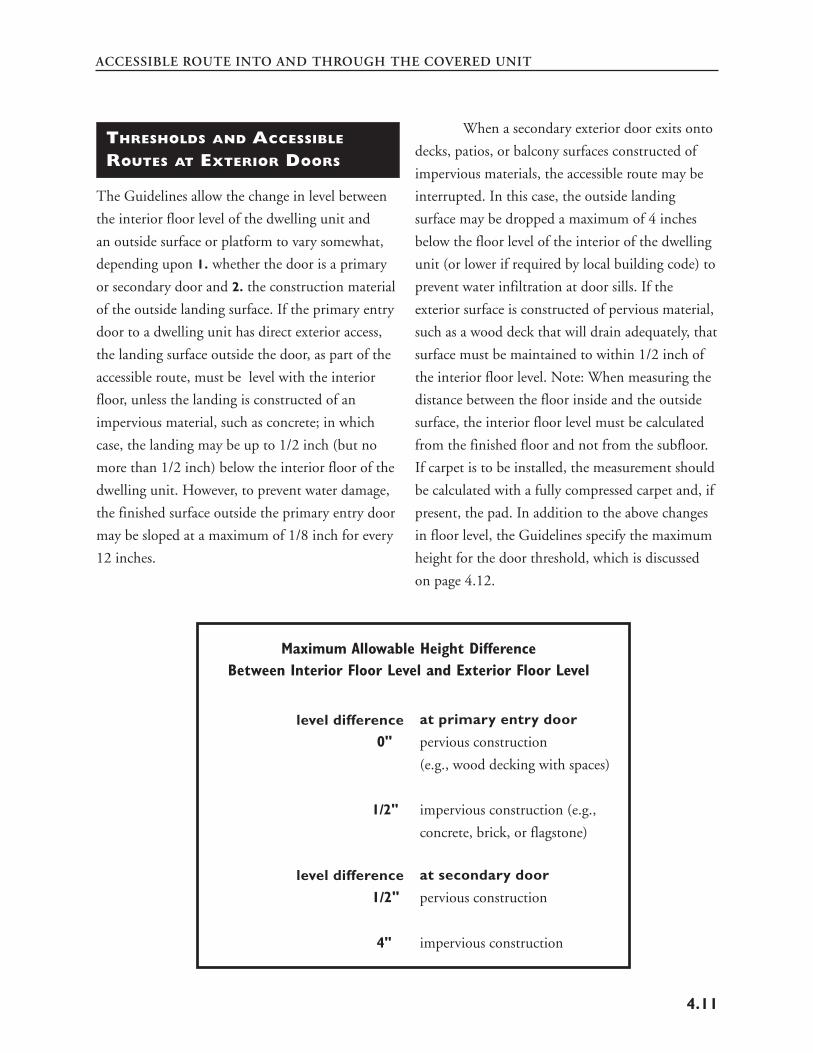
Transcript
ASSIST
D BUILDERS
IN M
ACCESSIBILITY REQUIREMENTS
FAIR HOUSING ACT
FAIR HOUSING ACT
DESIGN M
A MANUAL TO
ESIGNERS AND
EETING THE
OF THE
ANUAL
U. S. Department
of Housing and Urban Development
Office of Fair Housing and Equal Opportunity
Office of Housing
FAIR HOUSING ACT
DESIGN MANUAL
A MANUAL TO ASSIST
DESIGNERS AND BUILDERS
IN MEETING THE
ACCESSIBILITY REQUIREMENTS
OF THE FAIR HOUSING ACT
designed and developed by
Barrier Free Environments, Inc.
Raleigh, North Carolina
for
The U.S. Department of Housing
and Urban Development
Office of Fair Housing and Equal Opportunity
and the Office of Housing
Contract # 15903
August 1996
Revised April 1998
CREDITS
Project Director Ronald L. Mace, FAIA
Project Manager Leslie C. Young
Technical Assistance Cheryl Kent , FHEO, HUD
Authorship Leslie C. Young
Ronald L. Mace
Geoff Sifrin Architectural Design
and Conceptual Illustration Ronald L. Mace
Leslie C. Young
Rex J. Pace
Geoff Sifrin
Graphic Design Christopher A. B. McLachlan
Illustration Rex J. Pace
Mark Pace
Photography Kelly Houk
Leslie C. Young
Acknowledgements Creation of this design manual involved the close cooperation of many people. Among them are the reviewers and technical staff at the Department of Housing and Urban Development, including Cheryl Kent, Judy Keeler, Merle Morrow, Alan Rothman, Nelson Carbonell, and Gail Williamson.
Special appreciation to the Barrier Free Environments, Inc. staff who contributed to this publication, including Leslie Young, Rex Pace, and Ron Mace. Special thanks also to Geoff Sifrin in South Africa and Lucy Harber.
Every attempt was made with this project to provide a concise and easy-to-follow guide on the construction requirements of the Fair Housing Act. Our hope is that the construction and disability communities to whom this manual is directed will be able to use and benefit from our efforts.
CONTENTS
Part One page 1
Part Two
page 1.1
page 2.1
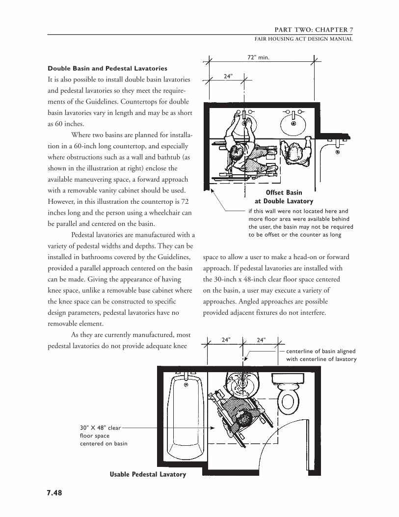
page 3.1
page 4.1
page 5.1
page 6.1
page 7.1
page 7.31
Part Three
page A.1
page B.1
page C.1
INTRODUCTION
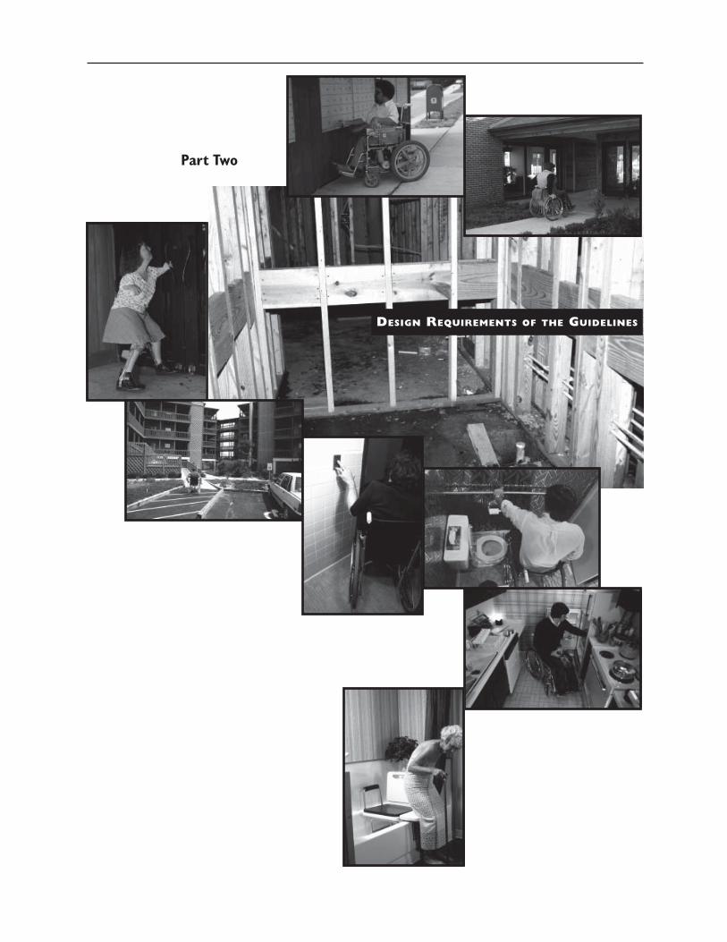
DESIGN REQUIREMENTS OF THE GUIDELINES
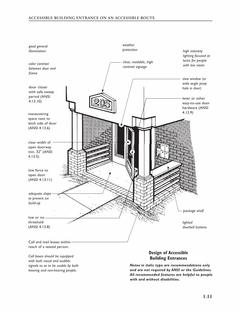
Chapter One: REQUIREMENT 1 – Accessible
Building Entrance on an Accessible Route
Chapter Two: REQUIREMENT 2 – Accessible and
Usable Public and Common Use Areas
Chapter Three: REQUIREMENT 3 – Usable Doors
Chapter Four: REQUIREMENT 4 – Accessible
Route into and Through the Covered Unit
Chapter Five: REQUIREMENT 5 – Light Switches,
Electrical Outlets, Thermostats, and Other
Environmental Controls in Accessible Locations
Chapter Six: REQUIREMENT 6 – Reinforced Walls
for Grab Bars
Chapter Seven: REQUIREMENT 7 – Usable
Kitchens and Bathrooms
■ PART A: Usable Kitchens
■ PART B: Usable Bathrooms
APPENDICES
■ Product Resources and Selected References
■ Fair Housing Accessibility Guidelines
■ Supplemental Notice: Fair Housing
Accessibility Guidelines: Questions and Answers
About the Guidelines
INTRODUCTION
Part One
INTRODUCTION
INTRODUCTION
THE FAIR HOUSING ACT
Title VIII of the Civil Rights Act of 1968, com
monly known as the Fair Housing Act, prohibits
discrimination in the sale, rental, and financing of
dwellings based on race, color, religion, sex, and
national origin. In 1988, Congress passed the Fair
Housing Amendments Act. The Amendments
expand coverage of Title VIII to prohibit discrimi
natory housing practices based on disability1 and
familial status. Now it is unlawful to deny the
rental or sale of a dwelling unit to a person because
that person has a disability.
As a protected class, people with disabilities
are unique in at least one respect because they are
the only minority that can be discriminated against
solely by the design of the built environment. The
Fair Housing Act remedies that in part by estab
lishing design and construction requirements for
multifamily housing built for first occupancy after
March 13, 1991. The law provides that a failure to
design and construct certain multifamily dwellings
to include certain features of accessible design will
be regarded as unlawful discrimination.
The design and construction requirements
of the Fair Housing Act apply to all new multifam
ily housing consisting of four or more dwelling
units. Such buildings must meet specific design
requirements so public and common use spaces
and facilities are accessible to people with disabili
ties. In addition, the interior of dwelling units
covered by the Fair Housing Act must be designed
so they too meet certain accessibility requirements.
The Fair Housing Act is intended to place
“modest accessibility requirements on covered
multifamily dwellings .... These modest require
ments will be incorporated into the design of new
buildings, resulting in features which do not look
unusual and will not add significant additional
costs” (House Report 7112 at 25 and 18 ). Fair
Housing units are not fully accessible, nor are they
purported to be; however, new multifamily housing
built to comply with the Guidelines will be a
dramatic improvement over units built in the past.
The Fair Housing Act gives people with
disabilities greater freedom to choose where they
will live and greater freedom to visit friends and
relatives. But the Fair Housing Act has other broad
implications. It proactively addresses the needs of
an evolving population, looking ahead at future
needs. With the aging of the population and the
increase in incidence of disability that accompanies
aging, significant numbers of people will be able to
remain in and safely use their dwellings longer. For
example, housing designed in accordance with the
Fair Housing Act will have accessible entrances,
wider doors, and provisions to allow for easy
installation of grab bars around toilets and bath
tubs, i.e., features that make housing safer and
more responsive to all users.
1The Fair Housing Act statute uses the term “handicap”; however, this manual uses the terms “disability” or “persons with disabilities” to the greatest extent possible to be consistent with current preferred terminology as reflected in the Americans with Disabilities Act of 1990.
THE ROLE OF HUD The U.S. Department of Housing and Urban
Development (HUD) is the Federal agency respon
sible for enforcement of compliance with the Fair
Housing Act. On January 23, 1989, HUD pub
lished its final rule implementing the Fair Housing
Act. In the preamble to this rule, HUD indicated
that it would provide further guidance on meeting
the new construction requirements of the Act by
developing accessibility guidelines. The preamble
stated that until these guidelines are published,
designers and builders may be guided by the
requirements of the ANSI A117.1-1986 American
National Standard for Buildings and Facilities –
Providing Accessibility and Usability for Physically
Handicapped People. More information on the
ANSI standard appears on page 13.
The final Fair Housing Accessibility
Guidelines (the Guidelines) were published on
March 6, 1991 (56 Federal Register 9472-9515,
24 CFR3 Chapter I, Subchapter A, Appendix II
and III). The Guidelines provide technical guid
ance on designing dwelling units as required by the
Fair Housing Act. The Guidelines are not manda
tory, but are intended to provide a safe harbor for
compliance with the accessibility requirements of
the Fair Housing Act. The Guidelines are included
in this manual as Appendix B.
The Guidelines published on March 6,
1991, remain unchanged. However, on June 28,
1994, HUD published a supplemental notice to
the Guidelines, “Supplement to Notice of Fair
Housing Accessibility Guidelines: Questions and
Answers About the Guidelines.” This supplemental
notice reproduces questions that have been most
frequently asked by members of the public, and
CFR = Code of Federal Regulations
FAIR HOUSING ACT DESIGN MANUAL
HUD’s answers to those questions. The Supplement
also is included in this manual as Appendix C.
Under the Fair Housing Act, HUD is not
required to review builders’ plans or issue a certi
fication of compliance with the Fair Housing Act.
HUD prepared the Guidelines and will answer
technical questions. HUD also provides this pub
lication as additional guidance.
The burden of compliance rests with the
person or persons who design and construct covered
multifamily dwellings. HUD or an individual who
thinks he or she may have been discriminated
against may file a complaint against the building
owner, the architect, the contractor, and any other
persons involved in the design and construction of
the building. See page 22 for additional information
on enforcement.
THE PURPOSE OF THE MANUAL
This design manual has been produced by HUD
to assist designers, builders, and developers in
understanding and conforming with the design
requirements of the Fair Housing Act. It contains
explanations and uses detailed illustrations to
explain the application of the Guidelines to all
aspects of multifamily housing projects.
The manual consists of three parts:
Part One: THE INTRODUCTION contains an
overview of the Fair Housing Act, outlines other
national laws and standards that regulate accessible
design, presents the types of buildings/dwellings
that are covered by the Fair Housing Act, and
gives a brief discussion of the different types of
disabilities.
2
3
INTRODUCTION
Part Two: THE DESIGN REQUIREMENTS OF
THE GUIDELINES is a detailed, illustrated explana
tion of the seven requirements of the Fair Housing
Accessibility Guidelines.
Part Three: THE APPENDIX contains additional
information that may be useful to anyone needing
to be familiar with the design requirements of the
Fair Housing Act. Included are a list of product
resources, a list of selected references, a reprint of
the Guidelines, and a reprint of the Supplemental
Notice to the Guidelines.
LAWS AND CODES
THAT MANDATE ACCESSIBILITY
Over the past two and a half decades, several
statutes have been enacted at various levels of
government that ensure nondiscrimination against
people with disabilities, both in the design of the
built environment and in the manner that pro
grams are conducted. Even though this manual
addresses the application of the Fair Housing Act
and the Guidelines, certain dwellings, as well as
certain public and common use areas, may be
covered by several of the laws listed below. A brief
synopsis of the landmark legislation follows to
show where the Fair Housing Act fits into the
overall history of accessibility legislation.
THE ARCHITECTURAL
BARRIERS ACT (1968) This Act stipulates that all buildings, other than
privately owned residential facilities, constructed by
or on behalf of, or leased by the United States, or
buildings financed in whole or in part by the
United States must be physically accessible for
people with disabilities. The Uniform Federal
Accessibility Standards (UFAS) is the applicable
standard.
SECTION 504 OF THE
REHABILITATION ACT (1973) Under Section 504 of the Rehabilitation Act of
1973 as amended, no otherwise qualified indi
vidual with a disability may be discriminated
against in any program or activity receiving federal
financial assistance. The purpose of Section 504 is
to eliminate discriminatory behavior toward people
with disabilities and to provide physical accessibil
ity, thus ensuring that people with disabilities will
have the same opportunities in federally funded
programs as do people without disabilities.
Program accessibility may be achieved by
modifying an existing facility, or by moving the
program to an accessible location, or by making
other accommodations, including construction of
new buildings. HUD’s final regulation for Section
504 may be found at 24 CFR Part 8. Generally,
the UFAS is the design standard for providing
physical accessibility, although other standards
which provide equivalent or greater accessibility
may be used.
THE FAIR HOUSING ACT OF 1968, AS AMENDED
The Fair Housing Act provides equal opportunities
for people in the housing market regardless of
disability, race, color, sex, religion, familial status or
national origin, regardless of whether the housing is
3
PART ONE
publicly funded or not. This includes the sale,
rental, and financing of housing, as well as the
physical design of newly constructed multifamily
housing. The Fair Housing Act is discussed in more
detail in the next section, “General Provisions of
the Fair Housing Act.”
THE AMERICANS WITH
DISABILITIES ACT (1990) The Americans with Disabilities Act (ADA) is a
broad civil rights law guaranteeing equal opportu
nity for individuals with disabilities in employ
ment, public accommodations, transportation,
state and local government services, and telecom
munications. Title III of the Act covers all private
establishments and facilities considered “public
accommodations,” such as restaurants, hotels, retail
establishments, doctors’ offices, and theaters.
People with disabilities must have equal opportu
nity in these establishments, both in terms of
physical access and in the enjoyment of services.
Title II of the ADA applies to all programs, ser
vices, and activities provided or made available by
public entities. With respect to housing, this
includes, for example, public housing and housing
provided for state colleges and universities.
Under Title I of the ADA, employers may
not discriminate in hiring or firing, and must
provide reasonable accommodations to persons
with disabilities, such as providing special equip
ment or training and arranging modified work
schedules. A discussion of the relationship between
the ADA and the Fair Housing Act appears on
page 2 of the “Supplement to Notice of Fair
Housing Accessibility Guidelines: Questions and
Answers About the Guidelines” at Appendix C.
FAIR HOUSING ACT DESIGN MANUAL
STATE AND LOCAL CODES
All states and many cities and counties have
developed their own building codes for accessibil
ity, usually based in whole or in part on the specifi
cations contained in the major national standards
such as ANSI and UFAS. Many states also have
nondiscrimination and fair housing laws similar to
the Fair Housing Act and the Americans with
Disabilities Act.
When local codes differ from the national
standard, either in scope or technical specification,
the general rule is that the more stringent require
ment should be followed. Many states also have
provisions that a certain percentage (often 5%) of
new multifamily housing must meet more stringent
physical accessibility requirements than required
under the Fair Housing Act. In such cases, both the
state’s mandated percentage of accessible units must
be provided and all dwellings covered by the Fair
Housing Act must meet the Guidelines.
GENERAL PROVISIONS
OF THE FAIR HOUSING ACT
The 1988 amendments to the Fair Housing Act
extend to persons with disabilities and to families
with children the same kinds of nondiscrimination
protections afforded to persons based on race,
color, religion, sex, and national origin. Thus, the
Fair Housing Act protects persons with disabilities
from discrimination in any activities relating to
the sale or rental of dwellings, in the provision
of services or facilities in connection with such
dwellings, and in the availability of residential real
estate related transactions.
4
INTRODUCTION
The Fair Housing Act covers most types of
housing. In some circumstances it exempts owner-
occupied buildings with no more than four units,
single-family housing sold or rented without the
use of a broker, and housing operated by organiza
tions and private clubs that limit occupancy to
members.
The design and construction requirements
of the Fair Housing Act and the Guidelines apply
only to new construction of housing built for first
occupancy after March 13, 1991. Those require
ments are the focus of this manual; however, a brief
discussion follows on the effect of the Fair Housing
Act on policies and procedures in both new and
existing multifamily housing developments.
The broad objective of the Fair Housing
Act is to prohibit discrimination in housing
because of a person’s race, color, national origin,
religion, sex, familial status, or disability. To ensure
that persons with disabilities will have full use and
enjoyment of their dwellings, the Fair Housing Act
also includes two important provisions: one, a
provision making it unlawful to refuse to make
reasonable accommodations in rules, policies,
practices, and services when necessary to allow the
resident with a disability equal opportunity to use
the property and its amenities; and two, a provision
making it unlawful to refuse to permit residents
with disabilities to make reasonable modifica
tions to either their dwelling unit or to the public
and common use areas, at the residents’ cost.
REASONABLE ACCOMMODATIONS
Under the Fair Housing Act, it is unlawful for any
person to refuse to make reasonable accommoda
tions in rules, policies, practices, or services when
such accommodations may be necessary to afford a
person with a disability equal opportunity to use
and enjoy the dwelling. For example, in buildings
with a “no pets” rule, that rule must be waived for
a person with a visual impairment who uses a
service dog, or for other persons who use service
animals. In buildings that provide parking spaces
for residents on a “first come, first served” basis,
reserved parking spaces must be provided if
requested by a resident with a disability who may
need them. Sales material for apartments may need
to be provided in a format so an individual with a
visual disability may access the information.
REASONABLE MODIFICATIONS
When a resident wishes to modify a dwelling unit
under the reasonable modification provisions of the
Fair Housing Act, the resident may do so. The
landlord/manager may require that the modifica
tion be completed in a professional manner under
the applicable building codes, and may also require
that the resident agree to restore the interior of the
dwelling to the condition that existed before the
modification, reasonable wear and tear excepted.
Landlords may not require that modifica
tions be restored that would be unreasonable, i.e.,
modifications that in no way affect the next
resident’s “enjoyment of the premises.” For ex
ample, in existing construction, a resident needs
grab bars and pays to have the original wall rein
forced with blocking between studs so grab bars
can be securely mounted. It would be reasonable to
require that the resident remove the grab bars at
the end of the tenancy; however, it would be
unreasonable to require that the blocking be
removed since the reinforced wall would not
5
PART ONEFAIR HOUSING ACT DESIGN MANUAL
interfere with the next resident’s use and enjoyment modification and the builder may not refuse.
of the dwelling unit and may be needed by some However, the resident is responsible for any extra
future resident. cost that the modifications might create over and
However, if a resident who uses a wheel- above what the original design would have cost.
chair were to remove a kitchen base cabinet and
mount a lowered countertop to a height suitable for
his or her use, the landlord may condition permis
sion on the resident agreeing to restore the cabinet
to its original condition when the resident vacates
the unit. On the other hand, if a resident who uses
a wheelchair finds that the bathroom door in the
dwelling unit is too narrow to allow his or her
wheelchair to pass, the landlord must give permis
sion for the door to be widened, at the resident’s
expense. The landlord may not require that the
doorway be narrowed at the end of the resident’s
tenancy because the wider doorway will not inter
fere with the next resident’s use of the dwelling.
Residents also may make modifications to
the public and common use spaces. For example, in
an existing development it would be considered
reasonable for a resident who uses a wheelchair to
have a ramp built to gain access to an on-site
laundry facility. Modifications of this type are not
required to be returned to their original condition.
If a resident cannot afford such a modification, the
resident may ask a friend to do his or her laundry in
the laundry room, and the landlord must waive any
rule that prohibits nonresidents from gaining access
to the laundry room.
Regarding the cost of special modifications
in new construction, builders or landlords are
responsible only for meeting the design require
ments specified by the Fair Housing Act. If a
particular resident intends to buy a unit and needs
additional modifications to meet the needs of his or
her disability, then the resident may ask for such
6
INTRODUCTION
THE SCOPE OF THE DESIGN different people. The Fair Housing Act incorpo-
AND CONSTRUCTION REQUIREMENTS rates the adaptable/adjustable concept in bathroom
OF THE FAIR HOUSING ACT walls by requiring that they contain reinforced
The accessibility requirements of the Fair Housing
Act are intended to provide usable housing for
persons with disabilities without necessarily being
significantly different from conventional housing.
The Fair Housing Act specifies certain features of
accessible design and certain features of adaptable
design. These basic design features are essential for
equal access and to avoid future de facto exclusion
of persons with disabilities, as well as being easy to
incorporate into housing design and construction.
These design features assist not only persons with
disabilities but also other persons to use and enjoy
all aspects of a residential development.4
ADAPTABLE DWELLING UNITS
Covered dwelling units that meet the design
requirements of the Guidelines are sometimes
referred to as “adaptable dwelling units” or units
that meet “certain features of accessible design.”
The Guidelines incorporate accessibility features
that are both accessible and adaptable. Accessible
elements and spaces are those whose design allows
them to be used by the greatest number of users
without being modified. For example, the require
ment within the covered dwelling unit for “usable”
doors, with a nominal clear opening of 32 inches,
ensures that dwelling unit doors are not too narrow
or impassable for any resident.
Adaptable/adjustable elements and spaces
are those with a design which allows them to be
adapted or adjusted to accommodate the needs of
House Report No. 711, 100th Congress, 2nd Session
areas to allow for later installation of grab bars
without the need for major structural work on the
walls.
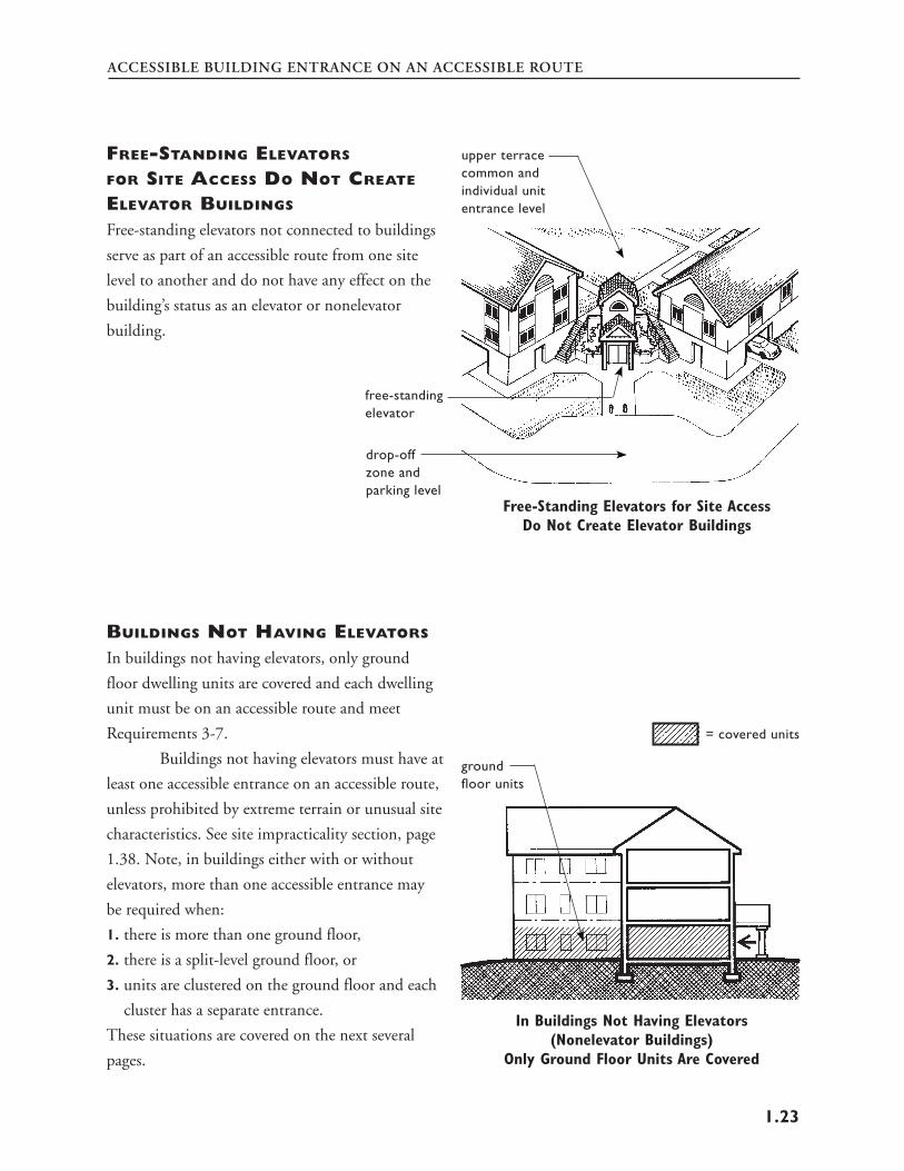
DWELLINGS COVERED
BY THE DESIGN REQUIREMENTS
The design requirements apply to buildings built
for first occupancy after March 13, 1991, which
fall under the definition of “covered multifamily
dwellings.” See page 12 for a discussion of “first
occupancy.” Covered multifamily dwellings are:
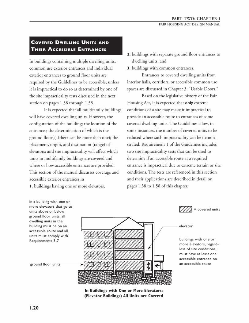
1. all dwelling units in buildings containing four or
more dwelling units if such buildings have one
or more elevators, and
2. all ground floor dwelling units in other
buildings containing four or more units.
To be a covered unit, all of the finished living space
must be on the same floor, that is, be a single-story
unit, such as single-story townhouses, villas, or
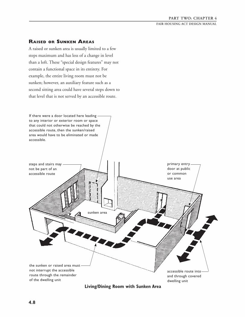
patio apartments. Even though raised and sunken
areas are permissible in covered dwelling units,
there are limitations to their use and they are
discussed in Chapter Four: “Accessible Route Into
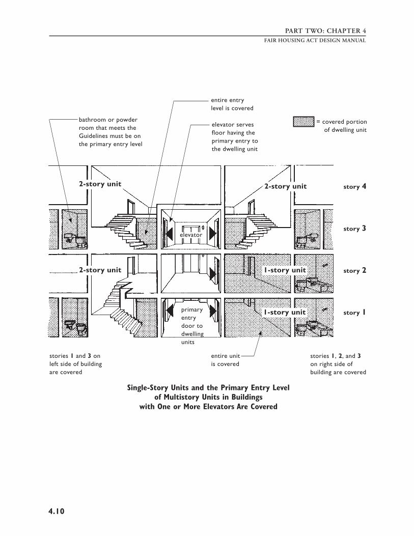
and Through the Covered Unit.” Multistory
dwelling units are not covered by the Guidelines
except when they are located in buildings which
have one or more elevators, in which case, the
primary entry level is covered.
7
4
PART ONE
Dwelling Units in Buildings
with Elevator(s)
As is evident from the preceding discussion, the
Fair Housing Act’s definition of “covered multifam
ily dwellings” distinguishes between buildings with
elevators and buildings without elevators. Thus, if
a building has one or more elevators, all of the
dwelling units in the building are covered.
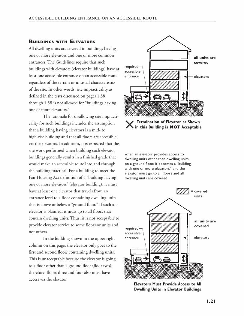
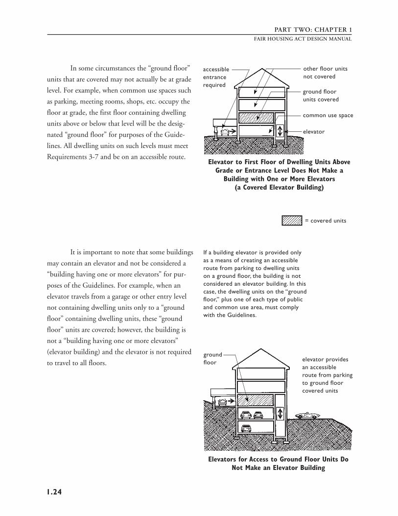
There is one exception to this requirement,
and that is when an elevator is provided only as a
means of creating an accessible route to dwelling
units on a ground floor. In that case, the elevator is
not required to serve dwelling units on floors
which are not ground floors, and the building is
not considered to be a “building with one or more
elevators” that would require all of the dwelling
units to meet the requirements of the Guidelines.
This concept is discussed more fully in Chapter 1:
“Accessible Building Entrance on an Accessible
Route,” starting on page 1.21.
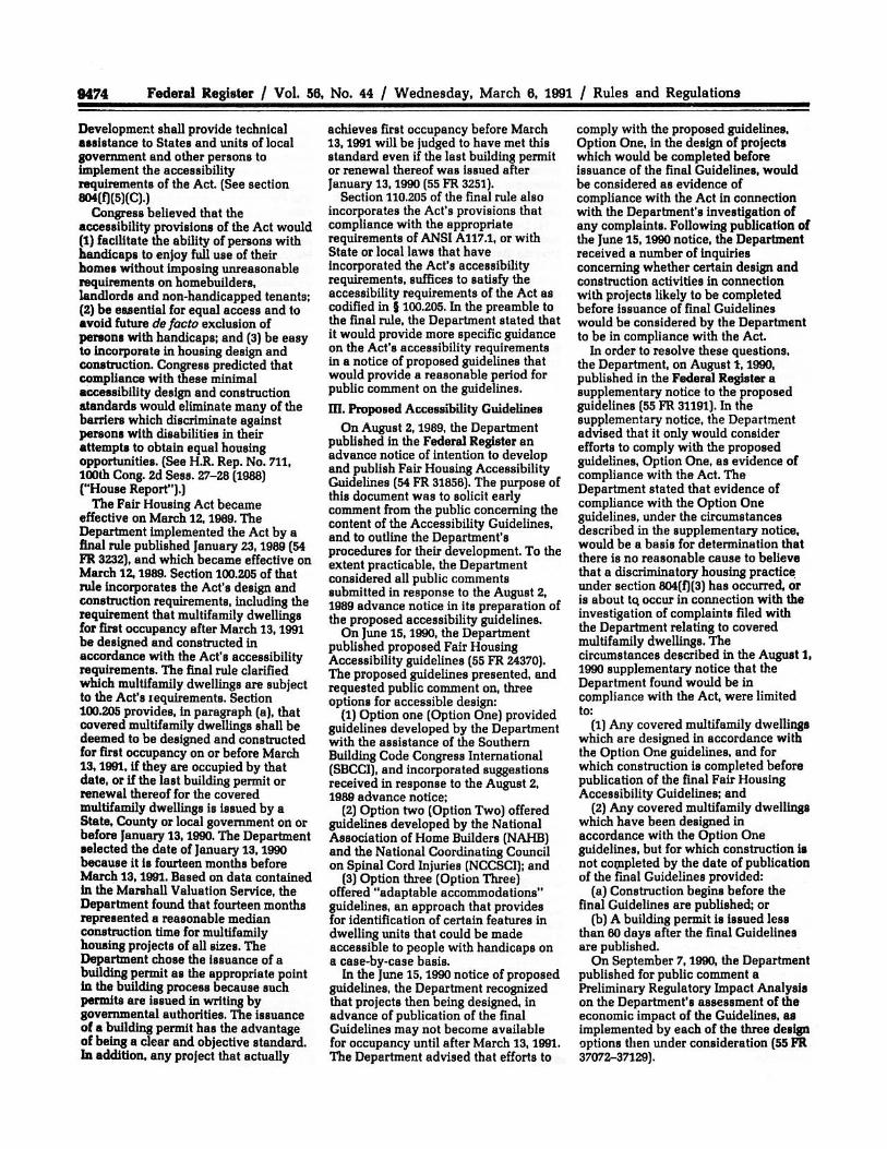
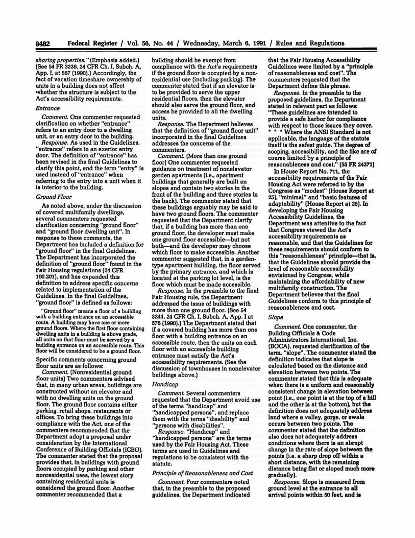
single-story unit (covered)
finished basementwith living space two-story unitsmakes this a two- (not covered)story dwelling unit,thus, it is not covered
Ground Floor Dwelling Units
The ground floor is defined as a floor of a build
ing with a building entrance on an accessible route.
The ground floor may or may not be at grade.
FAIR HOUSING ACT DESIGN MANUAL
elevator
two-story units
one-story units
Buildings with Elevator(s):All Single-Story Units and the Primary Entry
Level of Multistory Units Are Covered
= covered floors
primary entry
Ground Floor Units in Buildings of 4 or More Units Are Covered
= covered unit
8
INTRODUCTION
The definition of ground floor further
provides that where the first floor containing
dwelling units in a building is above grade, all units
on that floor must be served by a building entrance
on an accessible route. This floor will be considered
to be a ground floor.
If more than one story can be designed to
have an accessible entrance on an accessible route,
then each story becomes a ground floor and all
units on those stories are covered. However, the
Fair Housing Act and the Guidelines do not
require that there be more than one ground floor.
See Chapter 1: “Accessible Building Entrance on an
Accessible Route” for more detailed discussion of
covered ground floors.
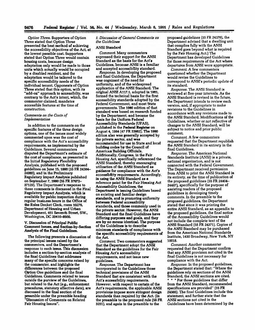
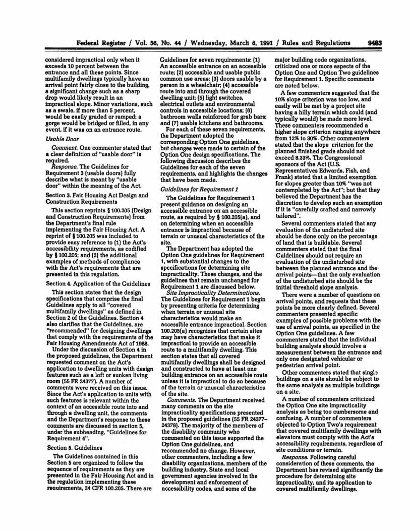
placing shops or garages under multi-
an accessible route via a family housing is a ramp or elevator must design choice and is be provided to the first not dictated by floor of dwelling units extremes of terrain
ground floor with single-story dwelling units
shops or garage
Covered Dwelling Units OverShops and Garages
planned = covered floors grade level
entrance
planned l
entrance
Building Has Two Ground Floors, Each with an Accessible Entrance on an
Accessible Route
grade leve
single-story walk-up units (not covered) single-story
units (covered)
Dwelling Units on the Ground Floor Are Covered (the Guidelines Do Not Require that There Be a Second Ground Floor)
9
PART ONEFAIR HOUSING ACT DESIGN MANUAL
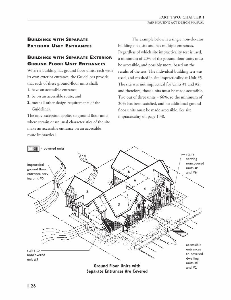
EXAMPLES OF COVERED
MULTIFAMILY DWELLINGS
The Fair Housing Act does not distinguish between
different forms of ownership when determining
whether a unit or building is covered. Condomini
ums are covered by the Fair Housing Act even if
they are pre-sold as a shell and the interior is
designed and constructed by the buyer. All covered
units must comply with the design and construc
tion requirements of the Guidelines. Single-story
townhouses are covered, as are other types of
housing including vacation timeshare units, college
dormitories, apartment housing in private universi
ties, and sleeping accommodations intended for
occupancy as a residence in a shelter.
Continuing care facilities or retirement
communities are covered even when they include
health care, provided the facility includes at least
one building with four or more dwelling units.
Whether a facility is considered a “dwelling”
depends on whether the facility is to be used as a
residence for more than a brief period of time. The
operation of each continuing care facility must be
examined on a case-by-case basis to determine
whether it contains covered multifamily dwellings.
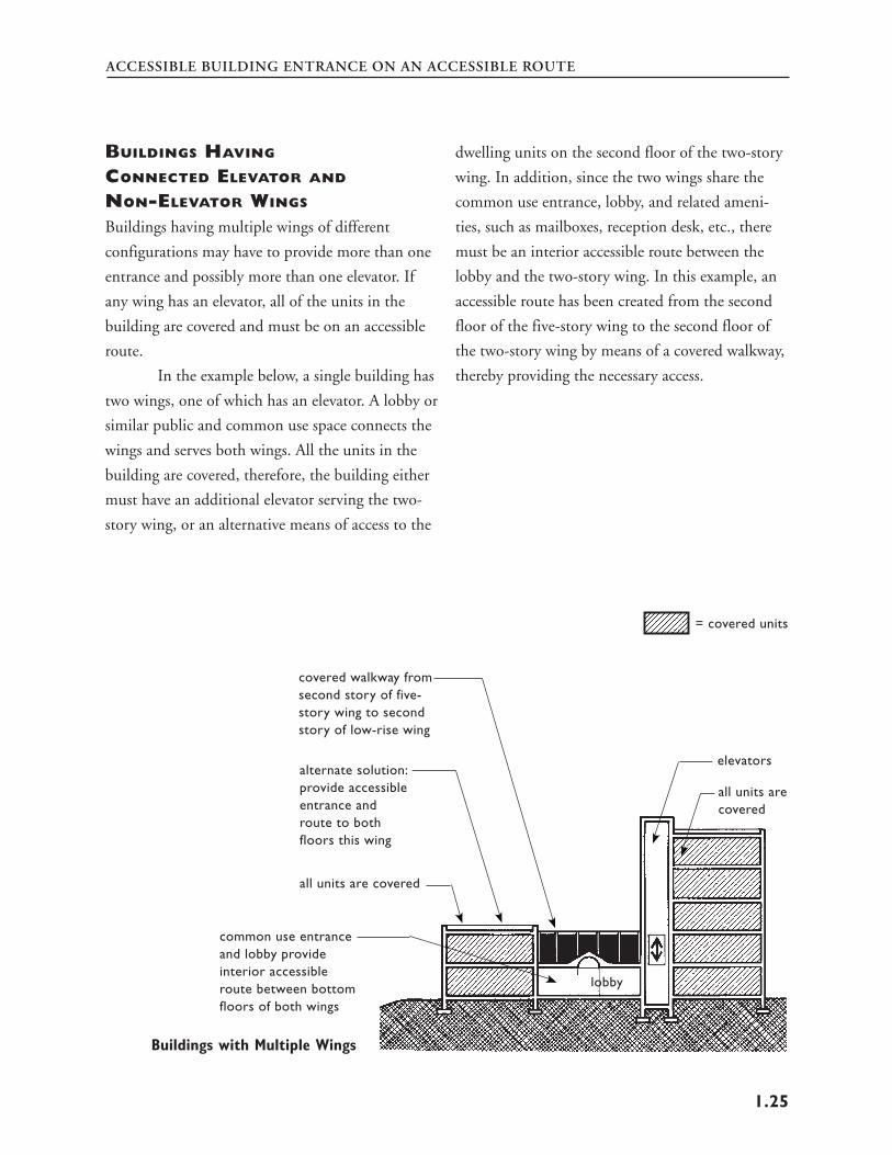
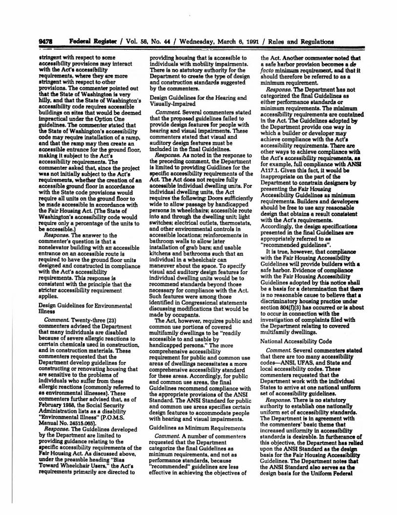
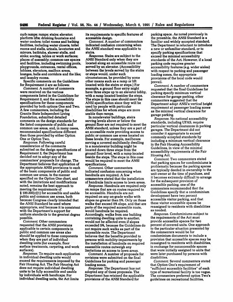
Buildings Separated by Firewalls
or Covered Walkways
Dwellings built within a single structure but
separated by a firewall are treated under the Fair
Housing Act as a single building. For example, a
structure containing two units on each side of a
firewall would not be regarded as four two-unit
buildings (and thus not covered by the Guidelines)
but as a single eight-unit building.
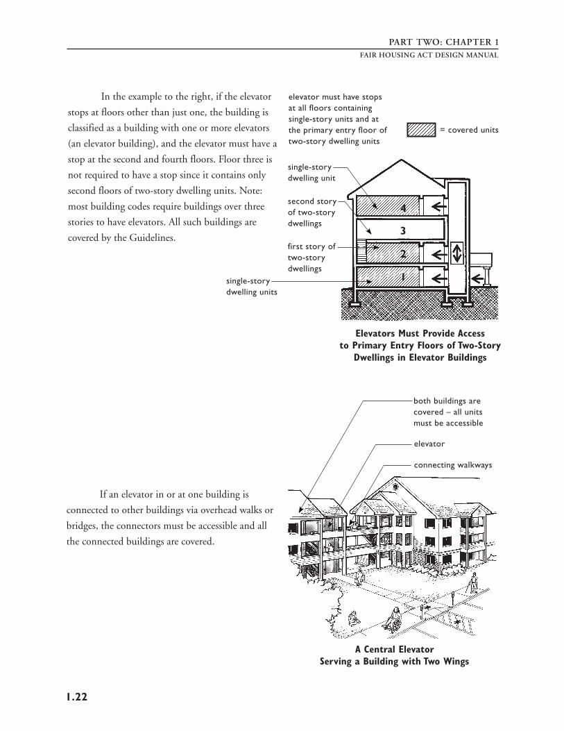
In other situations where the dwelling
units are connected, such as by stairs or a walkway
that is structurally tied to the main body of the
building, for purposes of the Guidelines, they are
considered a single building and ground floor units
in such buildings without elevators are covered.
fire walls
Building with Firewalls Is Treated as a Single Building
stair, overhead walk, and roof
3 units 3 units structurally tied to each building makes this a six-unit single building
For Purposes of the Guidelines, Two Structurally Joined Buildings Are Treated as a Single Building
10
INTRODUCTION
Building Conversions
If a building was used previously for a nonresiden
tial purpose, such as a warehouse, office building,
or school, and is being converted to multifamily
housing, the conversion is not covered. The Fair
Housing Act only applies to covered buildings for
first occupancy after March 13, 1991. The regula
tions define “first occupancy” as “a building that
has never before been used for any purpose.”
See page 12 for additional discussion of “first
occupancy.”
New Construction Behind Old Facade
In cases where the facade of a building is preserved,
but the interior of the building, including all
structural portions of floors and ceilings is re
moved, and a new building is constructed behind
the old facade, the building is considered a new
building for the purposes of the Fair Housing Act.
Thus, it is covered and must comply with the
Guidelines.
Additions to Existing Buildings
When an addition is built as an extension to an
existing building, the addition of four or more
units is regarded as a new building and must meet
the design requirements of the Guidelines.
If any new public and common use spaces are
added, they are required to be accessible. If, for
example, an apartment wing is added to an existing
hotel, the apartments are covered by the Fair
Housing Act.
Housing for Older Persons Is Covered
Housing built specifically for older persons is
exempt from complying with the Fair Housing
Act’s prohibition against discrimination based on
familial status (see 24 CFR 100.303 and 100.304).
However, such housing is still subject to the Fair
Housing Act’s other requirements, including the
design requirements for accessibility.
facade is all
of original construction
that remains new construction
New Construction Behind Old Facade Is Covered
11
PART ONEFAIR HOUSING ACT DESIGN MANUAL
FIRST OCCUPANCY
AFTER MARCH 13, 1991
The Fair Housing Act does not require any renova
tions to existing buildings. Its design requirements
apply to new construction only – to covered
multifamily dwellings that are built for first occu
pancy after March 13, 1991. First occupancy is
defined as “a building that has never before been
used for any purpose.” See also “Definitions Used
in the Guidelines,” page 16.
A building is not subject to the design
requirements of the Fair Housing Act if:
1. it was occupied on or before March 13, 1991,
– or –
2. the last building permit or renewal thereof was
issued by a state, county, or local government on or
before June 15, 1990.
For a building to be considered occupied, the
following criteria must be met:
1. a certificate of occupancy must have been issued,
– and –
2. at least one dwelling unit actually must be
occupied.
a. For a building containing rental units, this
means that a resident has signed a lease and
taken possession of a unit. The resident must
have the legal right to occupy the premises,
but need not have physically moved in yet.
b. For a building containing for-sale units,
this means that a new owner has completed
settlement and taken possession of a unit.
The new owner must have the legal right to
occupy the premises, but need not have
physically moved in yet.
A certificate of occupancy, or the fact that
units are being offered for sale but not yet sold,
would not be an acceptable means of establishing
occupancy. For a project consisting of several
buildings which are constructed in phases spanning
the March 13, 1991 date, first occupancy will be
determined on a building-by-building basis.
12
INTRODUCTION
THE ANSI STANDARD, THE FAIR
HOUSING ACT, AND THE GUIDELINES
The Fair Housing Act requires certain features of
accessible design for covered multifamily dwellings
built for first occupancy after March 13, 1991. The
Act and HUD's implementing regulations, as well
as the final Fair Housing Accessibility Guidelines
(the Guidelines) reference the 1986 ANSI A117.1
American National Standard for Buildings and
Facilities – Providing Accessibility and Usability for
Physically Handicapped People as an acceptable
standard to meet when designing accessible
elements, spaces, and features outside covered
dwelling units.
The level of accessibility required by the
Fair Housing Act is relatively high on the site and
in common use areas where compliance with
much of the ANSI Standard is required. Access
ibility is less stringent within the dwelling units
where only specific features outlined in the Guide
lines are required. In some instances, the specifica
tion is a modification of the related ANSI section,
and in other instances the Guidelines substitute
specifications.
The Guidelines state in the “Purpose”
Section that the Guidelines are to provide technical
guidance on designing dwelling units that are in
compliance with the Fair Housing Act, and are not
mandatory. Rather, the Guidelines provide a safe
harbor for compliance with the accessibility
requirements of the Act.
The “Purpose” Section also states, “Build
ers and developers may choose to depart from these
Guidelines and seek alternate ways to demonstrate
that they have met the requirements of the Fair
Housing Act.” However, it is recommended that,
if a designer or builder chooses to follow an accessi
bility standard other than the 1986 ANSI A117.1
Standard, or a more recent version of the ANSI
A117.1, such as the 1992 CABO/ANSI, that care
be taken to ensure the standard used is at least
equivalent to or stricter than the 1986 ANSI
A117.1 Standard.
Note: Whenever this Manual states the
ANSI Standard or the ANSI A117.1 Standard
“must be followed,” it means the 1986 ANSI
A117.1 Standard or an equivalent or stricter
standard.
13
PART ONE
THE GUIDELINES
The design requirements of the Guidelines to which
new buildings and dwelling units must comply are
presented in abridged form below. Dwelling units
are not subject to these requirements only in the
rare instance where there are extremes of terrain or
unusual characteristics of the site. Such instances
are discussed in detail in Chapter One: “Accessible
Building Entrance on an Accessible Route.”
REQUIREMENT 1
Accessible Building Entrance on an Accessible
Route: Covered multifamily dwellings must have
at least one building entrance on an accessible route,
unless it is impractical to do so because of terrain or
unusual characteristics of the site. For all such
dwellings with a building entrance on an accessible
route the following six requirements apply.
REQUIREMENT 2
Accessible and Usable Public and Common
Use Areas: Public and common use areas must be
readily accessible to and usable by people with
disabilities. See Chapter Two.
REQUIREMENT 3
Usable Doors: All doors designed to allow passage
into and within all premises must be sufficiently
wide to allow passage by persons in wheelchairs. See
Chapter Three.
REQUIREMENT 4
Accessible Route Into and Through the
Covered Dwelling Unit: There must be an
accessible route into and through the dwelling units,
providing access for people with disabilities
throughout the unit. See Chapter Four.
FAIR HOUSING ACT DESIGN MANUAL
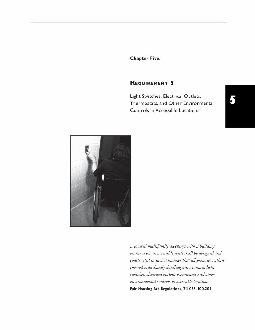
REQUIREMENT 5
Light Switches, Electrical Outlets,
Thermostats and Other Environmental
Controls in Accessible Locations: All premises
within the dwelling units must contain light
switches, electrical outlets, thermostats and other
environmental controls in accessible locations. See
Chapter Five.
REQUIREMENT 6
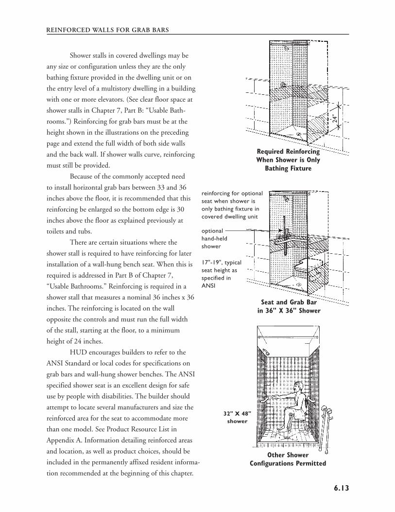
Reinforced Walls for Grab Bars: All premises
within dwelling units must contain reinforcements
in bathroom walls to allow later installation of
grab bars around toilet, tub, shower stall and
shower seat, where such facilities are provided. See
Chapter Six.
REQUIREMENT 7
Usable Kitchens and Bathrooms: Dwelling
units must contain usable kitchens and bathrooms
such that an individual who uses a wheelchair can
maneuver about the space. See Chapter Seven.
14
INTRODUCTION
DEFINITIONS USED
IN THE GUIDELINES
This is the complete list of definitions used in the
Guidelines, excluding a definition for “handicap”
and “controlled substance.” See Appendix B of this
manual for a reprint of the Guidelines, which
contains the complete list. Two additional defini
tions, taken from the regulations and a Guideline
Requirement, are provided below. They are so noted
with the definition.
Accessible
when used with respect to the public and common
use areas of a building containing covered multi
family dwelling units, means that the public or
common use areas of the building can be
approached, entered, and used by individuals with
physical disabilities. The phrase “readily accessible
to and usable by” is synonymous with accessible.
A public or common use area that complies with
the appropriate requirements of ANSI A117.1-
1986, a comparable standard, or these Guidelines is
“accessible” within the meaning of this paragraph.
Accessible route
means a continuous and unobstructed path con
necting accessible elements and spaces in a building
or within a site that can be negotiated by a person
with a severe disability using a wheelchair, and that
is also safe for and usable by people with other
disabilities. Interior accessible routes may include
corridors, floors, ramps, elevators, and lifts. Exterior
accessible routes may include parking access aisles,
curb ramps, walks, ramps, and lifts. A route that
complies with the appropriate requirements of
ANSI A117.1-1986, a comparable standard, or
Requirement 1 of these Guidelines is an “accessible
route.” In the circumstances described in Require
ments 1 and 2, “accessible route” may include
access via a vehicular route.
Adaptable dwelling units
when used with respect to covered multifamily
dwellings, means dwelling units that include the
features of adaptable design specified in 24 CFR
100.205(c) (2)-(3).
ANSI A117.1 - 1986
means the 1986 edition of the American National
Standard for buildings and facilities providing
accessibility and usability for physically disabled
people.
Assistive device
means an aid, tool, or instrument used by a person
with disabilities to assist in activities of daily living.
Examples of assistive devices include tongs, knob-
turners, and oven-rack pusher/pullers.
Bathroom
means a bathroom which includes a water closet
(toilet), lavatory (sink), and bathtub or shower. It
does not include single-fixture facilities or those
with only a water closet and lavatory. It does
include a compartmented bathroom. A compart
mented bathroom is one in which the fixtures are
distributed among interconnected rooms. A
compartmented bathroom is considered a single
unit and is subject to the Act’s requirements for
bathrooms.
15
PART ONE
Building
means a structure, facility, or portion thereof that
contains or serves one or more dwelling units.
Building entrance on an accessible route
means an accessible entrance to a building that is
connected by an accessible route to public trans
portation stops, to parking or passenger loading
zones, or to public streets or sidewalks, if available.
A building entrance that complies with ANSI
A117.1 -1986 (see Requirement 1 of these Guide
lines) or a comparable standard complies with the
requirements of this paragraph.
Clear
means unobstructed.
Common use areas
means rooms, spaces, or elements inside or outside
of a building that are made available for the use of
residents of a building or the guests thereof. These
areas include hallways, lounges, lobbies, laundry
rooms, refuse rooms, mail rooms, recreational
areas, and passageways among and between build
ings. See Requirement 2 of these Guidelines.
Covered multifamily dwellings
or covered multifamily dwellings subject to the Fair
Housing Amendments means buildings consisting
of four or more dwelling units if such buildings
have one or more elevators, and ground floor
dwelling units in other buildings consisting of four
or more dwelling units. Dwelling units within a
single structure separated by firewalls do not
constitute separate buildings.
FAIR HOUSING ACT DESIGN MANUAL
Dwelling unit
means a single unit of residence for a household of
one or more persons. Examples of dwelling units
covered by these Guidelines include: condomini
ums, an apartment unit within an apartment
building, and other types of dwellings in which
sleeping accommodations are provided but toileting
or cooking facilities are shared by occupants of
more than one room or portion of the dwelling.
Examples of the latter include dormitory rooms and
sleeping accommodations in shelters intended for
occupancy as a residence for homeless persons.
Entrance
means any exterior access point to a building or
portion of a building used by residents for the
purpose of entering. For purposes of these Guide
lines, an “entrance” does not include a door to a
loading dock or a door used primarily as a service
entrance, even if nondisabled residents occasionally
use that door to enter.
Finished grade
means the ground surface of the site after all
construction, levelling, grading, and development
has been completed.
First occupancy
means a building that has never before been used
for any purpose. (Definition found in regulations
at 24 CFR 100.201)
16
INTRODUCTION
Ground Floor
means a floor of a building with a building en
trance on an accessible route. A building may have
one or more ground floors. Where the first floor
containing dwelling units is above grade, all units
on that floor must be served by a building entrance
on an accessible route. This floor will be considered
a ground floor.
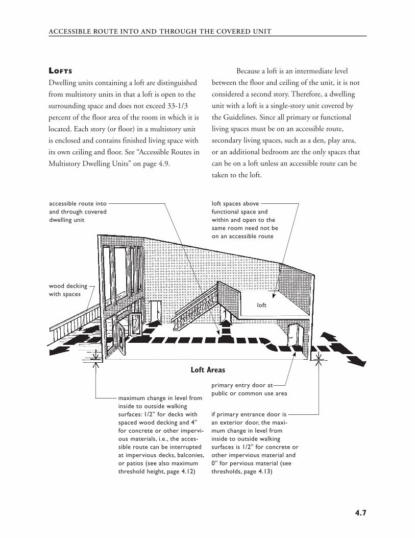
Loft
means an intermediate level between the floor and
ceiling of any story, located within a room or
rooms of a dwelling.
Multistory dwelling unit
means a dwelling unit with finished living space
located on one floor and the floor or floors imme
diately above or below it.
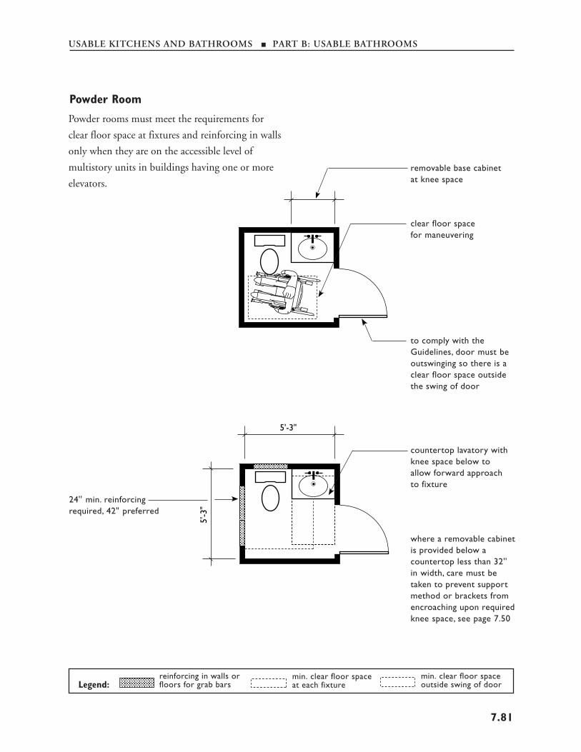
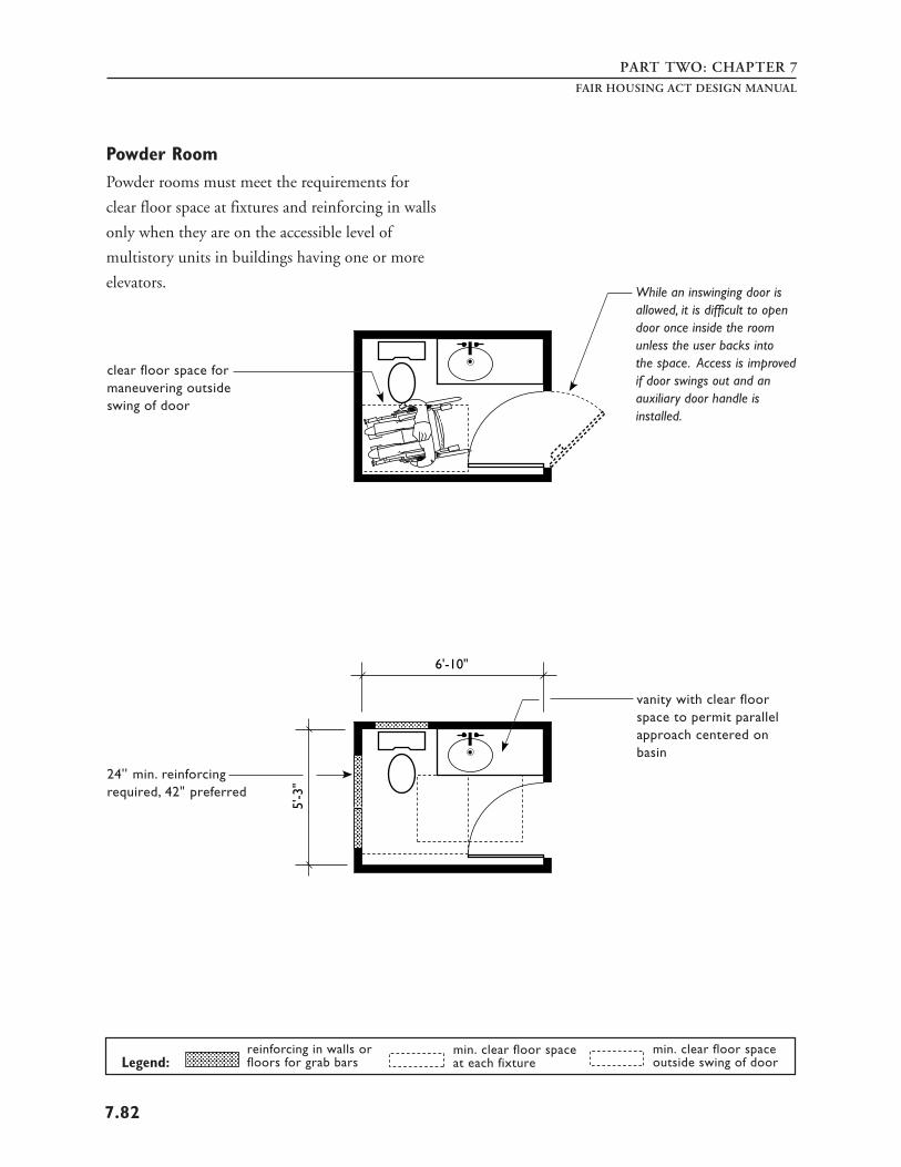
Powder room
A room containing a toilet and a sink. (Definition
found in Requirement 6 of the Guidelines.)
Public use areas
means interior or exterior rooms or spaces of a
building that are made available to the general
public. Public use may be provided at a building
that is privately or publicly owned.
Single-story dwelling unit
means a dwelling unit with all finished living space
located on one floor.
Site
means a parcel of land bounded by a property line
or a designated portion of a public right of way.
Slope
means the relative steepness of the land between
two points and is calculated as follows: The dis
tance and elevation between the two points (e.g.,
an entrance and a passenger loading zone) are
determined from a topographical map. The differ
ence in elevation is divided by the distance and that
fraction is multiplied by 100 to obtain a percentage
slope figure. For example, if a principal entrance is
ten feet from a passenger loading zone, and the
principal entrance is raised one foot higher than
the passenger loading zone, then the slope is
1/10 x 100 = 10%.
Story
means that portion of a dwelling unit between
the upper surface of any floor and the upper
surface of the floor next above, or the roof of
the unit. Within the context of dwelling units,
the terms “story” and “floor” are synonymous.
Undisturbed site
means the site before any construction, levelling,
grading, or development associated with the
current project.
Vehicular or pedestrian arrival points
means public or resident parking areas, public
transportation stops, passenger loading zones, and
public streets or sidewalks.
Vehicular route
means a route intended for vehicular traffic, such as
a street, driveway, or parking lot.
17
PART ONEFAIR HOUSING ACT DESIGN MANUAL
DISABILITY TYPES AND
IMPLICATIONS FOR DESIGN
TYPES OF DISABILITIES
Most people will, at some time during their life,
have a disability, either temporary or permanent,
which limits their ability to move around in and
use the built environment. In fact, more than one
in five Americans aged 15 and over have some type
of disability; problems with walking and lifting are
the most common. Not until fairly recently have
the needs of people with disabilities been given
adequate attention. The passage of the Fair Hous
ing Act is another step in the process to create a
built environment where people with disabilities
can move freely in society as do persons who have
no disability.
According to the “Statistical Report: the
Status of People with Disabilities,” compiled by the
President’s Committee on Employment of People
with Disabilities, published in 19945 :
• 48.9 million Americans are persons with
disabilities;
• 32 million Americans are age 65 or over; • 3.3 million Americans are 85 and older, and
this number is projected to grow by 100%, to
over 6 million by 2010; • 70% of all Americans will, at some time in
their lives, have a temporary or permanent
disability that makes stair climbing impossible; • 8,000 people survive traumatic spinal cord
injuries each year, returning to homes that are
inaccessible; • 17 million Americans have serious hearing
disabilities;
• 8.1 million Americans have vision disabilities; • 27 million Americans have heart disease and
reduced or limited mobility.
There are hundreds of different disabilities
and they manifest themselves in varying degrees.
One person may have multiple disabilities while
another may have a disability whose symptoms
fluctuate. Most standards and design criteria are
based on the needs of people defined by one of the
following four general categories:
1. MOBILITY DISABILITIES
This category includes people who use wheelchairs
and those who use other mobility aids.
Wheelchair Users
People with severe mobility disabilities use either a
power-driven or manually operated wheelchair or,
the more recent development, the three-wheeled
cart or scooter to maneuver through the environ
ment. People who use wheelchairs have some of the
most obvious access problems. They include
maneuvering through narrow spaces, going up or
down steep paths, moving over rough or uneven
surfaces, making use of toilet and bathing facilities,
reaching and seeing items placed at conventional
heights, and negotiating steps or changes in level at
the entrance to a dwelling unit.
The design and construction requirements
of the Fair Housing Act and the Guidelines focus
primarily on the spatial needs of people who use
wheelchairs because those needs are met more
easily in the initial construction phase of a building
project. This section provides basic information on
the spatial requirements for an average seated adult
Based on the census report Americans With Disabilities 1991/1992, published January 1994
18
5
INTRODUCTION
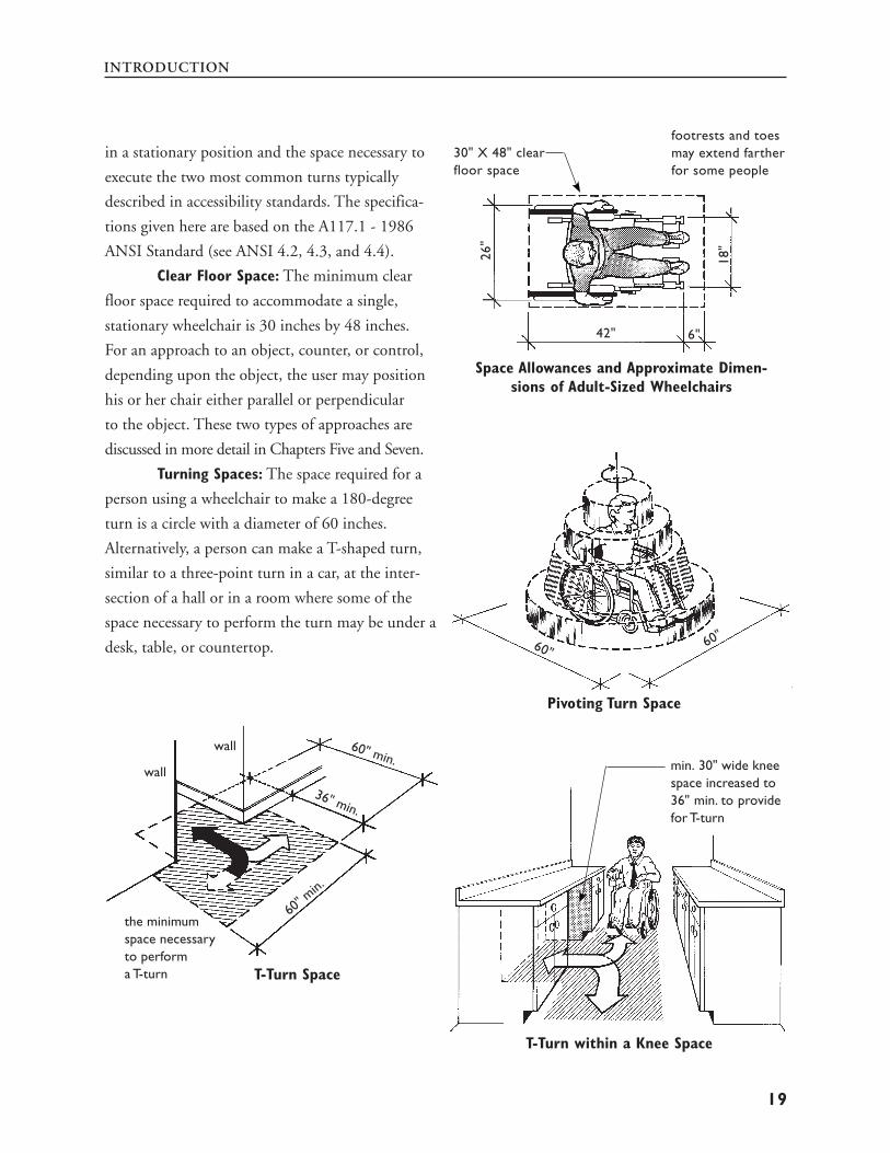
footrests and toes in a stationary position and the space necessary to 30" X 48" clear may extend farther
floor space
6"42"
26"
18"
for some people execute the two most common turns typically
described in accessibility standards. The specifica
tions given here are based on the A117.1 - 1986
ANSI Standard (see ANSI 4.2, 4.3, and 4.4).
Clear Floor Space: The minimum clear
floor space required to accommodate a single,
stationary wheelchair is 30 inches by 48 inches.
For an approach to an object, counter, or control, Space Allowances and Approximate Dimen
sions of Adult-Sized Wheelchairs depending upon the object, the user may position
his or her chair either parallel or perpendicular
to the object. These two types of approaches are
discussed in more detail in Chapters Five and Seven.
Turning Spaces: The space required for a
person using a wheelchair to make a 180-degree
turn is a circle with a diameter of 60 inches.
Alternatively, a person can make a T-shaped turn,
similar to a three-point turn in a car, at the inter
section of a hall or in a room where some of the
space necessary to perform the turn may be under a
desk, table, or countertop. 60"60"
Pivoting Turn Space
wall
wall
60" min.
36" min.
60" m
in.
the minimum space necessary to perform
min. 30" wide knee
a T-turn T-Turn Space
space increased to 36" min. to provide for T-turn
T-Turn within a Knee Space
19
PART ONEFAIR HOUSING ACT DESIGN MANUAL
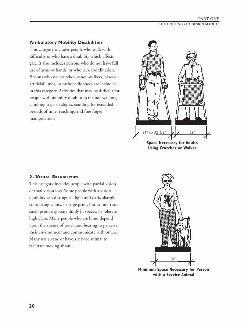
Ambulatory Mobility Disabilities
This category includes people who walk with
difficulty or who have a disability which affects
gait. It also includes persons who do not have full
use of arms or hands, or who lack coordination.
Persons who use crutches, canes, walkers, braces,
artificial limbs, or orthopedic shoes are included
in this category. Activities that may be difficult for
people with mobility disabilities include walking,
climbing steps or slopes, standing for extended
periods of time, reaching, and fine finger
manipulation.
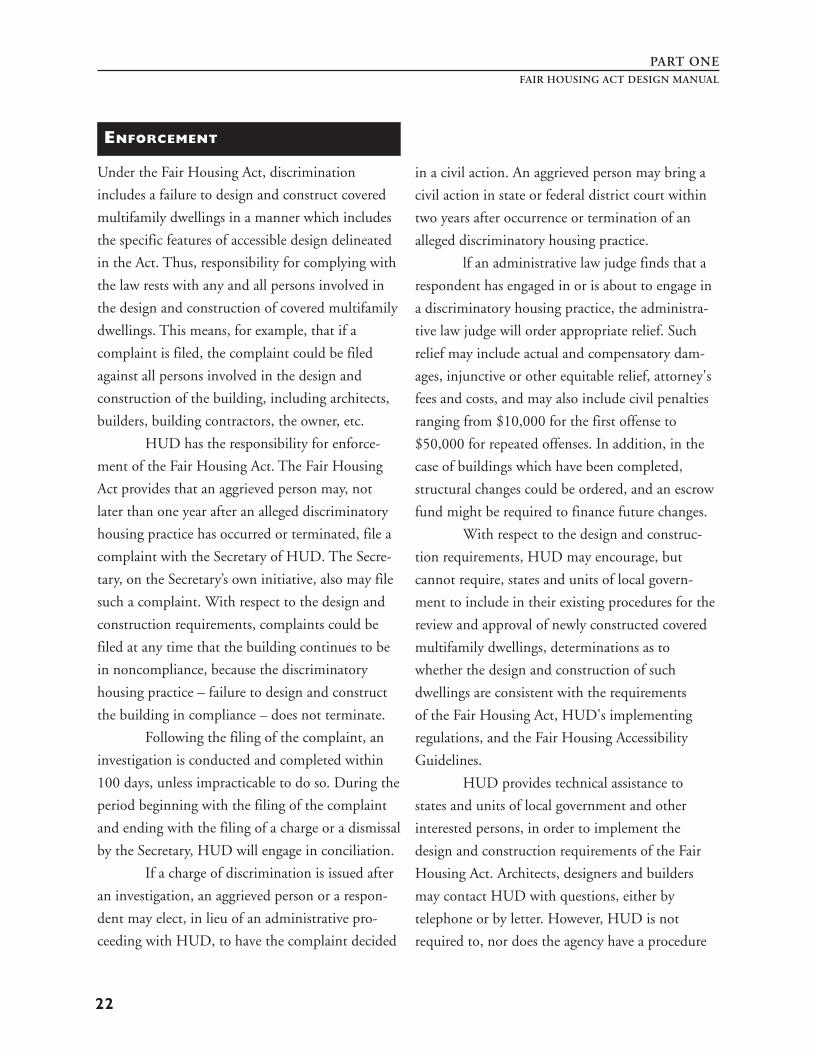
2. VISUAL DISABILITIES
This category includes people with partial vision
or total vision loss. Some people with a vision
disability can distinguish light and dark, sharply
contrasting colors, or large print, but cannot read
small print, negotiate dimly lit spaces, or tolerate
high glare. Many people who are blind depend
upon their sense of touch and hearing to perceive
their environment and communicate with others.
Many use a cane or have a service animal to
facilitate moving about.
31" to 32-1/2" 28"
Space Necessary for Adults Using Crutches or Walker
32"
Minimum Space Necessary for Person with a Service Animal
20
INTRODUCTION
3. HEARING DISABILITIES
People with partial hearing often use a combina
tion of speech reading and hearing aids which
amplify the available sounds. Echo, reverberation,
and extraneous background noise can distort
hearing aid transmission. People who are deaf and
who rely on lip reading for information must be
able to see clearly the face of the individual who is
speaking. Those who use sign language to commu
nicate also may be adversely affected by poor
lighting. People who are hard of hearing or deaf
may have difficulty understanding oral communi
cation and receiving notification by equipment
that is exclusively auditory such as telephones, fire
alarms, public address systems, etc.
4. COGNITIVE DISABILITIES
AND OTHER HIDDEN CONDITIONS
People with cognitive and learning disabilities may
have difficulty using facilities, particularly where
the signage system is unclear or complicated. In
addition to people with permanent disabilities,
there are others who may have a temporary condi
tion which affects their usual abilities. Broken
bones, illness, trauma, or surgery – all may affect a
person’s use of the built environment for a short
time. Frequently, people have diseases of the heart
or lungs, neurological diseases with resulting lack
of coordination, arthritis, or rheumatism that may
reduce physical stamina or cause pain. Reduction
in overall ability is also experienced by many
people as they age. People of extreme size or weight
often need special accommodation as well.
21
PART ONEFAIR HOUSING ACT DESIGN MANUAL
ENFORCEMENT
Under the Fair Housing Act, discrimination in a civil action. An aggrieved person may bring a
includes a failure to design and construct covered civil action in state or federal district court within
multifamily dwellings in a manner which includes two years after occurrence or termination of an
the specific features of accessible design delineated alleged discriminatory housing practice.
in the Act. Thus, responsibility for complying with lf an administrative law judge finds that a
the law rests with any and all persons involved in respondent has engaged in or is about to engage in
the design and construction of covered multifamily a discriminatory housing practice, the administra
dwellings. This means, for example, that if a tive law judge will order appropriate relief. Such
complaint is filed, the complaint could be filed relief may include actual and compensatory dam-
against all persons involved in the design and ages, injunctive or other equitable relief, attorney's
construction of the building, including architects, fees and costs, and may also include civil penalties
builders, building contractors, the owner, etc. ranging from $10,000 for the first offense to
HUD has the responsibility for enforce- $50,000 for repeated offenses. In addition, in the
ment of the Fair Housing Act. The Fair Housing case of buildings which have been completed,
Act provides that an aggrieved person may, not structural changes could be ordered, and an escrow
later than one year after an alleged discriminatory fund might be required to finance future changes.
housing practice has occurred or terminated, file a With respect to the design and construc
complaint with the Secretary of HUD. The Secre tion requirements, HUD may encourage, but
tary, on the Secretary’s own initiative, also may file cannot require, states and units of local govern-
such a complaint. With respect to the design and ment to include in their existing procedures for the
construction requirements, complaints could be review and approval of newly constructed covered
filed at any time that the building continues to be multifamily dwellings, determinations as to
in noncompliance, because the discriminatory whether the design and construction of such
housing practice – failure to design and construct dwellings are consistent with the requirements
the building in compliance – does not terminate. of the Fair Housing Act, HUD's implementing
Following the filing of the complaint, an regulations, and the Fair Housing Accessibility
investigation is conducted and completed within Guidelines.
100 days, unless impracticable to do so. During the HUD provides technical assistance to
period beginning with the filing of the complaint states and units of local government and other
and ending with the filing of a charge or a dismissal interested persons, in order to implement the
by the Secretary, HUD will engage in conciliation. design and construction requirements of the Fair
If a charge of discrimination is issued after Housing Act. Architects, designers and builders
an investigation, an aggrieved person or a respon may contact HUD with questions, either by
dent may elect, in lieu of an administrative pro- telephone or by letter. However, HUD is not
ceeding with HUD, to have the complaint decided required to, nor does the agency have a procedure
22
INTRODUCTION
for, review and approval of building plans to
determine if they are in compliance. Technical
assistance provided by HUD serves only as general
interpretation of law and regulations and is not
binding on the agency with respect to a specific case.
Some states have incorporated the require
ments of the Fair Housing Act into their state laws.
How this is done may differ from state to state.
Some states, for example, have included the design
and construction requirements as a part of the state
law and simply incorporated HUD’s Fair Housing
Accessibility Guidelines by reference. Other states
have drafted their own language to implement the
design and construction requirements of the Fair
Housing Act into the state building code. States
which have incorporated the requirements of the
Fair Housing Act into their state laws enforce those
laws independently of the federal government.
However, it should be noted that it is the state law
that is being enforced. Such enforcement will not
preclude any individual from exercising his or her
right to file a complaint with HUD under the Fair
Housing Act, or from filing a private lawsuit; nor
does it preclude HUD from conducting a
Secretary-initiated complaint.
The Fair Housing Act does not invalidate
or limit any law of a state or local government that
requires dwellings to be designed and constructed
in a manner that affords persons with disabilities
greater accessibility than the requirements of the
Fair Housing Act. Likewise, the Fair Housing Act
does not invalidate or replace other federal laws
which require greater accessibility in certain
housing, such as Section 504 of the Rehabilitation
Act of 1973 or the Architectural Barriers Act
of 1968.
The following is a list of HUD enforce
ment offices. Architects, builders and other users of
this manual are encouraged to contact these and
other HUD Fair Housing field offices for technical
assistance as needed.
New England
U.S. Department of Housing
and Urban Development
Thomas P. O’Neill, Jr. Federal Building
10 Causeway Street, Room 308
Boston, Massachusetts 02222-1092
(617) 994-8300
Connecticut, Maine, Massachusetts,
New Hampshire, Rhode Island,Vermont
New York/New Jersey
U.S. Department of Housing
and Urban Development
26 Federal Plaza
New York, New York 10278-0068
(212) 264-1290
New Jersey, New York
Mid-Atlantic
U.S. Department of Housing
and Urban Development
The Wanamaker Building
100 Penn Square East
Philadelphia, Pennsylvania 19106-3392
(215) 656-0647
Delaware, District of Columbia, Maryland,
Pennsylvania, Virginia,West Virginia
23
PART ONE
Southeast/Caribbean
U.S. Department of Housing
and Urban Development
Five Points Plaza
40 Marietta Street
Atlanta, Georgia 30303-3388
(404) 331-5140
Alabama, Florida, Georgia, Kentucky,
Mississippi, North Carolina, South Carolina,
Tennessee, Puerto Rico,Virgin Islands
Midwest
U.S. Department of Housing
and Urban Development
77 West Jackson Boulevard
Chicago, Illinois 60604-3507
(312) 353-7776
Illinois, Indiana, Minnesota, Michigan,
Ohio, Wisconsin
Southwest
U.S. Department of Housing
and Urban Development
801 North Cherry Street
Fort Worth, Texas 76113-2905
(817) 978-5900
Arkansas, Louisiana, New Mexico,
Oklahoma, Texas
Great Plains
U.S. Department of Housing
and Urban Development
Gateway Tower II, 400 State Avenue
Kansas City, Kansas 66101-2406
(913) 551-6958
Iowa, Kansas, Missouri, Nebraska
FAIR HOUSING ACT DESIGN MANUAL
Rocky Mountain
U.S. Department of Housing
and Urban Development
First Interstate Tower North
633 17th Street
Denver, Colorado 80202-2349
(303) 672-5434
Colorado, Montana, North Dakota, South
Dakota, Utah,Wyoming
Pacific/Hawaii
U.S. Department of Housing
and Urban Development
Phillip Burton Federal Building
450 Golden Gate Avenue
P.O. Box 36003
San Francisco, California 94102-3448
(415) 436-6569
Arizona, California, Hawaii, Nevada, Guam,
American Samoa
Northwest/Alaska
U.S. Department of Housing
and Urban Development
Federal Office Building
909 First Avenue, Suite 200
Seattle, Washington 98104-1000
(206) 220-5170
Alaska, Idaho, Oregon,Washington
24
DESIGN R GUIDELINES
Part Two
EQUIREMENTS OF THE
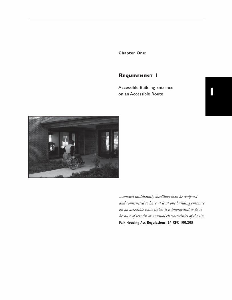
Chapter One:
REQUIREMENT 1
Accessible Building Entrance on an Accessible Route
...covered multifamily dwellings shall be designed
and constructed to have at least one building entrance
on an accessible route unless it is impractical to do so
because of terrain or unusual characteristics of the site.
Fair Housing Act Regulations, 24 CFR 100.205
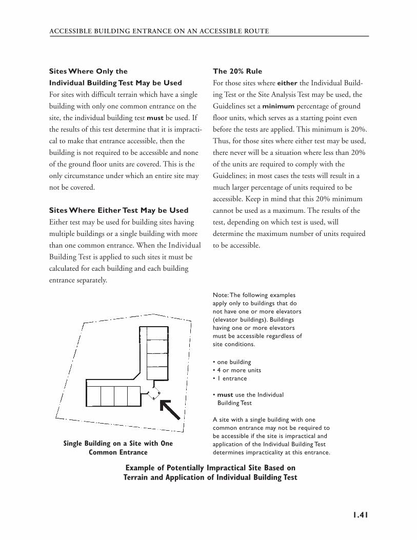
1
PART TWO: CHAPTER 1FAIR HOUSING ACT DESIGN MANUAL
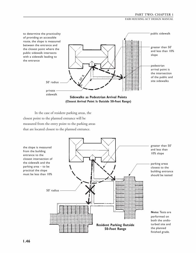
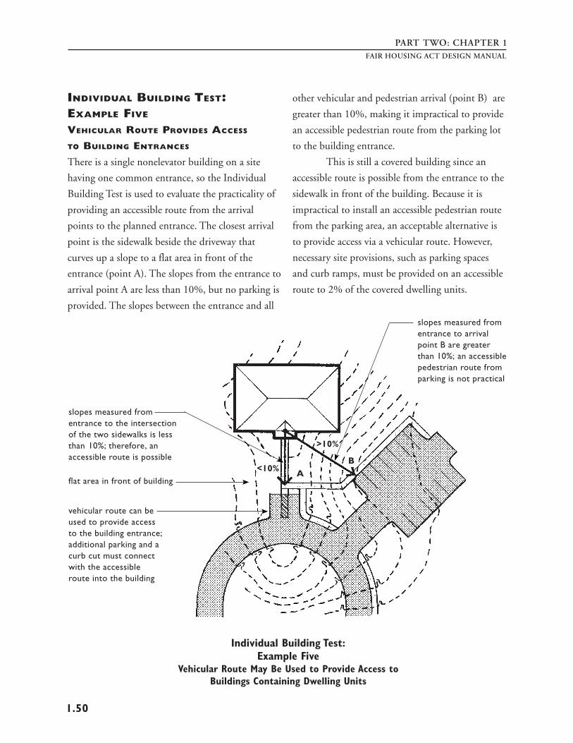
Definitions from the Guidelines
Accessible route. A continuous unobstructed path connecting accessible elements and spaces in a building or within a site that can be negotiated by a person with a severe disability using a wheelchair, and that is also safe for and usable by people with other disabilities. Interior accessible routes may include corridors, floors, ramps, elevators and lifts. Exterior accessible routes may include parking access aisles, curb ramps, walks, ramps, and lifts. A route that complies with the appropriate requirements of ANSI A117.1 – 1986, a comparable standard, or Section 5, Requirement 1 of these guidelines is an “accessible route.” In the circumstances described in Section, 5, Requirements 1 and 2, “accessible route” may include access via a vehicular route.
Building. A structure, facility or portion thereof that contains or serves one or more dwelling units.
Building entrance on an accessible route. An accessible entrance to a building that is connected by an accessible route to public transportation stops, to parking or passenger loading zones, or to public streets or sidewalks, if available. A building entrance that complies with ANSI A117.1 – 1986 or a comparable standard complies with the requirements of this paragraph.
Entrance. Any exterior access point to a building or portion of a building used by residents for the purpose of entering. For purposes of these guidelines, an “entrance” does not include a door to a loading dock
or a door used primarily as a service entrance, even if nonhandicapped residents occasionally use that door to enter.
Finished grade. The ground surface of the site after all construction, levelling, grading, and development has been completed.
Site. A parcel of land bounded by a property line or a designated portion of a public right of way.
Slope. The relative steepness of the land between two points and calculated as follows: The distance and elevation between the two points (e.g., an entrance and a passenger loading zone) are determined from a topographical map. The difference in elevation is divided by the distance and that fraction is multiplied by 100 to obtain a percentage slope figure. For example, if a principal entrance is ten feet from a passenger zone, and the principal entrance is raised one foot higher than the passenger loading zone, then the slope is 1/10 x 100 = 10%.
Undisturbed site. The site before any construction, levelling, grading, or development associated with the current project.
Vehicular or pedestrian arrival points. Public or resident parking areas, public transportation stops, passenger loading zones, and public streets or sidewalks.
Vehicular route. A route intended for vehicular traffic, such as a street, driveway, or parking lot.
1.2
ACCESSIBLE BUILDING ENTRANCE ON AN ACCESSIBLE ROUTE
INTRODUCTION
The Fair Housing Accessibility Guidelines (the
Guidelines) define covered multifamily dwellings as
1. those buildings consisting of four or more units
if such buildings have one or more elevators and
2. ground floor units in other buildings having four
or more units. The Guidelines do not specify the
total number of entrances a building must have nor
where they must be positioned. However, the
Guidelines do stipulate that each covered building
on a site must have at least one accessible entrance
on an accessible route. It is expected that most
sites can and should be made accessible, i.e., an
accessible route can be provided to entrances of
covered dwellings; therefore, it is also expected that
covered dwelling units will be provided on all
building sites, including those where steep slopes,
rock outcroppings, marshy areas, and similar
conditions exist.
The requirements of the Fair Housing Act
are outlined in the Act itself and in the implement
ing regulations issued by the U.S. Department of
Housing and Urban Development (HUD). Section
100.205 (a) of these regulations states: “Covered
multifamily dwellings for first occupancy after
March 13, 1991, shall be designed and constructed
to have at least one building entrance on an
accessible route unless it is impractical to do so
because of the terrain or unusual characteristics of
the site.”
Requirement 1 of the Guidelines presents
guidance on designing an accessible building
entrance on an accessible route. Requirement 1 also
provides tests to assist a developer of buildings that
do not have one or more elevators to determine
when an accessible entrance is impractical because
of extreme terrain or unusual characteristics of the
site. See impracticality tests pages 1.40 through
1.55. Units where entrances are impractical do not
have to meet the other design requirements; the
tests, therefore, can alter the number of units on a
site that must comply.
The language of the Fair Housing Act itself
does not provide an exception for site impracticality;
however, as HUD notes in the preamble to its
regulations, “the legislative history makes it clear
that Congress was ‘sensitive to the possibility that
certain natural terrain may pose unique building
problems.’”6 In applying the site impracticality tests,
architects and builders should keep in mind that in
enforcement proceedings under the Fair Housing
Act, it is the person(s) who designed and con
structed the building(s) who has the burden of
establishing that site impracticality existed.
Accessible routes and accessible entrances
may occur in the course of any design project. They
also may not occur and be expensive to include later
if a careful approach to site design is not conducted.
Deliberate manipulation of the grade to avoid the
requirements of the Fair Housing Act is regarded as
a discriminatory housing practice and must be
avoided. This chapter offers methods and strategies
to assist designers and builders to more efficiently
provide accessible entrances and routes for all sites.
6House Report No. 100-711, page 27
1.3
PART TWO: CHAPTER 1FAIR HOUSING ACT DESIGN MANUAL
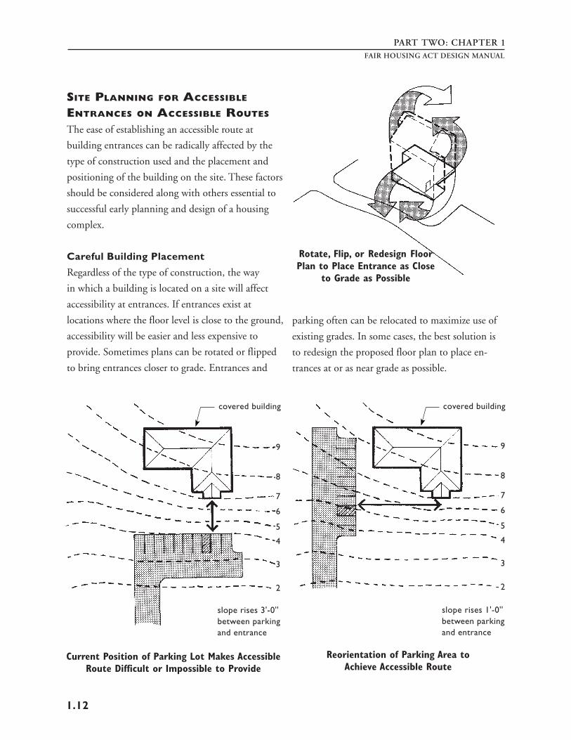
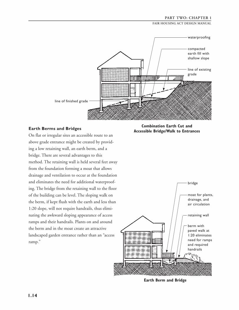
EARLY PLANNING FOR
ACCESSIBLE ROUTES AT ENTRANCES
The language of the Fair Housing Act requires
covered multifamily dwellings to be designed and
constructed in a manner that incorporates certain
features of accessible and adaptable design. The Act
specifically includes the design process, thereby
recognizing that changes will need to be made in
the way buildings are designed in order to assure
accessibility.
Planning for accessibility should be an
integral part of the design process in multifamily
housing developments. This is particularly crucial
in the early stages of planning when major deci
sions are being made about the overall design of
the site. The location and orientation of buildings,
parking areas, loading zones, and other elements
have a major impact on the ease with which
accessibility can be achieved in a finished develop
ment. This is especially important on sloping sites
where careful initial planning can eliminate the
need for major earthwork and the construction of
elaborate ramps, bridges, lifts, or elevators to
provide accessibility.
Attempts should be made to set the
entrance floor levels of buildings at or close to
ground levels to eliminate or minimize changes in
level that may require steps or ramps. Often this
may be accomplished by making use of fill dirt
which has been excavated from other parts of the
building site to alter the ground levels at appropri
ate places.
Since people generally arrive at buildings
by a private car, bus, or taxi, the location of vehicle
arrival points is critical. Passenger drop-off points
and parking areas for people with disabilities
should be located close to building entrances and at
levels which do not necessitate climbing steep
slopes to reach the entrance floor level.
The path of travel to and placement of site
amenities, such as outside mailboxes, refuse dis
posal areas, swimming pools, clubhouses, and
sports facilities should be given careful consider
ation early in the planning process. The intent of
the Fair Housing Act is that people with disabilities
be able to reach and use such amenities.
In this manual, the ANSI Standard A117.1
- 1986 is referenced as the accessibility standard for
compliance in much of public and common use
space of multifamily housing developments. The
Guidelines themselves cite the ANSI A117.1
1986 Standard (the American National Standard for
Buildings and Facilities – Providing Accessibility and
Usability for Physically Handicapped People).
Although referenced, the ANSI specifications are
not mandated. Any ANSI citation in this manual
refers to the 1986 ANSI A117.1 Standard and
should be understood to mean that compliance
with ANSI or any other similar accessibility
standard that is equal to or more stringent than the
ANSI A117.1 (1986) Standard would fulfill the
requirements of the accessibility provisions of the
Fair Housing Act.
1.4
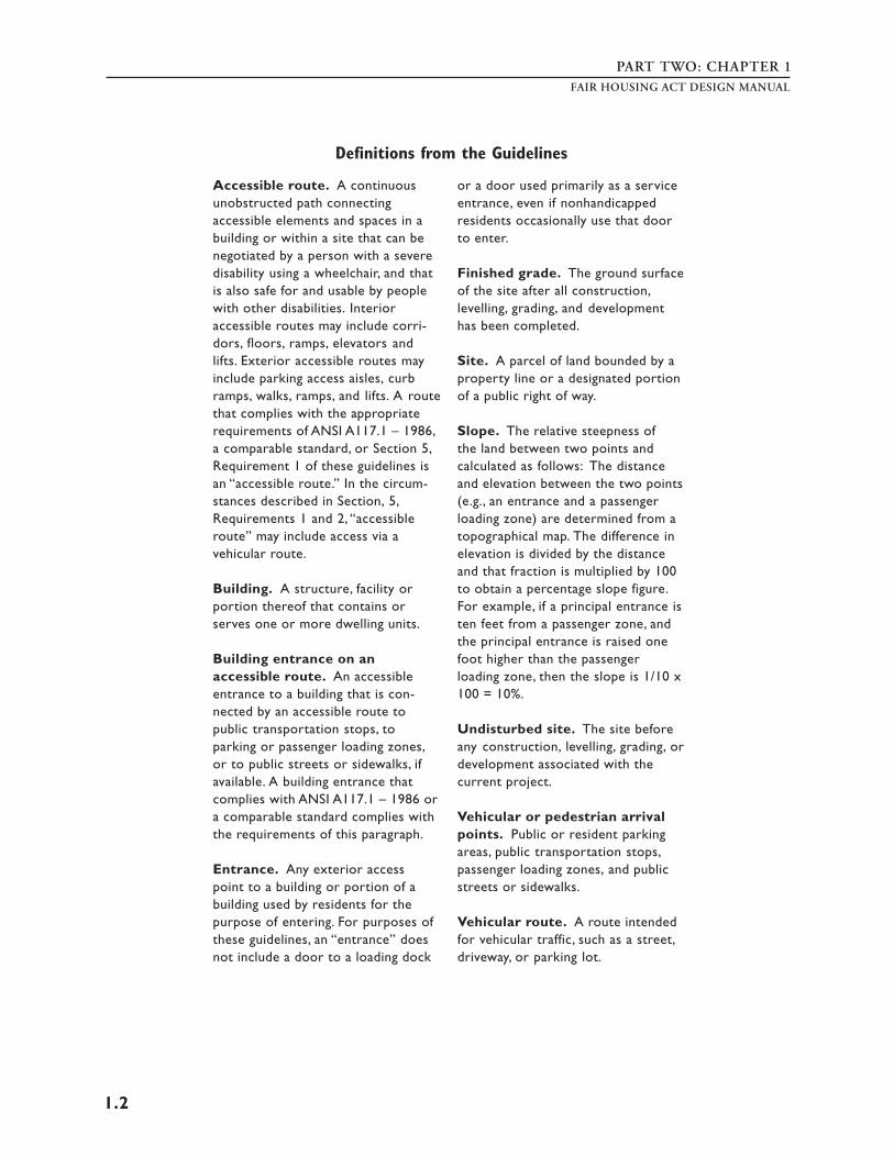
ACCESSIBLE BUILDING ENTRANCE ON AN ACCESSIBLE ROUTE
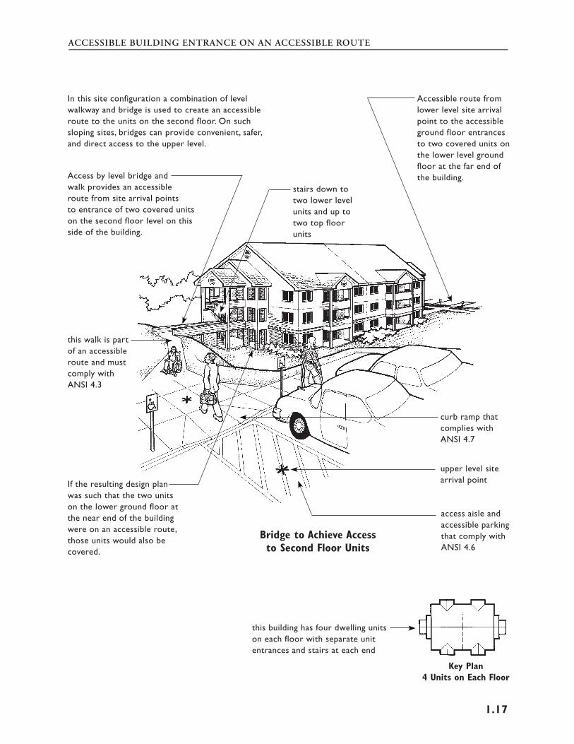
impractical based
in buildings with
accessible pedestrian
with site facilities
designated accessible
in buildings without
an accessible pedes
and accessible parking
a portion or all of
entrances may be
elevators all dwelling units are covered
route connecting covered dwellings
parking spaces for residents and visitors
elevators all ground floor dwelling units
because tennis courts are not reachable on
trian route, a road
must be provided
are covered
certain building
inaccessible if
on site tests
accessible routes between buildings with covered dwelling units not required, but are recommended
building entrances must be connected by an accessible route to public transportation stops within the boundary of the site
the jogging trail must be accessible unless impractical due to extremes of terrain
accessible community center or clubhouse on an accessible route
accessible commonthe swimming pool, picnic area,
and playground are site amenities building
and must be reachable by an entrance
accessible route; in this example, a road and accessible parking are Careful Site Analysis and Building Placement in the not required since there is an Planning Stage of a Housing Development Makes accessible pedestrian route Accessible Entrances Easier to Provide
1.5
PART TWO: CHAPTER 1
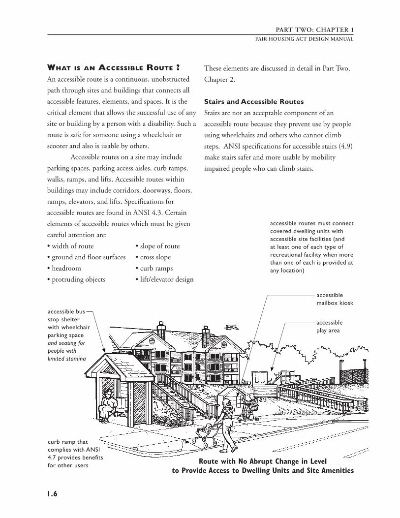
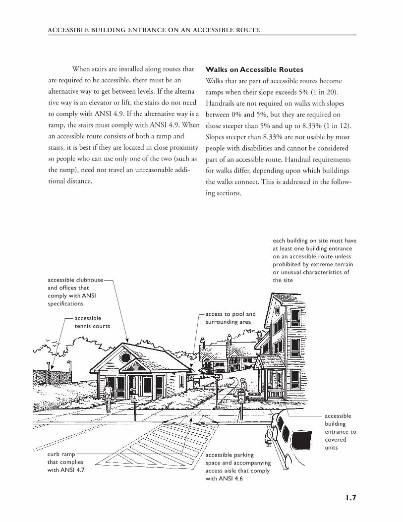
WHAT IS AN ACCESSIBLE ROUTE ? An accessible route is a continuous, unobstructed
path through sites and buildings that connects all
accessible features, elements, and spaces. It is the
critical element that allows the successful use of any
site or building by a person with a disability. Such a
buildings may include corridors, doorways, floors,
ramps, elevators, and lifts. Specifications for
accessible routes are found in ANSI 4.3. Certain
elements of accessible routes which must be given
careful attention are:
• width of route • slope of route
• ground and floor surfaces • cross slope
• headroom • curb ramps
• protruding objects • lift/elevator design
stop shelter
parking space
people with
FAIR HOUSING ACT DESIGN MANUAL
These elements are discussed in detail in Part Two,
Chapter 2.
Stairs and Accessible Routes
Stairs are not an acceptable component of an
accessible route because they prevent use by people
using wheelchairs and others who cannot climb
steps. ANSI specifications for accessible stairs (4.9)
make stairs safer and more usable by mobility
impaired people who can climb stairs.
accessible routes must connect covered dwelling units with accessible site facilities (and at least one of each type of recreational facility when more than one of each is provided at any location)
accessible bus
with wheelchair
limited stamina
accessible
curb ramp that
accessible
and seating for
play area
Route with No Abrupt Change in Level
complies with ANSI 4.7 provides benefits
mailbox kiosk
for other users to Provide Access to Dwelling Units and Site Amenities
1.6
ACCESSIBLE BUILDING ENTRANCE ON AN ACCESSIBLE ROUTE
When stairs are installed along routes that
are required to be accessible, there must be an
alternative way to get between levels. If the alterna
tive way is an elevator or lift, the stairs do not need
to comply with ANSI 4.9. If the alternative way is a
ramp, the stairs must comply with ANSI 4.9. When
an accessible route consists of both a ramp and
stairs, it is best if they are located in close proximity
so people who can use only one of the two (such as
the ramp), need not travel an unreasonable addi
tional distance.
accessible clubhouse and offices that comply with ANSI specifications
accessibletennis courts
curb ramp that complies with ANSI 4.7
Walks on Accessible Routes
Walks that are part of accessible routes become
ramps when their slope exceeds 5% (1 in 20).
Handrails are not required on walks with slopes
between 0% and 5%, but they are required on
those steeper than 5% and up to 8.33% (1 in 12).
Slopes steeper than 8.33% are not usable by most
people with disabilities and cannot be considered
part of an accessible route. Handrail requirements
for walks differ, depending upon which buildings
the walks connect. This is addressed in the follow
ing sections.
each building on site must have at least one building entrance on an accessible route unless prohibited by extreme terrain or unusual characteristics of the site
access to pool and surrounding area
accessible building entrance to covered units
accessible parking space and accompanying access aisle that comply with ANSI 4.6
1.7
PART TWO: CHAPTER 1
WHERE ARE ACCESSIBLE ROUTES
REQUIRED ON SITES?
Accessible Route from Site Arrival Points
to Accessible Building Entrances
The Guidelines require that an accessible route be
zones, and public streets or sidewalks to accessible
building entrances unless it is impractical to do so
as determined by application of the site tests
specified in Requirement 1(site impracticality due
to terrain or unusual site characteristics, see page
1.38). Because these walkways are required to be
accessible, handrails, as per ANSI, must be pro
vided when the slope of the walk is between 5%
(1 in 20) and 8.33% (1 in 12).
Accessible Routes and Walks Between
Accessible Buildings and Site Facilities
The Guidelines require accessible routes to connect
buildings containing covered dwelling units (those
with one or more elevators and ground floors of
other buildings, except two-story townhouses) and
accessible facilities, elements, and spaces on the
same site. The Guidelines do not require accessible
routes, walks, or paths between buildings contain
ing only covered dwelling units unless the route is
also part of a required accessible route. For ex
ample, if a building also contains a facility such as a
laundry that is shared by two buildings, then an
accessible route must be provided between the two
buildings.
If no portion of the finished grade of a
route between two buildings that contain only
dwelling units exceeds 8.33% (1 in 12), it is
FAIR HOUSING ACT DESIGN MANUAL
recommended that the route be made accessible.
Such voluntary accessible walks must meet the
same specifications as an accessible route except
that handrails, commonly required on accessible
routes when their slope exceeds 5% (1 in 20), are
not required.
Accessible Site Facilities
on Accessible Routes
The Guidelines require accessible and usable public
and common use areas. All facilities, elements, and
spaces that are part of public and common use
areas must meet ANSI 4.1 through 4.30 and must
be on an accessible route from covered dwelling
units. Such facilities might include outside mail
boxes, site furnishings, outside storage areas, refuse
disposal areas, playing fields, amphitheaters, picnic
sites, swimming pools and sun decks, tennis courts,
clubhouses, playgrounds, gazebos, parking areas,
sidewalks, and all or part of nature trails and
jogging paths.
Where multiple recreational facilities of the
same type are provided at the same location on the
site (e.g., tennis courts), not all but a “sufficient”
number of the facilities must be accessible to
ensure an equitable opportunity for use by people
with disabilities. Whenever only one of a type of
recreational facility is provided at a particular
location on the site, it must be accessible and
connected by an accessible route to the covered
dwelling units. (See Chapter 2: “Accessible Public
and Common Use Spaces.”)
1.8
ACCESSIBLE BUILDING ENTRANCE ON AN ACCESSIBLE ROUTE
Use of Vehicles for
Access to Site Facilities
When the finished grade exceeds 1 in 12 or other
physical barriers (natural or man made) or legal
restrictions, all of which are outside the control of
the owner, prevent the installation of an accessible
pedestrian route between covered dwellings and
some public or common use site facilities; the
Guidelines allow for automobiles to be used for
access if certain conditions are met. When such a
vehicular route is used as an alternative method to
achieve accessibility:
1. the required parking at covered dwelling units
must be provided, and
2. an appropriate number of additional accessible
parking spaces on an accessible route must be
provided at each facility that is otherwise unreach
able by means of an accessible pedestrian route.
For a complete discussion of parking requirements,
see Chapter 2: “Accessible and Usable Public and
Common Use Areas.”
Careful planning and strategic location of
accessible parking spaces and curb ramps around
dwelling units and amenities will help give conti
nuity between vehicular and pedestrian accessible
routes. Accessible parking spaces and curb ramps
are recommended at all on-site amenities to give
residents choices in how to reach them, even those
served by accessible pedestrian routes. This is
especially important where accessible routes are
very long and where parts or all of the route have
maximum allowable slopes of 1 in 12 (1:12), which
are difficult or impossible for many people to use.
accessible parking spaces and other access
amenities
inaccessible pedestrian
to on-site amenities
(typical on-site
features are required at site
routes from dwelling unit
tennis court
accessible parking spaces at dwelling unit
In Some Circumstances,Site Access by Vehicle May Be Acceptable
amenity)
1.9
PART TWO: CHAPTER 1
ACCESSIBLE ENTRANCES
All buildings containing covered dwelling units and
separate buildings containing public and common
use spaces, such as clubhouses, must have at least
one accessible building entrance on an accessible
route, unless it is impractical to do so as deter
mined by applying the site impracticality tests
provided in the Guidelines; see pages 1.38 through
1.58. Entrances into individual dwellings on an
interior accessible route are referred to in the
Guidelines as “entries.” These entries and the
entries to dwelling units having separate exterior
ground floor entrances will be discussed in
Chapter 3: “Usable Doors.” The Guidelines
establish three requirements for an accessible
building entrance.
Accessible Building Entrance
on an Accessible Route
The building entrance must be connected by an
accessible route to public transportation stops, to
accessible parking and passenger loading zones,
and to public streets or sidewalks.
FAIR HOUSING ACT DESIGN MANUAL
Primary Use
The accessible (common use) entrance must be one
which is typically used by residents and/or guests for
the purpose of entering the building. Service doors
or loading docks cannot serve as the only accessible
entrance to buildings, even if residents occasionally
use such a door for entering the building.
Building Entrance Design Features
The entrance door itself must be usable by people
with disabilities. Detailed specifications to achieve
this are given in ANSI 4.13. Accessible building
entrances are considered public and common use
spaces and, unlike unit entrances, must meet the
ANSI requirements on both sides of the door; see
the next page.
Main factors which must be addressed are:
• minimum clear width of open doorway 32 inches,
• low or no threshold,
• clear maneuvering space inside and
outside the door,
• force needed to open the door,
• accessible door hardware, and
• safe door closing speed.
accessible entrance accessible entrance
Accessible Primary Use Entrance
service entrance may not be the primary or only
1.10
ACCESSIBLE BUILDING ENTRANCE ON AN ACCESSIBLE ROUTE
good general weather
illumination protection high intensity lighting focused at
wide angle peep hole in door)
open door (ANSI 4.13.11)
door closer
period (ANSI 4.13.10)
between door and
easy-to-use door
4.13.9)
lighted doorbell buttons
clear width of
min. 32" (ANSI 4.13.5)
space next to latch side of door (ANSI 4.13.6)
adequate slope
build-up
(ANSI 4.13.8)
package shelf
view window (or
low force to
with safe sweep
clear, readable, high contrast signage
color contrast
frame
locks for people with low vision
lever or other
hardware (ANSI
open doorway
maneuvering
to prevent ice
low or no threshold
Call and mail boxes within reach of a seated person.
Design of Accessible Call boxes should be equipped Building Entranceswith both visual and audible signals so as to be usable by both Notes in italic type are recommendations only hearing and non-hearing people. and are not required by ANSI or the Guidelines.
All recommended features are helpful to people with and without disabilities.
1.11
PART TWO: CHAPTER 1FAIR HOUSING ACT DESIGN MANUAL
SITE PLANNING FOR ACCESSIBLE
ENTRANCES ON ACCESSIBLE ROUTES
The ease of establishing an accessible route at
building entrances can be radically affected by the
type of construction used and the placement and
positioning of the building on the site. These factors
should be considered along with others essential to
successful early planning and design of a housing
complex.
Careful Building Placement
Regardless of the type of construction, the way
in which a building is located on a site will affect
accessibility at entrances. If entrances exist at
locations where the floor level is close to the ground, parking often can be relocated to maximize use of
accessibility will be easier and less expensive to existing grades. In some cases, the best solution is
provide. Sometimes plans can be rotated or flipped to redesign the proposed floor plan to place en-
to bring entrances closer to grade. Entrances and trances at or as near grade as possible.
Plan to Place Entrance as Close Rotate, Flip, or Redesign Floor
to Grade as Possible
9 9
8 8
7 7
6 6
5 5
4 4
3 3
2 2
covered building
slope rises 3'-0''
covered building
between parking slope rises 1'-0'' between parking
and entrance and entrance
Current Position of Parking Lot Makes Accessible Reorientation of Parking Area toRoute Difficult or Impossible to Provide Achieve Accessible Route
1.12
ACCESSIBLE BUILDING ENTRANCE ON AN ACCESSIBLE ROUTE
Earthwork and Site Grading
It is often possible to create accessible routes to
entrances by means of earthwork and the grading
of sites. On sloping sites, fill can be added or the
land can be cut and graded to place the building
entrance at ground level.
line of existing grade with steeper slope
Bridges and Elevated Walks
Bridges or elevated walkways may be a good
solution to providing an accessible route to an
entrance on a sloping site, particularly where the
building is approached from an uphill location.
Combinations of techniques can be used on some
sites to provide accessible entrances on more than
one level. Bridges usually can be made level and
thus easy and safe for everyone.
line of existing grade
line of finished grade
waterproofing
Earth Cut Site Grading
compacted
waterproofing
earth fill with shallow slope
Earth Fill at Entrance
bridge
line of existing grade
Bridges to Uphill Locations on Sloping Sites
1.13
PART TWO: CHAPTER 1FAIR HOUSING ACT DESIGN MANUAL
line of finished grade
line of existing grade
compacted earth fill with shallow slope
waterproofing
Combination Earth Cut and Earth Berms and Bridges Accessible Bridge/Walk to Entrances On flat or irregular sites an accessible route to an
above grade entrance might be created by provid
ing a low retaining wall, an earth berm, and a
bridge. There are several advantages to this
method. The retaining wall is held several feet away
from the foundation forming a moat that allows
drainage and ventilation to occur at the foundation
the berm, if kept flush with the earth and less than
berm with
1:20 eliminates
handrails
bridgeand eliminates the need for additional waterproof
ing. The bridge from the retaining wall to the floor
landscaped garden entrance rather than an “access
Earth Berm and Bridge
paved walk at
need for ramps and required
moat for plants, drainage, and air circulation
retaining wall
of the building can be level. The sloping walk on
1:20 slope, will not require handrails, thus elimi
nating the awkward sloping appearance of access
ramps and their handrails. Plants on and around
the berm and in the moat create an attractive
ramp.”
1.14
ACCESSIBLE BUILDING ENTRANCE ON AN ACCESSIBLE ROUTE
In this site configuration a ramp provides the accessible route from several possible site arrival points to the building entrance. Often a ramp can ground floor units are be combined with stairs and a planter to create covered in this building attractive entrances that serve the needs of a without elevator(s) wide range of people.
accessible primary entrances to covered ground floor units
ramp and stairs that comply with ANSI 4.8 and 4.9 provide an accessible route to first floor covered units, slopes less than the max. 1:12 slope are recommended – for slopes at 1:20 or less, handrails are not required
Site Grading with Combined Ramp and Stairs
to Create Access to First Floor Units
curb ramp that complies with ANSI 4.7
access aisle and accessible parking spaces that comply with ANSI 4.6
site arrival points
Key Plan 4 Units on Each Floor
1.15
PART TWO: CHAPTER 1FAIR HOUSING ACT DESIGN MANUAL
In this site configuration the parking for the building is divided between two levels, with the accessible parking provided on the upper level. This solution creates the possibility of an accessible route, with little or no slope, to the building entrance and may reduce the required amount of earthwork necessary for a larger parking buildings without one or lot on the upper level that would serve the more elevators, only ground entire building. floor units are covered
access aisle and accessible parking
curb ramp that complies with ANSI 4.7
entrances to
floor units
ANSI 4.3
that complies with
first floor units
site arrival points
spaces that comply with ANSI 4.6
accessible primary
covered ground
walk that is part of an accessible route must comply with
Earthwork and Site Grading to Achieve Access to Ground Floor Units
accessible route,
ANSI 4.3, from upper level site arrival point to
Key Plan 4 Units on Each Floor
1.16
ACCESSIBLE BUILDING ENTRANCE ON AN ACCESSIBLE ROUTE
point to the accessible
floor at the far end of the building.
arrival point
side of the building.
l
of an accessible
ANSI 4.3
curb ramp that complies with ANSI 4.7
l units and up to
units
access aisle and accessible parking
the near end of the building
Accessible route from lower level site arrival
ground floor entrances to two covered units on the lower level ground
upper level site
Access by level bridge and walk provides an accessible route from site arrival points to entrance of two covered units on the second floor level on this
In this site configuration a combination of levewalkway and bridge is used to create an accessible route to the units on the second floor. On such sloping sites, bridges can provide convenient, safer, and direct access to the upper level.
this walk is part
route and must comply with
stairs down to two lower leve
two top floor
If the resulting design plan was such that the two units on the lower ground floor at
were on an accessible route, Bridge to Achieve Access that comply with those units would also be to Second Floor Units ANSI 4.6covered.
this building has four dwelling units on each floor with separate unit entrances and stairs at each end
Key Plan 4 Units on Each Floor
1.17
PART TWO: CHAPTER 1FAIR HOUSING ACT DESIGN MANUAL
In this site configuration an ordinary site feature, a bridge over a stream, has been integrated with a level walkway to create an accessible route to the ground floor units of the building.
access by level bridge and walk provide an accessible route from site arrival points to primary entrances to two ground floor covered units at the near end of the building
accessible route from site arrival point to accessible primary entrances to two ground floor units at the far end of the building
level bridge with surface flush with walk surfaces
walk that is part of an accessible
site route must comply arrival with ANSI 4.3 point
Bridge to Achieve Access to Ground Floor Units
access aisle and accessible parking spaces curb ramp that that comply complies with with ANSI 4.6 ANSI 4.7
Key Plan 4 Units on Each Floor
1.18
ACCESSIBLE BUILDING ENTRANCE ON AN ACCESSIBLE ROUTE
entrances on a central double-
stairs need not
single building with
all units in the
Guidelines
this building has four units on each floor, each with primary
comply with ANSI 4.9, recommended compliance for safe egress
elevator and bridges;
building are covered and must meet the
elevator
Building with Exterior Elevator (All Units are Covered)
accessible route from site entry points via the exterior elevator to the primary entrance of each dwelling unit
site arrival point
access aisle and accessible parking spaces that comply with ANSI 4.6
curb ramp that complies with ANSI 4.7
Key Plan loaded corridor
4 Units on Each Floor
1.19
PART TWO: CHAPTER 1FAIR HOUSING ACT DESIGN MANUAL
COVERED DWELLING UNITS AND
THEIR ACCESSIBLE ENTRANCES
In buildings containing multiple dwelling units,
common use exterior entrances and individual
exterior entrances to ground floor units are
required by the Guidelines to be accessible, unless
it is impractical to do so as determined by one of
the site impracticality tests discussed in the next
section on pages 1.38 through 1.58.
It is expected that all multifamily buildings
will have covered dwelling units. However, the
configuration of the building; the location of the
entrances; the determination of which is the
ground floor(s) (there can be more than one); the
placement, origin, and destination (range) of
elevators; and site impracticality will affect which
units in multifamily buildings are covered and
where or how accessible entrances are provided.
This section of the manual discusses coverage and
accessible exterior entrances in
1. buildings having one or more elevators,
in a building with one or more elevators that go to units above or below
2. buildings with separate ground floor entrances to
dwelling units, and
3. buildings with common entrances.
Entrances to covered dwelling units from
interior halls, corridors, or accessible common use
spaces are discussed in Chapter 3: “Usable Doors.”
Based on the legislative history of the Fair
Housing Act, it is expected that only extreme
conditions of a site may make it impractical to
provide an accessible route to entrances of some
covered dwelling units. The Guidelines allow, in
some instances, the number of covered units to be
reduced where such impracticality can be demon
strated. Requirement 1 of the Guidelines includes
two site impracticality tests that can be used to
determine if an accessible route at a required
entrance is impractical due to extreme terrain or site
conditions. The tests are referenced in this section
and their applications are described in detail on
pages 1.38 to 1.58 of this chapter.
= covered units
ground floor units, all dwelling units in the building must be on an elevator accessible route and all units must comply with
buildings with one orRequirements 3-7 more elevators, regardless of site conditions, must have at least one accessible entrance on
ground floor units an accessible route
In Buildings with One or More Elevators: (Elevator Buildings) All Units are Covered
1.20
ACCESSIBLE BUILDING ENTRANCE ON AN ACCESSIBLE ROUTE
BUILDINGS WITH ELEVATORS
All dwelling units are covered in buildings having
one or more elevators and one or more common
entrances. The Guidelines require that such
buildings with elevators (elevator buildings) have at
least one accessible entrance on an accessible route,
regardless of the terrain or unusual characteristics
of the site. In other words, site impracticality as
defined in the tests discussed on pages 1.38
through 1.58 is not allowed for “buildings having
one or more elevators.”
The rationale for disallowing site impracti
cality for such buildings includes the assumption
that a building having elevators is a mid- to
high-rise building and that all floors are accessible
via the elevators. In addition, it is expected that the
site work performed when building such elevator
buildings generally results in a finished grade that
would make an accessible route into and through
the building practical. For a building to meet the
Fair Housing Act definition of a “building having
one or more elevators” (elevator building), it must
have at least one elevator that travels from an
accessible entrance
required
elevators
all units are covered
Termination of Elevator as Shown in this Building is NOT Acceptable
when an elevator provides access to dwelling units other than dwelling units on a ground floor, it becomes a “building with one or more elevators” and the elevator must go to all floors and all dwelling units are covered
= covered units
that is above or below a “ground floor.” If such an
elevator is planned, it must go to all floors that
contain dwelling units. Thus, it is not acceptable to
provide elevator service to some floors or units and
not others.
In the building shown in the upper right
column on this page, the elevator only goes to the
first and second floors containing dwelling units.
This is unacceptable because the elevator is going
to a floor other than a ground floor (floor two),
therefore, floors three and four also must have
access via the elevator.
accessible entrance elevators
required
entrance level to a floor containing dwelling units
all units are covered
Elevators Must Provide Access to All Dwelling Units in Elevator Buildings
1.21
PART TWO: CHAPTER 1FAIR HOUSING ACT DESIGN MANUAL
In the example to the right, if the elevator elevator must have stops
stops at floors other than just one, the building is at all floors containing single-story units and at
classified as a building with one or more elevators the primary entry floor of = covered units two-story dwelling units (an elevator building), and the elevator must have a
stop at the second and fourth floors. Floor three is single-story
not required to have a stop since it contains only dwelling unit
second floors of two-story dwelling units. Note:
most building codes require buildings over three second story of two-story
stories to have elevators. All such buildings are dwellings
covered by the Guidelines. first story of two-story dwellings
single-story dwelling units
4
3
2
1
Elevators Must Provide Access to Primary Entry Floors of Two-Story
Dwellings in Elevator Buildings
both buildings are covered – all units must be accessible
elevator
connecting walkways
If an elevator in or at one building is
connected to other buildings via overhead walks or
bridges, the connectors must be accessible and all
the connected buildings are covered.
A Central Elevator Serving a Building with Two Wings
1.22
ACCESSIBLE BUILDING ENTRANCE ON AN ACCESSIBLE ROUTE
FREE-STANDING ELEVATORS
FOR SITE ACCESS DO NOT CREATE
ELEVATOR BUILDINGS
serve as part of an accessible route from one site
building’s status as an elevator or nonelevator
building.
elevator
drop-off zone and
BUILDINGS NOT HAVING ELEVATORS
In buildings not having elevators, only ground
floor dwelling units are covered and each dwelling
unit must be on an accessible route and meet
Requirements 3-7.
Buildings not having elevators must have at
least one accessible entrance on an accessible route,
unless prohibited by extreme terrain or unusual site
characteristics. See site impracticality section, page
1.38. Note, in buildings either with or without
elevators, more than one accessible entrance may
be required when:
1. there is more than one ground floor,
2. there is a split-level ground floor, or
3. units are clustered on the ground floor and each
cluster has a separate entrance.
These situations are covered on the next several
pages.
l
common and individual unit
l
free-standing
parking leve
upper terrace
entrance leve
Free-standing elevators not connected to buildings
level to another and do not have any effect on the
Free-Standing Elevators for Site Access Do Not Create Elevator Buildings
= covered units
floor units ground
In Buildings Not Having Elevators(Nonelevator Buildings)
Only Ground Floor Units Are Covered
1.23
PART TWO: CHAPTER 1
In some circumstances the “ground floor”
units that are covered may not actually be at grade
level. For example, when common use spaces such
as parking, meeting rooms, shops, etc. occupy the
floor at grade, the first floor containing dwelling
units above or below that level will be the desig
nated “ground floor” for purposes of the Guide
lines. All dwelling units on such levels must meet
Requirements 3-7 and be on an accessible route.
It is important to note that some buildings
may contain an elevator and not be considered a
“building having one or more elevators” for pur
poses of the Guidelines. For example, when an
elevator travels from a garage or other entry level
not containing dwelling units only to a “ground
floor” containing dwelling units, these “ground
floor” units are covered; however, the building is
not a “building having one or more elevators”
(elevator building) and the elevator is not required
to travel to all floors.
FAIR HOUSING ACT DESIGN MANUAL
other floor units
common use space
accessible entrance not covered
elevator
ground floor units covered
required
Elevator to First Floor of Dwelling Units Above Grade or Entrance Level Does Not Make a
Building with One or More Elevators (a Covered Elevator Building)
= covered units
If a building elevator is provided only as a means of creating an accessible route from parking to dwelling units on a ground floor, the building is not considered an elevator building. In this case, the dwelling units on the “ground floor,” plus one of each type of public and common use area, must comply with the Guidelines.
floor an accessible
ground elevator provides
route from parking to ground floor covered units
Elevators for Access to Ground Floor Units Do Not Make an Elevator Building
1.24
ACCESSIBLE BUILDING ENTRANCE ON AN ACCESSIBLE ROUTE
BUILDINGS HAVING
CONNECTED ELEVATOR AND
NON-ELEVATOR WINGS
Buildings having multiple wings of different
configurations may have to provide more than one
entrance and possibly more than one elevator. If
any wing has an elevator, all of the units in the
building are covered and must be on an accessible
route.
In the example below, a single building has
two wings, one of which has an elevator. A lobby or
similar public and common use space connects the
wings and serves both wings. All the units in the
building are covered, therefore, the building either
must have an additional elevator serving the two-
story wing, or an alternative means of access to the
common use entrance and lobby provide interior accessible route between bottom floors of both wings
Buildings with Multiple Wings
dwelling units on the second floor of the two-story
wing. In addition, since the two wings share the
common use entrance, lobby, and related ameni
ties, such as mailboxes, reception desk, etc., there
must be an interior accessible route between the
lobby and the two-story wing. In this example, an
accessible route has been created from the second
floor of the five-story wing to the second floor of
the two-story wing by means of a covered walkway,
thereby providing the necessary access.
= covered units
elevatorsalternate solution:
entrance and
floors this wing
all units are covered
covered walkway from second story of five-story wing to second story of low-rise wing
provide accessible
route to both
all units are covered
lobby
1.25
PART TWO: CHAPTER 1
BUILDINGS WITH SEPARATE
EXTERIOR UNIT ENTRANCES
BUILDINGS WITH SEPARATE EXTERIOR
GROUND FLOOR UNIT ENTRANCES
Where a building has ground floor units, each with
its own exterior entrance, the Guidelines provide
that each of these ground-floor units shall:
1. have an accessible entrance,
2. be on an accessible route, and
3. meet all other design requirements of the
Guidelines.
The only exception applies to ground floor units
where terrain or unusual characteristics of the site
make an accessible entrance on an accessible
route impractical.
= covered units
impractical ground floor entrance serving unit #5
5
stairs to noncovered unit #3
FAIR HOUSING ACT DESIGN MANUAL
The example below is a single non-elevator
building on a site and has multiple entrances.
Regardless of which site impracticality test is used,
a minimum of 20% of the ground floor units must
be accessible, and possibly more, based on the
results of the test. The individual building test was
used, and resulted in site impracticality at Unit #5.
The site was not impractical for Units #1 and #2,
and therefore, those units must be made accessible.
Two out of three units = 66%, so the minimum of
20% has been satisfied, and no additional ground
floor units must be made accessible. See site
impracticality on page 1.38.
stairs serving noncovered units #4
6 and #6
1 6
4 4
3 1
3
2
accessible entrances to covered dwelling units #1
Ground Floor Units with and #2 Separate Entrances Are Covered
1.26
ACCESSIBLE BUILDING ENTRANCE ON AN ACCESSIBLE ROUTE
BUILDINGS WITH SEPARATE
GROUND FLOOR UNIT ENTRANCES ON
TWO OR MORE GROUND FLOORS
Where a building has ground floor units with their
own individual entrances on two or more ground
floors, the Guidelines provide that each of these
entrances shall be an accessible entrance on an
accessible route. The only exception to this applies
to ground floor units where terrain or unusual
characteristics of the site make an accessible entrance
impractical, see site impracticality tests, page 1.38.
= covered units
stairs at this
Since entrances were planned on both ground floors and all ground floor units are covered, each must have an accessible entrance on an accessible route and meet the other design requirements of the Guidelines.
building serve ing serve stairs at this end of
noncovered units
end of build
noncovered #3, #5, and #9unit #10
10
8
9
7upper gr
ound
floor level
5
r groundaccessible entrance
to covered units #7 and #8
3 eeflo
or lelow16
4accessible entrance to covered unit #4
stair and entrance to noncovered
2
accessible entrances to covered
Ground Floor Units dwelling units on Two Ground Floors Are Covered #1 and #2
unit #6
1.27
v l
PART TWO: CHAPTER 1
BUILDINGS WITH SEPARATE UNIT
ENTRANCES HAVING SPLIT-LEVEL
APPROACHES
Apartments with split-level approaches to their
entrances typically cannot provide an accessible
route from parking or other pedestrian arrival
points to either lower or upper level primary
entrances. Redesign is necessary to ensure an
accessible building entrance on an accessible route
to ground floor units. Note, however, that simply
=covered units
secondary (patio) door
NOT Acceptable – Lacks an Accessible Route to a Primary Entrance Door
l
parking
no entrance covered ground floor unit
primary entrance
pedestrian route to upper leveunits from
secondary or
primary entrance
secondary entrance (balcony)
Solution One: Reorient Ground Floor Plan to Reverse Entrances
parking and accessible route
Solution Two is for a building having single-story units on each floor. Note, however, that if multistory units are stacked over the single-story units, then the building is still covered, and access to the single-story units secondary entrances would be required, as shown in Solution One.
Solution Two: Regrade and Add Bridge from Parking to Second Story Entrance
FAIR HOUSING ACT DESIGN MANUAL
adding an accessible route to the secondary, rear
entry is not acceptable as that results in “back door”
access. See the first illustration and Solution One.
In Solution Two, regrading and the addi
tion of a bridge provides access to the upper level,
making that level the ground floor. Because no
primary entrance was planned at the rear of the
lower level units, and since there is no requirement
to have more than one ground floor, an accessible
route is not required to those units.
parking“back door” will not suffice
doors
pedestrian route to units from
covered ground floor unit
stacked single-story units
an accessible route to this
primary entry
8.33% and no abrupt change
l
two-story townhouse
elevated walkway with a slope no greater than
in leve
single-story covered unit If the units are one story, either level could be
designated as the ground floor. If two-story townhouses are stacked over one-story units on grade, the building is still covered. Access must be provided to the lower units.
primary entrance
1.28
ACCESSIBLE BUILDING ENTRANCE ON AN ACCESSIBLE ROUTE
BUILDINGS WITH SEPARATE GROUND
FLOOR UNIT ENTRANCES OVER
PRIVATE GARAGES (CARRIAGE UNITS)
Carriage House Units
Carriage houses in which the garage footprint
is used as the footprint for the remaining floor
Carriage Units in Buildings Having One or
and is covered
an attached
3 single-story single-story
dwelling units dwelling unit at grade level
or floors of the units are not required to meet over private establishes aone- or two-car
the design and construction requirements. (See garages ground floor
December 16, 1991 memorandum from Frank for this building
Keating at back of Appendix C.)
If buildings containing carriage units have
one or more units at grade level with an entrance on
an accessible route, the grade level unit establishes
a ground floor for the building and is covered. More Grade Level Units Are Not Covered There is no requirement for there to be more than
one ground floor nor for other units in the building covered units =
on the second or elevated floor to be accessible.
if visitor or public parking
accessible spaces with accessible entrances
is provided, an accessible route should connect
4 or more carriage units with separate ground floor accessible entrances
an interior accessible route to garage spaces is not required
an exterior vehicular or accessible pedestrian route to garages is required
Carriage Units Having an Accessible Route to an Entry Are Covered
1.29
PART TWO: CHAPTER 1FAIR HOUSING ACT DESIGN MANUAL
Guidelines, it subjects people with
to parking and exposes them in an
with assigned parking
an accessible entrance onThis building accessed
This elevator serves several buildings on the site. Although this configuration meets the requirements of the
disabilities to using a more circuitous route from the dwelling unit entrances
unequal way to inclement weather
single-story walk-up units on second floor above common garage space are not covered
single-story dwelling units over a common garage
spaces are covered ground floor units and must have
an accessible route
elevator
conditions.
by another, similar elevator at opposite end of the site.
accessible routes to ground floor unit entrances on upper grade level
drop-off zone common parking garage at grade level with assigned parking spaces and one interior set of stairs at
accessible route from a junction of two wings public street or sidewalk or other pedestrian Single-Story Ground Floor Dwelling
accessible route from arrival point to accessible Units with Separate Entrances entrances to covered units Over Common Use Parking Garages
elevator to create an accessible route from parking to ground floor does not make these elevator buildings
parking to accessible common or individual ground level entrances to covered units
1.30
ACCESSIBLE BUILDING ENTRANCE ON AN ACCESSIBLE ROUTE
BUILDINGS WITH COMMON ENTRANCES
Buildings with Ground Floors an accessible route to
Over Shops or Garages dwelling unit entrances must be provided
parking, shops, or other common use spaces
third floor single-story units are not covered
covered single-story units
Where the first floor containing dwelling units in a
building is above grade, all units on that floor are
covered and must be served by a building entrance
on an accessible route. This floor will be considered
a ground floor, thus making dwelling units over
retail stores, garages, or other common use spaces
grade level is used entirely for
covered units.
ground floor for purposes of the Guidelines
three-story building of single-story dwelling units on a double-loaded open-air corridor
parking at grade level are covered
or bridge is required to provide accessible route to covered units
Note: if the elevator is also taken to the next level, the building becomes a building with one or more elevators and all floors and units must comply.
If one or more single-story dwelling units with an accessible entrance on an accessible route are located at grade level in buildings otherwise having public or common use parking or shops at grade level, a new grade level ground floor is established and only the grade level units are covered.
= covered units
stairs
elevator
common use parking
elevator, ramp, lift, elevated walkway,
single-story units above common use
Walk-Up Dwelling Units Over Garages, Shops, and Other Public or Common Use Spaces Are Covered
shops or common use parking
covered single-story unit
One or More Grade Level Accessible Units Establishes a Ground Floor and Eliminates Need for
Accessible Routes to Units Over Garages or Shops
1.31
PART TWO: CHAPTER 1
BUILDINGS WITH ONE OR MORE
COMMON ENTRANCES
When a building has one or more common en
trances, the Guidelines provide that at least one of
these entrances shall be accessible and shall be on
an accessible route to all dwelling units in build
ings with one or more elevators, and to all ground
floor units in nonelevator buildings. Examples of
how this applies to specific buildings and sites
follow. The only situation where an accessible
entrance is not required is when there is a single
building with a single entrance on a site with no
elevator, and the terrain or unusual characteristics
elevator
FAIR HOUSING ACT DESIGN MANUAL
This is a single building on a site. It has two common entrances and an elevator serving multiple floors. Because it is a building with one or more elevators (an elevator building), all units in the building are covered, and at least one common entrance must be accessible and on an accessible route from a public street or sidewalk or other pedestrian arrival point, regardless of the terrain or unusual characteristics of the site; site impracticality tests do not apply for elevator buildings.
page 1.38.
be one which is
purpose of entering the building, and
entrance is some
although acceptable under the
all floors
of the site make the provision of an accessible route
to the entrance impractical. See site impracticality,
required accessible entrance must always
typically used by residents for the
cannot be a service entrance, even if that
times used by residents
inaccessible secondary entrance,
Guidelines, may have to be accessible to meet local, state, and other emergency egress requirements
accessible route to all dwelling units on
Buildings with Common Entrances
1.32
ACCESSIBLE BUILDING ENTRANCE ON AN ACCESSIBLE ROUTE
BUILDINGS WITH COMMON
ENTRANCES AND A SINGLE
GROUND FLOOR
When a building has a single ground floor and
more than one common entrance, at least one
entrance must be accessible. This accessible
entrance should be the primary entrance and must
provide an interior accessible route to all ground
floor units in the building. If an interior accessible = covered units
route does not connect the primary entrance to all
ground floor units, additional entrances on
accessible routes are necessary to reach the addi
tional ground floor units.
entrances must be
accessible entrance
accessible entrance onnot all ground floor
accessible, but more than one may be necessary under some circumstances
nonelevator building with one ground floor, must have at least one
all ground floor units are covered and must be served by an
an accessible route
Common Entrances in Buildings with a Single Ground Floor
1.33
PART TWO: CHAPTER 1FAIR HOUSING ACT DESIGN MANUAL
BUILDINGS WITH COMMON
ENTRANCES AND CLUSTERED
DWELLING UNITS
Where dwelling units are clustered in a building,
each cluster which has its own entrance or entrances
shall have at least one accessible entrance providing
access to all ground floor units in the cluster.
even though this cluster contains only three units, all are covered units because the cluster is part of the overall building
Guidelines, may have to be accessible to meet local, state, or other emergency egress requirements Common Entrances at least one of the
This is a single building with
common use entrances
an accessible entrance on an
accessible
entrance
be accessible
although acceptable under the
no elevator and with multiple
serving clustered dwelling units. Each cluster must have
accessible route.
primary
this entrance must
inaccessible secondary entrances,
at Clustered Dwelling Units three entrances serving this cluster must be accessible and on an accessible route
1.34
ACCESSIBLE BUILDING ENTRANCE ON AN ACCESSIBLE ROUTE
BUILDINGS WITH SPLIT-LEVEL
GROUND FLOORS
Split-level floors of less than a full story in height
are not separate floor levels and are considered to
be one ground floor. Covered ground floor units
on each level must have entry doors on an acces
sible route connecting to at least one accessible
common use building entrance and at least one of
each type of common use facility or feature, such as
mail rooms, laundries, vending areas, etc. Since
steps and stairs cannot be part of an accessible
route, changes in level on covered floors must be
accomplished by means of ramps, lifts, or elevators.
If an accessible route, in lieu of or in
addition to steps or stairs, is provided between
levels, the route must not be remote, hidden,
circuitous, or require people with disabilities to
travel excessively long distances to arrive at the
same point as others. Finally, the accessible route
between levels must be readily available to all
residents and visitors and not be locked or require
keys, attendants, or special services or permits
for use.
If an accessible route is not provided
between covered floor levels, each level must have
its own accessible common use entrance on an
accessible route; any common use facilities or
features provided on one level must also be avail
able on an accessible route on each other level.
Apt D
Apt C
Apt BApt
A
multiple dwelling steps must be replaced units on all levels or accompanied by an
accessible route – OR –
additional common use additional entrance accessible entrances and on each level may other facilities must be be necessary provided on each level
Split-Level Ground Floor Regarded as Single Ground Floor
1.35
PART TWO: CHAPTER 1FAIR HOUSING ACT DESIGN MANUAL
BUILDINGS WITH COMMON
ENTRANCES AND MORE THAN
ONE GROUND FLOOR
In building designs that are planned to have more
than one ground floor, an entrance on each ground
floor is required to be accessible unless site condi
tions make it impractical to provide an accessible
route to each entrance. See page 1.38 for site
impracticality. In this illustrated example, the
planned location of parking and sidewalks (that
would serve as the pedestrian and vehicular arrival
points) is close to the planned entrances, with only
minor changes in level between the arrival points
and the floor level of the building at the planned
entrances, therefore, it is practical to make the
planned entrances accessible. Because the common
floors
accessible and on an accessible
practical to do so
middle level units are covered
lower level units are covered
two ground
all entrances are
route because it is
entrances are accessible via an accessible route, all
the dwelling units served by each entrance are
covered dwelling units and must meet the require
ments of the Guidelines.
Common Entrances at Buildings with More Than One Ground Floor
1.36
ACCESSIBLE BUILDING ENTRANCE ON AN ACCESSIBLE ROUTE
BUILDING FLOORS HAVING
COMMON ENTRANCES SERVED BY
ELEVATED WALKWAYS
When a developer plans an elevated walkway from
a pedestrian or vehicular arrival point to the
building entrance and the walkway has a slope of
10% or less, that floor shall be considered a ground
floor. The dwelling units on that floor are covered
and the site is not considered impractical. Since the
walkway meets the 10% slope criterion, it is
practical to provide an accessible route to the
entrance, and the slope of the walkway must be
reduced to 8.33% maximum. accessible route to both of the first floor
one is planned and its
inaccessible common entrance
second floor common entrance causes this floor to be
common entrances is impractical
Elevated walkways are not required; however, if
Elevated Walkways to Accessible Entrances
accessible route to accessible
considered a ground floor
slope is no greater than 10%, then the slope must be reduced to 8.33% maximum and the dwelling units on that floor shall be accessible.
1.37
PART TWO: CHAPTER 1FAIR HOUSING ACT DESIGN MANUAL
SITE IMPRACTICALITY
INTRODUCTION
HUD’s regulations implementing the Fair Housing
Act state:
Covered multifamily dwellings for first occupancy after March 13, 1991 shall be designed and constructed to have at least one building entrance on an accessible route unless it is impractical to do because of the terrain or unusual characteristics of the site. [24 CFR 100.205(a)].
The Fair Housing Act itself does not contain an
impracticality exception; however, the preamble to
HUD’s regulations explains as follows: “Congress
did not intend to impose an absolute standard that
all covered multifamily dwelling units be made
accessible without regard to the impracticality of
doing so. Even though the statute itself does not
contain an impracticality standard the legislative
history makes it clear that Congress ‘was sensitive
to the possibility that certain natural terrain may
pose unique building problems’.” Thus, the
regulations and the Guidelines recognize that
certain site conditions may make it impractical to
make all ground floor units accessible in buildings
that do not have an elevator due to the difficulty of
providing an accessible route to the building
entrance or to individual dwelling unit entrances.
The Guidelines provide tests for determining site
impracticality, which are discussed beginning on
page 1.40.
Elevators from garages or grade levels to ground floors need not serve other floors and only the ground floor dwelling units must meet the design requirements of the Guidelines.
Buildings With Elevators, Including Those Having Elevators Only for Access
to Covered Ground Floor Units, Cannot Claim Site Impracticality
accessible entrance is required
Elevator From Garage to Covered Ground Floor Units
units
accessible
required common use
spaces
entrance is
ground floor
Elevator From Garage Levels to Ground Floor Units Above Common Use Grade Level Floor
ground
common use spaces
accessible entrance
floor units
required
Elevator From Grade Level Common Use Spaces to Covered Ground Floor Units Above
1.38
ACCESSIBLE BUILDING ENTRANCE ON AN ACCESSIBLE ROUTE
If an elevator provides access to any floors other than a ground floor, then it must go to all floors in the building and all units in the building must meet the design requirements of the Guidelines.
accessible entrance
to floors other than
required
elevator from garage
ground floor units
elevator must go to all floors
Buildings with One or More Elevators Cannot Claim Site Impracticality
point
These building types for which site impracticality is
covered dwelling units
arrival
not permitted are illustrated on this page and 1.38.
Site impracticality is not allowed where the entrance to the building is provided by an elevated walkway between the building entrance and an arrival point with a planned slope no greater than 10%. By meeting the 10% slope criterion, it is considered practical to
BUILDING TYPES WHERE SITE
IMPRACTICALITY IS NOT ALLOWED
The Guidelines address the regulatory provision for
site impracticality discussed above in Requirement
1, Accessible Building Entrance on an Accessible
Route. The Guidelines do not allow site imprac
ticality for certain buildings. These buildings are:
1. Buildings with one or more elevators – These
buildings are covered and must have at least one
entrance on an accessible route regardless of
terrain or other characteristics of the site.
2. Buildings where an elevator is provided solely as
a means of access to units on a ground floor –
These buildings are covered and all ground floor
units must be accessible. However, this type of
building is not treated as an elevator building
where all of the units in the building are cov
ered. For a full explanation of buildings with
elevators, see pages 1.20 through 1.25.
3. Buildings that have an elevated walkway – Site
impracticality is not allowed for buildings where
an elevated walkway is planned between a
building entrance and a vehicular or pedestrian
arrival point and the planned walkway has a
slope no greater than 10%. The 10% criterion
only determines whether making the entrance is
practical. Once this criterion is met, the slope
would have to be reduced to a maximum of
8.33 %.
Buildings Served by a Planned Elevated provide an accessible route, and the slope must be Walkway Cannot Claim Site Impracticality reduced to 8.33% maximum.
1.39
PART TWO: CHAPTER 1
SITE IMPRACTICALITY TESTS
FOR SITES WITH DIFFICULT TERRAIN
The Guidelines provide two tests to determine
site impracticality based upon difficult terrain
conditions, the Individual Building Test and the
Site Analysis Test.
Since buildings with one or more elevators
and those served by a planned elevated walkway
cannot claim site impracticality, the site impracti
cality tests apply only to other types of buildings
on sites having extreme terrain or unusual charac
teristics. The tests will help determine the actual
number of units that must meet the Guidelines on
such sites.
The tests differ and their application will
be affected by the number of buildings on the site,
the number of planned entrances, the slope of the
land, and the distance between key points on the
planned site. Unusual site characteristics, including
such conditions as federally designated flood plains
or coastal high hazard areas where it is required to
raise the floor level of buildings above a base flood
elevation, also have an impact on the number of
covered dwelling units. Each of the tests follow the
Guidelines and conclude with a minimum required
number of accessible units.
The Individual Building Test accepts as
inaccessible, because of site impracticality due to
terrain, all ground floor units in which the eleva
tion difference between the undisturbed site grade
and the proposed finished site grade from arrival
points and the planned building entrance is over
10% when measured in a straight line. If either the
undisturbed slope or the proposed finished slope,
measured in a straight line, is 10% or less, then site
impracticality due to terrain does not exist and the
FAIR HOUSING ACT DESIGN MANUAL
developer must provide an accessible route to the
particular entrance being measured.
The Site Analysis Test measures the total
buildable area of undisturbed or natural grade
having an existing slope before grading less than
10% (Step A). The area of less than 10% slope is
expressed as a percentage of the total site area less
any restricted use areas such as wetlands or flood
plains. The percentage establishes the minimum
percentage of ground floor units to be made acces
sible (Step B) subject to the additional requirement
of Step C. Step C requires that, in addition to the
percentage established in Step B, all ground floor
units in a building or ground floor units served by
a particular entrance shall be made accessible if the
entrance to the units is on an accessible route,
defined as a walkway with a slope between the
planned entrance and a pedestrian or vehicular
arrival point that is no greater than 8.33%.
Which Tests Apply to Which Sites
The tests relate to different buildings and site
conditions. It is important to remember before
discussing the test applications that they are not
applicable to buildings having one or more elevators
(elevator buildings) because they already are covered
and all units in them must meet the requirements
of the Guidelines, and they must have at least one
entrance on an accessible route regardless of terrain
or other characteristics of the site. None of the
buildings described in the following explanation of
test applications are elevator buildings; nor are they
served by an elevated walkway between a building
entrance and an arrival point.
1.40
ACCESSIBLE BUILDING ENTRANCE ON AN ACCESSIBLE ROUTE
Sites Where Only the
Individual Building Test May be Used
For sites with difficult terrain which have a single
building with only one common entrance on the
site, the individual building test must be used. If
the results of this test determine that it is impracti
cal to make that entrance accessible, then the
building is not required to be accessible and none
of the ground floor units are covered. This is the
only circumstance under which an entire site may
not be covered.
Sites Where Either Test May be Used
Either test may be used for building sites having
multiple buildings or a single building with more
than one common entrance. When the Individual
Building Test is applied to such sites it must be
calculated for each building and each building
entrance separately.
Single Building on a Site with One Common Entrance
The 20% Rule
For those sites where either the Individual Build
ing Test or the Site Analysis Test may be used, the
Guidelines set a minimum percentage of ground
floor units, which serves as a starting point even
before the tests are applied. This minimum is 20%.
Thus, for those sites where either test may be used,
there never will be a situation where less than 20%
of the units are required to comply with the
Guidelines; in most cases the tests will result in a
much larger percentage of units required to be
accessible. Keep in mind that this 20% minimum
cannot be used as a maximum. The results of the
test, depending on which test is used, will
determine the maximum number of units required
to be accessible.
Note: The following examples apply only to buildings that do not have one or more elevators (elevator buildings). Buildings having one or more elevators must be accessible regardless of site conditions.
• one building • 4 or more units • 1 entrance
• must use the Individual Building Test
A site with a single building with one common entrance may not be required to be accessible if the site is impractical and application of the Individual Building Test determines impracticality at this entrance.
Example of Potentially Impractical Site Based on Terrain and Application of Individual Building Test
1.41
PART TWO: CHAPTER 1FAIR HOUSING ACT DESIGN MANUAL
Single Building with Multiple Entrances on a Site
Note: The following examples apply only to buildings that do not have one or more elevators (elevator buildings). Buildings having one or more elevators must be accessible regardless of site conditions.
• single building on a site• 4 or more units • 2 or more entrances • may use either the Individual
Building Test or the Site Analysis Test
A minimum 20% of ground floor units must comply with the requirements of the Guidelines, plus an additional number determined by application of one of the tests. In addition, if any entrance is made accessible to meet either the 20% minimum or the percentage resulting from the test: all units served by that entrance must comply.
• multiple buildings an a site• 4 or more units in each
building • 1 or more entrances
• may use either the Individual Building Test or the Site Analysis Test
A minimum 20% of ground floor units must comply with the requirements of the Guidelines, plus an additional number determined by application of one of the tests. In addition, if any entrance is made accessible to meet either the 20% minimum or the percentage resulting from the test:
Multiple Buildings on a Site all units served by that entrance must comply.
Examples of Potentially Impractical Sites Based on Terrain and Application of Site Impracticality Tests
1.42
ACCESSIBLE BUILDING ENTRANCE ON AN ACCESSIBLE ROUTE
INDIVIDUAL BUILDING TEST
The Individual Building Test must be used to
analyze a site with a single building with one
common entrance and also may be used for all
other sites. The Individual Building Test, unlike
the Site Analysis Test, does not have to be certified
by a professional licensed engineer, landscape
architect, or surveyor; but it should be calculated
on a topographic map with two-foot (or less)
contour intervals.
For it to be considered impractical to
provide an accessible route to any building or
individual dwelling unit entrance, the slope be
tween the pedestrian arrival points and the planned
entrances must meet both of the following two
conditions (quoted directly from the Guidelines):
STEP A. the slopes of the undisturbed site mea
sured between the planned entrance and all vehicu
lar or pedestrian arrival points within 50 feet of the
planned entrance exceed 10%; and
STEP B. the slopes of the planned finish grade
measured between the entrance and all vehicular or
pedestrian arrival points within 50 feet of the
planned entrance also exceed 10%.
planned location ground level of entrance at at center of existing grade doorway elevation
planned location of arrival point at existing grade top of pavement
level Undisturbed Site Grade at finished Finished Site Grade
Step A Step B
Measurement grade level of Measurement the arrival point
1.43
PART TWO: CHAPTER 1FAIR HOUSING ACT DESIGN MANUAL
If the slope of both the undisturbed site
and the planned finished grade between the
building entrance and pedestrian arrival points
does not exceed the 10% slope criterion, then it is
considered practical to provide an accessible route
with a maximum slope of 8.33% to the building or
dwelling unit entrance. The entrance, thus, must
be accessible and the unit(s), plus the public and
grade
common use spaces in the building served by the
entrance, must comply with the design require
ments of the Guidelines. The 10% slope criterion
determines whether it is practical to provide an
accessible route from a pedestrian arrival point to
the building or dwelling unit entrance. It is not
meant to imply that 10% is the acceptable slope for
both calculations do not exceed 10%; therefore, the developer must provide an accessible route to the entrance and all units
on the ground floor served by the entrance are covered
1.44
ACCESSIBLE BUILDING ENTRANCE ON AN ACCESSIBLE ROUTE
Vehicular or pedestrian arrival points
include public or resident parking areas, public
transportation stops, passenger loading zones, and
public streets or sidewalks. In applying the test, all
arrival points within the radius of 50 feet must be
reviewed and not just a direct line to the closest
arrival point. As shown in the diagram below, a
30-foot line to the closest arrival point has a slope
of more than 10%, while a 45-foot line to a farther
point has a slope of less than 10%. An accessible
building entrance on an accessible route is, there
fore, practical and the entrance must be accessible.
If there are no vehicular or pedestrian
arrival points within 50 feet, the slope must be
calculated to the closest arrival point beyond 50
feet. For sidewalks, the closest point to the planned
entrance is taken at the point where a public
sidewalk entering the site intersects with a sidewalk
leading to the entrance.
greater distance has lesser slope; therefore, an accessible route is practical
30' distance to arrival 45' distance topoint with slope arrival point withgreater than 10% slope less than 10%
50' radius
All Arrival Points within 50 Feet Must Be Considered
1.45
PART TWO: CHAPTER 1FAIR HOUSING ACT DESIGN MANUAL
to determine the practicality
and less than10% slope
closest to thebuilding entranceshould be tested
50’ R
greater than 50'
parking areas
public sidewalk of providing an accessible route, the slope is measured between the entrance and the closest point where the
greater than 50' and less than 10%
public sidewalk intersects with a sidewalk leading to
slope
the entrance
pedestrian arrival point is the intersection of the public and
50’ radius site sidewalks
privatesidewalk
Sidewalks as Pedestrian Arrival Points (Closest Arrival Point Is Outside 50-Foot Range)
In the case of resident parking areas, the
closest point to the planned entrance will be
measured from the entry point to the parking areas
that are located closest to the planned entrance.
the slope is measured from the building entrance to the closest intersection of the sidewalk and the parking area – to be practical the slope
Note: Tests are performed on both the undisturbed site and the planned finished grade.
50' radius
Resident Parking Outside 50-Foot Range
must be less than 10%
1.46
ACCESSIBLE BUILDING ENTRANCE ON AN ACCESSIBLE ROUTE
In some buildings the Individual Building
Test may need to be applied to each entrance. The
following pages contain illustrations explaining the
application of this test at different site conditions.
INDIVIDUAL BUILDING TEST: EXAMPLE TWO
For buildings having more than one planned
common entrance on a ground floor, the Indi
vidual Building Test must be conducted for each
entrance. Even if both entrances prove to be
impractical, 20% of the ground floor units still
must meet the requirements of the Guidelines; and
the developer must change the entrance in what
ever way necessary to provide an accessible route to
these units. Once the accessible route and entrance
is provided, all ground floor units served by the
accessible entrance must comply. However, only
one entrance is required to be accessible and on an
accessible route.
even when all arrival points (pedestrian or vehicular ) are more than 50' from the planned entrances, they must be tested
50'
50'
Individual Building Test: Example Two
Buildings with More than One Planned Common Entrance on a Ground Floor
1.47
PART TWO: CHAPTER 1FAIR HOUSING ACT DESIGN MANUAL
INDIVIDUAL BUILDING TEST: EXAMPLE THREE
For buildings having more than one planned
common entrance on more than one ground
floor the Individual Building Test is applied to
each entrance.
The site arrival points within 50 feet of
each entrance for both the existing and finished
grade do not exceed 10%; therefore, all entrances
pedestrian arrival point
pedestrian arrival point 50' R
are practical. Since all entrances are practical, units
on both floors are covered and must comply with
the requirements of the Guidelines. The entrance
on the lower floor level and at least one of the
entrances on the upper floor level must be on an
accessible route unless the two entrances on the
upper level serve different sets of clustered units, in
which case both upper level entrances must be on
an accessible route.
= covered units
50' R
50' R
lower level entrance and at least one of the upper
pedestrianlevel entrances must be Individual Building Test: arrivalaccessible and on an Example Three pointaccessible route Single Building with Multiple Common
Entrances on Two Ground Floors
1.48
ACCESSIBLE BUILDING ENTRANCE ON AN ACCESSIBLE ROUTE
INDIVIDUAL BUILDING TEST: EXAMPLE FOUR
There is a site arrival point within 50 feet of each
planned entrance. The slopes from the existing and
finished grade for the two upper level entrances do
not exceed 10%, but the slopes for the lower level
entrance do.
It is impractical to provide an accessible
route from parking to the entrance on the lower
ground floor. However, a secondary and
nonrequired walk system is planned (dotted lines).
It would connect the lower level entrance to the
upper level arrival points and to other on-site
buildings, amenities, and arrival points. The walk
would not exceed a 1:20 slope and would therefore
be an accessible route. If the walk is installed, the
lower level entrance would be on an accessible
route and the units on the lower level floor also
would be covered.
= covered units pedestrian arrival point
pedestrian arrival point 50' R
50' R
50' R
if this accessible route is provided, the entrance must be accessible and all the units on the lower level ground floor are covered
secondary walk at slope exceeds 10%1:20 or less making an accessible
route impractical Individual Building Test: walk to site arrival
points and to other Example Four buildings and facilities Single Building with Multiple Common Entrances
Lower Ground Floor Units May Be Covered
1.49
PART TWO: CHAPTER 1
INDIVIDUAL BUILDING TEST: EXAMPLE FIVE
VEHICULAR ROUTE PROVIDES ACCESS
TO BUILDING ENTRANCES
There is a single nonelevator building on a site
having one common entrance, so the Individual
Building Test is used to evaluate the practicality of
providing an accessible route from the arrival
points to the planned entrance. The closest arrival
point is the sidewalk beside the driveway that
curves up a slope to a flat area in front of the
entrance (point A). The slopes from the entrance to
arrival point A are less than 10%, but no parking is
provided. The slopes between the entrance and all
slopes measured from
vehicular route can be
curb cut must connect with the accessible route into the building
FAIR HOUSING ACT DESIGN MANUAL
other vehicular and pedestrian arrival (point B) are
greater than 10%, making it impractical to provide
an accessible pedestrian route from the parking lot
to the building entrance.
This is still a covered building since an
accessible route is possible from the entrance to the
sidewalk in front of the building. Because it is
impractical to install an accessible pedestrian route
from the parking area, an acceptable alternative is
to provide access via a vehicular route. However,
necessary site provisions, such as parking spaces
and curb ramps, must be provided on an accessible
route to 2% of the covered dwelling units.
than 10%; an accessible
parking is not practical
B A
to the building entrance; additional parking and a
entrance to the intersection
<10%
>10%
slopes measured from entrance to arrival point B are greater
pedestrian route from
used to provide access
of the two sidewalks is less than 10%; therefore, an accessible route is possible
flat area in front of building
Individual Building Test: Example Five
Vehicular Route May Be Used to Provide Access to Buildings Containing Dwelling Units
1.50
ACCESSIBLE BUILDING ENTRANCE ON AN ACCESSIBLE ROUTE
SITE ANALYSIS TEST
This test may be used to analyze the site for a
multifamily housing development containing
multiple buildings without elevators, or a single
nonelevator building with multiple entrances. The
methodology for this test is significantly different
from the Individual Building Test. It requires an
analysis of the site to determine the number of
required units which must be on an accessible
route and which must meet the design require
ments of the Guidelines. After this calculation is
completed, the site is laid out and the minimum
number of covered units must be provided. A third
step which analyzes the placement of required
units, accessible routes, and accessible entrances is
then performed. This step is used to identify any
additional units that can and therefore must be
made to comply. Where the site contains multiple
buildings, all the covered units should not be
clustered in one building, but, as much as the site
allows, should be dispersed throughout all the
buildings. To perform the Site Analysis Test the
following steps must be taken:
STEP A
Calculate the percentage of total buildable
area of the undisturbed site with a natural
grade less than 10% slope.
1. Obtain a Survey Map: Obtain a topographic
survey map of the undisturbed site with 2-foot
contour intervals. The map must show precise
boundaries of the site as well as areas where build
ing is not allowed, such as floodplains, wetlands,
setbacks, easements, or other restricted use areas.
2. Measure the Total Buildable Area: Measure
the total area on which building is allowed, i.e., the
area of the lot or site where a building can be
located in compliance with applicable codes and
zoning regulations. The “Total Buildable Area” is
the total area of the site minus any restricted use
areas.
3. Complete a Slope Analysis: Do a slope
analysis of the total buildable area and mark on the
topographic survey all those areas which have a
slope of 10% or less. Calculate the combined area
of site with slopes less than 10%. The slope deter
mination shall be made between each successive 2
foot contour interval. The accuracy of the slope
analysis must be certified by a professional
licensed engineer, architect, landscape archi
tect, or surveyor.
STEP B
Calculate percentage of accessible units.
Calculate the percentage of total buildable area of
the undisturbed site with a natural grade less than
10%. This percentage is the minimum percentage
of ground floor units which must be made acces
sible. See sample site on page 1.52.
For example, if the total buildable area is 125,000 square feet and the area with slopes of less than 10% is 100,000 square feet, then the minimum percentage of units to be accessible is 80%.
Area with slope <10% =
100,000 = 80%
Total buildable area 125,000
1.51
PART TWO: CHAPTER 1FAIR HOUSING ACT DESIGN MANUAL
Site Analysis of Undisturbed Site
areas with slopes of 10% or greater
areas with slopes of 10% or less
site boundary
nonbuildable area (floodplain, topographic map wetland, or other of site with 2'-0" restricted area) contour intervals
total buildable area boundary
STEP C
Additional Covered Units
In addition to the number of units required by the
preceding analysis, all ground floor units must
meet the design requirements of the Guidelines if
they are served by a planned building entrance
which is on an accessible route, i.e., on a walkway
having a slope no greater than 8.33% between the
planned entrance and a vehicular or pedestrian
arrival point. This requires the builder/developer to
review the site plan a second time to determine if
additional accessible routes and/or entrances have
been created that will increase the number of
covered accessible units. Whenever accessible
routes or entrances have been created to provide
access to the minimum required number of units,
any additional units that may be served by those
entrances also must meet the requirements of the
Guidelines.
1.52
ACCESSIBLE BUILDING ENTRANCE ON AN ACCESSIBLE ROUTE
APPLYING THE SITE ANALYSIS TEST
Calculating the Required Number of
Covered Units
There are three nonelevator buildings on a site. Two
have 16 units, 4 on the lowest ground floor level
and 6 on each of the other floors. The third build
ing has 12 units, 6 on each floor. Performing
Step A of the site analysis test reveals that 75% of
the buildable area has a slope of less than 10%.
Therefore, 75% of the total number of ground floor
units must meet the requirements of the Guidelines
and be on an accessible route.
Buildings One and Two have two ground
floors, while Building Three has only one ground
floor. The total number of ground floor units for
the development is 26. Seventy-five percent of
26 = 20 (19.5 rounded up) ground floor units that
are covered (Step B). The covered units should be
dispersed on the site among the three buildings.
To provide the required number of units
the developer/builder chooses to place the covered
units on the only ground floor in Building Three
and on the upper ground floor of Buildings One
and Two, where accessible entrances on accessible
routes can be provided most easily. The number of
units on these floors totals 18, which is 2 units less
than the 20 that are needed to meet Steps A and B.
To meet the requirement for 20 accessible
units, the developer/builder has the option of
providing the 2 additional units on the second
ground floor of either Building One or Two. In this
example, the builder places the additional 2 re
quired units on the lower ground floor of Building
One, and provides the required accessibility by
regrading and adding a ramp to the lower level
entrance. Additionally, under Step C, since the
lower level entrance is now on an accessible route,
all the units on that floor become covered units and
the entire ground floor must comply. As a result,
the total number of covered units is 22.
Positioning Covered Units
on a Building Site
It is permissible under the Site Analysis Test to
select in which buildings and on which floors
covered units will be placed; however, in a multiple
building development, all the covered units should
not be located in a single building. Covered units
should be dispersed between buildings and, if
possible, among all the ground floors. However, if
the required number of covered units is less than
the total number of units on a floor, all the units on
that floor become covered units because the re
quired units are served by an accessible route and
entrance.
1.53
PART TWO: CHAPTER 1FAIR HOUSING ACT DESIGN MANUAL
Step A Topographic analysis: Building #3
Step B
x 75% 20
Step C
Example One
2
3
1
accessible entrance on an
6 units
4 units
6 units
4 units
6 units
6 units
floor
6 units
6 units
Building #2
Building #1
Area < 10% slope = 75% Ground floor units to comply = 75%
Total Ground Floor Units = 26
Covered Units =
After distribution of required units, total count of 20 covered ground floor units is raised to 22.
Two more units are added to lower ground floor of Building #1 and an accessible route is provided to meet the required 20.Two remaining units on that floor become covered units because all ground floor units served by an accessible route are covered units.
Site Analysis Test:
To meet the required number of covered units an additional
accessible route must be provided to another ground floor, thus making all the units on that floor covered.
additional required covered units provided on lower ground
• 1 ground floor • 6 ground floor units • all 6 ground floor units
covered
• 2 ground floors • 10 ground floor units • 6 ground floor units
covered
• 2 ground floors • 10 ground floor units • all 10 ground floor
units covered
The Number of Covered Units
1.54
ACCESSIBLE BUILDING ENTRANCE ON AN ACCESSIBLE ROUTE
ACCESSIBLE ROUTES MAY DICTATE
ADDITIONAL COVERED UNITS
If the Site Analysis Test indicates a particular
percentage of required covered units and the
project has a larger number, all of which are on
accessible routes, the larger number are covered
and must meet the design requirements of the
Guidelines.
Ten three-story nonelevator buildings are
planned for a site, each having eight ground floor
units for a total of 80 units. Steps A and B of the
site analysis test show 60% (or 48) of the ground
floor units must comply. During planning the
developer places these 48 required units in six of
the ten buildings, selecting the six buildings where
providing accessibility is easily achieved. However,
after the site planning is completed, application of
Step C shows that all ten buildings have entrances
on an accessible route, i.e., a walkway with a slope
between the planned building entrances and a
pedestrian or vehicular arrival point that is no
greater than 8.33%. Therefore, all ground floor
units in each building (or 80 units) must meet the
Guidelines.
after planning is com-Steps A and B of the site analysis reveals 60% of ground pleted Step C of the test floor units are covered requires all buildings to
have entrances on an accessible route; therefore, 100% of ground floor units are covered
Site Analysis Test:Example Two
Additional Covered Units
1.55
PART TWO: CHAPTER 1
SITES WITH UNUSUAL
CHARACTERISTICS
Certain sites are subject to laws or codes which
specify that the lowest floor of a building or the
lowest structural member of the lowest floor must
be raised to a specified level. Examples of such
sites are those located in a federally designated
flood-plain or coastal high-hazard area, where
buildings must be raised to a level at or above the
base flood elevation.
When these circumstances result in
Step One, a difference in grade elevation exceeding
30 inches
– and –
Step Two, a slope exceeding 10% between a
building entrance and all vehicular and pedestrian
arrival points within 50 feet of the entrance (or to
the closest one if none are within 50 feet), then an
accessible route to that building entrance is consid
ered impractical. Therefore, the building would not
be subject to the accessibility requirements of the
Fair Housing Act.
The heavy dotted line between the door
threshold and the arrival point in the following
illustrations is a measuring and slope determination
line only. It is not intended to represent the surface
of a ramp or walk. The slope and the length of this
line simply will determine whether or not the
building entrance is required to be on an accessible
route. Once that determination is made, the
developer/builder can design any system of ramps,
walks, lifts, or other method of providing the
necessary access.
FAIR HOUSING ACT DESIGN MANUAL
The entrances shown in these examples
may be either a common or an individual dwelling
unit entrance. If the measuring and slope determi
nation line shown has a vertical elevation change
less than 30 inches and the slope is less than 10%,
the entrance and the route to it must be accessible
(meet the Guidelines) as well as the dwelling units
on that ground floor.
Tree-save ordinances do not constitute an
unusual site characteristic that necessarily would
exempt a site from complying with the require
ments of the Act. However, the Guidelines would
not require that a site be graded in violation
of a tree-save ordinance. If, however, access is
required based on the final site plan, then installa
tion of a ramp for access, rather than grading,
could be necessary in some cases so as not to
disturb the trees.
1.56
ACCESSIBLE BUILDING ENTRANCE ON AN ACCESSIBLE ROUTE
Line of building floor, subfloor, underside of lowest structural member, or other
line ofmeasuring point required by location at center of doorway buildinglocal code authority is more at building entrance floor, than 30" above grade level at subfloor, the arrival point. In addition, greater than 30" structure, the slope of the measuring above grade level at
all arrival points within 50' must
arrival point be measuredthe building is not covered.
greaterthan 10%
base flood line
line between the entrance arrival point etc., as required and the arrival point is locally greater than 10%; therefore,
loca
lly
vari
es
this line is used only to illustrate the slope measurement for determining feasibility of providing an accessible route, not to specify slope or length
Building Meets Both Criteria for Exemption
location at center of doorway at building entrance
line of building floor, subfloor, structure, etc., as required locally
base flood line
of ramp
greater than 30" above grade at arrival point
this line is used only to illustrate the slope for determining feasibility of providing an accessible route, not to specify slope or length of ramp
closest arrival point if none are within 50'
arrival point
less than 10%
vari
eslo
cally
Building Must Comply With Requirements of the Guidelines
1.57
PART TWO: CHAPTER 1FAIR HOUSING ACT DESIGN MANUAL
ramps can be installed in a variety of integrated configurations other than the straight run ramp perpendicular to the building
arrival point within the slope criteria for an accessible route
Accessible Route to Grade Could Be a Ramp, Lift, Elevated Walkway, or Elevator
shallow walk with a slope of less than 5%; walks between covered buildings and pedestrian or vehicular arrival points with slopes between 5% and 8.33% require handrails
1.58
Chapter Two:
REQUIREMENT 2
Accessible and Usable Public and Common Use Areas
...covered multifamily dwellings with a building
entrance on an accessible route shall be designed in
such a manner that the public and common use
areas are readily accessible to and usable by
handicapped persons.
Fair Housing Act Regulations, 24 CFR 100.205
2
PART TWO: CHAPTER 2FAIR HOUSING ACT DESIGN MANUAL
Definitions from the Guidelines
Accessible. When used with respect to the public and common use areas of a building containing covered multifamily dwellings, means that the public or common use areas of the building can be approached, entered, and used by individuals with physical handicaps. The phrase “readily accessible to and usable by” is synonymous with accessible. A public or common use area that complies with the appropriate requirements of ANSI A117.1 – 1986, a comparable standard or these guidelines is “accessible” within the meaning of this paragraph.
Common Use Areas. Rooms, spaces, or elements inside or outside of a building that are made available for the use of residents of a building or the guests thereof. These areas include hallways, lounges, lobbies, laundry rooms, refuse rooms, mail rooms, recreational areas, and passageways among and between buildings.
Public Use Areas. Interior or exterior rooms or spaces of a building that are made available to the general public. Public use may be provided at a building that is privately or publicly owned.
2.2
ACCESSIBLE AND USABLE PUBLIC AND COMMON USE SPACES
INTRODUCTION
The Fair Housing Accessibility Guidelines (the
Guidelines) require public and common use areas
and facilities in covered multifamily housing
developments to be accessible to people with
disabilities so they may benefit from and enjoy
the amenities present in the housing development
in which they live. Public and common use areas
that must be accessible include, but are not limited
people other than residents and their guests. If such
facilities are made available to the public only
periodically, such as for a festival or seasonal event,
they must comply with the ADA during the event.
Fortunately the ANSI and the ADAAG
have similar technical specifications for most
features. However, there are some differences in
scope and technical requirements. For example, the
ADAAG requires designated parking spaces for
vans. For more discussion of this, see page 2.20
“Access Aisles.” Since this document presents the
ANSI specifications cited in the Fair Housing Act,
the reader is advised to consult ADAAG only when
public and common use facilities are to be available
to the general public.
2.6
ACCESSIBLE AND USABLE PUBLIC AND COMMON USE SPACES
Places of public accommodation
1. places of lodging, 2. establish
ment, 4. places of public gathering,
10. places of education, 11. social
Definitions
subject to the requirements of Title III of the ADA include:
ments serving food or drink, 3. places of exhibition or entertain
5. sales or rental establishments, 6. service establishments, 7. stations used for specified public transportation, 8. places of public display or collection, 9. places of recreation,
service center establishments, and 12. places of exercise or recreation. 28 CFR Part 36, Section 36.104.
Public and Common Use Space Covered by the ADA
MULTIPLE RECREATIONAL FACILITIES
Where multiple recreational facilities of the same
type are provided at the same location on the site
(e.g., tennis courts), not all but a “sufficient”
number of the facilities must be accessible to
ensure an equitable opportunity for use by people
with disabilities. It is recommended that all recre
ational facilities be accessible when the site is
relatively flat and this can be easily achieved.
Whenever only one of a type of recreational facility
is provided at a particular location on the site, it
must be accessible and connected by an accessible
route to the covered dwelling units. In instances
where each building or cluster of buildings is
served by its own recreational facility e.g., a
swimming pool, then the facility must be on an
accessible route from the covered dwelling units.
In the case of recreational facilities, special
equipment and features are not required by the
Guidelines. For example, play areas for children
and swimming pool aprons must be accessible and
meet ANSI specifications for all commonly
constructed elements, but special mechanical pool
lifts or wheelchair accessible play equipment are
not required. The Guidelines do not require an
accessible route (ramp or lift) down into the water
at pools.
2.7
PART TWO: CHAPTER 2FAIR HOUSING ACT DESIGN MANUAL
8’-0” access aisle for van since accessibility is provided Example: Accessible Site Features for parking at rental/sales at tennis court at playground/ a Multifamily Housing Development office, see pages 2.6 and clubhouse, this public and
Covered by the FHA Guidelines 2.20, “Access Aisles” common use facility may remain on an inaccessible walk
1 accessible passengerloading zone, seeANSI 4.6
2 accessible bus shelter(pedestrian arrivalpoint) on an accessible route, see inaccessible drawing on page 1.6 tennis court
4 ramp from upper level communityof site with tennis buildingcourt to lower levelwith clubhouse is partof a required accessible route and mustmeet ANSI 4.8 Ramps curb ramps, see ANSI 4.7 and page 2.22
5 both pools must beon an accessible routethat continues aroundthe apron (access intowater not required)since they serve
1
separate buildings elevator building, see perspectiveon pages 2.10 and 2.11containing covered
dwelling units7
6 all or a portion of all public and common use spaces
jogging trails must and all dwelling units are covered
be accessible wherepractical; thistrail is accessiblefrom this point tobridge (smooth, level,paved surface with poolno abrupt change inlevel); beyond bridge,trail is inaccessible 5
7 van accessible space,see page 2.13, note 16
2.8
ACCESSIBLE AND USABLE PUBLIC AND COMMON USE SPACES
pool
since accessible site
to buildings containing
6
4
2
3
picnic tables
bridge
clubhouse
5
tennis
buildings without
stairs along inaccessible walks
jogging trail
parking access aisle
playground Whenever multiple recreational facilities are provided, sufficient accessible facilities of each type must be provided to assure equitable opportunity for use by people with disabilities.
inaccessible walk between buildings containing only covered dwelling units
three-story buildings without elevator(s), ground floor units are covered
inaccessible walk allowed
amenities are linked by alternate accessible route
covered dwelling units
one-of-a-kind island gazebo and the four picnic tables are accessible and on an accessible route, see ANSI 4.30 Seating, Tables and Work Surfaces
trash facility serving covered dwelling units on an accessible route with at least one dumpster being accessible, see page 2.16
court
elevator(s), ground floor units are covered
accessible route
(part of accessible route)
2.9
PART TWO: CHAPTER 2FAIR HOUSING ACT DESIGN MANUAL
mail
passenger loading
at least one telephone per bank of telephones
ANSI 4.29
1
2 5
3
4
9
9
6
8
87
9
9
18
located at specific elements and spaces.
10
13 12
exercise rooms and other
boxes
zone, ANSI 4.6.3
must be accessible,
11
toilet rooms, bathrooms, bathing facilities, shower rooms, and similar facilities (such as dressing rooms), when provided for common
alarms, ANSI 4.26
Example: Common Use Accessible Spaces and Elements on an Accessible Route
See pages 2.12 and 2.13 for notes keyed to the numbers
use, see ANSI 4.22, Note 18, similar spaces and and page 2.28 facilities, see Note 9
2.10
ACCESSIBLE AND USABLE PUBLIC AND COMMON USE SPACES
emergency exit door
seating locations
ANSI 4.28
garage parking, see ANSI 4.6, Note 15, and page 2.25
ANSI 4.28
top-loading washers permitted under Guidelines
van parking, see Note 16 and page
ANSI 4.31.5
wheelchair seating space
wheelchair seating
“Usable Doors”
9
6
3
ANSI 4.31
18
17
14
10
and accessible route from wheelchair
room signs,
ramps, ANSI 4.8
laundry rooms, see
directional signage,
2.20, “Access Aisles”
accessible route,
spaces, ANSI 4.31
performance area
accessible dwelling unit door, see Chapter 3:
seating areas 11
15
assembly areas,
16
ANSI 4.32.6, Note 17, and page 2.26
2.11
PART TWO: CHAPTER 2FAIR HOUSING ACT DESIGN MANUAL
The following numbered notes are keyed to the
perspective “Example: Common Use Accessible
Spaces and Elements on an Accessible Route”
appearing on pages 2.10 and 2.11. Each note
contains selected technical design references
and explanations based on the FHA Guidelines
and the ANSI A117.1 - 1986.
1 Passenger Loading Zones. Passenger loading zones must have a large clear pedestrian access aisle connected by an accessible route to accessible building entrances.They also must have sufficient headroom to clear buses or vans with high roofs. See ANSI 4.6 and Notes 2 and 3 below.
2 Overhanging Objects. Roofs, tree limbs, or other elements that overhang passenger loading zones must be kept high enough to clear buses or vans with high roofs. See ANSI 4.6.
3 Accessible Route. Accessible routes must connect accessible transportation stops, parking spaces, passenger loading zones, and public streets and sidewalks within the boundaries of the site to accessible entrances. See ANSI 4.3, Note 6, and page 2.15.
4 Accessible Entrance. Doors along accessible routes must meet ANSI 4.13. See also Chapter 1: “Accessible Building Entrance on an Accessible Route.”
5 Revolving Doors. Revolving doors generally cannot meet the requirements of ANSI 4.13, and, therefore, cannot be the only means of passage at an accessible entrance or on an accessible route.
6 Accessible Route. An accessible route must connect accessible building or facility entrances with accessible spaces and elements within the building or facility, including adaptable (or covered) dwelling units. See also ANSI 4.3, Note 3, and page 2.15.
7 Reception Desk. Accessible reception desks are not specifically described in ANSI. This common use facility must be accessible to people with disabilities and should comply with the applicable specifications of ANSI 4.1 - 4.31. See also Note 9.
8 Elevators. All elevators, if provided, must comply with ANSI 4.10.
9 Multiple Elements, Features, or Spaces. Whenever one of a type of element, feature, or space is provided for public or common use of residents, it must be on an accessible route and meet the applicable specifications of ANSI. Whenever multiple features or facilities are provided, sufficient accessible features of each type must be provided to assure equitable opportunity for use by people with disabilities.
When ANSI does not contain specifications for the specific facility or feature in question, then related human factors and performance specifications must be used to achieve accessibility. Such specifications include, but are not limited to, 4.2 Space Allowances and Reach Ranges, 4.3 Accessible Route, 4.4 Protruding Objects, 4.5 Ground and Floor Surfaces, and 4.25 Controls and Operating Mechanisms.
10 Raised or Sunken Floor Areas. Small raised or sunken floor areas within a single space or room not connected by an accessible route may be allowed, provided that any facilities or elements on the raised or lowered area also are provided on the main or accessible floor area in the same room or space. In many building codes raised areas, such as mezzanines, are limited to a maximum of 33-1/3 percent of the floor area of the space in which they are located.This seems to be a reasonable limiting percentage for a cumulative total of the entire inaccessible raised and lowered floor areas.The majority of all facilities or elements must be on the accessible floor area and be served by an accessible route.The raised or sunken area must not prevent an accessible route from serving other accessible areas, facilities, or elements; it must not require people with disabilities to take a circuitous route or travel an inordinate additional distance to reach the accessible space.
2.12
ACCESSIBLE AND USABLE PUBLIC AND COMMON USE SPACES
11 Stairs Along Accessible Routes. A properly designed ramp is considered to be an acceptable part of an accessible route. However, since some users are safer on stairs than on ramps, it is best if stairs are provided in combination with ramps.This is especially true when they are located along an accessible route connecting levels not connected by an elevator. Such stairs are required to meet the ANSI requirements since they will be used by people with particular disabilities for whom steps are easier to traverse than ramps. See page 2.17 for further discussion of stairs along accessible routes.
12 Protruding Objects. The corridor space is an accessible route and like all accessible routes and maneuvering areas, it must be free of hazardous protruding objects that project from walls and posts and are dangerous to someone who is inobservant or a person with a visual impairment. See ANSI 4.4 Protruding Objects and page 2.18.
13 Drinking Fountains and Water Coolers. Where drinking fountains or water coolers are provided, 50 percent on each floor, or at least one, must be on an accessible route and comply with ANSI 4.15.
14 Doors to Covered Units. Doors to adaptable (or covered) dwelling units must meet ANSI 4.13 on the exterior or public and common use side, but need only meet Guidelines Requirement Three: Usable Doors on the inside. See Chapter 3: “Usable Doors.”
15 Parking. Where parking is provided on a multifamily building site, accessible parking spaces on an accessible route are required for residents and visitors.To comply with the Guidelines, such spaces must meet the ANSI 4.6 specifications for parking. The accessible parking that serves a particular building should be located on the shortest possible accessible circulation route to an accessible entrance of the building.
16 Van Parking. The Guidelines do not require special van parking, but they do require headroom over passenger loading zones for vans. ANSI accessible parking spaces, when located in parking garages, may or may not have sufficient headroom to accommodate vans. Also, the 60-inch access aisle specified in ANSI is not wide enough for vans with side-mounted lifts. For these reasons, it is recommended, where accessible parking is located in garages not having headroom equal to that required by ANSI at loading zones, additional supplemental designated van parking spaces be placed outdoors and furnished with an 8-foot (96 inches) wide access aisle and an accessible route to the garage or other entrances of the building.
17 Laundry Rooms. Where laundry rooms are provided for common use of residents, at least one of each type of appliance provided in each laundry area must be accessible, see ANSI 4.32.6. Note, however, front-loading machines are not required.The accessible route into the room must adjoin a clear floor space to permit a person using a wheelchair to make a parallel or forward approach (see page 5.5) to at least one of each type of appliance, i.e., washing machines, dryers, and soap dispensers. If related features are provided in laundry rooms, such as wash sinks, tables, and storage, at least one of each type must be accessible and comply with applicable ANSI specifications. See page 2.26.
18 Toilet Rooms, Bathrooms, Bathing Facilities, and Shower Rooms. Where toilet rooms and bathing facilities are provided for public use or common use of residents, at least one fixture of each type provided must be accessible per room. See page 2.28 and ANSI 4.22. If related features are provided, such as lockers, at least one of each type must be accessible and comply with applicable ANSI specifications including 4.2 Space Allowances and Reach Ranges, 4.25 Controls and Operating Mechanisms, and 4.23 Storage.
2.13
PART TWO: CHAPTER 2FAIR HOUSING ACT DESIGN MANUAL
storage, see accessible route operable and if windows are
ANSI 4.23 around pool; lift or intended for other means of resident use, access into water they must meet not required ANSI 4.12
acce
ssible
rout
e DW
sinks, as part of a public and common use space, must be accessible, see ANSI 4.19
recommended that vending minimum 30" machine be wide knee space within reach enlarged to 36" to range, see allow a resident ANSI 4.25 using a wheelchair
to make a T-turn in the kitchen, see page 19
pool table onaccessible route,see ANSI 4.3 Public and common use kitchens must
be usable and at least meet the requirements in the Guidelines for Accessible Elements and Features of a
Public and Common Use Clubhouse kitchens. If preferred, the requirements for kitchens in ANSI 4.32 could be followed.
Notes in italic type are recommendations only and are not required by ANSI or the Guidelines. All recommended features are helpful to people with and without disabilities.
2.14
ACCESSIBLE AND USABLE PUBLIC AND COMMON USE SPACES
SELECTED TOPICS ON ACCESSIBLE
PUBLIC AND COMMON USE SPACES
AND FACILITIES
The following is additional explanatory text and
illustrations describing selected topics related to
accessible public and common use spaces and
facilities covered by the Guidelines.
ACCESSIBLE ROUTE
An accessible route is a path that is at least 36
inches wide, smooth, as level as possible, and
without hazards or obstructions. Within the
boundary of the site, an accessible walk or route on
a site must connect public transportation stops,
accessible parking spaces, accessible passenger
loading zones, and public streets and sidewalks to
accessible building entrances. Such accessible walks
and routes are subject to site constraints discussed
in Chapter 1: “Accessible Building Entrance on an
Accessible Route.” In addition, an accessible route
must connect accessible buildings with public and
common use site amenities. The accessible route
links all accessible elements and features on a site
and within a building, making it possible for people
with a wide range of disabilities to maneuver safely
and use a facility successfully.
Exterior accessible routes include but are
not limited to parking access aisles, passenger
loading zones, curb ramps, crosswalks at vehicular
ways, walks, ramps, and lifts. See Chapter 1:
“Accessible Building Entrance on an Accessible
Route” for additional discussion of accessible routes
on sites. As the accessible route continues into a
building, it may include corridors, doorways, floors,
ramps, elevators, lifts, and clear floor space at
fixtures. Accessible routes also may include sky
walks, tunnels, garages, and parts of many public
and common use spaces. ANSI 4.3 contains com
plete technical specifications for accessible routes,
including width, headroom, surface texture, slope,
changes in level, doors, and egress in emergencies.
24" max. 60"x 60" passing space
32"min.
80"
min
.he
adro
om
T-intersection can function as a passing space
accessible route, see ANSI 4.3
Accessible Route: 4" max.
32" min. Width, Height, and at door Passing Spaces
maneuvering
200' max
. betw
een
80"
min
.
passi
ng sp
aces
ecommen
ded)
(r
36"
space at doors, 24" max. see ANSI 4.13.6 m
in.
2.15
PART TWO: CHAPTER 2FAIR HOUSING ACT DESIGN MANUAL
walk raised to provide easy access to the door on at least one dumpster in each such public and common use site facility
WALKS EXEMPT FROM
ACCESSIBLE ROUTE REQUIREMENTS
On-grade walks between separate buildings con
taining only covered dwelling units are not re
quired to be accessible. However, if the grade of
walks between buildings containing only dwelling
units does not exceed 8.33%, it is recommended
that these walks meet the requirement for acces
sible routes and not be interrupted by steps. If
these walks are made accessible, handrails will not
be required on any part of the walk where the slope
is between 5% and 8.33%.
door hardware should be easy to operate and be within reach range of seated user, see ANSI 4.2.6
36" min. accessible route
Site Amenities Such As Tenant-Use Trash Facilities Must Be On Accessible Route
When ANSI does not contain specifications for the specific facility or feature in question, related human factors and performance specifications must be used to achieve accessibility. Such specifications include, but are not limited to, 4.2 Space Allowances and Reach Ranges, 4.3 Accessible Route, 4.4 Protruding Objects, 4.5 Ground and Floor Surfaces, and 4.25 Controls and Operating Mechanisms.
It is important to note, however, that if
walks between buildings containing only covered
dwelling units are also part of a required accessible
route–for example, if the walk serves as the route to
a common use facility located nearby--then the
route would be required to be accessible. (See page
1.8, “Accessible Routes and Walks Between Acces
sible Buildings and Site Facilities.”)
2.16
ACCESSIBLE AND USABLE PUBLIC AND COMMON USE SPACES
STAIRS AND ACCESSIBLE ROUTES
By definition and ANSI 4.3.8 Changes in Level, a
stair can never be part of an accessible route, i.e., a
stair can never interrupt or be part of the path of an
accessible route. Elevators, ramps, and mechanical
lifts, however, can be part of an accessible route. In
view of the fact that some users have difficulty
walking on ramps and are safer using appropriately
designed stairs, it is always best that stairs be placed
adjacent to or nearby ramps that are used to
provide an accessible route between levels not
served by elevators.
The ANSI and the Guidelines “Applica
tion” charts both state “stairs on accessible routes
connecting levels not connected by an elevator”
must comply with ANSI 4.9 Stairs. However, the
preamble to the Guidelines states “stairs are subject
to the ANSI Standard only when they are located
along an accessible route not served by an elevator.”
Therefore, “along” and “on” are interpreted to have
the same meaning, especially given the definition of
an accessible route that states a stair cannot be part
of an accessible route. Thus, “along” and “on” are
intended to mean either “adjacent to” or “nearby.”
Nearby in this case means within the same
area or within sight of the accessible route or at an
unseen location indicated by directional signage.
See the example in the illustration below.
In buildings that do not have elevator(s),
the Guidelines do not require stairs serving floors
above or below the ground floor to meet the ANSI
standard. It should be noted, however, that any
applicable state or local law or code that sets a
stricter standard, may require the stairs to be
accessible.
For example, if the local building code has
adopted the 1986 ANSI A117.1 Standard, then
ANSI 4.9.1 would be applicable. ANSI 4.9.1
states, “Stairs that are required as a means of egress
and stairs between floor levels not connected by an
elevator shall comply with 4.9.” Because most stairs
in nonelevator buildings are provided either to
connect floors not connected by an elevator or are
stairs required as a means of egress, this would
mean that virtually all stairs, including monumen
tal or decorative stairs, would have to comply.
Therefore, it is important to check state or local
laws for their applicability to stairs.
handrail extensions for support and guidance maintained between
levels with ANSI stairs nearby or complying ramp, within sight of maximum slope 1:12 accessible route must comply with ANSI 4.9
no elevator goes between level 1 and 2
2
1
Stairs at Accessible Routes Between Levels Not Connected By an Elevator
Must Meet ANSI
accessible route
2.17
PART TWO: CHAPTER 2FAIR HOUSING ACT DESIGN MANUAL
PROTRUDING OBJECTS
Many people with visual impairments use a long Detectable items are obstacles that can be maneu
cane for guidance. The cane is used to follow a vered around.
“shoreline” such as the edge of a sidewalk or a curb There must always be a 36-inch wide
or, indoors, the baseboard of a wall. The cane, accessible route around any obstacle. Large wall-
when swept ahead of the user, also detects obstacles mounted items such as fire extinguishers and
in the path. Objects which protrude from walls or telephone enclosures must be recessed, set in
hang from overhead are not detectable and are, alcoves, or designed so they have structures extend-
therefore, hazardous because a person with a visual ing close to the floor, no higher than 27 inches,
disability can not avoid running into them. and within the long cane detectable area.
bottom edge of
Protruding Objects
cane detectable range
than
27"
wing walls or other detectable warning
circulation
path
access
ible
route
greaterthan 24"
fountain outside
Hazardous
grea
ter
Wall-Mounted Objects Installed Between Detectable Wing Walls
barrier must not reduce accessible route
2.18
ACCESSIBLE AND USABLE PUBLIC AND COMMON USE SPACES
wing walls down to floor
protruding objects are prohibited along all circulation paths including accessible routes and stairs, see ANSI 4.4 Protruding Objects
80" min. headroom
additional protection not required between wing walls for protruding objects with leading edges greater than >27"
4" maximum projection for objects greater than 27" above floor clear m
in.protruding objects hanging on wall with leading edges less than 27" are detectable
if the accessible route is reduced to less than 36" by a Wall-Hung and Other Commonly Found Items wall hung object, in Public and Common Use Spaces Located so then the width of They Are Not Hazardous Protruding Objects the object may be no wider than 24"
24" 36"clear min.max.
32"
2.19
PART TWO: CHAPTER 2
ACCESSIBLE PARKING
ON AN ACCESSIBLE ROUTE
When parking is provided on a residential site,
accessible parking spaces on an accessible route
must be provided for residents and visitors. Acces
sible parking spaces must meet the requirements
for parking in ANSI 4.6 and be located on the
shortest possible accessible circulation route to an
accessible entrance, subject to site considerations in
Chapter 1.
Access Aisles. Parking spaces must be wide
enough to allow people using wheelchairs or
mobility aids to move between cars and to enter
cars or vans. Accessible parking spaces must be at
least 96 inches wide and have an adjacent access
aisle that is 60 inches wide. This 60-inch access
aisle is regarded as a minimum, and although it is
adequate for people using wheelchairs who can
transfer into and out of cars, it is too narrow for
safe and comfortable use for people who drive vans.
The Guidelines do not require nor specify the size
of van-accessible access aisles. The only nationally
accepted design standard that contains such a
specification is the Americans with Disabilities Act
Accessibility Guidelines (ADAAG), which specify
that a van parking access aisle must be at least 96
inches wide and is required at sales and rental
offices. See page 2.6.
FAIR HOUSING ACT DESIGN MANUAL
Curb Ramps. Curb ramps are transitions between
roads, parking areas, access aisles, and sidewalks
that allow a pedestrian route to remain accessible to
people who use wheelchairs and other mobility
aids, see ANSI 4.7. Curb ramps are a necessity for
people with mobility impairments but are a hazard
to people who are blind who use the curb as a
“cue” to know when they are entering the street.
The ANSI Standard requires a texture on curb
ramp surfaces to make them detectable. These
textures often do not provide enough of a cue and
a person with a visual impairment may inadvert
ently enter the street. Locating curb ramps out of
the usual line of pedestrian flow and “shorelines”
(edge between sidewalk and grass or other cane
detectable surface) is one solution to this problem.
See drawing at the bottom of page 2.22.
2.20
ACCESSIBLE AND USABLE PUBLIC AND COMMON USE SPACES
wheelstops to prevent parked cars from encroaching upon accessible route
flared curb ramp, maximum 1:12 slope
5' X 20' street level access aisle
car is out of traffic lane
passenger drop-off area outside traffic lanes, see ANSI 4.6 Parking and Curb Ramps
access aisle and curb ramp to sidewalk are part of accessible route
to allow vehicles to stop outside traffic lane so passengers may more safely disembark, drop-off area and sidewalk are recessed; such recessed areas are not required by the Guidelines, ANSI, or ADAAG.
2.21
PART TWO: CHAPTER 2FAIR HOUSING ACT DESIGN MANUAL
on curb ramps,
smooth transition
flared curb ramp allows people to walk safely across it
Flared Curb Ramp
The “flared curb” ramp
required textures
see ANSI 4.7.7
with no lip or is safest and allows people drop-off here to enter the ramp directly
or from a side angle. This design is best used where pedestrians are likely to walk across the ramp.
The “returned curb” ramp
Returned Curb Ramp
returned curb ramp needs protection so people will not trip on it
has the curb “turned back” the full depth of the ramp. This design can be a tripping hazard to pedestrians and should be used only where adjacent plant beds or other features will prevent approach from the sides.
required textures on curb ramps, see ANSI 4.7.7
offset curb ramp placed out of the usual line of pedes
person with visual
if width less than 48" then the slope
not exceed 1:12
6'-8
" m
in.
person using a wheelchair
path of a person with
person who is blind and uses a cane
Offset Curb Ramps
trian flow prevents
disability from walking out into road before
of the flared sides of the curb ramp must
must take short detour
“shoreline” guides
flared curb ramp
visual disability to the curb realizing it
Types of Curb Ramps
2.22
ACCESSIBLE AND USABLE PUBLIC AND COMMON USE SPACES
RESIDENT ACCESSIBLE PARKING
Minimum Number. The Guidelines provide that a
minimum of two percent of the parking spaces
serving covered dwelling units be made accessible
and be located on an accessible route. For example,
if 100 units are covered, then a minimum of two
accessible spaces is required.
100 x 2% = 2
If the development provides different types of
parking, such as surface parking, garage, or covered
spaces, at least one of each must be made acces
sible. Since many people with disabilities require
more time to get in and out of vehicles, covered
parking is especially important; therefore, where
covered parking is provided, such covered parking
must include at least one, and preferably more than
one, accessible parking space. Accessible covered
surface parking may be substituted for garage
parking if the latter is not accessible. While the
total number of spaces required to be accessible is
only two percent, at least one space for each type
of parking must be made accessible even if this
number exceeds two percent.
Many state or local codes may require a
greater percentage of accessible parking spaces for
both residents and visitors. Builders/developers
must follow the local or state code whenever it
is stricter. Note also that accessible spaces benefit a
request an accessible space at the time of first sale
or rental, it may be necessary to provide additional
accessible parking spaces if the two percent are
already reserved. These must be offered on the
same terms and with the full range of choices
offered other residents, i.e., surface, garage, or
covered parking. If the spaces that make up the two
percent count are not being used by residents with
disabilities, such space(s) may be moved to a
resident requested location near a building or unit
entrance. These new parking spaces must be on an
accessible route including curb ramps.
Number of Accessible Parking Spaces
For Residents • 2% of parking spaces serving covered
dwelling units• minimum of one at each site amenity
For Visitors, When Visitor Parking Is Provided • a sufficient number of spaces to provide
access to grade level entrances of covered multifamily dwellings
• minimum of one at sales/rental office
PARKING AT PUBLIC AND
COMMON USE FACILITIES
If parking spaces are available at a facility, such
as a swimming pool, then at least one accessible
parking space must be provided and be on an
accessible route. A specific number or percentage of
spaces is not defined in the Guidelines; however, to
provide equitable use of facilities by people with
disabilities, parking should be provided in accor
dance with the local code, or, at a minimum, at
least one accessible parking space must be provided
at each facility serving buildings containing covered
dwelling units.
2.23
PART TWO: CHAPTER 2
The Guidelines allow a vehicular route as
an alternative to an accessible pedestrian route
between dwellings and accessible public or com
mon use site amenities when the site conditions are
deemed extreme or where other physical barriers or
legal restrictions prevent the installation of an
accessible pedestrian route. See page 1.9 for
additional discussion of “Use of Vehicles for Access
to Site Amenities.” When use of a vehicle is the
only means for a person with a mobility disability
to reach a facility, it is recommended that more
than one accessible parking space on an accessible
route to the facility be provided. Since there is
no accessible pedestrian route, it is important to
provide ample parking at such public and common
use facilities that may be accessed only via a
vehicular route. If a person who uses a wheelchair
must drive to a site facility, he or she should not be
further inconvenienced and frustrated by finding
the only accessible space already occupied.
VISITOR ACCESSIBLE PARKING
If visitor parking is provided, accessible parking
spaces for visitors also must be provided. The
Guidelines do not specify a number or percentage
of accessible visitor spaces, but provide that such
parking must be “sufficient” to provide access to
grade level entrances of covered multifamily
dwellings. To allow people with disabilities to visit
and have access to such entrances on an equitable
basis, it is recommended that accessible visitor
spaces be dispersed throughout the site, and that
several spaces be provided at a building with large
numbers of dwelling units.
FAIR HOUSING ACT DESIGN MANUAL
IMPRACTICAL SITES
Where site conditions make it impractical to
provide an accessible route from the designated
general parking area to a building containing
covered dwelling units, accessible parking spaces at
a minimum of two percent of the covered dwelling
units must be provided on an accessible route to
the entrance. It is strongly recommended that every
effort be made to provide this parking from an
adjacent location. If visitor parking is provided,
there also must be accessible parking spaces on an
accessible route for use by visitors. See Chapter 1:
“Accessible Building Entrance on an Accessible
Route,” and the illustration on page 1.50 of that
chapter.
2.24
ACCESSIBLE AND USABLE PUBLIC AND COMMON USE SPACES
CLEARANCES FOR COVERED PARKING
If a project provides detached parking garages for
assignment or rental to its tenants, it is considered
public and common use parking. In the “Supple
mental Questions and Answers,” item 14 (see
Appendix), it is suggested that at least two percent
of the garages should be at least 14'-2" wide and
the passage door for the vehicle should be at least
10'-0" wide. The width of such garages would be
adequate for cars, but to provide sufficient space
for a van, it is recommended that the width be
increased to between 16 and 18 feet. The door
width of the garage could remain the same.
Neither the Guidelines nor ANSI give
specifications for vertical clearance in parking
garages or at other sheltered parking to accommo
date vans. However, ANSI does give specifications
for vertical clearance of 108 inches at accessible
passenger loading zones. The ADAAG specifies 98
inches of vertical clearance for van parking and 114
inches of clearance at accessible passenger loading
zones. The dimensions shown below are a compila
tion of available figures from commonly accepted
accessibility standards that may be used to assist the
building industry when planning to provide
covered van parking. Such parking is not required
by the Guidelines nor ANSI.
16'-0" minimum
8'-0"
same size as
6'-0" to 7'-0"
access aisle for 2' minimum 3' preferred
• ADAAG 4.6.5 minimum vertical clearance for loading zone is 114" and 98" for parking
• ANSI 4.6.3 minimum vertical clearance for loading zone is 108"
98"
to 1
04"
for
larg
e r a
ised
roo
f va
ns
van parking in 18'-0" preferred
ADAAG Reference Dimensions for Vertical and Horizontal Clearances for Raised Roof Van
with Lift Extended
2.25
PART TWO: CHAPTER 2
LAUNDRY ROOMS
Where common use laundry rooms are provided,
at least one of each type of appliance provided in
each laundry area must be accessible and be on an
accessible route, see ANSI 4.32.6. Such appliances
include washing machines, dryers, soap dispensers,
and any related features such as wash sinks, tables,
and storage areas.
Where there are laundry rooms that serve
each floor of an elevator building, each laundry
room must be accessible. Likewise, where there
is one laundry room on a ground floor in each
building, each must be accessible. In the rare
situation where there is a laundry room on the
ground floor of a building and another located
in the basement, it is acceptable to have only the
ground floor laundry room accessible.
Front-loading washing machines are not
required in common use laundry rooms if manage
ment, upon request, provides assistive devices
(reachers) to enable a resident to use a top-loading
washer. However, for people who use wheelchairs,
front-loading washers generally are easier to reach
into than top-loading machines.
Top-loading machines with rear-mounted
controls should not be installed on elevated pads
that place the top of the cabinet and the controls
beyond the reach range of a seated user. Dryers
with either side-hinged or bottom-hinged doors
may be installed in public and common use
laundry rooms. Dryers with side-hinged doors
usually are easier to reach into than those with
bottom-hinged doors which, when open, obstruct
floor space in front of the dryer.
FAIR HOUSING ACT DESIGN MANUAL
The washer and dryer must have controls
(including coin slots) within the reach range of a
seated user. Since the Guidelines permit the installa
tion of stacked washers and dryers, this same
requirement for controls applies to at least one of
these stacked units. Controls should be operable
with one hand and not require tight grasping,
pinching, or twisting of the wrist. If they can be
operated with a closed fist they would work well for
most users. See ANSI 4.25 Controls and Operating
Mechanisms.
It is possible that management will be
requested to provide, in addition to the grabbers,
a knob turner that would allow someone with
limited grasp to operate washer/dryer controls
more easily. See Product Resource List in Appendix
A, under “Assistive Devices” for manufacturers that
carry knob turners in addition to reachers/grabbers.
an obstruction24" max.
46"
max
.
maximum height
obstruction that can
maximum reach to controls over
reacher
of controls over an
be reached from a parallel approach
Use of Top-Loading Machine Made Possible With Assistance of a Mechanical Reacher
2.26
ACCESSIBLE AND USABLE PUBLIC AND COMMON USE SPACES
top-loading washer
54”
max
.
dryer
floor of dryer
high side reach limit for a parallel approach to appliances
Stacked Washer/Dryer Unit with Dryer and All Controls Within Reach Range of Seated User
folding table
height. Since deep
locations, knee space is not possible as per
a 30" X 48" clear floor space parallel
30" X 48" clear
of at least one of
3 washers
clearances at doors,
knee space below at least 27" high,
top-loading washers permitted (see text, page 2.26)
Sample Guideline Complying
3 dryers
serv
ice
spac
e
Utility sink must meet ANSI 4.19 with regard to faucet controls and
sinks are usually provided in these
ANSI 4.19; therefore,
to the sink must be provided
floor space in front
each type of fixture
accessible route
maneuvering
see ANSI 4.13.6
top from 28" to 34" above floor,
see ANSI 4.30
Laundry Room Plan
2.27
PART TWO: CHAPTER 2
TOILET ROOMS, BATHROOMS, BATHING FACILITIES, AND
SHOWER ROOMS
The Guidelines require that all toilet rooms and
bathing facilities in all public and common use
facilities must be on an accessible route and at least
one of each fixture type in each room or space
must be accessible. The ANSI Standard addresses
the types of fixtures and their mounting heights,
the types of controls, and the amount of clear floor
space required at accessible fixtures. These specifi
cations, combined with clearances for doors and
turning spaces for wheelchairs, determine the
minimum toilet room requirements. See ANSI
4.22 Toilet Rooms, Bathrooms, Bathing Facilities,
and Shower Rooms.
Toilet and bathing facilities that are
required to be accessible include shower/dressing
rooms located on the site for use of residents and
their guests in addition to such spaces as common
use public toilet rooms. Although neither the
Guidelines nor the ANSI contain specifications for
FAIR HOUSING ACT DESIGN MANUAL
shower/dressing rooms, such as those which may
serve a swimming pool, the applicable sections of
ANSI for similar components apply in these spaces
and must be provided.
Three Types of Toilet Stalls. The ANSI Standard
allows considerable flexibility in the size and layout
of toilet rooms. There are three types of accessible
toilet stalls for use by people with different disabili
ties. The narrow stall is 36 inches wide and varies
in length, depending on whether it has a floor-
mounted or wall-hung toilet fixture. This stall was
originally intended for people who walk with
difficulty, many of whom use crutches and braces
and who need grab bars to steady themselves when
sitting down and standing up. Such people gener
ally have good upper body strength, a characteristic
not always true of people who use wheelchairs.
This 36-inch wide stall, although space efficient,
does not work well for many people who use
wheelchairs.
36" dimension is absolute so parallel grab bars are within reach while at toilet
32"
min
.
18"
36"
stalls must be located 66" min. with wall-mounted toilet floor-mounted toilets (water on an accessible route, 69" min. with floor-mounted toilet closets) require more floor see ANSI 4.3 space than wall-hung toilets
Alternate Stall 1: 36" Wide
2.28
ACCESSIBLE AND USABLE PUBLIC AND COMMON USE SPACES
The 60-inch wide stall is a significant
improvement over the narrow one because it
accommodates most users. The extra floor space
allows a person who uses a wheelchair to maneuver alternate
into his/her own best position to transfer onto the door location
toilet. It also allows space for an attendant, if
needed, to assist a person with a disability.
stalls must be located on an accessible route, see ANSI 4.3
32"
min
.
Standard Stall: 60" Wide
The third ANSI stall is 48 inches wide and
is a compromise between the first two. This stall
offers slightly more flexibility in the manner it is
used by people with disabilities than the 36-inch
wide stall. Since it cannot be used the same way as
either of the others, it is limited in its usefulness.
Often it is designed into renovation projects where
sufficient space for the 60-inch stall is not available.
stalls must be located on an accessible route, see ANSI 4.3
32"
min
.
56" min. with wall-mounted toilet
59" min. with floor-mounted toilet
18"
18"
48"
min
. 60
" m
in.
Alternate Stall 2: 48" Wide
66" min. with wall-mounted toilet
69" min. with floor-mounted toilet
2.29
PART TWO: CHAPTER 2FAIR HOUSING ACT DESIGN MANUAL
Sample plans of toilet rooms and shower/dressing
rooms are presented to offer examples of how
fixtures and elements can be combined into modest By repositioning the partition
efficient spaces that comply with the ANSI. layout, additional space can be
60"
14'-6"
56"
min
.
4'-0"
8'-2
"
3'-6
"
4'-0
"
with wall-mounted toilet
standard stall added to the toilet compartment to provide more maneuvering space without adding additional square footage to the room.
Small Toilet Room with Single Standard Alcove or Standard Stall “End of Row” Stall Scale 3/16"=1'-0" Scale 3/16"=1'-0"
5'-0"
4'-0"
5'-0
"11
'-9"
17'-1
"
56"
min
.
10'-7"
60" diameter wheelchair turning space
kneespace under
ANSI 4.19
30" x 48" clear floor space
urinal with
standard stall Larger Public and Common Use
lavatory, see
elongated bowl
Toilet Room with wall-Scale 3/16"=1'-0" mounted toilet
2.30
ACCESSIBLE AND USABLE PUBLIC AND COMMON USE SPACES
(24" x 48" min. recommended)
36" x 48" clear floor space
36" x
9'-7"
5'-0"
12'-8
"
8'-0
"
dressing bench
36" transfer shower, see ANSI 4.21
standard accessible stall
lockers
kneespace underneath lavatory, see ANSI 4.19
storage closet
30" x 48" clear floor space
Some lockers must be accessible. When ANSI does not contain specifications for the specific facility or feature in question, related human factors and performance specifications must be used to achieve accessibility. Such specifications include, but are not limited to, 4.2 Space Allowances and Reach Ranges, 4.3 Accessible Route, 4.4 Protruding Objects, 4.5 Ground and Floor Surfaces, and 4.25 Controls and Operating Mechanisms.
Small Toilet/Dressing Room with 36-Inch x 36-Inch Transfer Shower
Scale 3/16"=1'-0"
accessible
30" x 48" clear floor space
15'-8"
5'-0"4'-0" 6'-0"
6'-6
"
3'-0
"
4'-8
"
combination
9'-1
0"
36" x 48" clear floor space
(24" x 48" min.
storage closet
kneespace underneath
some lockers
see note above
standard roll-in/transfer
dressing bench
recommended)
lavatory, see ANSI 4.19
accessible stall shower
Small Toilet/Dressing Room with Combination Roll-in/Transfer Shower
Scale 3/16"=1'-0"
2.31
Chapter Three:
REQUIREMENT 3
Usable Doors
...covered multifamily dwellings with a building
entrance on an accessible route shall be designed in
such a manner that all the doors designed to allow
passage into and within all premises are sufficiently
wide to allow passage by handicapped persons
in wheelchairs.
Fair Housing Act Regulations, 24 CFR 100.205
3
PART TWO: CHAPTER 3FAIR HOUSING ACT DESIGN MANUAL
◆ accessible doors (in public and common use spaces and on public side of dwelling unit entry door) • must provide 32" minimum clear width • must meet ANSI 4.13 Doors
● usable doors (within interior of dwelling unit) • must provide 32" nominal clear width (see page 3.5) • have no additional requirements except low or no
threshold, see Chapter Four: “Accessible Route powder room bathroom and
Into and Through the Covered Unit” doors must be usable
exit stair
elevator ANSI 4.10
✽ exterior of primary entry door
interior of primary entry door
ANSI complying hardware not required
building entrance
✽ easy to use hardware (e.g. lever type) complies with ANSI 4.13.9
Accessible and Usable Doors in Buildings Containing Covered Dwelling Units
3.2
USABLE DOORS
INTRODUCTION corridor or lobby or can be private individual entry
doors accessed directly from the outside.
The regulations for the Fair Housing Act state that
all doors “designed to allow passage into and Usable doors are doors within the dwelling unit
within all premises are sufficiently wide to allow intended for user passage and must be usable in
passage by...persons in wheelchairs.” The Fair terms of clear opening width. Doors within the
Housing Act Guidelines (the Guidelines) apply the unit are not required to meet the ANSI 4.13 Doors
requirements to doors that are part of an accessible requirements for maneuvering clearances, hard-
route in public and common use areas of multi- ware, and opening force; but because an accessible
family housing developments, as well as doors into route must be provided within the unit, thresholds
and within covered dwelling units. must be low or nonexistent, see Chapter Four:
The Fair Housing Act and the Guidelines “Accessible Route Into and Through the Covered
cover all doors designed to allow passage into and Dwelling Unit.”
within all premises. However, doors in public and Usable doors include all secondary exterior
common use areas and primary entry doors of doors at dwelling units that open onto private
covered dwelling units must meet more stringent decks, balconies, and patios. Usable doors also
requirements for accessibility than doors that are include all passage doors within the covered
located inside each dwelling unit. Therefore, to dwelling unit, such as doors between rooms, doors
clarify this difference, this chapter refers to doors into walk-in closets, and doors into utility/storage
in public and common use areas and primary entry rooms or rooms that contain washers and dryers.
doors of covered dwelling units as accessible Not covered are doors to small closets such as linen
doors. Doors which are interior to the dwelling closets which typically have shelves within easy
unit and which are subject to less stringent reach. Also not covered are access doors to small
requirements for accessibility are referred to as mechanical closets dedicated specifically to furnaces
usable doors. or hot water heaters.
In addition, the Guidelines also require
Accessible doors must meet the ANSI 4.13 that usable doors be provided to areas of the
requirements for clear width, maneuvering clear- dwelling that may not be accessible at the comple
ances, thresholds, hardware, and opening force. tion of construction, such as an unfinished base-
Accessible doors are: ment or a garage attached to a single-story dwelling
1. Doors that are part of an accessible route in unit (in the latter case, another door is used for the
public and common use spaces. They include, accessible entrance). Usable doors at these locations
but are not limited to, doors residents use to will allow people with mobility impairments to
enter buildings and doors into and within club- modify their unit later to provide accessibility to
houses, public restrooms, laundry rooms, and these areas, such as installing a ramp from the
rental offices. dwelling unit into the garage. Usable doors also are
2. Primary entry doors to covered dwelling units – important for people with walkers or crutches so
exterior side only. Entry doors may open from a they may have improved access to such areas.
3.3
PART TWO: CHAPTER 3FAIR HOUSING ACT DESIGN MANUAL
door is limited to 5 lbs.
3'-6" to 4'-0"
on push side of
36" clear
accessible
ANSI 4.3
clear opening of 32" or
36" clear min.
non-slip floor surfaces and/or
ANSI 4.5
4'-0" to 5'-0"
32"clear min.
sidelight or glass panel
door handles with latches operable without grasping or twisting; mounted no higher than 48"
clear floor space
and closing door
ANSI 4.28
clear floor space beside door
18" min.
optional auxiliary handle to aid in closing the door if door does not automatically close
door swings easily with no closer or with a time delay closer -- force to open a
for interior doors and 8.5 lbs. for exterior doors
optional kickplate
door to protect surface of door
min. for
route,
more when door is open 90 degrees
very low or no threshold
for accessible route
mat recessed into floor,
in door recommended to allow view of on-coming traffic
for approach
permanent easy-to-read room signage with tactile numbers and Braille recommended,
Features of ANSI Complying Accessible Doors 24" preferred
on pull side so user can get out ANSI 4.13 of way of door swing; the actual Notes in italic type are maneuvering clearances required recommendations only depend on the direction of and are not required by approach to both sides of the ANSI or the Guidelines. door, ANSI 4.13.6
3.4
USABLE DOORS
* • 32'' clear minimum for accessible doors
• 32'' nominal clear widthfor usable doors
32'' *
32'' opening leaves room for hands and elbows
Doorway Clear Opening
D DEPTH
dwelling units, the wall thickness of all cased
X
≤ 24
> 24 X = 36" min. X = 32" min.
OORWAY
In both public and common use spaces and within
openings must be no greater than 24 inches if the
width of the doorway or passage is the minimum
32 inches. Doorways with a depth greater than 24
inches must be widened to provide the 36-inch
minimum clear width for an accessible route. Doorway Depth
DOORWAY WIDTH AND DEPTH
DOORWAY CLEAR OPENING
The commonly used hinged, folding, or sliding
doors installed in the standard manner provide a
passage width that is reduced by both the door
standing in the doorway and door stops, if present.
Thus, the available passage width is less than the
available materials, the doorway may vary from the
32-inch clear width by a nominal or small amount.
Tolerances of 1/4 inch to 3/8 inch are considered
an acceptable range for usable doors. This tolerance
does not apply to accessible doors.
3.5
PART TWO: CHAPTER 3FAIR HOUSING ACT DESIGN MANUAL
TYPES OF DOORS
HINGED DOORS, SINGLE-LEAF
At hinged doors the 32-inch opening is measured
from the stop on the latch side jamb to the face of
the door when standing in a 90-degree open
position. Because the door, when open, remains in
the doorway, the size of door used for the main
entry door must be wide enough so that when
open 90 degrees, it provides 32 inches minimum
clear width. Main entry doors to dwelling units
may be thicker than doors used within the unit,
often making it necessary to install a door wider
than 34 inches at the main entry. (In addition,
most building codes require a 36-inch door at the
main entry.) Within the dwelling unit, a 34-inch
wide door, hung in the standard manner, is consid
ered a usable door because it provides an “accept
able” nominal 32-inch clear opening of at least 31-
5/8 inches clear.
Accessible hinged doors in public and
common use spaces may be equipped with push
bar or panic type hardware even though the bar
may protrude into the 32-inch clear width. The
hardware should be mounted high enough
(approximately 36 inches minimum above the
floor) to allow sufficient room for people pushing
themselves in manual wheelchairs to get through
the doorway without catching their arms, shoul
ders, or clothing on the panic hardware. In no case
may the bar extend more than 4 inches from the
door because it then becomes a hazardous protrud
ing object, see ANSI 4.4 Protruding Objects.
In the interior of dwelling units it is
possible for residents or landlords to adapt the
nominal 32-inch clear opening to create a wider
and more usable doorway by installing offset or
swing-clear hinges, by removing the lower portion
* minimum for accessible doors, nominal for usable
doors at public and doors
common use spaces
clear opening 32" *
90°
stop
door
face of door
latch-side jamb
swing
may be equipped with panic hardware
Measuring Clear Width at Hinged Doors
installation of swing-clear hinges is a modification that increases a 32" doorway opening to 34± approximately 34''
Use of Swing-Clear Hinges
3.6
USABLE DOORS
of the door stop, or by doing both. With standard
hinges, a door, when open, remains in the door
opening; swing-clear hinges allow a door to swing
completely out of the doorway and increase the
clear opening of the doorway. See Product Re
source List, Appendix A, for manufacturers of
swing-clear hinges. Builders are cautioned that they
may not install a 32-inch wide door (which effec
tively yields a 30 to 30-1/2 inch opening) and
expect residents to make modifications later to
bring the door up to the 32-inch nominal width
required at the time of initial construction.
HINGED DOORS, DOUBLE-LEAF
Two narrow, double-leaf doors (two hinged doors)
mounted in a single frame may be slightly more
difficult to open and close than a single door.
Double-leaf doors can be a useful choice where
space for the door swing is limited and where doors
are likely to stand open. If narrow double-leaf
doors are used, the nominal 32-inch clear opening
must be maintained between door faces when in a
90-degree open position. Where larger double-leaf
doors are installed, and if only one leaf is active,
that leaf must be usable, i.e., provide the nominal
32-inch clear opening.
POCKET, SLIDING, AND FOLDING DOORS
Pocket, sliding (e.g., automatic sliding doors at a
main entrance), and folding doors may be installed
in public and common use areas and at those times
must meet the technical requirements of ANSI
4.13 Doors. The following discussion will focus on
this category of doors when installed within
dwelling units.
Unlike hinged doors, pocket, sliding, and
folding doors, encroach little or not at all upon
clear floor space and may, therefore, be an advan
tage when planning small rooms. This category of
doors has additional features pertaining to the
amount of space the door occupies within the
doorway and the type of hardware installed.
Hardware on interior dwelling unit doors is not
covered by the Guidelines; however, recommenda
tions are made to increase ease of use of the hard
ware, and thus the door. minimum * for accessible
accessible sliding doors must, and usable sliding doors
doors, nominal for usable doors
32'' clear * open with their handles exposed
should, stop fully
Clear Width at Sliding/Pocket Door
32'' clear *
Clear Width at Accordion-Fold Door
a 3'- 0'' door is the narrowest bi-fold door that can be installed
thickness of doors when open
32'' clear *
3''- 4''
32'' clear opening
Clear Width at Bi-Fold Door
and still provide the accessible minimum
3.7
PART TWO: CHAPTER 3
Notes in italic type are recommendations only and are not required by ANSI or the Guidelines.
36" wide door should be installed at time of initial construction so
32'' nominal clear space when door
other recommended features can be added
space necessary
is open
later by resident
less clear floor
because door does not swing into room
Usable Sliding/Pocket Door
FAIR HOUSING ACT DESIGN MANUAL
Pocket Doors. The traditional handle and latch
installed in pocket doors are difficult for many
people to operate because the hardware is recessed
into the face of the door so the door can slide
completely into the wall pocket. If carefully
monitored, it may be possible to install a 32-inch
wide pocket door that yields a nominal 32-inch
clear opening; however, without modifying the
door hardware, the door is still difficult to open
and close.
Lacking complete control of variables such
as the specific manufacturer's design of the door
track assembly, the builder's installation method,
the decision to install door stops (which vary in
thickness), and other field conditions, it is
recommended that pocket doors wider than 32
inches be installed. If a 36-inch wide door is
installed, residents may make the following simple
modifications later so the door is easier to operate:
add loop handles on the door and a stop at the
floor to prevent the door from sliding so far into
the wall pocket that the handle is tight against the
door jamb. This ensures that when the door is in
the open position the handle will remain exposed
and 32 inches will remain clear for passage.
easy to grasp or push against loop added by resident
stop (added later by resident) prevents door from sliding so far into the pocket that the handle hits the jamb
3.8
USABLE DOORS
Sliding Doors. Interior sliding doors are generally
used as closet doors since they avoid problems
caused by door swings. If installed, each panel or
loop handles
32" nominal clearwhen open
32'' nominalclear space
are the easiestto grasp
door stop to prevent door must provide a nominal clear opening of at outside door from
least 32 inches. It is recommended that loop hitting handle of handles be installed rather than the more common inside door
recessed finger cups. Exterior sliding doors are handles on outside
discussed on page 3.10. edge of door to facilitate use
Folding Doors. Folding doors typically found in
dwelling units are either accordion or bi-fold. They
are made up of two or more attached or hinged
panels that fold together when opened. When
either type of door is in the open position, the clear
opening is reduced by the thickness of the folded
door. Considering this, the smallest doorway in
which either a bi-fold assembly or accordion type
door assembly can be installed is 36 inches.
To improve the ease of use of bi-folding
doors, loop handles can be installed in the Usable Sliding Door
recommended locations as shown in the adjacent
drawing. Magnet catches and latches on accordion-
folding doors often are difficult to line up with the
receiving end of the catch for people with any hand
or grasp limitation.
handle installed close to the hinge line
Notes in italic type are recommendations only and are not required by ANSI or the Guidelines. Usable Folding Door
3.9
PART TWO: CHAPTER 3
DWELLING UNIT DOORS
PRIMARY ENTRY DOOR
The exterior of the primary entry door of covered
dwelling units is part of public and common use
spaces, therefore, it must be on an accessible route
and be accessible, i.e., meet the ANSI requirements
of 4.13 Doors. This is true both of entry doors
opening off interior corridors internal to a building
containing multiple dwelling units, and of separate
exterior ground floor dwelling unit entrances.
Because primary entry doors to covered
units must be on an accessible route, thresholds at
these doors must be no higher than 3/4 inch and
must be beveled with a slope no greater than 1:2.
See additional discussion of thresholds and
accessible route at dwelling units on page 4.12.
SECONDARY EXTERIOR DOORS
All secondary exterior doors from the same or
different rooms that provide passage onto exterior
decks, patios, or balconies must be usable. For
example, if a deck is served by French doors or
other double-leaf doors, and if only one leaf is
active, that leaf must be usable, i.e., provide a
nominal 32-inch clear opening. If both leaves are
active, one leaf would not have to provide a
nominal 32-inch clear opening as long as both
leaves, when open, do provide the nominal 32-inch
clear opening.
Since an accessible route must be provided
throughout the unit, thresholds at secondary
exterior doors also are limited to a maximum
height of 3/4 inch. However, secondary doors that
exit onto exterior decks, patios, or balcony surfaces
are allowed to have a 4-inch maximum step (or
more if required by local building code) to prevent
FAIR HOUSING ACT DESIGN MANUAL
water infiltration at door sills only if the exterior
surface is constructed of an impervious material
such as concrete, brick, or flagstone. If the exterior
surface is a pervious material such as a wood deck
that will drain adequately, the decking must be
maintained to within 1/2 inch of the interior floor
level. See Chapter Four: “Accessible Route Into and
Through the Covered Dwelling Unit.”
Sliding glass doors are often installed as
secondary exterior doors. The Guidelines state that
“the nominal 32-inch clear opening provided by a
standard 6-foot sliding patio door assembly is
acceptable.” Unfortunately, many of the standard
6-foot sliding glass door assemblies yield only a 28-
1/2-inch maximum clear opening in the full open
position. Note: 28-1/2 inches is not an acceptable
32-inch nominal dimension. Builders and product
specifiers must carefully select door assemblies that
yield the 32-inch nominal clear opening (a clear
opening from 31-5/8 to 32 inches or more). Some
economy suppliers have 6-foot sliding glass doors
that will meet the required width. Other assemblies
on the market larger than 6 feet also provide the
required width. See Product Resource List,
Appendix A.
3.10
4.13.10
USABLE DOORS
good general illumination lighted doorbell buttons high intensity lighting
weather protection color contrast between focused at locks for
door and frame people with low vision
door closer with safe view window (or wide sweep period, ANSI angle peep hole)
low force to open door, ANSI 4.13.11
clear width of open doorway min. 32", ANSI 4.13.5
clear, readable, high contrast signage
lever or other easy to use door hardware, ANSI 4.13.9
low or no threshold, see Chapter 4
maneuvering space on exterior side of door next to latch varies depending upon direction of approach to door, ANSI 4.13.6
outside landing 0" to 1/2" below interior floor level depending Accessible Primary Entry Door upon construction of at Covered Dwelling Unit porch or landing sur- See ANSI 4.13 Doors face, see Chapter 4
adequate slope to prevent ice build-up
Notes in italic type are recommendations only and package shelf are not required by ANSI or the Guidelines. All
recommended features are helpful to people with and without disabilities.
3.11
PART TWO: CHAPTER 3FAIR HOUSING ACT DESIGN MANUAL
Where sliding glass doors are used, it also may be
necessary to modify the threshold either by sinking
the frame into the floor, or by adding a beveled
edge. See Chapter Four: “Accessible Route into and
Through the Covered Unit” for additional discus
sion of thresholds along accessible routes. Locks
and latches on sliding glass doors are often difficult
to operate for someone with any hand limitation.
Although not required by the Guidelines, but
because sliding glass door hardware is more diffi
cult to modify at a later time if needed than
hardware on hinged doors, it is recommended that
locks be installed that can be raised and lowered
with a closed fist or that require no finger manipu
lation. When sliding glass doors are being selected,
doors with loop handles or large blades to push or
pull against are the easiest to use.
In some parts of the country construction 34'' to 36'' wide door
or building code requirements may restrict the size
of window or door openings placed in exterior
walls. Where it is necessary to have a 5-foot wide
maximum opening or if a standard 6-foot wide
sliding door assembly does not provide adequate
passage width, a passage door must still be pro
vided that will yield the 32-inch nominal clear
width. One suggested solution is to install a 36
inch wide full glass swinging door coupled with an
appropriate width sidelight to provide equivalent
or similar glass area for natural light and view.
32'' nominal clear width for secondary exterior door
Substitution of a 36" Hinged Door
5'-0''
18'' ±
easy to operate latch
blade to push against to open and close door
Sliding Glass Door Hardware that Requires No Twisting, Turning, or Fine Finger Manipulation
to Operate Recommended
Plus Sidelight When a 5' or 6' Sliding Door Assembly Cannot Provide a 32'' Door Opening
3.12
USABLE DOORS
after maneuvering to get around the first door, the user cannot open the second door and is trapped
Inadequate Space in Vestibule
user is able to maneuver out of way of first door and get into position to open second door
exterior of primary entry door (ANSI complying)
4' - 0'' + width of door
ANSI Complying Vestibule
vestibule could be smaller provided both doors swing out of the vestibule; however, since primary entry doors generally swing into the dwelling unit, the size of the vestibule as shown is recommended
48" minimum
DOORS IN SERIES
OR DOUBLE DOOR VESTIBULE
Doors in a series are not typically part of an
individual dwelling unit but are used at entrances
to buildings. As such they are part of public and
common use spaces and subject to the design
specifications found in ANSI 4.13 Doors. How
ever, where doors in a series are provided as part of
a dwelling unit (to form an air lock when extremes
of climate exist or to create a privacy vestibule), the
requirements of an accessible route into and
through the dwelling unit would apply.
If a vestibule is too small, people using
mobility aids may get trapped and not be able to
open the second door and exit the vestibule. For
this reason, even though doors on the interior of
the unit only must be usable (or have a 32-inch
nominal clear width) the distance between the
doors must be sufficient to allow users to maneuver
to get the second door open and pass through. This
is especially critical for safe egress in emergency
situations. Guidance can be found at ANSI 4.13.7.
3.13
PART TWO: CHAPTER 3FAIR HOUSING ACT DESIGN MANUAL
CLOSET DOORS
Closets that require users to pass through the
doorway to reach the contents must have doors
that provide at least 32 inches nominal clear
opening. Closets that permit the user to access the
contents from outside the closet have no door
width specifications whatsoever.
Closets for hanging clothes are usually 24
inches deep and of variable width. Small clothes
and linen closets should be no more than 48 inches
width, best if
long to avoid dead space at the ends that is difficult
or impossible for most users to reach, seated or
standing, even if a 34-inch door is installed.
If wider closets are provided it is best that
doors be double (hinged or bi-folding preferred) to
provide maneuvering space and clear view of
contents. If “walk-in” closets are planned, they
must have usable doors to provide adequate space
for passage of a person using a wheelchair.
°
32''
nominal
4'- 0''±
Small Clothes Closet
door may be any
swings back 180
maximum recommended
clear opening recommended
shelves at all reach heights
Small Shallow Storage Closet maximum 18'' recommended
door may be any width, but should swing back so
Notes in italic type are wheelchair users can make
recommendations only a close parallel approach
and are not required by for side reach to contents
ANSI or the Guidelines.
3.14
USABLE DOORS
Wide Closet with Wide Doorway Easy for Everyone to Use
doors may be any width, wider preferred
double wide doors provide space for angled approach and allow left or right-handed reach to contents
Double Folding Doors Also Allow Good Access to Closet Contents for All Users
32''
Minimum Suggested L-Shaped
5'-0''
5'-
0'' s
how
n
any
dept
h
Walk-In Closet with Usable Door
in-swinging door permissible, out-swinging preferred
Notes in italic type are recommendations only
nominal clear and are not required by width required ANSI or the Guidelines.
3.15
Chapter Four:
REQUIREMENT 4
Accessible Route into and Through the Covered Unit
...covered multifamily dwellings with a building
entrance on an accessible route shall be designed
and constructed in such a manner that all premises
within covered multifamily dwelling units contain
an accessible route into and through the covered
dwelling unit.
Fair Housing Act Regulations, 24 CFR 100.205
4
PART TWO: CHAPTER 4FAIR HOUSING ACT DESIGN MANUAL
Definitions from the Guidelines
Loft. An intermediate level between the floor and ceiling of any story, located within a room or rooms of a dwelling.
Multistory dwelling unit. A dwelling unit with finished living space located on one floor and the floor or floors immediately above or below it.
Single-story dwelling unit. A dwelling unit with all finished living space located on one floor.
Story. That portion of a dwelling unit between the upper surface of any floor and the upper surface of the floor next above, or the roof of the unit. Within the context of dwelling units, the terms “story” and “floor” are synonymous.
4.2
ACCESSIBLE ROUTE INTO AND THROUGH THE COVERED UNIT
INTRODUCTION
The Fair Housing Accessibility Guidelines (the
Guidelines) specify that an accessible route be
provided into and throughout the entire covered
dwelling unit. The accessible route must pass
through the main entry door, continue through all
rooms in the unit, adjoin required clear floor spaces
at all kitchen appliances and all bathroom fixtures,
and connect with all secondary exterior doors.
Unlike public and common use areas,
where a fully accessible route that complies with
ANSI A117.1 - 1986, or an equal or more strict
accessibility standard is required, the Guidelines
designate specific elements of an accessible route
that must be provided. The accessible route must
be 1. sufficiently wide and 2. lacking in abrupt
changes in level so residents with disabilities (and/
wood deck with spaces: 1/2'' max. change in level from interior to exterior (with 3/4" max. threshold, see pages 4.12 and 4.14)
both doors into bathroom must
accessible route be usable adjoining clear floor spaces at all fixtures and appliances
fully accessible route accessible route at accessible dwelling adjoins all clear unit entrance floor spaces at
bathroom fixtures
or their guests with disabilities) can safely use all
rooms and spaces, including storage areas and,
under most circumstances, exterior balconies and
patios that may be part of their dwelling unit. See
page 4.11 for exception at balconies and patios
constructed of impervious materials.
An accessible route is not required into
a basement or garage. However, doors from the
interior of the dwelling unit to an unfinished
basement or a garage attached to a single-story
dwelling unit must be “usable”; see Chapter 3:
“Usable Doors.” Providing an accessible route and
a usable door in these circumstances will allow a
resident to make later modifications, such as
installing a ramp from the dwelling unit into the
garage, thereby increasing usability of the unit.
36-Inch Wide Minimum Accessible Route Through Dwelling Unit
4.3
PART TWO: CHAPTER 4FAIR HOUSING ACT DESIGN MANUAL
ACCESSIBLE ROUTE
WIDTH
The 36-inch wide fully accessible route as de
scribed in Chapters 1 and 2 must connect with the
clear floor space outside the primary entry door of
each covered dwelling unit. As the accessible route
passes into the unit it may be reduced to 32 inches
minimum clear width at the door. Throughout the
unit the accessible route must be 36 inches wide or
wider, except as it passes through passage doors,
where it may be reduced to 32 inches nominal clear
width. See Chapter 3: “Usable Doors.”
When specifications for accessible routes
are presented in most accessibility standards they
contain provisions for minimum height or head
room. The Guidelines, with respect to the interiors
of dwelling units, do not include a specification for
headroom. Protruding objects also are not ad
dressed within the interior of the dwelling unit, but
they should be avoided in all cases.
36'' min. for accessible
route
hall widths must be at least 36'' wide to allow a person to make a 90 degree turn into or out of 32'' nominal
a 32'' door opening clear width
wider hall widths are preferred, especially at long halls, to increase ease of use and reduce damage to door frames and walls caused by bumping and scraping of wheelchair footrests and handrims
36''
min
.fo
r a
cces
sibl
e r o
ute
Minimum Width of Accessible Route
CHANGES IN LEVEL
Within single-story dwelling units (and on the
primary entry level of multistory dwelling units in
buildings with elevators) the maximum vertical
floor level change is 1/4 inch, except when a
tapered threshold is used, the maximum height is
1/2 inch. Even small abrupt changes of level in the
surface of an accessible route pose a tripping hazard
for many people and can be a significant obstacle
for people using wheelchairs. People who walk
wearing braces and/or who have difficulty main
taining balance are particularly susceptible to
catching their toes on small changes in level.
4.4
ACCESSIBLE ROUTE INTO AND THROUGH THE COVERED UNIT
Small abrupt changes in level occur most
frequently at floor material changes and at door
thresholds. Within the interior of the dwelling
unit, thresholds should not be used or they should
be thin and installed flush with the flooring
surface. If a threshold must be used, it must not
have a level change more than 1/4 inch without
being beveled or tapered. When a tapered threshold
is used, the level change may be a maximum of 1/2
inch. If an interior door threshold represents a
change in level greater than 1/2 inch, it must be
ramped and must slope at 1 inch in 12 inches
maximum (1:12). Thresholds at exterior doors are
addressed on page 4.12.
SPECIAL DESIGN FEATURES
Single-story dwelling units are not prohibited from
having specific design features, such as a split-level
entry, a sunken living room, or a loft area; but the
Guidelines do contain restrictions for each of these.
Where a single-story dwelling unit has such a
design feature, all portions of the unit, except the
loft or the sunken or raised area, must be on an
accessible route, i.e., the accessible route must be
continuous throughout the dwelling unit and not
be interrupted by the design feature.
The Guidelines specify that kitchens and
all bathrooms, including powder rooms, must be
1/4'
'm
ax.
1/2'
'm
ax.
1:2 max.
smooth transition is best for everyone
Small Changes in Level Along Accessible Routes
on an accessible route; therefore, no part of kitch
ens or bathrooms may be located in a raised or
sunken area unless an accessible route can be
provided to that area. However, a wet bar on a loft
or in a sunken area that is not equipped with an
accessible route is permissible since the wet bar is
not a part of a kitchen. The combination of both a
loft and a sunken area within the same dwelling
unit prohibits residents with mobility impairments
from using a significant percentage of their units
and is thus not permitted under the Guidelines.
4.5
PART TWO: CHAPTER 4FAIR HOUSING ACT DESIGN MANUAL
SPLIT-LEVEL ENTRIES
A split-level entry foyer, where the foyer is on one
level and the remainder of the unit is down a few
steps, does not exempt the unit from coverage by
the Fair Housing Act. The entry is critical to
providing an accessible route into and through the
dwelling unit; therefore, an accessible route to the
lower area must be provided by a ramp with a
maximum slope of 1:12 or other means of access.
It is recommended that the ramp comply with the
other ramp requirements of ANSI A117.1 - 1986
or an equal or more strict accessibility standard.
See ANSI 4.8.
accessible route into and through covered
individual dwelling unit entry
dwelling unit Units with Split-Entry Foyers Are Covered
4.6
ACCESSIBLE ROUTE INTO AND THROUGH THE COVERED UNIT
Because a loft is an intermediate level
between the floor and ceiling of the unit, it is not
considered a second story. Therefore, a dwelling
unit with a loft is a single-story unit covered by
the Guidelines. Since all primary or functional
living spaces must be on an accessible route,
secondary living spaces, such as a den, play area,
or an additional bedroom are the only spaces that
can be on a loft unless an accessible route can be
taken to the loft.
accessible route into loft spaces aboveand through covered functional space anddwelling unit within and open to the
primary entry door at public or common use area
maximum change in level from inside to outside walking surfaces: 1/2'' for decks with if primary entrance door is
an exterior door, the maxi
loft
with spaces
Loft Areas
same room need not be on an accessible route
wood decking
mum change in level from inside to outside walking surfaces is 1/2'' for concrete or other impervious material and 0'' for pervious material (see thresholds, page 4.13)
LOFTS
Dwelling units containing a loft are distinguished
from multistory units in that a loft is open to the
surrounding space and does not exceed 33-1/3
percent of the floor area of the room in which it is
located. Each story (or floor) in a multistory unit
is enclosed and contains finished living space with
its own ceiling and floor. See “Accessible Routes in
Multistory Dwelling Units” on page 4.9.
spaced wood decking and 4'' for concrete or other impervious materials, i.e., the accessible route can be interrupted at impervious decks, balconies, or patios (see also maximum threshold height, page 4.12)
4.7
PART TWO: CHAPTER 4FAIR HOUSING ACT DESIGN MANUAL
RAISED OR SUNKEN AREAS
A raised or sunken area is usually limited to a few
steps maximum and has less of a change in level
than a loft. These “special design features” may not
contain a functional space in its entirety. For
example, the entire living room must not be
sunken; however, an auxiliary feature such as a
second sitting area could have several steps down to
that level that is not served by an accessible route.
If there were a door located here leading to any interior or exterior room or space that could not otherwise be reached by the accessible route, then the sunken/raised area would have to be eliminated or made accessible.
steps and stairs may not be part of an accessible route or common
use area
sunken area
door at public primary entry
the sunken or raised area must not interrupt the accessible accessible route into route through the remainder and through covered of the dwelling unit dwelling unit
Living/Dining Room with Sunken Area
4.8
ACCESSIBLE ROUTE INTO AND THROUGH THE COVERED UNIT
ACCESSIBLE ROUTES IN
MULTISTORY DWELLING UNITS
“Multistory dwelling unit” is defined in the Guide
lines as a unit “with finished living space located on
one floor and the floor or floors immediately above
or below it.” Multistory dwelling units in buildings
without one or more elevators are not covered by
the Fair Housing Act; however, when multistory
dwelling units are in buildings with elevators, the
dwelling unit is covered and the story that is served
by the building elevator must be the primary entry
to the unit and must meet the requirements of the
Guidelines. Where the primary entry level of a
covered multistory dwelling unit contains either a
raised or sunken area, that floor level is subject to
the same requirements as discussed at “Lofts” and
“Raised and Sunken Areas.”
Even though many people with significant
mobility impairments may choose not to live in
such a unit, multistory units, where the primary
entry level meets the Guidelines, allow people with
disabilities to visit with friends and relatives who
may choose to live in a unit with more than one
floor. A resident with a disability may choose
to live in such a unit and add a lift at his or her
own expense.
In multistory units the story that is served
by the elevator must:
1. be the primary entry to the unit,
2. comply with Requirements 3 through 7 of the
Guidelines for all rooms located on the entry floor
level, and
3. contain a usable bathroom or powder room.
If there is both a bathroom and a powder
room on the entry level of a multistory unit, then
the bathroom must meet Requirement 7 of the
Guidelines and the powder room needs to meet
only Requirements 3, 4, and 5 of the Guidelines.
In cases where only a powder room is provided on
the entry level, it is treated as a bathroom and
must: 1. be on the accessible route, 2. have a door
with a 32-inch nominal clear width, 3. meet the
maneuvering and clear floor space requirements at
toilets and lavatories, 4. allow the user to enter the
room, close the door, use the facilities, and reopen
the door to exit, 5. have reinforcing around the
toilet for future installation of grab bars, and
6. have switches, outlets, and controls in accessible
locations. See page 7.38 and powder room plans
starting on page 7.81.
4.9
PART TWO: CHAPTER 4FAIR HOUSING ACT DESIGN MANUAL
4
3
2
1
stories 1, 2, and 3stories 1 and 3 on
door to
units
l
2-story unit
2-story unit
elevator
1-story unit
story
story
story
story 1-story unit
2-story unit
elevator serves floor having the primary entry to the dwelling unit
entire entry level is covered
entire unit
primary entry
dwelling
= covered portion of dwelling unit
bathroom or powder room that meets the Guidelines must be on the primary entry leve
left side of building is covered on right side of are covered building are covered
Single-Story Units and the Primary Entry Level of Multistory Units in Buildings
with One or More Elevators Are Covered
4.10
ACCESSIBLE ROUTE INTO AND THROUGH THE COVERED UNIT
THRESHOLDS AND ACCESSIBLE
ROUTES AT EXTERIOR DOORS
The Guidelines allow the change in level between
the interior floor level of the dwelling unit and
an outside surface or platform to vary somewhat,
depending upon 1. whether the door is a primary
or secondary door and 2. the construction material
of the outside landing surface. If the primary entry
door to a dwelling unit has direct exterior access,
the landing surface outside the door, as part of the
accessible route, must be level with the interior
floor, unless the landing is constructed of an
impervious material, such as concrete; in which
case, the landing may be up to 1/2 inch (but no
more than 1/2 inch) below the interior floor of the
dwelling unit. However, to prevent water damage,
the finished surface outside the primary entry door
may be sloped at a maximum of 1/8 inch for every
12 inches.
When a secondary exterior door exits onto
decks, patios, or balcony surfaces constructed of
impervious materials, the accessible route may be
interrupted. In this case, the outside landing
surface may be dropped a maximum of 4 inches
below the floor level of the interior of the dwelling
unit (or lower if required by local building code) to
prevent water infiltration at door sills. If the
exterior surface is constructed of pervious material,
such as a wood deck that will drain adequately, that
surface must be maintained to within 1/2 inch of
the interior floor level. Note: When measuring the
distance between the floor inside and the outside
surface, the interior floor level must be calculated
from the finished floor and not from the subfloor.
If carpet is to be installed, the measurement should
be calculated with a fully compressed carpet and, if
present, the pad. In addition to the above changes
in floor level, the Guidelines specify the maximum
height for the door threshold, which is discussed
on page 4.12.
Maximum Allowable Height Difference Between Interior Floor Level and Exterior Floor Level
level difference
0''
1/2''
level difference
1/2''
4''
at primary entry door
pervious construction
(e.g., wood decking with spaces)
impervious construction (e.g.,
concrete, brick, or flagstone)
at secondary door
pervious construction
impervious construction
4.11
PART TWO: CHAPTER 4
THRESHOLDS AT EXTERIOR DOORS
The concept of an accessible route is intended to
ensure the maintenance of a continuous path of
travel with no abrupt changes in level so people
with disabilities who use wheelchairs or scooters
and those who walk are not impeded. However,
changes in level are inevitable at exterior doors
because thresholds and changes in level are needed
to control and/or prevent water infiltration.
The Guidelines allow limited changes in
levels at exterior doors along accessible routes. In
addition to the change in floor level between the
interior floor and exterior landing discussed on
page 4.11, the Guidelines specify that thresholds at
these exterior doors, including sliding door tracks,
shall be no higher than 3/4 inch. The Guidelines
further state that changes in level at these locations
must be beveled with a slope no greater than 1:2.
In the case of primary entry doors where
the exterior landing surface is impervious, the
exterior landing surface is permitted to be below
the finish floor level by 1/2 inch. Therefore, the
Guidelines allow an overall change in level of 1-1/4
inch on the exterior side of the primary entry door.
1-1/2'' min.
2-1/2'' min.
at 1:2
1-1/4'' rise when approaching from outside
1 Acceptable (Not Preferred: 1-1/4'' Height is Difficult for
Many People Who Use Wheelchairs)
1-1/2'' min.
3/4''
2 Acceptable
FAIR HOUSING ACT DESIGN MANUAL
Note, however, as already stated, these changes in
level must be beveled with a slope no greater than
1:2. See the first illustration below.
Exterior door thresholds of 3/4 inch, even
when beveled, can be extremely difficult to navi
gate for some persons who use wheelchairs, and the
additional change in level when outside landing
surfaces are impervious adds to this difficulty.
Because of this, it is recommended that other
solutions be considered which both provide for less
of a change in level at the door threshold and also
are designed to prevent water infiltration. One
such solution is to use a threshold that rises a
maximum of 1/4 inch on the inside and drops 3/4
inch at a slope of 1:2 at the exterior. See illustration
two below. An even better solution is to bring the
exterior surface up to the same level as the interior
floor using an interlocking threshold. See illustra
tion 3.
The illustrations on pages 4.13 through
4.14 offer design details of door thresholds that
meet the requirements of the Guidelines as well as
recommended door thresholds that provide for
lesser changes in level while still preventing water
infiltration to the dwelling unit.
allowable 3/4'' threshold
allowable 1/2'' for water control
1-1/2''min.
interlocking threshold
3 Good
3/4'' max.1/4''
1/2'' Threshold Details at Primary Entry with Impervious Landing Surface
4.12
ACCESSIBLE ROUTE INTO AND THROUGH THE COVERED UNIT
Swinging Primary Entry Door at Concrete Landing
showing allowable changes in level at primary entry doors with direct exterior access onto concrete or other impervious landing surface where 1/2-inch maximum changes in level are permitted.
1-1/2" minimum interior floor level
1:2 slope maximum
3/4" maximum1/4" maximum
1/2" maximum 1/8" per foot maximum slope
Swinging Secondary Door at Concrete Landing
showing allowable changes in level at exterior swinging doors onto concrete or other impervious landing surface where 4-inch changes in level
4-3/
4"
4" m
ax.
local code
are permitted.
may be more if required by
3/4" maximum threshold
interior floor level
4.13
PART TWO: CHAPTER 4FAIR HOUSING ACT DESIGN MANUAL
(1:2 or less) at inactive
subflooring
filler strip
this decking is
the interior floor
accessibility
l
l
door track
deck joists
l
3/4" max.
additional recommended continuous filler piece
leaf track to eliminate abrupt change in level
threshold set on
pressure treated
air and water gap
shown at the same level as
for maximum
pervious surfaces such as wood decking must be no more than 1/2" below interior finished floor leve
pressure treated decking at floor leve
Sliding Secondary Door at Wood Deck
deck board
standard sliding glass
showing allowable changes in level at exterior sliding glass doors to balcony or patio where 1/2-inch maximum changes in level are permitted.
bevel at maximum slope of 1:2 required
interior floor leve
4" m
ax.
1-1/4" -1-1/2" typical
on subflooring
1/4" - 1/2" filler at 1:2 slope
ladditional
piece (1:2 or less) at
eliminate abrupt
Notes in italic type
only and are not
Sliding Secondary Door at Concrete Landing threshold set
interior floor leve
recommended continuous filler
inactive leaf track to
change in level
showing allowable changes in level at exterior sliding glass doors to balcony or patio where 4-inch changes in level are permitted.
may be more if allowed by local code
are recommendations
required by ANSI or the Guidelines.
4.14
ACCESSIBLE ROUTE INTO AND THROUGH THE COVERED UNIT
Accessible Route onto Balcony Constructed of Concrete, Brick, or Flagstone
4" m
ax.
4" step allowable
concrete patio
May Be Interrupted by a 4-Inch Step 3/
4" m
ax. t
hres
hold
Notes in italic type are recommendations only and are not required by ANSI or the Guidelines.
Accessible Route onto Balcony Created with the Addition of a Raised Platform (Added by the Resident)
construction but is a later
wooden platform to raise floor level of balcony to level of interior of dwelling unit (not required at initial
resident modification)
4.15
Chapter Five:
REQUIREMENT 5
Light Switches, Electrical Outlets, Thermostats, and Other Environmental Controls in Accessible Locations
...covered multifamily dwellings with a building
entrance on an accessible route shall be designed and
constructed in such a manner that all premises within
covered multifamily dwelling units contain light
switches, electrical outlets, thermostats and other
environmental controls in accessible locations.
Fair Housing Act Regulations, 24 CFR 100.205
5
PART TWO: CHAPTER 5FAIR HOUSING ACT DESIGN MANUAL
15"
min
.
48"
max
.
inaccessible outlet
floor permissible
30" X 48" clear floor space perpendicular to
to light and fan
as thermostat
less than 15" above
the wall for a forward reach to controls
additional outlet in
forward reach
switches as well
accessible location
All Covered Switches, Outlets, and Controls Operated on a Frequent Basis Must be in Accessible Locations
5.2
SWITCHES, OUTLETS, AND CONTROLS IN ACCESSIBLE LOCATIONS
INTRODUCTION
The ANSI specifications for accessible controls and
operating mechanisms require a clear floor space to
allow an approach by a person using a wheelchair,
specify the height of the operable portion of the
control, and require little or no force be exerted to
operate the control. The Fair Housing Accessibility
Guidelines (the Guidelines) do not require controls
to be fully accessible but specify that light switches,
electrical outlets, thermostats and other environ
mental controls, which are operated on a regular or
frequent basis in the daily use of a dwelling unit, be
in accessible locations.
The Guidelines’ specifications for acces
sible locations, based on the ANSI (A117.1 - 1986)
Standard, address where to position controls and
outlets to be within the reach range of a seated
user. Force and type of motion required to operate
controls are not covered by the Guidelines.
CONTROLS AND OUTLETS
SUBJECT TO THE REQUIREMENTS
OF THE GUIDELINES
Environmental controls such as thermostats and
other heating, air-conditioning, and ventilation
mechanisms including ceiling fans and electrically
operated skylights must be positioned in accessible
locations, as must light switches and electrical
outlets for each room. All these covered controls
and outlets must be in accessible locations, with a
few exceptions.
The Guidelines allow, for example, con
trols or outlets that do not satisfy the requirements,
if comparable controls or outlets in accessible
locations are provided within the same area.
Comparable controls or outlets are those that
perform the same function. For example, floor
outlets (which are inaccessible) or outlets mounted
in the corner of kitchen counters are permitted
under the Guidelines, provided other outlets are
available to serve the same space or area.
Controls and outlets not covered by the
Guidelines include circuit breakers or electrical
outlets dedicated to individual appliances such as
refrigerators, built-in microwave ovens, washing
machines, and dryers because neither circuit
breakers nor these outlets are accessed frequently by
residents. Appliance controls are not required to be
in accessible locations because the Fair Housing Act
is not intended to regulate the design of appliances.
Thus, when appliance controls are built
into or are located on the appliance itself, they are
not considered to be covered controls. Range or
washing machine controls need not be within the
reach range of seated users, although certainly it is
preferred that such controls be within reach. Range
5.3
PART TWO: CHAPTER 5
hood fan and light controls, when mounted on
the hood, are part of an appliance and are,
therefore, not covered. However, if the range
hood fan and light are wired to a separate switch
on a wall or any location other than on the hood,
range, or cooktop, then the control must be in an
accessible location.
Garbage disposals do not fall under any
of the categories of covered controls. The operat
ing switch for a garbage disposal is not mounted
on the appliance itself but is wired to another
location. Although not a covered control, since
garbage disposals are used frequently and since it
is relatively simple to place operating switches for
FAIR HOUSING ACT DESIGN MANUAL
garbage disposals in accessible locations, it is
recommended that it be done.
Emergency interrupt switches to mechani
cal systems such as furnaces or hot water heaters
also are not covered by the Guidelines. However, it
is recommended that such switches be in locations
that can be reached from a seated position. Even
when the mechanical system is located behind a
narrow door in a small closet dedicated specifically
to that purpose, it is recommended that the
interrupt switch be positioned so it can be reached
from outside the closet by a person using a
wheelchair.
SWITCHES, OUTLETS, AND CONTROLS
COVERED BY THE GUIDELINES
Covered Not Covered • light switches for controlling all room • circuit breakers
lights • appliance controls
• electrical outlets • outlets dedicated for specific appliances
• environmental controls
thermostats and controls for
other heating, air-conditioning,
and ventilation systems
5.4
SWITCHES, OUTLETS, AND CONTROLS IN ACCESSIBLE LOCATIONS
ACCESSIBLE LOCATIONS
The Guidelines contain height specifications for
wall-mounted controls and outlets based upon the
reach ranges of seated people given in the ANSI
Standard. Typically ANSI and other accessibility
standards present reach ranges for both forward
and side reaches: 1. where the user must reach over
an obstruction, and 2. where the user's approach is
not restricted by an obstruction. One of these
positions, a side reach from a parallel position
without an obstruction, requires a 48-inch long
clear floor space parallel and close to the wall so a
user can get close enough to reach controls and
switches. Once a dwelling unit is furnished, suffi
cient room to execute such a parallel approach
usually is not available; thus this specification was
omitted from the Guidelines.
To accommodate all users in situations
where there may or may not be a built-in counter,
base cabinet, or other obstruction to interfere with
reach, the Guidelines include specific requirements
for mounting controls and switches so a person
using a wheelchair can execute: 1. a forward reach
with no obstruction, 2. a forward reach over an
obstruction, and 3. a side reach over an obstruction.
48"
30"
48"
30" X 48"
space
user is perpendicular to wall for a forward reach
clear floor
user is parallel
48" long expanse of wall
30"
48"
to wall for a side reach
rarely is an unobstructed
present in a furnished dwelling unit
Forward Reach From a Perpendicular Approach Side Reach from a Parallel Approach Included in Guidelines Not Included in Guidelines
5.5
PART TWO: CHAPTER 5FAIR HOUSING ACT DESIGN MANUAL
FORWARD REACH
WITH NO OBSTRUCTION
Where there are no obstructions to interfere with the counter/obstruction to allow a person using a
the reach of a person using a wheelchair, controls wheelchair to pull up and execute a forward reach
and outlets may be mounted in a range from 15 to over the obstruction.
48 inches above the floor. There must be a clear
floor space of 30 inches x 48 inches perpendicular
to the wall, adjoining a 36-inch wide accessible
route, to allow a person using a wheelchair to
approach and get into position to execute a for
ward reach to the control or outlet. See Chapter 4:
“Accessible Route into and Through the Covered
Dwelling Unit.”
Thermostats and other controls that must
be read pose additional considerations. Even 48
"
no obstructions
15"
min
.
48"
max
.though people using wheelchairs may be able to
execute a forward reach of 48 inches at a clear wall,
they may have difficulty seeing the small numerals
and indicators generally found on thermostats. A
person using a wheelchair, when positioned
perpendicular to a wall, must lean forward over his
or her feet and knees making it difficult to get
close enough to read small type. Therefore, it is to interfere
critical that thermostats and similar controls that with reach
must be read are mounted at or lower than 48
inches above the floor.
space
FORWARD REACH
OVER AN OBSTRUCTION
Controls and outlets may be positioned above
obstructions (e.g. built-in shelves and countertops)
and still be mounted in locations that are
accessible. A minimum 30-inch wide clear knee
space as deep as the reach distance, adjoining a 36
inch wide accessible route, must be available below
30"
30" X 48" clear floor
48"
High and Low Forward Reach Limits From a Perpendicular Approach
5.6
SWITCHES, OUTLETS, AND CONTROLS IN ACCESSIBLE LOCATIONS
For obstructions extending from 0 to 20
inches from the wall the maximum height for a
control or outlet over the obstruction is 48 inches
above the floor. Deeper shelves, extending 20 to 25
inches from the wall, reduce the maximum mount
ing height of controls and outlets to 44 inches.
Controls and outlets mounted over obstructions
extending further than 25 inches are outside the
reach range of people using wheelchairs and are not
considered to be in accessible locations. However,
HUD allows an industry tolerance of 1/2 inch to
permit the installation of standard countertops that
may project from the back wall for a maximum
dimension of 25-1/2 inches.
27"
min
.
48"
max
.
0"-20"
vertical
clear knee space should be as deep as the reach distance
vertical
27"
min
.
20"-25"
44"
max
.
30"
min
.
20" max. 48"
user perpendicular to wall pulled into a 30" min. wide
distance
clearance at kneespace
clearance at kneespace
maximum reach
Maximum Forward Reach
48"
30"
min
.
25" max.
knee space
25" indicates
(From a Perpendicular Approach) over an Obstruction
5.7
PART TWO: CHAPTER 5FAIR HOUSING ACT DESIGN MANUAL
SIDE REACH
OVER AN OBSTRUCTION
To reach controls and outlets mounted over base
cabinets which lack knee space, a person using a
wheelchair must be able to approach the cabinet
from a position parallel to the cabinet and execute
a side reach. This parallel position is made up of a
30-inch x 48-inch clear floor space adjoining a 36
inch wide minimum accessible route. When
executing a side reach over a cabinet, the upper
limit of the range is reduced to 46 inches.
Cabinet depth is limited to 24 inches.
HUD permits use of a standard 24-inch deep
cabinet with an additional extension of 1 to 1-1/2
inches for countertops for a maximum depth of
25-1/2 inches. If a built-in shelf, cabinet, or other
obstruction must be deeper than 25-1/2 inches,
then any switches, outlets, and controls that must
be in accessible locations are not permitted to be
user in a position parallel to cabinet24"
max.
36"
max
.
46"
max
.
cabinet with Maximum Side Reach
for a side reach to control or outlet
Countertop is shown at the typical kitchen height of 36". The drawing in the Guidelines (taken from ANSI Figure 6(c)), on which this drawing is based, gives this dimension as 34". The 34" dimension shown in the Guidelines is in no way intended to dictate counter heights in covered dwelling units.
installed over such deep surfaces. no kneespace (From a Parallel Approach) Over an Obstruction
5.8
deep counter and base cabinets
Mounting Height for Outlets
48"
max
. 15
"m
in.
36"
electrical outlet mountedMOUNTING L OUTLETS
Electrical Outlets on Walls Over Cabinets Must Be a Minimum
of 36" from a Corner
standard 24"
max. 46" AFF
OCATIONS FOR
For accessible controls and outlets, all operable
parts must be within the ranges specified above.
When electrical outlets are installed horizontally or
vertically, duplex outlets must have both receptacles
within the reach range. Measurements are made as
illustrated below.
SWITCHES, OUTLETS, AND CONTROLS IN ACCESSIBLE LOCATIONS
RECOMMENDATIONS FOR
INCREASED ACCESSIBILITY
The Guidelines do not specify that controls and
switches installed in dwelling units be accessible in
terms of ease of operation, but that they be in acces
sible locations. For anyone specifying building prod
ucts and appliances and wishing to enhance the
accessibility of dwelling units, the following is a brief
discussion of the types of switches and controls that
increase usability for people with disabilities, as
well as other persons who may experience hand
limitations.
The most universally usable switches are
rocker switches, toggle switches, and touch type
electronic switches because they can be operated by a
single touch, require little force, and do not require
gripping, twisting, or fine finger dexterity.
Lever controls are generally usable by people
with disabilities because they do not require grasping
or significant force, and in some instances, their shape
may double as an integral pointer to indicate the
control's position. For people with limited strength or
hand dexterity, smooth round knobs are especially
difficult, as are controls that must be pushed down
and turned at the same time.
smooth round knobs are difficult for people with hand limitations as well as for people with visual impairments
Poor Choice
on appliances
levers are ideal but rarely found
blades help indicate position and make turning somewhat easier
small lever or extended blade provides position pointer and leverage for easy turning without gripping
Better Control Choices
rocker toggle touch sensitive
Switches Most People Can Operate
5.9
Chapter Six:
REQUIREMENT 6
Reinforced Walls for Grab Bars
...covered multifamily dwellings with a building
entrance on an accessible route shall be designed and
constructed in such manner that all premises within
covered multifamily dwelling units contain reinforce
ments in bathroom walls to allow later installation of
grab bars around toilet, tub, shower stall and shower
seat, where such facilities are provided.
Fair Housing Act Regulations, 24 CFR 100.205
6
PART TWO: CHAPTER 6FAIR HOUSING ACT DESIGN MANUAL
where toilets do not have full side walls, reinforcing behind toilet must be enlarged to support a folding grab bar
reinforcing for horizontal bar at back of toilet must be provided
minimum reinforced areas at conventional bathtub
even when a fold up bar is planned, reinforcing should still be provided in short wall to the side of the toilet
15"
18"
min.
removable base cabinet
although not required by the Guidelines, for an additional grab bar installed on the short wall beside the toilet to be usable by the largest number of people, this dimension also should be 18"
min.
Small Bathroom with Walls Reinforced for Grab Bars
6.2
REINFORCED WALLS FOR GRAB BARS
INTRODUCTION
The Fair Housing Accessibility Guidelines (the
Guidelines) do not require that grab bars be
installed in bathrooms. However, the Guidelines do
require that bathroom walls be sufficiently strong
to allow for later installation of grab bars for
resident use. This requirement applies to all
bathrooms, and also to powder rooms when the
powder room is the only toilet facility on the entry
level of a multistory dwelling unit in an elevator
building (see page 4.9). Reinforcing methods are
discussed later in this chapter.
Grab bars are critical for many people with
mobility impairments to be able to safely transfer
on and off the toilet. Safety for everyone is greatly
increased by the addition of grab bars at bathtubs
and showers. The Guidelines do not prescribe the
type or size of grab bars, nor the structural strength
they must exhibit. The Guidelines state only that
the necessary reinforcement must be placed “to
permit the later installation of appropriate grab
bars.” HUD encourages builders to look at the
1986 ANSI A117.1 Standard, or an equivalent or
stricter standard, or their state or local building
code in planning for or selecting appropriate
grab bars.
It is recommended that building owners
and managers permanently mount directions for
installation of grab bars in every dwelling unit
where applicable. The type of construction should
be described, where reinforcing is located, and
suggestions made for the most effective method for
installing grab bars. These notices could be lami
nated to the inside of a linen closet door or to the
inside of a utility or water heater/furnace door.
REINFORCING FOR
GRAB BARS AT TOILETS
The Guidelines specify that reinforcing at least 6
inches wide by 24 inches long, capable of support
ing grab bars, be provided behind and beside
toilets. These minimal areas to be reinforced are
adapted from the 1986 ANSI A117.1 Standard.
However, the reinforcing should be both longer
and wider so sufficient solid material is available to
mount grab bars of differing lengths, mounting
configurations, and designs. In fact, the Guidelines
encourage longer reinforcing, as shown in the
Guidelines Figure 3, “Water Closets in Adaptable
Bathrooms,” where the preferred length of 42
inches for side wall reinforcing is given.
Grab bars, to be within the ranges pre
sented in most accessibility standards, are mounted
so their centerline is 33 inches to 36 inches above
the floor. If the bottom of the reinforced area is at
32 inches, and a resident chooses to mount a bar at
33 inches, the mounting plates will extend below
the reinforced area by 1/2 inch or more. To avoid a
weak and unsafe connection, it is critical that
reinforcing be enlarged.
12" min.
12" min.
18"
32"
max
.
38"
min
. each side and
mended to mount 24" long
additional 2" min.
bottom recom
standard grab bar
minimum reinforced area
even larger reinforcing preferred for greater ease when installing grab bars
30"
max
. pre
ferr
ed
Minimum Reinforcing Behind Toilets Located Beside a Wall
6.3
PART TWO: CHAPTER 6FAIR HOUSING ACT DESIGN MANUAL
The leading edge of the reinforcing beside inches of reinforcing should be increased to 30
the toilet should be positioned at least 36 inches inches minimum. Whenever a toilet is next to a
from the back wall to accommodate a bar that is a wall that allows for a longer area of reinforcing (42"
minimum of 24 inches long. If the reinforcing is preferred), the longer area should be reinforced.
starts 6 inches from the back wall then the 24
24" min.
32"
max
.
38"
min
.
12" max.
2" to 4" additional
and bottom
if this dimension is less than 12", then the 24"
longer
42" preferred
minimum reinforced area
reinforcing at sides
recommended 30"
max
. pre
ferr
ed
Minimum Reinforcing to the Side of Toilets
min. must be correspondingly
to accommodate a 24" bar, the reinforced area should be 28" to 32" long to provide full support for the mounting plates, see explanation below
mounting plate
2-1/2" – 3"
24" min.
1-1/
2"
2" to each side of center to center dimension
grab bar
add approximately
Escutcheon Plates Extend Beyond the Given Grab Bar Length
6.4
REINFORCED WALLS FOR GRAB BARS
Toilets positioned beside a wall offer the
highest degree of safe use since a grab bar can be
mounted to the side of the toilet. The dimensions
describing the distance from the center of the toilet
to a side wall and to the nearest fixture or obstruc
tion on the opposite side have been adapted from
the ANSI Standard. The 18 inches from the
centerline of the toilet to the wall is an absolute
measurement and will accommodate a grab bar and
the shoulders of a person seated on the toilet. The
Guidelines provide for a 15-inch minimum dimen
sion on the nongrab bar side, which is more lenient
than ANSI (which requires 18 inches minimum).
In small bathrooms where the door is
located in the side wall immediately adjacent to the
toilet, full length reinforcing as specified in the
Guidelines may not be possible without enlarging
the room. While a short grab bar is not preferred, it
does work for some people.
18" Guidelines 18" ANSI
toilet with
33" min. Guidelines 36" min. ANSI
grab bar side of
15" min. Guidelines 18" min. ANSI
recommended 42" long reinforcing
Toilet Placement at Adjoining Walls and Fixtures
elongated reinforcing for possible addition of folding grab bars, see page 6.6
even in short walls reinforcing
to centerline must be at least of toilet 24 " long42" min.
ANSI grab bar length
32"
max
.
33"
– 36
"
38"
min
.
18"
12"max.24" min.
42" preferred
24" – 36"
30"
max
. pre
ferr
ed
Reinforcing at Toilets
Reinforcing Beside Toilet Shorter Because Door is Located on Same Wall
ANSI grab bar lengths
2" to 4" additional reinforcing at sides and bottom recommended
typical to with Adjacent Walls centerline (ANSI Grab Bar Lengths of grab bar Shown for Reference Only)
6.5
PART TWO: CHAPTER 6
FOLDING AND FLOOR-MOUNTED
GRAB BARS AT TOILETS
The Guidelines permit the installation of folding
wall-mounted, floor-mounted or wall and floor-
mounted grab bars where it is not possible to
install “appropriate” wall-mounted ANSI, or
similar, complying grab bars. This is particularly
relevant when there is no wall or a very short wall
adjacent to the toilet.
A wide variety of alternative folding grab
bars are available. One of the most versatile is the
bar that may be pulled down for support and
folded out of the way when not needed. Although
not quite as stable as the bar that is securely
mounted to a wall at both ends, it provides
reasonable support for some people.
Reinforcing for such folding grab bars
must be substantial because of their cantilevered
design. See the top illustration in the right column.
For a grab bar to be floor-mounted or be hinged
and mounted on the wall behind the toilet, larger
areas of reinforcing in walls will be necessary and
care must be taken to provide for the types of bars
that will not encroach upon the necessary clear
floor space at fixtures.
It is recommended that reinforcing for all
types of folding grab bars be done strictly as
recommended by manufacturers. Information
about the exact size and location of reinforcement,
and the type and size of bars the reinforcement is
engineered to accommodate, should be included in
the residents’ information suggested on page 6.3.
See Product Resource List in Appendix A for
sources of fold-up grab bars.
FAIR HOUSING ACT DESIGN MANUAL
reinforcing in walls to receive wall-mounted fold-up grab bars may need to be 12" or greater in height and very securely anchored in place
12"+
Wall-Mounted Fold-Up Grab Bar
Floor-mounted fold-up grab bars, because of the
stresses exerted upon them, will require an
extremely secure floor connection. In frame
construction, if access to the underside of the floor
is available (i.e., from a crawl space or basement),
necessary blocking or other reinforcing might be
installed at the time the bar is installed. On con
crete floor systems additional reinforcing may or
may not be necessary. In either case the advice of
the manufacturer and/or a professional structural
engineer should be followed.
Floor-Mounted
potential area of additional reinforcing; consult manufacturer or professional engineer
Fold-Up Grab Bar
6.6
REINFORCED WALLS FOR GRAB BARS
When a toilet is positioned in the room away from
a side wall, grab bars must be mounted on the wall
behind the toilet or be floor mounted. Reinforcing
should be long and wide enough so a folding bar
can be installed and, when lowered into position
for use, its centerline is 15-3/4 inches from the
centerline of the toilet. This dimension is consistent
with the requirement that 18 inches be provided
from the centerline of the toilet to the wall when
that wall is to be equipped with a grab bar.
Advance planning will be necessary to
determine on which side of the toilet a folding grab
bar will be placed so the necessary 18 inches of
space and additional reinforcing can be shifted to
the grab bar side of the toilet. Although not
required, it is recommended that the toilet be
centered in a 36-inch space rather than the 33-inch
space specified for usable bathrooms in the Guide
lines. Adequate reinforcing could then run the full
length behind the toilet to allow fold-up bars to be
installed on either side, depending upon the needs
and desires of the resident.
shifted to the right 3" 15" 18"
if fold-up grab bar is planned for installation here, door should be reversed to swing out and toilet
increased reinforcing for fold-up bars
wall or adjacent fixture
for a grab bar to be usable it must be mounted in the same relationship to the centerline of the toilet regardless of whether the grab bar is attached to a side or rear wall
18"
15-3/4"2-1/4"
Grab Bar Placement
bar may be on either
nongrab bar side of toilet; 18" also
of centerline if
side of the toilet, but must be hinged so it folds against the wall behind the toilet and
access to the tub and
18"
Guidelines require only 15" on
preferred this side
planned for two bars (18" shown)
does not interfere with
the controls
possible location for resident installation of fold-up grab bars
Toilet Between Tub and Lavatory Toilet Between Lavatory and Short Wall
Recommended Locations for Fold-Up Grab Bars
6.7
PART TWO: CHAPTER 6FAIR HOUSING ACT DESIGN MANUAL
Fixed floor and wall-mounted grab bars
also can be installed where toilets are not adjacent
to full length walls. This type of installation will
require little if any additional reinforcing but is a
poor choice because the grab bars tend to block
access to adjacent fixtures. The fixed floor mount
encroaches on clear floor space and interferes with
wheelchair maneuvering.
one or both grab bars may be added by users with different needs
reinforcing for this type of bar will require wall reinforcing slightly larger than the Guideline minimums; note, however, that bars can block access to controls
Fixed Floor and Wall-Mounted Bars Not a Good Choice for Many People
REINFORCING FOR GRAB BARS
AT CONVENTIONAL BATHTUBS
At conventional bathtubs the Guidelines specify
wall reinforcing for grab bars as shown in the
accompanying illustrations. The intent is to make it
easy for a resident to install grab bars similar to
those specified in ANSI A117.1 or other equal
accessibility standard or code.
For the same reasons as discussed at toilets,
the reinforced areas specified at the head and foot
of tubs should be enlarged to provide full support
for mounting plates and horizontal bars at the
lowest position of 33" above the room floor. The
38"
min
.
30"
max
.
2"
32"
max
.
4"
pref
erre
d
some people benefit from a vertical bar here; this is a recommended additional reinforced area
additional recommended reinforced area
Foot (Control Wall)
enlarged reinforced areas are shown here as recom- Reinforced Areas Required by the Guidelines mended additional reinforcing. at Conventional Bathtubs
6.8
REINFORCED WALLS FOR GRAB BARS
24"max.
12"
min.
so long as dimensioned
this bar is omitted if a built-
33"
- 36
" al
l bar
s
24"min. 24"
min.
12"max.
bar on the end wall
Vertical Grab Bar Provides Support
for Ambulatory Users
ANSI Grab Bar Configurations
bars can be any length
end is fixed
the low bar is used by those who climb down into the tub
in transfer seat is installed
the higher level bars are used by people transferring into the tub and by those who stand to shower
exce
pt lo
wes
t
some people may benefit from a vertical
vertical or L-shaped grab bar
at Conventional Tubs (for Reference Only)
48" min.
38"
min
.
6" max.
6" m
ax.
24"
38"
min
.
32"
max
.
2"
30"
max
. pre
ferr
ed additional
reinforced area recommended
Back Wall
Reinforced Areas Required by the Guidelines at Conventional Bathtubs
Head
6.9
PART TWO: CHAPTER 6FAIR HOUSING ACT DESIGN MANUAL
REINFORCING FOR GRAB BARS AT
NON-CONVENTIONAL BATHTUBS
The Guidelines do not limit the size or proportion
of bathtubs or showers to the configurations
shown. Bathtubs may have shelves or benches at
either end, or may be installed without surround-shelfing walls, provided alternative methods for
mounting grab bars are made. For example, a
sunken bathtub placed away from walls could have
walls and tub deck
reinforced areas recommended in both
Recommended Reinforcing for Grab Bars at
Raised or Sunken Tubs
step at the tub
24" max. depth wing wall should
to accept grab bars
one leg of a handrail; engineering
38"
min
.
6" max.
reinforced areas in the floor for installation of
floor-mounted grab bars. Whenever walls are
adjacent to raised or sunken tubs, reinforcing
should be provided that closely matches the sizes
given at conventional bathtubs.
additional reinforcing in floor if there is a
be reinforced
vertical bar may be useful here
standard nonreinforced floor may or may not be able to support
additional reinforced
if walls exist around any portion of sunken or raised tubs, reinforcing for grab bars should be provided
areas recommended – W alls a t Special T ubs analysis recommended minimum width of 6" to 8" full width of platform
6.10
REINFORCED WALLS FOR GRAB BARS
FLOOR-MOUNTED GRAB BARS
AT SPECIAL BATHTUBS
On open sides of raised tubs having decks at tub
rim level and at floors surrounding sunken tubs,
the deck and other designated floor areas should be
reinforced so they are structurally capable of
receiving floor-mounted grab bars. The floor or
deck must provide secure anchorage and such bars
should withstand a 250 pound load applied in any
direction and at any point. Although not required,
any grab bar installation should be able to meet or
exceed ANSI 4.24 Grab Bars.
Floor-mounted bars in these installations
may be from 18 inches to 36 inches above the tub
rim. Some have a braced double-footed mount as
shown here.
If designated reinforced floor areas are to be
provided, their size should be comparable in length
to those required for conventional bathtubs, or
proportionally longer if the bathtub is larger than a
conventional bathtub. The width of the reinforcing
may well need to be wider than other reinforced
areas for sufficient strength and space to accept the
braced double-footed mounts described above.
The size and exact location of designated
reinforced floor areas should be included in the
permanent affixed tenant information for installing
grab bars recommended at the beginning of this
chapter. The builder/owner/manager also may want
to include in that information the height, type of
fasteners, type of bar and mount, or even the model
number and manufacturer of the bars upon which
the adequacy of the structure was engineered.
Floor-Mounted Grab Bar
install handrails at tubs with steps
additional reinforced areas recommended – minimum width of 6" to 8" full width of platform
it may be necessary for residents to
No Structural Walls at Special Tubs
6.11
PART TWO: CHAPTER 6FAIR HOUSING ACT DESIGN MANUAL
REINFORCING FOR GRAB BARS
AND SEATS AT SHOWERS
In glass shower stalls, only those walls that are
solid construction, i.e., wood or metal studs with
gypsum wallboard and/or tile or solid masonry,
must have reinforced areas. Glass walls are not
required to be reinforced, nor are shower stalls
required to have the waterproof pan or floor seal
38"
min
.
32"
max
.30
" m
ax.
pref
err e
d
pierced to receive screws/bolts for floor-mounted Side grab bars.
38"
min
.
32"
max
.
Back
f
38"
min
.
Side
grab bars
for standing users also
for grab bars
glass walls and
32"
max
. f
30"
max
. pre
erre
d
are helpful reinforcing in conventional walls
wet floor areas not required to receive grab bars
Reinforcing
30"
max
. pre
erre
d
Minimum Reinforcing in Glass-Walled Shower Stalls for Grab Bars in Showers
6.12
REINFORCED WALLS FOR GRAB BARS
Shower stalls in covered dwellings may be
any size or configuration unless they are the only
bathing fixture provided in the dwelling unit or on
the entry level of a multistory dwelling in a building
with one or more elevators. (See clear floor space at
shower stalls in Chapter 7, Part B: “Usable Bath
rooms.”) Reinforcing for grab bars must be at the
height shown in the illustrations on the preceding
page and extend the full width of both side walls
and the back wall. If shower walls curve, reinforcing
must still be provided.
Because of the commonly accepted need
to install horizontal grab bars between 33 and 36
inches above the floor, it is recommended that this
reinforcing be enlarged so the bottom edge is 30
inches above the floor as explained previously at
toilets and tubs.
There are certain situations where the
shower stall is required to have reinforcing for later
installation of a wall-hung bench seat. When this is
required is addressed in Part B of Chapter 7,
“Usable Bathrooms.” Reinforcing is required in a
shower stall that measures a nominal 36 inches x 36
inches. The reinforcing is located on the wall
opposite the controls and must run the full width
of the stall, starting at the floor, to a minimum
height of 24 inches.
HUD encourages builders to refer to the
ANSI Standard or local codes for specifications on
grab bars and wall-hung shower benches. The ANSI
specified shower seat is an excellent design for safe
use by people with disabilities. The builder should
attempt to locate several manufacturers and size the
reinforced area for the seat to accommodate more
than one model. See Product Resource List in
Appendix A. Information detailing reinforced areas
and location, as well as product choices, should be
included in the permanently affixed resident informa
tion recommended at the beginning of this chapter.
24"
Required Reinforcing When Shower is Only
Bathing Fixture
reinforcing for optional seat when shower is only bathing fixture in covered dwelling unit
Seat and Grab Bar
optional hand-held shower
17"-19", typical seat height as specified in ANSI
in 36" X 36" Shower
32" X 48" shower
Other Shower Configurations Permitted
6.13
PART TWO: CHAPTER 6FAIR HOUSING ACT DESIGN MANUAL
RECOMMENDED
REINFORCING METHODS
The Guidelines do not prescribe the type of
material to use or methods for providing reinforce
ment at bathroom walls. Grab bar reinforcing may
be accomplished in a variety of ways, some of
which are suggested below.
LIMITED AREA REINFORCING
WITH SOLID WOOD BLOCKING
Stud Wall. In wood frame construction, the
mounting area for grab bars can be reinforced by
installing solid wood blocking either between or
“let into” the studs and fastening the blocking
securely to the studs. In either way, the solid wood
reinforcing is installed flush with the face of the
stud so finish materials can be applied to the studs
and blocking in the normal manner.
Molded Fixtures. Fiberglass and acrylic bathtubs
and showers with integral wall panels are common
in both new construction and remodeling. The
panels alone are too thin to support grab bars, and
because they do not touch the stud wall except at
the top, there is a space between the panel and the
stud wall. To attach grab bars to these surfaces,
an area of solid wood blocking or other solid
substance must be installed in the cavity between
the fiberglass or acrylic wall and the wall.
Since the space between the panels and the
stud wall gets narrower as it approaches the top of
the panels where they are fastened to the studs, this
blocking must be cut to fit snugly in the space
between the studs and the panel. The blocking
must contact the plastic panel over the entire
reinforced area.
or other back-up finish material
each designated
attached to fram
fastened into or
integral plastic wall panel
materials and into solid blocking
studs; blocking
and fill the designated space
gypsum board, cement board,
Solid Wood Reinforcing on Wood Stud Walls
solid wood blocking over
area securely
ing to support necessary loads
grab bars anchored through plastic tub wall and securely
through the blocking
grab bars anchored through all finish
solid wood blocking “let in” and/or over-laid and securely anchored to
must fit snugly
Reinforcing for Grab Bars Behind Fiberglass or Acrylic Tub
and Shower Surrounds
6.14
REINFORCED WALLS FOR GRAB BARS
Some fiberglass and acrylic tubs, showers,
and wall sections are now made with reinforcing
already in the walls to stiffen the fixture. If the
reinforced fiberglass or acrylic wall is not specifi
cally labeled as built for grab bars and meeting the
ANSI load requirements, then additional reinforc
ing may need to be installed.
WHOLE WALL OR LARGE AREA
REINFORCING WITH PLYWOOD
Although the location and the limited size of the
wall areas that must be reinforced are specified by
the Guidelines, it may be necessary or desirable to
extend the reinforcing over a larger area or
throughout the entire wall. Some people may want
to locate grab bars in areas other than those speci
fied in the Guidelines and other accessibility
standards. Other people may have difficulty
finding the minimum reinforced wall areas con
cealed inside a finished wall and install the grab
bars in an unreinforced area. A larger reinforced
area provides greater flexibility in placement and
easier installation of grab bars.
Heavy plywood applied to the studs over a
larger area can support grab bars and provide a base
for the installation of finish materials such as
ceramic tile or plastic wall panels. Plywood can be
applied to the face of studs or “let in.” In either
case the plywood must be of sufficient thickness
and should be securely attached to withstand the
forces specified in ANSI 4.24, or an equivalent or
stricter standard. Anchors for securing the grab
bars to the reinforced walls should be through-the-
wall type or another type capable of meeting the
ANSI force requirements.
or other finish material
tile setting bed,
and/or other finish material
gypsum board overlay or “let in” plywood reinforcing for grab bars
concrete board
grab bar anchored through plywood reinforcing
Plywood Reinforcing on a Wood or Metal Stud Wall
6.15
PART TWO: CHAPTER 6FAIR HOUSING ACT DESIGN MANUAL
Because of standard stud spacing, reinforced areas often will have to be longer than specified to support necessary blocking.
24" min.
horizontal 2" thick solid
12" max.
16" o.c. 16" o.c.
wood blocking
Plan View of Extended Horizontal Blocking Between Conventional Wood Studs
16" o.c. 16" o.c.
Additional vertical studs can be placed at ends of each specified reinforced area. This method is more expensive, difficult to install accurately, and more difficult to find after construction. It provides less flexibility in bar 12" max. 24" min. placement and is more likely to result in a weak connection. Additional Stud Method
of Reinforcing for Grab Bars
A manufactured, formed metal reinforcing plate can be spot welded or screwed to studs.
metal plate
metal studs
Reinforcing at Metal Studs
6.16
Chapter Seven:
REQUIREMENT 7
Usable Kitchens and Bathrooms
■ PART A: Usable Kitchens ■ PART B: Usable Bathrooms
7
■ PART A: Usable Kitchens
7a
...covered multifamily dwellings with a building
entrance on an accessible route shall be designed and
constructed in such a manner that all premises within
covered multifamily dwelling units contain usable
kitchens...such that an individual in a wheelchair
can maneuver about the space.
Fair Housing Act Regulations, 24 CFR 100.205
PART TWO: CHAPTER 7
counters may be at the standard height of 36" (counter height of 34" as shown in Fig. 2(c) of the Guidelines does not apply)
lever hardware, although preferred and more usable by everyone, is not required
ranges and cooktops may have front-, rear-, or side-mounted controls; for safety reasons and ease of use, front- or side-mounted controls are preferred
Notes in italic type are recommendations only and are not required by ANSI or Guidelines.
FAIR HOUSING ACT DESIGN MANUAL
kitchens in covered units must be on an accessible route and have door openings at least 32" clear to allow passage; see Chapter 4 “Usable Doors” and Chapter 5 “Accessible Route”
outlet located beyond reach of seated person permitted if other outlets in accessible locations are provided, see Chapter 6 “Switches, Outlets, and Controls”
adequate space within the kitchen to provide 30" X 48" clear floor space at each fixture and appliance
in U-shaped kitchens, if less than 60" between the two legs of the U, then sink base must be removable, see page 7.12
Guideline Specifications for Kitchens
7.2
USABLE KITCHENS AND BATHROOMS ■ PART A: USABLE KITCHENS
INTRODUCTION
Kitchens that comply with the Fair Housing
Accessibility Guidelines (the Guidelines) can be
designed to look and function like conventional
kitchens typically found in multifamily housing.
The Guidelines specify that three specific require
ments must be provided to allow people who rely
on mobility aids to “use” the kitchen. “Usable”
kitchens, as specified in the Guidelines, are not
necessarily “accessible” kitchens, but they do
provide maneuvering space for a person who uses a
wheelchair, scooter, or walker to approach and
operate most appliances and fixtures.
The Guidelines 1) specify minimum clear
floor spaces at fixtures and appliances, 2) define
minimum clearance between counters, and 3)
provide additional specifications when a U-shaped
kitchen is planned. Wheelchair turning spaces,
described in accessibility standards, are not required
in kitchens that meet the Guidelines, except in
some U-shaped kitchens, see page 7.9.
Additional supplemental design infor
mation, presented in italic type, is offered for
designers/builders who may wish to increase the
accessibility of dwelling units. This supplemental
information is not required by HUD, the Fair
Housing Act, or the Guidelines.
CLEAR FLOOR SPACE AT
FIXTURES AND APPLIANCES
The Guidelines specify that a 30-inch x 48-inch
clear floor space be provided at each kitchen
appliance or fixture, and that each of these clear
floor spaces adjoin the accessible route that must
pass into and through the kitchen. It is anticipated
that in any conventional kitchen plan, the over
lapping of the minimum 36-inch wide accessible
route with the clear floor spaces at all fixtures and
appliances provides the necessary maneuvering
space to make it possible for a person using a
mobility aid to approach, and then position himself
or herself close enough to use the fixture safely.
The clear floor space must be positioned
either parallel or perpendicular to and centered on
the appliance or fixture, i.e., the clear floor space
must have its centerline aligned with the centerline
of the fixture or appliance. This centered position is
most critical at corners where an appliance may
have to be pulled away from the corner to allow a
full centered approach. The two types of ap
proaches and where they are necessary are described
on the following pages.
30" X 48" clear floor space
Clear Floor Space for Wheelchair Parking at Appliances and Fixtures
7.3
30"
PART TWO: CHAPTER 7FAIR HOUSING ACT DESIGN MANUAL
clear floor spaces adjoining
into kitchen
one 30" X 48" clear floor space
Overlapping Clear Floor Spaces and Accessible Route Provide Maneuvering Space
accessible route at each fixture and appliance (not required at sink if base cabinets are removable)
CLEAR FLOOR SPACE AT
RANGES, COOKTOPS, AND SINKS
Unless knee space is provided, space to execute a
parallel approach must be provided at ranges,
cooktops, and sinks. The clear floor space in this
parallel orientation allows the wheelchair user to
make a close side approach permitting safer and
easier reach to controls and cooking surfaces. A
forward approach, on the other hand, is difficult
and unsafe, especially when controls are located at
the back, because it requires seated users to lean
forward over their feet and knees to reach not only
hot pots and pans but the controls as well. See
pages 7.11 through 7.16 for required clear floor
space at cooktop or sink when knee space is
provided.
48"
30"
clear floor space for a parallel approach must be centered on fixture
centerline of clear floor space
centerline of range
parallel to range user pulls
Space for Parallel Approach Required at Range and Cooktop
7.4
USABLE KITCHENS AND BATHROOMS ■ PART A: USABLE KITCHENS
Forward Approach at Range Parallel Approach to Range is Difficult and Unsafe Specified in Guidelines
centerline of sink
clear floor space centered on bowl
A parallel approach also must be provided
at sinks so a seated user can reach down into the
bowl. A forward approach with kneespace below
the sink may be required in some very small U-clear floor spaceshaped kitchens. See page 7.11. centered on overall
The parallel clear floor space at sinks, as at sink when bowls are ranges and cooktops, must be centered on the bowl of unequal size
or appliance. At single bowl sinks the centerline of
the clear floor space must align with the centerline
of that bowl. Where there are multiple bowl sinks
the clear floor space must be centered on the clear floor space centered on double overall sink itself. basin sink
Faucets usually are placed at the center of
or within six inches of the center of the sink,
regardless of the number of basins. Since the clear
floor space is centered on the sink, users are still
afforded access to faucet controls. Space for Parallel Approach Required at Sinks
7.5
PART TWO: CHAPTER 7FAIR HOUSING ACT DESIGN MANUAL
CLEAR FLOOR SPACE AT OVENS, DISHWASHERS, REGRIGERATORS, FREEZERS, AND TRASH COMPACTORS
The 30-inch x 48-inch clear floor space oriented in
either one of two positions—parallel or perpen-
dicular—is required at the oven, dishwasher,
refrigerator, freezer, and trash compactor. Wall-
clear floor space for at least one type of approach (forward or parallel) must be centered on the refrigerator; this applies to side-by-side as well as over/under models
mounted and microwave ovens, like ovens in
ranges, also must have either a parallel or perpen
dicular clear floor space adjacent to the appliance.
Even though this group of appliances has
operable doors that require the user to be able to
get out of the way of the door swing, for purposes
of design and room layout the clear floor space
must be centered on the appliance itself. However,
the clear floor space for the specific appliance and
the clear floor space for adjacent appliances and
fixtures, combined with the 36-inch wide accessible
route into the room, provide the functional space
necessary to open a door and maneuver close to the
appliance to be able to reach into it.
REF30"
perpendicular or
48"
Space for Either a Forward or Parallel Approach Must be Provided
forward approach
parallel approach
range
Functional Use of Oven
forward approach to oven racks
parallel approach to oven racks
Could Be From Any One of These Positions
7.6
USABLE KITCHENS AND BATHROOMS ■ PART A: USABLE KITCHENS
CLEARANCE BETWEEN COUNTERS
AND ALL OPPOSING ELEMENTS
The Guidelines require a clearance of at least 40
inches between all opposing base cabinets,
countertops, appliances, and walls. The 40-inch
clearance is measured from any countertop or the
face of any appliance (excluding handles and
controls) that projects into the kitchen to the
opposing cabinet, countertop, appliance, or wall.
Refrigerators vary greatly in depth and
may extend up to eight inches beyond cabinet
faces. Standard free-standing and drop-in ranges
may project up to three inches. Appliance depths
(excluding door handles) must be included when
calculating the 40-inch clearances.
base cabinet
range
40" min.
dimension must be measured from front face of range or refrigerator to countertop edge (excluding cabinet and appliance handles)
Minimum Clearance between Range and Opposing Base Cabinet
base cabinet
40" min.
refrigerator
Minimum Clearance between Refrigerator and Opposing Base Cabinet
7.7
PART TWO: CHAPTER 7FAIR HOUSING ACT DESIGN MANUAL
In a narrow kitchen the 40-inch minimum clear- wheelchair user must 30" X 48"ance provides an additional five inches on either leave kitchen to turn
around clear floor side of the required clear floor space of 30 inches x space
48 inches at each fixture or appliance, so a user in a
wheelchair can maneuver as close as possible to
appliances or fixtures. A narrow kitchen such as the
one shown to the right meets the Guidelines and is
usable, but may be difficult for many people using
wheelchairs. Its narrow corridor design requires a
user in a wheelchair to exit the kitchen to turn
around.
REF
DW
5" 30"
40" min.
5"
40" Minimum Clearance Between all Counters, Base Cabinets, Appliances, and Walls
In more elaborate kitchens where an island is
planned, the 40-inch clearance must be maintained
between the face of the island and all opposing
features. Even though an accessible route for a 90
degree turn around an obstruction is 36 inches, to
ensure sufficient space for maneuvering within the
kitchen, the Guidelines require that the minimum
clearance of 40 inches be maintained. 40" min.
40"
min
.
40" Must Be Maintained Between Island and all Opposing Features
7.8
USABLE KITCHENS AND BATHROOMS ■ PART A: USABLE KITCHENS
machine is planned to be included adjacent to the
REFor the clear floor space at the sink
30" X 48" clear floor space
on sink
sink base
DW
64" min.
range
24" 30" 9" sink, the distance between the legs of the U must
be greater than 60 inches to allow for a full cen
tered approach at the sink. See the lower plan in
refrigerator must be selected and positioned so it does not encroach upon the 60" diameter turning circle
centered
Sink and Dishwasher this dimension may need to be
U-SHAPED KITCHENS
A 60-inch diameter turning circle is required in
a U-shaped kitchen that has a sink, range, or
cooktop at its base. This turning diameter is
necessary to provide adequate maneuvering space
for a person using a wheelchair to approach and
position themselves parallel to the appliance or
fixture at the base of the U. Any appliances, such
as refrigerators and ranges (excluding door
handles), that project beyond countertops and
cabinets must not encroach upon this 60-inch
diameter turning space.
In addition to the turning space, the
kitchen must be arranged so there is a 30-inch x
48-inch clear floor space for a parallel approach
centered on the sink, range, or cooktop. The
centerline of the fixture or appliance must be
aligned with the centerline of the clear floor space.
When a sink, even a standard single basin
sink, is at the bottom of the U and a dishwashing
the right column.
60" diameter turning circle
60" min.
60" diameter
range
turning circle required
30" X 48" clear floor space
centerline of clear floor space aligned with centerline of range
60" Diameter Turning Circle when Sink (Only), Cooktop, or Range
is at Bottom of U-Shaped Kitchen
tray base cabinet or similar must be wider if refrigerator is
1" filler placed closer to sink
increased slightly for a double at Bottom of U-Shaped Kitchen basin sink if wider than 30" Increases Room Width
7.9
PART TWO: CHAPTER 7FAIR HOUSING ACT DESIGN MANUAL
In the lower plan on page 7.9, the refrig
erator is pulled away from the sink and beyond the
turning circle. Since a refrigerator may not overlap
the five-foot turning space, if the refrigerator must
be located closer to the sink, the distance between
the legs of the U must be increased.
To reduce the need for additional floor
space, and because clear floor space at appliances
and fixtures may overlap, the clear floor space at
the sink can serve as the clear floor space for a
forward approach to dishwasher racks when they
are pulled out of the dishwasher. Even though the
dishwasher door would rest on the feet of the user,
the required clear floor spaces are provided and the
64" min.
dishwasher door
to racks to load machine
dishwasher
overlaps footrests by approximately 4" to 6"
when racks are pulled out of dishwasher, user is in a forward approach
Although Tight, This Configuration
kitchen complies with the maneuvering require
ments of the Guidelines.
Generally Is Usable
7.10
USABLE KITCHENS AND BATHROOMS ■ PART A: USABLE KITCHENS
AN EXCEPTION
The Guidelines permit U-shaped kitchens with a
sink or cooktop at the base of the U to have less
than 60 inches between the legs of the U only
when removable base cabinets are provided under
the cooktop or sink. A clearance of at least 40
inches is required. Since knee space cannot be
provided below a range, kitchens with a range at
the base of the U must have the 60-inch minimum
turning diameter.
Once the base cabinet is removed, the
resulting knee space allows a person using a wheel-
REF
30" min.
U-Shaped Kitchen
40" min.
Sink at Base of Narrow
sink with removable base cabinet cooktop with and knee removable base space below cabinet and
knee space below
30" x 48"
wall-mounted oven
30" min.
REF
DW
clear floor
19" of clear floor space
under sink or cooktop
40" min.
space; only
may extend
chair to pull up under the feature to reach controls
and perform cooking/cleaning functions. A note of
caution: knee space beneath cooktops provides
essential maneuvering space for seated people, but
it also creates a greater risk from hot food spilled
in the lap. If cooktops are to be provided with knee
space below, although not required, it is suggested
that they be placed in lowered or adjustable height
counter segments so they can be used more easily
and safely by people using wheelchairs. Knee space
configurations are shown on pages 7.14 and 7.15.
wheelchair user cannot turn around in either kitchen and must back into space to open refrigerator
Cooktop at Base of Narrow U-Shaped Kitchen (Not Allowed for a Range)
7.11
PART TWO: CHAPTER 7FAIR HOUSING ACT DESIGN MANUAL
REMOVABLE BASE CABINETS
Narrow U-shaped kitchens, where knee space must
be provided below sinks or cooktops, can appear
identical to those kitchens which lack this addi
tional feature since knee space can be concealed by
a removable base cabinet. When a potential resi
30" wide x 27" high clear knee space
removable cabinet front
carry floor, cabinet, and wall finishes under and behind removable cabinets
dent or owner needs the knee space it can be
provided quickly and easily. Specifications for knee
space are based on the Guidelines’ requirements for
bathrooms and ANSI 4.19 and 4.32. See also pages
7.14 - 7.15 and 7.52.
standard sinks acceptable, sinks with rear located drains simplify knee space
Notes in italic type are recommendations only and are not required by ANSI or Guidelines.
recommended pipe protection and hinged panel with disposal cover; note pipes and disposal also can be wrapped in insulation, see details page 7.15
cut away back and frame and reinforce with gussets
removable cabinet front and bottom
removable cabinet
Possible Removable Cabinet Options for Required Knee Spaces at Sinks or Cooktops in Narrow (Less Than 60" Wide) U-Shaped Kitchens
7.12
USABLE KITCHENS AND BATHROOMS ■ PART A: USABLE KITCHENS
The Guidelines require that the floor,
walls, and cabinet faces of knee space be finished
during initial construction so no other work is
necessary when the base cabinet is removed. When
sinks or cooktops are installed at the bottom of a
narrow U-shaped kitchen, regardless of whether the
knee space is exposed or concealed by a removable
cabinet, hot pipes or exposed sharp edges should be
insulated or enclosed at the time of initial construc
tion. Protection methods are addressed on page
7.14 “Knee Space and Pipe Protection.”
There are no kitchen cabinet manufactur
ers that currently offer “removable base cabinets” in
their standard lines. The methods for providing
removable cabinets presented here are some of the
possible solutions. Of those shown, the removable
cabinet front is likely to be the easiest to accom
plish based upon current manufacturing processes.
However, the resident may need to reinstall the
cabinet at a later date, therefore, storage needs to
be considered. It is recommended that instructions
regarding proper storage be taped to the inside of
the cabinet, as well as reinstallation instructions, if
applicable. Other similar design options include
removable cabinet floor and bottom, or, with some
modification of rear supports, removal of the entire
cabinet. This last option requires the counter to be
installed independent of the base cabinet, with
storage of the removable portion of the cabinet
again a consideration.
Use of swinging retractable cabinet door
hardware provides another excellent method to
conceal knee space because the doors are self-
storing and no part of the cabinet has to be
removed or stored at another location. A special
combination hinge allows the doors to swing open
in a traditional manner and, when desired, allows
the doors to be pushed back into the cabinet.
doors opening
doors closed
doors retracted
Use of Self-Storing Door Hardware to Expose Knee Space
7.13
PART TWO: CHAPTER 7
KNEE SPACE AND PIPE PROTECTION
Where knee spaces are provided below sinks and
cooktops, protecting seated users from burns and
abrasions is strongly recommended. While the
Guidelines do not specify such protection, the two
most common design standards on accessibility
(ANSI A117.1, 1986 and UFAS) require that the
bottom of cooktops and sink supply lines and drain
pipes be insulated or enclosed. Many people who
use wheelchairs or scooters have limited sensation
in their legs and cannot feel that they are touching
a hot pipe or sharp edge and may be unaware that a
serious injury has occurred. In addition, the need
for protection from burns is an important safety
consideration for all persons.
Pipes at sinks may be wrapped with
insulation, but each time the plumbing is serviced
the insulation must be removed and reinstalled. If
the pipes are rewrapped using the original insula
tion (which may have lost much of its adhesion)
the resulting application often is ineffective or the
ANSI or Guidelines.
FAIR HOUSING ACT DESIGN MANUAL
A more aesthetic and practical method for
pipe protection is the installation of a removable
panel over the plumbing. This panel shields the
seated user and hides the plumbing from view. If
such a panel is installed it should not inhibit access
by encroaching upon the knee space. The panel
should be hinged or otherwise removable so the
pipes can be serviced easily.
The dimensions for the knee space itself
must be 30 inches wide (minimum) and should
be 27 inches high (minimum). Since there is no
specific ANSI figure delineating the requirements
for knee space clearance beneath sinks or cooktops
in dwelling units, the accompanying illustrations
may be used as guidance when providing knee
space beneath removable base cabinets. The pipe
protection panel is patterned after the ANSI Figure
31 for Lavatory Clearances. See also ANSI 4.32.5.5
Sinks and 4.32.5.6 Ranges and Cooktops.
walls and floor of knee
to match
Cooktop with Knee Space Below
insulation may be left off entirely.
space must be finished
insulate or enclose underside of cooktop units to prevent burns
27"
min
imum
cle
ar
stan
dard
36"
acc
epta
ble
cooktop unit with front controls and smooth flush top preferred, not required by the Guidelines
Notes in italic type are recommendations only and are not required by
7.14
USABLE KITCHENS AND BATHROOMS ■ PART A: USABLE KITCHENS
27"
min
imum
va
ries
9" m
in.
3"8"
stan
dard
36"
acc
epta
ble
12"
pre
fer r
ed
standard 6", 7", 8", and 9" deep sinks with center drain
Knee Space at Sink with Pipe Protection Panel
sinks with rear locateddrain are not required
pipe protection but are a significant and appearance panel advantage when creat
ing usable knee space
adjacent cabinet, wall, and floor must be finished to match
min. min.
27"
min
imum
va
ries
with Wrapped Pipes
stan
dard
36"
acc
epta
ble
Knee Space at Sink
vari
es27
" m
inim
um
9" m
in.
3" min.
8" min.
12" wide ±
with Garbage Disposal and
stan
dard
36"
acc
epta
ble
12"
pre
fer r
ed
open bottom for ventilation and access to reset buttons
disposal cover
Knee Space at Sink
Pipe Protection Panel
standard depth sinks up to 9" permitted, rear drain preferred
although wrapped insulation is acceptable under the Guidelines, this method of pipe protection is discouraged
adjacent cabinet, wall, and floor must be finished to match
standard depth sinks up to 9" permitted, rear drain preferred
pipe protection and appearance panel
adjacent cabinet, wall, and floor must be finished to match
7.15
PART TWO: CHAPTER 7
shallow basin sink and rear drain, although not required by the Guidelines, greatly improve access by wheelchair user
lever hardware, although preferred, is not required
FAIR HOUSING ACT DESIGN MANUAL
knee spaces must have walls and floor surfaces finished
plumbing and other elements should be covered by a removable pipe protection and appearance panel, or be wrapped with padded insulating material, see details page 7.15
knee space 30" wide is required and 27" high is recommended under sinks or cooktops located at bottom of U-shaped kitchens when the U is less than 60" wide Knee Space at Narrow U-Shaped Kitchens
30" X 48" min. clear floor space; must not extend more than 19" into knee space
30" min.
40" min.
face to face
of appliances
and cabinets
Notes in italic type are recommendations only and are not required by ANSI or Guidelines.
7.16
USABLE KITCHENS AND BATHROOMS ■ PART A: USABLE KITCHENS
PANTRIES
Shallow storage closets, such as pantries, may have
doors that do not provide a 32-inch clear width
since they do not require the user to pass through
the door to reach the contents. However, at walk-
in pantries that must be entered to reach the stored
items, the doorway must provide a 32-inch
nominal clear opening. Shelving is not addressed
by the Guidelines; however, it is recommended
that it be provided at a variety of levels.
In the small walk-in pantry (below left), if
wheelchair users enter the pantry facing the
contents, they must back out of the space. In the
larger walk-in pantry (below right), if the first shelf
is placed at two feet above the floor, a wheelchair
user could turn around in the pantry and exit
facing out.
Notes in italic type are recommendations only and are not required by ANSI or Guidelines.
52"
32" nominal
12" shelving
door could swing into or out of the pantry; if the door swings into the pantry it obstructs access to potential narrow storage behind
clear width the door
Small Walk-In Pantry
max
imum
18"
reco
mm
ende
d
shelves at all reach heights
doors may have Small Shallow Pantry less than 32" nominal clear width, but should swing back 180 degrees
12" shelving
preferred that door swing out of pantry
64"
32" nominal
clear width
Larger Walk-In Pantry
7.17
PART TWO: CHAPTER 7FAIR HOUSING ACT DESIGN MANUAL
bottom of oven should be positioned so lowest oven rack is at or near countertop height
36"
max
.re
com
men
ded
RECOMMENDATIONS FOR
INCREASED ACCESSIBILITY
AT WALL OVENS
Wall-mounted ovens, like ovens in ranges, must have
either a parallel or forward clear floor space adjacent
to the appliance. When a single wall-mounted oven is
installed, it is recommended that the bottom of the
oven be mounted at or near counter height so a seated
user could reach over a potentially hot door and, at a
minimum, pull out the bottom oven rack. Controls
also should be within the reach of a seated user.
If double ovens are installed, a wheelchair
user must be able to execute a parallel or a forward
approach at the appliance. At least one oven interior
and its controls, even though appliance controls are
not covered by the Guidelines, should be within the
reach range of a seated person. See page 5.5 for
reach ranges.
lowest oven rack
36" high countertop beyond
54"
max
.re
com
men
ded
36 Inches to Bottom 54 Inches Recommended Reach to of Single Wall-Mounted Oven Controls at Single Wall-Mounted Oven
7.18
USABLE KITCHENS AND BATHROOMS ■ PART A: USABLE KITCHENS
AT LAUNDRY EQUIPMENT
The Guidelines do not require washers and dryers in
individual dwelling units to be accessible, which also
means that they are not required to have 30-inch x
48-inch parallel clear floor spaces positioned in front
of them. However, when located in the kitchen along
a row containing other appliances, it is recommended
that space be provided for a parallel approach to each
machine. The Guidelines permit the installation of
stacked washers and dryers. It is recommended that
the controls be within the reach of seated users; see the
illustration in the upper right column.
If the washer and dryer are located behind
doors or are in a separate utility room, clear floor
spaces in front of the machines are not required.
However, if the door to the utility room is intended
for user passage, the door must provide a 32-inch Stacked Washer/Dryer Unit with Dryer and All
top-loading
54"
max
.
dryer
washer
high side reach limit for a parallel approach
floor of dryer
Controls Within Reach Range of Seated Usernominal clear opening. When laundry equipment is
located in a common use area, it must conform to
the requirements for accessible public and common
use facilities, see page 2.26. Note: Non-italic type
D W DW
indicates a requirement of the Guidelines.
front loadingwashing machinespreferred
clear floor spacesmay overlap
clear floor spaceobstructed by doors,permitted under theGuidelines
doors may be removed to improve
D W DW
access; appliances should bepositioned as close to the front of Clear Floor Space at Laundry Equipment the closet as possible Not Required But Recommended
7.19
PART TWO: CHAPTER 7FAIR HOUSING ACT DESIGN MANUAL
AT OTHER APPLIANCES
AND FIXTURES
While not required by the Guidelines, careful
consideration should be given to the selection of other
appliances and fixtures installed in kitchens so
potential residents who may currently, or in the future,
have a physical limitation may more completely use
and enjoy their dwelling.
A partial list of additional considerations
for kitchens:
• ranges and cooktops with controls that are front- or
side-mounted and have click stops to indicate heat
settings,
• vent hoods with controls mounted at or near
countertop level,
levers are ideal but rarely found on appliances
blades help indicate positions and make turning somewhat easier
small lever or extended blade provides position pointer and leverage for easy turning without grasping
Preferred Control Choices
Revolving/Extending Shelves at Corner Base Cabinets Are an Advantage Lever Handles on Faucets Are Easy
Ideal Control Knob
• shallow sink basins with rear-mounted drains when
removable base cabinets are provided,
• lever or blade type handle faucets and controls,
• revolving/extending semicircular shelves for corner
base cabinet storage.
high contrast labeling
lever handle or blade
for All Users for Most People to Operate
7.20
USABLE KITCHENS AND BATHROOMS ■ PART A: USABLE KITCHENS
EXAMPLES OF KITCHEN
FLOOR PLANS THAT COMPLY
WITH THE GUIDELINES
The plans presented on the following pages are
examples of “usable” kitchens that comply with the
Fair Housing Accessibility Guidelines (the Guide
lines). They range from very small to larger, more
elaborate kitchens but are only a small sampling of
the layouts possible. The plans are neither required
nor even suggested as ideal examples. They are
included to illustrate typical applications or inter
pretations of specific requirements of the Guide
lines under various circumstances.
The plans may be used as resource material
and planning guides when developing new multi
family housing designs. Conventional industry
standard fixture and appliance sizes have been used
consistently when developing these plans. It is
important to allow sufficient space for any fixtures
that may be larger than those shown here. Although
designers should rely upon the dimensions indi
cated and not scale off the drawings, all plans in
this section are reproduced at 1/4 inch scale.
The plans are presented in pairs, with the
first plan showing fixture and appliance placement
and key dimensions, such as aisle widths, that are
required by the Guidelines. The second plan gives
the overall room dimensions which are offered for
comparison purposes only and are not required by
the Guidelines. The second plan also shows clear
floor spaces adjoining individual appliances and
fixtures and describes their use, and, to give the
reader the “real” space that appliances occupy,
appliance doors are shown in their open position.
Text and notes presented in italic type
are comments or recommendations and are not
required by the Guidelines.
7.21
;
PART TWO: CHAPTER 7FAIR HOUSING ACT DESIGN MANUAL
Very Small Parallel Wall Kitchen (Without Dishwasher)
In this kitchen design, walls may not continue
across either open end because they would obstruct
clear floor spaces required at each appliance.
Although discouraged because maneuvering space
would be severely restricted, the sink end could be
closed if a removable cabinet that conceals a mini
mum 30-inch wide knee space is provided under
the sink; 36-inch wide knee space is preferred.
3'-4
"
min
.
indicates
cabinets
3' - 4" min. clear space
REF
overhead
between counter and face of refrigerator
;;;
7'-1
1"
5'-7"
REF
clear floor space at
clear floor space at sink
refrigerator
to allow close parallel approach; also serves as “forward” approach to oven racks when pulled out of the oven
clear floor space at range cooking surface
although not required, it is preferred that refrigerator door swings back 180 degrees to permit close parallel approach
7.22
;;;
USABLE KITCHENS AND BATHROOMS ■ PART A: USABLE KITCHENS
Parallel Wall Kitchen
3'-0
"m
in.
3'-0" min.
REF
DW
Since there is no opposing cabinet, counter, appliance, or wall in this location, the refrigerator may encroach on the 3'-4" minimum dimension by 4"; however, the 3'-0" minimum accessible route must still be maintained.
indicates overhead cabinets
3'-4" minimum clear space between counter and face of appliance(s)
;;
10'-2
"
7'-7" ;;;
7'-0
"
REFrefrigerator provided;
the location of the wall to the left of the refrigerator does not permit the door to swing out of the way for a close
DW
parallel approach, centered on sink, permits a “forward” approach to dishwasher
forward approach to
parallel approach
baskets when pulled out of the dishwasher
parallel approach to dishwasher counter surface, and “forward” approach to oven racks when pulled out of the oven
clear floor space for parallel approach to range cooking surface
7.23
PART TWO: CHAPTER 7FAIR HOUSING ACT DESIGN MANUAL
Narrow U-Shaped Kitchen (Without Dishwasher)
indicates overhead cabinets
3'-4"
min. R
EF
sink or cooktop in this location must have removable cabinet to provide knee space below
although not required by the Guidelines, this optional rotating/sliding cabinet storage maximizes use of difficult to reach space for all users (see page 7.20)
;;;
7'-11"
;
7'-1
0"
REF
knee space under sink must be a minimum of 30" wide; removable base cabinets may be
range cooking surface
A typical oven door projects 20" when fully open and must be fairly close to fully open
used if permanent knee space is not desired
clear floor space for forward approach may extend a maximum of 19" into knee space
although not required, it is preferred that refrigerator door swings back 180 degrees to permit close parallel approach
clear floor space for parallel
clear floor space for parallel approach to
to pull out lower rack. Enough floor area approach to refrigerator must be available for a clear floor space in this location to permit a “forward” approach to oven racks when pulled out of the oven.
7.24
;;
USABLE KITCHENS AND BATHROOMS ■ PART A: USABLE KITCHENS
5'-0"
5'-4"
min.
min.
DW
D
W
laundry equipment is easier for person using a wheelchair to reach into if machines are recessed as little as possible and their front faces are flush with door frame
indicates overhead cabinets
Wider U-Shaped Kitchen
REF
although not required by the Guidelines, optional rotating/sliding cabinet storage maximizes use of difficult-to-reach space
pantry with narrow door acceptable, maximum 18" depth recommended
;;;;;;
9'-7"
12'-6
"
5'-8
"
clear floor space at range cooking surface
REF
WD
DW
clear floor space for parallel approach centered on overall sink and “forward” approach to dishwasher baskets when pulled out of the dishwasher
clear floor space at refrigerator permits parallel approach; also permits maneuvering into parallel approach at oven
although not required, it is best if refrigerator door swings 180 degrees to permit close parallel approach
7.25
;;
PART TWO: CHAPTER 7FAIR HOUSING ACT DESIGN MANUAL
Parallel Wall Kitchen
3'-4
"
min
.
REFDW
W/D
indicates
cabinets
built-in table
overhead
;;;;;; ;;;
8'-8"
11'-6"
9'-5
"
clear floor space at dishwasher also
racks when pulled W/D
DW REF clear floor space
range cooktop
built-in table
while not required, clear floor space for parallel approach to stackable washer/dryer is recommended
permits a “forward” approach to oven
out of the oven
because of pantry depth,
for parallel approach to
clear floor space for parallel approach at sink; this same clear floor space allows a “forward” approach to dishwasher baskets when they are pulled out of the dishwasher
clear floor space permits parallel approach to refrigerator (although not required by the Guidelines, it is best if refrigerator door swings back 180 degrees to permit close parallel approach)
door must be 32 inches nominal clear width
7.26
;;;;;;
USABLE KITCHENS AND BATHROOMS ■ PART A: USABLE KITCHENS
Small L-Shaped Kitchen
3'-4
"
min
.
REF
DW
indicates
cabinets overhead
;;;
6'-9"
9'-6
"
to range cooktop
DW
REF
parallel approach
sufficient space in front of the refrigerator to permit a “forward” approach to
parallel approach centered on sink permits a “forward” approach to dishwasher baskets when they are pulled out of the dishwasher
both forward and limited parallel approach to pantry permitted
because pantry is shallow, door may be less than 32" nominal clear width
forward approach to refrigerator
oven racks when they are pulled out of the oven
7.27
PART TWO: CHAPTER 7FAIR HOUSING ACT DESIGN MANUAL
9'-6"
14'-4
"
3'-0
" m
in.
show
n at
4'-0
"
DW
REF
indicates
cabinets overhead
Larger L-Shaped Kitchen
;;;;;; ;;;;
DW
REF
(althoughrefrigerator,
Guidelines, it is best if refrigerator door swings
parallel approach centered on sink permits a “forward” approach to dishwasher baskets when pulled out of the dishwasher
forward approach at dishwasher
the parallel approach at the refrigerator permits a “forward” approach to oven racks when they are pulled out of the oven
clear floor space for a parallel approach at range cooktop
parallel approach at
not required by the
back 180 degrees to permit close parallel approach)
7.28
;;
USABLE KITCHENS AND BATHROOMS ■ PART A: USABLE KITCHENS
Broken U-Shaped Kitchen opposed to the cooktop. This is because a cooktop
If a corner position with knee space below is being with knee space below at the standard 36-inch
considered for either the sink or cooktop, it is height of a kitchen countertop is dangerous for
preferred that the sink be located in the corner, as seated users.
3'-4
"
3'-4"
REF
DW
min.
min
.
indicates
cabinets overhead
;;;;;;;;;;
10'-9"
10'-9
"
DW
REF
to range cooktop
sufficient space is
although not corner sink with
12" to 18" minimum base cabinet recommended so dishwasher
parallel approach at refrigerator
parallel approach
available for either a parallel or forward approach at oven
required since pantry is shallow, 32" nominal clear door width preferred
removable cabinet provides knee space below, allows forward approach
is positioned a sufficient distance to allow user to pull in under sink, lower dishwasher door, pull out racks, and load machine
7.29
;
PART TWO: CHAPTER 7FAIR HOUSING ACT DESIGN MANUAL
Spacious U-Shaped Kitchen
While this kitchen has an overall “U” shape, it
functions like a parallel wall kitchen with two
points of entry and exit and allows close parallel
approach to the fixture at the base of the “U”.
3'-4" 3'-4"
3'-4
"
min. min.
min
.
indicates overhead cabinets
3'-4" between all opposing features must be maintained
REF
FR
EZ
TCDW
;;;;;;;;;;;
9'-4
"
16'-3"
parallel clear floor spaces at the dishwasher and trash compactor permit either a left- or right-handed “forward” approach to oven racks when they are slid out of the oven
parallel clear floor spaces at both refrigerator and freezer
wide pantry doors provide excellent access to contents
REF
FR
EZ
TCDW
7.30
■ PART B: Usable Bathrooms
7b
...covered multifamily dwellings with a building
entrance on an accessible route shall be designed and
constructed in such a manner that all premises within
covered multifamily dwelling units contain usable
...bathrooms such that an individual in a wheelchair
can maneuver about the space.
Fair Housing Act Regulations, 24 CFR 100.205
PART TWO: CHAPTER 7FAIR HOUSING ACT DESIGN MANUAL
Definitions from the Guidelines
Bathroom. A bathroom which includes a water closet (toilet), lavatory (sink), and bathtub or shower. It does not include single-fixture facilities or those with only a water closet and lavatory. It does include a compartmented bathroom. A compartmented bathroom is one in which the fixtures are distributed among interconnected rooms. A compartmented bathroom is considered a single unit and is subject to the Act's requirements for bathrooms.
Powder Room. A room with only a water closet (toilet) and lavatory (sink). (Definition found in Requirement 6.)
7.32
USABLE KITCHENS AND BATHROOMS ■ PART B: USABLE BATHROOMS
INTRODUCTION
The Fair Housing Accessibility Guidelines (the
Guidelines) provide specifications for bathroom
design that make it possible for people who use
mobility aids, and who, heretofore, could not even
get into conventional bathrooms in multifamily
housing, to now use such facilities. Though not
fully accessible, when designed to comply with the
Guidelines, these “usable” bathrooms provide a
person who uses a wheelchair or scooter or who
may use a walker or other mobility aid with a
bathroom that has enough maneuvering space to
allow the person to enter, close the door, use the
fixtures, and exit. In some cases, a resident with a
disability will find it necessary to make additional
modifications to meet his or her specific needs.
In covered multifamily housing, bathrooms
that meet the definition in the Guidelines for a
bathroom must then meet the specifications
outlined in the Guidelines for usable bathrooms.
The Guidelines distinguish between bathrooms
and powder rooms and provide different specifica
tions (see definitions on facing page).
Usable bathroom specifications include:
1. an accessible route to and into the bathroom
with a nominal 32-inch clear door opening
(Requirements 3 and 4),
2. switches, outlets, and controls in accessible
locations (Requirement 5),
3. reinforced walls to allow for the later installation
of grab bars around the toilet, tub, and shower
stall; under certain conditions provisions for
reinforcing must be made in shower stalls to
permit the installation of a wall-hung bench seat
(Requirement 6),
4. maneuvering space within the bathroom to
permit a person using a mobility aid to enter the
room, close and reopen the door, and exit
(Requirement 7), and
5. maneuvering and clear floor space within the
bathroom to permit a person using a mobility
aid to approach and use fixtures; fixture dimen
sions and placement are specified only under
certain conditions (Requirement 7).
Powder rooms, except as noted below, are only
subject to the following specifications:
1. they must be on an accessible route with a
nominal 32-inch clear door opening (Require
ments 3 and 4) and
2. they must have switches, outlets, and controls in
accessible locations (Requirement 5).
There is an exception, however, with
respect to multistory dwelling units in buildings
with one or more elevators. The level served by the
building elevator must be the primary entry level
for the dwelling unit and there must be either a
usable bathroom or a usable powder room on the
entry level. If there is both a bathroom and a
powder room, then the bathroom would be
required to be usable and meet Requirements 3
through 7 of the Guidelines. In cases where only a
powder room is provided, then it must meet, in
addition to Requirements 3, 4, and 5, the appli
cable provisions of Requirements 6 (Reinforced
Walls) and 7 (Maneuvering and Clear Floor
Spaces) of the Guidelines. The chart on page 7.35
summarizes the requirements for usable bathrooms
and usable powder rooms.
Accessible route, usable doors, controls in
accessible locations, and reinforced walls for later
installation of grab bars are covered in other
chapters of this manual. Maneuvering and clear
7.33
PART TWO: CHAPTER 7
floor space requirements are explained in the first
part of this chapter, followed by a presentation of a
variety of bathroom floor plans that comply with
the requirements of the Guidelines.
TWO BATHROOM SPECIFICATIONS
To satisfy the maneuvering and clear floor space
requirements for usable bathrooms, Requirement 7
of the Guidelines gives two sets of specifications to
design bathrooms, referred to in this manual as
Specification A and Specification B. Although not
the only difference between the two specifications,
a bathroom designed to meet Specification B has
greater access to the bathtub than a bathroom
designed to meet Specification A. The two specifi
cations and their differences will be described in
the following discussions of maneuvering and clear
floor space requirements.
HOW MANY BATHROOMS
AND FIXTURES MUST COMPLY
WITH THE GUIDELINES? In dwelling units containing more than one
bathroom, if Specification A is selected as the basis
for designing a bathroom, all bathrooms in the
dwelling unit also must comply with the A Specifi
cations. If Specification B is selected, only one
bathroom in the dwelling unit must meet those
requirements; all other bathrooms in the dwelling
unit must be on an accessible route (Requirement
4), have doors with a nominal 32-inch clear
opening (Requirement 3), have switches, outlets,
and controls in accessible locations (Requirement
5), and have reinforced walls around toilets, tubs,
and shower stalls (Requirement 6). However,
maneuvering space as specified in the Guidelines’
Requirement 7 is not required in other bathrooms
FAIR HOUSING ACT DESIGN MANUAL
within the dwelling unit when one bathroom is
designed to meet the B Specifications.
However, any powder room provided in a
dwelling unit, regardless of which set of specifica
tions the bathroom(s) meets, is still subject to
Requirements 3 (Usable Doors), 4 (Accessible
Route), and 5 (Controls in Accessible Locations).
The exception that requires certain powder rooms
also to meet Requirements 6 (Reinforcing) and 7
(Maneuvering and Clear Floor Space) is discussed
on page 7.33.
In bathrooms where several of each type of
fixture are provided, e.g., a separate shower and tub
or two lavatories, all fixtures must be usable in
Specification A bathrooms while only one of each
type of fixture must be usable by a person with a
disability in a Specification B bathroom.
WHICH BATHROOM SHOULD MEET THE
REQUIREMENTS OF THE GUIDELINES? When a builder or developer is deciding whether to
use the A or B Specifications when designing bath
rooms, it is important to consider the number of
bathrooms in the dwelling unit. If there is only one
bathroom, the builder may follow the Specifications
for either A or B. However, while not required by the
Guidelines, it is recommended that Specification B,
which provides the higher level of accessibility, be used.
In multiple bathroom dwelling units the issue
is somewhat more complex. If the B Specification is
selected for use in a two-bathroom dwelling, which
bathroom should comply? The master or the hall
bathroom? If the hall bathroom is selected to be the
usable bathroom and the family member who has a
disability would normally occupy the master bedroom,
then he or she would have to go down the hall to that
bathroom. If, on the other hand, the master bath is
7.34
USABLE KITCHENS AND BATHROOMS ■ PART B: USABLE BATHROOMS
the usable bathroom and the family member with a
disability is one of the children, then it will be
necessary for the child to continually enter the master
bedroom suite.
Where there are two or more bathrooms, the
ideal situation would be to have at least one bathroom
meet Specification B, and the other bathrooms meet
Specification A. However, it is acceptable under the
Guidelines to have only one bathroom meet Specifica
tion B, and the other bathrooms meet Requirements 3,
4, 5, and 6 of the Guidelines, but not Requirement 7.
This discussion is advisory only.
Bathroom Requirements for Covered Dwelling Units
All bathrooms as defined in the
Guidelines must:
1. be on an accessible route (Requirement 4),
2. have 32-inch nominal clear width doorways
(Requirement 3),
3. have switches, outlets, and controls in
accessible locations (Requirement 5),
4. have reinforcing around toilets, tubs, and
showers (Requirement 6), and
5. meet Requirement 7, Specification A or B:
Specification A
If Specification A is used it applies to all
bathrooms, and all fixtures in those bathrooms
must be usable.
Specification B
If Specification B is used, it applies to one
bathroom, and only one of each type of fixture
must be usable; additional bathrooms in the
unit are exempt only from maneuvering and
clear floor space requirements at fixtures.
Powder Room Requirements for Covered Dwelling Units
Powder rooms must:
1. be on an accessible route (Requirement 4),
2. have 32-inch nominal clear width door-
ways (Requirement 3), and
3. have switches, outlets, and controls in
accessible locations (Requirement 5).
Exception
When the powder room is the only toilet
facility on the entry level of a multi-story unit
in a building with one or more elevators, it
must, in addition to Requirements 3, 4, and 5,
meet the reinforcing specifications of
Requirement 6 and the maneuvering and
clear floor specifications of Require
ment 7.
7.35
PART TWO: CHAPTER 7FAIR HOUSING ACT DESIGN MANUAL
reinforced wall areas for additional inaccessible future installation of grab bars receptacle permitted around toilet and bathtub
receptacle required in an accessible location
lever handles
32" nominal width
30" X 48" clear floor
acceptable since parallel
basin is possible
fixed base cabinet
approach centered on
not required, but recommended
space for parallel approach Example “A” Bathroom
9'-4" X 5'- 2" (See plan page 7.66)
clear floor space at each fixture required
30" X 48" min. clear floor space outside swing of door required; in this plan the clear floor space doubles as the space for access to bathtub. Toilet beside and close to bathtub allowed in “A” bathroom only. Provides less access to bathtub and controls.
Notes in italic type are recommendations only and are not required by the Guidelines.
7.36
USABLE KITCHENS AND BATHROOMS ■ PART B: USABLE BATHROOMS
32" nominal width
clear floor space at bath
to the bathtub and its
clear floor space at each
30" X 48" min. clear
30" X 48" clear floor
acceptable since parallel
basin is possible
an accessible location
l
specifically designated
tub allows greater access
controls, see page 7.55
fixture required
floor space outside swing of door required
fixed base cabinet
approach centered on
receptacle required in
ever handles not required, but recommended
reinforced wall areas for future installation of grab bars around toilet and bathtub
additional inaccessible receptacle permitted
space for parallel approach Example “B” Bathroom
Greater Access to Bathtub Notes in italic type are
6'-10" X 7'- 9"(Similar to Plan on Page 7.67)
recommendations only and are not required by the Guidelines.
7.37
PART TWO: CHAPTER 7FAIR HOUSING ACT DESIGN MANUAL
an accessible location
additional inaccessible
32" n
omina
l widt
h
(Req
uirem
ent 3
)
48" X 66" clear floor
receptacle required in
receptacle permitted
for future installa- accessible route to and into powder room (Requirement 4)
lever faucet handles, although not required by the Guidelines, are recommended (Requirement 5)
reinforced areas
tion of grab bars (Requirement 6)
removable base cabinet required since close parallel approach centered on basin not possible (Requirement 7)
30" X 48" clear floor space at lavatory outside swing of door (Requirement 7)
space at toilet Notes in italic type are (Requirement 7) recommendations only
Usable Powder Room and are not required by 5'-6" X 5'-8" the Guidelines.
(See Plan Page 7.81)
Powder Room in Single-Story Powder Room Must Meet Requirements 3, 4, 5, 6, and 7 Dwelling Unit Must Meet Only When It Is the Only Toilet Facility on the Entry Level of a
Requirements 3, 4, and 5 Multistory Unit in a Building with One or More Elevators
7.38
USABLE KITCHENS AND BATHROOMS ■ PART B: USABLE BATHROOMS
MANEUVERING SPACE
IN BATHROOMS
The Guidelines offer two different wordings for the
maneuvering space requirements for bathrooms
complying with Specification A and Specification
B. When applied, the requirements yield almost
identical results. Neither Specification requires that
the space for a five-foot circular turn or a T-turn
(see page 19) be available so a user in a wheelchair
would have the space necessary to turn around in
the bathroom. However, there are very specific
clear floor space requirements that have been
adapted from the ANSI A117.1 - 1986 Standard to
make it possible for many people with mobility
disabilities to be able to use bathrooms designed to
meet the requirements of the Guidelines.
When the maneuvering space requirements
of both Specification A and B are analyzed care
fully, the primary difference is that a clear floor
space must be provided adjacent to the foot of the
tub in Specification B bathrooms to increase access
to the bathtub and the bathtub controls. To assist
the reader in understanding the other differences in
the two specifications, this manual will describe in
detail bathroom elements and features as required
by the Guidelines.
BOTH SPECIFICATION A AND
SPECIFICATION B BATHROOMS
REQUIRE THE FOLLOWING: 1. A 30-inch x 48-inch clear floor space outside
the swing of the door as it is closed. In bath
rooms where the door swings out of the room all
the clear floor spaces at fixtures still must be
provided. In addition, the user must be able to
reopen the door to exit.
2. Usable bathroom fixtures. Making bathroom
fixtures usable in both Specification A and B
bathrooms involves providing certain clear floor
space dimensions at each fixture and meeting
certain requirements for the shower if the shower is
the only bathing facility in the covered dwelling
unit. In addition, Specification B sets additional
requirements for bathroom fixtures such as provid
ing clear floor space at the bathtub in a manner
that allows greater access to the bathtub and
meeting certain specifications on the installation of
vanities and lavatories.
The maneuvering space necessary for
usable bathrooms is thus made up of the combina
tion of the designated clear floor spaces at fixtures
and the presence of clear floor space outside the
swing of the door. Clear floor spaces may overlap
each other and the maneuvering space also may
include knee or toe space under lavatories or toilet
bowls. See the illustration at the top of page 7.40.
48"
30"
Minimum Clear Floor Space for Person Using a Wheelchair
The Guidelines contain no requirements for location
or type of controls except in Specification B bath
rooms, the controls must be located at the foot of
the tub. There generally are no fixture specifications,
except size of showers when they are the only
bathing fixture in the unit and when knee space
must be provided under lavatories. If the bathroom
has sufficient space to allow a parallel approach
centered on the lavatory, then standard base cabinets
may be used below a lavatory. If not, a removable
vanity cabinet is required so necessary knee space
for a forward approach is available at the lavatory.
7.39
PART TWO: CHAPTER 7FAIR HOUSING ACT DESIGN MANUAL
30" X 48" clear floor
doubles as clear floor space at bathtub
7'- 9"
48" X 56" clear floor space at toilet
space for maneuvering outside swing of door
6' -
10" 5'
- 0
"
30" X 48" clear floor the clear floor space at doors may swing into
space parallel to and fixtures, provided there centered on basin is space to position a
wheelchair outside the swing of the door so it can be closed
AT TOILET FIXTURES complete right, left, or front transfers. The tech-
The clear floor space at toilets varies in size and is nique used depends on which approach is most
larger than the clear floor space for wheelchairs familiar, easiest, and safest to complete.
shown at other fixtures. Different amounts of clear The unobstructed clear floor space re-
floor space must be maintained around a toilet quired by the Guidelines allows a wheelchair user
fixture depending upon the direction of approach, to approach the toilet and transfer onto the fixture
either front or side, to allow ease of use by persons using a variety of independent and assisted transfer
using wheelchairs. techniques. The transfer techniques most com-
Many people who use wheelchairs are monly used are the forward, perpendicular, diago
unable to stand while transferring from a wheel- nal, reverse diagonal, and parallel. Whenever
chair to the toilet. Some people can transfer to and possible, it is best to position the toilet to allow
from the toilet from only one side. Others can forward, perpendicular, and diagonal approaches.
7.40
USABLE KITCHENS AND BATHROOMS ■ PART B: USABLE BATHROOMS
side and pulls chair close user swings footrest to
to toilet to transfer
Forward Approach(Front Transfer)
armrest removed from wheelchair so user
Perpendicular Approach
can make a sliding side transfer more easily
(Side Transfer)
;
Diagonal Approach
armrest
vanity cabinet could prevent this type of common transferif cabinet were removed 6" to 8" of rear wheels will fit under lavatory
(Probably Most Frequently Used Unassisted Transfer Technique)
7.41
PART TWO: CHAPTER 7FAIR HOUSING ACT DESIGN MANUAL
Reverse Diagonal Approach (Diagonal Transfer)
sliding board
Parallel Approach (Side Transfer Using Sliding Board)
7.42
USABLE KITCHENS AND BATHROOMS ■ PART B: USABLE BATHROOMS
ONE OF THREE CLEAR either a wall-hung lavatory or a countertop lava-
FLOOR SPACES REQUIRED IN tory. Depending upon the placement of the other
BOTH A AND B BATHROOMS bathroom fixtures and the clearances in that room,
When planning both Specification A and B bath- any vanity cabinet may be fixed or may be required
rooms, one of the following three clear floor spaces to be removable.
must be provided at toilets to allow people using The Guidelines allow a countertop lava-
wheelchairs and walkers to maneuver, approach the tory, with either a removable or fixed base cabinet,
seat, and make a safe transfer onto the toilet. The to be a maximum depth of 24 inches. A wing or
clear floor space dimensions are to be applied or privacy wall also may overlap the clear floor space;
superimposed over a plan during the design process however, it, too, is restricted to a length of 24
to determine if space requirements at toilets are inches and must be at least 33 inches from the
being met. opposite wall. In a compartmented bathroom, the
In the plans shown below to illustrate the 33-inch dimension would have to be increased. See
clear floor space options at toilets, the arrows the example on page 7.71.
pointing in toward the clear floor space are indicat- In terms of accessibility or usability of the
ing the direction of approach to the toilet by a toilet, from left to right, diagram number one
person using a wheelchair. In plans one and two, offers a middle level of usability, number two offers
the incomplete box at the right of the toilet may be the lowest level, and number three, the highest.
wall-hunglavatory or
66"
min
.
33" min.
15"18"
1 48" X 66"
cabinet
48" min.
fixed or
7.43
18"
33" min.
18" 15"
56"
min
.
60" min.
56"
min
.
3 60" X 56"
2 48" X 56"
wall-hung
vanity with
cabinet
vanity with
48" min.
lavatory or
fixed or removable removable
Clear Floor Space at Toilets (One of the Three Must be Provided in “A” and “B” Bathrooms)
PART TWO: CHAPTER 7FAIR HOUSING ACT DESIGN MANUAL
lavatory, any other a shower installed
33" min. adjacent to the toilet is not acceptable under the Guidelines18" 15"
36"
shower
Not Acceptable
33" min.
18" 15"
24"
max
.
fixture, or wing wall must not project into room any more than 24"
Acceptable
Some Features May Overlap Clear Floor Space at Toilet
48-INCH X 66-INCH
CLEAR FLOOR SPACE
To provide space for a forward approach when a
lavatory is adjacent to the toilet, the clear floor
space must be a minimum of 66 inches long. The
door is located opposite the toilet to provide the
maneuvering space necessary to execute a forward
approach to the toilet (see bottom right illustration).
The user may slide the wheelchair footrests
under the toilet bowl or will swing them to either
side of the toilet to pull in closer to the bowl to
execute a front transfer. The space for a perpen
dicular approach is actually wider than in clear
floor space number two. An added benefit of the
48-inch x 66-inch clear floor space is that a limited
version of the commonly used diagonal approach
to the toilet also is possible.
66"
min
.
size and position of base cabinet, if installed
33" min.
18" 15"
48" min.
perpendicular approach
forward approach
lavatory with knee space below
allow full forward approach
1 48" X 66" Clear Floor Space
(with Overlapping Lavatory)
door located here to
diagonal approach improved if knee space is available below lavatory
for forward approach
many users can execute a forward, a perpendicular, and a limited diagonal approach in a 48" X 66" clear floor space
position
7.44
USABLE KITCHENS AND BATHROOMS ■ PART B: USABLE BATHROOMS
48-INCH X 56-INCH
CLEAR FLOOR SPACE
The 48-inch x 56-inch clear floor space enclosed
on three sides is the minimum space in which a
person using a wheelchair will be able to get close
enough to make a side or perpendicular approach
to the toilet. The 48-inch dimension is consistent
with the length of the minimum clear floor space
for wheelchairs. A person wishing to make a right
transfer will approach the toilet head on as shown
in the lower right illustration, or depending upon
preference, the user may wish to back into the clear
floor space to execute a left transfer.
The 56-inch dimension may allow some
users to angle their wheelchair slightly to execute a
safer transfer onto the toilet. This angled position is
improved if the lavatory is open below. The Guide
lines do not require that this additional maneuver
ing space be provided for access to toilets, but it
can be accomplished with the installation of a
lavatory with a removable base cabinet. As much as
six to nine inches of the large wheels on a manual
wheelchair (somewhat less for power wheelchairs)
can be positioned under the lavatory. Removable
base cabinets are required in other situations and
will be discussed in the next section on “Clear
Floor Space at Lavatories.” See page 7.47.
the primary approach that can be executed in a 48" X 56" clear floor
lavatory with space is perpendicular knee space below
56"
min
.
33" min.
18" 15"
48" min.
size and position of base cabinet, if installed
position for side transfer perpendicular
approach
2 48" X 56" Clear Floor Space
(with Overlapping Lavatory)
7.45
PART TWO: CHAPTER 7FAIR HOUSING ACT DESIGN MANUAL
60-INCH X 56-INCH
CLEAR FLOOR SPACE
This clear floor space, minus the lavatory, is the
same length as at toilet clear floor space number
two, but its width is increased by 12 inches. Its
shape and size permit a large variety of transfer
positions to be assumed by someone using a
wheelchair or scooter, including parallel, perpen
dicular, and diagonal approaches. However, a
forward approach as shown at clear floor space
number one is not possible unless the depth of this
space is increased to 66 inches. The 60-inch x 56
inch clear floor space has added value in that it has
sufficient space so someone could assist a person
using a wheelchair in making a transfer.
position for a parallel
56"
min
.
perpendicular
60" min.
parallel
60" X 56" clear floor space
3 60" X 56" Clear Floor Space
18"
approach
approach
approach many users can execute a parallel, a perpendicular, and a diagonal approach in a
(with No Overlapping Elements)
7.46
USABLE KITCHENS AND BATHROOMS ■ PART B: USABLE BATHROOMS
CLEAR FLOOR SPACE AT LAVATORIES
A 30-inch x 48-inch clear floor space is required at
the lavatory so a person who uses a wheelchair or
scooter can get close enough to the basin and controls
to use the fixture. When knee space is not provided
for a forward approach, this 30-inch x 48-inch clear
floor space must be parallel to the cabinet or counter
front and centered on the basin.
Either a countertop lavatory with a vanity
cabinet or a wall-hung lavatory may be installed in
Specification A and B bathrooms. There are no
specifications for control location or type nor for
drain location. The lavatory type and width, plus the
available maneuvering space in the room, determines
whether or not a vanity cabinet must be removable.
To economize on floor space the basin
may be offset so the length of the countertop may
be less than 48 inches. In 36-inch wide countertops,
the basin may be offset provided it remains centered
on the required 48-inch long clear floor space.
If a lavatory must be installed where space
does not permit a close parallel approach with the
30-inch x 48-inch clear floor space centered on the
basin, the centerline of the basin must be at least 15
inches from an adjoining wall or fixture. It must
have knee space at least 30 inches wide to allow a
user to execute a forward approach into clear floor
space beneath the fixture.
Knee space must be provided below narrow
lavatories lacking this parallel and centered approach,
because, if not, the user must make an awkward and
often impossible, painful twisting motion over the
side of the wheelchair to reach the faucet handle that
is positioned somewhat behind one shoulder. In
addition, it is difficult from this position to wash
both hands, lean over the basin to clean teeth, etc.
Information on removable base cabinets and knee
space is given on page 7.49.
48"
Removable Base Cabinet
centerline of basin and clear floor space aligned
30" X 48" clear floor space flush with vanity front
Not Required Because Clear Floor Space Centered on Basin
(Applicable in A and B Bathrooms)
24"
36"
Use of Offset Basin 48"
30" X 48" clear floor space permits a parallel approach centered on the basin
to Reduce Lavatory Length (Applicable in A and B Bathrooms)
15" min.
30" 30" wide (min.) lavatory with removable vanity cabinet is necessary
30" X 48" clear floor space for a parallel approach can not be centered on basin; therefore, knee space and clear floor space for forward approach is required
X Not Acceptable for Parallel Approach
Removable Base Cabinet Must Be Provided Because Clear Floor Space Can Not Be Centered
(Required in A and B Bathrooms)
7.47
PART TWO: CHAPTER 7FAIR HOUSING ACT DESIGN MANUAL
Double Basin and Pedestal Lavatories
It is also possible to install double basin lavatories
and pedestal lavatories so they meet the require
ments of the Guidelines. Countertops for double
basin lavatories vary in length and may be as short
as 60 inches.
Where two basins are planned for installa
tion in a 60-inch long countertop, and especially
where obstructions such as a wall and bathtub (as
shown in the illustration at right) enclose the
available maneuvering space, a forward approach
with a removable vanity cabinet should be used.
However, in this illustration the countertop is 72
inches long and the person using a wheelchair can
be parallel and centered on the basin.
Pedestal lavatories are manufactured with a
variety of pedestal widths and depths. They can be
installed in bathrooms covered by the Guidelines,
provided a parallel approach centered on the basin
can be made. Giving the appearance of having
knee space, unlike a removable base cabinet where
the knee space can be constructed to specific
design parameters, pedestal lavatories have no
removable element.
30" X 48" clear floor space
at Double Lavatory if this wall were not located here and more floor area were available behind the user, the basin may not be required to be offset or the counter as long
72" min.
Offset Basin
24"
space to allow a user to make a head-on or forward
approach. If pedestal lavatories are installed with
the 30-inch x 48-inch clear floor space centered
on the basin, a user may execute a variety of
approaches. Angled approaches are possible
provided adjacent fixtures do not interfere.
centerline of basin aligned
24"24"
Usable Pedestal Lavatory
centered on basin
with centerline of lavatory
As they are currently manufactured, most
pedestal lavatories do not provide adequate knee
7.48
USABLE KITCHENS AND BATHROOMS ■ PART B: USABLE BATHROOMS
Removable Vanity Cabinets
Knee spaces are particularly important in bath
rooms that are small and have limited maneuvering
space. It is especially critical where a close parallel
and centered approach cannot be provided at the
lavatory basin. When knee space is necessary for a
bathroom to be usable, that space must be provided
at the time of initial construction. However, it
may be concealed by a vanity cabinet that, when
removed, will expose knee space. When the cabinet
is in place a more common appearance is main
tained and storage is provided. As in kitchens,
finishes on the floor and walls in the knee space
must be installed during initial construction so no
additional finish work is required when the vanity
cabinet is removed.
When a removable vanity cabinet is
installed, the countertop and lavatory can be
supported by wall-mounted brackets that fit inside
the cabinet. These brackets are hidden when the
base cabinet is in place; once the cabinet is
removed, the brackets are exposed.
Unfortunately, removable vanity cabinets
are not yet part of manufacturers off-the-shelf
product lines. With growing demand, some of the
commercial manufacturers are beginning to pro
duce prototypes that should result, in the near
future, in mass marketed lavatories with removable
base cabinets.
Standard vanity cabinets may be modified
and used as removable cabinets. The cabinet back
or back supports may need to be cut down to clear
the support system and to provide clearance for
water lines, valves, and drain pipes. If the back of
the cabinet is removed or significantly modified,
the sides may have to be reinforced.
back and cross member may need to be removed for plumbing and lavatory clearance
plywood gussets may be needed for stiffening sides
Standard Base Cabinet Modified to Be Removable
vanity cabinet
wall-mounted
countertop lavatory
removable
countertop support brackets
Removing Vanity Cabinet to Expose Knee Space
7.49
PART TWO: CHAPTER 7
Any brackets used to support countertop
lavatories should not interfere with maneuvering
space within the bathroom; this is especially critical
in small bathrooms where maneuvering space is at
a minimum. The angled bracket shown in this
series of illustrations is held away from the floor
and is based on the ANSI knee space requirements.
Use of a similarly designed bracket is strongly
recommended.
Supports that are the full depth of the
counter that go to the floor are discouraged at
narrow lavatories but are acceptable for wider
lavatories where it is assumed that more floor area
will be available for maneuvering. Where supports
extend to the floor, at least 30 inches must be
provided between them to allow maneuvering
space for a forward approach to the lavatory. This
may require that some vanity cabinets be wider
than 30 inches, so when the cabinet is removed and
the concealed supports are exposed, 30 inches is
provided between them.
Pipe Protection at Knee Space
Plumbing below the lavatory should be covered to
prevent burns and abrasions. This can be done by
using removable insulation to cover the hot water
pipe and the drain, or by adding a fixed, one-piece
cover.
The most economical method of providing
protection from hot pipes and sharp surfaces is to
wrap them with insulation. Although this
solution is effective, it is often difficult to maintain
the insulation; it may be removed when repairs are
made and either is difficult to rewrap due to loss of
adhesion or is not replaced at all.
FAIR HOUSING ACT DESIGN MANUAL
depth of the counter and
pipes should be insulated or
exposed knee space
recommended
supports that are the full
come to the floor interfere with maneuvering and are discouraged, especially in small bathrooms
covered with removable panel
bracket profile
Exposed Knee Space UnderBracket-Supported Countertop Lavatory
foam or fiber insulation with protective overwrap on drain, hot water supply, and sharp edges
Lavatory with Removable Insulation Pipe Protection
7.50
USABLE KITCHENS AND BATHROOMS ■ PART B: USABLE BATHROOMS
A reasonably priced aesthetic and func
tional improvement is possible with the installation
of a commercially available or custom-made pipe
cover. These pipe covers should be designed and
ankles
maneuveringspace for feet and
removableprotection andappearance panel
brackets held away from floor
installed so they are easy to remove and replace provide needed
when the drain trap or valves need repair.
For countertop lavatories, an appearance
and protection panel that covers the water pipes
and drain can be mounted directly to the support
brackets. Such a panel can be removed easily to
service pipes, and unlike wrapped insulation,
retains a more aesthetically pleasing appearance. It
is recommended that the insulation or protection
be installed at the time of construction. The shape
of the knee space influences the design of any
pipe protection method and is considered in the
next section. Countertop Lavatory with Wall Brackets and Appearance and
Protection Panel
easy to remove and replace commercial cover
cover mounted directly on support brackets
Lavatory with Removable Cover for Preferred Appearance and Pipe Protection Protection Panel
7.51
PART TWO: CHAPTER 7
40"
max
.
27"
min
.
29"
min
.
9" min
.
19" max.
8" min. 6" max.
17" min.
48"
(AN
SI 1
992
34"
max
.)no
t in
AN
SI 1
986
Knee Space Design
Knee space dimensions are specifically delineated
in the Guidelines for lavatories in Specification B
bathrooms. However, in Specification A bath
rooms, “if parallel approach is not possible
within the space, any cabinets provided would
have to be removable to afford the necessary knee
clearance for forward approach.” [Guidelines
Requirement 7 (2) (a) Note]
In Specification A bathrooms, knee space
must be at least 17 inches deep, but only 19 of
the 48 inches of clear floor space required for the
perpendicular approach may extend under the
lavatory. While the Guidelines do not provide
further specifications for knee space, it is recom
mended that ANSI A117.1 be followed. The
specific requirements given in the Guidelines for
knee space in Specification B Bathrooms include:
centerline of the fixture at least 15 inches from
an adjoining wall or fixture, top of fixture rim a
maximum of 34 inches above the floor, apron
at least 27 inches above the floor, and
FAIR HOUSING ACT DESIGN MANUAL
In both ANSI and the Specification B
bathroom requirements, only 19 inches of the 30
inch x 48-inch clear floor space may extend under
a lavatory. Seventeen inches is the minimum depth
allowed for either a wall-hung or a countertop
lavatory. This ensures that the basin extends
sufficiently so a wheelchair user’s feet do not strike
the wall on which the fixture is mounted before his
or her torso is close enough to the front of the
lavatory to be able to reach the controls and use
the basin.
The dimensions given in the Guidelines
for Specification B bathrooms are consistent with
those found in the ANSI Standard. They do not
completely define the shape of the knee space, and
it is recommended that builders/developers follow
the ANSI Standard when knee space must be
provided in either Specification A or Specification
B bathrooms. bracket-supported countertop lavatory
kneespace a least 17 inches deep.
48"
17" min.
27"
min
.
34"
max
.
19" max. clear knee space
support brackets
ANSI 1986 Requirements at Knee Space Knee Space at Lavatories that Meets the (Guidance for Knee Space in A Bathrooms) Requirements for B Bathrooms
7.52
USABLE KITCHENS AND BATHROOMS ■ PART B: USABLE BATHROOMS
CLEAR FLOOR SPACE
AT BATHTUBS/SHOWERS
The following discussion of bathtubs focuses on
bathing fixtures that are a combination of bathtub
and shower. It does not cover showers that are
separate bathing fixtures; these will be addressed
starting on page 7.56.
The Guidelines require that one of three
different clear floor spaces be provided at bathtubs
so people who use wheelchairs or scooters can get
close enough to execute transfers into and out of
bathtubs. The diagrams below, taken from the
Guidelines, show the clear floor space requirements
for bathtubs; numbers one and two apply to
Specification A bathrooms and number three to
Specification B bathrooms.
In all three clear floor spaces, the shaded
areas must remain clear, except that in clear floor
space diagram number 2, a lavatory that meets all
applicable clear floor space requirements for
lavatories may be located next to the toilet. In
Specification A bathrooms, either a lavatory or a
toilet may encroach upon the clear floor space next
to the bathtub.
In clear floor space diagram number one,
the arrow indicating direction of approach is
relevant only if the lavatory is wall-hung and has
knee space below. The user pulls forward into the
knee space to transfer and/or operate controls, see
illustration on the top of the next page.
30"
min
.
knee space
48"
min
. 18"
min
.
60" min.
60" min.
30"
min
.
48"
headheadhead
3 Specification “B”
30" X 48"
1 Specification “A”
clear floor space could be located beside toilet
direction of approach
dire
ctio
nof
app
roac
h
lavatory with
below
foot foot foot
Bathrooms
lavatory with proper
Bathrooms 30" X 60"
2 Specification “A”
Bathrooms 48" X 60"
Clear Floor Space at Bathtubs/Showers Shaded Areas Must Remain Unobstructed
(Taken from Guideline Figures 7(b) and 8)
7.53
PART TWO: CHAPTER 7
19" max.
30" X 48" clear floor
21"
to bathtub
space for a forward approach must not extend more than 19" beneath lavatory
parallel approach
despite the availability of knee space below the lavatory, some users may find it difficult to stretch and reach controls
wall-hung or countertop lavatory (24" deep max.) with knee space below
Parallel Approach to Bathtubat Lavatory with Knee Space
Permitted in Specification ABathrooms
If a countertop lavatory with a vanity
cabinet is located adjacent to the bathtub, a person
using a wheelchair must be able to execute a close
parallel approach centered on the basin. If the
lavatory does not afford a full parallel approach to
the basin, knee space and clear floor space for a
forward approach are required, and any cabinets
would have to be removable.
When the lavatory with vanity is adjacent
to a bathtub, reach to the controls is possible only
from a perpendicular approach which may be
difficult for some wheelchair users. To improve
access to controls, a resident who uses a wheelchair
could have a new vanity with knee space installed
or have controls repositioned closer to the tub rim.
typical 21" deep lavatory with vanity cabinet below in this location must permit clear floor space to be centered on lavatory basin
FAIR HOUSING ACT DESIGN MANUAL
When a lavatory with vanity cabinet is adjacent to tub, a person using in a wheelchair must make a perpendicular approach to the tub rim to be sufficiently close to operate the controls. The user will have to
60" min.
perpendicular approach
remove footrests, place feet in tub, and execute a stretch which may be difficult for some people.
Perpendicular Approach to Bathtub at Vanity Cabinet
Permitted in Specification A Bathrooms Only
7.54
USABLE KITCHENS AND BATHROOMS ■ PART B: USABLE BATHROOMS
Toilets typically protrude into the room farther than vanity cabinets, making it necessary for a person using In Specification A bathrooms, the Guidelines a wheelchair to perform, what may be
also allow a toilet to occupy the space next to the for some people, a difficult stretch to
bathtub. The approach by a person using a wheel- operate tub controls.
chair is perpendicular to the bathtub. This arrange
ment of fixtures also makes it difficult to reach the
controls, but reach can be improved if users can
remove their footrests and position their feet in the
tub to get closer to the tub rim.
Perpendicular Approach
48"
min
.
18"
min
. perpendicular
60" min.
approach
user to be immersed in water for a soaking bath. to Bathtub at Toilet In Specification B bathrooms, a 30-inch Permitted in Specification A
x 48-inch clear floor space is required adjacent to Bathrooms Only
the bathtub to provide greater access for transfer-
parallel
15"
min
.
30"
min
.
30" X 48" clear floor
approach
The only permissible overlapping element is a 17" to 19" wall-hung lavatory with knee space below.
Parallel Approach at Bathtub
19" max.
A second option for some users is to
transfer onto the toilet to reach the controls. The
user then must transfer back into his or her wheel
chair and maneuver to get sufficiently close to the
bathtub rim to make a transfer down into the
bathtub. Other users may add a bathtub seat that
allows them to remain at the height of the tub rim
while bathing. Transfers back into a wheelchair may
be easier from a tub seat rather than from the floor
of the bathtub, but this option does not allow the
ring into and out of the bathtub. The controls must
be on the wall at the foot of the bathtub, as shown
in the Guidelines’ Requirement 7, Figure 8. The
edge of the clear floor space should be flush with
the control wall surface.
Neither a vanity cabinet nor a toilet may
encroach on this clear floor space. However, a wall-
hung lavatory with a depth of 17 to 19 inches and
with knee space below is the only fixture that may
overlap the clear floor space at bathtubs in Specifi
cation B bathrooms. A lavatory that is deeper than
19 inches only may be installed if it is recessed into
the wall to allow the edge of the 30-inch x 48-inch
clear floor space to begin flush with the control space flush with control
with Small Wall-Hung Lavatory
wall surface at the foot of the bathtub. wall surface Applies to Specification B Bathrooms Only
7.55
PART TWO: CHAPTER 7FAIR HOUSING ACT DESIGN MANUAL
CLEAR FLOOR SPACE AT SHOWERS
Shower stalls in covered dwelling units may be of 30" X 48" clear floor
any size or configuration and are not limited to the space flush and parallel
control
Guideline Requirements for Clear
wall30" min. 36" min.
36"48
"
with control wall
Floor Space at Showers
36-inch x 36-inch stall shown in the diagram on
the right, taken from the Guidelines, that illustrates
clear floor space requirements for showers. An ex
ception regarding minimum stall size is made when
a shower stall is the only bathing fixture in the
covered dwelling unit; this is discussed on page 7.58.
A 30-inch x 48-inch clear floor space must
be provided at shower stalls, parallel to the fixture
and flush with the control wall. In 36-inch x 36-inch
showers, the clear floor space must be positioned
exactly as shown in the upper right diagram, with
12 inches offset behind the wall opposite the control
wall. The Guidelines require this clear floor space
beside the shower fixture primarily to ensure that
adequate maneuvering space is available outside the
stall for a person using a mobility aid to get suffi
ciently close to enter and exit the stall safely. The
36-inch x 48-inch shower in the center is generally
not intended for use with a wall hung bench seat
because a user seated on the bench could not reach
the controls. However, because some users may
elect to add their own seat, an additional 12 inches
of clear floor space is, as well as reinforcing for such
a seat, recommended (see page 6.13).
In Specification A bathrooms, where all
fixtures must meet the Guidelines, if the room is
equipped with both a bathtub and a separate
shower, both fixtures must be provided with the
required clear floor space. In Specification B bath
rooms, only one bathing fixture must be provided
with the required clear floor space. All shower stalls
must have reinforced walls for later installation of
grab bars (see Chapter 6). The Guidelines contain no
specifications that limit the curb height, nor do they
48"
32"
36" 60
"
30" X 48" clear floor space flush with the
30" X 48" clear floor space flush with the
32" X 60"
36" X 48"
control wall
control wall
shower
shower
address control type or location. Other Shower Sizes Meet the Requirements of the Guidelines
7.56
USABLE KITCHENS AND BATHROOMS ■ PART B: USABLE BATHROOMS
vanity so user can pull
1/2" max.
at 1:2
48"
48"
size and position of vanity cabinet, if installed
pedestal or countertop lavatory with removable
up close to shower to reach controls
preferred location for controls – reachable from outside the stall as well as from the optional bench
threshold beveled clear floor space goes under the lavatory 12"
optional freestanding bench
32" nominal clear width for stall door Glass Shower Stall
with These Features May Work Well for Many People Who Use Wheelchairs
Fixtures that May Overlap
Clear Floor Space at Showers
In both Specification A and B bathrooms, no
other fixture may overlap the clear floor
space at showers when the shower is only 36
inches long. However, if the shower is 42 inches
long and a lavatory is mounted on the control wall
beside the shower, it may overlap the clear floor
space by six inches. The portion of the lavatory
that overlaps the clear floor space must have knee
space below or a removable vanity cabinet. Thirty-
six inches of the stall entrance must always remain
clear for maneuvering and transfers. These limita
tions ensure that if a wall-mounted transfer seat or
a free-standing shower bench or stool is placed in
the shower, sufficient space to make a transfer is
available. Lavatory Must Not Encroach on Clear Floor Space
some users will need to lean forward to transfer
at 36-Inch X 36-Inch Shower
7.57
PART TWO: CHAPTER 7FAIR HOUSING ACT DESIGN MANUAL
Lavatory may be wall-hung or countertop with vanity below. If a vanity cabinet is present then cabinets must
36" X 42" shower is be removable.
30" min. 36" min.
48"
min
.
36"
min
.
optional seat
although users could place a bench in the stall to sit while bathing
clear floor space offset so user can position wheelchair
floor space
of vanity or wall-hung
line with
6" m
ax.
42"
36"
optional portable shower bench
not a transfer shower,
to make a safe transfer
6" max. may overlap clear
front face
lavatory in
control wall
36"
min
. mus
t re
mai
n cl
ear
Lavatory at 36-Inch X 36-Inch Shower Applicable in Specification A and B Bathrooms
Lavatory at 36-Inch X 42-Inch Shower Applicable in Specification A and B Bathrooms
Shower as Only Bathing Fixture
In both Specification A and B bathrooms, when a
stall shower is the only bathing fixture in the
covered dwelling unit it must be at least 36 inches
x 36 inches in size. This also applies to any planned
bathrooms on the primary entry level of covered
multistory dwelling units in buildings with one or
more elevators. Shower stalls of larger sizes and
configurations are permitted, even when the
shower stall is the only bathing fixture in the
covered unit.
While reinforced walls for later installation
of grab bars are required in all bathrooms, Specifi
cation A bathrooms do not require reinforcing to
support a wall-mounted shower seat in the shower
stall. However, it is strongly recommended that
appropriate reinforcing for shower seats be installed
in Specification A bathrooms. See Chapter 6:
“Reinforced Walls for Grab Bars.”
In Specification B bathrooms, however, in
addition to the reinforcing required for grab bars,
the shower stall must have reinforcing to allow for
later installation of an optional wall-mounted seat
in a shower stall measuring a nominal 36 inches
square. By adding this requirement the Guidelines
are setting the framework for a shower that could
evolve into the ANSI accessible 36-inch x 36-inch
transfer shower.
7.58
USABLE KITCHENS AND BATHROOMS ■ PART B: USABLE BATHROOMS
The 36-inch x 36-inch transfer shower with a low
curb and L-shaped seat is a versatile and successful
bathing fixture for people who use wheelchairs or
have difficulty walking. If a seat is installed that can
be folded up against the wall, an ambulatory user
also can stand in the shower. The illustration below
on the right shows the primary features found in a
transfer shower. The 30-inch x 48-inch clear floor
space beside the shower provides access to the
control wall, and because it extends beyond the
back of the stall, it allows a person using a wheel-
In Specification B bathrooms, when shower is only bathing fixture and is a nominal 36" X 36", it must have reinforcing for
chair to position his or her chair in line with the
wall-hung seat to make a safe sliding transfer.
Reinforcing for a shower seat is not re
quired in stalls of larger sizes, e.g., 30 inches x 60
inches because the stall is so long that the user is
not able to reach the controls from a seat at the
opposite end of the stall. However, it is recom
mended that reinforcing be installed in stalls of
different configurations and that thought be given
to placing controls within reach of this potential
seat as well as from outside the stall. 36
" m
in.
36" min.
1/2" max. curb
L-shaped seat
grab bars and a wall-mounted
optional sloping floor
clear floor
small lip
floor area
beveled at 1:2 recommended
folding.
shower seat.
shower seat
or raised
When Shower Stall space
36-Inch X 36-Inch Shower Is the Only Bathing Fixture It Must Be with Folding Seat
at Least 36 Inches X 36 Inches
7.59
PART TWO: CHAPTER 7FAIR HOUSING ACT DESIGN MANUAL
RECOMMENDATIONS FOR
INCREASED ACCESSIBILITY
While the builder or developer of multifamily housing
is not required to address all the design concerns faced
by people with disabilities who may live in a develop
ment, there are certain aspects of bathroom design
which should be considered when selecting fixtures.
Toilet Seat Height
There is no single seat height which would suit all
users. Low toilet seats are difficult for people who have
trouble getting up on their feet and for people who use
wheelchairs who may be able to transfer onto the seat
but not get back into their chairs without assistance.
High seats may be difficult for some wheelchair
users to get onto and for shorter people because their
feet do not touch the floor, making it difficult to
maintain balance.
ANSI 4.32.4.2 specifies that toilet seats in
dwelling units “shall be at least 15 inches and no more
than 19 inches measured to the top of the toilet seat.”
Standard toilets with 15-inch high seats are widely
available in the marketplace and offer the best
flexibility for adaptation for a wider range of people.
For a user who may require that the seat be higher, it
is relatively simple to install a seat spacer or thick seat.
By contrast, to lower a toilet usually requires replacing
the entire toilet fixture. It is recommended that
standard low 15-inch toilets be installed in all
dwelling units covered by the Guidelines.
Handles, Faucets, and Controls
Many people have difficulty using faucets and controls
that require grasping and twisting of symmetrical
shapes such as round, cylindrical, or square handles. It
is preferable to install lever or blade handles which
15"18"
seat spacer
standard seat
Elevated Seats at Conventional Toilets
single lever handle
Ideal Faucet Control
7.60
;min. clear floor spaceoutside swing of door
reinforcing in walls orfloors for grab bars;;;;;;;
;;;;;;;;;;;;;;
Legend:min. clear floor spaceat each fixture
USABLE KITCHENS AND BATHROOMS ■ PART B: USABLE BATHROOMS
can be used without gripping or twisting. If a faucet
can be operated with a closed fist and requires less
than five pounds of force to operate, then it is a usable
control for most people with disabilities.
Control location also can greatly improve ease
and safe use of the fixture. When bathtub controls are
offset toward the outside of the bathing fixture, the
need to bend and stretch to reach the controls from
outside the fixture is greatly reduced - a help for any
user with limited flexibility.
Auxiliary Handles at Doors
Suggestions to increase the accessibility and usability of
bathrooms are made in the following section, “Ex
ample Bathroom Floor Plans that Comply with the
Guidelines.” One enhancement frequently highlighted
is the installation of auxiliary handles on bathroom
doors. Not required by the Guidelines, this additional
hardware works well for many people with mobility
impairments who have difficulty closing doors. With
the installation of a second handle (such as a 4-inch
loop handle similar to those used on drawers and
kitchen cabinets) on the pull side of the door, near the
hinge edge, the user is provided with an additional,
and often easier, method of closing a door.
blade handles
Another Usable Faucet Control
Preferred Offset Control Location
6" max.
to close door
on Pull Side of Door
auxiliary handle makes it easier
Auxiliary Handle
7.61
;min. clear floor spaceoutside swing of door
reinforcing in walls orfloors for grab bars;;;;;;;
;;;;;;;;;;;;;;
Legend:min. clear floor spaceat each fixture
PART TWO: CHAPTER 7FAIR HOUSING ACT DESIGN MANUAL
EXAMPLES OF BATHROOM
FLOOR PLANS THAT COMPLY
WITH THE GUIDELINES
The plans presented on the following pages are
examples of “usable” bathrooms and powder rooms
that comply with either Specification A or Specifi
cation B or both. These plans are only a sampling
of possible layouts that would conform to the
specifications and are not intended to limit design
ers’ options; certainly other layouts are feasible.
The plans are neither required nor even suggested
as ideal examples. They are included to illustrate
typical applications or interpretations of specific
requirements of the Guidelines under various
circumstances.
The plans may be used as resource material
and planning guides when developing new multi
family housing designs. Conventional industry
standard fixture sizes have been used consistently
when developing these plans.
The toilets used measure 29 inches from
the back wall to the front edge of the bowl. As
toilets vary in size, with some being as long as 30
inches, it is important to allow sufficient space
for doors to clear the toilet bowl. Wall-hung
lavatories are 19 inches deep and countertop
lavatories with base cabinets below are 21 inches
deep unless noted otherwise on the plans. Doors
are 34 inches wide to provide the required nominal
32-inch clear opening. Rooms may need to be
enlarged if a 36-inch door is installed. Bathtubs
in the small bathrooms are 60 inches long and,
along with showers, vary as the rooms become
less conventional.
It is important to allow sufficient space
for any fixtures that may be larger than those
shown here. Although designers should rely upon
the dimensions indicated and not scale off the
drawings, all plans in this section are reproduced
at 1/4-inch scale.
Some of the plans are more usable than
others by people with disabilities and comments
are included to describe where improvements
could be made. The plans are divided according
to bathing fixture type: bathtub/showers, showers,
and multiple bathing fixtures. The plans are pre
sented in pairs, with the first showing the overall
room shape while the dimensioned plan describes
the clear floor spaces at fixtures and indicates
minimum wall and/or floor areas to be reinforced.
Text and notes presented in italic type
are comments or recommendations and are not
required by the Guidelines.
7.62
;
;;
USABLE KITCHENS AND BATHROOMS ■ PART B: USABLE BATHROOMS
BATHROOMS WITH BATHTUB BATHING FIXTURE
“A” Bathroom with Bathtub
no leg or support should be present on right outside corner so user can pull in under the lavatory
reinforcing may be required in floor depending on type of grab bars planned for
countertop lavatory with knee space below to allow forward approach to fixture
;
5'-6
"
;;
;;
;;
;;
;;
;;
;;
;;
;;
;;
;;
;;
;;
;;
;;
;;;;;;;;
;;;;;;;;
;;;;;;;;;;;
;;;;;;;;;;;
8'-0"
;;;;;;;;
;;;;;;;;
since parallel approach centered on basin not possible, cabinet below lavatory must be removable
where a removable cabinet is provided below a countertop less than 32'' in width, care must be taken to prevent support method or brackets from encroaching upon required kneespace, see page 7.50
door must swing out (see note below)
reinforcing must be located in this area to provide support for a drop-down grab bar or a floor-mounted bar similar to those shown on page 6.6; the bar must swing out of the way so access to the tub and controls is available
A person using a wheelchair would back into the room to use the bathtub but must be able to close the door and have an unblocked forward approach to the bathtub; therefore, to comply with the Guidelines, the door must swing out.
min. clear floor space ;;;;;;;
;;;;;;;
;;;;;;; min. clear floor space outside swing of door
reinforcing in walls or floors for grab bars Legend: at each fixture
7.63
;
PART TWO: CHAPTER 7
“A” Bathroom with Bathtub
clear floor space for maneuvering outside swing of door
vanity with clear floor space centered on basin to permit parallel approach
24'' minimum reinforcing required, 42" preferred
5'-0
" 9'-8"
;;
;;
;;
;;
;;
;;
;;
;;
;;
;;
;;
;;
;;
;;
;;
;;;;;;;;
;;;;;;;;
;;;;;;;;
;;;;;;;;
;;;;;;;;
;;;;;;;;
;;
;;
;;
;;
;;
;;
;;
;;
;;
;;
;;
;;
;;
;;
FAIR HOUSING ACT DESIGN MANUAL
door and countertop sized so they do not conflict
while not required, access is improved if door swings out and an auxiliary door handle is installed
clear floor space at lavatory doubles as clear floor space at bathtub
min. clear floor space outside swing of door;;;;;;;
;;;;;;;
;;;;;;; min. clear floor spacereinforcing in walls or floors for grab bars Legend: at each fixture
7.64
;;
;;;;;;;;;;;;;;;;;;
;;;;;;;;
USABLE KITCHENS AND BATHROOMS ■ PART B: USABLE BATHROOMS
“A” Bathroom with Bathtub The Guidelines do not require space for a five-foot
turn or a T-turn in bathrooms; see page 7.39. In
this bathroom, most persons using a wheelchair
will not be able to turn around and may have to
back into or out of the room. This, combined with
while not required, access is improved if door swings out and an auxiliary door handle is installed
reinforcing may be required in floor, depending on type of grab bars planned for
space centered on basin to permit parallel approach
the lack of space to the latch side of the door,
makes this room difficult to use by many people.
Therefore, it is recommended that the 5'-2"
dimension be increased and/or that knee space be
provided under the lavatory.
clear floor space for maneuvering outside swing of door
if room has a 21" deep lavatory countertop and 60" long tub, depending on size of door trim, a narrow gap may result at one end of the tub; the wall could be “furred” out at the control end or a tile ledge could be added
5'-2
"
;
9'-4"
;;
;;
;;
;;
;;
;;
;;
;;
;;
;;
;;
;;
;;
;;
;;
;;;;;;;;;;;;;;;;;;
;;;;;;;;
;
reinforcing must be located in this area to provide support for a drop-down grab bar vanity with clear floor or a floor-mounted bar similar to those shown on page 6.6; the bar must swing out of the way so access to the tub and controls is available
min. clear floor space ;;;;;;;
;;;;;;;
;;;;;;; min. clear floor space outside swing of door
reinforcing in walls or floors for grab bars Legend: at each fixture
7.65
;;;;;;;;;;;
;;
;;
;;;;;;;;;;
;;;;;;;;
PART TWO: CHAPTER 7FAIR HOUSING ACT DESIGN MANUAL
“B” Bathroom with Bathtub
clear floor space for maneuvering outside swing of door
24'' minimum reinforcing required, 42" preferred
vanity with clear floor space centered on basin to permit parallel approach
;;;;;;;;;;
;
6'-1
0"
7'-9"
;
;;;;;;;;
;;
;;
;;
;;
;;
;;
;;
;;
;;
;;
;;
;;
;;
;;
;;
;;
;;
;;
;;
;;
;;
;;;;;;;;
;;;;;;;;
;;;;;;
;;;;;;
;
;
;
if tile area is a shelf, reinforcing should be located in the vertical wall to support future grab bar mounted 33" to 36" above the floor
tile area could be either a seat or a shelf
while not required, access is improved if door swings out and an auxiliary door handle is installed
if tile area is a seat at back of bathtub, reinforcing at least 6" to 8" wide must be located here
no reinforcing required in this wall
min. clear floor space outside swing of door;;;;;;;
;;;;;;;
;;;;;;; min. clear floor spacereinforcing in walls or floors for grab bars Legend: at each fixture
7.66
;;;
;;
;;;;;;;;
USABLE KITCHENS AND BATHROOMS ■ PART B: USABLE BATHROOMS
“B” Bathroom with Bathtub
Only 19 inches of the required 30-inch x 48-inch
clear floor space can go under a lavatory. A deeper
lavatory would require that the clear floor space be
positioned away from the plumbing wall and closer 5'
-0"
to the tub, causing it to overlap with the door
swing. If a deeper lavatory is desired the room must
be lengthened.
8'-3" 19" maximum deep wallhung lavatory with knee space
;;;
;;
;;
;;
;;
;;
;;
;;;;;;;;
;;;;;;;;
;;;;;;;;
;;;;;;;;
;;;;;;;;
;;
;;
;;
;;
;;
;;
;;
;;
;;
;;
;;
;;
;;
;;
clear floor space for maneuvering outside swing of door
while not required, access is improved if door swings out and an auxiliary door handle is installed
min. clear floor space ;;;;;;;
;;;;;;;
;;;;;;; min. clear floor space outside swing of door
reinforcing in walls or floors for grab bars Legend: at each fixture
7.67
;;;
;;
;;;;;;;;
;;;;;;;;
PART TWO: CHAPTER 7FAIR HOUSING ACT DESIGN MANUAL
“B” Bathroom with Bathtub
storage
alternate door location
clear floor space
of door
to meet the Guidelines
be located on this wall
end of knee space flush with bathtub
because knee space is not the full depth,
can be located on a common plumbing wall
shelves
for maneuvering outside swing
because lavatory has no knee space below,
bathtub controls must control wall permits access to controls;
user must still be able to execute a parallel approach to lavatory
if lavatory has knee space below, bathtub controls
Option 1: Plumbing on Opposite Walls Lavatory With Base Cabinet Below
(No Knee Space)
Option 2: Plumbing on Common Wall Lavatory With Shallow Knee Space
6'-0
"
8'-6"
5'-0
"
;;;
;;
;;
;;
;;
;;
;;
;;;;;;;;
;;;;;;;;
;;;;;;;;
;;
;;
;;
;;
;;
;;
;;
;;
;;
;;
;;
;;
;;
;;
;;
6'-0"
;;;;;;;;
36" wide vanity with offset basin to permit parallel approach centered on basin
min. clear floor space outside swing of door;;;;;;;
;;;;;;;
;;;;;;; min. clear floor spacereinforcing in walls or floors for grab bars Legend: at each fixture
7.68
;;;
;;;;;;;;
;;;;;;;;;;;
;
USABLE KITCHENS AND BATHROOMS ■ PART B: USABLE BATHROOMS
“B” Bathroom with Bathtub
shallow linen closets may have doors that do not provide a nominal 32" clear opening
controls located within reach of seated user
whirlpool tub
reinforcing for deck-mounted grab bars ;;
5'-0
" 2'
-8"
8'-0
"
5'-0" 2'-11"
8'-3"
1'-8"
;;;;;;;;
;;
;;
;;
;;
;;
;;
;;
;;;;;;;;;
;;;;;;;;;
;;;;;;;;;
;;;;;;;;;
;;;;;;;;;
;;;;;;;;;
;;;;;;;;;
;;;;;;;;;
;;;;;;;;;
;;;;;;;;
;;;;;;;;
;
;;
;;
;;
;;
;;
;;
;;
;;
;;
;;
;;
;;
;;
;;;;
whirlpool tub
clear floor space for maneuvering outside swing of door (extends into knee space at lavatory)
24" long max. partition wall
removable base cabinet at knee space
24'' min. reinforcing required, 42" preferred
24" deep max. countertop lavatory with removable vanity cabinet below to allow a forward approach, see page 7.47 for more detailed discussion
min. clear floor space ;;;;;;;
;;;;;;;
;;;;;;; min. clear floor space outside swing of door
reinforcing in walls or floors for grab bars Legend: at each fixture
7.69
;
;;;;;;;;
;;;;;;;;
;
PART TWO: CHAPTER 7FAIR HOUSING ACT DESIGN MANUAL
Compartmentalized “A” Bathroom with Bathtub
base cabinet at knee space
open to bedroom
removable clear floor space for maneuvering within tub/toilet area
if 6" of space were addedbetween bathtub and toilet,bathroom also could be a 24" deep vanity with
“B” bathroom clear floor space for parallel approach to
6'-6" 5'-0" right basin plus knee space below left basin for a forward
5'-6
"
approach ;;;;;;;;
;;;;;;;; ;;
;;;;;;;; ;;
;;
;; ;;
;; ;;
;; ;;
;; ;;
;; in “A” bathrooms ;;
;;
;;
;; ; ;
all fixtures, including ;;
;; both lavatories, must ;;
;;
;;be usable
;;
;;
;;
;;;;;;;;
min. clear floor space outside swing of door;;;;;;;
;;;;;;;
;;;;;;; min. clear floor spacereinforcing in walls or floors for grab bars Legend: at each fixture
7.70
;
;;
USABLE KITCHENS AND BATHROOMS ■ PART B: USABLE BATHROOMS
BATHROOMS WITH SHOWER BATHING FIXTURE
“A” and “B” Bathroom with Shower
while not required, access is improved if door swings out and an auxiliary door handle is installed
linen closets may have doors that do not provide a nominal 32" clear width if they do not require the user to pass through the door to reach the contents
36" x 36" min. shower with clear floor space offset to provide access to optional seat
optional shower seat
6'-1
0"
;;
;;;;;;;;;;;
;;;;;;;;;;;;;
;;
;;
;;
;;
;;
;;
;;
;;
;;
;;
;;
;;
;;
;;
;;
;;
;;
;;;;;;;;;;;;
;;;;;;;;;;;
;
8'-0"
;;;;;;;;
;;;;;;;;
;;;;;;
;;;;;;
;
;
clear floor space for maneuvering outside swing of door
vanity with clear floor space centered on basin to permit parallel approach
24'' min. reinforcing required, 42" preferred
transferring onto toilet may be difficult for some people, recommend increasing this dimension 6"
min. clear floor space ;;;;;;;
;;;;;;;
;;;;;;; min. clear floor space outside swing of door
reinforcing in walls or floors for grab bars Legend: at each fixture
7.71
;;
PART TWO: CHAPTER 7FAIR HOUSING ACT DESIGN MANUAL
“A” and “B” Bathroom with Shower clear floor space for maneuvering outside swing of door
while not required, access is improved if door swings out and an auxiliary door handle is installed
where a removable cabinet is provided below a countertop less than 32'' in width, care must be taken to prevent support method or brackets from encroaching upon required knee space, see page 7.50
36" x 36" min. shower with clear floor space offset to provide access to optional seat
optional shower seat ;;
;;
;;
;;
;;
;;
;;
;;
;;
;;
;;
;;;;;;;;;;;;
;;;;;;;;;;;;;;
;;
;;
;;
;;
;;
;;
;;
;;
;;
;;
5'-6
"
8'-7"
;;;;
;;;;;;;;
;;;;;;;;
removable base cabinet at knee space
no leg or support should be present on left outside corner so user can pull in under the lavatory
30" wide countertop lavatory with knee space below to allow forward approach to fixture
min. clear floor space outside swing of door;;;;;;;
;;;;;;;
;;;;;;; min. clear floor spacereinforcing in walls or floors for grab bars Legend: at each fixture
7.72
;
;;;;;;;;;;;;;
;;;;;;;;
;;
USABLE KITCHENS AND BATHROOMS ■ PART B: USABLE BATHROOMS
“A” and “B” Bathroom with Shower
clear floor space for maneuvering outside swing of door
alternate door location
36" wide vanity with offset basin to permit parallel approach centered on basin
;
6'-6
"
6'-0" 3'-0"
3'-0
"
;;;;;;;;;;;
;;
;;
;;
;;
;;
;;
;;
;;
;;
;;
;;
;;;;;;;;
;;;;;;;;;;;
;;;;;;;;;;;
;;
;;
;;
;;
;;
;;
;;
;;
24'' min. reinforcing required, 42" preferred
optional shower seat
36" x 36" min. shower with clear floor space offset to provide access to optional seat
min. clear floor space ;;;;;;;
;;;;;;;
;;;;;;; min. clear floor space outside swing of door
reinforcing in walls or floors for grab bars Legend: at each fixture
7.73
;;;
;;;;
PART TWO: CHAPTER 7
“A” and “B” Bathroom with Shower
24'' min. reinforcing required, 42" preferred
36" x 36" min. shower with clear floor space offset to provide access to optional seat
3'-0"
6'-0"
;;
;;
;;
;;
;;
;;
;;
;;
;;
;;
;;
;;
;;
;;
;;
;;
;;
;;
;;
;;
;;
;;
;;;;;;;;;;;
;;;;;;;;;;;
;;;;;;;;
;;;;;;;;
;
9'-6
"
6'-6
"
;
;;
;;
;;
;;
;;
;;
;;
;;
;;
;;
;;
;;
;;
FAIR HOUSING ACT DESIGN MANUAL
clear floor space for maneuvering outside swing of door
while not required, access is improved if door swings out and an auxiliary door handle is installed
storage shelves
36" wide vanity with offset basin to permit parallel approach centered on basin
optional shower seat
min. clear floor space outside swing of door;;;;;;;
;;;;;;;
;;;;;;; min. clear floor spacereinforcing in walls or floors for grab bars Legend: at each fixture
7.74
;
;;;;;;;; ;;;;;;;;;;;
USABLE KITCHENS AND BATHROOMS ■ PART B: USABLE BATHROOMS
“A” Bathroom with Large Shower
clear floor space for maneuvering outside swing of door
storage shelves
pedestal lavatory with clear floor space centered on basin to permit parallel approach
24'' minimum reinforcing required, 42" preferred
;;
6'-6
"
9'-4"
;;;;;;;;
;;;;;;;;;;;
;;;;;;;;;;;
;;;
;;
;;
;;
;;
;;
;;
;;
;;
;;
;;
;;
;;
;;;;
;;;;;;;;;;;
;;
;;
;;
;;
;;
;;
;;
;;
;;
;;
;;
;;
;;
;;
;;
;;
;;
;;
oversized shower with glass door enclosure
sliding glass doors may have to be removed to provide opening large enough to allow a transfer from outside the shower
optional additional set of controls and shower head for use from seat
optional built-in seat
min. clear floor space outside swing of door
reinforcing in walls or floors for grab bars;;;;;;;
;;;;;;;
;;;;;;;
Legend: min. clear floor space at each fixture
7.75
;;;
;;;;;;;;;;;;;;;;;
PART TWO: CHAPTER 7FAIR HOUSING ACT DESIGN MANUAL
Single Room Occupancy Unit with Roll-In Shower
sleeping/dressing area
clear floor space for maneuvering within
roll-in shower has shower/toilet room
no lip or curb
door must swing outbathroom floor is
waterproofed and sloped so entire room acts as shower/wet area
24'' minimum
42" preferred reinforcing required,
;
8'-0"
2'-6
"
6'-6
"
4'-0
"
4'-6" ;;;;;;;;;;;
;;;;;;;;
;;;;;;
;;;;;;
;
;
;;
;;
;;
;;
;;
;;
;;
;;
;;
;;
;;
;;
;;
;;
;;
;;
;;
;;
;;
;;
;;;;;;;;;;;;;;;
;;
;;
;;
;;
;;
;;
;;
;;
;;
6'
vanity with clear floor space to permit parallel approach centered on basin
optional folding shower seat
min. clear floor space outside swing of door
reinforcing in walls or floors for grab bars;;;;;;;
;;;;;;;
;;;;;;;
Legend: min. clear floor space at each fixture
7.76
;;;;;;;;;
;;;
USABLE KITCHENS AND BATHROOMS ■ PART B: USABLE BATHROOMS
BATHROOMS WITH TWO BATHING FIXTURES
“B” Bathroom with Two Bathing Fixtures (Accessible Shower/Inaccessible Bathtub)
although not required, since the toilet is in an alcove, it is recommended that the alcove width be increased from the Guidelines min. of 33'' to 36'' (shown at 33")
24" long max. partition wall
step
36" x 36" minimum shower with clear floor space offset to provide access to seat
optional shower seat
24'' minimum reinforcing required, 42" preferred
;;;;;;;;
;;
;;
;;
;;
;;
;;
;;
;;
;;
;;
;;;;;;;;;;;;;;
;;;;;;;;;;;;
;;
;;
;;
;;
;;
;;
;;
;;
;;
;;
;;
8'-6
"
8'-4"
;;;
;;;;;;;;;;;;;;
;;;;;;;;;;;;;;
;;
;;
;;
;;
;;
;;
;;
;;
;;
;;
;;
;;
;;
;;
;;;;
;;
;;
;;
;;
;;
;;
step
inaccessible raised or sunken whirlpool bathtub
while not required, access is improved if door swings out and an auxiliary door handle is installed
clear floor space for maneuvering outside swing of door
because bathtub is inaccessible, clear floor space at that fixture is not required; however reinforcing for grab bars is required
min. clear floor space ;;;;;;;
;;;;;;;
;;;;;;; min. clear floor space outside swing of door
reinforcing in walls or floors for grab bars Legend: at each fixture
7.77
;;
;;
;;;;;;;;;;;;
;;;;;;;;;;;;;;;
;;;;;;;;;;
PART TWO: CHAPTER 7FAIR HOUSING ACT DESIGN MANUAL
“A”and “B” Bathroom with Two Bathing Fixtures (Accessible Bathtub/Accessible Shower)
whirlpool bathtub
removable base cabinet at knee space
clear floor space for maneuvering outside swing of door (extends into knee space at lavatory)
deck or floor-mounted grab bar reinforcing should be 6" to 8" wide min.
reinforcing for grab bars may be installed in the floor when whirlpool bathtub is not surrounded by walls
custom corner countertop lavatory with knee space below to allow forward approach to fixture
24" long maximum partition wall, shorter preferred
although not required, since the toilet is in an alcove, it is recommended that the alcove width be increased from the Guidelines min. of 33'' to 36'' (shown at 33")
min. clear floor space outside swing of door;;;;;;;
;;;;;;;
;;;;;;; min. clear floor spacereinforcing in walls or floors for grab bars Legend: at each fixture
7.78
;;;
;;;;
USABLE KITCHENS AND BATHROOMS ■ PART B: USABLE BATHROOMS
“B” Bathroom with Two Bathing Fixtures (Accessible Bathtub/Inaccessible Shower)
step less than 32" nominal clear
clear floor space
of door
while not required, access is improved if door swings out and an auxiliary door handle
some people using wheellinen closet
shower
controls located within reach of seated user
linen closet doors may be
width if user is not required to pass through the door to reach the contents
this room could be improved by omitting the closet to allow additional maneuvering space
for maneuvering outside swing
chairs will have to leave the sliding door open in order
grab bars can be deck-mounted if solid construction, wall-mounted if tub is prefabricated
deck or floor-mounted grab bar reinforcing should be 6'' to 8'' wide min.
to position their chair to is installed make a transfer onto toilet
inaccessible
step
5'-0
" 1'
-6"
6'-1
0"
4'-0" 5'-0" 2'-8"
12'-4"
4'-0
"4'
-0" 9'
-9"
8'-0"
1'-9
"
;;;
;;;;;;;;
;;;;;;;; ;
;;;;;;;;;;;
;;;;;;;;;;;
;;
;;
;;
;;
;;
;;
;;
;;
;;
;;
;;
;;
;;;;;;;;;;;;;;;;;
;;;;;;;;;;;;;;;
;;
;;
;;
;;
;;
;;
;;
;;;;;;;;
;;;;;;;;
;;;;;;;;
;;;;;;;;
;;;;;;;;
;;;;;;;;
;;;;;;;;
;;
;;
;;
;;
;;
;;
;;
;;
;;
;;
;;
;;
;;
shower still must have reinforcing for grab bars
min. clear floor space ;;;;;;;
;;;;;;;
;;;;;;; min. clear floor space outside swing of door
reinforcing in walls or floors for grab bars Legend: at each fixture
7.79
;
;;;;;;;;
PART TWO: CHAPTER 7FAIR HOUSING ACT DESIGN MANUAL
POWDER ROOMS
Powder rooms must meet the requirements for
clear floor space at fixtures and reinforcing in walls
only when they are on the accessible level of
multistory units in buildings having one or more
elevators. removable base cabinet at knee space
while not required, access is improved if door swings out and an auxiliary door handle is installed
24'' minimum reinforcing required, 42" preferred
5'-6
"
5'-8"
;;;;;;;;
;;;;
;;
;;
;;
;;
;;
;;
;;
;;
;;
;;
;;
;;
;;;;
clear floor space for maneuvering outside swing of door (extends into knee space at lavatory)
where a removable cabinet is provided below a countertop less than 32'' in width, care must be taken to prevent support method or brackets from encroaching upon required knee space, see page 7.50
24" deep countertop lavatory with knee space below to allow forward approach to fixture
min. clear floor space outside swing of door;;;;;;;
;;;;;;;
;;;;;;; min. clear floor spacereinforcing in walls or floors for grab bars Legend: at each fixture
7.80
;
;;;;
USABLE KITCHENS AND BATHROOMS ■ PART B: USABLE BATHROOMS
Powder Room
Powder rooms must meet the requirements for
clear floor space at fixtures and reinforcing in walls
only when they are on the accessible level of
multistory units in buildings having one or more
elevators.
removable base cabinet at knee space
clear floor space for maneuvering
to comply with the Guidelines, door must be outswinging so there is a clear floor space outside the swing of door
24'' min. reinforcing required, 42" preferred
;
5'-3
"
;;;;;;;;
;;;;;;;;
;;;
;;
;;
;;
;;
;;
;;
;;
;;
;;
;;
;;
;;
5'-3"
countertop lavatory with knee space below to allow forward approach to fixture
where a removable cabinet is provided below a countertop less than 32'' in width, care must be taken to prevent support method or brackets from encroaching upon required knee space, see page 7.50
min. clear floor space ;;;;;;;
;;;;;;;
;;;;;;; min. clear floor space outside swing of door
reinforcing in walls or floors for grab bars Legend: at each fixture
7.81
;
;;;;;;;;
;;
PART TWO: CHAPTER 7FAIR HOUSING ACT DESIGN MANUAL
Powder Room Powder rooms must meet the requirements for
clear floor space at fixtures and reinforcing in walls
only when they are on the accessible level of
multistory units in buildings having one or more
elevators.
clear floor space for maneuvering outside swing of door
While an inswinging door is allowed, it is difficult to open door once inside the room unless the user backs into the space. Access is improved if door swings out and an auxiliary door handle is installed.
;;
6'-10"
5'-3
"
;;;;;;;;
;;
;;
;;
;;
;;
;;
;;
;;
;;
;;
;;
;;
;;;;
vanity with clear floor space to permit parallel approach centered on basin
24'' min. reinforcing required, 42" preferred
min. clear floor space outside swing of door;;;;;;;
;;;;;;;
;;;;;;; min. clear floor spacereinforcing in walls or floors for grab bars Legend: at each fixture
7.82
;
;;
USABLE KITCHENS AND BATHROOMS ■ PART B: USABLE BATHROOMS
Powder Room Powder rooms must meet the requirements for clear
floor space at fixtures and reinforcing in walls only
when they are on the accessible level of multistory
units in buildings having one or more elevators.
clear floor space for maneuvering outside swing of door
removable base cabinet at knee space
4'-0"
storage shelves
to comply with the Guidelines, door must be outswinging so there is a clear floor space outside the swing of door
6'-9
"
24" minimum reinforcing required, 42" preferred
;;;;;;;;
;;;;;;;;
;;
;;
;;
;;
;;
;;
;;
;;
;;
;;
;;
;;
;;
;;;;
countertop lavatory with knee space below to allow forward approach to fixture
30" is insufficient space to make a 90-degree turn under the lavatory, therefore 36" is recommended
min. clear floor space ;;;;;;;
;;;;;;;
;;;;;;; min. clear floor space outside swing of door
reinforcing in walls or floors for grab bars Legend: at each fixture
7.83
Part Three APPENDICES
Appendix A ■ Product Resources and Selected References
Appendix B ■ Fair Housing Accessibility Guidelines
Appendix C ■ Supplemental Notice: Fair Housing
Accessibility Guidelines: Questions and Answers
About the Guidelines
APPENDIX A
Product Resources Aand Selected References
PRODUCT RESOURCE LIST
PRODUCT RESOURCES
The following list of products is provided to assist
owners/builders and potential residents to adapt
Fair Housing covered units to suit individual needs
and requirements. They are examples only and the
list is not complete; other products with similar
features also are available. No endorsement of
the products or recommendation for use of the
products is given nor implied.
Other compilations of building products
are available, but few if any specifically address the
issues exclusive to compliance with the Fair
Housing Accessibility Guidelines. Going beyond
the requirements of the Guidelines, the National
Association of Home Builders Research Center
publishes a Directory of Accessible Building Products
in an effort to increase accessible housing for
people with disabilities. The Directory is available
from the NAHB Research Center, 400 Prince
George's Boulevard, Upper Marlboro, Maryland,
20772-8731, phone: (301) 249-4000.
Few if any manufacturers presently offer
“adaptable” or removable cabinets as part of their
stock line. No individual cabinet manufacturers are
cited in this product resource list; however, several
have indicated that providing kitchen cabinets with
removable fronts currently is possible using existing
materials and methods.
A.1
PART THREE: APPENDIXFAIR HOUSING ACT DESIGN MANUAL
PRODUCT RESOURCE LIST
APPLIANCES
G.E. Appliances Appliance Park Louisville, KY 40225 washers and dryers
with front-mounted 502-452-4311 controls are more (stacking front-loading coin operated residential usable for everyone dryers with front-mounted controls)
Sears, Roebuck, and Company Sears Tower Chicago, IL 60684 312-875-3000 (under-counter front-loading washers and dryers with front-mounted controls) Stacked Coin Operated Dryers
Note: Most companies have space saving and stacking models with front-mounted controls.
ASSISTIVE DEVICES
adaptAbility reachers and grab-P.O. Box 515 bers can increase the Colchester, CT 06415-0515 reach for people who
1-800-243-9232
Maddak, Inc. 6 Industrial Road Pequannock, NJ 07440 201-628-7600
Sears, Roebuck, and Company Grabber/Reacher
Sears Tower Chicago, IL 60684 1-800-948-8800
are short in stature, are seated, or have limited reach range
BATHROOM PRODUCTS
Grab Bars
Bobrick Washroom Equipment, Inc. Northway 10 Industrial Park Clifton Park, NY 12065 518-877-7444 (folding grab bars and reinforcing)
A.2
PRODUCT RESOURCE LIST
Bradley Corporation Washroom Accessories Division 804 East Gate Drive Mt. Laurel, NJ 08054 609-235-7420 (grab bar reinforcing)
Dryad Jebron Suite 202 249 Ayer Road Harvard, MA 01451 1-800-445-5388 508-772-4167 (colored and folding grab bars)
Elcoma Metal Fabricating Ltd. 1929-36 Street N.E. Canton, Ohio 44705 216-588-8844 1-800-352-6625 (colored and folding grab bars and reinforcing)
Franklin Brass Manufacturing Company P.O. Box 5226 Culver City, CA 90231 213-306-5944 1-800-421-3375 (grab bar reinforcing)
Hewi, Inc. 6 Pearl Court Allendale, NJ 07401 201-327-7202 (colored and folding grab bars)
Normbau P.O. Box 548 Shepherdsville, KY 40165 502-538-7388 1-800-358-2920 (colored and folding grab bars)
Pressalit Inc. 1259 Rt. 46, Bldg. 2 Parsippany, NJ 07054 1-800-346-2380 201-263-8533 (colored and folding grab bars)
grab bars are manufactured in a variety of shapes, sizes, textures, colors, and metallic finishes
Standard Grab Bars
many folding grab bars also come in a variety of shapes, sizes, and colors
Folding Grab Bar
manufactured, formed metal reinforcing plate can be spot welded or screwed to studs
Reinforcing at Metal Studs
A.3
PART THREE: APPENDIXFAIR HOUSING ACT DESIGN MANUAL
round smooth knobs Schlage are difficult for many 2401 Bayshore Boulevard people to use San Francisco, CA 94134 Add-On Lever Handle 415-467-1100
A.6
PRODUCT RESOURCE LIST
Bi-Fold Door Hardware
Ezyfold The Kiwi Connection 82 Shelburne Center Road Shelburne, MA 01370 413-625-2854
wall out of the path of a seated user
hardware allows bi-folding door to swing back against
Bi-Fold Door Hardware
6'-0" Sliding Glass Doors with 32" Nominal Clear Opening
Bennings Building Products 210 Walser Lexington, NC 27292 1-800-222-3861
Kolbe and Kolbe Millwork, Co., Inc. 1323 S. Eleventh Avenue Wausau, WI 54401 715-842-5666 (no 6'-0" sliding door; do have 6'-6" door with nominal 33" clear width opening)
Moss Supply Company 5001 North Graham St. Charlotte, NC 28213 1-800-438-0770
32" nominal clear opening
Sliding Door with Nominal 32" Clear Opening
Note: While these doors provide the 32" nominal clear width, thresholds may need to be modified or altered to provide full access
A.7
PART THREE: APPENDIXFAIR HOUSING ACT DESIGN MANUAL
Swing-Clear Hinges
Stanley Hardware P.O. Box 1840 New Britain, CT 06050 1-800-622-4393
Mont-Hard Inc. 2415 Lifehaus Drive New Braunfels, TX 78130 512-625-7795
installation of swing-away hinges allows door to swing fully out of opening to increase the clear width of an existing door opening
KITCHEN STORAGE slide out shelves provide easy access for all users
Revolving/Extending Shelves
Hafele America 203 Feld Avenue P.O. Box 1590 High Point, NC 27261 Revolving/Extending Semicircular Shelves 910-889-2322
VISUAL SIGNALS AND ALARMS
HITEC Group Int'l., Inc. fire alarm with P.O. Box 187 strobe light to alert
Westmont, IL 60559 people with hearing impairments708-963-5588
1-800-288-8303
Nutone Madison and Red Bank Roads Cincinnati, OH 45227-1599 513-527-5100
Visual and Audible Alarm
Aiphone Corporation 1700 130th Avenue. N.E. P.O. Box 90075 Bellevue, WA 98009 206-455-0510 (video door signal)
A.8
SELECTED REFERENCES
SELECTED REFERENCES
American National Standards Institute (1986).
American National Standard for Buildings and
Facilities - Providing Accessibility and Usability for
Physically Handicapped People (ANSI A117.1-
1986). New York, NY. *
American National Standards Institute (1992).
Accessible and Usable Buildings and Facilities
(ANSI/CABO A117.1-1992). New York, NY. *
Barrier Free Environments, Inc. (1987). Adaptable
Housing. Washington, DC: U.S. Department
of Housing and Urban Development, Office of
Policy Development and Research. **
Barrier Free Environments, Inc. (1991). The
Accessible Housing Design File. New York, NY:
Van Nostrand Reinhold Company.
Center for Accessible Housing (1992). Technical
Design Bulletin #1, Fair Housing Accessibility
Guidelines Requirement 1: Analyzing Site Impracti
cality on Difficult Sites. Raleigh, NC.
Davies, Thomas D. Jr., and Kim A. Beasley (1992).
Fair Housing Design Guide for Accessibility.
Washington, DC: Paralyzed Veterans of America,
National Association of Home Builders, National
Multi-Housing Council, and the National Apart
ment Association.
* Available from the American National Standards Institute, 1430 Broadway, New York, NY 10018, telephone: 1-212-642-4900
**Available from HUD Distribution Center, 451 Seventh Street S.W., Washington, D.C. 20410; telephone: 1-800-767-7468
A.9
PART THREE: APPENDIX
Leibrock, Cynthia, with Susan Behar (1992).
Beautiful Barrier-Free: A Visual Guide to Accessibility.
New York, NY: Van Nostrand Reinhold Company.
Raschko, Bettyann Boetticher (1982). Housing
Interiors for the Disabled and Elderly. New York, NY:
Van Nostrand Reinhold Company.
Salmen, John P. S. (1985). The Do-Able Renewable
Home. Washington, DC: American Association
of Retired Persons.
Steven Winter Associates, Inc., Tourbier and
Walmsley, Inc., Edward Steinfeld, and Building
Technology, Inc. (1993). Cost of Accessible Housing.
Washington, DC: Department of Housing and
Urban Development, Office of Policy Development
and Research. ** ***
**Available from HUD Distribution Center, 451 Seventh Street S.W., Washington, D.C. 20410; telephone: 1-800-767-7468
***Available from the Fair Housing Information Clearinghouse, P. O. Box 9146, McLean, VA 22102, telephone: 1-800-343-3442 (voice); 1-800-290-1617 (TTY).
FAIR HOUSING ACT DESIGN MANUAL
U.S. Department of Housing and Urban Develop
ment, Office of the Assistant Secretary for Fair
Housing and Equal Opportunity. 24 Code of Fed
eral Regulations (CFR) Chapter 1: Subchapter A.
Appendix I, Final Fair Housing Regulations,
January 23, 1989.***
Appendix II, Final Fair Housing Accessibil
ity Guidelines, March 6, 1991.***
Appendix III, Preamble to the Final Fair
Housing Accessibility Guidelines, March 6, 1991.***
Appendix IV, Fair Housing Accessibility
Guidelines, Questions and Answers, Supplement
to the Notice, June 28, 1994. ***
U.S. Department of Housing and Urban Develop
ment, Office of the Assistant Secretary for Fair
Housing and Equal Opportunity (1992). Washing
ton, DC. HUD Accessibility Seminars Workbook.
Wylde, Margaret, Adrian Baron-Robbins, and Sam
Clark (1994). Building for a Lifetime: The Design
and Construction of Fully Accessible Homes.
Newtown, CT: the Taunton Press.
A.10
APPENDIX B
Fair Housing Accessibility Guidelines B
APPENDIX C
Supplemental Notice
Fair Housing Accessibility Guidelines:Questions and Answersabout the Guidelines