62
Falk ™ Lifelign ® Gear Couplings Save Up Front Money and Increase Equipment Life (English-Metric)
Falk™ Lifelign® Gear Couplings Save Up Front Money and IncreaseEquipment Life (English-Metric)
2
Falk™ Lifelign® Gear CouplingsRealize Life-Long Savings
Initial SavingsFalk Lifelign couplings provide the
economies budget-minded users
seek, without sacrificing coupling
quality or reliability.
Superior Bore Capacities and Torque RatingsThe unmatched bore capacities and
torque ratings of Falk Lifelign
couplings often allow you to select a
smaller sized coupling for a given
application.
In fact, selections for T frame, 60
hertz electric motors result in a drop
of one coupling size for half of the
28 motor frames available. The
result: quality, reliability and
performance with average savings
of 15-20% over competitive
offerings.
The smaller overall size also
makes Lifelign couplings well
suited for limited space appli-
cations that still require large
bores and high torque loads.
Ideal for Existing ApplicationsHalf for half interchangeability
allows you to add capacity and
realize the advantages of Lifelign
couplings on your existing appli-
cations and designs, as well.
What’s more, Lifelign’s larger hub
diameter features more metal over
the keyway versus other designs,
providing greater reserve strength
against hub fractures due to shock or
impact loads.
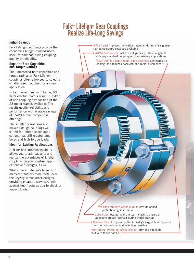
• High-strength Grade 8 Bolts provide addedprotection against failure
• Lube holes located near the tooth mesh to ensure anadequate grease reservoir during initial startup
• Massive Flex Hub provides the industry’s largest bore capacityfor the most economical selection possible
Non-turning prevailing torque locknut provides a reliablehold with fewer parts •
• 4-Point seal improves lubrication retention during misalignment;high-temperature seals are available
• AGMA bolt pattern makes Lifelign easily interchangeablewith any standard coupling on your existing applications
AGMA 20° full-depth tooth triple crowning eliminates tiploading, and reduces backlash and radial clearances •
3
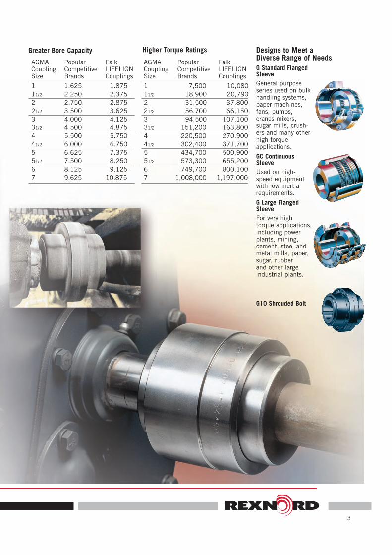
Designs to Meet aDiverse Range of NeedsG Standard FlangedSleeveGeneral purposeseries used on bulkhandling systems,paper machines,fans, pumps,cranes mixers,sugar mills, crush-ers and many otherhigh-torque applications.
GC ContinuousSleeveUsed on high-speed equipmentwith low inertiarequirements.
G Large FlangedSleeveFor very hightorque applications,including powerplants, mining,cement, steel andmetal mills, paper,sugar, rubberand other largeindustrial plants.
G10 Shrouded Bolt
AGMACouplingSize
1
11/2
2
21/2
3
31/2
4
41/2
5
51/2
6
7
PopularCompetitiveBrands
1.625
2.250
2.750
3.500
4.000
4.500
5.500
6.000
6.625
7.500
8.125
9.625
FalkLIFELIGNCouplings
1.875
2.375
2.875
3.625
4.125
4.875
5.750
6.750
7.375
8.250
9.125
10.875
Greater Bore Capacity
AGMACouplingSize
1
11/2
2
21/2
3
31/2
4
41/2
5
51/2
6
7
PopularCompetitiveBrands
7,500
18,900
31,500
56,700
94,500
151,200
220,500
302,400
434,700
573,300
749,700
1,008,000
FalkLIFELIGNCouplings
10,080
20,790
37,800
66,150
107,100
163,800
270,900
371,700
500,900
655,200
800,100
1,197,000
Higher Torque Ratings

4
Lifetime SavingsLifelign Couplings are specially
designed to remain your most
economical solution by extending
maintenance intervals, reducing
wear and increasing service life.
Advanced Lube SystemFalk Long Term Grease (LTG)
eliminates routine lubrication cycles
for up to 3 years. The location of the
lubrication hole in the sleeve
ensures that an adequate grease
reservoir will be maintained close to
the gear mesh. Plus, Lifelign’s 4-
point seal contact provides better
retention of lubricant, eliminating
the axial seal movement that can
draw lubricant out of the coupling
should misalignment occur.
For added reliability our standard
seals handle a maximum continuous
operating temperature of 250°F
(121°C) and a maximum intermit-
tent temperature of 300°F (149°C).
High temperature seals are avail-
able, extending maxi-
mum temperatures to
400°F (204°C) for con-
tinuous
duty and
500°F
(260°C)
for inter-
mittent use.
Triple crown protectionCrowning at the root, tip and face of
each tooth helps minimize wear
damage due to misalignment. This
triple-crown effect eliminates tip
loading, while also reducing
backlash and radial clearances.
Reliable, convenient fastenersHigh-strength, Grade-8 fasteners
provide added protection against
coupling failure at the flange joint.
To assure the easiest possible
assembly and disassembly, fasteners
are zinc-coated to prevent corrosion
and feature non-turning locknuts,
which allow
one-
wrench
installa-
tion with
no
washers
required.
You Get More thanCost Savings with Falk Lifelign CouplingsCapacityRexnord supplies the largest gear
couplings in the world for low-speed,
high-torque applications or where
bore capacities of 10” to 52” are
required.
QualityRexnord pours its own castings and
completely machines the
components to assure maximum
product integrity with minimum lead
times.
PerformanceRexnord can supply alloy steels for
hydraulic hub removal, increased
wear resistance, or to increase
torque ratings by an average of 60%
for only about a 30% increase in
price. The torque boost can allow
smaller sizes to be used, thus signif-
icantly reducing overall costs.
SelectionRexnord supplies a complete range
of coupling designs including, gear
disc, grid, elastomer, composite, and
fluid couplings.
ExpertiseRexnord’s extensive applications
engineering expertise combines with
our comprehensive product offering
to assure that you wind up with the
best choice for the job…. and your
preferred requirements.
Packaged System DesignRexnord’s unmatched variety of gear
drives and power transmission com-
ponents allows us to develop com-
plete packaged systems for your
power transmission needs. In many
cases, pre-packaged systems offer
drop-in installation or replacement,
minimizing installation time and
costs.
Global Availability and SupportRexnord’s has 900+ distributor loca-
tions and 300+ sales engineers,
offering local availability on a global
basis.
3-Year Heavy-Duty WarrantyRexnord rewrote industry expecta-
tions by offering the first 3-Year
Warranty, standard, on all “heavy-
duty”products.
Online SupportRexnord online support includes
spares information and pricing, serv-
ice data, product literature, quoting
tools and engineering artwork.
Falk-Rexnord Other

© Rexnord Industries, LLC, 2004, 2006. (M451-110) 5
Basic InformationInstall and operate Rexnord products in conformance withapplicable local and national safety codes and per Rexnordinstallation manuals which are available upon request. Suitableguards for rotating members may be purchased from Rexnord asoptional accessories. Consult your local Rexnord representativefor complete details.WARNING: Lock out power and remove all external loads fromthe system before attempting to service any component in thesystem. Locking out the power and removing the load will reducethe possibility of unexpected motion or reaction in the system.Falk Long Term Grease Benefits include: Increased coupling life,significantly extended re-lubrication intervals, reducedmaintenance costs, reduced downtime, superior lubrication, highload carrying capabilities and it is usable up to 121°C (250°F).
For information on Falk Long Term Grease, requestForm 840201. Lifelign gear couplings are warranted for 3 yearswhen lubricated with Falk LTG Long Term Grease.
Table of ContentsNomenclature . . . . . . . . . . . . . . . . . . . . . . . . . . . . . . . . . . . . . . . . . . 6Available Types . . . . . . . . . . . . . . . . . . . . . . . . . . . . . . . . . . . . . . . 7-9How to Select . . . . . . . . . . . . . . . . . . . . . . . . . . . . . . . . . . . . . . 10-11Quick Selection Method . . . . . . . . . . . . . . . . . . . . . . . . . . . . . . . 12-13Service Factors. . . . . . . . . . . . . . . . . . . . . . . . . . . . . . . . . . . . . . 14-15How to Order . . . . . . . . . . . . . . . . . . . . . . . . . . . . . . . . . . . . . . . . . 15
CONTINUOUS SLEEVE GEAR COUPLINGS —Dimensions & SpecificationsType GC02 Double Engagement . . . . . . . . . . . . . . . . . . . . . . . . . . . 16Type GC05 Single Engagement . . . . . . . . . . . . . . . . . . . . . . . . . . . . 17Type GC05 Floating Shaft . . . . . . . . . . . . . . . . . . . . . . . . . . . . . . . . 18
STANDARD FLANGED SLEEVE GEAR COUPLINGS —Dimensions & SpecificationsType G20 Double Engagement . . . . . . . . . . . . . . . . . . . . . . . . . . . . 19Type G32 Spacer . . . . . . . . . . . . . . . . . . . . . . . . . . . . . . . . . . . . . . 20Type G52 Single Engagement . . . . . . . . . . . . . . . . . . . . . . . . . . . . . 21Type G52 Floating Shaft . . . . . . . . . . . . . . . . . . . . . . . . . . . . . . . 22-23Type GV20 Vertical Double Engagement. . . . . . . . . . . . . . . . . . . . . . 24Type GV52 Vertical Single Engagement . . . . . . . . . . . . . . . . . . . . . . 25Types G62/G66 Brakewheel, Straight Bores & G63 Disc Brake . . . . . 26Types G62 & G66 Brakewheel, Taper Bores . . . . . . . . . . . . . . . . . . . 27Type GL20 Slide Double Engagement. . . . . . . . . . . . . . . . . . . . . . . . 28Type GL52 Slide Single Engagement. . . . . . . . . . . . . . . . . . . . . . . . . 29Type G70 Disconnect, Inching Drives . . . . . . . . . . . . . . . . . . . . . . . . 30Type G72 Disconnect . . . . . . . . . . . . . . . . . . . . . . . . . . . . . . . . . . . 31Type GP20/52/82 Insulated . . . . . . . . . . . . . . . . . . . . . . . . . . . . . . 32Type G82 Rigid . . . . . . . . . . . . . . . . . . . . . . . . . . . . . . . . . . . . . . . 33Type GV82 Rigid Thrust . . . . . . . . . . . . . . . . . . . . . . . . . . . . . . . . . 34Type GR20 Shear Pin . . . . . . . . . . . . . . . . . . . . . . . . . . . . . . . . . . . 35Type G Mill Motor & Taper Bores . . . . . . . . . . . . . . . . . . . . . . . . . . 36
Engineering DataRecommended Commercial Keys for Bores With One Key . . . . . . . . 37Shaft Diameters & Ratings for NEMA 60 Hertz & 50 HertzMetric Motors . . . . . . . . . . . . . . . . . . . . . . . . . . . . . . . . . . . . . . . . . 37Maximum Bores . . . . . . . . . . . . . . . . . . . . . . . . . . . . . . . . . . . . . . . 38Recommended Bore Tolerances, Falk Steel Coupling Hubs . . . . . . . . 38Flanged Sleeve & Rigid Hub Details . . . . . . . . . . . . . . . . . . . . . . . . . 39Puller Bolt Holes . . . . . . . . . . . . . . . . . . . . . . . . . . . . . . . . . . . . . . . 39Torsional Stiffness . . . . . . . . . . . . . . . . . . . . . . . . . . . . . . . . . . . . . . 40WR2 Values . . . . . . . . . . . . . . . . . . . . . . . . . . . . . . . . . . . . . . . . . . . 40Standard Filleted Keyways & Chamfered Keys . . . . . . . . . . . . . . . . . . 40Variable Gap . . . . . . . . . . . . . . . . . . . . . . . . . . . . . . . . . . . . . . . . . 41Misalignment Capacity . . . . . . . . . . . . . . . . . . . . . . . . . . . . . . . . . . 41
LARGE FLANGED SLEEVE GEAR COUPLINGS —Dimensions & SpecificationsType G20 Double Engagement . . . . . . . . . . . . . . . . . . . . . . . . . . . . 42Type G52 Single Engagement . . . . . . . . . . . . . . . . . . . . . . . . . . . . . 43Type G52 Floating Shaft . . . . . . . . . . . . . . . . . . . . . . . . . . . . . . . . . 44Type GV20 Vertical Double Engagement. . . . . . . . . . . . . . . . . . . . . . 45Type GV52 Vertical Single Engagement . . . . . . . . . . . . . . . . . . . . . . 46Type GL20-4 Slide Double Engagement . . . . . . . . . . . . . . . . . . . . . . 47Type G70 Disconnect, Inching Drives . . . . . . . . . . . . . . . . . . . . . . . . 48Type G82 Rigid . . . . . . . . . . . . . . . . . . . . . . . . . . . . . . . . . . . . . . . 49Type GR20 Shear Pin . . . . . . . . . . . . . . . . . . . . . . . . . . . . . . . . . . . . 50
Engineering DataRecommended Commercial Keys for Bores with One Key . . . . . . . . 51Recommended Bore Tolerances, Falk Steel Coupling Hubs . . . . . . . . 51Flanged Sleeve & Rigid Hub Details . . . . . . . . . . . . . . . . . . . . . . . . . 52Sleeve Jack Bolt Holes . . . . . . . . . . . . . . . . . . . . . . . . . . . . . . . . . . . 52Puller Bolt Holes . . . . . . . . . . . . . . . . . . . . . . . . . . . . . . . . . . . . . . . 52Torsional Stiffness . . . . . . . . . . . . . . . . . . . . . . . . . . . . . . . . . . . . . . 52WR2 Values . . . . . . . . . . . . . . . . . . . . . . . . . . . . . . . . . . . . . . . . . . . 52Bore Ranges for Reduced Shank Dia. Hubs . . . . . . . . . . . . . . . . . . . 53Puller Bolt Holes for Reduced Shank Dia. Hubs . . . . . . . . . . . . . . . . 53Standard Filleted Keyways & Chamfered Keys. . . . . . . . . . . . . . . . . . 54Misalignment Capacity . . . . . . . . . . . . . . . . . . . . . . . . . . . . . . . . . . 55
ALL TYPESRecommended Hub Bores for Interference & Clearance Fit . . . . . . 56-57Interchange Guide Flanged & Continuous Sleeve . . . . . . . . . . . . 58-59Coupling Application Data Sheet . . . . . . . . . . . . . . . . . . . . . . . . . . . 60
Selection Guide M451-110, October 2006
Copyright 2004, 2006, Rexnord Industries, LLC. All Rights Reserved. Litho in U.S.A.FALK, A-PLUS, LIFELIGN, OMNIBOX, RAM, RENEW, STEELFLEX, and ULTRAMITEare registered trademarks.Magnum Seal is a trademark of The Falk Corporation for its rotary shaft sealingsystem for enclosed gear drives.Taper-Lock is a registered trademark of a bushing under license.Viton is a registered trademark of the DuPont Co.The contents of this selection guide are subject to change without notice orobligation. Information contained herein should be confirmed before placing orders.
Factory Warranty We’re so confident in the performance andreliability of our latest generation of Falk gear drives that we’rebacking this comprehensive offering with the best standardwarranty in the business. Our full, 3-year Heavy-Duty Warrantyprovides “shaft-to-shaft” protection on all Falk components –including bearings and seals. It’s an industry first... and one morepowerful reason why Rexnord is your ultimate bottom-line driveand coupling value.�
� Warranty extends for 3 years from date of shipment.
6 (M451-110) © Rexnord Industries, LLC, 2004, 2006.
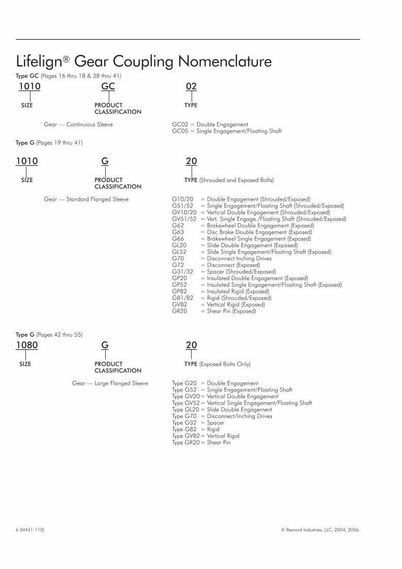
Lifelign® Gear Coupling NomenclatureType GC (Pages 16 thru 18 & 38 thru 41)
1010 GC 02
SIZE PRODUCT TYPECLASSIFICATION
Gear — Continuous Sleeve GC02 = Double EngagementGC05 = Single Engagement/Floating Shaft
Type G (Pages 19 thru 41)
1010 G 20
SIZE PRODUCT TYPE (Shrouded and Exposed Bolts)CLASSIFICATION
Gear — Standard Flanged Sleeve G10/20 = Double Engagement (Shrouded/Exposed)G51/52 = Single Engagement/Floating Shaft (Shrouded/Exposed)GV10/20 = Vertical Double Engagement (Shrouded/Exposed)GV51/52 = Vert. Single Engage./Floating Shaft (Shrouded/Exposed)G62 = Brakewheel Double Engagement (Exposed)G63 = Disc Brake Double Engagement (Exposed)G66 = Brakewheel Single Engagement (Exposed)GL20 = Slide Double Engagement (Exposed)GL52 = Slide Single Engagement/Floating Shaft (Exposed)G70 = Disconnect Inching DrivesG72 = Disconnect (Exposed)G31/32 = Spacer (Shrouded/Exposed)GP20 = Insulated Double Engagement (Exposed)GP52 = Insulated Single Engagement/Floating Shaft (Exposed)GP82 = Insulated Rigid (Exposed)G81/82 = Rigid (Shrouded/Exposed)GV82 = Vertical Rigid (Exposed)GR20 = Shear Pin (Exposed)
Type G (Pages 42 thru 55)
1080 G 20
SIZE PRODUCT TYPE (Exposed Bolts Only)CLASSIFICATION
Gear — Large Flanged Sleeve Type G20 = Double EngagementType G52 = Single Engagement/Floating ShaftType GV20= Vertical Double EngagementType GV52= Vertical Single Engagement/Floating ShaftType GL20 = Slide Double EngagementType G70 = Disconnect/Inching DrivesType G32 = SpacerType G82 = RigidType GV82= Vertical RigidType GR20= Shear Pin
© Rexnord Industries, LLC, 2004, 2006. (M451-110) 7
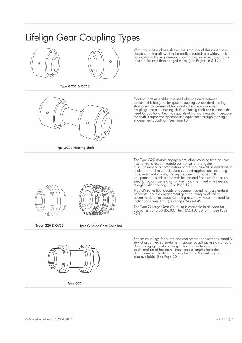
Type GC02 & GC05
With two hubs and one sleeve, the simplicity of this continuoussleeve coupling allows it to be easily adapted to a wide variety ofapplications. It’s very compact, low in rotating mass, and has alower initial cost than flanged types. (See Pages 16 & 17.)
Type GC05 Floating Shaft
Floating shaft assemblies are used when distance betweenequipment is too great for spacer couplings. A standard floatingshaft assembly consists of two standard single engagementcouplings and a connecting shaft. A floating shaft can eliminate theneed for additional bearing supports along spanning shafts becausethe shaft is supported by connected equipment through the singleengagement couplings. (See Page 18.)
The Type G20 double engagement, close coupled type has twoflex halves to accommodate both offset and angularmisalignment or a combination of the two, as well as end float. Itis ideal for all horizontal, close coupled applications includingfans, overhead cranes, conveyors, steel and paper millequipment. It is adaptable with limited end float kits for use onelectric motors, generators or any machines fitted with sleeve orstraight roller bearings. (See Page 19.)
Type GV20 vertical double engagement coupling is a standardhorizontal double engagement gear coupling modified toaccommodate the sleeve centering assembly. Recommended forinclinations over 10°. (See Pages 24 and 45.)
The Type G Large Gear Coupling is available in all types forcapacities up to 8,185,000 Nm, (72,450,00 lb-in. (See Page42.)
Types G20 & GV20
Spacer couplings for pump and compressor applications simplifyservicing connected equipment. Spacer couplings use a standarddouble engagement coupling with a spacer tube and anadditional set of fasteners. Stock spacer lengths for quickdelivery are available in the popular sizes. Special lengths arealso available. (See Page 20.)
Type G32
Lifelign Gear Coupling Types
Type G Large Gear Coupling

8 (M451-110) © Rexnord Industries, LLC, 2004, 2006.
Floating shaft assemblies are used when distance betweenequipment is too great for spacer couplings. A standard floatingshaft assembly consists of two standard single engagementcouplings, two gap discs and a connecting shaft. A floating shaft caneliminate the need for additional bearing supports along spanningshafts because the shaft is supported by connected equipmentthrough the single engagement couplings. (See Pages 22 and 44.)When used with a vertical floating shaft on inclinations over 10°,the Type GV52 coupling is used as the lower coupling to supportthe shaft. (See Pages 25 and 46.)
Flex Hubs on Floating Shaft (RFFR) — Assembly of the flex hubson the floating shaft allows for easier replacement and allows therigid hubs with greater bore capacity to be used on theconnected equipment shafts. This frequently means a smallercoupling size can be utilized.
Rigid Hubs on Floating Shaft (FRRF) — When the rigid hubs areon the floating shaft, shorter shaft spans can be accommodated,since no cover drawback is required.
Types G52 & GV52 Floating Shaft
Double or single engagement brakewheel and disc brakecouplings are used for applications, such as cranes, hoists andconveyors. Brakewheel and disc brake couplings accommodatemisalignment between connected equipment and eliminate theneed for double shaft extensions on motors and gear drives forapplications requiring brakes. (See Pages 26 & 27.)
Types G62 & 66 Type G63
The Type G52 single engagement design is used with floatingshafts or three bearing drive trains. It has one flex half and onerigid half and only accepts angular misalignment. (See Pages21and 43.)
The GV52 vertical single engagement gear coupling is astandard horizontal single engagement gear coupling modifiedto accommodate the sleeve centering assembly. It recommendedfor inclinations over 10°. Downward thrust capacity for Sizes1010 thru 1030GV52 is 1 130 Nm; Sizes 1035 thru 1070GV52is 3 390 Nm and Sizes 1080GV52 and larger is 9 830 Nm. (SeePages 25 & 46.)
Types G52 & GV52
Types GL20 & GL52
Double and single engagement Slide couplings are used forapplications requiring axial movement to accommodate thermalshaft expansion or adjustment. (See Pages 28, 29, and 47.)

© Rexnord Industries, LLC, 2004, 2006. (M451-110) 9
INSULATORPLATE
Types GP20, GP52 & GP82
Double, single or rigid engagement insulated couplings are usedto eliminate the flow of stray current from one shaft to anotherand to protect sensitive electrical equipment. They are notintended to withstand high potential currents, short circuits orstatic charges. Insulated couplings consist of standard hubs andsleeves, and utilize reduced diameter socket head cap screws.The insulator plate is made of a NEMA Grade LE phenolicmaterial and insulator bushings and washers are made of NEMAGrade G9 phenolic material. (See Page 32.)
Type G70 Disconnect couplings are used for low speed applicationsthat require quick disconnect of equipment or inching drives. It isused for occasional servicing or inspection of drive systemcomponents and is most commonly used on portable or stationaryinching drive systems where the driving end hub/sleeve combinationis mounted on the driving shaft on the incher for connecting ordisconnecting at standstill. (See Pages 30 and 48.)
Type G72 Disconnect couplings were designed for higher speedapplications that require quick disconnect such as backup drives.When the long flex hub is mounted on the auxiliary driving shaft,the changeover is performed at standstill by engaging the freerunning hub. (See Page 31.)
Types G70 & G72
Type G82
SHEARPLATES
HARDENEDBUSHING
SHEAR PIN
SHEAR NOTCHDIAMETER
Shear pin couplings are used for applications subject to jammingand overload. When pins break, the equipment is physicallydisconnected preventing damage. If desired shear settings areunknown, the selection should be referred to the Factory. (See Pages35 and 50.)
Type GR20
Rigid couplings are used when there is no need to accommodatemisalignment, and where thrust loads are generated such asvertical mixer applications. (See Pages 33, 34, and 49.)

10 (M451-110) © Rexnord Industries, LLC, 2004, 2006.
How to Select
Standard Selection MethodThe standard selection method can be used for most motor,turbine, or engine driven applications. The following informationis required to select a gear coupling.
�Kilowatt (kW) or torque (Nm)
� Running rpm.
�Application or type of equipment to be connected (motor topump, drive to conveyor, etc.).
� Shaft diameters.
� Shaft gaps.
� Physical space limitations
� Special bore or finish information and type of fit
Exceptions are High Peak Loads, Brake Applications or highfrequency axial sliding (greater than 5 per hour). For theseconditions, use the Formula Selection Method on the nextpage. Applications that require rapid changes in directionor torque reversals should be referred to Falk.1. RATING: Determine system torque. If torque is not given,
calculate as shown below.
System Torque (Nm) =kW x 9549
rpm
Where: kW (Kilowatt) is the actual or transmitted powerrequired by the application (if unknown, use the motor orturbine nameplate rating) and rpm is the actual speed thecoupling is rotating.
2. SERVICE FACTOR: Determine the appropriate service factorfrom Tables 4 and 5, Page14, or Table 6, Page 15.
3. REQUIRED MINIMUM COUPLING RATING: Determine therequired minimum coupling rating as shown below
Minimum Coupling Rating = S.F. (Service Factor) x Torque(Nm)
4. TYPE: Refer to Pages 7-9 and select the appropriate coupling type.
5. SIZE: Determine proper size of type selected from Table 1 bytracing down torque column to a value that is equal or greaterthan that determined in Step 3 above. Then turn to thedimension pages of appropriate coupling type selected andcheck the following for the size selected.
6. Check: Coupling Capacities and Dimensions
A. Bores — Check shaft diameters against coupling maximumbore. If bore is inadequate, consider the use of a reducedkey from engineering tables, or select a larger size coupling.
B. Speeds (rpm) — Check the operating rpm against thecoupling allowable speed. If catalogued values areinadequate, consider balancing. Balancing may allow up to50% increase in speeds shown. Contact the Factory withcomplete application details.
C. Dimensions — Checks are: length of hubs and alignmentclearances against shaft lengths, outside diameter ofcoupling against radial clearances
STANDARD SELECTION EXAMPLE:
Select a gear coupling to connect a 350 kW 1000 rpm electricmotor to a drive high speed shaft of a maneuvering winch.Maximum shaft separation is 6 mm. Motor shaft diameter is 85mm and key is 22 mm x 14 mm. Winch shaft diameter is 75 mmand key is 20 mm x 12 mm. Motor and winch extensions areboth 150 mm long.
1. DETERMINE REQUIRED RATING:
System Torque (Nm) =350 kW x 9549
1000rpm�3342
2. SERVICE FACTOR: From Service Factor Table 4, Page 14 =1.5
3. REQUIRED MINIMUM COUPLING RATING:1.5 x 3342 Nm = 5013 Nm
4. TYPE: From Page 7, to connect close coupled shafts (6 mmgap) the double engagement Type 1025GC02 or Type1025G20 coupling is the selection. Refer to Pages 14 or 17 fordimensions.
5. SIZE: From Page 16, a Size 1025GC02 or Page 19, a Size1025G20 is the proper selection based on a torque rating of7 470 Nm exceeding the required minimum coupling rating of5013 Nm.
6. CHECK: Maximum speed capacity of 3,330 (1025GC02) and5000 (1025G20) rpm exceeds required speed of 1000 rpm.Maximum bore capacity of 98 mm exceeds the actual shaftdiameters.
TABLE 1 — Torque and Horsepower Ratings
Coupling Size Torque Rating (Nm) kW per 100 RPM
1010G/GC 1 140 11,91015G/GC 2 350 24,61020G/GC 4 270 44,71025G/GC 7 470 78,31030G/GC 12 100 1271035G/GC 18 500 194
1040G 30 600 3211045G 42 000 4401050G 56 600 5931055G 74 000 7751060G 90 400 9471070G 135 000 1 420
CouplingTorque Rating (Nm) x103 kW per 100 RPM
1000 Series 2000 Series 1000 Series 2000 Series
1080G 2080G 170 234 1 780 2 4501090G 2090G 226 315 2 360 3 3001100G 2100G 310 443 3 250 4 6401110G 2110G 413 609 4 320 6 3801120G 2120G 555 777 5 810 8 1401130G 2130G 719 925 7 530 9 690
1140G 2140G 911 1 140 9 540 11 9001150G 2150G 1 100 1 350 11 500 14 2001160G 2160G 1 310 1 640 13 700 17 1001180G 2180G 1 660 2 140 17 400 22 4001200G 2200G 2 140 2 850 22 400 29 8001220G 2220G 2 720 3 560 28 500 37 300
1240G 2240G 3 470 4 480 36 400 47 0001260G 2260G 4 490 5 480 47 000 57 4001280G 2280G 5 840 6 760 61 100 70 8001300G 2300G 6 760 8 190 70 800 85 700
© Rexnord Industries, LLC, 2004, 2006. (M451-110) 11
How to Select
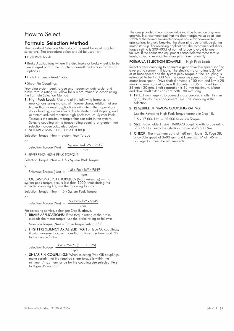
Formula Selection MethodThe Standard Selection Method can be used for most couplingselections. The procedure below should be used for:
�High Peak Loads
�Brake Applications (where the disc brake or brakewheel is to bean integral part of the coupling, consult the Factory for designoptions.)
�High Frequency Axial Sliding
� Shear Pin Couplings
Providing system peak torque and frequency, duty cycle, andbrake torque rating will allow for a more refined selection usingthe Formula Selection Method.1. High Peak Loads: Use one of the following formulas for
applications using motors, with torque characteristics that arehigher than normal; applications with intermittent operations,shock loading, inertia effects due to starting and stopping andor system induced repetitive high peak torques. System PeakTorque is the maximum torque that can exist in the system.Select a coupling with a torque rating equal to or greater thanselection torque calculated below.
A. NON-REVERSING HIGH PEAK TORQUE
Selection Torque (Nm) = System Peak Torque
or
Selection Torque (Nm) =System Peak kW x 9549
rpm
B. REVERSING HIGH PEAK TORQUE
Selection Torque (Nm) = 1.5 x System Peak Torque
or
Selection Torque (Nm) =1.5 x Peak kW x 9549
rpm
C. OCCASIONAL PEAK TORQUES (Non-Reversing) — If asystem peak torque occurs less than 1000 times during theexpected coupling life, use the following formula:
Selection Torque (Nm) = .5 x System Peak Torque
or
Selection Torque (Nm) =.5 x Peak kW x 9549
rpm
For reversing service, select per Step B, above.2. BRAKE APPLICATIONS: If the torque rating of the brake
exceeds the motor torque, use the brake rating as follows:
Selection Torque (Nm) = Brake Torque Rating x S.F.
3. HIGH FREQUENCY AXIAL SLIDING: For Type GL couplings;if axial movement occurs more than 5 times per hour, add .25to the service factor.
Selection TorquekW x 9549 x (S.F. + .25)
rpm
4. SHEAR PIN COUPLINGS: When selecting Type GR couplings,make certain that the required shear torque is within theminimum/maximum range for the coupling size selected. Referto Pages 35 and 50.
The user provided shear torque value must be based on a systemanalysis. It is recommended that the shear torque value be at least225% of the normal transmitted torque value for non-reversingapplications to avoid breaking the shear pins due to fatigue duringmotor start-up. For reversing applications, the recommended sheartorque setting is 300-400% of normal torque to avoid fatiguefailures. If the connected equipment cannot tolerate these torquelevels, expect to replace the shear pins more frequently.
FORMULA SELECTION EXAMPLE — High Peak Load:
Select a gear coupling to connect a gear drive low speed shaft toa reversing runout mill table. The electric motor rating is 37 kWat its base speed and the system peak torque at the coupling isestimated to be 17 000 Nm The coupling speed is 77 rpm at themotor base speed. Drive shaft diameter is 100 mm and key is 28mm x 16 mm. Runout table roll diameter is 135 mm and key is36 mm x 20 mm. Shaft separation is 12 mm maximum. Motorand drive shaft extensions are both 180 mm long.1. TYPE: From Page 7, to connect close coupled shafts (12 mm
gap), the double engagement Type G20 coupling is theselection.
2. REQUIRED MINIMUM COUPLING RATING:
Use the Reversing High Peak Torque formula in Step 1B.
1.5 x 17 000 Nm = 25 500 Selection Torque
3. SIZE: From Table 1, Size 1040G20 coupling with torque ratingof 30 600 exceeds the selection torque of 25 500 Nm
4. CHECK: The maximum bore of 160 mm, Table 13, Page 38,allowable speed of 3600 rpm and Dimension M of 145 mm,on Page 17, meet the requirements.
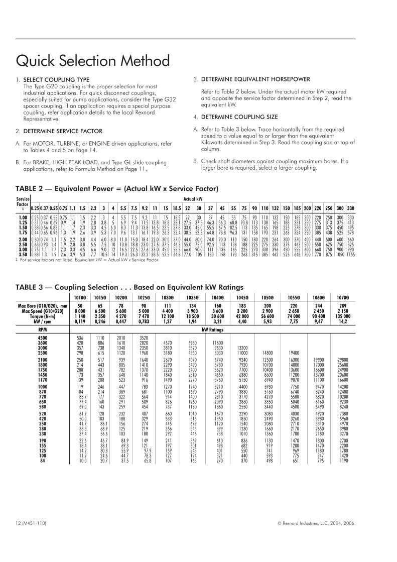
Quick Selection Method1. SELECT COUPLING TYPE
The Type G20 coupling is the proper selection for mostindustrial applications. For quick disconnect couplings,especially suited for pump applications, consider the Type G32spacer coupling. If an application requires a special purposecoupling, refer application details to the local RexnordRepresentative.
2. DETERMINE SERVICE FACTOR
A. For MOTOR, TURBINE, or ENGINE driven applications, referto Tables 4 and 5 on Page 14.
B. For BRAKE, HIGH PEAK LOAD, and Type GL slide couplingapplications, refer to Formula Method on Page 11.
3. DETERMINE EQUIVALENT HORSEPOWER
Refer to Table 2 below. Under the actual motor kW requiredand opposite the service factor determined in Step 2, read theequivalent kW.
4. DETERMINE COUPLING SIZE
A. Refer to Table 3 below. Trace horizontally from the requiredspeed to a value equal to or larger than the equivalentKilowatts determined in Step 3. Read the coupling size at top ofcolumn.
B. Check shaft diameters against coupling maximum bores. If alarger bore is required, select a larger coupling.
12 (M451-110) © Rexnord Industries, LLC, 2004, 2006.
TABLE 2 — Equivalent Power = (Actual kW x Service Factor)
ServiceFactor
‡
Actual kW
0.25 0.37 0.55 0.75 1.1 1.5 2.2 3 4 5.5 7.5 9.2 11 15 18.5 22 30 37 45 55 75 90 110 132 150 185 200 220 250 300 330
1.00 0.25 0.37 0.55 0.75 1.1 1.5 2.2 3 4 5.5 7.5 9.2 11 15 18.5 22 30 37 45 55 75 90 110 132 150 185 200 220 250 300 3301.25 0.31 0.46 0.69 0.9 1.4 1.9 2.8 3.8 5 6.9 9.4 11.5 13.8 18.8 23.1 27.5 37.5 46.3 56.3 68.8 93.8 113 138 165 188 231 250 275 313 375 4131.50 0.38 0.56 0.83 1.1 1.7 2.3 3.3 4.5 6.0 8.3 11.3 13.8 16.5 22.5 27.8 33.0 45.0 55.5 67.5 82.5 113 135 165 198 225 278 300 330 375 450 4951.75 0.44 0.65 0.96 1.3 1.9 2.6 3.9 5.3 7.0 9.6 13.1 16.1 19.3 26.3 32.4 38.5 52.5 64.8 78.8 96.3 131 158 193 231 263 324 350 385 438 525 578
2.00 0.50 0.74 1.1 1.5 2.2 3.0 4.4 6.0 8.0 11.0 15.0 18.4 22.0 30.0 37.0 44.0 60.0 74.0 90.0 110 150 180 220 264 300 370 400 440 500 600 6602.50 0.63 0.93 1.4 1.9 2.8 3.8 5.5 7.5 10 13.8 18.8 23.0 27.5 37.5 46.3 55.0 75.0 92.5 113 138 188 225 275 330 375 463 500 550 625 750 8253.00 0.75 1.1 1.7 2.3 3.3 4.5 6.6 9.0 12 16.5 22.5 27.6 33.0 45.0 55.5 66.0 90.0 111 135 165 225 270 330 396 450 555 600 660 750 900 9903.50 0.88 1.3 1.9 2.6 3.9 5.3 7.7 10.5 14 19.3 26.3 32.2 38.5 52.5 64.8 77.0 105 130 158 193 263 315 385 462 525 648 700 770 875 1050 1155
‡ For service factors not listed. Equivalent kW = Actual kW x Service Factor.
TABLE 3 — Coupling Selection . . . Based on Equivalent kW Ratings
1010G 1015G 1020G 1025G 1030G 1035G 1040G 1045G 1050G 1055G 1060G 1070G
Max Bore (G10/G20), mmMax Speed (G10/G20)
Torque (N-m)kW / rpm
508 0001 1400,119
656 5002 3500,246
785 6004 2700,447
985 0007 4700,783
1114 400
12 1001,27
1343 900
18 5001,94
1603 600
30 6003,21
1833 200
42 0004,40
2002 900
56 6005,93
2202 650
74 0007,75
2442 450
90 4009,47
2892 150
135 00014,2
RPM kW Ratings
4500 536 1110 2010 35203600 428 886 1610 2820 4570 6980 116003000 357 738 1340 2350 3810 5820 9630 132002500 298 615 1120 1960 3180 4850 8030 11000 14800 19400
2100 250 517 939 1640 2670 4070 6740 9240 12500 16300 19900 298001800 214 443 805 1410 2290 3490 5780 7920 10700 14000 17000 256001750 208 431 782 1370 2220 3400 5620 7700 10400 13600 16600 249001450 173 357 648 1140 1840 2810 4650 6380 8600 11200 13700 206001170 139 288 523 916 1490 2270 3760 5150 6940 9070 11100 16600
1000 119 246 447 783 1270 1940 3210 4400 5930 7750 9470 14200870 104 214 389 681 1100 1690 2790 3830 5160 6740 8240 12400720 85.7 177 322 564 914 1400 2310 3170 4270 5580 6820 10200650 77.4 160 291 509 826 1260 2090 2860 3850 5040 6160 9230580 69.0 143 259 454 737 1130 1860 2550 3440 4500 5490 8240
520 61.9 128 232 407 660 1010 1670 2290 3080 4030 4920 7380420 50.0 103 188 329 533 815 1350 1850 2490 3260 3980 5960350 41.7 86.1 156 274 445 679 1120 1540 2080 2710 3310 4970280 33.3 68.9 125 219 356 543 899 1230 1660 2170 2650 3980230 27.4 56.6 103 180 292 446 738 1010 1360 1780 2180 3270
190 22.6 46.7 84.9 149 241 369 610 836 1130 1470 1800 2700155 18.4 38.1 69.3 121 197 301 498 682 919 1200 1470 2200125 14.9 30.8 55.9 97.9 159 243 401 550 741 969 1180 1780100 11.9 24.6 44.7 78.3 127 194 321 440 593 775 947 142084 10.0 20.7 37.5 65.8 107 163 270 370 498 651 795 1190

C. Check the required speed against the allowable speed of thecoupling selected. If a higher speed is required, refer completedetails to the local Rexnord Representative.
D. Check dimensions . . . Dimension M in particular.
EXAMPLE:Select a gear coupling to connect the low speed shaft of a gear drive to abelt conveyor. The motor is 250 kW and the low speed shaft RPM is 68.The gear drive shaft is 160 mm and the conveyor shaft is 180 mm.
SELECTION:
1. To connect close coupled shafts and to accommodateanticipated shaft misalignment, the double engagement TypeG20 coupling shown on Page 19, is the selection.
2. From Table 4 on Page 14, the service factor is 1.0.
3. From Table 2, Page 12, the equivalent power is 250 kW.
4. From Table 3 below, the coupling size is 1045G for 68 rpm.From the table on Page 19, the maximum bore of 183 mm,and allowable speed of 3200 rpm are all satisfactory. Checkother dimensional information on Page 19 against theavailable shaft lengths, shaft gaps, and diameter restrictions.
© Rexnord Industries, LLC, 2004, 2006. (M451-110) 13
TABLE 3 — Coupling Selection . . . Based on Equivalent kW Ratings (Continued)
1010G 1015G 1020G 1025G 1030G 1035G 1040G 1045G 1050G 1055G 1060G 1070G
Max Bore (G10/G20) mmMax Speed (G10/G20)
Torque (N-m)kW / rpm
508 0001 1400,119
656 5002 3500,246
785 6004 2700,447
985 0007 4700,783
1114 400
12 1001,27
1343 900
18 5001,94
1603 600
30 6003,21
1833 200
42 0004,40
2002 900
56 6005,93
2202 650
74 0007,75
2442 450
90 4009,47
2892 150
135 00014,2
RPM kW Ratings
68 8.09 16.7 30.4 53.2 86.4 132 218 299 403 527 644 96656 6.66 13.8 25.0 43.8 71.1 109 180 246 332 434 530 79545 5.36 11.1 20.1 35.2 57.2 87.3 144 198 267 349 426 63937 4.40 9.10 16.5 29.0 47.0 71.8 119 163 219 287 350 52530 3.57 7.38 13.4 23.5 38.1 58.2 96.3 132 178 233 284 426
25 2.98 6.15 11.2 19.6 31.8 48.5 80.3 110 148 194 237 35520 2.38 4.92 8.94 15.7 25.4 38.8 64.2 88.0 119 155 189 28416.5 1.96 4.06 7.38 12.9 21.0 32.0 53.0 72.6 97.8 128 156 23413.5 1.61 3.32 6.03 10.6 17.1 26.2 43.3 59.4 80.1 105 128 19211 1.31 2.71 4.92 8.61 14.0 21.3 35.3 48.4 65.2 85.3 104 156
9 1.07 2.21 4.02 7.05 11.4 17.5 28.9 39.6 53.4 69.8 85.2 1287.5 0.893 1.85 3.35 5.87 9.53 14.6 24.1 33.0 44.5 58.1 71.0 1075 0.595 1.23 2.24 3.92 6.35 9.70 16.1 22.0 29.7 38.8 47.4 71.0
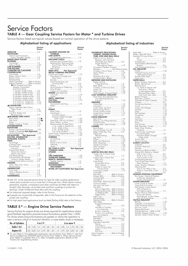
Service Factors
14 (M451-110) © Rexnord Industries, LLC, 2004, 2006.
TABLE 4 — Gear Coupling Service Factors for Motor � and Turbine Drives
Service factors listed are typical values based on normal operation of the drive systems.
AERATOR .......................................2,0AGITATORS
Vertical and HorizontalScrew, Propeller, Paddle ............1,0
BARGE HAUL PULLER ...................1,5BLOWERS
Centrifugal....................................1,0Lobe or Vane ................................1,25
CAR DUMPERS...............................2.5CAR PULLERS .................................1,5CLARIFIER OR CLASSIFIER ...........1,0COMPRESSORS
Centrifugal....................................1,0Rotary, Lobe or Vane.....................1,25Rotary, Screw ................................1,0ReciprocatingDirect Connected.......... Refer to FactoryWithout Flywheel........... Refer to Factory
�With Flywheel and Gearbetween Compressorand Prime Mover1 cylinder, single acting..........3,01 cylinder, double acting ........3,02 cylinders, single acting ........3,02 cylinders, double acting.......3,03 cylinders, single acting ........3,03 cylinders, double acting.......2,04 or more cly., single act. .......1,754 or more cyl., double act. .....1,75
�CONVEYORSApron, Assembly, Belt, Chain,
Flight, Screw..............................1,0Bucket ..........................................1,25Live Roll, Shaker and
Reciprocating ............................3,0��CRANES AND HOIST
Main Hoist..................................1,75�Skip Hoist....................................1,75�Slope............................................1,5Bridge, Travel or Trolley ................1,75
DYNAMOMETER ............................1,0ELEVATORS
Bucket, Centrifugal Discharge........1,25Freight or PassengerNot ApprovedGravity Discharge .........................1,25
ESCALATORS Not ApprovedEXCITER, GENERATOR.................. 1,0EXTRUDER, PLASTIC...................... 1,5FANS
Centrifugal....................................1,0Cooling Tower ..............................2,0Forced Draft — Across the
Line start ...................................1,5Forced Draft Motor
Driven thru fluid orelectric slip clutch ......................1,0
Gas Recirculating..........................1,5Induced Draft with damper
control or blade cleaner.............1,25Induced Draft without controls .......2,0
FEEDERSApron, Belt, Disc, Screw ................1,0Reciprocating................................2.5
GENERATORSEven Load.....................................1,0Hoist or Railway Service.................1,5Welder Load .................................2,0
HAMMERMILL ................................1,75
LAUNDRY WASHER ORTUMBLER ....................................2,0
LINE SHAFTSAny Processing Machinery .............1,5
MACHINE TOOLSAuxiliary and Traverse Drive...........1,0Bending Roll, Notching Press,
Punch Press, Planer, PlateReversing...................................1,75
Main Drive....................................1,5MAN LIFTS Not ApprovedMETAL FORMING MACHINESContinuous Caster............................1,75
Draw Bench Carriage andMain Drive ................................2,0
Extruder ........................................2,0Farming Machine and
Forming Mills ............................2,0Slitters...........................................1,0Wire Drawing or Flattening............1,75Wire Winder .................................1,5Coilers and Uncoilers ....................1,5
MIXERS (see Agitators)Concrete.......................................1,75Muller...........................................1,5
PRESS, PRINTING ..........................1,5PUG MILL .......................................1,75PULVERIZERS
Hammermill and Hog....................1,75Roller............................................
1,5PUMPS
Boiler Feed ...................................1,5Centrifugal —
Constant Speed .........................1,0Frequent Speed Changes
under Load ............................1,25Descaling, with accumulators ........1,25Gear, Rotary, or Vane ...................1,25Reciprocating, Plunger Piston
1 cyl., single or double act.........3,02 cyl., single acting....................2,02 cyl., double acting ..................1,753 or more cylinders....................1,5
Screw Pump, Progressing Cavity ........1,25Vacuum Pump ..................................1,25SCREENS
Air Washing ..................................1,0Grizzly ..........................................2,0Rotary Coal or Sand......................1,5Vibrating.......................................2.5Water ...........................................1,0
SKI TOWS & LIFTS Not ApprovedSTEERING GEAR ............................1,0STOKER ..........................................1,0TIRE SHREDDER.............................1,50TUMBLING BARREL .......................1,75WINCH, MANEUVERING
Dredge, Marine ............................1,5WINDLASS .....................................1,5WOODWORKING
MACHINERY ...............................1,0WORK LIFT PLATFORMS Not Approved
Alphabetical listing of applicationsService ServiceFactor Factor
Service ServiceFactor Factor
Alphabetical listing of industries
� Add .25 to the required service factor for Type GL slide coupling applicationswhere axial movement occurs more than 5 times per hour. When electric motors,generators, engines, compressors and other machines are fitted with sleeve orstraight roller bearings, use limited axial end float couplings to protect thebearings. Order limited end float discs with the coupling.
� For balanced opposed design, refer to the Factory.
� If people are occasionally transported, refer to the Factory for the selection of theproper size coupling.
� For high peak load applications (such as Metal Rolling Mills) refer to the Factory.
TABLE 5 � — Engine Drive Service Factors
Service Factors for engine drives are those required for applications wheregood flywheel regulation prevents torque fluctuations greater than ±20%.For drives where torque fluctuations are greater or where the operation isnear a serious critical or torsional vibration, a mass elastic study is necessary.
No. of Cylinders 4 or 5 � 6 or more �
Table 1 S.F. 1,0 1,25 1,5 1,75 2,0 2,5 1,0 1,25 1,5 1,75 2,0 2,5
Engine S.F. 2,0 2,25 2,5 2,75 3,0 3,5 1,5 1,75 2,0 2,25 2,5 3,0
� To use Table 5, first determine application service factor from Table 4. Use thatfactor to determine ENGINE Service Factor from Table 5. When service factorfrom Table 4 is greater than 2.5, refer complete application details to theFactory for engineering review.
AGGREGATE PROCESSING,CEMENT, MINING KILNS;TUBE, ROD AND BALL MILLSDirect or on L.S. shaft of
Reducer, with final driveMachined Spur Gears ................2,0Single Helical or
Herringbone Gears ................1,75Conveyors, Feeders, Screens,Elevators.......................See General ListingCrushers, Ore or Stone .................2,5Dryer, Rotary.................................1,75Grizzly ..........................................2,0Hammermill or Hog ......................1,75Tumbling Mill or Barrel..................1,75
BREWING AND DISTILLINGBottle and Can
Filling Machines ........................1,0Brew Kettle....................................1,0Cookers, Continuous Duty.............1,25Lauter Tub ....................................1,5Mash Tub .....................................1,25Scale Hopper, Frequent Peaks .......1,75
CLAY WORKING INDUSTRYBrick Press, Briquette Machine,
Clay Working Machine,Pug Mill ....................................1,75
DREDGESCable Reel ....................................1,75Conveyors ....................................1,25Cutter head, Jig Drive ...................2,0Maneuvering Winch ......................1,5Pumps (uniform load) ....................1,5Screen Drive, Stacker ....................1,75Utility Winch .................................1,5
FOOD INDUSTRYBeet Slicer.....................................1,75Bottling, Can Filling Machine ........1,0Cereal Cooker ..............................1,25Dough Mixer, Meat Grinder ..........1,75
LUMBERBand Resaw ..................................1,5Circular Resaw, Cut-off .................1,75Edger, Head Rig, Hog ...................2,0Gang Saw
(Reciprocating) ........ Refer to FactoryLog Haul.......................................2,0Planer...........................................1,75Rolls, Non-Reversing .....................1,25Rolls, Reversing .............................2,0Sawdust Conveyor.........................1,25Slab Conveyor ..............................1,75Sorting Table ................................1,5Trimmer ........................................1,75
�METAL ROLLING MILLSCoilers (Up or Down) Cold
Mills only...................................1,5Coilers (Up or Down) Hot
Mills only...................................2,0Coke Plants
Pusher Ram Drive ......................2,5Door Opener ............................2,0Pusher or Larry Car
Traction Drive ........................3,0Continuous Caster ........................1,75Cold Mills —Strip Mills ....................Refer to FactoryTemper Mills ................Refer to FactoryCooling Beds ................................1,5Drawbench ...................................2,0Feed Rolls - Blooming Mills ...........3,0Furnace Pushers ............................2,0Hot and Cold Saws .......................2,0Hot Mills —
Strip or Sheet Mills ....Refer to FactoryReversing Blooming ..Refer to Factoryor Slabbing Mills ......Refer to FactoryEdger Drives.............Refer to Factory
Ingot Cars.....................................2,0Manipulators.................................3,0Merchant Mills .............Refer to FactoryMill Tables
Roughing BreakdownMills ......................................3,0
Hot Bed or Transfer,non-reversing.........................1,5
. Runout, reversing.......................3,0Runout, non-reversing,
non-plugging .........................2,0Reel Drives....................................1,75Rod Mills ......................Refer to FactoryScrewdown ...................................2,0Seamless Tube Mills
Piercer.......................................3,0Thrust Block...............................2,0Tube Conveyor Rolls ..................2,0Reeler .......................................2,0Kick Out....................................2,0
Shear Croppers ...............Refer to FactorySideguards .......................................3.0
Skelp Mills ......................Refer to FactorySlitters, Steel Mill Only ......................1.75Soaking Pit Cover Drives —
Lift ............................................1,0Travel........................................2,0
Straighteners .................................2,0Unscramblers (Billet Bundle
Busters) .....................................2,0Wire Drawing Machinery ...............1,75
OIL INDUSTRYChiller ..........................................1,25Oilwell Pumping (not over
150% peak torque) ....................2,0Paraffin Filter Press ........................1,5Rotary Kiln ....................................2,0
PAPER MILLSBarker Auxiliary, Hydraulic.............2,0Barker, Mechanical .......................2,0Barking Drum
L.S. shaft of reducer withfinal drive - Helicalor Herringbone Gear .............2,0Machined Spur Gear..............2,5Cast Tooth Spur Gear ............3,0
Beater & Pulper .............................1,75Bleachers, Coaters ........................1,0Calender & Super Calender...........1,75Chipper ........................................2,5Converting Machine......................1,25Couch ..........................................1,75Cutter, Felt Whipper ......................2,0Cylinder........................................1,75Dryer ............................................1,75Felt Stretcher .................................1,25Fourdrinier ....................................1,75Jordan ..........................................2,0Log Haul.......................................2,0Line Shaft......................................1,5Press.............................................1,75Pulp Grinder .................................1,75Reel, Rewinder, Winder .................1,5Stock Chest, Washer,
Thickener ..................................1,5Stock Pumps, Centrifugal
Constant Speed .........................1,0Frequent Speed Changes
Under Load............................1,25Suction Roll...................................1,75Vacuum Pumps .............................1,25
RUBBER INDUSTRYCalender ......................................2,0Cracker, Plasticator .......................2,5Extruder ........................................1,75Intensive or Banbury Mixer.............2,5Mixing Mill, Refiner or Sheeter
One or two in line .....................2,5Three or four in line ...................2,0Five or more in line....................1,75
Tire Building Machine....................2,5Tire & Tube Press Opener
(Peak Torque) ............................1,0Tuber, Strainer, Pelletizer ...............1,75Warming Mill
One or two Mills in line .............2,0Three or more Mills in line .........1,75
Washer .........................................2,5SEWAGE DISPOSAL EQUIPMENT
Bar Screen, Chemical Feeders,Collectors, DewateringScreen, Grit Collector ................1,0
SUGAR INDUSTRYCane Carrier & Leveler..................1,75Cane Knife & Crusher ...................2,0Mill Stands, Turbine Driver
With all helical orHerringbone gears.....................1,5
Electric Drive or Steam EngineDrive with Helical,Herringbone, or Spur Gearswith any Prime Mover.................1,75
TEXTILE INDUSTRYBatcher .........................................1,25Calender, Card Machine...............1,5Cloth Finishing Machine................1,5Dry Can, Loom .............................1,5Dyeing Machinery .........................1,25Knitting Machine.....Refer to FalkMangle, Napper, Soaper...............1,25Spinner, Tenter Frame, Winder ......1,5

© Rexnord Industries, LLC, 2004, 2006. (M451-110) 15
Typical applications forelectric motor or
turbine driven equipment
TypicalServiceFactor
Constant Torque such asCentrifugal Pumps, Blowers,and Compressors.
1.0
Continuous duty with sometorque variations includingExtruders, Forced Draft Fans.
1.5
Light shock loads fromBriquetting Machine, RubberCalender, or Crane and Hoist.
2.0
Moderate shock loading asexpected from a Car Dumper,Ball Mill, or Vibrating Screen.
2.5
Heavy shock load with somenegative torques fromCrushers, Hammer Mill, andBarking Drum.
3.0
Applications likeReciprocating Compressorswith frequent torque reversals,which do not necessarily causereverse rotations.
ConsultRexnord
Engineering
SERVICE FACTORS: are a guide, based on experience of theratio between coupling catalog rating and system characteristics.The system characteristics are best measured with a torque meter.
TABLE 6 — Service Factors
TorqueDemands
Driven Machine
V
V
Y W
X
U UZW
GAPIF MACHINES AREIN PLACE FURNISHGAP DIMENSION. TAPER PER LENGTH
ON DIAMETER
How to OrderThe following information is necessary to quote or ship to yourexact requirements. Prompt service is assured if this informationis given on your inquiry or order.
1. Application: Drive & Driven
2. Power: Normal kW, Maximum kW or Torque (Nm)
3. Speed (RPM)
4. Quantity
5. Coupling Size and Type, Horizontal, Vertical; e. g., Size1010, Type G20
6. Shaft gap or distance between shaft ends (BE Dimension)
7. Bore Sizes will be furnished as per Table 35 on Page 55unless specified differently.
8. Shaft Dimensions as follows:
For Straight Shafts
For Taper Shafts: Specify if keyway is to be parallel to the axisor to the bore.
Diameter U Across Flats
Length V Corners ZW
Length W Taper per Foot
Length X Keyway
Length Y
General Information� Rexnord standards apply unless otherwise specified.
�Dimensions are for reference only and are subject to change without notice unless specified.
�Unless otherwise specified, coupling hubs will be bored for an INTERFERENCE FIT without a setscrew. Clearance fit hubs with asetscrew can be supplied if specified.
Reference Notes† Peak torque capacity is two times the published rating.‡ Consult Factory for higher speeds. Balancing may allow up to a 50% increase in speeds shown.
� Maximum bores are reduced for hubs furnished with an INTERFERENCE FIT and a setscrew over the keyway. Maximum bores may also be reduced when puller bolt holes arerequired. Refer to Tables 13 & 14 on Page 38. Bore capacities can be increased beyond values shown if the coupling torque rating is reduced. Refer to the Factory.
Recommended key sizes for the listed maximum bores are shown in Table 11, Page 37, and Table 24, Page 51.
� Minimum bore is the smallest bore to which a RSB (rough stock bore) hub can be bored. Depending upon coupling size, rough stock bore hubs may have only a blind centeringhole or a through hole that will permit remachining of the hubs to the minimum bores specified.
DrivingShaft
Diameter U DrivenShaft
Diameter U
Length V Length V
Keyway Keyway
NOTE: Provide shaft tolerances if different than those shown inTable 25, on Page 51. For other shaft/bore requirements, consultthe Factory.

TypeGC02 Continuous SleeveDouble Engagement/Dimensions — Millimeters
16 (M451-110) © Rexnord Industries, LLC, 2004, 2006.
SIZE�
TorqueRating(Nm) †
AllowSpeedrpm ‡
MaxBore
(mm) �
Min.Bore
(mm) �
Cplg WtWith
No Bore(kg)
LubeWt
(kg)
DIMENSIONS — MillimetersSIZE
�A B C D J M Gap
1010GC 1 140 5300 50 12,7 3,45 0,0113 88,9 88,8 42,9 68,6 61,2 65 3 1010GC1015GC 2 350 4300 65 19,0 6,17 0,0283 109,2 101,6 49,3 86,4 76,2 81 3 1015GC1020GC 4 270 3700 78 25,4 11,3 0,0425 132,1 127,0 62,0 105,2 94,5 99 3 1020GC
1025GC 7 470 3300 98 31,8 21,3 0,0652 163,6 159,0 77,0 130,6 109,1 116 5 1025GC1030GC 12 100 2900 111 38,1 34,0 0,0936 190,5 187,4 91,2 152,4 119,9 126 5 1030GC1035GC 18 500 2600 134 50,8 51,7 0,1219 215,9 218,8 106,4 177,8 133,5 140 6 1035GC
� See Page 15 for General Information and Reference Notes.
J
C C
FLEX HUB #2
LUBRICATETHRU SLEEVE
FLEX HUB #1
MINIMUMCLEARANCEREQUIREDFORALIGNING
D
M
B
D A
GAP

© Rexnord Industries, LLC, 2004, 2006. (M451-110) 17
TypeGC05 Continuous SleeveSingle Engagement/Dimensions — Millimeters
J
C L
PILOT HUB
LUBRICATETHRU SLEEVE
MINIMUMCLEARANCEREQUIREDFORALIGNING
D
M
B
D A
FLEX HUB #1
GAP
GAP DISC (SIZES 1025GC THRU 1035GC ONLY)
SIZE�
TorqueRating(Nm) †
AllowSpeedrpm ‡
MaxBore
(mm) �
Min.Bore
(mm) �
Cplg WtWith
No Bore(kg)
LubeWt
(kg)
DIMENSIONS — MillimetersSIZE
�A B C D J L M Gap
1010GC 1 140 5300 50 12,7 3,49 0,00850 88,9 88,9 42,9 68,6 61,2 42,9 65 3 1010GC1015GC 2 350 4300 65 19,0 6,40 0,0198 109,2 103,6 49,3 86,4 76,2 51,1 81 3 1015GC1020GC 4 270 3700 78 25,4 11,7 0,0312 132,1 128.8 62,0 105,2 94,5 63,8 99 3 1020GC
1025GC 7 470 3300 98 31,8 21,8 0,0522 163,6 158,8 77,0 130,6 109,1 77,0 116 5 1025GC1030GC 12 100 2900 111 38,1 34,6 0,0730 190,5 187,2 91,2 152,4 119,9 91,2 126 5 1030GC1035GC 18 500 2600 134 50,8 52,2 0,0957 215,9 219,2 106,4 177,8 133,5 106,4 140 6 1035GC
� See Page 15 for General Information and Reference Notes.
18 (M451-110) © Rexnord Industries, LLC, 2004, 2006.
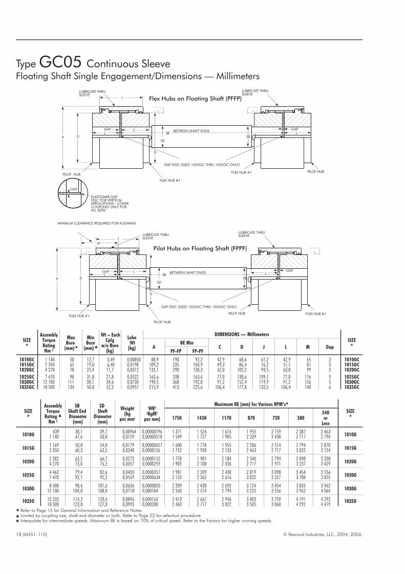
TypeGC05 Continuous SleeveFloating Shaft Single Engagement/Dimensions — Millimeters
SIZE�
AssemblyTorqueRatingNm †
MaxBore
(mm) �
MinBore
(mm) �
Wt – EachCplg
w/o Bore(kg)
LubeWt
(kg)
DIMENSIONS — MillimetersSIZE
�A
BE MinC D J L M Gap
PF-FP FP-PF
1010GC 1 140 50 12,7 3,49 0,00850 88,9 190 92,2 42,9 68,6 61,2 42,9 65 3 1010GC1015GC 2 350 65 19,0 6,40 0,0198 109,2 235 104,9 49,3 86,4 76,2 51,1 81 3 1015GC1020GC 4 270 78 25,4 11,7 0,0312 132,1 290 130,3 62,0 105,2 94,5 63,8 99 3 1020GC
1025GC 7 470 98 31,8 21,8 0,0522 163,6 338 163,6 77,0 130,6 109,1 77,0 116 5 1025GC1030GC 12 100 111 38,1 34,6 0,0730 190,5 368 192,0 91,2 152,4 119,9 91,2 126 5 1030GC1035GC 18 500 134 50,8 52,2 0,0957 215,9 413 225,6 106,4 177,8 133,5 106,4 140 6 1035GC
LGAP
A D
PILOT HUB
C
FLEX HUB #1
SD
J
LGAP
BETWEEN SHAFT ENDS
SB
LUBRICATE THRUSLEEVE
LUBRICATE THRUSLEEVE
FLEX HUB #1 PILOT HUB
D
BE
GAP DISC (SIZES 1025GC THRU 1035GC ONLY)
GAP
ELASTOMER GAPDISC FOR VERTICALAPPLICATIONS - LOWERCOUPLING ONLY FORALL SIZES
Pilot Hubs on Floating Shaft (FPPF)
Flex Hubs on Floating Shaft (PFFP)
LGAP
A D
PILOT HUB
C
FLEX HUB #1
SD
J
GAPBETWEEN SHAFT ENDS
SB
LUBRICATE THRUSLEEVELUBRICATE THRU
SLEEVE
FLEX HUB #1PILOT HUB
D
BE
GAP DISC (SIZES 1025GC THRU 1035GC ONLY)
M
MINIMUM CLEARANCE REQUIRED FOR ALIGNING
L
SIZE�
AssemblyTorque
Rating �
Nm †
SBShaft EndDiameter
(mm)
SDShaft
Diameter(mm)
Weight(kg
per mm)
WR2
(KgM2
per mm)
Maximum BE (mm) for Various RPM’s�
SIZE�
1750 1430 1170 870 720 580540or
Less
1010G439 38,1 39,7 0,00964 0,00000196 1 371 1 524 1 676 1 955 2 159 2 387 2 463
1010G1 140 47,6 50,8 0,0159 0,00000518 1 549 1 727 1 905 2 209 2 438 2 717 2 794
1015G1 169 50,8 54,0 0,0179 0,00000657 1 600 1 778 1 955 2 286 2 514 2 794 2 870
1015G2 350 60,3 63,5 0,0248 0,0000126 1 752 1 930 2 133 2 463 2 717 3 022 3 124
1020G2 282 63,5 66,7 0,0273 0,0000152 1 778 1 981 2 184 2 540 2 794 3 098 3 200
1020G4 270 73,0 76,2 0,0357 0,0000259 1 905 2 108 2 336 2 717 2 971 3 237 3 429
1025G4 463 79,4 82,6 0,0420 0,0000357 1 981 2 209 2 438 2 819 3 098 3 454 3 556
1020G7 470 92,1 95,2 0,0559 0,0000634 2 133 2 362 2 616 3 022 3 327 3 708 3 835
1030G8 508 98,4 101,6 0,0636 0,0000820 2 209 2 438 2 692 3 124 3 454 3 835 3 962
1030G12 100 104,8 108,0 0,0718 0,000104 2 260 2 514 2 794 3 225 3 556 3 962 4 064
1035G 13 333 114,3 120,6 0,0896 0,000163 2 413 2 667 2 946 3 403 3 759 4 191 4 292 1035G18 500 123,8 127,0 0,0993 0,000200 2 463 2 717 3 022 3 505 3 860 4 292 4 419
� Refer to Page 15 for General Information and Reference Notes.� Limited by coupling size, shaft end diameter or both. Refer to Page 22 for selection procedure.� Interpolate for intermediate speeds. Maximum BE is based on 70% of critical speed. Refer to the Factory for higher running speeds.
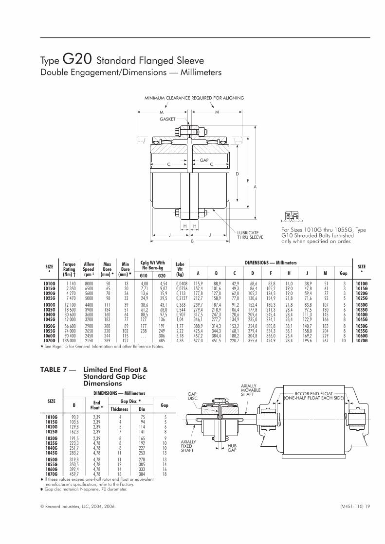
Type G20 Standard Flanged SleeveDouble Engagement/Dimensions — Millimeters
© Rexnord Industries, LLC, 2004, 2006. (M451-110) 19
C
D
F
A
MM
JJ
B
LUBRICATETHRU SLEEVE
MINIMUM CLEARANCE REQUIRED FOR ALIGNING
CGAP
H H
GASKET
SIZE�
TorqueRating(Nm) †
AllowSpeedrpm ‡
MaxBore
(mm) �
MinBore
(mm) �
Cplg Wt WithNo Bore-kg
LubeWt
(kg)
DIMENSIONS — MillimetersSIZE
�A B C D F H J M Gap
G10 G20
1010G 1 140 8000 50 13 4,08 4,54 0,0408 115,9 88,9 42,9 68,6 83,8 14,0 38,9 51 3 1010G1015G 2 350 6500 65 20 7,71 9,07 0,0726 152,4 101,6 49,3 86,4 105,2 19,0 47,8 61 3 1015G1020G 4 270 5600 78 26 13,6 15,9 0,113 177,8 127,0 62,0 105,2 126,5 19,0 59,4 77 3 1020G1025G 7 470 5000 98 32 24,9 29,5 0,2127 212,7 158,9 77,0 130,6 154,9 21,8 71,6 92 5 1025G
1030G 12 100 4400 111 39 38,6 43,1 0,363 239,7 187,4 91,2 152,4 180,3 21,8 83,8 107 5 1030G1035G 18 500 3900 134 51 61,2 68,0 0,544 279,4 218,9 106,4 177,8 211,3 28,4 97,5 130 6 1035G1040G 30 600 3600 160 64 88,5 97,5 0,907 317,5 247,3 120,6 209,6 245,4 28,4 111,3 145 6 1040G1045G 42 000 3200 183 77 127 136 1,04 346,1 277,7 134,9 235,0 274,1 28,4 122,9 166 8 1045G
1050G 56 600 2900 200 89 177 191 1,77 388,9 314,3 153,2 254,0 305,8 38,1 140,7 183 8 1050G1055G 74 000 2650 220 102 238 249 2,22 425,4 344,3 168,1 279,4 334,3 38,1 158,0 204 8 1055G1060G 90 400 2450 244 115 . . . 306 3,18 457,2 384,4 188,2 304,8 366,0 25,4 169,2 229 8 1060G1070G 135 000 2150 289 127 . . . 485 4,35 527,0 451,5 220,7 355,6 424,9 28,4 195,6 267 10 1070G
� See Page 15 for General Information and other Reference Notes.
TABLE 7 — Limited End Float &Standard Gap DiscDimensions
SIZE
DIMENSIONS — Millimeters
BEnd
Float �Gap Disc �
GapThickness Dia
1010G 90,9 2,39 4 75 51015G 103,6 2,39 4 94 51020G 129,8 2,39 5 114 61025G 162,3 2,39 7 141 8
1030G 191,5 2,39 8 165 91035G 223,3 4,78 8 192 101040G 251,7 4,78 8 227 101045G 283,2 4,78 11 253 13
1050G 319,8 4,78 11 278 131055G 350,5 4,78 12 305 141060G 392,4 4,78 14 333 161070G 459,7 4,78 16 384 18
� If these values exceed one-half rotor end float or equivalentmanufacturer’s specification, refer to the Factory.
� Gap disc material: Neoprene, 70 durometer.
For Sizes 1010G thru 1055G, TypeG10 Shrouded Bolts furnishedonly when specified on order.
ROTOR END FLOAT(ONE-HALF FLOAT EACH SIDE)
AXIALLYMOVABLESHAFT
HUBGAP
AXIALLYFIXEDSHAFT
GAPDISC

20 (M451-110) © Rexnord Industries, LLC, 2004, 2006.
SIZES�
TorqueRating(Nm) †
AllowSpeedrpm ‡
MaxBore
(mm) �
MinBore(mm)�
Coupling Wt-kg Lube Wt-kgDIMENSIONS — Millimeters
SIZE�
A
BE Min � BE Max
C D F H J MCplg WtWith No
Boreand
Min BE
ExtraSpacerWt permm ofLength
MinWt
LessSpacer
Plusper
mm ofSpacerLength
G31 G32G31 &G32
1010G 1 140 7000 50 13 6,80 0,0120 0,0408 . . . 115,9 82 82 311 42,9 68,6 83,8 14,0 38,9 48 1010G1015G 2 350 5500 65 20 13,6 0,0127 0,0726 . . . 152,4 82 82 311 49,3 86,4 105,2 19,0 47,8 56 1015G1020G 4 270 4600 78 26 20,4 0,0166 0,113 0,000536 177,8 82 82 311 62,0 105,2 126,5 19,0 59,4 69 1020G1025G 7 470 4000 98 32 38,6 0,0205 0,227 0,00107 212,7 108 95 311 77,0 130,6 154,9 21,8 71,6 81 1025G
1030G 12 100 3600 111 39 54,4 0,0236 0,363 0,00107 239,7 108 95 311 91,2 152,4 180,3 21,8 83.8 94 1030G1035G 18 500 3100 134 51 88,5 0,0359 0,544 0,00214 279,4 130 120 311 106,4 177,8 211,3 28,4 97,5 107 1035G1040G 30 600 2800 160 64 122,5 0,0500 0,907 0,00357 317,5 130 120 311 120,6 209,6 245,4 28,4 111,3 122 1040G1045G 42 000 2600 183 77 166 0,0736 1,04 0,00357 346,1 130 120 311 134,9 235,0 274,1 28,4 122,9 135 1045G
1050G 56 600 2400 200 89 238 0,0814 1,77 0,00357 388,9 184 146 311 153,2 254,0 305,8 38,1 140,7 152 1050G1055G 74 000 2200 220 102 306 0,0895 2,22 0,00357 425,4 184 146 311 168,1 279,4 334,3 38,1 158,0 173 1055G1060G 90 400 2100 244 115 358 0,117 3,18 0,00357 457,2 . . . 146 311 188,2 304,8 366,0 25,4 169,2 183 1060G1070G 135 000 1800 289 127 562 0,141 4,35 0,00357 527,0 . . . 146 311 220,7 355,6 424,9 28,4 195,6 208 1070G
� See Page 15 for General Information and other Reference Notes.� BE is the distance between shaft ends whether standard (stock) or special spacer lengths are used.
SIZEBE Spacers in Stock — mm
89 111 114 127 178
1010G � � . . . � . . .1015G � . . . . . . � . . .1020G . . . � . . . � �
1025G . . . . . . . . . � �
1030G . . . . . . . . . � �
1035G . . . . . . �� . . . . . .� Bolt holes staggered for assembly clearance.
Type G32 Standard Flanged SleeveSpacer/Dimensions — Millimeters
SIZE
DIMENSIONS — Millimeters
EndFloat �
SGAddition to Stock
BE Length �
1015G 2,4 0,5969 2,21020G 2,4 0,5969 2,71025G 2,4 0,5969 3,7
1030G 2,4 0,5969 4,71035G 4,8 1,19 4,71040G
thru1070G
4,8 1,19 None
� Refer to the Factory if these values exceed one-half the rotor end float or theequipment manufacturers’ specifications.
� Couplings with stock spacers and limited end float must add applicable addition tothe BE (Between Shaft Ends) dimension.
MINIMUMCLEARANCEREQUIREDFORALIGNING
D
C CBE
J
M
H H
FA
LUBRICATETHRUSLEEVES
GASKET
EXPOSEDBOLTS
SPACER
BETWEEN
SHAFTENDS
SPACERLIMITEDENDFLOATPLATES
BETWEEN
SHAFTENDS
BESG SG
BE
SG
EXPOSEDBOLTS
NON-STOCK SPACER DESIGNSIZES 1010 THRU 1070G32.
With Limited End Float(Refer to drawing at left for balance of dimensions.)
Without Limited End Float
Type G31 Shrouded Boltsfurnished only whenspecified on order.

© Rexnord Industries, LLC, 2004, 2006. (M451-110) 21
B
C
F
D
LCE
GAP
M
MINIMUM CLEARANCE REQUIRED FOR ALIGNING
F
A
RIGID HUB
QJ
H H
FLEX HUB
LUBRICATETHRU SLEEVE
B
GASKET
SIZE�
TorqueRating(Nm) †
AllowSpeedrpm ‡
Max Bore(mm) �
MinBore(mm)�
Cplg Wt WithNo Bore-kg Lube
Wt(kg)
DIMENSIONS — Millimeters
SIZE�
A B C D E F H J L M Q GapFlexHub
RigidHub
G51 G52
1010G 1 140 8000 50 65 13 4,08 4,54 0,0227 115,9 86,6 42,9 68,6 2,5 83,8 14,0 38,9 39,6 51 42,2 4 1010G1015G 2 350 6500 65 80 20 8,16 9,07 0,0408 152,4 99,6 49,3 86,4 2,5 105,2 19,0 47,8 46,2 61 48,8 4 1015G1020G 4 270 5600 78 98 26 13,6 15,9 0,0680 177,8 124,5 62,0 105,2 2,5 126,5 19,0 59,4 58,4 76 61,0 4 1020G1025G 7 470 5000 98 118 32 24,9 27,2 0,118 212,7 155,4 77,0 130,6 2,5 154,9 21,8 71,6 73,7 91 76,2 5 1025G
1030G 12 100 4400 111 140 39 38,6 43,1 0,181 239,7 183,9 91,2 152,4 2,5 180,3 21,8 83,8 87,9 107 90,4 5 1030G1035G 18 500 3900 134 163 51 61,2 68,0 0,272 279,4 214,1 106,4 177,8 2,5 211,3 28,4 97,5 102,1 130 104,6 6 1035G1040G 30 600 3600 160 196 64 90,7 99,8 0,467 317,5 242,8 120,6 209,6 4,1 245,4 28,4 111,3 115,3 145 119,4 7 1040G1045G 42 000 3200 183 216 77 129,3 136 0,557 346,1 273,1 134,9 235,0 4,1 274,1 28,4 122,9 130,6 165 134,6 8 1045G
1050G 56 600 2900 200 235 89 181,4 195 0,907 388,9 309,1 153,2 254,0 5,1 305,8 38,1 140,7 147,3 183 152,4 9 1050G1055G 74 000 2650 220 266 102 251,7 263 1,13 425,4 349,5 168,1 279,4 5,1 334,3 38,1 158,0 172,7 203 177,8 9 1055G1060G 90 400 2450 244 290 115 . . . 324 1,70 457,2 385,1 188,2 304,8 6,6 366,0 25,4 169,2 186,4 229 193,0 10 1060G1070G 135 000 2150 289 340 127 . . . 508 2,27 527,0 453,6 220,7 355,6 8,4 424,9 28,4 195,6 220,2 267 228,6 13 1070G
� See Page 15 for General Information and other Reference Notes.
Type G52 Standard Flanged SleeveSingle Engagement/Dimensions — Millimeters
For Sizes 1010G thru 1055G, TypeG51 Shrouded Bolts furnishedonly when specified on order.

Type G52 Standard Flanged SleeveFloating Shafts/Dimensions — Millimeters
22 (M451-110) © Rexnord Industries, LLC, 2004, 2006.
SIZE�
AssemblyTorque
Rating �
Nm †
Floating Shafts — Millimeters
SBShaft EndDiameter
(mm)
SDShaft
Diameter(mm)
Wt-kgpermm
WR2
kgm2
per mm
Maximum BE (mm) for Various RPM’s �
1750 1430 1170 870 720 580540or
less
1010G493 38,1 39,7 0,00964 0,00000196 1 371 1 524 1 676 1 955 2 159 2 387 2 463
1 140 47,6 50,8 0,0159 0,00000518 1 549 1 727 1 905 2 209 2 438 2 717 2 794
1015G1 169 50,8 54,0 0,0179 0,00000657 1 600 1 778 1 955 2 286 2 514 2 794 2 8702 349 60,3 76,2 0,0248 0,0000126 1 752 1 930 2 133 2 463 2 717 3 022 3 124
1020G2 282 63,5 66,7 0,0273 0,0000152 1 778 1 981 2 184 2 540 2 794 3 098 3 2004 271 73,0 95,2 0,0557 0,0000259 1 905 2 108 2 336 2 717 2 971 3 327 3 429
1025G4 463 79,4 82,6 0,0420 0,0000357 1 981 2 209 2 438 2 819 3 098 3 454 3 5567 474 92,1 95,2 0,0559 0,0000634 2 133 2 362 2 616 3 022 3 237 3 708 3 835
1030G8 508 98,4 101,6 0,0636 0,0000820 2 209 2 438 2 692 3 124 3 454 3 835 3 962
12 101 104,8 127,0 0,0718 0,000104 2 260 2 514 2 794 3 225 3 556 3 962 4 064
1035G13 333 114,3 120,6 0,0896 0,000163 2 413 2 667 2 946 3 403 3 759 4 191 4 29218 508 123,8 146,0 0,993 0,000200 2 463 2 717 3 022 3 505 3 860 4 292 4 419
1040G24 327 139,7 146,0 0,131 0,000350 2 641 2 921 3 251 3 759 4 140 4 597 4 74930 609 146,0 165,1 0,143 0,000415 2 692 2 997 3 302 3 835 4 216 4 699 4 851
1045G31 581 152,4 165,1 0,168 0,000572 2 819 3 124 3 454 3 987 4 394 4 902 5 02941 999 171,5 203,2 0,254 0,00131 3 124 3 454 3 810 4 445 4 876 5 435 5 588
1050G37 886 161,9 165,1 0,168 0,000572 2 819 3 124 3 454 3 987 4 394 4 902 5 02956 597 187,3 203,2 0,254 0,00131 3 124 3 454 3 810 4 445 4 876 5 435 5 588
1055G37 886 161,9 165,1 0,168 0,000572 2 819 3 124 3 454 3 987 4 394 4 902 5 02974 031 200,0 203,2 0,254 0,00131 3 124 3 454 3 810 4 445 4 876 5 435 5 588
1060G71 410 200,0 203,2 0,254 0,00131 3 124 3 454 3 810 4 445 4 876 5 435 5 58890 404 215,9 217,4 0,291 0,00172 3 225 3 581 3 962 4 597 5 054 5 613 5 791
1070G71 410 200,0 203,2 0,254 0,00131 3 124 3 454 3 810 4 445 4 876 5 435 5 588
135 250 241,3 242,8 0,363 0,00268 3 403 3 784 4 191 4 851 5 334 5 943 6 121
� Refer to Page 15 for General Information and Reference Notes.� Assembly torque rating is limited by coupling size, shaft end diameter or both.� Interpolate for intermediate speeds. Maximum BE is based on 70% of critical speed. Refer to the Factory for higher running speeds.
A standard floating shaft assembly consists of two standard singleengagement couplings, two gap discs and a connecting shaft.
A floating shaft can eliminate the need for additional bearingsupports along spanning shaft because the shaft is supported atthe ends by connected equipment through the single engagementcouplings.
Flex Hubs on Floating Shaft (RFFR)
Assembly of the flex hubs on the floating shaft allows for easierreplacement in case of wear and allows the rigid hubs with theirincreased bore capacity to be used on the connected equipmentshafts. This frequently means a smaller coupling size can beutilized.
Rigid Hubs on Floating Shaft (FRRF)
When the rigid hubs are on the floating shaft, shorter shaft spanscan be accommodated, since no cover drawback is required.Since the flex hubs are outboard, the points of articulation arefurther apart, providing greater offset misalignment capacity.
Solid Floating Shaft Selection
Single Engagement Type G52/GV52 couplings are used withfloating shafts in either horizontal or vertical applications. Forvertical applications select a Type GV coupling for the lowercoupling assembly. Select floating shafts as follows:
1. Use the Standard or Formula Selection Methods, Pages 10-11 toselect the couplings. Record the System Torque from standardselection method or Selection Torque from formula selection method.
2. From table below select a shaft diameter that has an assemblytorque rating equal to or greater than the system or selectiontorque determined in coupling selection.
3. Check maximum “BE” for the shaft diameter selected andrunning speed for shaft length required from table below. Referto graph at left to determine if shaft requires balancing.
4. If the application shaft length exceeds the maximum “BE” listed,select the next larger shaft diameter or the next larger sizecoupling. Consult the Factory for higher speeds or longer shaftlengths than listed below.
NOTE: For conditions that require a larger size coupling,consider a Tubular Shaft Design, refer complete applicationdetails to your local Rexnord Representative.
2000
1500
1000
500
254 508 762 1016 1270 1524 1778 2032
DISTANCE BETWEEN SHAFT ENDS – MILLIMETERS
OPERATINGSPEED–RPM
BALANCINGNORMALLY NOTREQUIRED
BALANCING OFSHAFT REQUIRED

© Rexnord Industries, LLC, 2004, 2006. (M451-110) 23
SIZE�
Max Bore(mm) �
MinBore(mm)�
Wt–One CplgNo Bore–kg
LubeWtPerCplg(kg)
DIMENSIONS — Millimeters
A
BE Min
C D E F H J L M Q GapFlexHub
RigidHub
G51 G52 RFFR FRRF
1010G 50 65 13 4,08 4,54 0,0227 115,9 133 92 42,9 68,6 2,5 83,8 14,0 38,9 39,6 48 42,2 41015G 65 80 20 8,16 9,07 0,0408 152,4 159 105 49,3 86,4 2,5 105,2 19,0 47,8 46,2 56 48,8 41020G 78 98 26 13,6 15,9 0,0680 177,8 197 129 62,0 105,2 2,5 126,5 19,0 59,4 58,4 69 61,0 41025G 98 118 32 24,9 27,2 0,118 212,7 241 162 77,0 130,6 2,5 154,9 21,8 71,6 73,7 81 76,2 5
1030G 111 140 39 38,6 43,1 0,181 239,7 279 189 91,2 152,4 2,5 108,3 21,8 83,8 87,9 94 90,4 51035G 134 163 51 61,2 68,0 0,272 279,4 324 219 106,4 177,8 2,5 211,3 28,4 97,5 102,1 107 104,6 61040G 160 196 64 90,7 99,8 0,467 317,5 419 248 120,6 209,6 4,1 245,4 28,4 111,3 115,3 122 119,4 71045G 183 216 77 129,3 136 0,557 346,1 508 281 134,9 235,0 4,1 274,1 28,4 122,9 130,8 135 134,6 8
1050G 200 235 89 181,4 195 0,907 388,9 533 316 153,2 254,0 5,1 305,8 38,1 140,7 147,3 152 152,4 91055G 220 266 102 251,7 263 1,13 425,4 572 367 168,1 279,4 5,1 334,3 38,1 158,0 172,7 173 177,8 91060G 244 290 115 . . . 324 1,70 457,2 597 397 188,2 304,8 6,6 366,0 25,4 169,2 186,4 183 193,0 101070G 289 340 127 . . . 508 2,27 527,0 673 470 220,7 355,6 8,4 424,9 28,4 195,6 220,2 208 228,6 13
� Refer to Page 15 for General Information and Reference Notes.
Type G52 Standard Flanged SleeveFloating Shaft/Dimensions — Millimeters
GAP GAP
C FD
SD
SB
A
F LBEBETWEENSHAFT ENDSL
FLEXHUB RIGIDHUBFLEXHUB
GAPDISC GAPDISC
RIGIDHUB
E
JQ LUBRICATETHRUSLEEVES
H H
GASKET
GASKET
GAP
SD
C
M
FLEXHUBRIGIDHUB
MINIMUMCLEARANCEREQUIREDFORALIGNING
RIGIDHUB
SBBETWEENSHAFT ENDS
GAPDISC
A
F
FL
GAP
H H
D C
FLEXHUB
GAPDISC
E
QJ
LUBRICATETHRUSLEEVES
GASKET
GASKET
BE
Flex Hubs on Floating Shaft (RFFR)
Rigid Hubs on Floating Shaft (FRRF)
For Sizes 1010G thru 1055G, TypeG51 Shrouded Bolts furnishedonly when specified on order.
24 (M451-110) © Rexnord Industries, LLC, 2004, 2006.
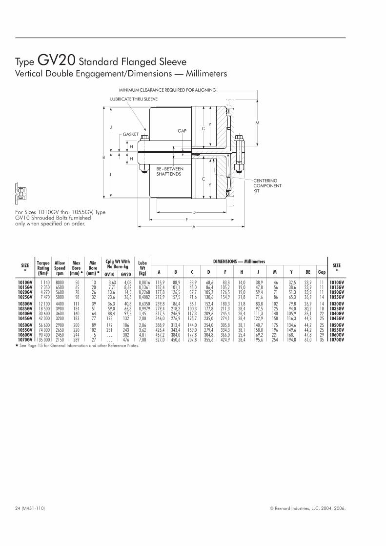
Type GV20 Standard Flanged SleeveVertical Double Engagement/Dimensions — Millimeters
Y M
C
Y
A
J
J
B H
H
GASKETGAP
BE - BETWEENSHAFTENDS
F
D
C CENTERINGCOMPONENTKIT
MINIMUMCLEARANCEREQUIREDFORALIGNING
LUBRICATE THRUSLEEVE
SIZE�
TorqueRating(Nm)†
AllowSpeedrpm
MaxBore
(mm) �
MinBore
(mm) �
Cplg Wt WithNo Bore-kg
LubeWt
(kg)
DIMENSIONS — MillimetersSIZE
�A B C D F H J M Y BE Gap
GV10 GV20
1010GV 1 140 8000 50 13 3,63 4,08 0,0816 115,9 88,9 38,9 68,6 83,8 14,0 38,9 46 32,5 23,9 11 1010GV1015GV 2 350 6500 65 20 7,71 8,62 0,1361 152,4 101,1 45,0 86,4 105,2 19,0 47,8 56 38,6 23,9 11 1015GV1020GV 4 270 5600 78 26 13,6 14,5 0,2268 177,8 126,5 57,7 105,2 126,5 19,0 59,4 71 51,3 23,9 11 1020GV1025GV 7 470 5000 98 32 23,6 26,3 0,4082 212,9 157,5 71,6 130,6 154,9 21,8 71,6 86 65,3 26,9 14 1025GV
1030GV 12 100 4400 111 39 36,3 40,8 0,6350 239,8 186,4 86,1 152,4 180,3 21,8 83,8 102 79,8 26,9 14 1030GV1035GV 18 500 3900 134 51 59,0 65,8 0,9979 279,4 218,2 100,3 177,8 211,3 28,4 97,5 125 94,0 30,2 18 1035GV1040GV 30 600 3600 160 64 88,4 97,5 1,45 317,5 246,9 112,3 209,6 245,4 28,4 111,3 140 105,9 35,1 22 1040GV1045GV 42 000 3200 183 77 123 132 2,00 346,0 276,9 125,7 235,0 274,1 28,4 122,9 158 116,3 44,2 25 1045GV
1050GV 56 600 2900 200 89 172 186 2,86 388,9 313,4 144,0 254,0 305,8 38,1 140,7 175 134,6 44,2 25 1050GV1055GV 74 000 2650 220 102 231 243 3,62 425,4 343,4 159,0 279,4 334,3 38,1 158,0 196 149,6 44,2 25 1055GV1060GV 90 400 2450 244 115 . . . 302 4,81 457,2 384,0 177,8 304,8 366,0 25,4 169,2 221 168,1 47,8 29 1060GV1070GV 135 000 2150 289 127 . . . 476 7,08 527,0 450,6 207,8 355,6 424,9 28,4 195,6 254 194,8 61,0 35 1070GV
� See Page 15 for General Information and other Reference Notes.
For Sizes 1010GV thru 1055GV, TypeGV10 Shrouded Bolts furnishedonly when specified on order.

© Rexnord Industries, LLC, 2004, 2006. (M451-110) 25
SIZE�
TorqueRating(Nm)�†
AllowSpeedrpm ‡
Max Bore(mm) � Min
Bore(mm) �
Cplg Wt WithNo Bore-kg Lube
Wt(kg)
DIMENSIONS — Millimeters
SIZE�
A B C D F H J L M R Y BE GapFlexHub
RigidHub
GV51 GV52
1010GV 1 140 7000 50 65 13 4,08 4,54 0,0363 115,9 86,9 38,9 68,6 83,8 14,0 38,9 39,6 45,7 131,6 32,5 14,7 4 1010GV1015GV 2 350 5500 65 80 20 8,16 9,07 0,0544 152,4 99,6 45,0 86,4 105,2 19,0 47,8 46,2 55,9 152,4 38,6 14,7 4 1015GV1020GV 4 270 4600 78 98 26 14,5 15,9 0,0907 177,8 124,5 57,7 105,2 126,5 19,0 59,4 58,4 71,1 182,9 51,3 14,7 4 1020GV1025GV 7 470 4000 98 118 32 24,9 27,2 0,1814 212,7 155,2 71,6 130,6 154,9 21,8 71,6 73,7 86,4 217,7 65,3 16,3 5 1025GV
1030GV 12 100 3600 111 140 39 38,6 43,1 0,2722 239,7 183,9 86,1 152,4 180,3 21,8 83,8 87,9 101,6 247,7 79,8 16,3 5 1030GV1035GV 18 500 3100 134 163 51 61,2 68,0 0,4536 279,4 214,1 100,3 177,8 211,3 28,4 97,5 102,1 124,5 297,9 94,0 18,0 7 1035GV1040GV 30 600 2800 160 196 64 93,0 102 0,6804 317,5 243,3 112,3 209,6 245,4 28,4 111,3 115,3 139,7 340,4 105,9 22,0 8 1040GV1045GV 42 000 2600 183 216 77 129 138 0,9072 346,1 273,6 125,7 235,0 274,1 28,4 122,9 130,6 157,5 388,1 116,3 26,7 9 1045GV
1050GV 56 600 2400 200 235 89 184 197 1,36 388,9 309,6 144,0 254,0 305,8 38,1 140,7 147,3 175,3 423,7 134,6 27,7 8 1050GV1055GV 74 000 2200 220 266 102 254 265 1,68 425,4 350,0 159,0 279,4 334,3 38,1 158,0 172,7 195,6 464,3 149,6 27,7 8 1055GV1060GV 90 400 2100 244 290 115 . . . 390 2,27 457,2 385,6 177,8 304,8 366,0 25,4 169,2 186,4 221,0 522,2 168,1 30,9 8 1060GV1070GV 135 000 1800 289 340 127 . . . 517 3,27 527,0 454,2 207,8 355,6 424,9 28,4 195,6 220,2 254,0 615,2 194,8 39,1 10 1070GV
� See Page 15 for General Information and other Reference Notes.� Torque Rating is for coupling only; refer to Page 22 for floating shaft selection and ratings.� Allowable speed listed is for GV52 coupling only; refer to Page 22 for floating shaft selection and running speed.
Y M
C
L
J
B
H
H
GASKET
GAP
BE - BETWEENSHAFTENDS
A
F
D
CENTERINGCOMPONENTKIT
MINIMUMCLEARANCEREQUIREDFORALIGNING
LUBRICATETHRUSLEEVE
FLEXHUB
RIGID HUB
For Sizes 1010GV thru 1055GV, TypeGV51 Shrouded Bolts furnishedonly when specified on order.
RMinimumDistanceBetweenShafts
Use G52at Top
Use GV52at Bottom
FloatingShaftDesign
Type GV52 Standard Flanged SleeveVertical Single Engagement/Dimensions — Millimeters
Downward load capacity of lower support button
Sizes 1010 thru1030GV52 is 4 536 kg
Sizes 1035 thru 1070GV52 is 13 608 kg

26 (M451-110) © Rexnord Industries, LLC, 2004, 2006.
BrakewheelSize �
CPLGSIZE
�
BrakeRating
ofCoup-ling(Nm)
MaxStraight
Bore (mm) �MinBore(mm)�
Cplg Wt With NoBore-kg Less
Wheel
Lube Wt(kg)
DIMENSIONS — Millimeters
A
B
C D E F H J L M Q W
Gap
Dia.(Min)
AB(mm)
FlexHub
RigidHub
G62G63
G66G62G63
G66G62G63
G66WithStd
LengthHubs
G62G63
G66
177,8 1010G 251 50 65 13 4,54 4,54 0,0454 0,0272 115,9 98,6 96,3 42,9 68,6 2,5 83,8 14,0 38,9 39,6 51 42,2 9,7 13 14203,2 1010G 569 65 80 10 9,07 9,07 0,0907 0,0544 152,4 114,3 112,3 49,3 86,4 2,5 105,2 19,0 47,8 46,2 61 48,8 12,7 16 17244,3 1020G 1 050 78 98 26 15,9 15,9 0,1361 0,0907 177,8 139,7 137,2 62,0 105,2 2,5 126,5 19,0 59,4 58,4 76 61,0 12,7 16 17289 1025G 1 897 98 118 32 29,5 27,2 0,2722 0,1588 212,7 173,0 169,7 77,0 130,6 2,5 154,9 21,8 71,6 73,7 91 76,2 14,2 19 19
320,5 1030G 3 117 111 140 39 43,1 43,1 0,4082 0,2268 239,7 201,4 198,1 91,2 152,4 2,5 180,3 21,8 83,8 87,9 107 90,4 14,2 19 19371,3 1035G 4 810 134 163 51 68,0 68,0 0,5670 0,3402 279,4 238,3 233,2 106,4 177,8 2,5 211,3 28,4 97,5 102,1 130 104,6 19,0 25 25428,7 1040G 7 317 160 196 64 97,5 99,8 0,9072 0,5443 317,5 266,7 261,9 120,6 209,6 4,1 245,4 28,4 111,3 115,3 145 119,4 19,0 25 26457,2 1045G 10 027 183 216 77 136 136 1,1340 0,6350 346,1 296,7 292,1 134,9 235,0 4,1 274,1 28,4 122,9 130,6 165 134,6 19,0 27 27
492,2 1050G 13 550 200 235 89 191 195 1,8688 1,1340 388,9 339,6 334,5 153,2 254,0 5,1 305,8 38,1 140,7 147,3 183 152,4 25,4 33 34530,3 1055G 17 784 220 266 102 249 263 2,3224 1,3608 425,4 369,8 374,9 168,1 279,4 5,1 334,3 38,1 158,0 172,7 203 177,8 25,4 33 34584,2 1060G 23 035 244 290 115 306 324 3,4019 1,9278 457,2 409,4 410,5 188,2 304,8 6,6 366,0 25,4 169,2 186,4 229 193,0 25,4 33 36660,4 1070G 33 469 289 340 127 485 508 4,4452 2,6082 527,0 476,3 479,0 220,7 355,6 8,4 424,9 28,4 195,6 220,2 267 228,6 25,4 35 38
� See Page 15 for General Information and other Reference Notes.� Maximum rim velocity is 182,88 meters per minute. Brakewheel must be balanced if peripheral speed exceeds 182,88 meters per minute.� Dimensions and allowable speed vary with application; consult the Factory.� Dimensions AC and JC depend upon customer caliper specifications.
MD
AB
JB
NC
M
A
J
B
FD
C C
W
HH
GAP
MC
NB
LUBRICATETHRUSLEEVE
BRAKE CL
MD
AB
JB
NC
A
QJ
B
FFD
C L
W
HH
GAP
MC
NB
BRAKE CL
MINIMUMCLEARANCEREQUIREDFORALIGNING
RIGIDHUB
FLEXHUB
E
AC
M
A
J
B
FD
C C
W
HH
GAP
MC
NB
LUBRICATETHRUSLEEVE
DISC CL
MINIMUMCLEARANCEREQUIREDFORALIGNING
JC
Double Engagement Type G62 Single Engagement Type G66
Straight Bores — Wheel Sizes 177,8 Millimeters Diameter & Larger
Double Engagement Type G63 �
Types G62, G63 & G66 Standard Flanged SleeveBrakewheel/Disc Brake/Dimensions — Millimeters

© Rexnord Industries, LLC, 2004, 2006. (M451-110) 27
BrakewheelDia x Face � Wheel
Draw-ingNo.
CPLGSIZE
�
MillMotorSize
AllowSpeedrpm
�
BrakeRating(Nm)�
Brake Manufacturer& Catalog Number
DIMENSIONS — Millimeters
C L MMAMBMax
MCMDMax
NB
NC ZD ZE
Gap
Dimensions(mm)
AB x JB
C-HCo.
E.C. &M.
G.E. WestFig
1 & 3Fig2
Fig1
Fig2 & 3
203,2 x 82,6 330155 1015G 802 2860 136 8 T-08 A100 TM83 49,3 46,2 61,0 114,3 73,7 14,2 15,5 37,3 23,9 76,2 16 17254,0 x 95,3 330156 1015G 803,804 2290 271 10 T-10 A101 TM1035 49,3 46,2 61,0 127,0 73,7 22,4 23,4 51,6 25,4 88,9 16 17330,2 x 146,1 330158 1020G 806 1760 745 13 T-13 A102 TM1355 62,0 58,4 76,2 142,7 88,9 19,1 20,3 73,9 28,7 101,6 16 17330,2 x 146,1 330159 1025G 808 1760 745 13 T-13 A102 TM1355 77,0 73,7 91,4 158,8 104,1 28,4 29,0 81,0 31,8 114,3 19 19
406,4 x 171,5 330160 1025G 810 1430 1 355 16 T-16 A103 TM1665 77,0 73,7 91,4 162,1 119,9 3,0 � 3,6 68,3 35,1 114,3 19 19482,6 x 222,3 330162 1030G 812 1200 2 710 19 T-19 A104 TM1985 91,2 87,9 106,7 177,8 149,4 6,4 � 5,8 84,1 38,1 127,0 19 19482,6 x 222,3 330163 1035G 816 1200 2 710 19 T-19 A104 TM1985 106,4 102,1 129,5 180,3 167,1 3,0 3,0 88,1 41,4 127,0 25 25584,2 x 285,8 330164 1040G 818 995 5 420 23 T-23 A105 TM2311 120,6 115,3 144,8 208,3 198,6 0 12,7 116,6 44,5 139,7 25 27
584,2 x 285,8 330165 1040G 820 995 5 420 23 T-23 A105 TM2311 120,6 115,6 144,8 211,1 209,8 11,2 � 9,9 � 105,7 33,3 152,4 25 27762 x 362 330166 1050G 822 765 12 195 30 . . . . . . . 153,2 147,3 182,9 215,9 270,0 11,2 9,4 � 136,7 44,5 171,5 33 35762 x 362 330167 1050G 824 765 12 195 30 . . . . . . . 153,2 147,3 182,9 244,3 247,9 4,8 6,4 152,4 60,2 184,2 33 35
� See Page 15 for General Information and other Reference Notes.� For standard AISE brakes.� Based on maximum rim velocity of 182,88 meters per minute.� Symbol indicates that Dimension NB and the brakewheel centerline are to the left of the hub face.
Types G62/G66 Standard Flanged SleeveBrakewheel (for AISE Brakes)/Dimensions —Millimeters
BRAKE BASELINE
CLFLEXHUB FLEXHUB
AB
ZE
JB
MA
MB
ZD
NB
NC
C
M
GAP
MAX.
BORE
MINIMUM CLEARANCE REQUIREDFOR ALIGNING.
BRAKE BASELINE
CL
RIGIDHUB FLEXHUB
AB
ZE
MOTOR END
JB
MA
MB
ZD
NB
NC
L
MINIMUMCLEARANCEREQUIRED
GAP
MAX.
BORE
FOR ALIGNING.
BRAKEBASELINE
CLFLEXHUB RIGIDHUB
AB
ZE
MOTOR END
JB
MC
MD
ZD
NB
NC
C
MINIMUMCLEARANCEREQUIRED
GAP
MAX.
BORE
FOR ALIGNING.
Double Engagement Type G62(One Hub Taper Bored)
Figure 1
Single Engagement Type G66(Flex Hub Taper Bored)
Figure 2
Single Engagement Type G66(Rigid Hub Taper and C’ Bored)
Figure 3
Taper Bores — Wheel Sizes 203,2 Millimeters – 762 Millimeters Diameter & Larger
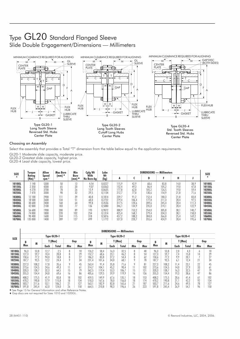
28 (M451-110) © Rexnord Industries, LLC, 2004, 2006.
SIZE
DIMENSIONS — Millimeters
Type GL20-1 Type GL20-2 Type GL20-4
BMax
MT (Max) Gap B
MaxM
T (Max) Gap BMax
MT (Max) Gap
Each Total Min Max Each Total Min Max Each Total Min Max
1010GL 96,3 53,8 12,7 2,5 8 10 126,2 58,4 16,3 32,5 8 40 96,3 53,8 2,0 4,3 6 101015GL 127,3 59,7 10,4 20,8 8 29 152,7 68,6 23,1 46,2 8 54 127,3 59,7 7,4 15,0 14 291020GL 150,6 77,2 94,0 18,8 8 27 186,2 83,8 27,2 54,4 8 62 150,6 77,2 9,9 20,1 7 271025GL 187,7 93,5 12,2 24,4 9 34 231,4 101,6 34,0 68,1 9 78 187,7 93,5 6,1 12,4 21 34
1030GL 227,3 108,2 17,8 35,6 9 45 263,4 91,4 35,8 71,6 9 81 227,3 108,2 11,4 23,1 22 451035GL 273,6 124,5 24,6 49,3 11 61 314,7 104,1 45,2 90,4 11 102 273,6 124,5 14,0 27,9 33 611040GL 320,3 138,7 32,3 64,5 15 79 362,5 119,4 53,3 106,7 15 121 320,3 138,7 16,3 32,5 47 791045GL 355,3 154,4 34,8 69,6 16 86 405,6 129,5 59,9 119,9 16 136 355,3 154,4 19,3 38,6 47 86
1050GL 408,2 175,5 41,9 83,8 18 102 459,5 149,9 67,6 135,1 18 153 408,2 175,5 20,6 41,4 61 1021055GL 470,2 190,8 57,9 115,8 18 134 510,3 167,6 78,0 156,0 18 174 470,2 190,8 21,1 42,2 92 1341060GL 503,7 211,6 53,1 106,2 21 127 563,1 182,9 82,8 165,6 21 187 503,7 211,6 24,6 49,5 78 1271070GL 591,8 245,4 62,0 124,0 26 150 664,5 210,8 98,3 196,6 26 223 591,8 245,4 26,9 54,1 96 150
� See Page 15 for General Information and other Reference Notes.� Gap discs are not required for Sizes 1010 and 1020GL.
SIZE�
TorqueRating(Nm) †
AllowSpeedrpm ‡
Max Bore(mm) �
MinBore
(mm) �
Cplg WtWith
No Bore-kg
LubeWt
(kg)
DIMENSIONS — MillimetersSIZE
�A C D F H J
1010GL 1 140 5300 50 13 4,54 0,0227 115,9 42,9 68,6 83,8 14,0 38,9 1010GL1015GL 2 350 4300 65 20 9,07 0,0363 152,4 49,3 86,4 105,2 19,0 47,8 1015GL1020GL 4 270 3700 78 26 15,9 0,0635 177,8 62,0 105,2 126,5 19,0 59,4 1020GL1025GL 7 470 3300 98 32 29,5 0,1134 212,7 77,0 130,6 154,9 21,8 71,6 1025GL
1030GL 12 100 2900 111 39 40,8 0,1814 239,7 91,2 152,4 180,3 21,8 83,8 1030GL1035GL 18 500 2600 134 51 68,0 0,2722 279,4 106,4 177,8 211,3 28,4 97,5 1035GL1040GL 30 600 2400 160 64 99,8 0,4536 317,5 120,6 209,6 245,4 28,4 111,3 1040GL1045GL 42 000 2100 183 77 136 0,5080 346,1 134,9 235,0 274,1 28,4 122,9 1045GL
1050GL 56 600 1900 200 89 193 0,9072 388,9 153,2 254,0 305,8 38,1 140,7 1050GL1055GL 74 000 1800 220 102 254 0,1314 425,4 168,1 279,4 334,3 38,1 158,0 1055GL1060GL 90 400 1600 244 115 318 0,5876 457,2 188,2 304,8 366,0 25,4 169,2 1060GL1070GL 135 000 1400 289 127 499 1,1772 527,0 220,7 355,6 424,9 28,4 195,6 1070GL
GASKETB
J J
H
AGAP F
D
H
TCC
M M
T
CENTERPLATE
FLEXHUB
FLEXHUB
LUBRICATETHRUSLEEVE
GLSLEEVE
MINIMUMCLEARANCEREQUIREDFORALIGNING
GASKETB
J J
H
AGAP F
D
H
TCC
M M
T
CENTERPLATE
FLEXHUB
FLEXHUB
LUBRICATETHRUSLEEVE
GLSLEEVE
MINIMUMCLEARANCEREQUIREDFORALIGNING
GASKETB
J J
H
AGAP F
D
H
TCC
M M
T
CENTERPLATE
FLEXHUB
FLEXHUB
LUBRICATETHRUSLEEVE
GAPDISC(BOTHSIDES)
MINIMUMCLEARANCEREQUIREDFORALIGNING
Type GL20-1Long Tooth SleeveReversed Std. Hubs
Center Plate
Type GL20-2Long Tooth SleevesCutoff Long Hubs
Center Plate
Type GL20-4Std. Tooth SleevesReversed Std. Hubs
Center Plate
Choosing an Assembly
Select the assembly that provides a Total “T” dimension from the table below equal to the application requirements.
GL20-1 Moderate slide capacity, moderate price.GL20-2 Greatest slide capacity, highest price.GL20-4 Least slide capacity, lowest price.
Type GL20 Standard Flanged SleeveSlide Double Engagement/Dimensions — Millimeters
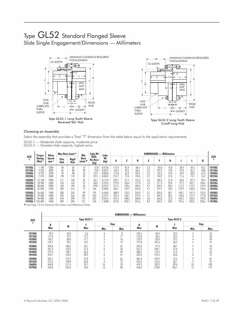
© Rexnord Industries, LLC, 2004, 2006. (M451-110) 29
SIZE�
DIMENSIONS — Millimeters
Type GL52-1 Type GL52-2
BMax
MT
Max
Gap BMax
MT
Max
Gap
Min Max Min Max
1010GL 90,2 53,8 3,6 4 8 105,2 58,4 18,5 4 231015GL 112,3 59,7 12,7 4 17 125,0 68,6 25,4 4 301020GL 136,1 84,8 11,7 4 16 153,9 83,8 29,5 4 341025GL 169,7 93,5 14,5 5 19 191,8 101,6 36,3 5 41
1030GL 204,0 108,2 20,1 5 25 222,0 91,4 38,1 5 431035GL 241,3 124,5 27,2 6 33 261,9 104,1 47,8 6 531040GL 279,4 138,7 36,3 7 43 300,5 119,4 57,4 7 651045GL 314,7 154,4 38,9 8 47 337,8 129,5 64,0 8 72
1050GL 356,1 175,5 47,0 9 56 381,8 149,9 72,6 9 811055GL 412,5 190,8 63,0 9 72 432,6 167,6 83,1 9 921060GL 444,8 211,6 59,7 10 70 474,5 182,9 89,4 10 1001070GL 524,0 245,4 70,4 13 83 560,3 210,8 106,7 13 119
SIZE�
TorqueRating(Nm) †
AllowSpeedrpm ‡
Max Bore (mm) �MinBore
(mm) �
Cplg WtWith
No Bore(kg)
LubeWt
(kg)
DIMENSIONS — MillimetersSIZE
�A C D E F H J L Q
FlexHub
RigidHub
1010GL 1 140 5300 50 65 13 4,54 0,0136 115,9 42,9 68,6 2,5 83,8 14,0 38,9 39,6 42,2 1010GL1015GL 2 350 4300 65 80 20 9,07 0,0227 152,4 49,3 86,4 2,5 105,2 19,0 47,8 46,2 48,8 1015GL1020GL 4 270 3700 78 98 26 15,9 0,0363 177,8 62,0 105,2 2,5 126,5 19,0 59,4 58,4 61,0 1020GL1025GL 7 470 3300 98 118 32 29,5 0,0635 212,7 77,0 130.6 2,5 154,9 21,8 71,6 73,7 76,2 1025GL
1030GL 12 100 2900 111 140 39 43,1 0,1134 239,7 91,2 152,4 2,5 180,3 21,8 83,8 87,9 90,4 1030GL1035GL 18 500 2600 134 163 51 68,0 0,1814 279,4 106,4 177,8 2,5 211,3 28,4 97,5 102,1 104,6 1035GL1040GL 30 600 2400 160 196 64 99,8 0,2722 317,5 120,6 209,6 4,1 245,4 28,4 111,3 115,3 119,4 1040GL1045GL 42 000 2100 183 216 77 136 0,3402 346,1 134,9 235,0 4,1 274,1 28,4 122,9 130,6 134,6 1045GL
1050GL 56 600 1900 200 235 89 195 0,5443 388,9 153,2 254,0 5,1 305,8 38,1 140,7 147,3 152,4 1050GL1055GL 74 000 1800 220 266 102 263 0,7257 425,4 168,1 279,4 5,1 334,3 38,1 158,0 172,7 177,8 1055GL1060GL 90 400 1600 244 290 115 324 0,9616 457,2 188,2 304,8 6,6 366,0 25,4 169,2 186,4 193,0 1060GL1070GL 135 000 1400 289 340 127 510 1,3608 527,0 220,7 355,6 8,4 424,9 28,4 195,6 220,2 228,6 1070GL
� See Page 15 for General Information and Reference Notes
Type GL52 Standard Flanged SleeveSlide Single Engagement/Dimensions — Millimeters
Choosing an Assembly
Select the assembly that provides a Total “T” dimension from the table below equal to the application requirements.
GL52-1 — Moderate slide capacity, moderate price.GL52-2 — Greatest slide capacity, highest price.
H
B
M
FD
A
F
GAP
QJ
H
GASKET
TC
MINIMUMCLEARANCEREQUIREDFORALIGNING
FLEXHUB RIGID
HUBLUBRICATETHRUSLEEVE
GL SLEEVE
B
E
L
MIN.
MAX.
H
M
F
GLSLEEVE
D
A
F
L
GAP
QJ
BGASKET
TC
E
MINIMUMCLEARANCEREQUIREDFORALIGNING
FLEXHUB RIGID
HUBLUBRICATETHRUSLEEVE
H
MIN.
MAX.
Type GL52-1 Long Tooth SleeveReversed Std. Hub
Type GL52-2 Long Tooth SleeveCutoff Long Hub

30 (M451-110) © Rexnord Industries, LLC, 2004, 2006.
SIZE�
TorqueRating(Nm) †
AllowSpeedrpm ‡
MaxBore
(mm) �
MinBore
(mm) �
Cplg WtWith No
Bore(kg)
DIMENSIONS — MillimetersSIZE
�B C D M P T V AA AB AC AE ZG Gap
1010G 1 140 630 50 13 4,08 115,8 42,9 68,6 69,6 69,6 30,0 21,8 97,0 83,8 8,1 59,9 14,7 3 1010G1015G 2 350 500 65 20 6,80 120,9 49,3 86,4 68,6 68,6 29,5 21,3 120,9 107,4 8,1 58,9 12,7 3 1015G1020G 4 270 400 78 26 13,6 152,9 62,0 105,2 87,9 87,9 38,1 29,0 145,8 129,5 11,2 78,2 17,8 3 1020G1025G 7 470 330 98 32 24,0 188,5 77,0 130,6 106,7 106,7 48,3 37,6 172,7 156,5 11,2 97,0 21,8 5 1025G
1030G 12 100 280 111 39 36,3 215,9 91,2 152,4 119,9 119,9 54,9 42,7 201,2 181,9 14,2 110,2 24,4 5 1030G1035G 18 500 240 134 51 55,8 246,4 106,4 177,8 133,6 133,6 63,0 48,3 231,1 212,1 14,2 124,0 26,9 6 1035G1040G 30 600 200 160 64 83,0 269,7 120,6 209,6 142,7 142,7 67,6 52,8 269,2 250,2 14,2 133,1 27,4 6 1040G1045G 42 000 180 183 77 118,8 305,8 134,9 235,0 163,1 163,1 77,2 59,9 298,2 275,6 17,3 153,4 31,5 8 1045G
1050G 56 600 170 200 89 160,1 338,8 153,2 254,0 177,8 177,8 84,3 67,1 331,2 308,9 17,3 167,6 34,8 8 1050G1055G 74 000 150 220 102 199,1 356,6 168,1 279,4 180,3 180,3 85,9 68,1 356,6 334,3 17,3 170,2 32,8 8 1055G1060G 90 400 140 244 115 273,5 406,9 188,2 304,8 210,8 210,8 100,1 81,8 396,7 366,0 19,3 201,2 42,4 8 1060G1070G 135 000 120 289 127 424,1 466,3 220,7 355,6 238,8 236,2 116,8 93,2 455,7 424,9 19,3 229,4 49,8 10 1070G
� See Page 15 for General Information and Reference Notes.
M
T
P C
D
AE
B
AB
AA
ACZG
GAP
LUBRICATEGEARTEETHANDSLEEVE PINGROOVEWITHMOLYKOTEBR-2PLUSOREQUIVALENT.
MINIMUMCLEARANCEREQUIREDFORALIGNING
V
Optional hand operated shifter mechanism to shift andsecure the proper position of the sleeve assembly.
DrivenEnd
DrivingEnd
Type G70Disconnect (Inching Drives)/Dimensions — Millimeters
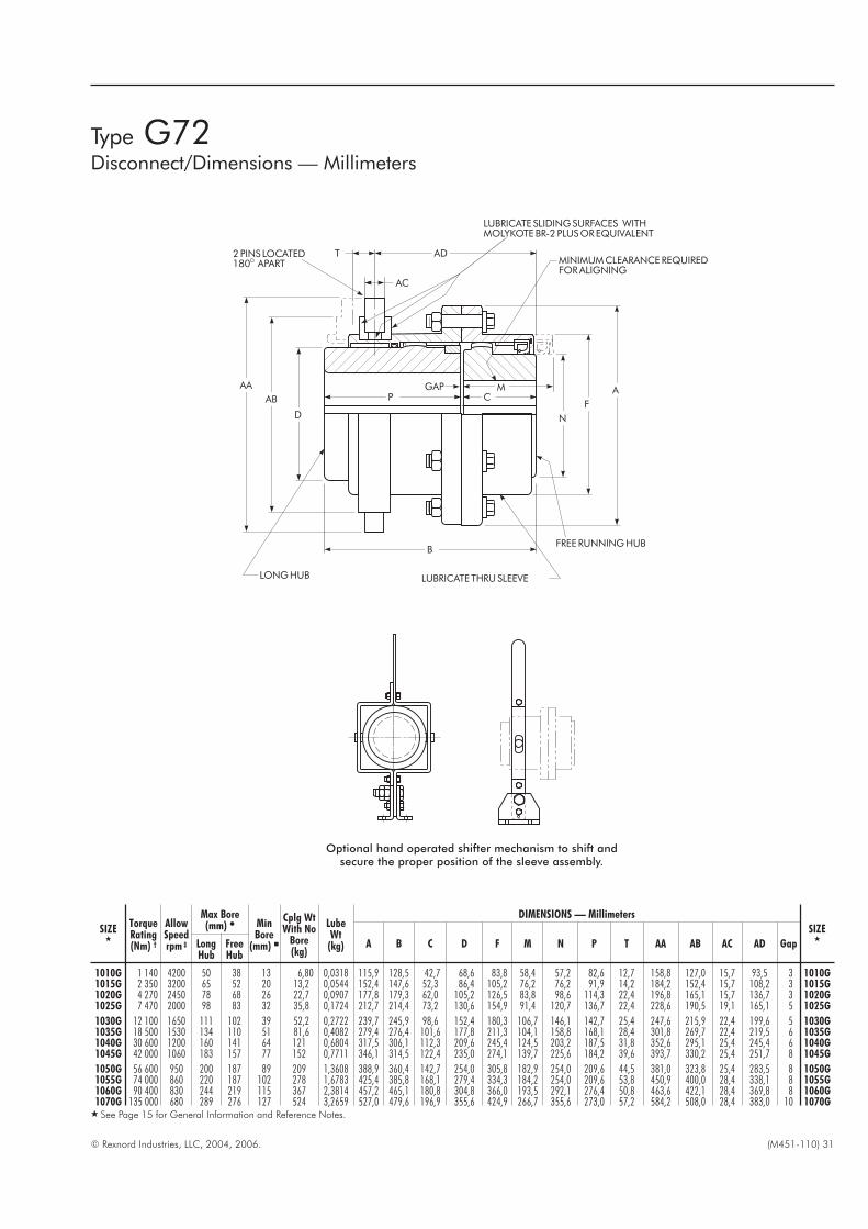
© Rexnord Industries, LLC, 2004, 2006. (M451-110) 31
SIZE�
TorqueRating(Nm) †
AllowSpeedrpm ‡
Max Bore(mm) � Min
Bore(mm) �
Cplg WtWith No
Bore(kg)
LubeWt
(kg)
DIMENSIONS — Millimeters
SIZE�
A B C D F M N P T AA AB AC AD GapLongHub
FreeHub
1010G 1 140 4200 50 38 13 6,80 0,0318 115,9 128,5 42,7 68,6 83,8 58,4 57,2 82,6 12,7 158,8 127,0 15,7 93,5 3 1010G1015G 2 350 3200 65 52 20 13,2 0,0544 152,4 147,6 52,3 86,4 105,2 76,2 76,2 91,9 14,2 184,2 152,4 15,7 108,2 3 1015G1020G 4 270 2450 78 68 26 22,7 0,0907 177,8 179,3 62,0 105,2 126,5 83,8 98,6 114,3 22,4 196,8 165,1 15,7 136,7 3 1020G1025G 7 470 2000 98 83 32 35,8 0,1724 212,7 214,4 73,2 130,6 154,9 91,4 120,7 136,7 22,4 228,6 190,5 19,1 165,1 5 1025G
1030G 12 100 1650 111 102 39 52,2 0,2722 239,7 245,9 98,6 152,4 180,3 106,7 146,1 142,7 25,4 247,6 215,9 22,4 199,6 5 1030G1035G 18 500 1530 134 110 51 81,6 0,4082 279,4 276,4 101,6 177,8 211,3 104,1 158,8 168,1 28,4 301,8 269,7 22,4 219,5 6 1035G1040G 30 600 1200 160 141 64 121 0,6804 317,5 306,1 112,3 209,6 245,4 124,5 203,2 187,5 31,8 352,6 295,1 25,4 245,4 6 1040G1045G 42 000 1060 183 157 77 152 0,7711 346,1 314,5 122,4 235,0 274,1 139,7 225,6 184,2 39,6 393,7 330,2 25,4 251,7 8 1045G
1050G 56 600 950 200 187 89 209 1,3608 388,9 360,4 142,7 254,0 305,8 182,9 254,0 209,6 44,5 381,0 323,8 25,4 283,5 8 1050G1055G 74 000 860 220 187 102 278 1,6783 425,4 385,8 168,1 279,4 334,3 184,2 254,0 209,6 53,8 450,9 400,0 28,4 338,1 8 1055G1060G 90 400 830 244 219 115 367 2,3814 457,2 465,1 180,8 304,8 366,0 193,5 292,1 276,4 50,8 463,6 422,1 28,4 369,8 8 1060G1070G 135 000 680 289 276 127 524 3,2659 527,0 479,6 196,9 355,6 424,9 266,7 355,6 273,0 57,2 584,2 508,0 28,4 383,0 10 1070G
� See Page 15 for General Information and Reference Notes.
Optional hand operated shifter mechanism to shift andsecure the proper position of the sleeve assembly.
Type G72Disconnect/Dimensions — Millimeters
MC
N
F
A
AC
LUBRICATE SLIDINGSURFACES WITHMOLYKOTEBR-2 PLUSOREQUIVALENT
T
P
D
B
LONGHUB
FREE RUNNINGHUB
MINIMUMCLEARANCEREQUIREDFORALIGNING
AB
AD
AA GAP
2PINS LOCATED180 APART
LUBRICATE THRUSLEEVE
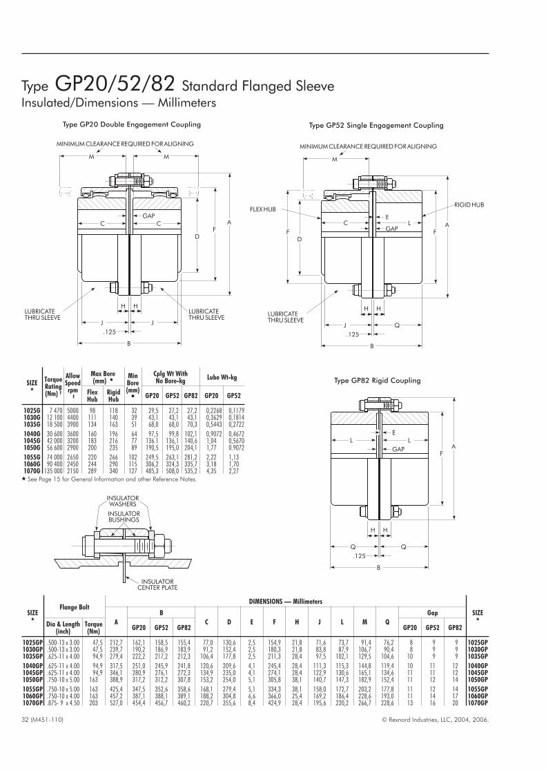
32 (M451-110) © Rexnord Industries, LLC, 2004, 2006.
SIZE�
Flange BoltDIMENSIONS — Millimeters
SIZE�
A
B
C D E F H J L M Q
Gap
Dia & Length(inch)
Torque(Nm)
GP20 GP52 GP82 GP20 GP52 GP82
1025GP .500-13 x 3.00 47,5 212,7 162,1 158,5 155,4 77,0 130,6 2,5 154,9 21,8 71,6 73,7 91,4 76,2 8 9 9 1025GP1030GP .500-13 x 3.00 47,5 239,7 190,2 186,9 183,9 91,2 152,4 2,5 180,3 21,8 83,8 87,9 106,7 90,4 8 9 9 1030GP1035GP .625-11 x 4.00 94,9 279,4 222,2 217,2 212,3 106,4 177,8 2,5 211,3 28,4 97,5 102,1 129,5 104,6 10 9 9 1035GP
1040GP .625-11 x 4.00 94,9 317,5 251,0 245,9 241,8 120,6 209,6 4,1 245,4 28,4 111,3 115,3 144,8 119,4 10 11 12 1040GP1045GP .625-11 x 4.00 94,9 346,1 280,9 276,1 272,3 134,9 235,0 4,1 274,1 28,4 122,9 130,6 165,1 134,6 11 11 12 1045GP1050GP .750-10 x 5.00 163 388,9 317,2 312,2 307,8 153,2 254,0 5,1 305,8 38,1 140,7 147,3 182,9 152,4 11 12 14 1050GP
1055GP .750-10 x 5.00 163 425,4 347,5 352,6 358,6 168,1 279,4 5,1 334,3 38,1 158,0 172,7 203,2 177,8 11 12 14 1055GP1060GP .750-10 x 4.00 163 457,2 387,1 388,1 389,1 188,2 304,8 6,6 366,0 25,4 169,2 186,4 228,6 193,0 11 14 17 1060GP1070GP .875- 9 x 4.50 203 527,0 454,4 456,7 460,2 220,7 355,6 8,4 424,9 28,4 195,6 220,2 266,7 228,6 13 16 20 1070GP
SIZE�
TorqueRating(Nm) †
AllowSpeedrpm
‡
Max Bore(mm) �
MinBore(mm)�
Cplg Wt WithNo Bore-kg
Lube Wt-kg
FlexHub
RigidHub
GP20 GP52 GP82 GP20 GP52
1025G 7 470 5000 98 118 32 29,5 27,2 27,2 0,2268 0,11791030G 12 100 4400 111 140 39 43,1 43,1 43,1 0,3629 0,18141035G 18 500 3900 134 163 51 68,0 68,0 70,3 0,5443 0,2722
1040G 30 600 3600 160 196 64 97,5 99,8 102,1 0,9072 0,46721045G 42 000 3200 183 216 77 136.1 136,1 140,6 1,04 0,56701050G 56 600 2900 200 235 89 190,5 195,0 204,1 1,77 0.9072
1055G 74 000 2650 220 266 102 249,5 263,1 281,2 2,22 1,131060G 90 400 2450 244 290 115 306,2 324,3 335,7 3,18 1,701070G 135 000 2150 289 340 127 485,3 508,0 535,2 4,35 2,27
� See Page 15 for General Information and other Reference Notes.
Type GP20/52/82 Standard Flanged SleeveInsulated/Dimensions — Millimeters
C
M M
C
JJ
.125
GAP
B
H H
DF
A
LUBRICATETHRUSLEEVE
LUBRICATETHRUSLEEVE
MINIMUMCLEARANCEREQUIREDFORALIGNING
L
.125
E
GAP
B
H H
FA
L
D
C
M
L
QJ
.125
E
GAP
B
H H
FFA
LUBRICATETHRUSLEEVE
MINIMUMCLEARANCEREQUIREDFORALIGNING
RIGIDHUBFLEXHUB
Type GP82 Rigid Coupling
Type GP20 Double Engagement Coupling Type GP52 Single Engagement Coupling
INSULATORBUSHINGS
INSULATORWASHERS
INSULATORCENTER PLATE
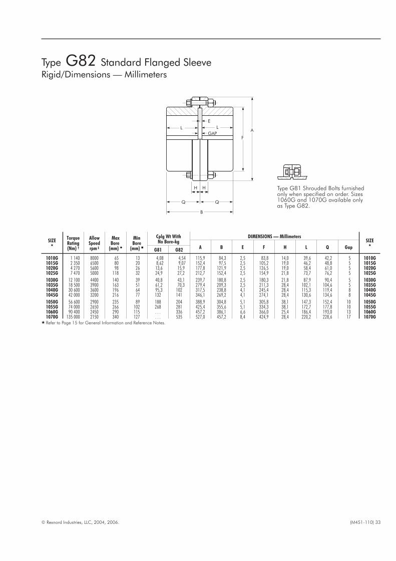
© Rexnord Industries, LLC, 2004, 2006. (M451-110) 33
SIZE�
TorqueRating(Nm) †
AllowSpeedrpm ‡
MaxBore
(mm) �
MinBore
(mm) �
Cplg Wt WithNo Bore-kg
DIMENSIONS — MillimetersSIZE
�A B E F H L Q Gap
G81 G82
1010G 1 140 8000 65 13 4,08 4,54 115,9 84,3 2,5 83,8 14,0 39,6 42,2 5 1010G1015G 2 350 6500 80 20 8,62 9,07 152,4 97,5 2,5 105,2 19,0 46,2 48,8 5 1015G1020G 4 270 5600 98 26 13,6 15,9 177,8 121,9 2,5 126,5 19,0 58,4 61,0 5 1020G1025G 7 470 5000 118 32 24,9 27,2 212,7 152,4 2,5 154,9 21,8 73,7 76,2 5 1025G
1030G 12 100 4400 140 39 40,8 43,1 239,7 180,8 2,5 180,3 21,8 87,9 90,4 5 1030G1035G 18 500 3900 163 51 61,2 70,3 279,4 209,3 2,5 211,3 28,4 102,1 104,6 5 1035G1040G 30 600 3600 196 64 95,3 102 317,5 238,8 4,1 245,4 28,4 115,3 119,4 8 1040G1045G 42 000 3200 216 77 132 141 346,1 269,2 4,1 274,1 28,4 130,6 134,6 8 1045G
1050G 56 600 2900 235 89 188 204 388,9 304,8 5,1 305,8 38,1 147,3 152,4 10 1050G1055G 74 000 2650 266 102 268 281 425,4 355,6 5,1 334,3 38,1 172,7 177,8 10 1055G1060G 90 400 2450 290 115 . . . 336 457,2 386,1 6,6 366,0 25,4 186,4 193,0 13 1060G1070G 135 000 2150 340 127 . . . 535 527,0 457,2 8,4 424,9 28,4 220,2 228,6 17 1070G
� Refer to Page 15 for General Information and Reference Notes.
L L
F
A
H
Q Q
B
GAP
E
H
Type G82 Standard Flanged SleeveRigid/Dimensions — Millimeters
Type G81 Shrouded Bolts furnishedonly when specified on order. Sizes1060G and 1070G available onlyas Type G82.

34 (M451-110) © Rexnord Industries, LLC, 2004, 2006.
SIZE�
TorqueRating(Nm) †
Hub BoreRange(mm) �
Cplg WtWith NoBore-kg
DIMENSIONS — Millimeters
SIZE�
A B E F H L Q U
W
X GapDowel Diax Length
DowelHole-Dia+.0,0127– .0,0000
1010GV 1 140 34,9 – 57,2 4,5 115,9 84,3 2,5 83,8 14,0 39,6 42,2 9,7 9,5 x 81,8 9,5 8,7 5 1010GV1015GV 2 350 41,3 – 69,8 9,1 152,4 97,5 2,5 105,2 19,0 46,2 48,8 12,7 12,7 x 103,1 12,7 11,9 5 1015GV1020GV 4 270 63,5 – 82,6 15,9 177,8 121,9 2,5 126,5 19,0 58,4 61,0 19,1 19,1 x 124,0 19,0 18,3 5 1020GV1025GV 7 470 82,6 – 101,6 27,2 212,7 152,4 2,5 154,9 21,8 73,7 76,2 25,4 25,4 x 151,9 25,4 23,8 5 1025GV
1030GV 12 100 88,9 – 114,3 43,1 239,7 180,8 2,5 180,3 21,8 87,9 90,4 28,4 28,6 x 176,8 28,5 27,0 5 1030GV1035GV 18 500 101,6 – 133,4 70,3 279,4 209,3 2,5 211,3 28,4 102,1 104,6 31,8 31,8 x 208,3 31,7 30,2 5 1035GV1040GV 30 600 114.3 – 158,8 102 317,5 238,8 4,1 245,4 28,4 115,3 119,4 35,1 34,9 x 241,8 34,9 33,4 8 1040GV1045GV 42 000 127,0 – 177,8 141 346,1 269,2 4,1 274,1 28,4 130,6 134,6 38,1 38,1 x 270,3 38,1 36,5 8 1045GV
1050GV 56 600 146,0 – 196,8 204 388,9 304,8 5,1 305,8 38,1 147,3 152,4 44,5 44,4 x 301,2 44,4 42,9 10 1050GV1055GV 74 000 146,0 – 215,9 281 425,4 355,6 5,1 334,3 38,1 172,7 177,8 44,5 44,4 x 330,2 44,4 42,9 10 1055GV1060GV 90 400 171,4 – 235,0 336 457,2 386,1 6,6 366,0 25,4 186,4 193,0 50,8 50,8 x 361,2 50,8 49,2 13 1060GV1070GV 135 000 171,4 – 273,1 535 527,0 457,2 8,4 424,9 28,4 220,2 228,6 50,8 50,8 x 420,6 50,8 49,2 17 1070GV
� Refer to Page 15 for General Information and other Reference Notes.� Dowels: diameters, +0,000,-.0,025 mm material, AISI 4140 hardness, 310-350HB; furnished by the Factory . Customer is responsible for checking and furnishing driven shaft
with satisfactory capacity.
RIGID COUPLING
MIXER SHAFT
Type GV82 Standard Flanged SleeveRigid Thrust/Dimensions — Millimeters
Q
GAPL
F
KEYWAY
A
L
U
U
Q
BH
HE
X-
W
DIAMETER PILOTHOLETHRUONEWALL INEACHHUBAT90 TOKEYWAYFOR -DOWEL. AFTERMOUNTINGHUBS,DRILLANDREAMTHRUFOR0,0254mmTIGHTTO0,0127mmLOOSEDOWELFIT. STAKEDOWELSINPLACE.
DOWELPINS
Type GV82 couplings are used as rigid connections for the lowspeed shaft of a gear drive and a mixer shaft or suspended load.The coupling carries the torque load, weight of the shaft andimpeller, thrust forces and resulting bending moments.
When a rigid coupling is required, the following additionalinformationis necessary.
1. Required thrust capacity and direction of thrust.
2. Radial force at impeller.
3. Distance from the center of coupling fastener flange to thecenter of the impeller.
4. Weight of shaft and impeller.
KEEPER PLATE REGISTERED KEEPER PLATE WELDED
OTHER AXIAL RETENTION OPTIONS — AVAILABLE ON TYPE GXVF(Refer to the Factory )
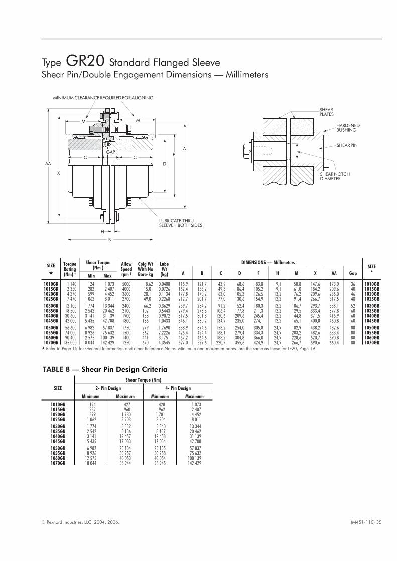
© Rexnord Industries, LLC, 2004, 2006. (M451-110) 35
SIZE
�
TorqueRating(Nm) †
Shear Torque(Nm )
AllowSpeedrpm ‡
Cplg WtWith NoBore-kg
LubeWt
(kg)
DIMENSIONS — MillimetersSIZE
�A B C D F H M X AA Gap
Min Max
1010GR 1 140 124 1 073 5000 8,62 0,0408 115,9 121,7 42,9 68,6 83,8 9,1 50,8 147,6 173,0 36 1010GR1015GR 2 350 282 2 407 4000 15,0 0,0726 152,4 138,2 49,3 86,4 105,2 9,1 61,0 184,2 209,6 40 1015GR1020GR 4 270 599 4 452 3600 28,1 0,1134 177,8 170,2 62,0 105,2 126,5 12,2 76,2 209,6 235,0 46 1020GR1025GR 7 470 1 062 8 011 2700 49,0 0,2268 212,7 201,7 77,0 130,6 154,9 12,2 91,4 266,7 317,5 48 1025GR
1030GR 12 100 1 774 13 344 2400 66,2 0,3629 239,7 234,2 91,2 152,4 180,3 12,2 106,7 293,7 338,1 52 1030GR1035GR 18 500 2 542 20 462 2100 102 0,5443 279,4 273,3 106,4 177,8 211,3 12,2 129,5 333,4 377,8 60 1035GR1040GR 30 600 3 141 31 139 1900 138 0,9072 317,5 301,8 120,6 209,6 245,4 12,2 144,8 371,5 415,9 60 1040GR1045GR 42 000 5 435 42 708 1800 185 1,0433 346,1 330,2 134,9 235,0 274,1 12,2 165,1 400,0 450,8 60 1045GR
1050GR 56 600 6 982 57 837 1750 279 1,7690 388,9 394,5 153,2 254,0 305,8 24,9 182,9 438,2 482,6 88 1050GR1055GR 74 000 8 926 75 632 1500 362 2,2226 425,4 424,4 168,1 279,4 334,3 24,9 203,2 482,6 533,4 88 1055GR1060GR 90 400 12 575 100 139 1400 441 3,1751 457,2 464,6 188,2 304,8 366,0 24,9 228,6 520,7 590,8 88 1060GR1070GR 135 000 18 044 142 429 1250 670 4,3545 527,0 529,6 220,7 355,6 424,9 24,9 266,7 590,6 660,4 88 1070GR
� Refer to Page 15 for General Information and other Reference Notes. Minimum and maximum bores are the same as those for G20, Page 19.
B
AA
GAP
X
M
D
F
A
M
H
MINIMUMCLEARANCEREQUIREDFORALIGNING
LUBRICATE THRUSLEEVE - BOTH SIDES
CC
Type GR20 Standard Flanged SleeveShear Pin/Double Engagement Dimensions — Millimeters
SHEARPLATES
HARDENEDBUSHING
SHEARPIN
SHEARNOTCHDIAMETER
TABLE 8 — Shear Pin Design Criteria
SIZE
Shear Torque (Nm)
2- Pin Design 4- Pin Design
Minimum Maximum Minimum Maximum
1010GR 124 427 428 1 0731015GR 282 960 962 2 4071020GR 599 1 780 1 781 4 4521025GR 1 062 3 203 3 204 8 011
1030GR 1 774 5 339 5 340 13 3441035GR 2 542 8 186 8 187 20 4621040GR 3 141 12 457 12 458 31 1391045GR 5 435 17 083 17 084 42 708
1050GR 6 982 23 134 23 135 57 8371055GR 8 926 30 257 30 258 75 6321060GR 12 575 40 053 40 054 100 1391070GR 18 044 56 944 56 945 142 429

36 (M451-110) © Rexnord Industries, LLC, 2004, 2006.
TABLE 9 — Standard AISE AC & DC Mill Motor Coupling Selections
Motor Frame SizesCOUPLING
SIZE�
E(mm)
R(mm)
UG(mm)
UH(mm)
Keyway(mm)
Z(mm)
ZD(mm)
ZE
(mm)ZG
(mm)
ZH (mm)+,XXX
– ,000
2602
802A, B & C
AC1, 2 & 4
1015G 2,57,9 36,5 44,4 12,7 x .6,4 82,6 23,9 76,2
1,50,61020G 2,5 5,6
1025G 2,5 12,4
603604
803804
. . .
1015G 2,5
9,7 41,5 50,8 12,7 x 6,4 85,7 25,4 88,9
0,0
0,71020G 2,5 4,11025G 2,5 10,91030G 2,5 19,1
606 806AC
8 &12
1020G 2,5
9,7 52,9 63,5 12,7 x 6,4 101,6 28,4 101,6
1,0
0,71025G 2,5 7,61030G 2,5 15,71035G 2,5 25,4
608 808 . . .
1025G 2,5
12,7 64,3 76,2 19,0 x 6,4 133,4 31,8 114,3
4,6
0,71030G 2,5 12,71035G 2,5 22,41040G 4,1 32,0
610 810 AC180
1025G 2,5
12,7 70,6 82,6 19,0 x 6,4 142,9� 35,1 114,3
1,3
0,91030G 2,5 9,71035G 2,5 19,31040G 4,1 29,0
612 812AC
25 & 30
1030G 2,5
12,7 78,8 92,1 19,0 x 6,4 158,8 38,1 127,0
6,4
0,91035G 2,5 16,01040G 4,1 25,71045G 4,1 32,3
614 814AC
40 & 50
1035G 2,5
12,7 94,7 108,0 25,4 x 9,5 174,6 41,1 127,0
12,7
0,91040G 4,1 22,61045G 4,1 29,21050G 5,1 40,6
616 816 . . .
1035G 2,5
15,7 102,9
115,8 �
31,8 x 9,5
195,3
44,4
123,7 � 9,7
0,91040G 4,1 117,5 200,0 139,7 19,31045G 4,1 117,5 200,0 139,7 25,91050G 5,1 117,5 200,0 139,7 37,1
618 818 . . .1040G 4,1
15,7 111,1 127,0 31,8 x 12,7 212,7 33,5 152,430,5
1,01045G 4,1 37,31050G 5,1 48,5
620 820 . . .1045G 4,1
19,0 131,4 149,2 38,1 x 19,0 247,6 44,4 171,425,9
1,01050G 5,1 37,31055G 5,1 51,3
622 822 . . .
1045G 4,1
19,0 139,6 158,8 38,1 x 19,0 247,6 60,2 184,2
10,2
1,01050G 5,1 21,61055G 5,1 35,31060G 6,6 41,7
624 824 . . .
1050G 5,1
19,0 153,3 177,8 38,1 x 19,0 247,6 60,2 235,0
21,3
1,01055G 5,1 35,31060G 6,6 41,71070G 8,4 59,7
� See Page 15 for General Information and other Reference Notes. Minimum coupling selections are based on coupling borecapacity. Check coupling rating for all selections. Refer to Pages 19 & 21 for coupling dimensions.
� Spanner wrench required for Size 1025G.� For rigid hub only.
TABLE 10 — Taper and Counterbore Limitations/Metric Equivalent Dimensions — Millimeters �
SIZE�
Flex Hub Rigid Hub SIZE�
P Max � UG Min UH Max � ZD Max ZE Min P Max � UG Min UH Max � ZD Max ZE Min
1010G 101,6 12,7 50 18,5 42,9 104,1 12,7 65 76,2 39,6 1010G1015G 114,3 19,0 65 25,4 49,3 116,8 19,0 80 85,9 46,2 1015G1020G 130,0 25,4 78 29,5 62,0 132,6 25,4 98 101,6 58,4 1020G1025G 149,4 31,8 98 36,3 77,0 151,9 31,8 118 142,7 73,7 1025G
1030G 165,1 38,1 111 44,4 91,2 167,6 38,1 140 158,8 87,9 1030G1035G 184,2 50,8 134 54,1 106,4 170,7 50,8 163 174,8 102,1 1035G1040G 203,2 63,5 160 63,8 120,6 191,0 63,5 196 212,9 114,3 1040G1045G 244,3 76,2 183 70,4 134,9 249,4 76,2 216 247,6 129,5 1045G
1050G 295,1 88,9 200 81,8 153,2 300,2 88,9 235 273,0 147,3 1050G1055G 298,4 101,6 220 95,8 168,1 303,3 101,6 266 298,5 172,7 1055G1060G 304,8 114,3 244 102,1 188,2 311,2 114,3 290 330,2 186,4 1060G1070G 309,9 127,0 289 120,1 220,7 312,9 127,0 340 381,0 220,2 1070G
� This table specifies the taper bore limitations for the usual requirements. For hubs longer than those listed, refer to the Factory.� Standard Long Hub length, consult the Factory for longer lengths.� Keyway for keys shown in Table 11, Page 37.
Type G Standard Flanged SleeveMill Motor & Taper Bores/Metric Equivalent Dimensions — Millimeters
ZE
UHUG
P
ZG
ZD ZH
AMOUNT MACHINED FROMHUB FACE ON GAP SIDE
ZE
UH
UG
P
R
EZD
ZH
Z
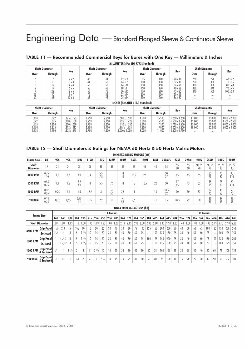
© Rexnord Industries, LLC, 2004, 2006. (M451-110) 37
TABLE 11 — Recommended Commercial Keys for Bores with One Key — Millimeters & Inches
MILLIMETERS (Per ISO R773 Standard)
Shaft DiameterKey
Shaft DiameterKey
Shaft DiameterKey
Shaft DiameterKey
Over Through Over Through Over Through Over Through
6 8 2 x 2 38 44 12 x 8 95 110 28 x 16 260 290 63 x 328 10 3 x 3 44 50 14 x 9 110 130 32 x 18 290 330 70 x 36
10 12 4 x 4 50 58 16 x 10 130 150 36 x 20 330 380 80 x 4012 17 5 x 5 58 65 18 x 11 150 170 40 x 22 380 440 90 x 4517 22 6 x 6 65 75 20 x 12 170 200 45 x 25 440 500 100 x 5022 30 8 x 7 75 85 22 x 14 200 230 50 x 28 . . . . . . . . .30 38 10 x 8 85 95 25 x 14 230 260 56 x 32 . . . . . . . . .
INCHES (Per ANSI B17.1 Standard)
Shaft DiameterKey
Shaft DiameterKey
Shaft DiameterKey
Shaft DiameterKey
Over Through Over Through Over Through Over Through
.438 .562 .125 x .125 1.750 2.250 .500 x .500 4.500 5.500 1.250 x 1.250 11.000 13.000 3.000 x 2.000
.562 .875 .188 x .188 2.250 2.750 .625 x .625 5.500 6.500 1.500 x 1.500 13.000 15.000 3.500 x 2.500
.875 1.250 .250 x .250 2.750 3.250 .750 x .750 6.500 7.500 1.750 x 1.500 15.000 18.000 4.000 x 3.0001.250 1.375 .312 x .312 3.250 3.750 .875 x .875 7.500 9.000 2.000 x 1.500 18.000 22.000 5.000 x 3.5001.375 1.750 .375 x .375 3.750 4.500 1.000 x 1.000 9.000 11.000 2.500 x 1.750 . . . . . . . . .
Engineering Data — Standard Flanged Sleeve & Continuous Sleeve
NEMA 60 HERTZ MOTORS (hp)
Frame SizeT Frames TS Frames
143 145 182 184 213 215 254 256 284 286 324 326 364 365 404 405 444 445 284 286 324 326 364 365 404 405 444 445
Shaft Diameter .88 .88 1.13 1.13 1.38 1.38 1.63 1.63 1.88 1.88 2.13 2.13 2.38 2.38 2.88 2.88 3.38 3.38 1.63 1.63 1.88 1.88 1.88 1.88 2.13 2.13 2.38 2.38
3600 RPMDrip Proof 1 1/2 2-3 5 7 1/2 10 15 20 25 30 40 50 60 75 100 125 150 200 250 30 40 50 60 75 100 125 150 200 250
Enclosed 1 1/2 2 3 5 7 1/2 10 15 20 25 30 40 50 60 75 . . . 100 125 150 25 30 40 50 60 75 . . . 100 125 150
1800 RPMDrip Proof 1 1 1/2-2 3 5 7 1/2 10 15 20 25 30 40 50 60 75 100 125 150 200 25 30 40 50 60 75 100 125 150 200
Enclosed 1 1 1/2-2 3 5 7 1/2 10 15 20 25 30 40 50 60 75 . . . 100 125 150 25 30 40 50 60 75 . . . 100 125 150
1200 RPMDrip Proof& Enclosed
3/4 1 1 1/2 2 3 5 7 1/2 10 15 20 25 30 40 50 60 75 100 125 15 20 25 30 40 50 60 75 100 125
900 RPMDrip Proof& Enclosed
1/2 3/4 1 1 1/2 2 3 5 7 1/2 10 15 20 25 30 40 50 60 75 100 10 15 20 25 30 40 50 60 75 100
TABLE 12 — Shaft Diameters & Ratings for NEMA 60 Hertz & 50 Hertz Metric Motors
50 HERTZ METRIC MOTORS (kW)
Frame Size 80 90S 90L 100L 112M 132S 132M 160M 160L 180M 180L 200M/L 225S 225M 250S 250M 280S 280M
ShaftDiameter
19 24 24 28 28 38 38 42 42 48 48 555560
5560
60, 6570
60, 6570
65, 7580
65, 7580
3000 RPM0,751,10
1,5 2,2 3,0 45,57,5
1115
18,5 223037
45 45 555575
7590
90110
1500 RPM0,550,75
1,1 1,52,23,0
4 5,5 7,5 11 15 18,5 22 303745
45 555575
7590
90110
1000 RPM0,370,55
0,75 1,1 1,5 2,2 34
5,57,5 11 15
18,522
30 30 373745
4550
5575
750 RPM0,180,25
0,37 0,550,751,1
1,5 2,2 34
5,57,5 11 15 18,5 22 30
3037
3745
4555
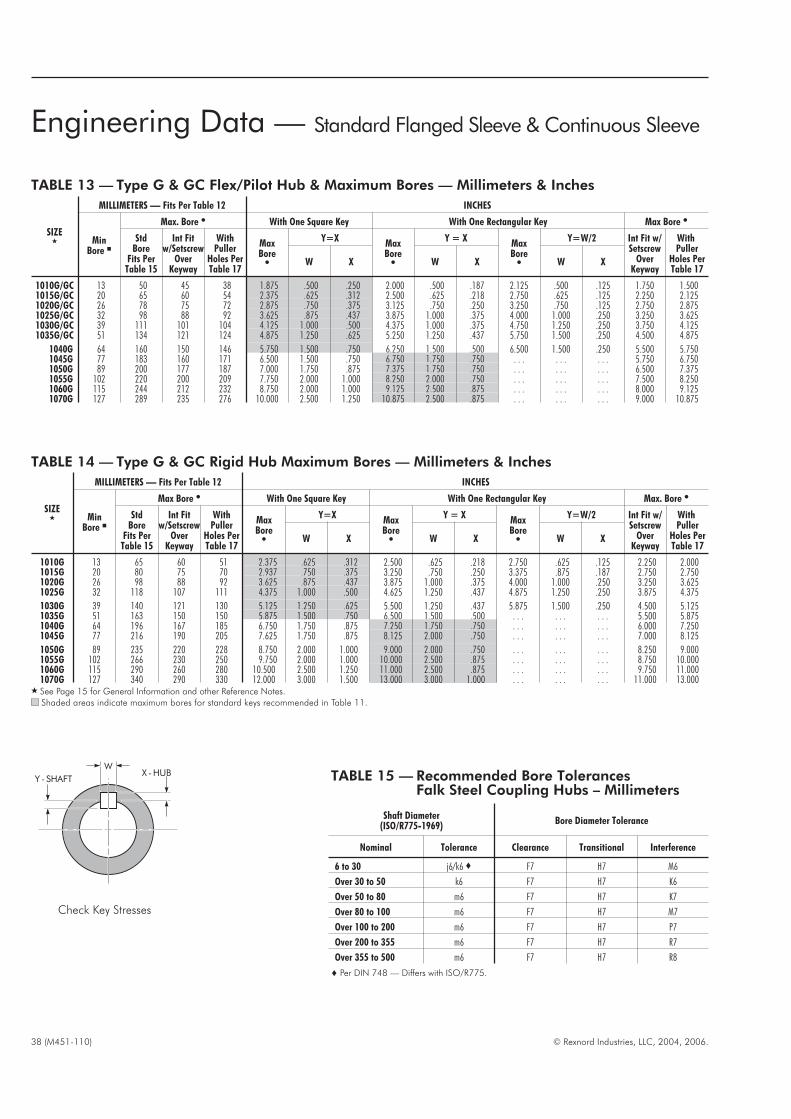
38 (M451-110) © Rexnord Industries, LLC, 2004, 2006.
TABLE 13 — Type G & GC Flex/Pilot Hub & Maximum Bores — Millimeters & Inches
SIZE�
MILLIMETERS — Fits Per Table 12 INCHES
MinBore �
Max. Bore � With One Square Key With One Rectangular Key Max Bore �
StdBore
Fits PerTable 15
Int Fitw/Setscrew
OverKeyway
WithPuller
Holes PerTable 17
MaxBore�
Y=XMaxBore�
Y = XMaxBore�
Y=W/2 Int Fit w/Setscrew
OverKeyway
WithPuller
Holes PerTable 17
W X W X W X
1010G/GC 13 50 45 38 1.875 .500 .250 2.000 .500 .187 2.125 .500 .125 1.750 1.5001015G/GC 20 65 60 54 2.375 .625 .312 2.500 .625 .218 2.750 .625 .125 2.250 2.1251020G/GC 26 78 75 72 2.875 .750 .375 3.125 .750 .250 3.250 .750 .125 2.750 2.8751025G/GC 32 98 88 92 3.625 .875 .437 3.875 1.000 .375 4.000 1.000 .250 3.250 3.6251030G/GC 39 111 101 104 4.125 1.000 .500 4.375 1.000 .375 4.750 1.250 .250 3.750 4.1251035G/GC 51 134 121 124 4.875 1.250 .625 5.250 1.250 .437 5.750 1.500 .250 4.500 4.875
1040G 64 160 150 146 5.750 1.500 .750 6.250 1.500 .500 6.500 1.500 .250 5.500 5.7501045G 77 183 160 171 6.500 1.500 .750 6.750 1.750 .750 . . . . . . . . . 5.750 6.7501050G 89 200 177 187 7.000 1.750 .875 7.375 1.750 .750 . . . . . . . . . 6.500 7.3751055G 102 220 200 209 7.750 2.000 1.000 8.250 2.000 .750 . . . . . . . . . 7.500 8.2501060G 115 244 212 232 8.750 2.000 1.000 9.125 2.500 .875 . . . . . . . . . 8.000 9.1251070G 127 289 235 276 10.000 2.500 1.250 10.875 2.500 .875 . . . . . . . . . 9.000 10.875
Y - SHAFTX -HUB
W
TABLE 14 — Type G & GC Rigid Hub Maximum Bores — Millimeters & Inches
SIZE�
MILLIMETERS — Fits Per Table 12 INCHES
MinBore �
Max Bore � With One Square Key With One Rectangular Key Max. Bore �
StdBore
Fits PerTable 15
Int Fitw/Setscrew
OverKeyway
WithPuller
Holes PerTable 17
MaxBore�
Y=XMaxBore�
Y = XMaxBore�
Y=W/2 Int Fit w/Setscrew
OverKeyway
WithPuller
Holes PerTable 17
W X W X W X
1010G 13 65 60 51 2.375 .625 .312 2.500 .625 .218 2.750 .625 .125 2.250 2.0001015G 20 80 75 70 2.937 .750 .375 3.250 .750 .250 3.375 .875 .187 2.750 2.7501020G 26 98 88 92 3.625 .875 .437 3.875 1.000 .375 4.000 1.000 .250 3.250 3.6251025G 32 118 107 111 4.375 1.000 .500 4.625 1.250 .437 4.875 1.250 .250 3.875 4.375
1030G 39 140 121 130 5.125 1.250 .625 5.500 1.250 .437 5.875 1.500 .250 4.500 5.1251035G 51 163 150 150 5.875 1.500 .750 6.500 1.500 .500 . . . . . . . . . 5.500 5.8751040G 64 196 167 185 6.750 1.750 .875 7.250 1.750 .750 . . . . . . . . . 6.000 7.2501045G 77 216 190 205 7.625 1.750 .875 8.125 2.000 .750 . . . . . . . . . 7.000 8.125
1050G 89 235 220 228 8.750 2.000 1.000 9.000 2.000 .750 . . . . . . . . . 8.250 9.0001055G 102 266 230 250 9.750 2.000 1.000 10.000 2.500 .875 . . . . . . . . . 8.750 10.0001060G 115 290 260 280 10.500 2.500 1.250 11.000 2.500 .875 . . . . . . . . . 9.750 11.0001070G 127 340 290 330 12.000 3.000 1.500 13.000 3.000 1.000 . . . . . . . . . 11.000 13.000
� See Page 15 for General Information and other Reference Notes.
Shaded areas indicate maximum bores for standard keys recommended in Table 11.
Check Key Stresses
TABLE 15 — Recommended Bore TolerancesFalk Steel Coupling Hubs – Millimeters
Shaft Diameter(ISO/R775-1969)
Bore Diameter Tolerance
Nominal Tolerance Clearance Transitional Interference
6 to 30 j6/k6 � F7 H7 M6
Over 30 to 50 k6 F7 H7 K6
Over 50 to 80 m6 F7 H7 K7
Over 80 to 100 m6 F7 H7 M7
Over 100 to 200 m6 F7 H7 P7
Over 200 to 355 m6 F7 H7 R7
Over 355 to 500 m6 F7 H7 R8
� Per DIN 748 — Differs with ISO/R775.
Engineering Data — Standard Flanged Sleeve & Continuous Sleeve
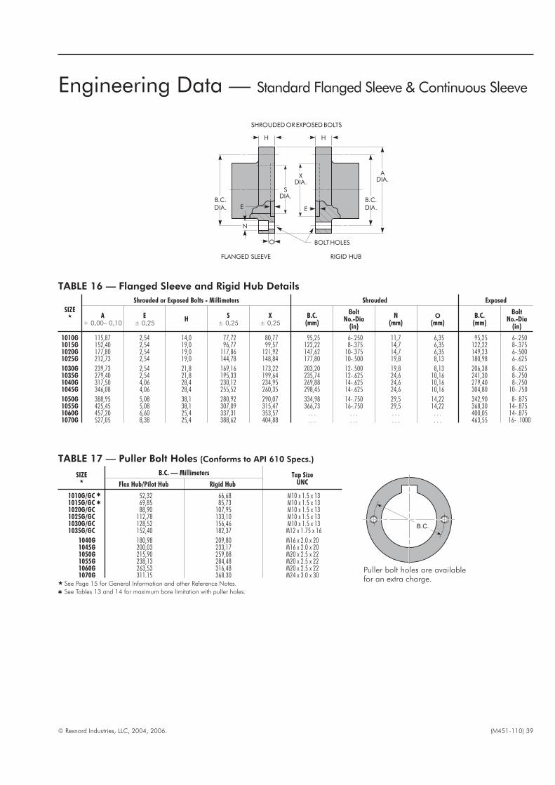
© Rexnord Industries, LLC, 2004, 2006. (M451-110) 39
TABLE 16 — Flanged Sleeve and Rigid Hub Details
SIZE�
Shrouded or Exposed Bolts - Millimeters Shrouded Exposed
A+ 0,00– 0,10
E± 0,25
HS
± 0,25X
± 0,25B.C.
(mm)
BoltNo.-Dia
(in)
N(mm)
O(mm)
B.C.(mm)
BoltNo.-Dia
(in)
1010G 115,87 2,54 14,0 77,72 80,77 95,25 6-.250 11,7 6,35 95,25 6-.2501015G 152,40 2,54 19,0 96,77 99,57 122,22 8-.375 14,7 6,35 122,22 8-.3751020G 177,80 2,54 19,0 117,86 121,92 147,62 10-.375 14,7 6,35 149,23 6-.5001025G 212,73 2,54 19,0 144,78 148,84 177,80 10-.500 19,8 8,13 180,98 6-.625
1030G 239,73 2,54 21,8 169,16 173,22 203,20 12-.500 19,8 8,13 206,38 8-.6251035G 279,40 2,54 21,8 195,33 199,64 235,74 12-.625 24,6 10,16 241,30 8-.7501040G 317,50 4,06 28,4 230,12 234,95 269,88 14-.625 24,6 10,16 279,40 8-.7501045G 346,08 4,06 28,4 255,52 260,35 298,45 14-.625 24,6 10,16 304,80 10-.750
1050G 388,95 5,08 38,1 280,92 290,07 334,98 14-.750 29,5 14,22 342,90 8- .8751055G 425,45 5,08 38,1 307,09 315,47 366,73 16-.750 29,5 14,22 368,30 14-.8751060G 457,20 6,60 25,4 337,31 353,57 . . . . . . . . . . . . 400,05 14-.8751070G 527,05 8,38 25,4 388,62 404,88 . . . . . . . . . . . . 463,55 16- .1000
E
H H
O
SDIA.
B.C.DIA.
B.C.DIA.
ADIA.
XDIA.
E
BOLTHOLES
SHROUDEDOREXPOSEDBOLTS
FLANGED SLEEVE RIGID HUB
N
TABLE 17 — Puller Bolt Holes (Conforms to API 610 Specs.)
SIZE�
B.C. — Millimeters Tap SizeUNCFlex Hub/Pilot Hub Rigid Hub
1010G/GC � 52,32 66,68 M10 x 1.5 x 131015G/GC � 69,85 85,73 M10 x 1.5 x 131020G/GC 88,90 107,95 M10 x 1.5 x 131025G/GC 112,78 133,10 M10 x 1.5 x 131030G/GC 128,52 156,46 M10 x 1.5 x 131035G/GC 152,40 182,37 M12 x 1.75 x 16
1040G 180,98 209,80 M16 x 2.0 x 201045G 200,03 233,17 M16 x 2.0 x 201050G 215,90 259,08 M20 x 2.5 x 221055G 238,13 284,48 M20 x 2.5 x 221060G 263,53 316,48 M20 x 2.5 x 221070G 311,15 368,30 M24 x 3.0 x 30
� See Page 15 for General Information and other Reference Notes.
� See Tables 13 and 14 for maximum bore limitation with puller holes.
Puller bolt holes are availablefor an extra charge.
B.C.
Engineering Data — Standard Flanged Sleeve & Continuous Sleeve
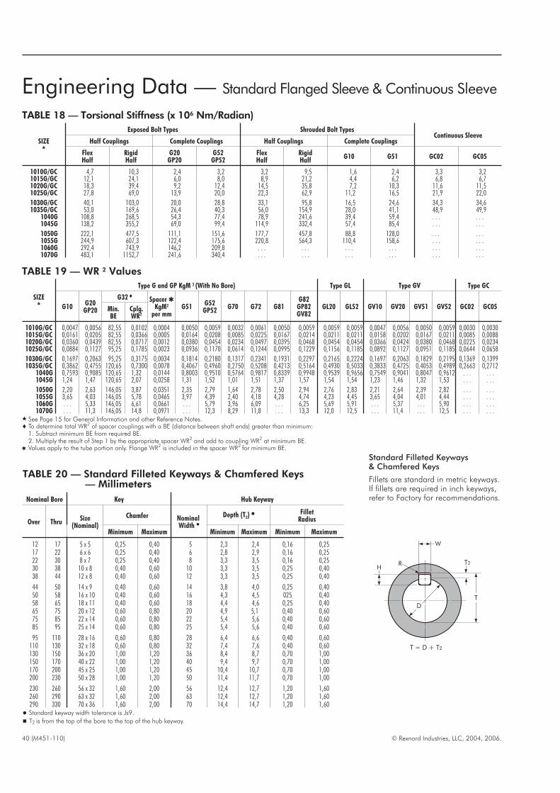
40 (M451-110) © Rexnord Industries, LLC, 2004, 2006.
TABLE 20 — Standard Filleted Keyways & Chamfered Keys— Millimeters
Nominal Bore Key Hub Keyway
Over ThruSize
(Nominal)
Chamfer NominalWidth �
Depth (T2)� Fillet
Radius
Minimum Maximum Minimum Maximum Minimum Maximum
12 17 5 x 5 0,25 0,40 5 2,3 2,4 0,16 0,2517 22 6 x 6 0,25 0,40 6 2,8 2,9 0,16 0,2522 30 8 x 7 0,25 0,40 8 3,3 3,5 0,16 0,2530 38 10 x 8 0,40 0,60 10 3,3 3,5 0,25 0,4038 44 12 x 8 0,40 0,60 12 3,3 3,5 0,25 0,40
44 50 14 x 9 0,40 0,60 14 3,8 4,0 0,25 0,4050 58 16 x 10 0,40 0,60 16 4,3 4,5 025 0,4058 65 18 x 11 0,40 0,60 18 4,4 4,6 0,25 0,4065 75 20 x 12 0,60 0,80 20 4,9 5,1 0,40 0,6075 85 22 x 14 0,60 0,80 22 5,4 5,6 0,40 0,6085 95 25 x 14 0,60 0,80 25 5,4 5,6 0,40 0,60
95 110 28 x 16 0,60 0,80 28 6,4 6,6 0,40 0,60110 130 32 x 18 0,60 0,80 32 7,4 7,6 0,40 0,60130 150 36 x 20 1,00 1,20 36 8,4 8,7 0,70 1,00150 170 40 x 22 1,00 1,20 40 9,4 9,7 0,70 1,00170 200 45 x 25 1,00 1,20 45 10,4 10,7 0,70 1,00200 230 50 x 28 1,00 1,20 50 11,4 11,7 0,70 1,00
230 260 56 x 32 1,60 2,00 56 12,4 12,7 1,20 1,60260 290 63 x 32 1,60 2,00 63 12,4 12,7 1,20 1,60290 330 70 x 36 1,60 2,00 70 14,4 14,7 1,20 1,60
� Standard keyway width tolerance is Js9.
� T2 is from the top of the bore to the top of the hub keyway.
TABLE 18 — Torsional Stiffness (x 106 Nm/Radian)
SIZE�
Exposed Bolt Types Shrouded Bolt TypesContinuous Sleeve
Half Couplings Complete Couplings Half Couplings Complete Couplings
FlexHalf
RigidHalf
G20GP20
G52GP52
FlexHalf
RigidHalf
G10 G51 GC02 GC05
1010G/GC 4,7 10,3 2,4 3,2 3,2 9,5 1,6 2,4 3,3 3,21015G/GC 12,1 24,1 6,0 8,0 8,9 21,2 4,4 6,2 6,8 6,71020G/GC 18,3 39,4 9,2 12,4 14,5 35,8 7,2 10,3 11,6 11,51025G/GC 27,8 69,0 13,9 20,0 22,3 62,9 11,2 16,5 21,9 22,0
1030G/GC 40,1 103,0 20,0 28,8 33,1 95,8 16,5 24,6 34,3 34,61035G/GC 53,0 169,6 26,4 40,3 56,0 154,9 28,0 41,1 48,9 49,9
1040G 108,8 268,5 54,3 77,4 78,9 241,6 39,4 59,4 . . . . . .1045G 138,2 355,2 69,0 99,4 114,9 332,4 57,4 85,4 . . . . . .
1050G 222,1 477,5 111,1 151,6 177,7 457,8 88,8 128,0 . . . . . .1055G 244,9 607,3 122,4 175,6 220,8 564,3 110,4 158,6 . . . . . .1060G 292,4 743,9 146,2 209,8 . . . . . . . . . . . . . . . . . .1070G 483,1 1152,7 241,6 340,4 . . . . . . . . . . . . . . . . . .
Engineering Data — Standard Flanged Sleeve & Continuous Sleeve
TABLE 19 — WR 2 Values
SIZE�
Type G and GP KgM 2 (With No Bore) Type GL Type GV Type GC
G10G20
GP20
G32 � Spacer �KgM2
per mmG51
G52GP52
G70 G72 G81G82
GP82GV82
GL20 GL52 GV10 GV20 GV51 GV52 GC02 GC05Min.BE
Cplg.WR2
1010G/GC 0,0047 0,0056 82,55 0,0102 0,0004 0,0050 0,0059 0,0032 0,0061 0,0050 0,0059 0,0059 0,0059 0,0047 0,0056 0,0050 0,0059 0,0030 0,00301015G/GC 0,0161 0,0205 82,55 0,0366 0,0005 0,0164 0,0208 0,0085 0,0225 0,0167 0,0214 0,0211 0,0211 0,0158 0,0202 0,0167 0,0211 0,0085 0,00881020G/GC 0,0360 0,0439 82,55 0,0717 0,0012 0,0380 0,0454 0,0234 0,0497 0,0395 0,0468 0,0454 0,0454 0,0366 0,0424 0,0380 0,0468 0,0225 0,02341025G/GC 0,0884 0,1127 95,25 0,1785 0,0023 0,0936 0,1170 0,0614 0,1244 0,0995 0,1229 0,1156 0,1185 0,0892 0,1127 0,0951 0,1185 0,0644 0,0658
1030G/GC 0,1697 0,2063 95,25 0,3175 0,0034 0,1814 0,2180 0,1317 0,2341 0,1931 0,2297 0,2165 0,2224 0,1697 0,2063 0,1829 0,2195 0,1369 0,13991035G/GC 0,3862 0,4755 120,65 0,7300 0,0078 0,4067 0,4960 0,2750 0,5208 0,4213 0,5164 0,4930 0,5033 0,3833 0,4725 0,4053 0,4989 0,2663 0,2712
1040G 0,7593 0,9085 120,65 1,32 0,0144 0,8003 0,9510 0,5764 0,9817 0,8339 0,9948 0,9539 0,9656 0,7549 0,9041 0,8047 0,9612 . . . . . .1045G 1,24 1,47 120,65 2,07 0,0258 1,31 1,52 1,01 1,51 1,37 1,57 1,54 1,54 1,23 1,46 1,32 1,53 . . . . . .
1050G 2,20 2,63 146,05 3,87 0,0351 2,35 2,79 1,64 2,78 2,50 2,94 2,76 2,83 2,21 2,64 2,39 2,82 . . . . . .1055G 3,65 4,03 146,05 5,78 0,0465 3,97 4,39 2,40 4,18 4,28 4,74 4,23 4,45 3,65 4,04 4,01 4,44 . . . . . .1060G . . . 5,33 146,05 6,61 0,0661 . . . 5,79 3,96 6,09 . . . 6,25 5,69 5,91 . . . 5,37 . . . 5,90 . . . . . .1070G . . . 11,3 146,05 14,8 0,0971 . . . 12,3 8,29 11,8 . . . 13,3 12,0 12,5 . . . 11,4 . . . 12,5 . . . . . .
� See Page 15 for General Information and other Reference Notes.� To determine total WR2 of spacer couplings with a BE (distance between shaft ends) greater than minimum:
1. Subtract minimum BE from required BE.2. Multiply the result of Step 1 by the appropriate spacer WR2 and add to coupling WR2 at minimum BE.
� Values apply to the tube portion only. Flange WR2 is included in the spacer WR2 for minimum BE.
H
W
T2R
T = D + T2
TD
Standard Filleted Keyways& Chamfered Keys
Fillets are standard in metric keyways.If fillets are required in inch keyways,refer to Factory for recommendations.

© Rexnord Industries, LLC, 2004, 2006. (M451-110) 41
TABLE 21 — Type G Only Variable Gap —Millimeters
SIZE�
CStd
LStd
PMax
ZDMax�
Coupling Gap
Double Engagement Single Engagement
Std Fig 1 Fig 2 Fig 3 Std Fig 4 Fig 5
1010G 42,9 39,6 101,6 18,5 3 10 7 40 4 8 231015G 49,3 46,2 114,3 25,4 3 29 16 54 4 17 291020G 62,0 58,4 130,0 29,5 3 27 15 62 4 16 331025G 77,0 73,7 149,4 36,3 5 34 19 77 5 19 41
1030G 91,2 87,9 165,1 44,4 5 45 25 94 5 25 491035G 106,4 102,1 184,2 54,1 6 61 34 115 6 33 601040G 120,6 115,3 203,2 63,8 6 61 43 134 7 44 711045G 134,9 130,6 244,3 70,4 8 86 47 149 8 47 78
1050G 153,2 147,3 295,1 81,8 8 102 55 172 9 56 911055G 168,1 172,7 298,4 95,8 8 134 71 199 9 72 1051060G 188,2 186,4 304,8 102,1 8 127 68 212 10 70 1121070G 220,7 220,2 309,9 120,1 10 150 80 250 13 83 133� See Page 15 for General Information and other Reference Notes.� Standard gap must be increased by the amount cut off the hub, to maintain the
correct flex hub tooth position.
TABLE 22 — Misalignment Capacity – Millimeters �
SIZE�
Double Engagement Single Engagement �
Angular MaximumMillimeters
RecommendedInstallation Maximum
MaximumOperating �
ParallelOffset-(mm) P
Angular(mm)
A Minus B
ParallelOffset-(mm) P
Angular(mm)
A Minus B
RecommendedInstallationA Minus B
MaximumOperating
�
A Minus B
1010G 0,05 0,15 0,66 1,80 0,15 0,891010GC 0,04 0,08 0,28 1,80 0,15 0,891015G 0,08 0,18 0,86 2,26 0,18 1,141015GC 0,04 0,18 0,43 2,26 0,18 1,141020G 0,08 0,23 1,02 2,74 0,23 1,371020GC 0,04 0,23 0,48 2,74 0,23 1,37
1025G 0,10 0,28 1,27 3,43 0,28 1,701025GC 0,05 0,28 0,61 3,43 0,28 1,701030G 0,13 0,33 1,52 3,99 0,33 2,011030GC 0,05 0,33 0,69 3,99 0,33 2,011035G 0,15 0,38 1,83 4,65 0,38 2,341035GC 0,08 0,33 0,81 4,65 0,38 2,34
1040G 0,18 0,46 2,13 5,49 0,46 2,741045G 0,20 0,51 2,39 6,15 0,51 3,071050G 0,23 0,56 2,72 6,65 0,56 3,331055G 0,28 0,61 3,12 7,32 0,61 3,661060G 0,28 0,66 3,35 7,98 0,66 3,991070G 0,33 0,79 3,94 9,32 0,79 4,65
� These maximum operating alignment limits are each based on 3/4 ° per flex halfcoupling. Combined values of parallel and angular misalignment should notexceed 3/4 °. Type GL slide couplings are limited to 1/4 ° per flex half.
� Do not use single engagement couplings to compensate for paralleloffset misalignment.
VARIABLE GAP — Normally it is not necessary to overhang gearcoupling hubs since the hubs can readily be reversed to producedifferent gap dimensions as illustrated in Figures 1, 2 and 4below. Also, long hubs from Table 10, Page 36, can be cut off tosuit required gap as illustrated in Figures 3 and 5 below.
However, when the distance between shafts is greater than theallowable coupling gap, overhang one or both hubs. It must beremembered that this practice reduces shaft-hub engagement. Ifthe overhang with a standard hub results in less than .75 timesthe shaft diameter engagement, a coupling with long hubs isrecommended. Use the standard interference fit and check keystrength.
CAUTION: The effect of open keyways on coupling balanceshould always be considered.
If axial shaft movement is required, use the Type GL slidecoupling.
MISALIGNMENT CAPACITY — Shaft misalignment can be dueto the combined effects of both parallel and angular shaftdisplacement. Falk 1000 series gear couplings are designed toaccommodate a static misalignment of 1-1/2
° per gear mesh. Therecommended installation misalignment is limited to 1/8
° per gearmesh. Axial movement of connected shafts is alsoaccommodated.
It is important that flexible couplings be properly aligned so thatthe maximum benefits of the equipment can be obtained. Thesebenefits include the following:
1. Longer coupling life with minimum maintenance.
2. Longer life of the connected equipment as a result of reducedbending moments and radial forces which are related to theamount of misalignment.
3. Permit drive systems to have reserve misalignment capacity toaccommodate unavoidable alignment changes caused bybearing wear foundation settling, thermal expansion, etc.
YYY Y
X X
Dimension Ymust beequal to orgreater thanDimension Xtimes .75.If not, uselong hubs.CC
GAP
TWO HUBS REVERSED
GAP
ONE HUB REVERSED
CC
PP
ZDCUTOFF
ZDCUTOFF
GAP
LONG HUB CUTOFF
Double Engagement Couplings
Single Engagement Couplings
Figure 1 Figure 2 Figure 3
C L
GAP
FLEX HUB REVERSED
P
ZDCUTOFF
L
GAP
LONG FLEX HUB CUTOFF
Figure 4 Figure 5
GAP
A
B
A MINUS B
ANGULAR
GAP
PARALLEL
P
GAP
B
A
A MINUS B
ANGULAR
Double Engagement Single Engagement
Engineering Data — Standard Flanged Sleeve & Continuous Sleeve
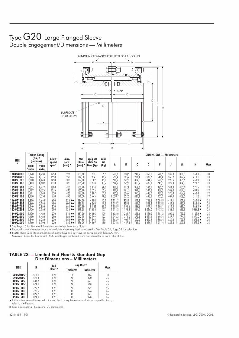
Type G20 Large Flanged SleeveDouble Engagement/Dimensions — Millimeters
42 (M451-110) © Rexnord Industries, LLC, 2004, 2006.
SIZE�
Torque Rating(Nm) †
(millions)AllowSpeedrpm ‡
Max.Bore
(mm) �
MinBore
(mm) �
Cplg WtWith NoBore (kg)
LubeWt
(kg)
DIMENSIONS — Millimeters
A B C D F J M N Gap1000Series
2000Series
1080/2080G 0,170 0,234 1750 266 101,60 703 9,5 590,6 508,5 249,2 355,6 571,5 242,8 300,0 368,3 101090/2090G 0,226 0,315 1550 290 114,30 984 12,2 660,4 565,4 276,4 393,7 641,4 265,2 327,2 419,1 131100/2100G 0,310 0,443 1450 320 127,00 1 302 15,0 711,2 622,3 304,8 444,5 698,5 293,6 355,6 469,9 131110/2110G 0,413 0,609 1330 373 139,70 1 678 17,7 774,7 679,2 333,2 495,3 749,3 322,3 384,0 520,7 13
1120/2120G 0,555 0,777 1200 400 152,40 2 114 20,9 838,2 717,8 352,6 546,1 825,5 341,4 403,4 571,5 131130/2130G 0,719 0,925 1075 440 165,10 2 595 32,7 911,4 761,7 371,3 584,2 886,0 362,0 434,8 609,6 191140/2140G 0,911 1,140 920 460 177,80 3 107 33,1 965,2 806,4 393,2 635,0 939,8 378,0 457,2 660,4 191150/2150G 1,100 1,350 770 490 190,50 3 765 40,8 1 028,7 857,2 419,1 685,8 1003,3 407,9 482,6 711,2 19
1160/2160G 1,310 1,640 650 525 �� 254,00 4 708 43,1 1 111,2 908,0 441,3 736,6 1 085,9 419,1 501,6 762,0 � 251180/2180G 1,660 2,140 480 600 �� 285,75 6 260 49,9 1 219,2 939,8 457,2 838,2 1 193,8 434,8 520,7 863,6 � 251200/2200G 2,140 2,850 370 660 �� 317,50 8 582 68,0 1 358,9 1 098,6 536,6 927,1 1 308,1 514,4 635,0 965,2 � 251220/2220G 2,720 3,560 290 725 �� 349,25 11 685 107 1 511,3 1 193,8 584,2 1 016,0 1 473,2 565,2 685,8 1 066,8 � 25
1240/2240G 3,470 4,480 270 810 �� 381,00 14 606 109 1 632,0 1 282,7 628,6 1 130,3 1 581,2 606,6 723,9 1 168,4 � 251260/2260G 4,490 5,480 250 880 �� 412,75 17 799 122 1 746,2 1 371,6 673,1 1 231,9 1 695,4 647,7 774,7 1 270,0 � 251280/2280G 5,840 6,760 230 950 �� 444,50 21 192 136 1 866,9 1 409,7 692,9 1 333,5 1 803,4 666,8 793,8 1 371,6 � 251300/2300G 6,760 8,190 220 1 025 �� 476,25 24 807 150 1 974,8 1 447,8 711,2 1 435,1 1 911,4 685,8 800,1 1 473,2 � 25
� See Page 15 for General Information and other Reference Notes.� Reduced shank diameter hubs are available where required bore permits. See Table 31, Page 53 for selection.
� Note: There is no standardization of metric keys and keyways for bores greater than 500 mm.Maximum bores for flex hubs 1150G and larger are based on a hub diameter to bore ratio of 1.4.
TABLE 23 — Limited End Float & Standard GapDisc Dimensions – Millimeters
SIZE BEnd
Float �
Gap Disc �
GapThickness Diameter
1080/2080G 517,1 4,78 16 416 181090/2090G 577,3 4,78 22 470 251100/2100G 634,2 4,78 22 521 251110/2110G 691,1 4,78 22 568 25
1120/2120G 729,7 4,78 22 622 251130/2130G 778,5 4,78 33 676 361140/2140G 822,2 4,78 33 727 361150/2150G 874,0 4,78 33 778 36
� If this value exceeds one-half rotor end float or equivalent manufacturer’s specifications,refer to the Factory.
� Gap disc material: Neoprene, 70 durometer.
J J
B
LUBRICATETHRU SLEEVE
GAPCC
M M
MINIMUM CLEARANCE REQUIRED FOR ALIGNING
DF
AN

© Rexnord Industries, LLC, 2004, 2006. (M451-110) 43
SIZE�
TorqueRating(Nm)
(millions) †
AllowSpeedrpm ‡
Max Bore(mm) �
MinBore(mm)�
Cplg WtWith No
Bore(kg)
LubeWt
(kg)
DIMENSIONS — Millimeters
A B C D E F J K � L M N Gap1000Series
2000Series
FlexHub
RigidHub
1080/2080G 0,170 0,234 1750 266 340 101,60 699 5 590,6 511,0 249,4 355,6 8,1 571,5 242,8 450,8 248,9 300,0 368,3 131090/2090G 0,226 0,315 1550 290 380 114,30 984 6 660,4 566,4 276,4 393,7 8,1 641,4 265,2 508,0 275,8 327,2 419,1 141100/2100G 0,310 0,443 1450 320 400 127,00 1 252 8 711,2 625,3 304,8 444,5 9,7 698,5 293,6 530,4 304,8 355,6 469,9 161110/2110G 0,413 0,609 1330 373 440 139,70 1 637 9 774,7 682,2 333,2 495,3 9,7 749,3 322,3 584,2 333,2 384,0 520,7 16
1120/2120G 0,555 0,777 1200 400 483 152,40 2 077 11 838,2 720,6 352,6 546,1 9,7 825,5 341,4 647,7 352,3 403,4 571,5 161130/2130G 0,719 0,925 1075 440 500 � 165,10 2 572 17 911,4 761,7 371,3 584,2 9,7 886,0 362,0 708,2 371,3 434,8 609,6 191140/2140G 0,911 1,140 920 460 535 � 177,80 3 062 17 965,2 805,9 393,2 635,0 9,7 939,8 378,0 749,3 393,7 457,2 660,4 191150/2150G 1,100 1,350 770 490 580 � 190,50 3 751 21 1 028,7 857,2 419,1 685,8 9,7 1 003,3 407,9 812,8 419,1 482,6 711,2 19
1160/2160G 1,310 1,640 650 525�� 630 �� 254,00 4 631 22 1 111,2 908,3 441,3 736,6 12,7 1 085,8 419,1 886,0 � 441,5 501,6 762,0 � 251180/2180G 1,660 2,140 480 600�� 710 �� 285,75 6 069 25 1 219,2 939,8 457,2 838,2 12,7 1 193,8 434,8 993,6 � 457,2 520,7 863,6 � 251200/2200G 2,140 2,850 370 660�� 780 �� 317,50 8 482 34 1 358,9 1 098,6 536,6 927,1 12,7 1 308,1 514,4 1 095,2 � 536,4 635,0 965,2 � 251220/2220G 2,720 3,560 290 725�� 890 �� 349,25 11 680 54 1 511,3 1 196,8 584,2 1 016,0 15,7 1 473,2 565,2 1 244,6 � 584,2 685,8 1 066,8 � 28
1240/2240G 3,470 4,480 270 810�� 940 �� 381,00 14 388 57 1 632,0 1 285,7 628,6 1 130,3 15,7 1 581,2 606,6 1 314,7 � 628,6 723,9 1 168,4 � 281260/2260G 4,490 5,480 250 880�� 1 015 �� 412,75 17 722 61 1 746,2 1 374,6 673,1 1 231,9 15,7 1 695,5 647,7 1 422,4 � 673,1 774,7 1 270,0 � 281280/2280G 5,840 6,760 230 950�� 1 090 �� 444,50 21 110 70 1 866,9 1 412,2 691,9 1 333,5 15,7 1 803,4 666,8 1 530,6 � 691,9 793,8 1 371,6 � 281300/2300G 6,760 8,190 220 1 025�� 1 170 �� 476,25 24 712 77 1 974,8 1 450,8 711,2 1 435,1 15,7 1 911,4 685,8 1 638,3 � 711,2 800,1 1 473,2 � 28
� See Page 15 for General Information and other Reference Notes.� Reduced shank diameter hubs are available where required bore permits. See Table 31, Page 53 for selection.� Dimension K may be an “as cast” surface depending upon coupling size and bore.
� Note: There is no standardization of metric keys and keyways for bores greater than 500 mm.Maximum bores for flex hubs 1150G and rigid hubs 1130G and larger are based on a hub diameter to bore ratio of 1.4.
Type G52 Large Flanged SleeveSingle Engagement/Dimensions — Millimeters
IMPORTANT — When couplings are mounted on a floatingshaft, do not exceed allowable shaft speed for the assembly. Usea gap disc in each coupling.
LUBRICATETHRU SLEEVE
M
MINIMUM CLEARANCE REQUIRED FOR ALIGNING
RIGID HUB
EGAP
L
N
C
FLEXHUB
J
B
KD
A
F
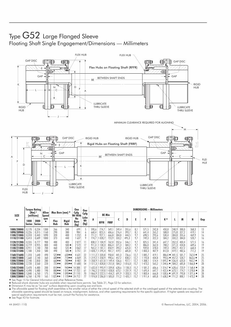
44 (M451-110) © Rexnord Industries, LLC, 2004, 2006.
SIZE
�
Torque Rating(Nm) †
(millions)AllowSpeedrpm
�
Max Bore (mm) �OneCplg
Wt WithNo
Bore(kg)
OneCplg
LubeWt
(kg)
DIMENSIONS – Millimeters
A
BE Min
C D E F J K � L M N Gap1000Series
2000Series
FlexHub
RigidHub
RFFR FRRF
1080/2080G 0,170 0,234 1300 266 340 699 5 590,6 774,7 549,1 249,4 355,6 8,1 571,5 242,8 450,8 248,9 300,0 368,3 131090/2090G 0,226 0,315 1160 290 380 984 6 660,4 825,5 606,6 276,4 393,7 8,1 641,4 265,2 508,0 275,8 327,2 419,1 141100/2100G 0,310 0,443 1090 320 400 1 252 8 711,2 927,1 666,8 304,8 444,5 9,7 698,5 293,6 530,4 304,8 355,6 469,9 161110/2110G 0,413 0,609 1000 373 440 1 637 9 774,7 1 028,7 723,9 333,2 495,3 9,7 749,3 322,3 584,2 333,2 384,0 520,7 16
1120/2120G 0,555 0,777 900 400 483 2 077 11 838,2 1 104,9 762,0 352,6 546,1 9,7 825,5 341,4 647,7 352,3 403,4 571,5 161130/2130G 0,719 0,925 800 440 500 � 2 572 17 911,4 1 130,3 806,4 371,3 584,2 9,7 886,0 362,0 708,2 371,3 434,8 609,6 191140/2140G 0,911 1,140 700 460 535 � 3 062 17 965,2 1 181,1 850,9 393,2 635,0 9,7 939,8 378,0 749,3 393,7 457,2 660,4 191150/2150G 1,100 1,350 580 490 580 � 3 751 21 1 028,7 1 295,4 901,7 419,1 685,8 9,7 1 003,3 407,9 812,8 419,1 482,6 711,2 19
1160/2160G 1,310 1,640 490 525�� 630�� 4 631 22 1 111,2 1 320,8 958,8 441,3 736,6 12,7 1 085,7 419,1 886,0 � 441,5 501,7 762,0 � 251180/2180G 1,660 2,140 360 600�� 710�� 6 069 25 1 219,2 1 358,9 990,6 457,2 838,2 12,7 1 193,8 434,8 993,6 � 457,2 520,7 863,6 � 251200/2200G 2,140 2,850 280 660�� 780�� 8 482 34 1 358,9 1 651,0 1 149,4 536,6 927,1 12,7 1 308,1 514,4 1 095,2 � 536,4 635,0 965,2 � 251220/2220G 2,720 3,560 220 725�� 890�� 11 680 54 1 511,3 1 828,8 1 251,0 584,2 1 016,0 15,7 1 473,2 565,2 1 244,6 � 584,2 685,8 1 066,8 � 28
1240/2240G 3,470 4,480 200 810�� 940�� 14 388 57 1 632,0 1 993,9 1 339,8 628,6 1 130,3 15,7 1 581,2 606,6 1 314,7 � 628,6 723,9 1 168,4 � 281260/2260G 4,490 5,480 190 880�� 1 015�� 17 722 61 1 746,2 2 159,0 1 428,8 673,1 1 231,9 15,7 1 695,4 647,7 1 422,4 � 673,1 774,7 1 270,0 � 281280/2280G 5,840 6,760 175 950�� 1 090�� 21 110 70 1 866,9 2 222,5 1 454,2 691,9 1 333,5 15,7 1 803,4 666,8 1 530,6 � 691,9 793,8 1 371,6 � 281300/2300G 6,760 8,190 165 1 025�� 1 170�� 24 712 77 1 974,8 2 286,0 1 505,0 711,2 1 435,1 15,7 1 911,4 685,8 1 638,3 � 711,2 800,1 1 473,2 � 28
� See Page 15 for General Information and other Reference Notes.� Reduced shank diameter hubs are available when required bore permits. See Table 31, Page 53 for selection.� Dimension K may be as “as cast” surface depending upon coupling size and bore.� The allowable speed for floating shaft assemblies is the smaller value of either the critical speed of the selected shaft or the cataloged speed of the selected size coupling. The
allowable operating speed should be based on torque, misalignment, balance, and other operating requirements for the specific application. If higher speeds are required orspecial application requirements must be met, consult the Factory for assistance.
� See Page 43 for footnote.
KD
F
ABETWEEN SHAFT ENDS
GAP
GAP DISC
J
C
L
LUBRICATETHRU SLEEVE
N
FLEXHUB
FLEXHUB
MINIMUM CLEARANCE REQUIRED FOR ALIGNING
RIGID HUBRIGID HUB
E
GAP
GAP DISC
C
LUBRICATETHRU SLEEVE
M
BE
Rigid Hubs on Floating Shaft (FRRF)
GAP
GAP DISC
K
RIGIDHUB
J
DF
A
FLEX HUB
L
LUBRICATETHRU SLEEVE
BETWEEN SHAFT ENDS
LUBRICATETHRU SLEEVE
RIGIDHUB
FLEX HUB
E
N
GAP
GAP DISC
BE
C
Type G52 Large Flanged SleeveFloating Shaft Single Engagement/Dimensions — Millimeters
Flex Hubs on Floating Shaft (RFFR)
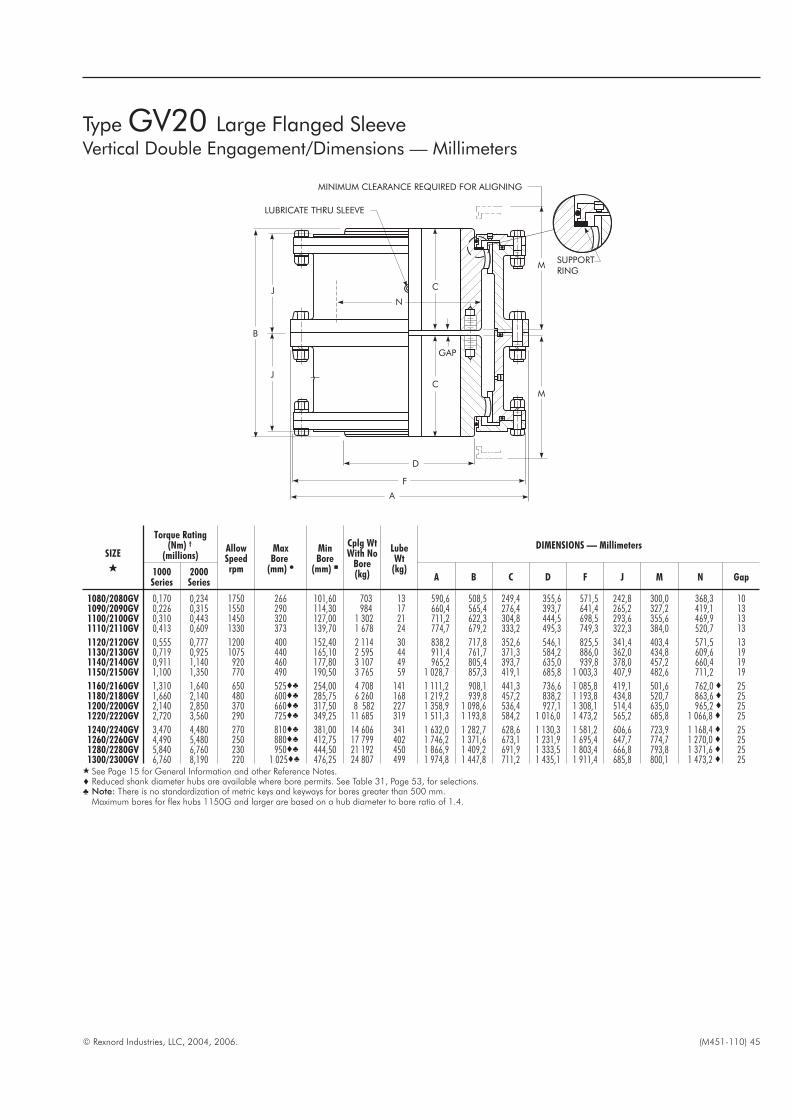
© Rexnord Industries, LLC, 2004, 2006. (M451-110) 45
SIZE
�
Torque Rating(Nm) †
(millions)AllowSpeedrpm
MaxBore
(mm) �
MinBore
(mm) �
Cplg WtWith No
Bore(kg)
LubeWt
(kg)
DIMENSIONS — Millimeters
1000Series
2000Series
A B C D F J M N Gap
1080/2080GV 0,170 0,234 1750 266 101,60 703 13 590,6 508,5 249,4 355,6 571,5 242,8 300,0 368,3 101090/2090GV 0,226 0,315 1550 290 114,30 984 17 660,4 565,4 276,4 393,7 641,4 265,2 327,2 419,1 131100/2100GV 0,310 0,443 1450 320 127,00 1 302 21 711,2 622,3 304,8 444,5 698,5 293,6 355,6 469,9 131110/2110GV 0,413 0,609 1330 373 139,70 1 678 24 774,7 679,2 333,2 495,3 749,3 322,3 384,0 520,7 13
1120/2120GV 0,555 0,777 1200 400 152,40 2 114 30 838,2 717,8 352,6 546,1 825,5 341,4 403,4 571,5 131130/2130GV 0,719 0,925 1075 440 165,10 2 595 44 911,4 761,7 371,3 584,2 886,0 362,0 434,8 609,6 191140/2140GV 0,911 1,140 920 460 177,80 3 107 49 965,2 805,4 393,7 635,0 939,8 378,0 457,2 660,4 191150/2150GV 1,100 1,350 770 490 190,50 3 765 59 1 028,7 857,3 419,1 685,8 1 003,3 407,9 482,6 711,2 19
1160/2160GV 1,310 1,640 650 525�� 254,00 4 708 141 1 111,2 908,1 441,3 736,6 1 085,8 419,1 501,6 762,0 � 251180/2180GV 1,660 2,140 480 600�� 285,75 6 260 168 1 219,2 939,8 457,2 838,2 1 193,8 434,8 520,7 863,6 � 251200/2200GV 2,140 2,850 370 660�� 317,50 8 582 227 1 358,9 1 098,6 536,4 927,1 1 308,1 514,4 635,0 965,2 � 251220/2220GV 2,720 3,560 290 725�� 349,25 11 685 319 1 511,3 1 193,8 584,2 1 016,0 1 473,2 565,2 685,8 1 066,8 � 25
1240/2240GV 3,470 4,480 270 810�� 381,00 14 606 341 1 632,0 1 282,7 628,6 1 130,3 1 581,2 606,6 723,9 1 168,4 � 251260/2260GV 4,490 5,480 250 880�� 412,75 17 799 402 1 746,2 1 371,6 673,1 1 231,9 1 695,4 647,7 774,7 1 270,0 � 251280/2280GV 5,840 6,760 230 950�� 444,50 21 192 450 1 866,9 1 409,2 691,9 1 333,5 1 803,4 666,8 793,8 1 371,6 � 251300/2300GV 6,760 8,190 220 1 025�� 476,25 24 807 499 1 974,8 1 447,8 711,2 1 435,1 1 911,4 685,8 800,1 1 473,2 � 25
� See Page 15 for General Information and other Reference Notes.� Reduced shank diameter hubs are available where bore permits. See Table 31, Page 53, for selections.� Note: There is no standardization of metric keys and keyways for bores greater than 500 mm.
Maximum bores for flex hubs 1150G and larger are based on a hub diameter to bore ratio of 1.4.
Type GV20 Large Flanged SleeveVertical Double Engagement/Dimensions — Millimeters
SUPPORTRING
MINIMUM CLEARANCE REQUIRED FOR ALIGNING
LUBRICATE THRU SLEEVE
N
GAP
C
C
D
M
M
J
J
A
F
B

46 (M451-110) © Rexnord Industries, LLC, 2004, 2006.
SIZE
�
TorqueRating(Nm) †
(millions)AllowSpeedrpm
Max Bore(mm) �
MinBoreBothHubs(mm)�
CplgWt.
WithNo
Bore(kg)
LubeWt
(kg)
DIMENSIONS — Millimeters
1000Series
2000Series
FlexHub
RigidHub
A B C D E F J K � L M N BE CS Gap
1080/2080G 0,170 0,234 1750 266 340 101,60 699 4,99 590,6 511,6 236,7 355,6 8,1 571,5 242,8 450,8 248,9 287,3 368,3 38,6 224,0 261090/2090G 0,226 0,315 1550 290 380 114,30 984 6,35 660,4 567,2 261,9 393,7 8,1 641,4 265,2 508,0 275,8 314,5 419,1 42,2 249,2 291100/2100G 0,310 0,443 1450 320 400 127,00 1252 7,71 711,2 625,3 288,8 444,5 9,7 698,5 293,6 530,4 304,8 339,9 469,9 48,3 273,1 331110/2110G 0,413 0,609 1330 373 440 139,70 1637 9,07 774,7 682,8 317,2 495,3 9,7 749,3 322,3 584,2 333,2 368,3 520,7 48,3 301,5 33
1120/2120G 0,555 0,777 1200 400 483 152,40 2077 10,9 838,2 721,4 336,6 546,1 9,7 825,5 341,4 647,7 352,3 387,4 571,5 48,3 320,8 331130/2130G 0,719 0,925 1075 440 500 � 165,10 2572 16,8 911,4 762,0 352,0 584,2 9,7 886,0 362,0 708,2 371,3 419,1 609,6 54,9 336,3 391140/2140G 0,911 1,140 920 460 535 � 177,80 3062 17,2 965,2 806,4 373,9 635,0 9,7 939,8 378,0 749,3 393,7 441,5 660,4 54,9 358,1 391150/2150G 1,100 1,350 770 490 580 � 190,50 3751 20,9 1 028,7 857,2 399,8 685,8 9,7 1 003,3 407,9 812,8 419,1 466,9 711,2 54,9 384,0 39
1160/2160G 1,310 1,640 650 525�� 630�� 254,00 4631 21,8 1 111,2 908,0 416,1 736,6 12,7 1 085,8 419,1 886,0 � 441,5 482,6 762,0 � 70,4 397,0 511180/2180G 1,660 2,140 480 600�� 710�� 285,75 6069 25,4 1 219,2 939,8 431,8 838,2 12,7 1 193,8 434,8 993,6 � 457,2 501,6 863,6 � 70,4 412,8 511200/2200G 2,140 2,850 370 660�� 780�� 317,50 8482 34,5 1 358,9 1 098,6 511,0 927,1 12,7 1 308,1 514,4 1 095,2 � 536,4 616,0 965,2 � 70,4 492,3 511220/2220G 2,720 3,560 290 725�� 890�� 349,25 11 680 54,4 1 511,3 1 196,8 555,8 1 016,0 15,7 1 473,2 565,2 1 244,6 � 584,2 660,4 1 066,8 � 83,3 530,4 58
1240/2240G 3,470 4,480 270 810�� 940�� 381,00 14 388 56,7 1 632,0 1 285,7 599,9 1 130,3 15,7 1 581,2 606,6 1 314,7 � 628,6 698,5 1 168,4 � 83,3 574,5 581260/2260G 4,490 5,480 250 880�� 1 015�� 412,75 17 722 61,2 1 746,2 1 374,6 644,7 1 231,9 15,7 1 695,4 647,7 1 422,4 � 673,1 749,3 1 270,0 � 83,1 619,3 581280/2280G 5,840 6,760 230 950�� 1 090�� 444,50 21 110 70,3 1 866,9 1 412,7 663,4 1 333,5 15,7 1 803,4 666,8 1 530,6 � 691,9 768,4 1 371,6 � 83,1 638,0 581300/2300G 6,760 8,190 220 1 025�� 1 170�� 476,25 24 712 77,1 1 974,8 1 450,8 682,8 1 435,1 15,7 1 911,4 685,8 1 638,3 � 711,2 774,7 1 473,2 � 83,1 657,4 58
� See Page 15 for General Information and other Reference Notes. Downward load capacity of lower coupling supporting button for Size 1080GV52 and larger is 39 463kilograms.
� Reduced shank diameter hubs are available where required bore permits. See Table 31, Page 53 for selections.� Dimension K may be an “as cast” surface depending upon coupling size and bore.� Note: There is no standardization of metric keys and keyways for bores greater than 500 mm.
Maximum bores for flex hubs 1150G and rigid hubs 1130G and larger are based on a hub diameter to bore ratio of 1.4.
Type GV52 Large Flanged SleeveVertical Single Engagement/Dimensions — Millimeters
GASKET
J
B
LUBRICATETHRU SLEEVE
N
L
BE
SHAFTCENTERINGCOMPONENTS
RIGID HUB
GAP
E
M
MINIMUM CLEARANCEREQUIRED FOR ALIGNING
FLEXHUBF
A
D
CS
K
C
(TOP POSITION ONLY)
IMPORTANT — When couplings are mounted on a floatingshaft, do not exceed allowable shaft speed for the assembly,

© Rexnord Industries, LLC, 2004, 2006. (M451-110) 47
SIZE
�
Torque Rating
(Nm) †
(millions)AllowSpeedrpm †
MaxBore
(mm) �
MinBore(mm)�
Cplg WtWith
No Bore(kg)
LubeWt
(kg)
DIMENSIONS — Millimeters
1000Series
2000Series
AB
MaxC D F J M
T (Max) Gap
Each Total Min Max
1080/2080GL 0,170 0,234 1160 266 101,60 685 9,53 590,6 740,2 249,4 355,6 571,5 242,8 300,0 14,0 27,9 213 2411090/2090GL 0,226 0,315 1030 290 114,30 943 12,2 660,4 793,0 276,4 393,7 641,4 265,2 327,2 22,9 45,7 195 2401100/2100GL 0,310 0,443 960 320 127,00 1 247 15,0 711,2 893,6 304,8 444,5 698,5 293,6 355,6 21,1 42,2 242 284
1110/2110GL 0,413 0,609 880 373 139,70 1 610 17,7 774,7 994,2 333,2 495,3 749,3 322,3 384,0 19,0 38,1 290 3281120/2120GL 0,555 0,777 800 400 152,40 2 037 20,9 838,2 1 061,2 352,6 546,1 825,5 341,4 403,4 19,0 38,1 318 356
� See Page 15 for General Information and Reference Notes.
Type GL20-4 Large Flanged SleeveSlide Double Engagement/Dimensions — Millimeters
M
B
GASKET
J J
DF
A
MCENTERPLATE
MINIMUM CLEARANCE REQUIRED FOR ALIGNING
GAP DISC(BOTH SIDES)
LUBRICATETHRU SLEEVE
CT T
C
GAP

48 (M451-110) © Rexnord Industries, LLC, 2004, 2006.
SIZE�
TorqueRating(Nm)
(millions) †
AllowSpeedrpm ‡
MaxBore
(mm) �
MinBore
(mm) �
Cplg WtWith
No Bore(kg)
DIMENSIONS — Millimeters
B C D M P T V AA AB AC AE ZG Gap
1080G 0,170 110 266 101,60 498 508,0 249,4 368,3 228,6 249,4 108,2 88,4 491,7 461,3 19,3 215,9 41,4 101090G 0,226 100 290 114,30 698 559,3 276,4 419,1 263,7 270,3 130,6 95,0 556,3 515,6 25,4 251,0 52,8 131100G 0,310 90 320 127,00 956 622,3 304,8 469,9 283,0 304,8 137,2 107,7 607,1 566,4 25,4 270,3 52,8 131110G 0,413 80 373 139,70 1 256 679,2 333,2 520,7 296,2 333,2 143,8 114,3 655,3 614,7 25,4 283,5 52,8 13
1120G 0,555 75 400 152,40 1 559 702,6 352,6 571,5 292,1 337,3 149,4 104,6 711,2 670,6 25,4 279,4 52,3 131130G 0,719 70 440 165,10 1 779 697,0 338,8 609,6 288,5 338,8 141,7 102,6 778,3 727,5 31,5 275,8 32,0 191140G 0,911 65 460 177,80 2 127 719,3 350,0 660,4 288,5 350,0 141,7 102,6 828,0 777,2 31,5 275,8 26,9 191150G 1,100 60 490 190,50 2 623 770,1 375,4 711,2 288,5 375,4 141,7 102,6 882,4 831,6 31,5 275,8 21,3 19
� See Page 15 for General Information and Reference Notes.
Type G70Disconnect/Dimensions — Millimeters
M
T
P C
D
AE
B
AB
AA
ACZG
GAP
LUBRICATEGEARTEETHANDSLEEVE PINGROOVEWITHMOLYKOTEBR-2PLUSOREQUIVALENT.
MINIMUMCLEARANCEREQUIREDFORALIGNING
V
Optional hand operated shifter mechanism toshift and secure the proper position of the
sleeve assembly.
DrivingEnd
DrivenEnd
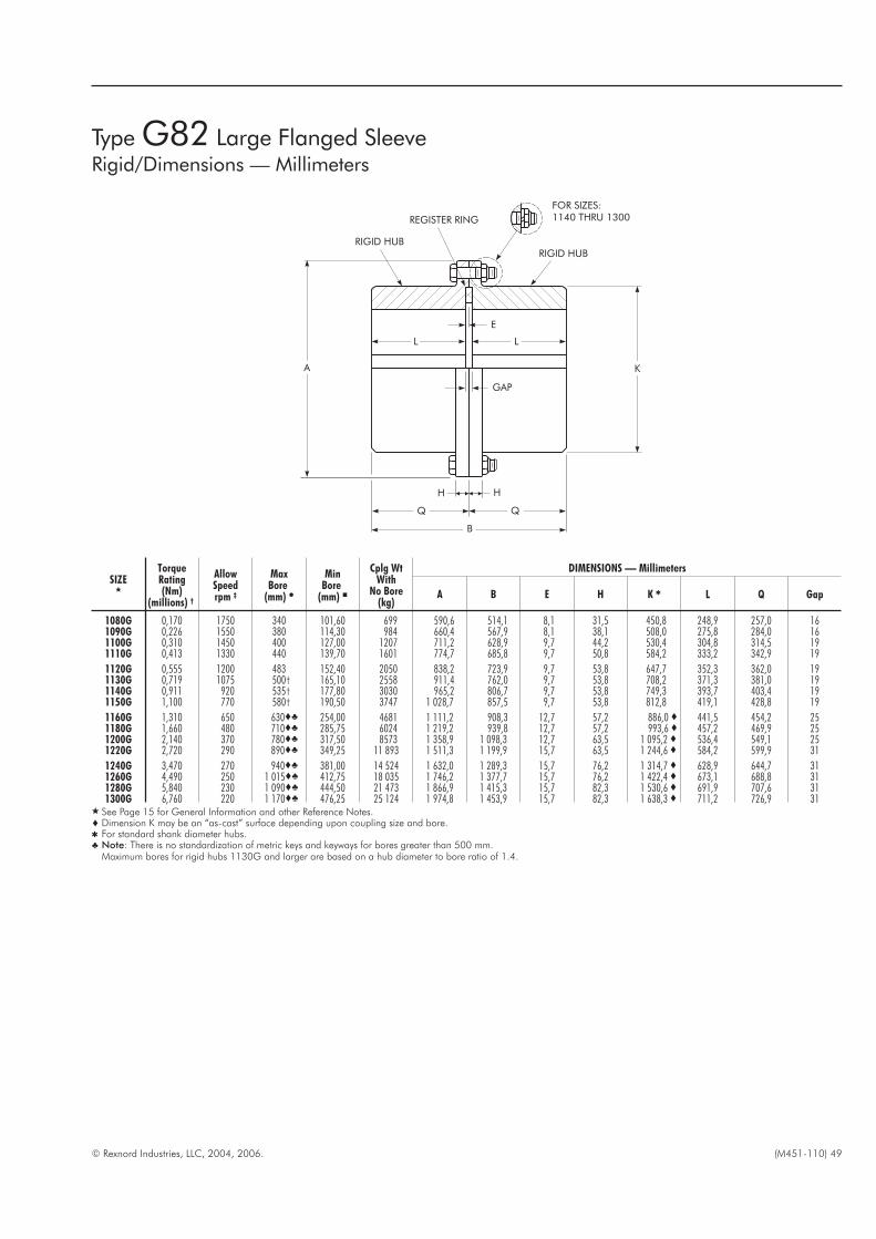
© Rexnord Industries, LLC, 2004, 2006. (M451-110) 49
SIZE�
TorqueRating(Nm)
(millions) †
AllowSpeedrpm ‡
MaxBore
(mm) �
MinBore
(mm) �
Cplg WtWith
No Bore(kg)
DIMENSIONS — Millimeters
A B E H K � L Q Gap
1080G 0,170 1750 340 101,60 699 590,6 514,1 8,1 31,5 450,8 248,9 257,0 161090G 0,226 1550 380 114,30 984 660,4 567,9 8,1 38,1 508,0 275,8 284,0 161100G 0,310 1450 400 127,00 1207 711,2 628,9 9,7 44,2 530,4 304,8 314,5 191110G 0,413 1330 440 139,70 1601 774,7 685,8 9,7 50,8 584,2 333,2 342,9 19
1120G 0,555 1200 483 152,40 2050 838,2 723,9 9,7 53,8 647,7 352,3 362,0 191130G 0,719 1075 500† 165,10 2558 911,4 762,0 9,7 53,8 708,2 371,3 381,0 191140G 0,911 920 535† 177,80 3030 965,2 806,7 9,7 53,8 749,3 393,7 403,4 191150G 1,100 770 580† 190,50 3747 1 028,7 857,5 9,7 53,8 812,8 419,1 428,8 19
1160G 1,310 650 630�� 254,00 4681 1 111,2 908,3 12,7 57,2 886,0 � 441,5 454,2 251180G 1,660 480 710�� 285,75 6024 1 219,2 939,8 12,7 57,2 993,6 � 457,2 469,9 251200G 2,140 370 780�� 317,50 8573 1 358,9 1 098,3 12,7 63,5 1 095,2 � 536,4 549,1 251220G 2,720 290 890�� 349,25 11 893 1 511,3 1 199,9 15,7 63,5 1 244,6 � 584,2 599,9 31
1240G 3,470 270 940�� 381,00 14 524 1 632,0 1 289,3 15,7 76,2 1 314,7 � 628,9 644,7 311260G 4,490 250 1 015�� 412,75 18 035 1 746,2 1 377,7 15,7 76,2 1 422,4 � 673,1 688,8 311280G 5,840 230 1 090�� 444,50 21 473 1 866,9 1 415,3 15,7 82,3 1 530,6 � 691,9 707,6 311300G 6,760 220 1 170�� 476,25 25 124 1 974,8 1 453,9 15,7 82,3 1 638,3 � 711,2 726,9 31
� See Page 15 for General Information and other Reference Notes.� Dimension K may be an “as-cast” surface depending upon coupling size and bore.� For standard shank diameter hubs.� Note: There is no standardization of metric keys and keyways for bores greater than 500 mm.
Maximum bores for rigid hubs 1130G and larger are based on a hub diameter to bore ratio of 1.4.
Type G82 Large Flanged SleeveRigid/Dimensions — Millimeters
HH
Q Q
B
A
GAP
L L
E
FOR SIZES:1140 THRU 1300
RIGID HUB
REGISTER RING
RIGID HUB
K

50 (M451-110) © Rexnord Industries, LLC, 2004, 2006.
SIZE�
1000 Series 2000 SeriesAllowSpeed
rpm ‡
MaxBore
(mm) �
MinBore
(mm) �
Approximate Value — Millimeters
Shear Torque (Nm x 106) Shear Torque (Nm x 106)AA X Gap B
Min Max Min Max
1080/2080GR 0,052 0,235 0,081 0,366 880 266 101,6 990,6 812,8 121 619,81090/2090GR 0,071 0,319 0,107 0,495 780 290 114,3 1 066,8 889,0 127 679,71100/2100GR 0,099 0,449 0,156 0,696 730 320 127,0 1 117,6 939,8 146 755,91110/2110GR 0,137 0,617 0,215 0,960 670 373 139,7 1 168,4 990,6 165 831,6
1120/2120GR 0,176 0,795 0,271 1,22 600 400 152,4 1 244,6 1 066,8 178 882,91130/2130GR 0,216 0,983 0,327 1,47 540 440 165,1 1 346,2 1 143,0 184 927,11140/2140GR 0,258 1,16 0,403 1,82 460 460 177,8 1 409,7 1 193,8 197 984,51150/2150GR 0,299 1,34 0,460 2,07 390 490 190,5 1 485,9 1 257,3 203 1 041,4
1160/2160GR 0,384 1,71 0,571 2,57 330 525 � 254,0 1 600,2 1 346,2 229 1 111,51180/2180GR 0,498 2,23 0,747 3,35 240 600 � 285,8 1 651,0 1 447,8 241 1 155,71200/2200GR 0,647 3,02 1,00 4,47 190 660 � 317,5 1 803,4 1 600,2 261 1 333,51220/2220GR 0,847 3,80 1,25 5,59 150 725 � 349,2 1 930,4 1 727,2 273 1 441,7
1240/2240GR 1,05 4,69 1,57 7,04 140 810 � 381,0 2 057,4 1 854,2 305 1 562,11260/2260GR 1,29 5,81 1,92 8,60 130 880� 412,8 2 184,4 1 981,2 324 1 670,31280/2280GR 1,54 6,93 2,37 10,62 120 950 � 444,5 2 311,4 2 108,2 337 1 721,11300/2300GR 1,87 8,38 2,87 12,85 110 1 025 � 476,2 2 413,0 2 209,8 362 1 784,6
� See Page 15 for General Information and Reference Notes.� Note: There is no standardization of metric keys and keyways for bores greater than 500 mm.
Maximum bores for flex hubs 1150G and larger are based on a hub diameter to bore ratio of 1.4.
Type GR20 Large Flanged SleeveShear Pin Double Engagement/Dimensions — Millimeters
GAP
B
XAA
PIN REMOVAL
SHEAR PINREMOVAL PLATE

© Rexnord Industries, LLC, 2004, 2006. (M451-110) 51
TABLE 25 — Recommended Bore Tolerances Rexnord Steel Coupling Hubs – Millimeters
Shaft Diameter (ISO/R775-1969) Bore Diameter Tolerance
Nominal Tolerance Clearance Transitional Interference
6 to 30 j6/k6 � F7 H7 M6
Over 30 to 50 k6 F7 H7 K6
Over 50 to 80 m6 F7 H7 K7
Over 80 to 100 m6 F7 H7 M7
Over 100 to 200 m6 F7 H7 P7
Over 200 to 355 m6 F7 H7 R7
Over 355 to 500 m6 F7 H7 R8
� Per DIN 748 — Differs with ISO/R775.
H
W
T2R
T = D + T2
TD
Check Key Stresses
Engineering Data — Large Flanged Sleeve
TABLE 24 — Recommended Commercial Keys for Bores with OneKey — Millimeters (Per ISO R773 Standard)
Shaft DiameterKey Size
Over Thru
95 110 28 x 16110 130 32 x 18130 150 36 x 20150 170 40 x 22
170 200 45 x 25200 230 50 x 28230 260 56 x 32260 290 63 x 32
290 330 70 x 36330 380 80 x 40380 440 90 x 45440 500 100 x 50
� Note: For metric recommended keys of shafts above 500 mm, consult the Factory.

52 (M451-110) © Rexnord Industries, LLC, 2004, 2006.
TABLE 27 — Sleeve JackScrew Holes
SIZE B.C. (mm) Tap Size (in)
1080/2080G 527,0 .875-9 UNC1090/2090G 590,6 1.000-8 UNC1100/2100G 641,4 1.000-8 UNC1110/2110G 698,5 1.000-8 UNC
1120/2120G 762,0 1.125-7 UNC1130/2130G 822,3 1.250-7 UNC1140/2140G 876,3 1.250-7 UNC1150/2150G 933,4 1.250-7 UNC
1160/2160G 1 009,6 1.250-7 UNC1180/2180G 1 117,6 1.250-7 UNC1200/2200G 1 231,9 1.500-6 UNC1220/2220G 1 384,3 1.500-6 UNC
1240/2240G 1 479,6 1.500-6 UNC1260/2260G 1 593,8 1.500-6 UNC1280/2280G 1 701,8 1.500-6 UNC1300/2300G 1 809,8 1.500-6 UNC
TABLE 26 — Flange Details — Millimeters
SIZE A B C E DD F G H
J BoltsNo. Dia x Lgth(Per Flange )
(Inch)
K BoltsNo. Dia x Lgth
(Inch)T
1080/2080G 590,6 527,05 441,33 7,9 6,4 571,5 527,05 31,8 16- .875 x 3.25 16- 1.125 x 4.125 441,271090/2090G 660,4 590,55 495,30 7,9 6,4 641,4 590,55 38,1 18- 1.000 x 3.50 18- 1.250 x 4.75 495,251100/2100G 711,2 641,35 546,10 9,7 7,9 698,5 641,35 44,4 18- 1.000 x 3.50 18- 1.250 x 5.25 546,051110/2110G 774,7 698,50 596,90 9,7 7,9 749,3 698,50 50,8 18- 1.000 x 3.50 18- 1.500 x 6.00 596,85
1120/2120G 838,2 762,00 654,05 9,7 7,9 825,5 762,00 53,8 18- 1.125 x 3.50 18- 1.500 x 6.25 654,001130/2130G 911,4 822,33 708,03 9.7 7,9 886,0 822,33 53,8 18- 1.250 x 4.50 18- 1.500 x 6.25 707,971140/2140G 965,2 876,30 758,83 9,7 7,9 939,8 876,30 53,8 18- 1.250 x 4.50 18- 1.750 x 6.50 758,771150/2150G 1 028,7 933,45 815,98 9,7 7,9 1 003,3 933,45 53,8 20- 1.250 x 4.50 20- 1.750 x 6.50 815,92
1160/2160G 1 111,2 1 009,65 863,60 12,7 9,7 1 085,9 1 009,65 57,2 20- 1.250 x 4.50 20- 2.000 x 7.00 863,501180/2180G 1 219,2 1 117,60 984,25 12,7 9,7 1 193,8 1 117,60 57,2 22- 1.250 x 4.50 22- 2.000 x 7.00 984,151200/2200G 1 358,9 1 231,90 1 085,85 12.7 9,7 1 308,1 1 231,90 63,5 22- 1.500 x 5.00 22- 2.250 x 7.75 1 085,751220/2220G 1 511,3 1 384,30 1 212,85 15.7 12,7 1 473,2 1 384,30 63,5 24- 1.500 x 5.00 24- 2.250 x 7.75 1 212,75
1240/2240G 1 632,0 1 479,55 1 289,05 15,7 12,7 1 581,2 1 479,55 76,2 22- 1.500 x 5.00 22- 2.750 x 9.75 1 288,951260/2260G 1 746,2 1 593,85 1 390,65 15,7 12,7 1 695,5 1 593,85 76,2 24- 1.500 x 5.00 24- 2.750 x 9.75 1 390,551280/2280G 1 866,9 1 701,80 1 492,25 15,7 12,7 1 803,4 1 701,80 82,6 22- 1.500 x 5.00 22- 3.000 x 10.50 1 492,151300/2300G 1 974,8 1 809,75 1 593,85 15,7 12,7 1 911,4 1 809,75 82,6 24- 1.500 x 5.00 24- 3.000 x 10.50 1 593,75
F
B
J - BOLTS
ENDPLATEFLANGE
K - BOLTS CENTERFLANGE
DD E
T
C
A
G
H
TABLE 30 — WR2 Values – KgM2
WR2 values are based on hubs withno bore.
SIZEType G20
Double EngagementType G52
Single Engagement
1080/2080G 22,2 21,21090/2090G 39,9 38,01100/2100G 61,7 55,51110/2110G 93,3 86,5
1120/2120G 138 1301130/2130G 198 1891140/2140G 269 2561150/2150G 365 351
1160/2160G 526 5141180/2180G 850 8291200/2200G 1 455 1 4251220/2220G 2 475 2 413
1240/2240G 3 565 3 4921260/2260G 4 887 4 8831280/2280G 6 636 6 6941300/2300G 8 742 8 807
TABLE 29 — Torsional Stiffness – Nm/Radian (106)
SIZE
Half Coupling Complete Coupling
FlexHalf
Rigid Half
Type G20
Type G52
LargeShank
MediumShank
SmallShank
LargeShank
MediumShank
SmallShank
1080/2080G 510,7 1 412,4 . . . . . . 255,4 375,1 . . . . . .
1090/2090G 696,0 2 056,4 . . . . . . 348,0 519,8 . . . . . .1100/2100G 881,3 2 248,5 . . . . . . 440,7 632,7 . . . . . .1110/2110G 1 068,9 3 028,1 . . . . . . 534,4 790,9 . . . . . .
1120/2120G 1 423,7 4 304,9 . . . . . . 711,8 1 070,0 . . . . . .1130/2130G 1 794,3 5 785,1 . . . . . . 897,1 1 367,2 . . . . . .1140/2140G 2 119,7 6 835,9 . . . . . . 1 059,9 1 615,8 . . . . . .1150/2150G 2 508,2 8 802,0 . . . . . . 1 254,2 1 954,7 . . . . . .
1160/2160G 3 457,5 12 078,7 7 412,2 2 994,2 1 728,8 2 689,2 2 361,5 1 604,51180/2180G 5 265,4 18 315,8 10 937,5 4 700,4 2 632,7 4 101,6 3 559,2 2 485,81200/2200G 5 988,5 23 004,9 13 705,8 6 022,4 2 994,2 4 745,6 4 158,1 3 005,51220/2220G 10 824,5 34 857,6 17 875,1 8 146,6 5 412,2 8 259,6 6 745,5 4 643,9
1240/2240G 10 508,1 40 789,6 23 106,6 10 496,8 5 254,1 8 350,0 7 220,1 5 254,11260/2260G 13 197,3 51 862,6 28 993,4 13 581,5 6 598,6 10 519,4 9 073,1 6 700,31280/2280G 17 377,9 67 737,8 37 422,5 18 055,9 8 689,0 13 830,0 11 864,0 8 858,51300/2300G 22 146,1 86 155,3 47 139,6 23 264,7 11 073,1 17 615,2 15 072,9 11 344,2
B.C.
B.C.
TABLE 28 — Flex Hub Puller BoltHoles for StandardShank DiameterHubs
SIZE � B.C. (mm) Tap Size – UNC (in)
1080/2080G 317,5 1.000-8 x 1.181090/2090G 355,6 1.250-7 x 1.501100/2100G 393,7 1.500-6 x 1.751110/2110G 444,5 1.500-6 x 1.75
1120/2120G 495,3 1.500-6 x 1.751130/2130G 533,4 1.500-6 x 1.751140/2140G 584,2 1.500-6 x 1.751150/2150G 635,0 1.500-6 x 1.75
1160/2160G 685,8 1.500-6 x 1.751180/2180G 774,7 1.500-6 x 1.751200/2200G 863,6 2.000-4.5 x 2.381220/2220G 952,5 2.000-4.5 x 2.38
1240/2240G 1 041,4 2.000-4.5 x 2.381260/2260G 1 143,0 2.000-4.5 x 2.381280/2280G 1 244,6 2.000-4.5 x 2.381300/2300G 1 346,2 2.000-4.5 x 2.38
� Refer to Table 32 for flex hub puller data on reducedshank diameter hubs, Sizes 1160/2160 thru 1300/2300.
Engineering Data — Large Flanged Sleeve

© Rexnord Industries, LLC, 2004, 2006. (M451-110) 53
B.C.N or K
TABLE 32 — Flex Hub Puller Bolt Holes for Reduced Shank Diameter Hubs — Millimeters
SIZE�
Millimeters SIZE�
Millimeters
N B.C. Tap Size (in) N B.C. Tap Size (in)
1160/2160G647,7 571,5
1.500-6 UNC 1240/2240G1 054,1 927,1 2-4.5 UNC
527,0 450,8 863,6 749,3
1180/2180G749,3 660,4
1.500-6 UNC 1260/2260G1 155,7 1 028,7
2-4.5 UNC609,6 520,7 946,1 819,2
1200/2200G850,9 749,3
2-4.5 UNC 1280/2280G1 257,3 1 130,3
2-4.5 UNC692,2 590,6 1 035,0 908,0
1220/2220G 952,5 838,2 2-4.5 UNC 1300/2300G 1 358,9 1 231,9 2-4.5 UNC781,1 666,8 1 117,6 990,6
Data for couplings with reduced shank diameter hubs.Depending upon bore, a reduced shank diameter hub (Dimension “N”or “K”) is available for each coupling, sizes 1160/2160 thru1300/2300. This provides reduced weight and WR2.
TABLE 31 — Bore Ranges for Reduced Shank Diameter Hubs — Millimeters �
SIZE�
Flex Hub Weight (kg)
CouplingWR2
(Kgm2)
Rigid Hub
K �
Weight (kg) �
CouplingWR2
(Kgm2)MaxBore� �
MinBore
N �
SleevesEnd Rings
andFasteners
Flex HubWith No
Bore (Each)
MaxBore� �
MinBore
SleeveEnd Ring
andFasteners
Flex HubWith No
Bore(Each)
Rigid HubWith No
Bore(Each)
1160/2160G463 330 647,7 1388 1388 470 562 375 787,4 748 1388 1901 418376 254 527,0 1388 1193 437 426 254 596,9 . . . 1193 1383 338
1180/2180G535 381 749,3 1642 1878 767 626 419 876,3 885 1878 2413 671435 286 609,6 1642 1601 702 481 286 673,1 . . . 1601 1787 543
1200/2200G608 432 850,9 2200 2749 1315 689 470 965,2 1184 2749 3434 1152494 318 692,2 2200 2291 1169 535 318 749,3 . .. 2291 2549 922
1220/2220G680 489 952,5 3257 3706 2275 753 515 1054,1 1724 3706 4468 1910558 349 781,0 3257 3093 2033 590 350 825,5 . . . 3093 3361 1545
1240/2240G753 540 1054,1 3633 4826 3252 816 565 1143,0 1978 4826 5693 2808617 381 863,6 3633 3978 2848 644 381 901,7 . . . 3978 4264 2234
1260/2260G826 591 1155,7 3978 6142 4454 880 610 1231,9 2164 6142 7013 3890676 413 946,2 3978 5008 4588 699 413 977,9 . . . 5008 5298 3038
1280/2280G898 650 1257,3 4627 7412 6081 943 660 1320,8 2517 7412 8319 5288739 445 1035,0 4627 6055 5147 753 445 1054,1 . . . 6055 6382 4142
1300/2300G 971 700 1358,9 5185 8845 8035 1007 705 1409,7 2817 8845 9671 6961798 476 1117,6 5185 7199 6742 807 476 1130,3 . . . 7199 7466 5435
� See Page 15 for General Information and other reference notes.� Hubs with the least possible ‘K” or “N” dimensions for the required bore are normally furnished.� Total weight of coupling varies with “K” or “N” dimensions of rigid and flex hub selection. Add weight of selected hubs to “Sleeve, End Ring and Fasteners” weight.� Note: Maximum bore dimensions are based upon a N/1.4 or K/1.4 ratio. For key and keyway dimensions, consult the Factory.
Engineering Data — Large Flanged Sleeve

54 (M451-110) © Rexnord Industries, LLC, 2004, 2006.
Engineering Data — Large Flanged Sleeve
TABLE 33 — Standard Filleted Keyways & Chamfered Keys — Millimeters
Nominal Bore Key Hub Keyway
Over ThruSize
(Nominal)45° ChamferSuggested
Width Depth � Fillet Radii
95 110 28 x 16 0,70 28 +/–0,0260 6,4 / 6,6 0,60110 130 32 x 18 0,70 32 +/–0,0260 7,4 / 7,6 0,60130 150 36 x 20 1 10 36 +/–0,0260 8,4 / 8,7 1.00150 170 40 x 22 1,10 40 +/–0,0260 9,4 / 9,7 1,00
170 200 45 x 25 1,10 45 +/–0,0260 10,4 / 10,7 1,00200 230 50 x 28 1,10 50 +/–0,0260 11,4 / 11,7 1,00230 260 56 x 32 1,80 56 +/–0,0260 12,4 / 12,7 1,60260 290 63 x 32 1,80 63 +/–0,0260 12,4 / 12,7 1,60
290 330 70 x 36 1,80 70 +/–0,0260 14,4 / 14/7 1,60330 380 80 x 40 2,70 80 +/–0,0260 15.4 / 15,7 2,50380 440 90 x 45 2,70 90 +/–0,0260 17,4 / 17,7 2,50440 500 100 x 50 2,70 100 +/–0,0260 19,5 / 19,8 2,50
� Shallow keyway depth must equal or exceed 2/3 of the full keyway depth of the square keys shown above.
Standard Filleted Keyways & Chamfered Keys
Fillets are standard in metric keyways. If fillets are requiredin inch keyways, refer to the Factory for recommendations. H
W
T2R
T = D + T2
TD

© Rexnord Industries, LLC, 2004, 2006. (M451-110) 55
TABLE 34 — Misalignment & End Float – Double Engagement Couplings
SIZE
Angular Misalignment Limits Parallel Misalignment Limits End Float
Installation Operating � Static � Installation Operating � Static �
StdFDMin
(mm)
NormalGap
+/–10%(mm)
PhysicalLimitMin
(2) FD+Gap(mm)
A Minus B(mm)
DegreesPer
Mesh
A Minus B(mm)
DegreesPer
Mesh
A Minus B(mm)
DegreesPer
Mesh
P(mm)
DegreesPer
Mesh
P(mm)
DegreesPer
Mesh
P(mm)
DegreesPer
Mesh
1080/2080 0,81 1/16° 4,83 3/8° 9,65 3/4° 0,41 1/16° 2,46 3/8° 4,90 3/4° 4,32 10 181090/2090 0,91 1/16° 5,49 3/8° 10,97 3/4° 0,43 1/16° 2,64 3/8° 5,23 3/4° 6,30 13 251100/2100 1,02 1/16° 6,15 3/8° 12,29 3/4° 0,48 1/16° 2,97 3/8° 5,94 3/4° 6,30 13 251110/2110 1,14 1/16° 6,81 3/8° 13,64 3/4° 0,56 1/16° 3,30 3/8° 6,58 3/4° 6,30 13 25
1120/2120 1,24 1/16° 7,49 3/8° 14,99 3/4° 0,58 1/16° 3,51 3/8° 7,04 3/4° 6,30 13 251130/2130 1,32 1/16° 7,98 3/8° 15,95 3/4° 0,61 1/16° 3,61 3/8° 7,24 3/4° 8,76 19 371140/2140 1,45 1/16° 8,64 3/8° 17,30 3/4° 0,64 1/16° 3,81 3/8° 7,59 3/4° 8,76 19 371150/2150 1,55 1/16° 9,32 3/8° 18,62 3/4° 0,69 1/16° 4,17 3/8° 8,33 3/4° 8,76 19 37
1160/2160 1,60 1/16° 9,65 3/8° 19,28 3/4° 0,71 1/16° 4,22 3/8° 8,41 3/4° 11,68 25 491180/2180 1,83 1/16° 10,97 3/8° 21,95 3/4° 0,74 1/16° 4,37 3/8° 8,74 3/4° 11,68 25 491200/2200 2,03 1/16° 12,14 3/8° 24,28 3/4° 0,89 1/16° 5,28 3/8° 10,57 3/4° 11,68 25 491220/2220 2,21 1/16° 13,31 3/8° 26,59 3/4° 0,99 1/16° 5,87 3/8° 11,73 3/4° 11,68 25 49
1240/2240 2,46 1/16° 14,78 3/8° 29,59 3/4° 1,07 1/16° 6,40 3/8° 12,80 3/4° 11,68 25 491260/2260 2,69 1/16° 16,13 3/8° 32,46 3/4° 1,17 1/16° 6,93 3/8° 13,89 3/4° 11,68 25 491280/2280 2,92 1/16° 17,45 3/8° 34,90 3/4° 1,19 1/16° 7,14 3/8° 14,30 3/4° 11,68 25 491300/2300 3,12 1/16° 18,80 3/8° 37,57 3/4° 1,22 1/16° 7,37 3/8° 14,71 3/4° 11,68 25 49
� These maximum operating alignment limits are each based on 3/8° per flex half coupling. Combined values of parallel and angular misalignment should not exceed 3/8°. TypeGL slide couplings are limited to 1/4° per flex half. Application requirements in excess of these values should be referred to the the Factory for review.
Engineering Data — Large Flanged Sleeve
TABLE 35 — Misalignment & End Float – Single EngagementCouplings
SIZE
Angular Misalignment Limits �
End FloatInstallation Operating Static
A Minus B(mm)
DegreesPer
Mesh
A Minus B(mm)
DegreesPer
Mesh
A Minus B(mm)
DegreesPer
Mesh
StdFD Min
(mm)
NormalShaftGap(mm)
NormalFace
Gap (X)(mm)
PhysicalLimit MinFD + Gap
(mm)
1080/2080 0,81 1/8 ° 2,41 3/8° 4,83 3/4° 4,57 13 5 171090/2090 0,91 1/8 ° 2,74 3/8° 5,49 3/4° 6,55 14 6 211100/2100 1,02 1/8 ° 3,07 3/8° 6,15 3/4° 6,48 16 6 221110/2110 1,14 1/8 ° 3,40 3/8° 6,81 3/4° 6,48 16 6 22
1120/2120 1,24 1/8 ° 3,73 3/8° 7,49 3/4° 6,48 16 6 221130/2130 1,32 1/8 ° 3,99 3/8° 7,98 3/4° 8,64 19 9 281140/2140 1,45 1/8 ° 4,32 3/8° 8,64 3/4° 8,64 19 9 281150/2150 1,55 1/8 ° 4,65 3/8° 9,32 3/4° 8,64 19 9 28
1160/2160 1,60 1/8 ° 4,83 3/8° 9,65 3/4° 11,43 25 13 371180/2180 1,83 1/8 ° 5,49 3/8° 10,97 3/4° 11,43 25 13 371200/2200 2,03 1/8 ° 6,07 3/8° 12,14 3/4° 11,43 25 13 371220/2220 2,21 1/8 ° 6,65 3/8° 13,31 3/4° 11,43 29 13 40
1240/2240 2,46 1/8 ° 7,39 3/8° 14,78 3/4° 11,43 29 13 401260/2260 2,69 1/8 ° 8,05 3/8° 16,13 3/4° 11,43 29 13 401280/2280 2,92 1/8 ° 8,74 3/8° 17,45 3/4° 11,30 29 13 401300/2300 3,12 1/8 ° 9,40 3/8° 18,80 3/4° 11,30 29 13 40
� Do not use single engagement couplings to compensate for parallel offset misalignment.
GAP
B
A
A MINUS B
ANGULAR
END FLOAT
FD FD
FDFDGAP
GAP
PARALLEL
P
END FLOAT
FD
FD
GAP
Double Engagement Couplings
GAP
A
B
A MINUS B
ANGULAR
Single Engagement Couplings
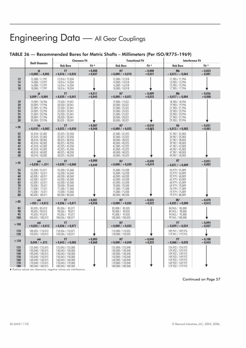
56 (M451-110) © Rexnord Industries, LLC, 2004, 2006.
TABLE 36 — Recommended Bores for Metric Shafts – Millimeters (Per ISO/R775–1969)
Shaft DiameterClearance Fit Transitional Fit Interference Fit
Hub Bore Fit � Hub Bore Fit � Hub Bore Fit �
j6+0,008 / – 0,003
F7+0,016 / +0,034
+0,008+0,037
H7+0,000 / +0,018
– 0,008+0,021
M6– 0,015 / – 0,064
– 0,023– 0,001
12 12,008 / 11,997 12,016 / 12,034 12,000 / 12,018 11,985 / 11,99614 14,008 / 13,997 14,016 / 14,034 14,000 / 14,018 13,985 / 13,99616 16,008 / 15,997 16,016 / 16,034 16,000 / 16,018 15,985 / 15,99618 18,008 / 17,997 18,016 / 18,034 18,000 / 18,018 17,985 / 17,996
j60,009 / – 0,004
F7+0,020 / +0,041
+0,011+0,045
H7+0,000 / +0,021
– 0,009+0,025
M6– 0,017 / – 0,004
– 0,026+0,000
19 19,009 / 18,996 19,020 / 19,041 19,000 / 19,021 18,983 / 18,99620 20,009 / 19,996 20,020 / 20,041 20,000 / 20,021 19,983 / 19,99622 22,009 / 21,996 22,020 / 22,041 22,000 / 22,021 21,983 / 21,99624 24,009 / 23,996 24,020 / 24,041 24,000 / 24,021 23,983 / 23,99625 25,009 / 24,996 25,020 / 25,041 25,000 / 25,021 24,983 / 24,99628 28,009 / 27,996 28,020 / 28,041 28,000 / 28,021 27,983 / 27,99630 30,008 / 29,996 30,020 / 30,041 30,000 / 30,021 29,983 / 29,996
>30k6
+0,018 / +0,002F7
+0,025 / +0,050+0,007+0,048
H7+0,000 / +0,025
– 0,018+0,023
K6– 0,013 / +0,003
– 0,031+0,001
32 32,018 / 32,002 32,025 / 32,050 32,000 / 32,025 31,987 / 32,00335 35,018 / 35,002 32,025 / 32,050 35,000 / 35,025 34,987 / 35,00338 38,018 / 38,002 38,025 / 38,050 38,000 / 38,025 37,987 / 38,00340 40,018 / 40,002 40,025 / 40,050 40,000 / 40,025 39,987 / 40,00342 42,018 / 42,002 42,025 / 42,050 42,000 / 42,025 41,987 / 42,00345 45,018 / 45,002 45,025 / 45,050 45,000 / 45,025 44,987 / 45,00348 48,018 / 48,002 48,025 / 48,050 48,000 / 48,025 47,987 / 48,00350 50,018 / 50,002 50,025 / 50,050 50,000 / 50,025 49,987 / 50,003
>50m6
+0,030 / +,011F7
+0,030 / +0,060+0,000
+0,049H7
+0,000 / +0,030– 0,030+0,019
K7
– 0,021 / +0,009– 0,051– 0,002
55 55,030 / 55,011 55,030 / 55,060 55,000 / 55,030 54,979 / 55,00956 56,030 / 56,011 56,030 / 56,060 56,000 / 56,030 55,979 / 56,00960 60,030 / 60,011 60,030 / 60,060 60,000 / 60,030 59,979 / 60,00963 63,030 / 63,011 63,030 / 63,060 63,000 / 63,030 62,979 / 63,00965 65,030 / 65,011 65,030 / 65,060 65,000 / 65,030 64,979 / 65,00970 70,030 / 70,011 70,030 / 70,060 70,000 / 70,030 69,979 / 70,00971 71,030 / 71,011 71,030 / 71,060 71,000 / 71,030 70,799 / 71,00975 75,030 / 75,011 75,030 / 75,060 75,000 / 75,030 74,979 / 75,00980 80,030 / 80,011 80,030 / 80,060 80,000 / 80,030 79,979 / 80,009
>80m6
+035 / +0,013F7
+0,036 / +0,071+0,001+0,058
H7+0,000 / +0,035
– 0,035+0,022
M7– 0,035 / +0,000
– 0,070– 0,013
85 85,035 / 85,013 85,036 / 85,071 85,000 / 85,035 84,965 / 85,00090 90,035 / 90,013 90,036 / 90,071 90,000 / 90,035 89,965 / 90,00095 95,035 / 95,013 95,036 / 95,071 95,000 / 95,035 94,965 / 95,000
100 100,035 / 100,013 100,036 / 100,071 100,000 / 100,035 99,965 / 100,000
>100m6
+0,035 / +0,013F7
+0,036 / +0,071H7
+0,000 / +0,035P7
– 0,059 / – 0,024– 0,094– 0,037
110 100,035 / 110,013 110,036 / 110,071 110,000 / 110,035 109,941 / 109,976120 120,035 / 120,013 120,036 / 120,071 120,000 / 120,035 119,941 / 119,976
>120m6
0,040 / +,015F7
+0,043 / +0,083+0,003+0,068
H7+0,000 / +0,040
– 0,040+0,025
P7– 0,068 / – 0,028
– 0,108– 0,043
125 125,040 / 125,015 125,043 / 125,083 125,000 / 125,040 124,932 / 124,972130 130,040 / 130,015 130,043 / 130,083 130,000 / 130,040 129,932 / 129,972140 140,040 / 140,015 140,043 / 140,083 140,000 / 140,040 139,932 / 139,972150 150,040 / 150,015 150,043 / 150,083 150,000 / 150,040 149,932 / 149,972160 160,040 / 160,015 160,043 / 160,083 160,000 / 160,040 159,932 / 159,972170 170,040 / 170,015 170,043 / 170,083 170,000 / 170,040 169,932 / 169,972180 180,040 / 180,015 180,043 / 180,083 180,000 / 180,040 179,932 / 179,972
� Positive values are clearance, negative values are interference.
Engineering Data — All Gear Couplings
Continued on Page 57
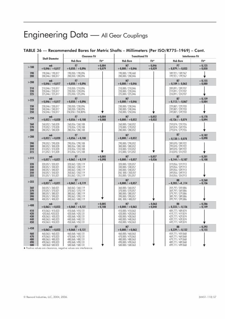
© Rexnord Industries, LLC, 2004, 2006. (M451-110) 57
Engineering Data — All Gear Couplings
TABLE 36 — Recommended Bores for Metric Shafts – Millimeters (Per ISO/R775–1969) – Cont.
Shaft DiameterClearance Fit Transitional Fit Interference Fit
Hub Bore Fit� Hub Bore Fit� Hub Bore Fit�
>180m6
+0,046 / +0,017F7
+0,050 / +0,096+0,004+0,079
H7+0,000 / +0,046
– 0,046+0,029
P7– 0,079 / – 0,033
– 0,125– 0,050
190 190,046 / 190,017 190,050 / 190,096 190,000 / 190,460 189,921 / 189,967200 200,046 / 200,017 200,050 / 200,096 200,000 / 200,046 199,921 / 199,967
>200m6
+0,046 / +0,017F7
+0,050 / +0,096H7
+0,000 / +0,046R7
– 0,109 /– 0,063– 0,155– 0,080
210 210,046 / 210,017 210,050 / 210,096 210,000 / 210,046 209,891 / 209,937220 220,046 / 220,017 220,050 / 220,096 220,000 / 220,046 219,891 / 219,937225 225,046 / 225,017 225,050 / 225,096 225,000 / 225,046 224,891 / 224,937
>225m6
+0,046 / +0,017F7
+0,050 / +0,096H7
+0,000 / +0,046R7
– 0,113 / – 0,067– 0,159– 0,084
230 230,046 / 230,017 230,050 / 230,096 230,000 / 230,046 229,887 / 229,933240 240,046 / 240,017 240,050 / 240,096 240,000 / 240,046 239,887 / 239,933250 250,046 / 250,017 250,050 / 250,8096 250,000 / 250,046 249,887 / 249,933
>250m6
+0,052 / +0,020F7
+0,056 / +0,108+0,004+0,088
H7+0,000 / +0,052
– 0,052+0,032
R7–0,126 / – 0,074
– 0,178– 0,094
260 260,052 / 260,020 260,056 / 260,108 260,000 / 260,052 259,874 / 259,926270 270,052 / 270,020 270,056 / 270,108 270,000 / 270,052 269,874 / 269,926280 280,052 / 280,020 280,056 / 280,108 280,000 / 280,052 279,874 / 279,926
>280m6
+0,052 / +0,020F7
+0,056 / +0,108H7
+0,000 / +0,052R7
– 0,130 /– 0,078– 0,182– 0,098
290 290,052 / 290,020 290,056 / 290,108 290,000 / 290,052 289,870 / 289,922300 300,052 / 300,020 300,056 / 300,108 300,000 / 300,052 299,870 / 299,922310 310,052 / 310,020 310,056 / 310,108 310,000 / 310,052 309,870 / 309,922315 315,052 / 315,020 315,056 / 315,108 315,000 / 315,052 314,870 / 314,922
>315m6
+0,057 / +0,021F7
+0,062 / +0,119+0,005+0,098
H7+0,000 / +0,057
– 0,057+0,036
R7– 0,144 / – 0,187
– 0,201– 0,108
320 320,057 / 320,021 320,062 / 320,119 320,000 / 320,057 319,856 / 319,913330 330,057 / 330,021 330,062 / 330,119 330,000 / 330,057 329,856 / 329,913340 340,057 / 340,021 340,062 / 340,119 340,000 / 340,057 339,856 / 339,913350 350,057 / 350,021 350,062 / 350,119 350, 000 / 350,057 349,856 / 349,913355 355,057 / 355,021 355,062 / 355,119 355,000 / 355,057 354,856 / 354,913
>355m6
+0,057 / +0,021F7
+0,062 / +0,119H7
+0,000 / +0,057R8
– 0,203 / –0 ,114– 0,260– 0,136
360 360,057 / 360,021 360,062 / 360,119 360,000 / 360,057 359,797 / 359,886370 370,057 / 370,021 370,062 / 370,119 370,000 / 370,057 369,797 / 369,886380 380,057 / 380,021 380,062 / 380,119 380,000 / 380,057 379,797 / 379,886390 390,057 / 390,021 390,062 / 390,119 390,000 / 390,057 389,797 / 389,886400 400,057 / 400,021 400,062 / 400,119 400, 000 / 400,057 399,797 / 399,886
>400m6
+0,063 / +0,023F7
+0,068 / +0,131+0,005+0,108
H7+0,000 / +0,063
– 0,063+0,040
R8– 0,223 / – 0,126
– 0,286– 0,149
410 410,063 / 410,023 410,068 / 410,131 410,000 / 410,063 409,777 / 409,874420 420,063 /420,023 420,068 / 420,131 420,000 / 420,063 419,777 / 419,874430 430,063 / 430,023 430,068 / 430,131 430,000 / 430,063 429,777 / 429,874440 440,063 / 440,023 440,068 / 440,131 440,000 / 440,063 439,777 / 439,874450 450,063 / 450,023 450,068 / 450,131 450,000 / 450,063 449,777 / 449,874
>450m6
+0,063 / +0,023F7
+0,068 / +0,131H7
+0,000 / +0,063R8
– 0,229 / – 0,132– 0,292– 0,155
460 460,063 / 460,023 460,068 / 460,131 460,000 / 460,063 459,771 / 459,868470 470,063 / 470,023 470,068 / 470,131 470,000 / 470,063 469,771 / 469,868480 480,063 / 480,023 480,068 / 480,131 480,000 / 480,063 479,771 / 479,868490 490,063 / 490,023 490,068 / 490,131 490,000 / 490,063 489,771 / 489,868500 500,063/ 500,023 500,068 / 500,131 500,000 / 500,063 499,771 / 499,868
� Positive values are clearance, negative values are interference.
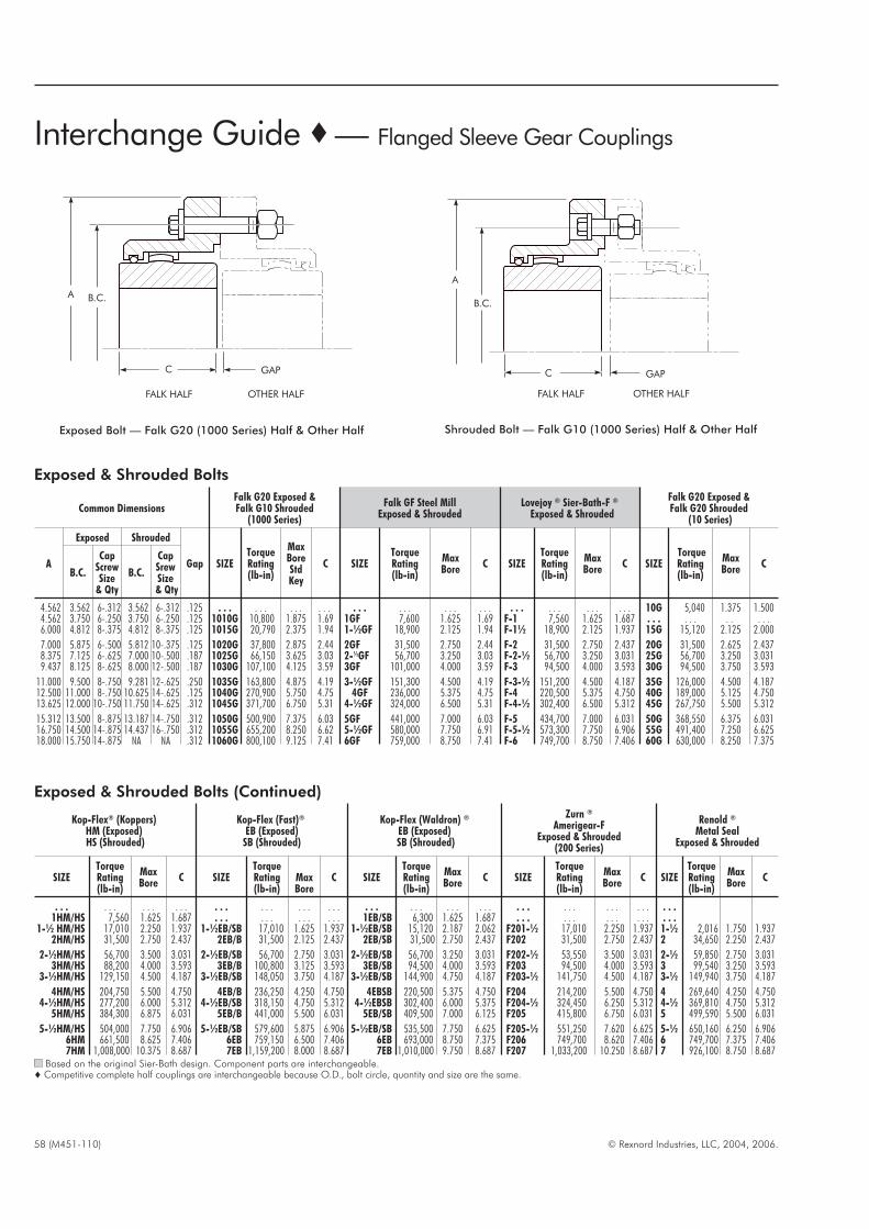
58 (M451-110) © Rexnord Industries, LLC, 2004, 2006.
Exposed & Shrouded Bolts (Continued)
Kop-Flex® (Koppers)HM (Exposed)HS (Shrouded)
Kop-Flex (Fast)®
EB (Exposed)SB (Shrouded)
Kop-Flex (Waldron) ®
EB (Exposed)SB (Shrouded)
Zurn ®
Amerigear-FExposed & Shrouded
(200 Series)
Renold ®
Metal SealExposed & Shrouded
SIZETorqueRating(lb-in)
MaxBore
C SIZETorqueRating(lb-in)
MaxBore
C SIZETorqueRating(lb-in)
MaxBore
C SIZETorqueRating(lb-in)
MaxBore
C SIZETorqueRating(lb-in)
MaxBore
C
. . . . . . . . . . . . . . . . . . . . . . . . . . . . . . . . . . . . . . . . . . . . . . . . . . .1HM/HS 7,560 1.625 1.687 . . . . . . . . . . . . 1EB/SB 6,300 1.625 1.687 . . . . . . . . . . . . . . .
1-½ HM/HS 17,010 2.250 1.937 1-½EB/SB 17,010 1.625 1.937 1-½EB/SB 15,120 2.187 2.062 F201-½ 17,010 2.250 1.937 1-½ 2,016 1.750 1.9372HM/HS 31,500 2.750 2.437 2EB/B 31,500 2.125 2.437 2EB/SB 31,500 2.750 2.437 F202 31,500 2.750 2.437 2 34,650 2.250 2.437
2-½HM/HS 56,700 3.500 3.031 2-½EB/SB 56,700 2.750 3.031 2-½EB/SB 56,700 3.250 3.031 F202-½ 53,550 3.500 3.031 2-½ 59,850 2.750 3.0313HM/HS 88,200 4.000 3.593 3EB/B 100,800 3.125 3.593 3EB/SB 94,500 4.000 3.593 F203 94,500 4.000 3.593 3 99,540 3.250 3.593
3-½HM/HS 129,150 4.500 4.187 3-½EB/SB 148,050 3.750 4.187 3-½EB/SB 144,900 4.750 4.187 F203-½ 141,750 4.500 4.187 3-½ 149,940 3.750 4.187
4HM/HS 204,750 5.500 4.750 4EB/B 236,250 4.250 4.750 4EBSB 220,500 5.375 4.750 F204 214,200 5.500 4.750 4 269,640 4.250 4.7504-½HM/HS 277,200 6.000 5.312 4-½EB/SB 318,150 4.750 5.312 4-½EBSB 302,400 6.000 5.375 F204-½ 324,450 6.250 5.312 4-½ 369,810 4.750 5.312
5HM/HS 384,300 6.875 6.031 5EB/B 441,000 5.500 6.031 5EB/SB 409,500 7.000 6.125 F205 415,800 6.750 6.031 5 499,590 5.500 6.031
5-½HM/HS 504,000 7.750 6.906 5-½EB/SB 579,600 5.875 6.906 5-½EB/SB 535,500 7.750 6.625 F205-½ 551,250 7.620 6.625 5-½ 650,160 6.250 6.9066HM 661,500 8.625 7.406 6EB 759,150 6.500 7.406 6EB 693,000 8.750 7.375 F206 749,700 8.620 7.406 6 749,700 7.375 7.4067HM 1,008,000 10.375 8.687 7EB 1,159,200 8.000 8.687 7EB 1,010,000 9.750 8.687 F207 1,033,200 10.250 8.687 7 926,100 8.750 8.687
Based on the original Sier-Bath design. Component parts are interchangeable.� Competitive complete half couplings are interchangeable because O.D., bolt circle, quantity and size are the same.
Exposed & Shrouded Bolts
Common DimensionsFalk G20 Exposed &Falk G10 Shrouded
(1000 Series)
Falk GF Steel MillExposed & Shrouded
Lovejoy ® Sier-Bath-F ®
Exposed & Shrouded
Falk G20 Exposed &Falk G20 Shrouded
(10 Series)
A
Exposed Shrouded
Gap SIZETorqueRating(lb-in)
MaxBoreStdKey
C SIZETorqueRating(lb-in)
MaxBore
C SIZETorqueRating(lb-in)
MaxBore
C SIZETorqueRating(lb-in)
MaxBore
CB.C.
CapScrewSize
& Qty
B.C.
CapSrewSize& Qty
4.562 3.562 6-.312 3.562 6-.312 .125 . . . . . . . . . . . . . . . . . . . . . . . . . . . . . . . . . . . . 10G 5,040 1.375 1.5004.562 3.750 6-.250 3.750 6-.250 .125 1010G 10,800 1.875 1.69 1GF 7,600 1.625 1.69 F-1 7,560 1.625 1.687 . . . . . . . . . . .6.000 4.812 8-.375 4.812 8-.375 .125 1015G 20,790 2.375 1.94 1-½GF 18,900 2.125 1.94 F-1½ 18,900 2.125 1.937 15G 15,120 2.125 2.000
7.000 5.875 6-.500 5.812 10-.375 .125 1020G 37,800 2.875 2.44 2GF 31,500 2.750 2.44 F-2 31,500 2.750 2.437 20G 31,500 2.625 2.4378.375 7.125 6-.625 7.000 10-.500 .187 1025G 66,150 3.625 3.03 2-½GF 56,700 3.250 3.03 F-2-½ 56,700 3.250 3.031 25G 56,700 3.250 3.0319.437 8.125 8-.625 8.000 12-.500 .187 1030G 107,100 4.125 3.59 3GF 101,000 4.000 3.59 F-3 94,500 4.000 3.593 30G 94,500 3.750 3.593
11.000 9.500 8-.750 9.281 12-.625 .250 1035G 163,800 4.875 4.19 3-½GF 151,300 4.500 4.19 F-3-½ 151,200 4.500 4.187 35G 126,000 4.500 4.18712.500 11.000 8-.750 10.625 14-.625 .125 1040G 270,900 5.750 4.75 4GF 236,000 5.375 4.75 F-4 220,500 5.375 4.750 40G 189,000 5.125 4.75013.625 12.000 10-.750 11.750 14-.625 .312 1045G 371,700 6.750 5.31 4-½GF 324,000 6.500 5.31 F-4-½ 302,400 6.500 5.312 45G 267,750 5.500 5.312
15.312 13.500 8-.875 13.187 14-.750 .312 1050G 500,900 7.375 6.03 5GF 441,000 7.000 6.03 F-5 434,700 7.000 6.031 50G 368,550 6.375 6.03116.750 14.500 14-.875 14.437 16-.750 .312 1055G 655,200 8.250 6.62 5-½GF 580,000 7.750 6.91 F-5-½ 573,300 7.750 6.906 55G 491,400 7.250 6.62518.000 15.750 14-.875 NA NA .312 1060G 800,100 9.125 7.41 6GF 759,000 8.750 7.41 F-6 749,700 8.750 7.406 60G 630,000 8.250 7.375
Interchange Guide �— Flanged Sleeve Gear Couplings
A B.C.
C GAP
FALK HALF OTHER HALF
Exposed Bolt — Falk G20 (1000 Series) Half & Other Half Shrouded Bolt — Falk G10 (1000 Series) Half & Other Half
A
B.C.
C GAP
FALK HALF OTHER HALF
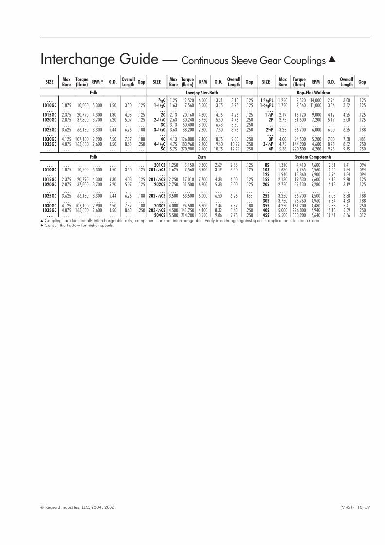
© Rexnord Industries, LLC, 2004, 2006. (M451-110) 59
SIZEMaxBore
Torque(lb-in)
RPM � O.D.OverallLength
Gap SIZEMaxBore
Torque(lb-in)
RPM O.D.OverallLength
Gap SIZEMaxBore
Torque(lb-in)
RPM O.D.OverallLength
Gap
Falk Lovejoy Sier-Bath Kop-Flex Waldron
. . . . . . . . . . . . . . . . . . . . . 7/8C 1.25 2,520 6.000 3.31 3.13 .125 1-1/8PL 1.250 2,520 14,000 2.94 3.00 .1251010GC 1.875 10,800 5,300 3.50 3.50 .125 1-1/2C 1.63 7,560 5,000 3.75 3.75 .125 1-5/8PL 1.750 7,560 11,000 3.56 3.62 .125
. . . . . . . . . . . . . . . . . . . . . . . . . . . . . . . . . . . . . . . . . . . . . . . . . . . . . . . . . . . . . . .1015GC 2.375 20,790 4,300 4.30 4.08 .125 2C 2.13 20,160 4,200 4.75 4.25 .125 1½P 2.19 15,120 9,000 4.12 4.25 .1251020GC 2.875 37,800 3,700 5.20 5.07 .125 2-1/2C 2.63 30,240 3,750 5.50 4.75 .250 2P 2.75 31,500 7,200 5.19 5.00 .125
. . . . . . . . . . . . . . . . . . . . . 3C 3.13 50,400 3,000 6.63 5.50 .250 . . . . . . . . . . . . . . . . . . . . .1025GC 3.625 66,150 3,300 6.44 6.25 .188 3-1/2C 3.63 88,200 2,800 7.50 8.75 .250 2½P 3.25 56,700 6,000 6.00 6.25 .188
. . . . . . . . . . . . . . . . . . . . . . . . . . . . . . . . . . . . . . . . . . . . . . . . . . . . . . . . . . . . . . .1030GC 4.125 107,100 2,900 7.50 7.37 .188 4C 4.13 126,000 2,400 8.75 9.00 .250 3P 4.00 94,500 5,200 7.00 7.38 .1881035GC 4.875 163,800 2,600 8.50 8.63 .250 4-1/2C 4.75 183,960 2,200 9.50 10.25 .250 3-½P 4.75 144,900 4,600 8.25 8.62 .250
. . . . . . . . . . . . . . . . . . . . . 5C 5.75 270,900 2,100 10.75 12.25 .250 4P 5.38 220,500 4,200 9.25 9.75 .250
Falk Zurn System Components
. . . . . . . . . . . . . . . . . . . . . 201CS 1.250 3,150 9,800 2.69 2.88 .125 8S 1.310 4,410 9,600 2.81 1.41 .0941010GC 1.875 10,800 5,300 3.50 3.50 .125 201-¼CS 1.625 7,560 8,900 3.19 3.50 .125 10S 1.630 9,765 7,560 3.44 1.84 .094
. . . . . . . . . . . . . . . . . . . . . . . . . . . . . . . . . . . . . . . 12S 1.940 13,860 6,900 3.94 1.84 .0941015GC 2.375 20,790 4,300 4.30 4.08 .125 201-½CS 2.250 17,010 7,700 4.38 4.00 .125 15S 2.130 19,530 6,600 4.13 2.78 .1251020GC 2.875 37,800 3,700 5.20 5.07 .125 202CS 2.750 31,500 6,200 5.38 5.00 .125 20S 2.750 32,130 5,280 5.13 3.19 .125
. . . . . . . . . . . . . . . . . . . . . . . . . . . . . . . . . . . . . . . . . . . . . . . . . . . . . . . . . . . .1025GC 3.625 66,150 3,300 6.44 6.25 .188 202-½CS 3.500 53,500 6,000 6.50 6.25 188 25S 3.250 56,700 4,500 6.03 3.88 .188
. . . . . . . . . . . . . . . . . . . . . . . . . . . . . . . . . . . . . . . . 30S 3.750 95,760 3,960 6.84 4.53 .1881030GC 4.125 107,100 2,900 7.50 7.37 .188 203CS 4.000 94,500 5,200 7.44 7.37 .188 35S 4.250 151,200 3,480 7.88 5.41 .2501035GC 4.875 163,800 2,600 8.50 8.63 .250 203-½CS 4.500 141,750 4,400 8.32 8.63 .250 40S 5.000 226,800 2,940 9.13 5.59 .250
. . . . . . . . . . . . . . . . . . 204CS 5.500 214,200 3,550 9.86 9.75 .250 45S 5.500 333,900 2,640 10.41 6.66 .312� Couplings are functionally interchangeable only; components are not interchangeable. Verify interchange against specific application selection criteria.� Consult the Factory for higher speeds.
Interchange Guide — Continuous Sleeve Gear Couplings �
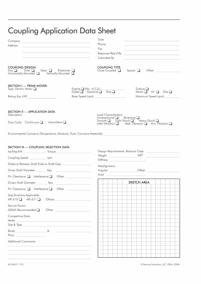
Company
Address
60 (M451-110) © Rexnord Industries, LLC, 2004, 2006.
SKETCH AREA
COUPLING DESIGN:Disc � Grid � Gear � Elastomer �Horizontally Mounted � Vertically Mounted �
COUPLING TYPE:Close Coupled � Spacer � Other
SECTION II — APPLICATION DATADescription
Duty Cycle: Continuous � Intermittent �
Load Characteristics:Unidirectional � Reversing �Smooth � Light Shock � Heavy Shock �Little Vibration � Med. Vibration � Hvy. Vibration �
Environmental Concerns (Temperature, Moisture, Dust, Corrosive Materials)
SECTION III — COUPLING SELECTION DATA
hp/bhp/kW Torque
Coupling Speed rpm
Distance Between Shaft Ends or Shaft Gap
Driver Shaft Diameter Key
Fit: Clearance � Interference � Other
Driven Shaft Diameter Key
Fit: Clearance � Interference � Other
Specifications Applicable:
API-610 � API-671 � Others
Service Factor:
AGMA Recommended � Other
Competitive Data:
Make
Size & Type
Bores &
Price
Additional Comments:
Design Requirements: Balance Class
Weight WR2
Stiffness
Misalignment:
Angular Offset
Axial
Date
Phone
Fax
Response Req’d By
Submitted By
SECTION I — PRIME MOVER:Type: Electric Motor �
Rating (hp, kW)
Engine � (No. of Cyl.)Diesel � Gasoline � Gas �
Base Speed (rpm)
Turbine �Steam � Air � Gas �
Maximum Speed (rpm)
Coupling Application Data Sheet

THIS PAGE INTENTIONALLY LEFT BLANK
For more than 100 years, the dedicated people of Rexnord
have delivered excellence in quality and service to our
customers around the globe. Rexnord is a trusted name when
it comes to providing skillfully engineered products that
improve productivity and efficiency for industrial applications
worldwide. We are committed to exceeding customer
expectations in every area of our business: product design,
application engineering, operations, and customer service.
Because of our customer focus, we are able to thoroughly
understand the needs of your business and have the resources
available to work closely with you to reduce maintenance
costs, eliminate redundant inventories and prevent equipment
down time.
Rexnord represents the most comprehensive portfolio of power
transmission and conveying components in the world with the
brands you know and trust.
World Class Customer Service
AUSTRALIARexnord Australia Pty. Ltd.
Picton, New South Wales
Phone: 61-2-4677-3811
Fax: 61-2-4677-3812
BRAZILRexnord Correntes Ltda.
Sao Leopoldo - RS
Phone: 55-51-579-8022
Fax: 55-51-579-8029
CANADARexnord Canada Ltd.
Scarborough, Ontario
Phone: 1-416-297-6868
Fax: 1-416-297-6873
CHINARexnord China
Shanghai, China
Phone: 86-21-62701942
Fax: 86-21-62701943
EUROPERexnord NV/SA
Mechelen, Belgium
Phone: 32-15-.443811
Fax: 32-15-443860
Rexnord Kette GmbH
Betzdorf, Germany
Phone: 49-2741-2840
Fax: 49-2741-284-385
LATIN AMERICARexnord International, Inc.
Milwaukee, Wisconsin
Phone: 1-414-643-2366
Fax: 1-414-643-3222
E-mail: [email protected]
MEXICORexnord S.A. de C.V.
Queretaro, Qro.
Phone: 52-442-218.5000
Fax: 52-.442-218-1090
SINGAPORERexnord International, Inc.
Singapore City, Singapore
Phone: 65-6338-5622
Fax: 65-6338-5422
UNITED STATESCustomer Service
Phone: 1-866-REXNORD
(1-866-739-6673)
Fax: 1-614-675-1898
E-mail: rexnordcs(state)@rexnord.com
Example: [email protected]
ALL COUNTRIES NOT LISTEDRexnord International
Milwaukee, Wisconsin
Phone: 1-414-643-2366
Fax: 1-414-643-3222
E-mail: [email protected]
WORLDWIDE CUSTOMER SERVICE
M451-110 10/2006 Delzer Litho Printed in USARexnord Industries, LLC, Coupling Group, 5555 South Moorland Road, New Berlin, WI 53151-7953 USA
Phone: 262-796-4060 Fax: 262-796-4064
© 2007 Rexnord Industries LLC
Lifelign and Rexnord are registered trademarks of Rexnord Industries, LLC. Falk is a trademark of
Rexnord. All rights reserved.


