Fall 2006 Advisors Client Dr. John Lamont Iowa State University Professor Ralph Patterson III Department of Electrical and Computer Engineering Primary Vehicle Team Secondary Vehicle Team 2 nd Semester 1 st Semester 1st Semester Tim Gruwell (Team Leader) Brian Baumhover Patrick Turner Andrew Larson Bai Shen Byung Kang Erica Moyer Bill Hughes Maria-Cristina Olivas Hassan Javed Jeff Pries (ME) Josh Robinson Pankaj Makhija Brett Pfeffer (ME) Kito Berg-Taylor (AerE) Gustav Brandstrom (ME) Interdisciplinary Members Interdisciplinary Members Micro-CART U N M A N N E D A E R I A L V E H I C L E ONGO – 03 Microprocessor–Controlled Aerial Robotics Team
Transcript
Fall 2006
Advisors Client Dr. John Lamont Iowa State University Professor Ralph Patterson III Department of Electrical and Computer Engineering
Primary Vehicle Team Secondary Vehicle Team
2nd Semester 1st Semester 1st Semester Tim Gruwell (Team Leader) Brian Baumhover Patrick Turner
Andrew Larson Bai Shen Byung Kang
Erica Moyer Bill Hughes
Maria-Cristina Olivas Hassan Javed Jeff Pries (ME)
Josh Robinson Pankaj Makhija Brett Pfeffer (ME)
Kito Berg-Taylor (AerE)
Gustav Brandstrom (ME)
Interdisciplinary Members
Interdisciplinary Members
Micro-CART U N M A N N E D
A E R I A L
V E H I C L EONGO – 03 Microprocessor–Controlled Aerial Robotics Team
Attitude The orientation of an aircraft's axes relative to a reference line or plane, such as the horizon
AUVSI Association for Unmanned Vehicle Systems International CAD Computer Aided DesignGPS Global positioning systemGSS Ground station systemIARC International Aerial Robotics CompetitionIMU Inertial measurement unitPC-104 x86-based controllable board PIC Programmable interface controllerPID Proportional Integral DerivativePitch Revolution of a vehicle forward and backward on a central axisPro/E Professional Engineer CAD packagePWM Pulse width modulationRC Remote controlRoll Revolution around the longitudinal axis of a vehicleSV Secondary VehicleUAV Unmanned aerial vehicleWIKI (What I Know Is) A public documentation repositoryYaw Revolution around the vertical axis of a vehicle
Acronym Definitions
Fall 2006
Acknowledgement
Iowa State University’s Microprocessor-Controlled Aerial Robotics Team would like to give special thanks to the following people and organizations for their assistance:
Dr. John W Lamont and Assistant Professor Ralph Patterson III for sharing their professional experience and guidance throughout the course of this project.
Lockheed Martin Corporation for their technical expertise and generous financial contribution to this costly endeavor. Without their assistance this project would not be possible.
The Department of Electrical and Computer Engineering for creating Micro-CART and providing the skills and knowledge required for this project.
Fall 2006
Problem Statement
• General Problem Statement– To provide an entry into the International Aerial Robotics
Competition (IARC) Summer 2007 for Iowa State University
• General Solution Approach– Develop an aerial vehicle to compete in IARC Level 1– Develop a secondary vehicle for higher level IARC– Main system components
• PC-104 embedded system • IMU• GPS unit • Battery power supply• Sonar array• Digital magnetic compass• Wireless modem
Fall 2006
IARC (International Aerial Robotics Competition)• Diverse indoor/outdoor environments• Obstacles defined by the competition mission
• Temperature threshold (60o-100o F)• Possible wind, light precipitation, adverse topography of the
competition location• No extreme environments, e.g. fog, rain, etc.
Operating Environment
Fall 2006
Initial Users• Spring 2007 Micro-CART team members
– Responsible for operating vehicle in summer 2007 IARC
Future Users• Future Micro-CART teams• Researchers• Industry representatives• Hobbyists
Intended Users
Fall 2006
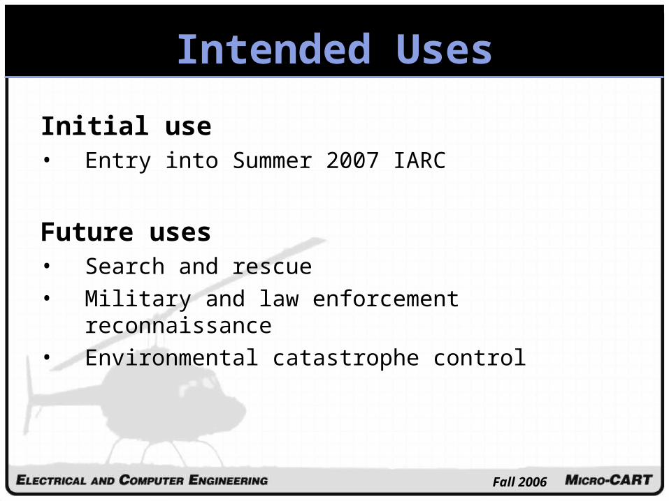
Initial use• Entry into Summer 2007 IARC
Future uses• Search and rescue• Military and law enforcement reconnaissance• Environmental catastrophe control
Intended Uses
Fall 2006
Assumptions • IARC Mission rules may change • Necessary funding remains available • Suitable hardware and software is available at an
affordable price• Onboard computing systems will be sufficient• Current vehicle able to carry necessary equipment• On-board memory sufficient• Sensor system will provide all necessary flight software
inputs• Attachment of secondary vehicle to primary vehicle
Assumptions and Limitations
Fall 2006
Limitations • Physical limits of helicopter• Obstacle detection and avoidance• Power consumption limits• Competition maximum weight limit• Competition requirements• Team member expertise• Weather
Assumptions and Limitations
Fall 2006
Primary VehicleIARC Level 1 Autonomous Functionality• Take off• Navigate to five waypoints with the fifth located three
kilometers away• Maintain a stable hover at the fifth waypoint
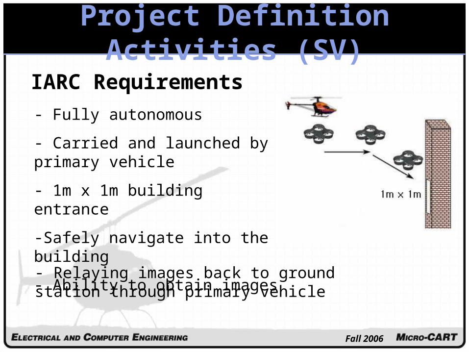
Secondary VehicleHigher level IARC Functionality• Communication with Primary Vehicle• Image Recognition• Obstacle Avoidance
Previous Accomplishments• Acquired helicopter, system components, and sensors• Flight test stand modifications
Present Accomplishments• First autonomously hovering flight on Sept. 26th, 2006• Sonar developed and successfully implemented• New Lithium Polymer battery purchased• Testing procedures and Pre-Flight systems check list
created
Fall 2006
Previous AccomplishmentsFall 1999• Purchased RC helicopter• Purchased Dell PC
Fall 2000 – 2003• Pilot training program
Spring 2002• Acquired security box
Fall 2002• Acquired and setup Linux PC• Sonar circuit design• Complete PIC programming for serial interfacing
Fall 2002 – Spring 2003• Hardware acquisitions• Serial software development• PIC programming• PC-104+ operating system
Spring 2003• Power system• Mounting platform• Manual override switch
Fall 2004
• Replace PC-104+
• Purchased Dell PC
Spring 2005
• Acquired Wireless Data-link
• Acquired Magnetic Compass
Fall 2005
• WIKI
• Hardware enclosure
• New head block
• Flight test stand modifications
• Flight testing
• Onboard payload limitations
Spring 2006
• Untested altitude flight control code
• Flight simulator software ported to Linux
• Flight test stand modifications
• Developed exhaust shield
• GPS research and replacement
Fall 2006
Present Accomplishments
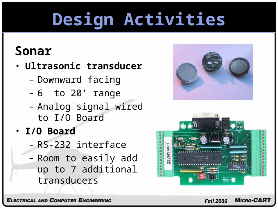
• Sonar
– A/D RS232 Module
– MINI-A Transducer
• New Lithium Polymer Battery
– Much higher Power-to-Weight Ratio
• New flight control software• First autonomously hovering flight on Sept. 26th,
2006• Testing procedures and Pre-Flight systems check
list created
Fall 2006
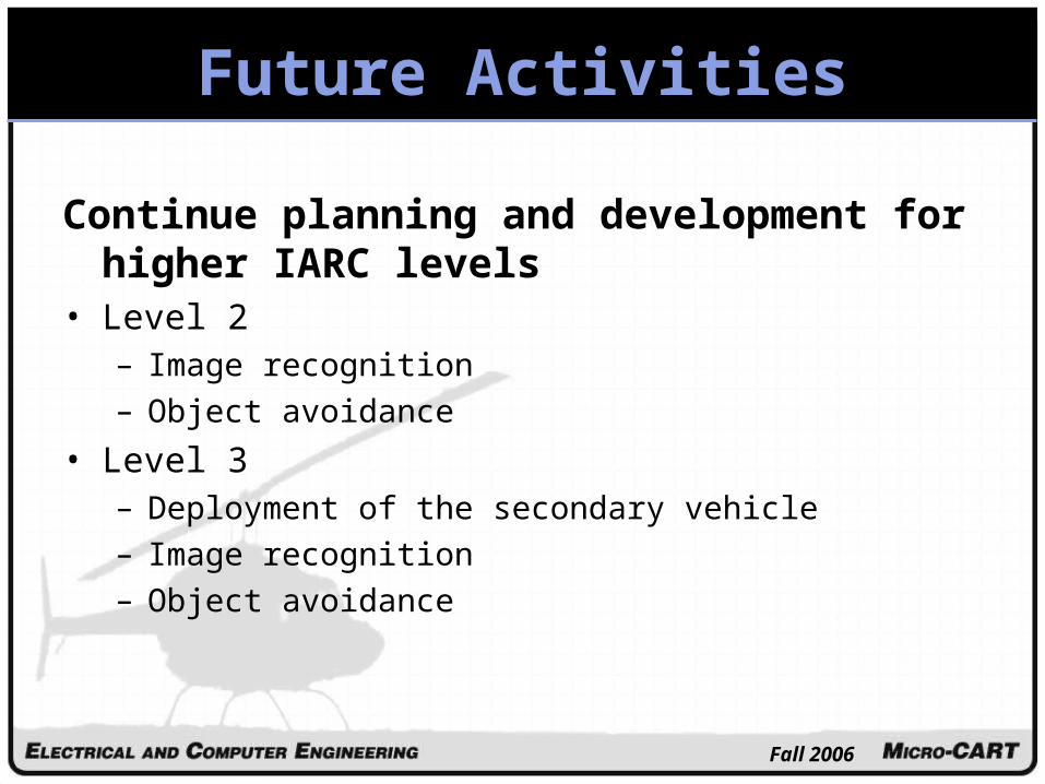
Future Activities
Compete in level one IARC• Complete flight control code• Test fully autonomous flight • Research and plan trip to the competition
Fall 2006
Future Activities
Continue planning and development for higher IARC levels
• At this time, the project will not be commercialized– Too large, too fragile for military applications– Too expensive for civilian applications
• Future– Military– Reconnaissance and surveying– Hazardous site clean-up– Search and rescue– Traffic control and enforcement
Fall 2006
Recommendations
• Continue as originally envisioned– Automated helicopter is close to flying– Project will no longer suffer “memory loss”– Micro-CART is a worthwhile learning
experience
Fall 2006
Lessons Learned
• Take care when testing• Document thoroughly• Start deliverables early
Fall 2006
Risk and Risk Management
Risk: Loss of team member Management: • Have proper documentation• Overlapping team member skills
Risk: Damage to components Management: • Create accurate testing procedures• Understand the “Big Picture”
Risk: Personal injury during testingManagement: • Stay alert• Maintain communication
Risk: Lack of expertise Management:• Consult advisors• Research and learn
Fall 2006
Closing Summary
• Project has had it’s hurdles, but progress is still being made and we will be ready to compete in Summer 2007.
• Micro-CART is a challenging project encompassing control systems, mechanical systems, hardware, and software.
• It also gives students an excellent way to broaden their experiences, build problem solving skills, and learn responsibility.
• Bottom Line: Micro-CART is a valuable and interesting project and should be continued in Senior Design.