Falling Film Evaporators Over the past 40 years the falling film evaporator has practically replaced the forced recirculation evaporator. The falling film evaporator is desirable from a product point of view, as it offers a short holding time. Further, the amount of product in the evaporator is reduced and the surface from which the evaporation takes place is increased. Fig. 2 shows a diagram of a falling film evaporator. EVAPORATION OF LIQUID The liquid to be evaporated is evenly distributed on the inner surface of a tube (see page 39). The liquid will flow downwards forming a thin film, from which the boiling/evaporation will take place because of the heat applied by the steam. See Fig. 3. The steam will condense and flow downwards on the outer surface of the tube. A number of tubes are built together side by side. At each end the tubes are fixed to tube plates, and finally the tube bundle is enclosed by a jacket, see Fig. 3a. The steam is introduced through the jacket. The space between the tubes is thus forming the heating section. The inner side of the tubes is called the boiling section. Together they form the so-called calandria. The concentrated liquid and the vapour leave the calandria at the bottom part, from where the main proportion of the concentrated liquid is discharged. The remaining part enters the subsequent separator tangentially together with the vapour. The separated concentrate is discharged (usually by means of the same pump as for the major part of the concentrate from the calandria), and the vapour leaves the separator from the top. The heating steam, which condenses on the outer surface of the tubes, is collected as condensate at the bottom part of the heating section, from where it is discharged by means of a pump.
Transcript
Falling Film Evaporators
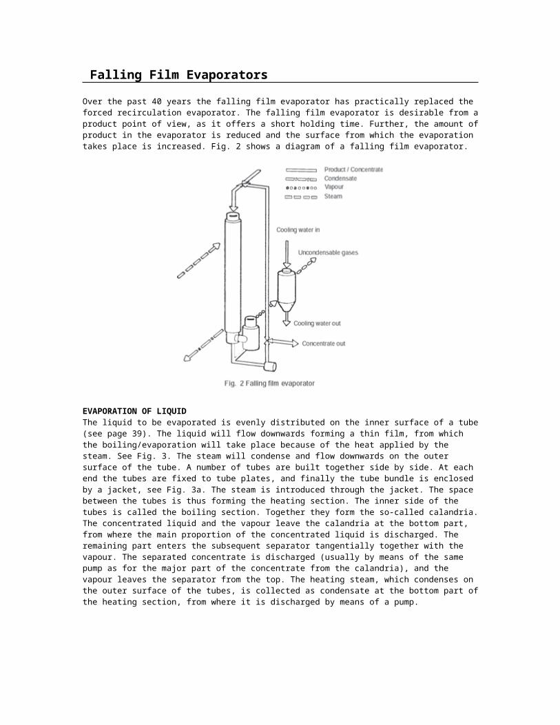
Over the past 40 years the falling film evaporator has practically replaced the forced recirculation evaporator. The falling film evaporator is desirable from a product point of view, as it offers a short holding time. Further, the amount of product in the evaporator is reduced and the surface from which the evaporation takes place is increased. Fig. 2 shows a diagram of a falling film evaporator.
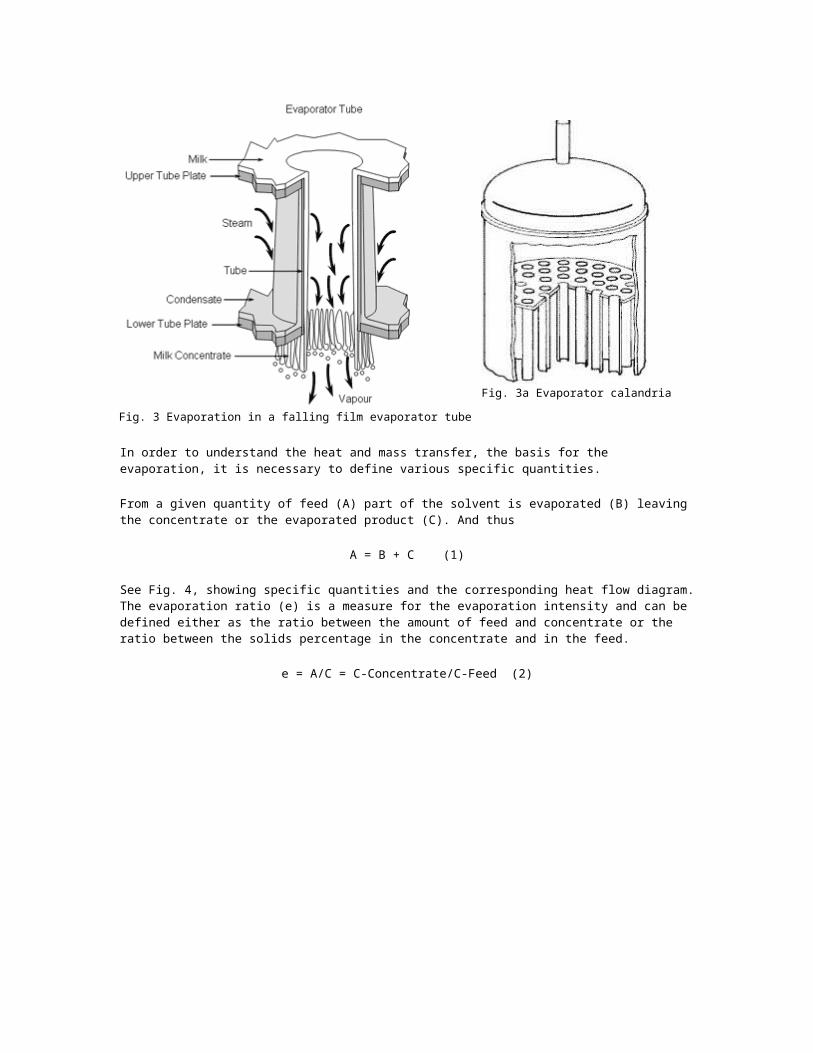
EVAPORATION OF LIQUIDThe liquid to be evaporated is evenly distributed on the inner surface of a tube (see page 39). The liquid will flow downwards forming a thin film, from which the boiling/evaporation will take place because of the heat applied by the steam. See Fig. 3. The steam will condense and flow downwards on the outer surface of the tube. A number of tubes are built together side by side. At each end the tubes are fixed to tube plates, and finally the tube bundle is enclosed by a jacket, see Fig. 3a. The steam is introduced through the jacket. The space between the tubes is thus forming the heating section. The inner side of the tubes is called the boiling section. Together they form the so-called calandria. The concentrated liquid and the vapour leave the calandria at the bottom part, from where the main proportion of the concentrated liquid is discharged. The remaining part enters the subsequent separator tangentially together with the vapour. The separated concentrate is discharged (usually by means of the same pump as for the major part of the concentrate from the calandria), and the vapour leaves the separator from the top. The heating steam, which condenses on the outer surface of the tubes, is collected as condensate at the bottom part of the heating section, from where it is discharged by means of a pump.
Fig. 3 Evaporation in a falling film evaporator tube
Fig. 3a Evaporator calandria
In order to understand the heat and mass transfer, the basis for the evaporation, it is necessary to define various specific quantities.
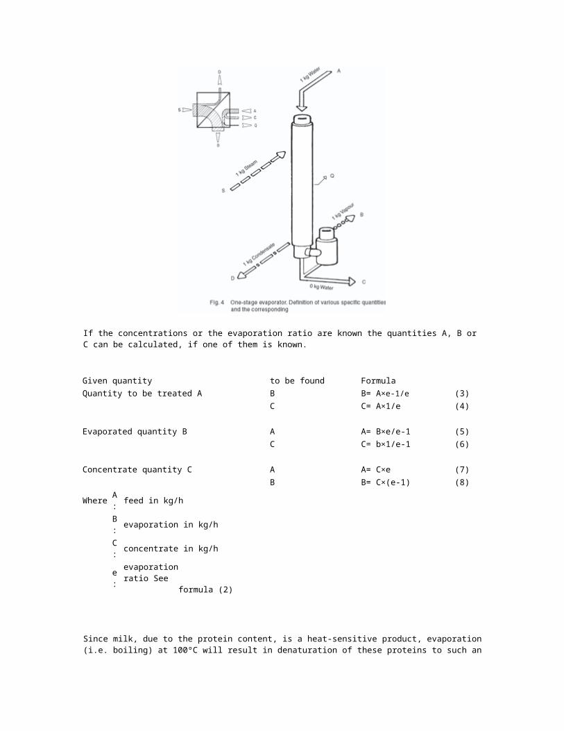
From a given quantity of feed (A) part of the solvent is evaporated (B) leaving the concentrate or the evaporated product (C). And thus
A = B + C (1)
See Fig. 4, showing specific quantities and the corresponding heat flow diagram.The evaporation ratio (e) is a measure for the evaporation intensity and can be defined either as the ratio between the amount of feed and concentrate or the ratio between the solids percentage in the concentrate and in the feed.
e = A/C = C-Concentrate/C-Feed (2)
If the concentrations or the evaporation ratio are known the quantities A, B or C can be calculated, if one of them is known.
Given quantity to be found FormulaQuantity to be treated A B B= A×e-1/e (3)
C C= A×1/e (4)
Evaporated quantity B A A= B×e/e-1 (5)C C= b×1/e-1 (6)
Concentrate quantity C A A= C×e (7)B B= C×(e-1) (8)
Where A: feed in kg/hB: evaporation in kg/hC: concentrate in kg/he: evaporation ratio See formula (2)
Since milk, due to the protein content, is a heat-sensitive product, evaporation (i.e. boiling) at 100ºC will result in denaturation of these proteins to such an extent that the final product is considered unfit for consumption. The boiling section is therefore operated under vacuum, which means that the boiling/evaporation takes place at a lower temperature than that corresponding to the normal atmospheric pressure. The vacuum is created by a vacuum pump prior to start-up of the evaporator and is main-tained by condensing the vapour by means of cooling water. A vacuum pump or simi-lar is used to evacuate incondensable gases from the milk.
At 100ºC the evaporation enthalpy of water is 539 Kcal/kg and at 60ºC it is 564 Kcal/kg. As the
milk has to be heated from e.g. 6ºC to the boiling point, and as en-ergy, approx. 20 Kcal/kg, is required for maintaining a vacuum corresponding to a boiling point of 60ºC, we get the following energy consumption figures, provided we estimate the heat loss to be 2%:
corresponding to about 1.1 kg steam/kg evaporated water.
To simplify the following examples we will use 1 kg steam/kg evaporated water.As vapour, see Fig. 4, from the evaporated milk contains almost all the applied energy, it is obvious to utilize this to evaporate more water by condensing the vapour. This is done by adding another calandria to the evaporator. This new calandria - the second effect - where the boiling temperature is lower, now works as condenser for the vapours from the first effect, and the energy in the vapour is thus utilized as it condenses.
In order to obtain a temperature difference in the second effect between the product and
vapour coming from the first effect, the boiling section of the second effect is operated at a higher vacuum corresponding to a lower boiling temperature.
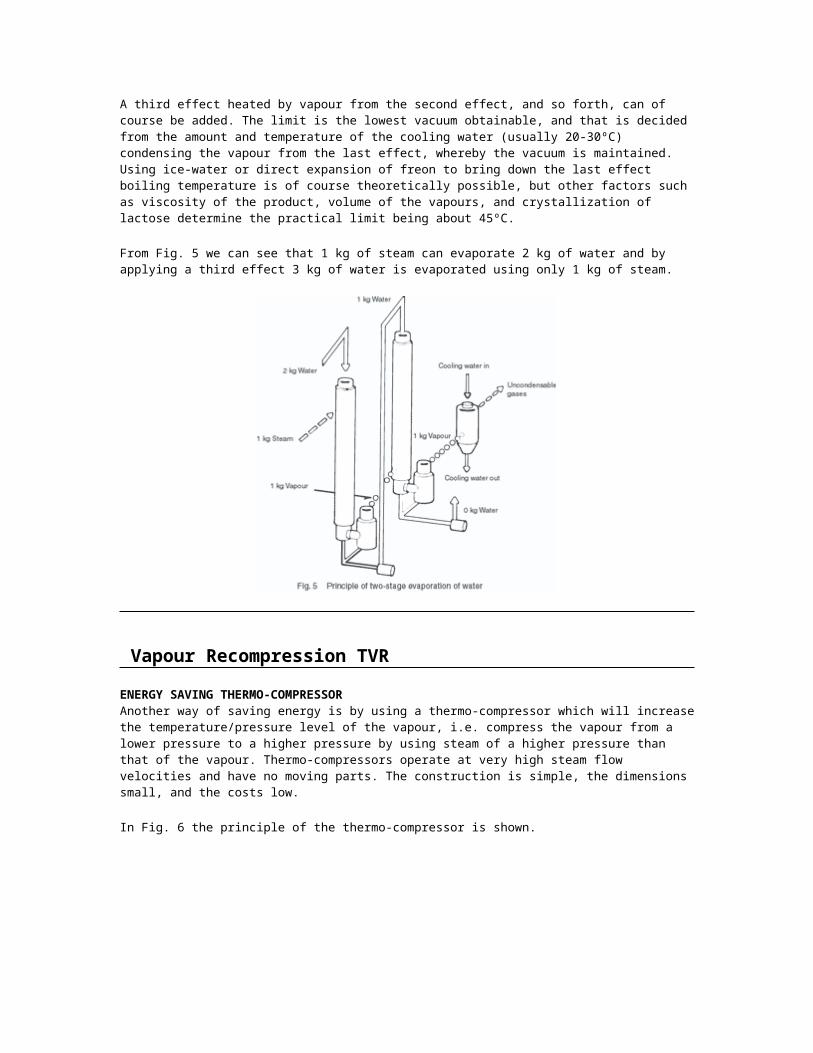
A third effect heated by vapour from the second effect, and so forth, can of course be added. The limit is the lowest vacuum obtainable, and that is decided from the amount and temperature of the cooling water (usually 20-30ºC) condensing the vapour from the last effect, whereby the vacuum is maintained. Using ice-water or direct expansion of freon to bring down the last effect boiling temperature is of course theoretically possible, but other factors such as viscosity of the product, volume of the vapours, and crystallization of lactose determine the practical limit being about 45ºC.
From Fig. 5 we can see that 1 kg of steam can evaporate 2 kg of water and by applying a third effect 3 kg of water is evaporated using only 1 kg of steam.
Vapour Recompression TVR
ENERGY SAVING THERMO-COMPRESSORAnother way of saving energy is by using a thermo-compressor which will increase the temperature/pressure level of the vapour, i.e. compress the vapour from a lower pressure to a higher pressure by using steam of a higher pressure than that of the vapour. Thermo-compressors operate at very high steam flow velocities and have no moving parts. The construction is simple, the dimensions small, and the costs low.
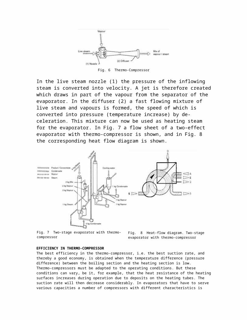
In Fig. 6 the principle of the thermo-compressor is shown.
Fig. 6 Thermo-Compressor
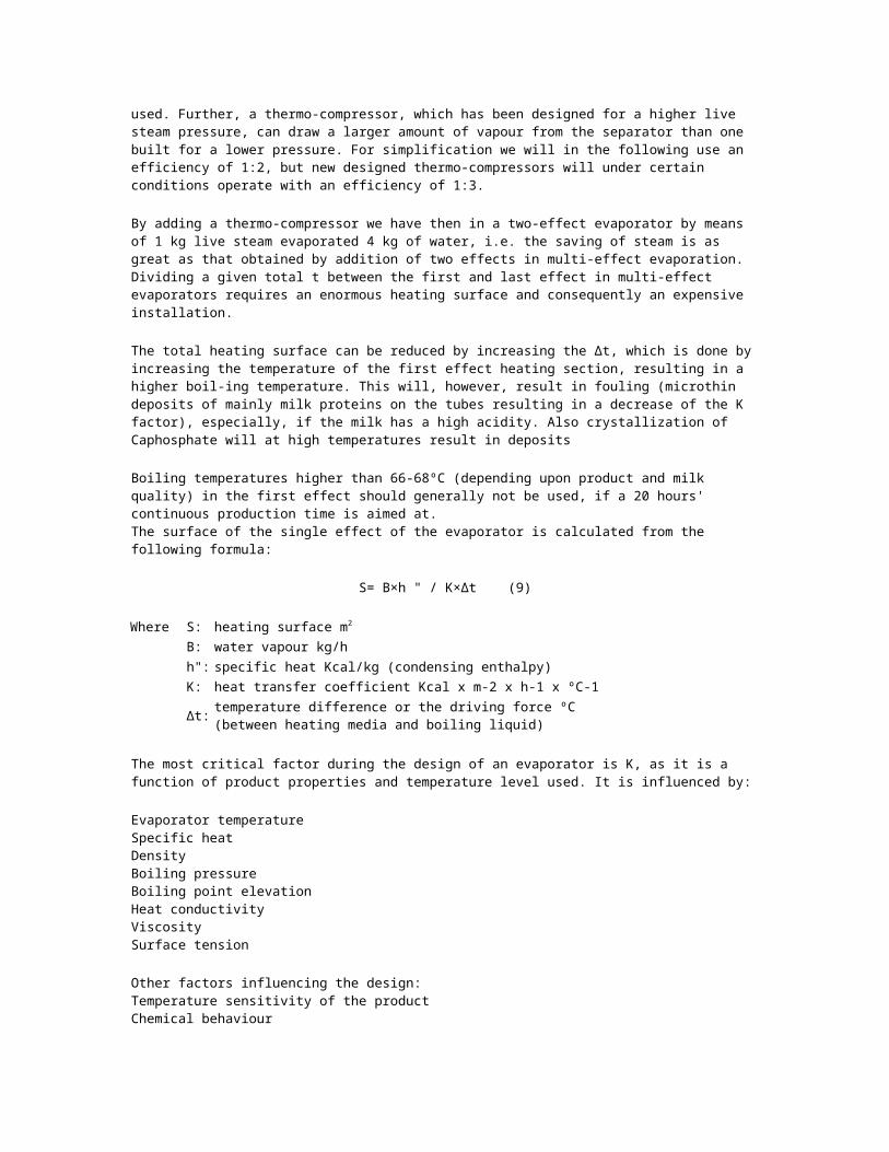
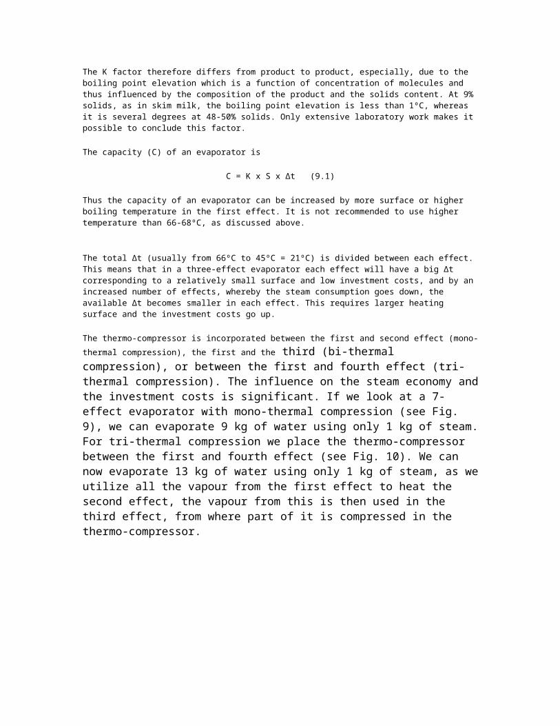
In the live steam nozzle (1) the pressure of the inflowing steam is converted into velocity. A jet is therefore created which draws in part of the vapour from the separator of the evaporator. In the diffuser (2) a fast flowing mixture of live steam and vapours is formed, the speed of which is converted into pressure (temperature increase) by de-celeration. This mixture can now be used as heating steam for the evaporator. In Fig. 7 a flow sheet of a two-effect evaporator with thermo-compressor is shown, and in Fig. 8 the corresponding heat flow diagram is shown.
Fig. 7 Two-stage evaporator with thermo-compressor
Fig. 8 Heat-flow diagram. Two-stage evaporator with thermo-compressor
EFFICIENCY IN THERMO-COMPRESSORThe best efficiency in the thermo-compressor, i.e. the best suction rate, and thereby a good economy, is obtained when the temperature difference (pressure difference) between the boiling section and the heating section is low.Thermo-compressors must be adapted to the operating conditions. But these conditions can vary, be it, for example, that the heat resistance of the heating surfaces increases during operation due to deposits on the heating tubes. The suction rate will then decrease considerably. In evaporators that have to serve various capacities a number of compressors with different characteristics is used. Further, a thermo-compressor, which has been designed for a higher live steam pressure, can draw a larger amount of vapour from the separator than one built for a lower pressure. For simplification we will in the following use an efficiency of 1:2, but new designed thermo-compressors will under certain conditions operate with an efficiency of 1:3.
By adding a thermo-compressor we have then in a two-effect evaporator by means of 1 kg live steam evaporated 4 kg of water, i.e. the saving of steam is as great as that obtained by addition of two effects in multi-effect evaporation. Dividing a given total t between the first and last effect in multi-effect evaporators requires an enormous heating surface and consequently an expensive installation.
The total heating surface can be reduced by increasing the ∆t, which is done by increasing the temperature of the first effect heating section, resulting in a higher boil-ing temperature. This will, however, result in fouling (microthin deposits of mainly milk proteins on the tubes resulting in a decrease of the K factor), especially, if the milk has a high acidity. Also crystallization of Caphosphate will at high temperatures result in deposits
Boiling temperatures higher than 66-68ºC (depending upon product and milk quality) in the first effect should generally not be used, if a 20 hours' continuous production time is aimed at.The surface of the single effect of the evaporator is calculated from the following formula:
S= B×h " / K×∆t (9)
Where S: heating surface m2
B: water vapour kg/hh": specific heat Kcal/kg (condensing enthalpy)K: heat transfer coefficient Kcal x m-2 x h-1 x ºC-1∆t: temperature difference or the driving force ºC
(between heating media and boiling liquid)
The most critical factor during the design of an evaporator is K, as it is a function of product properties and temperature level used. It is influenced by:
Evaporator temperatureSpecific heatDensityBoiling pressureBoiling point elevationHeat conductivityViscositySurface tension
Other factors influencing the design:Temperature sensitivity of the productChemical behaviour
The K factor therefore differs from product to product, especially, due to the boiling point elevation which is a function of concentration of molecules and thus influenced by the composition of the product and the solids content. At 9% solids, as in skim milk, the boiling point elevation is less than 1ºC, whereas it is several degrees at 48-50% solids. Only extensive laboratory work makes it possible to conclude this factor.
The capacity (C) of an evaporator is
C = K x S x ∆t (9.1)
Thus the capacity of an evaporator can be increased by more surface or higher boiling temperature in the first effect. It is not recommended to use higher temperature than 66-68ºC, as discussed above.
The total ∆t (usually from 66ºC to 45ºC = 21ºC) is divided between each effect. This means that in a three-effect evaporator each effect will have a big ∆t corresponding to a relatively small surface and low investment costs, and by an increased number of effects, whereby the steam consumption goes down, the available ∆t becomes smaller in each effect. This requires larger heating surface and the investment costs go up.
The thermo-compressor is incorporated between the first and second effect (mono-thermal
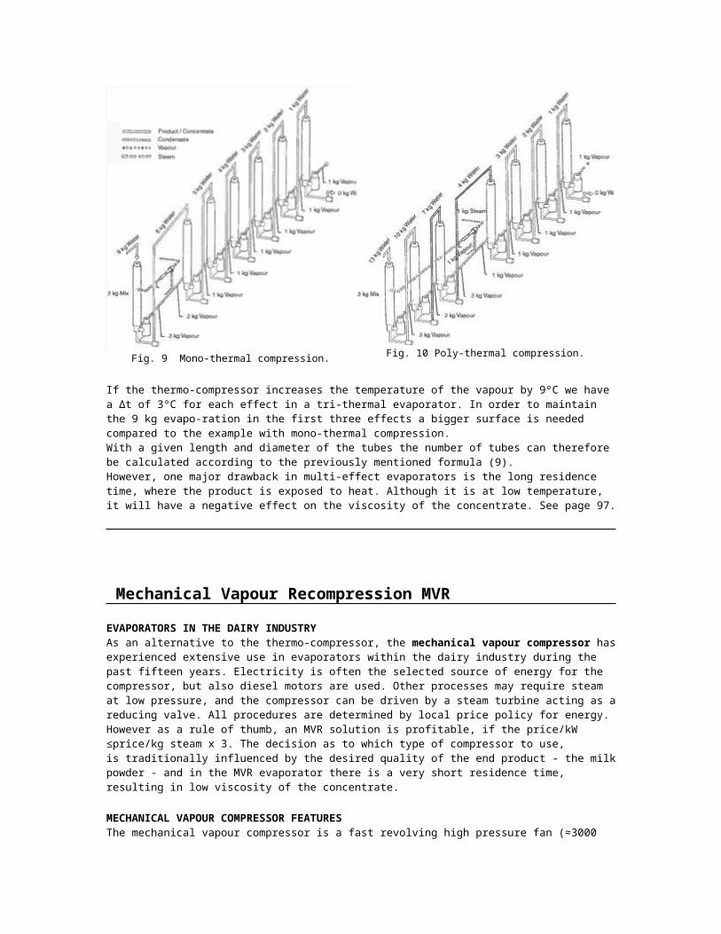
compression), the first and the third (bi-thermal compression), or between the first and fourth effect (tri-thermal compression). The influence on the steam economy and the investment costs is significant. If we look at a 7-effect evaporator with mono-thermal compression (see Fig. 9), we can evaporate 9 kg of water using only 1 kg of steam. For tri-thermal compression we place the thermo-compressor between the first and fourth effect (see Fig. 10). We can now evaporate 13 kg of water using only 1 kg of steam, as we utilize all the vapour from the first effect to heat the second effect, the vapour from this is then used in the third effect, from where part of it is compressed in the thermo-compressor.
If the thermo-compressor increases the temperature of the vapour by 9ºC we have a ∆t of 3ºC for each effect in a tri-thermal evaporator. In order to maintain the 9 kg evapo-ration in the first three effects a bigger surface is needed compared to the example with mono-thermal compression.With a given length and diameter of the tubes the number of tubes can therefore be calculated according to the previously mentioned formula (9).However, one major drawback in multi-effect evaporators is the long residence time, where the product is exposed to heat. Although it is at low temperature, it will have a negative effect on the viscosity of the concentrate. See page 97.
Mechanical Vapour Recompression MVR
EVAPORATORS IN THE DAIRY INDUSTRYAs an alternative to the thermo-compressor, the mechanical vapour compressor has experienced extensive use in evaporators within the dairy industry during the past fifteen years. Electricity is often the selected source of energy for the compressor, but also diesel motors are used. Other processes may require steam at low pressure, and the compressor can be driven by a steam turbine acting as a reducing valve. All procedures are determined by local price policy for energy. However as a rule of thumb, an MVR solution is profitable, if the price/kW ≤price/kg steam x 3. The decision as to which type of compressor to use, is traditionally influenced by the desired quality of the end product - the milk powder - and in the MVR evaporator there is a very short residence time, resulting in low viscosity of the concentrate.
MECHANICAL VAPOUR COMPRESSOR FEATURESThe mechanical vapour compressor is a fast revolving high pressure fan (≈3000 rpm) capable of operating under vacuum. At low boiling temperatures the volume of the vapours is enormous (see page 21). Consequently, there is a limit as to the lowest temperature levels used in practice. As the energy applied to the compressor is utilized most efficiently by low compression ratios, the obtained temperature/pressure in-crease is limited. Therefore, a large heat transfer surface is required, which tends to increase the capital costs of the equipment.
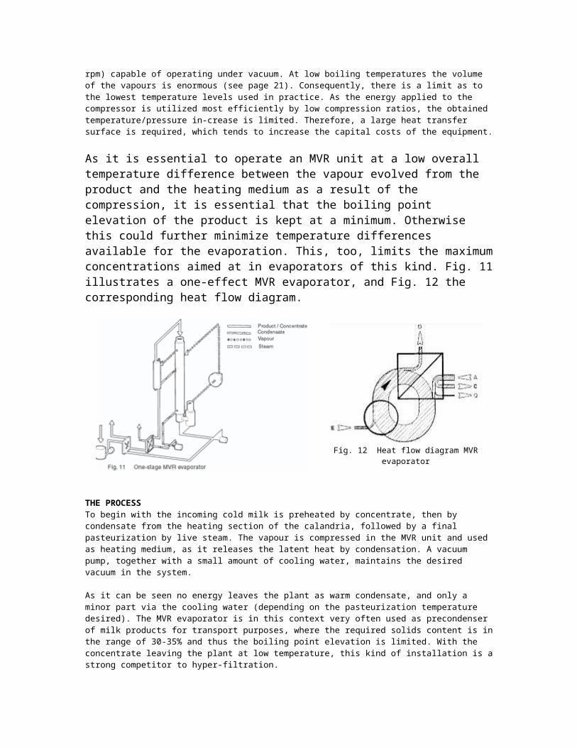
As it is essential to operate an MVR unit at a low overall temperature difference between the vapour evolved from the product and the heating medium as a result of the compression, it is essential that the boiling point elevation of the product is kept at a minimum. Otherwise this could further minimize temperature differences available for the evaporation. This, too, limits the maximum concentrations aimed at in evaporators of this kind. Fig. 11 illustrates a one-effect MVR evaporator, and Fig. 12 the corresponding heat flow diagram.
Fig. 12 Heat flow diagram MVR evaporator
THE PROCESSTo begin with the incoming cold milk is preheated by concentrate, then by condensate from the heating section of the calandria, followed by a final pasteurization by live steam. The vapour is compressed in the MVR unit and used as heating medium, as it releases the latent heat by condensation. A vacuum pump, together with a small amount of cooling water, maintains the desired vacuum in the system.
As it can be seen no energy leaves the plant as warm condensate, and only a minor part via the cooling water (depending on the pasteurization temperature desired). The MVR evaporator is in this context very often used as precondenser of milk products for transport purposes, where the required solids content is in the range of 30-35% and thus the boiling point elevation is limited. With the concentrate leaving the plant at low temperature, this kind of installation is a strong competitor to hyper-filtration.
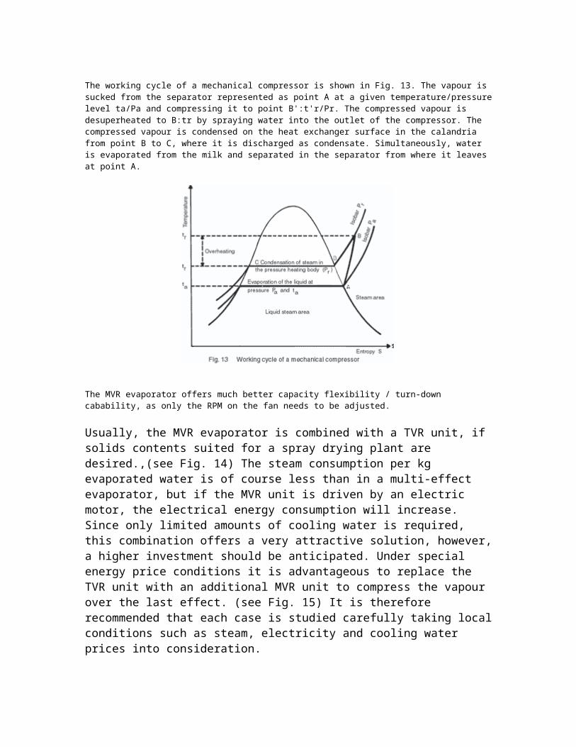
The working cycle of a mechanical compressor is shown in Fig. 13. The vapour is sucked from the separator represented as point A at a given temperature/pressure level ta/Pa and compressing it to point B':t'r/Pr. The compressed vapour is desuperheated to B:tr by spraying water into the outlet of the compressor. The compressed vapour is condensed on the heat exchanger surface in the calandria from point B to C, where it is discharged as condensate. Simultaneously, water is evaporated from the milk and separated in the separator from where it leaves at point A.
The MVR evaporator offers much better capacity flexibility / turn-down cabability, as only the RPM on the fan needs to be adjusted.
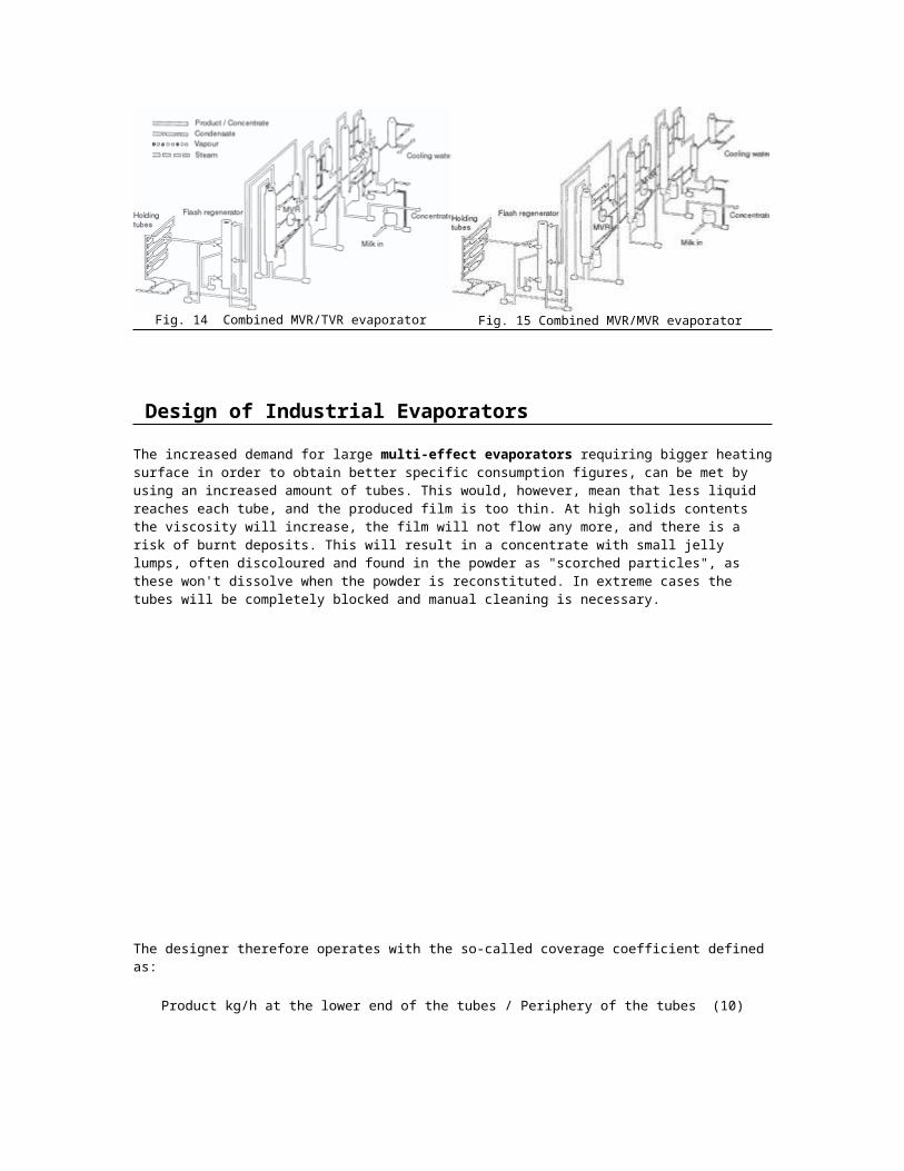
Usually, the MVR evaporator is combined with a TVR unit, if solids contents suited for a spray drying plant are desired.,(see Fig. 14) The steam consumption per kg evaporated water is of course less than in a multi-effect evaporator, but if the MVR unit is driven by an electric motor, the electrical energy consumption will increase. Since only limited amounts of cooling water is required, this combination offers a very attractive solution, however, a higher investment should be anticipated. Under special energy price conditions it is advantageous to replace the TVR unit with an additional MVR unit to compress the vapour over the last effect. (see Fig. 15) It is therefore recommended that each case is studied carefully taking local conditions such as steam, electricity and cooling water prices into consideration.
The increased demand for large multi-effect evaporators requiring bigger heating surface in order to obtain better specific consumption figures, can be met by using an increased amount
of tubes. This would, however, mean that less liquid reaches each tube, and the produced film is too thin. At high solids contents the viscosity will increase, the film will not flow any more, and there is a risk of burnt deposits. This will result in a concentrate with small jelly lumps, often discoloured and found in the powder as "scorched particles", as these won't dissolve when the powder is reconstituted. In extreme cases the tubes will be completely blocked and manual cleaning is necessary.
The designer therefore operates with the so-called coverage coefficient defined as:
Product kg/h at the lower end of the tubes / Periphery of the tubes (10)
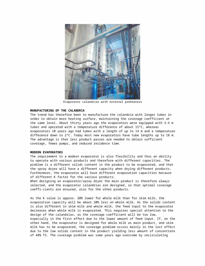
Evaporator calandrias with external preheaters
MANUFACTURING OF THE CALANDRIAThe trend has therefore been to manufacture the calandria with longer tubes in order to obtain more heating surface, maintaining the coverage coefficient at the same level. About thirty years ago the evaporators were equipped with 3-4 m tubes and operated with a temperature difference of about 15ºC, whereas evaporators 10 years ago had tubes with a length of up to 14 m and a temperature difference down to 2ºC. Today most new evaporators have tube
lengths up to 18 m. The advantage is that less product passes are needed to obtain sufficient coverage, fewer pumps, and reduced residence time.
MODERN EVAPORATORSThe requirement to a modern evaporator is also flexibility and thus an ability to operate with various products and therefore with different capacities. The problem is a different solids content in the product to be evaporated, and that the spray dryer will have a different capacity when drying different products. Furthermore, the evaporator will have different evaporation capacities because of different K factor for the various products.When designing an evaporator/spray dryer the main product is therefore always selected, and the evaporator calandrias are designed, so that optimal coverage coeffi-cients are ensured, also for the other products.
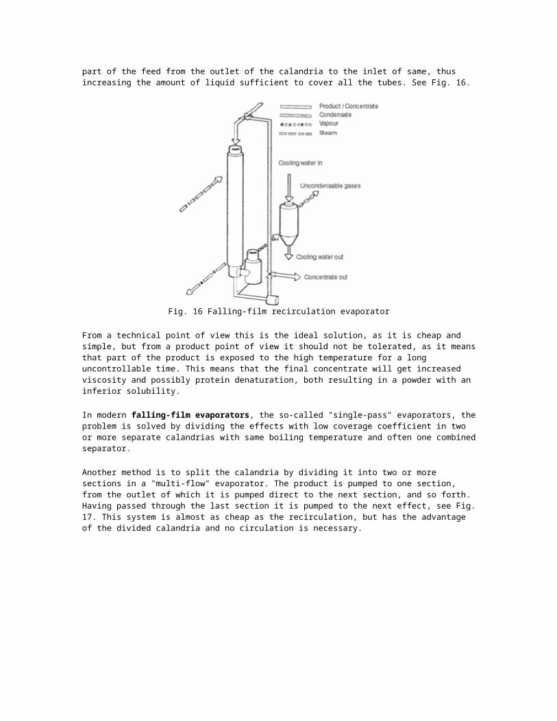
As the K value is approx. 20% lower for whole milk than for skim milk, the evaporation capacity will be about 20% less on whole milk. As the solids content is also different in skim milk and whole milk, the feed input to the evaporator decreases when whole milk is evaporated. This requires special attention to the design of the calandrias, as the coverage coefficient will be too low, especially in the first effect due to the lower amount of feed input. If, on the other hand, the evaporator is designed for whole milk as main product, and skim milk has to be evaporated, the coverage problem occurs mainly in the last effect due to the low solids content in the product yielding less amount of concentrate of 48% TS. The coverage problem was some years ago overcome by recirculating part of the feed from the outlet of the calandria to the inlet of same, thus increasing the amount of liquid sufficient to cover all the tubes. See Fig. 16.
Fig. 16 Falling-film recirculation evaporator
From a technical point of view this is the ideal solution, as it is cheap and simple, but from a product point of view it should not be tolerated, as it means that part of the product is exposed to the high temperature for a long uncontrollable time. This means that the final concentrate will get increased viscosity and possibly protein denaturation, both resulting in a powder with an inferior solubility.
In modern falling-film evaporators, the so-called "single-pass" evaporators, the problem is solved by dividing the effects with low coverage coefficient in two or more separate calandrias with same boiling temperature and often one combined separator.
Another method is to split the calandria by dividing it into two or more sections in a "multi-flow" evaporator. The product is pumped to one section, from the outlet of which it is pumped direct to the next section, and so forth. Having passed through the last section it is pumped to the next effect, see Fig. 17. This system is almost as cheap as the recirculation, but has the advantage of the divided calandria and no circulation is necessary.
Condensation Equipment
Condensing for the vapours and maintaining vacuum can be done two ways, either using a mixing condenser or surface condenser.
Dairy industry evaporators operate under vacuum and are therefore equipped with air evacuation and condensation installation to condense the vapour unsuited for use and to create and maintain vacuum in the plant. The amount of heat the condenser has to discharge depends on the amount of residual vapours from the last effect and the temperature.
To save cooling water and energy, the milk to be evaporated (with a temperature of 5-10ºC) is used to precool the vapours while the milk is simultaneously being preheated. However, the final condensation is done with cooling water. Air and uncondensable gases will be present in the milk to be evaporated as well as small leaks in the plant. It is therefore necessary to have some equipment that can extract this air/gas to maintain the vacuum. The same equipment is used to create the vacuum during start-up.
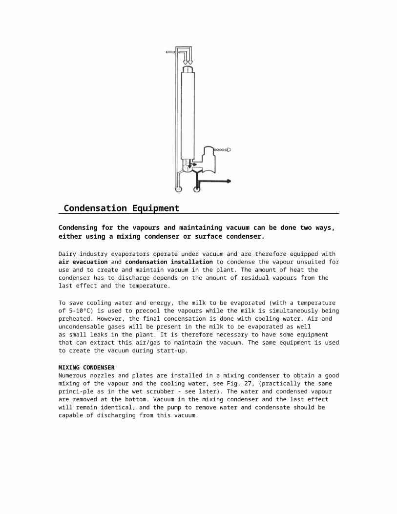
MIXING CONDENSERNumerous nozzles and plates are installed in a mixing condenser to obtain a good mixing of the vapour and the cooling water, see Fig. 27, (practically the same princi-ple as in the wet scrubber - see later). The water and condensed vapour are removed at the bottom. Vacuum in the mixing condenser and the last effect will remain identical, and the pump to remove water and condensate should be capable of discharging from this vacuum.
Fig. 27 Mixing condenser
A second solution is placing the mixing condenser barometrically high, i.e. about 11 meter above the pump. This will allow the water to run into a well from where it is pumped away, either to a cooling tower or to a natural water reservoir.
The advantages of mixing condenser are low investment costs and lower cooling water consumption. The disadvantage is that condensate is mixed with the cooling water which could lead to a contaminated cooling tower.
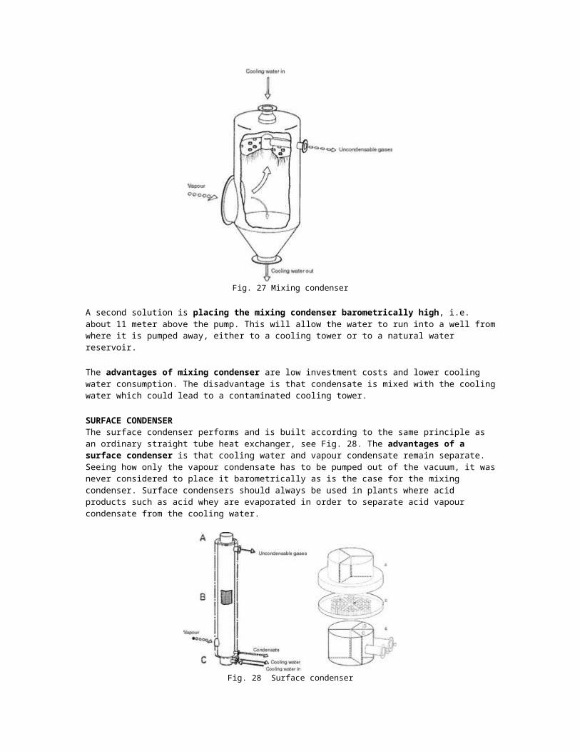
SURFACE CONDENSERThe surface condenser performs and is built according to the same principle as an ordinary straight tube heat exchanger, see Fig. 28. The advantages of a surface condenser is that cooling water and vapour condensate remain separate. Seeing how only the vapour condensate has to be pumped out of the vacuum, it was never considered to place it barometrically as is the case for the mixing condenser. Surface condensers should always be used in plants where acid products such as acid whey are evaporated in order to separate acid vapour condensate from the cooling water.
Fig. 28 Surface condenser
Concentrate Properties
The last concentrate leaving the evaporator is liquid. This concentrate may however have different viscosity depending upon the composition, heat sensitivity of the proteins, pretreatment, temperature and solids content.
THE EFFECT OF VISCOCITYWhole milk concentrates are generally less viscous than skim milk concentrates, and as a general rule the viscosity should not exceed 60 and 100 cP, respectively, if the atomization should be optimal.
Higher viscosities can of course be handled in the dryer, but not without losing capacity (bad atomization - big droplets) and the result is an inferior product.
The composition will influence the viscosity, especially on the protein (P) content in relation to the lactose (L) content. When the ratio P:L is high the concentrate will get a high viscosity. This is especially a problem with jersey cows during the entire year, while other breeds tend to give problems during the beginning of the lactation period. The ratio P:L can be adjusted by adding lactose. As a general rule it can be concluded that a higher fat and lactose content will result in lower viscosity. Higher protein content will give higher viscosity.
HIGH HEAT TREATMENTWhen milk is exposed to a high heat treatment, especially in indirect pasteurizing systems, prior to the evaporation, the viscosity of the concentrate will be higher.
The concentrate temperature will naturally have a direct influence on the viscosity and higher temperature means lower viscosity.
The solids content of the concentrate will have a very significant influence on the viscosity, and the higher the concentration the higher the viscosity.
PARAMETERS AFFECTING VISCOSITYHowever, the above only states the direct influence of some parameters on the viscosity. One of the main influences on viscosity is time, i.e. the viscosity is a function of time, also known as age-thickening. This means that the viscosity will increase if the concentrate is left for some time. The increase depends on composition, mainly proteins binding to each other, temperature and concentration. The age-thickening is only partly reversible by agitation.
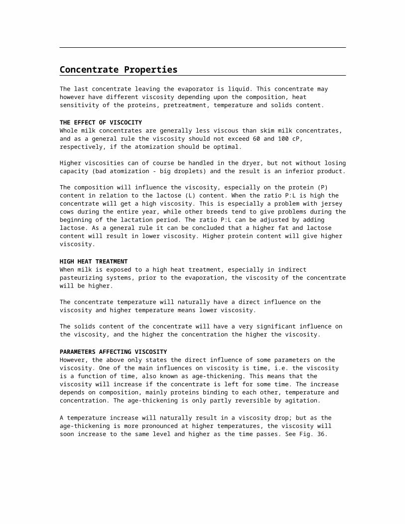
A temperature increase will naturally result in a viscosity drop; but as the age-thickening is more pronounced at higher temperatures, the viscosity will soon increase to the same level and higher as the time passes. See Fig. 36.
Fig. 36 Age-thickening as a function of temperature (skim milk 48.5% solids)
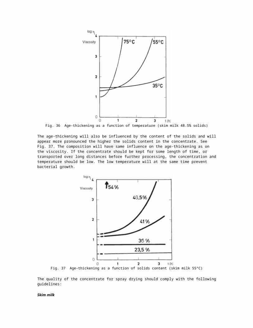
The age-thickening will also be influenced by the content of the solids and will appear more pronounced the higher the solids content in the concentrate. See Fig. 37. The composition will have same influence on the age-thickening as on the viscosity. If the concentrate should be kept for some length of time, or transported over long distances before further processing, the concentration and temperature should be low. The low temperature will at the same time prevent bacterial growth.
Fig. 37 Age-thickening as a function of solids content (skim milk 55°C)
The quality of the concentrate for spray drying should comply with the following guidelines:
Skim milk
Solids content: 48-50% TS
Viscosity: max. 100 Cp at 40ºC measured on the feed to be atomized. Measurements on concentrate not older than 15 min. and kept under vacuum between evaporator and sampling for viscosity measurements. Method Brookfield viscometer model LVT with spindle 2, rotation 60 rpm, measured at 40ºC.
Protein denaturation: For instant products the WPNI should be 2.5-3.5 mg. For high bulk density powders the WPNI should be max. 1.0 mg.
Solubility index: no measurable amount.
Sieving test: no visible insolubles (cheesy flakes) on 250 micron mesh after passing 1 litre of concentrate through the mesh and washing with water.
Scorched particles: no measurable amount.
Whole Milk
Solids content: 48-50% TS
Viscosity: Max. 60 Cp at 40ºC measured on the feed to be atomized. Measurements on concentrate not older than 15 min. and kept under vacuum between evaporator and sampling for viscosity measurements. Method Brookfield viscometer model LVT with spindle 2, rotation 60 rpm, measured at 40ºC.
Protein denaturation: For instant products the WPNI should be 2.5-3.5 mg. For high bulk density powders the WPNI should be max. 1.0 mg, based on SNF.
Solubility index: no measurable amount.
Sieving test: no visible insolubles (cheesy flakes) on 250 micron mesh after passing 1 litre of concentrate through the mesh and washing with water.
Scorched particles: no measurable amount.
Whey
Solids content: min. 52% TS
Crystallization degree: > 75% of the lactose to be crystallized,mean crystal size: 30 micronsbiggest crystal size: 50 microns
Viscosity : max. 1000 Cp at 40ºC measured on the feed to be atomized. Method Brookfield viscometer model LVT with spindle 2, rotation 60 rpm, measured at 40ºC.
Protein denaturation: Whey proteins should be max. 25% denatured (approx. 80ºC, 15 sec. pasteurization in evaporator)
Solubility index: no measurable amount
Sieving test : no visible insolubles (cheesy flakes) on 250 micron mesh after passing 1 litre of concentrate through the mesh and washing with water.
Scorched particles: no measurable amount.
Atomizing Device
The aim of atomizing the concentrate is to provide a very large surface, from which the evaporation can take place. The smaller droplets, the bigger surface, the easier evaporation, and a better thermal efficiency of the dryer is obtained. The ideal from a drying point of view would be a spray of drops of same size, which would mean that the drying time for all particles would be the same for obtaining an equal moisture content. In practice, however, no atomizing device has yet been designed to produce a completely homogenous spray, although present designs have a high degree of homo-geneity. From a powder bulk density point of view a homogenous spray is not wanted, as this would mean a powder with low bulk density, and that would mean an increase in packing material. It is, however, so that today's achievement of atomizing facilitates both the drying and the powder bulk density.
As mentioned previously the air distribution and atomization are the key factors to a successful utilization of the spray dryer. The atomization is directly responsible for many distinctive advantages offered by the spray drying. First, the very short drying time of the particles can be mentioned, secondly a very short particle retention time in the hot atmosphere and low particle temperature (wet bulb temperature) and finally the transformation of the liquid feed into a powder with long storage stability ready for packing and transport.
Summarized, the prime function of atomization is:
a high surface to mass ratio resulting in high evaporation rates, production of particles of the desired shape, size and density.
To comply with these requirements many atomization techniques have been used in spray dryers. However, the most common ones can be summarized as follows:
Pressure energy as in pressure nozzles Kinetic energy as in two-fluid nozzles Centrifugal energy as in rotating discs
The mechanism of atomization has been studied by many scientists, and though the first pioneers started more than 100 years ago, the subject is still highly controversial in spite of many published data.
Atomization in Spray Dryers for Milk Products
Pressure nozzles and Rotary nozzles are used in the Dairy Industry, whereas the pneumatic nozzle requires too high energy and the end powder consists of too fine particles and is not attractive to the consumer.
PRESSURE NOZZLESThe high pressure low capacity nozzles are mainly used in box dryers working as one-stage dryers, see page 123, and operate at a high pressure 300-400 bar g. Each nozzle will have a capacity of 50-150 kg concentrate, usually with only 40-42% solids, if a reasonable solubility should be maintained in the powder. The actual plant will therefore be equipped with numerous nozzles, all of which are with very small orifices which get easily blocked. Normally, the powder has a high bulk density, but tends to be dusty, as it consists of small particles. Due to the low solids requirements the drying becomes at the same time expensive.
Pressure nozzle atomizer assembly with fines return arrangement
The low pressure high capacity nozzles with a capacity of up to 1000-1500 kg/h have gained more and more use after the development of the two-stage drying process, where the particle temperature is much lower. The solids content can therefore be increased to 48% and the pressure decreased (150-200 bar g) without affecting the solubility, thus making nozzle atomization interesting also from an economical point of view.
The advantages of pressure nozzles can be summarized as follows:
Powder with low occluded air Powder with high bulk density Improved flowability, especially in whole milk Tendency to give less deposits in the drying chamber
when difficult products are produced Ability to produce big particles If a dual feed/nozzle system is used, the drying plant can operate continuously 24
h/day for weeks without stop, only the feed line/nozzles are wet-cleaned after 20 hours.
ROTARY ATOMIZERThe rotary atomizer has been known and used in the dairy industry for many years, the main advantages are:
Flexibility as to through-put Ability to handle large quantities
Ability to handle highly viscous concentrates Different wheel designs giving different powder characteristics Ability to handle products with crystals Higher solids content in the feed is possible, therefore better economy
To decide whether to use pressure nozzles or rotary wheel is therefore a question of type of product.
For conventional milk products as well as crystallized whey concentrate the rotary wheel will be the preferred atomizing device, whereas for very high density powders and instant whole milk powder and other products with high fat content, the high-capacity low-pressure nozzles should be used in connection with two-stage drying.As it is impossible to predict what type of product should be produced tomorrow, there has been a tendency to select dryers capable of using both systems, i.e. they should be directly interchangeable.