28
FAN-PWM-V3 Instructions
| Date post: | 23-May-2018 |
| Category: |
Documents |
| Upload: | truongngoc |
| View: | 224 times |
| Download: | 1 times |
FAN-PWM-V3Instructions

www.spalusa.com1
Parts Included In Kit
OEM TEMP SENSOR HARNESS
MAIN HARNESS
POWER HARNESS
86
87
87a
85
30
SPAL TEMP SENSOR HARNESS
SPAL SENSOR
FAN-PWM CONTROLLER
FRH
OPTIONAL ITEMS
ITEMS INCLUDED IN KIT
HARDWARE BAG
INSTRUCTION BOOKLET
ZIP TIES(12)
FUSE HOLDER
20 AMP FUSE
30 AMP FUSE
YELLOW RING CONNECTORS (2)
BLUE RING CONNECTORS(2)
YELLOW BUTT CONNECTOR(1)
SELF TAPPING SCREWS(4)
30
20
BCU+
BA
DT06
-3S
CB
FAN-PWM-V3 Controller (1)
OEM TEMP SENSOR HARNESS
MAIN HARNESS
POWER HARNESS
86
87
87a
85
30
SPAL TEMP SENSOR HARNESS
SPAL SENSOR
FAN-PWM CONTROLLER
FRH
OPTIONAL ITEMS
ITEMS INCLUDED IN KIT
HARDWARE BAG
INSTRUCTION BOOKLET
ZIP TIES(12)
FUSE HOLDER
20 AMP FUSE
30 AMP FUSE
YELLOW RING CONNECTORS (2)
BLUE RING CONNECTORS(2)
YELLOW BUTT CONNECTOR(1)
SELF TAPPING SCREWS(4)
30
20
BCU+
BA
DT06
-3S
CB
Main Harness (1)
OEM TEMP SENSOR HARNESS
MAIN HARNESS
POWER HARNESS
86
87
87a
85
30
SPAL TEMP SENSOR HARNESS
SPAL SENSOR
FAN-PWM CONTROLLER
FRH
OPTIONAL ITEMS
ITEMS INCLUDED IN KIT
HARDWARE BAG
INSTRUCTION BOOKLET
ZIP TIES(12)
FUSE HOLDER
20 AMP FUSE
30 AMP FUSE
YELLOW RING CONNECTORS (2)
BLUE RING CONNECTORS(2)
YELLOW BUTT CONNECTOR(1)
SELF TAPPING SCREWS(4)
30
20
BCU+
BA
DT06
-3S
CB
SPAL Temp Sensor Harness (1)
OEM TEMP SENSOR HARNESS
MAIN HARNESS
POWER HARNESS
86
87
87a
85
30
SPAL TEMP SENSOR HARNESS
SPAL SENSOR
FAN-PWM CONTROLLER
FRH
OPTIONAL ITEMS
ITEMS INCLUDED IN KIT
HARDWARE BAG
INSTRUCTION BOOKLET
ZIP TIES(12)
FUSE HOLDER
20 AMP FUSE
30 AMP FUSE
YELLOW RING CONNECTORS (2)
BLUE RING CONNECTORS(2)
YELLOW BUTT CONNECTOR(1)
SELF TAPPING SCREWS(4)
30
20
BCU+
BA
DT06
-3S
CB
OEM Temp Sensor Harness (1)
OEM TEMP SENSOR HARNESS
MAIN HARNESS
POWER HARNESS
86
87
87a
85
30
SPAL TEMP SENSOR HARNESS
SPAL SENSOR
FAN-PWM CONTROLLER
FRH
OPTIONAL ITEMS
ITEMS INCLUDED IN KIT
HARDWARE BAG
INSTRUCTION BOOKLET
ZIP TIES(12)
FUSE HOLDER
20 AMP FUSE
30 AMP FUSE
YELLOW RING CONNECTORS (2)
BLUE RING CONNECTORS(2)
YELLOW BUTT CONNECTOR(1)
SELF TAPPING SCREWS(4)
30
20
BCU+
BA
DT06
-3S
CB
Power Harness (1)
Hardware Bag
Fuse Holder (1)
Yellow Butt Connector (1)
Self Tapping Screws (4)
Zip Ties (12)
OEM TEMP SENSOR HARNESS
MAIN HARNESS
POWER HARNESS
86
87
87a
85
30
SPAL TEMP SENSOR HARNESS
SPAL SENSOR
FAN-PWM CONTROLLER
FRH
OPTIONAL ITEMS
ITEMS INCLUDED IN KIT
HARDWARE BAG
INSTRUCTION BOOKLET
ZIP TIES(12)
FUSE HOLDER
20 AMP FUSE
30 AMP FUSE
YELLOW RING CONNECTORS (2)
BLUE RING CONNECTORS(2)
YELLOW BUTT CONNECTOR(1)
SELF TAPPING SCREWS(4)
30
20
BCU+
BA
DT06
-3S
CB
20 Amp Fuse (1) 30 Amp Fuse (1)
OEM TEMP SENSOR HARNESS
MAIN HARNESS
POWER HARNESS
86
87
87a
85
30
SPAL TEMP SENSOR HARNESS
SPAL SENSOR
FAN-PWM CONTROLLER
FRH
OPTIONAL ITEMS
ITEMS INCLUDED IN KIT
HARDWARE BAG
INSTRUCTION BOOKLET
ZIP TIES(12)
FUSE HOLDER
20 AMP FUSE
30 AMP FUSE
YELLOW RING CONNECTORS (2)
BLUE RING CONNECTORS(2)
YELLOW BUTT CONNECTOR(1)
SELF TAPPING SCREWS(4)
30
20
BCU+
BA
DT06
-3S
CB
Yellow Ring Connectors (2)
OEM TEMP SENSOR HARNESS
MAIN HARNESS
POWER HARNESS
86
87
87a
85
30
SPAL TEMP SENSOR HARNESS
SPAL SENSOR
FAN-PWM CONTROLLER
FRH
OPTIONAL ITEMS
ITEMS INCLUDED IN KIT
HARDWARE BAG
INSTRUCTION BOOKLET
ZIP TIES(12)
FUSE HOLDER
20 AMP FUSE
30 AMP FUSE
YELLOW RING CONNECTORS (2)
BLUE RING CONNECTORS(2)
YELLOW BUTT CONNECTOR(1)
SELF TAPPING SCREWS(4)
30
20
BCU+
BA
DT06
-3S
CB
Blue Ring Connectors (2)
OEM TEMP SENSOR HARNESS
MAIN HARNESS
POWER HARNESS
86
87
87a
85
30
SPAL TEMP SENSOR HARNESS
SPAL SENSOR
FAN-PWM CONTROLLER
FRH
OPTIONAL ITEMS
ITEMS INCLUDED IN KIT
HARDWARE BAG
INSTRUCTION BOOKLET
ZIP TIES(12)
FUSE HOLDER
20 AMP FUSE
30 AMP FUSE
YELLOW RING CONNECTORS (2)
BLUE RING CONNECTORS(2)
YELLOW BUTT CONNECTOR(1)
SELF TAPPING SCREWS(4)
30
20
BCU+
BA
DT06
-3S
CB
Optional Equipment
OEM TEMP SENSOR HARNESS
MAIN HARNESS
POWER HARNESS
86
87
87a
85
30
SPAL TEMP SENSOR HARNESS
SPAL SENSOR
FAN-PWM CONTROLLER
FRH
OPTIONAL ITEMS
ITEMS INCLUDED IN KIT
HARDWARE BAG
INSTRUCTION BOOKLET
ZIP TIES(12)
FUSE HOLDER
20 AMP FUSE
30 AMP FUSE
YELLOW RING CONNECTORS (2)
BLUE RING CONNECTORS(2)
YELLOW BUTT CONNECTOR(1)
SELF TAPPING SCREWS(4)
30
20
BCU+
BA
DT06
-3S
CB
FRH(Fan Relay Harness)
SPAL Sensor
OEM TEMP SENSOR HARNESS
MAIN HARNESS
POWER HARNESS
86
87
87a
85
30
SPAL TEMP SENSOR HARNESS
SPAL SENSOR
FAN-PWM CONTROLLER
FRH
OPTIONAL ITEMS
ITEMS INCLUDED IN KIT
HARDWARE BAG
INSTRUCTION BOOKLET
ZIP TIES(12)
FUSE HOLDER
20 AMP FUSE
30 AMP FUSE
YELLOW RING CONNECTORS (2)
BLUE RING CONNECTORS(2)
YELLOW BUTT CONNECTOR(1)
SELF TAPPING SCREWS(4)
30
20
BCU+
BA
DT06
-3S
CB

www.spalusa.com 2
Suggested Fuse Values
PULLER # PUSHER # DESCRIPTION RECOMMEDNED FUSE
9”
30102061 30102053 9” High Performance Fan / Paddle Blade 2530100392 30100381 9” Fan 10
10”
30102057 30102058 10” High Performance / Paddle Blade 2530100360 30100374 10” Fan 10
11”
30102052 ------------- 11” Dual High Performance Fan / Pull 30/Per Motor30102054 30102040 11” High Performance Fan / Paddle Blade 3030101500 30101502 11” Medium Profile Fan 1530100364 30100365 11” Fan 10
12”
30102130 ------------- 12” High Performance Dual Fan / Curved Paddle 30/Per Motor30102029 30102030 12” High Performance Fan / Curved Blade 3030102038 30102025 12” High Performance Fan / Paddle Blade 3030101504 30101505 12” Medium Profile Fan 2030100375 30100384 12” Fan 10
13”
30102044 30102045 13” High Performance Fan / Curved Blade 3030101507 30101508 13” Medium Profile Fan 2030100398 30100399 13” Fan 10
14”
30102041 30102055 14” High Performance Fan / Striaght Blade 3030102042 30102056 14” High Performance Fan / Curved Blade 3030101509 30101510 14” Medium Profile Fan 2030100385 30100382 14” Fan 10
16”
30102113 ------------- 16” Extreme Performance Fan / Pull 3030102120 30102047 16” High Performance Fan / Straight Blade 3030102082 ------------- 16” High Performance Fan / Paddle Blade 3030102048 30102049 16” High Performance Fan / Curved Blade 3030101516 30101517 16” Medium Profile Fan 2030100400 30100401 16” Fan 15

www.spalusa.com3
New Features of 3rd Generation PWM
**WHY THIS MAY BE IMPORTANT FOR YOU**
• Ability to reset to any one of 3 preset temperature ranges when using FAN-PWM-TS sensor
• Smart fan diagnostics detects stalled or over current fans to prevent module damage
• New 16 bit MCU for increased resolution on temperature sensor input
• Primary fan low power starts to reduce the current spike on electrical system
• Onboard status LED and status output for vehicle interior status light
• Quality Deutsch IPD connectors on the premium harness made in USA
• Silicone rubber button membrane and case seals for improved durability
• Improved AC input timing to minimize fan operation during defrost cycles
• Single unit capable of use with both 12VDC and 24VDC systems
In an effort to add features and improve quality of the FAN-PWM the functionality of the
unit may impede previous ‘creative’ installations of FAN-PWM’s.
• A brushed DC motor MUST be connected to the fan output or the unit will report an
error code. Possible use with very low power (<4A) fans and non SPAL products may
also cause fan not found error code. SPAL USA will not guaranty this products function-
ality with NON SPAL fans as too often specifications are unknown.
• Over current protection means that the output will SHUT DOWN if the measured fan
continuous run current increases above 30A for extended periods. If running a fan ap-
proaching this amount of current draw (>25A), SPAL USA recommends that the installa-
tion also include a status light so the operator will be aware of fan status. See page 8 for
status light wiring.
• Because of timing sequences on the AC input wire when using a manual override
switch there will be a delay before the fan turns on/off with the switch.
www.spalusa.com 4
Introduction / Overview
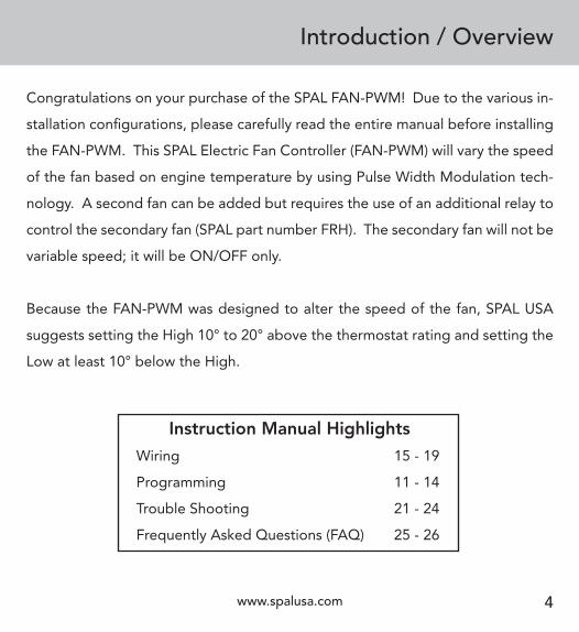
Congratulations on your purchase of the SPAL FAN-PWM! Due to the various in-
stallation configurations, please carefully read the entire manual before installing
the FAN-PWM. This SPAL Electric Fan Controller (FAN-PWM) will vary the speed
of the fan based on engine temperature by using Pulse Width Modulation tech-
nology. A second fan can be added but requires the use of an additional relay to
control the secondary fan (SPAL part number FRH). The secondary fan will not be
variable speed; it will be ON/OFF only.
Because the FAN-PWM was designed to alter the speed of the fan, SPAL USA
suggests setting the High 10° to 20° above the thermostat rating and setting the
Low at least 10° below the High.
Instruction Manual Highlights
Wiring 15 - 19
Programming 11 - 14
Trouble Shooting 21 - 24
Frequently Asked Questions (FAQ) 25 - 26
www.spalusa.com5
Operation
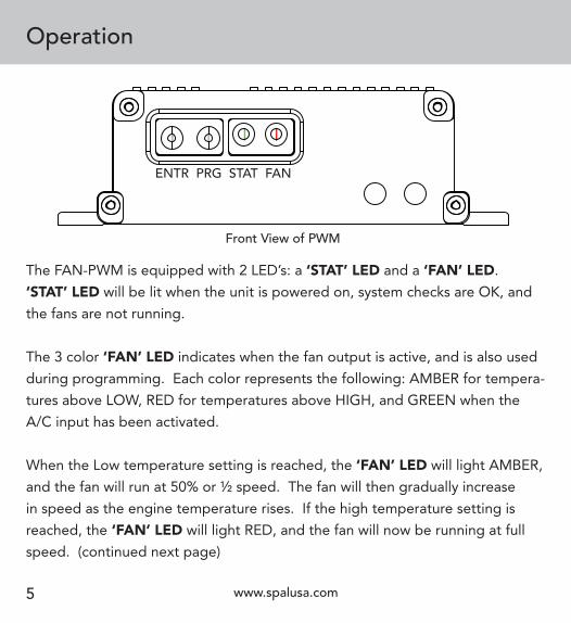
The FAN-PWM is equipped with 2 LED’s: a ‘STAT’ LED and a ‘FAN’ LED.
‘STAT’ LED will be lit when the unit is powered on, system checks are OK, and
the fans are not running.
The 3 color ‘FAN’ LED indicates when the fan output is active, and is also used
during programming. Each color represents the following: AMBER for tempera-
tures above LOW, RED for temperatures above HIGH, and GREEN when the
A/C input has been activated.
When the Low temperature setting is reached, the ‘FAN’ LED will light AMBER,
and the fan will run at 50% or ½ speed. The fan will then gradually increase
in speed as the engine temperature rises. If the high temperature setting is
reached, the ‘FAN’ LED will light RED, and the fan will now be running at full
speed. (continued next page)
Front View of PWM
ENTR PRG STAT FAN
www.spalusa.com 6
Operation(continued)
MountingThe SPAL FAN-PWM is water resistant and can be mounted in the engine bay or
inside the vehicle. Keep the controller away from high heat sources such as the
engine exhaust. Above the wheel well, on the radiator support, or firewall are
good examples of proper locations.
When the ‘FAN’ LED lights RED, a negative output will be sent on the gray wire.
This gray wire can be used to trigger a fan relay, an indicator light, etc. If you are
using dual fans with the recommended wiring setup (refer to pages 18/19) your
2nd fan will turn on full speed at this time.
If the cooling system is able to lower the coolant temperature approximately 5°
below the High setting, the ‘FAN’ LED will turn from RED to AMBER and the fan
will slow in speed; at this time the second fan output will stop as well. If the cool-
ing system is able to continue to lower the coolant temperature to approximately
5° degrees below the low setting, the ‘FAN’ LED will turn off, the ‘STAT’ LED will
light GREEN, and the fan will stop completely.
www.spalusa.com7
Temperature Sensor Connection
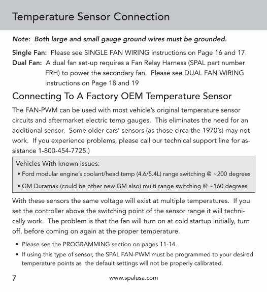
The FAN-PWM can be used with most vehicle’s original temperature sensor
circuits and aftermarket electric temp gauges. This eliminates the need for an
additional sensor. Some older cars’ sensors (as those circa the 1970’s) may not
work. If you experience problems, please call our technical support line for as-
sistance 1-800-454-7725.)
Vehicles With known issues:
• Ford modular engine’s coolant/head temp (4.6/5.4L) range switching @ ~200 degrees
• GM Duramax (could be other new GM also) multi range switching @ ~160 degrees
With these sensors the same voltage will exist at multiple temperatures. If you
set the controller above the switching point of the sensor range it will techni-
cally work. The problem is that the fan will turn on at cold startup initially, turn
off, before coming on again at the proper temperature.
• Please see the PROGRAMMING section on pages 11-14.
• If using this type of sensor, the SPAL FAN-PWM must be programmed to your desired temperature points as the default settings will not be properly calibrated.
Note: Both large and small gauge ground wires must be grounded.
Single Fan: Please see SINGLE FAN WIRING instructions on Page 16 and 17.
Dual Fan: A dual fan set-up requires a Fan Relay Harness (SPAL part number
FRH) to power the secondary fan. Please see DUAL FAN WIRING
instructions on Page 18 and 19
Connecting To A Factory OEM Temperature Sensor
www.spalusa.com 8
Temperature Sensor Connection
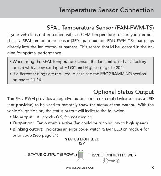
If your vehicle is not equipped with an OEM temperature sensor, you can pur-
chase a SPAL temperature sensor (SPAL part number FAN-PWM-TS) that plugs
directly into the fan controller harness. This sensor should be located in the en-
gine for optimal performance.
• When using the SPAL temperature sensor, the fan controller has a factory
preset with a Low setting of ~190° and High setting of ~205°.
• If different settings are required, please see the PROGRAMMING section
on pages 11-14.
Optional Status OutputThe FAN-PWM provides a negative output for an external device such as a LED
(not provided) to be used to remotely show the status of the system. With the
vehicle’s ignition on, the status output will indicate the following:
• No output: All checks OK, fan not running
• Output on: Fan output is active (fan could be running low to high speed)
• Blinking output: Indicates an error code; watch ‘STAT’ LED on module for
error code (See page 21)STATUS LIGHT/LED
- STATUS OUTPUT (BROWN) + 12VDC IGNITION POWER
12V
SPAL Temperature Sensor (FAN-PWM-TS)
www.spalusa.com9
AIR CONDITIONING INPUT (BLUE )
AIR CONDITIO
NING CO
MPRESSO
R
GROUND
+12VDC WHEN A/C ON
A/C Wiring Diagram
Air Conditioning Input
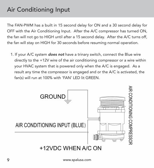
The FAN-PWM has a built in 15 second delay for ON and a 30 second delay for
OFF with the Air Conditioning Input. After the A/C compressor has turned ON,
the fan will not go to HIGH until after a 15 second delay. After the A/C turns off,
the fan will stay on HIGH for 30 seconds before resuming normal operation.
1. If your A/C system does not have a trinary switch, connect the Blue wire
directly to the +12V wire of the air conditioning compressor or a wire within
your HVAC system that is powered only when the A/C is engaged. As a
result any time the compressor is engaged and or the A/C is activated, the
fan(s) will run at 100% with ‘FAN’ LED lit GREEN.
www.spalusa.com 10
Air Conditioning Input(continued)
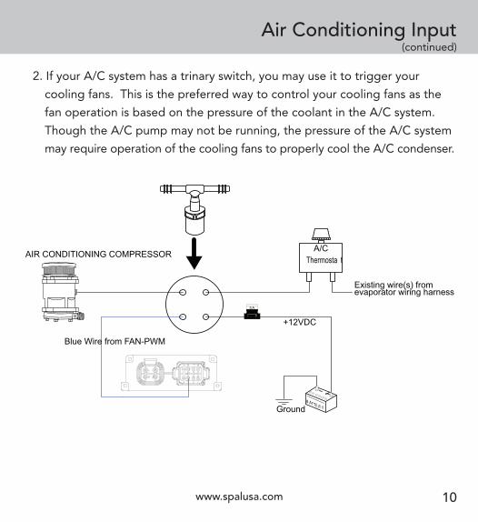
2. If your A/C system has a trinary switch, you may use it to trigger your
cooling fans. This is the preferred way to control your cooling fans as the
fan operation is based on the pressure of the coolant in the A/C system.
Though the A/C pump may not be running, the pressure of the A/C system
may require operation of the cooling fans to properly cool the A/C condenser.
AIR CONDITIONING COMPRESSOR
Blue Wire from FAN-PWM
A/CThermosta t
Existing wire(s) fromevaporator wiring harness
YTB A TE RGround
+12VDCFUSE
5A
A/C TRINARY DIAGRAM

Programming
ENTR PRG STAT FAN
‘Stat’ LED (Green):• On when FAN-PWM is powered from the ignition input. Fan(s) are not on.
• Blinking indicates an error code. See page 21 for error codes.
3 Color ‘Fan’ LED:• RED: High temperature setting has been reached.
• Fan(s) run at High speed.
• AMBER: Low temperature setting has been reached.
• Fan starts at half-speed and increases until High temperature setting is
reached.
• GREEN: Indicates Air Conditioning has been powered ON.
• Fan(s) run at full speed.
www.spalusa.com11

www.spalusa.com 12
When programming the FAN-PWM the fan will turn off automatically to allow
quicker warm-up of coolant temperature. If at anytime you enter programming
mode by mistake, repeatedly press the PRG button until the unit returns to
normal status.
1. Press and Hold down PRG button for 5 seconds.
2. Fan will stop running and the ‘FAN’ LED will be slowly blinking AMBER.
3. Warm engine up to desired LOW temperature and press ENTR button
to program LOW.
4. The ‘STAT’ LED will blink once and the ‘FAN’ LED will turn RED and be
blinking slowly.
5. Warm engine up to desired HIGH temperature and press ENTR button
to set HIGH.
6. The ‘STAT’ LED will blink once then ‘FAN’ LED will turn GREEN and be
blinking slowly.
7. Press the PRG button once to EXIT programming.
Programming(continued)
Setting Both The Low & High Temperature
www.spalusa.com13
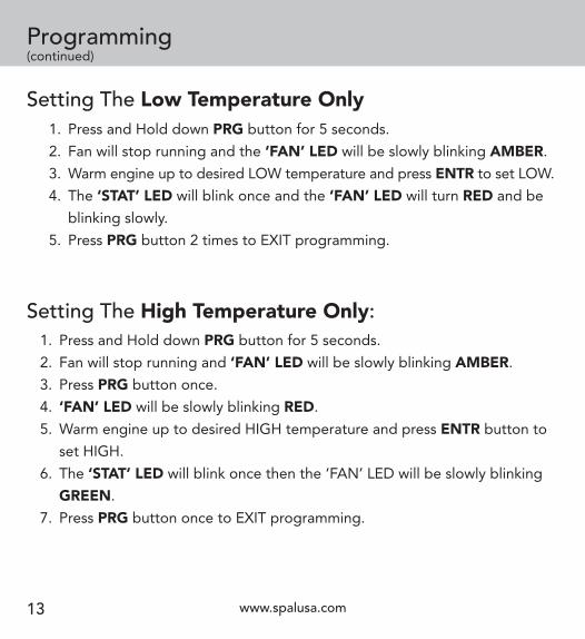
Programming(continued)
1. Press and Hold down PRG button for 5 seconds.
2. Fan will stop running and ‘FAN’ LED will be slowly blinking AMBER.
3. Press PRG button once.
4. ‘FAN’ LED will be slowly blinking RED.
5. Warm engine up to desired HIGH temperature and press ENTR button to
set HIGH.
6. The ‘STAT’ LED will blink once then the ‘FAN’ LED will be slowly blinking
GREEN.
7. Press PRG button once to EXIT programming.
Setting The High Temperature Only:
Setting The Low Temperature Only 1. Press and Hold down PRG button for 5 seconds.
2. Fan will stop running and the ‘FAN’ LED will be slowly blinking AMBER.
3. Warm engine up to desired LOW temperature and press ENTR to set LOW.
4. The ‘STAT’ LED will blink once and the ‘FAN’ LED will turn RED and be
blinking slowly.
5. Press PRG button 2 times to EXIT programming.
www.spalusa.com 14
Programming(continued)
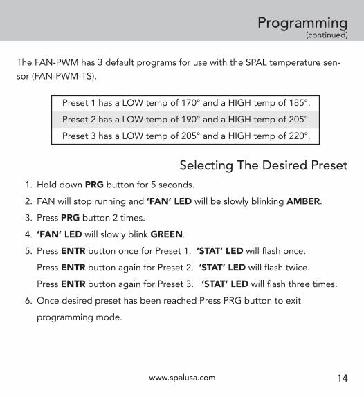
The FAN-PWM has 3 default programs for use with the SPAL temperature sen-
sor (FAN-PWM-TS).
Selecting The Desired Preset
1. Hold down PRG button for 5 seconds.
2. FAN will stop running and ‘FAN’ LED will be slowly blinking AMBER.
3. Press PRG button 2 times.
4. ‘FAN’ LED will slowly blink GREEN.
5. Press ENTR button once for Preset 1. ‘STAT’ LED will flash once.
Press ENTR button again for Preset 2. ‘STAT’ LED will flash twice.
Press ENTR button again for Preset 3. ‘STAT’ LED will flash three times.
6. Once desired preset has been reached Press PRG button to exit
programming mode.
Preset 1 has a LOW temp of 170° and a HIGH temp of 185°.
Preset 2 has a LOW temp of 190° and a HIGH temp of 205°.
Preset 3 has a LOW temp of 205° and a HIGH temp of 220°.
www.spalusa.com15
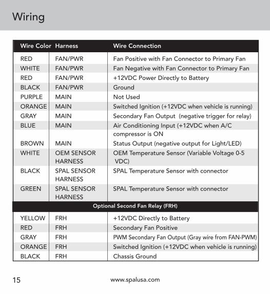
Wiring
Wire Color Harness Wire Connection
RED FAN/PWR Fan Positive with Fan Connector to Primary Fan
WHITE FAN/PWR Fan Negative with Fan Connector to Primary Fan
RED FAN/PWR +12VDC Power Directly to Battery
BLACK FAN/PWR Ground
PURPLE MAIN Not Used
ORANGE MAIN Switched Ignition (+12VDC when vehicle is running)
GRAY MAIN Secondary Fan Output (negative trigger for relay)
BLUE MAIN Air Conditioning Input (+12VDC when A/C compressor is ON
BROWN MAIN Status Output (negative output for Light/LED)
WHITE OEM SENSOR OEM Temperature Sensor (Variable Voltage 0-5 HARNESS VDC)
BLACK SPAL SENSOR SPAL Temperature Sensor with connector HARNESS
GREEN SPAL SENSOR SPAL Temperature Sensor with connector HARNESS
YELLOW FRH +12VDC Directly to Battery
RED FRH Secondary Fan Positive
GRAY FRH PWM Secondary Fan Output (Gray wire from FAN-PWM)
ORANGE FRH Switched Ignition (+12VDC when vehicle is running)
BLACK FRH Chassis Ground
Optional Second Fan Relay (FRH)

www.spalusa.com 16
Wiring(continued)
OEM TEMP SENSOR (WHITE)
VARIABLE VOLTAGE +
GROUND
SINGLE FAN OEM SENSOR
YTBA TE R
FUSE
GROUND(BLACK)
+12VDC (RED)
MAX. 30 AMP FUSEFAN/PWR HARNESS
CB
AIR CONDITIONING INPUT (BLUE) SEE PAGE 9
STATUS OUTPUT (BROWN) SEE PAGE 8
SWITCHED IGNITION (ORANGE)
(GRAY) NOT USED
MAIN HARNESS
(PURPLE) NOT USED
GROUND (BLACK)
Single Fan OEM Sensor

www.spalusa.com17
Wiring(continued) SINGLE FAN SPAL SENSOR
YTBA TE R
FUSE
GROUND(BLACK)
+12VDC (RED)
MAX. 30 AMP FUSEFAN/PWR HARNESS
CB
AIR CONDITIONING INPUT (BLUE) SEE PAGE 9
STATUS OUTPUT (BROWN) SEE PAGE 8
SWITCHED IGNITION (ORANGE)
(GRAY) NOT USED
MAIN HARNESS
(PURPLE) NOT USED
SPAL TEMP SENSOR HARNESS
SPAL SENSOR
GROUND (BLACK)
Single Fan SPAL Sensor
www.spalusa.com 18
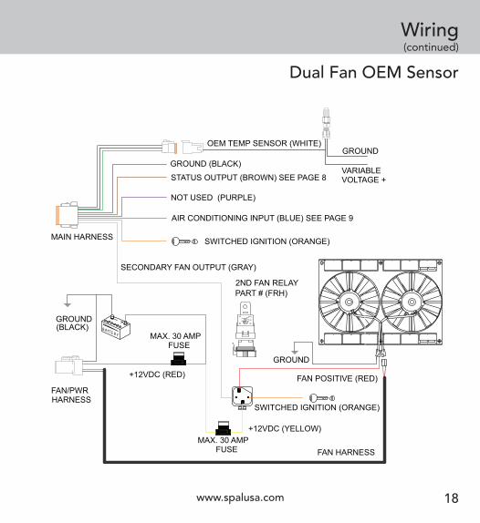
Wiring(continued)
CB
FAN POSITIVE (RED)
86
87
87a
85
30
YTBA TE R
FUSE
AIR CONDITIONING INPUT (BLUE) SEE PAGE 9
GROUND
GROUND
STATUS OUTPUT (BROWN) SEE PAGE 8
SWITCHED IGNITION (ORANGE)
(BLACK)
+12VDC (RED)
FAN HARNESS
SECONDARY FAN OUTPUT (GRAY)
SWITCHED IGNITION (ORANGE)
+12VDC (YELLOW)
2ND FAN RELAYPART # (FRH)
MAX. 30 AMP FUSE
MAX. 30 AMP FUSE
NOT USED (PURPLE)
OEM TEMP SENSOR (WHITE)
VARIABLE VOLTAGE +
GROUND
DUAL FAN OEM SENSOR
MAIN HARNESS
FAN/PWR HARNESS
FUSE
GROUND (BLACK)
Dual Fan OEM Sensor

www.spalusa.com19
Wiring(continued)
CB
FAN POSITIVE (RED)
86
87
87a
85
30
YTBA TE R
FUSE
AIR CONDITIONING INPUT (BLUE) SEE PAGE 9
GROUND
GROUND
STATUS OUTPUT (BROWN) SEE PAGE 8
SWITCHED IGNITION (ORANGE)
(BLACK)
+12VDC (RED)
FAN HARNESS
SECONDARY FAN OUTPUT (GRAY)
SWITCHED IGNITION (ORANGE)
+12VDC (YELLOW)
2ND FAN RELAYPART # (FRH)
MAX. 30 AMP FUSE
MAX. 30 AMP FUSE
NOT USED (PURPLE)
DUAL FAN SPAL SENSOR
MAIN HARNESS
FAN/PWR HARNESS
FUSE
SPAL TEMP SENSOR HARNESS
SPAL SENSOR
GROUND (BLACK)
Dual Fan SPAL Sensor

www.spalusa.com 20
Manual Fan Override Switch
This will allow your cooling fan to run anytime the override switch is ON.
WARNING: There is a 15 second delay after you flip the switch ON and a 30 sec-
ond delay after you flip the switch OFF. After you turn the switch ON the FAN(s)
will go to Full speed after the 15 second delay. The FAN(s) will stay on high until
the 30 second delay is complete. If the switch is turned ON and OFF repeatedly
the delay will restart after the last time the switch was turned ON or OFF.
**SPAL USA suggests this override switch also trigger the electric water pump
relay. This will allow a single override switch to control both the fan and elec-
tric water pump.**
Note: 1. The fan will continue to run indefinitely if the switch is not shut off.
2. When running for extended periods of time, the voltage should be
monitored as to not overly discharge the vehicle’s battery.
YTBA TE R
BLUE A/C INPUT WIRE +12VDC
TO BATTERY +12VDC
MANUAL FAN OVERRIDE SWITCH
Troubleshooting
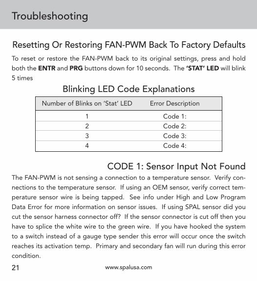
To reset or restore the FAN-PWM back to its original settings, press and hold
both the ENTR and PRG buttons down for 10 seconds. The ‘STAT’ LED will blink
5 times
Resetting Or Restoring FAN-PWM Back To Factory Defaults
Number of Blinks on ‘Stat’ LED
1
2
3
4
Blinking LED Code Explanations
CODE 1: Sensor Input Not FoundThe FAN-PWM is not sensing a connection to a temperature sensor. Verify con-
nections to the temperature sensor. If using an OEM sensor, verify correct tem-
perature sensor wire is being tapped. See info under High and Low Program
Data Error for more information on sensor issues. If using SPAL sensor did you
cut the sensor harness connector off? If the sensor connector is cut off then you
have to splice the white wire to the green wire. If you have hooked the system
to a switch instead of a gauge type sender this error will occur once the switch
reaches its activation temp. Primary and secondary fan will run during this error
condition.
www.spalusa.com21
Error Description
Code 1:
Code 2:
Code 3:
Code 4:
www.spalusa.com 22
Troubleshooting(continued)
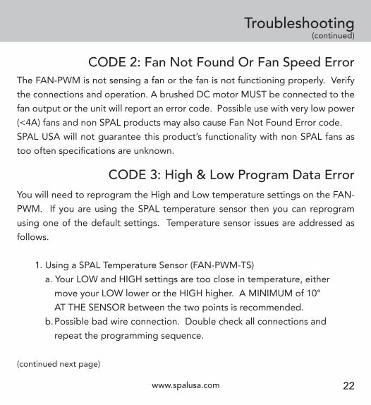
CODE 2: Fan Not Found Or Fan Speed ErrorThe FAN-PWM is not sensing a fan or the fan is not functioning properly. Verify
the connections and operation. A brushed DC motor MUST be connected to the
fan output or the unit will report an error code. Possible use with very low power
(<4A) fans and non SPAL products may also cause Fan Not Found Error code.
SPAL USA will not guarantee this product’s functionality with non SPAL fans as
too often specifications are unknown.
CODE 3: High & Low Program Data ErrorYou will need to reprogram the High and Low temperature settings on the FAN-
PWM. If you are using the SPAL temperature sensor then you can reprogram
using one of the default settings. Temperature sensor issues are addressed as
follows.
1. Using a SPAL Temperature Sensor (FAN-PWM-TS)
a. Your LOW and HIGH settings are too close in temperature, either
move your LOW lower or the HIGH higher. A MINIMUM of 10°
AT THE SENSOR between the two points is recommended.
b. Possible bad wire connection. Double check all connections and
repeat the programming sequence.
(continued next page)
Troubleshooting(continued)
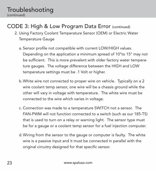
CODE 3: High & Low Program Data Error (continued)
2. Using Factory Coolant Temperature Sensor (OEM) or Electric Water
Temperature Gauge
a. Sensor profile not compatible with current LOW/HIGH values.
Depending on the application a minimum spread of 10°to 15° may not
be sufficient. This is more prevalent with older factory water tempera-
ture gauges. The voltage difference between the HIGH and LOW
temperature settings must be .1 Volt or higher.
b. White wire not connected to proper wire on vehicle. Typically on a 2
wire coolant temp sensor, one wire will be a chassis ground while the
other will vary in voltage with temperature. The white wire must be
connected to the wire which varies in voltage.
c. Connection was made to a temperature SWITCH not a sensor. The
FAN-PWM will not function connected to a switch (such as our 185-TS)
that is used to turn on a relay or warning light. The sensor type must
be for a gauge or a coolant temp sensor for a fuel injection computer.
d. Wiring from the sensor to the gauge or computer is faulty. The white
wire is a passive input and it must be connected in parallel with the
original circuitry designed for that specific sensor.
www.spalusa.com23

www.spalusa.com 24
Troubleshooting(continued)
e. There are some 2 stage computer sensors which vary in voltage in 2
steps. These sensors drop in voltage until they reach a certain
temperature (example 200°) then the engine raises the power level
suddenly to have another similar drop in voltage. You might be able to
program the FAN-PWM to work within ONE of these stages. But as a
side effect, it will work also in the other stage which means the fan may
operate when not necessarily needed. For complete proper operation
in this case you will need to use a SPAL temperature sensor.
CODE 3: High & Low Program Data Error (continued)
CODE 4: Module Over Current ErrorOver current protection means that the output will SHUT DOWN if the mea-
sured fan continuous run current increases above 30A for extended periods. If
running a fan that is approaching this amount of current draw (>25A), SPAL USA
recommends that the installation also include a status light so the operator will
be aware of the fan status.
FAQ
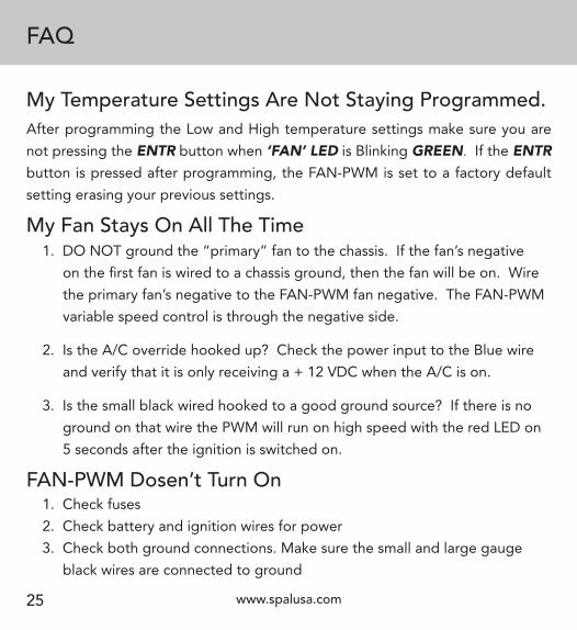
After programming the Low and High temperature settings make sure you are
not pressing the ENTR button when ‘FAN’ LED is Blinking GREEN. If the ENTR button is pressed after programming, the FAN-PWM is set to a factory default
setting erasing your previous settings.
My Temperature Settings Are Not Staying Programmed.
My Fan Stays On All The Time
FAN-PWM Dosen’t Turn On 1. Check fuses
2. Check battery and ignition wires for power
3. Check both ground connections. Make sure the small and large gauge
black wires are connected to ground
www.spalusa.com25
1. DO NOT ground the “primary” fan to the chassis. If the fan’s negative
on the first fan is wired to a chassis ground, then the fan will be on. Wire
the primary fan’s negative to the FAN-PWM fan negative. The FAN-PWM
variable speed control is through the negative side.
2. Is the A/C override hooked up? Check the power input to the Blue wire
and verify that it is only receiving a + 12 VDC when the A/C is on.
3. Is the small black wired hooked to a good ground source? If there is no
ground on that wire the PWM will run on high speed with the red LED on
5 seconds after the ignition is switched on.
www.spalusa.com 26
FAQ(continued)
1. Check relay wiring
2. Confirm ground signal from FAN-PWM on Gray wire when on High
3. Verify fan is working properly by grounding the gray wire from the relay
and turning the ignition on, fan should run at this time.
Second Fan Will Not Turn On
1. After the A/C or manual switch is turned on, there is a 15 second delay
before the FAN-PWM will override into High Mode.
2. Verify there is + 12 Volts going to the Blue wire when A/C or switch is
turned on.
Fan Does Not Go Into High Mode Immediately After The A/C or Manual Override Is Turned On
Fans Stays In High Mode After Turning Off The A/C Or Switch
1. After the A/C or switch is turned off, there is a 30 second delay before the
FAN-PWM will resume its normal variable speed operation.
2. Verify there is no power present on the Blue wire when the A/C or switch
is turned off.
For optional wiring diagrams, including 2-speed fans - visit www.spalusa.com,
or contact tech support at 1-800-454-7725 - email [email protected]

03_08-109-FanPWM
1s
SPAL Limited Warranty
SPAL USA warrants this product to be free from defects in material and work-
manship for a period of eighteen (18) months from the date of sale of the origi-
nal purchaser. SPAL USA will repair this product free of charge if, in the judg-
ment of SPAL USA it has been proven defective within the warranty period. The
product should be returned, at the customer expense, to the location of original
purchase. This warranty does not cover any expenses incurred in the removal
and/or reinstallation of the product.
This warranty does not apply to any product damaged by improper installation,
misuse, abuse, improper line voltage, fire, flood, lightning, or other acts of God,
or a product altered or repaired by anyone other than SPAL USA.
This warranty is in lieu of other warranties, expressed or implied, including any
implied warranty of merchantability. No person is authorized to assume for
SPAL USA any other liability concerning the sale of this product.
*IMPORTANT - KEEP YOUR RECEIPT WITH THIS WARRANTY STATEMENT!
If you have other questions about the installation of the FAN-PWM contact
SPAL USA tech support at 1-800-454-7725 or email [email protected].
Additional information and updates can be found on at www.spalusa.com.
www.spalusa.com


