634
DESCRIPTIONS B-63522EN/03 FANUC Series 16*/160*/160*s-MODEL B FANUC Series 18*/180*/180*s-MODEL B FANUC Series 21*/210*/210*s-MODEL B FANUC Series 20*-MODEL B

DESCRIPTIONS
B-63522EN/03
FANUC Series 16*/160*/160*s-MODEL B
FANUC Series 18*/180*/180*s-MODEL B
FANUC Series 21*/210*/210*s-MODEL B
FANUC Series 20*-MODEL B

• No part of this manual may be reproduced in any form. • All specifications and designs are subject to change without notice. The export of this product is subject to the authorization of the government of the country from where the product is exported. In this manual we have tried as much as possible to describe all the various matters. However, we cannot describe all the matters which must not be done, or which cannot be done, because there are so many possibilities. Therefore, matters which are not especially described as possible in this manual should be regarded as ”impossible”. This manual contains the program names or device names of other companies, some of which are registered trademarks of respective owners. However, these names are not followed by or in the main body.
s–1
SAFETY PRECAUTIONS
This section describes the safety precautions related to the use of CNC units. It is essential that these precautionsbe observed by users to ensure the safe operation of machines equipped with a CNC unit (all descriptions in thissection assume this configuration). Note that some precautions are related only to specific functions, and thusmay not be applicable to certain CNC units.Users must also observe the safety precautions related to the machine, as described in the relevant manual suppliedby the machine tool builder. Before attempting to operate the machine or create a program to control the operationof the machine, the operator must become fully familiar with the contents of this manual and relevant manualsupplied by the machine tool builder.
Contents
1. DEFINITION OF WARNING, CAUTION, AND NOTE s–2. . . . . . . . . . . . . . . . . . . . . . .
2. GENERAL WARNINGS AND CAUTIONS s–3. . . . . . . . . . . . . . . . . . . . . . . . . . . . . . . .
3. WARNINGS AND CAUTIONS RELATED TO PROGRAMMING s–5. . . . . . . . . . . . .
4. WARNINGS AND CAUTIONS RELATED TO HANDLING s–7. . . . . . . . . . . . . . . . . . .
5. WARNINGS RELATED TO DAILY MAINTENANCE s–9. . . . . . . . . . . . . . . . . . . . . . . .

SAFETY PRECAUTIONS B–63522EN/03
s–2
1 DEFINITION OF WARNING, CAUTION, AND NOTE
This manual includes safety precautions for protecting the user and preventing damage to themachine. Precautions are classified into Warning and Caution according to their bearing on safety.Also, supplementary information is described as a Note. Read the Warning, Caution, and Notethoroughly before attempting to use the machine.
WARNING
Applied when there is a danger of the user being injured or when there is a danger of both the userbeing injured and the equipment being damaged if the approved procedure is not observed.
CAUTION
Applied when there is a danger of the equipment being damaged, if the approved procedure is notobserved.
NOTE
The Note is used to indicate supplementary information other than Warning and Caution.
� Read this manual carefully, and store it in a safe place.
B–63522EN/03 SAFETY PRECAUTIONS
s–3
2 GENERAL WARNINGS AND CAUTIONS
WARNING
1. Never attempt to machine a workpiece without first checking the operation of the machine.Before starting a production run, ensure that the machine is operating correctly by performinga trial run using, for example, the single block, feedrate override, or machine lock function orby operating the machine with neither a tool nor workpiece mounted. Failure to confirm thecorrect operation of the machine may result in the machine behaving unexpectedly, possiblycausing damage to the workpiece and/or machine itself, or injury to the user.
2. Before operating the machine, thoroughly check the entered data.Operating the machine with incorrectly specified data may result in the machine behavingunexpectedly, possibly causing damage to the workpiece and/or machine itself, or injury to theuser.
3. Ensure that the specified feedrate is appropriate for the intended operation. Generally, for eachmachine, there is a maximum allowable feedrate. The appropriate feedrate varies with theintended operation. Refer to the manual provided with the machine to determine the maximumallowable feedrate. If a machine is run at other than the correct speed, it may behaveunexpectedly, possibly causing damage to the workpiece and/or machine itself, or injury to theuser.
4. When using a tool compensation function, thoroughly check the direction and amount ofcompensation. Operating the machine with incorrectly specified data may result in the machine behavingunexpectedly, possibly causing damage to the workpiece and/or machine itself, or injury to theuser.
5. The parameters for the CNC and PMC are factory–set. Usually, there is not need to change them.When, however, there is not alternative other than to change a parameter, ensure that you fullyunderstand the function of the parameter before making any change.Failure to set a parameter correctly may result in the machine behaving unexpectedly, possiblycausing damage to the workpiece and/or machine itself, or injury to the user.
6. Immediately after switching on the power, do not touch any of the keys on the MDI panel untilthe position display or alarm screen appears on the CNC unit.Some of the keys on the MDI panel are dedicated to maintenance or other special operations.Pressing any of these keys may place the CNC unit in other than its normal state. Starting themachine in this state may cause it to behave unexpectedly.
7. The operator’s manual and programming manual supplied with a CNC unit provide an overalldescription of the machine’s functions, including any optional functions. Note that the optionalfunctions will vary from one machine model to another. Therefore, some functions describedin the manuals may not actually be available for a particular model. Check the specification ofthe machine if in doubt.

SAFETY PRECAUTIONS B–63522EN/03
s–4
WARNING
8. Some functions may have been implemented at the request of the machine–tool builder. Whenusing such functions, refer to the manual supplied by the machine–tool builder for details of theiruse and any related cautions.
CAUTION
1. Do not remove the internal parts, including the ATA card and compact flash card, from withinthe CNC.
NOTE
Programs, parameters, and macro variables are stored in nonvolatile memory in the CNC unit.Usually, they are retained even if the power is turned off. Such data may be deleted inadvertently,however, or it may prove necessary to delete all data from nonvolatile memory as part of errorrecovery.To guard against the occurrence of the above, and assure quick restoration of deleted data, backupall vital data, and keep the backup copy in a safe place.

B–63522EN/03 SAFETY PRECAUTIONS
s–5
3 WARNINGS AND CAUTIONS RELATED TOPROGRAMMING
This section covers the major safety precautions related to programming. Before attempting toperform programming, read the supplied operator’s manual and programming manual carefullysuch that you are fully familiar with their contents.
WARNING
1. Coordinate system setting
If a coordinate system is established incorrectly, the machine may behave unexpectedly as aresult of the program issuing an otherwise valid move command.Such an unexpected operation may damage the tool, the machine itself, the workpiece, or causeinjury to the user.
2. Positioning by nonlinear interpolation
When performing positioning by nonlinear interpolation (positioning by nonlinear movementbetween the start and end points), the tool path must be carefully confirmed before performingprogramming.Positioning involves rapid traverse. If the tool collides with the workpiece, it may damage thetool, the machine itself, the workpiece, or cause injury to the user.
3. Function involving a rotation axis
When programming polar coordinate interpolation or normal–direction (perpendicular) control,pay careful attention to the speed of the rotation axis. Incorrect programming may result in therotation axis speed becoming excessively high, such that centrifugal force causes the chuck tolose its grip on the workpiece if the latter is not mounted securely.Such mishap is likely to damage the tool, the machine itself, the workpiece, or cause injury tothe user.
4. Inch/metric conversion
Switching between inch and metric inputs does not convert the measurement units of data suchas the workpiece origin offset, parameter, and current position. Before starting the machine,therefore, determine which measurement units are being used. Attempting to perform anoperation with invalid data specified may damage the tool, the machine itself, the workpiece, orcause injury to the user.
5. Constant surface speed control
When an axis subject to constant surface speed control approaches the origin of the workpiececoordinate system, the spindle speed may become excessively high. Therefore, it is necessaryto specify a maximum allowable speed. Specifying the maximum allowable speed incorrectlymay damage the tool, the machine itself, the workpiece, or cause injury to the user.

SAFETY PRECAUTIONS B–63522EN/03
s–6
WARNING
6. Stroke check
After switching on the power, perform a manual reference position return as required. Strokecheck is not possible before manual reference position return is performed. Note that when strokecheck is disabled, an alarm is not issued even if a stroke limit is exceeded, possibly damagingthe tool, the machine itself, the workpiece, or causing injury to the user.
7. Tool post interference check
A tool post interference check is performed based on the tool data specified during automaticoperation. If the tool specification does not match the tool actually being used, the interferencecheck cannot be made correctly, possibly damaging the tool or the machine itself, or causinginjury to the user.After switching on the power, or after selecting a tool post manually, always start automaticoperation and specify the tool number of the tool to be used.
8. Absolute/incremental mode
If a program created with absolute values is run in incremental mode, or vice versa, the machinemay behave unexpectedly.
9. Plane selection
If an incorrect plane is specified for circular interpolation, helical interpolation, or a canned cycle,the machine may behave unexpectedly. Refer to the descriptions of the respective functions fordetails.
10. Torque limit skip
Before attempting a torque limit skip, apply the torque limit. If a torque limit skip is specifiedwithout the torque limit actually being applied, a move command will be executed withoutperforming a skip.
11. Programmable mirror image
Note that programmed operations vary considerably when a programmable mirror image isenabled.
12. Compensation function
If a command based on the machine coordinate system or a reference position return commandis issued in compensation function mode, compensation is temporarily canceled, resulting in theunexpected behavior of the machine.Before issuing any of the above commands, therefore, always cancel compensation functionmode.

B–63522EN/03 SAFETY PRECAUTIONS
s–7
4 WARNINGS AND CAUTIONS RELATED TO HANDLING
This section presents safety precautions related to the handling of machine tools. Before attemptingto operate your machine, read the supplied operator’s manual and programming manual carefully,such that you are fully familiar with their contents.
WARNING
1. Manual operation
When operating the machine manually, determine the current position of the tool and workpiece,and ensure that the movement axis, direction, and feedrate have been specified correctly.Incorrect operation of the machine may damage the tool, the machine itself, the workpiece, orcause injury to the operator.
2. Manual reference position return
After switching on the power, perform manual reference position return as required. If themachine is operated without first performing manual reference position return, it may behaveunexpectedly. Stroke check is not possible before manual reference position return is performed.An unexpected operation of the machine may damage the tool, the machine itself, the workpiece,or cause injury to the user.
3. Manual numeric command
When issuing a manual numeric command, determine the current position of the tool andworkpiece, and ensure that the movement axis, direction, and command have been specifiedcorrectly, and that the entered values are valid.Attempting to operate the machine with an invalid command specified may damage the tool, themachine itself, the workpiece, or cause injury to the operator.
4. Manual handle feed
In manual handle feed, rotating the handle with a large scale factor, such as 100, applied causesthe tool and table to move rapidly. Careless handling may damage the tool and/or machine, orcause injury to the user.
5. Disabled override
If override is disabled (according to the specification in a macro variable) during threading, rigidtapping, or other tapping, the speed cannot be predicted, possibly damaging the tool, the machineitself, the workpiece, or causing injury to the operator.
6. Origin/preset operation
Basically, never attempt an origin/preset operation when the machine is operating under thecontrol of a program. Otherwise, the machine may behave unexpectedly, possibly damaging thetool, the machine itself, the tool, or causing injury to the user.

SAFETY PRECAUTIONS B–63522EN/03
s–8
WARNING
7. Workpiece coordinate system shift
Manual intervention, machine lock, or mirror imaging may shift the workpiece coordinatesystem. Before attempting to operate the machine under the control of a program, confirm thecoordinate system carefully.If the machine is operated under the control of a program without making allowances for any shiftin the workpiece coordinate system, the machine may behave unexpectedly, possibly damagingthe tool, the machine itself, the workpiece, or causing injury to the operator.
8. Software operator’s panel and menu switches
Using the software operator’s panel and menu switches, in combination with the MDI panel, itis possible to specify operations not supported by the machine operator’s panel, such as modechange, override value change, and jog feed commands.Note, however, that if the MDI panel keys are operated inadvertently, the machine may behaveunexpectedly, possibly damaging the tool, the machine itself, the workpiece, or causing injuryto the user.
9. Manual intervention
If manual intervention is performed during programmed operation of the machine, the tool pathmay vary when the machine is restarted. Before restarting the machine after manual intervention,therefore, confirm the settings of the manual absolute switches, parameters, andabsolute/incremental command mode.
10. Feed hold, override, and single block
The feed hold, feedrate override, and single block functions can be disabled using custom macrosystem variable #3004. Be careful when operating the machine in this case.
11. Dry run
Usually, a dry run is used to confirm the operation of the machine. During a dry run, the machineoperates at dry run speed, which differs from the corresponding programmed feedrate. Note thatthe dry run speed may sometimes be higher than the programmed feed rate.
12. Cutter and tool nose radius compensation in MDI mode
Pay careful attention to a tool path specified by a command in MDI mode, because cutter or toolnose radius compensation is not applied. When a command is entered from the MDI to interruptin automatic operation in cutter or tool nose radius compensation mode, pay particular attentionto the tool path when automatic operation is subsequently resumed. Refer to the descriptions ofthe corresponding functions for details.
13. Program editing
If the machine is stopped, after which the machining program is edited (modification, insertion,or deletion), the machine may behave unexpectedly if machining is resumed under the controlof that program. Basically, do not modify, insert, or delete commands from a machining programwhile it is in use.

B–63522EN/03 SAFETY PRECAUTIONS
s–9
5 WARNINGS RELATED TO DAILY MAINTENANCE
WARNING
1. Memory backup battery replacement
When replacing the memory backup batteries, keep the power to the machine (CNC) turned on,and apply an emergency stop to the machine. Because this work is performed with the poweron and the cabinet open, only those personnel who have received approved safety andmaintenance training may perform this work.When replacing the batteries, be careful not to touch the high–voltage circuits (marked andfitted with an insulating cover).Touching the uncovered high–voltage circuits presents an extremely dangerous electric shockhazard.
NOTE
The CNC uses batteries to preserve the contents of its memory, because it must retain data such asprograms, offsets, and parameters even while external power is not applied.If the battery voltage drops, a low battery voltage alarm is displayed on the machine operator’s panelor screen.When a low battery voltage alarm is displayed, replace the batteries within a week. Otherwise, thecontents of the CNC’s memory will be lost.Refer to the maintenance section of the operator’s manual or programming manual for details of thebattery replacement procedure.
SAFETY PRECAUTIONS B–63522EN/03
s–10
WARNING
2. Absolute pulse coder battery replacement
When replacing the memory backup batteries, keep the power to the machine (CNC) turned on,and apply an emergency stop to the machine. Because this work is performed with the poweron and the cabinet open, only those personnel who have received approved safety andmaintenance training may perform this work.When replacing the batteries, be careful not to touch the high–voltage circuits (marked andfitted with an insulating cover).Touching the uncovered high–voltage circuits presents an extremely dangerous electric shockhazard.
NOTE
The absolute pulse coder uses batteries to preserve its absolute position.If the battery voltage drops, a low battery voltage alarm is displayed on the machine operator’s panelor screen.When a low battery voltage alarm is displayed, replace the batteries within a week. Otherwise, theabsolute position data held by the pulse coder will be lost.Refer to FANUC SERVO AMPLIFIER αi series MAINTENANCE MANUAL and FANUCSERVO AMPLIFIER βi series MAINTENANCE MANUAL for details of the battery replacementprocedure.
B–63522EN/03 SAFETY PRECAUTIONS
s–11
WARNING
3. Fuse replacement
For some units, the chapter covering daily maintenance in the operator’s manual or programmingmanual describes the fuse replacement procedure.Before replacing a blown fuse, however, it is necessary to locate and remove the cause of theblown fuse.For this reason, only those personnel who have received approved safety and maintenancetraining may perform this work.When replacing a fuse with the cabinet open, be careful not to touch the high–voltage circuits(marked and fitted with an insulating cover).Touching an uncovered high–voltage circuit presents an extremely dangerous electric shockhazard.


B–63522EN/03 Table of Contents
c–1
SAFETY PRECAUTIONS s–1. . . . . . . . . . . . . . . . . . . . . . . . . . . . . . . . . . . . . . . . . . . . . . . . . .
I. GENERAL
1. GENERAL 3. . . . . . . . . . . . . . . . . . . . . . . . . . . . . . . . . . . . . . . . . . . . . . . . . . . . . . . . . . . .
2. LIST OF SPECIFICATIONS 8. . . . . . . . . . . . . . . . . . . . . . . . . . . . . . . . . . . . . . . . . . . . .
II. NC FUNCTION
PREFACE 33. . . . . . . . . . . . . . . . . . . . . . . . . . . . . . . . . . . . . . . . . . . . . . . . . . . . . . . . . . . . . . . .
1. CONTROLLED AXES 34. . . . . . . . . . . . . . . . . . . . . . . . . . . . . . . . . . . . . . . . . . . . . . . . . . 1.1 NUMBER OF THE ALL CONTROLLED AXES 35. . . . . . . . . . . . . . . . . . . . . . . . . . . . . . . . . . . . . . .
1.2 MACHINE CONTROLLED AXES 36. . . . . . . . . . . . . . . . . . . . . . . . . . . . . . . . . . . . . . . . . . . . . . . . . . 1.2.1 Number of Controlled Paths 36. . . . . . . . . . . . . . . . . . . . . . . . . . . . . . . . . . . . . . . . . . . . . . . . . . . . . . . . . 1.2.2 Number of Basic Controlled Axes 36. . . . . . . . . . . . . . . . . . . . . . . . . . . . . . . . . . . . . . . . . . . . . . . . . . . . 1.2.3 Number of Basic Simultaneously Controlled Axes 36. . . . . . . . . . . . . . . . . . . . . . . . . . . . . . . . . . . . . . . . 1.2.4 Number of Controlled Axes Expanded (All) 36. . . . . . . . . . . . . . . . . . . . . . . . . . . . . . . . . . . . . . . . . . . . 1.2.5 Number of Simultaneously Controlled Axes Expanded (All) 37. . . . . . . . . . . . . . . . . . . . . . . . . . . . . . . . 1.2.6 Axis Control by PMC 37. . . . . . . . . . . . . . . . . . . . . . . . . . . . . . . . . . . . . . . . . . . . . . . . . . . . . . . . . . . . . . 1.2.7 Cs Contour Control 37. . . . . . . . . . . . . . . . . . . . . . . . . . . . . . . . . . . . . . . . . . . . . . . . . . . . . . . . . . . . . . .
1.3 LOADER CONTROLLED AXES 38. . . . . . . . . . . . . . . . . . . . . . . . . . . . . . . . . . . . . . . . . . . . . . . . . . .
1.4 AXIS NAMES 38. . . . . . . . . . . . . . . . . . . . . . . . . . . . . . . . . . . . . . . . . . . . . . . . . . . . . . . . . . . . . . . . . . .
1.5 INCREMENT SYSTEM 39. . . . . . . . . . . . . . . . . . . . . . . . . . . . . . . . . . . . . . . . . . . . . . . . . . . . . . . . . . . 1.5.1 Input Unit (10 Times) 40. . . . . . . . . . . . . . . . . . . . . . . . . . . . . . . . . . . . . . . . . . . . . . . . . . . . . . . . . . . . . .
1.6 MAXIMUM STROKE 41. . . . . . . . . . . . . . . . . . . . . . . . . . . . . . . . . . . . . . . . . . . . . . . . . . . . . . . . . . . .
2. PREPARATORY FUNCTIONS 42. . . . . . . . . . . . . . . . . . . . . . . . . . . . . . . . . . . . . . . . . . . 2.1 T SERIES 43. . . . . . . . . . . . . . . . . . . . . . . . . . . . . . . . . . . . . . . . . . . . . . . . . . . . . . . . . . . . . . . . . . . . . .
2.2 M SERIES 46. . . . . . . . . . . . . . . . . . . . . . . . . . . . . . . . . . . . . . . . . . . . . . . . . . . . . . . . . . . . . . . . . . . . . .
3. INTERPOLATION FUNCTIONS 50. . . . . . . . . . . . . . . . . . . . . . . . . . . . . . . . . . . . . . . . . . 3.1 POSITIONING (G00) 51. . . . . . . . . . . . . . . . . . . . . . . . . . . . . . . . . . . . . . . . . . . . . . . . . . . . . . . . . . . . .
3.2 SINGLE DIRECTION POSITIONING (G60) (M series) 52. . . . . . . . . . . . . . . . . . . . . . . . . . . . . . . . .
3.3 LINEAR INTERPOLATION (G01) 53. . . . . . . . . . . . . . . . . . . . . . . . . . . . . . . . . . . . . . . . . . . . . . . . . .
3.4 CIRCULAR INTERPOLATION (G02, G03) 54. . . . . . . . . . . . . . . . . . . . . . . . . . . . . . . . . . . . . . . . . . .
3.5 HELICAL INTERPOLATION (G02, G03) 56. . . . . . . . . . . . . . . . . . . . . . . . . . . . . . . . . . . . . . . . . . . .
3.6 HELICAL INTERPOLATION B (G02, G03) (M series) 57. . . . . . . . . . . . . . . . . . . . . . . . . . . . . . . . . .
3.7 POLAR COORDINATE INTERPOLATION (G12.1, G13.1) 58. . . . . . . . . . . . . . . . . . . . . . . . . . . . . .
3.8 CYLINDRICAL INTERPOLATION (G07.1) 60. . . . . . . . . . . . . . . . . . . . . . . . . . . . . . . . . . . . . . . . . .
3.9 CYLINDRICAL INTERPOLATION CUTTING POINT COMPENSATION (G07.1) (M series) 62. .
3.10 INVOLUTE INTERPOLATION (G02.2, G03.2) (M series) 65. . . . . . . . . . . . . . . . . . . . . . . . . . . . . . . 3.10.1 Involute Interpolation Automatic Feedrate Control Function (M series) 66. . . . . . . . . . . . . . . . . . . . . . . .
3.11 EXPONENTIAL FUNCTION INTERPOLATION (G02.3, G03.3) (M series) 67. . . . . . . . . . . . . . . . .
3.12 SMOOTH INTERPOLATION (G05.1) (ONLY AT 1–PATH CONTROL) (M series) 69. . . . . . . . . . .
3.13 HYPOTHETICAL AXIS INTERPOLATION (G07) 70. . . . . . . . . . . . . . . . . . . . . . . . . . . . . . . . . . . . .

B–63522EN/03Table of Contents
c–2
3.14 SPIRAL INTERPOLATION, CONICAL INTERPOLATION (M series) 71. . . . . . . . . . . . . . . . . . . .
3.15 NURBS INTERPOLATION (G06.2) 73. . . . . . . . . . . . . . . . . . . . . . . . . . . . . . . . . . . . . . . . . . . . . . . . .
3.16 3–DIMENSIONAL CIRCULAR INTERPOLATION (G02.4 AND G03.4) 75. . . . . . . . . . . . . . . . . . .
4. THREAD CUTTING 76. . . . . . . . . . . . . . . . . . . . . . . . . . . . . . . . . . . . . . . . . . . . . . . . . . . . 4.1 EQUAL LEAD THREAD CUTTING (G33) (WITH G CODE SYSTEM A: G32) 77. . . . . . . . . . . . .
4.2 MULTIPLE–THREAD CUTTING (G33) (T series) 78. . . . . . . . . . . . . . . . . . . . . . . . . . . . . . . . . . . . .
4.3 VARIABLE LEAD THREAD CUTTING (G34) (T series) 78. . . . . . . . . . . . . . . . . . . . . . . . . . . . . . . .
4.4 CONTINUOUS THREAD CUTTING (T series) 79. . . . . . . . . . . . . . . . . . . . . . . . . . . . . . . . . . . . . . . .
4.5 CIRCULAR THREADING (G35, G36) (T series) 79. . . . . . . . . . . . . . . . . . . . . . . . . . . . . . . . . . . . . .
5. FEED FUNCTIONS 80. . . . . . . . . . . . . . . . . . . . . . . . . . . . . . . . . . . . . . . . . . . . . . . . . . . . . 5.1 RAPID TRAVERSE 81. . . . . . . . . . . . . . . . . . . . . . . . . . . . . . . . . . . . . . . . . . . . . . . . . . . . . . . . . . . . . .
5.2 CUTTING FEED RATE 82. . . . . . . . . . . . . . . . . . . . . . . . . . . . . . . . . . . . . . . . . . . . . . . . . . . . . . . . . . . 5.2.1 Tangential Speed Constant Control 82. . . . . . . . . . . . . . . . . . . . . . . . . . . . . . . . . . . . . . . . . . . . . . . . . . . . 5.2.2 Cutting Feed Rate Clamp 82. . . . . . . . . . . . . . . . . . . . . . . . . . . . . . . . . . . . . . . . . . . . . . . . . . . . . . . . . . . 5.2.3 Per Minute Feed (G94) (G98 for G–code System A) 82. . . . . . . . . . . . . . . . . . . . . . . . . . . . . . . . . . . . . . 5.2.4 Per Revolution Feed (G95) (G99 for G–code System A) 83. . . . . . . . . . . . . . . . . . . . . . . . . . . . . . . . . . . 5.2.5 Inverse Time Feed (G93) (M series) 83. . . . . . . . . . . . . . . . . . . . . . . . . . . . . . . . . . . . . . . . . . . . . . . . . . . 5.2.6 One–digit F Code Feed (M series) 83. . . . . . . . . . . . . . . . . . . . . . . . . . . . . . . . . . . . . . . . . . . . . . . . . . . .
5.3 OVERRIDE 84. . . . . . . . . . . . . . . . . . . . . . . . . . . . . . . . . . . . . . . . . . . . . . . . . . . . . . . . . . . . . . . . . . . . . 5.3.1 Feed Rate Override 84. . . . . . . . . . . . . . . . . . . . . . . . . . . . . . . . . . . . . . . . . . . . . . . . . . . . . . . . . . . . . . . . 5.3.2 Second Feed Rate Override 84. . . . . . . . . . . . . . . . . . . . . . . . . . . . . . . . . . . . . . . . . . . . . . . . . . . . . . . . . 5.3.3 Rapid Traverse Override 84. . . . . . . . . . . . . . . . . . . . . . . . . . . . . . . . . . . . . . . . . . . . . . . . . . . . . . . . . . . . 5.3.4 Override Cancel 84. . . . . . . . . . . . . . . . . . . . . . . . . . . . . . . . . . . . . . . . . . . . . . . . . . . . . . . . . . . . . . . . . . 5.3.5 Jog Override 84. . . . . . . . . . . . . . . . . . . . . . . . . . . . . . . . . . . . . . . . . . . . . . . . . . . . . . . . . . . . . . . . . . . . .
5.4 AUTOMATIC ACCELERATION/DECELERATION 85. . . . . . . . . . . . . . . . . . . . . . . . . . . . . . . . . . . .
5.5 RAPID TRAVERSE BELL–SHAPED ACCELERATION/DECELERATION 86. . . . . . . . . . . . . . . . .
5.6 LINEAR ACCELERATION/DECELERATION AFTER CUTTING FEED INTERPOLATION 87. .
5.7 BELL–SHAPED ACCELERATION/DECELERATION AFTER CUTTING FEED INTERPOLATION 88. . . . . . . . . . . . . . . . . . . . . . . . . . . . . . . . . . . . . . . . . . . . . . . . . . . . . . . . .
5.8 LINEAR ACCELERATION/DECELERATION BEFORE CUTTING FEED INTERPOLATION 89. . . . . . . . . . . . . . . . . . . . . . . . . . . . . . . . . . . . . . . . . . . . . . . . . . . . . . . . .
5.9 ERROR DETECTION (T series) 90. . . . . . . . . . . . . . . . . . . . . . . . . . . . . . . . . . . . . . . . . . . . . . . . . . . .
5.10 EXACT STOP (G09) (M series) 91. . . . . . . . . . . . . . . . . . . . . . . . . . . . . . . . . . . . . . . . . . . . . . . . . . . . .
5.11 EXACT STOP MODE (G61) (M series) 91. . . . . . . . . . . . . . . . . . . . . . . . . . . . . . . . . . . . . . . . . . . . . .
5.12 CUTTING MODE (G64) (M series) 91. . . . . . . . . . . . . . . . . . . . . . . . . . . . . . . . . . . . . . . . . . . . . . . . .
5.13 TAPPING MODE (G63) (M series) 91. . . . . . . . . . . . . . . . . . . . . . . . . . . . . . . . . . . . . . . . . . . . . . . . . .
5.14 AUTOMATIC CORNER OVERRIDE (G62) (M series) 91. . . . . . . . . . . . . . . . . . . . . . . . . . . . . . . . . .
5.15 DWELL (G04) 92. . . . . . . . . . . . . . . . . . . . . . . . . . . . . . . . . . . . . . . . . . . . . . . . . . . . . . . . . . . . . . . . . .
5.16 POSITIONING BY OPTIMUM ACCELERATION 92. . . . . . . . . . . . . . . . . . . . . . . . . . . . . . . . . . . . .
5.17 RAPID TRAVERSE BLOCK OVERLAP 93. . . . . . . . . . . . . . . . . . . . . . . . . . . . . . . . . . . . . . . . . . . . .
6. REFERENCE POSITION 94. . . . . . . . . . . . . . . . . . . . . . . . . . . . . . . . . . . . . . . . . . . . . . . . 6.1 MANUAL REFERENCE POSITION RETURN 95. . . . . . . . . . . . . . . . . . . . . . . . . . . . . . . . . . . . . . . .
6.2 SETTING THE REFERENCE POSITION WITHOUT DOGS 95. . . . . . . . . . . . . . . . . . . . . . . . . . . . .
6.3 AUTOMATIC REFERENCE POSITION RETURN (G28, G29) (M series) 96. . . . . . . . . . . . . . . . . .

B–63522EN/03 Table of Contents
c–3
6.4 REFERENCE POSITION RETURN CHECK (G27) 97. . . . . . . . . . . . . . . . . . . . . . . . . . . . . . . . . . . .
6.5 2ND, 3RD AND 4TH REFERENCE POSITION RETURN (G30) 97. . . . . . . . . . . . . . . . . . . . . . . . . .
6.6 FLOATING REFERENCE POSITION RETURN (G30.1) 98. . . . . . . . . . . . . . . . . . . . . . . . . . . . . . . .
6.7 REFERENCE POSITION SHIFT 99. . . . . . . . . . . . . . . . . . . . . . . . . . . . . . . . . . . . . . . . . . . . . . . . . . . .
6.8 BUTT–TYPE REFERENCE POSITION SETTING 99. . . . . . . . . . . . . . . . . . . . . . . . . . . . . . . . . . . . .
6.9 LINEAR SCALE WITH ABSOLUTE ADDRESSING REFERENCE MARKS 100. . . . . . . . . . . . . . .
6.10 LINEAR SCALE EXPANSION FUNCTION WITH ABSOLUTE ADDRESSING REFERENCE MARKS 100. . . . . . . . . . . . . . . . . . . . . . . . . . . . . . . . . . . . . . . . . . . . . . . . . . . . . . . . . . . .
6.11 LINEAR INTERPOLATION G28, G30, AND G53 100. . . . . . . . . . . . . . . . . . . . . . . . . . . . . . . . . . . . .
7. COORDINATE SYSTEMS 101. . . . . . . . . . . . . . . . . . . . . . . . . . . . . . . . . . . . . . . . . . . . . . . 7.1 MACHINE COORDINATE SYSTEM (G53) 102. . . . . . . . . . . . . . . . . . . . . . . . . . . . . . . . . . . . . . . . . .
7.2 WORKPIECE COORDINATE SYSTEM 103. . . . . . . . . . . . . . . . . . . . . . . . . . . . . . . . . . . . . . . . . . . . . 7.2.1 Setting a Workpiece Coordinate System (Using G92) (with G Code System A: G50) 103. . . . . . . . . . . . . 7.2.2 Automatic Coordinate System Setting 105. . . . . . . . . . . . . . . . . . . . . . . . . . . . . . . . . . . . . . . . . . . . . . . . . 7.2.3 Setting a Workpiece Coordinate System (Using G54 to G59) 106. . . . . . . . . . . . . . . . . . . . . . . . . . . . . . . . 7.2.4 Counter Input in a Workpiece Coordinate System 107. . . . . . . . . . . . . . . . . . . . . . . . . . . . . . . . . . . . . . . .
7.3 LOCAL COORDINATE SYSTEM (G52) 108. . . . . . . . . . . . . . . . . . . . . . . . . . . . . . . . . . . . . . . . . . . . .
7.4 WORKPIECE ORIGIN OFFSET VALUE CHANGE (PROGRAMMABLE DATA INPUT) (G10) 109. . . . . . . . . . . . . . . . . . . . . . . . . . . . . . . . . . . . . . . . . . .
7.5 ADDITIONAL WORKPIECE COORDINATE SYSTEMS (M series) 110. . . . . . . . . . . . . . . . . . . . . . .
7.6 WORKPIECE COORDINATE SYSTEM PRESET (G92.1) 111. . . . . . . . . . . . . . . . . . . . . . . . . . . . . . .
7.7 WORKPIECE COORDINATE SYSTEM SHIFT (T series) 112. . . . . . . . . . . . . . . . . . . . . . . . . . . . . . .
7.8 PLANE SELECTION (G17, G18, G19) 113. . . . . . . . . . . . . . . . . . . . . . . . . . . . . . . . . . . . . . . . . . . . . . .
8. COORDINATE VALUE AND DIMENSION 114. . . . . . . . . . . . . . . . . . . . . . . . . . . . . . . . . 8.1 ABSOLUTE AND INCREMENTAL PROGRAMMING (G90, G91) 115. . . . . . . . . . . . . . . . . . . . . . .
8.2 POLAR COORDINATE COMMAND (G15, G16) (M series) 116. . . . . . . . . . . . . . . . . . . . . . . . . . . . .
8.3 INCH/METRIC CONVERSION (G20, G21) 117. . . . . . . . . . . . . . . . . . . . . . . . . . . . . . . . . . . . . . . . . . .
8.4 DECIMAL POINT INPUT/POCKET CALCULATOR TYPE DECIMAL POINT INPUT 117. . . . . . .
8.5 DIAMETER AND RADIUS PROGRAMMING (T series) 117. . . . . . . . . . . . . . . . . . . . . . . . . . . . . . . .
8.6 LINEAR AXIS AND ROTATION AXIS 118. . . . . . . . . . . . . . . . . . . . . . . . . . . . . . . . . . . . . . . . . . . . . .
8.7 ROTATION AXIS ROLL-OVER FUNCTION 118. . . . . . . . . . . . . . . . . . . . . . . . . . . . . . . . . . . . . . . . .
8.8 ROTARY AXIS CONTROL 118. . . . . . . . . . . . . . . . . . . . . . . . . . . . . . . . . . . . . . . . . . . . . . . . . . . . . . . .
9. SPINDLE FUNCTIONS 119. . . . . . . . . . . . . . . . . . . . . . . . . . . . . . . . . . . . . . . . . . . . . . . . . 9.1 S CODE OUTPUT 120. . . . . . . . . . . . . . . . . . . . . . . . . . . . . . . . . . . . . . . . . . . . . . . . . . . . . . . . . . . . . . .
9.2 SPINDLE SPEED ANALOG OUTPUT (S ANALOG OUTPUT) 120. . . . . . . . . . . . . . . . . . . . . . . . . .
9.3 SPINDLE SPEED SERIAL OUTPUT (S SERIAL OUTPUT) 120. . . . . . . . . . . . . . . . . . . . . . . . . . . . .
9.4 SPINDLE OUTPUT CONTROL BY THE PMC 120. . . . . . . . . . . . . . . . . . . . . . . . . . . . . . . . . . . . . . . .
9.5 CONSTANT SURFACE SPEED CONTROL 121. . . . . . . . . . . . . . . . . . . . . . . . . . . . . . . . . . . . . . . . . .
9.6 SPINDLE OVERRIDE 121. . . . . . . . . . . . . . . . . . . . . . . . . . . . . . . . . . . . . . . . . . . . . . . . . . . . . . . . . . . .
9.7 ACTUAL SPINDLE SPEED OUTPUT (T series) 121. . . . . . . . . . . . . . . . . . . . . . . . . . . . . . . . . . . . . . .
9.8 SPINDLE POSITIONING (T series) 122. . . . . . . . . . . . . . . . . . . . . . . . . . . . . . . . . . . . . . . . . . . . . . . . .
9.9 SPINDLE SPEED FLUCTUATION DETECTION (G25, G26) 123. . . . . . . . . . . . . . . . . . . . . . . . . . . .
9.10 Cs CONTOUR CONTROL 125. . . . . . . . . . . . . . . . . . . . . . . . . . . . . . . . . . . . . . . . . . . . . . . . . . . . . . . .

B–63522EN/03Table of Contents
c–4
9.11 MULTI–SPINDLE CONTROL 126. . . . . . . . . . . . . . . . . . . . . . . . . . . . . . . . . . . . . . . . . . . . . . . . . . . . .
9.12 SPINDLE SYNCHRONIZATION CONTROL 127. . . . . . . . . . . . . . . . . . . . . . . . . . . . . . . . . . . . . . . . .
9.13 SPINDLE ORIENTATION 127. . . . . . . . . . . . . . . . . . . . . . . . . . . . . . . . . . . . . . . . . . . . . . . . . . . . . . . . .
9.14 SPINDLE OUTPUT SWITCHING 127. . . . . . . . . . . . . . . . . . . . . . . . . . . . . . . . . . . . . . . . . . . . . . . . . .
9.15 THREE/FOUR –SPINDLE SERIAL OUTPUT 127. . . . . . . . . . . . . . . . . . . . . . . . . . . . . . . . . . . . . . . . .
9.16 SIMPLE SPINDLE SYNCHRONOUS CONTROL 127. . . . . . . . . . . . . . . . . . . . . . . . . . . . . . . . . . . . .
9.17 SERIAL SPINDLE ADVANCED CONTROL 128. . . . . . . . . . . . . . . . . . . . . . . . . . . . . . . . . . . . . . . . . .
9.18 SPINDLE POSITION DATA DISPLAY 128. . . . . . . . . . . . . . . . . . . . . . . . . . . . . . . . . . . . . . . . . . . . . .
10.TOOL FUNCTIONS 129. . . . . . . . . . . . . . . . . . . . . . . . . . . . . . . . . . . . . . . . . . . . . . . . . . . . 10.1 T CODE OUTPUT 130. . . . . . . . . . . . . . . . . . . . . . . . . . . . . . . . . . . . . . . . . . . . . . . . . . . . . . . . . . . . . . .
10.2 TOOL LIFE MANAGEMENT 131. . . . . . . . . . . . . . . . . . . . . . . . . . . . . . . . . . . . . . . . . . . . . . . . . . . . . . 10.2.1 Tool Life Management 131. . . . . . . . . . . . . . . . . . . . . . . . . . . . . . . . . . . . . . . . . . . . . . . . . . . . . . . . . . . . . 10.2.2 Addition of Tool Pairs for Tool Life Management <512 Pairs (M series) / 128 Pairs (T series)> 132. . . . . . 10.2.3 Extended Tool Life Management (M series) 132. . . . . . . . . . . . . . . . . . . . . . . . . . . . . . . . . . . . . . . . . . . . .
10.3 TOOL LIFE MANAGEMENT B (M series) 133. . . . . . . . . . . . . . . . . . . . . . . . . . . . . . . . . . . . . . . . . . .
11.MISCELLANEOUS FUNCTIONS 134. . . . . . . . . . . . . . . . . . . . . . . . . . . . . . . . . . . . . . . . . 11.1 MISCELLANEOUS FUNCTIONS 135. . . . . . . . . . . . . . . . . . . . . . . . . . . . . . . . . . . . . . . . . . . . . . . . . .
11.2 1–BLOCK PLURAL M COMMAND 135. . . . . . . . . . . . . . . . . . . . . . . . . . . . . . . . . . . . . . . . . . . . . . . .
11.3 SECOND MISCELLANEOUS FUNCTIONS 135. . . . . . . . . . . . . . . . . . . . . . . . . . . . . . . . . . . . . . . . . .
11.4 HIGH-SPEED M/S/T/B INTERFACE 136. . . . . . . . . . . . . . . . . . . . . . . . . . . . . . . . . . . . . . . . . . . . . . . .
11.5 M CODE GROUP CHECK FUNCTION 137. . . . . . . . . . . . . . . . . . . . . . . . . . . . . . . . . . . . . . . . . . . . . .
12.PROGRAM CONFIGURATION 138. . . . . . . . . . . . . . . . . . . . . . . . . . . . . . . . . . . . . . . . . . 12.1 PROGRAM NUMBER 139. . . . . . . . . . . . . . . . . . . . . . . . . . . . . . . . . . . . . . . . . . . . . . . . . . . . . . . . . . . .
12.2 PROGRAM NAME 139. . . . . . . . . . . . . . . . . . . . . . . . . . . . . . . . . . . . . . . . . . . . . . . . . . . . . . . . . . . . . .
12.3 MAIN PROGRAM 139. . . . . . . . . . . . . . . . . . . . . . . . . . . . . . . . . . . . . . . . . . . . . . . . . . . . . . . . . . . . . . .
12.4 SUB PROGRAM 140. . . . . . . . . . . . . . . . . . . . . . . . . . . . . . . . . . . . . . . . . . . . . . . . . . . . . . . . . . . . . . . .
12.5 EXTERNAL MEMORY AND SUB PROGRAM CALLING FUNCTION 141. . . . . . . . . . . . . . . . . . .
12.6 SEQUENCE NUMBER 141. . . . . . . . . . . . . . . . . . . . . . . . . . . . . . . . . . . . . . . . . . . . . . . . . . . . . . . . . . .
12.7 TAPE CODES 141. . . . . . . . . . . . . . . . . . . . . . . . . . . . . . . . . . . . . . . . . . . . . . . . . . . . . . . . . . . . . . . . . . .
12.8 BASIC ADDRESSES AND COMMAND VALUE RANGE 142. . . . . . . . . . . . . . . . . . . . . . . . . . . . . . .
12.9 TAPE FORMAT 144. . . . . . . . . . . . . . . . . . . . . . . . . . . . . . . . . . . . . . . . . . . . . . . . . . . . . . . . . . . . . . . . .
12.10 LABEL SKIP 144. . . . . . . . . . . . . . . . . . . . . . . . . . . . . . . . . . . . . . . . . . . . . . . . . . . . . . . . . . . . . . . . . . .
12.11 CONTROL-IN/CONTROL-OUT 144. . . . . . . . . . . . . . . . . . . . . . . . . . . . . . . . . . . . . . . . . . . . . . . . . . . .
12.12 OPTIONAL BLOCK SKIP 144. . . . . . . . . . . . . . . . . . . . . . . . . . . . . . . . . . . . . . . . . . . . . . . . . . . . . . . . .
12.13 ADDITIONAL OPTIONAL BLOCK SKIP 144. . . . . . . . . . . . . . . . . . . . . . . . . . . . . . . . . . . . . . . . . . . .
12.14 TAPE HORIZONTAL (TH) PARITY CHECK AND TAPE VERTICAL (TV) PARITY CHECK 144. . . .
13.FUNCTIONS TO SIMPLIFY PROGRAMMING 145. . . . . . . . . . . . . . . . . . . . . . . . . . . . . 13.1 CANNED CYCLES (G73, G74, G76, G80-G89, G98, G99) (M series) 146. . . . . . . . . . . . . . . . . . . . . .
13.2 RIGID TAPPING 152. . . . . . . . . . . . . . . . . . . . . . . . . . . . . . . . . . . . . . . . . . . . . . . . . . . . . . . . . . . . . . . . 13.2.1 Rigid Tapping 152. . . . . . . . . . . . . . . . . . . . . . . . . . . . . . . . . . . . . . . . . . . . . . . . . . . . . . . . . . . . . . . . . . . . 13.2.2 Rigid Tapping Bell–shaped Acceleration/Deceleration (M series) 156. . . . . . . . . . . . . . . . . . . . . . . . . . . . .

B–63522EN/03 Table of Contents
c–5
13.2.3 Three–dimensional Rigid Tapping 157. . . . . . . . . . . . . . . . . . . . . . . . . . . . . . . . . . . . . . . . . . . . . . . . . . . . 13.2.4 Other Rigid Tapping Functions (M series) 157. . . . . . . . . . . . . . . . . . . . . . . . . . . . . . . . . . . . . . . . . . . . . .
13.3 EXTERNAL OPERATION FUNCTION (G81) (M series) 158. . . . . . . . . . . . . . . . . . . . . . . . . . . . . . . .
13.4 CANNED CYCLES FOR TURNING (T series) 159. . . . . . . . . . . . . . . . . . . . . . . . . . . . . . . . . . . . . . . . 13.4.1 Cutting Cycle A (G77) (with G Code System A: G90) 159. . . . . . . . . . . . . . . . . . . . . . . . . . . . . . . . . . . . . 13.4.2 Thread Cutting Cycle (G78) (with G Code System A: G92) 160. . . . . . . . . . . . . . . . . . . . . . . . . . . . . . . . . 13.4.3 Turning Cycle in Facing (G79) (with G Code System A: G94) 162. . . . . . . . . . . . . . . . . . . . . . . . . . . . . .
13.5 MULTIPLE REPETITIVE CYCLES FOR TURNING (G70 - G76) (T series) 163. . . . . . . . . . . . . . . . 13.5.1 Stock Removal in Turning (G71) 163. . . . . . . . . . . . . . . . . . . . . . . . . . . . . . . . . . . . . . . . . . . . . . . . . . . . . 13.5.2 Stock Removal in Facing (G72) 167. . . . . . . . . . . . . . . . . . . . . . . . . . . . . . . . . . . . . . . . . . . . . . . . . . . . . . 13.5.3 Pattern Repeating (G73) 168. . . . . . . . . . . . . . . . . . . . . . . . . . . . . . . . . . . . . . . . . . . . . . . . . . . . . . . . . . . . 13.5.4 Finishing Cycle (G70) 169. . . . . . . . . . . . . . . . . . . . . . . . . . . . . . . . . . . . . . . . . . . . . . . . . . . . . . . . . . . . . 13.5.5 Peck Drilling in Z-axis (G74) 170. . . . . . . . . . . . . . . . . . . . . . . . . . . . . . . . . . . . . . . . . . . . . . . . . . . . . . . . 13.5.6 Grooving in X-axis (G75) 171. . . . . . . . . . . . . . . . . . . . . . . . . . . . . . . . . . . . . . . . . . . . . . . . . . . . . . . . . . . 13.5.7 Thread Cutting Cycle (G76) 172. . . . . . . . . . . . . . . . . . . . . . . . . . . . . . . . . . . . . . . . . . . . . . . . . . . . . . . . .
13.6 CANNED CYCLES FOR DRILLING (G80 - G89) (T series) 174. . . . . . . . . . . . . . . . . . . . . . . . . . . . .
13.7 CHAMFERING AND CORNER R (T series) 175. . . . . . . . . . . . . . . . . . . . . . . . . . . . . . . . . . . . . . . . . .
13.8 OPTIONAL ANGLE CHAMFERING/CORNER ROUNDING (M series) 177. . . . . . . . . . . . . . . . . . .
13.9 DIRECT DRAWING DIMENSIONS PROGRAMMING (T series) 178. . . . . . . . . . . . . . . . . . . . . . . . .
13.10 PROGRAMMABLE MIRROR IMAGE (G50.1, G51.1) (M series) 180. . . . . . . . . . . . . . . . . . . . . . . . .
13.11 MIRROR IMAGE FOR DOUBLE TURRETS (G68, G69) (T series) 181. . . . . . . . . . . . . . . . . . . . . . .
13.12 INDEX TABLE INDEXING (M series) 182. . . . . . . . . . . . . . . . . . . . . . . . . . . . . . . . . . . . . . . . . . . . . . .
13.13 CANNED CYCLES FOR CYLINDRICAL GRINDING (T series) 183. . . . . . . . . . . . . . . . . . . . . . . . . 13.13.1 Traverse Grinding Cycle (G71) 184. . . . . . . . . . . . . . . . . . . . . . . . . . . . . . . . . . . . . . . . . . . . . . . . . . . . . . 13.13.2 Traverse Direct Gauge Grinding Cycle (G72) 184. . . . . . . . . . . . . . . . . . . . . . . . . . . . . . . . . . . . . . . . . . . . 13.13.3 Oscillation Grinding Cycle (G73) 185. . . . . . . . . . . . . . . . . . . . . . . . . . . . . . . . . . . . . . . . . . . . . . . . . . . . . 13.13.4 Oscillation Direct Gauge Grinding Cycle (G74) 185. . . . . . . . . . . . . . . . . . . . . . . . . . . . . . . . . . . . . . . . . .
13.14 SURFACE GRINDING CANNED CYCLE (M series) 186. . . . . . . . . . . . . . . . . . . . . . . . . . . . . . . . . . . 13.14.1 Plunge Grinding Cycle (G75) 187. . . . . . . . . . . . . . . . . . . . . . . . . . . . . . . . . . . . . . . . . . . . . . . . . . . . . . . . 13.14.2 Plunge Direct Grinding Cycle (G77) 189. . . . . . . . . . . . . . . . . . . . . . . . . . . . . . . . . . . . . . . . . . . . . . . . . . 13.14.3 Continuous Feed Plane Grinding Cycle (G78) 190. . . . . . . . . . . . . . . . . . . . . . . . . . . . . . . . . . . . . . . . . . . 13.14.4 Intermittent Feed Plane Grinding Cycle (G79) 192. . . . . . . . . . . . . . . . . . . . . . . . . . . . . . . . . . . . . . . . . . .
13.15 INFEED CONTROL (M series) 194. . . . . . . . . . . . . . . . . . . . . . . . . . . . . . . . . . . . . . . . . . . . . . . . . . . . .
13.16 FIGURE COPYING (G72.1, G72.2) (M series) 195. . . . . . . . . . . . . . . . . . . . . . . . . . . . . . . . . . . . . . . . . 13.16.1 Rotation Copy (G72.1) 196. . . . . . . . . . . . . . . . . . . . . . . . . . . . . . . . . . . . . . . . . . . . . . . . . . . . . . . . . . . . . 13.16.2 Linear Copy (G72.2) 197. . . . . . . . . . . . . . . . . . . . . . . . . . . . . . . . . . . . . . . . . . . . . . . . . . . . . . . . . . . . . .
14.TOOL COMPENSATION FUNCTION 198. . . . . . . . . . . . . . . . . . . . . . . . . . . . . . . . . . . . . 14.1 TOOL OFFSET (T series) 199. . . . . . . . . . . . . . . . . . . . . . . . . . . . . . . . . . . . . . . . . . . . . . . . . . . . . . . . .
14.1.1 Tool Offset (T Code) 199. . . . . . . . . . . . . . . . . . . . . . . . . . . . . . . . . . . . . . . . . . . . . . . . . . . . . . . . . . . . . . . 14.1.2 Tool Geometry Compensation and Tool Wear Compensation 200. . . . . . . . . . . . . . . . . . . . . . . . . . . . . . . . 14.1.3 Y Axis Offset 200. . . . . . . . . . . . . . . . . . . . . . . . . . . . . . . . . . . . . . . . . . . . . . . . . . . . . . . . . . . . . . . . . . . .
14.2 TOOL NOSE RADIUS COMPENSATION (G40, G41, G42) (T series) 201. . . . . . . . . . . . . . . . . . . . .
14.3 CORNER CIRCULAR INTERPOLATION FUNCTION (G39) (T series) 203. . . . . . . . . . . . . . . . . . . .
14.4 TOOL LENGTH COMPENSATION (G43, G44, G49) (M series) 204. . . . . . . . . . . . . . . . . . . . . . . . . .
14.5 TOOL OFFSET (G45, G46, G47, G48) (M series) 205. . . . . . . . . . . . . . . . . . . . . . . . . . . . . . . . . . . . . .
14.6 CUTTER COMPENSATION (M series) 206. . . . . . . . . . . . . . . . . . . . . . . . . . . . . . . . . . . . . . . . . . . . . . 14.6.1 Cutter Compensation B (G40 - 42) 206. . . . . . . . . . . . . . . . . . . . . . . . . . . . . . . . . . . . . . . . . . . . . . . . . . . . 14.6.2 Cutter Compensation C (G40 - G42) 206. . . . . . . . . . . . . . . . . . . . . . . . . . . . . . . . . . . . . . . . . . . . . . . . . .
14.7 CORNER CIRCULAR INTERPOLATION FUNCTION (G39) (M series) 208. . . . . . . . . . . . . . . . . . .

B–63522EN/03Table of Contents
c–6
14.8 TOOL COMPENSATION MEMORY 209. . . . . . . . . . . . . . . . . . . . . . . . . . . . . . . . . . . . . . . . . . . . . . . . 14.8.1 Tool Compensation Memory (M series) 209. . . . . . . . . . . . . . . . . . . . . . . . . . . . . . . . . . . . . . . . . . . . . . . . 14.8.2 Tool Offset Amount Memory (T series) 210. . . . . . . . . . . . . . . . . . . . . . . . . . . . . . . . . . . . . . . . . . . . . . . .
14.9 NUMBER OF TOOL OFFSETS 212. . . . . . . . . . . . . . . . . . . . . . . . . . . . . . . . . . . . . . . . . . . . . . . . . . . . 14.9.1 Number of Tool Offsets (M series) 212. . . . . . . . . . . . . . . . . . . . . . . . . . . . . . . . . . . . . . . . . . . . . . . . . . . . 14.9.2 Number of Tool Offsets (T series) 212. . . . . . . . . . . . . . . . . . . . . . . . . . . . . . . . . . . . . . . . . . . . . . . . . . . . .
14.10 CHANGING OF TOOL OFFSET AMOUNT (PROGRAMMABLE DATA INPUT) (G10) 213. . . . . .
14.11 GRINDING-WHEEL WEAR COMPENSATION BY CONTINUOUS DRESSING (M series) 215. . .
14.12 THREE–DIMENSIONAL TOOL COMPENSATION (G40, G41) (M series) 216. . . . . . . . . . . . . . . . .
14.13 GRINDING WHEEL WEAR COMPENSATION (G40, G41) (M series) 217. . . . . . . . . . . . . . . . . . . .
14.14 TOOL AXIS DIRECTION TOOL LENGTH COMPENSATION 218. . . . . . . . . . . . . . . . . . . . . . . . . . .
14.15 THREE–DIMENSIONAL CUTTER COMPENSATION 221. . . . . . . . . . . . . . . . . . . . . . . . . . . . . . . . . 14.15.1 Tool Side Compensation 221. . . . . . . . . . . . . . . . . . . . . . . . . . . . . . . . . . . . . . . . . . . . . . . . . . . . . . . . . . . . 14.15.2 Leading Edge Offset 222. . . . . . . . . . . . . . . . . . . . . . . . . . . . . . . . . . . . . . . . . . . . . . . . . . . . . . . . . . . . . . .
14.16 TOOL CENTER POINT CONTROL 223. . . . . . . . . . . . . . . . . . . . . . . . . . . . . . . . . . . . . . . . . . . . . . . . .
14.17 ROTARY TABLE DYNAMIC FIXTURE OFFSET 224. . . . . . . . . . . . . . . . . . . . . . . . . . . . . . . . . . . . .
15.ACCURACY COMPENSATION FUNCTION 225. . . . . . . . . . . . . . . . . . . . . . . . . . . . . . . 15.1 STORED PITCH ERROR COMPENSATION 226. . . . . . . . . . . . . . . . . . . . . . . . . . . . . . . . . . . . . . . . . .
15.2 BI–DIRECTIONAL PITCH ERROR COMPENSATION 226. . . . . . . . . . . . . . . . . . . . . . . . . . . . . . . . .
15.3 INTERPOLATION TYPE PITCH ERROR COMPENSATION 227. . . . . . . . . . . . . . . . . . . . . . . . . . . .
15.4 INCLINATION COMPENSATION 228. . . . . . . . . . . . . . . . . . . . . . . . . . . . . . . . . . . . . . . . . . . . . . . . . .
15.5 STRAIGHTNESS COMPENSATION 228. . . . . . . . . . . . . . . . . . . . . . . . . . . . . . . . . . . . . . . . . . . . . . . .
15.6 ADIFFERENCE AMONG PITCH ERROR COMPENSATION, INCLINATION COMPENSATION, AND STRAIGHTNESS COMPENSATION 231. . . . . . . . . . . . . .
15.7 BACKLASH COMPENSATION 233. . . . . . . . . . . . . . . . . . . . . . . . . . . . . . . . . . . . . . . . . . . . . . . . . . . .
15.8 BACKLASH COMPENSATION SPECIFIC TO RAPID TRAVERSE AND CUTTING FEED 233. . .
15.9 PROGRAMMABLE PARAMETER ENTRY (G10, G11) 234. . . . . . . . . . . . . . . . . . . . . . . . . . . . . . . . .
15.10 INTERPOLATED STRAIGHTNESS COMPENSATION 235. . . . . . . . . . . . . . . . . . . . . . . . . . . . . . . . .
16.COORDINATE SYSTEM CONVERSION 236. . . . . . . . . . . . . . . . . . . . . . . . . . . . . . . . . . 16.1 COORDINATE SYSTEM ROTATION (G68, G69) – (M SERIES)
(G68.1, G69.1) – (T SERIES) 237. . . . . . . . . . . . . . . . . . . . . . . . . . . . . . . . . . . . . . . . . . . . . . . . . . . . . . .
16.2 SCALING (G50, G51) (M series) 239. . . . . . . . . . . . . . . . . . . . . . . . . . . . . . . . . . . . . . . . . . . . . . . . . . . .
16.3 THREE–DIMENSIONAL COORDINATE CONVERSION (G68, G69) (M series) 241. . . . . . . . . . . .
17.MEASUREMENT FUNCTIONS 242. . . . . . . . . . . . . . . . . . . . . . . . . . . . . . . . . . . . . . . . . . 17.1 SKIP FUNCTION (G31) 243. . . . . . . . . . . . . . . . . . . . . . . . . . . . . . . . . . . . . . . . . . . . . . . . . . . . . . . . . .
17.2 MULTI-STEP SKIP FUNCTION (G31 P1 - G31 P4) 244. . . . . . . . . . . . . . . . . . . . . . . . . . . . . . . . . . . .
17.3 HIGH-SPEED SKIP SIGNAL INPUT 244. . . . . . . . . . . . . . . . . . . . . . . . . . . . . . . . . . . . . . . . . . . . . . . .
17.4 TORQUE LIMIT SKIP (G31 P99, G31 P98) 244. . . . . . . . . . . . . . . . . . . . . . . . . . . . . . . . . . . . . . . . . .
17.5 CONTINUOUS HIGH–SPEED SKIP FUNCTION (G31, P90) (M series) 244. . . . . . . . . . . . . . . . . . . .
17.6 TOOL LENGTH AUTOMATIC MEASUREMENT (G37) (M series) 245. . . . . . . . . . . . . . . . . . . . . . .
17.7 AUTOMATIC TOOL OFFSET (G37, G36) (T series) 246. . . . . . . . . . . . . . . . . . . . . . . . . . . . . . . . . . .
17.8 TOOL LENGTH MEASUREMENT (M series) 247. . . . . . . . . . . . . . . . . . . . . . . . . . . . . . . . . . . . . . . .

B–63522EN/03 Table of Contents
c–7
17.9 DIRECT INPUT OF TOOL COMPENSATION MEASURED VALUE/DIRECT INPUT OF WORKPIECE COORDINATE SYSTEM SHIFT AMOUNT (T series) 248. . . . . . . . . . . . . . . . . . . . . .
17.10 TOOL COMPENSATION VALUE MEASURED VALUE DIRECT INPUT B (T series) 249. . . . . . . .
17.11 COUNT INPUT OF TOOL OFFSET VALUES (T series) 253. . . . . . . . . . . . . . . . . . . . . . . . . . . . . . . .
17.12 DIRECT INPUT OF WORKPIECE ZERO POINT OFFSET VALUE MEASURED 253. . . . . . . . . . .
17.13 TOOL LENGTH/WORKPIECE ORIGIN MEASUREMENT B (M series) 253. . . . . . . . . . . . . . . . . . .
18.CUSTOM MACRO 254. . . . . . . . . . . . . . . . . . . . . . . . . . . . . . . . . . . . . . . . . . . . . . . . . . . . . 18.1 CUSTOM MACRO 255. . . . . . . . . . . . . . . . . . . . . . . . . . . . . . . . . . . . . . . . . . . . . . . . . . . . . . . . . . . . . . .
18.2 INCREASED CUSTOM MACRO COMMON VARIABLES 261. . . . . . . . . . . . . . . . . . . . . . . . . . . . . .
18.3 INTERRUPTION TYPE CUSTOM MACRO 261. . . . . . . . . . . . . . . . . . . . . . . . . . . . . . . . . . . . . . . . . .
18.4 PATTERN DATA INPUT 262. . . . . . . . . . . . . . . . . . . . . . . . . . . . . . . . . . . . . . . . . . . . . . . . . . . . . . . . . .
18.5 MACRO EXECUTER FUNCTION 263. . . . . . . . . . . . . . . . . . . . . . . . . . . . . . . . . . . . . . . . . . . . . . . . . .
18.6 C LANGUAGE EXECUTER FUNCTION 264. . . . . . . . . . . . . . . . . . . . . . . . . . . . . . . . . . . . . . . . . . . .
18.7 EMBEDDED MACROS 265. . . . . . . . . . . . . . . . . . . . . . . . . . . . . . . . . . . . . . . . . . . . . . . . . . . . . . . . . . .
18.8 EMBEDDED MILLING MACRO (M series) 267. . . . . . . . . . . . . . . . . . . . . . . . . . . . . . . . . . . . . . . . . .
18.9 MEASUREMENT CYCLE (M series) 267. . . . . . . . . . . . . . . . . . . . . . . . . . . . . . . . . . . . . . . . . . . . . . . .
19.SERIES 15 TAPE FORMAT/SERIES 10/11 TAPE FORMAT 268. . . . . . . . . . . . . . . . . 19.1 SERIES 15 TAPE FORMAT 269. . . . . . . . . . . . . . . . . . . . . . . . . . . . . . . . . . . . . . . . . . . . . . . . . . . . . . .
19.2 SERIES–10/11 TAPE FORMAT 269. . . . . . . . . . . . . . . . . . . . . . . . . . . . . . . . . . . . . . . . . . . . . . . . . . . . .
20.FUNCTIONS FOR HIGH SPEED CUTTIN 270. . . . . . . . . . . . . . . . . . . . . . . . . . . . . . . . . 20.1 HIGH–SPEED CYCLE MACHINING (ONLY AT 1–PATH CONTROL) 271. . . . . . . . . . . . . . . . . . . .
20.1.1 High–speed Cycle Machining (only at one–path) 271. . . . . . . . . . . . . . . . . . . . . . . . . . . . . . . . . . . . . . . . . 20.1.2 High–Speed Cycle Machining Skip Function 272. . . . . . . . . . . . . . . . . . . . . . . . . . . . . . . . . . . . . . . . . . . .
20.2 AUTOMATIC CORNER DECELERATION 273. . . . . . . . . . . . . . . . . . . . . . . . . . . . . . . . . . . . . . . . . . .
20.3 FEEDRATE CLAMP BY CIRCULAR RADIUS (M SERIES) 274. . . . . . . . . . . . . . . . . . . . . . . . . . . . .
20.4 ADVANCED PREVIEW CONTROL (G08) 275. . . . . . . . . . . . . . . . . . . . . . . . . . . . . . . . . . . . . . . . . . .
20.5 REMOTE BUFFER 276. . . . . . . . . . . . . . . . . . . . . . . . . . . . . . . . . . . . . . . . . . . . . . . . . . . . . . . . . . . . . . 20.5.1 Remote Buffer (Only at 1–path Control) 276. . . . . . . . . . . . . . . . . . . . . . . . . . . . . . . . . . . . . . . . . . . . . . . . 20.5.2 High–speed Remote Buffer A (G05) (Only at 1–path Control) 278. . . . . . . . . . . . . . . . . . . . . . . . . . . . . . . 20.5.3 High–speed Remote Buffer B (G05) (Only at 1–path Control) (M series) 279. . . . . . . . . . . . . . . . . . . . . .
20.6 HIGH–PRECISION CONTOUR CONTROL (ONLY AT ONE–PATH CONTROL) (M series) 280. . . 20.6.1 Acceleration/Deceleration Before Interpolation by Pre-reading Multiple Blocks 280. . . . . . . . . . . . . . . . . 20.6.2 Automatic Velocity Control Function 281. . . . . . . . . . . . . . . . . . . . . . . . . . . . . . . . . . . . . . . . . . . . . . . . . .
20.7 AI CONTOUR CONTROL (G05.1) (M series) 282. . . . . . . . . . . . . . . . . . . . . . . . . . . . . . . . . . . . . . . . .
20.8 HIGH–SPEED LINEAR INTERPOLATION (G05) (M series) 282. . . . . . . . . . . . . . . . . . . . . . . . . . . . .
20.9 AI HIGH–PRECISION CONTOUR CONTROL/AI NANO HIGH–PRECISION CONTOUR CONTROL (M series) 283. . . . . . . . . . . . . . . . . . . . . . . . . . . . . . . . . . . . . . . . . . . . . . . . . .
20.10 AI NANO CONTOUR CONTROL (G05.1) (M series) 285. . . . . . . . . . . . . . . . . . . . . . . . . . . . . . . . . . .
20.11 AI ADVANCED PREVIEW CONTROL (FOR THE 21i–M ONLY) (G05.1) (M series) 285. . . . . . . .
20.12 LOOK–AHEAD BELL–SHAPED ACCELERATION/DECELERATION BEFORE INTERPOLATION TIME CONSTANT CHANGE FUNCTION (M Series) 286. . . . . . . . . . . . . . . . . .
20.13 OPTIMUM TORQUE ACCELERATION/DECELERATION (M series) 288. . . . . . . . . . . . . . . . . . . . .

B–63522EN/03Table of Contents
c–8
21.AXES CONTROL 289. . . . . . . . . . . . . . . . . . . . . . . . . . . . . . . . . . . . . . . . . . . . . . . . . . . . . . 21.1 FOLLOW UP FUNCTION 290. . . . . . . . . . . . . . . . . . . . . . . . . . . . . . . . . . . . . . . . . . . . . . . . . . . . . . . . .
21.2 MECHANICAL HANDLE FEED 290. . . . . . . . . . . . . . . . . . . . . . . . . . . . . . . . . . . . . . . . . . . . . . . . . . .
21.3 SERVO OFF 290. . . . . . . . . . . . . . . . . . . . . . . . . . . . . . . . . . . . . . . . . . . . . . . . . . . . . . . . . . . . . . . . . . . .
21.4 MIRROR IMAGE 290. . . . . . . . . . . . . . . . . . . . . . . . . . . . . . . . . . . . . . . . . . . . . . . . . . . . . . . . . . . . . . . .
21.5 CONTROL AXIS DETACH 290. . . . . . . . . . . . . . . . . . . . . . . . . . . . . . . . . . . . . . . . . . . . . . . . . . . . . . . .
21.6 SIMPLE SYNCHRONOUS CONTROL 291. . . . . . . . . . . . . . . . . . . . . . . . . . . . . . . . . . . . . . . . . . . . . .
21.7 SYNCHRONIZATION CONTROL (ONLY AT 1–PATH CONTROL) (T series) 292. . . . . . . . . . . . . .
21.8 FEED STOP 293. . . . . . . . . . . . . . . . . . . . . . . . . . . . . . . . . . . . . . . . . . . . . . . . . . . . . . . . . . . . . . . . . . . .
21.9 NORMAL DIRECTION CONTROL (G40.1,G41.1,G42.1) (M series) 294. . . . . . . . . . . . . . . . . . . . . .
21.10 POLYGONAL TURNING (G50.2, G51.2) (T series) 296. . . . . . . . . . . . . . . . . . . . . . . . . . . . . . . . . . . .
21.11 POLYGONAL TURNING WITH TWO SPINDLES (T series) 298. . . . . . . . . . . . . . . . . . . . . . . . . . . .
21.12 AXIS CONTROL WITH PMC 298. . . . . . . . . . . . . . . . . . . . . . . . . . . . . . . . . . . . . . . . . . . . . . . . . . . . . .
21.13 ANGULAR AXIS CONTROL 299. . . . . . . . . . . . . . . . . . . . . . . . . . . . . . . . . . . . . . . . . . . . . . . . . . . . . .
21.14 ARBITRARY ANGULAR AXIS CONTROL 299. . . . . . . . . . . . . . . . . . . . . . . . . . . . . . . . . . . . . . . . . .
21.15 B–AXIS CONTROL (T series) 299. . . . . . . . . . . . . . . . . . . . . . . . . . . . . . . . . . . . . . . . . . . . . . . . . . . . . .
21.16 TANDEM CONTROL 300. . . . . . . . . . . . . . . . . . . . . . . . . . . . . . . . . . . . . . . . . . . . . . . . . . . . . . . . . . . .
21.17 CHOPPING FUNCTION (G80, G81.1) (M series) 301. . . . . . . . . . . . . . . . . . . . . . . . . . . . . . . . . . . . . .
21.18 HOB 302. . . . . . . . . . . . . . . . . . . . . . . . . . . . . . . . . . . . . . . . . . . . . . . . . . . . . . . . . . . . . . . . . . . . . . . . . . 21.18.1 Hobbing Machine Function (G80, G81) (M series) 302. . . . . . . . . . . . . . . . . . . . . . . . . . . . . . . . . . . . . . . 21.18.2 Hobbing Function (G80.4, G81.4) (T series) 303. . . . . . . . . . . . . . . . . . . . . . . . . . . . . . . . . . . . . . . . . . . .
21.19 SIMPLE ELECTRIC GEAR BOX (G80, G81) (M series) 304. . . . . . . . . . . . . . . . . . . . . . . . . . . . . . . .
21.20 SKIP FUNCTION FOR EGB AXIS (M series) 305. . . . . . . . . . . . . . . . . . . . . . . . . . . . . . . . . . . . . . . . .
21.21 ELECTRIC GEAR BOX TWO PAIR (M series) 306. . . . . . . . . . . . . . . . . . . . . . . . . . . . . . . . . . . . . . . .
21.22 ELECTRIC GEAR BOX AUTOMATIC PHASE SYNCHRONIZATION (M series) 308. . . . . . . . . . . 21.22.1 Acceleration/Deceleration Type 308. . . . . . . . . . . . . . . . . . . . . . . . . . . . . . . . . . . . . . . . . . . . . . . . . . . . . . 21.22.2 Acceleration/Deceleration and Automatic Phase Synchronization 309. . . . . . . . . . . . . . . . . . . . . . . . . . . .
21.23 SPINDLE ELECTRIC GEAR BOX (M series) 310. . . . . . . . . . . . . . . . . . . . . . . . . . . . . . . . . . . . . . . . .
21.24 FLEXIBLE SYNCHRONIZATION CONTROL FUNCTION (M series) 312. . . . . . . . . . . . . . . . . . . . .
21.25 TEMPORARY ABSOLUTE COORDINATE SETTING 313. . . . . . . . . . . . . . . . . . . . . . . . . . . . . . . . .
21.26 GENERAL–PURPOSE RETRACTION 314. . . . . . . . . . . . . . . . . . . . . . . . . . . . . . . . . . . . . . . . . . . . . .
22.FUNCTIONS SPECIFIC TO 2–PATH CONTROL 315. . . . . . . . . . . . . . . . . . . . . . . . . . . 22.1 WAITING FUNCTION 318. . . . . . . . . . . . . . . . . . . . . . . . . . . . . . . . . . . . . . . . . . . . . . . . . . . . . . . . . . . .
22.2 TOOL POST INTERFERENCE CHECK (T series) 319. . . . . . . . . . . . . . . . . . . . . . . . . . . . . . . . . . . . .
22.3 BALANCE CUT (G68, G69) (T series) 320. . . . . . . . . . . . . . . . . . . . . . . . . . . . . . . . . . . . . . . . . . . . . . .
22.4 MEMORY COMMON TO PATHS 320. . . . . . . . . . . . . . . . . . . . . . . . . . . . . . . . . . . . . . . . . . . . . . . . . . .
22.5 AXIS RECOMPOSITION (T series) 321. . . . . . . . . . . . . . . . . . . . . . . . . . . . . . . . . . . . . . . . . . . . . . . . .
22.6 COPYING A PROGRAM BETWEEN TWO PATHS 323. . . . . . . . . . . . . . . . . . . . . . . . . . . . . . . . . . . .
23.MANUAL OPERATION 324. . . . . . . . . . . . . . . . . . . . . . . . . . . . . . . . . . . . . . . . . . . . . . . . . 23.1 JOG FEED 325. . . . . . . . . . . . . . . . . . . . . . . . . . . . . . . . . . . . . . . . . . . . . . . . . . . . . . . . . . . . . . . . . . . . .
23.2 INCREMENTAL FEED 325. . . . . . . . . . . . . . . . . . . . . . . . . . . . . . . . . . . . . . . . . . . . . . . . . . . . . . . . . . .
23.3 MANUAL HANDLE FEED (1ST) 325. . . . . . . . . . . . . . . . . . . . . . . . . . . . . . . . . . . . . . . . . . . . . . . . . .
23.4 MANUAL HANDLE FEED (2ND, 3RD) (T SERIES: 2ND) 325. . . . . . . . . . . . . . . . . . . . . . . . . . . . . .
B–63522EN/03 Table of Contents
c–9
23.5 HANDLE FEED IN THE SAME MODE AS FOR JOG FEED 326. . . . . . . . . . . . . . . . . . . . . . . . . . . .
23.6 MANUAL PER-ROTATION FEED (T series) 326. . . . . . . . . . . . . . . . . . . . . . . . . . . . . . . . . . . . . . . . . .
23.7 MANUAL ABSOLUTE ON/OFF 326. . . . . . . . . . . . . . . . . . . . . . . . . . . . . . . . . . . . . . . . . . . . . . . . . . .
23.8 TOOL AXIS DIRECTION HANDLE FEED AND TOOL AXIS DIRECTION HANDLE FEED B (M series) 327. . . . . . . . . . . . . . . . . . . . . . . . . . . . . . . . . . . . . . . . . . .
23.8.1 Tool Axis Direction Handle Feed 327. . . . . . . . . . . . . . . . . . . . . . . . . . . . . . . . . . . . . . . . . . . . . . . . . . . . . 23.8.2 Tool Axis Normal Direction Handle Feed 327. . . . . . . . . . . . . . . . . . . . . . . . . . . . . . . . . . . . . . . . . . . . . . .
23.9 MANUAL LINEAR/CIRCULAR INTERPOLATION (ONLY AT 1–PATH CONTROL) 328. . . . . . . .
23.10 RIGID TAPPING BY MANUAL HANDLE FEED (M series) 328. . . . . . . . . . . . . . . . . . . . . . . . . . . . .
23.11 MANUAL NUMERIC COMMAND 329. . . . . . . . . . . . . . . . . . . . . . . . . . . . . . . . . . . . . . . . . . . . . . . . .
23.12 THE STOP POSITION SETTING WITH THE MANUAL FEED (T series) 329. . . . . . . . . . . . . . . . . .
24.AUTOMATIC OPERATION 330. . . . . . . . . . . . . . . . . . . . . . . . . . . . . . . . . . . . . . . . . . . . . . 24.1 OPERATION MODE 331. . . . . . . . . . . . . . . . . . . . . . . . . . . . . . . . . . . . . . . . . . . . . . . . . . . . . . . . . . . . .
24.1.1 DNC Operation 331. . . . . . . . . . . . . . . . . . . . . . . . . . . . . . . . . . . . . . . . . . . . . . . . . . . . . . . . . . . . . . . . . . 24.1.2 Memory Operation 331. . . . . . . . . . . . . . . . . . . . . . . . . . . . . . . . . . . . . . . . . . . . . . . . . . . . . . . . . . . . . . . . 24.1.3 MDI Operation 331. . . . . . . . . . . . . . . . . . . . . . . . . . . . . . . . . . . . . . . . . . . . . . . . . . . . . . . . . . . . . . . . . . .
24.2 SELECTION OF EXECUTION PROGRAMS 332. . . . . . . . . . . . . . . . . . . . . . . . . . . . . . . . . . . . . . . . . 24.2.1 Program Number Search 332. . . . . . . . . . . . . . . . . . . . . . . . . . . . . . . . . . . . . . . . . . . . . . . . . . . . . . . . . . . . 24.2.2 Sequence Number Search 332. . . . . . . . . . . . . . . . . . . . . . . . . . . . . . . . . . . . . . . . . . . . . . . . . . . . . . . . . . . 24.2.3 Rewind 332. . . . . . . . . . . . . . . . . . . . . . . . . . . . . . . . . . . . . . . . . . . . . . . . . . . . . . . . . . . . . . . . . . . . . . . . . 24.2.4 External Workpiece Number Search 332. . . . . . . . . . . . . . . . . . . . . . . . . . . . . . . . . . . . . . . . . . . . . . . . . . . 24.2.5 Expanded External Workpiece Number Search 332. . . . . . . . . . . . . . . . . . . . . . . . . . . . . . . . . . . . . . . . . .
24.3 ACTIVATION OF AUTOMATIC OPERATION 333. . . . . . . . . . . . . . . . . . . . . . . . . . . . . . . . . . . . . . . . 24.3.1 Cycle Start 333. . . . . . . . . . . . . . . . . . . . . . . . . . . . . . . . . . . . . . . . . . . . . . . . . . . . . . . . . . . . . . . . . . . . . .
24.4 EXECUTION OF AUTOMATIC OPERATION 333. . . . . . . . . . . . . . . . . . . . . . . . . . . . . . . . . . . . . . . . 24.4.1 Buffer Register 333. . . . . . . . . . . . . . . . . . . . . . . . . . . . . . . . . . . . . . . . . . . . . . . . . . . . . . . . . . . . . . . . . . .
24.5 AUTOMATIC OPERATION STOP 334. . . . . . . . . . . . . . . . . . . . . . . . . . . . . . . . . . . . . . . . . . . . . . . . . . 24.5.1 Program Stop (M00, M01) 334. . . . . . . . . . . . . . . . . . . . . . . . . . . . . . . . . . . . . . . . . . . . . . . . . . . . . . . . . . 24.5.2 Program End (M02, M30) 334. . . . . . . . . . . . . . . . . . . . . . . . . . . . . . . . . . . . . . . . . . . . . . . . . . . . . . . . . . 24.5.3 Sequence Number Comparison and Stop 334. . . . . . . . . . . . . . . . . . . . . . . . . . . . . . . . . . . . . . . . . . . . . . . 24.5.4 Feed Hold 334. . . . . . . . . . . . . . . . . . . . . . . . . . . . . . . . . . . . . . . . . . . . . . . . . . . . . . . . . . . . . . . . . . . . . . . 24.5.5 Thread Cutting Cycle Retract (T series) 334. . . . . . . . . . . . . . . . . . . . . . . . . . . . . . . . . . . . . . . . . . . . . . . . 24.5.6 Reset 334. . . . . . . . . . . . . . . . . . . . . . . . . . . . . . . . . . . . . . . . . . . . . . . . . . . . . . . . . . . . . . . . . . . . . . . . . . .
24.6 RESTART OF AUTOMATIC OPERATION 335. . . . . . . . . . . . . . . . . . . . . . . . . . . . . . . . . . . . . . . . . . . 24.6.1 Program Restart 335. . . . . . . . . . . . . . . . . . . . . . . . . . . . . . . . . . . . . . . . . . . . . . . . . . . . . . . . . . . . . . . . . . 24.6.2 Tool Retract & Recover 335. . . . . . . . . . . . . . . . . . . . . . . . . . . . . . . . . . . . . . . . . . . . . . . . . . . . . . . . . . . . 24.6.3 Manual Intervention and Return 336. . . . . . . . . . . . . . . . . . . . . . . . . . . . . . . . . . . . . . . . . . . . . . . . . . . . . .
24.7 MANUAL INTERRUPTION DURING AUTOMATIC OPERATION 337. . . . . . . . . . . . . . . . . . . . . . . 24.7.1 Manual Handle Interruption 337. . . . . . . . . . . . . . . . . . . . . . . . . . . . . . . . . . . . . . . . . . . . . . . . . . . . . . . . .
24.8 SCHEDULING FUNCTION 338. . . . . . . . . . . . . . . . . . . . . . . . . . . . . . . . . . . . . . . . . . . . . . . . . . . . . . .
24.9 SIMULTANEOUS INPUT AND OUTPUT OPERATIONS (ONLY AT 1–PATH CONTROL) (M series) 339. . . . . . . . . . . . . . . . . . . . . . . . . . . . . . . . . . . . . . . . . . .
24.10 RETRACE FUNCTION (M series) 339. . . . . . . . . . . . . . . . . . . . . . . . . . . . . . . . . . . . . . . . . . . . . . . . . .
24.11 RIGID TAPPING RETURN (M series) 340. . . . . . . . . . . . . . . . . . . . . . . . . . . . . . . . . . . . . . . . . . . . . . . 24.11.1 Rigid Tapping Return by Specifying G30 340. . . . . . . . . . . . . . . . . . . . . . . . . . . . . . . . . . . . . . . . . . . . . . .
25.PROGRAM TEST FUNCTIONS 341. . . . . . . . . . . . . . . . . . . . . . . . . . . . . . . . . . . . . . . . . . 25.1 ALL-AXES MACHINE LOCK 342. . . . . . . . . . . . . . . . . . . . . . . . . . . . . . . . . . . . . . . . . . . . . . . . . . . . .
25.2 MACHINE LOCK ON EACH AXIS 342. . . . . . . . . . . . . . . . . . . . . . . . . . . . . . . . . . . . . . . . . . . . . . . . .

B–63522EN/03Table of Contents
c–10
25.3 AUXILIARY FUNCTION LOCK 342. . . . . . . . . . . . . . . . . . . . . . . . . . . . . . . . . . . . . . . . . . . . . . . . . . .
25.4 DRY RUN 342. . . . . . . . . . . . . . . . . . . . . . . . . . . . . . . . . . . . . . . . . . . . . . . . . . . . . . . . . . . . . . . . . . . . . .
25.5 SINGLE BLOCK 342. . . . . . . . . . . . . . . . . . . . . . . . . . . . . . . . . . . . . . . . . . . . . . . . . . . . . . . . . . . . . . . .
25.6 MANUAL HANDLE RETRACE (T series) 343. . . . . . . . . . . . . . . . . . . . . . . . . . . . . . . . . . . . . . . . . . .
26.SETTING AND DISPLAY UNIT 344. . . . . . . . . . . . . . . . . . . . . . . . . . . . . . . . . . . . . . . . . . 26.1 SETTING AND DISPLAY UNIT 345. . . . . . . . . . . . . . . . . . . . . . . . . . . . . . . . . . . . . . . . . . . . . . . . . . .
26.1.1 7.2″/8.4″ LCD–mounted Type CNC Control Unit 345. . . . . . . . . . . . . . . . . . . . . . . . . . . . . . . . . . . . . . . . 26.1.2 9.5″/10.4″ LCD–mounted Type CNC Control Unit 346. . . . . . . . . . . . . . . . . . . . . . . . . . . . . . . . . . . . . . . 26.1.3 Stand–alone Type Small MDI Unit 347. . . . . . . . . . . . . . . . . . . . . . . . . . . . . . . . . . . . . . . . . . . . . . . . . . . . 26.1.4 Stand–alone Type Standard MDI Unit (Horizontal Type) 348. . . . . . . . . . . . . . . . . . . . . . . . . . . . . . . . . . . 26.1.5 Stand–alone Type Standard MDI Unit (Vertical Type) 349. . . . . . . . . . . . . . . . . . . . . . . . . . . . . . . . . . . . .
26.2 EXPLANATION OF THE KEYBOARD 350. . . . . . . . . . . . . . . . . . . . . . . . . . . . . . . . . . . . . . . . . . . . . . 26.2.1 Explanation of the Function Keys 351. . . . . . . . . . . . . . . . . . . . . . . . . . . . . . . . . . . . . . . . . . . . . . . . . . . . . 26.2.2 Explanation of the Soft Keys 352. . . . . . . . . . . . . . . . . . . . . . . . . . . . . . . . . . . . . . . . . . . . . . . . . . . . . . . .
27.DISPLAYING AND SETTING DATA 353. . . . . . . . . . . . . . . . . . . . . . . . . . . . . . . . . . . . . . 27.1 DISPLAY 354. . . . . . . . . . . . . . . . . . . . . . . . . . . . . . . . . . . . . . . . . . . . . . . . . . . . . . . . . . . . . . . . . . . . . .
27.2 LANGUAGE SELECTION 357. . . . . . . . . . . . . . . . . . . . . . . . . . . . . . . . . . . . . . . . . . . . . . . . . . . . . . . .
27.3 CLOCK FUNCTION 357. . . . . . . . . . . . . . . . . . . . . . . . . . . . . . . . . . . . . . . . . . . . . . . . . . . . . . . . . . . . .
27.4 RUN TIME & PARTS NUMBER DISPLAY 357. . . . . . . . . . . . . . . . . . . . . . . . . . . . . . . . . . . . . . . . . . .
27.5 SOFTWARE OPERATOR’S PANEL 358. . . . . . . . . . . . . . . . . . . . . . . . . . . . . . . . . . . . . . . . . . . . . . . . .
27.6 DIRECTORY DISPLAY OF FLOPPY CASSETTE 360. . . . . . . . . . . . . . . . . . . . . . . . . . . . . . . . . . . . .
27.7 GRAPHIC DISPLAY FUNCTION 361. . . . . . . . . . . . . . . . . . . . . . . . . . . . . . . . . . . . . . . . . . . . . . . . . . . 27.7.1 Graphic Display Function 361. . . . . . . . . . . . . . . . . . . . . . . . . . . . . . . . . . . . . . . . . . . . . . . . . . . . . . . . . . . 27.7.2 Dynamic Graphic Display 362. . . . . . . . . . . . . . . . . . . . . . . . . . . . . . . . . . . . . . . . . . . . . . . . . . . . . . . . . . 27.7.3 Background Drawing (M series) 367. . . . . . . . . . . . . . . . . . . . . . . . . . . . . . . . . . . . . . . . . . . . . . . . . . . . . .
27.8 SERVO WAVEFORM FUNCTION 368. . . . . . . . . . . . . . . . . . . . . . . . . . . . . . . . . . . . . . . . . . . . . . . . . .
27.9 SCREENS FOR SERVO DATA AND SPINDLE DATA 369. . . . . . . . . . . . . . . . . . . . . . . . . . . . . . . . . . 27.9.1 Servo Setting Screen 369. . . . . . . . . . . . . . . . . . . . . . . . . . . . . . . . . . . . . . . . . . . . . . . . . . . . . . . . . . . . . . . 27.9.2 Servo Adjustment Screen 369. . . . . . . . . . . . . . . . . . . . . . . . . . . . . . . . . . . . . . . . . . . . . . . . . . . . . . . . . . . 27.9.3 Spindle Setting Screen 370. . . . . . . . . . . . . . . . . . . . . . . . . . . . . . . . . . . . . . . . . . . . . . . . . . . . . . . . . . . . . 27.9.4 Spindle Adjustment Screen 370. . . . . . . . . . . . . . . . . . . . . . . . . . . . . . . . . . . . . . . . . . . . . . . . . . . . . . . . . . 27.9.5 Spindle Monitor Screen 371. . . . . . . . . . . . . . . . . . . . . . . . . . . . . . . . . . . . . . . . . . . . . . . . . . . . . . . . . . . .
27.10 SYSTEM CONFIGURATION DISPLAY FUNCTION 372. . . . . . . . . . . . . . . . . . . . . . . . . . . . . . . . . . .
27.11 HELP FUNCTION 374. . . . . . . . . . . . . . . . . . . . . . . . . . . . . . . . . . . . . . . . . . . . . . . . . . . . . . . . . . . . . . .
27.12 DATA PROTECTION KEY 376. . . . . . . . . . . . . . . . . . . . . . . . . . . . . . . . . . . . . . . . . . . . . . . . . . . . . . . .
27.13 DISPLAYING OPERATION HISTORY 376. . . . . . . . . . . . . . . . . . . . . . . . . . . . . . . . . . . . . . . . . . . . . .
27.14 MACHINING TIME STAMP FUNCTION 376. . . . . . . . . . . . . . . . . . . . . . . . . . . . . . . . . . . . . . . . . . . .
27.15 REMOTE DIAGNOSIS 377. . . . . . . . . . . . . . . . . . . . . . . . . . . . . . . . . . . . . . . . . . . . . . . . . . . . . . . . . . .
27.16 DIRECTORY DISPLAY AND PUNCH FOR A SPECIFIED GROUP 379. . . . . . . . . . . . . . . . . . . . . . .
27.17 CLEARING THE SCREEN 379. . . . . . . . . . . . . . . . . . . . . . . . . . . . . . . . . . . . . . . . . . . . . . . . . . . . . . . .
27.18 PERIODIC MAINTENANCE SCREEN 380. . . . . . . . . . . . . . . . . . . . . . . . . . . . . . . . . . . . . . . . . . . . . .
27.19 TOUCH PANEL 380. . . . . . . . . . . . . . . . . . . . . . . . . . . . . . . . . . . . . . . . . . . . . . . . . . . . . . . . . . . . . . . . .
27.20 EXTERNAL TOUCH PANEL INTERFACE 380. . . . . . . . . . . . . . . . . . . . . . . . . . . . . . . . . . . . . . . . . . .
27.21 MAINTENANCE INFORMATION SCREEN 381. . . . . . . . . . . . . . . . . . . . . . . . . . . . . . . . . . . . . . . . . .
27.22 COLOR SETTING SCREEN 381. . . . . . . . . . . . . . . . . . . . . . . . . . . . . . . . . . . . . . . . . . . . . . . . . . . . . . .
B–63522EN/03 Table of Contents
c–11
27.23 CONTRAST ADJUSTMENT SCREEN 382. . . . . . . . . . . . . . . . . . . . . . . . . . . . . . . . . . . . . . . . . . . . . .
27.24 SETTING THE EMBEDDED ETHERNET FUNCTION 383. . . . . . . . . . . . . . . . . . . . . . . . . . . . . . . . . 27.24.1 FACTOLINK Parameter Setting Screen 383. . . . . . . . . . . . . . . . . . . . . . . . . . . . . . . . . . . . . . . . . . . . . . . . 27.24.2 FOCAS1/Ethernet Parameter Setting Screen 386. . . . . . . . . . . . . . . . . . . . . . . . . . . . . . . . . . . . . . . . . . . . 27.24.3 FTP File Transfer Parameter Setting Screen 390. . . . . . . . . . . . . . . . . . . . . . . . . . . . . . . . . . . . . . . . . . . . .
27.25 ID INFORMATION SCREEN 394. . . . . . . . . . . . . . . . . . . . . . . . . . . . . . . . . . . . . . . . . . . . . . . . . . . . . . 27.25.1 αi Servo Information Screen 394. . . . . . . . . . . . . . . . . . . . . . . . . . . . . . . . . . . . . . . . . . . . . . . . . . . . . . . . . 27.25.2 αi Spindle Information Screen 395. . . . . . . . . . . . . . . . . . . . . . . . . . . . . . . . . . . . . . . . . . . . . . . . . . . . . . .
28.PART PROGRAM STORAGE AND EDITING 396. . . . . . . . . . . . . . . . . . . . . . . . . . . . . . 28.1 FOREGROUND EDITING 397. . . . . . . . . . . . . . . . . . . . . . . . . . . . . . . . . . . . . . . . . . . . . . . . . . . . . . . .
28.2 BACKGROUND EDITING 397. . . . . . . . . . . . . . . . . . . . . . . . . . . . . . . . . . . . . . . . . . . . . . . . . . . . . . . .
28.3 EXPANDED PART PROGRAM EDITING 398. . . . . . . . . . . . . . . . . . . . . . . . . . . . . . . . . . . . . . . . . . . .
28.4 NUMBER OF REGISTERED PROGRAMS 398. . . . . . . . . . . . . . . . . . . . . . . . . . . . . . . . . . . . . . . . . . .
28.5 PART PROGRAM STORAGE LENGTH 398. . . . . . . . . . . . . . . . . . . . . . . . . . . . . . . . . . . . . . . . . . . . .
28.6 PLAY BACK 398. . . . . . . . . . . . . . . . . . . . . . . . . . . . . . . . . . . . . . . . . . . . . . . . . . . . . . . . . . . . . . . . . . . .
28.7 EXTERNAL CONTROL OF I/O DEVICE 398. . . . . . . . . . . . . . . . . . . . . . . . . . . . . . . . . . . . . . . . . . . .
28.8 CONVERSATIONAL PROGRAMMING OF FIGURES (ONLY AT 1–PATH CONTROL) 399. . . . . .
28.9 PASSWORD FUNCTION 399. . . . . . . . . . . . . . . . . . . . . . . . . . . . . . . . . . . . . . . . . . . . . . . . . . . . . . . . .
29.DIAGNOSIS FUNCTIONS 400. . . . . . . . . . . . . . . . . . . . . . . . . . . . . . . . . . . . . . . . . . . . . . . 29.1 SELF DIAGNOSIS FUNCTIONS 401. . . . . . . . . . . . . . . . . . . . . . . . . . . . . . . . . . . . . . . . . . . . . . . . . . .
30.DATA INPUT/OUTPUT 402. . . . . . . . . . . . . . . . . . . . . . . . . . . . . . . . . . . . . . . . . . . . . . . . . . 30.1 READER/PUNCH INTERFACES 403. . . . . . . . . . . . . . . . . . . . . . . . . . . . . . . . . . . . . . . . . . . . . . . . . . .
30.2 INPUT/OUTPUT DEVICES 404. . . . . . . . . . . . . . . . . . . . . . . . . . . . . . . . . . . . . . . . . . . . . . . . . . . . . . . 30.2.1 FANUC Floppy Cassette 404. . . . . . . . . . . . . . . . . . . . . . . . . . . . . . . . . . . . . . . . . . . . . . . . . . . . . . . . . . . 30.2.2 FANUC Program File Mate 404. . . . . . . . . . . . . . . . . . . . . . . . . . . . . . . . . . . . . . . . . . . . . . . . . . . . . . . . . 30.2.3 FANUC Handy File 404. . . . . . . . . . . . . . . . . . . . . . . . . . . . . . . . . . . . . . . . . . . . . . . . . . . . . . . . . . . . . . .
30.3 EXTERNAL PROGRAM INPUT 404. . . . . . . . . . . . . . . . . . . . . . . . . . . . . . . . . . . . . . . . . . . . . . . . . . .
30.4 DATA INPUT/OUTPUT USING A MEMORY CARD 405. . . . . . . . . . . . . . . . . . . . . . . . . . . . . . . . . . .
30.5 SCREEN HARD COPY 406. . . . . . . . . . . . . . . . . . . . . . . . . . . . . . . . . . . . . . . . . . . . . . . . . . . . . . . . . . .
30.6 DNC1 CONTROL 407. . . . . . . . . . . . . . . . . . . . . . . . . . . . . . . . . . . . . . . . . . . . . . . . . . . . . . . . . . . . . . .
30.7 DNC2 CONTROL (ONLY AT 1–PATH CONTROL) 408. . . . . . . . . . . . . . . . . . . . . . . . . . . . . . . . . . . .
30.8 ETHERNET FUNCTION (OPTION BOARD) 409. . . . . . . . . . . . . . . . . . . . . . . . . . . . . . . . . . . . . . . . . 30.8.1 FOCAS1/Ethernet Function 410. . . . . . . . . . . . . . . . . . . . . . . . . . . . . . . . . . . . . . . . . . . . . . . . . . . . . . . . . 30.8.2 DNC1/Ethernet Function 411. . . . . . . . . . . . . . . . . . . . . . . . . . . . . . . . . . . . . . . . . . . . . . . . . . . . . . . . . . . 30.8.3 FACTOLINK Function 412. . . . . . . . . . . . . . . . . . . . . . . . . . . . . . . . . . . . . . . . . . . . . . . . . . . . . . . . . . . . 30.8.4 Data Server Function 413. . . . . . . . . . . . . . . . . . . . . . . . . . . . . . . . . . . . . . . . . . . . . . . . . . . . . . . . . . . . . .
30.9 EMBEDDED ETHERNET FUNCTION 415. . . . . . . . . . . . . . . . . . . . . . . . . . . . . . . . . . . . . . . . . . . . . . 30.9.1 Embedded Ethernet and PCMCIA Ethernet 415. . . . . . . . . . . . . . . . . . . . . . . . . . . . . . . . . . . . . . . . . . . . . 30.9.2 List of Functions 416. . . . . . . . . . . . . . . . . . . . . . . . . . . . . . . . . . . . . . . . . . . . . . . . . . . . . . . . . . . . . . . . . .
30.9.2.1 FACTOLINK function 416. . . . . . . . . . . . . . . . . . . . . . . . . . . . . . . . . . . . . . . . . . . . . . . . . . . . . . .
30.9.2.2 FOCAS1/Ethernet function 417. . . . . . . . . . . . . . . . . . . . . . . . . . . . . . . . . . . . . . . . . . . . . . . . . . .
30.9.2.3 DNC1/Ethernet function 418. . . . . . . . . . . . . . . . . . . . . . . . . . . . . . . . . . . . . . . . . . . . . . . . . . . . .
30.9.2.4 FTP file transfer function 420. . . . . . . . . . . . . . . . . . . . . . . . . . . . . . . . . . . . . . . . . . . . . . . . . . . . .
30.9.2.5 Functional differences between the embedded Ethernet function and the Ethernet function based on the option board 420. . . . . . . . . . . . . . . . . . . . . . . . . . . . . . . . . . . . . .

B–63522EN/03Table of Contents
c–12
30.10 DATA INPUT/OUTPUT FUNCTION BASED ON THE I/O LINK ANDDATA INPUT/OUTPUT FUNCTION B BASED ON THE I/O LINK 422. . . . . . . . . . . . . . . . . . . . . . .
30.11 POWER MATE CNC MANAGER 423. . . . . . . . . . . . . . . . . . . . . . . . . . . . . . . . . . . . . . . . . . . . . . . . . .
30.12 FIELD NETWORKS 424. . . . . . . . . . . . . . . . . . . . . . . . . . . . . . . . . . . . . . . . . . . . . . . . . . . . . . . . . . . . .
31.SAFETY FUNCTIONS 425. . . . . . . . . . . . . . . . . . . . . . . . . . . . . . . . . . . . . . . . . . . . . . . . . . 31.1 EMERGENCY STOP 426. . . . . . . . . . . . . . . . . . . . . . . . . . . . . . . . . . . . . . . . . . . . . . . . . . . . . . . . . . . . .
31.2 OVERTRAVEL FUNCTIONS 428. . . . . . . . . . . . . . . . . . . . . . . . . . . . . . . . . . . . . . . . . . . . . . . . . . . . . . 31.2.1 Overtravel 428. . . . . . . . . . . . . . . . . . . . . . . . . . . . . . . . . . . . . . . . . . . . . . . . . . . . . . . . . . . . . . . . . . . . . . . 31.2.2 Stored Stroke Check 1 428. . . . . . . . . . . . . . . . . . . . . . . . . . . . . . . . . . . . . . . . . . . . . . . . . . . . . . . . . . . . . 31.2.3 Stored Stroke Check 2 (G22, G23) (M series) 429. . . . . . . . . . . . . . . . . . . . . . . . . . . . . . . . . . . . . . . . . . . 31.2.4 Stored Stroke Checks 3 (M series) 429. . . . . . . . . . . . . . . . . . . . . . . . . . . . . . . . . . . . . . . . . . . . . . . . . . . . 31.2.5 Stored Stroke Checks 2 and 3 (G22, G23) (T series) 430. . . . . . . . . . . . . . . . . . . . . . . . . . . . . . . . . . . . . . 31.2.6 Stroke Limit Check Before Movement 431. . . . . . . . . . . . . . . . . . . . . . . . . . . . . . . . . . . . . . . . . . . . . . . . . 31.2.7 Externally Setting the Stroke Limit 432. . . . . . . . . . . . . . . . . . . . . . . . . . . . . . . . . . . . . . . . . . . . . . . . . . . . 31.2.8 Chuck/Tail Stock Barrier (T series) 433. . . . . . . . . . . . . . . . . . . . . . . . . . . . . . . . . . . . . . . . . . . . . . . . . . . . 31.2.9 Rotation Area Interference Check 435. . . . . . . . . . . . . . . . . . . . . . . . . . . . . . . . . . . . . . . . . . . . . . . . . . . . .
31.3 INTERLOCK 436. . . . . . . . . . . . . . . . . . . . . . . . . . . . . . . . . . . . . . . . . . . . . . . . . . . . . . . . . . . . . . . . . . . 31.3.1 Interlock per Axis 436. . . . . . . . . . . . . . . . . . . . . . . . . . . . . . . . . . . . . . . . . . . . . . . . . . . . . . . . . . . . . . . . . 31.3.2 All Axes Interlock 436. . . . . . . . . . . . . . . . . . . . . . . . . . . . . . . . . . . . . . . . . . . . . . . . . . . . . . . . . . . . . . . . 31.3.3 Interlock for Each Axis Direction 436. . . . . . . . . . . . . . . . . . . . . . . . . . . . . . . . . . . . . . . . . . . . . . . . . . . . . 31.3.4 Start Lock 436. . . . . . . . . . . . . . . . . . . . . . . . . . . . . . . . . . . . . . . . . . . . . . . . . . . . . . . . . . . . . . . . . . . . . . . 31.3.5 Block Start Interlock 436. . . . . . . . . . . . . . . . . . . . . . . . . . . . . . . . . . . . . . . . . . . . . . . . . . . . . . . . . . . . . . . 31.3.6 Cutting Block Start Interlock 436. . . . . . . . . . . . . . . . . . . . . . . . . . . . . . . . . . . . . . . . . . . . . . . . . . . . . . . .
31.4 EXTERNAL DECELERATION 437. . . . . . . . . . . . . . . . . . . . . . . . . . . . . . . . . . . . . . . . . . . . . . . . . . . . .
31.5 ABNORMAL LOAD DETECTION 437. . . . . . . . . . . . . . . . . . . . . . . . . . . . . . . . . . . . . . . . . . . . . . . . .
31.6 FINE TORQUE SENSING 437. . . . . . . . . . . . . . . . . . . . . . . . . . . . . . . . . . . . . . . . . . . . . . . . . . . . . . . . .
31.7 SERVO/SPINDLE MOTOR SPEED DETECTION 438. . . . . . . . . . . . . . . . . . . . . . . . . . . . . . . . . . . . .
32.STATUS OUTPUT 439. . . . . . . . . . . . . . . . . . . . . . . . . . . . . . . . . . . . . . . . . . . . . . . . . . . . . . 32.1 NC READY SIGNAL 440. . . . . . . . . . . . . . . . . . . . . . . . . . . . . . . . . . . . . . . . . . . . . . . . . . . . . . . . . . . . .
32.2 SERVO READY SIGNAL 440. . . . . . . . . . . . . . . . . . . . . . . . . . . . . . . . . . . . . . . . . . . . . . . . . . . . . . . . .
32.3 REWINDING SIGNAL 440. . . . . . . . . . . . . . . . . . . . . . . . . . . . . . . . . . . . . . . . . . . . . . . . . . . . . . . . . . .
32.4 ALARM SIGNAL 440. . . . . . . . . . . . . . . . . . . . . . . . . . . . . . . . . . . . . . . . . . . . . . . . . . . . . . . . . . . . . . . .
32.5 DISTRIBUTION END SIGNAL 440. . . . . . . . . . . . . . . . . . . . . . . . . . . . . . . . . . . . . . . . . . . . . . . . . . . .
32.6 AUTOMATIC OPERATION SIGNAL 440. . . . . . . . . . . . . . . . . . . . . . . . . . . . . . . . . . . . . . . . . . . . . . . .
32.7 AUTOMATIC OPERATION START SIGNAL 440. . . . . . . . . . . . . . . . . . . . . . . . . . . . . . . . . . . . . . . . .
32.8 FEED HOLD SIGNAL 440. . . . . . . . . . . . . . . . . . . . . . . . . . . . . . . . . . . . . . . . . . . . . . . . . . . . . . . . . . . .
32.9 RESET SIGNAL 440. . . . . . . . . . . . . . . . . . . . . . . . . . . . . . . . . . . . . . . . . . . . . . . . . . . . . . . . . . . . . . . . .
32.10 IN–POSITION SIGNAL 440. . . . . . . . . . . . . . . . . . . . . . . . . . . . . . . . . . . . . . . . . . . . . . . . . . . . . . . . . . .
32.11 MOVE SIGNAL 440. . . . . . . . . . . . . . . . . . . . . . . . . . . . . . . . . . . . . . . . . . . . . . . . . . . . . . . . . . . . . . . . .
32.12 AXIS MOVE DIRECTION SIGNAL 441. . . . . . . . . . . . . . . . . . . . . . . . . . . . . . . . . . . . . . . . . . . . . . . . .
32.13 RAPID TRAVERSING SIGNAL 441. . . . . . . . . . . . . . . . . . . . . . . . . . . . . . . . . . . . . . . . . . . . . . . . . . . .
32.14 TAPPING SIGNAL 441. . . . . . . . . . . . . . . . . . . . . . . . . . . . . . . . . . . . . . . . . . . . . . . . . . . . . . . . . . . . . . .
32.15 THREAD CUTTING SIGNAL 441. . . . . . . . . . . . . . . . . . . . . . . . . . . . . . . . . . . . . . . . . . . . . . . . . . . . .
32.16 CONSTANT SURFACE SPEED CONTROL SIGNAL 441. . . . . . . . . . . . . . . . . . . . . . . . . . . . . . . . . .
32.17 INCH INPUT SIGNAL 441. . . . . . . . . . . . . . . . . . . . . . . . . . . . . . . . . . . . . . . . . . . . . . . . . . . . . . . . . . . .
32.18 DI STATUS OUTPUT SIGNAL 441. . . . . . . . . . . . . . . . . . . . . . . . . . . . . . . . . . . . . . . . . . . . . . . . . . . . .

B–63522EN/03 Table of Contents
c–13
32.19 POSITION SWITCH FUNCTION 441. . . . . . . . . . . . . . . . . . . . . . . . . . . . . . . . . . . . . . . . . . . . . . . . . . .
32.20 HIGH–SPEED POSITION SWITCH 442. . . . . . . . . . . . . . . . . . . . . . . . . . . . . . . . . . . . . . . . . . . . . . . . .
32.21 DIRECTION DECISION TYPE HIGH–SPEED POSITION SWITCH 442. . . . . . . . . . . . . . . . . . . . . .
33.EXTERNAL DATA INPUT 443. . . . . . . . . . . . . . . . . . . . . . . . . . . . . . . . . . . . . . . . . . . . . . . 33.1 EXTERNAL TOOL COMPENSATION 444. . . . . . . . . . . . . . . . . . . . . . . . . . . . . . . . . . . . . . . . . . . . . .
33.2 EXTERNAL PROGRAM NUMBER SEARCH 444. . . . . . . . . . . . . . . . . . . . . . . . . . . . . . . . . . . . . . . .
33.3 ONE–TOUCH MACRO CALL 444. . . . . . . . . . . . . . . . . . . . . . . . . . . . . . . . . . . . . . . . . . . . . . . . . . . . .
33.4 EXTERNAL WORKPIECE COORDINATE SYSTEM SHIFT 444. . . . . . . . . . . . . . . . . . . . . . . . . . . .
33.5 EXTERNAL MACHINE ZERO POINT SHIFT 444. . . . . . . . . . . . . . . . . . . . . . . . . . . . . . . . . . . . . . . .
33.6 EXTERNAL ALARM MESSAGE 445. . . . . . . . . . . . . . . . . . . . . . . . . . . . . . . . . . . . . . . . . . . . . . . . . . .
33.7 EXTERNAL OPERATOR’S MESSAGE 445. . . . . . . . . . . . . . . . . . . . . . . . . . . . . . . . . . . . . . . . . . . . . .
33.8 SUBSTITUTION OF THE NUMBER OF REQUIRED PARTS AND NUMBER OF MACHINED PARTS 445. . . . . . . . . . . . . . . . . . . . . . . . . . . . . . . . . . . . . . . . . . . . . . . . . . . . . . . . . . . . . .
34.KEY INPUT FROM PMC (EXTERNAL KEY INPUT) 446. . . . . . . . . . . . . . . . . . . . . . . .
35.PERSONAL COMPUTER FUNCTION 447. . . . . . . . . . . . . . . . . . . . . . . . . . . . . . . . . . . . 35.1 160i/180i/210i 448. . . . . . . . . . . . . . . . . . . . . . . . . . . . . . . . . . . . . . . . . . . . . . . . . . . . . . . . . . . . . . . . . . .
35.2 160iS/180iS/210iS 450. . . . . . . . . . . . . . . . . . . . . . . . . . . . . . . . . . . . . . . . . . . . . . . . . . . . . . . . . . . . . . .
35.3 HIGH–SPEED SERIAL BUS (HSSB) 453. . . . . . . . . . . . . . . . . . . . . . . . . . . . . . . . . . . . . . . . . . . . . . . .
35.4 SYSTEM IN WHICH A COMMERCIALLY AVAILABLE PERSONAL COMPUTER AND THE CNC ARE CONNECTED VIA THE HIGH–SPEED SERIAL BUS 454. . . . . . . . . . . . . . . . . . . . . . . .
36.INTERFACE WITH THE POWER MATE CNC 455. . . . . . . . . . . . . . . . . . . . . . . . . . . . . . 36.1 FANUC SERVO MOTOR β SERIES I/O LINK OPTION MANUAL HANDLE INTERFACE
(PERIPHERAL EQUIPMENT CONTROL) 456. . . . . . . . . . . . . . . . . . . . . . . . . . . . . . . . . . . . . . . . . . .
III. AUTOMATIC PROGRAMMING FUNCTION
1. OUTLINE OF CONVERSATIONAL AUTOMATIC PROGRAMMING 459. . . . . . . . . .
2. CONVERSATIONAL AUTOMATIC PROGRAMMING FUNCTION FOR LATHES 460. . . . . . . . . . . . . . . . . . . . . . . . . . . . . . . . . . . . . . . . . . . . . . . 2.1 SYMBOL CAPi T 461. . . . . . . . . . . . . . . . . . . . . . . . . . . . . . . . . . . . . . . . . . . . . . . . . . . . . . . . . . . . . . . .
2.1.1 Features 461. . . . . . . . . . . . . . . . . . . . . . . . . . . . . . . . . . . . . . . . . . . . . . . . . . . . . . . . . . . . . . . . . . . . . . . . 2.1.2 Applicable Machines 461. . . . . . . . . . . . . . . . . . . . . . . . . . . . . . . . . . . . . . . . . . . . . . . . . . . . . . . . . . . . . . 2.1.3 Outline of the Conversational Automatic Programming Function 462. . . . . . . . . . . . . . . . . . . . . . . . . . . .
2.2 SUPER CAPi T 468. . . . . . . . . . . . . . . . . . . . . . . . . . . . . . . . . . . . . . . . . . . . . . . . . . . . . . . . . . . . . . . . . . 2.2.1 Features 468. . . . . . . . . . . . . . . . . . . . . . . . . . . . . . . . . . . . . . . . . . . . . . . . . . . . . . . . . . . . . . . . . . . . . . . . 2.2.2 Applicable Machines 468. . . . . . . . . . . . . . . . . . . . . . . . . . . . . . . . . . . . . . . . . . . . . . . . . . . . . . . . . . . . . . 2.2.3 Outline of the Conversational Automatic Programming Function 469. . . . . . . . . . . . . . . . . . . . . . . . . . . .
2.3 MANUAL GUIDE 475. . . . . . . . . . . . . . . . . . . . . . . . . . . . . . . . . . . . . . . . . . . . . . . . . . . . . . . . . . . . . . . 2.3.1 Features 475. . . . . . . . . . . . . . . . . . . . . . . . . . . . . . . . . . . . . . . . . . . . . . . . . . . . . . . . . . . . . . . . . . . . . . . . 2.3.2 Supported Machine Tools 477. . . . . . . . . . . . . . . . . . . . . . . . . . . . . . . . . . . . . . . . . . . . . . . . . . . . . . . . . . . 2.3.3 Operation 478. . . . . . . . . . . . . . . . . . . . . . . . . . . . . . . . . . . . . . . . . . . . . . . . . . . . . . . . . . . . . . . . . . . . . . . 2.3.4 Display Screen 479. . . . . . . . . . . . . . . . . . . . . . . . . . . . . . . . . . . . . . . . . . . . . . . . . . . . . . . . . . . . . . . . . . .

B–63522EN/03Table of Contents
c–14
3. CONVERSATIONAL AUTOMATIC PROGRAMMING FUNCTION FOR MACHINING CENTERS 482. . . . . . . . . . . . . . . . . . . . . . . . . . . . . . . . . . . . . . . . . . . . 3.1 SUPER CAPi M 483. . . . . . . . . . . . . . . . . . . . . . . . . . . . . . . . . . . . . . . . . . . . . . . . . . . . . . . . . . . . . . . . .
3.1.1 Features 483. . . . . . . . . . . . . . . . . . . . . . . . . . . . . . . . . . . . . . . . . . . . . . . . . . . . . . . . . . . . . . . . . . . . . . . . 3.1.2 Outline of the Macro Library 483. . . . . . . . . . . . . . . . . . . . . . . . . . . . . . . . . . . . . . . . . . . . . . . . . . . . . . . . 3.1.3 Outline of the Conversational Automatic Programming Function 485. . . . . . . . . . . . . . . . . . . . . . . . . . . . 3.1.4 Other Optional Functions 488. . . . . . . . . . . . . . . . . . . . . . . . . . . . . . . . . . . . . . . . . . . . . . . . . . . . . . . . . . .
3.2 MANUAL GUIDE 491. . . . . . . . . . . . . . . . . . . . . . . . . . . . . . . . . . . . . . . . . . . . . . . . . . . . . . . . . . . . . . . 3.2.1 Features 491. . . . . . . . . . . . . . . . . . . . . . . . . . . . . . . . . . . . . . . . . . . . . . . . . . . . . . . . . . . . . . . . . . . . . . . . 3.2.2 Operation 492. . . . . . . . . . . . . . . . . . . . . . . . . . . . . . . . . . . . . . . . . . . . . . . . . . . . . . . . . . . . . . . . . . . . . . . 3.2.3 Display Screen 493. . . . . . . . . . . . . . . . . . . . . . . . . . . . . . . . . . . . . . . . . . . . . . . . . . . . . . . . . . . . . . . . . . .
IV. HAND CNC (Series 20i)
1. OUTLINE OF HAND CNC (SERIES 20i) 499. . . . . . . . . . . . . . . . . . . . . . . . . . . . . . . . . .
2. LIST OF SPECIFICATIONS 500. . . . . . . . . . . . . . . . . . . . . . . . . . . . . . . . . . . . . . . . . . . . .
3. MACHINING GUIDANCE FUNCTION 512. . . . . . . . . . . . . . . . . . . . . . . . . . . . . . . . . . . .
4. GUIDANCE PROGRAMMING FUNCTION 516. . . . . . . . . . . . . . . . . . . . . . . . . . . . . . . .
5. NC FUNCTIONS OF 20i 519. . . . . . . . . . . . . . . . . . . . . . . . . . . . . . . . . . . . . . . . . . . . . . . . 5.1 MANUAL HANDLE FEED 520. . . . . . . . . . . . . . . . . . . . . . . . . . . . . . . . . . . . . . . . . . . . . . . . . . . . . . . .
5.2 FUNCTION KEYS AND SOFT KEYS 521. . . . . . . . . . . . . . . . . . . . . . . . . . . . . . . . . . . . . . . . . . . . . . .
5.3 SPECIAL KEY OPERATIONS 523. . . . . . . . . . . . . . . . . . . . . . . . . . . . . . . . . . . . . . . . . . . . . . . . . . . . . 5.3.1 Clearing All Memory Data 523. . . . . . . . . . . . . . . . . . . . . . . . . . . . . . . . . . . . . . . . . . . . . . . . . . . . . . . . . . 5.3.2 Canceling Alarm 101 523. . . . . . . . . . . . . . . . . . . . . . . . . . . . . . . . . . . . . . . . . . . . . . . . . . . . . . . . . . . . . .
APPENDIX
A. RANGE OF COMMAND VALUE 527. . . . . . . . . . . . . . . . . . . . . . . . . . . . . . . . . . . . . . . . . A.1 T SERIES 528. . . . . . . . . . . . . . . . . . . . . . . . . . . . . . . . . . . . . . . . . . . . . . . . . . . . . . . . . . . . . . . . . . . . . .
A.2 M SERIES 531. . . . . . . . . . . . . . . . . . . . . . . . . . . . . . . . . . . . . . . . . . . . . . . . . . . . . . . . . . . . . . . . . . . . . .
B. FUNCTIONS AND TAPE FORMAT LIST 534. . . . . . . . . . . . . . . . . . . . . . . . . . . . . . . . . . B.1 T SERIES 535. . . . . . . . . . . . . . . . . . . . . . . . . . . . . . . . . . . . . . . . . . . . . . . . . . . . . . . . . . . . . . . . . . . . . .
B.2 M SERIES 540. . . . . . . . . . . . . . . . . . . . . . . . . . . . . . . . . . . . . . . . . . . . . . . . . . . . . . . . . . . . . . . . . . . . . .
C. LIST OF TAPE CODE 546. . . . . . . . . . . . . . . . . . . . . . . . . . . . . . . . . . . . . . . . . . . . . . . . . .
D. EXTERNAL DIMENSIONS OF EACH UNIT 549. . . . . . . . . . . . . . . . . . . . . . . . . . . . . . .

I. GENERAL


B–63522EN/03 1. GENERALGENERAL
3
1GENERAL
The FANUC Series 16i, 160i, 18i, 180i, 21i, and 210i are super–compactultra–thin CNC models with built–in liquid crystal displays. Each CNCunit is a mere 60 mm deep and features, immediately behind the liquidcrystal display, a small CNC printed circuit board developed by utilizingstate–of–the–art LSI and surface–mount technologies. Super–compact ultra–thin open CNC models are also available.Super–compact, ultra–thin open CNCs (the is series) employingWindows CE as a GUI function, and other Windows–2000–based openCNCs with high functionality are available.The amount of cabling in the electrical unit of the machine can besignificantly reduced by using a high–speed serial servo bus, whichconnects the CNC control unit and multiple servo amplifiers by a singleoptical fiber cable. Another innovation which simplifies the electricalunit of the machine tool is the use of compact distributed I/O modules,which can be separately mounted on the machine operator’s panel andcontrol panel.
The FS16i and 18i include the Ethernet function as a standard function.(With the 21i/20i, the Ethernet function is available as an optionalfunction.) This function enables easy networking if applications to runon the personal computer are prepared.* GUI : Graphical user interface
This manual describes the following models and may use the followingabbreviations.
Model name Abbreviation
FANUC Series 16i–TB 16i–TB
T series orFANUC Series 160i–TB 160i–TB T series orT series (2–path control) *1
FANUC Series 160is–TB 160is–TBT series (2–path control) *1
FANUC Series 16i–MB 16i–MBM series or
FANUC Series 160i–MB 160i–MBM series orM series (2–path control)*1
FANUC Series 160is–MB 160is–MB*1
FANUC Series 18i–TB 18i–TB
T series orFANUC Series 180i–TB 180i–TB T series orT series (2–path control) *1
FANUC Series 180is–TB 180is–TBT series (2–path control) *1
FANUC Series 18i–MB5 18i–MB5
M seriesFANUC Series 180i–MB5 180i–MB5 M series
FANUC Series 180is–MB5 180is–MB5

1. GENERAL B–63522EN/03GENERAL
4
Model name Abbreviation
FANUC Series 18i–MB 18i–MB
M seriesFANUC Series 180i–MB 180i–MB M series
FANUC Series 180is–MB 180is–MB
FANUC Series 21i–TB 21i–TB
T seriesFANUC Series 210i–TB 210i–TB T series
FANUC Series 210is–TB 210is–TB
FANUC Series 21i–MB 21i–MB
M seriesFANUC Series 210i–MB 210i–MB M series
FANUC Series 210is–MB 210is–MB
FANUC Series 20i–TB 20i–TB T series
FANUC Series 20i–FB 20i–FBF series (See an explana-tion of the M series.)
*1) With two–path control function.
This manual uses the following symbols:
: Indicates a combination of axes such asX__ Y__ Z (used in PROGRAMMING.).
: Indicates the end of a block. It actually corresponds to the ISO codeLF or EIA code CR.
The following table lists the manuals related to Series 16i, Series 18i,Series 21i, Series 20i, Series 160i, Series 180i, Series 210i, Series 160is,Series 180is, Series 210is–MODEL B. This manual is indicated by anasterisk(*).
Related manuals of Series 16i/18i/21i/160i/180i/210i/160is/180is/210is MODEL B
Manual name Specificationnumber
DESCRIPTIONS B–63522EN *
CONNECTION MANUAL (HARDWARE) B–63523EN
CONNECTION MANUAL (FUNCTION) B–63523EN–1
Series 16i/18i/160i/180i/160is/180is–TBOPERATOR’S MANUAL
B–63524EN
Series 16i/160i/160is–MB, Series 18i/180i/180is–MB5,Series 18i/180i/180is–MB OPERATOR’S MANUAL
B–63534EN
Series 21i/210i/210is–TB OPERATOR’S MANUAL B–63604EN
Series 21i/210i/210is–MB OPERATOR’S MANUAL B–63614EN
MAINTENANCE MANUAL B–63525EN
Series 16i/18i/160i/180i/160is/180is–MODEL BPARAMETER MANUAL
B–63530EN
Series 21i/210i/210is–MODEL B PARAMETER MANUAL B–63610EN
Special symbols
� IP
� ;
Related manuals ofSeries 16i/18i/21i/20i/160i/180i/210i/160is/180is/210is–MODEL B

B–63522EN/03 1. GENERALGENERAL
5
Manual nameSpecification
number
PROGRAMMING MANUAL
Macro Compiler/Macro Executor PROGRAMMING MANUAL
B–61803E–1
C Language Executor PROGRAMMING MANUAL B–62443EN–3
FANUC MACRO COMPILER (For Personal Computer)PROGRAMMING MANUAL
B–66102E
CAP (T series)
FANUC Super CAPi T OPERATOR’S MANUAL B–63284EN
FANUC Symbol CAPi T OPERATOR’S MANUAL B–63304EN
MANUAL GUIDE For Lathe PROGRAMMING MANUAL B–63343EN
MANUAL GUIDE For Lathe OPERATOR’S MANUAL B–63344EN
CAP (M series)
FANUC Super CAPi M OPERATOR’S MANUAL B–63294EN
MANUAL GUIDE For Milling PROGRAMMING MANUAL B–63423EN
MANUAL GUIDE For Milling OPERATOR’S MANUAL B–63424EN
PMC
PMC Ladder Language PROGRAMMING MANUAL B–61863E
PMC C Language PROGRAMMING MANUAL B–61863E–1
Network
I/O Link–II OPERATOR’S MANUAL B–62924EN
Profibus–DP Board OPERATOR’S MANUAL B–62924EN
FAST Ethernet Board/FAST DATA SERVER OPERATOR’S MANUAL
B–63644EN
Ethernet Board/DATA SERVER Board OPERATOR’S MANUAL
B–63354EN
DeviceNet Board OPERATOR’S MANUAL B–63404EN
PC function
Screen Display Function OPERATOR’S MANUAL B–63164EN

1. GENERAL B–63522EN/03GENERAL
6
Related manuals of Series 20i–MODEL B
Manual name Specificationnumber
DESCRIPTIONS B–63522EN *
CONNECTION MANUAL (HARDWARE) B–64193EN
CONNECTION MANUAL (FUNCTION) B–63523EN–1
Series 20i–TB OPERATOR’S MANUAL (For Manual Lathes)
B–64194EN
Series 20i–FB OPERATOR’S MANUAL (For Manual Milling Machine)
B–64204EN
OPERATOR’S MANUAL (For Manual Lathes) B–62204E–1
OPERATOR’S MANUAL (For Manual Milling Machine) B–62174E–1
MAINTENANCE MANUAL B–64195EN
PARAMETER MANUAL B–64200EN
PROGRAMMING MANUAL
Macro Compiler/Macro Executor PROGRAMMING MANUAL
B–61803E–1
FANUC MACRO COMPILER (For Personal Computer)PROGRAMMING MANUAL
B–66102E
PMC
PMC Ladder Language PROGRAMMING MANUAL B–61863E
Network
FAST Ethernet Board/FAST DATA SERVER OPERATOR’S MANUAL
B–63644EN

B–63522EN/03 1. GENERALGENERAL
7
The following table lists the manuals related to SERVO MOTORαis/αi/βis series
Manual name Specificationnumber
FANUC AC SERVO MOTOR αis/αi series DESCRIPTIONS
B–65262EN
FANUC AC SERVO MOTOR βis series DESCRIPTIONS
B–65302EN
FANUC AC SERVO MOTOR αis/αi/βis series PARAMETER MANUAL
B–65270EN
FANUC AC SPINDLE MOTOR αi series DESCRIPTIONS
B–65272EN
FANUC AC SPINDLE MOTOR βi series DESCRIPTIONS
B–65312EN
FANUC AC SPINDLE MOTOR αi/βis series PARAMETER MANUAL
B–65280EN
FANUC SERVO AMPLIFIER αi series DESCRIPTIONS
B–65282EN
FANUC SERVO AMPLIFIER β� series DESCRIPTIONS
B–65322EN
FANUC AC SERVO MOTOR αis/αi series, FANUC AC SPINDLE MOTOR αi series, FANUC SERVO AMPLIFIER αi series MAINTENANCE MANUAL
B–65285EN
FANUC AC SERVO MOTOR βis series, FANUC AC SPINDLE MOTOR βi series, FANUC SERVO AMPLIFIER βi series MAINTENANCE MANUAL
B–65325EN
The following table lists the manuals related to SERVO MOTOR � series
Manual name Specificationnumber
FANUC AC SERVO MOTOR � series DESCRIPTIONS B–65142
FANUC AC SERVO MOTOR � series PARAMETER MANUAL
B–65150
FANUC AC SPINDLE MOTOR � series DESCRIPTIONS B–65152
FANUC AC SPINDLE MOTOR � series PARAMETER MANUAL
B–65160
FANUC SERVO AMPLIFIER � series DESCRIPTIONS B–65162
FANUC SERVO MOTOR � series MAINTENANCE MANUAL
B–65165
Either of the following servo motors and the corresponding spindle canbe connected to the CNC covered in this manual.
� FANUC SERVO MOTOR �is/�i/βi series
� FANUC SERVO MOTOR � series
This manual mainly assumes that the FANUC SERVO MOTOR �i seriesof servo motor is used. For servo motor and spindle information, refer tothe manuals for the servo motor and spindle that are actually connected.
Related manuals ofSERVO MOTOR αis/αi/βisseries
Related manuals ofSERVO MOTOR � series
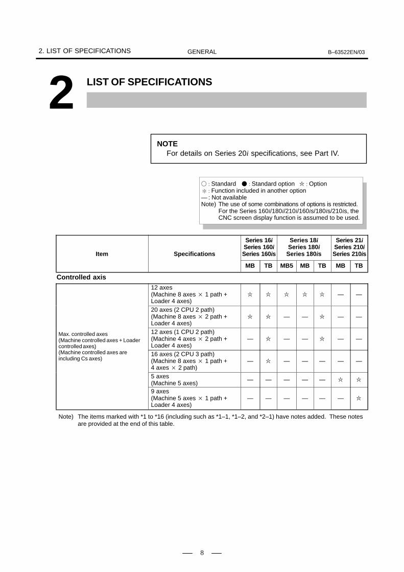
2. LIST OF SPECIFICATIONS B–63522EN/03GENERAL
8
2 LIST OF SPECIFICATIONS
NOTEFor details on Series 20i specifications, see Part IV.
� : Standard � : Standard option � : Option� : Function included in another option— : Not availableNote) The use of some combinations of options is restricted.
For the Series 160i/180i/210i/160is/180is/210is, the CNC screen display function is assumed to be used.
Item Specifications
Series 16iSeries 160iSeries 160is
Series 18iSeries 180i
Series 180is
Series 21iSeries 210iSeries 210is
MB TB MB5 MB TB MB TB
Controlled axis
Max. controlled axes
12 axes (Machine 8 axes � 1 path +Loader 4 axes)
� � � � � — —
Max. controlled axes
20 axes (2 CPU 2 path) (Machine 8 axes � 2 path +Loader 4 axes)
� � — — � — —
Max. controlled axes (Machine controlled axes + Loadercontrolled axes)(Machine controlled axes are
12 axes (1 CPU 2 path) (Machine 4 axes � 2 path +Loader 4 axes)
— � — — � — —controlled axes)(Machine controlled axes are including Cs axes)
16 axes (2 CPU 3 path) (Machine 8 axes � 1 path + 4 axes � 2 path)
— � — — — — —
5 axes(Machine 5 axes)
— — — — — � �
9 axes(Machine 5 axes � 1 path +Loader 4 axes)
— — — — — — �
Note) The items marked with *1 to *16 (including such as *1–1, *1–2, and *2–1) have notes added. These notesare provided at the end of this table.

B–63522EN/03 2. LIST OF SPECIFICATIONSGENERAL
9
Item
Series 21iSeries 210iSeries 210is
Series 18iSeries 180i
Series 180is
Series 16iSeries 160iSeries 160isSpecifications
TBMBTBMBMB5TBMB
Controlled path
1–path � � � � � � �
Controlled path2–path (2 CPU 2 path) � � — — � — —
Controlled path2–path (1 CPU 2 path) — � — — � — —3–path (2 CPU 3 path) — � — — — — —
Controlled axis (each path)
2 axes — � — — � — �Controlled axis (each path) 3 axes � — � � — � —Simultaneously controlledaxes (each path)
Simultaneous 2 axes � � � � � � �
Controlled axes
Max. 8 axes (1 path) � � � � � — —
Controlled axes Max. 8 axes (2 CPU 2 path) � � — — � — —Controlled axes expansion (total) (including Cs axes)
Max. 5 axes (1 path) — — — — — � �expansion (total) (including Cs axes) Max. 4 axes (1 CPU 2 path) — � — — � — —
Max. 8 axes (2 CPU 3 path) — � — — — — —
Simultaneously controlledMax. 6 axes � � — — — — —
Simultaneously controlledaxes expansion (total) Max. 5 axes — — � — — — —axes expansion (total)
Max. 4 axes — — — � � � �
Axis control by PMC Max. simultaneous 4 axes perpath (Not available on Cs axis)
� � � � � � �
PMC axis control expansion
Axis control by PMC is required. � � � � � � —
Function of CNC axiswaiting during PMC axiscontrol
PMC axis control expansion isrequired.
� � � � � � �
Cs contouring control
Max. 4 axes (1 path) � � — — — — —
Cs contouring control
Max. 3 axes (1 path) — — � � � — —
Cs contouring control
Max. 2 axes (1 path) — — — — — � �
Cs contouring control
4 axes for each path (2 CPU 2 path)
� � — — — — —
Cs contouring control 3 axes for each path (2 CPU 2 path)
— — — — � — —
2 axes for each path (1 CPU 2 path) *3
— � — — � — —
2 axes for each path (2 CPU 3 path)
— � — — — — —
Controlled path 1 path � � � � � — �
Controlled axes Max. 4 axes � � � � � — �
Simultaneously controlledaxes
Max. 4 axes � � � � � — �
Axis control by PMC Max. 4 axes � � � � � — �
Compound machining function Only for 1 path — � — — � — —
Axis name
Basic three axes are X, Y andZ, additional axes are optionalfrom U, V, W, A, B and C.
� — � � — � —
Axis name In case of G code system A, basic 2 axes are X and Z, additional axes are optionalfrom Y, A, B and C.
— � — — � — �
Axis name
In case of G code system B/C,basic 2 axes are X and Z, additional axes are optionalfrom Y, U, V, W, A, B and C.
— � — — � — �
Note) The items marked with *1 to *16 (including such as *1–1, *1–2, and *2–1) have notes added. These notesare provided at the end of this table.
Mac
hine
con
trol
led
axes

2. LIST OF SPECIFICATIONS B–63522EN/03GENERAL
10
Item
Series 21iSeries 210iSeries 210is
Series 18iSeries 180i
Series 180is
Series 16iSeries 160iSeries 160isSpecifications
TBMBTBMBMB5TBMB
Servo motor connection numberexpansion at torque tandemcontrol
� — � � — — —
Axis recomposition Only for 2 path — � — — � — —Synchronous operation control Only for 1 path — � — — � — —
Simple synchronous control1 pair — � — — � � �
Simple synchronous control4 pairs � — � � — — —
Twin table control � — � � — � —Bar feeder control — � — — � — �
Angular axis control � � � � � � �
Arbitrary angular axis control � � � � � — �
B–axis control — � — — � — �
Tandem control � � � � � � �
Tandem Disturbance Elimination control
Simple synchronous control isrequired.
� � � � � — —
Oscillation command by PMCaxis
PMC axis control is required. � � � � � � �
Torque control Included in PMC axis control � � � � � — —Control axis detach � � � � � � �
Chopping � — � � — — —
Least input increment 0.001mm, 0.001deg,0.0001inch
� � � � � � �
Increment system 1/10 0.0001mm, 0.0001deg,0.00001inch
� � � � � � �
Increment system 1/100 0.00001mm, 0.00001deg,0.000001inch
— � — — � — —
Flexible feed gear Optional DMR � � � � � � �
Learning control � � � � � — —Preview repetitive control � � � � � — —Dual position feedback � � � � � � �
Learning memory expansion � � � � � — —Fine Acc & Dec control � � � � � � �
HRV control � � � � � � �
High speed HRV control � � � � � � —Inch/metric conversion � � � � � � �
InterlockAll axes/each axis/each direc-tion/block start/cutting blockstart
� � � � � � �
Machine lock All axes/each axis � � � � � � �
Emergency stop � � � � � � �
Overtravel � � � � � � �
Stored stroke check 1 � � � � � � �
Stroke limit external setting � — � � — � —Stored stroke check 2 � — � � — � —Stored stroke check 3 � — � � — — —Stored stroke check 2, 3 — � — — � — �
Stroke limit check before move � � � � � � —Chuck and tail stock barrier — � — — � — �
Note) The items marked with *1 to *16 (including such as *1–1, *1–2, and *2–1) have notes added. These notesare provided at the end of this table.

B–63522EN/03 2. LIST OF SPECIFICATIONSGENERAL
11
Item
Series 21iSeries 210iSeries 210is
Series 18iSeries 180i
Series 180is
Series 16iSeries 160iSeries 160isSpecifications
TBMBTBMBMB5TBMB
Mirror image Each axis � � � � � � �
Follow–up � � � � � � �
Servo off/mechanical handlefeed
� � � � � � �
Chamfering on/off — � — — � — �
Interference check between2–path
� Only for 2 path� Tool offset number is
available to max.64 in this function
� � — — � — —
Interference check for rotaryarea
� � � � � — —
Unexpected disturbance torquedetection function
� � � � � � �
Fine torque sensing � � � � � — —Rotary axis control � � � � � — —Position switch � � � � � � �
High–speed position switch � � � � � — —Direction–dependent type high–speed position switch
� � � � � — —
Linear scale I/F with absoluteaddress reference mark
� � � � � � �
Linear scale with absolute ad-dress reference mark expan-sion
� � � � � � �
Temporary absolute coordinatesetting
� � � � � — �
Dual check safety � � � � � � �
Inclined rotary axis control RISC board is required. *15 � — � — — — —
Operation
Automatic operation (memory) � � � � � � �
MDI operation � � � � � � �
DNC operation Reader/puncher interface is required.
� � � � � � �
DNC operation with MemoryCard
PCMCIA Card Attachment is required. *1–3
� � � � � � �
Schedule function Only for 1 path � � � � � � �
Program number search � � � � � � �
Sequence number search � � � � � � �
Sequence number comparisonand stop
� � � � � � �
Program restart � � � � � � �
Tool retract and recover � � � � � — —Manual intervention and return � � � � � � �
Retraction for rigid tapping � — � � — � —Buffer register � � � � � � �
Dry run � � � � � � �
Single block � � � � � � �
Jog feed � � � � � � �
Note) The items marked with *1 to *16 (including such as *1–1, *1–2, and *2–1) have notes added. These notesare provided at the end of this table.

2. LIST OF SPECIFICATIONS B–63522EN/03GENERAL
12
Item
Series 21iSeries 210iSeries 210is
Series 18iSeries 180i
Series 180is
Series 16iSeries 160iSeries 160isSpecifications
TBMBTBMBMB5TBMB
Manual reference position return � � � � � � �
Reference position setting without DOG
� � � � � � �
Reference position setting with mechanical stopper
� � � � � � �
Reference position shift � � � � � — —
Manual handle feed1 unit/each path � � � � � � �
Manual handle feed 2 units — � — — � — �Manual handle feed2 units/3 units � — � � — � —
Manual handle feed rate �1, �10, �m, �nm: 0 to 127, n: 0 to 1000
� � � � � � �
Tool direction handle feed � — � � — — —Tool direction handle feed B Tool direction + normal direction � — � � — — —Manual feed for 5–axis machining
� � � — — — —
Manual handle interruption � � � � � � �
Incremental feed �1, �10, �100, �1000 � � � � � � �
Jog and handle simultaneous mode
� � � � � � �
Manual numerical command � � � � � — —Manual liner/circular interpolation Only for 1 path � � � � � � —Retrace � — � � — � —Manual handle retrace Manual handle feed is required. — � — — � — �
Reference position signal output — � — — � — �
Interpolation functions
Positioning G00 (Linear interpolation typepositioning is possible)
� � � � � � �
Single direction positioning G60 � � � � � � —Exact stop mode G61 � — � � — � —Tapping mode G63 � — � � — � —Cutting mode G64 � — � � — � —Exact stop G09 � — � � — � —Linear interpolation � � � � � � �
Circular interpolation Multi–quadrant is possible � � � � � � �
Exponential interpolation � — � � — — —
Dwell
Dwell in seconds and dwell inrevolution (In case of dwell inrevolution for M system, thread-ing, synchronous cutting optionis required.)
� � � � � � �
Polar coordinate interpolation � � � � � — �
Cylindrical interpolation � � � � � � �
Helical interpolation Circular interpolation plus max. 2 axes linear interpolation
� � � � � � —
Helical interpolation BCircular interpolation plus max. 4 axes linear interpolation
*13 *14� � — — — — —
Involute interpolation � — � � — — —
Note) The items marked with *1 to *16 (including such as *1–1, *1–2, and *2–1) have notes added. These notesare provided at the end of this table.

B–63522EN/03 2. LIST OF SPECIFICATIONSGENERAL
13
Item
Series 21iSeries 210iSeries 210is
Series 18iSeries 180i
Series 180is
Series 16iSeries 160iSeries 160isSpecifications
TBMBTBMBMB5TBMB
Hypothetical axis interpolation � � � � � — —Conical/spiral interpolation *13 *14 � � � � � — —Smooth interpolation *15 *16 � � � � � — —Nano Smoothing � — � � — — —Threading, synchronous cutting � � � � � � �
Multiple threading — � — — � — �
Threading retract — � — — � — �
Continuous threading — � — — � — �
Variable lead threading — � — — � — �
Circular threading — � — — � — —Polygon turning — � — — � — �
Polygon machining with twospindles
— � — — � — �
Skip G31 � � � � � � �
Multi–step skip � � � � � � �
High–speed skip Input signal is 8 points, but 21i/210i/210is are only 1 point.
� � � � � � �
Continuous high–speed skip � — � � — — —Torque limit skip � � � � � — �
Reference position return G28 � � � � � � �
Reference position return check G27 � � � � � � �
2nd reference position return � � � � � � �
3rd/4th reference position return � � � � � � �
Floating reference position return
� � � � � — —
Normal direction control � — � � — � —Gentle normal direction control � — � � — — —NURBS interpolation *15 *16 � � � � � — —
Three–dimensional circular interpolation
RISC board is required. *14 *15
� � � — — — —
Continuous dressing For grinding machine � — � � — � —Infeed control For grinding machine � — � � — � —Balance cutting Only for 2 path — � — — � — —Index table indexing � — � � — � —High–speed cycle cutting Only for 1 path � � � � � — —Retract of high–speed cyclecutting
� � � � � — —
High–speed linear interpolation � — � � — — —General purpose retract � � � � � � �
Note) The items marked with *1 to *16 (including such as *1–1, *1–2, and *2–1) have notes added. These notesare provided at the end of this table.

2. LIST OF SPECIFICATIONS B–63522EN/03GENERAL
14
Item
Series 21iSeries 210iSeries 210is
Series 18iSeries 180i
Series 180is
Series 16iSeries 160iSeries 160isSpecifications
TBMBTBMBMB5TBMB
Feed function
Rapid traverse rateMax. 240m/min (1µm) � � � � � � �
Rapid traverse rate Max. 100m/min (0.1µm) � � � � � � �Rapid traverse rateMax. 10m/min (0.01µm) — � — — � — —
Rapid traverse override Fo, 25, 50, 100% or 0 to 100%(1% Step)
� � � � � � �
Feed per minute � � � � � � �
Feed per revolutionFor M system, threading, synchronous cutting option is required.
� � � � � � �
Without position coder feed perrevolution
Included in Without position coder constant surface speed control.
— � — — � — �
Without position coder constantsurface speed control
— � — — � — �
Tangential speed constant control � � � � � � �
Cutting feedrate clamp � � � � � � �
Automatic acceleration/decel-eration
Rapid traverse: linearCutting feed: exponential
� � � � � � �
Rapid traverse bell–shaped acceleration/deceleration
� � � � � � �
Positioning by optimal acceleration
� � � � � � —
Optimum torque acceleration/deceleration
AI high–precision contour con-trol or AI nano high–precisioncontour control is required. *15
� � � � � — —
Linear acceleration/decelerationafter cutting feed interpolation
� � � � � � �
Bell–shaped acceleration/deceleration after cutting feed interpolation
� � � � � � �
Linear acceleration/decelerationbefore cutting feed interpolation
For M system, feed per minute only
� � � � � — —
Feedrate override 0 to 254% � � � � � � �
2nd feedrate override 0 to 254% � � � � � — —One–digit F code feed � — � � — � —Inverse time feed � — � � — � —Jog override 0 to 655.34% � � � � � � �
Override cancel � � � � � � �
Manual per revolution feed — � — — � — �
The stop position setting withthe manual feed
— � — — � — �
External deceleration � � � � � � �
Feed stop � � � � � — —Advanced preview control � � � � � � —AI advanced preview control — — — — — � —AI contour control � — � � — � —AI nano contour control � � � � � � —
Note) The items marked with *1 to *16 (including such as *1–1, *1–2, and *2–1) have notes added. These notesare provided at the end of this table.

B–63522EN/03 2. LIST OF SPECIFICATIONSGENERAL
15
Item
Series 21iSeries 210iSeries 210is
Series 18iSeries 180i
Series 180is
Series 16iSeries 160iSeries 160isSpecifications
TBMBTBMBMB5TBMB
Bell–shaped acceleration/deceleration before look ahead interpolation
AI contour control or AI nano contour control is required.
� — � � — � —
High–precision contour control RISC board is required. *15 � � � � � — —
AI high–precision contour controlLook–ahead block no. is Max. 600.RISC board is required. *15
� � � � � — —
AI nano high–precision contourcontrol
Look–ahead block no. is Max. 600.RISC board is required. *15
� � � � � — —
Jerk control
Any of following functions is required.� Bell–type acceleration/
deceleration before look ahead interpolation
� AI high–precision contour control (*15)
� AI nano high–precision contour control (*15) *13
� � � � � � —
Rigid tapping bell–shaped acceleration/deceleration
Rigid tapping is required. � — � � — � —
Program input
Tape code EIA RS244/ISO840 � � � � � � �
Label skip � � � � � � �
Parity check Horizontal and vertical parity � � � � � � �
Control in/out � � � � � � �
Optional block skip1 � � � � � � �
Optional block skip9 � � � � � � �
Max. programmable dimension ±8–digit � � � � � � �
Program numberO4–digit � � � � � � �
Program numberO8–digit � � � � � — —
Sequence number N5–digit � � � � � � �
Absolute/incremental programming
Combined use in the same block
� � � � � � �
Decimal point programming/pocket calculator type decimalpoint programming
� � � � � � �
Input unit 10 time multiply � � � � � � �
Diameter/Radius programming (X axis)
— � — — � — �
Diameter/Radius Dynamic Switching
— � — — � — —
Plane selection G17, G18, G19 � � � � � � �
Rotary axis designation � � � � � � �
Rotary axis roll–over � � � � � � �
Polar coordinate command � — � � — � —Coordinate system setting � � � � � � �
Automatic coordinate system setting
� � � � � � �
Note) The items marked with *1 to *16 (including such as *1–1, *1–2, and *2–1) have notes added. These notesare provided at the end of this table.
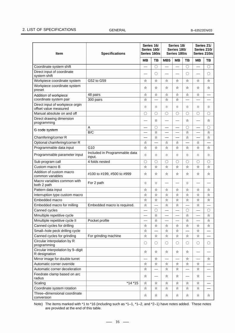
2. LIST OF SPECIFICATIONS B–63522EN/03GENERAL
16
Item
Series 21iSeries 210iSeries 210is
Series 18iSeries 180i
Series 180is
Series 16iSeries 160iSeries 160isSpecifications
TBMBTBMBMB5TBMB
Coordinate system shift — � — — � — �
Direct input of coordinate system shift
— � — — � — �
Workpiece coordinate system G52 to G59 � � � � � � �
Workpiece coordinate system preset
� � � � � � �
Addition of workpiece coordinate system pair
48 pairs � � � � � � —Addition of workpiece coordinate system pair 300 pairs � — � � — — —Direct input of workpiece orgin offset value measured
� � � � � � �
Manual absolute on and off � � � � � � �
Direct drawing dimension programming
— � — — � — �
G code systemA — � — — � — �
G code systemB/C — � — — � — �
Chamfering/corner R — � — — � — �
Optional chamfering/corner R � — � � — � —Programmable data input G10 � � � � � � �
Programmable parameter input Included in Programmable data input.
� � � � � � �
Sub program call 4 folds nested � � � � � � �
Custom macro B � � � � � � �
Addition of custom macro common variables
#100 to #199, #500 to #999 � � � � � � �
Macro variables common with both 2 path
For 2 path � � — — � — —
Pattern data input � � � � � � �
Interruption type custom macro � � � � � � �
Embedded macro � � � � � � �
Embedded macro for milling Embedded macro is required. � — � � — � —Canned cycles — � — — � — �
Mmultiple repetitive cycle — � — — � — �
Mmultiple repetitive cycle II Pocket profile — � — — � — �
Canned cycles for drilling � � � � � � �
Small–hole peck drilling cycle � — � � — � —Canned cycles for grinding For grinding machine � � � � � � —Circular interpolation by R programming
� � � � � � �
Circular interpolation by 9–digit R designation
� � � � � — —
Mirror image for double turret — � — — � — �
Automatic corner override � � � � � � —Automatic corner deceleration � — � � — � —Feedrate clamp based on arc radius
� — � � — � —
Scaling *14 *15 � � � � � � —Coordinate system rotation � � � � � � —Three–dimensional coordinate conversion
� � � � � � �
Note) The items marked with *1 to *16 (including such as *1–1, *1–2, and *2–1) have notes added. These notesare provided at the end of this table.

B–63522EN/03 2. LIST OF SPECIFICATIONSGENERAL
17
Item
Series 21iSeries 210iSeries 210is
Series 18iSeries 180i
Series 180is
Series 16iSeries 160iSeries 160isSpecifications
TBMBTBMBMB5TBMB
Tilted working plane command � — � � — — —Programmable mirror image *14 *15 � � � � � � —Figure copy � — � � — — —Tape format for FANUC Series 15
� � � � � — —
Tape format for FANUC Series 10/11
— — — — — � �
Conversational programming with graphic function
Only for 1 path � � � � � � —
Macro executor *4 � � � � � � �
Expanded P code macro variable 20000
� � � � � � �
C language executor *4 � � � � � � �
Conversational programming function for machining center
Super CAP i M *1–1 � — � � — � —NC format output *1–1 � — � � — � —Conversational C language programming
*1–1 � — � � — � —
Contour figure repetition *1–1 � — � � — � —Background graphic *1–1 � — � � — — —U–axis conversational programming
*1–1 � — � � — � —
Contour pocket machining B *1–1 � — � � — � —Contour figure block number expansion
*1–1 � — � � — � —
Operation guidance function for milling machine
MANUAL GUIDE *1–1 � — � � — � —Guidance cutting *1–1 � — � � — � —
Conversational programming function for lathe
Super CAP i TFor 1 path latheFor 2 path latheFor 3 path lathe *1–1
— � — — � — �
NC format output *1–1 — � — — � — �
C–axis conversational programming
*1–1 — � — — � — �
Y–axis conversational programming
*1–1 — � — — � — �
P code macro variable 4000 *1–1 — � — — � — �
Back machining by sub–spindle *1–1 — � — — � — �
Chuck data extension 60 *1–1 — � — — � — �
T code offset pair extension *1–1 — � — — � — �
Animated simulation interference check
*1–1 — � — — � — �
Complex Lathe Application Only for 2 path *1–1 — � — — � — —
Note) The items marked with *1 to *16 (including such as *1–1, *1–2, and *2–1) have notes added. These notesare provided at the end of this table.

2. LIST OF SPECIFICATIONS B–63522EN/03GENERAL
18
Item
Series 21iSeries 210iSeries 210is
Series 18iSeries 180i
Series 180is
Series 16iSeries 160iSeries 160isSpecifications
TBMBTBMBMB5TBMB
Complex Lathe Application for 3 path control
Only for 3 path *1–1 — � — — — — —
Contour Grooving *1–1 — � — — � — �
Contour Grooving Function withButton Tool
*1–1 — � — — � — �
Spindle positioning type Y–axis milling
*1–1 — � — — � — �
Symbol CAP i TFor 1 path latheFor 2 path lathe *1–1
— � — — � — �
Sub cycle function *1–1 — � — — � — �
Extended sub cycle function *1–1 — � — — � — �
Automatic process determination *1–1 — � — — � — �
Automatic process determination function B
*1–1 — � — — � — �
Animated simulation function *1–1 — � — — � — �
Animated simulation function forvertical lathe
*1–1 — � — — � — �
C–axis process function *1–1 — � — — � — �
C–axis process function B *1–1 — � — — � — �
Y–axis process function *1–1 — � — — � — �
Back machining function *1–1 — � — — � — �
Balance cut process function Only for 2 path *1–1 — � — — � — —Conversational screen display language change over
*1–1 — � — — � — �
Sub memory addition *1–1 — � — — � — �
Registration of file name to floppy cassette
*1–1 — � — — � — �
Next tool preparation *1–1 — � — — � — �
Operation guidance function for general purpose lathe
Manual guide For 1 path lathe *1–1 — � — — � — �
Minus X Area cutting function *1–1 — � — — � — �
C–axis machining A function *1–1 — � — — � — �
Back side Tool post function *1–1 — � — — � — �
Integrated Operation guidance function
MANUAL GUIDE i Basic *1–1 � � � � � � �
MANUAL GUIDE i Milling Cycle *1–1 � � � � � � �
MANUAL GUIDE i Turning Cycle *1–1 — � — — � — �
MANUAL GUIDE i Animation *1–1 � � � � � � �
MANUAL GUIDE i Set–up Guidance
*1–1 � � � � � � �
MANUAL GUIDE i Multi path lathe function
*1–1 — � — — � — —
MANUAL GUIDE i Spindle movement animation for automatic lathe
*1–1 — � — — � — —
Note) The items marked with *1 to *16 (including such as *1–1, *1–2, and *2–1) have notes added. These notesare provided at the end of this table.

B–63522EN/03 2. LIST OF SPECIFICATIONSGENERAL
19
Item
Series 21iSeries 210iSeries 210is
Series 18iSeries 180i
Series 180is
Series 16iSeries 160iSeries 160isSpecifications
TBMBTBMBMB5TBMB
Auxiliary/Spindle speed function
Auxiliary function M8–digit � � � � � � �
2nd auxiliary function B8–digit � � � � � � �
Auxiliary function lock � � � � � � �
High–speed M/S/T/B interface � � � � � � �
Waiting function Only for 2 path � � — — � — —Multiple command of auxiliary function
3 � � � � � � �
M code group check � � � � � — —Spindle speed function S5–digit, binary output � � � � � � �
Spindle serial output S5–digit, serial output (1st/2nd) � � � � � � �
3rd spindle serial output — — � � � — —3rd /4th spindle serial output � � — — — — —Spindle analog output S5–digit, analog output � � � � � � �
Constant surface speed control � � � � � � �
Spindle override 0 to 254% � � � � � � �
Actual spindle speed output — � — — � — �
Spindle speed fluctuation detection
� � � � � — �
1st spindle orientation � � � � � � �
1st spindle output switching function
� � � � � � �
2nd spindle orientation � � � � � � �
2nd spindle output switching function
� � � � � � �
3rd spindle orientation — — � � � — —3rd spindle output switching function
— — � � � — —
3rd/4th spindle orientation � � — — — — —3rd/4th spindle output switchingfunction
� � — — — — —
Spindle synchronous control � � � � � � �
Spindle simple synchronous control
� � � � � � �
Multi spindle control � � � � � — �
Spindle positioning — � — — � — �
Rigid tapping � � � � � � �
Three–dimensional rigid tapping � � � � � � —Rigid tapping by manual handle � — � � — — —
Tool function/Tool compensation
Tool functionT7+1/T6+2 digits — � — — � — �
Tool functionT8 digits � — � � — � —
Note) The items marked with *1 to *16 (including such as *1–1, *1–2, and *2–1) have notes added. These notesare provided at the end of this table.
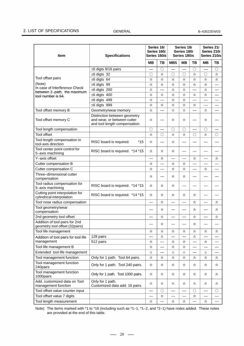
2. LIST OF SPECIFICATIONS B–63522EN/03GENERAL
20
Item
Series 21iSeries 210iSeries 210is
Series 18iSeries 180i
Series 180is
Series 16iSeries 160iSeries 160isSpecifications
TBMBTBMBMB5TBMB
Tool offset pairs
±6 digts 9/16 pairs — � — — � — �
Tool offset pairs±6 digts 32 � � � � � � �
Tool offset pairs
(Note)±6 digts 64 � � � � � � �
(Note)In case of Interference Check
±6 digts 99 � � � � � � —In case of Interference Check between 2–path, the maximum
±6 digts 200 � — � � — � —between 2–path, the maximum tool number is 64. ±6 digts 400 � � � � � � —tool number is 64.
±6 digts 499 � — � � — — —±6 digts 999 � � � � � — —
Tool offset memory B Geometry/wear memory � — � � — � —
Tool offset memory CDistinction between geometry and wear, or between cutter and tool length compensation.
� — � � — � —
Tool length compensation � — � � — � —Tool offset � � � � � � �
Tool length compensation in tool axis direction
RISC board is required. *15 � — � — — — —
Tool center point control for 5–axis machining
RISC board is required. *14 *15 � � � — — — —
Y–axis offset — � — — � — �
Cutter compensation B � — � � — — —Cutter compensation C � — � � — � —Three–dimensional cutter compensation
� — � � — — —
Tool radius compensation for 5–axis machining
RISC board is required. *14 *15 � � � — — — —
Cutting point interpolation for cylindrical interpolation
RISC board is required. *14 *15 � � � � � — —
Tool nose radius compensation — � — — � — �
Tool geometry/wear compensation
— � — — � — �
2nd geometry tool offset — � — — � — �
Addition of tool pairs for 2nd geometry tool offset (32pairs)
— � — — � — —
Tool life management � � � � � � �
Addition of tool pairs for tool life management
128 pairs — � — — � — —Addition of tool pairs for tool life management 512 pairs � — � � — � —Tool life management B � — � � — — —Extended tool life management � — � � — � —Tool management function Only for 1 path. Tool 64 pairs. � � � � � � �
Tool management function 240pairs
Only for 1 path. Tool 240 pairs. � � � � � � �
Tool management function 1000pairs
Only for 1 path. Tool 1000 pairs. � � � � � � �
Add. customized data on Tool management function
Only for 1 path. Customized data add. 16 pairs.
� � � � � � �
Tool offset value counter input — � — — � — �
Tool offset value 7 digits — � — — � — —Tool length measurement � — � � — � —
Note) The items marked with *1 to *16 (including such as *1–1, *1–2, and *2–1) have notes added. These notesare provided at the end of this table.

B–63522EN/03 2. LIST OF SPECIFICATIONSGENERAL
21
Item
Series 21iSeries 210iSeries 210is
Series 18iSeries 180i
Series 180is
Series 16iSeries 160iSeries 160isSpecifications
TBMBTBMBMB5TBMB
Automatic tool length measurement
� — � � — � —
Tool length/work zero point measurement B
� — � � — — —
Automatic tool offset — � — — � — �
Direct input of tool offset value measured
— � — — � — �
Direct input of tool offset value measured B
— � — — � — �
Direct input of offset value measured B for 2 spindle lathe
— � — — � — �
Guidance for machining preparation
Manual guide is required. � � � � � � �
Measurement cycle Embedded macro or Manual guide is required.
� — � � — � —
Wheel wear compensation � — � � — — —Automatic alteration of tool position compensation
— � — — � — —
Rotary table dynamic fixture offset
� — � � — — —
Changing active offset value with manual move
� � � � � � �
Accuracy compensasion function
Backlash compensation � � � � � � �
Backlash compensation for eachrapid traverse and cutting feed
� � � � � � �
Smooth backlash compensation � � � � � — —Stored pitch error compensation � � � � � � �
Interpolation type pitch error compensation
Stored pitch error compensationis required.
� � � � � — —
Bi–directional pitch error compensation
Stored pitch error compensationis required.
� � � � � — �
Extended bi–directional pitch error compensation
Stored pitch error compensation,Bi–directional pitch error compensation are required.
� � � � � — �
Periodical secondary pitch errorcompensation
Stored pitch error compensationis required.
� � � � � — —
Inclination compensation � � � � � � —Straightness compensation � � � � � — —Straightness compensation 128 points
Included in interpolation type straightness compensation.
� � � � � — —
Interpolation type straightness compensation
Stored pitch error compensationis required.
� � � � � — —
Thermal growth compensation along tool vector
� — � — — — —
Hobbing/Electric gear boxFunction for hobbing machine � — � � — — —Hobbing function — � — — � — —
Note) The items marked with *1 to *16 (including such as *1–1, *1–2, and *2–1) have notes added. These notesare provided at the end of this table.

2. LIST OF SPECIFICATIONS B–63522EN/03GENERAL
22
Item
Series 21iSeries 210iSeries 210is
Series 18iSeries 180i
Series 180is
Series 16iSeries 160iSeries 160isSpecifications
TBMBTBMBMB5TBMB
Simple electric gear box � — � � — � —
Skip function for EGB axis Simple electric gear box is required.
� — � � — — —
Electric gear box 2 pair Simple electric gear box is required.
� — � � — — —
Electric gear box automatic phase synchronization
Simple electric gear box is required.
� — � � — — —
Spindle electric gear box Simple electric gear box, Cscontouring control are required.
� — � � — — —
Flexible synchronous control � — � � — — —
Editing operation
Part program storage length *5
10m (4Kbyte) — — — — — � �
Part program storage length *5
20m (8Kbyte) — — � � � � �
Part program storage length *5
40m (16Kbyte) � � � � � � �
Part program storage length *5
80m (32Kbyte) � � � � � � �
Part program storage length *5
160m (64Kbyte) � � � � � � �
Part program storage length *5 320m (128Kbyte) � � � � � � �Part program storage length *5640m (256Kbyte) � � � � � � �
1280m (512Kbyte) � � � � � � �
2560m (only for 1 path)(1024Kbyte)
� � � � � — —
5120m (only for 1 path)(2048Kbyte)
� � — — — — —
Number of registerable
63 � � � � � � �
Number of registerable 125 � � � � � � �
Number of registerable programs 200 � � � � � � �programs
400 � � � � � � —1000 � � � � � — —
Part program editing � � � � � � �
Program protect � � � � � � �
Program Encryption � � � � � — —Background editing � � � � � � �
Extended part program editing � � � � � � �
Program copy between 2–path Only for 2 path � � — — � — —Playback � � � � � � �
Machining time stamp � � � � � — —
Setting and displayStatus display � � � � � � �
Clock function � � � � � � �
Current position display � � � � � � �
Program display Program name 31 characters � � � � � � �
Parameter setting and dispaly � � � � � � �
Self–diagnosis function � � � � � � �
Alarm display � � � � � � �
Alarm history display � � � � � � �
Note) The items marked with *1 to *16 (including such as *1–1, *1–2, and *2–1) have notes added. These notesare provided at the end of this table.

B–63522EN/03 2. LIST OF SPECIFICATIONSGENERAL
23
Item
Series 21iSeries 210iSeries 210is
Series 18iSeries 180i
Series 180is
Series 16iSeries 160iSeries 160isSpecifications
TBMBTBMBMB5TBMB
Operator message history display � � � � � � �
Operation history display � � � � � � �
Help function � � � � � � �
FACTOLINK *1 � � � � � � �
Remote diagnostic
� Host software+Modem or � Machine remote diagnosis
package+Ethernet (Function:Reading CNC/PMC status, etc.) *1
� � � � � � �
Run hour and parts count display � � � � � � �
Actual cutting feedrate display � � � � � � �
Display of spindle speed and T code at all screens
� � � � � � �
Directory display of floppy cassette
� � � � � � �
Directory display and punch for each group
� � � � � � �
Graphic function � � � � � � �
Dynamic graphic display � � � � � � �
Background graphic (without CAP)
� — � � — — —
Optional path name display Only for 2 path � � — — � — —Operating monitor screen Load meter etc. � � � � � � �
Servo setting screen � � � � � � �
Spindle setting screen Only for αi/α series � � � � � � �
Servo waveform display Graphic display circuit is required. � � � � � � �
SERVO GUIDE Mate � � � � � � �
Display of hardware and software configuration
� � � � � � �
Servo information screen � � � � � � �
Spindle information screen Only for αi/α series � � � � � � �
Periodic maintenance screen � � � � � � �
Maintenance information screen � � � � � � �
Trouble diagnosis � � � � � � �
Machine alarm diagnosis � � � � � � �
Software operator’s panel � � � � � � �
Software operator’s panel general purpose switch
Software operator’s panel is required.
� � � � � � �
Software operator’s panel gen-eral purpose switch expansion
Software operator’s panel gen-eral purpose switch is required.
� � � � � — —
External touch panel interface It is impossible to use with the Touch panel
� � � � � � �
Virtual MDI Key for display link Touch panel is required. *1–3 � � � � � � �
FANUC PICTURE function � � � � � � �
Note) The items marked with *1 to *16 (including such as *1–1, *1–2, and *2–1) have notes added. These notesare provided at the end of this table.

2. LIST OF SPECIFICATIONS B–63522EN/03GENERAL
24
Item
Series 21iSeries 210iSeries 210is
Series 18iSeries 180i
Series 180is
Series 16iSeries 160iSeries 160isSpecifications
TBMBTBMBMB5TBMB
Multi–language display
English � � � � � � �
Multi–language display
Japanese (Chinese character) � � � � � � �
Multi–language display
German/French � � � � � � �
Multi–language display
Italian � � � � � � �
Multi–language display
Chinese � � � � � � �
Multi–language displaySpanish � � � � � � �
Multi–language display Korean � � � � � � �Multi–language displayPortuguese � � � � � � �
Polish � � � � � � �
Hungarian � � � � � � �
Swedish � � � � � � �
Czech � � � � � � �
Dutch � — � � — � —Data protection key 4 types � � � � � � �
Erase CRT screen display Manual or Automatic *1 � � � � � � �
Parameter set supporting screen � � � � � � �
Machining condition selecting screen
Advanced preview control or AI contour control and so on is required.
� � � � � � �
Data input/output
Reader/puncher interfaceReader/puncher (Ch.1) interface � � � � � � �
Reader/puncher interfaceReader/puncher (Ch.2) interface � � � � � � �
Input/output simultaneous operation
Only for 1 path � — � � — — —
Remote buffer Only for 1 path � � � � � � �
High–speed remote buffer A Only for 1 path � � � � � � �
High–speed remote buffer B Only for 1 path � — � � — � —Data server Only for 1 path *1 � � � � � � �
External I/O device control � � � � � � �
DNC1 control
Uploading/downloading a part program, Reading/writing CNC data, Transfer of PMC data, Memory operation control, etc.
� � � � � � �
DNC2 control
Only for 1 pathUploading/downloading a part program, Reading/writing CNC data, Transfer of PMC data, Memory operation control, etc.
� � � � � � �
Modem card control *1 � � � � � � �
External tool offset � � � � � � �
External message � � � � � � �
External machine zero point shift � � � � � � �
External data input Including above 3 items � � � � � � �
External key input � � � � � � �
External program input � � � � � � �
External workpiece number search
9999 � � � � � � �
External program number search 1 to 9999 � � � � � � �
Note) The items marked with *1 to *16 (including such as *1–1, *1–2, and *2–1) have notes added. These notesare provided at the end of this table.

B–63522EN/03 2. LIST OF SPECIFICATIONSGENERAL
25
Item
Series 21iSeries 210iSeries 210is
Series 18iSeries 180i
Series 180is
Series 16iSeries 160iSeries 160isSpecifications
TBMBTBMBMB5TBMB
One touch macro call � � � � � � �
Memory card input/output � � � � � � �
Screen hard copy *1–2 � � � � � � �
Power Mate CNC manager � � � � � � �
Interface functionEmbedded Ethernet � � � � � � �
Ethernet Ethernet board is required. � � � � � � �
Fast Ethernet Fast Ethernet board is required. � � � � � � �
I/O Link–II Master/Slave � � � � � � �
PROFIBUS–DP Master/Slave � � � � � � �
DeviceNet Master/Slave � � � � � � �
FL–net Only for stand–alone type � � � � � � �
Others
Status output signal
NC ready, servo ready, automatic operation, automatic operation start lamp, feed hold, reset, NC alarm, distribution end, rewinding, inch input, cutting, inposition, thread cutting, tapping, etc.
� � � � � � �
Control unit incorporated type7.2″ monochrome LCD *1–1 � � � � � � �
Control unit incorporated typedisplay unit *10 *11
9.5″ monochrome LCD *1–1 � � � � � � �
display unit *10 *11(Not available in 160i/180i/210i) 8.4″ color LCD *1–1 � � � � � � �(Not available in 160i/180i/210i)
10.4″ color LCD � � � � � � �
Control unit dimensions for
Without option slots (depth 60mm)
� � � � � � �
Control unit dimensions for LCD unit mounted type (depth)
Option 2 slots (depth 110mm) � � � � � � �LCD unit mounted type (depth) Option 3 slots (depth 125mm) � � � � � — —
Option 4 slots (depth 170mm) � � � � � — —
Display unit for stand–alone
7.2″ monochrome LCD(Display Link type) *1
� � � � � � �
Display unit for stand–alonetype control unit *10 *12 9.5″ monochrome LCD *1 � � � � � � �type control unit *10 *12
10.4″ color LCD � � � � � � �
Control unit dimensions for stand–alone type control unit
1 slot (Width 60mm) � � � � � � �
stand–alone type control unit (width) 3 slots (Width 172mm) � � � � � � �
MDI unit
Separate MDI (small size) *1 � � � � � � �
MDI unit
Separate MDI(standard size, horizontal/vertical type)
� � � � � � �
MDI unitSeparate MDI (61key, horizontal/vertical type)
� � � � � � �
Separate MDI (personal com-puter key, vertical type) *2–1
� � � � � � �
Touch panel Only for 10.4″ LCD *11*12 � � � � � � �
Note) The items marked with *1 to *16 (including such as *1–1, *1–2, and *2–1) have notes added. These notesare provided at the end of this table.

2. LIST OF SPECIFICATIONS B–63522EN/03GENERAL
26
Item
Series 21iSeries 210iSeries 210is
Series 18iSeries 180i
Series 180is
Series 16iSeries 160iSeries 160isSpecifications
TBMBTBMBMB5TBMB
PMC–SA1 Basic instruction: 5µsec/stepMax. step number ladder: 5000
— — — — — � �
PMC–SB7Basic instruction: 0.033µsec/stepMax. step number ladder: 64000
� � � � � � �
PMC–SB7Step sequence function � � � � � � �
C languageMax. 2MB (PMC–SB7 is required)
� � � � � � �
C languageNonvolatile memory expansion � � � � � � �
I/O Link expansion DI/DO points: 2048/2048 points (PMC–SB7 is required)
� � � � � � �
Standard operator’s panel � � � � � � �
Machine interface (I/O Link)
I/O Unit–MODEL A � � � � � � �
Machine interface (I/O Link) I/O Unit–MODEL B � � � � � � �Machine interface (I/O Link)Max. DI/DO points: 1024/1024 points or 2048/2048 points
Operator’s panel I/O module � � � � � � �Max. DI/DO points: 1024/1024 points or 2048/2048 points(Note) If using 2048/2048 points, I/O Link expansion option is
Power magnetics control I/O module
� � � � � � �
I/O Link expansion option is necessary.
Connection panel I/O module (DI/DO module, 2A output module, Analog input module)
� � � � � � �
I/O Link – AS–i converter � � � � � � �
Manula pulse generator � � � � � � �
Pendant type manual pulse generator
With axis selection and magnification switches
� � � � � � �
Codeless manual pulse generator
Restricted use in Japan � � � � � � �
Handy machine operator’s panel � � � � � � �
Connectable servo motorFANUC AC servo motor
αiS series, αi series, α series, βseries
� � � � � � �
Connectable servo amplifierFANUC servo amplifier
αi series, α series, βseries� � � � � � �
Position detector unit for full–closed control
Pulse coder/optical scale (2–phase pulse interface)
� � � � � � �
full–closed control (for full–closed control) Pulse coder/optical scale
(serial interface)� � � � � � �
Connectable spindle motorFANUC AC spindle motor
αi series, α series, etc.� � � � � � �
Connectable spindle amplifierFANUC servo amplifier
αi series, α series� � � � � � �
Connectable spindle amplifierAnalog interface � � � � � � �
Input power supply DC24V±10% � � � � � � �
Ambient temperature of unit *12
LCD mounted type control unit, display unit for stand–alone type control unitAt operating: 0�C to 58�CAt nonoperating: –20�C to 60�C
� � � � � � �
Stand alone type control unitAt operating: 0�C to 55�CAt nonoperating: –20�C to 60�C
� � � � � � �
Note) The items marked with *1 to *16 (including such as *1–1, *1–2, and *2–1) have notes added. These notesare provided at the end of this table.
PM
C S
YS
TE
M

B–63522EN/03 2. LIST OF SPECIFICATIONSGENERAL
27
Item
Series 21iSeries 210iSeries 210is
Series 18iSeries 180i
Series 180is
Series 16iSeries 160iSeries 160isSpecifications
TBMBTBMBMB5TBMB
Ambient relative humidity *12
Normally: 75%RH or less (No dew, nor frost allowed)Short term (within one month): 95%RH or less (No dew, nor frost allowed)
� � � � � � �
Vibration At operating: 0.5G or lessAt nonoperating: 1G or less
� � � � � � �
Note) The items marked with *1 to *16 (including such as *1–1, *1–2, and *2–1) have notes added. These notesare provided at the end of this table.
Software of personal computer part in case of the CNC system which is 160i/180i/210i orconnected with personal computer via HSSB (High Speed Serial Bus)
Items Specifications Remarks
Operating system Windows� 2000/XP *6
Extended library FOCAS2 *9
Software packages
CNC basic operation package Option
Software packages
Milling animation function Option
Software packagesCNC screen display function Option
Software packagesLadder editing package Option
DNC operation management package Option
Machining status monitor package Option
Development toolsVisual C++� *6Visual Basic� *6
Microsoft Corp.Microsoft Corp.
Note) The items marked with *1 to *16 (including such as *1–1, *1–2, and *2–1) have notes added. These notesare provided at the end of this table.
Software of GUI part in case of the CNC system which is 160is/180is/210is(GUI = Graphical User Interface)
Items Specifications Remarks
Operating system Windows� CE 3.0 *6
Extended library FOCAS1 *9
Software packages CNC screen display function
Development tools eMbaddedTM Visual Tools 3.0 *6 Microsoft Corp.
Note) The items marked with *1 to *16 (including such as *1–1, *1–2, and *2–1) have notes added. These notesare provided at the end of this table.

2. LIST OF SPECIFICATIONS B–63522EN/03GENERAL
28
Hardware of Windows� CE GUI part of incorporated type 160is/180is/210is(GUI = Graphical User Interface)
Items Specifications Remarks
CPU HITACHI SH–4
Main memory 64MBytes
File memory CompactFlashTM card *6 Built–in
Monitor
10.4″ color TFT LCD (with touch panel)640�480 dots
*10
Monitor 12.1″ color TFT LCD800�600 dots
Touch panel Option
PortsPCMCIA�1 slotEthernet (100BASE–TX)USB�1
Ambient temperature of unitAt operating: 0�C to 58�CAt nonoperating: –20�C to 60�C
Ambient relative humidity
Normally: 10% to 75% RH or lessShort term (within one month): 10% to 90% RH or less(No dew, nor frost allowed)
Note) The items marked with *1 to *16 (including such as *1–1, *1–2, and *2–1) have notes added. These notesare provided at the end of this table.
Hardware of HSSB (High Speed Serial Bus) and Required hardware of commercially available personal computer in case of the CNC system which is connected with the personal computer via HSSB (High Speed Serial Bus).
Items Specifications Remarks
CNC side interface board
Display unit incorporated type for option slotDisplay unit separate type for option slot
Personal computer side interface
ISA Bus and HSSB for 1 channel For ISA slot in the personal computer
Personal computer side interface board
ISA Bus and HSSB for 2 channelcomputerUsing voltage: +5V onlyPersonal computer side interface
board PCI Bus and HSSB for 1 channel For PCI slot in the personal computer
PCI Bus and HSSB for 2 channelcomputerUsing voltage: +5V only
Connecting cable Optical fiber cable Max. length: 100m
Personal computer requirements
CPU: Pentium� or moreISA slot or PCI slot 1 or more(By selectable personal computer side interface board)
For environmental requirements ofthe personal computer, refer to themanual supplied with the machine.
Note) The items marked with *1 to *16 (including such as *1–1, *1–2, and *2–1) have notes added. These notesare provided at the end of this table.

B–63522EN/03 2. LIST OF SPECIFICATIONSGENERAL
29
Hardware of PANEL i used in 160i/180i/210i
Items Specifications Remarks
CPU Pentium� III,CeleronTM *6
Main memory Max. 512MBytes
Hard disk 40GBytes
Monitor
10.4″ color TFT LCD (640�480 dots), or12.1″ color TFT LCD (800�600 dots), or 15.0″ color TFT LCD (1024�768 dots)
Display Max. 65536 colorsSeveral models limited to Max. 4096 colors *7 *10
Touch panel Option
Ports
PCMCIA�1 slotFull keyboard�1/Mouse�1Serial (RS–232C)�2/Parallel�1Floppy disk�1Ethernet (100BASE–TX)USB�2
Touch panel is connected to serial port 1.
CNC interface High–Speed Serial Bus(Optical fiber cable)
Max. length: 100m
Extension slot PCI spec. extension slot(Short card size)�2
*8
Ambient temperature of unit At operating: 5�C to 45�CAt nonoperating: –20�C to 60�C
Ambient relative humidity
Normally: 10% to 75% RH or less Short term (within one month): 10% to 90% RH or less (No dew, nor frost allowed)Wet Humidity: 29�C or less
Note) The items marked with *1 to *16 (including such as *1–1, *1–2, and *2–1) have notes added. These notesare provided at the end of this table.
Hardware of Display Unit for is series CNC used in 160is/180is/210is
Items Specifications Remarks
CPU HITACHI SH–4
Main memory 64MBytes
File memory CompactFlashTM card *6 Built–in
Monitor
10.4″ color TFT LCD (with touch panel)640�480 dots
*10
Monitor 12.1″ color TFT LCD800�600 dots
Touch panel Option
PortsPCMCIA�1 slotEthernet (100BASE–TX)USB�1
Note) The items marked with *1 to *16 (including such as *1–1, *1–2, and *2–1) have notes added. These notesare provided at the end of this table.

2. LIST OF SPECIFICATIONS B–63522EN/03GENERAL
30
Items RemarksSpecifications
Ambient temperature of unitAt operating: 0�C to 58�CAt nonoperating: –20�C to 60�C
Ambient relative humidity
Normally: 10% to 75% RH or lessShort term (within one month): 10% to 90% RH or less(No dew, nor frost allowed)
Note) The items marked with *1 to *16 (including such as *1–1, *1–2, and *2–1) have notes added. These notesare provided at the end of this table.
NOTE*1 : There are some limitations in case of 160i/180i/210i/160is/180is/210is.*1–1 : In case of 160is/180is/210is, this function can not be used.*1–2 : This function can not be used in the following case :
� 160i/180i/210i/160is/180is/210is� Construction of connecting with Personal Computer via HSSB and not attaching MDI to CNC side.
*1–3 : In case of 160i/180i/210i/160is/180is/210is, this function can not be used.*2 : Only for 160i/180i/210i.*2–1 : Only for 160i/160is/180i/180is/210i/210is.*3 : In case of using 1 CPU 2 path for 18i, total 3 axes are available at 2 path.*4 : In case of 16i/18i, 1 path is Max. 6MB, 2 path is Max. 4MB, 21i is Max. 4MB.*5 : The actual registrable value might changes according to the registered number of programs
: and the program sizes.*6 : Intel, Pentium are registered trademarks of Intel Corporation. Celeron is the trademark of
: Intel Corporation. : MIcrosoft, Windows, VIsual C++, Visual Basic and eMbadded Visual Tools logo are: registered trademarks of Microsoft Corporation. CompactFlash is registered trademark of: SanDisk Corporation.: Each companie’s name and product’s name is the trademark or registered trademark.
*7 : A special driver is necessary to display 16 or more colors.*8 : Extension Board for IBM PC should be prepared by MTB.*9 : FOCAS1/2 = FANUC Open Cnc API Specifications version 1/2*10 : LCD is manufactured by using high precision technology, however it has points which are
: always bright or dark.: This phenomenon is caused by LCD’s structure, and not defects.
*11 : Please refer to Chapter II–35 for hardware of LCD–mounted type 160is/180is/210is*12 : Please refer to Chapter II–35 for PANEL i used in 160i/180i/210i and Hardware of Display
: Unit for is series CNC used in 160is/180is/210is*13 : In case of T series, it is possible to use this function on 1st path only.*14 : In case of T series, AI high–precision contour control or AI nano high–precision contour
: control is required.*15 : It is possible to use this function on 1st path only.*16 : Any of following functions is required.
: High–precision contour control/AI high–precision contour control/AI nano high–precision: contour control

II. NC FUNCTION


B–63522EN/03 PREFACENC FUNCTION
33
PREFACE
This part describes the functions that can be performed on all models. Forthe functions available with each model, see the list of specifications inPart I.For information about the Series 20i, see also Part IV.

1. CONTROLLED AXES B–63522EN/03NC FUNCTION
34
1 CONTROLLED AXES
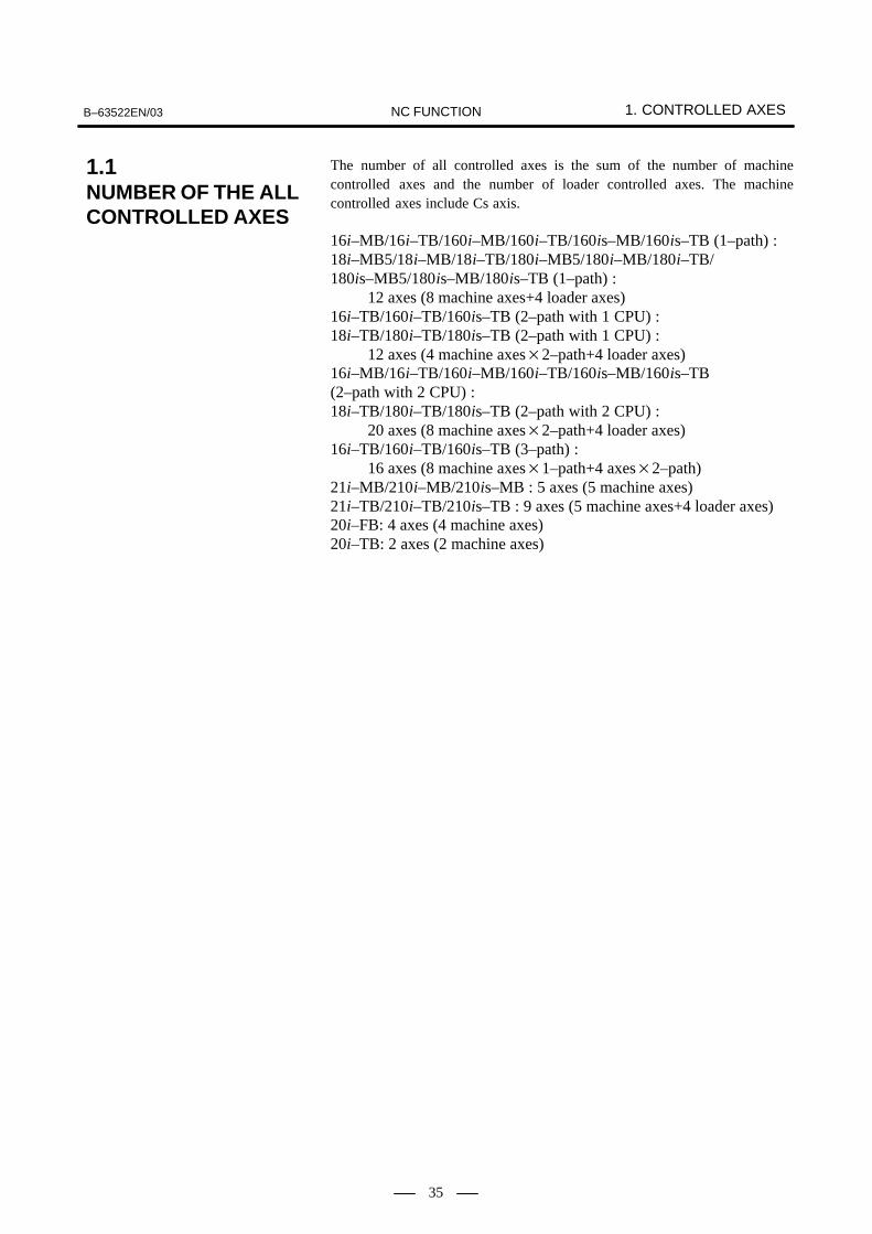
B–63522EN/03 1. CONTROLLED AXESNC FUNCTION
35
The number of all controlled axes is the sum of the number of machinecontrolled axes and the number of loader controlled axes. The machinecontrolled axes include Cs axis.
16i–MB/16i–TB/160i–MB/160i–TB/160is–MB/160is–TB (1–path) :18i–MB5/18i–MB/18i–TB/180i–MB5/180i–MB/180i–TB/180is–MB5/180is–MB/180is–TB (1–path) : 12 axes (8 machine axes+4 loader axes)16i–TB/160i–TB/160is–TB (2–path with 1 CPU) :18i–TB/180i–TB/180is–TB (2–path with 1 CPU) : 12 axes (4 machine axes�2–path+4 loader axes)16i–MB/16i–TB/160i–MB/160i–TB/160is–MB/160is–TB (2–path with 2 CPU) :18i–TB/180i–TB/180is–TB (2–path with 2 CPU) : 20 axes (8 machine axes�2–path+4 loader axes)16i–TB/160i–TB/160is–TB (3–path) : 16 axes (8 machine axes�1–path+4 axes�2–path)21i–MB/210i–MB/210is–MB : 5 axes (5 machine axes)21i–TB/210i–TB/210is–TB : 9 axes (5 machine axes+4 loader axes)20i–FB: 4 axes (4 machine axes)20i–TB: 2 axes (2 machine axes)
1.1NUMBER OF THE ALLCONTROLLED AXES

1. CONTROLLED AXES B–63522EN/03NC FUNCTION
36
Two–path control is available in 16i–MB, 16i–TB, 18i–TB, 160i–MB,160i–TB, 180i–TB, 160is–MB, 160is–TB, and 180is–TBThree–path control is available in 16i–TB, 160i–TB, and 160is–TB.In 18i–MB5, 180i–MB5, 180is–MB5, 18i–MB, 180i–MB, 180is–MB,21i–MB, 21i–TB, 210i–MB, 210i–TB, 210is–MB, 210is–TB, 20i–FB,and 20i–TB number of controlled paths is one.
16i–MB/18i–MB5/18i–MB/160i–MB/180i–MB5/180i–MB/160is–MB/180is–MB5/180is–MB/21i–MB/210i–MB/210is–MB/20i–FB (each path) :
3 axes16i–TB/18i–TB/160i–TB/180i–TB/160is–TB/180is–TB/21i–TB/210i–TB/210is–TB/20i–TB (each path) :
2 axes
16i–MB/18i–MB5/18i–MB/160i–MB/180i–MB5/180i–MB/21i–MB/210i–MB (each path) :
2 axes16i–TB/18i–TB/160i–TB/180i–TB/160is–TB/180is–TB/21i–TB/210i–TB/210is–TB/20i–TB (each path) :
2 axes20i–FB : 3 axes
16i–MB/16i–TB/160i–MB/160i–TB/160is–MB/160is–TB (1–path) :18i–MB5/18i–MB/18i–TB/180i–MB5/180i–MB/180i–TB/180is–MB5/180is–MB/180is–TB (1–path) :16i–MB/16i–TB/160i–MB/160i–TB/160is–MB/160is–TB(2–path with 2 CPU) :18i–TB/180i–TB/180is–TB (2–path with 2 CPU) :
Max. 8 axes (including Cs axis)16i–TB/160i–TB/160is–TB (3–path) :
Max. 8 axes (Including Cs axis)�1–pathMax. 4 axes (Including Cs axis)�2–path
16i–TB/160i–TB/160is–TB (2– path with 1 CPU) :18i–TB/180i–TB/180is–TB (2–path with 1 CPU) :
Max. 4 axes (including Cs axis)21i–MB/21i–TB/210i–MB/210i–TB/210is–MB/210is–TB :
Max. 5 axes (including Cs axis)20i–FB: Max. 4 axes20i–TB: Max. 2 axes
* For the multipath system, a value is indicated for each path.
1.2MACHINECONTROLLED AXES
1.2.1Number of ControlledPaths
1.2.2Number of BasicControlled Axes
1.2.3Number of BasicSimultaneouslyControlled Axes
1.2.4Number of ControlledAxes Expanded (All)

B–63522EN/03 1. CONTROLLED AXESNC FUNCTION
37
16i–MB/16i–TB/160i–MB/160i–TB/160is–MB/160is–TB (each path) :Max. 6 axes
18i–MB5/180i–MB5/180is–MB5/180is–TB : Max. 5 axes
18i–MB/18i–TB/180i–MB/180i–TB/180is–MB/180is–TB (each path) :Max. 4 axes
21i–MB/21i–TB/210i–MB/210i–TB/210is–MB/210is–TB/20i–FB : Max. 4 axes
16i–MB/16i–TB/18i–MB5//18i–MB/18i–TB/21i–MB/21i–TB/160i–MB/160i–TB/160is–MB/160i–TB/180i–MB/180i–TB/180is–MB5/180is–MB/180is–TB/210i–MB/210i–TB/210is–MB/210is–TB/20i–FB (each path) :
Max. simultaneous 4 axes (Cs axis is disable.)
16i–MB/160i–MB/160is–MB/16i–TB/160i–TB/160is–TB (at 1–path) :Up to 4 axes
18i–MB/180i–MB/180is–MB/18i–TB/180i–TB/180is–TB (at 1–path) :Up to 3 axes
21i–MB/210i–MB/210is–MB/21i–TB/210i–TB/210is–TB (at 1–path) :Up to 2 axes
16i–MB/160i–MB/160is–MB/16i–TB/160i–TB/160is–TB (at 2CPU 2–path) : Up to 4 axes for each path18i–TB/180i–TB/180is–TB (at 2CPU 2–path): Up to 3 axes for each path16i–TB/160i–TB/160is–TB/18i–TB/180i–TB/180is–TB (at 1CPU 2–path) : Up to 2 axes for each path(For 1CPU 2–path on the 18i/180i/180is, up to 3 axes are permitted forboth paths in total.)16i–TB/160i–TB/160is–TB (at 2CPU 3–path) : Up to 2 axes for each path
1.2.5Number ofSimultaneouslyControlled AxesExpanded (All)
1.2.6Axis Control by PMC
1.2.7Cs Contour Control
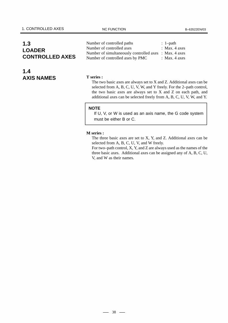
1. CONTROLLED AXES B–63522EN/03NC FUNCTION
38
Number of controlled paths : 1–pathNumber of controlled axes : Max. 4 axesNumber of simultaneously controlled axes : Max. 4 axesNumber of controlled axes by PMC : Max. 4 axes
T series :The two basic axes are always set to X and Z. Additional axes can beselected from A, B, C, U, V, W, and Y freely. For the 2–path control,the two basic axes are always set to X and Z on each path, andadditional axes can be selected freely from A, B, C, U, V, W, and Y.
NOTEIf U, V, or W is used as an axis name, the G code systemmust be either B or C.
M series :The three basic axes are set to X, Y, and Z. Additional axes can beselected from A, B, C, U, V, and W freely.For two–path control, X, Y, and Z are always used as the names of thethree basic axes. Additional axes can be assigned any of A, B, C, U,V, and W as their names.
1.3LOADERCONTROLLED AXES
1.4AXIS NAMES

B–63522EN/03 1. CONTROLLED AXESNC FUNCTION
39
There are three increment systems as shown in the tables below. One ofthe increment systems can be selected using a parameter.
NOTEIf IS-C is selected, option ”increment system 1/10” isrequired.If IS–D is selected, option “increment system 1/100” isrequired.
Table 1.5(a) IS–B
Least input incrementLeast
commandincrement
Abbreviation
Millimeter
Metric input
0.001 mm (diameter programming) 0.0005 mm
IS–B
Millimeter
Metric input 0.001 mm (radius programming) 0.001 mm
IS–B
Millimetermachine
0.001 deg 0.001 deg
IS–B
Millimetermachine
Inch input
0.0001 inch (diameter programming) 0.0005 mm
IS–B
Inch input 0.0001 inch (radius programming) 0.001 mm
IS–B0.001 deg 0.001 deg
IS–B
Inch
Metric input
0.001 mm (diameter programming) 0.00005 inchIS–B
Inch
Metric input 0.001 mm (radius programming) 0.0001 inch
Inchmachine
0.001 deg 0.001 degInchmachine
Inch input
0.0001 inch (diameter programming) 0.00005 inch
Inch input 0.0001 inch (radius programming) 0.0001 inch
0.001 deg 0.001 deg
Table 1.5(b) IS–C
Least input incrementLeast
commandincrement
Abbreviation
Millimeter
Metric input
0.0001 mm (diameter programming) 0.00005 mm
IS–C
Millimeter
Metric input 0.0001 mm (radius programming) 0.0001 mm
IS–C
Millimetermachine
0.0001 deg 0.0001 deg
IS–C
Millimetermachine
Inch input
0.00001 inch (diameter programming) 0.00005 mm
IS–C
Inch input 0.00001 inch (radius programming) 0.0001 mm
IS–C0.0001 deg 0.0001 deg
IS–C
Inch
Metric input
0.0001 mm (diameter programming) 0.000005 inchIS–C
Inch
Metric input 0.0001 mm (radius programming) 0.00001 inch
Inchmachine
0.0001 deg 0.0001 degInchmachine
Inch input
0.00001 inch (diameter programming) 0.000005 inch
Inch input 0.00001 inch (radius programming) 0.00001 inch
0.0001 deg 0.0001 deg
1.5INCREMENT SYSTEM

1. CONTROLLED AXES B–63522EN/03NC FUNCTION
40
Table 1.5(c) IS–D
Least input incrementLeast
commandincrement
Abbreviation
Millimeter
Metric input
0.00001 mm (diameter programming) 0.000005 mm
IS–D
Millimeter
Metric input 0.00001 mm (radius programming) 0.00001 mm
IS–D
Millimetermachine
0.00001 deg 0.00001 deg
IS–D
Millimetermachine
Inch input
0.000001 inch (diameter programming) 0.000005 mm
IS–D
Inch input 0.000001 inch (radius programming) 0.00001 mm
IS–D0.00001 deg 0.00001 deg
IS–D
Inch
Metric input
0.00001 mm (diameter programming) 0.0000005 inchIS–D
Inch
Metric input 0.00001 mm (radius programming) 0.000001 inch
Inchmachine
0.00001 deg 0.00001 degInchmachine
Inch input
0.000001 inch (diameter programming) 0.0000005 inch
Inch input 0.000001 inch (radius programming) 0.000001 inch
0.00001 deg 0.00001 deg
The least command increment is in millimeters or inches, depending onthe machine tool. One of them must be selected using a parameterbeforehand.The least input increment can be switched between metric input and inchinput by using a G code (G20 or G21) or a setting parameter.
The following least input increments can be set using a parameter:
Increment system Least input increment
IS–B 0.01 mm, 0.01 deg, or 0.0001 inch
IS–C 0.001 mm, 0.001 deg, or 0.00001 deg
NOTEThe minimum input increment for inch input is not affected.
1.5.1Input Unit (10 Times)

B–63522EN/03 1. CONTROLLED AXESNC FUNCTION
41
The following table lists the maximum strokes of machine tools that areallowed by the control unit:
Maximum stroke = Least command increment � 99999999
Increment system Maximum stroke
IS–B
Millimeter machine±99999.999 mm±99999.999 deg
IS–B
Inch machine±9999.9999 inch±99999.999 deg
IS–C
Millimeter machine±9999.9999 mm±9999.9999 deg
IS–C
Inch machine±999.99999 inch±9999.9999 deg
NOTE1 The values (in mm or inches) in the table are diameter
values if diameter programming is specified, or radiusvalues if radius programming is specified.
2 A command that exceeds the maximum stroke is notallowed.
1.6MAXIMUM STROKE

2. PREPARATORY FUNCTIONS B–63522EN/03NC FUNCTION
42
2 PREPARATORY FUNCTIONS

B–63522EN/03 2. PREPARATORY FUNCTIONSNC FUNCTION
43
The following G codes are provided. The G codes are classified intothree: A, B, and C. One of the G code types can be selected using aparameter. In this manual, G code system B is assumed.
G code list for T series (1/3)
G codeGroup Function
A B CGroup Function
G00 G00 G00
01
Positioning (Rapid traverse)
G01 G01 G0101
Linear interpolation (Cutting feed)
G02 G02 G0201
Circular interpolation CW
G03 G03 G03 Circular interpolation CCW
G04 G04 G04
00
Dwell
G05 G05 G05
00
High speed cycle cutting, high–speed remote buffer A
G07 G07 G07
00
Hypothetical axis interpolation
G07.1(G107)
G07.1(G107)
G07.1(G107) 00
Cylindrical interpolation
G08 G08 G08
00
Advanced preview control
G10 G10 G10 Programmable data input
G10.6 G10.6 G10.6 Tool retract and return
G11 G11 G11 Programmable data input mode cancel
G12.1(G112)
G12.1(G112)
G12.1(G112)
21
Polar coordinate interpolation mode
G13.1(G113)
G13.1(G113)
G13.1(G113)
21
Polar coordinate interpolation cancel mode
G17 G17 G17
16
XpYp plane selection
G18 G18 G18 16 ZpXp plane selection
G19 G19 G19 YpZp plane selection
G20 G20 G7006
Input in inch
G21 G21 G7106
Input in mm
G22 G22 G2209
Stored stroke check function on
G23 G23 G2309
Stored stroke check function off
G25 G25 G2508
Spindle speed fluctuation detection off
G26 G26 G2608
Spindle speed fluctuation detection on
G27 G27 G27
00
Reference position return check
G28 G28 G28
00
Return to reference position
G30 G30 G30 00 2nd, 3rd and 4th reference position return
G30.1 G30.1 G30.1 Floating reference point return
G31 G31 G31 Skip function
2.1T SERIES

2. PREPARATORY FUNCTIONS B–63522EN/03NC FUNCTION
44
G code list for T series (2/3)
G codeGroup Function
A B CGroup Function
G32 G33 G33
01
Thread cutting
G34 G34 G34
01
Variable–lead thread cutting
G35 G35 G35 01 Circular threading CW
G36 G36 G36Circular threading CCW (When the bit 3 (G36) of parameterNo. 3405 is set to 1)
G36 G36 G36
00
Automatic tool compensation X (When the bit 3 (G36) ofparameter No. 3405 is set to 0)
G37 G37 G3700
Automatic tool compensation Z
G37.1 G37.1 G37.1 00 Automatic tool compensation X
G37.2 G37.2 G37.2 Automatic tool compensation Z
G39 G39 G39 Corner circular interpolation
G40 G40 G40
07
Tool nose radius compensation cancel
G41 G41 G41 07 Tool nose radius compensation left
G42 G42 G42 Tool nose radius compensation right
G50 G92 G9200
Coordinate system setting or max. spindle speed setting
G50.3 G92.1 G92.100
Workpiece coordinate system preset
G50.2(G250)
G50.2(G250)
G50.2(G250)
20
Polygonal turning cancel
G51.2(G251)
G51.2(G251)
G51.2(G251)
20
Polygonal turning
G52 G52 G5200
Local coordinate system setting
G53 G53 G5300
Machine coordinate system setting
G54 G54 G54
14
Workpiece coordinate system 1 selection
G55 G55 G55
14
Workpiece coordinate system 2 selection
G56 G56 G5614
Workpiece coordinate system 3 selection
G57 G57 G5714
Workpiece coordinate system 4 selection
G58 G58 G58 Workpiece coordinate system 5 selection
G59 G59 G59 Workpiece coordinate system 6 selection
G60 G60 G6000
Single direction positioning
G65 G65 G6500
Macro calling
G66 G66 G6612
Macro modal call
G67 G67 G6712
Macro modal call cancel
G68 G68 G68 04 Mirror image for double turrets ON or balance cut mode
G68.1 G68.1 G68.1 17 Three–dimensional coordinate system conversion mode on
G69 G69 G69 04Mirror image for double turrets OFF or balance cut modecancel
G69.1 G69.1 G69.1 17 Three–dimensional coordinate system conversion mode off

B–63522EN/03 2. PREPARATORY FUNCTIONSNC FUNCTION
45
G code list for T series (3/3)
G codeGroup Function
A B CGroup Function
G70 G70 G72
00
Finishing cycle
G71 G71 G73
00
Stock removal in turning
G72 G72 G74
00
Stock removal in facing
G73 G73 G75 00 Pattern repeating
G74 G74 G76 End face peck drilling
G75 G75 G77 Outer diameter/internal diameter drilling
G76 G76 G78 Multiple threading cycle
G71 G71 G72
01
Traverse grinding cycle (for grinding machine)
G72 G72 G7301
Traverse direct constant–dimension grinding cycle (for grinding machine)
G73 G73 G74
01
Oscilation grinding cycle (for grinding machine)
G74 G74 G75Oscilation direct constant–dimension grinding cycle(for grinding machine)
G80 G80 G80 10 Canned cycle for drilling cancel
G80.4 G80.4 G80.400
Hobbing function synchronous cancel
G81.4 G81.4 G81.400
Hobbing function synchronous start
G83 G83 G83
10
Cycle for face drilling
G84 G84 G84
10
Cycle for face tapping
G86 G86 G8610
Cycle for face boring
G87 G87 G8710
Cycle for side drilling
G88 G88 G88 Cycle for side tapping
G89 G89 G89 Cycle for side boring
G90 G77 G20
01
Outer diameter/internal diameter cutting cycle
G92 G78 G21 01 Thread cutting cycle
G94 G79 G24 Endface turning cycle
G96 G96 G9602
Constant surface speed control
G97 G97 G9702
Constant surface speed control cancel
G98 G94 G9405
Per minute feed
G99 G95 G9505
Per rotation feed
� G90 G9003
Absolute programming
� G91 G9103
Incremental programming
� G98 G9811
Return to initial level
� G99 G9911
Return to R point level
G100 G100 G100
00
B axis control–Program registration completion
G101 G101 G101
00
B axis control–First program registration start
G102 G102 G102 00 B axis control–Second program registration start
G103 G103 G103 B axis control–Third program registration start
G110 G110 G110 B axis control–One motion operation programming

2. PREPARATORY FUNCTIONS B–63522EN/03NC FUNCTION
46
The following G codes are provided :
G code list for M series (1/4)
G code Group Function
G00
01
Positioning
G01
01
Linear interpolation
G02
01
Circular interpolation/Helical interpolation CW
G03 01 Circular interpolation/Helical interpolation CCW
G02.2, G03.2 Involute interpolation
G02.3, G03.3 Exponential function interpolation
G02.4, G03.4 Three–dimensional circular interpolation
G04
00
Dwell, Exact stop
G0500
High speed cycle machining, high–speed remote buffer A/B, high–preci-sion contour control, simple high–precision contour control
G05.1
00
AI contour/AI nano contour/AI advanced preview/Smooth interpolation
G05.4 HRV3 on/off
G06.2 01 NURBS interpolation
G07
00
Hypothetical axis interpolation
G07.1 (G107)
00
Cylindrical interpolation
G08
00
Look–ahead control
G09 00 Exact stop
G10 Programmable data input
G10.6 Tool retract and return
G11 Programmable data input mode cancel
G12.125
Polar coordinate interpolation mode
G13.125
Polar coordinate interpolation cancel mode
G1517
Polar coordinates command cancel
G1617
Polar coordinates command
G17
02
XpYp plane selection Xp: X axis or its parallel axis
G18 02 ZpXp plane selection Yp: Y axis or its parallel axis
G19 YpZp plane selection Zp: Z axis or its parallel axis
G2006
Input in inch
G2106
Input in mm
G2204
Stored stroke check function on
G2304
Stored stroke check function off
G2524
Spindle speed fluctuation detection off
G2624
Spindle speed fluctuation detection on
2.2M SERIES

B–63522EN/03 2. PREPARATORY FUNCTIONSNC FUNCTION
47
G code list for M series (2/4)
G code Group Function
G27
00
Reference position return check
G28
00
Automatic return to reference position
G29
00
Automatic return from reference position
G3000
2nd, 3rd and 4th reference position return
G30.100
Floating reference point return
G31 Skip function
G31.8 EGB skip function
G31.9 Continuous high–speed skip function
G33 01 Thread cutting
G3700
Automatic tool length measurment
G3900
Corner offset circular interpolation
G40
07
Cutter compensation cancel/three–dimensional tool compensation cancel
G41
07
Cutter compensation left/three–dimensional tool compensation
G41.207
Three–dimensional cutter compensation (Tool side compensation) left side
G41.307
Three–dimensional cutter compensation (Leading edge offset)
G42 Cutter compensation right
G42.2 Three–dimensional cutter compensation (Tool side compensation) right side
G40.1 (G150)
19
Normal direction control cancel mode
G41.1 (G151) 19 Normal direction control left side on
G42.1 (G152) Normal direction control right side on
G4308
Tool length compensation + direction
G4408
Tool length compensation – direction
G45
00
Tool offset increase
G4600
Tool offset decrease
G4700
Tool offset double increase
G48 Tool offset double decrease
G49 08 Tool length compensation cancel
G5011
Scaling cancel
G5111
Scaling
G50.122
Programmable mirror image cancel
G51.122
Programmable mirror image

2. PREPARATORY FUNCTIONS B–63522EN/03NC FUNCTION
48
G code list for M series (3/4)
G code Group Function
G5200
Local coordinate system setting
G5300
Machine coordinate system selection
G5414
Workpiece coordinate system 1 selection
G54.114
Additional workpiece coordinate system selection
G54.2 23 Rotary table dynamic fixture offset
G55
14
Workpiece coordinate system 2 selection
G56
14
Workpiece coordinate system 3 selection
G57 14 Workpiece coordinate system 4 selection
G58 Workpiece coordinate system 5 selection
G59 Workpiece coordinate system 6 selection
G60 00/01 Single direction positioning
G61
15
Exact stop mode
G6215
Automatic corner override
G6315
Tapping mode
G64 Cutting mode
G65 00 Macro call
G6612
Macro modal call
G6712
Macro modal call cancel
G6816
Coordinate rotation/three–dimensional coordinate conversion
G6916
Coordinate rotation cancel/three–dimensional coordinate conversion cancel
G72.100
Rotation copy
G72.200
Linear copy
G7309
Peck drilling cycle
G7409
Counter tapping cycle
G75 01 Plunge grinding cycle (for grinding machine)
G76 09 Fine boring cycle
G77
01
Direct constant–dimension plunge grinding cycle(for grinding machine)
G78 01 Continuous–feed surface grinding cycle(for grinding machine)
G79 Intermittent–feed surface grinding cycle(for grinding machine)

B–63522EN/03 2. PREPARATORY FUNCTIONSNC FUNCTION
49
G code list for M series (4/4)
G code Group Function
G80 09 Canned cycle cancel/external operation function cancel
G80.5 24 Synchronization start of electronic gear box (EGB) (for two axes program-ming)
G81 09 Drilling cycle, spot boring cycle or external operation function
G81.1 00 Chopping function
G81.5 24 Synchronization start of electronic gear box (EGB) (for two axes program-ming)
G82
09
Drilling cycle or counter boring cycle
G83
09
Peck drilling cycle
G84
09
Tapping cycle
G8509
Boring cycle
G8609
Boring cycle
G87 Back boring cycle
G88 Boring cycle
G89 Boring cycle
G9003
Absolute command
G9103
Increment command
G9200
Setting for work coordinate system or clamp at maximum spindle speed
G92.100
Workpiece coordinate system preset
G9405
Feed per minute
G9505
Feed per rotation
G9613
Constant surface speed control
G9713
Constant surface speed control cancel
G9810
Return to initial point in canned cycle
G9910
Return to R point in canned cycle
G16020
In–feed control function cancel(for grinding machine)
G16120
In–feed control function(for grinding machine)

3. INTERPOLATION FUNCTIONS B–63522EN/03NC FUNCTION
50
3 INTERPOLATION FUNCTIONS

B–63522EN/03 3. INTERPOLATION FUNCTIONSNC FUNCTION
51
Positioning is done with each axis separately (Non linear interpolationtype positioning).Either of the following tool paths can be selected accroding to parameter.
� Non linear interpolation positioningThe tool is positioned with the rapid traverse rate for each axisseparately. The tool path is normally straight.
� Linear interpolation posioningThe tool path is the same as in linear interpolation (G01). The tool ispositioned within the shortest possible time at a speed that is not morethan the rapid traverse rate for each axis.When the acceleration/deceleration type is changed from the constantacceleration (inclination) type to the constant time (time constant)type, the tool can move along a specified path.
Linear interpolationpositioning
Non linear interpolationpositioningEnd position
Start position
It is decelerated, to a stop at the end point, and imposition check isperformed (checks whether the machine has come to the specifiedposition). The in-position check can be suppressed using a parameter.Width of imposition can be set as a parameter.
G00 _ ;IP
3.1POSITIONING (G00)
Format
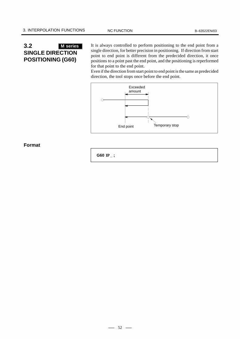
3. INTERPOLATION FUNCTIONS B–63522EN/03NC FUNCTION
52
It is always controlled to perform positioning to the end point from asingle direction, for better precision in positioning. If direction from startpoint to end point is different from the predecided direction, it oncepositions to a point past the end point, and the positioning is reperformedfor that point to the end point.Even if the direction from start point to end point is the same as predecideddirection, the tool stops once before the end point.
Exceededamount
End point Temporary stop
G60 _ ;IP
3.2SINGLE DIRECTION POSITIONING (G60)(M series)
M series
Format
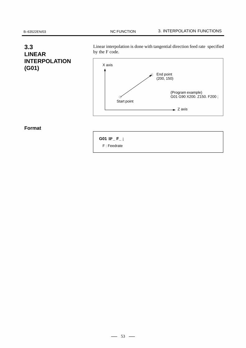
B–63522EN/03 3. INTERPOLATION FUNCTIONSNC FUNCTION
53
Linear interpolation is done with tangential direction feed rate specifiedby the F code.
Start point
End point(200, 150)
(Program example)G01 G90 X200. Z150. F200 ;
X axis
Z axis
G01 _ F_ ;IP
F : Feedrate
3.3LINEARINTERPOLATION(G01)
Format

3. INTERPOLATION FUNCTIONS B–63522EN/03NC FUNCTION
54
Circular interpolation of optional angle from 0° to 360 ° can be specified.G02: Clockwise (CW) circular interpolationG03: Counterclockwise (CCW) circular interpolation
Yp
Xp
G17
Xp
Zp
G18
Zp
Yp
G19
G02
G03
G02
G03
G02
G03
Feed rate of the tangential direction takes the speed specified by the Fcode. Planes to perform circular interpolation is specified by G17, G18,G19. Circular interpolation can be performed not only on the X, Y, andZ axis but also on the parallel axes of the X, Y, and Z axes.
G17: Xp-Yp planeG18: Zp-Xp planeG19: Yp-Zp planewhere
Xp: X axis or its parallel axis Yp: Y axis or its parallel axis Zp: Z axis or its parallel axis Parameter is set to decide which parallel axis of the X, Y, Z axes to be theadditional axis.
Arc on the Xp-Yp plane
G17G02G03
Xp_ Yp_ R_I_ J_
F_ ;
Arc on the Zp-Xp plane
G18G02G03
Zp_ Xp_ R_K_ I_
F_ ;
Arc on the Yp-Zp plane
G19G02G03
Yp_ Zp_ R_J_ K_
F_ ;
I_. J_, K_:Distance of the X, Y, Z axes from the start point to the center ofthe circle
R:Arc radius (For an arc having a central angle of 180° or greater, specifyan R value with a minus sign. A complete circumference cannot be speci-fied.)
��� �����(x, y)
Center
i
j
X
Y
Startpoint
��� �����(z, x)
Center
k
i
Z
X
Startpoint
��� �����(y, z)
Center
j
k
Y
Z
Startpoint
3.4CIRCULARINTERPOLATION(G02, G03)
Format

B–63522EN/03 3. INTERPOLATION FUNCTIONSNC FUNCTION
55
When the option for specifying arc radius R with nine digits is selectedfor the T series, the valid radius range for circular interpolation isexpanded as follows:
Without the option for specifying arc radius R with nine digits
Input increments
Metric input Inch input
Incrementsystem
IS–B 0.001 to 99999.999mm 0.0001 to 9999.9999inchsystem
IS–C 0.0001 to 9999.9999mm 0.00001 to 999.99999inch
With the option for specifying arc radius R with nine digits
Input increments
Metric input Inch input
Incrementsystem
IS–B 0.001 to 999999.999mm 0.0001 to 99999.9999inchsystem
IS–C 0.0001 to 99999.9999mm 0.00001 to 9999.99999inch

3. INTERPOLATION FUNCTIONS B–63522EN/03NC FUNCTION
56
Helical interpolation performs circular interpolation of a maximum oftwo axes, synchronizing with other optional two axes circularinterpolation. Thread cutting of large radius threads or machining of solidcams are possible by moving a tool in a spiral. The commanded speed is the speed of the tangential direction of the arc.Thus, the speed of a linear axis is expressed as follows:
F �Lengthoflinearaxis
Arclength
Z
X Y
Tool path
Tangential speed along an arc by circular interpolationis the rate specified in programming.
Arc on the Xp-Yp plane
α_ (β_) F_ ;
Arc on the Zp-Xp plane
α_ (β_) F_ ;
Arc on the Yp-Zp plane
α_ (β_) F_ ;
α, β: Optional axis other than the circular interpolation axes
G17G02G03
Xp_ Yp_ R_I_ J_
G18G02G03
Zp_ Xp_ R_K_ I_
G19G02G03
Yp_ Zp_ R_J_ K_
3.5HELICALINTERPOLATION(G02, G03)
Format

B–63522EN/03 3. INTERPOLATION FUNCTIONSNC FUNCTION
57
Helical interpolation B moves the tool in a helical manner. Thisinterpolation can be executed by specifying the circular interpolationcommand together with up to four additional axes in simplehigh–precision contour control mode.
Basically, the command can be specified by adding two movement axesto a standard helical interpolation command (see Section 3.5). AddressF should be followed by a tangential velocity, which has been determinedby also taking movement along the linear axes into consideration.
Z
X Y
Tool path
The feedrate equals the tangential velocity determinedby also taking movement along the linear axes intoconsideration.
G17G02
G03Xp_ Yp_
I_ J_R_ α� β� γ� δ� �� �
G18G02
G03Zp_ Xp_
I_ K_R_ α� β� γ� δ� �� �
G19G02
G03Yp_ Zp_
J_ K_R_ α� β� γ� δ� �� �
With an arc in the Xp–Yp plane
With an arc in the Zp–Xp plane
With an arc in the Yp–Zp plane
α� β� γ� δ� Any axis to which circular interpolation is notapplied. Up to four axes can be specified.
3.6HELICALINTERPOLATION B(G02, G03) (M series)
M series
Format

3. INTERPOLATION FUNCTIONS B–63522EN/03NC FUNCTION
58
The function in which contour control is done in converting the commandprogrammed in a cartesian coordinate system to the movement of a linearaxis (movement of a tool) and the movement of a rotary axis (rotation ofa workpiece) is the polar coordinate interpolation. It is an effectivefunction when a straight line groove is cut on the outer diameter of aworkpiece or when a cam shaft is ground.Whether the polar coordinate interpolation is done or not is commandedby a G code.These G codes shall be commanded in a single block.
G12.1; Polar coordinate interpolation mode (Polar coordinate interpolation shall be done.)
G13.1; Polar coordinate interpolation cancel mode (Polar coordinate interpolation is not done.)
The axes (linear axis and rotary axis) on which polar coordinateinterpolation is done are set beforehand by parameters. Change the mode to polar coordinate interpolation mode by commandingG12.1, and a plane (hereinafter referred to as polar coordinateinterpolation plane) is selected in which linear axis is made to the firstaxis of the plane, and virtual axis being a right angle with the linear axisis made to the second axis of the plane. Polar coordinate interpolation iscarried out on this plane.In the polar coordinate interpolation made, the command of linearinterpolation (G01) and circular interpolation (G02, G03) is possible.And both absolute command (G90) and incremental command (G91) arepossible. For the program command it is possible to apply cutter compensation.For the path after cutter compensation is done, polar coordinateinterpolation can be made. As for feedrate, specify the tangential speed (relative speed between theworkpiece and the tool) on the polar coordinate interpolation plane(cartesian coordinate system) with F.
The polar coordinate interpolation cancel mode is obtained by G13.1command.
3.7POLAR COORDINATEINTERPOLATION(G12.1, G13.1)
Format
Explanations
� Polar coordinateinterpolation mode(G12.1)
� Polar coordinateinterpolation cancelmode (G13.1)

B–63522EN/03 3. INTERPOLATION FUNCTIONSNC FUNCTION
59
N204
N205
N206
N203
N202 N201
N208
N207
N200
Tool
C′ (Virtual axis)
X axis
Z axis
C axis Path after cuttercompensation
Programmed path
(X axis is diameter programming and C axis is radius programming)
00001;
:
N100 G90 G00 X120.0 C0 Z_ ;
N200 G12.1;
N201 G42 G01 X40.0 F D01;
N202 C10.0;
N203 G03 X20.0 C20.0 R10.0 ;
N204 G01 X-40.0 ;
N205 G-10.0 ;
N206 G03 X-20.0 C-20.0 I10.0 K0 ;
N207 G01 X40.0 ;
N208 C0 ;
N209 G40 X120.0 ;
N210 G13.1 ;
N300 Z_ ;
N400 X_ C_ ;
:
M30 ;
Contour program
(Program in cartesian coordinate system of X-C′ plane)
Canceling polar coordinateinterpolation
Positioning to the starting position
Starting polar coordinate interpolation
Examples
� Polar coordinateinterpolation by X axis(Linear axis) and C axis(Rotary axis)

3. INTERPOLATION FUNCTIONS B–63522EN/03NC FUNCTION
60
When the form on the expanded side view of a cylinder (from on thecylinder coordinate system) is commanded by a program command, theNC converts the form into a linear axis movement and a rotary axismovement then performs a contour control. This feature is called thecylindrical interpolation.Cylindrical interpolation is commanded with G07.1.
G07.1 (Name of rotary axis) Radius value of cylinder ; Cylindrical interpolation mode
G07.1 (Name of rotary axis) 0 ;Cancellation mode of cylindrical interpolation
Cylindrical interpolation is made between the rotary axis specified in theblock of G07.1 and the other optional linear axis. Circle interpolation command is allowed as well as linear interpolation,during cylindrical interpolation mode. Also, absolute command andincremental command can be made. Cutter compensation can be addedto the program command. Cylindrical interpolation is made for the pathafter cutter compensation. Feed rate gives the tangential speed on the expanded plane of the cylinderwith F.
G07.1 (Name of rotary axis) 0; Cancellation mode of cylindricalinterpolation is made when commanded as above.
3.8CYLINDRICALINTERPOLATION(G07.1)
Format
Explanations
� Cylindrical interpolationmode
� Cancellation mode ofcylindrical interpolation

C2301901500
mm
Z
deg
110
90
70
120
30 60 70 270
N05
N06
N07
N08 N09 N10
N11
N12 N13
360
60
B–63522EN/03 3. INTERPOLATION FUNCTIONSNC FUNCTION
61
An example of a program O0001 (CYLINDRICAL INTERPOLATION);
N1 G00 G00 Z100.0 C0; N2 G01 G18 Z0 C0; N3 G7.1 C57299; N4 G01 G42 Z120.0 D10 F250; N5 G40.0; N6 G02 Z90.0 C60.0 R30.0 ;N7 G01 Z70.0; N8 G03 Z60.0 C70.0 R10.0; N9 G01 C150.0;N10 G03 Z70.0 C190.0 R75.0; N11 G01 Z110.0 C230.0;N12 G02 Z120.0 C270.0 R75.0;N13 G01 G360.0; N14 G40 Z100.0; N15 G07.1 C0; N16 M30;
Examples
Z
C
R

3. INTERPOLATION FUNCTIONS B–63522EN/03NC FUNCTION
62
The conventional cylindrical interpolation function controls the toolcenter so that the tool axis always moves along a specified path on thecylindrical surface, towards the rotation axis (cylindrical axis) of theworkpiece. On the other hand, this function controls the tool so that thetangents to the tool and a contour figure cutting surface always passthrough the rotation center of a workpiece.This function is enabled in AI high–precision contour control mode or AInano–precision contour control mode.
G05 P10000 ; (AI high–precision contour control mode ON):
G07.1 IPr ; Sets cylindrical interpolation mode : (enables cylindrical interpolation). :
G07.1 IP0 ; Clears cylindrical interpolation mode.
G05 P0 ; (AI high–precision contour control mode OFF)
IP : One rotation axis addressr : Cylinder radius of rotation axisSpecify each of G07.1 IPr; and G07.1 IP0; singly in a block.
G107 can not be used.
As shown in Fig.3.9 (a), control is exercised along the offset axis (Y–axis)direction that is perpendicular to the tool, tool center axis, and workpiecerotation center axis.
RotationaxisWorkpiece
Rotationaxis
Tool
Tool center
Y–axis Y–axis
Conventional Cylindrical interpolation basedon this function
Fig.3.9 (a) Comparison with Conventional Interpolation
3.9CYLINDRICALINTERPOLATIONCUTTING POINTCOMPENSATION(G07.1) (M series)
M series
Format
Explanation
� Comparison withconventional cylindricalinterpolation

B–63522EN/03 3. INTERPOLATION FUNCTIONSNC FUNCTION
63
The sample program below indicates the positional relationships betweena workpiece and tool.O0001(CYLINDRICAL INTERPOLATION1) ;N01 G00 G90 Z100.0 C0 ;N02 G01 G91 G19 Z0 C0 ;N03 G07.1 C57299 ;N04 G01 G42 G90 Z120.0 D01 F250. ; (1). . . N05 C20.0 ; (2). . . N06 G02 Z110.0 C60.0 R10.0 ; (3). . . N07 G01 Z100.0 ; (4). . . N08 G03 Z60.0 C70.0 R40.0 ; (5). . .
:M30 ;
Z–axis
C–axis on the cylindrical surface
Tool center path
Programmed path
Tool
20 30 60 70 ( deg )
30
60708090
120
(mm)
C–axis on theCylindricalsurface
Z–axis
Tool
(1) (2) (3)(4)
(5)
Fig.3.9 (b) Path of Sample Program for Cylindrical Interpolation Cutting Point Compensation
Example
� Example of cylindricalinterpolation cuttingpoint compensation

3. INTERPOLATION FUNCTIONS B–63522EN/03NC FUNCTION
64
Tool
Workpiece
Positional relationship between theworkpiece and tool of (5)
Positional relationship between theworkpiece and tool of (3) and (4).
WorkpieceRotationaxis Rotation
Tool
Tool center
Y–axis Y–axis
Positional relationship between theworkpiece and tool of (1)
Positional relationship between theworkpiece and tool of (2)
Cutting surface20�0�0�
Rotation Rotation
Tool center
Y–axis Y–axis
70�60�60�20�
Cutting surface
Fig.3.9 (c) Positional Relationships between Workpiece and Tool of Sample Program

B–63522EN/03 3. INTERPOLATION FUNCTIONSNC FUNCTION
65
With the following command, the involute curve machining can beperformed. Approximate involute curve with a minute straight line or arcis not needed. Therefore, the programming becomes simple and reducesthe tape length. The distribution of the pulse will not be interruptedduring the continuous minute block high speed operation, so fast, smoothinvolute curve machining is possible.
(I, J)
Start point
End point(X, Y)
Basiccircle
R
Clockwise involute interpolation
End point(X, Y)
Basiccircle
R(I, J)
Start point
Counterclockwise involute interpolation
Xp–Yp plane
G17G02.2G03.2 Xp_ Yp_ I_ J_ R_ F_ ;
G02.2 : Clockwise involute interpolation
G03.2 : Counterclockwise involute interpolation
Xp, Yp, Zp : End point coordinate value
I, J, K : Distance to the center of the basic circle of the involute curve from start point
R : Radius of basic circle
F : Cutting feedrate
Zp–Xp plane
G18 Zp_ Xp_ K_ I_ R_ F_ ;
Yp–Zp plane
G19 Yp_ Zp_ J_ K_ R_ F_ ;
G02.2G03.2
G02.2G03.2
3.10INVOLUTEINTERPOLATION(G02.2, G03.2)(M series)
M series
Format

3. INTERPOLATION FUNCTIONS B–63522EN/03NC FUNCTION
66
The involute interpolation automatic feedrate control function applies thefollowing two types of override automatically to a specified feedrateduring involute interpolation to cut more precise, better surfaces:
� Override when inner offsetting is performed in cutter compensation
� Override near the basic circle
(a) Override when inner offsetting is performed in cutter compensation
When cutter compensation is applied to involute interpolation, thefeedrate is controlled so that the speed in the direction tangent to thepath of the center of the tool (the tool center path) in normal involuteinterpolation becomes a specified feedrate.
Then, the speed of the tool periphery (the cutting point) along theprogrammed path that is the actual cutting speed changes as thecurvature of the involute curve changes every moment.
In particular, when the tool is offset to the inner side of the involutecurve, the actual cutting speed becomes higher than the specifiedfeedrate as the tool gets closer to the basic circle.
For smooth machining, the actual cutting speed should be controlledso that it matches a specified feedrate. This function calculates anappropriate override value for the momentarily changing curvature ofthe involute curve during involute interpolation particularly when aninner offset is used, so that the actual cutting speed which is thetangential speed at the cutting point is always the specified feedrate.
Programmed pathTool center path
Tool
Cutting point
Basic circle
(b) Override near the basic circle
In an area near the basic circle, the change in curvature of the involutecurve is relatively large. If such an area is cut at a programmedfeedrate, a heavy load is applied to the cutter, which may prevent agood cut surface from being produced.
In an area near the basic circle where the change in curvature of theinvolute curve is relatively large, this function decelerates the toolmovement automatically according to the parameter setting to reducethe cutter load, allowing a good cut surface to be obtained.
3.10.1Involute InterpolationAutomatic FeedrateControl Function (Mseries)
M series

B–63522EN/03 3. INTERPOLATION FUNCTIONSNC FUNCTION
67
In synchronization with the travel of the rotary axis, the linear axis (Xaxis) performes the exponential function interpolation. With the otheraxes, the linear interpolation the X axis is performed.This function is effective for the tapered constant helix machining in thetool grinding machine.This function is the best for the fluting with the end mill etc. and grinding.
X (Linear axis)
A (Rotary axis)
∆X
∆A
Z
X
A
X
U
r
I
B
J
Tapered constant helix machining
3.11EXPONENTIALFUNCTIONINTERPOLATION(G02.3, G03.3)(M series)
M series

3. INTERPOLATION FUNCTIONS B–63522EN/03NC FUNCTION
68
Positive rotation (ω=0)
G02.3 X_Y_ Z_ I_ J_ K_ R_ F_ Q_ ;
Negative rotation (ω=1)
G03.3 X_Y_ Z_ I_ J_ K_ R_ F_ Q_ ;
X_ : Command terminal point by Absolute or incremental
Y_ : Command terminal point by Absolute or incremental
Z_ : Command terminal point by Absolute or incremental
I_ : Command of angle I (The command unit is 0.001 deg. The range of command is 1 to ±89deg)
J_ : Command of angle J (The command unit is 0.001 deg. The range of command is 1 to ±89deg)
K_ : Amount of division of the linear axis in the exponential function interpolation (amount of span). The command range is a positive value.)
R_ : Command of constant value R in the exponential function interpolation.
F_ : Command of initial feed rate.The command is the same as the normal F code. The feed rateshall be given by the synthesized speed including the rotary axis.
Q_ : Command of feed rate at terminal point.The command unit is based on the reference axis. Within the CNC, the tool is interpolated between the initial feed rate (F_) and final feed rate (Q_) depending on the amount of linear axis travel.
The exponential function relation expression between the linear axis andthe rotary axis is defined as in the following :
X(�) � R � (e�
K–1) � 1tan(I)
A(�) � (–1)� � 360 ��
2�
K= ��� �
��� ��
ω=0 or 1
R, I, J are constant and θ is the angle (radian) of rotation.Also from the equation (1),
�(X) � K � �n {X � tan(I)
R� 1}
Travel of linear axis (1). . . . .
Travel of rotation axis (2). . . . .
Thus, when the tool moves from X1 to X2 along the linear axis, the anglemoved about the rotation axis is calculated as follows:
�� � K � {�n (X2 � tan(I)
R� 1) ��n (
X1 � tan(I)R
� 1) }
Specify formulas (1) and (2) in commands using the format describedabove.
Format
Explanations

B–63522EN/03 3. INTERPOLATION FUNCTIONSNC FUNCTION
69
Either of two types of machining can be selected, depending on theprogram command.� For those portions where the accuracy of the figure is critical, such as
at corners, machining is performed exactly as specified by the programcommand.
� For those portions having a large radius of curvature where a smoothfigure must becreated, points along the machining path areinterpolated with a smooth curve, calculated from the polygonal linesspecified with the program command (smooth interpolation).
In smooth interpolation mode, the CNC automatically determines,according to the program command, whether an accurate figure isrequired, such as at corners, or a smooth figure is required where theradius of curvature is large. If a block specifies a travel distance ordirection which differs greatly from that in the preceding block, smoothinterpolation is not performed for that block. Linear interpolation isperformed exactly as specified by the program command. Programmingis thus very simple.
Interpolated by smooth curve
Interpolated by smooth curve
N17
N16
N1
N2
N15 N14 N13 N12N11
N10
N9
N3 N4 N5 N6 N7
N8
Linear interpolation
Linear interpolation
N17
N16
N1
N2
N15 N14 N13 N12N11
N10
N9
N3 N4 N5 N6 N7
N8
Smooth interpolation can be specified in high–speed contour controlmode (between G05 P10000 and G05 P0). For details of high–speedcontour control, see Section 20.6.
Starting of smooth interpolation mode
G05.1 Q2X0Y0Z0;
Cancelation of smooth interpolation mode
G05.1 Q0;
3.12SMOOTHINTERPOLATION(G05.1) (ONLY AT 1–PATHCONTROL) (M series)
M series
Examples
Format

3. INTERPOLATION FUNCTIONS B–63522EN/03NC FUNCTION
70
In helical interpolation, when pulses are distributed with one of thecircular interpolation axes set to a hypothetical axis, sine interpolation isenable. When one of the circular interpolation axes is set to a hypothetical axis,pulse distribution causes the speed of movement along the remaining axisto change sinusoidally. If the major axis for threading (the axis alongwhich the machine travels the longest distance) is set to a hypotheticalaxis, threading with a fractional lead is enabled. The axis to be set as thehypothetical axis is specified with G07.
Y
r
0 Z
1
2�
� 2�
G07 � 1; Hypothetical axis cancel
G07 � 0; Hypothetical axis setting
Where, � is any one of the addresses of the controlled axes.
3.13HYPOTHETICAL AXISINTERPOLATION(G07)
Format

B–63522EN/03 3. INTERPOLATION FUNCTIONSNC FUNCTION
71
Spiral interpolation is enabled by specifying the circular interpolationcommand together with a desired number of revolutions or a desiredincrement (decrement) for the radius per revolution.Conical interpolation is enabled by specifying the spiral interpolationcommand together with one or two additional axes of movement, as wellas a desired increment (decrement) for the position along the additionalaxes per spiral revolution.Spiral interpolation and conical interpolation do not support bell–shapedacceleration/deceleration after interpolation for cutting feed.
�
�
�
�
�
3.14SPIRALINTERPOLATION,CONICALINTERPOLATION (Mseries)
M series
� Spiral interpolation
� Conical interpolation

3. INTERPOLATION FUNCTIONS B–63522EN/03NC FUNCTION
72
G17G02G03 X_ Y_ I_ J_ Q_ L_ F_ ;
X,Y,Z : Coordinates of the end point
L : Number of revolutions (positive value without a decimal point)
Q : Radius increment or decrement per spiral revolution
I, J, K : Signed distance from the start point to the center (same as the distance specified for circular interpolation)
F : Feedrate
G18G02G03 Z_ X_ K_ I_ Q_ L_ F_ ;
G19G02G03 Y_ Z_ J_ K_ Q_ L_ F_ ;
Xp–Yp plane
Zp–Xp plane
Yp–Zp plane
G17G02G03 X_ Y_ Z_ I_ J_ K_ Q_ L_ F_ ;
X,Y,Z : Coordinates of the end pointL : Number of revolutions (positive value without a decimal point)Q : Radius increment or decrement per spiral revolutionI, J, K : Two of the three values represent a signed vector from the start
point to the center. The remaining value is a height increment or decrement per spiral revolution in conical interpolationWhen the Xp–Yp plane is selected:The I and J values represent a signed vector from the start point to the center.The K value represents a height increment or decrement per spiral revolution.
F : Feedrate (determined by taking movement along the linear axes into consideration)
G18G02G03 Z_ X_ Y_ K_ I_ J_ Q_ L_ F_ ;
G19G02G03 Y_ Z_ X_ J_ K_ I_ Q_ L_ F_ ;
Xp–Yp plane
Zp–Xp plane
Yp–Zp plane
Format
� Spiral interpolation
� Conical interpolation
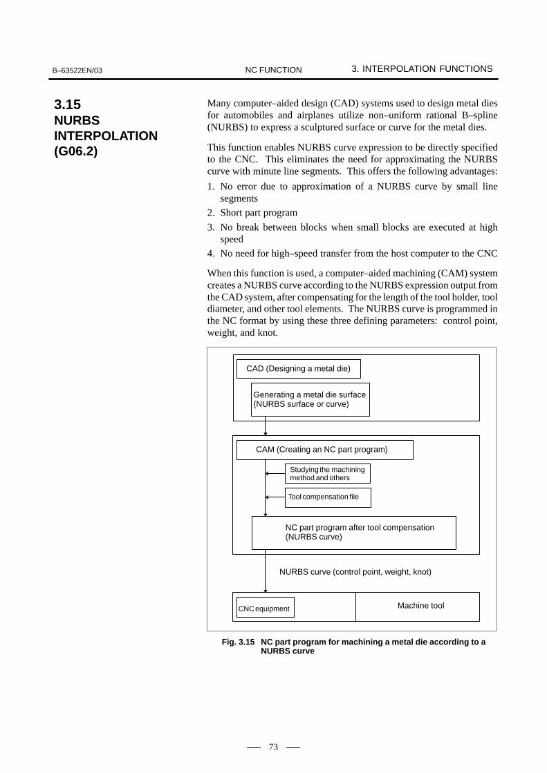
B–63522EN/03 3. INTERPOLATION FUNCTIONSNC FUNCTION
73
Many computer–aided design (CAD) systems used to design metal diesfor automobiles and airplanes utilize non–uniform rational B–spline(NURBS) to express a sculptured surface or curve for the metal dies.
This function enables NURBS curve expression to be directly specifiedto the CNC. This eliminates the need for approximating the NURBScurve with minute line segments. This offers the following advantages:
1. No error due to approximation of a NURBS curve by small linesegments
2. Short part program
3. No break between blocks when small blocks are executed at highspeed
4. No need for high–speed transfer from the host computer to the CNC
When this function is used, a computer–aided machining (CAM) systemcreates a NURBS curve according to the NURBS expression output fromthe CAD system, after compensating for the length of the tool holder, tooldiameter, and other tool elements. The NURBS curve is programmed inthe NC format by using these three defining parameters: control point,weight, and knot.
CAD (Designing a metal die)
Generating a metal die surface(NURBS surface or curve)
CAM (Creating an NC part program)
Studying the machining method and others
Tool compensation file
NC part program after tool compensation(NURBS curve)
NURBS curve (control point, weight, knot)
CNC equipment Machine tool
Fig. 3.15 NC part program for machining a metal die according to a NURBS curve
3.15NURBSINTERPOLATION(G06.2)

3. INTERPOLATION FUNCTIONS B–63522EN/03NC FUNCTION
74
NURBS interpolation must be specified in high–precision contourcontrol mode (between G05 P10000 and G05 P0). The CNC executesNURBS interpolation while smoothly accelerating or decelerating themovement so that the acceleration on each axis will not exceed theallowable maximum acceleration of the machine. In this way, the CNCautomatically controls the speed in order to prevent excessive strain beingimposed on the machine.
G05 P10000 ; (Start high–precision contour control mode)
...G06.2 [P_] K_ X_ Y_ Z_ [R_ ] [F_ ] ;
K_ X_ Y_ Z_ [R_ ] ;K_ X_ Y_ Z_ [R_ ] ;K_ X_ Y_ Z_ [R_ ] ;...K_ X_ Y_ Z_ [R_ ] ;K_ ;...K_ ;
G01 ......G05 P0 ; (End high–precision contour control mode)
G06.2 : Start NURBS interpolation modeP_ : Rank of NURBS curveX_ Y_ Z_ : Control pointR_ : WeightK_ : KnotF_ : Feedrate
Format
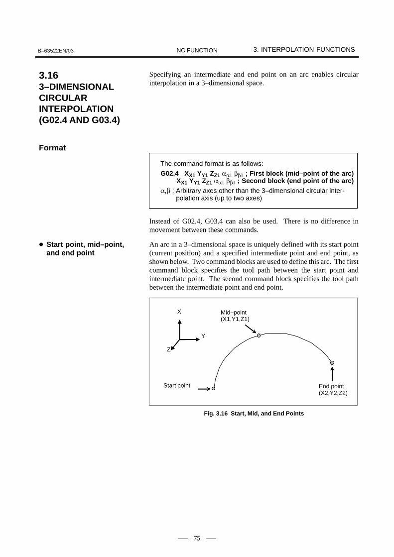
B–63522EN/03 3. INTERPOLATION FUNCTIONSNC FUNCTION
75
Specifying an intermediate and end point on an arc enables circularinterpolation in a 3–dimensional space.
The command format is as follows:
G02.4 XX1 YY1 ZZ1 αα1 ββ1 ; First block (mid–point of the arc)XX1 YY1 ZZ1 αα1 ββ1 ; Second block (end point of the arc)
α,β : Arbitrary axes other than the 3–dimensional circular inter-α,β : polation axis (up to two axes)
Instead of G02.4, G03.4 can also be used. There is no difference inmovement between these commands.
An arc in a 3–dimensional space is uniquely defined with its start point(current position) and a specified intermediate point and end point, asshown below. Two command blocks are used to define this arc. The firstcommand block specifies the tool path between the start point andintermediate point. The second command block specifies the tool pathbetween the intermediate point and end point.
X
Y
Z
Start point
Mid–point(X1,Y1,Z1)
End point(X2,Y2,Z2)
Fig. 3.16 Start, Mid, and End Points
3.163–DIMENSIONALCIRCULARINTERPOLATION(G02.4 AND G03.4)
Format
� Start point, mid–point,and end point

4. THREAD CUTTING B–63522EN/03NC FUNCTION
76
4 THREAD CUTTING

B–63522EN/03 4. THREAD CUTTINGNC FUNCTION
77
By feeding the tool synchronizing with the spindle rotation, threadcutting of the specified lead is performed. In addition to straight threads,taper threads and scroll threads can be cut with equal leads.
L
Straight thread
Taper thread
Scroll thread
L L
F_ : Lead along the long axis (axis having the largest amount of travel)
G33 _ F_ :IP
To form a single thread, threading is generally performed several timesfrom rough machining to finish machining along the same path.Threading starts when the one-revolution signal from the position coderattached to the spindle is detected. So threading always starts at the samepoint on the circumference of the workpiece, and threading is performedalong the same path on the workpiece. In this case, however, the shaftmust rotate at a constant speed during operations from rough machiningto finish machining. If the spindle speed changes, an accurate thread maynot be produced.The following shows the specifiable lead range:
Specifiable lead range
Metric input F1 to F50000 (0.01 to 500.00mm)
Inch input F1 to F99999 (0.0001 to 9.9999inch)
Specifiable lead range
Metric input 0.0001 to 500.0000mm
Inch input 0.000001 to 9.999999inch
NOTELeads exceeding the maximum cutting feed speed whenconverted to per minute feed speed cannot be specified.
4.1EQUAL LEAD THREAD CUTTING (G33) (WITH G CODE SYSTEM A: G32)
Format
Explanations
� M series
� T series

4. THREAD CUTTING B–63522EN/03NC FUNCTION
78
Multiple–thread screws
_ : End pointF_ : Lead in longitudinal directionQ_ : Threading start angle
Constant–lead threading
G33 _ F_ Q_ ;
G33 _ Q_ ;
IP
IP
IP
Variable lead thread cutting can be done by commanding long axisdirection lead and lead increase/decrease per spindle rotation.
F_ : Long axis direction lead at start point
K_ : Lead increase/decrease per spindle rotation
G34 _ F_ K_ :IP
Command value range of lead increase/decrease (K) per spindle rotation:
Metric input ±0.0001 to ±500.0000 mm/rev
Inch input ±0.000001 to ±9.999999 inch/re
4.2MULTIPLE–THREADCUTTING (G33) (T series)
T series
Format
4.3VARIABLE LEAD THREAD CUTTING (G34) (T series)
T series
Format

B–63522EN/03 4. THREAD CUTTINGNC FUNCTION
79
Continuous thread cutting in which thread cutting command block iscontinuously commanded is available. As it is controlled so that thespindle synchronism shift (occurred when shifting from one block toanother) is kept to a minimum, special threads like threads which leadsor shape change during the cycle can also be cut.
G33
G33
G33
Using the G35 and G36 commands, a circular thread, having the specifiedlead in the direction of the major axis, can be machined.
L
Circular thread
G35 : Clockwise circular threading commandG36 : Counterclockwise circular threading command
X (U) : Specify the arc end point (in the same way as for G02,G03).
Z (W)
I, K : Specify the arc center relative to the start point, usingrelative coordinates (in the same way as for G02, G03).
R : Specify the arc radius.F : Specify the lead in the direction of the major axis.Q : Specify the shift of the threading start angle (0 to 360°
in units of 0.001°)
G35G36
X (U) _ Z (W) _ F _ Q _I _ K _R _ _ _
4.4CONTINUOUSTHREAD CUTTING(T series)
T series
4.5CIRCULARTHREADING (G35, G36) (T series)
T series
Format

5. FEED FUNCTIONS B–63522EN/03NC FUNCTION
80
5 FEED FUNCTIONS

B–63522EN/03 5. FEED FUNCTIONSNC FUNCTION
81
Positioning of each axis is done in rapid motion by the positioningcommand (G00).There is no need to program rapid traverse rate, because the rates are setin the parameter (per axis).
Least command increment Rapid traverse rate range
0.001mm, deg 30 to 240000mm/min, deg/min
0.0001mm, deg 30 to 100000mm/min, deg/min
0.0001inch 3.0 to 9600.0inch/min
0.00001inch 3.0 to 4000.0inch/min
NOTEThe above feed rates are limits according to the NC’sinterpolation capacity when the high-resolution detectioninterface is equipped. When the whole system isconsidered, there are also limits according to the servosystem. For details, refer to Appendix A.
5.1RAPID TRAVERSE

5. FEED FUNCTIONS B–63522EN/03NC FUNCTION
82
Feed rates of linear interpolation (G01), and circular interpolation (G02,G03) are commanded with numbers after the F code.
In cutting feed, it is controlled so that speed of the tangential direction isalways the same commanded speed.
Cutting feed rate upper limit can be set as parameters. If the actual cuttingfeed rate (feed rate with override) is commanded exceeding the upperlimit, it is clamped to a speed not exceeding the upper limit.
With the per minute feed mode G94, tool feed rate per minute is directlycommanded by numerical value after F.
Least command increment Cutting feed rate range
0.001mm, deg 1 to 240000mm/min, deg/min
0.0001mm, deg 1 to 100000mm/min, deg/min
0.0001inch 0.01 to 9600.0inch/min
0.00001inch 0.01 to 4000.0inch/min
NOTEThe above feed rates are limits according to the NC’sinterpolation capacity. When the whole system isconsidered, there are also limits according to the servosystem. For details, see Appendix A.
5.2CUTTING FEED RATE
5.2.1Tangential SpeedConstant Control
5.2.2Cutting Feed RateClamp
5.2.3Per Minute Feed (G94)(G98 for G–codeSystem A)

B–63522EN/03 5. FEED FUNCTIONSNC FUNCTION
83
With the per revolution feed mode G95, tool feed rate per revolution ofthe spindle is directly commanded by numeral after F. A position codermust be mounted on the spindle.For the T series, however, the feed–per–revolution command can beenabled by setting the corresponding parameter accordingly, even whenthe position coder is not installed (feed per revolution without positioncoder).
Least command increment Cutting feed rate range
0.001mm, deg 0.01 to 500.00mm/rev, deg/rev
0.0001mm, deg 0.01 to 500.00mm/rev, deg/rev
0.0001inch 0.0001 to 9.9999inch/rev
0.00001inch 0.0001 to 9.9999inch/rev
Least command increment Cutting feed rate range
0.001mm, deg 0.0001 to 500.0000mm/rev, deg/rev
0.0001mm, deg 0.0001 to 500.0000mm/rev, deg/rev
0.0001inch 0.000001 to 9.999999inch/rev
0.00001inch 0.000001 to 9.999999inch/rev
NOTEThe above feed rates are limits according to the CNC’sinterpolation capacity. When the whole system isconsidered there are also limits according to the servosystem. For details, See Appendix A.
Inverse time feed mode is commanded by G93, and inverse time by Fcode. Inverse time is commanded with the following value in a 1/minunit.
In linear interpolation F= Speed/distanceIn circular interpolation F= Speed/radius
When F0 is commanded, alarm occurs.
When a 1-digit number from 1 to 9 is commanded after the F, the presetspeed corresponding the 1-digit number commanded is set as feed rate.When F0 is commanded, rapid traverse is set.Set the F1-digit feed rate change input signal on from the machine side,and rotate the manual pulse generator. Feed rate of the currently selectedspeed can be changed. Feed rate set or changed will be memorized even after power is turnedoff.
5.2.4Per Revolution Feed(G95) (G99 for G–codeSystem A)
� M series
� T series
5.2.5Inverse Time Feed(G93) (M series)
M series
5.2.6One–digit F Code Feed(M series)
M series

5. FEED FUNCTIONS B–63522EN/03NC FUNCTION
84
The per minute feed (G94) and per rotation feed (G95) can be overridedby:
0 to 254% (per every 1%). In inverse time, feed rate converted to per minute feed is overridden. Feedrate override cannot be performed to F1-digit feed. Feed rate also cannot be performed to functions as thread cutting andtapping in which override is inhibited.
Cutting feed rate can be overrided by:0 to 254% (per every 1%)
A second override can be performed on feed rats once overrided. No override can be performed on functions as thread cutting and tappingin which override is inhibited. This function is used for controlling feed rate in adaptive control, etc.
Rapid traverse rate can be overridden by: F0, 25%, 50%, 100%.
F0: A constant speed per axis is set by parameter An override of 0% to 100% can be applied in 1% steps using a signal.
Feed rate override and the second feed rate override can be clamped to100% by a signal from the machine side.
The manual continuous feedrate and incremental feed rate can beoverridden by:0% to 655.34% (in steps of 0.01%)
5.3OVERRIDE
5.3.1Feed Rate Override
5.3.2Second Feed RateOverride
5.3.3Rapid TraverseOverride
5.3.4Override Cancel
5.3.5Jog Override

B–63522EN/03 5. FEED FUNCTIONSNC FUNCTION
85
Acceleration and deceleration is performed when starting and endingmovement, resulting in smooth start and stop.Automatic acceleration/deceleration is also performed when feed ratechanges, so change in speed is also smoothly done.
Rapid traverse : Linear acceleration/deceleration (time constant is parameter set per axis)
Cutting feed : Exponential acceleration/deceleration (time constant is parameter set per axis)
Jogging : Exponential acceleration/deceleration (time constant is parameter set per axis)
Rapid traverse
0
0
TR
FR
TR
TC TC
FJ
FC
TJ TJ
FL0Time
Time
Feed, Dry run
FR : Rapid traverse
TR : Acceleration/deceleration time constant
FJ : Jog feed rate
TJ : Jog feed timeconstant
FL : Low feed rate afterdeceleration
FC : Feed rate
TC : Acceleration/deceleration time constant
Time
Jog feed
5.4AUTOMATICACCELERATION/DECELERATION
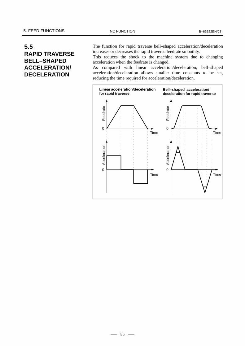
5. FEED FUNCTIONS B–63522EN/03NC FUNCTION
86
The function for rapid traverse bell–shaped acceleration/decelerationincreases or decreases the rapid traverse feedrate smoothly.This reduces the shock to the machine system due to changingacceleration when the feedrate is changed.As compared with linear acceleration/deceleration, bell–shapedacceleration/deceleration allows smaller time constants to be set,reducing the time required for acceleration/deceleration.
Linear acceleration/decelerationfor rapid traverse
0
0
Time0
0
Bell–shaped acceleration/deceleration for rapid traverse
Time
Time
Time
Fee
drat
e
Fee
drat
e
Acc
eler
atio
n
Acc
eler
atio
n
5.5RAPID TRAVERSE BELL–SHAPEDACCELERATION/DECELERATION

B–63522EN/03 5. FEED FUNCTIONSNC FUNCTION
87
Speed
TimeTC TC
In the linear acceleration/deceleration, the delay for the command causedby the acceleration/ deceleration becomes 1/2 compared with that inexponential acceleration/deceleration, substantially reducing the timerequired for acceleration and deceleration. Also, the radius direction error in the circular interpolation caused by theacceleration/deceleration is substantially reduced.
r
Z
Z
∆r
Command path
Actual path
∆r: Maximum value of radiuserror (mm)
v : Feedrate (mm/sec)
r : Circular radius (mm)
T1 : Acceleration/deceleration time constant (sec)
T2 : Time constant of servo motor (sec)
The maximum value of error in this radius direction is obtainedapproximately by the following equation.
�r � (12
T12�
12
T22) V2
r
�r � ( 124
T12�
12
T22) V2
r
For exponential acceleration/deceleration. . . . .
For linear acceleration/deceleration after . . . . . cutting feed interpolation
Consequently, in case of the linear acceleration/deceleration afterinterpolation, if an error caused by the servo loop time constant isexcluded, the radius directional error will be reduced to 1/12, comparedwith the exponential acceleration/deceleration.
5.6LINEARACCELERATION/DECELERATIONAFTER CUTTING FEEDINTERPOLATION

5. FEED FUNCTIONS B–63522EN/03NC FUNCTION
88
F
F/2
0
A
B
TC/2
TC TC
Time
Feedrate
As shown above in the quadratic curve, it is possible to accelerate anddecelerate the cutting feedrate.When the acceleration and deceleration section are connected, thecomposed curve shapes just like a hanging bell. That is why this kind ofacceleration/deceleration is called bell–shaped acceleration/deceleration.Considering a time constant as Tc (time spent to accelerate from feedrate0 up to commanded feedrate F or time spent to decelerate fromcommanded feedrate F down to feedrate 0), feedrate accelerates up to 1/2of the commanded feedrate (F/2) for 1/2 of the time constant (Tc/2). Theacceleration/deceleration curve 0A shown in the figure above can beexpressed by the following equation :
f (t) � 2FTC
2 t2
The curve AB and 0A are symmetric with respect to point A.The feature of this acceleration/deceleration is that the feedrate change issmall near feedrate 0 and the commanded feedrate.
5.7BELL–SHAPEDACCELERATION/DECELERATIONAFTER CUTTING FEEDINTERPOLATION

B–63522EN/03 5. FEED FUNCTIONSNC FUNCTION
89
In response to the cutting feed command , the feedrate beforeinterpolation, the command feedrate can be directly accelerated/decelerated. This enables a machined shape error caused by the delay ofacceleration/deceleration to be eliminated.
Servocontrol Motor
fInterpolation(pulse distribution)
Acceleration/deceleration controlf
t t
TC
Servocontrol Motor
fInterpolation(pulse distribution)
t
f
t
TC TC
Acceleration/decel-eration applied tofeedrate command
Servocontrol Motor
f
t
TC TC
Interpolation (Pulse destribution)
5.8LINEARACCELERATION/DECELERATION BEFORE CUTTING FEEDINTERPOLATION
� Exponentialacceleration/decelerationafter cutting feedinterpolation
� Linear acceleration/deceleration after cuttingfeed interpolation
� Linear acceleration/deceleration beforecutting feed interpolation

5. FEED FUNCTIONS B–63522EN/03NC FUNCTION
90
Generally, the CNC does not zero the feedrate at the interface of twoblocks during cutting feed.Because of this, a corner of a tool path may be rounded.
This part causes the corner of the tool path to be rounded.
Time
Programmed tool path
Actual tool–center path
Time
��������
��������
If the error detect signal is used, it is possible to specify thata block not be started until the acceleration/decelerationof the previous block has been completed.
NOTEIf the error detect signal is on, a cutting block is not executeduntil the acceleration/deceleration of the previous cuttingblock has been completed.This function alone cannot prevent corner rounding due todelay caused by the servo motor, however.To prevent corner rounding due to delay caused by theservo motor, use the in–position check function togetherwith this function.
��������
Time
After acceleration/deceleration
Range od in–position check
After servo motor delay
5.9ERROR DETECTION (T series)
T series

B–63522EN/03 5. FEED FUNCTIONSNC FUNCTION
91
Move command in blocks commanded with G09 decelerates at the endpoint, and in–position check is performed. G09 command is notnecessary for deceleration at the end point for positioning (G00) andin–position check is also done automatically. This function is used whensharp edges are required for workpiece corners in cutting feed.
Exact stop on (The in-positioncheck is performed at the end ofa block.)
Exact stop off
When G61 is commanded, deceleration of cutting feed command at theend point and in–position check is performed per block thereafter. ThisG61 is valid till G64 (cutting mode), G62 (automatic corner override), orG63 (tapping mode) is commanded.
When G64 is commanded, deceleration at the end point of each blockthereafter is not performed and cutting goes on to the next block. Thiscommand is valid till G61 (exact stop mode), G62 (automatic corneroverride), or G63 (tapping mode) is commanded.
When G63 is commanded, feed rate override is ignored (always regardedas 100%), and feed hold also becomes invalid. Cutting feed does notdecelerate at the end of block to transfer to the next block. And in-tappingsignal is issued during tapping operation. This G63 is valid till G61(exact stop mode), G62 (automatic corner override), or G64 (cuttingmode) is commanded.
When G62 is commanded during cutter compensation, cutting feed rateis automatically overridden at corner. The cutting quantity per unit timeof the corner is thus controlled not to increase. This G62 is valid till G61(exact stop mode), G64 (cutting mode), or G63 (tapping mode) iscommanded.
5.10EXACT STOP (G09)(M series)
M series
5.11EXACT STOP MODE (G61) (M series)
M series
5.12CUTTING MODE (G64)(M series)
M series
5.13TAPPING MODE (G63)(M series)
M series
5.14AUTOMATIC CORNEROVERRIDE (G62)(M series)
M series

5. FEED FUNCTIONS B–63522EN/03NC FUNCTION
92
With the G04 command, shifting to the next block can be delayed.When commanded with a per minute feed mode (G94), shifting to the nextblock can be delayed for the commanded minutes.When commanded with a per rotation feed mode (G95), shifting to thenext block can be delayed till the spindle rotates for the commandedtimes.Dwell may always be performed by time irrespective of G94 and G95 byparameter selection.
G94 G04 P_X_
;
G95 G04 P_X_
;
P_ or X_ : Spindle rotation angle commanded in rev.(0.001-99999.999 rev)
Per second dwell
P_ or X_ : Dwell time commanded in seconds (0.001-99999.999 sec)
Per revolution dwell
When a rapid traverse command is specified during automatic operation,the function for positioning by optimum acceleration can be used to adjustthe rapid traverse rate, time constant, and loop gain, according to theamount of travel for the block. This reduces the time required forpositioning and position check, therefore reducing the cycle time.When rapid traverse is specified in automatic operation, the functionadjusts the rapid traverse rate, time constant, and loop gain to one of sevenlevels, according to the amount of travel for the block. The relationshipbetween the amount of travel and the corresponding rapid traverse rate,time constant, and loop gain is specified in parameters. This function isnot effective for cutting feed.
5.15DWELL (G04)
Format
5.16POSITIONING BY OPTIMUMACCELERATION

B–63522EN/03 5. FEED FUNCTIONSNC FUNCTION
93
If rapid traverse blocks are specified successively, or if the block next toa rapid traverse block does not include any tool movements, the executionof the next block can be started when the feedrate of each axis in the rapidtraverse block has decreased to the parameter–set deceleration ratio.
Fh
Fd
X–axis feedrate
N1 G00 X– – ; N2 G00 X– – ;
When the function ofoverlapping rapid tra-verse blocks is enabled
When the function ofoverlapping rapid tra-verse blocks is dis-abled
t
Fh�
Fd
: Rapid traverse feedrate: Setting of parameter No.1722 (feedrate reduction ratio): Feedrate where deceleration is terminated: Fh x �����
NOTEThe parameter No.1722 is effective when parameterNo.1601 #4 (RT0) is set to 1.
5.17RAPID TRAVERSE BLOCK OVERLAP
Examples

6. REFERENCE POSITION B–63522EN/03NC FUNCTION
94
6 REFERENCE POSITION

B–63522EN/03 6. REFERENCE POSITIONNC FUNCTION
95
Positioning to the reference position can be done by manual operation.With jogging mode (JOG), manual reference position return (ZRN)signals, and signal for selecting manual reference position return axis (±J1to ±J8) on, the tool the machine is turned on, it decelerates, and when itis turned off again, it stops at the first grid point, and reference positionreturn end signal is output. This point is the reference position. By performing manual reference position return, the machine coordinatesystem and the work coordinate system is established.There is only one method available to perform manual reference pointreturn: In the grid method, a certain grid of the position detection is appointed asthe reference position. The reference position position can be shifted bythe grid shift function.
This function moves the machine to around the reference position set foreach axis in the manual continuous feed mode. Then it sets the referenceposition for the machine in the manual reference position return modewithout the deceleration signal for reference position return. With thisfunction, the machine reference position can be set at a given positionwithout the deceleration signal for reference position return.
1 Place the machine in the manual continuous feed mode, and performpositioning to a position near but not exceeding the reference positionfrom reference position return direction (setting by parameter).
2 Enter the manual reference position return mode, then input the feedaxis direction select signal (+) or (–) for the axis.
3 Positioning is made at the grid point located nearest from the currentpoint to reference position return direction. This point is recorded asthe reference position. If the absolute-position detector is provided,the set reference position is retained after the power is turned off. Inthis case, when the power is turned on again, there is no need for settingthe reference position again.
1 After the reference position is set, when the feed axis select signal (+)or (–) is input for the axis in the reference position return mode,reference position return operation is performed in rapid traverseregardless of which signal (+) or (–) is input.
6.1MANUALREFERENCEPOSITION RETURN
6.2SETTINGTHE REFERENCE POSITION WITHOUT DOGS
Explanations� Setting the reference
position
� Reference positionreturn

6. REFERENCE POSITION B–63522EN/03NC FUNCTION
96
With the G28 command, the commanded axis is positioned to thereference position via the commanded point. After positioning, thereference position return end lamp lights. If G28 was commanded whenreference position return is not performed after power on, referenceposition return is done in the same sequence as the manual referenceposition return.
G28 _ ;
: Command intermediate point
IP
IP
With the G29 command, the commanded axis is positioned to the pointcommanded by G29, via the intermediate point commanded by G28.
G29 _ ;IP
A
B
C
RY
X
Reference position
Suppose tool changewas performed at R.
The programmerneed not calculate a concrete movementvalue between the intermediate pointand the reference position.
Intermediatepoint
Example of use of G28 and G29
6.3AUTOMATICREFERENCEPOSITION RETURN (G28, G29) (M series)
M series
� Return to referenceposition (G28)
� Return from referenceposition (G29)(M series)

B–63522EN/03 6. REFERENCE POSITIONNC FUNCTION
97
This function is used to check whether the reference position returncommand was performed correctly.When G27 is commanded, the commanded axis is positioned to thespecified position, reference position return end signal is output ifreference position return is performed to the correct position, and alarmarises it is not positioned correctly to the reference point.This function is available after power is turned on an reference pointreturn is performed.
G27 _ ;IP
With the G30 command, the commanded axis is positioned to the 2nd,3rd, or the 4th reference position, via the commanded point. 2nd, 3rd, or4th reference position return end signal is output when positioning ends.Set the 2nd, 3rd, and 4th reference position position as parameters. This function is available after power is turned on and reference positionreturn is performed.G29 can be used to return from the 2nd, 3rd, and 4th reference point (sameas reference position return, G28) (M series only).This function can be used once reference position return has beenperformed after power–on.
G30P2P3P4
_ ;IP
P2, P3, P4: Select from 2nd, 3rd, or 4th reference positions.If not selected, 2nd reference position return is automatically selected.
6.4REFERENCEPOSITION RETURN CHECK (G27)
Format
6.52ND, 3RD AND 4TH REFERENCE POSITION RETURN (G30)
Format

6. REFERENCE POSITION B–63522EN/03NC FUNCTION
98
It is possible to return the tool to the floating reference position bycommanding the G30.1.The floating reference position is located on the machine and can be areference position of some sort of machine operation. It is not always afixed position but may vary in some cases. The floating referenceposition can be set using the soft keys of MDI and can be memorized evenif the power is turned off. Generally, the position where the tools can be replaced on machiningcenter, milling machine is a set position on top of the machinery. Thetools cannot be replaced at any machine angle. Normally the toolreplacement position is at any of the No. 1 to No. 4 reference position.The tool can be restored to these positions easily by G30 command.However, depending on the machine, the tools can be replaced at anyposition as long as it does not contact the workpiece.In lathes, the tool can generally be changed at any position unless ittouches the workpiece or tailstock.For machinery such as these, in order to reduce the cycle time, it isadvantageous to replace tools at a position as close as possible to the work.For this purpose, tool replacement position must be changed for eachwork shape and this feature can be easily realized by this function.Namely, the tool replacement position which is suitable for works can bememorized as the floating reference position and it is possible to returnthe tool to the tool replacement position easily by commanding theG30.1.
G30.1 _ ;IP
IP : It is the intermediate point to the floating reference position and is commanded by an absolute value or an incremental value.
When the G30.1 is commanded, the axis commanded is set to theintermediate point with rapid traverse at first and then is set to the floatingreference position from the intermediate point with rapid traverse. Thepositioning to the intermediate point or to the floating point is performedat rapid traverse for each axis (non-linear positioning). The floatingreference position return completion signal is output after completing thefloating reference position return.
Y
X
G30.1 G90 X50.0 Y40.0 ;
Intermediate point (50, 40)
Workpiece
Floating reference position
6.6FLOATINGREFERENCEPOSITION RETURN (G30.1)
Format
Explanations
Examples

B–63522EN/03 6. REFERENCE POSITIONNC FUNCTION
99
For reference position return using the grid method, you can shift thereference position without having to move the deceleration dog, simplyby setting the amount of shift in a parameter.The time required to adjust the reference position is thus greatly reducedbecause the deceleration dog need not be adjusted.
Deceleration dog
LDEC LSFT
Grid pointMachinezero point
LSFT : Reference position shiftLDEC : Distance the tool moves between the deceleration dog being
turned off and the first grid point encountered subsequently (grid point when the reference position shift is 0)(LDEC is displayed on the diagnostic screen.)
Direction of referenceposition return
The butt–type reference position setting function automates the setting ofa reference position by butting the tool against a mechanical stopper onan axis. This function is provided to eliminate the variations in referenceposition setting that arise when the procedure is performed by differentoperators, and to minimize the amount of workpiece involved in makingfine adjustments after reference position setting.Select the axis for which the reference position is to be set, then performcycle start. The following operations are performed automatically:
1. The torque (force) of the selected axis is reduced so that the buttingfeedrate is constant. The tool is butted against the mechanical stopper.Then, the tool is drawn back a parameter–set amount from themechanical stopper.
2. Again, the torque (force) of the selected axis is reduced, then the toolis butted against the mechanical stopper. Then, the tool is drawn backa parameter–set amount from the mechanical stopper.
3. The point on the axis to which the tool is drawn back is set as thereference position.
6.7REFERENCEPOSITION SHIFT
6.8BUTT–TYPEREFERENCEPOSITION SETTING

6. REFERENCE POSITION B–63522EN/03NC FUNCTION
100
The linear scale with absolute addressing reference marks has referencemarks (one–rotation signals) at intervals that change at a constant rate.By determining the reference mark interval, the corresponding absoluteposition can be deduced. The CNC makes a small movement along anaxis to measure the one–rotation signal interval, then calculates theabsolute position. The reference position can be established withoutperforming positioning to the reference position.
Referencemark 1
Referencemark 2
Referencemark 1
Referencemark 2
Referencemark 1
ÈÈÈÈÈÈÈÈÈÈÈÈÈÈÈÈÈÈÈÈÈÈÈÈÈÈÈÈÈÈÈÈÈÈ
10.02 10.04
20.02
20.00 20.00
10.06
Fig. 6.9 Sample linear scale with absolute addressing reference marks
The linear scale expansion function with absolute addressing referencemarks which is an optional function measures the reference mark intervalautomatically to establish a reference position when a G00 command ora jog–feed movement is specified.
When the linear interpolation type is set for positioning operation (bit 1(LRP) of parameter No. 1401 is set to 1), linear interpolation can also beapplied to the following operations by setting bit 4 (ZLN) of parameterNo. 1015 to 1:
� Movement from an intermediate point to reference position duringautomatic reference point return (G28)
� Movement from an intermediate point to reference position duringreturn to the second, third, or fourth reference position (G30)
� Positioning in machine coordinate system selection (G53)
When linear interpolation is applied to the above operations,acceleration/deceleration is controlled according to the setting of bit 4(RCT) of parameter No. 1603.
6.9LINEAR SCALE WITHABSOLUTEADDRESSINGREFERENCE MARKS
6.10LINEAR SCALEEXPANSIONFUNCTION WITHABSOLUTEADDRESSINGREFERENCE MARKS
6.11LINEARINTERPOLATION G28,G30, AND G53

B–63522EN/03 7. COORDINATE SYSTEMSNC FUNCTION
101
7 COORDINATE SYSTEMS
By teaching the CNC the position the tool is to arrive, the CNC movesthe tool to that position. The position is specified using coordinates on acertain coordinate system.There are three types of coordinate systems. � Machine coordinate system � Workpiece coordinate system � Local coordinate systemAs necessary, one of the above coordinate systems is used for specifyingcoordinates for the target position of the tool.

7. COORDINATE SYSTEMS B–63522EN/03NC FUNCTION
102
Machine coordinate system is a coordinate system set with a zero pointproper to the machine system. A coordinate system in which the reference point becomes theparameter-preset coordinate value when manual reference point return isperformed, is set. With G53 command, the machine coordinate systemis selected and the axis is able to be moved in rapid traverse to the positionexpressed by the machine coordinates.
G53 _ ;IP
NOTEFor use of machine coordinate system selection (G53), theworkpiece coordinate system option is required.
When the function for overlap between rapid traverse blocks is enabledbetween a block containing a machine coordinate system selectioncommand (G53) and a block containing a positioning (rapid traverse)command (G00), the rapid traverse command (G00) can be executedbefore the tool stops through deceleration at the end of the machinecoordinate system selection command (G53). This can speed uppositioning even when the machine coordinate system selectioncommand (G53) is used.
Specifying P1 in the G53 block enables the high–speed G53 function.
G53 _ P1 ;
G53 : G code for selecting the machine coordinate system (00 group)
IP_ : End point dimension word
P1 : Enables the high–speed G53 function.
IP
7.1MACHINECOORDINATESYSTEM (G53)
Format
� High–speed G53 function
Format

B–63522EN/03 7. COORDINATE SYSTEMSNC FUNCTION
103
A coordinate system in which the zero point is set to a fixed point on theworkpiece, to make programming simple. A workpiece coordinate system may be set by using the followingmethods:
(1) Using G92 (G50 for T series with G code system A)
(2) Automatic setting
(3) Using G54 to G59
When (1) is used, a workpiece coordinate system is established using thenumeric value programmed after G92.
When (2) is used, a workpiece coordinate system is automaticallyestablished upon a manual reference position return, as specified in aparameter.
When (3) is used, six workpiece coordinate systems must be set from theMDI panel in advance. The workpiece coordinate system to be used isselected by specifying a code selected from G54 to G59.
(G90) G92 _ ;IP
By using the above command, a workpiece coordinate system can be setso that the current tool position is at a specified position.
ÅÅÅÅÅÅ
Z
375.1
φ128.7
25.2
X
Z
23.0
0
X
G92 X25.2 Z23.0 ;
T seriesM series
G92 128.7 Z375.1 ; (diameter programming)
Reference point
Startpoint
7.2WORKPIECECOORDINATE SYSTEM
7.2.1Setting a WorkpieceCoordinate System(Using G92) (with G Code System A:G50)
Format
Examples
� Example 1

7. COORDINATE SYSTEMS B–63522EN/03NC FUNCTION
104
Set the reference point on the tool holder or turret as shown in the figurebelow, then specify G92 at the beginning of the program. By specifyingan absolute command in this condition, the reference point is moved toa specified position. To move the tool tip to a specified position,compensate the distance between the reference point and the tool tip byusing tool length compensation (for the M series) or tool offset (for theT series).
ÅÅÅÅÅÅ
Z
700.0
φ1200.0
X600.0
1200.0
0
G92 600.0 Z1200.0 ;
Setting the start point at a givenreference point on the tool hold-er
Referencepoint
G92 1200.0Z700.0 ; (diameter programming)
Setting the start point at a given referencepoint on the turret
Start point
= referenceposition
T seriesM series
When a new workpiece coordinate system is created by specifying G92,it is determined so that a given point on the tool has a given coordinatevalue. So, there is no need to be concerned with old workpiece coordinatesystems. Particularly when the start point for machining is determinedbased on the workpiece, the G92 command is useful. In this case, a desiredcoordinate system can newly be created even if an old workpiececoordinate system is invalid.
A workpiece coordinate system can be shifted by using the followingcommand:When this command is specified, a new coordinate system is created sothat the current coordinate value (x, z) at a given point on the tool (forexample, the tool tip) becomes (x+u, z+w).For the x and u values, diameters must be set if diameter programmingis specified, or radii must be set if radius programming is specified.
(G91) G92 X(u) Z(w) ;
With G code system A: G50U(u)W(w);
� Example 2
� Example 3
(Shift of a workpiececoordinate system) (T series)
Format

B–63522EN/03 7. COORDINATE SYSTEMSNC FUNCTION
105
ÅÅÅÅÅÅ
Z
30.56
10.2
When tool A is switched to tool B, G91 G92 X20.4 Z30.56 (diameterprogramming) is specified.
When manual reference position return is performed, a workpiececoordinate system can be set automatically so that the current toolposition at the reference position becomes a desired position which is setusing a parameter in advance. This functions as if G92IP__; werespecified at the reference position.This function can be used when the workpiece coordinate system functionis not provided.
Examples
7.2.2Automatic CoordinateSystem Setting

7. COORDINATE SYSTEMS B–63522EN/03NC FUNCTION
106
Set six coordinate systems specific to the machine in advance. Then,select one of the six coordinate systems by using G54 to G59.
G54G55G56G57G58G59
_ ;
G54 Workpiece coordinate system 1G55 Workpiece coordinate system 2G56 Workpiece coordinate system 3G57 Workpiece coordinate system 4G58 Workpiece coordinate system 5G59 Workpiece coordinate system 6
IP
Set the distance between the machine zero point and the zero point of eachof the six coordinate systems (offset from the workpiece zero point) inadvance.There are two setting methods.�Using the MDI�Using a program (See Section 7.4.)
Workpiece coordinate systems 1 to 6 are established properly when returnto the reference position is performed after power is turned on.Immediately after power is turned on, G54 is selected.
The six workpiece coordinate systems can be shifted by a specifiedamount (external offset from the workpiece zero point).
ZOFS1
Machine reference position
EXOFS : External reference offset value
ZOFS1 to ZOFS6 : Workpiece reference position offset value
Workpiececoordinate 1(G54)
ZOFS2ZOFS3
ZOFS4
ZOFS5
ZOFS6
EXOFS
Workpiececoordinate 2(G55)
Workpiececoordinate 3(G56)
Workpiececoordinate 4(G57)
Workpiececoordinate 5(G58)
Workpiececoordinate 6(G59)
7.2.3Setting a WorkpieceCoordinate System(Using G54 to G59)
Explanations
� Setting a workpiececoordinate system
Format
� Shift of workpiececoordinate systems

B–63522EN/03 7. COORDINATE SYSTEMSNC FUNCTION
107
On the workpiece coordinate system screen, when an axis address isspecified, then the [INP.C.] soft key is pressed, the relative coordinatevalue for the specified axis is set at the cursor position as workpiececoordinate system data.
When the cursor is positioned on the X–axis of the offset from theworkpiece zero point (G54) with the following relative coordinates:
� ������� �� ����� ����� �� ��
� ������� �� �����
� ������� �� �����
[Relative coordinates] [Workpiece coordinate system G54]
(1) Inputting X then [INP.C.] sets X = 100.000.(2) Inputting Y then [INP.C.] sets X = 200.000.(3) Inputting Z then [INP.C.] sets X = 300.000.
7.2.4Counter Input in aWorkpiece CoordinateSystem
Explanations
� Inputting counter valuesin a workpiececoordinate system
Examples

7. COORDINATE SYSTEMS B–63522EN/03NC FUNCTION
108
With G52 commanded, the local coordinate system with the commandedposition as zero point can be set. Once the local coordinate system is set,values specified in subsequent move commands are regarded ascoordinate values on that coordinate system. Coordinates once set isvalid till a new G52 is commanded. This is used when, for example,programming of a part of the workpiece becomes easier if there is a zeropoint besides the workpiece coordinates’ zero point.
G55G56
G57G58
Reference position
Value set byparameter
(Local coordinatesystem)
Workpiece coordi-nate system 1 (G54)
Workpiecezero point off-set value
(Local coordinatesystem)
Workpiece coordi-nate system 6 (G59)
(Machine coordinate system)
Zero point of machine coordinate system
IP
IP
G52 _ ;IP
When local coordinate system is set, local coordinate system 1 - 6,corresponding to workpiece coordinate system 1 - 6 is set. Distancebetween zero points are all the same preset value. If G52 IP0; is commanded, local coordinate system is canceled.
7.3LOCAL COORDINATESYSTEM (G52)
Format
Explanations

B–63522EN/03 7. COORDINATE SYSTEMSNC FUNCTION
109
G10 command is used to change workpiece origin offsets.When G10 is commanded in absolute command (G90), the commandedworkpiece origin offsets becomes the new workpiece origin offsets, andwhen G10 is commanded in incremental command (G91), the currentlyset workpiece origin offsets plus the commanded workpiece originoffsets becomes the new workpiece offsets.
G10 L2 Pp _ ;
p : Specification the external workpiece origin offset value
p=1–6 : Specifiration the workpiece origin offset value corresponded to workpiece coordinate systems 1–6
IP : Workpiece origin offset value
IP
7.4WORKPIECE ORIGINOFFSET VALUE CHANGE (PROGRAMMABLEDATA INPUT) (G10)
Format

7. COORDINATE SYSTEMS B–63522EN/03NC FUNCTION
110
Forty-eight workpiece coordinate systems can be added when existingsix workpiece coordinate systems (G54 - G59) are not enough for theoperation. Make a command as follows for selection of workpiececoordinate system.Up to 300 additional workpiece coordinate systems can be used.
G54.1 Pp _ ; or G54 Pp _ ;IP IP
P: 1-48 or 1–300 Number of the additional workpiece coordinate system
The following are the methods of setting and changing of the workpieceorigin offset value as well as those used for the existing workpiececoordinate systems of G54 to G59.�Method via MDI�Method via program� G10L20Pp; � Custom macro
7.5ADDITIONALWORKPIECECOORDINATESYSTEMS (M series)
M series
Format
B–63522EN/03 7. COORDINATE SYSTEMSNC FUNCTION
111
The workpiece coordinate system with its zero position away by theworkpiece zero offset amount from the machine coordinate system zeroposition is set by returning the tool to the reference point by a manualoperation. Also, when the absolute position detector is provided, theworkpiece coordinate system is automatically set by reading the machinecoordinate value from the detector when power on without performingmanual reference point return operation. The set workpiece coordinatemay shift by any of the following commands or operation:
� When manual interruption is performed with the manual absolutesignal off
� When the travel command is performed by the machine lock
� When axis travel is performed by the handle interrupt or auto/manualsimultaneous operation
� When operation is performed by mirror image
� When the setting of local coordinate system is performed by the G52or change of workpiece coordinate system is performed by the G82
The workpiece coordinate system shifted by the above operation can bepreset by the G code instruction or MDI operation the same asconventional manual reference point return.
The workpiece coordinate system can be preset by commanding the
G92.1 0 ;
0 : The axis address to be preset the workpiece coordinate system Uncommanded axis is not preset.
IP
IP
The workpiece coordinate system can be preset by the MDI operationwith soft keys.
7.6WORKPIECECOORDINATE SYSTEM PRESET (G92.1)
Explanations
� Workpiece coordinatesystem preset by G codecommand
� Workpiece coordinatesystem preset by MDIoperation
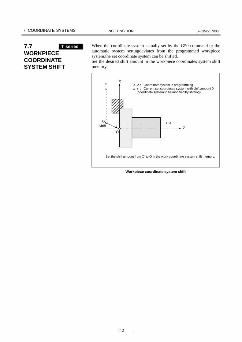
7. COORDINATE SYSTEMS B–63522EN/03NC FUNCTION
112
When the coordinate system actually set by the G50 command or theautomatic system settingdeviates from the programmed workpiecesystem,the set coordinate system can be shifted.Set the desired shift amount in the workpiece coordinates system shiftmemory.
ÅÅÅÅÅÅÅÅÅÅÅÅ
Z
X
z
x X–Z : Coordinate system in programmingx–z : Current set coordinate system with shift amount 0
(coordinate system to be modified by shifting)
O
O′
Set the shift amount from O′ to O in the work coordinate system shift memory.
Shift
Workpiece coordinate system shift
7.7WORKPIECE COORDINATE SYSTEM SHIFT(T series)
T series
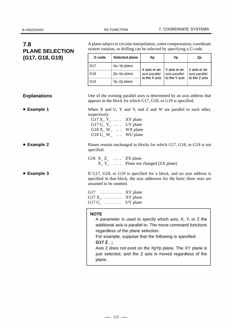
B–63522EN/03 7. COORDINATE SYSTEMSNC FUNCTION
113
A plane subject to circular interpolation, cutter compensation, coordinatesystem rotation, or drilling can be selected by specifying a G code.
G code Selected plane Xp Yp Zp
G17 Xp–Yp planeX axis or an Y axis or an Z axis or an
G18 Zp–Xp planeX axis or anaxis parallelto the X axis
Y axis or anaxis parallelto the Y axis
Z axis or anaxis parallelto the Z axis
G19 Yp–Zp planeto the X axis to the Y axis to the Z axis
One of the existing parallel axes is determined by an axis address thatappears in the block for which G17, G18, or G19 is specified.
When X and U, Y and V, and Z and W are parallel to each other,respectively
G17 X_ Y_ XY plane. . . . G17 U_ Y_ UY plane. . . . G18 X_ W_ WX plane. . . G18 U_ W_ WU plane. . .
Planes remain unchanged in blocks for which G17, G18, or G19 is notspecified.
G18 X_ Z_ ZX plane. . . . X_ Y_ Plane not changed (ZX plane). . . .
If G17, G18, or G19 is specified for a block, and no axis address isspecified in that block, the axis addresses for the basic three axes areassumed to be omitted.
G17 XY plane. . . . . . . . . . G17 X_ XY plane. . . . . . . . G17 U_ UY plane. . . . . . . .
NOTEA parameter is used to specify which axis, X, Y, or Z theadditional axis is parallel to. The move command functionsregardless of the plane selection.For example, suppose that the following is specified:G17 Z_ ;Axis Z does not exist on the XpYp plane. The XY plane isjust selected, and the Z axis is moved regardless of theplane.
7.8PLANE SELECTION (G17, G18, G19)
Explanations
� Example 1
� Example 2
� Example 3

8. COORDINATE VALUE AND DIMENSION B–63522EN/03NC FUNCTION
114
8 COORDINATE VALUE AND DIMENSION
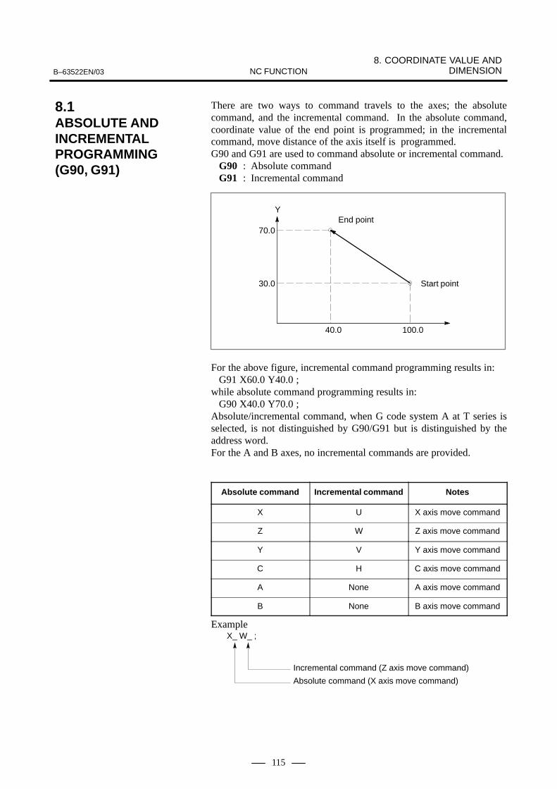
8. COORDINATE VALUE AND DIMENSIONB–63522EN/03 NC FUNCTION
115
There are two ways to command travels to the axes; the absolutecommand, and the incremental command. In the absolute command,coordinate value of the end point is programmed; in the incrementalcommand, move distance of the axis itself is programmed. G90 and G91 are used to command absolute or incremental command.
G90 : Absolute command G91 : Incremental command
100.040.0
30.0
70.0
YEnd point
Start point
For the above figure, incremental command programming results in: G91 X60.0 Y40.0 ;
while absolute command programming results in:G90 X40.0 Y70.0 ;
Absolute/incremental command, when G code system A at T series isselected, is not distinguished by G90/G91 but is distinguished by theaddress word. For the A and B axes, no incremental commands are provided.
Absolute command Incremental command Notes
X U X axis move command
Z W Z axis move command
Y V Y axis move command
C H C axis move command
A None A axis move command
B None B axis move command
ExampleX_ W_ ;
Incremental command (Z axis move command)
Absolute command (X axis move command)
8.1ABSOLUTE AND INCREMENTALPROGRAMMING(G90, G91)

8. COORDINATE VALUE AND DIMENSION B–63522EN/03NC FUNCTION
116
The end point coordinate value can be input in polar coordinates (radiusand angle). Use G15, G16 for polar coordinates command.
G15 : Polar coordinate system command cancel G16 : Polar coordinate system command
Plane selection of the polar coordinates is done same as plane selectionin circular interpolation, using G17, G18, G19. Command radius in the first axis of the selected plane, and angle in thesecond axis. For example, when the X-Y plane is selected, commandradius with address X, and angle with address Y. The plus direction of theangle is counter clockwise direction of the selected plane first axis +direction, and the minus direction the clockwise direction.Both radius and angle can be commanded in either absolute orincremental command (G90, G91).The center of the polar coordinates is the zero point of the workpiececoordinates. (However, if the local coordinates are set, it is the zero pointof the local coordinates.)
�Bolt hole cycle N1 G17 G90 G16;
Polar coordinates command, X-Y plane N2 G81 X100. Y30. Z-20. R-5. F200.;
100mm radius, 30� angle N3 X100. Y150;
100mm radius, 150� angleN4 X100. Y270;
100mm radius, 270� angleN5 G15 G80;
Polar coordinates cancel
Y
270° X
Workpiece coordinate system
150°30°
100mm
8.2POLAR COORDINATECOMMAND (G15, G16)(M series)
M series
Examples

8. COORDINATE VALUE AND DIMENSIONB–63522EN/03 NC FUNCTION
117
Conversion of inch and metric input can be commanded by the G codecommand.
G20 : Inch inputG21 : Metric input
Whether the output is in inch system or metric system is parameter-setwhen the machine is installed.Command G20, G21 at the head of the program.Inch/metric conversation can also be done by MDI setting. The contents of setting data differs depending on whether G20 or G21 iscommanded.
Numerals can be input with decimal points. Decimal points can be usedbasically in numerals with units of distance, speed, and angle. Theposition of the decimal point is at the mm, inch, deg position. There are two types of decimal point notation: calculator–type notationand standard notation.When calculator–type decimal notation is used, a value without decimalpoint is considered to be specified in millimeters, inch or deg. Whenstandard decimal notation is used, such a value is considered to bespecified in least input increments.Use parameters to select input method; whether to input by pocketcalculator type input, or by the usual decimal point input. Values can be specified both with and without decimal point in a singleprogram.
Program commandPocket calculator type
decimal point programming
Usual decimal pointprogramming
X1000Command value withoutdecimal point
1000mmUnit : mm
1mmUnit : Least input incre-ment (0.001 mm)
X1000.0Command value withdecimal point
1000mmUnit : mm
1000mmUnit : mm
Since the work cross section is usually circular in latches, its dimensionscan be specified in two ways when performing a thing:
When the diameter is specified, it is called diameter programming, andwhen the radius is specified, it is called radius programming. The diameter programming or radius programming can be selected byparameter for each axis.
A
B
D1 D2R1
R2
X axis
Z axis
D1, D2 Diameter programming
R1, R2 Radius programming
8.3INCH/METRICCONVERSION (G20, G21)
8.4DECIMAL POINT INPUT/POCKETCALCULATOR TYPE DECIMAL POINT INPUT
8.5DIAMETER AND RADIUSPROGRAMMING(T series)
T series

8. COORDINATE VALUE AND DIMENSION B–63522EN/03NC FUNCTION
118
A linear axis refers to an axis moving linearly, and for it values arespecified in mm or inches.A rotation axis refers to a rotating axis, and for it values are specified indegrees.For rotation axes, note the following:
� Inch-metric switching is not performed.
� The machine coordinate system is always normalized to the rangefrom 0deg to 360deg.
The rotation axis roll-over function rounds the absolute coordinate valueand relative coordinate value of a rotation axis to a coordinate valuewithin one rotation. This prevents coordinate values to overflow.In an incremental command, the specified value is regarded as the amountof travel.In an absolute command, the specified value is rounded to within onerotation. The resulting coordinate value is used as the end point. Aparameter is used to specify whether to determine the move direction bythe sign of the specified value or by the move distance (the shortest movedistance to the end point is selected).
When an absolute command is specified for a rotary axis for which therollover function is set, the tool moves in the direction indicated by thesign of the specified value, and the coordinates of the end point becomethe specified absolute values.
8.6LINEAR AXIS AND ROTATION AXIS
8.7ROTATION AXIS ROLL-OVERFUNCTION
8.8ROTARY AXIS CONTROL

B–63522EN/03 9. SPINDLE FUNCTIONSNC FUNCTION
119
9 SPINDLE FUNCTIONS

9. SPINDLE FUNCTIONS B–63522EN/03NC FUNCTION
120
Specify the spindle speed with up to five digits immediately after addressS. The 5-digit numeric value is output to the PMC as a 32-bit binary code.The code is maintained until another S is specified. The maximumnumber of input digits for S can be specified using a parameter.
The speed of the analog interface spindle is controlled. Specify the spindlespeed with up to five digits immediately after address S. According to thespecified spindle speed, a speed command is output to the spindle motorin a form of analog voltage. During constant surface speed control, ananalog voltage is output so that it matches the spindle speed reached afterconstant surface speed control.
The speed of the serial interface spindle is controlled.Specify the spindle speed with up to five digits immediately after addressS. A speed command is output to the spindle motor according to thespecified spindle speed. During constant surface speed control, a speedcommand is output so that it matches the spindle speed reached afterconstant surface speed control.
If a speed command for the spindle motor is input in a form of [sign +12-bit binary code], the command is output to the spindle motor accordingto the input.
9.1S CODE OUTPUT
9.2SPINDLE SPEED ANALOG OUTPUT (S ANALOG OUTPUT)
9.3SPINDLE SPEED SERIAL OUTPUT (S SERIAL OUTPUT)
9.4SPINDLE OUTPUT CONTROL BY THE PMC

B–63522EN/03 9. SPINDLE FUNCTIONSNC FUNCTION
121
Whether to perform constant surface speed control is specified using G96or G97.
G96 : Constant surface speed control modeG97 : Constant surface speed control cancel mode
If the surface speed is specified with an S code (S followed by a numericvalue) in the constant surface speed control mode, the spindle speed iscontrolled so that a constant surface speed can be maintained while thetool position is changing. The axis on which the calculation for constant surface speed control isbased can be specified with either a parameter or the following command:
G96 Pα ; P0 : Axis specified with a parameterPα : αth axis (α = 1 to 8)
The specifiable range of the S code is as follows:1 to 99999 m/min or feet/min
In the constant surface speed control cancel mode, the spindle speed isspecified using an S code.In the constant surface speed control mode, a constant surface speedcontrol on signal is output.By specifying the following command, the maximum spindle speed canbe set:
G50 S_ ; (with the G code system A in T series)or
G92 S_ ; (where, S-- is the maximum spindle speed in min–1)The spindle speed is clamped when it reaches the specified maximumspindle speed.
Generally, a machine that does not have (or which does not use) a positioncoder cannot perform feed per rotation under constant surface speedcontrol. When a certain parameter is set, such a machine can perform feedper rotation under constant surface speed control, assuming that S 12–bitcode signals R01O to R12O represent a specified spindle speed.(Constant surface speed control without a position coder: T series only)
To the spindle speed specified by S, an override from 0% to 254% can beapplied (in steps of 1%).
Actual spindle speed calculated by the return pulses of the position coderon the spindle is output in 16-bit binary code.
9.5CONSTANT SURFACESPEED CONTROL
9.6SPINDLE OVERRIDE
9.7ACTUAL SPINDLE SPEED OUTPUT (T series)
T series
9. SPINDLE FUNCTIONS B–63522EN/03NC FUNCTION
122
In turning operation, the spindle connected to the spindle motor rotatesat a certain speed, and the workpiece attached to the spindle is then turned.The spindle positioning function moves the spindle connected to thespindle motor by a given angle so that the workpiece attached to thespindle is positioned at a desired angle.With this function, any portion of the workpiece can be drilled. The spindle position is detected by the position corder attached to thespindle.Whether to use the spindle for spindle positioning (spindle positioningmode) or to use the spindle for spindle rotation (spindle rotation mode)is command by special M code (set by parameters).
� Move commandWhen commanded: G00 C_ ;, The spindle is positioned to the commanded position by rapidtraverse. Absolute (G90) and incremental (G91) command, as wellas decimal point input is possible.
� Increment systemLeast input increment: 0.001 deg.Detection unit: (360×N)/4096 deg.
N: Combination ratio of position coder and spindle (N=1, 2, 4)
9.8SPINDLEPOSITIONING (T series)
T series

B–63522EN/03 9. SPINDLE FUNCTIONSNC FUNCTION
123
This function monitor spindle speed, detects a higher level of fluctuationthan the commanded speed and signals an abnormality, if any, to themachine side, using an alarm, thereby preventing the spindle fromseizure, for example. Whether the spindle speed fluctuation detection isdone or not is specified by G code.
G25 : Spindle speed fluctuation detection is off.G26 : Spindle speed fluctuation detection is on.
G26 P_ Q_ R_ ;
P_ : Time from the change of spindle speed to the start of the spindle speed fluctuation detection (Unit: msec)
Q_ : The ratio of spindle speed to the specified spindle speed where spindle speed fluctuation detection starts (Units: %)
R_ : Fluctuation ratio regarded as an alarm (Unit: %)
NOTE1 The value of P, Q, and R remains after the power off.2 The actual spindle speed is calculated by the return pulses
generated from the position coder attached to the spindle.
There are two ways in generating an alarm:An alarm is generated before the specified spindle speed reaches. An alarm is generated after the specified spindle speed reaches.
9.9SPINDLE SPEED FLUCTUATIONDETECTION (G25, G26)
Format
Explanations

9. SPINDLE FUNCTIONS B–63522EN/03NC FUNCTION
124
CHECK CHECKNO CHECK
r
r
q
q d
d
Commanded speed : (Speed commanded by S) x (Spindle override)
Actual speed : Speed detected by position coder
q : (Allowable rate for starting checkup) x (Commanded speed)
r : (Fluctuation rate in which an alarm is given) x (Commanded speed)
d : Fluctuation width in which an alarm is given Cutting by parameter
Specifydifferentspeed
Checkstart
Alarm
Time
Actualspeed
Specifiedspeed
Spindlespeed
CHECK CHECKNO CHECK
r
r
qq d
d
Specifydifferentspeed
Checkstart
AlarmTime
Actualspeed
Specifiedspeed
Spindlespeed
p : Time between changes in commanded speed and check start.
� When an alarm isgenerated after thespindle speed becomesthe commanded speed.
� When an alarm isgenerated before thespindle speed becomesthe commanded speed.
B–63522EN/03 9. SPINDLE FUNCTIONSNC FUNCTION
125
The serial interface spindle permits positioning and linear interpolationwith another servo axis. Thus, linear interpolation between the spindleand a servo axis can be specified.
The serial interface spindle has two modes.
� The spindle rotation control mode controls the speed of the spindle.(The spindle is rotated according to a speed command.)
� The spindle contour control mode (also called Cs contour control)controls the position of the spindle. (The spindle is rotated accordingto a move command.)
These modes are switched by a signal sent from the PMC.
The axis subject to spindle contour control is placed as one of the CNCcontrol axes. Any of the control axes can be selected as the spindle contourcontrol axis.
In manual and automatic operation, a move command for the spindlecontour control axis is programmed in the same way as for a servo axis.
Example) Let the name of the spindle contour control axis be C.G00 C30.0 ; (Positioning)G01 X100.0 Y100.0 C90.0 F1000.0 ; (Linear interpolation)
� Switching from spindle rotation control to spindle contour controlIf there is a difference in servo loop gain between the axis subject tospindle contour control and the other servo axes, linear interpolationwith the spindle contour control axis cannot be performed properly.As soon as spindle rotation control is switched to spindle contourcontrol, an appropriate spindle contour control servo loop gain for aselected gear is automatically set for a necessary servo axis. The axisfor which the servo loop gain is to be changed, and the spindle contourcontrol servo loop gain for this axis must be set in parameters for eachgear beforehand.
� Switching from spindle contour control to spindle rotation controlAs soon as spindle contour control is switched to spindle rotationcontrol, the original servo loop gain is set for the servo axisautomatically.
9.10Cs CONTOUR CONTROL
Explanations
� Control mode
� Spindle contour controlaxis
� Move command
� Automatic loop gainsetting when switchingbetween spindle rotationcontrol and spindlecontour control is made

9. SPINDLE FUNCTIONS B–63522EN/03NC FUNCTION
126
Up to four spindles can be controlled. The three spindles are called thefirst, second, third, and fourth spindles. The first and second spindles aremade up of serial interface spindles, and the third spindle is of an analoginterface spindle. (The second or third spindle may be omitted from theconfiguration.)If no analog interface spindle is used, all the first to fourth spindles areconfigured with serial interface spindles.A spindle speed is specified with a 5-digit numeric value following S.This command functions on the spindle selected by spindle selectionsignals (SWS1 to SWS4). More than one spindle can be selected so thatthey can be rotated at the same time by specifying the same command.Each spindle holds a specified command (spindle speed). When thespindle is not selected by the spindle selection signal, the spindle rotatesat the held spindle speed. By using this feature, the spindles can be rotatedat different speeds at the same time. For each spindle, a signal to stopspindle rotation is provided (*SSTP1 to *SSTP4). With these signals,unnecessary spindles can be placed in the stopped state.Feedback pulses from the position coders connected to the first andsecond spindles can be input to the CNC to perform threading and feedper rotation. One of the position coders connected to the first and secondspindles is selected by a signal. The feedback pulse from the selectedcoder is then input to the CNC. From the third spindle, no feedback pulsecan be input.The multi–spindle control functions of the M and T series differ asfollows:
� For the M series, multi–spindle control is possible only when spindlegear selection type T is specified.
� For the M series, rigid tapping spindle selection signals (RGTSP1,RGTSP2, and RGTSP3) cannot be used.
� When two–path control is performed with the M series, spindlecommands and position coder feedback signals cannot be changedbetween the paths (spindle command select signals SLSPA andSLSPB, and spindle feedback select signals SLPCA and SLPCB arenot supported).
SWS1
SWS2
SWS3
*SSTP1
*SSTP2
*SSTP3
S command
Hold1stspindle
Positioncoder
Hold
Hold
2ndspindle
3rdspindle
Positioncoder
SWS4 *SSTP4Hold
4thspindle
9.11MULTI–SPINDLECONTROL

B–63522EN/03 9. SPINDLE FUNCTIONSNC FUNCTION
127
In machine tools having two spindles (such as a lathe), the speeds of thetwo spindles sometimes have to match. This requires when a workpieceheld on the first spindle is transferred to the second spindle while thespindles are rotating, and when acceleration/deceleration is performedwhile a workpiece is being held by the first and second spindles.When a workpiece having a different figure is transferred between thespindles, the rotation phases (rotation angles) of the spindles must alsomatch.The serial interface spindle synchronization control function is providedto provide synchronization control for two spindles.
You can perform spindle orientation simply by mounting a position coderon the spindle. Stoppers or pins for physically stopping the spindle at aspecified position are not necessary. A spindle can be instantly oriented,even when rotating at high speed, thereby greatly reducing the orientationtime.
Spindle output switching switches between the two windings, one for lowspeed and the other for high speed, incorporated into the special spindlemotors. This ensures that the spindle motor demonstrates stable outputcharacteristics over a wide range.
When one–path control or two CPUs with two–path control is performed,up to four serial spindles can be connected.The third serial spindle operates as an ordinary third analog spindle. Forthe third, as well as the first and second serial spindles, all the functionssupported by the serial spindle control unit (spindle orientation, spindleoutput switching, and spindle switching) can be used.When the third spindle orientation function is used, stop–positionexternal–setting type orientation can also be performed for the thirdspindle.When the fourth spindle orientation function is used, stop–positionexternal–setting type orientation can also be performed for the fourthspindle.
In simple spindle synchronous control mode, the second spindle can becontrolled as a slave axis of the first spindle.Thus, control based on the Cs contour axis control function, rigid tappingfunction, and spindle positioning function (T series) can be exercised overthe second spindle, under the control of the first spindle.Note, however, that unlike spindle synchronous control, simple spindlesynchronous control does not guarantee synchronization between the firstand second spindles.To realize simple spindle synchronous control, two serial spindlesystems, both of which support two–spindle connection, are required.Moreover, both spindles must be fitted with the spindle–related hardware,such as detectors, required for the functions used with simple spindlesynchronous control (Cs contour axis control function, rigid tappingfunction, and spindle positioning function (T series)).
9.12SPINDLESYNCHRONIZATIONCONTROL
9.13SPINDLEORIENTATION
9.14SPINDLE OUTPUT SWITCHING
9.15THREE/FOUR–SPINDLE SERIALOUTPUT
9.16SIMPLE SPINDLE SYNCHRONOUS CONTROL

9. SPINDLE FUNCTIONS B–63522EN/03NC FUNCTION
128
The advanced feedforward control function can be made usable for serialinterface spindles. This makes rigid tapping, Cs contour axis control (forthe first axis only), and spindle positioning (T series) usable even in theadvanced control mode.Because the fine acceleration/deceleration (FAD) function cannot beapplied to the serial interface spindle, however, it cannot be used for theservo axis if advanced control is applied to the serial interface spindle.
Appropriate parameter setting causes the current position coder position(the number of pluses) to be displayed with a precision of 4096 perrotation on the diagnosis screen.This data can be used to determine the current position of the spindle.
9.17SERIAL SPINDLE ADVANCEDCONTROL
9.18SPINDLE POSITION DATA DISPLAY

B–63522EN/03 10. TOOL FUNCTIONSNC FUNCTION
129
10 TOOL FUNCTIONS

10. TOOL FUNCTIONS B–63522EN/03NC FUNCTION
130
A tool can be selected by specifying a tool number of up to eight digitsimmediately after address T. The tool number is output to the PMC in a32-bit binary code. This code is kept till the next T code is commanded.Maximum input digits are set by parameters.
A tool and offset can be selected by specifying a tool number and offsetnumber of up to eight digits (in total) immediately after address T. Theoffset number is specified with the last one or two digits of the T code.The tool number is specified with the remaining digits after excluding theone or two digits used to specify the offset number.
T ��������
T ��������
When the last two digits are used to specify the offset number:
Offset number
Tool number
When the last one digit is used to specify the offset number:
Offset number
Tool number
The tool number is output in a 32-bit binary code. This code is kept tillthe next T code is commanded. Maximum input digits are set byparameters.
10.1T CODE OUTPUT
M series
T series
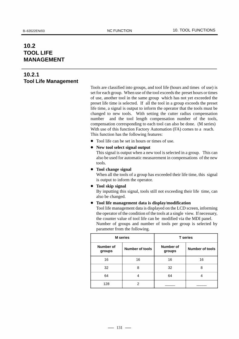
B–63522EN/03 10. TOOL FUNCTIONSNC FUNCTION
131
Tools are classified into groups, and tool life (hours and times of use) isset for each group. When use of the tool exceeds the preset hours or timesof use, another tool in the same group which has not yet exceeded thepreset life time is selected. If all the tool in a group exceeds the presetlife time, a signal is output to inform the operator that the tools must bechanged to new tools. With setting the cutter radius compensationnumber and the tool length compensation number of the tools,compensation corresponding to each tool can also be done. (M series)With use of this function Factory Automation (FA) comes to a reach.This function has the following features:
� Tool life can be set in hours or times of use.
� New tool select signal output This signal is output when a new tool is selected in a group. This canalso be used for automatic measurement in compensations of the newtools.
� Tool change signalWhen all the tools of a group has exceeded their life time, this signalis output to inform the operator.
� Tool skip signalBy inputting this signal, tools still not exceeding their life time, canalso be changed.
� Tool life management data is display/modificationTool life management data is displayed on the LCD screen, informingthe operator of the condition of the tools at a single view. If necessary,the counter value of tool life can be modified via the MDI panel.Number of groups and number of tools per group is selected byparameter from the following.
M series T series
Number ofgroups Number of tools Number of
groups Number of tools
16 16 16 16
32 8 32 8
64 4 64 4
128 2 _____ _____
10.2TOOL LIFE MANAGEMENT
10.2.1Tool Life Management

10. TOOL FUNCTIONS B–63522EN/03NC FUNCTION
132
The number of groups that can be registered in the tool life managementfunction and the allowable number of tools per group can be selected fromthe following four combinations. One of the combinations is selectedusing a parameter.
M series T series
Number ofgroups Number of tools Number of
groups Number of tools
64 16 16 32
128 8 32 16
256 4 64 8
512 2 128 4
The following features are added to the tool life management function foreasier handling:
� Setting tool life management data for each tool group by programAddition, modification, and deletion can be made to only the tool lifemanagement data of a specified group; the tool life management dataof the other groups is left intact.A tool life is set for each tool group by time or use count.
� Displaying and editing tool life management dataAll tool life management data is displayed on the screen, and so theuser can understand the current tool state instantly. The following dataitems are displayed:� Tool group number of the tool currently used� Tool group number selected next
Life, life counter value
List of tool numbers in the group
Cutter compensation number and toollength compensation corresponding toeach tool number
Use state for each tool (for example, indicating whether tool life is reached)
� Tool lifemanagement data
Tool life management data can be modified at the MDI panel. Inaddition, tool numbers can be added, changed, and deleted.
� Life count overrideIf a tool life is set by time, actual time obtained by multiplying the usetime of a tool by a magnification (override value) can be added to thelife counter. An override value from 0 to 99.9 is specified in steps of0.1 by a signal sent from the PMC.
Example)If the override value is 0.1, and the use time of a tool is ten minutes,the life counter is incremented by one minute.
10.2.2Addition of Tool Pairsfor Tool Life Management <512 Pairs (M series) / 128 Pairs (T series)>
M series10.2.3Extended Tool LifeManagement (M series)

B–63522EN/03 10. TOOL FUNCTIONSNC FUNCTION
133
� Tool life notice signalWhen the rest of the tool life (remainder value) until a new tool isselected is set as a value common to all groups, a signal is output tothe PMC when the value obtained by the subtraction (the life value(LIFE) minus the counter value (COUNT)) has reached the setremainder value.
With tool life management B, the features of the conventional tool lifemanagement function have been expanded as follows:
� Expanded life valueIn the conventional tool life management function, the maximum lifecount and time were 65535 times and 4300 minutes, respectively.When the tool life management B option is used, the maximum lifecount and time can be extended to 999999 and 100000 minutes,respectively.
� Support of setting of arbitrary tool group numbersIn the conventional tool life management function, the T code tospecify a target group for tool life management was the tool lifemanagement ignore number plus group number. In tool lifemanagement B, use of the function for setting arbitrary tool groupnumbers (bit 5 of parameter No. 6802) allows an arbitrary T code tobe used to specify a group.
� Tool life notice signal expansionIn the conventional tool life management function, the tool life noticesignal was able to be used to set the rest of the tool life until theselection of a new tool only as a value common to all groups. Withtool life management B, this value can be set for each group.
10.3TOOL LIFE MANAGEMENT B (MSERIES)
M series

11. MISCELLANEOUS FUNCTIONS B–63522EN/03NC FUNCTION
134
11 MISCELLANEOUS FUNCTIONS

B–63522EN/03 11. MISCELLANEOUS FUNCTIONSNC FUNCTION
135
When up to eight digits immediately after address M are specified, a32–bit binary code is output. The maximum number of input digits canbe specified with a parameter. This binary code is used for on/off controlof the machine. A block can usually contain up to three M codes althoughonly one of them is effective.The following M codes are used for special purposes:
M00 : Program stopM01 : Optional stop M02 : End of programM30 : End of program and tape rewind
The above M codes can also be output in binary codes. M98 (sub program call) and M99 (return from sub program) and alwaysprocessed in the CNC so, signal will not be output.
Up to three M codes can be simultaneously specified in one block. As these M codes are simultaneously sent to PMC side, the machiningcycle time compared with the conventional 1-block single M commandis reduced.
Example)(i) 1-block single M command
M40;M50;M60;G28G91X0Y0Z0; :
(ii) 1-block plural M commandM40M50M60;G28G91X0Y0Z0; :
NOTE1 The maximum input value of the first M code is 99999999,
while the maximum input values of the second and third Mcodes are 65535.
2 A strobe signal is provided for each of the first to third Mcodes (MF, MF2, and MF3). When all the operations for the first to third M codes arecompleted, completion signal FIN is output.
When an 8-digit number after address B is commanded, a 32-bit binarycode is output to the PMC. This code is kept till the next B code iscommanded.
11.1MISCELLANEOUSFUNCTIONS
11.21–BLOCK PLURAL M COMMAND
11.3SECONDMISCELLANEOUSFUNCTIONS

11. MISCELLANEOUS FUNCTIONS B–63522EN/03NC FUNCTION
136
The communication of execution command signal (strobe signal) andcompletion signal is the M/S/T/B function were simplified to realize ahigh-speed execution of M/S/T/B function. The time required for cutting can be minimized by speeding up theexecution time of M/S/T/B function. The following describes an example of auxiliary function M codecommand. The same applies to the T, S, and B (second auxiliary function)functions.When an M code is specified, the CNC inverts the logical level of strobesignal MF. Thus, when the signal is 0, it becomes 1. When it is 1, itbecomes 0. After inverting strobe signal MF, the CNC assumes thecompletion of PMC operation once the logical level of completion signalMFIN from PMC has become the same as the logical level of strobe signalMF.In the usual system, if the leading edge (from “0” to “1”) of the completionsignal FIN of M/S/T/B is received and then the trailing edge (from “1” to“0”) of the signal FIN is received, it is considered that the operation hasbeen completed. However, in this system, the operation is considered tohave been completed by a single change of completion signal MFIN.
Example) M10;M20;
M10 M20M command Mxx
code signal
Strobe signal MF
Operation at PMC side
M function completionsignal MFIN
High-speed System Time Chart
M10 M20M command Mxx
code signal
Strobe signal MF
Operation at RMC side
Completion signal FIN
Conventional System Time Chart
11.4HIGH-SPEED M/S/T/BINTERFACE

B–63522EN/03 11. MISCELLANEOUS FUNCTIONSNC FUNCTION
137
NOTE1 Either the conventional system or the high-speed system
can be selected for communication of strobe signal andcompletion signal.
2 In the conventional system, only one completion signal isavailable for all functions of M/S/T/B. However, in the high-speed system, one completion signal is available for eachof M/S/T/B functions.
The M code group check function checks if a combination of multiple Mcodes (up to three M codes) contained in a block is correct.This function has two purpose. One is to detect if any of the multiple Mcodes specified in a block include an M code that must be specified alone.The other purpose is to detect if any of the multiple M codes specified ina block include M codes that belong to the same group.
11.5M CODE GROUP CHECK FUNCTION

12. PROGRAM CONFIGURATION B–63522EN/03NC FUNCTION
138
12 PROGRAM CONFIGURATION

B–63522EN/03 12. PROGRAM CONFIGURATIONNC FUNCTION
139
A program number is given to each program to distinguish a programfrom other programs. The program number is given at the head of eachprogram, with a 4-digit number (when the 8–digit program number optionis used, however, eight digits following address O ) after the address O.Program number of the program currently under execution is alwaysdisplayed on the LCD screen. Even during the execution of a subprogram, the program number of the main program can also be displayedby parameter setting. Program search of programs registered in thememory is done with the program number. The program number can beused in various ways.
A program name can be given to the program to distinguish the programfrom other programs when displaying all the registered program on ascreen. Register the name between the control-out and the control-in.Any codes usable in the CNC can be used for the program name.The program name is displayed with the program number in the directorydisplay of registered programs. Note that the program name displayed iswithin 31 characters.
Example) 01234 (PROGRAM FOR ATC);
A program is divided into the main program and the sub program. TheCNC normally operates according to the main program, but when acommand calling a sub program is encountered in the main program,control is passed to the sub program. When a command indicating toreturn to the main program is encountered in the sub program, control isreturned to the main program.
12.1PROGRAM NUMBER
12.2PROGRAM NAME
12.3MAIN PROGRAM

12. PROGRAM CONFIGURATION B–63522EN/03NC FUNCTION
140
When there are fixed sequences or frequently repeated patterns in aprogram, programming can be simplified by entering these pattern as subprograms to the memory. Sub program is called by M98, and M99commands return from the sub program. The sub program can be nested4 folds.A sequence number in a sub program can also be specified for subprogram call.
O0001 ;
M98P1000 ;
M30 ;
O3000 ;
M99 ;
O1000 ;
M98P2000 ;
M99 ;
O2000 ;
M98P3000 ;
M99 ;
O4000 ;
M99 ;
M98P4000 ;
M99 ;
1-loop nesting
Main program Sub program Sub program Sub program Sub program
2-loop nesting 3-loop nesting 4-loop nesting
Sequence number
M98 P ��� ���� Q ����� ;
M99 ;
Sub program call
Return from sub program
If the number of repetitive calls is omitted, 1 is assumed.
When Q and a sequence number are omitted, the beginning ofthe sub program is called.
Number of repetitivecalls
Subprogram number
12.4SUB PROGRAM
Format

B–63522EN/03 12. PROGRAM CONFIGURATIONNC FUNCTION
141
When memory is used, a program cataloged in the floppy cassette ormemory card can be called and executed as a sub program.A sub program is called from the floppy cassette or memory card whenthe program using the memory executes the following block.
M198 P ��� ���� ;
Sub program calling
If the number of repetitive calls is omitted, 1 is assumed.
Number of repetitivecalls
Subprogram number or file number
NOTE1 Whether address P specifies the file number or program
number is selected by a parameter.2 In the program called by M198, no more sub program can
be called by M198.
Sequence number can be given in a 5-digit number after the address N atthe head of the program block. The sequence number of the program under execution is always displayedon the screen. The sequence number can also be searched in the programby the sequence number search function.
Either the EIA or the ISO code can be used as tape code. The inputprogram code is distinguished with the first end of block code (EIA: CR,ISO: LF). See the List of Tape Codes for tape codes used.
12.5EXTERNAL MEMORY AND SUB PROGRAM CALLING FUNCTION
Format
12.6SEQUENCE NUMBER
12.7TAPE CODES

12. PROGRAM CONFIGURATION B–63522EN/03NC FUNCTION
142
The following table shows the basic addresses and the range of values tobe specified. The range, however, is that of CNC. Note that the range ofthe machine is different from this.
Function Address Metric input Inch input
Program number O (Note1)1–99991–99999999 (Note3)
1–99991–99999999 (Note3)
Sequence number N 1–99999 1–99999
Preparatory function G 0–999 0–999
Dimensionword, Setting
IS–B X, Y, Z, Q,R, I, J, K,A, B, C, U,
±99999.999mm±99999.999deg
±9999.9999inch (Note2)±99999.999deg
word, Settingunit IS–C
R, I, J, K,A, B, C, U,
V, W±99999.9999mm±99999.9999deg
±999.99999inch (Note2)±9999.9999deg
Feed per minute,
IS–BF
1–240000mm/min 0.01–9600.00inch/minminute, Setting unit IS–C
F1–100000mm/min 0.01–4000.00inch/min
Feed per rotation,Setting unit F 0.01–500.00mm/rev 0.0001–9.9999inch/rev
Spindle function S 0–20000 0–20000
Tool function T 0–99999999 0–99999999
Miscellaneous func-tion
M 0–99999999 0–99999999Miscellaneous func-tion B 0–99999999 0–99999999
Dwell, Settingunit
IS–B
X, P
0–99999.999 (sec or rev)
0–99999.999 (sec or rev)
Dwell, Settingunit
IS–C
X, P0–9999.9999 (sec or rev)
0–9999.9999 (sec or rev)
Program numberspecification P 1–9999 1–9999
Number of repeats P 1–999 1–999
Offset number H, D 0–400 0–400
12.8BASIC ADDRESSES AND COMMAND VALUE RANGE
� Basic Addresses andRange of Values to BeSpecified (M series)

B–63522EN/03 12. PROGRAM CONFIGURATIONNC FUNCTION
143
Function Address Metric input Inch input
Program number O (Note1)1–99991–99999999 (Note3)
1–99991–99999999 (Note3)
Sequence number N 1–99999 1–99999
Preparatory function G 0–999 0–999
Dimensionword, Setting
IS–BX, Y, Z, U,V, W, A, B,
±99999.999mm±9999.9999deg
±9999.9999inch (Note2)±99999.999deg
word, Settingunit IS–C
V, W, A, B,C, I, J, K, R ±99999.999mm
±9999.9999deg±999.99999inch (Note2)±9999.9999deg
Feed per minute,
IS–BF
1–240000mm/min 0.01–9600.00inch/minminute, Setting unit IS–C
F1–100000mm/min 0.01–4000.00inch/min
Feed per rotation,Screw lead F
0.0001–500.000mm/rev
0.000001–9.999999inch/rev
Spindle function S 0–20000 0–20000
Tool function T 0–99999999 0–99999999
Miscellaneous function
M 0–99999999 0–99999999Miscellaneous function B 0–99999999 0–99999999
Dwell, Settingunit
IS–B
P, X, U
0–99999.999 (sec or rev)
0–99999.999 (sec or rev)
Dwell, Settingunit
IS–C
P, X, U0–9999.9999 (sec or rev)
0–9999.9999 (sec or rev)
Program numberspecification P 1–9999 1–9999
Number of repeats P 1–999 1–999
Sequence numberspecification P, Q 1–99999 1–99999
NOTE1 “:” can be used for 0 in ISO Code.2 Coordinates maximum command value for inch input/metric
output is limited to: ±3937.0078 inch (IS–B)/ ±393.70078inch (IS–C).
3 The 8–digit program number option is required.
� Basic Addresses andRange of Values to BeSpecified (T series)

12. PROGRAM CONFIGURATION B–63522EN/03NC FUNCTION
144
The variable block word address format with decimal point is adopted astape format. See List of Tape Format in Appendix C for details on tapeformats.
Label skip function is valid in the following cases, and “LSK” isdisplayed on the screen.�When power is put on. �When the NC is reset.
When label skip function is in valid, all codes to the first encountered endof block (EOB) code are ignored.The ignored part is called ”Reader part”, and section after the first end ofblock (EOB) code, “significant information”.
Information between the control-in and the control-out are regarded asnotes and are ignored.The reset codes (ISO code: %, EIA code: ER) cannot be used in this part.The ignored part is called “Notes”.
ISO code EIA code
Control–out ( Channel 2–4–5 on
Control–in ) Channel 2–4–7 on
When a slash and number ( /n) is programmed at the head of a program,and when the machine is operated with the optional block skip switch non the machine operator’s panel on, information in the block commandedwith the /n corresponding to the switch number n is ignored.If the optional block skip switch n is turned off, information in the /ncommanded block will not be ignored. The block with /n commanded canbe skipped by the operator’s selection. I can be used for n. The 1 to /1 can be omitted.
Example) /1 N12345 G00 X100.Z200.;
2 to 9 can also be used for the n of the /n.
A parity check is made on the number of punch holes for each input tapecharacter. If the parity does not match, an alarm occurs (TH check). Aparity check is made on each input data block. If the number of charactersin one block (from the code next to EOB to another EOB) is odd, an alarmoccurs (TV check). The TH or TV check cannot be made on the areaskipped by the label skip function. The TH check is not made on thecommand field.A parameter can be used to specify whether the charactersconstituting comments are to be counted when obtaining the number ofcharacters for TV check. The TV check function is validated orinvalidated according to the value set on the MDI panel.
12.9TAPE FORMAT
12.10LABEL SKIP
12.11CONTROL-IN/CONTROL-OUT
12.12OPTIONAL BLOCK SKIP
12.13ADDITIONALOPTIONAL BLOCK SKIP
12.14TAPE HORIZONTAL (TH) PARITY CHECK AND TAPE VERTICAL(TV) PARITY CHECK

13. FUNCTIONS TO SIMPLIFY PROGRAMMINGB–63522EN/03 NC FUNCTION
145
13 FUNCTIONS TO SIMPLIFY PROGRAMMING

13. FUNCTIONS TO SIMPLIFY PROGRAMMING B–63522EN/03NC FUNCTION
146
Canned cycle is a function to simplify commands for machining (boring,drilling, or tapping, etc. The canned cycle has the positioning plane andthe drilling axis. The positioning plane is specified with the planeselection of G17, G18, and G19. The drilling axis is the basic axis X, Yor Z (that does not compose the positioning plane) or its parallel axis.
G code Positioning plane Drilling axis
G17 Xp–Yp plane Xp
G18 Zp–Xp plane Yp
G19 Yp–Zp plane Zp
Xp : X axis or its parallel axis
Yp : Y axis or its parallel axis
Zp : Z axis or its parallel axis
The drilling axis address commanded in the same block as the G codes,G73 - G89, decides whether the drilling axis is the basic axis or its parallelaxis. If the drilling axis address was not commanded, the basic axisbecomes the drilling axis.Axis other than the drilling axis becomes the positioning axis.
Example) When U, V, W axes are set as parallel axes for X, Y, Z axes respectively.
G17G81 Z_ ; Drilling axis is Z axis.. . . . G17G81 W_; Drilling axis is W axis.. . . . G18G81 Y_ ; Drilling axis is Y axis.. . . . G18G81 V_ ; Drilling axis is V axis.. . . . G19G81 X_ ; Drilling axis is X axis.. . . . G19G81 U_ ; Drilling axis is U axis.. . . .
It is not always necessary to command G17, G18, G19 in the sameblock as G73 - G89.
NOTEZ axis can always be appointed the drilling axis byparameter setting.
Positioning can be commanded with optional axes other than the drillingaxis. The drilling cycle starts after the positioning.The following explanations are done on the XY plane, and Z axis as thedrilling axis. The following 13 types of canned cycles are available.
13.1CANNED CYCLES(G73, G74, G76, G80-G89, G98, G99)(M series)
M series

13. FUNCTIONS TO SIMPLIFY PROGRAMMINGB–63522EN/03 NC FUNCTION
147
R point
Initial level
Z point
q
d
R point
SpindleCCW
Spindle CW
PR point
SpindleCCW
Spindle CW
R point level
SpindleCW Initial
level
Spindle CW
OSS
G codeOperation
G98 mode G99 modeFunction
G73 High–speedpeck drillingcycle
(Note 1)
13 types of canned cycles (1/4)
G74Counter tapping cycle
G76 FIne boringcycle
R pointR pointlevel
q
q
q
q
q
d
d
d
Z point
Initial level
P
Z pointZ pointP
P
R point R point R pointlevel
Z point Position Zq
q
PP
OSS

13. FUNCTIONS TO SIMPLIFY PROGRAMMING B–63522EN/03NC FUNCTION
148
G codeOperation
G98 mode G99 modeFunction
G81Drilling cycle(Spot drilling)
G83 Small holepock drillingcycle
Positon R
G82Drilling cycle(Counter boring)
�����
Over–load torque
�����
G83 Peck drillingcycle
(Note 1)
13 types of canned cycles (2/4)
Initial level
R point
q
d
Z point
R pointR pointlevel
Z point Z point
Initial level
Initial level
R point R pointR pointlevel
Z point Z pointP P
Initial level
R point R pointR pointlevel
dd
d d
q
q
q
q
q
qZ point Z point
R point
q
d
d
d
d
d
Z point
Over–load torque

13. FUNCTIONS TO SIMPLIFY PROGRAMMINGB–63522EN/03 NC FUNCTION
149
G codeG98 mode G99 mode
G84Tapping cycle
G87 Back boringcycle
G85Boring cycle
G86 Boring cycle
Initial level
Spindle stop
OSS
P
OperationFunction
13 types of canned cycles (3/4)
Initial level
Initial level
Positon R Positon R
Spindle CWSpindle CW
PP
R pointlevel
Z point Z pointP P
Spindle CCW Spindle CCW
Positon R Positon RR pointlevel
Z point Z point
Spindle CW
Spindle CW
Positon R Positon R R pointlevel
Z point Z point
Spindle stop
Not usedSpindle CW
Spindle CW
Z point
R point
qOSS

13. FUNCTIONS TO SIMPLIFY PROGRAMMING B–63522EN/03NC FUNCTION
150
G codeG98 mode G99 mode
G89Boring cycle
G88 Boring cycle
DwellSpindle stop
Initial level
OperationFunction
13 types of canned cycles (4/4)
R pointlevel
P
Spindle CW
R point
Z point
Spindle CW
R point
Initial level
DwellSpindle stop
Z pointP
R point R pointlevel
Z point Z pointP P
Note 1 ”d” of G73 and G83 is set by parameters.
OSSCutting feed
Rapid traverse
Manual feed
Z Z point(Hole bottom position)
P Dwell
Oriented spindle stop (Spindle stops atconstant rotation position)
Shift
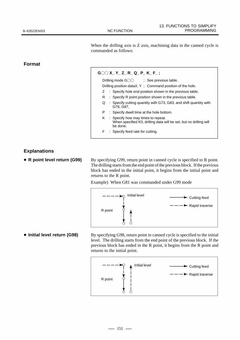
13. FUNCTIONS TO SIMPLIFY PROGRAMMINGB–63522EN/03 NC FUNCTION
151
When the drilling axis is Z axis, machining data in the canned cycle iscommanded as follows:
G�� X_ Y_ Z_ R_ Q_ P_ K_ F_ ;
Drilling mode G�� ; See previous table.
Drilling position dataX, Y ; Command position of the hole.
Z : Specify hole end position shown in the previous table.
R : Specify R point position shown in the previous table.
Q : Specify cutting quantity with G73, G83, and shift quantity with G76, G87,
P : Specify dwell time at the hole bottom.
K : Specify how may times to repeat. When specified K0, drilling data will be set, but no drilling will be done.
F : Specify feed rate for cutting.
By specifying G99, return point in canned cycle is specified to R point.The drilling starts from the end point of the previous block. If the previousblock has ended in the initial point, it begins from the initial point andreturns to the R point.
Example) When G81 was commanded under G99 mode
Initial level
R point
Cutting feed
Rapid traverse
By specifying G98, return point in canned cycle is specified to the initiallevel. The drilling starts from the end point of the previous block. If theprevious block has ended in the R point, it begins from the R point andreturns to the initial point.
Initial level
R point
Cutting feed
Rapid traverse
Format
Explanations
� R point level return (G99)
� Initial level return (G98)

13. FUNCTIONS TO SIMPLIFY PROGRAMMING B–63522EN/03NC FUNCTION
152
In tapping, the feed amount of drilling axis for one rotation of spindleshould be equal to the pitch of screw of tapper. Namely, the followingconditions must be satisfied in the best tapping:P= F/S, where P : Pitch of screw of tapper (mm)
F : Feed rate of drilling axis (mm/min) S : Spindle speed (rpm)
The rotation of spindle and feed of Z axis are independently controlled inthe tapping cycle G74/G84 (M series), G84/G88 (T series). Therefore, theabove conditions may not always be satisfied. Especially at the holebottom, both the rotation of spindle and feed of drilling axis reduce thespeed and stop. After that, they move in the inverse direction whileincreasing the speed. However, the above conditions may not be satisfiedin general since each acceleration/deceleration is performedindependently. Therefore, in general, the feed is compensated bymounting a spring to the inside of holder of tapper to improve the accuracyof tap cutting.The rotation of spindle and feed of drilling axis are controlled so that theyare always synchronous each other in the rigid tapping cycle. Namely, inother than rigid tapping, control for speed only is performed. In the rigidtapping however, position control is also performed during the rotationof spindle, that is, the rotation of spindle and feed of drilling axis arecontrolled as linear interpolation of two axes. This allows the following condition to be satisfied also duringacceleration/deceleration at the hole bottom and a tapping of improvedaccuracy to be made.
P = F/S The pitch of screw tap can be directly specified. Rigid tapping can be performed by executing any of the followingcommands:� M29 S����� before tapping command G74/G84 (M series)
or G84/G88 (T series)� M29 S����� in the same block as tapping command G74/G84
(M series) or G84/G88 (T series)� G74/G84 (M series) or G84/G88 (T series) as rigid tapping G code
(Whether G74/G84 (G84/G88) is used as rigid tapping G code or ordinary tapping G code can be selected with a parameter.)
13.2RIGID TAPPING
13.2.1Rigid Tapping

13. FUNCTIONS TO SIMPLIFY PROGRAMMINGB–63522EN/03 NC FUNCTION
153
Distributedpulse
Spindlemotor
Gear ration : m
SpindleGear ratio1 : p
Spindleamplifier
D/A converter
Positioncoder
Errorcounter
Spindle control (voltage calculation ofspindle speed rpm)
×4
DMR
×4
CMR
The Control System of Spindle during Rigid Tapping
Gear ratio of spindle toposition coder (1 : p)
Least command increment(detection unit ) deg
1 : 1 0.088 (1x360 / 4096)
1 : 2 0.176 (2x360 / 4096)
1 : 4 0.352 (4x360 / 4096)
1 : 8 0.703 (8x360 / 4096)
Even use of the spindle motor incorporating the position coder enablesrigid tapping. In this case, the gear ratio of the spindle motor and thespindle is set by the parameter. In addition, use of the spindle motor incorporating the position coderenables rigid tapping but disables threading and per revolution dwell.
Override with a previously set parameter value can be applied to thepull–out operation.Theoretically, it is possible to apply a pull–out override of up to 2000%(20 times). (Also take machine–imposed restrictions into account.)If an override result would exceed the maximum permissible spindlerotation speed (specified in a parameter) for rigid tapping, the actualspindle speed is clamped at the maximum permissible spindle rotationspeed.
Pull–out override
� Parameter setting–basedmethod

13. FUNCTIONS TO SIMPLIFY PROGRAMMING B–63522EN/03NC FUNCTION
154
A program instruction can specify to apply override to a pull–outoperation. (Using this method requires setting an additional parameter.)To specify pull–out override with a program instruction, specify apull–out spindle rotation speed as one of the hole making data items ina G84 block, using the J address.This instruction applies override with a value obtained in the followingexpression to a pull–out operation.
Spindle rotation speed (instruction with the J address) for a return
Spindle rotation speed (instruction with the S address)
�100 = Pull–out override value
If the result of conversion made with the above expression does not fallin a pull–out override range of from 100% to 2000%, the spindle rotationinstruction is disabled for the pull–out operation; the actual spindlerotation becomes 100%.If the J instruction value is greater than the maximum permissible spindlerotation speed (specified in a parameter) for rigid tapping, the actualspindle rotation speed is clamped at or near the maximum permissiblespindle rotation speed.
Example) To make a pull–out operation twice faster than a cut–in operation, usethe following instructions:�
M29 S1000;G84 Z–1000. F1000 J2000 ;�
Appropriate parameter setting enables the conventional feedrate overrideselect signal and override cancel signal even when rigid tapping is underway.In this case, the override value selected by the override select signal canbe used for rigid tapping.
� <G012#0–7> is used as the override select signal.
� <G006#4> is used as the override cancel signal.
� The override value can be changed even when rigid tapping is underway.
� Using an applicable option enables the second feedrate overridefunction. This function is applied to the second feedrate that isdetermined according to the first feedrate override function.
� The spindle override value is fixed at 100% when rigid tapping isunder way. Because the spindle operation is synchronized with theoperation of the tapping axis, the spindle speed is affected indirectlyby the feedrate override value.
� Enabling the feedrate override select signal disables pull–out override(regardless of whether it is specified by a program instruction or owingto a rigid tapping return), causing feedrate override to be applied to thepull–out operation.
� Programinstruction–basedmethod
Feedrate override

13. FUNCTIONS TO SIMPLIFY PROGRAMMINGB–63522EN/03 NC FUNCTION
155
� Even if the feedrate override select signal is enabled, setting theoverride cancel signal to 1 causes 100% override to be applied to acut–in operation. If pull–out override is enabled, it is applied to thepull–out operation.
The following table lists rigid tapping versus override valuecorrespondence.
Rigid tapping versus feedrate override value correspondence
Cut–in operation
Pull–out operation
Feedrate override = DisabledPull–out override = Disabled
���� ����
Feedrate override = DisabledPull–out override = Enabled
���� Pull–out override (*)
Feedrate override= EnabledPull–out override= Disabled
Override cancel signal����� ��
Feedrate override signalvalue
Feedrate override signalvalue
= DisabledOverride cancel signal����� �1
���� ����
Feedrate override= EnabledPull–out override= Enabled
Override cancel signal����� ��
Feedrate override signalvalue
Feedrate override signalvalue
= EnabledOverride cancel signal����� �1
���� Pull–out override (*)
* The pull–out override can be any of the following:<1> Parameter–set pull–out override<2> Program–specified pull–out override<3> Rigid tapping return–based pull–out override

13. FUNCTIONS TO SIMPLIFY PROGRAMMING B–63522EN/03NC FUNCTION
156
Bell–shaped acceleration/deceleration can be used for rigid tapping.Generally, using bell–shaped acceleration/deceleration can reduce therequired acceleration/deceleration time because the time constant of rigidtapping can be decreased.For bell–shaped acceleration/deceleration for rigid tapping, the linearacceleration/deceleration constant and the time corresponding to thebell–shaped curve are specified using parameters.The bell–shaped acceleration/deceleration time for rigid tapping is thesum of the time constant of linear acceleration/deceleration for the spindleand rigid tapping axis (conventional parameter setting T1) and the timecorresponding to the curved portion (parameter setting T2).
Maximum permissible spindle rotation speed
Time
Spindle rotation speed
T1T2
2
T2
2
T1 = Time constant of linear acceleration/deceleration forthe spindle and rigid tapping axis
T2 = Time constant for the curved portion of bell–shapedacceleration/deceleration
T1 + T2 = Time required for acceleration/deceleration
The actual time constant of liner acceleration/deceleration for the spindleand tapping axis, T1, is determined according to a ratio of the maximumpermissible spindle rotation speed to the actually specified S. However,the time constant for the curved portion of bell–shaped acceleration/deceleration is not proportional to the actual S instruction, so a constantacceleration/deceleration (specified using a parameter) is alwaysmaintained.
13.2.2Rigid TappingBell–shapedAcceleration/Deceleration (M series)
M series

13. FUNCTIONS TO SIMPLIFY PROGRAMMINGB–63522EN/03 NC FUNCTION
157
Issuing a rigid tapping instruction in the three–dimensional coordinateconversion mode can cause a rigid tapping operation to be performed atan angle specified in a three–dimensional coordinate conversioninstruction.Three–dimensional rigid tapping is used always together withthree–dimensional coordinate conversion.
The following functions related to rigid tapping are also available:
� Rigid tapping by manual handle feed (See Section II–23.10.)
� Rigid tapping return (See Section II–24.11.)
13.2.3Three–dimensionalRigid Tapping
13.2.4Other Rigid TappingFunctions (M series)
M series

13. FUNCTIONS TO SIMPLIFY PROGRAMMING B–63522EN/03NC FUNCTION
158
With the above program, external operation signal is output afterpositioning. G80 command cancels the external operation function.
G81 _ ;
: Optional combination of axis address X, Y, Z, U, V, W, A, B, C
IP
IP
13.3EXTERNALOPERATIONFUNCTION (G81)(M series)
M series
Format

13. FUNCTIONS TO SIMPLIFY PROGRAMMINGB–63522EN/03 NC FUNCTION
159
The following three kinds of canned cycle are provided.
The command below actuates a straight cutting cycle.
X/2
X axis
Z axis
2(F)3(F) 1(R)
4(R)Z W
U/2
R : Rapid traverse
F : Feed
G77 X_ Z_ F_ ;
The command below actuates a tapered cutting cycle.In the figure below, when the direction of route 1 is –X, R is a negativevalue. Inverting the sign of R enables reverse taper cutting.
X/2
X axis
Z axis
2(F)3(F) 1(R)
4(R)Z
W
U/2
R : Rapid traverse
F : Feed
R
G77 X_ Z_ R_ F_ ;
13.4CANNED CYCLES FOR TURNING (T series)
T series
13.4.1Cutting Cycle A (G77)(with G Code System A:G90)
� Straight cutting cycle.
Format
� Tapered cutting cycle
Format
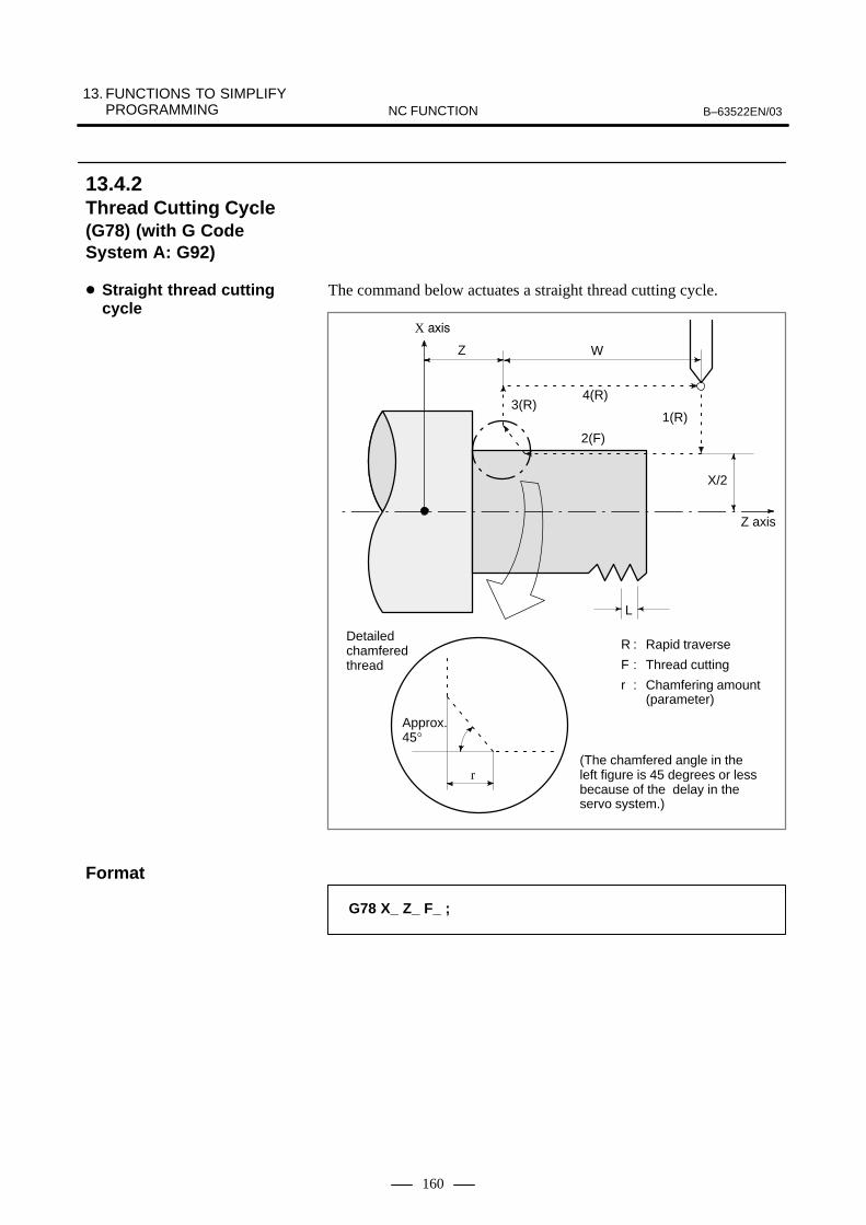
13. FUNCTIONS TO SIMPLIFY PROGRAMMING B–63522EN/03NC FUNCTION
160
The command below actuates a straight thread cutting cycle.
R : Rapid traverse
F : Thread cutting
r : Chamfering amount(parameter)
X/2
X ����
Z axis
Z
L
1(R)
2(F)
3(R)4(R)
r
W
Approx.45°
(The chamfered angle in theleft figure is 45 degrees or lessbecause of the delay in theservo system.)
Detailedchamferedthread
G78 X_ Z_ F_ ;
13.4.2Thread Cutting Cycle(G78) (with G CodeSystem A: G92)
� Straight thread cuttingcycle
Format

13. FUNCTIONS TO SIMPLIFY PROGRAMMINGB–63522EN/03 NC FUNCTION
161
The command below actuates a tapered thread cutting cycle.
2(F)
4(R)
X/2
1(R)3(R)
r
L
Z W
U/2
R
R : Rapid traverse
F : Thread cutting
r : Chamfering amount(parameter)
X ����
Z axis
Approx.45°
(The chamfered angle in theleft figure is 45 degrees or lessbecause of the delay in theservo system.)
Detailedchamferedthread
G78 X_ Z_ R_ F_ ;
NOTEScrew chamfering can be inhibited by entering thechamfering signal.
� Tapered thread cuttingcycle
Format

13. FUNCTIONS TO SIMPLIFY PROGRAMMING B–63522EN/03NC FUNCTION
162
The command below actuates a face cutting cycle.
X axis
0
4(R)
X/2
3(F)
Z axis
1(R)
2(F)U/2
Z
WX/2
U/2
Z
R : Rapid traverse
F : Feed
G79 X_ Z_ F_ ;
The command below actuates a face tapered cutting cycle.In the following figure, if the direction of the path 1 is negative in Z axis,the sign of the number following address R is negative.
X axis
4(R)
X/2
3(F)
Z axis
1(R)
2(F)U/2
Z
WR
R : Rapid traverse
F : Feed
G79 X_ Z_ R_ F_ ;
13.4.3Turning Cycle inFacing (G79) (with G Code System A:G94)
� Face cutting cycle
Format
� Face tapered cuttingcycle
Format

13. FUNCTIONS TO SIMPLIFY PROGRAMMINGB–63522EN/03 NC FUNCTION
163
A multiple repetitive cycle is composed of several canned cycles. A toolpath for rough machining, for example, is determined automatically bygiving the data of the finishing work shape. A thread cutting cycle hasalso been prepared.
There are two types of rough cutting cycles for external surfaces, type Iand type II.
If a finishing shape of A to A’ to B is given in the figure below, machiningis done with the cutting depth delta d and the finishing allowance deltaU/2 and delta W.
B
(F) (R)e
A
C
∆d
A’
45°
(R)
(F)
Programcommand
R : Rapid traverseF : Cutting feedd : Parameter setting
∆U/2
∆W
13.5MULTIPLEREPETITIVE CYCLESFOR TURNING (G70 - G76) (T series)
T series
13.5.1Stock Removal inTurning (G71)
� Type I
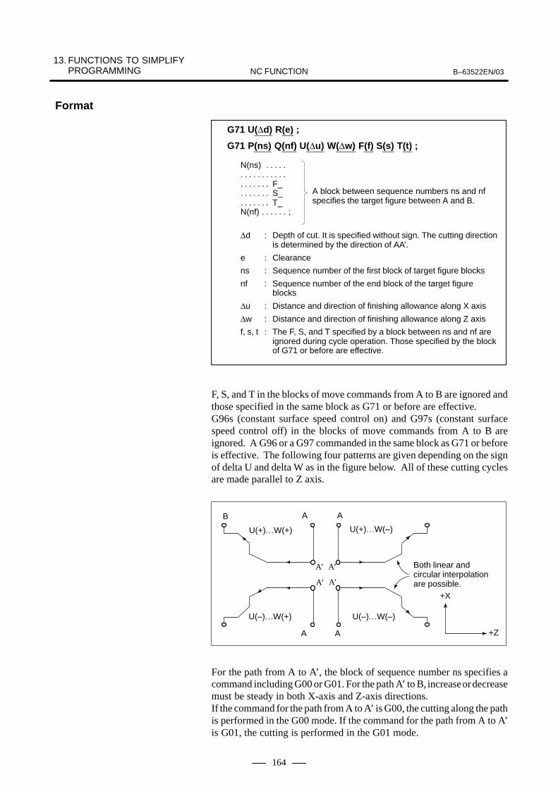
13. FUNCTIONS TO SIMPLIFY PROGRAMMING B–63522EN/03NC FUNCTION
164
G71 U(∆d) R(e) ;
G71 P(ns) Q(nf) U(∆u) W(∆w) F(f) S(s) T(t) ;
N(ns) . . . . . . . . . . . . . . . .
F_. . . . . . . S_. . . . . . . T_. . . . . . .
N(nf) ;. . . . . .
A block between sequence numbers ns and nfspecifies the target figure between A and B.
∆d : Depth of cut. It is specified without sign. The cutting directionis determined by the direction of AA’.
e : Clearance
ns : Sequence number of the first block of target figure blocks
nf : Sequence number of the end block of the target figure blocks
∆u : Distance and direction of finishing allowance along X axis
∆w : Distance and direction of finishing allowance along Z axis
f, s, t : The F, S, and T specified by a block between ns and nf are ignored during cycle operation. Those specified by the blockof G71 or before are effective.
F, S, and T in the blocks of move commands from A to B are ignored andthose specified in the same block as G71 or before are effective.G96s (constant surface speed control on) and G97s (constant surfacespeed control off) in the blocks of move commands from A to B areignored. A G96 or a G97 commanded in the same block as G71 or beforeis effective. The following four patterns are given depending on the signof delta U and delta W as in the figure below. All of these cutting cyclesare made parallel to Z axis.
B A
A’
A
A’
AA
A’A’
+X
+Z
U(+)…W(+)
Both linear and circular interpolationare possible.
U(–)…W(+) U(–)…W(–)
U(+)…W(–)
For the path from A to A’, the block of sequence number ns specifies acommand including G00 or G01. For the path A’ to B, increase or decreasemust be steady in both X-axis and Z-axis directions.If the command for the path from A to A’ is G00, the cutting along the pathis performed in the G00 mode. If the command for the path from A to A’is G01, the cutting is performed in the G01 mode.
Format

13. FUNCTIONS TO SIMPLIFY PROGRAMMINGB–63522EN/03 NC FUNCTION
165
Type II differs from Type I in the following point.Increase in X-axis direction does not need to be steady. Up to 10 pocketsare allowed.
12310 . . . . . . . . .
In Z-axis direction, however, increase or decrease must be steady. Thefollowing figure is not allowed for machining.
Change in Z-axis directionis not steady.
The first cutting does not need to be vertical. Any profile is allowed as faras the change in Z-axis direction is steady.For clearance after turning, chamfering is performed along the workpieceprofile.
e (setting by parameter)
The following figure shows an example of a cutting path when there aretwo pockets.
18
30
213
17
4
293 51
257
6
26
2728
248
914 10
15
202122
23
12
1611 19
� Type II

13. FUNCTIONS TO SIMPLIFY PROGRAMMING B–63522EN/03NC FUNCTION
166
The offset of tool tip R is not added to the finishing allowance ∆u and ∆w.It is assumed to be zero for cutting. Generally ∆w=0 is specified.Otherwise, the tool catches into a side wall. The two axes X(U) and Z(W)are specified in the first block of the repeat part. If there is no movementin Z-axis direction, W0 is specified.This function is effective only in memory mode.
Type I:Used when only one axis is specified in the first block (ns block) in therepeat part.
Type IIUsed when two axes are specified in the first block in the repeat part.
Example)Type I
G71 10.0 R5.0 ;G71 P100 Q200 … ;N100 X(U)_ ; :B200… ;
Type II
G71 10.0 R5.0 ;G71 P100 Q200 … ;N100 X(U)_ Z(W)_ ; :B200… ;
� Use of Types I and II

13. FUNCTIONS TO SIMPLIFY PROGRAMMINGB–63522EN/03 NC FUNCTION
167
As shown in the figure below, this cycle is the same as G71 except thatcutting is made parallel to X-axis.
A’
∆u/2
∆d
B
Tool path
(F)
(R)e
45°(R)
(F)
A
C
∆w
R : Rapid traverse
F : Feed
d : Parameter setting
Command
G72 W(∆d) R(e) ;
G72 P(ns) Q(nf) U(∆u) W(∆w) F(f) S(s) T(t) ;
∆d, e, ns, nf, ∆u, ∆w, f, s, and t are the same as those in G71.
For the shape to be cut by G72, the following four patterns are considered.Any of them is cut by repetition of operation parallel to the X axis of thetool. The signs of ∆U and ∆W are as follows:
BB
A A’
U(+)…W(–)…
AA
A A’
+X
+Z
U(+)…W(+)…
U(–)…W(–)…U(–)…W(+)…
Both linear and cir-cular interpolationare possible.It is possible eventhere are manypockets.
A’A’
B B
This function is effective only in memory mode.
13.5.2Stock Removal inFacing (G72)
Format

13. FUNCTIONS TO SIMPLIFY PROGRAMMING B–63522EN/03NC FUNCTION
168
This function permits cutting a fixed cutting pattern repeatedly with theposition being displaced bit by bit. By this cutting cycle, it is possible toefficiently cut the work whose rough shape has already been made byrough machining, forging, or casting, etc.
∆w
A’
∆u/2
B
(R)
A
D
∆k+∆w
C
∆w
∆u/2
R : Rapid traverseF : Cutting feed
Pattern to be specified by the programPoint A→ Point A’→ Point B
G73 U(∆i) W(∆k) R(d) ;
G73 P(ns) Q(nf) U(∆u) W(∆w) F(f) S(s) T(t) ;
N(ns) . . . . . . . . . . . . . . . .
F_. . . . . . . S_. . . . . . . T_. . . . . . .
N(nf) ;. . . . . .
The move commands for the target figure from Ato A’ then to B are specified by blocks betweensequence numbers ns and nf.
∆i : Distance and direction of the clearance along X axis (radius programming)
∆k : Distance and direction of the clearance along Z axis
d : Number of divisions which is equal to the number of times that rough cutting is performed
ns : Sequence number of the first block of target figure blocks
nf : Sequence number of the end block of target figure blocks
∆u : Distance and direction of the finishing allowance along X axis (diameter or radius programming)
∆w : Distance and direction of the finishing allowance along Z axis
f, s, t : F, S, and T codes
CAUTIONF, S, and T specified by any block between ns and nf areignored. Those specified by the block of G73 or before areeffective.
This function is available for only memory mode.
13.5.3Pattern Repeating(G73)
Format
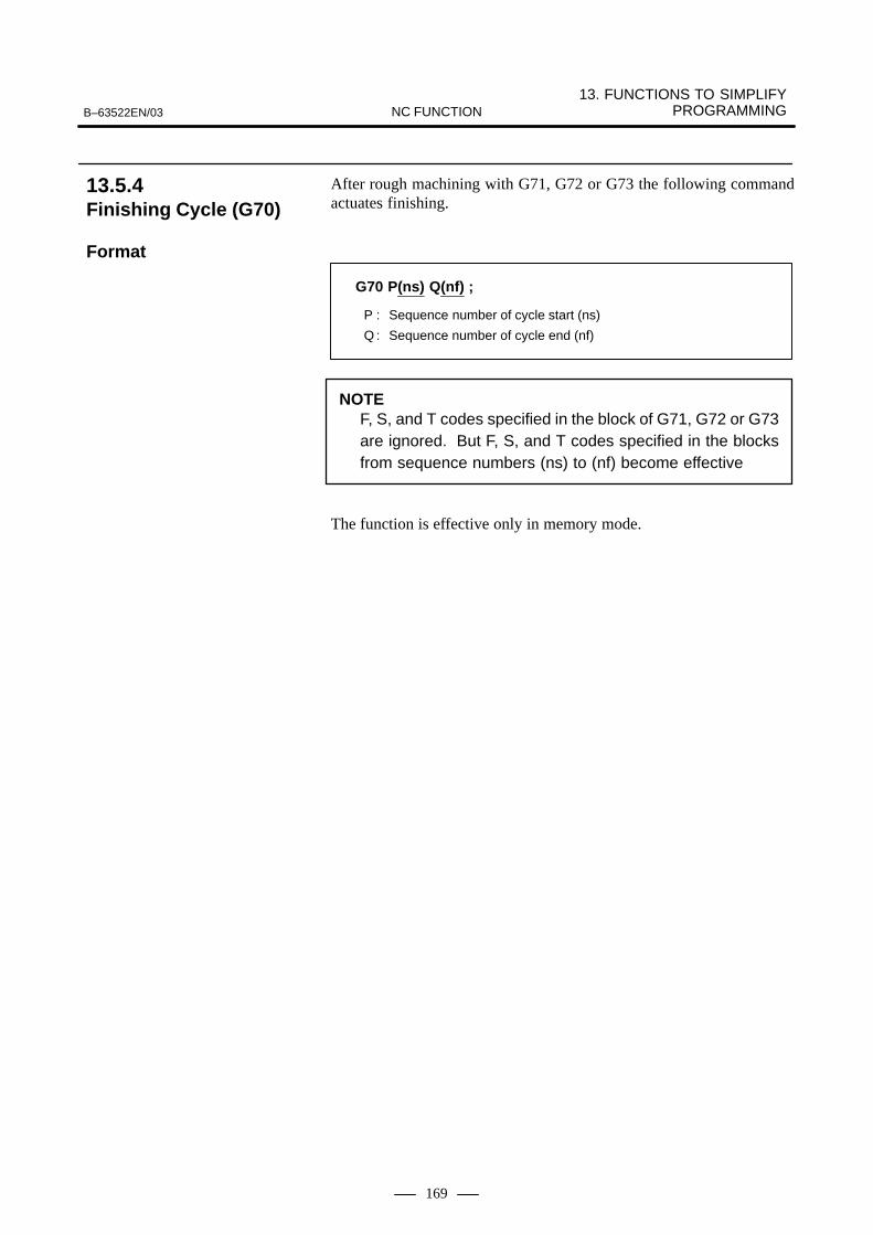
13. FUNCTIONS TO SIMPLIFY PROGRAMMINGB–63522EN/03 NC FUNCTION
169
After rough machining with G71, G72 or G73 the following commandactuates finishing.
G70 P(ns) Q(nf) ;
P : Sequence number of cycle start (ns)
Q : Sequence number of cycle end (nf)
NOTEF, S, and T codes specified in the block of G71, G72 or G73are ignored. But F, S, and T codes specified in the blocksfrom sequence numbers (ns) to (nf) become effective
The function is effective only in memory mode.
13.5.4Finishing Cycle (G70)
Format

13. FUNCTIONS TO SIMPLIFY PROGRAMMING B–63522EN/03NC FUNCTION
170
The following command permits operation as seen in the figure below.Chip breaking is possible in this cycle. Also if both x(u) and P areomitted, the machining is done only in the Z-axis resulting in peckdrilling.
U/2
W
∆d
C
∆k’
A
(R)
(F)
∆i
e
B X
(F)
[0<∆i’�∆i]
∆k ∆k ∆k ∆k
(R) (R) (R) (R)
(F) (F) (F)(F)
[0<∆k’�∆k]
∆i
∆i’
R � ����� ��������
F : Cutting feed
(X_, Z_)
G74 R(e) ;
G74 X_ Z_ P(∆i) Q(∆k) U(∆d) F(f) ;
e : Amount of return
X : X-axis coordinate of point B
U : Increment for A → B (for G code system A)
Z : Z-axis coordinate of point C
W : Increment for A → C (for G code system A)
∆i : Movement amount in X-axis direction (without sign)
∆k : Depth of cut in Z-axis direction (without sign)
∆d : Clearance amount at the cutting bottomUsually a positive integer is specified. If X(U) and ∆i are omitted, however, the sign indicating the direction is added.
f : Feedrate
X_ Z_U_W_
13.5.5Peck Drilling in Z-axis(G74)
Format

13. FUNCTIONS TO SIMPLIFY PROGRAMMINGB–63522EN/03 NC FUNCTION
171
The following tape command permits operation as seen in the figurebelow. This is equivalent to G74 except that X is replaced by Z. Chipbreaking is possible in this cycle. Grooving in the X-axis (in this case,Z, W and Q are omitted) is possible.
W
A
∆i
X
(R)
(R)
(R)
(R)
(R)
(F)
(F)
(F)
(F)
(F)
e
U/2
∆d∆k
R � ����� ��������
F : Cutting feed
(X_, Z_)
G75 R(e) ;
G75 X_ Z_ P(∆i) Q(∆k) R(∆d) F(f) ;X_ Z_U_W_
13.5.6Grooving in X-axis(G75)
Format

13. FUNCTIONS TO SIMPLIFY PROGRAMMING B–63522EN/03NC FUNCTION
172
A thread cutting cycle as shown below can be made.
W
C
(F)
(R) A
U/2
∆d
E
i
X
Z
r
D k
B
(R)
R � ����� ��������
F : Cutting feed
G76 P(m)(r)(a) Q(∆d min) R(d) ;
G76 X_ Z_ R(i) P(k) Q(∆d) F(�) ;
m : Number of final finishing repeats 1 to 99
r : Screw finishing (chamfering amount)
a : Tool tip angle (thread angle)One of the six angles, 80°, 60°, 55°, 30°, 29°, and 0°, can be selected as a 2-digit number. m, r, and a are specified inaddress P at the same time.
Example)When m = 2, r = 1.2�, and a = 60°, they are specified as follows:
∆bmin: Minimum depth of cut
d : Finishing allowance
i : Difference in thread radiusStraight threading for i = 0
k : Height of the thread (The distance in X-axis direction is specified with a radius value.)
∆d : Depth of first cut (specified with a radius value)
� : Screw lead (same as threading of G32)
X_ Z_U_W_
P02m
12r
60a
13.5.7Thread Cutting Cycle(G76)
Format

13. FUNCTIONS TO SIMPLIFY PROGRAMMINGB–63522EN/03 NC FUNCTION
173
ÔÔÔÔÔÔÔÔÔÔÔÔÔÔÔÔÔÔÔÔÔÔÔÔÔÔÔÔÔÔÔÔÔÔÔÔÔÔÔÔÔÔÔÔÔÔÔÔÔÔÔÔÔÔÔÔÔÔÔÔÔÔÔ
k
∆d
∆d�nFirst
SecondThird
nth
Tool tip
α
B
d
Cutting method in detail
NOTEThread chamfering can be inhibited by entering thechamfering signal.

13. FUNCTIONS TO SIMPLIFY PROGRAMMING B–63522EN/03NC FUNCTION
174
The canned cycles for drilling enable one block including the G functionto specify the machining which is usually specified by several blocks.Programming is then simplified.The canned cycles for drilling conform to JIS B 6314.
Canned cycles
G code Drillingaxis Drilling
Operationat holebottom
Clearance Use
G80 Cancel
G83 Z axisCutting feedIntermittentfeed
DwellRapid traverse
Deep drilling
G84 Z axis Cutting feedSpindle reverse
Cutting feed Tapping
G85 Z axis Cutting feed Dwell Cutting feed Boring
G87 X axisCutting feedIntermittentfeed
DwellRapid traverse
Deep drilling
G88 X axis Cutting feedSpindle reverse
Cutting feed Tapping
G89 X axis Cutting feed Dwell Cutting feed Boring
13.6CANNED CYCLES FOR DRILLING (G80 - G89) (T series)
T series
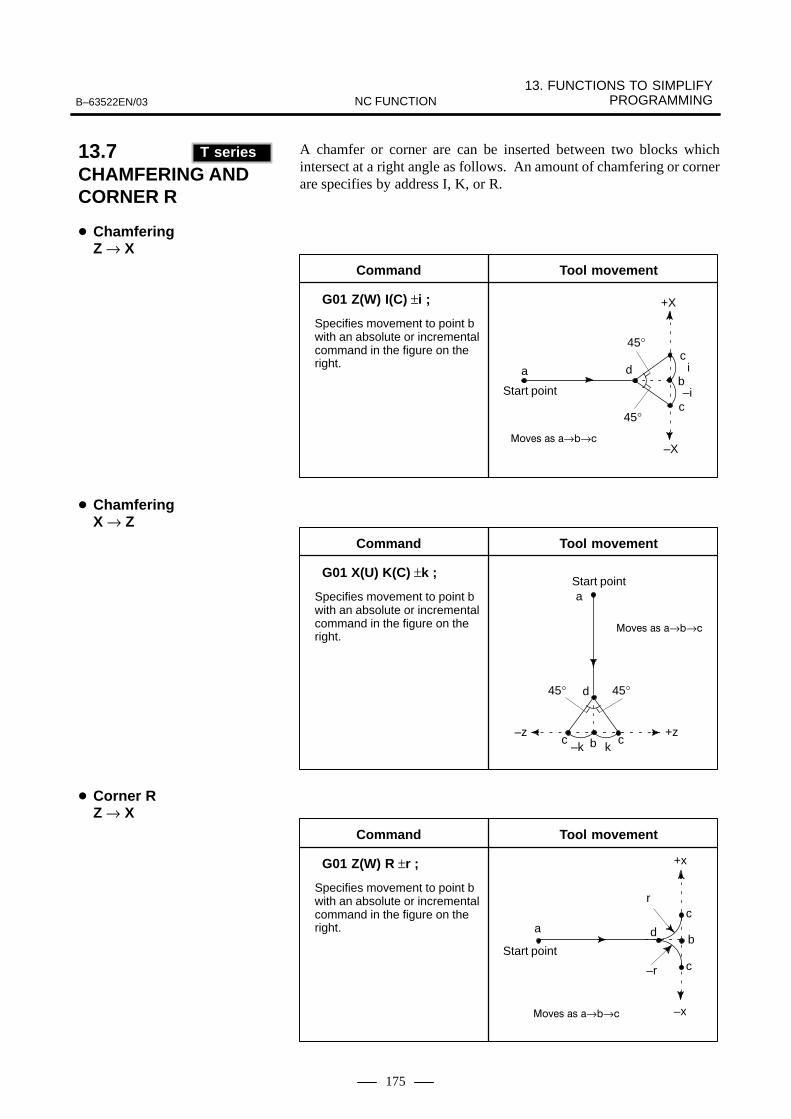
13. FUNCTIONS TO SIMPLIFY PROGRAMMINGB–63522EN/03 NC FUNCTION
175
A chamfer or corner are can be inserted between two blocks whichintersect at a right angle as follows. An amount of chamfering or cornerare specifies by address I, K, or R.
45°
+X
–X
ac
b–i
c
d
Start point
Command
G01 Z(W) I(C) ±i ;
Specifies movement to point bwith an absolute or incrementalcommand in the figure on theright. i
Tool movement
45°
����� �� �→�→�
a
Command
G01 X(U) K(C) ±k ;
Specifies movement to point bwith an absolute or incrementalcommand in the figure on theright.
Tool movement
Start point
45° 45°d
–z +zbc c
–k k
����� �� �→�→�
Command
G01 Z(W) R ±r ;
Specifies movement to point bwith an absolute or incrementalcommand in the figure on theright.
Tool movement
Start point
a
+x
–x
c
b
c
r
–r
d
����� �� �→�→�
13.7CHAMFERING AND CORNER R (T series)
T series
� ChamferingZ → X
� ChamferingX → Z
� Corner RZ → X

13. FUNCTIONS TO SIMPLIFY PROGRAMMING B–63522EN/03NC FUNCTION
176
Command
G01 X(U) R ±r ;
Specifies movement to point bwith an absolute or incrementalcommand in the figure on theright.
Tool movement
Start point a
–z +z
–r r
c cb
d
����� �� �→�→�
CAUTIONIf C is not used as an axis name, C can be used for a chamferaddress instead of I or K.
270.0
530.0
N3C3
R6
Z
X
N2
N1
N1 Z270.0 R60.0 ;N2 X860.0 K–3.0 ;N3 Z0 ;
� Corner RX → Z
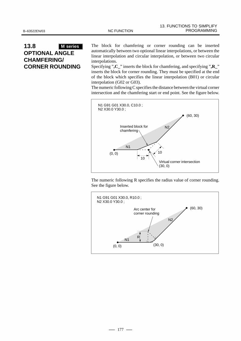
13. FUNCTIONS TO SIMPLIFY PROGRAMMINGB–63522EN/03 NC FUNCTION
177
The block for chamfering or corner rounding can be insertedautomatically between two optional linear interpolations, or between thelinear interpolation and circular interpolation, or between two circularinterpolations.Specifying ”,C_” inserts the block for chamfering, and specifying ”,R_”inserts the block for corner rounding. They must be specified at the endof the block which specifies the linear interpolation (B01) or circularinterpolation (G02 or G03).The numeric following C specifies the distance between the virtual cornerintersection and the chamfering start or end point. See the figure below.
Inserted block for chamfering
N1
N2
10
10(0, 0)
(60, 30)
Virtual corner intersection(30, 0)
N1 G91 G01 X30.0, C10.0 ;N2 X30.0 Y30.0 ;
The numeric following R specifies the radius value of corner rounding.See the figure below.
Arc center for corner rounding
N1 G91 G01 X30.0, R10.0 ;N2 X30.0 Y30.0 ;
N1
N2
(0, 0)
(60, 30)
(30, 0)
R
13.8OPTIONAL ANGLE CHAMFERING/CORNER ROUNDING(M series)
M series
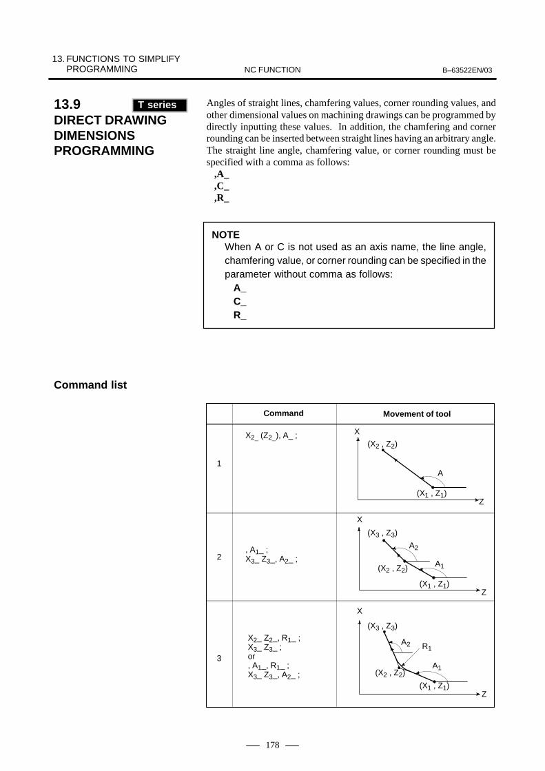
13. FUNCTIONS TO SIMPLIFY PROGRAMMING B–63522EN/03NC FUNCTION
178
Angles of straight lines, chamfering values, corner rounding values, andother dimensional values on machining drawings can be programmed bydirectly inputting these values. In addition, the chamfering and cornerrounding can be inserted between straight lines having an arbitrary angle.The straight line angle, chamfering value, or corner rounding must bespecified with a comma as follows:
,A_,C_,R_
NOTEWhen A or C is not used as an axis name, the line angle,chamfering value, or corner rounding can be specified in theparameter without comma as follows: A_ C_ R_
(X1 , Z1)
(X2 , Z2)
A
X
Z
Command
(X1 , Z1)
(X3 , Z3)
(X2 , Z2)
X
Z
A1
A2
(X1 , Z1)
(X3 , Z3)
(X2 , Z2)
X
Z
A1
A2 R1
X2_ (Z2_), A_ ;
, A1_ ;X3_ Z3_, A2_ ;
X2_ Z2_, R1_ ;X3_ Z3_ ;or, A1_, R1_ ;X3_ Z3_, A2_ ;
1
2
3
Movement of tool
13.9DIRECT DRAWING DIMENSIONSPROGRAMMING(T series)
T series
Command list

13. FUNCTIONS TO SIMPLIFY PROGRAMMINGB–63522EN/03 NC FUNCTION
179
R1
(X4 , Z4)
R2
C2
R2
(X1 , Z1)
(X3 , Z3)
(X2 , Z2)
X
Z
A1
A2
C1
X2_ Z2_, C1_ ;X3_ Z3_ ;or, A1_, C1_ ;X3_ Z3_, A2_ ;
Command Movement of tool
X2_ Z2_, R1_ ;X3_ Z3_, R2_ ;X4_ Z4_ ;or, A1_, R1_ ;X3_Z3_, A2_ R2_ ;X4_ Z4_ ;
X2_ Z2_, C1_ ;X3_ Z3_, C2_ ;X4_ Z4_ ;or, A1_, C1_ ;X3_ Z3_, A2_ C2_ ;X4_ Z4_ ;
X2_ Z2_, R1_ ;X3_ Z3_, C2_ ;X4_ Z4_ ;or, A1_, R1_ ;X3_ Z3_ , A2_ C2_ ;X4_ Z4_ ;
X2_ Z2_, C1_ ;X3_ Z3_, R2_ ;X4_ Z4_ ;or, A1_, C1_ ;X3_ Z3_, A2_ R2_ ;X4_ Z4_ ;
4
5
6
7
X
X
X
(X3 , Z3)
(X3 , Z3)
(X3 , Z3)
(X2 , Z2)
(X2 , Z2)
(X2 , Z2)
(X1 , Z1)
(X1 , Z1)
(X1 , Z1)
A2
A2
A2
A1
A1
A1
Z
Z
Z
(X4 , Z4)
(X4 , Z4)
C1
R1
C2
Z
X
(X4 , Z4)
(X3 , Z3)
(X2 , Z2)
(X1 , Z1)
A2
C1A1
8

13. FUNCTIONS TO SIMPLIFY PROGRAMMING B–63522EN/03NC FUNCTION
180
Mirror image can be commanded on each axis by programming. Ordinarymirror image (commanded by remote switch or setting) comes after theprogrammable mirror image is applied.
� Setting of programmable mirror imageG51.1 X_ Y_ Z_ ; is commanded and mirror image is commanded to each axis (as ifmirror was set on the axis).
� Programmable mirror image cancelG50.1 X_ Y_ Z_ ; is commanded and the programmable mirror image is canceled.
CAUTIONIf mirror image is specified only for one axis on the specifiedplane, the operation of the commands is as follows:� Arc command: The rotation direction is reversed.� Cutter compensation: The offset direction is reversed.� Coordinate rotation: The rotation angle is reversed.
When shape of the workpiece is symmetric to an axis, a program formachining the whole part can be prepared by programming a part of theworkpiece using programmable mirror image and sub program.
Main programN10 G00 G90 ;N20 M98 P9000 ;N30 G51.1 X50.0 ;N40 M98 P9000 ;N50 G51.1 Y50.0 ;N60 M98 P9000 ;N70 G50.1 X0 ;
(Cancel only X–axis)N80 M98 P9000 ;N90 G50.1 Y0 ;
Y
50
0 X
60
100(1)(2)
(3) (4)
Axis of symmetry (X=50)
Axis of symmetry (Y=50)
Sub programO9000 ; G00 G90 X60.0 Y60.0 ;G01 X100.0 F100 ;G01 Y100.0 ;G01 X60.0 Y60.0 ;M9950 60 100
13.10PROGRAMMABLEMIRROR IMAGE (G50.1, G51.1) (M series)
M series

13. FUNCTIONS TO SIMPLIFY PROGRAMMINGB–63522EN/03 NC FUNCTION
181
Mirror image can be applied to X axis with G code.G68 : Double turret mirror image on G69 : Mirror image cancel
When G68 is designated, the coordinate system is shifted to the matingturret symmetrical cutting.To use this function, set the distance between the two turrets at parameter.
X
60120
180
�
φ120
φ80φ40
�
120
Z
Offset amountof tool post A
Offset amountof tool post B
Tool post A
Tool post B
�
X40.0 Z180.0 T0101 ; Position turret A at �.G68 ; Shift the coordinate system by the distance A to B (120 mm),
and turn mirror image on. X80.0 Z120.0 T0202 ; Position turret B at �. G69 ; Shift the coordinate system by the distance B to A, and turn
mirror image on.X120.0 Z60.0 T101 ; Position turret A at �.
13.11MIRROR IMAGE FOR DOUBLE TURRETS (G68, G69) (T series)
T series

13. FUNCTIONS TO SIMPLIFY PROGRAMMING B–63522EN/03NC FUNCTION
182
The index table on the machining center is indexed by using the fourthaxis as an indexing axis. To command for indexing, an indexing angle is only to be specifiedfollowing a programmed axis (arbitrary 1 axis of A, B, C as the rotationaxis) assigned for indexing. It is not necessary to command the exclusiveM code in order to clamp or unclamp the table and therefore programmingwill become easy.
13.12INDEX TABLE INDEXING (M series)
M series

13. FUNCTIONS TO SIMPLIFY PROGRAMMINGB–63522EN/03 NC FUNCTION
183
The repetitive machining specific to grinding can be specified by oneblock. Since four types of canned cycles are provided for grinding,programming is simplified.
G71 G72
Skip signal
: Dwell : Dwell
G73 G74
Skip signal
: Dwell : Dwell
13.13CANNED CYCLES FOR CYLINDRICAL GRINDING (T series)
T series
Traverse grinding cycle(G71, G72)
Oscillating grindingcycle (73, G74)

13. FUNCTIONS TO SIMPLIFY PROGRAMMING B–63522EN/03NC FUNCTION
184
A : The first cutting depth
B : The second cutting depth
W : Grinding range
U : Dwell time Maximum command time 9999.999 sec.
I : Feed rate of A and B
K : Feed rate of W
H : Repetition frequency Setting value 1-9999
� (I)
� � (K)
� (I)
�
� (K)
A
BU (Dwell)
X
�
W
G71 A_ B_ W_ U_ I_ K_ H_ ;
U(Dwell)
P : Gauge number (1-4)
G72 P_ A_ B_ W_ U_ I_ K_ H_ ;
(Stopping)
Skip signal
(Stopping) Skip signal
If the option of the multi-step skip is employed, gauge number can bespecified. The specifying means of the gauge number is the same as themulti-step skip. If the option of the multi-step skip is not employed, aconventional skip signal becomes effective. Commands other than gaugenumber are similar to G71.
13.13.1Traverse GrindingCycle (G71)
13.13.2Traverse Direct GaugeGrinding Cycle (G72)

13. FUNCTIONS TO SIMPLIFY PROGRAMMINGB–63522EN/03 NC FUNCTION
185
A : Cutting depth
B : Cutting depth
W: Grinding range
U : Dwell time
K : Feed rate
H : Repetition frequency Setting value 1-9999
(B)
�� (K)
�
� (K)
X
Z
U (Dwell)A
W
G73 A_ B_ W_ U_ K_ H_ ;
U (Dwell)
P : Gauge number (1-4)
G74 P_ A_ (B_) W_ U_ K_ H_ ;
(Stopping)
Skip signal
Skip signal(Stopping)
If the option of the multi-step skip is employed, gauge number can bespecified. The specifying means of the gauge number is the same as themulti-step skip. If the option of the multi-step skip is not employed, aconvectional skip signal becomes effective. Commands other than gaugenumber are similar to G73.
13.13.3Oscillation GrindingCycle (G73)
13.13.4Oscillation DirectGauge Grinding Cycle(G74)

13. FUNCTIONS TO SIMPLIFY PROGRAMMING B–63522EN/03NC FUNCTION
186
In the surface grinding canned cycle, repeated cutting peculiar to grindingmachining normally commanded by a number of blocks, is simplyprogrammed by commanding one block which includes the G function.There are the following 4 types of grinding canned cycle. �Plunge grinding cycle G75 �Plunge direct grinding cycle G77�Continuous feed plane grinding cycle G78� Intermittent feed plane grinding cycle G79
13.14SURFACE GRINDING CANNED CYCLE (M series)
M series

13. FUNCTIONS TO SIMPLIFY PROGRAMMINGB–63522EN/03 NC FUNCTION
187
The plunge grinding cycle is possible by the following command.
G75 I_ J_ K_ X(Z)_ R_ F_ P_ L_ ;
I : The first cutting depth (Cutting direction is by command coding.)
J : The second cutting depth (Cutting direction is by command coding.)
K : Total cutting depth
X(Z) : Grinding range (Grinding direction is by command coding.)
R : Feed rate of I and J
F : Feed rate of X(Z)
P : Dwell time
L : Grindstone wear compensation number (Note 1)
Note 1) L is specified when performing continuous dressing.
Note 2) X(Z), I, J and K commands are all incremental commands.
� (R)I
J
X(Z)
� P
� (F)
� P
X(Z)
Y
� (F)
� (R)
The plunge grinding cycle is made up from the following sequence of 6operations.The operations from � up to � are repeated until the grindstone cuttingamount reaches the total cutting amount specified by address K.
� Grindstone cutting :Cuts in Y axis direction by cutting feed only the amount specified bythe first cutting depth 1. The feed rate becomes the rate specified byR.
� Dwell :Performs dwell for only the time specified by P.
� Grinding :Shift by cutting feed only the amount specified by X (or Z) in the Xaxis direction (or Z axis direction). The feed rate becomes the ratespecified by F.
13.14.1Plunge Grinding Cycle(G75)
Format
Explanations
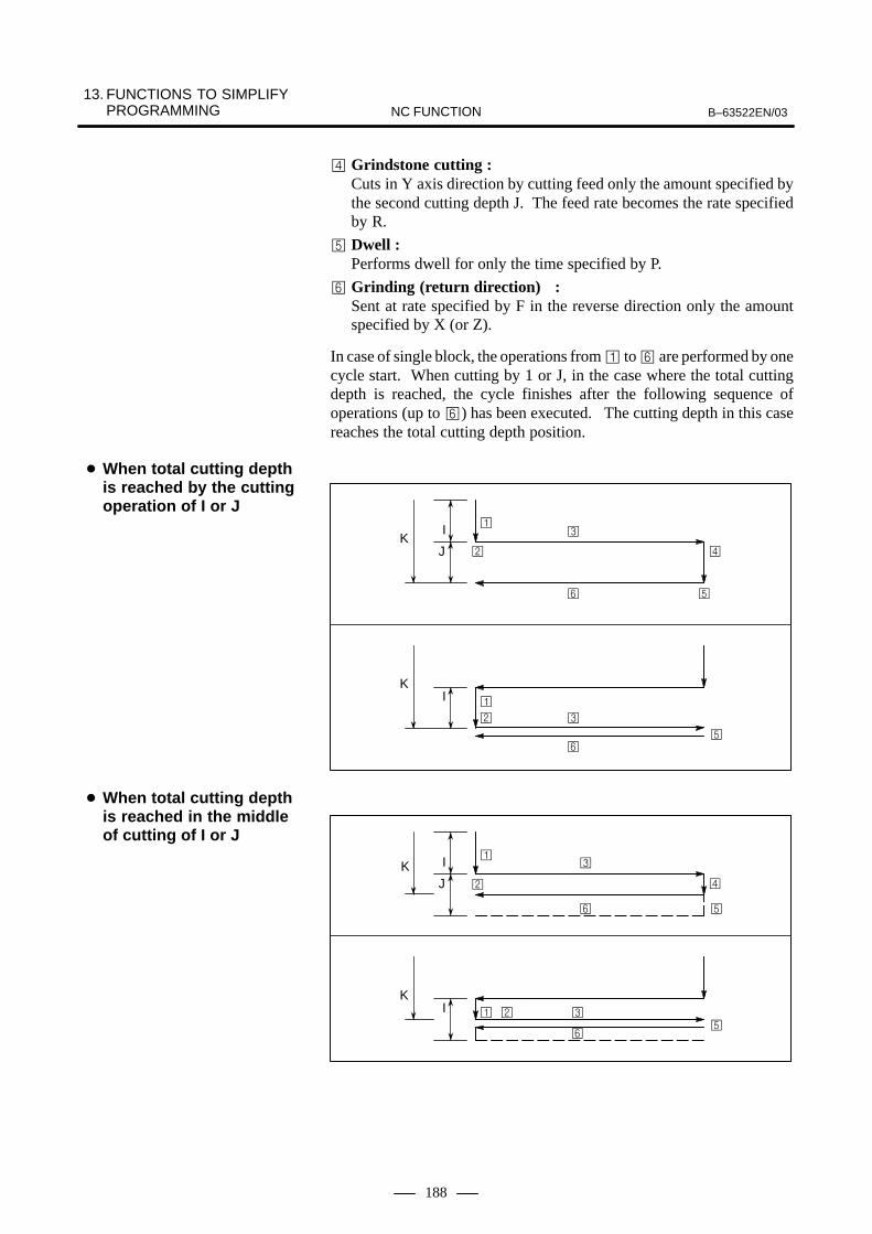
13. FUNCTIONS TO SIMPLIFY PROGRAMMING B–63522EN/03NC FUNCTION
188
� Grindstone cutting :Cuts in Y axis direction by cutting feed only the amount specified bythe second cutting depth J. The feed rate becomes the rate specifiedby R.
� Dwell :Performs dwell for only the time specified by P.
� Grinding (return direction) :Sent at rate specified by F in the reverse direction only the amountspecified by X (or Z).
In case of single block, the operations from � to � are performed by onecycle start. When cutting by 1 or J, in the case where the total cuttingdepth is reached, the cycle finishes after the following sequence ofoperations (up to �) has been executed. The cutting depth in this casereaches the total cutting depth position.
I
J �
�
�
��
K
IK
� �
��
�
�
I
JK
IK
�
�
�
��
� ��
�
�
�
� When total cutting depthis reached by the cuttingoperation of I or J
� When total cutting depthis reached in the middleof cutting of I or J

13. FUNCTIONS TO SIMPLIFY PROGRAMMINGB–63522EN/03 NC FUNCTION
189
The plunge direct grinding cycle is possible by the following command.
G77 I_ J_ K_ X(Z)_ R_ F_ P_ L_ ;
The command method is the same as the G75 case except for the G code.Further, even for the operation, the same sequence of 6 operations as theG75 case is repeated. G77 differs from G75 as follows: Inputting a skip signal during a cyclecan terminate the cycle after stopping (or terminating) the currentoperation sequence.The following shows the operation at skip signal input for each operationsequence.
Cutting immediately stops and returns to X(Z) coordinate at cycle start.
Skip signal
Skip signal
(Stopping)(Stopping)
(Stopping)
Skip signal
Dwell immediately stops and returns to X(Z) coordinate at cycle start.
After shift of X(Z) has finished, returns to X(Z) coordinate at cycle start.
(Stopping)
Skip signal
(Stopping)
Skip signal
13.14.2Plunge Direct GrindingCycle (G77)
Format
Explanations
� Case of during operationsequence � and �(when I and J shift)
� Case of during operationsequence � and �(during dwell)
� Case of during operationsequence � and �(when X(Z) shifts)

13. FUNCTIONS TO SIMPLIFY PROGRAMMING B–63522EN/03NC FUNCTION
190
The continuous feed plane grinding cycle is possible by the followingcommand.
G78 I_ (J)_ K_ X_ R_ F_ P_ L_ ;
I : Cutting depth (Cutting direction is by command coding.)
J : Cutting depth (Cutting direction is by command coding.)
K : Total cutting depth
X : Grinding range (Grinding direction is by command coding.)
F : Feed rate
P : Dwell time
L : Grindstone wear compensation number (Note 1)
Note 1) L is specified when performing continuous dressing.
Note 2) X, I, J and K commands are all incremental commands.
I
I(J)
X
� P(Dwell)� (F)
� P(Dwell)� (F)
X
Z
The continuous feed plane grinding cycle is made up from the followingsequence of 4 operations. The operations from � up to � are repeated until the grindstone cuttingdepth reaches the total cutting depth specified by address K.� Dwell� Grinding � Dwell� Grinding (return direction)In case of single block, the operation from � to � are performed by onecycle start.
NOTEWhen J is not commanded, it is regarded as J=1.Further, the J command effective only at the specified block.It does not remain as modal information. (Irrespective of ”J”of G75, G77, and G79)
13.14.3Continuous Feed PlaneGrinding Cycle (G78)
Format

13. FUNCTIONS TO SIMPLIFY PROGRAMMINGB–63522EN/03 NC FUNCTION
191
When cutting by I or J, in the case the total cutting depth is reached, thecycle finishes after the following sequence of operations (up to 4) has beenexecuted. The cutting depth in this case reaches the total cutting depthposition.
I
J
K
I
K
�
�
�
�
��
�
�
I
J
K
I
K
�
��
�
�
�
�
�
� When total cutting depthis reached by cuttingoperation of I or J.
� When the total cuttingdepth is reached in themiddle of cutting of I orJ.
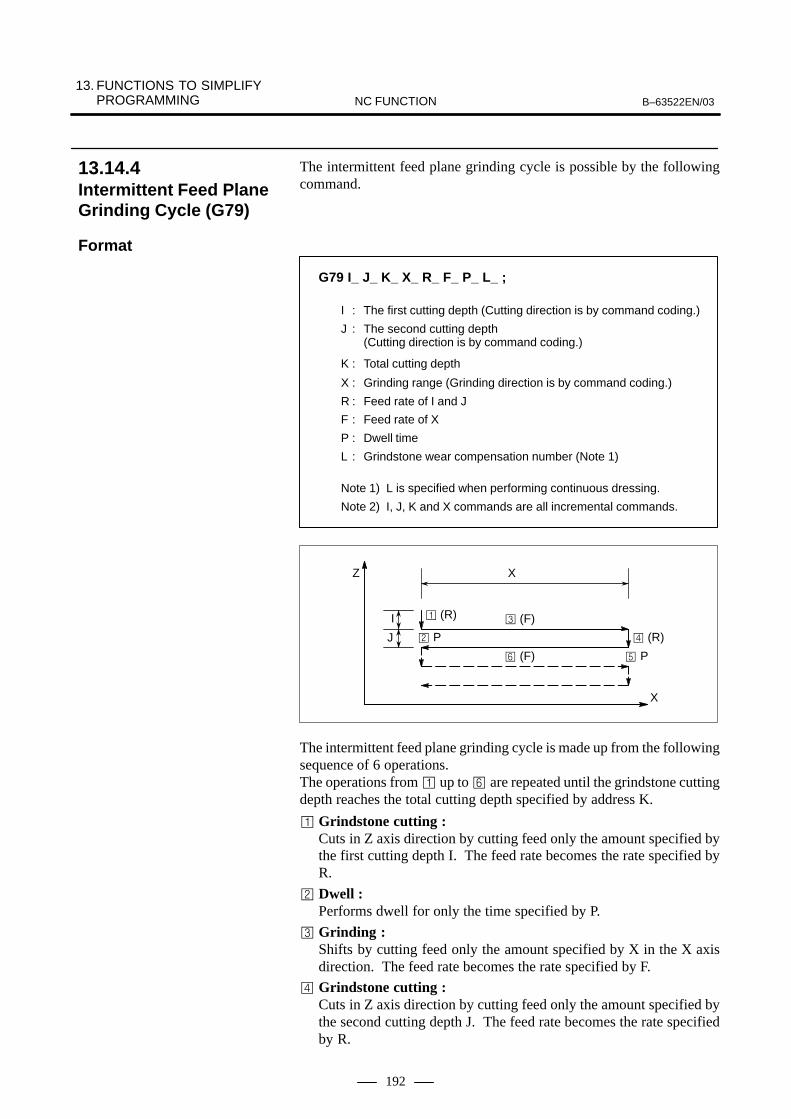
13. FUNCTIONS TO SIMPLIFY PROGRAMMING B–63522EN/03NC FUNCTION
192
The intermittent feed plane grinding cycle is possible by the followingcommand.
G79 I_ J_ K_ X_ R_ F_ P_ L_ ;
I : The first cutting depth (Cutting direction is by command coding.)
J : The second cutting depth (Cutting direction is by command coding.)
K : Total cutting depth
X : Grinding range (Grinding direction is by command coding.)
R : Feed rate of I and J
F : Feed rate of X
P : Dwell time
L : Grindstone wear compensation number (Note 1)
Note 1) L is specified when performing continuous dressing.
Note 2) I, J, K and X commands are all incremental commands.
I
J
X
� (R)
� P
� (F)
� P
X
Z
� (F)
� (R)
The intermittent feed plane grinding cycle is made up from the followingsequence of 6 operations. The operations from � up to � are repeated until the grindstone cuttingdepth reaches the total cutting depth specified by address K.
� Grindstone cutting :Cuts in Z axis direction by cutting feed only the amount specified bythe first cutting depth I. The feed rate becomes the rate specified byR.
� Dwell :Performs dwell for only the time specified by P.
� Grinding :Shifts by cutting feed only the amount specified by X in the X axisdirection. The feed rate becomes the rate specified by F.
� Grindstone cutting :Cuts in Z axis direction by cutting feed only the amount specified bythe second cutting depth J. The feed rate becomes the rate specifiedby R.
13.14.4Intermittent Feed PlaneGrinding Cycle (G79)
Format

13. FUNCTIONS TO SIMPLIFY PROGRAMMINGB–63522EN/03 NC FUNCTION
193
� Dwell :Performs dwell for only the time specified by P.
� Grinding (return direction) :Sent at rate specified by F in the reverse direction only the amountspecified by X.
In the case of a single block, the operations from � to � are performedby one cycle start.

13. FUNCTIONS TO SIMPLIFY PROGRAMMING B–63522EN/03NC FUNCTION
194
Controls cutting a certain fixed amount along the programmed figure forinput of external signals at the swing end point.
Z
x
y
G161 R_ ;
G160 ;
Figure program
G161R_ : Commands the operation mode and start of start of figure program. Further, specifies the cutting depth by address R.
Figure program : Programs the workpiece figure in the Y-Z plane byeither linear interpolation (G01) or by circular interpolation (G02, G03). Multiple blocks can be commanded.
G160 : Commands cancelling of operation mode (ending of figure program).
13.15INFEED CONTROL (M series)
M series
Format

13. FUNCTIONS TO SIMPLIFY PROGRAMMINGB–63522EN/03 NC FUNCTION
195
The repeat cutting can be made by the rotation or translation of a figurecommanded with a sub program.The plane for figure copying is selected by the plane selection commandsof G17, G18, and G19.
NOTEThe rotation copy cannot be commanded in the subprogramwhich commanded a rotation copy. Similarly, the translationcopy cannot be further commanded in a subprogram whichcommanded a translation copy.However, the translation copy and rotation copy can becommanded in the subprograms which commanded therotation copy and translation copy, respectively.
M series13.16FIGURE COPYING(G72.1, G72.2) (M series)

13. FUNCTIONS TO SIMPLIFY PROGRAMMING B–63522EN/03NC FUNCTION
196
The repeat cutting can be made by the rotation of a figure commandedwith a sub program using the following commands :Select the plane on which rotational copy will be performed, using planeselection commands G17, G18, and G19.
G17 G72.1 P_ L_ Xp_ Yp_ R_ ;
P : Sub program number
L : Number of repetitions
Xp : Xp axis center coordinate of rotation (Xp : X axis or the axis which is parallel to X axis)
Yp : Yp axis center coordinate of rotation (Yp : Y axis or the axis which is parallel to Y axis)
Zp : Zp axis center coordinate of rotation (Zp : Z axis or the axis which is parallel to Z axis)
R : Rotation angle (+ = Counterclockwise direction)
Xp–Yp plane
G18 G72.1 P_ L_ Zp_ Xp_ R_ ; Zp–Xp plane
G19 G72.1 P_ L_ Yp_ Zp_ R_ ; Yp–Zp plane
P6
P5
P4
R10
P3
P2
P1
P0
Y
X
Start point
Main program
O1000 ;N10 G92 X40.0 Y50.0 ;N20 G00 G90 X_ Y_ ; (P0)N30 G01 G17 G41 X_ Y_ D01 F10 ; (P1)N40 G72.1 P2000 L3 X0 Y0 R120.0 ;N50 G40 G01 X_ Y_ I_ J_ ; (P0)N60 G00 X40.0 Y50.0 ;N70 M30 ;
Sub program
O2000 G03 X_ Y_ R30.0 ; (P2)N100 G01 X_ Y_ ; (P3)N200 G03 X_ Y_ R10.0 ; (P4)N300 G01 X_ Y_ (P5)N400 G03 X_ Y_ R30.0 ; (P6)N500 M99 ;
13.16.1Rotation Copy (G72.1)
Format
Examples

13. FUNCTIONS TO SIMPLIFY PROGRAMMINGB–63522EN/03 NC FUNCTION
197
The repeat cutting can be made by the translation of a figure commandedwith a sub program using the following commands :Select the plane of linear copy with the plane selection commands G17,G18, and G19.
G17 G72.2 P_ L_ I_ J_ ;
P : Sub program number
L : Number of repetitions
I : Shift amount in Xp direction
J : Shift amount in Yp direction
K : Shift amount in Zp direction
Xp–Yp plane
G18 G72.2 P_ L_ K_ I_ ; Zp–Xp plane
G19 G72.2 P_ L_ J_ K_ ; Yp–Zp plane
P6
P5P4
70
P3P2P1
P0
Y
XStartpoint
Main program
O1000 ;N10 G92 X–20.0 Y0 ;N20 G00 G90 X0 Y0N30 G01 G17 G41 X_ Y_ D01 F10 ; (P0)N40 Y_ ; (P1)N50 X_ ; (P2)N60 G72.2 P2000 L3 I70.0 J0 ;N70 X_ Y_ ; (P8)N80 X0 ;N90 G00 G40 X–20.0 Y0 ;N100 M30 ;
Sub program
O2000 G90 G01 X_ ; (P3)N100 Y_ ; (P4)N200 G02 X_ I_ ; (P5)N300 G01 Y_ (P6)N400 X_ ; (P7)N500 M99 ;
P7
P8
70 70
13.16.2Linear Copy (G72.2)
Format
Examples

14. TOOL COMPENSATION FUNCTION B–63522EN/03NC FUNCTION
198
14 TOOL COMPENSATION FUNCTION

14. TOOL COMPENSATION FUNCTIONB–63522EN/03 NC FUNCTION
199
By using this function, shift amount between the reference positionassumed when programming and the actual tool position whenmachining, can be set as tool offset amount, thus allowing workpiecemachining according to the programmed size without changing theprogram.
Reference position(start point)
Z offset amount
X offset amount
The tool offset can be commanded to X, Y, and Z axes.
T20
T22T11
Setting value of offset number 1
Setting value of offset number 2
Programmed path
Offset path
The offset number is specified in the last one or two digit of the T code.Use parameters to select offset number digits (one or two).
� When offset number is specified with one digitT ��������
Offset number
Tool number
� When offset number is specified with two digitsT ��������
Offset number
Tool number
When the offset number is specified, the corresponding offset amount isselected, and tool offset starts. When 0 is selected as offset number, the tool offset is canceled.
14.1TOOL OFFSET (T series)
T series
14.1.1Tool Offset (T Code)
Explanations
� Offset number

14. TOOL COMPENSATION FUNCTION B–63522EN/03NC FUNCTION
200
The tool geometry compensation function compensates the tool figure ortool mounting position. The tool wear compensation functioncompensates the wear of a tool tip. These compensation amounts (offsetvalues) can be set separately. There are two types of geometrycompensation: So–called geometry compensation and the secondgeometry compensation that allows the user to specify whether to use thedirection directed by the PMC. The second geometry compensation isused to compensate for the difference in tool mounting position orselected position. If distinction between them is not necessary, the totalvalue of them is set as a tool position offset value.
Z-axis wearoffset value Z-axis geometry
offset value
X-axis wearoffset value
X-axisgeometryoffsetvalue
Point in the program
Tool geometry compensationdistinguished from tool wearcompensation
Point in the program
X-axisoffsetvalue
Z-axis offset value
Tool geometry compensationand tool wear compensationnot distinguished
In the system in which the Y axis is the fourth axis, the Y axis can becompensated by the tool offset value. When the tool geometry/wearcompensation option is specified, tool geometry/ware compensation isvalid for the Y-axis offset.
NOTE1 To use the Y-axis offset, the Y axis must be a linear axis.2 The direct input function of tool offset value or direct input
B function of tool compensation amount measured valuecannot be used for the Y-axis offset.
14.1.2Tool GeometryCompensation andTool WearCompensation
14.1.3Y Axis Offset

14. TOOL COMPENSATION FUNCTIONB–63522EN/03 NC FUNCTION
201
With this function, the programmed tool path can be offset when actuallymachining, for value of the tool radius set in the CNC. By programming machining pattern using this function (measuring cutterradius for actual cutting, and setting the value in the CNC as offset value),the tool can machine the programmed pattern, via the offset path. Thereis not need to change the program even when tool radius changes; justchange the offset value.
Work-piece
Profile
Toolnose
Tool center path
Cross points of line and line, arc and arc, line and arc is automaticallycalculated in the CNC to obtain offset actual tool path. So, Programmingbecomes simple, because it is only necessary to program the machiningpattern.
G40 : Tool nose radius compensation cancelG41 : Tool nose radius compensation leftG42 : Tool nose radius compensation right G41 and G42 are commands for tool nose radius compensation mode.The tool is offset to the left forward in the tool movement in G42 and rightforward in G42. Tool nose radius compensation is cancelled with G40.
Workpiece
G42
G41
X
Z
14.2TOOL NOSE RADIUSCOMPENSATION(G40, G41, G42)(T series)
T series
Explanations
� Tool nose radiuscompensation and itscancellation (G40, G41,G42)

14. TOOL COMPENSATION FUNCTION B–63522EN/03NC FUNCTION
202
The tool nose at position A in the following figure does not actually exist.The imaginary tool nose is required because it is usually more difficult toset the actual tool nose center to the start point than the imaginary toolnose. Also when imaginary tool nose is used, the tool nose radius neednot be considered in programming.
When programmed using the toolnose center
When programmed using theimaginary tool nose
A
Start pointStart point
The position relationship when the tool is set to the start point is shownin the following figure. The point of tool nose for start point or referencepoint i set in offset memory same as tool nose radius compensationamount.
0
6
8
1
5
4
2
7
3
0
6
8
1
5
4
2
7
3
0
6
8
1
5
4
2
7
3
0
6
8
1
5
4
2
7
3
Setting point of tool nose
Tool nose radius compensation amount and imaginary tool nose point canbe set in the tool nose radius compensation memory. When the last one or two digits of T code is commanded as offset number,corresponding tool nose radius compensation amount and imaginary toolnose point in the tool compensation memory is applied as the tool noseradius compensation amount and imaginary tool nose point for cutterradius compensation.
� Imaginary tool nose
� Tool nose radiuscompensation amountand assignment ofimaginary tool nosepoint (T code)

14. TOOL COMPENSATION FUNCTIONB–63522EN/03 NC FUNCTION
203
Cutter radius compensation is done on XY, ZX, YZ planes and on parallelaxes of X, Y, Z axes.Plane to perform tool nose radius compensation is selected with G17,G18, G19.
G17 : Xp-Yp plane Xp : X axis or the parallel axis G18 : Zp-Xp plane Yp : Y axis or the parallel axis G19 : Yp-Zp plane Zp : Z axis or the parallel axis
Parameters are used to set which parallel axis of the X, Y, Z axes is to bethe additional axis.
Tool overcutting is called ’interference’. This function checks whetherinterference occurs, if tool nose radius compensation is performed.
r
Programmedpath
Tool nosecenter path
OvercuttingOvercutting
During radius compensation for the tool tip, corner circular interpolation,with the specified compensation value used as the radius, can beperformed by specifying G39 in offset mode.
in offset mode, specify
G39 ;or
G39I_ J_I_ K_J_ K_
� Plane selection (G17, G18, G19)
� Interference check
14.3CORNER CIRCULAR INTERPOLATIONFUNCTION (G39)(T series)
T series
Format

14. TOOL COMPENSATION FUNCTION B–63522EN/03NC FUNCTION
204
By setting the difference between tool length assumed whenprogramming and the actual tool length as offsets, workpiece can bemachined according to the size commanded by the program, withoutchanging the program.
ÇÇÇÇÇÇÇÇ
ÇÇÇÇÇÇ
Reference tool
Difference set as offset value
G43 : Tool length compensation +G44 : Tool length compensation –G49 : Tool length compensation cancel
In G43 mode, the tool is offset to the + direction for the preset tool lengthoffset amount. In G44 mode, it is offset to the - direction for the presettool length offset amount. G49 cancels tool length compensation.
Tool length compensation can be performed for three types of axes.Compensation for the Z axis is tool length compensation A. That for theaxis vertical to the selected plane is tool length compensation B. That forthe axis specified by the G43 or G44 block is tool length compensationC. Which compensation to perform can be selected by a parameter.
The offset amount can be set in the tool length compensation memory.By specifying an offset number with the H code, offset amount loaded incorresponding tool length compensation memory is used as tool lengthcompensation amount.
Tool length compensation A
H_ ;G43G44
Tool length compensation B
H_ ;G17G18G19
G43G44
Tool length compensation C
α_ H_ ;G43G44 (alpha: arbitrary 1 axis)
14.4TOOL LENGTH COMPENSATION(G43, G44, G49)(M series)
M series
Explanations
� Tool lengthcompensation and itscancellation (G43, G44, G49)
� Tool lengthcompensation axis
� Assignment of offsetamount (H code)
Format
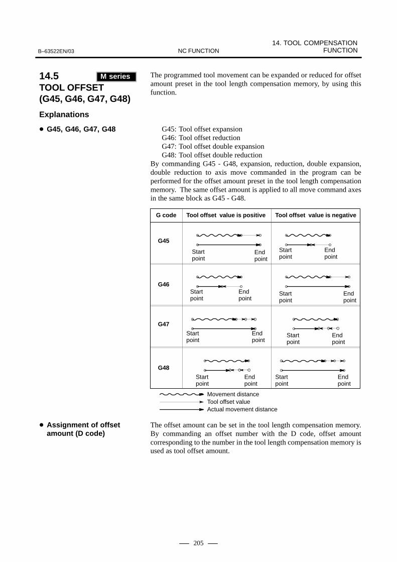
14. TOOL COMPENSATION FUNCTIONB–63522EN/03 NC FUNCTION
205
The programmed tool movement can be expanded or reduced for offsetamount preset in the tool length compensation memory, by using thisfunction.
G45: Tool offset expansionG46: Tool offset reductionG47: Tool offset double expansion G48: Tool offset double reduction
By commanding G45 - G48, expansion, reduction, double expansion,double reduction to axis move commanded in the program can beperformed for the offset amount preset in the tool length compensationmemory. The same offset amount is applied to all move command axesin the same block as G45 - G48.
G code Tool offset value is positive
Startpoint
Endpoint
G45
G46
G47
G48
Movement distanceTool offset valueActual movement distance
Tool offset value is negative
Startpoint
Startpoint
Startpoint
Endpoint
Endpoint
Endpoint
Startpoint
Startpoint
Startpoint
Startpoint
Endpoint
Endpoint
Endpoint
Endpoint
The offset amount can be set in the tool length compensation memory.By commanding an offset number with the D code, offset amountcorresponding to the number in the tool length compensation memory isused as tool offset amount.
14.5TOOL OFFSET (G45, G46, G47, G48)(M series)
M series
Explanations
� G45, G46, G47, G48
� Assignment of offsetamount (D code)

14. TOOL COMPENSATION FUNCTION B–63522EN/03NC FUNCTION
206
With cutter compensation B, inside of the sharp angle cannot be cut. Inthis case, an arc larger that the cutter radius can be commanded to thecorner by programming. Other functions are same as cutter radiuscompensation C.
With this function, the programmed tool path can be offset when actuallymachining, for value of the tool radius set in the CNC. By measuring cutting radius for actual cutting, and setting the value in theCNC as offset value, the tool can machine the programmed pattern, viathe offset path. There is no need to change the program even when toolradius changes; just change the offset value.
Programmed pathTool center path
Cross point
Cross points of line and line, arc and arc, line and arc is automaticallycalculated in the CNC to obtain offset actual tool path. So, programmingbecomes simple, because it is only necessary to program the machiningpattern.
G40 : Cutter radius compensation cancel G41 : Cutter radius compensation left G42 : Cutter radius compensation rightG41 and G42 are commands for cutter radius compensation mode. Thecutter is offset to the left forward in the cutter movement in G42 and rightforward in G42. Cutter radius compensation is cancelled with G40.
The offset amount can be set in the cutter radius compensation memory.When the D code is commanded as an offset number, corresponding offsetamount in the tool compensation memory is applied as the offset amountfor cutter radius compensation.The offset can be specified with an H code when the parameter is setaccordingly.
14.6CUTTERCOMPENSATION(M series)
M series
14.6.1Cutter Compensation B(G40 - 42)
14.6.2Cutter Compensation C(G40 - G42)
� Cutter compensation andits cancellation (G40, G41, G42)
� Assignment of offsetamount (D code)

14. TOOL COMPENSATION FUNCTIONB–63522EN/03 NC FUNCTION
207
Cutter radius compensation is done on XY, ZX, YZ planes and on parallelaxes of X, Y, Z axes.Plane to perform cutter radius compensation is selected with G17, G18,G19.
G17 : Xp-Yp plane G18 : Zp-Xp plane G19 : Yp-Zp plane
where Xp : X axis or its parallel axisYp : Y axis or its parallel axisZp : Z axis or its parallel axis
Parameters are used to set which parallel axis of the X, Y, Z axes is to bethe additional axis.
Plane to perform cutter radius compensation is decided in the axis addresscommanded in the G17, G18, or G19 block.
Example) (U, V, W axes are parallel axes of X, Y, Z axes respectively)
G17 X_ ; XY plane G17 U_ W_ ; UV plane G19 Y_ W_ ; YW plane
If axis address of Xp, Yp, or Zp was omitted, compensation plane isdecided regarding that X, Y, or Z was omitted.
Tool overcutting is called ’interference’. This function checks whetherinterference occurs, if cutter radius compensation is performed.
r
Programmedpath
Tool nosecenter path
OvercuttingOvercutting
� Plane selection (G17, G18, G19)
� Interference check

14. TOOL COMPENSATION FUNCTION B–63522EN/03NC FUNCTION
208
During cutter compensation B, C, corner circular interpolation, with thespecified compensation value used as the radius, can be performed byspecifying G39 in offset mode.
in offset mode, specify
G39 ;
G39 ;I_ J_I_ K_J_ K_
X_ Y_X_ Z_Y_ Z_
or
in offset mode, specify
G39 ;or
G39 ;I_ J_I_ K_J_ K_
14.7CORNER CIRCULAR INTERPOLATIONFUNCTION (G39)(M series)
M series
� Cutter compensation B
� Cutter compensation C

14. TOOL COMPENSATION FUNCTIONB–63522EN/03 NC FUNCTION
209
One of the tool compensation memory A/B/C can be selected accordingto offset amount.Tool offset amount range which can be set is as follows:
Incrementsystem
Geometry compensation Tool wear compensationIncrement
systemMetric input Inch input Metric input Inch input
IS-B ±999.999mm ±99.9999inch ±99.999mm ±9.9999inch
IS-C ±999.9999mm ±99.9999inch ±99.9999mm ±9.99999inch
There is no difference between geometry compensation memory and toolwear compensation memory in this tool compensation memory A.Therefore, amount of geometry offset and tool wear offset together is setas the offset memory. There is also no differences between cutter radiuscompensation (D code) and tool length compensation (H code).
Example
Offset number Compensation(geometry+wear)
D code/H code common
001 10.0 For D code
002 20.0 For D code
003 100.0 For H code
Memory for geometry compensation and tool ware compensation isprepared separately in tool compensation memory B. Geometrycompensation and tool wear compensation can thus be set separately.There is no difference between cutter radius compensation (D code) andtool length compensation (H code).
ÇÇÇÇÇÇÇÇ
OFSG : Geometry compensation
OFSW : Wear compensation
Referencepoint
OFSG
OFSW
14.8TOOLCOMPENSATIONMEMORY
14.8.1Tool CompensationMemory (M series)
M series
Explanations
� Tool compensationmemory A
� Tool compensationmemory B

14. TOOL COMPENSATION FUNCTION B–63522EN/03NC FUNCTION
210
Example
Offset number Geometrycompensation
Wearcompensation
D code/H codecommon
001 10.1 0.1 For D code
002 20.2 0.2 For D code
003 100.0 0.1 For H code
Memory for geometry compensation as well as tool wear compensationis prepared separately in tool compensation memory C. Geometrycompensation and tool wear compensation can thus be set separately.Separate memories are prepared for cutter radius compensation (for Dcode) and for tool length compensation (for H code).
Example
OffsetFor D code For H code
Offsetnumber Geometry
compensationWear
compensationGeometry
compensationWear
compensation
001 10.0 0.1 100.0 0.1
002 20.0 0.2 300.0 0.3
There are two types of tool offset amount memory, which can be selectedaccording to offset amount.Tool offset amount range which can be set is as follows:
Incrementsystem
Tool compensation valueIncrement
systemMetric input (mm) Inch input (inch)
IS-B –999.999 to +999.999 –99.9999 to +99.9999
IS-C –999.9999 to +999.9999 –99.99999 to +99.99999
The maximum wear compensation value can, however, be modified usinga parameter.
The number of digits used to specify a tool geometry/wear compensationvalue can be expanded by selecting the option which enables seven–digittool offset specification. When this option is used, tool compensationvalues can be specified using up to seven digits for IS–B and eight digitsfor IS–C. The valid data range for tool compensation values will thus beas listed in the following table.
Incrementsystem
Tool compensation valueIncrement
systemMetric input (mm) Inch input (inch)
IS-B 0 to ±9999.999 0 to ±999.9999
IS-C0 to ±9999.9999(0 to ±4000.0000)
0 to ±999.99999(0 to ±160.00000)
� Tool compensationmemory C
14.8.2Tool Offset AmountMemory (T series)
T series

14. TOOL COMPENSATION FUNCTIONB–63522EN/03 NC FUNCTION
211
NOTE1 The range enclosed in parentheses applies when automatic
inch/metric conversion is enabled.2 The option enabling seven–digit tool offset specification
cannot be used for B–axis offsets for B–axis control.
No distinction is made between the memory for geometry compensationvalues and that for wear compensation values. The total of the geometrycompensation value and wear compensation value for a tool is stored incompensation memory.
Example
Offsetnumber
X axisoffset
amount
Z axisoffset
amount
Y axisoffset
amount
Amount oftool nose
compensation
Imaginarytool nosenumber
01 10.0 100.1 0 0.5 3
02 20.2 150.3 0 0.7 2
03 30.4 200.5 0 1.0 8
Memory for geometry offset and tool wear offset is prepared separately.Geometry offset and tool wear offset can thus be set separately.
ÇÇÇÇÇÇÇÇÇ
Z axis wear offset Z axis geometry offset
X axis geometry offset
X axis wear offset
Offsetnumber
X axis offset value
Z axis offset value
Y axis offset value
Tool nose radiuscompensation
value
Imaginarytool nosenumber
Geometryoffset
Wearoffset
Geometryoffset
Wearoffset
Geometryoffset
Wearoffset
Geometryoffset
Wearoffset
01 10.0 0.0 100.0 0.1 0 0 0.4 0.1 3
02 20.2 0.2 150.0 0.3 0 0 0.5 0.2 2
03 30.4 0.4 200.0 0.5 0 0 1.2 –0.2 8
Explanations
� Tool geometry/wearcompensation option notspecified
� Tool geometry/wearcompensation optionspecified

14. TOOL COMPENSATION FUNCTION B–63522EN/03NC FUNCTION
212
� 32 tool offsets (standard)Offset numbers (D code/H code) 0 - 32 can be used.D00 - D32, or H00 - H32
� 64 tool offsets (optional)Offset numbers (D code/H code) 0 - 64 can be used.D00 - D64, or H00 - H64
� 99 tool offsets (optional)Offset numbers (D code/H code) 0 - 99 can be used.D00 - D99, or H00 - H99
� 200 tool offsets (optional)Offset numbers (D code/H code) 0 - 200 can be used. D00 - D200, or H00 - H200
� 400 tool offsets (optional)Offset numbers (D code/H code) 0 - 400 can be used. D00 - D400 or H00 - H400
� 499 tool offsets (optional)Offset numbers (D code/H code) 0 - 499 can be used. D00 - D499, or H00 - H499
� 999 tool offsets (optional)Offset numbers (D code/H code) 0 - 999 can be used. D00 - D999 or H00 - H999
� 16 tool offsets (standard)Offset numbers 0 - 16 can be used.
� 32 tool offsets (optional)Offset numbers 0 - 32 can be used.
� 64 tool offsets (optional)Offset numbers 0 - 64 can be used.
� 99 tool offsets (optional)Offset numbers 0 - 99 can be used.
� 400 tool offsets (optional)Offset numbers 0 – 400 can be used.
� 999 tool offsets (optional)Offset numbers 0 – 999 can be used.
NOTE1 For the tool post interference check (between two paths), up
to 64 tool offsets can be displayed or set for tool figure data.2 For 400 or 999 tool offsets, the tool offset number is
specified for the three low–order digits of the T code.
14.9NUMBER OF TOOLOFFSETS
14.9.1Number of Tool Offsets (M series)
M series
14.9.2Number of Tool Offsets(T series)
T series

14. TOOL COMPENSATION FUNCTIONB–63522EN/03 NC FUNCTION
213
Tool offset amount can be set/changed with the G10 command. When G10 is commanded in absolute input (G90), the commanded offsetamount becomes the new tool offset amount. When G10 is commandedin incremental input (G91), the current tool offset amount plus thecommanded offset amount is the new tool offset amount.
G10 L11 P_ R_ ;
P_ : Offset numberR_ : Tool offset amount
G10 L10 P_ R_ ;
Setting/changing of geometry offset amount
G10 L11 P_ R_ ;
Setting/changing of tool wear offset amount
G10 L10 P_ R_ ;
Setting/changing of geometry offset amount for H code
G10 L12 P_ R_ ;
Setting/changing of geometry offset amount for D code
G10 L11 P_ R_ ;
Setting/changing of tool wear offset amount for H code
G10 L13 P_ R_ ;
Setting/changing of tool ware offset amount for D code
NOTEL1 may be used instead of L11 for the compatibility with theconventional CNC’s format.
14.10CHANGING OF TOOLOFFSET AMOUNT(PROGRAMMABLEDATA INPUT) (G10)
Format (M series)
� Tool compensationmemory A
� Tool compensationmemory B
� Tool compensationmemory C

14. TOOL COMPENSATION FUNCTION B–63522EN/03NC FUNCTION
214
G10 P_ X_ Y_ Z_ R_ Q_ ;or
G10 P_ U_ V_ W_ C_ Q_ ;
P : Offset number1–64 :Tool wear offset number10000+(1–64) : Tool geometry offset number+10000
X : Offset value on X axis (absolute)Y : Offset value on Y axis (absolute)Z : Offset value on Z axis (absolute)U : Offset value on X axis (incremental)V : Offset value on Y axis (incremental)W : Offset value on Z axis (incremental)R : Tool nose radius offset value (absolute)C : Tool nose radius offset value (incremental)Q : Imaginary tool nose number
In an absolute command, the values specified in addresses X, Y , Z, andR are set as the offset value corresponding to the offset number specifiedby address P. In an incremental command, the value specified inaddresses U, V, W, and C is added to the current offset valuecorresponding to the offset number.
NOTE1 Addresses X, Y, Z, U, V, and W can be specified in the same
block.2 Use of this command in a program allows the tool to
advance little by little. This command can also be used inputoffset values one at a time from a tape by specifying thiscommand successively instead of inputting these valuesone at a time from the MDI unit.
Format (T series)

14. TOOL COMPENSATION FUNCTIONB–63522EN/03 NC FUNCTION
215
The grinding-wheel cutting and dresser cutting are compensatedcontinuously during grinding in the canned cycles for surface grinding(G75, and G77 to G79). They are compensated according to the amountof continuous dressing.
X
V
The offset number (grinding-wheel wear compensation number) isspecified by address L in the block for the canned cycles for surfacegrinding. The compensation amount set in the offset memorycorresponding to the specified number is the dressing amount.
Compensation is performed for each cutting operation (each X-axismovement) in the canned cycles for grinding. Along with X-axismovement, compensation is performed both in Y-axis direction(grinding-wheel cutting) and that in V-axis direction (dresser cutting).That is, compensation is performed for interpolation for the threecoordinates simultaneously. The Y-axis movement amount(compensation amount) is the specified dressing amount. The V-axismovement amount is twice the specified dressing amount (diameter).
a
2a
X
X
YV
Dresser
Grindingwheel
a : Dressing amount
Workpiece
14.11GRINDING-WHEELWEARCOMPENSATION BYCONTINUOUSDRESSING (M series)
M series
Explanations
� Specification
� Compensation

14. TOOL COMPENSATION FUNCTION B–63522EN/03NC FUNCTION
216
In cutter compensation C, two–dimensional offsetting is performed for aselected plane. In three–dimensional tool compensation, the tool can beshifted three–dimensionally when a three–dimensional offset direction isprogrammed.
When the following command is executed in the cutter compensationcancel mode, the three–dimensional tool compensation mode is set :
Xp : X–axis or a parallel axis
Yp : X–axis or a parallel axis
Zp : Z–axis or a parallel axis
G41 Xp_ Yp_ Zp_ I_ J_ K_ D_ ;
When the following command is executed in the three–dimensionaltool compensation mode, the cutter compensation cancel mode is set :
G40 Xp_ Yp_ Zp_ ;
When canceling the three–dimensional tool compensation mode andtool movement at the same time
or
Xp_ Yp_ Zp_ D00 ;
G40 ;
D00 ;
When only canceling the vector
or
The three–dimensional space where three–dimensional tool com-pensation is to be executed is determined by the axis addresses spe-cified in the start–up block containing the G41 command. If Xp, Yp, orZp is omitted, the corresponding axis, X–, Y–, or Z– axis (the basicthree axis), is assumed.
(Example)When the U–axis is parallel to the X–axis, the V–axis is parallel to theY–axis, and the W–axis is parallel to the Z–axis
G41 X_ I_ J_ K_ D ;
G41 U_ V_ Z_ I_ J_ K_ D_ ;
G41 W_ I_ J_ K_ D ;
XYZ space
UVZ space
XYW space
14.12THREE–DIMENSIONAL TOOL COMPENSATION(G40, G41) (M series)
M series
Format
� Start–up(Startingthree–dimensional toolcompensation)
� Cancelingthree–dimensional toolcompensation
� Selecting offset space
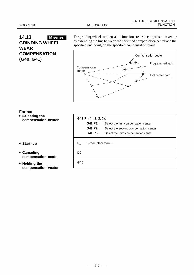
14. TOOL COMPENSATION FUNCTIONB–63522EN/03 NC FUNCTION
217
The grinding wheel compensation function creates a compensation vectorby extending the line between the specified compensation center and thespecified end point, on the specified compensation plane.
Compensation vector
Programmed path
Tool center path
Compensation center
G41 Pn (n=1, 2, 3);
G41 P1; Select the first compensation center
G41 P2; Select the second compensation center
G41 P3; Select the third compensation center
D_; D code other than 0
D0;
G40;
� Selecting thecompensation center
� Start–up
� Cancelingcompensation mode
� Holding thecompensation vector
14.13GRINDING WHEEL WEARCOMPENSATION(G40, G41) (M series)
M series
Format

14. TOOL COMPENSATION FUNCTION B–63522EN/03NC FUNCTION
218
When a five–axis machine that has two axes for rotating the tool is used,tool length compensation can be performed in a specified tool axisdirection on a rotation axis. When a rotation axis is specified in tool axisdirection tool length compensation mode, tool length compensation isapplied in a specified tool axis direction on the rotation axis by thecompensation value specified in the H code. The tool compensation vector changes as the offset value changes ormovement is made on a rotation axis. When the tool compensation vectorchanges, movement is made according to the change value along theX–axis, Y–axis, and Z–axis.
����� �� �
� : Offset number
�� �
14.14TOOL AXIS DIRECTION TOOL LENGTHCOMPENSATION
Format
� Tool axis direction toollength compensation
� Tool axis direction toollength compensationcancellation
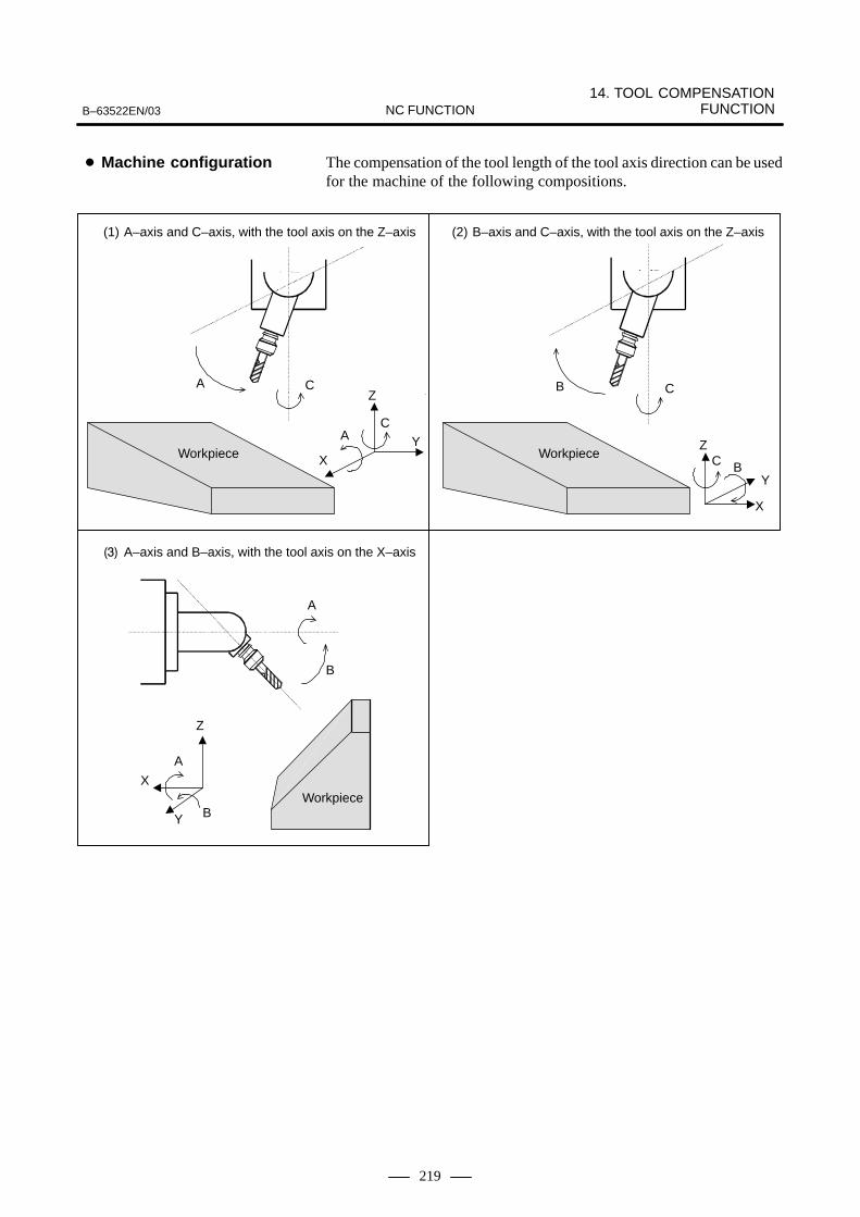
14. TOOL COMPENSATION FUNCTIONB–63522EN/03 NC FUNCTION
219
The compensation of the tool length of the tool axis direction can be usedfor the machine of the following compositions.
C B
Z
Y
X
CB
B
A
Z
Y
X
A
B
CA
Z
XY
CA
Workpiece
(1) A–axis and C–axis, with the tool axis on the Z–axis (2) B–axis and C–axis, with the tool axis on the Z–axis
��� A–axis and B–axis, with the tool axis on the X–axis
Workpiece
Workpiece
� Machine configuration

14. TOOL COMPENSATION FUNCTION B–63522EN/03NC FUNCTION
220
��� A–axis and B–axis, with the tool axis on the Z–axis, and the B–axis used as the master
(5) A–axis and B–axis, with the tool axis on the Z–axis, and the A–axis used as the master
B
A
Z
YX
B
A
B
A
Z
X
Y
�
�
Workpiece Workpiece
A tool compensation vector is found from the coordinates on the rotationaxes for controlling the tool axis direction. However, the configurationof some machines is such that the tool axis is inclined using a fixedattachment. In such a case, the rotation angles of the rotation axes can beset using parameters.
The machine–specific length from the rotation center of the tool rotationaxes (A– and B–axes, A– and C–axes, and B– and C–axes) to the toolmounting position is referred to as the tool holder offset. Unlike a toollength offset value, a tool holder offset value is set in parameter No. 7648.When tool axis direction tool length compensation is applied, the sum ofthe tool holder offset and tool length offset is handled as a tool length forcompensation calculation.
Tool holder offset
Tool length offset
Rotation center
Toollength
This function compensates for a slight shift of the rotation axis origincaused, for example, by thermal displacement. .Set offsets relative to the rotation angles of the rotation axes in parameter.
� Parameter–basedrotation anglespecification
� Tool holder offset
� Rotation axis origincompensation androtation axis offset

14. TOOL COMPENSATION FUNCTIONB–63522EN/03 NC FUNCTION
221
The three–dimensional cutter compensation function is used withmachines that can control the direction of tool axis movement by usingrotation axes (such as the B– and C–axes). This function performs cuttercompensation by calculating a tool vector from the positions of therotation axes, then calculating a compensation vector in a plane(compensation plane) that is perpendicular to the tool vector.There are two types of cutter compensation: Tool side compensation andleading edge compensation. Which is used depends on the type ofmachining.
Tool side compensation is a type of cutter compensation that performsthree–dimensional compensation on a plane (compensation plane)perpendicular to a tool direction vector.
���� �� � �� �� �
When type C is selected for the startup operation or cancel opera-tion, the move command such as X_Y_Z_ must not be specified inthe G41.2 block.
��� �� � �� �� �
When type C is selected for the startup operation or cancel opera-tion, the move command such as X_Y_Z_ must not be specified inthe G42.2 block.
��� �� � �� �
Compensationplane
YZ
X
Tool vector
Cutter compensation amount
Tool center path (after compensation)
Programmed tool path(before compensation)
Cutter compensationvector
14.15THREE–DIMENSIONALCUTTERCOMPENSATION
14.15.1Tool SideCompensation
Format
� Tool side compensation(left side)
� Tool side compensation(left side)
� Tool side compensationcancellation
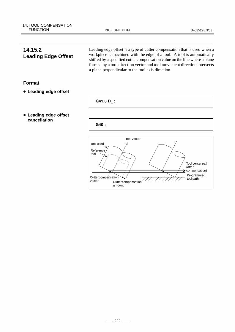
14. TOOL COMPENSATION FUNCTION B–63522EN/03NC FUNCTION
222
Leading edge offset is a type of cutter compensation that is used when aworkpiece is machined with the edge of a tool. A tool is automaticallyshifted by a specified cutter compensation value on the line where a planeformed by a tool direction vector and tool movement direction intersectsa plane perpendicular to the tool axis direction.
����� �� �
��� �
Tool used
Referencetool
Cutter compensationvector Cutter compensation
amount
Tool center path(after compensation)
Programmedtool pathtool path
Tool vector
14.15.2Leading Edge Offset
Format
� Leading edge offset
� Leading edge offsetcancellation
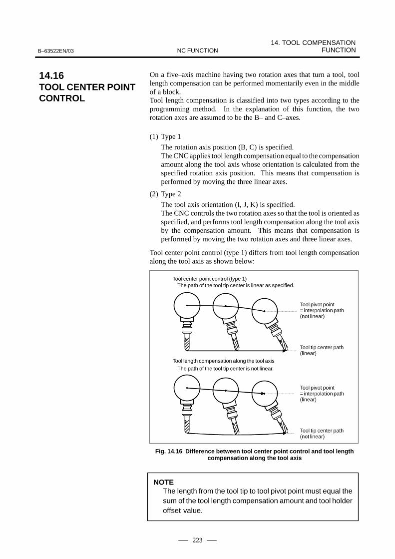
14. TOOL COMPENSATION FUNCTIONB–63522EN/03 NC FUNCTION
223
On a five–axis machine having two rotation axes that turn a tool, toollength compensation can be performed momentarily even in the middleof a block.Tool length compensation is classified into two types according to theprogramming method. In the explanation of this function, the tworotation axes are assumed to be the B– and C–axes.
(1) Type 1
The rotation axis position (B, C) is specified.The CNC applies tool length compensation equal to the compensationamount along the tool axis whose orientation is calculated from thespecified rotation axis position. This means that compensation isperformed by moving the three linear axes.
(2) Type 2
The tool axis orientation (I, J, K) is specified.The CNC controls the two rotation axes so that the tool is oriented asspecified, and performs tool length compensation along the tool axisby the compensation amount. This means that compensation isperformed by moving the two rotation axes and three linear axes.
Tool center point control (type 1) differs from tool length compensationalong the tool axis as shown below:
Tool center point control (type 1)The path of the tool tip center is linear as specified.
Tool length compensation along the tool axisThe path of the tool tip center is not linear.
Tool pivot point= interpolation path(not linear)
Tool tip center path(linear)
Tool pivot point= interpolation path(linear)
Tool tip center path(not linear)
Fig. 14.16 Difference between tool center point control and tool lengthcompensation along the tool axis
NOTEThe length from the tool tip to tool pivot point must equal thesum of the tool length compensation amount and tool holderoffset value.
14.16TOOL CENTER POINTCONTROL

14. TOOL COMPENSATION FUNCTION B–63522EN/03NC FUNCTION
224
G43.4 H� �
H : Offset number
G43.5 I_ J_ K_ H_ Q� �
I,J,K : Tool axis orientation
H : Offset number
Q : Tool inclination angle (degrees)
NOTE1 When I, J, and K are all omitted from a block, the
compensation vector in the previous block is used.2 When any of I, J, and K is omitted, the omitted I, J, or K is
assumed to be 0.3 Movement of the rotation axes is controlled by shortcut
control so that the amount of movement does not exceed180.
�� �
The rotary table dynamic fixture offset function saves the operator thetrouble of re–setting the workpiece coordinate system when the rotarytable rotates before cutting is started. With this function the operatorsimply sets the position of a workpiece placed at a certain position on therotary table as a reference fixture offset. If the rotary table rotates, thesystem automatically obtains a current fixture offset from the angulardisplacement of the rotary table and creates a suitable workpiececoordinate system. After the reference fixture offset is set, the workpiececoordinate system is prepared dynamically, wherever the rotary table islocated.The zero point of the workpiece coordinate system is obtained by addingthe fixture offset to the offset from the workpiece reference point.
G54.2 Pn ;Pn : Reference fixture offset value number (1 to 8)
If n is set to 0, the fixture offset becomes invalid.
Format
� Specifying tool centerpoint control (type 1)
� Specifying tool centerpoint control (type 2)
� Canceling tool centerpoint control
14.17ROTARY TABLE DYNAMIC FIXTURE OFFSET
Format
� Fixture offset command

15. ACCURACY COMPENSATION FUNCTIONB–63522EN/03 NC FUNCTION
225
15 ACCURACY COMPENSATION FUNCTION

15. ACCURACY COMPENSATION FUNCTION B–63522EN/03NC FUNCTION
226
The errors caused by machine position, as pitch error of the feed screw,can be compensated. This function is for better machining precision.As the offset data are stored in the memory as parameters, compensationsof dogs and settings can be omitted. Offset intervals are set constant byparameters (per axis).
This function can perform compensation as described below.
� Compensation period: Constant period for each axis (parametersettings (for each axis))
� Compensation points: Total of 1,024 pointsOptional distribution to each axis(parameter settings (for each axis))
� Amount of compensation: The following compensation pulse isoutput at each compensation point.
Compensation pulse = (–7 to +7) � (compensation magnification)
Unit: Same as the detection unit
–7 to +7: Setting for each compensation point (setting withinthe range of –7 to +7)
Compensation magnification: 1 to 100 timesConstant magnification for each axis (parametersettings (for each axis))
In bi–directional pitch error compensation, different pitch errorcompensation amounts can be set for travel in the positive direction andthat in the negative direction, so that pitch error compensation can beperformed differently in the two directions, in contrast to stored pitcherror compensation, which does not distinguish between the directions oftravel. In addition, when the direction of travel is reversed, thecompensation amount is automatically calculated from the pitch errorcompensation data to perform compensation in the same way as inbacklash compensation. This reduces the difference between the paths inthe positive and negative directions.
Bi–directional pitch error compensation allows use of 0 to 1023,3000 to4023 as compensation points.This function has expanded the compensation points to 0 to 2559,3000to 5559.
15.1STORED PITCH ERRORCOMPENSATION
15.2BI–DIRECTIONALPITCH ERROR COMPENSATION
Expanded compensationpoints in bi–directionalpitch errorcompensation

15. ACCURACY COMPENSATION FUNCTIONB–63522EN/03 NC FUNCTION
227
Stored pitch error compensation outputs a pitch error compensation pulsefor each pitch error compensation point at compensation point intervals.(See Fig. 15.3 (a).)Interpolation type pitch error compensation outputs one to several pulsesto indicate the amount of compensation at each error compensation pointduring each error compensation point period. (See Fig. 15.3 (b).)
Pitch error compensation point period
P0: Machine zero point P1 P2 P3
ε1
ε1, ε2, ε3 : Pitch error compensation amounts
P1, P2, P3 :Pitch error compensation points
ε2
ε3
(Parameter No. 3624)
Fig. 15.3 (a) Method of stored pitch error compensation
ε1 ε2 ε3
Pitch error compensation point period
P0: Machine zero point P1 P2 P3
ε1, ε2, ε3 : Pitch error compensation amounts
P1, P2, P3 :Pitch error compensation points(Parameter No. 3624)
Fig. 15.3 (b) Method of interpolation type pitch error compensation
15.3INTERPOLATIONTYPE PITCH ERRORCOMPENSATION

15. ACCURACY COMPENSATION FUNCTION B–63522EN/03NC FUNCTION
228
When a pitch error of a feed screw has a constant slope, you only need toselect four representative points (a, b, c, d) from pitch error compensationpoints and set slope data for the four points; unlike pitch errorcompensation, you need not set compensation data for everycompensation point. Then, compensation data at each compensationpoint is calculated automatically for compensation. (When movementalong an axis for which slope compensation data is set is made,compensation is performed for that axis.)Pitch error compensation is required to use this function.
b
�
c
d
On a machine having a long stroke, machining precision may be reducedif the straightness of the axes is poor. The straightness compensationfunction compensates an axis in detection units while the tool is movingalong another axis, thus improving machining precision.Moving the tool along an axis (the movement axis, specified with aparameter) compensates another axis (the compensation axis, specifiedwith a parameter) within the range for pitch error compensation for themovement axis.
Pitch error compensation points along the movement axis
… …
Example:
0 1 2 3 60 61 126 127
Machine coordinates along the movement axis
… …
a c
α
β
γ
b d
ε
a, b, c, d : Compensation point numbers for the movement axis (same as the numbers of the pitch error compensation points)
α, β, γ, ε : Compensation value for each compensation point number (the amount of compensation performed for the compensation axis)
The compensation value applied to the compensation axis is (β – α)/(b –a) for the range between points a and b.
15.4INCLINATIONCOMPENSATION
15.5STRAIGHTNESSCOMPENSATION

15. ACCURACY COMPENSATION FUNCTIONB–63522EN/03 NC FUNCTION
229
Suppose a table having a ball thread in the Y–axis direction which isplaced on a ball thread in the X–axis direction. When the ball thread inthe X–axis direction has a constant slope because of deflection and soforth, the Y–axis that moves on the X–axis ball thread has an influenceof the slope of the X–axis ball thread. As a result, the accuracy of theY–axis lowers (Fig. 15.5 (a)).When straightness compensation is used where the X–axis is set as themovement axis and the Y–axis set as the compensation axis, the Y–axis(the compensation axis) position is compensated according to the X–axis(the movement axis) position, which can improve the accuracy (Fig. 15.5(b)).
X–axis
��, ��, ��� �� : Points on the movement axis
Structurally, the locus of portion B that connects the X–axis and Y–axisis influenced by the slope of the X–axis. When a movement from P1to P4 along only the X–axis is specified without straightness com-pensation, the locus of point A on the Y–axis is influenced by the slopeof the X–axis.
P1 P4
A
B
P3P2
Locus ofportion B
Locus of point A
Y–axis
Fig. 15.5 (a)
Explanations

15. ACCURACY COMPENSATION FUNCTION B–63522EN/03NC FUNCTION
230
ε�
P1 P4Y–axis P3P2
Locus ofportion B
�–axis
Locus of point A
P1, P2, P3, P4 : Compensation points for the movement axisε1, ε2, ε3, ε4 : Compensation amounts for the compensation points
along the compensation axisWhen a movement from P1 to P4 along only the X–axis (the move-ment axis) is specified, straightness compensation is applied to theY–axis (the compensation axis) by corresponding compensationamounts (1 to (4 as portion B moves to P1 to P2 to P3 to P4. Thiscompensation operation for the Y–axis makes the locus of point A onthe Y–axis free from the influence of the X–axis slope even when thelocus of portion B that connects the X–axis and Y–axis is influencedby the X–axis slope.
A
B ε�
ε�
ε3
ε�
ε�
ε3
ε�
Fig. 15.5 (b)
NOTE1 Straightness compensation is enabled once reference
position return has been performed along the movementand compensation axes.
2 When the optional straightness compensation function isused, the optional storage pitch error compensationfunction is required.
3 Straightness compensation data is added to the storagepitch error compensation data when output.
4 In straightness compensation, the movement axis itselfcannot be set as the compensation axis. To apply such aform of compensation, use slope compensation.

15. ACCURACY COMPENSATION FUNCTIONB–63522EN/03 NC FUNCTION
231
These compensation functions all perform compensation at eachcompensation point according to the machine position by dividingmachine strokes by the parameter–set compensation interval. Inclinationcompensation and straightness compensation use the compensationinterval and compensation point numbers of pitch error compensation butuse different compensation amounts that are prepared separately for theinclination compensation function and straightness compensationfunction.
In pitch error compensation, a compensation amount is set for eachcompensation point in advance. At each compensation point, thecorresponding compensation amount is output.
With bi–directional pitch error compensation, the compensation amountcan be changed according to the axis move direction. In interpolation typepitch error compensation, compensation pulses are output even betweencompensation points, so smoother pitch error compensation is possible.
In inclination compensation, a compensation amount is not set for eachcompensation point; instead, compensation amounts are set forrepresentative four points (a, b, c, d) (compensation points for inclinationcompensation) selected from the compensation points for pitch errorcompensation. At compensation points for pitch error compensationlocated between the compensation points for inclination compensation,the NC calculates and outputs the compensation amount according to thecompensation amount for inclination compensation. Inclinationcompensation can be applied when pitch errors have a constantinclination.
b
a
c
d
15.6ADIFFERENCEAMONG PITCHERRORCOMPENSATION,INCLINATIONCOMPENSATION,AND STRAIGHTNESSCOMPENSATION
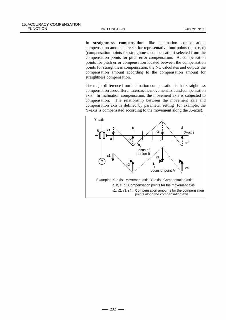
15. ACCURACY COMPENSATION FUNCTION B–63522EN/03NC FUNCTION
232
In straightness compensation, like inclination compensation,compensation amounts are set for representative four points (a, b, c, d)(compensation points for straightness compensation) selected from thecompensation points for pitch error compensation. At compensationpoints for pitch error compensation located between the compensationpoints for straightness compensation, the NC calculates and outputs thecompensation amount according to the compensation amount forstraightness compensation.
The major difference from inclination compensation is that straightnesscompensation uses different axes as the movement axis and compensationaxis. In inclination compensation, the movement axis is subjected tocompensation. The relationship between the movement axis andcompensation axis is defined by parameter setting (for example, theY–axis is compensated according to the movement along the X–axis).
Example : X–axis: Movement axis, Y–axis: Compensation axis
a, b, c, d : Compensation points for the movement axis
ε1, ε2, ε3, ε4 : Compensation amounts for the compensationpoints along the compensation axis
a
d
A
B
c
b
Locus ofportion B
�–axis
Locus of point A
ε�
ε�
ε�
ε4
Y–axis
ε1
ε2
ε3
ε4

15. ACCURACY COMPENSATION FUNCTIONB–63522EN/03 NC FUNCTION
233
This function is used to compensate lost motions proper to the machinesystem. Offset amounts come in a range of 0 to ±9999 pulses per axis,and is set as parameters in detection unit.
Since different backlash compensation values can be used for cutting feedand rapid traverse, the machining precision is improved.The following table shows backlash amounts according to the feedrateand movement direction. In the table, the backlash compensation amountfor cutting feed is A, and that for rapid traverse is B. A and B are set inparameters.
Cuttingfeed
↓Cutting
feed
Rapid traverse
↓Rapid
traverse
Rapid traverse
↓Cutting
feed
Cuttingfeed
↓Rapid
traverse
Movement in same direction 0 0 ±α ±(–α)
Movement in opposite directions ±A ±B ±(B+α) ±(B+α)
*1) α=(A–B) / 2
*2) Sings (+ and –) indicate directions.
ÙÙÙÙÙÙÙÙÙÙÙÙÙÙÙÙÙÙÙÙÙÙÙÙÙÙÙÙÙÙÙÙÙÙÙÙÙÙÙÙÙÙ
ÙÙÙÙÙÙÙÙÙÙÙÙÙÙÙÙÙÙÙÙÙÙÙÙÙÙÙÙÙÙÙÙÙÙÙÙÙÙÙÙÙÙ
α α
Stop in cutting feed
A
Cutting feed
Stop in rapid traverse
B
α : Excess of machine movement
Rapid traverse
15.7BACKLASHCOMPENSATION
15.8BACKLASHCOMPENSATIONSPECIFIC TO RAPID TRAVERSE AND CUTTING FEED

15. ACCURACY COMPENSATION FUNCTION B–63522EN/03NC FUNCTION
234
Parameters and pitch errors data can be set by programs. therefore,following uses can be done example.
� Parameter setting such as pitch errors compensation data, etc. whenthe attachment is replaced.
� Parameters such as max. cutting speed and cutting feed time constantcan be changed according to the machining conditions.
G10 L50 ;N_ R_ ; Input of parameters except axis typeN_ P_ R_ ; Input of axis type parameters :G11 ;
G10 L50 : Parameter input mode
G11 : Parameter input mode cancel
N_ : Parameter No. (or pitch error data No.+10000)
P_ : Axis No. (in the case of axis type parameter)
R_ : Parameter setting value (or pitch error data)
NOTESome parameters cannot be set.
15.9PROGRAMMABLEPARAMETER ENTRY (G10, G11)
Format
15. ACCURACY COMPENSATION FUNCTIONB–63522EN/03 NC FUNCTION
235
The following two functions are available:
<1> 128 straightness compensation points
<2> Interpolated straightness compensation
In conventional straightness compensation, compensation data is set forfour compensation points with parameters to obtain compensation dataalong an approximate straight line connecting the four points and performcompensation based on the data.
This function allows data for up to 128 equally spaced compensationpoints to be set in the same way as for ordinary pitch error compensation.By this function, fine compensation is also available for ”straightnesscompensation.”
This function also allows up to six combinations of movement andcompensation axes for straightness compensation.
In conventional straightness compensation, for each interval betweenpitch error compensation points set by parameters, the amount of allstraightness compensation at the compensation point is output andcompensation is performed.
This function equally divides the amount of compensation for eachinterval between pitch error compensation points for compensation dataset using 128 straightness compensation points and outputs it as acompensation pulse.
NOTETo add the interpolated straightness compensation option,the stored pitch error compensation option is also required.
15.10INTERPOLATEDSTRAIGHTNESSCOMPENSATION
128 straightnesscompensation points
Interpolated straightnesscompensation

16. COORDINATE SYSTEM CONVERSION B–63522EN/03NC FUNCTION
236
16 COORDINATE SYSTEM CONVERSION

16. COORDINATE SYSTEM CONVERSIONB–63522EN/03 NC FUNCTION
237
Patterns specified by the program can be rotated. For example, by usingthis function, when the attached workpiece comes in a position which issomewhat rotated from the machine coordinates, the position can becompensated by the rotation instruction.If a pattern is similar to that made by rotating a programmed figure, theprogram for the pattern can be created by calling the program for the figureas a sub program, and rotating the coordinates in the program. Thisfunction reduces the programming time and program length.
Rotation angle
Rotationcenter
Y
X0
α, β : Coordinate valne of rotation center specify two axes from X, Y,Z axes of G17, G18, G19.(These are always absolute values.)
R : Rotation (+ for the counterclockwise direction. Specified in absolute value. It can be also specified in incremental values according to the parameter setting. )
G17G18G19
G68 α_ β_ R_ ;
M series
G17G18G19
G68.1 α_ β_ R_ ;
T series
G69 ;
Coordinate system rotation mode(Coordinate system rotates.)
Coordinate system rotation cancel
G69 ;
Coordinate system rotation mode(Coordinate system rotates.)
Coordinate system rotation cancel
Coordinate system rotation start
16.1COORDINATESYSTEM ROTATION (G68, G69) – (M SERIES)(G68.1, G69.1) – (T SERIES)
Format

16. COORDINATE SYSTEM CONVERSION B–63522EN/03NC FUNCTION
238
By this command, commands thereafter are rotated in the anglecommanded by R, with the point commanded by α, β as the rotationcenter. Rotation angle is commanded in 0.001 x units in a range of:
–360000 � R � 360000The rotation plane is the plane selected (G17, G18, G19) when G68(G68.1) was commanded.G17, G18 and G19 may not be commanded in the same block as G68.When α, β is omitted, the point where G68 (G68.1) was commandedbecomes the rotation center.
G69; (M series), G69.1 ; (T series) Cancels the coordinate system rotation.

16. COORDINATE SYSTEM CONVERSIONB–63522EN/03 NC FUNCTION
239
Scaling can be commanded to figures commanded in the machiningprograms.
When each axis is scaling of the same magnification
G51 X_ Y_ Z_ P_ ;X_Y_Z_ : Absolute command of
center coordinate value of scaling
P_ : Magnification of scaling
G50 ;
Format Sign explanation
Scaling start
Scaling is effective.(Scaling mode)
Scaling cancellation
By this command, scaling of the magnification specified by P iscommanded with the point commanded by X, Y, Z as its center. G50cancels to scaling mode.
G50 : Scaling mode cancelG51 : Scaling mode command
Commandable magnification is as follows :0.00001 - 9.99999 times or 0.001 - 999.999
Y
X
P4P4’
P1
P1’
P3’
P2’
P2
P3
P0P0 : Center of scaling
0
If P was not commanded, the magnification set by parameters is applied.When X, Y, Z are omitted, the point where G51 was commanded becomesthe center of scaling.Scaling cannot be done to offset amounts such as tool lengthcompensation, cutter radius compensation, or tool offset.
Scalingdown to 1/2
16.2SCALING (G50, G51)(M series)
M series
Format

16. COORDINATE SYSTEM CONVERSION B–63522EN/03NC FUNCTION
240
A scaling magnification can be set for each axis or for all axes in common.A parameter can specify whether it should be set for each axis or for allaxes.
X_Y_Z_ : Absolute command of center coordinate value of scaling
I_J_K_ : Magnification of scaling of X axis, Y axis, and Z axis(Unit 0.001 or 0.00001 isselected according to the parameter.)
The magnification which can be instructed is as follows.±0.00001–±9.99999 or ±0.001–±999. 999
G51 X_ Y_ Z_ I_ J_ K_ ;
G50 ;
Scaling of each axis (Mirror image)
Format Sign explanation
Scalingstart
Scaling is effective.(Scaling mode)
Scaling cancellation
If magnifications I, J, or K are not specified, the magnification of each axisset by a parameter is used.
a
b
c
d
Profile of machining program
Profile afterscaling
0
X axis
Y axis
a/b : X-axis scaling magnification
c/d : Y-axis scaling magnification
o : Center of scaling
Format

16. COORDINATE SYSTEM CONVERSIONB–63522EN/03 NC FUNCTION
241
Coordinate conversion about an axis can be carried out if the center ofrotation, direction of the axis of rotation, and angular displacement arespecified. This function is very useful in three–dimensional machiningby a die–sinking machine or similar machine. For example, if a programspecifying machining on the XY plane is converted by the three–dimensional coordinate conversion function, the identical machining canbe executed on a desired plane in three–dimensional space.
X
Y
Z
Three–dimensional coordinate conversion
Z
X
Y
G68 Xpx1 Ypy1 Zpz1 Ii1 Jj1 Kk1 Rα ; Starting
G69 ; Canceling three–dimensionalcoordinate
Three–dimensional coordinateconversion mode
Xp, Yp, Zp : Center of rotation (absolute coordinates ) on the X, Y, and Z axis or parallel axes
I, J, K : Direction of the axis of rotationR : Angular displacement
Three–dimensional coordinate conversion can be applied up to two times.N1 G68 Xpx1 Ypy1 Zpz1 Ii1 Jj1 Kk1 Rα ;N2 G68 Xpx2 Ypy2 Zpz2 Ii2 Jj2 Kk2 Rβ ;
16.3THREE–DIMENSIONALCOORDINATECONVERSION (G68, G69) (M series)
M series
Format

17. MEASUREMENT FUNCTIONS B–63522EN/03NC FUNCTION
242
17 MEASUREMENT FUNCTIONS

B–63522EN/03 17. MEASUREMENT FUNCTIONSNC FUNCTION
243
By commanding axis move after G31, linear interpolation can becommanded like in G01. If an external skip signal is input during thiscommand, the remainder of this command is cancelled, and programskips to the next block. G31 is a one-shot command and is valid for the commanded block only.
200.0100.0
50.0Skip signal input (300, 100)
Skip signal input
Actual movement
With no skip signal input
G31 G91 X100.0 F100;Y50.0 ;
G31 G90 X200.0 F100;X300.0 Y100.0 ;
Coordinate value when skip signal is on, is stored in the system variables#5061 - #5068 of the customer macro, so this function can also be readwith the customer macro function.
#506n : ntn axis skip signal position (n=1–8)As the skip function can be used when move amount is not clear, thisfunction can be used for:�Constant feed in grinding machines� Tool measurement with tactile sensor.
17.1SKIP FUNCTION (G31)

17. MEASUREMENT FUNCTIONS B–63522EN/03NC FUNCTION
244
n blocks with either of P1 to P4 following G31 commanded, thecoordinate value where skip signals (4 types) were input is stored in thecustom macro variables, and at the same time, the remaining movementof the block is skipped. It is also possible to skip the remaining dwell withthe skip signal by parameter, in a block where: G04 is commanded(dwell).Parameters decide which skip command or dwell command is valid towhich of the four skip signals. The skip signal is not necessarily uniqueto a single skip command or dwell command; it is also possible to set askip signal to multiple skip command or dwell commands.
Delay and error of skip signal input is 0–2 msec at the NC side (notconsidering those at the PMC side).This high-speed skip signal input function keeps this value to 0.1 msecor less, thus allowing high precision measurement. This signal isconnected directly to the NC; not via the PMC.
With the motor torque limited (for example, by a torque limit command,issued through the PMC window), a move command following G31 P99(or G31 P98) can cause the same type of cutting feed as with G01 (linearinterpolation).Skip operation is performed when the motor torque reaches the limit,when the tool is pushed back for example, during cutting feed.For details of how to use this function, refer to the manuals supplied bythe machine tool builder.
G31 P99 _ F_ ;
G31 P98 _ F_ ;
G31 : One–shot G code (G code effective only in the block in which it is issued)
P99 : Skip operation is performed when the motor torque reaches the limit or the skip signal is input.
P98 : Skip operation is performed only when the motor torque reachesthe limit (regardless of the skip signal).
IP
IP
The continuous high–speed skip function enables reading of absolutecoordinates by using the high–speed skip signal. Once a high–speed skipsignal has been input in a G31P90 block, absolute coordinates are readinto custom macro variables #5061 to #5068. The input of a skip signaldoes not stops axial movement, thus enabling reading of the coordinatesof two or more points.
The rising and falling edges of the high–speed skip signal can be used asa trigger, depending on the parameter setting.
G31 P90 �__ F__
�__: Skip axis address and amount of travelOnly one axis can be specified. G31 is a one–shot G code.
17.2MULTI-STEP SKIP FUNCTION (G31 P1 - G31 P4)
17.3HIGH-SPEED SKIP SIGNAL INPUT
17.4TORQUE LIMIT SKIP(G31 P99, G31 P98)
Format
17.5CONTINUOUS HIGH–SPEED SKIP FUNCTION (G31, P90)(M series)
M series
Format
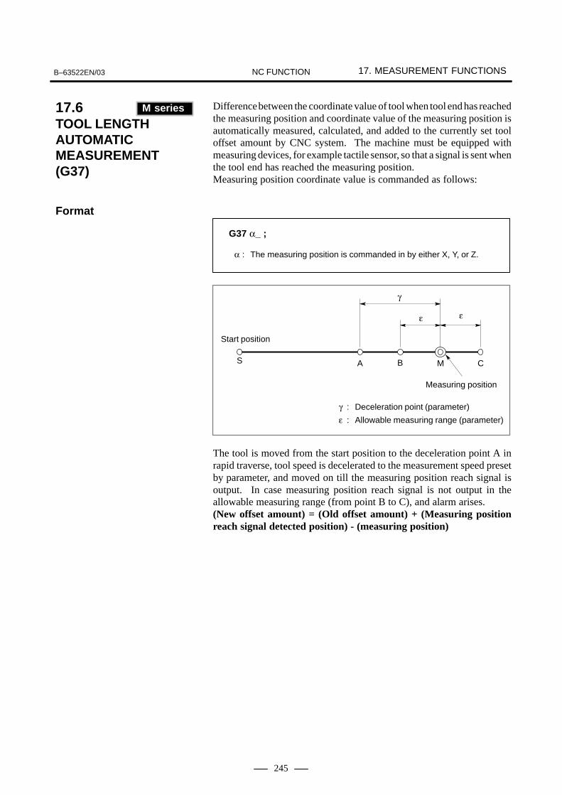
B–63522EN/03 17. MEASUREMENT FUNCTIONSNC FUNCTION
245
Difference between the coordinate value of tool when tool end has reachedthe measuring position and coordinate value of the measuring position isautomatically measured, calculated, and added to the currently set tooloffset amount by CNC system. The machine must be equipped withmeasuring devices, for example tactile sensor, so that a signal is sent whenthe tool end has reached the measuring position. Measuring position coordinate value is commanded as follows:
G37 α_ ;
α : The measuring position is commanded in by either X, Y, or Z.
A B MS C
γ
ε ε
γ : Deceleration point (parameter)
ε : Allowable measuring range (parameter)
Start position
Measuring position
The tool is moved from the start position to the deceleration point A inrapid traverse, tool speed is decelerated to the measurement speed presetby parameter, and moved on till the measuring position reach signal isoutput. In case measuring position reach signal is not output in theallowable measuring range (from point B to C), and alarm arises.(New offset amount) = (Old offset amount) + (Measuring positionreach signal detected position) - (measuring position)
17.6TOOL LENGTH AUTOMATICMEASUREMENT(G37) (M series)
M series
Format

17. MEASUREMENT FUNCTIONS B–63522EN/03NC FUNCTION
246
Difference between the coordinate value of tool when tool end has reachedthe measuring position and coordinate value of the measuring position isautomatically measured, calculated, and added to the currently set tooloffset amount by CNC system. The machine must be equipped withmeasuring devices, for example tactile sensor, so that a signal is sent whenthe tool end has reached the measuring position. Measuring position coordinate value is commanded as follows:
G36 X_ ;
G37 Z_ ;or
A B MS C
γ
ε ε
γ : Deceleration point (parameter)
ε : Allowable measuring range (parameter)
Start position
Measuring position
The tool is moved from the start position to the deceleration point A inrapid traverse, tool speed is decelerated to the measurement speed presetby parameter, and moved on till the measuring position reach signal isoutput. In case measuring position reach signal is not output in theallowable measuring range (from point B to C), and alarm arises.(New offset amount) = (Old offset amount) + (Measuring positionreach signal detected position) - (measuring position)
17.7AUTOMATIC TOOL OFFSET (G37, G36)(T series)
T series
Format

B–63522EN/03 17. MEASUREMENT FUNCTIONSNC FUNCTION
247
The value displayed as a relative position can be set in the offset memoryas an offset value by a soft key.Call offset value display screen. Relative positions are also displayed onthis screen. Reset the displayed relative position to zero. Set the tool formeasurement at the same fixed point on the machine by hand. The relativeposition display at this point shows difference between the reference tooland the tool measured and the relative position display value is then setas offset amounts.
Reference toolThis difference is setas offset amount
ÇÇÇÇÇÇÇÇ
ÇÇÇÇÇÇ
Fixed point
17.8TOOL LENGTH MEASUREMENT(M series)
M series

17. MEASUREMENT FUNCTIONS B–63522EN/03NC FUNCTION
248
This is a function of setting an offset value by key-inputting a workpiecediameter manually cut and measured from the MDI keyboard. First the workpiece is cut in the longitudinal or in the cross directionmanually. When a button on the machine operator’s panel is pressed uponcompletion of the cutting, the workpiece coordinate value at that time isrecorded. Then, withdraw the tool, stop the spindle, and measure thediameter if the cutting was on the longitudinal direction or distance fromthe standard face if it was on the facing. (The standard face is made as Z= 0.) When the measured value is entered into the offset number desiredplus 100, NC inputs the difference between the input measured value andthe coordinate value recorded in NC, as the offset value of the offsetnumber.The workpiece coordinate system can be shifted using the technique ofdirectly inputting the measured value for offset. This technique is usedwhen the coordinate system planned in the program does not match withthe coordinate system set by the G92 command or by the automaticcoordinate system setting.The procedures are the same as those for direct input for offset, except adifference of using the standard tool.
ÇÇÇÇÇÇÇÇÇÇÇÇ
x X
z
Zα
β
O
O’
B face
A face
X-Z:Coordinate system planned in the programx-z : Coordinate set actually
Reference pointplanned in the program
Cut A or B face and measure β or α. Direct input the measured value.
17.9DIRECT INPUT OF TOOLCOMPENSATIONMEASURED VALUE/ DIRECT INPUT OF WORKPIECECOORDINATESYSTEM SHIFT AMOUNT (T series)
T series

B–63522EN/03 17. MEASUREMENT FUNCTIONSNC FUNCTION
249
By installing the touch sensor and by manually making the tool contactthe touch sensor, it is possible to set the offset amount of that toolautomatically in the tool offset amount memory. It is also possible to setthe workpiece coordinate system shift amount automatically.In addition, a tool setter function for one–turret two–spindle lathes isprovided so that the tool compensation value measured value direct inputB function can be used for both spindles of a one–turret two–spindle lathe.
As the touch sensor detection mode, either four–contact input mode orsingle–contact input mode can be selected.
1) Four–contact input (when bit 3 (TS1) of parameter No. 5004 is set to 0)The touch sensor has contact faces in two directions along each axis,and outputs four signals when a touch is detected. These signals areinput to the CNC as tool compensation value writing signals (+MIT1,+MIT2, –MIT1, and –MIT2). When any of these input signals is input, the CNC stops feed in thecorresponding direction along the corresponding axis.
2) Single–contact input (when bit 3 (TS1) of parameter No. 5004 is setto 1)The touch sensor outputs one signal when a touch by a single–contactinput is detected. This signal is input to the CNC as the toolcompensation value writing signal (+MIT1). Then, the CNC determines the two directions along each axisautomatically and stops feed in the corresponding direction along thecorresponding axis.
SignalParameter
Signal����� �����
+MIT1 Contact the (+) contact face of theX–axis (Contact in the X+ direction)
The two directionsalong each axis is de-termined automatically.
–MIT1 Contact the (–) contact face of theX–axis (Contact in the X– direction)
Not used
+MIT2 Contact the (+) contact face of theZ–axis (Contact in the Z+ direction)
Not used
–MIT2 Contact the (–) contact face of theZ–axis (Contact in the Z– direction)
Not used
17.10TOOLCOMPENSATION VALUE MEASURED VALUE DIRECT INPUTB (T series)
T series
Explanations
� Touch sensor

17. MEASUREMENT FUNCTIONS B–63522EN/03NC FUNCTION
250
+Z
+X
(–) contact face of X axis(–MITX)
(–) contact face of Z axis(–MITZ)
(+) contact face of X axis(+MITX)
(+) contact face of Z axis(+MITZ)
� Setting of tool compensation valuePreviously set the distance from the measurement reference position(a particular point on the machine) to the measuring position (the touchsensor contact face) to the parameter as the reference value. As the tool of which the offset amount is to be measured is selected andis positioned at the measuring position (contact the touch sensor), thecontact detection signal (tool compensation value write signal) fromthe touch sensor is received, and the difference between the machinecoordinate value at that time (= the distance from the measured toolnose tip position at the machine reference position (machine zeropoint) to the measuring position) and the reference value (parametervalue) is set in the tool offset amount memory as the tool geometryoffset amount of that tool. The corresponding tool wear offset amountbecomes zero.
Tool offset
amount to
be set
Machine coordi-nate value whentool compensa-tion value writesignal turns “1”
Reference value(value of parameter)corresponding totool compensationvalue write signal
= +
The tool offset amount to be set depends on how to determine themeasurement reference position.
� Setting method

B–63522EN/03 17. MEASUREMENT FUNCTIONSNC FUNCTION
251
Supplement : When single–contact input (when bit 3 (TS1) of parameterNo. 5004 is set to 1) is set for touch detection in the touch sensor
When receiving the touch detection signal (tool compensation valuewriting signal +MIT1) from the touch sensor, the CNC determines thetwo directions along each axis automatically according to the numberof pulses stored for the movement along each axis that has been madeuntil the input of the signal. (Set the number of interpolation cyclesof stored pulses in parameter No. 5021 in advance.)
After determining the two directions along each axis automatically,the CNC applies axis interlock to the corresponding axis direction tostop feed operation, and the calculated tool compensation value isstored in tool compensation memory.
When stored pulses show various directions, when the servo power isshut down (the servo off state), or when no pulse is stored because noaxis movement has taken place, the direction cannot be determined,so P/S alarm No. 5195 is generated.
Also when the tool moves along two axes (the X–axis and Z–axis), theP/S alarm is generated. So, the tool must be moved along just one axis.
If the P/S alarm is generated, the tool compensation value is not set,and the two axes and four directions are interlocked.
NOTE1 Pulses used for automatic determination are stored while
the tool compensation value writing mode select signalGOSQM <G039#7> is 1 in manual mode. These pulses arelost when:a. A mode other than manual mode is set.b. The tool compensation value writing mode select signal
GOSOM <G039#7> is driven to 0.c. The tool compensation value is set upon reception of the
touch detection signal from the touch sensor, or P/Salarm No. 5195 is generated.
d. The servo off state is entered. In this case, the pulsesstored for the axis for which the servo off state is enteredare lost.
e. Axis movement is performed. In this case, pulses storedfor the other axis along which no movement takes placeare lost.
2 Axis interlock applied in the axis direction determinedautomatically and two–axis four–direction interlock applieddue to a P/S alarm are released when a mode other thanmanual mode is set or when the tool compensation valuewriting mode select signal GOSQM <G039#7> is driven to0. This type of interlock is not released by a reset operation.

17. MEASUREMENT FUNCTIONS B–63522EN/03NC FUNCTION
252
� Setting of workpiece coordinate system shift amount The workpiece coordinate system shift amount along the Z axis is tobe set as follows. When the tool touches the end face of the workpiece,the touch detection signal (workpiece coordinate system shift writesignal) is output. This signal is used to set the workpiece coordinatesystem shift, calculated by subtracting the tool geometrycompensation value (shift of coordinate system due to tool geometrycompensation) from the current machine coordinate (distance betweenthe end face of the workpiece and the tip of the measurement tool whenit is at the machine reference position (machine zero point)). In thiscase the tool geometry offset amount corresponding to the tool mustbe programmed previously.
Machine
coordinate value
of Z axis (Zt)
Workpiece coordinate
system shift amount
along Z axis to be
set (EXOFSz)
Tool geometry offset
amount of Z axis of
corresponding tool
(OFSz)
= +
By the above procedure the workpiece coordinate system with theworkpiece edge (sensor contact point) being taken as the workpiececoordinate system zero point of the Z axis (the program zero point) is setwhen the tool is selected by the program command (T code).
–EXOFSZ
OFSZ
Zt
OFSX
+X
+Z
Machinezero point
EXOFSz : Workpiece coordinate system shift amount to be set
OFSz : Tool geometry offset amount
Zt : Machine coordinate value (Distance to workpiece edge)
Workpiece coordinatesystem zero point(Program zero point)
Measured toolnose positionat machine ref-erence position
B–63522EN/03 17. MEASUREMENT FUNCTIONSNC FUNCTION
253
By manipulating soft keys, a position value displayed on the relativeposition display can be set to the offset memory.Call offset value display screen on the screen. Relative positions are alsodisplayed on this screen. Reset the displayed relative position to zero.Set the tool for measurement at the same fixed point on the machine byhand. The relative position display at this point shows difference betweenthe reference tool and the tool measured and the relative position displayvalue is then set as offset amounts.
By directly entering the measured deviation of the actual coordinatesystem from a programmed workpiece coordinate system, the workpiecezero point offset at the cursor is automatically set so that a command valuematches the actual measurement.
To enable measurement of the tool length, the following functions aresupported: automatic measurement of the tool length by using a programcommand (G37) (automatic tool length measurement, described inSection 17.6) and measurement of the tool length by manually moving thetool until it touches a reference position, such as the workpiece top surface(tool length measurement, described in Section 17.8). In addition to thesefunctions, tool length/workpiece origin measurement B is supported tosimplify the tool length measurement procedure, thus facilitating andreducing the time required for machining setup. This function alsofacilitates the measurement of the workpiece origin offsets.
This function allows the operator to specify T/M code commands orreference position return, by means of a manual numeric command, whilethe tool length offset measurement screen is displayed.
17.11COUNT INPUT OF TOOL OFFSET VALUES (T series)
T series
17.12DIRECT INPUT OF WORKPIECE ZERO POINT OFFSET VALUE MEASURED
17.13TOOL LENGTH/WORKPIECE ORIGINMEASUREMENT B (Mseries)
M series

18. CUSTOM MACRO B–63522EN/03NC FUNCTION
254
18 CUSTOM MACRO
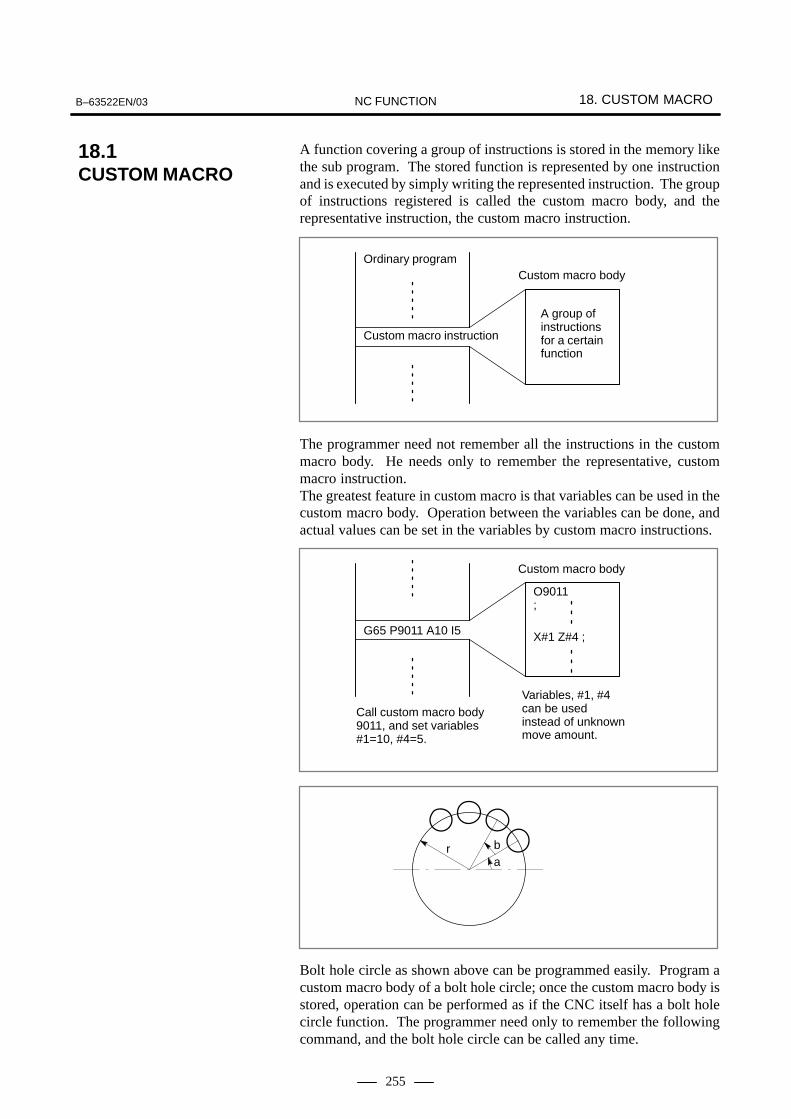
B–63522EN/03 18. CUSTOM MACRONC FUNCTION
255
A function covering a group of instructions is stored in the memory likethe sub program. The stored function is represented by one instructionand is executed by simply writing the represented instruction. The groupof instructions registered is called the custom macro body, and therepresentative instruction, the custom macro instruction.
Custom macro instruction
Custom macro body
A group ofinstructionsfor a certainfunction
Ordinary program
The programmer need not remember all the instructions in the custommacro body. He needs only to remember the representative, custommacro instruction.The greatest feature in custom macro is that variables can be used in thecustom macro body. Operation between the variables can be done, andactual values can be set in the variables by custom macro instructions.
G65 P9011 A10 I5
O9011;
X#1 Z#4 ;
Call custom macro body9011, and set variables#1=10, #4=5.
Variables, #1, #4can be usedinstead of unknownmove amount.
Custom macro body
r ba
Bolt hole circle as shown above can be programmed easily. Program acustom macro body of a bolt hole circle; once the custom macro body isstored, operation can be performed as if the CNC itself has a bolt holecircle function. The programmer need only to remember the followingcommand, and the bolt hole circle can be called any time.
18.1CUSTOM MACRO

18. CUSTOM MACRO B–63522EN/03NC FUNCTION
256
G65 Pp Rr Aa Bb Kk ;
p : Macro number of the bolt hole circle
r : Radius
a : Initial angle
b : Angle between holes
k : Number of holes
With this function, the CNC can be graded up by the user himself. Custommacro bodies may be offered to the users by the machine tool builder, butthe users still can make custom macro himself.The following functions can be used for programming the custom macrobody.
Variables: #1 (i=1, 2, 3,.......) Quotation of variables: F#33 (#33: speed expressed by variables)
Various operation can be done between variables and constants.The following operands, and functions can be used:+ (sum), – (difference), * (product), / (quotient), OR (logical sum), XOR(exclusive logical sum), AND (logical product), SIN (sine), COS(cosine), TAN (tangent), ATAN (arc tangent), SQRT (square roots), ABS(absolute value), BIN (conversion from BCD to binary), BCD(conversion from binary to BCD), FIX (truncation below decimal point),FUP (raise fractions below decimal point), ROUND (round) Example : #5 = SIN [[#2 + #4] � 3.14 + #4] � ABS (#10)
Program flow in the custom macro body is controlled by the followingcommand.
� If [<conditional expression>]GOTO n (n = sequence number) When <conditional expression> is satisfied, the next execution is donefrom block with sequence number n.When <conditional expression> is not satisfied, the next block isexecuted. When the [<IF conditional expression>] is committed, it executesfrom block with n unconditionally.The following <conditional expressions> are available:
#j EQ #k whether #j = #k#j NE #k whether #j = #k#j GT #k whether #j > #k#j LT #k whether #j < #k#j GE #k whether #j � #k #j LE #k whether #j � #k
� IF[<conditional expression>]THENIf the specified conditional expression is satisfied, a predeterminedmacro statement is executed. Only a single macro statement isexecuted.
Format
Explanations
� Use of Variable
� Operation betweenvariables
� Control command
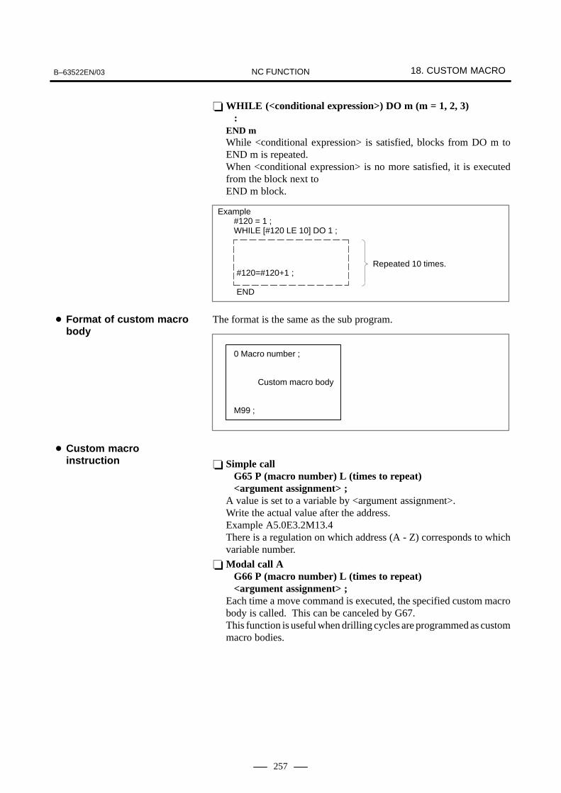
B–63522EN/03 18. CUSTOM MACRONC FUNCTION
257
� WHILE (<conditional expression>) DO m (m = 1, 2, 3) :END m While <conditional expression> is satisfied, blocks from DO m toEND m is repeated.When <conditional expression> is no more satisfied, it is executedfrom the block next to END m block.
Example#120 = 1 ;WHILE [#120 LE 10] DO 1 ;
#120=#120+1 ;
END
Repeated 10 times.
The format is the same as the sub program.
0 Macro number ;
Custom macro body
M99 ;
� Simple callG65 P (macro number) L (times to repeat) <argument assignment> ;
A value is set to a variable by <argument assignment>.Write the actual value after the address. Example A5.0E3.2M13.4 There is a regulation on which address (A - Z) corresponds to whichvariable number.
� Modal call AG66 P (macro number) L (times to repeat) <argument assignment> ;
Each time a move command is executed, the specified custom macrobody is called. This can be canceled by G67. This function is useful when drilling cycles are programmed as custommacro bodies.
� Format of custom macrobody
� Custom macroinstruction
18. CUSTOM MACRO B–63522EN/03NC FUNCTION
258
� Macro call by G codesThe macro can also be called by the parameter-set G codes. Insteadof commanding:
N_ G65 P���� <argument assignment> ;macro can be called just by commanding:
N_ Gxx <argument assignment> ;.G code for calling the macro, and macro program number **** to becalled, are coupled together and set as parameter.Maximum ten G codes from G01 to G9999 can be used for macro call(G00 cannot be used). The G code macro call cannot be used in the macro which was calledby a G code. It also cannot be used in sub programs called by subprogram call with M codes or T codes.
� Macro call by M codeCustom macros can be called by pre-determined M codes which areset by parameters.The following command
N_ G65 P���� <Argument assignment> ;is equivalent to the following command:
N_ Mxx <Argument assignment> ;The correspondence between M codes (Mxx) and program number(delta delta delta delta) of a macro shall be set by a parameter. Signal MF and M code are not sent out the same as the subprogram callby M code. Also when this M code is specified in a program called a macro callingG code or a subprogram calling M or T code, the M code is regardedas a normal M code. Up to ten M codes from M01 to M99999999 can be used for custommacro calling M codes.
� Sub program call by M codeAn M code can be set by parameter to call a sub program. Instead ofcommanding:
N_ G_ X_ Y_ … M98 P���� ; ,the same operation can be performed simply by commanding:
N_ G_ X_ Y_ … Mxx ;.As for M98, M codes are not transmitted.The M code XX for calling the sub program and the sub programnumber delta delta delta delta to be called are coupled together and setby parameter. Maximum ten M codes from M01 to M99999999 can be used formacro call. Arguments cannot be transmitted. It also cannot be commanded in thesame block as the block with M98 command. When these M codes are commanded in macro called by G code or insubprogram called by M code or T code, they are regarded as ordinaryM codes.

B–63522EN/03 18. CUSTOM MACRONC FUNCTION
259
� Sub program call by T codeBy setting parameter, sub program can be called by T codes. Whencommanded:
N_ G_ X_ Y_ … Tt ; ,the same operation is done as when commanded: #149 = t;
N_ G_ X_ Y_ … M98 P9000; .The T type code t is stored as arguments of common variable #149. This command cannot be done in the same block with a sub programcalling M code, or with M98 command. The T code is not output. When T code is commanded in macros called by G code, or in subprograms called by M codes or T codes, the T code is treated asordinary T codes.
Variables are divided into local variables, common variables, and systemvariables, according to their variable numbers. Each type has different useand nature.
� Local variables #1 – #33Local variables are variables used locally in the macro. Accordingly,in case of multiples calls (calling macro B from macro A), the localvariable used in macro A is never destroyed by being used in macroB.
� Common variables #100 – #149, #500 – #531Compared with local variables used locally in a macro, commonvariables are common throughout the main program, each subprogram called from the main program, and each macro. The commonvariable #1 used in a certain macro is the same as the common variable#i used in other macros. Therefore, a common variable #1 calculatedin a macro can be used in any other macros. Common variables #100 to #149 are cleared when power is turned off,but common variables #500 to #531 are not cleared after power isturned off.
NOTEThe range of common variables can be enlarged to #100 to#199, and #500 to #999 by the option. (See SectionII–18.2.)
� System variablesA variable with a certain variable number has a certain value. If thevariable number is changed, the certain value is also changed.The certain value are the following:
� 16 points DI (for read only)� 48 points DO (for output only)� Tool offset amount, work zero point offset amount� Position information (actual position, skip position, block end
position, etc.)� Modal information (F code, G code for each group, etc.)� Alarm message (Set alarm number and alarm message, and the
CNC is set in an alarm status. The alarm number and message isdisplayed.)
� Types of variables

18. CUSTOM MACRO B–63522EN/03NC FUNCTION
260
� A date (year, month, day) and time (hour, minute, second) areindicated.
� Clock (Time can be known. A time can also be preset.)
� Single block stop, Miscellaneous function end wait hold
� Feed hold, Feed rate override, Exact stop inhibition
�The number of machining parts is indicated. It can be preset.
Value of variables or characters can be output to external devices via thereader/puncher interface with custom macro command. Results inmeasurement is output using custom macro.
� Usable variablesSee “Types of variables”.
� Usable variable valuesMaximum : ±1047 Minimum : ±10-29
� Constants usable in <expression>Maximum : ±99999999 Minimum : ±0.0000001Decimal point allowed
� Arithmetic precision8-digit decimal number
� Macro call nestingMaximum 4 folds.
� Repeated ID numbers 1 - 3
� ( ) nestingMaximum 5 folds.
� Sub program call nesting8 folds (including macro call nesting)
� External outputcommands
� Limitations
B–63522EN/03 18. CUSTOM MACRONC FUNCTION
261
The range of common variables can be enlarged to #100 to #199, and #500to #999 by the option.
When custom macro interruption signal is input during automaticoperation, the block currently under execution is interrupted and thespecified custom macro is activated. After execution of this custommacro, it returns to the interrupted block and continues execution of theremaining commands.
:M96P_ ;
: When custom macro interruption signal is input between M96 blockand M97 block, custom macro specified by P is activated.
M97;:
This function enables implementation of an application of detecting abroken tool, entering a custom macro interrupt signal, executing a toolchange cycle using the custom macro, and then restarting machining afterthe tool change.
18.2INCREASED CUSTOMMACRO COMMON VARIABLES
18.3INTERRUPTION TYPECUSTOM MACRO

18. CUSTOM MACRO B–63522EN/03NC FUNCTION
262
With this function, custom macro interruption signal can be input ondetection of tool break, tool change cycle can be executed by custommacro, and machining is continued. This function simplifies program creation for CNC machining. Instead ofprogramming in the NC format, the program can be created by selectinga menu and entering data according to the menu displayed on the CRTscreen. A menu is provided for each type of drilling such as boring andtapping. A programmer can select data necessary for actual machiningfrom these menus. Machining data such as hole position and hole depthis also provided in menus. The programmer can create a program simplyby entering data from the menus.This function is basically executed by the custom macro created by amachine tool builder. What menus and machining data to prepare totallydepends on a machine tool builder. Therefore, a machine tool builder canincorporate their own know-how into this function.
MENU:HOLE PATTERN O9505 N0001
1. TAPPING 2. DRILLING 3. BORING 4. POCKET 5. BOLT HOLE 6. LINEANGLE 7. GRID 8. PECK 9. 10.
>_ S 0 T0000EDIT **** *** *** 15:56:32[ MACRO ][ MENU ][ OPR ][ ][(OPRT) ]
Pattern menu display
VAR. : BOLT HOLE O9505 N0001 NO. NAME DATA COMMENT 500 TOOL 0.000 501 KIJUN X 0.000 *BOLT HOLE 502 KIJUN Y 0.000 CIRCLE* 503 RADIUS 0.000 SET PATTERN 504 S. ANGL 0.000 DATA TO VAR. 505 HOLES NO. 0.000 NO.500–505. 506 0.000 507 0.000ACTUAL POSITION (RELATIVE) X 0.000 Y 0.000 Z 0.000 >_ S 0 T0000 MDI **** *** *** 15:56:32[OFFSET ][SETING ][ ][ ][(OPRT) ]
5 is selected
Pattern data display
18.4PATTERN DATA INPUT

B–63522EN/03 18. CUSTOM MACRONC FUNCTION
263
There are two types of NC programs; those which, once created, arescarcely changed, and those which are changed for each machining type.The former are programs created by the custom macro, and the latter aremachining programs. If programs of these types are executedsimultaneously, a battery may run out or the custom macro may bedestroyed by error operation.Such problems can be solved by this function. The custom macro createdby a machine tool builder is converted to an execute-form program, becataloged in the Flash ROM module, and be executed.
� Since the program is cataloged after converted to an execute-formprogram, the execution speed is high. The machining time is thenreduced, and the precision is improved.
� Since the program is cataloged in Flash ROM, there is no problem ofbattery extinction or custom macro destruction by error operation. Thereliability is improved.
� Since the cataloged program is not displayed on a program screen, theknow-how of the machine tool builder is protected.
� Since the custom macro is cataloged in Flash ROM, the program editmemory can be used efficiently.
� The user can call the macro easily without knowing the catalogedprogram. A custom macro can be created and executed in the programedit memory as usual.
� An original screen can be created by using the graphic display orselecting screens by the soft key. The machine tool builder can extendthe control function by using such functions as machining programcreation and edit control, reader/punch interface control, and PMCdata read/write functions.
NOTE1 When the macro executor is attached, the order-made
macro cannot be specified.
2 To use the macro executor function for graphics display, theoption for the graphics function is required.
18.5MACRO EXECUTER FUNCTION
Features

18. CUSTOM MACRO B–63522EN/03NC FUNCTION
264
As with the conversational macro function of macro executors/compilers,the C language executor function is used to customize screens and includeunique operations. Application programs for display and operation canbe created in standard C language, in the same way as programs are madefor normal personal computers. A program compiled on a personalcomputer is transferred and stored in flash ROM in the CNC via a memorycard. The program is read into memory upon activation of the CNC, andexecuted by the C language executor.
No special additional hardware is needed to run the C language executorand application programs (*). All available display units are supported.User applications can be included in the current CNC system.
NOTE(*) : The flash ROM/DRAM capacity may have to be increased.
Application programs can be developed using an ordinary personalcomputer. Program development, from program creation and editing tocompilation/linkage, can also be performed on a personal computer. And,to a certain extent, debugging is also possible on the personal computer.
Microsoft Corporation’s C compiler (MS–C) is employed as the Clanguage compiler. It is the de–facto standard C compiler for personalcomputers. The function library provided by the C language executor hasexcellent compatibility with the ANSI standards and MS–C. Therefore,application programs for ordinary personal computers can be transportedto the CNC, except when they are dependent on particular hardware.
An application program created by the machine tool builder is executedas one task of the CNC software. The application program can displayits own screens in place of existing CNC screens. In addition, theapplication program can read and write CNC system data via librariesprovided by the C language executor. This enables operation of theapplication program to be integrated with CNC software.
The C language executor can be used with the macro executor. Not onlyexecutable macros, but also conversational macros can be used together.The screen display portion of a macro program already created by themachine tool builder can be replaced with a program coded in C. This canprevent existing software resources from becoming useless.
18.6C LANGUAGE EXECUTERFUNCTION
Features
� Low–cost customization
� Application developmenton a personal computer
� High compatibility with Clanguage applicationprograms for personalcomputers
� Integration of CNCsoftware andapplications
� Using the C languageexecutor with the macroexecutor

B–63522EN/03 18. CUSTOM MACRONC FUNCTION
265
Macro programs created by the machine tool builder are stored in FROM.The macro programs stored in FROM are loaded into DRAM at power–upso that they can be called from CNC programs stored in ordinary partprogram storage (SRAM). These macro programs can be edited in thesame way as ordinary CNC programs. An edited macro program can bestored in FROM.An arbitrary password can be used to disable macro program editing.This function stores the machine tool builder’s macro programs in an areaseparate from part program memory, so the machine tool builder cancreate macro programs without reducing the user program capacity.(Macro programs as large as 225–m paper tape storage size can be stored.)In addition, this function stores macro programs in FROM, so they cannotbe erased easily by mistake.
The BOOT system allows I/O of embedded macro file INMC fromFROM to a memory card.
Embedded macro program numbers are determined by setting thebeginning program number in parameter No. 12011 and the end programnumber in parameter No. 12012. Program numbers beyond this range areassigned to user programs stored in part program storage.
Embedded macro programs can be edited in the same way as programsstored in part program storage. After edited, a macro program can bewritten (stored) into FROM to make the program available when thepower is turned on again.Edited macro programs can be input/output to external devices throughan interface such as the reader/punch interface.
Embedded macro programs in DRAM can be written into FROM. Macroprograms in DRAM are stored in FROM at a time under the file nameINMC.
When a new FROM file INMC for embedded macros is created, apassword can be given to the INMC file by setting a value from–99999999 to 99999999 (the password) in parameter No. 12013 andstoring (saving) a macro program in FROM. If the password is set to 0,no password is assumed, and the file is left unlocked.To unlock the file, enter the password in parameter No. 12013.When the file is in the unlocked state, an embedded macro program canbe stored in FROM. The items 1 to 5 listed below follow parametersettings in the CNC.To lock the file, enter a non–password value in parameter No. 12013.When the file is locked, no embedded macro program can be stored. Theitems 1 to 5 listed below follow the parameter–set data stored in FROM.
1. Embedded macro program overwrite enabled/disabled (bit 0 ofparameter No. 12001)
2. Embedded macro program reference and editing enabled/disabled(parameter No. 12010)
3. Embedded macro program number (parameter Nos. 12011 and 12012)4. Embedded macro series and edition (parameter Nos. 12015 and
12016)5. Embedded macro G codes and corresponding program numbers
(parameter Nos. 12020 to 12049)
18.7EMBEDDED MACROS
Explanations
� Program number
� Editing embedded macroprograms
� Write (storage) fromDRAM to FROM
� Embedded macro key(keyword, password)

18. CUSTOM MACRO B–63522EN/03NC FUNCTION
266
The INMC file in FROM is loaded into the embedded macro DRAM areaat power–up.
The BOOT system allows I/O of embedded macro file INMC fromFROM to a memory card.
A G code is used to call an embedded macro program. The relationshipsbetween G codes and the numbers of called embedded macro programsare set in parameters. Up to 10 pairs can be set. Embedded macroprograms can also be called using a macro call by G65 or G66 and asub–program call by M98.
Common variables #200 to #499 can be used.
Created embedded macro files can be managed with series and editions.The series and edition of the embedded macro file currently used areindicated to the right of ”EMBED MCR” on the system configurationscreen.
� Read from FROM toDRAM (loading)
� I/O from FROM
� Embedded–macro call
� Common variables #200to #499
� Series and edition

B–63522EN/03 18. CUSTOM MACRONC FUNCTION
267
When this function is incorporated into the embedded macro function,four types of machining cycles (drilling, facing, side facing, andpocketing) can be used easily. For use of this function, the embeddedmacro, canned cycle, and custom macro B options are required.
NOTEThis function and the manual guide function cannot bespecified at the same time. A function equivalent to thisfunction is included in the manual guide.
When this function is incorporated into the embedded macro function,two types of measurement cycles (a calibration cycle and measurementcycle) can be used easily. The calibration cycle measures compensationdata for a probe that is a measuring device, and the measurement cycleperforms measurement by using this compensation data.There are two types of measurement cycles as follows:
– Centering measurement cycle: Measures coordinates that are to beused as the reference position of the workpiece, and sets that data inthe workpiece coordinate system.
– Internal measurement cycle: Measures the dimensions andcoordinates of a machined workpiece and sets them in appropriatevariables.
NOTEThis function and the manual guide function cannot bespecified at the same time. A function equivalent to thisfunction is included in the manual guide.
18.8EMBEDDED MILLINGMACRO (M series)
M series
18.9MEASUREMENTCYCLE (M series)
M series

19. SERIES 15 TAPE FORMAT/SERIES 10/11 TAPE FORMAT B–63522EN/03NC FUNCTION
268
19 SERIES 15 TAPE FORMAT/SERIES 10/11 TAPEFORMAT

19. SERIES 15 TAPE FORMAT/ SERIES 10/11 TAPE FORMATB–63522EN/03 NC FUNCTION
269
The programs for the following functions can be created in the Series10/11 tape format, and be executed by the setting parameter, using thememory.
� Equal lead threading (G33) (T series): (G32 for G-code system A)
� Sub program calling (M98)
� Canned cycles (G77, G78, G79) (T series):(G90, G92, G94 for G-code system A)
� Multiple repetitive canned cycles (G71 to G76) (T series)
� Canned cycles for drilling (G80 to G85) (T series)
� Canned cycles (G73, G74, G76, G80 to G89) (M series)
NOTEAddresses and range of values to be specified the Series16/18 format restrictions are placed on the range ofspecifiable values of the basic address. Specifying a valueoutside the Series 16/18 format range causes a P/S alarm.The restrictions are placed also on some addresses.
Memory operation of a program created for the following function in theSeries 10/11 tape format can be performed based on the setting parameter.
� Equal–lead threading (G33) (T series) ... (G32 with G code system A)
� Subprogram call (M98)
� Canned cycle (G77, G78, G79) (T series) ... (G90, G92, and G94 withG code system A)
� Multiple repetitive canned cycle (G71 to G76) (T series)
� Canned cycle for drilling (G80 to G85) (T series)
� Canned cycle (G73, G74, G76, G80 to G89) (M series)
NOTEAddress and value specification rangeThe restrictions imposed on the Series 21 format are alsoimposed on the value specification range for the basicaddresses. When a specified value exceeds the range ofthe Series 21 format, a P/S alarm is issued. The use ofaddresses may be restricted in some cases.
19.1SERIES 15 TAPE FORMAT
19.2SERIES–10/11 TAPE FORMAT

20. FUNCTIONS FOR HIGH SPEED CUTTING B–63522EN/03NC FUNCTION
270
20 FUNCTIONS FOR HIGH SPEED CUTTIN

20. FUNCTIONS FOR HIGH SPEED CUTTINGB–63522EN/03 NC FUNCTION
271
This function converts the profile to be machined into data for high-speedpulse distribution, using the macro compiler or macro executor. It thencalls and executes the data with the CNC command (G05) as a machiningcycle.Up to six axes can be commanded. (Up to six axes can be controlledsimultaneously.)The following command calls and executes the high-speed cyclemachining data specified by the macro compiler or micro executor.
G05 P10��� L��� ;
P10001 to P10999 : Starting number of the machining cycle to be called
L1 to L999 : Number of machining cycle repeats (The default value is L1.)
Up to 999-cycle data can be created. Address P specifies the cycle formachining. Two or more cycles can be called and executed successivelyaccording to the connection information (in the header). Address Lspecifies the number of times that the machining cycle is repeated. Thenumber of repeats (in the header) can be specified for each cycle.The following example explains the cycle connection and number ofrepeats.
Example)G05 P10001 L2 is specified for the following cycles:Cycle 1, connection 2, number of repeats 1Cycle 2, connection 3, number of repeats 3Cycle 3, connection 0, number of repeats 1The cycles of 1,2,2,2,3,1,2,2,2,3 are executed successively.
20.1HIGH–SPEED CYCLE MACHINING (ONLY AT1–PATH CONTROL)
20.1.1High–speed Cycle Machining (only atone–path)
Format

20. FUNCTIONS FOR HIGH SPEED CUTTING B–63522EN/03NC FUNCTION
272
This function cancels a repeated cycle operation of high–speed cyclemachining and skips to the header information connected next. Note that,however, a skip does not takes place at a halfway point of cycle operation.
Example)G05P10001L3 ;Cycle 1, connection information 2, number of repeats 1Cycle 2, connection information 3, number of repeats 2Cycle 3, connection information 4, number of repeats 3Cycle 4, connection information 0, number of repeats 1The cycles are executed as follows:
⇒ Normal cycle operation
1 , 2 , 2 , 3 , 3 , 3 , 4 ,1 , 2 , 2 , 3 , 3 , 3 , 4 , 1 , 2 , 2 , 3 , 3 , 3 , 4 ,
First Second Third
X Skip signal ��������
1 , 2 , 2 , 3 , 3 , 3 , 4 , 1 , 2 , 2 , 3 , 4 , Skip operation
First Second
20.1.2High–Speed CycleMachining SkipFunction

20. FUNCTIONS FOR HIGH SPEED CUTTINGB–63522EN/03 NC FUNCTION
273
This function automatically decelerates the tool at a corner according tothe corner angle. It can prevent a large sag caused by acceleration/deceleration and servo delay on the junction of two blocks.If the angle made by two consecutive blocks is less than the angle set bythe parameter in the cutting mode (G64) (M series), the speed isautomatically reduced at the end of the block. When the speed is reducedto the value set by the parameter or lower, movement of the next blockstarts.
ÇÇÇÇÇÇÇÇÇÇÇÇÇÇÇÇÇÇ
t
+Y
+X
Speed set by parameter
Block B
Block A
Speed
Y axisX axis
Time
20.2AUTOMATIC CORNERDECELERATION

20. FUNCTIONS FOR HIGH SPEED CUTTING B–63522EN/03NC FUNCTION
274
The machine is accelerated/decelerated automatically when themovement is started/stopped, so that the machine system should not beapplied with any shock. When programming, therefore, no considerationneeds to be made for acceleration/deceleration. Especially when performing the high-speed arc cutting, however, theactual tool passage may bring about some error against the designated arcduring circular interpolation due to this automatic acceleration/deceleration.This error can approximately be given by the following formula;
Command path
Actual path
�r � 12
(T12� T2
2) V2
r
r
Y
X
∆r : Maximum value of radius error (mm)v : Feedrate (mm/sec)
r : Circular radius (mm)
T1 : Exponential Acceleration/deceleration time constant at cutting (sec)
T2 : Time constant of servo motor (sec)
(1). . . . . . .
∆r
When performing the actual machining, the actual arc machining radius(r) and tolerance (∆r) are given, therefore, the maximum permissiblespeed v (mm/min.) can be given by the formula-(1).”Feedrate clamp by circular radius” is such function that the circularcutting feed is automatically clamped when the feedrate designated mayexceed the permissible tolerance to radial direction against the circular archaving optional radius designated by the program.
20.3FEEDRATE CLAMP BY CIRCULAR RADIUS (M series)
M series

20. FUNCTIONS FOR HIGH SPEED CUTTINGB–63522EN/03 NC FUNCTION
275
This function is designed for high–speed precise machining. With thisfunction, the delay due to acceleration/deceleration and the delay in theservo system which increase as the feedrate becomes higher can besuppressed.The tool can then follow specified values accurately and errors in themachining profile can be reduced.This function becomes effective when advanced preview control mode isentered.
G08 P_ ;
P1 : Turn on advanced preview control mode.
P0 : Turn off advanced preview control mode.
In advanced preview control mode, the following functions are available :� Linear acceleration/deceleration before interpolation� Automatic corner deceleration function
20.4ADVANCED PREVIEWCONTROL (G08)
Format

20. FUNCTIONS FOR HIGH SPEED CUTTING B–63522EN/03NC FUNCTION
276
When the remote buffer is connected to the host computer or input/outputdevice via serial interface, a great amount of data can be sent to CNCconsecutively at a high speed.
CNC
RS–232C / RS–422Remotebuffer
Hostcomputer
Input/outputdevice
The remote buffer enables the following operations:
� When connected to the host computer online, it performs DNCoperation with high reliability and at a high speed.
� The CNC program and parameters can be down-loaded from the hostcomputer.
� When connected to an input/output device, it enables DNC operation,and various data can be down-loaded. The following input/outputdevices can be connected.� FANUC PPR� FANUC FA Card� FANUC FLOPPY CASSETTE� FANUC PROGRAM FILE Mate� FANUC Handy File
� Electrical interfaceThe following two types of interface are prepared as standardspecifications.� RS-232C Interface� RS-422 Interface
RS-233C RS-422
InterfaceSerial voltage interface (start-stop)
Balanced transmission serialinterface (start-stop)
Baud rate 50 to 19,200 BPS 50 to 86,400 BPS (*1)
Cablelength
4800 BPS or less9600 BPSVaries according to I/O device.
Approx. 800 m (9600 BPS orless)19,200 BPS or more
20.5REMOTE BUFFER
20.5.1Remote Buffer (Only at1–path Control)
Explanations
� Interface between theremote buffer and hostcomputer

20. FUNCTIONS FOR HIGH SPEED CUTTINGB–63522EN/03 NC FUNCTION
277
The following three protocols are prepared as the communicationprotocols between the remote buffer and host computer. The protocol canbe selected by a parameter according to the specifications of the deviceto be connected.
Protocol Features Interface Maximumtransfer rate
Protocol A Handshake method. Sending andreceiving are repeated between two
RS-232C 19200 BPSreceiving are repeated between twostations. RS-422 86400 BPS
Extendedprotocol A
Similar to protocol A. Enables high-speed transfer of the NC program tomeet high-speed DNC operation.
RS-422 86400 BPS
Protocol B Controls communication with controlcodes output from the remote buffer.
RS-232C 19200 BPScodes output from the remote buffer.
RS-422 86400 BPS
NOTEThe average data transfer rate is lower than the maximumtransfer rate.
� Software interface
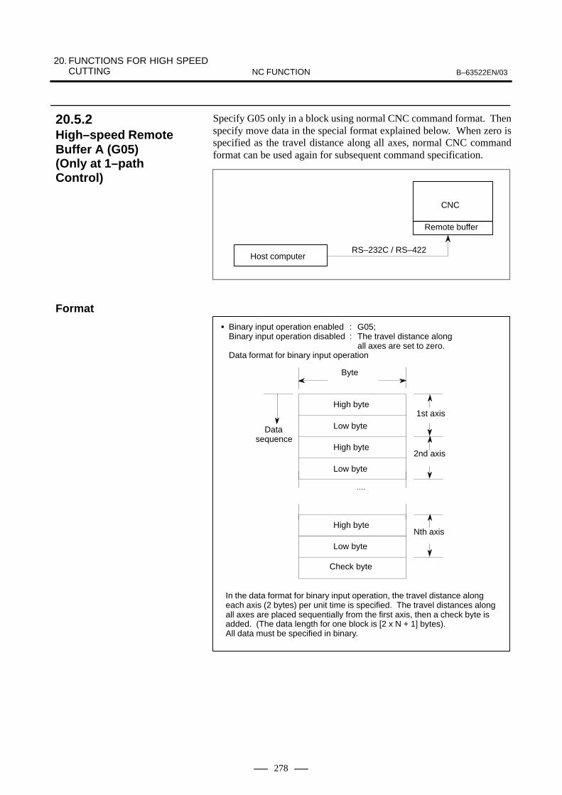
20. FUNCTIONS FOR HIGH SPEED CUTTING B–63522EN/03NC FUNCTION
278
Specify G05 only in a block using normal CNC command format. Thenspecify move data in the special format explained below. When zero isspecified as the travel distance along all axes, normal CNC commandformat can be used again for subsequent command specification.
Host computer
CNC
Remote buffer
RS–232C / RS–422
� Binary input operation enabled : G05;Binary input operation disabled : The travel distance along
all axes are set to zero.Data format for binary input operation
⋅⋅⋅⋅
Data sequence
1st axis
2nd axis
Nth axis
Check byte
Byte
High byte
High byte
High byte
Low byte
Low byte
Low byte
In the data format for binary input operation, the travel distance alongeach axis (2 bytes) per unit time is specified. The travel distances alongall axes are placed sequentially from the first axis, then a check byte isadded. (The data length for one block is [2 x N + 1] bytes).All data must be specified in binary.
20.5.2High–speed RemoteBuffer A (G05)(Only at 1–pathControl)
Format

20. FUNCTIONS FOR HIGH SPEED CUTTINGB–63522EN/03 NC FUNCTION
279
High–speed remote buffer A uses binary data. On the other hand,high–speed remote buffer B can directly use NC language coded withequipment such as an automatic programming unit to perform high–speedmachining.
G05 P01 ;
G05 P00 ;
Example) O1234 ; :G05P01 ; ⇐ Start high–speed machiningX_ Y_ Z_ ; :G05P00 ; ⇐ End high–speed machining :M02 ;
Start high–speed machining
End high–speed machining
20.5.3High–speed RemoteBuffer B (G05) (Only at 1–pathControl) (M series)
M series
Format

20. FUNCTIONS FOR HIGH SPEED CUTTING B–63522EN/03NC FUNCTION
280
Machining errors by CNC include those caused by acceleration/deceleration after interpolation. To prevent such errors, the RISCprocessor provides the following functions:
� Acceleration/deceleration before interpolation by pre-readingmultiple blocks. Because executed before interpolation,acceleration/deceleration does not cause a machining error.
� Automatic velocity control by smooth acceleration/deceleration. Bypre-reading multiple blocks, changes in the profile and speed, and theallowable acceleration of the machine can be taken into considerationto execute smooth acceleration/deceleration.
Smooth acceleration/deceleration increases the feed-forward coefficient.As a result, the tracking error of the servo system can be reduced.
When cutting feed per minute is specified, tens of blocks are pre-read. Thelinear acceleration/deceleration is executed for the command speedbefore interpolation.If acceleration/deceleration is executed after interpolation, theinterpolation data is changed. If it is executed for the feedrate before interpolation, the interpolation datais not affected.Since the interpolation data can always be placed on the specified line orcurve, there will be no machining profile error caused byacceleration/deceleration.
Linear acceleration/deceleration before interpolation
Feedrate calculation
Interpolationcalculation
Servocontrol
Velocitycom-mand
Distribu-tionpulse Acceleration/
deceleration after interpolation
Linear, exponentialfunction, bell type
Linear interpolation,circular interpolation,etc.
Linear bell type
A change in feedrates for each axis on the junction of two blocks (cornersection) may be greater than the value set in the parameter. In such a case,the appropriate feedrate (reduced speed) is calculated so that the changeis within the set value at the corner. The feedrate in the former blockautomatically reduces to the calculated value.
20.6HIGH–PRECISIONCONTOUR CONTROL(ONLY AT ONE–PATHCONTROL) (M series)
M series
20.6.1Acceleration/Decelera-tion Before Interpola-tion by Pre-readingMultiple Blocks

20. FUNCTIONS FOR HIGH SPEED CUTTINGB–63522EN/03 NC FUNCTION
281
This function pre-reads several blocks, and automatically controls thefeedrate.The feedrate is determined on the basis of the following items. If thecommand speed exceeds the feedrate, acceleration/deceleration beforeinterpolation is executed to reduce the speed.
� Change in speed for each axis at the corner, and allowable speedchange specified
� Acceleration expected for each axis, and allowable accelerationspecified
� Change in cutting load estimated by direction of Z-axis movement
In the automatic velocity control mode, acceleration/deceleration isexecuted before interpolation. The speed is then reduced automatically sothat the machine is not shocked much.Therefore, the time constant for automatic velocity control should bereduced, and the feed-forward coefficient should be increased. Themachining error caused by delay of acceleration/deceleration or the servosystem is then reduced.
20.6.2Automatic VelocityControl Function

20. FUNCTIONS FOR HIGH SPEED CUTTING B–63522EN/03NC FUNCTION
282
By taking full advantage of high–precision contour control using a RISCprocessor, this function enables high–speed high–precision machiningwithout the need for special hardware.
The function enables look–ahead linear acceleration/deceleration beforeinterpolation of up to 15 blocks. This results in smooth acceleration/deceleration over many blocks, as well as high–speed machining.
G05.1 Q_ ;
Q1 : Q0 :G05.1
Start AI contour control modeEnd AI contour control modeA block for specifying G05.1 must not contain any othercommand.AI contour control mode can also be canceled by a reset.
The high–speed linear interpolation function processes a move commandrelated to a controlled axis not by ordinary linear interpolation but byhigh–speed linear interpolation. The function enables the high–speedexecution of an NC program including a series of minute amounts oftravel.
��� �� � Start high–speed linear interpolation
��� �� � End high–speed linear interpolation
��� A block for specifying G05 must not contain any other command.
20.7AI CONTOURCONTROL (G05.1) (M series)
M series
Format
20.8HIGH–SPEED LINEARINTERPOLATION(G05) (M series)
M series
Format

20. FUNCTIONS FOR HIGH SPEED CUTTINGB–63522EN/03 NC FUNCTION
283
AI high–precision contour control is designed to enable high–speed,high–precision machining with programs that specify successive minuteline segments or NURBS curves like die machining. Use of this functionsuppresses the delay due to acceleration/deceleration and delay in theservo system that increase as the feedrate increases. This function,therefore, can have the tool follow specified values accurately and reduceerrors in machining profile, enabling high–speed, high–precisionmachining. Under AI high–precision contour control, acceleration/deceleration is performed more exactly than under conventionalhigh–precision contour control, so machining can speed up.AI nano high–precision contour control allows simultaneous use of nanointerpolation while providing all features of AI high–precision contourcontrol. The unit of output from the NC to servo system is usually thedetection unit. In nano interpolation, output to the servo system is donein units of 1/1000 of the detection unit to improve machining precision.This function is particularly effective in the improvement of surfaceroughness. The positioning accuracy, however, depends on the machineconditions such as the resolution of the detector. This function is mosteffective when the resolution of the detector is smaller than the detectionunit. Even if the resolution of the detector is the same as the detection unit(for example, in case of a closed loop), this function is effective when thefeed–forward function is used.AI nano high–precision contour control is the same as AI high–precisioncontour control except AI nano high–precision contour control allows useof nano interpolation. The following describes AI high–precision contourcontrol only.
The commands shown below turn AI high–precision contour controlmode on and off. In AI high–precision contour control mode, ”AI HPCC”blinks in the lower right part of the screen. In AI nano high–precisioncontour control mode, ”NANO HP” blinks.
��� ������ � �� � �� ������������ � � �� �� ��� � � ���
��� �� � �� �� �� ������������ � � �� �� ��� � � ���
A block for specifying G05 must not contain any other com-mand.
In AI high–precision contour control mode, the functions listed below areavailable. For minute line segments and curves such as NURBSinterpolation, high–speed, high–precision machining is possible.
(1)Linear acceleration/deceleration before interpolation or bell–shapedacceleration/deceleration before interpolation (with the period forchanging the acceleration held constant)
(2)Deceleration by difference in feedrate in a corner(3)Advanced preview feed–forward function(4)Feedrate determined by acceleration on each axis(5)Deceleration by cutting load(6)200–block multi–buffer function
20.9AI HIGH–PRECISIONCONTOUR CONTROL/AI NANO HIGH–PRECISIONCONTOUR CONTROL(M series)
Format
Available functions

20. FUNCTIONS FOR HIGH SPEED CUTTING B–63522EN/03NC FUNCTION
284
In fine HPCC mode, the feedrate is controlled automatically bylook–ahead operation for blocks. The feedrate is determined accordingto the conditions listed below. If a specified feedrate exceeds thedetermined feedrate, acceleration/deceleration before interpolation isperformed to achieve the determined feedrate.
(1)Change in feedrate along each axis in a corner and specifiedpermissible feedrate change amount
(2)Expected acceleration on each axis and specified permissibleacceleration
(3)Change in expected cutting load from the direction of movement alongthe Z–axis
Specified tool path
Tool path not underAI high–precisioncontour control
Tool path under AI high–precision contour control
Machining error reduced by deceleration by acceleration rate
Machining error reducedby deceleration by feedrate difference
Fig. 20.9
To enable this function, set the following parameters:
Parameter No. 8410 : Permissible feedrate difference used to determinethe feedrate by difference in feedrate at a corner
Parameter No. 8470 : Determines the permissible acceleration used to determine the feedrate by acceleration
For details, see the explanation of the parameters.
Feedrate control method

20. FUNCTIONS FOR HIGH SPEED CUTTINGB–63522EN/03 NC FUNCTION
285
This function fully utilizes know–how of high–precision contour controlusing a RISC processor to implement high–speed, high–precisionmachining without using special hardware.Look–ahead acceleration/deceleration before interpolation is enabled forup to 180 blocks. As a result, smooth acceleration/deceleration throughmany blocks can be performed, so high–speed machining is possible. Inaddition, nano interpolation calculates position commands to be outputto the digital servo system in nanometers (nm), which results in smoothmachine movement and improved surface accuracy.
����� �� ��� � �� � �� � � � �� � � ��� � � ����� � �� �� �� � � � �� � � ��� � � ���� !� �" � � ������#��� ����� ��� � � � �� �� �# ����� �� ����� � � � �� � � ��� � � �� � � !� ���� ��� �� !#����� ��� �� ��
This function fully utilizes know–how of high–precision contour controlusing a RISC processor to implement high–speed, high–precisionmachining without using special hardware.Look–ahead acceleration/deceleration before interpolation is enabled forup to 15 blocks. As a result, smooth acceleration/deceleration throughmany blocks can be performed, so high–speed machining is possible.
����� �� ��� � �� � �� �$ ���� ���$��% � ��� � � ����� � �� �� �� �$ ���� ���$��% � ��� � � ���� !� �" � � ������#��� ����� ��� � � � �� �� �# ����� �� ����� �$ ���� ���$��% � ��� � � �� � � !� ���� ��� �� !# ����� ��� �� ��
20.10AI NANO CONTOURCONTROL (G05.1)(Mseries)
Format
20.11AI ADVANCED PREVIEW CONTROL (FOR THE 21i–M ONLY) (G05.1)(M series)
M series
Format

20. FUNCTIONS FOR HIGH SPEED CUTTING B–63522EN/03NC FUNCTION
286
In Look–ahead bell–shaped acceleration/deceleration beforeinterpolation, the speed during acceleration/deceleration is as shown inthe figure below.
Speed
Specifiedspeed
Non–linearacceleration/deceleration
Linear acceleration/deceleration
Non–linearacceleration/deceleration
Time
T1
T2 T2
T1: Time determined from the specified speed and the specified acceleration Specified acceleration:
In case of AI contour control (AICC) and AI nano contour control (AI nanoCC)
Parameter No.1770/Parameter No.1771 In case of AI high–precision contour control (AI–HPCC)
and AI nano high–precision contour control (AI–nanoHPCC)Parameter No.8400/Parameter No.8401 (or No.19510)
T2: Acceleration change time In case of AICC and AI nanoCC : Parameter No.1772 In case of AI–HPCC and AI–nanoHPCC : Parameter No.8416
Fig 20.12 (a)
The time T1, shown above, varies with the specified speed. If thespecified speed is low, the speed will be as shown below, causing linearacceleration/deceleration not reaching the specified acceleration.
Speed
Specifiedspeed
Linear acceleration/deceleration not reachingspecified acceleration/deceleration
Time
T1 T1
T2
Fig 20.12 (b)
20.12LOOK–AHEADBELL–SHAPEDACCELERATION/DECELERATIONBEFOREINTERPOLATIONTIME CONSTANTCHANGE FUNCTION(M Series)
M series

20. FUNCTIONS FOR HIGH SPEED CUTTINGB–63522EN/03 NC FUNCTION
287
If linear acceleration/deceleration not reaching the specified accelerationoccurs in AI contour control (AICC) mode, AI Nano contour control (AInanoCC) mode, AI High Precision Contour control (AI–HPCC) mode,AI Nano High Precision Contour control (AI–nanoHPCC) mode asshown above, this function shortens the acceleration/deceleration time bychanging the internal acceleration for acceleration/deceleration beforeinterpolation and the bell–shaped time constant in order to generate anacceleration/deceleration pattern as close as possible to that permitsoptimum bell–shaped acceleration/deceleration before interpolation forthe specified speed.Optimum bell–shaped acceleration/deceleration before interpolation, asmentioned here, refers to bell–shaped acceleration/deceleration beforeinterpolation in which if T2 > T1, T1 and T2 are changed to T1’ and T2’ as shown in the figurebelow so that linear acceleration/deceleration not reaching the specifiedacceleration/deceleration does not occur.This function becomes effective for the Acceleration /deceleration beforelook–ahead interpolation in AI contour control mode or AI Nano contourcontrol mode or AI High Precision Contour control mode or AI NanoContour control mode..
Speed
Specifiedspeed
Non–linear acceleration/deceleration
Time
T1’
T2’ T2’
Fig 20.12 (c)
NOTEThis function is included in following optional function.� AI contour control� AI nano contour control� AI high–precision contour control� AI nano high–precision contour control
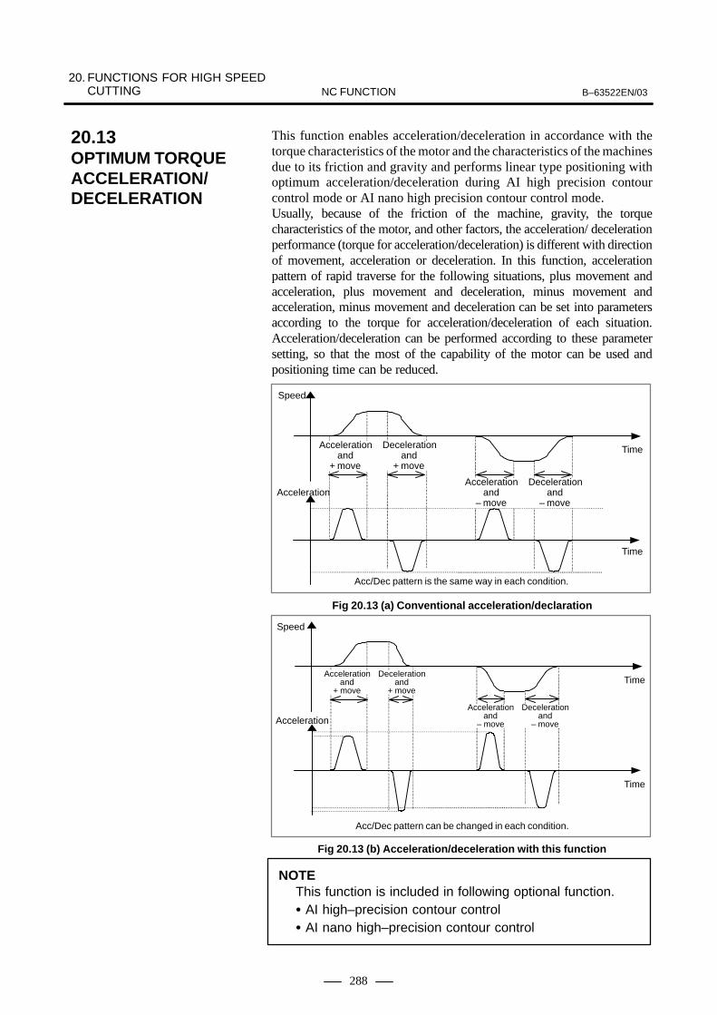
20. FUNCTIONS FOR HIGH SPEED CUTTING B–63522EN/03NC FUNCTION
288
This function enables acceleration/deceleration in accordance with thetorque characteristics of the motor and the characteristics of the machinesdue to its friction and gravity and performs linear type positioning withoptimum acceleration/deceleration during AI high precision contourcontrol mode or AI nano high precision contour control mode.Usually, because of the friction of the machine, gravity, the torquecharacteristics of the motor, and other factors, the acceleration/ decelerationperformance (torque for acceleration/deceleration) is different with directionof movement, acceleration or deceleration. In this function, accelerationpattern of rapid traverse for the following situations, plus movement andacceleration, plus movement and deceleration, minus movement andacceleration, minus movement and deceleration can be set into parametersaccording to the torque for acceleration/deceleration of each situation.Acceleration/deceleration can be performed according to these parametersetting, so that the most of the capability of the motor can be used andpositioning time can be reduced.
Speed
Accelerationand
+ move
Decelerationand
+ move
Accelerationand
– move
Decelerationand
– move
Time
Time
Acceleration
Acc/Dec pattern is the same way in each condition.
Fig 20.13 (a) Conventional acceleration/declaration
Speed
Time
Acceleration
Time
Accelerationand
+ move
Decelerationand
+ move
Accelerationand
– move
Decelerationand
– move
Acc/Dec pattern can be changed in each condition.
Fig 20.13 (b) Acceleration/deceleration with this function
NOTEThis function is included in following optional function.� AI high–precision contour control� AI nano high–precision contour control
20.13OPTIMUM TORQUE ACCELERATION/DECELERATION (M series)

B–63522EN/03 21. AXES CONTROLNC FUNCTION
289
21 AXES CONTROL

21. AXES CONTROL B–63522EN/03NC FUNCTION
290
Normally, the machine is controlled to move to a commanded position.However, when the follow up function is applied, actual position in theCNC is revised according to the move of the machine.Follow up function is activated when: - Emergency stop is onBecause machine movement during the emergency stop is reported, theactual position of the machine is reflected in the CNC. Therefore,machining can be resumed after the emergency stop has been deactivated,without performing the reference point return again.However, when a trouble has generated in the position detection system,the system cannot follow up correctly. So present position in CNC doesnot become correct value.By input signal (follow up signal) from PMC follow up function can alsobe applied to: - Servo off status. It is also valid in cases when the machine is moved with amechanical handle.
It is possible to move the machine by hand, using the mechanical handleinstalled on the machine; not by the NC (servo motor). Move distance by the mechanical handle is followed up and actualposition in The NC is revised. The mechanical handle feed is done byinputting the servo off signal of the axis fed. It is necessary, however, tospecify following up of the movement in the servo off status with thefollow up signal.
Servo on/off control per axis is possible by input signals from PMC. Thisfunction is generally used with the machine clamp.
The MDI-commanded or the program-commanded move direction ofeach axis can be reversed and executed.Mirror image is set by MDI setting or by input signals from PMC.Mirror image can be applied to each axis.
It is possible to detach or attach rotary tables and attachments with thisfunction. Switch control axis detach signal according to whether therotary tables and attachments are attached or detached. When this signalis on, the corresponding axis is excluded from the control axes, so theservo alarm applied to the axis are ignored. The axis is automaticallyregarded as being interlocked. This signal is not only accepted whenpower turned is on, so automatic change of attachments is possible anytime with this function. The same switching as with this signal can also be performed with theMDI setting.
21.1FOLLOW UP FUNCTION
21.2MECHANICALHANDLE FEED
21.3SERVO OFF
21.4MIRROR IMAGE
21.5CONTROL AXIS DETACH

B–63522EN/03 21. AXES CONTROLNC FUNCTION
291
An input signal from PMC can be used to select whether simplesynchronization control is performed. During simple synchronizationcontrol, the move command for the master axis is issued to the two motorsof the master and slave axes for synchronization control of the two axes.However, there are no functions for performing synchronizationcompensation so that the positional deviations of the master and slaveaxes are equalized by constantly monitoring these positional deviations.Even during simple synchronization control, pitch error compensationand backlash compensation for the master axis are performed separatelyfrom those for the slave axis.The following shows the differences in simple synchronization controlbetween the M series and the T series.
For M series� Operation modes that allow simple synchronization control
Automatic operation, Jog feed, Manual handle feed,Incremental feed, and Manual Reference position return
� Number of synchronized pairs
Up to four (depending on the number of control axes)
� Other functions
Synchronization error check (positional deviation/machinecoordinates)Synchronization (During power–up of the CNC, the departuregenerated during power–down of the CNC is automaticallycompensated. However, the absolute–position detectors are requiredfor the master and slave axes.)Automatic grid positioningTorque difference alarm
For T series� Operation modes that allow simple synchronization control
Automatic operation only (disabled during manual operation)
� Number of synchronized pairs
One
� Other functions
None
21.6SIMPLESYNCHRONOUSCONTROL

21. AXES CONTROL B–63522EN/03NC FUNCTION
292
The synchronization control function enables the synchronization ofmovements on two axes. If a move command is programmed for one ofthose two axes (master axis), the function automatically issues the samecommand to the other axis (slave axis), thus establishing synchronizationbetween the two axes. The parking state can be selected to suppressmovement of the slave axis, even if a move command is specified for themaster axis. If the parking state is used with the synchronization controlfunction, the operation can be controlled as follows:
(1)Synchronizes the movement on the slave axis with that of the masteraxis.
(2)Performs slave axis movement according to the move commandprogrammed for the master axis. However, the movement specifiedby the command is not made for the master axis itself (master parking).
(3)Updates the slave axis coordinates according to the distance travelledalong the master axis. However, no movement is made for the slaveaxis (slave parking).
CAUTIONIn the synchronization control described above, an identicalmove command is simultaneously output for two servoprocessing systems. Positional error between the two servomotors is not monitored nor is either servo motor adjustedto minimize the error. That is, synchronization errorcompensation is not carried out.
21.7SYNCHRONIZATIONCONTROL(ONLY AT 1–PATH CONTROL) (T series)
T series
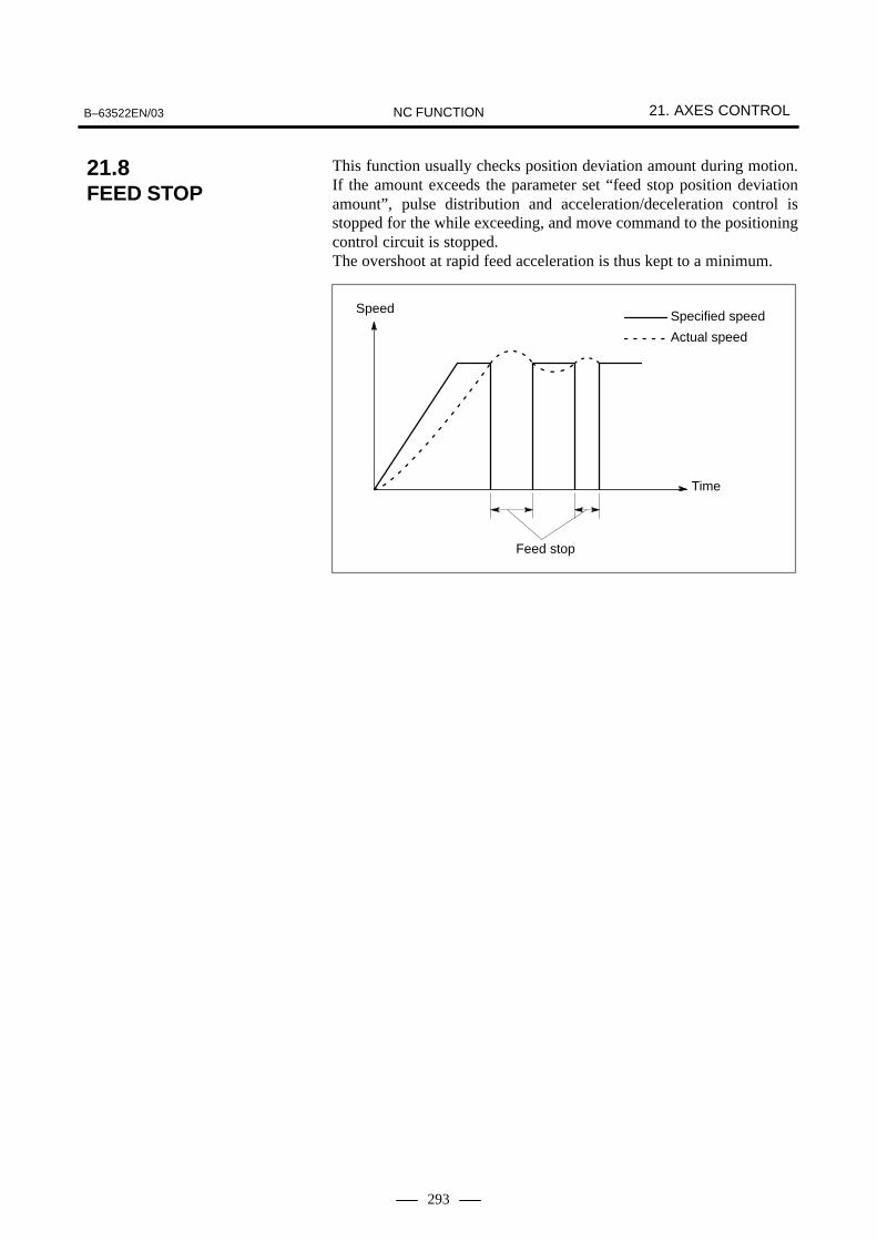
B–63522EN/03 21. AXES CONTROLNC FUNCTION
293
This function usually checks position deviation amount during motion.If the amount exceeds the parameter set “feed stop position deviationamount”, pulse distribution and acceleration/deceleration control isstopped for the while exceeding, and move command to the positioningcontrol circuit is stopped.The overshoot at rapid feed acceleration is thus kept to a minimum.
Feed stop
Speed
Time
Specified speed
Actual speed
21.8FEED STOP

21. AXES CONTROL B–63522EN/03NC FUNCTION
294
The rotation axis (C axis) can be controlled by commanding the G41.1 orG42.1 so that the tool constantly faces the direction perpendicular to theadvancing direction during cutting.
: Normal direction control cancellation mode (No normal direction control can be performed.)
: Normal direction control left side on(Control is made to allow facing perpendicular to advancing direction to the left)
: Normal direction control right side on (Control is made to allow facing perpendicular to advancing direction to the right)
G40.1
G41.1
G42.1
In the normal direction control, control is made so that the tool may beperpendicular to the advancing direction on the X-Y plane. With the angle of C axis, the +X direction is defined to be 0 degreesviewed from the rotation center of C axis. Then, the +Y direction, –Xdirection, and –Y direction are defined to be 90, 180, and 270 degrees,respectively. When shifting to the normal direction control mode from the cancellationmode, the C axis becomes perpendicular to the advancing direction wherethe G41.1 or G42.1 is at the starting point of commanded block.
Rotationcenter
+Y
+X0°
90°
180°
270°
Between blocks, the traveling of C axis is automatically inserted so thatthe C axis faces the normal direction at the starting point of each blockaccording to the change of traveling direction.Normal direction control is performed for the path after compensationduring the cutter compensation mode. The feed rate of rotation of C axisinserted at the starting point of each block becomes the federate set byparameters. However, when dry run is valid, the feed rate is set to the dryrun rate. Also, in the case of rapid traverse (GOO), it becomes the rapidtraverse rate. In the case of circular command, the C axis is allowed tobe rotated first so that the C axis faces perpendicular to the circular startingpoint. At this time, the C axis is controlled so that it constantly faces thenormal direction along with the move of circular command.
21.9NORMAL DIRECTIONCONTROL (G40.1,G41.1,G42.1) (M series)
M series
Format

B–63522EN/03 21. AXES CONTROLNC FUNCTION
295
NOTEThe rotation of C axis during normal direction control iscontrolled at short distance so that 180 degrees or less mayresult.

21. AXES CONTROL B–63522EN/03NC FUNCTION
296
A polygonal figure can be machined by turning the workpiece and toolat a certain ratio.�Rotation ratio of the workpiece and tool�Number of tool teeth
The polygon can be a quadrilateral or hexagon according to the abovemachining conditions.Compared with the machining performed by using C and X axes withpolar-coordinate compensation, this machining requires shorter time. It,however, cannot form a precise figure of a polygon. Generally, thismethod is used for machining of square or hexagonal bolt heads orhexagonal nuts.
Example)Rotation ratio of the workpiece and tool : 1 : 2Number of teeth : Three at every 120° (for a hexagon)
ÇÇÇÇÇÇÇÇÇÇÇÇÇÇÇÇÇÇÇÇÇÇÇÇÇÇÇÇÇÇÇÇÇÇÇÇ
Workpiece
Tool
The rotation of the tool for polygonal turning is controlled by the CNCcontrol axis. Hereafter, the rotation axis of this tool is called B axis.Command G51.2 controls the B axis so that the ratio of the tool speed tothe speed of the workpiece (specified by the S command beforehand)attached to the spindle becomes the specified value.The synchronization between the spindle and B axis is canceled by thecommand below. G50.2 ;
21.10POLYGONALTURNING(G50.2, G51.2) (T series)
T series

B–63522EN/03 21. AXES CONTROLNC FUNCTION
297
G51.2 P_ Q_ ;
P and Q : Rotation ratio of spindle to B axis
Command range : Integer value of 1 to 9 for both P and Q
When the value of Q is positive, the rotation direction of B axis is in positive direction.
When the value of Q is negative, the rotation direction of B axis is in negative direction.
(Example) When the rotation ratio of spindle to B axis is equal to 1 : 2 and the rotation direction of B axis is positive direction G51.2 P1 Q2 ;
G50.2 ; Cancel
When synchronous start is commanded by the G51.2, one rotation signalfrom the position coder mounted in the spindle is detected and the rotationof B axis is controlled while being synchronous with the rate of spindlein response to the rotation ratio (P : Q). Namely, control is made so thatthe ratio of spindle to B axis is P : Q. This relationship continues untilthe synchronous cancellation command (G50.2 or reset) are carried out.The direction of rotation of B axis is determined by the symbol Q and isnot affected by the direction of rotation of position coder. When the G50.2 is commanded, the synchronization of the spindle andB axis is canceled and the B axis is stopped.
Format

21. AXES CONTROL B–63522EN/03NC FUNCTION
298
In the polygonal turning with two spindles, the first spindle is used as aworkpiece rotation axis (master axis). The second spindle is used as a toolrotation axis (polygon synchronization axis). Spindle rotation control isapplied to both spindles with a constant ratio.The polygonal turning with two spindles can use different spindle speedsfor the same workpiece, because it performs automatic phasecompensation when a polygon synchronization mode command is issuedor the S command is changed during polygon synchronization mode.With this function, it is also possible to specify the phase differencebetween the master and polygon synchronization axes.
The PMC can directly control any given axis, independently of the CNC.In other words, moving the tool along axes that are not controlled by theCNC is possible by entering commands, such as those specifying movimgdistance and feedrate, from the PMC. This enables the control of turrets,pallets, index tables and other peripheral devices using any given axes ofthe CNC.Whether the CNC or PMC controls an axis is determined by the inputsignal provided for that particular axis.The PMC can directly control the following operations :
(1) Rapid traverse with moving distance specified(2) Cutting feed–feed per minute, with moving distance specified(3) Cutting feed–feed per revolution, with moving distance specified(4) Skip–feed per minute, with moving distance specified(5) Dwell(6) Continuons feed(7) Reference position return(8) 1st reference position return(9) 2nd reference position return(10) 3rd reference position return(11) 4th reference position return(12) External pulse synchronization–Main spindle(13) External pulse synchronization–first manual handle(14) External pulse synchronization–second manual handle(15) External pulse synchronization–third manual handle (for M series
only)(16) Feedrate control(17) Auxiliary function, Auxliary function 2, Auxliary function 3(18) Selection of the machine coordinate system(19) Torque control command
The PMC is provided with four paths to control these operations usinginput and output signals.By issuing commands through these four paths, the PMC cansimultaneously control multiple axes separately. Use parameter todetermine which path controls which axis. Commands may be issuedthrough one path to two or more axes, thus allowing the PMC to controlmultiple axes using one path.
21.11POLYGONALTURNING WITH TWOSPINDLES (T series)
T series
21.12AXIS CONTROL WITHPMC

B–63522EN/03 21. AXES CONTROLNC FUNCTION
299
For T series, even if the X axis is not vertical to the Z axis (for T series,the Y axis not vertical to the Z axis), they are assumed to form aorthogonal coordinate system, simplifying programming. The movementof each axis is automatically controlled according to the slant angle.
X’ X
Z
θ
Y’ Y
Z
θ
For T series For M series
Command
Machine movement
For the ordinary angular axis control function of the T series, the X–axisis always used as the angular axis, while the Z–axis is always used as theperpendicular axis. (For the M series, the Y–axis is always used as theangular axis, while the Z–axis is always used as the perpendicular axis.)With arbitrary axis angular axis control, however, any axes can bespecified as the angular and perpendicular axes, by specifying parametersaccordingly.
This function sets an axis (B–axis) independent of the basic controlledaxes X1, Z1, X2, and Z2 and allows drilling, boring, or other machiningalong the B–axis, in parallel with the operations for the basic controlledaxes. The X2 and Z2 axes can be used in two–path control mode.
Z1
WorkpieceThirdtool post
First tool post
B
Secondtool post
X1
Z2
X2
21.13ANGULAR AXISCONTROL
21.14ARBITRARYANGULAR AXISCONTROL
21.15B–AXIS CONTROL (T series)
T series

21. AXES CONTROL B–63522EN/03NC FUNCTION
300
When enough torque for driving a large table cannot be produced by onlyone motor, two motors can be used for movement along a single axis.Positioning is performed by the main motor only. The sub motor is usedonly to produce torque. With this tandem control function, the torqueproduced can be doubled.
Table
Ball screw
Main motor
Sub motor
Example of operation
In general, the CNC regards tandem control as being performed for oneaxis. However, for servo parameter management and servo alarmmonitoring, tandem control is regarded as being performed for two axes.
21.16TANDEM CONTROL

B–63522EN/03 21. AXES CONTROLNC FUNCTION
301
When contour grinding is performed, the chopping function can be usedto grind the side face of a workpiece. By means of this function, whilethe grinding axis (the axis with the grinding wheel) is being movedvertically, a contour program can be executed to instigate movementalong other axes. In addition, a servo delay compensation function is supported forchopping operations. When the grinding axis is moved vertically at highspeed, a servo delay and acceleration/deceleration delay occur. Thesedelays prevent the tool from actually reaching the specified position. Theservo delay compensation function compensates for any displacement byincreasing the feedrate. Thus, grinding can be performed almost up to thespecified position.There are two types of chopping functions: that specified byprogramming, and that activated by signal input.
Time
R point
Upper dead point
Lower dead point
G81.1 Z__ Q__ R__ F__ ;
Z : Upper dead point (For an axis other than the Z–axis, specify the axis address.)
Q : Distance between the upper dead point and lower dead point(Specify the distance as an incremental value, relative to the upper dead point.)
R : Distance from the upper dead point to point R(Specify the distance as an incremental value, relative to the upper dead point.)
F : Feedrate during chopping
G80; Cancels chopping
21.17CHOPPINGFUNCTION (G80, G81.1) (M series)
M series
Explanations
Format

21. AXES CONTROL B–63522EN/03NC FUNCTION
302
Gears can be cut by turning the workpiece (C–axis) in sync with therotation of the spindle (hob axis) connected to a hob.Also, a helical gear can be cut by turning the workpiece (C–axis) in syncwith the motion of the Z–axis (axial feed axis).
Spindle
C–axis
Gear material
Helical gear
Hob
��� � � � � � � � �
T : Number of teeth (Specifiable range: 1 to 5000)
L : Number of hob threads (Specifiable range: 1 to 20 with a sign)
⋅ The sign of L specifies the direction of rotation of the C–axis.
⋅ If L is positive, the C–axis rotates in the positive direction (+).
⋅ If L is negative, the C–axis rotates in the negative direction (–).
Q : Module or diametral pitchFor metric input, specify a module.(Units: 0.00001 mm, Specifiable range: 0.01 to 25.0 mm)For inch input, specify a diametral pitch.(Units: 0.00001 inch–1, Specifiable range: 0.01 to 250.0 inch–1)
P : Gear helix angle(Units: 0.0001 deg, Specifiable range: –90.0 to +90.0 deg)
P and Q must be specified when a helical gear is to be cut.
G80 ; Cancels synchronization between the hob axis and C–axis.
21.18HOB
21.18.1Hobbing MachineFunction (G80, G81) (Mseries)
M series
Format

B–63522EN/03 21. AXES CONTROLNC FUNCTION
303
Code<M series> Group Function
G80
00
Cancels hobbing synchronization.
G81
00
Starts hobbing synchronization.
G82 00 Cancels the C–axis servo delay compensation.
G83
00
Executes the C–axis servo delay compensation.
G84 Stores the C–axis servo delay compensation.
Canned cycles cannot be used when the hobbing machine function isenabled.
G81.4 T _ L _ Q _ P _ ;
T : Number of teeth (specifiable range: 1 to 500)
L : Number of hob threads (specifiable range: 1 to 30 with a sign)� The sign of L specifies the direction of rotation of the C–axis.� If L is positive, the C–axis rotates in the positive direction (+).� If L is negative, the C–axis rotates in the negative direction (–)
Q : Module or diametral pitchFor metric input, specify a module.(Units = 0.00001 mm; specifiable range = 0.01 to 25.0 mm)For inch input, specify a diametral pitch.(Units = 0.00001 inch–1; specifiable range = 0.01 to 250.0 inch–1)
P : Gear helix angle(Units = 0.0001 deg; specifiable range = –90.0 to +90.0 deg)
P and Q must be specified when a helical gear is to be cut.
G80.4 ; Cancels synchronization between the hob axis and C–axis.
Code<T series> Group Function
G80.4
00
Cancels hobbing synchronization.
G81.4
00
Starts hobbing synchronization.
G82.4 00 Cancels the C–axis servo delay compensation.
G83.4
00
Executes the C–axis servo delay compensation.
G84.4 Stores the C–axis servo delay compensation.
� During hobbing synchronization, a canned cycle (G81 to G89) cannotbe specified. If the prohibited specification is attempted, alarm 184will be raised.
� In the canned cycle mode, the hobbing synchronization commandG81.4 cannot be specified. If the prohibited specification is attempted,alarm 187 will be raised.
� G code list
� Canned cycle
21.18.2Hobbing Function(G80.4, G81.4) (Tseries)
T series
Format
� G code list
� Canned cycle

21. AXES CONTROL B–63522EN/03NC FUNCTION
304
To machine (grind/cut) a gear, the rotation of the workpiece axisconnected to a servo motor is synchronized with the rotation of the toolaxis (grinding wheel/hob) connected to the spindle motor. Tosynchronize the tool axis with the workpiece axis, an electric gear box(EGB) function is used for direct control using a digital servo system.With the EGB function, the workpiece axis can trace tool axis speedvariations without causing an error, thus machining gears with greatprecision.A dedicated servo axis is also used for the tool axis, connected to thespindle motor and for which the rotational position must be read directlyby the digital servo system (this axis is called the EGB axis).
Positioncontrol
Error counter
Synchronizationcoefficient
DMR
Spindle amplifier
CNC
Tool axis rotation command
Servo amplifier C–axis Detector
PC
Spindlemotor
Tool axis
Positiondetector
Positioncoder
α pulses/rev
Feedback connector for workpiece axis
Feedback connector for EGB axis
Command connector for EGB axis(dummy connector not required)
β pulses/rev
Synchroniza-tion switch
+
–+
Work pieceaxis
EGB axis
+
G81 T _ L _ Q _ P _ ; Starts synchronization.T : Number of teeth
L : Number of hob threads
Q : Module or diametral pitchSpecify a module in the case of metric input.Specify a diametral pitch in the case of inch input.
P : Gear helix angle
G80: Cancels synchronization
21.19SIMPLE ELECTRIC GEAR BOX (G80, G81) (M series)
M series
Format

B–63522EN/03 21. AXES CONTROLNC FUNCTION
305
This function validates a skip signal or high–speed skip signal for theworkpiece axis in the synchronization mode set by the EGB (ElectronicGear Box) function.This function has these features.
– The block with this function is not interrupted until the skip signalinput has been counted to the commanded times.
– The synchronization mode set by the EGB is not canceled by a skipsignal.
– The machine coordinates when a skip signal is input are stored inspecified custom macro variables successively.
– The number of times a specified skip signal is input is stored in acustom macro variable.
���� ��� α �� �� �� ���� ���� ��������
α : EGB axis (Workpiece axis)
P : The top number of custom macro variables in which the value ofmachine coordinate is set when skip signal is input.
Q : The total times of skip signal input during execution of the blockwith G31.8.
R : The number of custom macro variable in which the total numberof times of skip signal inputs is set.
21.20SKIP FUNCTION FOREGB AXIS (M series)
M series
Format

21. AXES CONTROL B–63522EN/03NC FUNCTION
306
This function is a function for rotating a workpiece in sync with a rotatingtool, or to move a tool in sync with a rotating workpiece. With thisfunction, the high–precision machining of gears, threads, and the like canbe implemented. A desired synchronization ratio can be programmed. Upto two sets of axes can be synchronized. A gear grinding machine can becontrolled, for instance, by using one axis for rotating the workpiece insync with the tool and another axis for performing dressing in sync withthe tool.The specification method differs depending on the configuration of themachine. For details, refer to the manual supplied by the machine toolbuilder.
Fifth axisSlave axis
Fourth axisDummy axisFollow–up
Third axisSlave axis
First axis X (omitted)Second axis Y (omitted)
+
–
CNCSpindle amplifier Motor SpindleSpindle (master axis)
Fourth axisDummy axisFollow–up
EGBC
–
+
+
–
+
K1 : Synchronization factor
EGBV
=
+
K�
Error counter
Synchronization switch
Motor
Detector
Speed/current control Servo amplifierPosition control
Workpiece axis
C–axis
K�
Dressing axis
–
+
Error counter
Synchronization switch
Speed/current controlPosition control
Detector
K2 : Synchronization factor
Motor
Detector
Servo amplifier C–axis
Tool axis
21.21ELECTRIC GEAR BOXTWO PAIR (M series)
M series

B–63522EN/03 21. AXES CONTROLNC FUNCTION
307
�������
��
β �β ��
Amount of travel relative to the master axis (Specify either Tt or Pp.)Tt : Speed of the master axisPp : Number of pulses for the master axis
Amount of travel relative to the slave axis(Specify either β j or β 0Ll.)β j : β is the address of a slave axis.
j is the amount of travel along the slave axis.β 0L�l : β is the address of a slave axis.
l is the speed of the slave axis.
Format
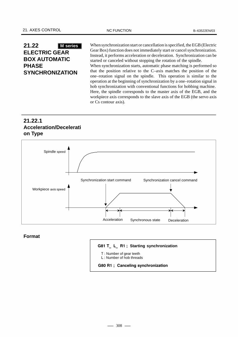
21. AXES CONTROL B–63522EN/03NC FUNCTION
308
When synchronization start or cancellation is specified, the EGB (ElectricGear Box) function does not immediately start or cancel synchronization.Instead, it performs acceleration or deceleration. Synchronization can bestarted or canceled without stopping the rotation of the spindle.When synchronization starts, automatic phase matching is performed sothat the position relative to the C–axis matches the position of theone–rotation signal on the spindle. This operation is similar to theoperation at the beginning of synchronization by a one–rotation signal inhob synchronization with conventional functions for hobbing machine.Here, the spindle corresponds to the master axis of the EGB, and theworkpiece axis corresponds to the slave axis of the EGB (the servo axisor Cs contour axis).
Synchronization cancel commandSynchronization start command
Workpiece axis speed
Spindle speed
Synchronous stateAcceleration Deceleration
��� �� �� �� Starting synchronization
�� �� ���!"��# �$��%&���'�����
� � Number of gear teeth� � Number of hob threads
21.22ELECTRIC GEARBOX AUTOMATICPHASESYNCHRONIZATION(M series)
M series
21.22.1Acceleration/Deceleration Type
Format

B–63522EN/03 21. AXES CONTROLNC FUNCTION
309
Synchronization cancel commandSynchronization start command
Workpiece axis speed
Spindle speed
Synchronousstate
Acceleration DecelerationAutomaticphase matching
��� �� �� �( Starting synchronization
�� �( ���!"��# �$��%&���'�����
� � Number of gear teeth� � Number of hob threads
21.22.2Acceleration/Deceleration and AutomaticPhase Synchronization
Format
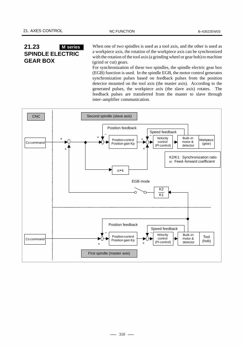
21. AXES CONTROL B–63522EN/03NC FUNCTION
310
When one of two spindles is used as a tool axis, and the other is used asa workpiece axis, the rotation of the workpiece axis can be synchronizedwith the rotation of the tool axis (a grinding wheel or gear hob) to machine(grind or cut) gears.For synchronization of these two spindles, the spindle electric gear box(EGB) function is used. In the spindle EGB, the motor control generatessynchronization pulses based on feedback pulses from the positiondetector mounted on the tool axis (the master axis). According to thegenerated pulses, the workpiece axis (the slave axis) rotates. Thefeedback pulses are transferred from the master to slave throughinter–amplifier communication.
–+ Velocity
control (PI control)
Position controlPosition gain KpCs command
CNC Second spindle (slave axis)
–
+
–
+
–+
+
Position feedbackSpeed feedback
EGB mode
K2/K1: Synchronization ratioα: Feed–forward coefficient
Workpiece(gear)
Built–in motor & detector
K2
K1
+
+
First spindle (master axis)
Position feedbackSpeed feedback
���
Cs commandPosition controlPosition gain Kp
Velocity control
(PI control)
Built–in motor & detector
Tool(hob)
21.23SPINDLE ELECTRICGEAR BOX (M series)
M series

B–63522EN/03 21. AXES CONTROLNC FUNCTION
311
��� �� �� �� �� )��&�� �$��%&���'������
�� ���!"� �$��%&���'������
� � ��� �� �����
� � ��� �� ��� �� ����
� � ����� � ����� �� �����
������� � ���� �� ��� ���� �� �� �� �����
������� � ����� �� ����� �� ��� ���� �� ���� �����
� � ��� ���� ��!��
Format

21. AXES CONTROL B–63522EN/03NC FUNCTION
312
This function applies to hobbing machines and other machines thatrequire synchronization of multiple sets of axes with various gear ratios.This function allows up to four individual sets to be synchronizedindependently. This can implement features specific to the hobbingmachine such as synchronization between hobbing axis and a workpieceaxis, Z–C synchronization in helical gear cutting, and Y–Csynchronization in hobbing axis shift.
The specifications of flexible synchronization control are as follows:
1) The master axis number, slave axis number, and gear ratio are set inparameters.
2) There are four groups of these parameters. Synchronization of fourgroups can be performed at the same time.
3) For multiple master axes, one slave axis can also be specified.
4) Synchronization is started and canceled by DI signals from the PMC.When DI signal switching is to be made during automatic operation,a parameter–set M code must be used.
5) The two Cs axes can also be used as a master axis and slave axis.
6) Like the hobbing function, retraction is also possible.
7) Feedback pulses of the spindle operating as the Cs axis can be used forfeed per revolution.The command format is G95P_;, where P_ is the axis number of Csaxis.
NOTEThis function is included in the threading and synchronousfeed option.
Commandpulse
Positioncontrol
Spindle amplifier or
servo amplifierDetector
Spindle motor (Cs axis) or
servo motor
K
Slave axis
Synchronization switch
" � Synchronization factor
Master axis
#
# $
$
Commandpulse
Positioncontrol
Spindle amplifier or
servo amplifierDetector
Spindle motor (Cs axis) or
servo motor
21.24FLEXIBLESYNCHRONIZATIONCONTROL FUNCTION(M series)
M series
Block diagram

B–63522EN/03 21. AXES CONTROLNC FUNCTION
313
In a closed loop system equipped with a built–in absolute positiondetector (serial pulse coder) and incremental linear scale, a coordinatesystem is established at power–up by using absolute position data fromthe built–in absolute position detector. The subsequent position controlis performed using incremental data of the linear scale. Since the positionimmediately after power–up is a temporary position, manual referenceposition return is needed to obtain a correct position.When this function is used, a stroke limit check is enabled even beforereference position return, although the position at power–up is anapproximate position. Note that this function does not use theincremental linear scale as an absolute position detector.This function is optional.
Serial pulse coder (absolute position detector)
Linear scale (incremental)
Ordinary position control
CNC
Absolute position detection at power–up
Fig. 21.25 System using the temporary coordinate setting function
21.25TEMPORARY ABSOLUTE COORDINATE SETTING

21. AXES CONTROL B–63522EN/03NC FUNCTION
314
When the retract signal is driven to 1 in automatic operation mode ormanual operation mode, the tool can be moved (retracted) along aparameter–set axis by a parameter–set amount on the rising edge of thesignal. Upon completion of the retraction, the retract completion signalis output. This function is used to perform retraction to prevent the toolor workpiece from being damaged when an abnormality occurs duringmachining.
Retraction
ÅÅÅÅÅÅÅÅÅÅ
Machining direction: In automatic operation, automatic operation is halted.
21.26GENERAL–PURPOSERETRACTION

22. FUNCTIONS SPECIFIC TO 2–PATH CONTROLB–63522EN/03 NC FUNCTION
315
22 FUNCTIONS SPECIFIC TO 2–PATH CONTROL
Two paths can be independently controlled to cut the workpiecesimultaneously.
� Application to a lathe with one spindle and two tool posts (Tseries)Two tool posts can operate simultaneously to machine one workpieceattached to the spindle.For example, while one tool post performs external machining, theother path can perform internal machining. The machining time is thenreduced greatly.
Tool post 1
Tool post 2
Spindle
� Application to a lathe with two spindles and two tool posts (Tseries)Two tool posts can operate simultaneously to machine two workpiecesattached to two spindles. Since each tool post operates independently,the productivity is improved as if two lathes were usedsimultaneously.
Tool post 1
Tool post 2
Spindle 1 Spindle 2
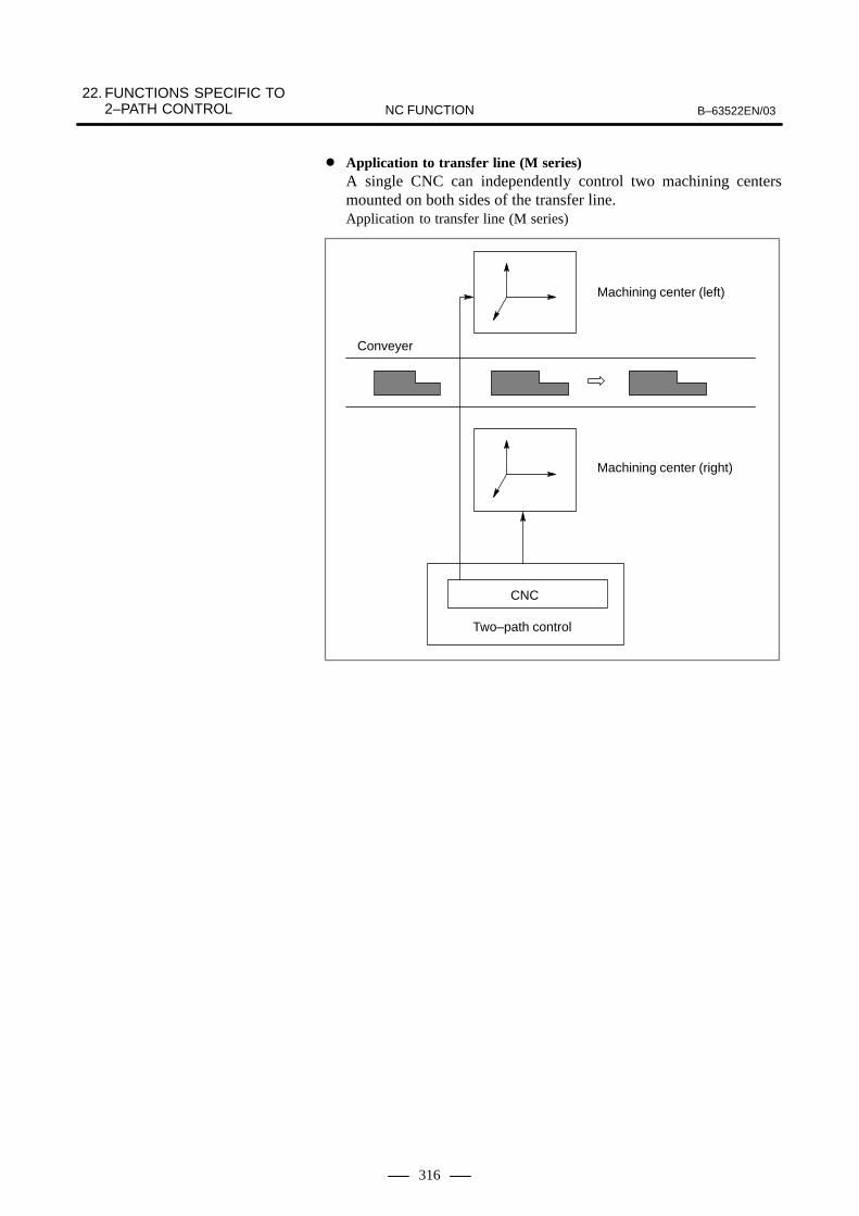
22. FUNCTIONS SPECIFIC TO 2–PATH CONTROL B–63522EN/03NC FUNCTION
316
� Application to transfer line (M series)A single CNC can independently control two machining centersmounted on both sides of the transfer line.Application to transfer line (M series)
CNC
Two–path control
Machining center (right)
Machining center (left)
Conveyer

22. FUNCTIONS SPECIFIC TO 2–PATH CONTROLB–63522EN/03 NC FUNCTION
317
� Controlling two paths simultaneously and independentlyThe movement of each path is separately programmed and stored inthe program memory for path. In automatic operation, this functionselects the program for path 1 and that for path 2 from the programmemory. When the paths are activated, the selected programs areexecuted simultaneously and independently. To make paths 1 and 2synchronous during machining, the synchronization function (Section22.1) can be used.
Programfor path 2
X1axis
Reader/punchinter-face
Programmemory forpath 1
path 2 con-trol (inter-polationand axiscontrol)
path 1 con-trol (inter-polationand axiscontrol)
Programmemory forpath 2
Programfor path 1
Y1axisZ1axis
Y2axis
X2axis
Z2axis
Only one MDI panel is provided for two paths. The path selection signalis used to switch the panel operation or display between paths 1 and 2.

22. FUNCTIONS SPECIFIC TO 2–PATH CONTROL B–63522EN/03NC FUNCTION
318
The M code controls the timing of paths 1 and 2 during machining. Whenthe synchronization M code is specified in the machining program of eachpath, the paths are synchronized at the specified block. During automaticoperation, if the synchronization M code is specified at one path, the pathwaits until the same M code is specified at the other path. After that, thenext block is executed.The range of the synchronization M codes to be used is set in a parameterbeforehand.
Example) The synchronization M codes are M100 to M300.
N2100 G01 X _ Z _ F _ ;
N2199 ············ ;M101 ;
Path 1 (N1100 to N1199) andpath 2 (N2100 to N2199) oper-ated simultaneously and inde-pendently
01357. ;G50 X _ Z _ ;G00 X _ Z _ T0101 ;S1000 M03 ;M100 ;
path 1 program
N1100 G01 X _ Z _ F _ ;
N1199 ············ ;M101 ;
M102 ;
02468 ;G50 X _ Z _ ;G00 X _ Z _ T0202 ;S2000 M03 ;M100 ;
path 2 program
Synchronization
[[Synchronization (M101)]]
N2200 S3000 ;G00 X _ Z _ T0202 ;
N229 ············ ;M102 ;
N2300 ············ ;G00 X _ Z _ T0707 ;
N2399 ············ ;M103 ;
Path 1 (N1300 to N1399) andpath 2 (N2300 to N2399) oper-ated simultaneously and inde-pendently
Synchronization
Synchronization
Only path 2 (N2200 to2299) operated
Synchronization
End of program
N1300 ············ ;G00 X _ Z _ T0505 ;
N1399 ············ ;M103 ;
[[Synchronization (M101)]]
M30 ; M30 ;
NOTE1 While a path is waiting because of a synchronization M code, if a different synchronization M
code is specified from the other path, an alarm occurs. Both paths, then stop operating.2 Unlike other M codes, the code signal and strobe signal are not output for the synchronization
M code.3 The synchronization signal is output from the path which is waiting.4 The synchronization-ignore signal can be used to ignore the synchronization M code specified
in the machining program. This signal is used when only one path is used for machining.
22.1WAITING FUNCTION

22. FUNCTIONS SPECIFIC TO 2–PATH CONTROLB–63522EN/03 NC FUNCTION
319
When one workpiece is machined by two tool posts operatingsimultaneously, paths may come close to each other. If these tool poststouch each other because of a program error or setting error, the tool oreven the machine may be damaged.If such an accident is expected, the tool post interference check functiondecelerates and stops the paths.
tool post 1
tool post 2
To execute the tool post interference check, the contour of each tool post(contour including the tool mounted on the path) must be set as acontact-inhibited area for each tool beforehand.This function checks if the contact-inhibited areas of these tool postsoverlap. If they overlap each other, it determines that the tool posts haveinterfered with each other, and decelerates them till they stop as an alarm.
CAUTIONFor this function, up to 64 tool offsets can be displayed orset as tool figure data (contact–inhibited areas).
22.2TOOL POST INTERFERENCECHECK (T series)
T series

22. FUNCTIONS SPECIFIC TO 2–PATH CONTROL B–63522EN/03NC FUNCTION
320
To machine a fine workpiece, two cutting tools should be applied on bothsides of a workpiece as shown below. When only one tool is applied, theother side of the workpiece may be deflected. Using two cutting tools canmake machining precision higher. If, however, these tools are not movedsynchronously, the workpiece will shake and machining will not be doneprecisely. The balance cut function makes paths move synchronously.
NOTEThe balance cut function cannot be used if the option ofmirror-image operation of facing paths is specified.
A machine with two paths has different custom macro common variablesand tool compensation memory areas for paths 1 and 2. paths 1 and 2 canshare the custom macro common variables and tool compensationmemory areas provided certain parameters are specified accordingly.
Paths 1 and 2 can share all or part of custom macro common variables#100 to #149 and #500 to #531, provided parameters are specifiedaccordingly. (The data for the shared variables can be written or read fromeither path.)
Path 2 can reference or specify the data in the tool compensation memoryarea of path 1, provided the parameter is specified accordingly. This canbe executed only when paths 1 and 2 have identical data for toolcompensation (number of groups, number of columns, unit system, etc.).
22.3BALANCE CUT (G68, G69) (T series)
T series
22.4MEMORY COMMON TO PATHS
� Custom macro commonvariables
� Tool compensationmemory (T series)

22. FUNCTIONS SPECIFIC TO 2–PATH CONTROLB–63522EN/03 NC FUNCTION
321
At two–path control, usually the axes belonging to tool post 1 (X1, Z1,...)are moved by the move command of tool post 1. The axes belonging totool post 2 (X2, Z2, ...) are moved by that of tool post 2 (individual pathcontrol). The synchronization/mix control function can move an optionalaxis of one tool post and that of the other tool post synchronously(synchronization control). This control function can exchange the movecommands for optional axes between two tool posts (mix control).
The axes belonging to tool post 1 (X1, Z1,...) are moved by the movecommand of tool post 1. The axes belonging to tool post 2 (X2, Z2, ...) aremoved by that of tool post 2.
ÇÇÇÇÇÇÇÇ
ÇÇÇÇÇÇÇÇÇÇ
X1 X2Z1
Z2
The move command for an axis (master axis) is given also to anotheroptional axis (slave axis). These two axes are then moved synchronously.The slave axis can be moved also by its own move command. Whichcommand to use can be selected by the synchronization control selectionsignal from PMC.
CAUTION1 Synchronization here means issuing the master axis move
command to the master axis and also to the slave axissimultaneously. The position deviation of master and slaveaxes is always detected. It, however, is not compensatedbecause synchronization compensation is not performed. Ifa deviation exceeding the limit set in the parameter isdetected, an alarm occurs and the movements of both axesare stopped.
2 The master axis and slave axis do not need to belong to thesame tool post. Two or more slave axes can be specified forone master axis.
22.5AXISRECOMPOSITION (T series)
T series
Explanations
� Individual tool postcontrol
� Synchronization control
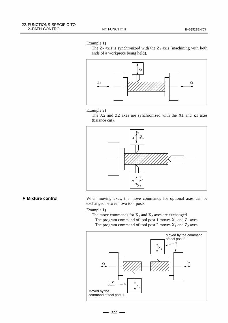
22. FUNCTIONS SPECIFIC TO 2–PATH CONTROL B–63522EN/03NC FUNCTION
322
Example 1)The Z2 axis is synchronized with the Z1 axis (machining with bothends of a workpiece being held).
ÇÇÇÇÇÇÇÇÇÇÇÇÇÇÇÇÇÇÇÇÇ
X1
Z2Z1
Example 2)The X2 and Z2 axes are synchronized with the X1 and Z1 axes(balance cut).
ÇÇÇÇÇÇÇÇÇÇÇÇÇÇÇÇ
X1Z1
X2
Z2
When moving axes, the move commands for optional axes can beexchanged between two tool posts.
Example 1)The move commands for X1 and X2 axes are exchanged.
The program command of tool post 1 moves X2 and Z1 axes.The program command of tool post 2 moves X1 and Z2 axes.
ÇÇÇÇÇÇÇÇÇÇ
ÇÇÇÇÇÇÇÇ
X1
X2
Z2Z1
Moved by the command of tool post 1.
Moved by the commandof tool post 2.
� Mixture control
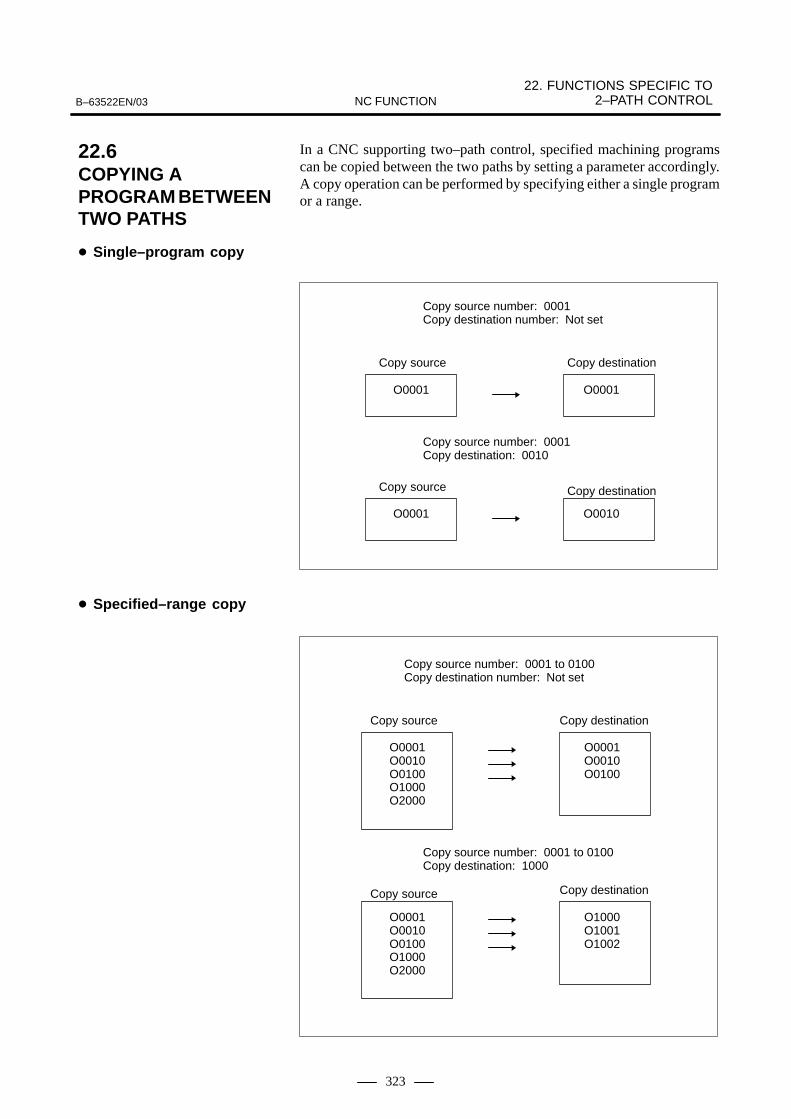
22. FUNCTIONS SPECIFIC TO 2–PATH CONTROLB–63522EN/03 NC FUNCTION
323
In a CNC supporting two–path control, specified machining programscan be copied between the two paths by setting a parameter accordingly.A copy operation can be performed by specifying either a single programor a range.
O0001 O0001
O0001 O0010
Copy source number: 0001Copy destination number: Not set
Copy source Copy destination
Copy source Copy destination
Copy source number: 0001Copy destination: 0010
Copy source
Copy source
O0001O0010O0100O1000O2000
O0001O0010O0100
O0001O0010O0100O1000O2000
O1000O1001O1002
Copy destination
Copy destination
Copy source number: 0001 to 0100Copy destination: 1000
Copy source number: 0001 to 0100Copy destination number: Not set
22.6COPYING A PROGRAM BETWEENTWO PATHS
� Single–program copy
� Specified–range copy

23. MANUAL OPERATION B–63522EN/03NC FUNCTION
324
23 MANUAL OPERATION

B–63522EN/03 23. MANUAL OPERATIONNC FUNCTION
325
� Jog feedEach axis can be moved in the + or - direction for the time the buttonis pressed. Feed rate is the parameter set speed with override of:0 - 655.34%, 0.01% step.The parameter set speed can be set to each axis.
� Manual rapid feed Each axis can be fed in a rapid feed to the + or - direction for the timethe button is pressed. Rapid traverse override is also possible.
Specified move amount can be positioned to the + or - direction with thebutton.Move amount of: (least command increment) x (magnification)can be specified. The feed rate is that of manual feed.The possible magnifications to be specified are as follows.×1, ×10, ×100, ×1000.
Increment system Metric input Inch input
IS–B 0.001, 0.01, 0.1, 1.0 0.0001, 0.001, 0.01, 0.1
IS–C 0.0001, 0.001, 0.01, 0.1 0.00001, 0.0001, 0.001, 0.01
By rotating the manual pulse generator, the axis can be moved for theequivalent distance. Manual handle feed is controlled 1 axis at a time.The manual pulse generator generates 100 pulses per rotation. Moveamount per pulse can be specified from the following magnifications:
×1, ×10, ×M, ×N.N is parameter set values of 0 - 1000. M is parameter set values of 1–127.Move distance is :(Least command increment) x (magnification)
Increment system Metric input Inch input
IS–B 0.001, 0.01, M/1000,N/1000 mm
0.0001, 0.001, M/10000,N/10000 inch
IS–C 0.0001, 0.001, M/10000,N/1000 mm
0.00001, 0.0001, M/100000,N/100000 inch
A 2nd, as well as 3rd manual pulse generator can be rotated to move theaxis for the equivalent distance. Manual handle feed of 3 axes (for Tsystem, 2 axes) can be done at a time. Multiplier is common to 1st, 2ndand 3rd manual pulse generators.
23.1JOG FEED
23.2INCREMENTAL FEED
23.3MANUAL HANDLE FEED (1ST)
23.4MANUAL HANDLE FEED (2ND, 3RD) (T SERIES: 2ND)

23. MANUAL OPERATION B–63522EN/03NC FUNCTION
326
Although manual handle feed is usually enabled only in the manualhandle-feed mode, it can also be performed in the manual continuous-feedmode by setting the corresponding parameters. However, manualcontinuous-feed and manual handle-feed cannot be performedsimultaneously. Manual handle-feed can be performed only when manualcontinuous-feed is in progress (i.e., an axis is moving).
The feedrates in jog feed and incremental feed can be specified byinputting either feed distance per minute or feed distance per rotation.
1 Specification of feed distance per minute or feed distanceper rotation is selected by setting the correspondingparameter.
2 During manual rapid traverse, feed distance per minute isalways specified.
When tool is moved by manual operation, whether to add the movedistance to the absolute coordinate value in the workpiece coordinatesystem is selected depending on the input signal *ABSM.When tool is moved by manual operation when *ABSM is set to 0, themove distance is added to the absolute coordinate value.When tool is moved by manual operation when *ABSM is set to 1, themove distance is ignored, and is not added to the absolute coordinatevalue. In this case, the work coordinates is shifted for the amount tool wasmoved by manual operation.
23.5HANDLE FEED IN THESAME MODE AS FORJOG FEED
23.6MANUALPER-ROTATION FEED(T series)
T series
23.7MANUAL ABSOLUTE ON/OFF

B–63522EN/03 23. MANUAL OPERATIONNC FUNCTION
327
The tool axis direction handle feed function allows the tool to be moveda specified distance by handle feed, along the axis of the tool, tilted byrotating the rotation axes.Tool axis direction handle feed function B provides two functions: handlefeed along the tool axis and that perpendicular to the tool axis.These functions are used for applications such as 5–axis diesinkingmachining.
When the tool axis direction handle mode is selected and the manual pulsegenerator is rotated, the tool is moved by the specified travel distance inthe direction of the tool axis tilted by the rotation of the rotary axis.
A&C,B&C
Workpiece
When the tool axis normal direction handle mode is selected and themanual pulse generator is rotated, the tool is moved by the specified traveldistance in the direction normal to the tool axis tilted by the rotation ofthe rotary axis.
A&C , B&C
X
Y
Z
AB
C
Tool
Transverse direction of the tool (X–axis)
Workpiece
Center of rotation
Longitudinal directionof the tool
Transverse directionof the tool (Y–axis)
A– and C–axesB– and C–axes
23.8TOOL AXIS DIRECTION HANDLE FEED AND TOOL AXISDIRECTION HANDLE FEED B (M series)
M series
23.8.1Tool Axis Direction Handle Feed
23.8.2Tool Axis NormalDirection Handle Feed

23. MANUAL OPERATION B–63522EN/03NC FUNCTION
328
In manual handle feed or jog feed, the following types of feed operationsare enabled in addition to the feed operation along a specified single axis(X–axis, Y–axis, Z–axis, and so forth) based on simultaneous 1–axiscontrol:
� Feed along a tilted straight line in the XY plane (M series) (linear feed)or in the ZX plane (T series) (linear feed) based on simultaneous2–axis control
� Feed along a circle in the XY plane (M series) (circular feed) or in theZX plane (T series) (circular feed) based on simultaneous 2–axiscontrol
Tool
Workpiece
Y or X Y or X
X or Z X or Z
Workpiece
Tool
<<Linear feed>> <<Circular feed>>
Once the CNC is put in the rigid tapping mode by issuing a programinstruction in the MDI mode, moving the taping axis with the manualhandle in the handle mode can cause rigid tapping to be performed.Manual rigid tapping is available when parameter is set.The program instruction is necessary to determine the lead of a screw tobe produced and enable the rigid tapping mode.The program instruction must always specify a tapping axis. However,a value specified in it must not cause the tapping axis to operate. Do notspecify an instruction for positioning to the position where a hole to bemade or to the R point; otherwise axis movement occurs.
(Example program)M29 S1000;G91 G84 Z0 F1000 ;
The spindle rotation direction for manual rigid tapping depends on thespecified tapping cycle G code and parameter.
23.9MANUALLINEAR/CIRCULARINTERPOLATION(ONLY AT 1–PATHCONTROL)
23.10RIGID TAPPING BY MANUAL HANDLEFEED (M series)
M series
B–63522EN/03 23. MANUAL OPERATIONNC FUNCTION
329
The manual numeric command function allows data programmedthrough the MDI to be executed in jog mode. Whenever the system isready for jog feed, a manual numeric command can be executed. Thefollowing eight functions are supported:
(1)Positioning (G00)
(2)Linear interpolation (G01)
(3)Automatic reference position return (G28)
(4)2nd/3rd/4th reference position return (G30)
(5)M codes (miscellaneous functions)
(6)S codes (spindle functions)
(7)T codes (tool functions) (M series)
(8)B codes (second auxiliary functions)
By setting the corresponding parameters, the following commands foraxial motion and the M, S, T, and B functions can be disabled:
(1)Positioning (G00)
(2)Linear interpolation (G01)
(3)Automatic reference position return (G28)
(4)2nd/3rd/4th reference position return (G30)
(5)M codes (miscellaneous functions)
(6)S codes (spindle functions)
(7)T codes (tool functions) (M series)
(8)B codes (second auxiliary functions)
At the end of manual feed or manual rapid traverse, this functioncarries out feed until absolute coordinates are automatically set torounded values (based on the unit of stop accuracy). The unit of stopaccuracy is specified by a relevant signal.In jog feed mode or teach in jog mode, this function starts on thefalling edge of a feed axis direction select signal (+J1 to +J8, –J8 to–J8), but does not start in any of the conditions below.
� Operation has been suspended due to a reset.
� Operation has been suspended due to an emergency stop.
� The mode has been changed.
� An alarm has been generated (the function is disabled while the alarmpersists).
� A jog override has been set to 0%.
� An interlock has been applied (see also CAUTION).
� The system is in manual reference position return mode (REF).
� The axis is currently subjected to three–dimensional coordinateconversion.
23.11MANUAL NUMERIC COMMAND
23.12THE STOP POSITIONSETTING WITH THEMANUAL FEED (Tseries)
T series

24. AUTOMATIC OPERATION B–63522EN/03NC FUNCTION
330
24 AUTOMATIC OPERATION

B–63522EN/03 24. AUTOMATIC OPERATIONNC FUNCTION
331
The part program can be read and executed block by block from the inputdevice connected to the reader/puncher interface.
Program registered in the memory can be executed.
Multiple blocks can be input and executed by the MDI unit.
24.1OPERATION MODE
24.1.1DNC Operation
24.1.2Memory Operation
24.1.3MDI Operation

24. AUTOMATIC OPERATION B–63522EN/03NC FUNCTION
332
Program number currently in need can be searched from the programsregistered in memory operating the MDI.
The sequence number of the program on the currently selected memorycan be searched using the MDI unit.When executing the program from half-way (not from the head) of theprogram, specify the sequence number of the half-way program, and theprogram can be executed from the half-way block by sequence numbersearch.
After program execution has ended, the program in the memory or thetape reader can be reminded to the program head, with this reset & rewindsignal on. (When a portable tape reader with reels is in use)
By specifying work numbers of 01 - 15 externally (from the machine side,etc.), program corresponding to the work number can be selected.The work number equals the program number. For example when worknumber 12 is specified, program, O0012 is selected.
The external workpiece number search function has been expanded. Aworkpiece number 0001 to 9999 can be specified to select a program(O0001 to O9999) corresponding to the workpiece number.
24.2SELECTION OF EXECUTIONPROGRAMS
24.2.1Program NumberSearch
24.2.2Sequence NumberSearch
24.2.3Rewind
24.2.4External WorkpieceNumber Search
24.2.5Expanded ExternalWorkpiece NumberSearch

B–63522EN/03 24. AUTOMATIC OPERATIONNC FUNCTION
333
Set operation mode to memory operation, MDI operation, or DNCoperation, press the cycle start button, and automatic operation starts.
Buffer register in CNC equivalent to one block is available for programread and control of CNC command operation intervals caused bypreprocess time.
24.3ACTIVATION OF AUTOMATICOPERATION
24.3.1Cycle Start
24.4EXECUTION OF AUTOMATICOPERATION
24.4.1Buffer Register
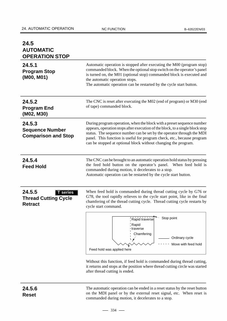
24. AUTOMATIC OPERATION B–63522EN/03NC FUNCTION
334
Automatic operation is stopped after executing the M00 (program stop)commanded block. When the optional stop switch on the operator’s panelis turned on, the M01 (optional stop) commanded block is executed andthe automatic operation stops.The automatic operation can be restarted by the cycle start button.
The CNC is reset after executing the M02 (end of program) or M30 (endof tape) commanded block.
During program operation, when the block with a preset sequence numberappears, operation stops after execution of the block, to a single block stopstatus. The sequence number can be set by the operator through the MDIpanel. This function is useful for program check, etc., because programcan be stopped at optional block without changing the program.
The CNC can be brought to an automatic operation hold status by pressingthe feed hold button on the operator’s panel. When feed hold iscommanded during motion, it decelerates to a stop.Automatic operation can be restarted by the cycle start button.
When feed hold is commanded during thread cutting cycle by G76 orG78, the tool rapidly relieves to the cycle start point, like in the finalchamfering of the thread cutting cycle. Thread cutting cycle restarts bycycle start command.
Stop point
Rapidtraverse
Rapid traverse
ChamferingOrdinary cycle
Move with feed hold
Feed hold was applied here
Without this function, if feed hold is commanded during thread cutting,it returns and stops at the position where thread cutting circle was startedafter thread cutting is ended.
The automatic operation can be ended in a reset status by the reset buttonon the MDI panel or by the external reset signal, etc. When reset iscommanded during motion, it decelerates to a stop.
24.5AUTOMATICOPERATION STOP
24.5.1Program Stop (M00, M01)
24.5.2Program End (M02, M30)
24.5.3Sequence NumberComparison and Stop
24.5.4Feed Hold
24.5.5Thread Cutting CycleRetract (T series)
T series
24.5.6Reset

B–63522EN/03 24. AUTOMATIC OPERATIONNC FUNCTION
335
This function allows program restart by specifying the desired sequencenumber, for example after tool break and change, or when machining isrestarted after holidays. The NC memorizes the modal status from thebeginning of the program to the sequence number. If there are M codes necessary to be output, output the M code by the MDI,press the start button, the tool automatically moves to the start position,and the program execution restarts.
These functions are used for replacing tools damaged retraction of toolsfor confirming the cutting conditions, and recovering the tools efficientlyto restart the cutting. Also, the escape operation can be performed with the tool retract signalby previously setting the escape amount (position) with a program. Thiscan be used for retraction for detecting tool damage.
1 Input the tool retract signal during executing the automatic operation.Then, the automatic operation is halted and the escape operation(retraction) is performed to the escape position commanded by theprogram.
2 Input the tool retract signal to initiate the retract mode.
3 After that, switch the automatic mode to the manual mode to movetools with manual operation such as the jog feed and handle feed. Amaximum of 10 points can be automatically memorized as travel path.
4 Input the tool recovery signal to return the tool to the retractionposition in the opposite direction along the path moved by manualoperation automatically (recovery operation).
5 Perform the cycle start to return the tool to the position where the toolretract signal was entered (repositioning). When the recoveryoperation completes, the halted automatic operation resumes.
24.6RESTART OF AUTOMATICOPERATION
24.6.1Program Restart
24.6.2Tool Retract & Recover

24. AUTOMATIC OPERATION B–63522EN/03NC FUNCTION
336
: Programmed escape position
: Position at which the tool retract signal was input
: Retraction path
: Position stored during manual operation
: Return operation
: Manual operation
: Repositioning
Command the escape amount using the G10.6.G10.6 �� _ ;
The escape data sorted by G10.6 is valid until the next G10.6 iscommanded. Command the following to cancel the escape amount:
G10.6 ; (Single command)
where The G10.6 is the one-shot G code. The tool can be retracted to a special location of work coordinate systemwhen the escape amount is command by the ABSOLUTE (G90). Whenthe escape amount is commanded by the INCREMENTAL (G91), the toolcan retract by only the commanded escape amount.
In cases such as when tool movement along an axis is stopped by feed holdduring automatic operation so that manual intervention can be used toreplace the tool: When automatic operation is restarted, this functionreturns the tool to the position where manual intervention was started.To use the conventional program restart function and tool withdrawal andreturn function, the switches on the operator’s panel must be used inconjunction with the MDI keys. This function does not require suchoperations.
24.6.3Manual Interventionand Return

B–63522EN/03 24. AUTOMATIC OPERATIONNC FUNCTION
337
During automatic operation, tool can be adjusted by the manual pulsegenerator without changing the mode. The pulse from the manual pulsegenerator is added to the automatic operation command and the tool ismoved for the recommended pulses. The work coordinate system thereafter is shifted for the pulse commandedvalue. Movement commanded by handle interruption can be displayed.
24.7MANUALINTERRUPTIONDURING AUTOMATICOPERATION
24.7.1Manual HandleInterruption

24. AUTOMATIC OPERATION B–63522EN/03NC FUNCTION
338
Any of the files (programs) stored on a FANUC Handy File, a FANUCProgram File Mate, a FANUC FLOPPY CASSETTE can be selected andexecuted.
� A list of the files stored on the Floppy Cassette can be displayed.
� Files can be executed in an arbitrary order and executed an arbitrarynumber of times by specifying file numbers in a desired order alongwith their repeat counts.
File list screen
FILE DIRECTORY F0004 N00020 CURRENT SELECTED:O0002 NO. FILE NAME (METER) VOL 0000 SCHEDULE 0001 PARAMETER 46.1 0002 ALL.PROGRAM 12.3 0003 O0001 1.9 0004 O0002 1.9 0005 O0003 1.9 0006 O0004 1.9 0007 O0005 1.9 0008 O0010 1.9
RMT **** *** *** 09:36:48[ SELECT ][ ][ ][ ][ ]
Schedule screen (for specifying file numbers and repeat counts)
FILE DIRECTORY F0000 N00020 ORDER FILE NO. REQ.REP CUR.REP 01 0001 2 0 02 0007 25 0 03 0008 6 0 04 0011 9999 0 05 0012 LOOP 0 06 07 08 09 10
>_ RMT **** *** *** 09:36:48[ PRGRM ][ ][ DIR ][ SCHDUL ][ (OPRT) ]
24.8SCHEDULINGFUNCTION
B–63522EN/03 24. AUTOMATIC OPERATIONNC FUNCTION
339
While a tape is running, a program input from an I/O device connectedto the reader/punch interface can be executed and stored in memory.Similarly, a program stored in memory can be executed and outputthrough the reader/punch interface at the same time.
With the retrace function, the tool can be moved in the reverse direction(reverse movement) by using the REVERSE switch during automaticoperation to trace the programmed path. The retrace function also enablesthe user to move the tool in the forward direction again (forward returnmovement) along the retraced path until the retrace start position isreached. When the tool reaches the retrace start position, the tool resumesmovement according to the program.
24.9SIMULTANEOUSINPUT AND OUTPUTOPERATIONS (ONLY AT 1–PATHCONTROL) (M series)
M series
24.10RETRACE FUNCTION(M series)
M series

24. AUTOMATIC OPERATION B–63522EN/03NC FUNCTION
340
When rigid tapping is stopped, either by an emergency stop or by a reset,the tap may cut into the workpiece. The tap can subsequently be drawnout by using a PMC signal. This function automatically storesinformation relating to the tapping executed most recently. When a tapreturn signal is input, only the rigid tapping cycle return operation isexecuted, based on the stored information. The tap is pulled toward theR point. When a return value � is set in a corresponding parameter, thepulling distance can be increased by �.
L L
α
α
Initial point2nd returncompletionpoint
1st returncompletionpointR point
Return completion point
Center oftapping
Z point (α = 0) (when α is set)
Instead of signal input, a G30 command can be used to start rigid tappingreturn. This is made possible by parameter setting.
��� ��� ��� �
M29 : A parameter–set M code that specifies rigid tappingS_ : Specify S used when rigid tapping is specified. (Optional)
NOTE1 When use of G30 is selected, rigid tapping return cannot be
performed by signal input.2 The rigid tapping return command is a one–shot command.
24.11RIGID TAPPING RETURN (M series)
M series
24.11.1Rigid Tapping Returnby Specifying G30
Format

B–63522EN/03 25. PROGRAM TEST FUNCTIONSNC FUNCTION
341
25 PROGRAM TEST FUNCTIONS

25. PROGRAM TEST FUNCTIONS B–63522EN/03NC FUNCTION
342
In machine lock condition, the machine does not move, but the positiondisplay is updated as if the machine were moving. Machine lock is valideven in the middle of a block.
Machine lock can be commanded per axis.
This function inhibits transmitting of M, S, T, B function code signals andstrobe signals to PMC. Miscellaneous functions M00, M01, M02, andM30 are executed even when miscellaneous function lock is applied,allowing the code signal, strobe signal, and decode signal to betransmitted normally.
In the dry run mode, the tool moves at the speed obtained by multiplyingthe dry run speed by the override value for manual feeding, regardless ofthe specified cutting federate. The dry run speed is specified in thecorresponding parameter. However, the rapid traverse command (G00)and rapid traverse override value are effective.Dry run can also be commanded to rapid feed command (G00) byparameter setting.
The program can be executed block by block under automatic operation.
25.1ALL-AXES MACHINE LOCK
25.2MACHINE LOCK ON EACH AXIS
25.3AUXILIARYFUNCTION LOCK
25.4DRY RUN
25.5SINGLE BLOCK
B–63522EN/03 25. PROGRAM TEST FUNCTIONSNC FUNCTION
343
During automatic operation, the program can be executed in the forwardor reverse direction by using the manual handle (the manual pulsegenerator). Program errors can be checked easily by performing thismanual handle operation while actually operating the machine.
� Check mode
In check mode, a program is executed in the forward or reversedirection to check the program. In check mode, this function createsdata for reverse execution during forward execution of the program.
� Forward
Forward execution means that a program is executed in the forwarddirection without rotating the manual pulse generator or by turning themanual pulse generator in the positive direction.
The program execution speed is proportional to the speed of themanual pulse generator. As the manual pulse generator is turned in thepositive direction quickly, the execution speed increases. As themanual pulse generator is turned slowly, the execution speeddecreases. The amount of travel per pulse of the manual pulsegenerator can be changed by changing the magnification in the sameway as ordinary handle feed.
� Reverse execution
Reverse execution means that a program once executed in the forwarddirection is executed in the reverse direction by turning the manualpulse generator in the negative direction.
Reverse execution of a program can be performed only for thoseblocks that have been executed in the forward direction. About up to200 blocks can be executed in the reverse direction; the allowablenumber of blocks for reverse execution varies depending on thecontents of a specified program.
The speed of the reverse execution of a program is proportional to thespeed of the manual pulse generator. As the manual pulse generatoris turned in the negative direction quickly, the execution speedincreases. As the manual pulse generator is turned slowly, theexecution speed decreases. The amount of travel per pulse of themanual pulse generator can be changed by changing the magnificationin the same way as ordinary handle feed.
25.6MANUAL HANDLE RETRACE (T series)
T series

26. SETTING AND DISPLAY UNIT B–63522EN/03NC FUNCTION
344
26 SETTING AND DISPLAY UNIT
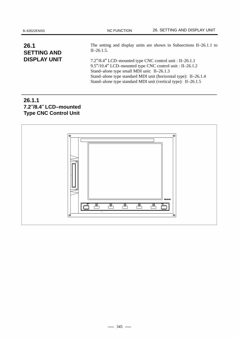
B–63522EN/03 26. SETTING AND DISPLAY UNITNC FUNCTION
345
The setting and display units are shown in Subsections II–26.1.1 toII–26.1.5.
7.2″/8.4″ LCD–mounted type CNC control unit : II–26.1.19.5″/10.4″ LCD–mounted type CNC control unit : II–26.1.2Stand–alone type small MDI unit: II–26.1.3Stand–alone type standard MDI unit (horizontal type): II–26.1.4Stand–alone type standard MDI unit (vertical type): II–26.1.5
26.1SETTING ANDDISPLAY UNIT
26.1.17.2″/8.4″ LCD–mountedType CNC Control Unit
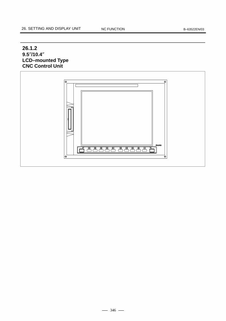
26. SETTING AND DISPLAY UNIT B–63522EN/03NC FUNCTION
346
26.1.29.5″/10.4″LCD–mounted TypeCNC Control Unit

B–63522EN/03 26. SETTING AND DISPLAY UNITNC FUNCTION
347
FUNCTION KEYS
ADDRESS/NUMERIC KEYS
PAGE–UP/DOWN KEYS
CURSOR KEYS
SHIFT KEYCANCEL KEY
INPUT KEY
EDIT KEYS
HELP KEY
RESET KEY
26.1.3Stand–alone TypeSmall MDI Unit

26. SETTING AND DISPLAY UNIT B–63522EN/03NC FUNCTION
348
INPUT KEY
CANCEL KEY
EDIT KEYS
SHIFT KEY
PAGE–UP/DOWN KEYS
CURSOR KEYS FUNCTION KEYS
ADDRESS/NUMERIC KEYSRESET KEYHELP KEY
26.1.4Stand–alone TypeStandard MDI Unit(Horizontal Type)

B–63522EN/03 26. SETTING AND DISPLAY UNITNC FUNCTION
349
ADDRESS/NUMERIC KEYSHELP KEY RESET KEY
FUNCTION KEYS
PAGE–UP/DOWN KEYS
CURSOR KEYSSHIFT KEY
EDIT KEYS
CANCEL KEY
INPUT KEY
26.1.5Stand–alone TypeStandard MDI Unit(Vertical Type)

26. SETTING AND DISPLAY UNIT B–63522EN/03NC FUNCTION
350
No. Key Function
(1)Reset key Used to reset the CNC to release an alarm or other similar state.
(2)
Help key Used to get help with operations such as for the MDI keys, when the operator doesnot know what to do next.For the 160i/180i/210i/160is/180is/210is, the Esc key on the personal computertakes the place of this key.
(3)Soft keys The soft keys are assigned different functions depending on the application.
The functions currently assigned to the soft keys are displayed on the lowermost lineof the screen.
(4)
Address/numeric keys Used to enter letters and numbers.
(5)
Shift key Some of the address keys have two different letters. When the shift key is pressedfirst before pressing one of these address keys, the lower-right letter is input. Whenthe shift key is pressed, ^ is displayed in the key input buffer indicating that the low-er-right letter will be input.
(6)
Input key Data input by pressing an address or numeric key is stored in the key input buffer,then displayed. When data input to the key input buffer needs to be written to theoffset register, press the <INPUT> key. This key is equivalent to soft key [INPUT].Either key may be used.
(7)
Cancel key Used to delete letters or numbers input to the key input buffer.Example)When N001X100Z is displayed on the key input buffer, pressing the cancel key de-letes the letter Z, and N001X100 is displayed.
(8)
Edit keys Used to edit programs.
: Alter
: Insert
: Delete
(9)
Function keys Used to switch screens for each function.For the 160i/180i/210i/160is/180is/210is, the Alt key on the personal computer
takes the place of and the Ctrl key takes the place of .CUSTOM
26.2EXPLANATION OF THE KEYBOARD

B–63522EN/03 26. SETTING AND DISPLAY UNITNC FUNCTION
351
No. FunctionKey
(10)
Cursor keys Four cursor keys are provided.
: Moves the cursor to the right or forwards in small units.
: Moves the cursor upward or backwards in large units.
: Moves the cursor downward or forwards in large units.
: Moves the cursor to left or backwards in small units.
(11)
Page-up/down keys Page-up and page-down keys are provided.
: Used to display the next page.
: Used to display the previous page.
The function keys select what is displayed. Each function is divided intosub-functions, and the sub-functions are selected by soft keys.
There are six function keys : POS , PROG , OFFSETSETTING , SYSTEM , MESSAGE , and GRAPH .
POS : Displays the current position.
PROG : Displays and edits a program stored in memory.
OFFSETSETTING : Displays an offset value, offset from the workpiece zero point,
custom macro variable, and tool life management data. Allowsdata to be input into these items.
SYSTEM : Displays and sets a parameter and pitch error compensation
value, and displays self diagnostic data.
MESSAGE : Displays an alarm message, external operator message, external
alarm message, and alarm history.
GRAPH : Displays graphic data.
CUSTOM : Press this key to display the custom screen (conversational
macro screen).In case of 160i/180i/210i/160is/180is/210is, this key is assignedto “Ctrl” key of the personal computer.To display the custom screen with the CNC screen display
function, press SHIFT + POS .
: In case of 160i/180i/210i/160is/180is/210is, this key is assigned
to “Alt” key of the personal computer.
26.2.1Explanation of theFunction Keys
26. SETTING AND DISPLAY UNIT B–63522EN/03NC FUNCTION
352
The MDI panel has 10 soft keys (or 5 soft keys), a next-menu key on theright, and a previous-menu key on the left. The next menu key andprevious menu key are used to select the functions of the soft keys.These soft keys can be assigned with various functions, according to theneeds. The following functions are mainly available via the MDI panel:
� Actual position display
� Contents of program display, program directory display (display ofprogram number, program name, part program storage length left,number of programs left)
� Program editing
� Offset amount display and setting
� Commanded value display, MDI input
� Parameter setting and display
� Alarm message/operator message display
� Custom macro variables display and setting
� Tool life management data display and setting
� Diagnosis
� Others
This manual may refer to a display device with 10 + 2 soft keys as a 12soft key type, and a display device with 5 + 2 soft keys as a 7 soft key type.
26.2.2Explanation of the SoftKeys

B–63522EN/03 27. DISPLAYING AND SETTING DATANC FUNCTION
353
27 DISPLAYING AND SETTING DATA
The display on the 160i/180i/210i/160is/180is/210is with a personalcomputer function differs from the display on the 16i/18i/21i with nopersonal computer function. This chapter presents the display screenswhen the personal computer function is not provided and explains howto make settings.To display standard CNC screens on the 160i/180i/210i/160is/180is/210is, use the CNC screen display function. For details of the CNC screendisplay function, refer to ”Screen Display Function Operator’s Manual(B–63164EN).”

27. DISPLAYING AND SETTING DATA B–63522EN/03NC FUNCTION
354
The following data are displayed. 7 soft keys can display maximum 640characters (40 × 16 lines) and 12 soft keys can display maximum 2080(80 × 26 lines).
The status of the control unit is indicated on the screen. Statuses includethe state when an alarm is being activated or when the system is in the editmode. The status line is displayed right above the soft key line.
EDIT STOP MTN FIN ALM hh:mm:ss HEAD1
––EMG––
�� � � �
�
� �
OUTPUT
StatuslineSoft keyline
� Operation mode (MDI, MEM, RMT, EDIT, HND, TJOG, THND,INC, or REF)
� Status of automatic operation (STOP, HOLD, STRT, or ****)***** : ResetSTOP : Automatic operation is in a stopped state.HOLD : Automatic operation is in a halt state.STRT : Automatic operation has been started.
� Axis movement/dwell (MTN, DWL, or ***)
� FIN wait state (FIN or ***)
� Emergency stop (--EMG--) (displayed above in 3 and 4)
� Alarm status (ALM, WNG, or ***)
� Clock (hh:mm:ss)
� Name of the path currently selected (only at 2–path control)
NOTEThe name of a path can be specified by the corresponding
parameter with a string of up to seven characters. The characters
may be numbers, letters, katakana characters, or symbols.
Status display such as program editing (INPUT, OUTPUT, SRCH,EDIT, LSK, or RSTR)(� and are displayed in the same column. When a program isbeing edited, is displayed.)
Data input via the address keys or the numerical keys are displayed at theleft lower part of the screen.
Program number, sequence number is displayed on the right upper partof the screen.
Alarm number and its contents are displayed briefly.
27.1DISPLAY
Explanations
Indication of statusesand tool post names
Key input display
Program number,sequence numberdisplay
Alarm display

B–63522EN/03 27. DISPLAYING AND SETTING DATANC FUNCTION
355
Alarm message contents are displayed.
Relative position and position in the work coordinates are displayed in3-times magnified characters.
Relative position, position in the work coordinates, position in themachine coordinate, and remaining move distance are displayed in onescreen.
The following two displays are performed.
� Previously commanded modal value and command value to beexecuted (ACTIVE)
� Command value of the next block
Displays setting value.
Displays offset value. Relative position is also displayed at the same time.
� Display of program for editing.
� Display of program currently under execution.
� Display of program list.A list of program number and program name, of programs stored inthe memory is displayed.Used memory size and remaining memory size are also displayed.
� Actual feedrate per minute (mm/min or inch/min) Movement along an arbitrary axis can also be excluded from the actualfeedrate indications by parameter setting.
� Actual spindle speed (min–1)
The following are displayed on one screen.� Program number on execution � Sequence number on execution � Program text on execution � Current position � Modal G codes � Modal M codes� T code� Actual feedrate and spindle speed� Status
Alarm message display
Present position display
Total position display
Command value display
Setting (parameter set bythe operator) display
Tool offset amountdisplay
Program display
Parameter display
Self diagnosis resultdisplay
Custom macro variablesdisplay
External operatormessage, external alarmmessage display
Actual speed and actualspindle speed
Program check screen

27. DISPLAYING AND SETTING DATA B–63522EN/03NC FUNCTION
356
The load values (torque values) of spindle motor and servo motor aredisplayed in bar chart. The most recent sampling values are displayed in bar chart display. Setthe rated load value of motor corresponding to each load meter toparameters. The load meter displays 100% when the load value is therated load value. The load meter can be displayed up to three servo motor axes and aparameter can be used to select any one of three axes.
A maximum of 25 of the most recent alarms generated in CNC can berecorded. Each alarm record consists of the following items:� Date and time� Alarm number� Alarm messageAny of the records can be deleted from the alarm history.In addition, the operator message history can be displayed.
ALARM HISTORY O0100 N00001
01. 02. 14 16:43:48 010 IMPROPER G–CODE 01. 02. 13 8:22:21 506 OVER TRAVEL :+1 01. 02. 12 20:15:43 417 SERVO ALARM :X AXIS DGTL PARAM
MEM **** *** *** 09:36:48[ ALARM ][ MSG ][ HISTORY ][ ][ (OPRT) ]
� �
The history of external operator messages can be stored. The storedhistory can be displayed on the external operator message history screen.
Operating monitordisplay
Displaying the alarmhistory
Displaying externaloperator messagehistory

B–63522EN/03 27. DISPLAYING AND SETTING DATANC FUNCTION
357
The Japanese, English, German, French, Italian, Spanish, Chinese, andKorean, Portuguese, Hungarian, Polish, Swedish, Czech, and Dutch (Mseries only) are prepared as display languages. Select the language to bedisplayed by parameters.(Supporting non–English displays requires the option that matches therelevant language.)
Time is displayed in the hour/minute/second format on each displayscreen. Some screens allows display of the year, month, and day.The custom macro system variable can be used to read the time. The timewill be told through the window at PMC side.
This function displays the integrated power-on time, the integrated cycleoperation time, the integrated cutting time and timer on the cRT displayscreen. The integrated cycle operation time, the integrated cutting timeand timer can be altered and preset, using the MDI.In addition to the above, this function displays the count of the totalnumber of parts machined, the number of parts required and the numberof parts on the screen. Each time M02, M30 or a parameter set M codeis executed, the count of the total in memory is incremented by 1.If a program is prepared so as to execute M02, M30 or a parameter set Mcode each time one part machining is completed, the number of partsmachined can be counted automatically. If the count of the number of parts reaches the number of parts required,a signal is output to the PMC side. It is possible to change and preset the number of parts required and thenumber of parts counted, using MDI. The number of required parts and the number of counted parts can be readand written using custom macro variables. These values can also be readusing the external data input function.
SETTING(TIMER) O0000 N00000
PARTS TOTAL = 0 PARTS REQUIRED = 25 PARTS COUNT = 10 POWER ON = 0H 0M OPERATING TIME = 0H 0M 0S CUTTING TIME = 0H 0M 0S FREE PURPOSE = 0H 0M 0S CYCLE TIME = 0H 0M 0S DATE = 2001/04/10 TIME = 16:20:30>_ MDI **** *** *** 16:20:30[ OFFSET ][ SETTING ][ ][ ][ (OPRT) ]
27.2LANGUAGESELECTION
27.3CLOCK FUNCTION
27.4RUN TIME & PARTS NUMBER DISPLAY

27. DISPLAYING AND SETTING DATA B–63522EN/03NC FUNCTION
358
In this function, functions of switches on the machine operator’s panel isdone by operation on the MDI panel. Mode selection and joggingoverride, etc. can be operated by setting operation via the MDI panel withthis function, thus allowing commitance of corresponding switches on themachine operator’s panel.This function is valid only when the screen is displayed with operator’spanel. Move cursor with the cursor operation keys, and select variousoperations, viewing the screen.The following operations can be done via the MDI panel:
A Model selection
B Manual pulse generator feed axis selection (available only withmanual handle 1)Move distance selection per pulse of manual pulse generator
C Rapid traverse overrideJogging speed override Feedrate override
D Optional block skip (Block delete) Single block Machine lock Dry run
E Memory protect
F Feed hole
G Jogging/incremental feed axis direction selectionManual rapid traverse selection
H General-purpose switch: Eight general-purpose switches are providedand each of these switches can be named by up to eight alphanumeric characters.
There is a parameter per groups A to G shown above, which decidesvalidity of operation function by MDI panel.
OPERATOR’S PANEL O0000 N00000
MODE : MDI AUTO EDIT STEP JOG ZRN
STEP MULT. : *1 *10 *100 RAPID OVRD. : 100% 50% 25% F0 JOG FEED : 1.0% **************** FEED OVRD. : 140% ******ACTUAL POSITION (ABSOLUTE) X 0.000 Z 0.000
S 0 T0000EDIT **** *** *** 09:36:48[ MACRO ][ ][ OPR ][ TOOLLF ][ ]
27.5SOFTWAREOPERATOR’S PANEL

B–63522EN/03 27. DISPLAYING AND SETTING DATANC FUNCTION
359
OPERATOR’S PANEL O0000 N00000
BLOCK SKIP : OFF ON SINGLE BLOCK : OFF ON MACHINE LOCK : OFF ON DRY RUN : OFF ON PROTECT KEY : PROTECT RELEASE FEED HOLD : OFF ON
ACTUAL POSITION (ABSOLUTE) X 0.000 Z 0.000
S 0 T0000EDIT **** *** *** 09:36:48[ MACRO ][ ][ OPR ][ TOOLLF ][ ]

27. DISPLAYING AND SETTING DATA B–63522EN/03NC FUNCTION
360
File names in the floppy cassette (FANUC CASSETTE F1) and programfile (FANUC PROGRAM FILE Mate can be listed on the display(directory display). Each file name of up to 17 letters can be displayedin directory display. Files in the floppy cassette are: Part program, parameter/pitch error compensation data, toolcompensation data, and etc.When part program in part program memory is written into the floppycassette, program number can be given to it as a file name. When NCparameter is written into the floppy cassette, ”PARAMETER” is giventhem as a fixed name. When tool compensation data is written into thefloppy cassette, ”OFFSET” is given to it as a fixed name.
DIRECTORY(FLOPPY) O0000 N00000 NO. FILE NAME (METER) VOL 0001 PARAMETER 46.1 0002 ALL.PROGRAM 12.3 0003 O0001 1.9 0004 O0002 1.9 0005 O0003 1.9 0006 O0004 1.9 0007 O0005 1.9 0008 O0010 1.9 0009 O0020 1.9
EDIT **** *** *** 09:36:48[ F SRH ][ READ ][ PUNCH ][DELETE ][ ]
27.6DIRECTORY DISPLAYOF FLOPPY CASSETTE

B–63522EN/03 27. DISPLAYING AND SETTING DATANC FUNCTION
361
This function allows display of tool path on the screen, making programcheck easier. The following functions are offered.
Tool path of the machining program can be displayed. Machiningprocess can be checked just by viewing the tool path drawing on thescreen. Program check before machining can be done by displaying theprogrammed locus on the screen.
For M system, display is possible with the XY plane, YZ plane, ZXplane, or isometric; for T system, with the XZ plane.
Scaling of the screen is possible.
Tool path drawing (M series)
O0001 N00012
X 0.000 Y 0.000 Z 0.000
S 0 T0000 MEM **** *** *** 09:36:48[ PARAM ][ GRAPH ][ ][ ][ ]
Graphic display of tool path (M series)
27.7GRAPHIC DISPLAY FUNCTION
27.7.1Graphic DisplayFunction

27. DISPLAYING AND SETTING DATA B–63522EN/03NC FUNCTION
362
Created programs can be checked visually by displaying them usinggraphic data.
Graphic data can be displayed in the following two drawing modes:
Tool paths are drawn with lines so programs can be checked closely.
Because tool paths are drawn at a high speed, programs can be checkedquickly.
Two-dimensional drawing
PATH GRAPHIC (EXECUTION) O1000 N00630
S 0 T0000 MDI **** *** *** 09:36:48[ AUTO ][ START ][ STOP ][REWIND ][ ERASE ]
With the automatic scaling function, figures can be drawn on the centerof the screen at a desired magnification.
On a drawing, any part of a figure can be magnified easily byspecifying its center and scale.
Enlarged-view drawing
PATH GRAPHIC (EXECUTION) O1000 N00630
S 0 T0000 MDI **** *** *** 09:36:48[ PARAM ][ EXEC ][ SCALE ][ POS ][ (OPRT) ]
27.7.2Dynamic GraphicDisplay
Dynamic graphic displayfunction (for M series)
Tool path drawing mode

B–63522EN/03 27. DISPLAYING AND SETTING DATANC FUNCTION
363
In addition to two-dimensional drawings, isometric projectiondrawings and biplanar drawings can be created.
Isometric projection drawing
PATH GRAPHIC (EXECUTION) O1000 N00630
S 0 T0000 MDI **** *** *** 09:36:48[ AUTO ][ START ][ STOP ][REWIND ][ ERASE ]
Because the current position of a tool is marked on the drawn tool path,the progress of machining can be monitored accurately.
Biplanar drawing
PATH GRAPHIC (EXECUTION) O1000 N00630
S 0 T0000 MDI **** *** *** 09:36:48[ AUTO ][ START ][ STOP ][REWIND ][ ERASE ]

27. DISPLAYING AND SETTING DATA B–63522EN/03NC FUNCTION
364
The profile of a workpiece that changes as the tool moves can besimulated and drawn three-dimensionally, making it easier to checkprograms visually.
Blank figure
SOLID GRAPHIC (BLANK) O0000 N00000
MDI **** *** *** 09:36:48[ ANEW ][ + ROT ][ – ROT ][ +TILT ][ –TILT ]
Final figure
SOLID GRAPHIC (EXECUTION) O1000 N00000
MEM **** *** *** 09:36:48[ A.ST ][ F.ST ][ STOP ][ REWIND ][ ]
Machining profiledrawing mode

B–63522EN/03 27. DISPLAYING AND SETTING DATANC FUNCTION
365
The coordinate axes and projection angles can be changed at theoperator’s option.
Modification of a coordinate axis (inclination)
SOLID GRAPHIC (REVIEW) O0000 N00000
MEM **** *** *** 09:36:48[ ANEW ][ + ROT ][ – ROT ][ +TILT ][ –TILT ]
Modification of a coordinate axis (inclination)
SOLID GRAPHIC (REVIEW) O0000 N00000
MEM **** *** *** 09:36:48[ ANEW ][ + ROT ][ – ROT ][ +TILT ][ –TILT ]

27. DISPLAYING AND SETTING DATA B–63522EN/03NC FUNCTION
366
In addition to three–dimensional drawings, two–dimensionaldrawings and tri–planar drawings can be created.
Two-dimensional drawing
SOLID GRAPHIC (EXECUTION) O1000 N00630
MEM **** *** *** 09:36:48[ A.ST ][ F.ST ][ STOP ][ REWIND ][ ]
Tri-planar drawing
SOLID GRAPHIC (3–PLANE) O1000 N00630
MEM **** *** *** 09:36:48[ ][ ← ][ → ][ ↑ ][ ↓ ]
The following two display modes are available.These functions are provided for conversational automatic programmingfunction for lathe.
Movement of the tool tip is drawn with fine lines.
Accurate figures of the material, chuck, and tailstock are displayed on thescreen. An animated simulation illustrates how the material will be cut bythe tool.
Dynamic graphic displayfunction (for T series)
Tool path drawing mode
Animated drawing mode

B–63522EN/03 27. DISPLAYING AND SETTING DATANC FUNCTION
367
The background drawing function enables the drawing of a figure for oneprogram while machining a workpiece under the control of anotherprogram.
Immediately after entering background drawing mode with operation ofMDI key, the program which was selected previously remains selected.Any program can be selected for background drawing, by using thebackground drawing screen.
Parameter setting and drawing method are same as synamic graphicdisplay.
27.7.3Background Drawing(M series)
M series
Explanations
Program selection

27. DISPLAYING AND SETTING DATA B–63522EN/03NC FUNCTION
368
The waveforms of servo data items (errors, torques, timing pulses, etc.)and signals between the CNC and the PMC can be displayed.
WAVE DIAGNOS. (GRAPHIC)) O0000 N00000
MDI **** *** ***[ START ][ TIME→][ ←TIME][ H–DOBL ][ H–HALF ]
On this screen, the sampling period (6 to 32767 ms) and drawing startconditions can be specified.
27.8SERVO WAVEFORM FUNCTION

B–63522EN/03 27. DISPLAYING AND SETTING DATANC FUNCTION
369
On the servo setting screen, parameters required for standard initializationof the servo motor are listed. The parameters can also be set.
SERVO SETTING O0000 N00000
X AXIS Y AXIS INITIAL SET BIT 00000011 00000001 MOTOR ID NO. 12 12 AMR 00011111 00011111 CMR 2 2 FEEDGEAR N 3 3 (N/M) M 10 10 DIRECTION SET 111 111 VEROCITY PULSE NO. 8000 8000 POSITION PULSE NO. 8000 8000 REF COUNTER 8000 8000
MDI **** *** *** *** 09:36:48[ SV.SET ][ SV.TUN ][ ][ ][ (OPRT) ]
On the servo adjustment screen, parameters required for basic adjustmentof the servo motor and statuses being monitored are listed for each axis.
SERVO SETTING O1000 N00000 X AXIS (PARAMETR) (MONITOR)FUNC.BIT 00110100 ALARM 1 00110100LOOP GAIN 3000 ALRAM 2 00110100TUNING ST. 1 ALARM 3 00000000SET PERIOD 50 ALARM 4 00000000INT.GAIN 251 LOOP GAIN 3000PROP.GAIN –2460 POS ERROR 100FILTER 2450 CURRENT % 50
>_ MEM STAT MTN *** *** 09:36:48[ SV.SET ][ SV.TUN ][ ][ ][ (OPRT) ]
27.9SCREENS FOR SERVO DATA AND SPINDLE DATA
27.9.1Servo Setting Screen
27.9.2Servo AdjustmentScreen

27. DISPLAYING AND SETTING DATA B–63522EN/03NC FUNCTION
370
On the spindle setting screen, parameters required for standardinitialization of the serial spindle are listed. The parameters can also beset.
SPINDLE SETTING O0000 N00000
GEAR SELECT :1 SPINDLE :1
(PARAMETER) GEAR RATIO 50 MAX SPINDLE SPEED 3000 MAX MOTOR SPEED 6000 MAX C AXIS SPEED 100
>_ MDI **** *** *** 09:36:48[ SP.SET ][ SP.TUN ][ SP.MON ][ ][ (OPRT) ]
On the spindle adjustment screen, parameters required for basicadjustment of the serial spindle and statuses being monitored are listed.
SPINDLE TUNING O1000 N00000
OPERATION : SYNCHRONIZATION CONTROL GEAR SELECT : 1 SPINDLE : S11 (PARAMETER) (MONITOR) PROP.GAIN –2460 MOTOR 100 INT.GAIN 241 SPINDLE 150 LOOP GAIN 3000 POS ERR S1 100 MOTOR VOLT 30 ZRN GAIN % 100 SYN.ERROR 128 REF.SHIFT 2046
>_ MEM STAT MTN *** *** 09:36:48[ SP.SET ][ SP.TUN ][ SP.MON ][ ][ (OPRT) ]
27.9.3Spindle Setting Screen
27.9.4Spindle AdjustmentScreen

B–63522EN/03 27. DISPLAYING AND SETTING DATANC FUNCTION
371
On the spindle monitor screen, various data items related to the spindleare listed.
SPINDLE MONITOR O1000 N00000 ALARM : AL–27(PC DISCON.) OPERATION : SP.CONTOURING CONTROL FEED SPEED : 100 DEG/MIN MOTOR SPEED : 150 RPM 0 50 100 150 200(%) LOAD METER(%)
CONTROL INPUT : MRDY *ESP ORCM
CONTROL OUTPUT : ORAR SST
>_ MEM **** *** *** 09:36:48[ SP.SET ][ SP.TUN ][ SP.MON ][ ][ (OPRT) ]
27.9.5Spindle Monitor Screen

27. DISPLAYING AND SETTING DATA B–63522EN/03NC FUNCTION
372
The configurations of software and hardware required for maintenance ofthe CNC are displayed.The system configuration display function provides the following threescreens:Slot information screenSoftware information screenHardware (module) information screen
SYSTEM CONFIG O1234 N56789
SLOT MODULE_ID SERIES VERSION 00 3008 :40 B1H1 0001 01 00CF :66 B435 0001 03 019D :41 4068 0001
MEM **** *** *** 18:46:43[ PARAM ][ DGNOS ][ PMC ][ SYSTEM ][ ]
� � � ��
� Slot No.� Module ID� Software ID� Software series� Software edition
SYSTEM CONFIG(SOFTWARE) O1234 N56789
SYSTEM B0H1 0001 BASIC+OPTION–A1 SERVO 90B0 0001 PMC(SYS) 406G 0001 406G 0001 PMC(LAD) FS16 0001 MACRO LIB BZG1 0001 BOOT 60M5 0001 GRAPHIC–1 60V5 0001 GRAPHIC–2 60V6 0001 EMBED ETH 656A 0001
MEM **** *** *** 19:14:23[ PARAM ][ DGNOS ][ PMC ][ SYSTEM ][ ]
� �
�
�
� Software type� Software series� Software edition� Contents of ROM (system ROM only)
27.10SYSTEMCONFIGURATIONDISPLAY FUNCTION
Slot information
Software information

B–63522EN/03 27. DISPLAYING AND SETTING DATANC FUNCTION
373
The slot number, board name, modules mounted on the board aredisplayed for each slot.
SYSTEM CONFIG(MODULE) O1234 N56789
SLOT 00 MOTHER BOARD
AXIS CTRL CARD : 08 DISPLAY CTRL CARD : OE CPU CARD : 11 FROM DIMM : C1 SRAM DIMM : 05 DRAM DIMM : A9 PMC CPU : O1
MEM **** *** *** 19:33:34[ PARAM ][ DGNOS ][ PMC ][ SYSTEM ][ ]
�
�
� �
� Slot number (The slot number corresponds to the numberdisplayed on the slot information screen.)
� Name of the PC board inserted in the slot� Hardware (modules) mounted on the PC board� Types of hardware (modules), mounted/not mounted
Hardware (module)information

27. DISPLAYING AND SETTING DATA B–63522EN/03NC FUNCTION
374
When an alarm occurs, or when the operator is not certain what to do next,
pressing the HELP key on the MDI panel displays detailed alarm
information or instructions for operation.One of the following three screens can be displayed:
On the alarm detail screen, detailed information on the alarm currentlyactivated is displayed. Using this information, the operator canidentify the cause of the alarm and what action to take. Any alarminformation can be displayed on this screen.
On the operation instruction screen, when the operator is not sure ofwhat to do next during CNC operation (i.e., program editing and datainput/output) necessary instructions are displayed.
Parameter numbers are listed on the parameter list screen. When thenumber of the parameter to be set or referenced is unknown, bring upthis screen.
� An alarm detail screen for when an alarm (P/S 094) isactivated.
HELP (ALARM DETAIL) O1234 N00001
NUMBER: 094 M’SAGE: P TYPE NOT ALLOWED (COORD CHG) FUNCTION: RESTART PROGRAM ALARM: WHEN COORDINATE SYSTEM SETTING IS CONDUCTED AFTER HOLDING AUTOMATIC OPERATION, P–TYPE (WHEN TOOL IS DAMAGED) PROGRAM RESTART CANNOT BE EXECUTED.
S 0 T0000 MEM **** *** *** ALM 09:36:48[ ALAM ][ OPR ][ PARA ][ ][ (OPRT) ]
� Parameter list screen
HELP (PARAMETER TABLE) O1234 N000011/4
*SETTING (NO.0000 – ) *READER/PUNCHER INTERFACE (NO.0100 – ) *AXIS CONTROL/SETTING UNIT (NO.1000 – ) *COORDINATE SYSTEM (NO.1200 – ) *STROKE LIMIT (NO.1300 – ) *FEED RATE (NO.1400 – ) *ACCEL/DECELERATION CTRL (NO.1600 – ) *SERVO RELATED (NO.1800 – ) *DI/DO (NO.3000 – )
S 0 T0000 MEM **** *** *** 09:36:48[ ALAM ][ OPR ][ PARA ][ ][ (OPRT) ]
27.11HELP FUNCTION
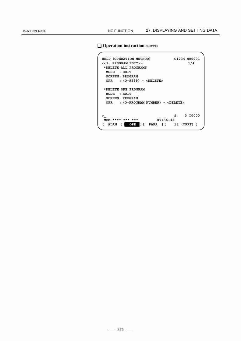
B–63522EN/03 27. DISPLAYING AND SETTING DATANC FUNCTION
375
� Operation instruction screen
HELP (OPERATION METHOD) O1234 N00001<<1. PROGRAM EDIT>> 1/4 *DELETE ALL PROGRAMS MODE : EDIT SCREEN: PROGRAM OPR : (O–9999) – <DELETE>
*DELETE ONE PROGRAM MODE : EDIT SCREEN: PROGRAM OPR : (O+PROGRAM NUMBER) – <DELETE>
>_ S 0 T0000 MEM **** *** *** 09:36:48[ ALAM ][ OPR ][ PARA ][ ][ (OPRT) ]

27. DISPLAYING AND SETTING DATA B–63522EN/03NC FUNCTION
376
A data protection key can be installed on the machine side for protectionof various NC data. The following four input signals are offered,according to type of data to be protected.
KEY 1Allows input of tool compensation amount and work zero point offsetamount.
KEY 2Allows setting data input and macro variable input.
KEY 3Allows part program input and editing.
KEY 4Allows PMC data (counter, data table) input.
This function displays a history of the key and signal operations,performed by the operator, upon the occurrence of a failure or alarm. Thehistory can also be displayed for previously generated alarms.The following history data is recorded :
MDI key/soft key operation sequences Example : A to Z, <POS>, <PAGE↑>, [SF1]
On/off status transitions of selected input and output signalsExample : G0000.7↑, SBK↑
NC alarm informationExample : P/S0010
Time (date, time) stampExample : 01/04/10
09:27:55
The history data can be output to an input/output device, connected viathe reader/punch interface. Previously output history data can be inputfrom an input/output device.
When a machining program is executed, the machining time of the mainprogram is displayed on the program machining time display screen. Themachining times of up to ten main programs are displayed inhour/minutes/seconds. When more than ten programs are executed, datafor the oldest programs is discarded.
27.12DATA PROTECTION KEY
27.13DISPLAYINGOPERATION HISTORY
27.14MACHINING TIME STAMP FUNCTION
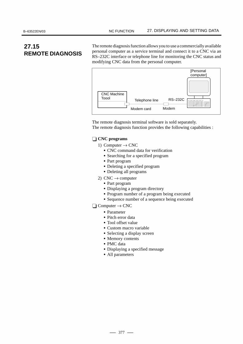
B–63522EN/03 27. DISPLAYING AND SETTING DATANC FUNCTION
377
The remote diagnosis function allows you to use a commercially availablepersonal computer as a service terminal and connect it to a CNC via anRS–232C interface or telephone line for monitoring the CNC status andmodifying CNC data from the personal computer.
CNC MachineToool
Modem card
Telephone line
Modem
RS–232C
[Personalcomputer]
The remote diagnosis terminal software is sold separately.The remote diagnosis function provides the following capabilities :
� CNC programs1) Computer → CNC
� CNC command data for verification� Searching for a specified program� Part program� Deleting a specified program� Deleting all programs
2) CNC → computer� Part program� Displaying a program directory� Program number of a program being executed� Sequence number of a sequence being executed
� Computer → CNC
� Parameter� Pitch error data� Tool offset value� Custom macro variable� Selecting a display screen� Memory contents� PMC data� Displaying a specified message� All parameters
27.15REMOTE DIAGNOSIS

27. DISPLAYING AND SETTING DATA B–63522EN/03NC FUNCTION
378
� CNC → computer
� Alarm information� Machine position� Absolute position� Skip position� Servo delay� Acceleration/deceleration delay� Diagnosis� Parameter� Tool life management data� Display screen status� Modal information� Pitch error data� Tool offset value� Custom macro variable� Memory contents� Ladder program� Actual feedrate� Status� A/D conversion� PMC data� Screen character data� Printed circuit board information� Ladder title� Series and edition of PMC/ladder� All parameters
� File function selection
� Listing files� Referring a file� Deleting a file� Copying a file � Renaming a file� Linking a file� Changing the current directory� Creating a directory� Deleting a directory
NOTE1 An arrow “→” indicates the direction of data flow.2 For the 160i/180i/210i/160is/180is/210is, the remote
diagnosis relay function must be started. For details, referto the Readme files on the Open CNC Drivers Disk(A02B–0207–K792) and in the Open CNC StandardApplication Library (A02B–0207–K736).

B–63522EN/03 27. DISPLAYING AND SETTING DATANC FUNCTION
379
CNC programs stored in memory can be grouped according to theirnames, thus enabling the listing and output of CNC programs on agroup–by–group basis.To assign multiple CNC programs to a single group, assign names to thoseprograms, beginning each name with the same character string. Bysearching through all the program names for a specified character string,the program numbers and names of all programs having names includingthat string are listed.The CNC programs within a specified group can also be output.
� Group–unit program list screen displayed when a search is madefor ”GEAR–1000*”
PROGRAM DIRECTORY(GROUP) O0001 N00010
PROGRAM(NUM.) MEMORY’CHAR.) –USED: 60 3321 –FREE: 2 429 O0020 (GEAR–1000 MAIN) O0040 (GEAR–1000 SUB–1) O0200 (GEAR–1000 SUB–2) O2000 (GEAR–1000 SUB–3)
> EDIT **** *** *** *** 16:53:25[ PRGRM ][ DIR ][ ][ ][ (OPRT) ]
When screen indication isn’t necessary, the life of the back light for LCDcan be put off by turning off the back light.The screen can be cleared by pressing specific keys. It is also possible tospecify the automatic clearing of the screen if no keys are pressed duringa period specified with a parameter. (This cannot be performed for160i/180i/210i/160is/180is/210is.)But, the life of the back light may be contracted all the more when theclearing of screen and re–indication of screen are repeated beyond thenecessity.This effect can be expected when a screen is cleared for more than onehour.
27.16DIRECTORY DISPLAYAND PUNCH FOR ASPECIFIED GROUP
27.17CLEARING THE SCREEN

27. DISPLAYING AND SETTING DATA B–63522EN/03NC FUNCTION
380
The periodic maintenance screen shows the current statuses of thoseconsumables that require periodic replacement (backup battery, LCDbacklight, touch pad, etc.). An item whose service life has expired isindicated by the machine run time or the like.
PERIODICAL MAINTENANCE O0001 N12345(STATUS)
ITEM NAME REMAIN 01 BATTERY FOR CONTROLLER 0H @ 02 BATTERY FOR PULSECODER 5000H 03 LCD BACK LIGHT 10000H @ 04 COOLANT 720H 05
0607080910
>_EDIT **** *** *** 19:27:05[ ][MAINTE ][ ][ ][(OPRT) ]
A pen input device/touch pad, manufactured by Fujitsu Limited, is usedon the LCD display as follows:
(1)The soft keys below the 10.4–inch color LCD/MDI panel (F0 to F9,FR, and FL) are replaced by the soft keys on the touch panel.
(2)The cursor displayed on the 10.4–inch color LCD is controlled fromthe touch panel.
(3)A touch–panel–type software machine operator’s panel, realized by Cexecutor, can be used.
(4)A touch–panel–type calculator, realized by C executor, can be used.
(5)A C executor application program can be created by using the touchpanel.
When this interface is supported, an external touch panel supporting theSNP–X protocol can be attached to the FANUC Series 16i/18i/21i(described just as the FS16 hereinafter).With the external touch panel which has functions equivalent to themachine operator’s panel, the PMC–controlled signals (input signals (X),output signals (Y), internal relays (R), keep relays (K), data tables (D),timers (T), and counters (C)) can be read and written.The external touch panel features a plotting capability. The user canperform plotting and address (signal) assignment freely. For example,when a screen to which data table settings are assigned is created, data inthe data table can be set using switches on the screen.
27.18PERIODICMAINTENANCESCREEN
27.19TOUCH PANEL
27.20EXTERNAL TOUCH PANEL INTERFACE

B–63522EN/03 27. DISPLAYING AND SETTING DATANC FUNCTION
381
The history of the maintenance carried out by FANUC service personneland machine tool builder can be recorded via the screen. The screen hasthe following features:
Alphabetical characters can be input from MDI. (Half–size kana canbe input only when Japanese display is selected.)
The recording screen can be scrolled, line by line.
Edited maintenance information can be read and punched.
Data can be stored into flash ROM.
Full–size (shift JIS) codes can be displayed. (Input codes are readonly.)
When the VGA graphic control function is supported, the VGA screencolors can be set on the color setting screen.
1(PARAMETER)
BLUERED
[1] �
2 �
3 �
4 �
5 �
6 �
7 �
8 �
9 �
10 �
11 �
12 �
13 �
14 �
15 �
08 00 00
[MEM **** *** ***|***|12:34:56| ]
+
COLORING O0000 N00000
�ALARM
�TITLE �SOFT KEY 1
�INPUT KEY�STATUS�CURSOR
�RESTART NO.
�SUB TITLE�ABSOLUTE ORDER
�SOFT KEY 2
�DATA�TIME
�SELECT WINDOW BAR
�NONE
�TITLE BAR �INPUT BAR
�WINDOW BACKGROUND
�LIGHT
�ALTER POSSIBLE DATA
�SHADOW
�BACKGROUND
GREEN
OPRTCOLOR
�O/N NO.
COLOR SELECT NO.
27.21MAINTENANCEINFORMATIONSCREEN
27.22COLOR SETTING SCREEN

27. DISPLAYING AND SETTING DATA B–63522EN/03NC FUNCTION
382
Some operators may find the LCD difficult to read, depending on their eyelevel relative to the display. To make a monochrome LCD easier to read,the contrast can be adjusted.
SETTING(HANDY)
PARAMETER WRITE =1(0:DISABLE 1:ENABLE)TV CHECK =0(0:OFF 1:ON)PUNCH CODE =0(0:EIA 1:ISO)INPUT UNIT =0(O:MM 1:INCH)I/O CHANNEL =0(0–3:CHANNEL NO.)SEQUENCE NO. =0(0:OFF 1:ON)TAPE FORMAT =0(0:NO CNV 1:F15)SEQUENCE STOP = 0(PROGRAM NO.)SEQUENCE STOP = 0(SEQUENCE NO.)
CONTRAST (+=[ON:1] –=[OFF:0])> MDI **** *** *** BAT 00:00:00[NO.SRH ][ ON:1 ][ OFF:0 ][+INPUT ][ INPUT ]
27.23CONTRASTADJUSTMENTSCREEN

B–63522EN/03 27. DISPLAYING AND SETTING DATANC FUNCTION
383
This section describes the screen used to set parameters for the embeddedEthernet function.
NOTEWith the series 20i–B, the “FACTOLINK function” and“DNC1/Ethernet function” are not operated. The“FOCAS1/Ethernet function” can communicate only withthe following application software products. The functioncannot communicate with any application software createdby users using “FANUC Open CNC FOCAS1/EthernetCNC/PMC Data Window Library.”– Servo Guide– FANUC LADDER–III– Machine Remote Diagnosis Package
On the Ethernet parameter setting screen, set the parameters for operatingthe FACTOLINK function.
Display
1 Place the CNC in the MDI mode.
2 Press the function key SYSTEM .
3 Press the continuous menu key at the right end of the soft key display.
4 Press the [ETHPRM] soft key. The Ethernet parameter setting screenappears. The Ethernet functions currently available are displayed.
27.24SETTING THEEMBEDDEDETHERNETFUNCTION
27.24.1FACTOLINK ParameterSetting Screen
Procedure
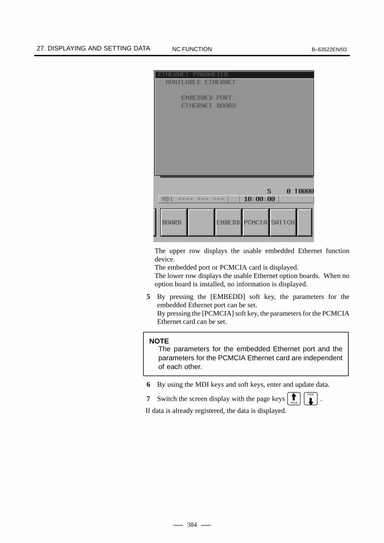
27. DISPLAYING AND SETTING DATA B–63522EN/03NC FUNCTION
384
The upper row displays the usable embedded Ethernet functiondevice.The embedded port or PCMCIA card is displayed.The lower row displays the usable Ethernet option boards. When nooption board is installed, no information is displayed.
5 By pressing the [EMBEDD] soft key, the parameters for theembedded Ethernet port can be set.By pressing the [PCMCIA] soft key, the parameters for the PCMCIAEthernet card can be set.
NOTEThe parameters for the embedded Ethernet port and theparameters for the PCMCIA Ethernet card are independentof each other.
6 By using the MDI keys and soft keys, enter and update data.
7 Switch the screen display with the page keys PAGE
PAGE
.
If data is already registered, the data is displayed.

B–63522EN/03 27. DISPLAYING AND SETTING DATANC FUNCTION
385
Display item and setting items
The item related to the embedded Ethernet function is displayed.
Item Description
MAC ADDRESS Embedded Ethernet MAC address
Display item related tothe embedded Ethernetfunction

27. DISPLAYING AND SETTING DATA B–63522EN/03NC FUNCTION
386
Set the TCP/IP–related items of the embedded Ethernet.
Item Description
IP ADDRESS Specify the IP address of the embedded Ethernet.(Example of specification format: ”192.168.1.1”)
SUBNET MASK Specify a mask address for the IP addresses of the net-work.(Example of specification format: ”255.255.255.0”)
ROUTER IP ADDRESS
Specify the IP address of the router.Specify this item when the network contains a router.(Example of specification format: ”192.168.1.254”)
Set the items related to the host computer with which the FACTOLINKserver operates.
Item Description
IP ADDRESS Specify the IP address of a personal computer to be ac-cessed by the FACTOLINK function.(Example of specification format: ”192.168.1.100”)
PORT NUMBER Specify a port number to be used with the FACTOLINKfunction. The valid input range is 5001 to 65535.A specified port number must match ”ocsnc” of the ”ser-vices” file of the personal computer.For details, refer to ” FANUC FACTOLINK Script FunctionOPERATOR’S MANUAL (B–75054EN)”.
On the Ethernet parameter setting screen, set the parameters for operatingthe FOCAS1/Ethernet function.
NOTEWith the series 20i–B, the “FOCAS1/Ethernet function” cancommunicate only with the following application softwareproducts. The function cannot communicate with anyapplication software created by users using “FANUC OpenCNC FOCAS1/Ethernet CNC/PMC Data Window Library.”– Servo Guide– FANUC LADDER–III– Machine Remote Diagnosis Package
Embedded EthernetTCP/IP setting items
FACTOLINK settingitems
27.24.2FOCAS1/EthernetParameter SettingScreen

B–63522EN/03 27. DISPLAYING AND SETTING DATANC FUNCTION
387
Display
1 Place the CNC in the MDI mode.
2 Press the function key SYSTEM .
3 Press the continuous menu key at the right end of the soft key display.
4 Press the [ETHPRM] soft key. The Ethernet parameter setting screenappears. The Ethernet functions currently available are displayed.
The upper row displays the usable embedded Ethernet functiondevice.The embedded port or PCMCIA card is displayed.The lower row displays the usable Ethernet option boards. When nooption board is installed, no information is displayed.
5 By pressing the [EMBEDD] soft key, the parameters for theembedded Ethernet port can be set.By pressing the [PCMCIA] soft key, the parameters for the PCMCIAEthernet card can be set.
NOTEThe parameters for the embedded Ethernet port and theparameters for the PCMCIA Ethernet card are independentof each other.
���������

27. DISPLAYING AND SETTING DATA B–63522EN/03NC FUNCTION
388
6 By using the MDI keys and soft keys, enter and update data.
7 Switch the screen display with the page keys PAGE
PAGE
.
If data is already registered, the data is displayed.

B–63522EN/03 27. DISPLAYING AND SETTING DATANC FUNCTION
389
Display item and setting items
The item related to the embedded Ethernet function is displayed.
Item Description
MAC ADDRESS Embedded Ethernet MAC address
Set the TCP/IP–related items of the embedded Ethernet.
Item Description
IP ADDRESS Specify the IP address of the embedded Ethernet.(Example of specification format: ”192.168.1.1”)
SUBNET MASK Specify a mask address for the IP addresses of the net-work.(Example of specification format: ”255.255.255.0”)
ROUTER IP ADDRESS
Specify the IP address of the router.Specify this item when the network contains a router.(Example of specification format: ”192.168.1.254”)
Set the items related to the FOCAS1/Ethernet function.
Item Description
PORT NUMBER(TCP)
Specify a port number to be used with the FOCAS1/Ether-net function. The valid input range is 5001 to 65535.When connecting to FANUC CIMPLICITY i CELL, refer to“FANUC CIMPLICITY i CELL OPERATOR’S MANUAL(B–75074EN)”.
PORT NUMBER(UDP)
Set this item when connecting to FANUC CIMPLICITY iCELL.Specify a UDP port number for transmitting UDP broad-cast data.The valid input range is 5001 to 65535.For details, refer to ”FANUC CIMPLICITY i CELL OPERA-TOR’S MANUAL (B–75074EN)”.Set 0 when using the FOCAS1/Ethernet function or whentransmitting no UDP broadcast data.
TIME INTERVAL(NOTE 1)
Set this item when connecting to FANUC CIMPLICITY iCELL.Specify a time interval at which UDP broadcast data istransmitted as specified by the above UDP port number.The unit is 10 ms. The valid input range is 10 to 65535.This means that a value less than 100 ms cannot be spe-cified.Set 0 when using the FOCAS1/Ethernet function or whentransmitting no UDP broadcast data.Example)100: Broadcast data is transmitted at intervals of one se-cond [1000 ms] (= 100 � 10).
Display item related tothe embedded Ethernetfunction
Embedded EthernetTCP/IP setting items
FOCAS1/Ethernet settingitems

27. DISPLAYING AND SETTING DATA B–63522EN/03NC FUNCTION
390
NOTE1 When a small value is set for the item of time interval,
communication load increases, and the performance of thenetwork can be adversely affected.
2 The parameters for the PCMCIA Ethernet card are set to thefollowing default values before shipment:IP address: 192.168.1.1Subnet mask: 255.255.255.0Router IP address: NoneTCP port number: 8193UDP port number: 0Time interval: 0
On the Ethernet parameter setting screen, set the parameters for operatingthe FTP file transfer function.
NOTEThe FTP file transfer function is usable with the controlsoftware for the embedded Ethernet function series 656Aedition 02 or later and series 656V edition 01 or later.
27.24.3FTP File TransferParameter SettingScreen

B–63522EN/03 27. DISPLAYING AND SETTING DATANC FUNCTION
391
Display
1 Place the CNC in the MDI mode.
2 Press the function key SYSTEM .
3 Press the continuous menu key at the right end of the soft key display.4 Press the [ETHPRM] soft key. The Ethernet parameter setting screen
appears. The Ethernet functions currently available are displayed.
The upper row displays the usable embedded Ethernet functiondevice.The embedded port or PCMCIA card is displayed.The lower row displays the usable Ethernet option boards. When nooption board is installed, no information is displayed.
5 By pressing the [EMBEDD] soft key, the parameters for theembedded Ethernet port can be set.By pressing the [PCMCIA] soft key, the parameters for the PCMCIAEthernet card can be set.
NOTEThe parameters for the embedded Ethernet port and theparameters for the PCMCIA Ethernet card are independentof each other.
���������

27. DISPLAYING AND SETTING DATA B–63522EN/03NC FUNCTION
392
6 By using the MDI keys and soft keys, enter and update data.
7 Switch the screen display with the page keys PAGE
PAGE
.
If data is already registered, the data is displayed.
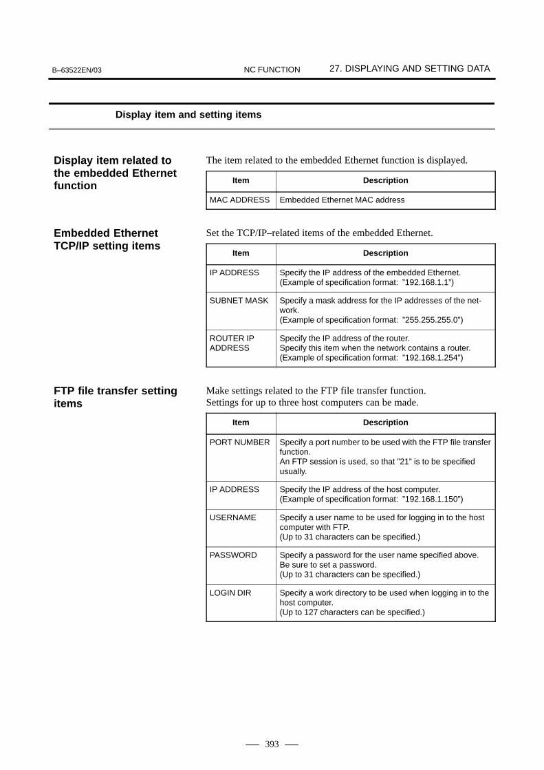
B–63522EN/03 27. DISPLAYING AND SETTING DATANC FUNCTION
393
Display item and setting items
The item related to the embedded Ethernet function is displayed.
Item Description
MAC ADDRESS Embedded Ethernet MAC address
Set the TCP/IP–related items of the embedded Ethernet.
Item Description
IP ADDRESS Specify the IP address of the embedded Ethernet.(Example of specification format: ”192.168.1.1”)
SUBNET MASK Specify a mask address for the IP addresses of the net-work.(Example of specification format: ”255.255.255.0”)
ROUTER IP ADDRESS
Specify the IP address of the router.Specify this item when the network contains a router.(Example of specification format: ”192.168.1.254”)
Make settings related to the FTP file transfer function.Settings for up to three host computers can be made.
Item Description
PORT NUMBER Specify a port number to be used with the FTP file transferfunction.An FTP session is used, so that ”21” is to be specifiedusually.
IP ADDRESS Specify the IP address of the host computer.(Example of specification format: ”192.168.1.150”)
USERNAME Specify a user name to be used for logging in to the hostcomputer with FTP.(Up to 31 characters can be specified.)
PASSWORD Specify a password for the user name specified above.Be sure to set a password.(Up to 31 characters can be specified.)
LOGIN DIR Specify a work directory to be used when logging in to thehost computer.(Up to 127 characters can be specified.)
Display item related tothe embedded Ethernetfunction
Embedded EthernetTCP/IP setting items
FTP file transfer settingitems

27. DISPLAYING AND SETTING DATA B–63522EN/03NC FUNCTION
394
When the αi servo or αi spindle is connected, if each of the units (motoror amplifier) actually connected it has ID information, the ID informationcan be read and displayed on the CNC screen.
If no servo information is recorded, servo information is automaticallystored in flash ROM. On the screen, if there is a difference between theservo information in flash ROM and the actual servo information, thecorresponding items are preceded by *, as shown below. This allowsyou to determine whether the configuration of connected units ischanged. At this time, the servo information is read from flash ROM.
The servo information recorded or stored in flash ROM can also be edited.See Chapter 9 ”Digital Servo” in the Maintenance Manual (B–63525EN).
27.25ID INFORMATIONSCREEN
Overview
27.25.1αi Servo InformationScreen
Displaying the servo IDscreen
Editing the servo IDscreen

B–63522EN/03 27. DISPLAYING AND SETTING DATANC FUNCTION
395
If no spindle information is recorded, spindle information isautomatically stored in flash ROM. On the screen, if there is adifference between the spindle information in flash ROM and theactual spindle information, the corresponding items are preceded by*, as shown below. This allows you to determine whether theconfiguration of connected units is changed. At this time, the spindleinformation is read from flash ROM.
The spindle information recorded or stored in flash ROM can also beedited.See Chapter 10 ”Spindle” in the Maintenance Manual (B–63525EN).
27.25.2αi Spindle InformationScreen
Displaying the spindle IDscreen
Editing the spindle IDscreen

28.PART PROGRAM STORAGE AND EDITING B–63522EN/03NC FUNCTION
396
28 PART PROGRAM STORAGE AND EDITING

28. PART PROGRAM STORAGE AND EDITINGB–63522EN/03 NC FUNCTION
397
The following part program storage and editing is possible
� Program tape registration to the memory� Single program registration � Multi program tape registration
� Program input via MDI� Program deletion
� Single program deletion � All programs deletion � Multi programs deletion by specification the range
� Program punching� Single program punching � All programs punching � Multi programs punching by specification the range
� Program editing� Change
� Word change � Change of 1-word to multi-words
� Insertion � Word insertion� Multi words, and multi blocks insertion
� Deletion� Word deletion � Deletion to EOB � Deletion to the specified word
� Part program collationCollation of program stored in the memory and program on the tapecan be done.
� Sequence number automatic insertionThe sequence number, where a certain increment value is added to thesequence number of the previous block can be automatically insertedat the head of each block in preparation of programs by the partprogram editing. The initial value of sequence number and a certain increment amountcan be set.
Part program storage and editing can be done during machining. Thesame functions as foreground editing can be performed.However, it is not possible to delete all programs at one time.
28.1FOREGROUNDEDITING
28.2BACKGROUNDEDITING

28.PART PROGRAM STORAGE AND EDITING B–63522EN/03NC FUNCTION
398
The following editing is possible.
� Conversion� Address conversion
An address in the program can be converted to another address. Forexample address X in the program can be converted to address Y.
� Word conversion A word in the program can be converted to another word. Forexample, a programmed M03 can be converted to M04.
� Program copyA part or all of a program can be copied to make a new program.
� Program moveA part or all of a program can be moved to make a new program.
� Program mergeA new program can be created by merging two programs.
� Editing in the key–in bufferA word starting from the current cursor position or words up to an EOBcan be copied and moved from the program to key–in buffer. Inaddition, characters input in the key–in buffer can be edited.
Number of registered programs can be selected from the following: 63, 125, 200, 400, or 1000.
The following part program storage length can be selected:10, 20, 40, 80, 160, 320, 640, 1280, 2560, or 5120 m.
Program can be prepared by storing machine position obtained by manualoperation in the memory as program position. Data other than thecoordinate value (M codes, G codes, feed rates, etc.) are registered in thememory by the same operation as part program storage and editing.
Part program registration and punch can be commanded externally.
� Program registrationA part program can be registered in memory through the connectedinput device for background editing using the external read startsignal.
� Program punch A part program can be punched through the connected output devicefor background editing using the external punch start signal.
28.3EXPANDED PART PROGRAM EDITING
28.4NUMBER OF REGISTEREDPROGRAMS
28.5PART PROGRAM STORAGE LENGTH
28.6PLAY BACK
28.7EXTERNALCONTROL OF I/O DEVICE
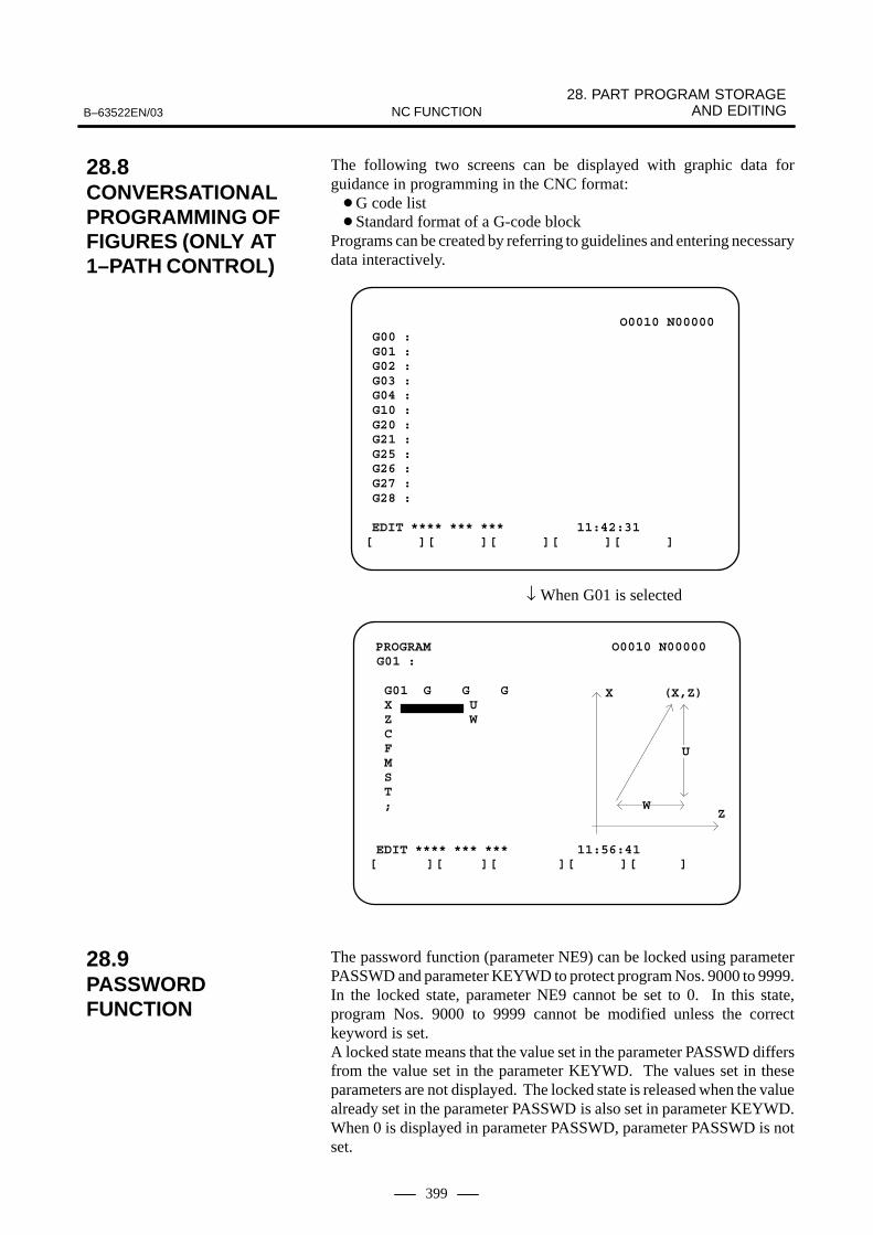
28. PART PROGRAM STORAGE AND EDITINGB–63522EN/03 NC FUNCTION
399
The following two screens can be displayed with graphic data forguidance in programming in the CNC format:�G code list� Standard format of a G-code block
Programs can be created by referring to guidelines and entering necessarydata interactively.
O0010 N00000 G00 : G01 : G02 : G03 : G04 : G10 : G20 : G21 : G25 : G26 : G27 : G28 : EDIT **** *** *** 11:42:31[ ][ ][ ][ ][ ]
↓ When G01 is selected
PROGRAM O0010 N00000 G01 : G01 G G G X U Z W C F M S T ; EDIT **** *** *** 11:56:41[ ][ ][ ][ ][ ]
X
ZW
U
(X,Z)
The password function (parameter NE9) can be locked using parameterPASSWD and parameter KEYWD to protect program Nos. 9000 to 9999.In the locked state, parameter NE9 cannot be set to 0. In this state,program Nos. 9000 to 9999 cannot be modified unless the correctkeyword is set.A locked state means that the value set in the parameter PASSWD differsfrom the value set in the parameter KEYWD. The values set in theseparameters are not displayed. The locked state is released when the valuealready set in the parameter PASSWD is also set in parameter KEYWD.When 0 is displayed in parameter PASSWD, parameter PASSWD is notset.
28.8CONVERSATIONALPROGRAMMING OF FIGURES (ONLY AT 1–PATH CONTROL)
28.9PASSWORDFUNCTION

29. DIAGNOSIS FUNCTIONS B–63522EN/03NC FUNCTION
400
29 DIAGNOSIS FUNCTIONS

B–63522EN/03 29. DIAGNOSIS FUNCTIONSNC FUNCTION
401
The CNC checks the following itself.
� Abnormality of detection system
� Abnormality of position control unit
� Abnormality of servo system
� Overheat
� Abnormality of CPU
� Abnormality of ROM
� Abnormality of RAM
� Abnormality in data transfer between MDI
� Abnormality of part program storage memory
� Abnormality in tape reader read function
� Abnormality in data transfer between PMC
The CNC also checks other items.
Input/output signals from PMC to CNC, or vice versa, and inner statusof the CNC can be displayed.
29.1SELF DIAGNOSIS FUNCTIONS

30. DATA INPUT/OUTPUT B–63522EN/03NC FUNCTION
402
30 DATA INPUT/OUTPUT
The NC has the following input/output data. These data are input/output via various input/output devices asCRT/MDI, tape reader, etc.
� Input dataThe NC has the following input data.� Part program� Tool compensation amount and Work zero point offset value � Tool life management data � Setting data� Custom macro common variable� Pitch error compensation data� Parameters
� Output dataThe NC has the following output data. � Part program� Tool compensation amount and work zero point offset value � Setting data� Custom macro common variable � Pitch error compensation data� Parameters

B–63522EN/03 30. DATA INPUT/OUTPUTNC FUNCTION
403
The following can be input/output via the reader/punch interface.
� Part program registration/output
� Tool offset amount, work zero point offset amount, input/output
� Tool life management data input
� Custom macro common variable input/output
� Pitch error compensation data input/output
� Parameter punch input/output
Usually, the screen is switched according to the type of data to be inputfrom or output to an external device; for example, a parameter screen isused for parameter input/output, and a program screen is used for programinput/output. However, a single ALL I/O screen can be used to input andoutput programs, parameters, offset data, and macro variables.
30.1READER/PUNCHINTERFACES

30. DATA INPUT/OUTPUT B–63522EN/03NC FUNCTION
404
The following Input/Output devices are prepared, which are connectableto the reader/puncher interface.
When the Floppy Cassette is connected to the NC, machining programsstored in the NC can be saved on a Floppy Cassette, and machiningprograms saved in the Floppy Cassette can be transferred to the NC.
The built-in hard disk enables data to be stored and it can be connectedto the reader/puncher interface to input data to CNC. This hard disk hasa large storage capacity of approximately 50,000 m of paper tape data, soit can register maximum 1024 command programs. It can be connected to the remote buffer to achieve high-speed transfer ofmaximum 86.4 kbps.The hard disk is sealed to be continuously used under the factoryenvironment.
The FANUC Handy File is a compact multi functional input/ouput floppydisk unit for use with various types of FA equipment. Programs can betransferred or edited through operations performed directly on the HandyFile or through remote operation from connected equipment.Compared with media such as paper tape, a 3.5” floppy disk is bothcompact and durable, and eliminates noise during input/output.Programs with a total capacity of up to 1.44 MB (equivalent to about 3600m paper tape) can be saved on a single floppy disk.
By using the external program input start signal, a program can be loadedfrom an input unit into CNC memory.When an input unit such as the FANUC Handy File or FANUC FloppyCassette is being used, a file can be searched for using the workpiecenumber search signals, after which the program can be loaded into CNCmemory.
30.2INPUT/OUTPUTDEVICES
30.2.1FANUC FloppyCassette
30.2.2FANUC Program FileMate
30.2.3FANUC Handy File
30.3EXTERNALPROGRAM INPUT

B–63522EN/03 30. DATA INPUT/OUTPUTNC FUNCTION
405
Files on a memory card can be referenced, and different types of data suchas part programs, parameters, and offset data on a memory card can beinput and output in text file format.
The major functions are listed below.
� Displaying a directory of stored filesThe files stored on a memory card can be displayed on the directoryscreen.
� Searching for a file A search is made for a file on a memory card and, if found, it isdisplayed on the directory screen.
� Reading a fileText–format files can be read from a memory card.
� Writing a fileData such as part programs can be stored to a memory card in text fileformat.
� Deleting a file A file can be selected and deleted from a memory card.
CNC
Writing a file
Reading a file
Displaying a directorySearching fora file
Deleting a file
Memory card
NOTEFor the 160i/180i/210i/160is/180is/210is, use the CNCscreen display function.
30.4DATA INPUT/OUTPUTUSING A MEMORY CARD

30. DATA INPUT/OUTPUT B–63522EN/03NC FUNCTION
406
Screen information displayed on the CNC can be output to a memory cardin a bit–mapped format. In this case, however, only still pictureinformation can be output. Bit–mapped data created by this function canbe displayed on a Windows personal computer and so forth.To take a hard copy of a screen, set a memory card in the CNC, then hold
down the SHIFT key for five seconds or set hard copy start signal HDREQ
(G67 #7) to 1. In several seconds to several tens seconds until hard copyoperation completes, a still picture is displayed on the screen.The number of colors of a created bit–mapped format file depends on thedisplay control card, LCD hardware, and the display mode of the CNCscreen. The relationships are listed in Table 30.5 (a).
Table 30.5 (a) Number of colors of bit–mapped format files created by screen hard copy
LCD hardware
CNC screendisplay mode
Number of colors displayed
on CNC
Number of colors in BMP
dataRemarks
VGA
Monochrome — 2 colors 2 colorsMonochrome gradation is not sup-ported.
VGAcard
Color
VGA compatible
mode
Characters: 16 colors
Graphic: 16 colors
��������� �
���� ����
�256 colors��������� �
���� ���
�16 colors
Ordinary CNC screen is displayed.If parameter No.3301#0 is 1, colorsmay differ from the screen display.
VGA mode 256 colors 256 colors Screen that can be prepared using Cexecutor.
Table 30.5 (b) shows the data sizes of bit–mapped format files.
Table 30.5 (b) Number of colors and data size of bit–mapped format files
Number of colors in bit map File size (bytes)
Monochrome (2 colors) 38,462
Color (16 colors) 153,718
Color (256 colors) 308,278
NOTEFor the 160i/180i/210i/160is/180is/210is, this function isdisabled.
30.5SCREEN HARD COPY

B–63522EN/03 30. DATA INPUT/OUTPUTNC FUNCTION
407
DNC1 is a network originally developed by FANUC. Personal computerFA supports a connection mode called mode 1 of DNC1. This modeallows multi–point communication in which the personal computerfunctions as a primary station to control multiple NCs. In personalcomputer FA, up to 16 NCs can be connected to a single personalcomputer. For details, refer to ”Personal Computer FA System Operator’sManual (B–75044EN).”
DNC1 board
DNC1 board(for NC)
NC
Optical fi-ber cable
COP1
Personalcomputer
Opticaladapter B
Terminatingresistor unitTap
Metalcable
When three NCs and a personal computer are connected via optical adapter B
User applications created using the FA library of personal computer FAcan perform the following processing:
� NC program file downloading started from the personal computer
� NC program file uploading started from the personal computer
� External reset
� Selection and deletion of NC programs
� Read of NC directory information
� Read of alarm information
� Read and write of tool offset values
� Read and write of custom macro variables
� Read of tool life management data
� Read and write of PMC data
� Read of NC identification information
� Read and write of NC parameters
� Notification of the start and end of NC program file downloading anduploading started by an NC
30.6DNC1 CONTROL
Connection example

30. DATA INPUT/OUTPUT B–63522EN/03NC FUNCTION
408
The FANUC DNC2 is a communication protocol enabling datatransmission between the FANUC CNC unit and a personal computer byconnecting them via the RS–232C interface.
The FANUC DNC2 has the following features:
(1)This protocol is based on the communication protocol LSV2 used bysome CNC manufacturers in Europe, so that software can easily beestablished even with a personal computer.The RS–232C interface is used to connect a personal computer withthe FANUC CNC. The RS–422 interface can also be used to improvethe transmission rate.
(2)This protocol is used for one–to–one (point–to–point) communicationbetween one FANUC CNC unit and one personal computer.The protocol cannot provide multi–point communication between onepersonal computer and more than one CNC unit.
PersonalComputer CNC
Command / Response
Response / Command
30.7DNC2 CONTROL (ONLY AT 1–PATH CONTROL)

B–63522EN/03 30. DATA INPUT/OUTPUTNC FUNCTION
409
When an option board (the Ethernet board or data server board) is used,the following Ethernet functions are available:
When the Ethernet board is used– FOCAS1/Ethernet function– DNC1/Ethernet function– FACTOLINK function
When the data server board is used– FOCAS1/Ethernet function– DNC1/Ethernet function– FACTOLINK function– Data server function
These functions can be used together at the same time.
Personalcomputer
Hub
Operation from personal computer
Operation from NC
Operation from NC
ATA flash card
Hard disk
NOTE1 An Ethernet board and a data server board cannot be
installed at the same time.2 With the series 20i–B, the “FACTOLINK function” and
”DNC1/Ethernet function” are not operated. The“FOCAS1/Ethernet function” can communicate only withthe following application software products. The functioncannot communicate with any application software createdby users using “FANUC Open CNC FOCAS1/EthernetCNC/PMC Data Window Library.”– Servo Guide– FANUC LADDER–III– Machine Remote Diagnosis Package
3 The Series 20i–B does not support data server boards.
30.8ETHERNETFUNCTION (OPTION BOARD)

30. DATA INPUT/OUTPUT B–63522EN/03NC FUNCTION
410
The FOCAS1/Ethernet function allows remote control and monitoring ofCNCs from the personal computer. This function can transfer a widerrange of NC data than the DNC1/Ethernet function.For details, refer to ”Ethernet Board/DATA SERVER Board Operator’sManual (B–63354EN)” and ”FANUC Open CNC FOCAS1/EthernetCNC/PMC Data Window Library Description.”
The following NC data can be transferred by operation on the personalcomputer:
� Data related to controlled axes and spindles� Absolute position, relative position, machine position� Remaining travel distance� Actual feedrate
� NC program� Directory information in part program storage� NC file data
� Parameters� Tool offset values� Custom macro variables� Workpiece zero point offset values� Settings� P code macro variables� Pitch error compensation data
� Tool life management data� History data
� Operation history data� Alarm history data
� Data related to servo systems and spindles� Data related to profile diagnosis� Modal data� Diagnostic data� A/D conversion data� Alarm information� NC system identification information� PMC data
� Addresses G, F, Y, X, A, R, T, K, C, D� Extended hold type data
The following operations can be performed by operation on the personalcomputer:
� Selecting NC programs� Deleting NC programs� External reset
The following operation can be performed by operation on the personalcomputer:
� DNC operation
30.8.1FOCAS1/EthernetFunction
NC data transfer
Remote control
Operation

B–63522EN/03 30. DATA INPUT/OUTPUTNC FUNCTION
411
The DNC1/Ethernet function allows remote control and monitoring ofCNCs from the personal computer. This function provides a softwarelibrary having a simpler function call format than the FOCAS1/Ethernetfunction.For details, refer to ”Ethernet Board/DATA SERVER Board Operator’sManual (B–63354EN)” and ”FANUC Personal Computer FA SystemWindows NT Version Operator’s Manual (B–75044EN).”
The following NC data can be transferred by operation on the personalcomputer:
� NC programs
� Directory information in part program storage
� NC file data
� Parameters
� Tool offset values
� Custom macro variables
� Alarm information
� NC system identification information
� PMC data
� Addresses G, F, Y, X, A, R, T, K, C, D
The following operations can be performed by operation on the personalcomputer:
� Selecting NC programs
� Deleting NC programs
� External reset
The following operation can be performed by operation on the personalcomputer:
� DNC operation
30.8.2DNC1/EthernetFunction
NC data transfer
Remote control
Operation

30. DATA INPUT/OUTPUT B–63522EN/03NC FUNCTION
412
With the FACTOLLINK function, the user can operate a CNC to displayinformation such as operation instructions on the CNC screen and transferNC data.For details, refer to ”Ethernet Board/DATA SERVER Board Operator’sManual (B–63354EN)” and ”FANUC FACTOLINK Script FunctionOperator’s Manual (B–75054EN).”
Information created on the personal computer such as operationinstructions can be displayed on the NC screen by operation on an NC.
The following NC data can be transferred by operation on the personalcomputer:
� NC programs
� NC file data
� Parameters
� Ladder programs
� C executor execution form
� Macro executor execution form
� NC system files
� PMC data
� Addresses T, K, C, D
The machine status can be posted automatically to the personal computer.
Personal computer
Screen information NC data
Machine status NC data
CNC screen
Troubleshooting guidance
Lubrication of guide roller
Ethernet
30.8.3FACTOLINK Function
Screen display
NC data transfer
Logging

B–63522EN/03 30. DATA INPUT/OUTPUTNC FUNCTION
413
The data server function can perform NC data transfer and DNC operationby using FTP.The data server function operates mainly as an FTP client. It also operatesas an FTP server.The data server function uses the ATA flash card included in (attached to)the data server board as an NC data storage area. For details, refer to”Ethernet Board/DATA SERVER Board Operator’s Manual(B–63354EN).”
By operation on an NC, this function is operated as an FTP client andprovides the following services:
� GET
� MGET
� PUT
� MPUT
� DIR
� DEL
By operation on the personal computer, the function is operated as an FTPserver and provides the following services:
� GET
� MGET
� PUT
� MPUT
� DIR
� DEL
The following NC data can be transferred by operation on an NC:
� NC programs
� NC file data
� Parameters
� Tool offset values
� Custom macro variables
� Workpiece zero point offset values
� Pitch error compensation data
� M code group (for the Series 16i/18i–A only)
� History data
� Operation history data
30.8.4Data Server Function
NC data transfer(between the personalcomputer and the harddisk on the data serverboard] <FTP client>
NC data transfer[between the personalcomputer and the harddisk on the data serverboard] <FTP server>
NC data transfer[between the hard diskon the data server boardand part programstorage]

30. DATA INPUT/OUTPUT B–63522EN/03NC FUNCTION
414
The following operations can be performed by operation on an NC:
� DNC operation
� DNC operation by subprogram call (M198)
The following operations can be performed by operation on an NC:
� DNC operation
� DNC operation by subprogram call (M198)
Hard disk management can be performed by operation on an NC.
� Hard disk formatting
� Hard disk check
� Display of a list of files on the hard disk
Operation [between thehard disk on the dataserver board and partprogram storage]
Operation [between thepersonal computer andpart program storage]
Hard disk management
B–63522EN/03 30. DATA INPUT/OUTPUTNC FUNCTION
415
The embedded Ethernet function can be used by selecting one of twotypes of devices: the embedded Ethernet port and PCMCIA Ethernet card.
The PCMCIA Ethernet card is to be inserted into the memory card slotto the left of the front LCD for temporary communication.
NOTE1 Use the PCMCIA Ethernet card for temporary
communication only. Do not use the PCMCIA Ethernet cardfor routine communication.
2 The PCMCIA Ethernet card is to be inserted into thememory card slot to the left of the LCD. This means thatsome part of the card is projected. When using the PCMCIAEthernet card, be careful not to damage the card by hittingthe card with an object.After using the PCMCIA Ethernet card, remove the cardimmediately to prevent the card from being damaged.
3 With Series 21i/20i/210i/210is–B, the embedded Ethernetport cannot be used.
4 As for “PCMCIA Ethernet card” to describe here, it isdescribed about the case that it was inserted into Series 16i/18i/21i/20i–B.When PCMCIA Ethernet card is inserted into Series 160i/180i/210i/160is/180is/210is–B, PCMCIA Ethernet carddoes not become embedded Ethernet.
30.9EMBEDDEDETHERNETFUNCTION
30.9.1Embedded Ethernetand PCMCIA Ethernet

30. DATA INPUT/OUTPUT B–63522EN/03NC FUNCTION
416
With the embedded Ethernet function, the following functions can beoperated:� FACTOLINK function� FOCAS1/Ethernet function� DNC1/Ethernet function� FTP file transfer function
NOTESWith the series 20i–B, the “FACTOLINK function” and“DNC1/Ethernet function” are not operated. The“FOCAS1/Ethernet function” can communicate only withthe following application software products. The functioncannot communicate with any application software createdby users using “FANUC Open CNC FOCAS1/EthernetCNC/PMC Data Window Library.”– Servo Guide– FANUC LADDER–III– Machine Remote Diagnosis Package
With the FACTOLINK function, data can be displayed on the CNCscreen, and NC data can be transferred by operations on the NC.For details, refer to ”FANUC FACTOLINK Script FunctionOPERATOR’S MANUAL (B–75054EN)”.
NOTEThe FACTOLINK function is usable with the control softwarefor the embedded Ethernet function series 656A edition 02or later and series 656V edition 01 or later.
Data created by a personal computer can be displayed on the NC screenby operations on the NC.
The following NC data can be transferred by operations on the NC:
� NC program� NC file data
� Parameter� Ladder program� C languarge executor in executable form� Macro executor in executable form� NC system file
� PMC data� Addresses T, K, C, D
Machine state information can be automatically sent to the personalcomputer.
30.9.2List of Functions
30.9.2.1FACTOLINK function
Screen display
NC data transfer
Logging

B–63522EN/03 30. DATA INPUT/OUTPUTNC FUNCTION
417
The FOCAS1/Ethernet function allows a personal computer to remotelycontrol and monitor the CNC. The FOCAS1/Ethernet function cantransfer a wider range of NC data than the DNC1/Ethernet function. Fordetails, refer to ”FANUC Open CNC FOCAS1/Ethernet CNC/PMC DataWindow Library Description”.
The following NC data can be transferred by operations on the personalcomputer:
� Data related to control axes/spindles
� Absolute position
� Relative position
� Machine position
� Remaining travel amount
� Actual speed
� NC program
� Part program storage directory information
� NC data file
� Parameter
� Tool offset value
� Custom macro variable
� Workpiece origin offset
� Setting data
� P code macro variable
� Pitch error compensation
� Tool life management data
� History data
� Operation history data
� Alarm history data
� Servo–/spindle–related data
� Data related to waveform diagnosis
� Modal data
� Diagnosis data
� A/D conversion data
� Alarm information
� NC system identification information
� PMC data
� Addresses G, F, Y, X, A, R, T, K, C, D
� Extended nonvolatile data
From the personal computer, the following operations can be performed:
� NC program selection
� NC program deletion
� External reset
30.9.2.2FOCAS1/Ethernetfunction
NC data transfer
Remote operation

30. DATA INPUT/OUTPUT B–63522EN/03NC FUNCTION
418
NOTEWith the FOCAS1/Ethernet function of the embeddedEthernet function, DNC operation cannot be performed.
The DNC1/Ethernet function allows a personal computer to remotelycontrol and monitor the CNC. The DNC1/Ethernet function providessoftware libraries in a simpler function call format when compared withthe FOCAS1/Ethernet function.For details, refer to ”FANUC Personal Computer FA System WindowsNT Version OPERATOR’S MANUAL (B–75044EN)”.
The following NC data can be transferred by operations on the personalcomputer:
� NC program
� Part program storage directory information
� NC file data
� Parameter
� Tool offset value
� Custom macro variable
� Alarm information
� NC system identification information
� PMC data
� Addresses G, F, Y, X, A, R, T, K, C, D
From the personal computer, the following operations can be performed:
� NC program selection
� NC program deletion
� External reset
NOTEWith the DNC1/Ethernet function of the embedded Ethernetfunction, DNC operation cannot be performed.
30.9.2.3DNC1/Ethernet function
NC data transfer
Remote operation

B–63522EN/03 30. DATA INPUT/OUTPUTNC FUNCTION
419
Differences between the FOCAS1/Ethernet function and DNC1/Ethernet function
Compared with the FOCAS1/Ethernet function, the DNC1/Ethernetfunction provides software libraries in a simpler function call format forfrequently used functions.

30. DATA INPUT/OUTPUT B–63522EN/03NC FUNCTION
420
The FTP file transfer function transfers files with FTP. The function canread and punch NC programs and various types of NC data.
NOTEThe FTP file transfer function is usable with the controlsoftware for the embedded Ethernet function series 656Aedition 02 or later and series 656V edition 01 or later.
The following NC data can be transferred by operations on the NC:
� NC program
� NC file data
� Parameter
� Tool offset value
� Workpiece origin offset value
� Pitch error compensation
� M code group (Series 16i/18i/160i/180i/160is/180is–B only)
� History data
� Operation history data
The table below indicates the differences between the embedded Ethernetfunction and the Ethernet function based on the option board.
Embedded Ethernet Option board
FOCAS1/Ethernet function Available Available
CNC screen display function Not available Available
DNC operation Not available Available
Data Server function Not available(NOTE 1) Available
FACTOLINK function Available Available
30.9.2.4FTP file transfer function
NC data transfer[Personal computer ��
Part program storage]
30.9.2.5Functional differencesbetween the embeddedEthernet function andthe Ethernet functionbased on the optionboard

B–63522EN/03 30. DATA INPUT/OUTPUTNC FUNCTION
421
NOTE1 The embedded Ethernet function includes the FTP file
transfer function.This function is almost equivalent to the NC data transferfunction in the FTP mode of the Data Server function of theoption board.
2 Compared with the option board, the embedded Ethernetfunction allows a smaller number of FOCAS1/Ethernetclients to be connected simultaneously.
3 Communications using the embedded Ethernet function isprocessed by the CPU of the CNC. This means that theoperation state of the CNC can affect the performance ofcommunication based on the embedded Ethernet function,and communication based on the embedded Ethernetfunction can affect the processing of the CNC.The embedded Ethernet function has lower priority thanaxis–by–axis processing such as automatic operationprocessing and manual operation. So, when automaticoperation is being performed or many controlled axes areinvolved, communication may become slower.On the contrary, the embedded Ethernet function hashigher priority over CNC screen display processing, Clanguage executor processing (excluding high–level tasks),and macro executor processing (excluding executionmacros). So, communication based on the embeddedEthernet function can decrease the performance of suchprocessing.
4 Note that when the embedded Ethernet function isconnected to an intranet that handles large volumes ofbroadcast data, for example, the processing of broadcastdata can take a longer time, resulting in a decrease inperformance of processing such as CNC screen displayprocessing.
Number of personal computersthat can be connected simulta-
neously
Number of clients that can beconnected simultaneously
Embedded Ethernet
Ethernetboard
10 clientsmaximum
10 unitsmaximum
1 unit (recom-mended)
5 clientsmaximum
Fast Ether-net board
20 clientsmaximum
20 unitsmaximum

30. DATA INPUT/OUTPUT B–63522EN/03NC FUNCTION
422
Power mate CNC programs, parameters, macro variables, and diagnostic(PMC) data are input/output using FANUC I/O Link.With FANUC I/O Link, slaves in groups 0 to 15 can be connected,enabling data input/output to and from a maximum of 16 power mateCNCs.The ordinary data input/output function based on I/O Link can only beexecuted in the foreground. When data input/output function B based onI/O Link is used, the external I/O device control function is associatedwith I/O Link so that an input/output group number and program numbercan be specified from the PMC. The external I/O device control functionoperates in the background. Therefore, when no other backgroundoperation is being performed, data can be input/output, regardless of theNC mode and the currently selected screen.
Series 16/18/21
#0KSlave (Group #0)
power mateCNC
(Group #1) (Group #15)
Master
FANUC I/O Link
power mateCNC
power mateCNC
The programs, parameters, macro variables, and diagnostic (PMC) dataof a slave power mate CNC are stored in tape format within the partprogram storage length; these data items are stored as master programdata in a master program memory area.
Data input/output can be performed between the master and a slave of aselected group. When the ordinary data input/output function based onI/O Link is used, a group is selected by means of parameter setting. Whendata input/output function B based on I/O Link is used, a group is selectedby issuing the DI signal. Data input/output cannot be performed betweenthe master and more than one group at a time.
30.10DATA INPUT/OUTPUTFUNCTION BASED ON THE I/O LINK ANDDATA INPUT/OUTPUTFUNCTION B BASEDON THE I/O LINK

B–63522EN/03 30. DATA INPUT/OUTPUTNC FUNCTION
423
When the power mate CNC series is used as an additional (slave) axis ofthe CNC, the power mate CNC manager enables the display and settingof data from the CNC. Up to eight slave units can be connected.
The power motion manager supports the following functions:
1) Current position display (absolute/machine coordinate)
2) Parameter display and setting
3) Diagnosis
4) System configuration screen
5) Alarm
POWER MOTION MANAGER/SYSTEM CONFIGURATION O12345678 N12345
PARAM DGNOS SYSTEM USER HISTRY<OPRT>
1. GROUP0 /PM–E O12345678 N12345 2. GROUP2 /ß
3. GROUP2 /ß 4. GROUP4 /ß
SYSTEM ****–##SERVO ****–##PMC ****–##LADDER ****–##MACRO ****–##
SYSTEM ****–##SERVO ****–##
SYSTEM ****–##SERVO ****–##
SYSTEM ****–##SERVO ****–##
The sample screen shows the data for four units, displayed on a 12 softkey type device. The same data can also be displayed on a 7 soft key typedevice.
30.11POWER MATE CNC MANAGER

30. DATA INPUT/OUTPUT B–63522EN/03NC FUNCTION
424
The field networks listed below are supported to transfer DI/DO signalsassigned to PMC addresses to other CNCs or other vendors’ devices thatconform to the same communication standards.
I/O Link–II is a communication function conforming to OPCN–1 (JEMAnet) defined by the Japan Electrical Manufacturers’ Association.The I/O Link–II function includes master and slave functions. For details,refer to ”I/O Link–II Connection Manual (B–62714EN).”
PROFIBUS–DP is a communication function defined by the PROFIBUSAssociation.PROFIBUS–DP contains master and slave functions. The CNC cansupport both functions simultaneously.For details, refer to ”FANUC Profibus–DP Board Operator’s Manual(B–62714EN).”
DeviceNet is a communication function defined by Open DeviceNetVendor Association, Inc. (ODVA). DeviceNet contains master and slavefunctions. The CNC can support either the master or slave function.For details, refer to ”FANUC DeviceNet Board Operator’s Manual(B–63404EN).”
FL–net is s communication function conforming to OPCN–2 defined bythe Japan Electrical Manufacturers’ Association. FL–net can handle largeDI/DO data at high speed in masterless communication.For details, refer to “FANUC FL–net Board Operator’s Manual(B–63434EN).”
30.12FIELD NETWORKS
I/O Link–II
PROFIBUS–DP
DeviceNet
FL–Net

B–63522EN/03 31. SAFETY FUNCTIONSNC FUNCTION
425
31 SAFETY FUNCTIONS

31. SAFETY FUNCTIONS B–63522EN/03NC FUNCTION
426
With the emergency stop, all commands stops, and the machine stopsimmediately. Connect the “emergency stop” signal both to the controlunit and to the servo unit side.When emergency stop is commanded, servo excitation is also reset, andservo ready signal will also turn off. Move distance of the machine willstill be reflected in the actual position and machine position will not belost (Follow up function). After resetting the emergency stop, operationcan thus be continued without need of another reference point return.
To design a safe machine tool, use an emergency stop signal for itproperly.
The emergency stop signal is intended to bring a machine tool to anemergency stop. It is input to the CNC control unit, servo amplifier, andspindle amplifier. Generally, the B contact of a pushbutton switch is usedto input the emergency stop signal.
Closing the contact used for the emergency stop signal (*ESP) releasesthe CNC unit from an emergency stop state, thus enabling it to control andoperate the servo motor and spindle motor.
Opening the contact used for the emergency stop signal (*ESP) resets theCNC unit and brings it to an emergency stop. Opening the contact alsodecelerates the servo motor and spindle motor to a stop.
Switching off the electric power of the servo amplifier for a servo motorapplies a dynamic brake to the servo motor. If the servo motor is used fora horizontal axis, however, a load on the horizontal axis may drop to causethe servo motor to rotate. To avoid this unintended motion, use a servomotor with a brake or use another appropriate provision.
Switching off the electric power of the servo amplifier for a spindle motorsuddenly allows the spindle motor to keep rotating from force of habit,which can be dangerous.Avoiding this danger requires a control function that detects when theemergency stop signal (*ESP) contact becomes open, and makes sure thatthe spindle motor decelerates to a stop, then switches off the electricpower.
The FANUC control amplifier series is designed with considerations onthe behavior mentioned above. Just supply an emergency stop signal tothe power supply module (hereafter called PSM) of the control amplifier series. The PSM outputs an electric power MCC control signal. Thissignal can be used to switch on and off the electric power supplied to thepower supply module.
Basically, this CNC control unit is designed to use a software limitfunction to detect overtravel, so an ordinary overtravel detection limitswitch is unnecessary. However, a stroke end limit switch must beprovided and connected to an emergency stop signal so that theemergency stop signal can cause the machine to stop if the machine goesover the software limit because of a servo feedback system failure.
The following diagram shows an example of connecting an emergencystop signal when the CNC control unit and series control amplifier areused.
31.1EMERGENCY STOP

B–63522EN/03 31. SAFETY FUNCTIONSNC FUNCTION
427
Coil
SK
SK
EMG
+X –X
Spark killer
Relay
Powersupply forrelays
Emergencystop button
Release switch
Stroke end limit switch
I/O unit connected to the CNC(module)
emg2
emg1
*ESP
+24
+Y –Y +Z –Z –4+4
SVMSPM
α series control amplifier(PSM)
*ESP
+24
3φ
Externalpower supply
AC200V
AC reactorMCCCircuitbreaker 1
L3L2
L2
L3
L1
L1
MCCOFF4
MCCOFF3
Spark killer
CAUTIONWhen connecting the CNC unit to a spindle motor andamplifier from a manufacturer other than FANUC, youshould develop a sequence that, if the emergency stopsignal contact becomes open when the spindle motor isrunning, decelerates the spindle motor to a stop safely,according to the respective manuals.

31. SAFETY FUNCTIONS B–63522EN/03NC FUNCTION
428
When the movable section has gone beyond the stroke end, a signal isoutput, the axis decelerates to a stop, and overtravel alarm is displayed.All directions on all axes has overtravel signals.
The movable section of the machine is parameter set in machinecoordinates value. If the machine moves beyond the preset range, itdecelerates to a stop and alarm is displayed. (This function is valid aftermanual reference point return at power on.)This function can be used instead of hardware overtravel limit switch.When both is equipped with, both are valid.Unlike overtravel detection, stored stroke check 1 checks whether thedistance between the current position and that at which the tool will bestopped after deceleration exceeds the limit.
� For manual operation, parameter setting can be made to stop toolmovement along an axis when the tool is on a boundary with theinhibition area and generate an alarm.
� For manual operation, parameter setting can be made to output just astroke limit arrival signal without generating any alarm when the toolenters the inhibition area. (Movement along an axis is stopped.)
ÇÇÇÇÇÇÇÇÇÇÇÇÇÇÇÇÇÇÇÇÇÇÇÇÇÇÇÇÇÇÇÇÇÇÇÇÇÇÇÇÇÇÇÇÇÇÇÇÇÇÇÇÇÇ
(X1, Y1, Z1, ...)
(X2, Y2, Z2, ...)
The shaded part isthe inhibition area.
After an OT alarm is generated, moving the tool along the axis to themovable range can release the OT alarm without reset operation. Whetherto enable automatic release is specified by parameter setting.
31.2OVERTRAVELFUNCTIONS
31.2.1Overtravel
31.2.2Stored Stroke Check 1
� Automatic alarm release

B–63522EN/03 31. SAFETY FUNCTIONSNC FUNCTION
429
An inhibition area can be specified inside or outside an area set byparameter or by program. Command distance from the machinecoordinates zero point for limit positions. This function is valid aftermanual reference point return right after the power on. When specifyingthe limits with program, limits or axes X, Y, Z can be set.The inhibition area can be changed according to the workpiece. Theparameter decides whether the inhibition area is outside or inside thespecified area.
� Parameter setting can be made to generate an alarm before theinhibition area is entered.
ÇÇÇÇÇÇÇÇÇÇÇÇÇÇÇÇÇÇÇÇÇÇÇÇÇÇÇÇÇÇÇÇÇÇÇÇÇÇÇÇÇÇÇÇÇÇÇÇÇÇÇÇÇÇ
(X, Y, Z)
ÇÇÇÇÇÇÇÇÇÇÇÇÇÇÇÇÇÇÇÇÇÇÇÇÇÇÇÇÇÇÇÇ(I, J, K)
(X, Y, Z)
(I, J, K)
Inhibition area outside Inhibition area inside
G22 X_ Y_ Z_ I_ J_ K_ ;
On/off of stored stroke check 2 is commanded by program as follows:
G22 : Stored stroke check function on
G23 : Stored stroke check function off
The space within the range specified with parameters is inhibited.
ÇÇÇÇÇÇÇÇÇÇÇÇÇÇÇÇÇÇÇÇÇÇÇÇÇÇÇÇÇÇÇÇ
The shaded space is in-hibited.
(X1, Y1, Z1, ...)
(X2, Y2, Z2, ...)
31.2.3Stored Stroke Check 2(G22, G23) (M series)
M series
Format
31.2.4Stored Stroke Checks 3 (M series)
M series

31. SAFETY FUNCTIONS B–63522EN/03NC FUNCTION
430
The designation of the forbidden area can be specified by parameters orprogram.The forbidden area can be changed for each workpiece. Selectionbetween inside or outside as the forbidden area is made by parameters.
The designation of the forbidden area can be specified by parameters orprogram.The forbidden area can be changed for each workpiece. Selectionbetween inside or outside as the forbidden area is made by parameters.
ÇÇÇÇÇÇÇÇÇÇÇÇÇÇÇÇÇÇÇÇÇÇÇÇÇÇÇÇÇÇÇÇÇÇÇÇÇÇÇÇÇÇÇÇÇ
(X, Z)
(I, K)
(X, Z)
(I, K)
ÇÇÇÇÇÇÇÇÇÇÇÇÇÇÇÇÇÇÇÇÇÇÇÇ
Inhibition area outside Inhibition area inside
Inside the area specified by parameters is the forbidden area.
(X1, Z1,....)ÇÇÇÇÇÇÇÇÇÇÇÇÇÇÇÇÇÇÇÇÇÇÇÇÇÇÇÇ
(X2, Z2,....)
This shaded area is the forbiddenarea.
G22 X_ Z_ I_ K_ ;
On/off of stored stroke check 2 is commanded by program as follows:
G22 : Stored stroke check function on
G23 : Stored stroke check function off
31.2.5Stored Stroke Checks2 and 3 (G22, G23) (T series)
T series
Stored stroke check 2 (G22, G23)
Stored stroke check 3
Format

B–63522EN/03 31. SAFETY FUNCTIONSNC FUNCTION
431
This function calculates the movement end point at the start of movementin a block, during automatic operation, based on the current machineposition and the specified amount of travel, to check whether the end pointfalls within the inhibited area for stored stroke limit 1, 2, or 3. If the endpoint falls within an inhibited area, movement for that block is stoppedimmediately upon the start of movement and an alarm is issued.
Start point
End point
a
Stops at point a according to storedstroke limit 1 or 2.
Inhibited area for stored stroke limit 1or 2
Start point→ Stops immediately upon the start of movement due to stroke limit check being performed before movement.
Endpoint
Inhibited area for stored stroke limit 1or 2
Example 1)
NOTEThis function checks only whether the end point falls withinan inhibited area. It does not check whether the tool passesthrough an inhibited area between the start and end points.However, an alarm is issued upon a tool’s entering aninhibited area according to stored stroke limit 1, 2, or 3.
31.2.6Stroke Limit CheckBefore Movement

31. SAFETY FUNCTIONS B–63522EN/03NC FUNCTION
432
Start point
Endpoint
a
Stops at point a according to storedstroke limit 2 or 3.
Start point→ Stops immediately upon the start of movement due to stroke limit check being performed before movement.
Example 2)
Inhibited area for stored stroke limit 2or 3
Inhibited area for stored stroke limit 2or 3
Endpoint
When a new tool is mounted, position the tip of the tool on the two cornersof the limit area, and specify the machine coordinates of the corners in theparameters for stroke limit 1. The machine coordinates are stored in theCNC as the limit positions. Then input signals for setting the stroke limit.Stroke limit setting signals are provided for each axis and each direction.Checking of the stroke limit can also be selected by turning on or off thelimit release signal common to all axes.
31.2.7Externally Setting theStroke Limit
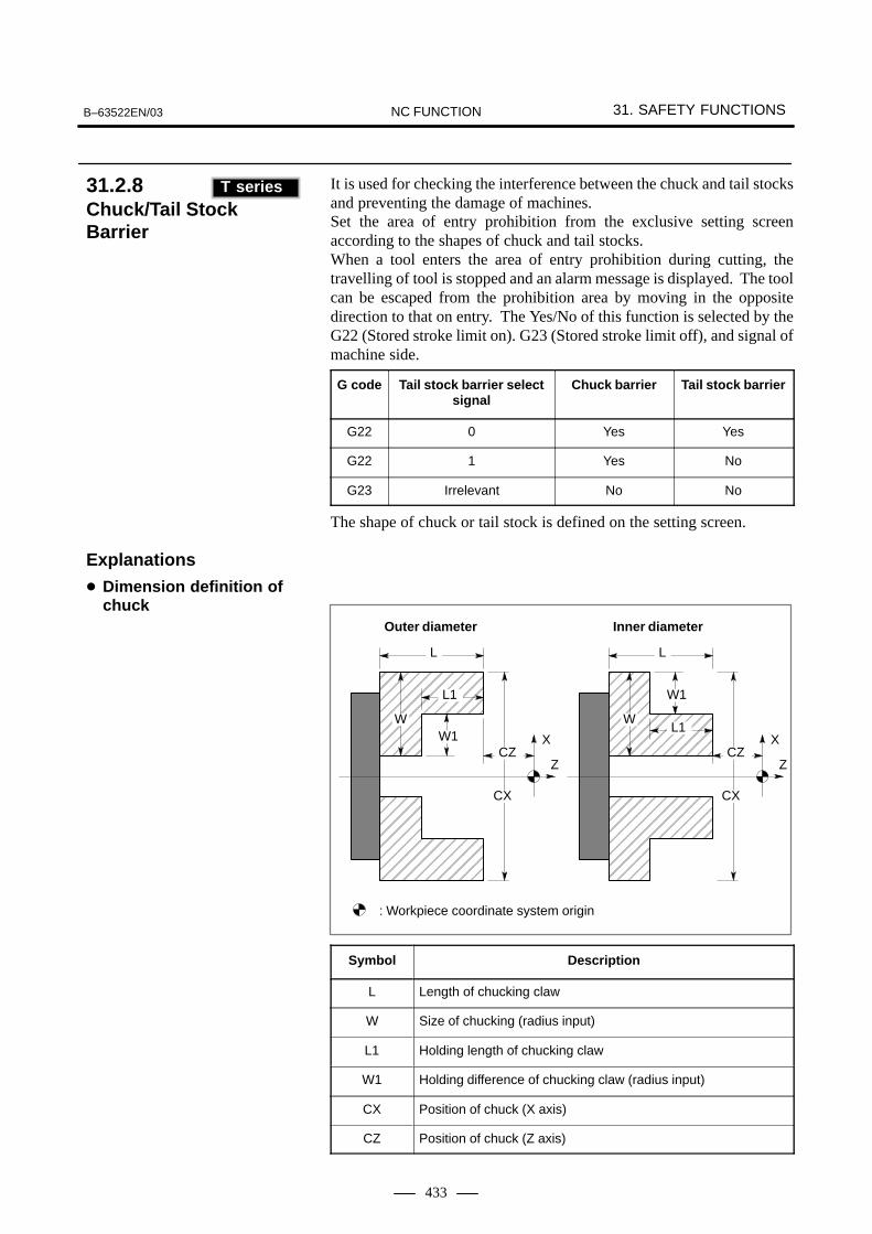
B–63522EN/03 31. SAFETY FUNCTIONSNC FUNCTION
433
It is used for checking the interference between the chuck and tail stocksand preventing the damage of machines.Set the area of entry prohibition from the exclusive setting screenaccording to the shapes of chuck and tail stocks.When a tool enters the area of entry prohibition during cutting, thetravelling of tool is stopped and an alarm message is displayed. The toolcan be escaped from the prohibition area by moving in the oppositedirection to that on entry. The Yes/No of this function is selected by theG22 (Stored stroke limit on). G23 (Stored stroke limit off), and signal ofmachine side.
G code Tail stock barrier selectsignal
Chuck barrier Tail stock barrier
G22 0 Yes Yes
G22 1 Yes No
G23 Irrelevant No No
The shape of chuck or tail stock is defined on the setting screen.
ÇÇÇÇÇÇÇÇÇÇÇÇÇÇÇÇÇÇÇÇÇÇÇÇÇÇÇÇÇÇ
ÇÇÇÇÇÇÇÇÇÇÇÇÇÇÇÇÇÇÇÇÇÇÇÇÇÇÇÇÇÇ
L1
W1
L
W
CX
CZX
Z
Outer diameter
ÇÇÇÇÇÇÇÇÇÇÇÇÇÇÇÇÇÇÇÇÇÇÇÇÇ
ÇÇÇÇÇÇÇÇÇÇÇÇÇÇÇÇÇÇÇÇÇÇÇÇÇ
L1
W1
L
W
CX
CZX
Z
Inner diameter
: Workpiece coordinate system origin
Symbol Description
L Length of chucking claw
W Size of chucking (radius input)
L1 Holding length of chucking claw
W1 Holding difference of chucking claw (radius input)
CX Position of chuck (X axis)
CZ Position of chuck (Z axis)
31.2.8Chuck/Tail StockBarrier (T series)
T series
Explanations
� Dimension definition ofchuck

31. SAFETY FUNCTIONS B–63522EN/03NC FUNCTION
434
TZL2
D3 D2 D1 D
L1
L
Z
X
: Workpiece coordinate system origin
Symbol Description
L Length of tail stock
D Diameter of tail stock (Diameter input)
L1 Length of tail stock (1)
D1 Diameter of tail stock (1) (Diameter input)
L2 Length of tail stock (2)
D2 Diameter of tail stock (2) (Diameter input)
D3 Hole diameter of tail stock (Diameter input)
TZ Position of tail stock (Z axis)
NOTEThis function cannot be used together with stored strokecheck 2 or 3.
� Dimension definition oftail stock

B–63522EN/03 31. SAFETY FUNCTIONSNC FUNCTION
435
This function checks for interference among the tool post and chucks andstops the machine safely. Three major interference check areas can be set,each of which is specified by using rectangles. Two of the threeinterference check areas can be moved and rotated.
ÅÅÅÅÅÅ
Interference check area A
Interference check
Interference check area C Interference check area B
Interference check
You can set the following interference check areas:
1) Interference check area A and interference check area BYou can set four rectangles. The entire area moves according to themovement along parameter–set two axes. In addition, the entire areacan be rotated according to the rotation on a parameter–set axis.
2) Interference check area CYou can set four rectangles. The area cannot be moved and rotated.
31.2.9Rotation AreaInterference Check

31. SAFETY FUNCTIONS B–63522EN/03NC FUNCTION
436
Axis feed specified to each axis can be stopped separately. If interlock isspecified to any of the moving axis during cutting feed, all axes of themachine movement will decelerate to a stop. When interlock signal isreset, the moving starts.
Feed of all axes can be inhibited. When all axes interlock is commandedduring move, it decelerates and stops. When all axes interlock signal isreset, the moving restarts.
Feeding of a specific axis in a specific direction can be inhibitedindependently of other axes. If the interlock signal is input to any of theaxes during a cutting feed operation, all axes decelerate and come to astop. When the interlock signal for each axis direction is released, the axesstart moving again.This function is usable for both the manual and automatic operations ofthe M series. For the T series, the DAU parameter (bit 4 of parameter No.3003) can be used to specify whether to make the function usable only forthe manual operation or for both the manual and automatic operations.
NOTETo enable axis direction–specific interlocking for theautomatic operation of the T series, set the DAU parameter(bit 4 of parameter No. 3003).
Feeding of all axes can be inhibited only during automatic operation.When the start lock signal is input while the axes are moving, all axesdecelerate and come to a stop. When the start lock signal is released, theaxes start moving again.
During automatic operation, the start of the next block can be disabled.A block that has already started is executed as is till its end.When the block start interlock is released, the execution of the next blockstarts.
During automatic operation, the start of a block containing a movecommand other than positioning can be disabled.When the cutting block start interlock is released, the execution of thenext block starts.When spindle rotation is specified or when the spindle speed is changed,the cutting block start interlock can be applied until the spindle reachesa target speed so that the next cutting block can be executed at the targetspindle speed.
31.3INTERLOCK
31.3.1Interlock per Axis
31.3.2All Axes Interlock
31.3.3Interlock for Each AxisDirection
31.3.4Start Lock
T series
31.3.5Block Start Interlock
31.3.6Cutting Block StartInterlock

B–63522EN/03 31. SAFETY FUNCTIONSNC FUNCTION
437
Feed rate can be decelerated by an external deceleration signal from themachine side. A feed rate after deceleration can be set by parameter.External deceleration is prepared every axis and every direction.When the tool is to be moved in the reverse direction, futile time may notbe wasted since no external deceleration is applied. By setting the corresponding parameter, whether to make this signaleffective only for rapid traverse mode or for all feed modes can bespecified for each axis and for each direction.This function allows the maximum of valid strokes and keeps shock to themachine to a minimum, to stops at stroke end.
When a cutting tool collides with the machine body or is damaged duringcutting, the load torque applied to the motors is larger than during normalfeeding or cutting. The abnormal load detection function calculates theload torque and transfers the value from the CNC to the PMC. If the loadtorque is larger than the value set in a parameter, the function stop themotor or reverses the motor rotation to retract the tool by the distance setin a parameter. In this way, damage to the machine is prevented. (Themotor rotation reverse function is available only for the servo motor axes.)Abnormal load detection can be disabled only for a specific axis.
The CNC stores disturbance load torque data detected by servo controlsoftware or spindle control software in internal memory.
1 Referencing stored torque data with the PMC via a window
2 Calculating the average, maximum and distribution of stored torquedata (statistical calculation) and reading these values through awindow
3 Plotting a graph of stored torque data on the torque monitor screen
4 Setting the detection level of the abnormal load detection alarm on thetorque monitor screen. (The abnormal load detection function is aseparate option.)
5 Saving stored torque data as sample data so that it can be comparedwith later data
6 Saving stored torque data in a memory card
CAUTIONThis function is a monitor function providing detaileddisturbance load torque data. This function allowsmonitoring of more detailed information about thedisturbance load for each axis. When this monitor functionis used to develop and supply a protection function for amachine or tool, a thorough confirmation must be madeusing the actual machine to ensure that an appropriateoperation can be obtained before the function is supplied.
31.4EXTERNALDECELERATION
31.5ABNORMAL LOAD DETECTION
31.6FINE TORQUE SENSING

31. SAFETY FUNCTIONS B–63522EN/03NC FUNCTION
438
The servo axis and spindle motor speeds are monitored. If the speed ofan axis exceeds a preset maximum (specified by parameter setting), thecorresponding signal is output to a Y address (specified by parametersetting) of the PMC.The following diagram illustrates the signal output state.
Max 2msec (servo motor)
Max 10msec (spindle motor)
Speed
? min–1 (Preset maximum)
CNC output signal<Y???#?>(Specified by parameter setting)
Max 16msec
Command for axis
Actual motor speed
Time
Note) The status of each signal is updated every 8 msec. (Fluctuations in the speed of less than 8 msec duration cannot be detected, therefore.)
(Specified by parameter setting)
31.7SERVO/SPINDLE MOTOR SPEED DETECTION

B–63522EN/03 32. STATUS OUTPUTNC FUNCTION
439
32 STATUS OUTPUT
32. STATUS OUTPUT B–63522EN/03NC FUNCTION
440
This signal is sent to the PMC when NC power is on and control becomespossible. Sending of this signal will be stopped when NC power is turnedoff.
This signal is sent to the PMC when the servo system becomes operatable.Axes necessary to be braked must be braked when this signal is not sent.
This signal shows that tape reader or main program in memory isrewinding.
This signal is transmitted when the NC comes under an alarm status.
This signal is sent out when pulse distribution of the M, S, T, or Bfunctions has ended, so that they can be used after move of thecommanded block ends.
This signal is sent out when it is under automatic operation.
This signal is sent out when automatic operation is being activated.
This signal is sent out when automatic operation is held by feed hold.
This signal is sent out to show that the NC has been reset.
This signal shows that an axis is under in–position status. This signal isoutput for all axes.
This signal shows that an axis is moving. This signal is sent out for everyaxis. This move signal can be combined with the interlock signal toautomatically clamp and unclamp the machine, or control on/off of thelubricating oil.
32.1NC READY SIGNAL
32.2SERVO READY SIGNAL
32.3REWINDING SIGNAL
32.4ALARM SIGNAL
32.5DISTRIBUTION END SIGNAL
32.6AUTOMATICOPERATION SIGNAL
32.7AUTOMATICOPERATION START SIGNAL
32.8FEED HOLD SIGNAL
32.9RESET SIGNAL
32.10IN–POSITION SIGNAL
32.11MOVE SIGNAL

B–63522EN/03 32. STATUS OUTPUTNC FUNCTION
441
This signal is output to show move direction of each axis. This signal isoutput for each axis.
This signal shows that the move command is done under rapid traverse.
This signal is output to show that the machine is under tapping mode (G63for M series) or tapping cycle (G74, G84 for M series), (G84, G88 for Tseries) is under operation.
This signal shows that the machine is under thread cutting mode (G33)or thread cutting cycle (T series).
This signal shows that the machine is under constant surface speed controlmode (G96).
This signal shows that input is done under inch input mode (G20).
To inform the exterior of the states of software operator’s panel, which areset via CRT/MDI, and machine operator’s panel, following DI stateoutput signals are sent.
� Mode-select check signal
� Single-block check signal
� Manual absolute on/off check signal
� Dry-run check signal
� Machine-lock check signal
� Auxiliary-function-lock check signal
� Optional block-skip check signal
� Mirror-image check signal
The position switch function outputs a signal to a specifiedcontrolled-axis when the machine coordinates of the controlled-axis arewithin the range specified by the corresponding parameter.The parameter specifies an arbitrary controlled-axis and the operatingrange (machine coordinates) within which the position switch signal isoutput.Up to sixteen position switch signals can be output.
32.12AXIS MOVE DIRECTION SIGNAL
32.13RAPID TRAVERSING SIGNAL
32.14TAPPING SIGNAL
32.15THREAD CUTTING SIGNAL
32.16CONSTANT SURFACESPEED CONTROL SIGNAL
32.17INCH INPUT SIGNAL
32.18DI STATUS OUTPUT SIGNAL
32.19POSITION SWITCH FUNCTION

32. STATUS OUTPUT B–63522EN/03NC FUNCTION
442
The high–speed position switch function obtains the current position ofan arbitrary controlled axis from the machine coordinates and thefeedback data from the position detector and outputs a signal if the currentposition is within a certain range. This function uses a shorter monitoringperiod than that of the ordinary position switch, enabling faster and moreaccurate monitoring.Up to 16 high–speed position switch signals can be output.
This function monitors the machine coordinates and operation directionfor an arbitrary controlled axis and turns the high–speed position switchsignal output on and off. There are two positions of which machinecoordinates are to be monitored. When the tool passes the coordinates ofone of the two positions in a specified direction, the signal goes on; whenthe tool passes the coordinates of the other position in a specifieddirection, the signal goes off. These coordinates and directions are setwith parameters.
32.20HIGH–SPEEDPOSITION SWITCH
32.21DIRECTIONDECISION TYPE HIGH–SPEEDPOSITION SWITCH

B–63522EN/03 33. EXTERNAL DATA INPUTNC FUNCTION
443
33 EXTERNAL DATA INPUT
The external data input is as follows.
� External tool compensation
� External program number search
� External work coordinate system shift
� External machine zero point shift
� External alarm message
� External operator message
� Substitution of the number of machined parts and number of requiredparts
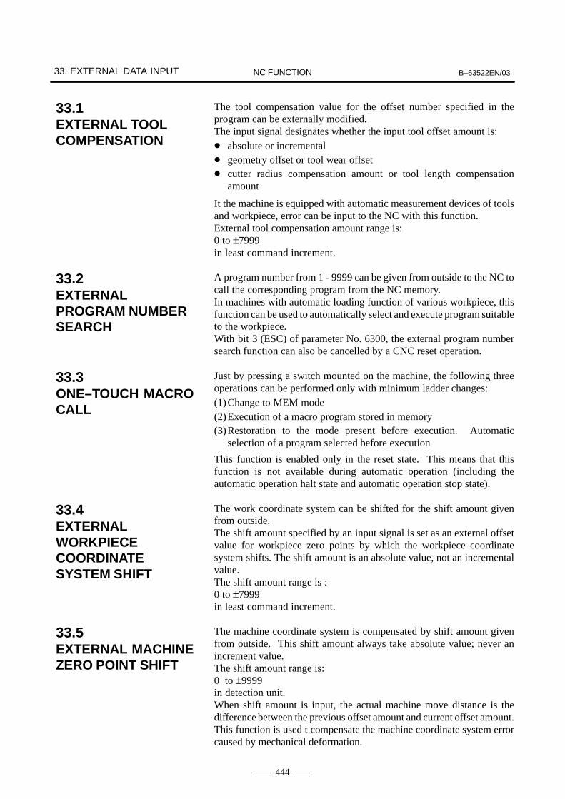
33. EXTERNAL DATA INPUT B–63522EN/03NC FUNCTION
444
The tool compensation value for the offset number specified in theprogram can be externally modified.The input signal designates whether the input tool offset amount is:� absolute or incremental� geometry offset or tool wear offset� cutter radius compensation amount or tool length compensation
amount
It the machine is equipped with automatic measurement devices of toolsand workpiece, error can be input to the NC with this function. External tool compensation amount range is: 0 to ±7999in least command increment.
A program number from 1 - 9999 can be given from outside to the NC tocall the corresponding program from the NC memory.In machines with automatic loading function of various workpiece, thisfunction can be used to automatically select and execute program suitableto the workpiece.With bit 3 (ESC) of parameter No. 6300, the external program numbersearch function can also be cancelled by a CNC reset operation.
Just by pressing a switch mounted on the machine, the following threeoperations can be performed only with minimum ladder changes:(1)Change to MEM mode(2)Execution of a macro program stored in memory(3)Restoration to the mode present before execution. Automatic
selection of a program selected before execution
This function is enabled only in the reset state. This means that thisfunction is not available during automatic operation (including theautomatic operation halt state and automatic operation stop state).
The work coordinate system can be shifted for the shift amount givenfrom outside. The shift amount specified by an input signal is set as an external offsetvalue for workpiece zero points by which the workpiece coordinatesystem shifts. The shift amount is an absolute value, not an incrementalvalue.The shift amount range is :0 to ±7999in least command increment.
The machine coordinate system is compensated by shift amount givenfrom outside. This shift amount always take absolute value; never anincrement value.The shift amount range is: 0 to ±9999in detection unit.When shift amount is input, the actual machine move distance is thedifference between the previous offset amount and current offset amount.This function is used t compensate the machine coordinate system errorcaused by mechanical deformation.
33.1EXTERNAL TOOL COMPENSATION
33.2EXTERNAL PROGRAM NUMBER SEARCH
33.3ONE–TOUCH MACROCALL
33.4EXTERNALWORKPIECECOORDINATESYSTEM SHIFT
33.5EXTERNAL MACHINEZERO POINT SHIFT

B–63522EN/03 33. EXTERNAL DATA INPUTNC FUNCTION
445
By sending alarm number from outside, the NC is brought to an alarmstatus; an alarm message is sent to the NC, and the message is displayedon the screen of the NC. Reset of alarm status is also done with externaldata.Up to 4 alarm numbers and messages can be sent at a single time. Alarms0 to 999 can be sent. To distinguish these alarms from other alarms, theCNC displays them by adding 1000 to each alarm number. The messagesof up to 32 characters can be sent together with an alarm.
Message to the operator is given from outside the NC, and the messageis displayed. The message is sent after a message number 0 to 999. Either a messageconsisting of up to 255 characters or up to four messages each consistingof up to 63 characters can be displayed at the same time by parametersetting.The message numbers 0 to 99 are displayed along with the message.To distinguish these alarms from other alarms, the CNC displays them byadding 2000 to each alarm number. When a message from 100 to 999 isdisplayed, the message number is not displayed; only its text is displayed.An external data will clear the operator messages.
The number of required parts and the number of machined parts can bepreset externally. Values from 0 to 9999 can be preset.
33.6EXTERNAL ALARM MESSAGE
33.7EXTERNALOPERATOR’SMESSAGE
33.8SUBSTITUTION OF THE NUMBER OF REQUIRED PARTS AND NUMBER OF MACHINED PARTS

34. KEY INPUT FROM PMC (EXTERNAL KEY INPUT) B–63522EN/03NC FUNCTION
446
34 KEY INPUT FROM PMC (EXTERNAL KEY INPUT)
When the PMC inputs the code signal corresponding to a key on the MDIpanel to the CNC, the code signal can be input in the same way as withactual operation of the key on the MDI panel. For example, this functionis usable in the following case:After allowing to travel the tool at an arbitrary machining position byusing the playback function (option), when to store its positions as theprogram command, X, Y, Z, <INSERT>, etc. must be input via keyoperations. However, these operations can be realized simply bydepressing a switch on the operator’s panel at the machine side.When the switch is pressed, the PMC inputs code signals correspondingto keys X, Y, Z, and <INSERT> to the CNC. This produces the sameresults as with actual key operations.


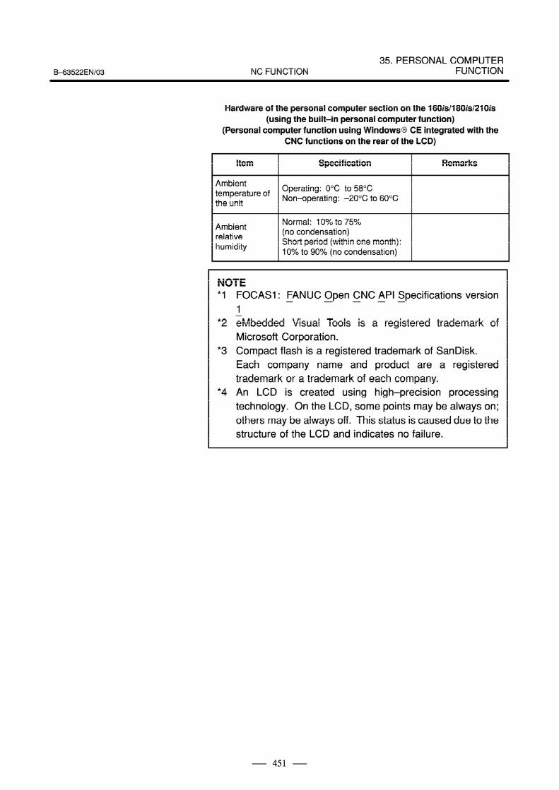


36. INTERFACE WITH THE POWER MATE CNCB–63522EN/03 NC FUNCTION
455
36 INTERFACE WITH THE POWER MATE CNC

36. INTERFACE WITH THE POWER MATE CNC B–63522EN/03NC FUNCTION
456
This function allows the use of a manual pulse generator on the host sideto perform manual handle feed for the (β servo unit. The host posts pulsesfrom the manual pulse generator to the (β servo unit via the I/O Link. Amagnification can also be applied to the pulse output signal of the manualpulse generator by parameter setting. This function can be used only withthe peripheral equipment control interface.
36.1FANUC SERVOMOTOR β SERIES I/OLINK OPTIONMANUAL HANDLEINTERFACE(PERIPHERALEQUIPMENTCONTROL)

III. AUTOMATIC PROGRAMMINGFUNCTION


1. OUTLINE OF CONVERSATIONAL AUTOMATIC
PROGRAMMINGB–63522EN/03 AUTOMATIC PROGRAMMING FUNCTION
459
1 OUTLINE OF CONVERSATIONAL AUTOMATICPROGRAMMING
FANUC provides conversational automatic programming functions forlathes and machining centers.With these conversational automatic programming functions, the user canenter data and create machining programs easily by following thedisplayed illustrations and instructions. In addition, program checking and modifications can be performed easily.

2. CONVERSATIONAL AUTOMATIC PROGRAMMING FUNCTION FOR LATHES B–63522EN/03AUTOMATIC PROGRAMMING FUNCTION
460
2 CONVERSATIONAL AUTOMATIC PROGRAMMINGFUNCTION FOR LATHES
There are three conversational automatic programming functions forlathes: Symbol CAPi T and Super CAPi T, and Manual Guide for lathe.The difference between the two functions is in the program input method.Symbol CAPi T uses the symbolic FAPT method for inputting programs.In Super CAPi T and Manual Guide for lathe programs are entered byselecting machining types.For the 160i/180i/210i, use the CNC screen display function.For the 160is/180is/210is, this function is unavailable.

2. CONVERSATIONAL AUTOMATIC PROGRAMMING FUNCTION
FOR LATHESB–63522EN/03 AUTOMATIC PROGRAMMING FUNCTION
461
Symbol CAPi T is a conversational automatic programming function forlathes. It has the following features:
� Part figures can be input in a batch by using the symbolic keys.
� Even complicated part figures can be input by using the automaticintersection calculation function.
� The automatic process determination function creates necessaryprocesses automatically.
� Any cutting direction or area can be specified.
� NC data can be created without superfluous movement, such as cuttingthrough air.
� By using MTF, NC data suitable for the particular machine being usedcan be created.
� Coloring of screens can be set, and soft keys can be displayed to havea “raised” look.
Symbol CAPi T can be used with the following lathes:
� 1–spindle/1–turret lathe
� 1–spindle/2–turret lathe
� 2–spindle (main spindle and sub spindle)/1–turret lathe
� 2–spindle (main spindle and sub spindle)/2–turret lathes
� Lathe with Y–axis/C–axis machining functions
� Lathe with the function for tilt plane machining by a tool tilt axis
� Lathe with chasing tool
� Vertical lathe
2.1Symbol CAPi T
2.1.1Features
2.1.2Applicable Machines

2. CONVERSATIONAL AUTOMATIC PROGRAMMING FUNCTION FOR LATHES B–63522EN/03AUTOMATIC PROGRAMMING FUNCTION
462
In Super CAPi T, the following machining types can be determinedautomatically or selected manually:
� Outer surface machining
� Inner surface machining
� Grooving/residual machining
� Threading
� Cutting off
� Bar feed
� Center drilling/drilling/reaming/tapping
� C–axis center drilling/drilling/tapping
� C–axis front face nothing
� C–axis cylindrical grooving
� Y–axis center drilling/drilling/tapping(*1)
� Y–axis pattern machining(*1)
� Y–axis contouring(*1)
� Tilt plane center drilling, drilling, and tapping(*1)
� Tilt plane pattern machining(*1)
� Tilt plane contouring(*1)
� Auxiliary machining(*1)(*2)
NOTE*1 Y–axis machining, tilt plane, and miscellaneous machining
are not determined automatically.*2 A subprogram can be called from the conversational
program.
2.1.3Outline of theConversationalAutomaticProgramming Function
Machining types

2. CONVERSATIONAL AUTOMATIC PROGRAMMING FUNCTION
FOR LATHESB–63522EN/03 AUTOMATIC PROGRAMMING FUNCTION
463
Operations with Super CAPi T always begin with the basic menu screenshown at the following. If the user cannot determine the next operationon a conversational screen, the user can press the leftmost soft key[ESCAPE] to return to the display of this basic menu screen.
=== FAPT EXECUTION PROCESS ===
SERECTION OF MATERIAL & SETTING OF BLANK SIZE
INPUT OF PART FUGURE (INPUT OF BLANK FIGTURE)
SETTING OF HOME POSITION/INDEX POSITION
MACHINING DEFINITION
NC DATA PREPARATION
MACHINING SIM-ULATION
METRIC
END 1 2 3 4 5 6 EXEC
*NC SIDE*
O 0000N 00000
X–AXIS 0.000
Z–AXIS 0.000
S 000000T 000000M 000000
When a size is entered, a guide figure can be drawn by pressing the[HELP] soft key.
*** BLANK AND PART *** 01–01
NO. MATERIAL 1 S45C
MATERIAL NO. MN = 1 2 SOM. . . . . . . . . . . . . . . . . STANDARD SURFACE ROUGHNESS NR = 2 3 FCDRAWING FORMAT DF = 2 4 AL. . . . . . . . . . . . . . . BLANK FUGURE BF = 1 5 SUS. . . . . . . . . . . . . . . . . BLANK SIZE 6 MATERIAL6
DIAMETER D = 100. 7 MATERIAL7. . . . . . . . . . . 8 MATERIAL8
LENGTH L = 85. 9 MATERIAL9. . . . . . . . . . . . . BASE LINE ZP = 3. 10 MATERIAL10. . . . . . . . . . . . . . . . . . . . .
11 MATERIAL1112 MATERIAL1213 MATERIAL13
DEPTH OF CHUCKING ZC = 0. 14 MATERIAL14. . . . . . . . . . . 15 MATERIAL1516 MATERIAL1617 MATERIAL17
MM = METRIC
*NC SIDE*
O 0000N 00000
X–AXIS 0.000
Z–AXIS 0.000
S 000000T 000000M 000000
ESCAPE MAT. CURSOR CURSOR NEXTNAME ↑ ↓ PAGE
Basic menu screen
Material selection andblank size setting screen

2. CONVERSATIONAL AUTOMATIC PROGRAMMING FUNCTION FOR LATHES B–63522EN/03AUTOMATIC PROGRAMMING FUNCTION
464
Part figures are input in a batch by using symbolic keys ( , , , ,
, , , , , and ).
Functions are available for simplifying part figure input; these functionsinclude the automatic intersection calculation, pocket calculator formatnumeric calculation, continuous groove input, chamfering batch input,and figure copy functions.The input figures are displayed directly on the screen so that they can bechecked easily.
*** BLANK AND PART *** PART FIGURE S = 1.47 01–06FIGURE ELEMENT ↑C→G→R→G→TC↓CG↓TC←G↓C←. . . . . . . . .
*** SELECT SOFT KEY ***METRIC
*NC SIDE*
O 0000N 00000
X–AXIS 0.000
Z–AXIS 0.000
S 000000T 000000M 000000
ESCAPEBACK CORR. CORRE– NEWPAGE ERASE CTION
LIST DRAWNG NEXTMODE RANGE PAGE
The automatic process determination function automatically creates theprocesses shown on the following.The automatic process determination function automatically determinesmachining types, tool data, cutting areas, and cutting conditions.On this screen, processes and edit operations (deletion and insertion ofprocesses) can be selected manually.
*** MACHINING DEFINITION *** KINDS OF MACHINING 04–02
PROC.01CENTER DRILLING T0101 X 150. Z 150.PROC.02DRILLING T0202 X 150. Z 150.PROC.03DRILLING T0303 X 150. Z 150.PROC.04ROUGHING OF OUTER FIGURE T0909 X 150. Z 150.PROC.05ROUGHING OF INNER FIGURE T1111 X 150. Z 150.PROC.06FINISHING OF OUTER FIGURE T1010 X 150. Z 150.PROC.07FINISHING OF INNER FIGURE T1212 X 150. Z 150.PROC.08ROUGHING OF GROOVE T0505 X 150. Z 150.PROC.08FINISHING OF GROOVE T0404 X 150. Z 150.PROC.10GROOVING OR NECKING T0606 X 150. Z 150.PROC.11THREADING T1717 X 150. Z 150.PROC.12THREADING T0808 X 150. Z 150.PROC.13CUT OFF T0707 X 150. Z 150.PROC.14BAR FEED T1515 X 150. Z 150.PROC.15
*** SELECT SOFT KEY ***
METRIC
*NC SIDE*
O 0000N 00000
X–AXIS 0.000
Z–AXIS 0.000
S 000000T 000000M 000000
ESCAPEPROC. CENTERTURN GROOV.DELETE HOLE THREAD
CURSOR CURSOR NEXT↑ ↓ PAGE
Part figure input screen
Process directorydisplay

2. CONVERSATIONAL AUTOMATIC PROGRAMMING FUNCTION
FOR LATHESB–63522EN/03 AUTOMATIC PROGRAMMING FUNCTION
465
Tool data input and modifications are made on this screen. A toolcurrently selected is indicated on the screen, allowing the user to easilycheck tool data.
*** MACHINING DEFINITION *** TOOL DATA 04–03PROC.04 ROUGHING OF OUTER FIGURE T0909 X 150. Z 150.
MACHINING START POSITION:TOOL SELECT NO. TN = 09 DX0 = 150. Z0 = 150.. . . TOOL OFFSET NO. TM = 09. . . TOOL ID NO. ID = 500. . . . . . .
TOOL TYPE TP ; GENERAL. . . .
NOSE RADIUS RN = 0.8. . . . . . . CUTTING EDGE AC = 8.. . . . . . NOSE ANGLE AN = 75.. . . . . . . . . PROTECTION ANGLE AP = 3.. . VIRTUAL TOOL POS. XN = 0.8
ZN = 0.8. SETTING ANGLE AS = –90.. . . . . SETTING POSITION XS = 0.. .
ZS = 0..
HOLDER NO. ML = 13. . . . . . . . .
TN = METRIC
*NC SIDE*
O 0000N 00000
X–AXIS 0.000
Z–AXIS 0.000
S 000000T 000000M 000000
ESCAPEBACK TAB NEXT TOOLPAGE TOOL DATA
TOLINGCURSOR CURSORCHECK NEXTINFOR. ↑ ↓ PAGE
Cutting directions and cutting areas are specified using the arrow keys.Any cutting direction and area can be specified.
ESCAPEBACK ↑ ↓ →PAGE
← CURSOR CURSORDRAWNG NEXT↑ ↓ RANGE PAGE
*** MACHINING DEFINITION *** CUTTING AREA DEFINITION 04–05PROC.04 ROUGHING OF OUTER FIGURE T0909 X 150. Z 150.
CUTTING DIRECTION CD = ↓. . . . . . . .
CUTTING AREA DEFINITION: START POINT END POINT ( 68. / 0. ) ( 27. / 0. ) DIVIDING DIRECTION DS = ↑ DIVIDING DIRECTION DE = ↓. . . . .
CD = METRIC
*NC SIDE*
O 0000N 00000
X–AXIS 0.000
Z–AXIS 0.000
S 000000T 000000M 000000
Tool data input screen
Screen for settingcutting directions andcutting areas
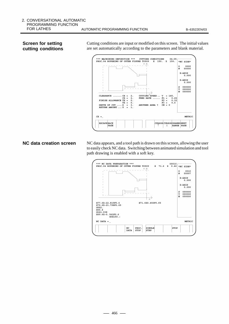
2. CONVERSATIONAL AUTOMATIC PROGRAMMING FUNCTION FOR LATHES B–63522EN/03AUTOMATIC PROGRAMMING FUNCTION
466
Cutting conditions are input or modified on this screen. The initial valuesare set automatically according to the parameters and blank material.
ESCAPEBACKPAGE
CURSOR CURSORDRAWNG NEXT↑ ↓ RANGE PAGE
*** MACHINING DEFINITION *** CUTTING CONDITIONS 04–05PROC.04 ROUGHING OF OUTER FIGURE T0909 X 150. Z 150.
CLEARANCE CX = 2. CUTTING SPEED V = 145.. . . . . . . . . CZ = 2. FEED RATE F1 = 0.65. . . . . .
FINISH ALLOWANCE TX = 0. F2 = 0.32TZ = 0. F3 = 0.6
DEPTH OF CUT D = 3. ANOTHER AREA ? CN = 0. . . . RETURN AMOUNT U = 1.. . .
CX =_ METRIC
*NC SIDE*
O 0000N 00000
X–AXIS 0.000
Z–AXIS 0.000
S 000000T 000000M 000000
NC data appears, and a tool path is drawn on this screen, allowing the userto easily check NC data. Switching between animated simulation and toolpath drawing is enabled with a soft key.
NC PROC.DATA STOP
SINGLE STOPSTEP
*** NC DATA PREPARATION *** O0010PROC.04 ROUGHING OF OUTER FIGURE T0909 X 71.6 Z 0.46
X77.6Z–22.815F0.6 X71.6Z0.456F0.65X79.6Z–21.798F0.65G0Z2.X66.4G1Z1.038X69.6Z–0. 562F0.6
G0X150.:
NC DATA = _ METRIC
*NC SIDE*
O 0010N 00007
X–AXIS 0.000
Z–AXIS 0.000
S 000000T 000000M 000000
Screen for settingcutting conditions
NC data creation screen

2. CONVERSATIONAL AUTOMATIC PROGRAMMING FUNCTION
FOR LATHESB–63522EN/03 AUTOMATIC PROGRAMMING FUNCTION
467
The cutting time and rapid traverse time are displayed for each machiningtype. A bar chart is displayed so that the user can check the time allotmentat a glance.
ESCAPE
*** NC DATA PREPARATION *** PROCESS LIST 04–34
<–––> 0MIN 52SECNO. CUTTING RAPID01 CENTER DRILLING 0.02 0.0702 DRILLING 0.44 0.0803 DRILLING 0.34 0.0904 ROUGHING OF OUTER FIGURE 0.39 0.0905 ROUGHING OF INNTER FIGURE 0.06 0.0806 FINISHING OF OUTER FIGURE 0.18 0.0707 FINISHING OF INNTER FIGURE 0.06 0.0708 ROUGHING OF GROOVE 1.05 0.0808 FINISHING OF GROOVE 0.41 0.0710 GROOVING OR NECKING 0.16 0.0811 THREADING 0.30 0.1212 THREADING 0.06 0.1213 CUT OFF 1.10 0.0814 BAR FEED 0.11 0.09
*** PRESS SOFT KEY ***
METRIC
*NC SIDE*
O 0000N 00000
X–AXIS 0.000
Z–AXIS 0.000
S 000000T 000000M 000000
PAGEEJECT
The user can check the memory operation conditions on the screen. Afunction for checking for interference between the chuck/tailstock andtool is provided. An interference check can be made before actualoperation by performing memory operation with the machine lock set toON.
END
*** CHECKING OF NC DATA *** SCALE VALUE 0.922 10–01
START METRIC
*NC SIDE*
O 0010N 00007
X–AXIS 70.000
Z–AXIS -20.260
S 000000T 001010M 000003
CHECK ORIGI– TOOL PARAM–START NAL PATH ETER
Machining time displayscreen
Animated simulationscreen

2. CONVERSATIONAL AUTOMATIC PROGRAMMING FUNCTION FOR LATHES B–63522EN/03AUTOMATIC PROGRAMMING FUNCTION
468
Super CAPi T is conversational automatic programming functions a forlathes. It has the following features:
� Simple operation
� Program input by selecting machining processes
� Conversational setup operation by following displayed setupinstructions
� Direct execution of conversational programs. The program can alsobe converted to an NC format, then executed.
� Customization by the machine tool builder.
Super CAPi T is a development of Super CAP T for Series 16i/18i–TA.It features the following new functions:
1 Background color for the display screen, and 3–D frames for windowsand soft keys
2 Buttons appear “pressed” when selected
3 Machining simulation for turning based on a solid model(Super CAP T for Series 16i/18i–TA can be used this function)
4 Tool trajectory drawing based on isometric projection in C–/Y–axismachining simulation(Super CAP T for Series 16i/18i–TA can be used this function)
5 Selectable screen display colors, with the saving of up to four colorschemes supported
All other functions, such as screen displays, key operations, andmachining functions, are the same as those of super CAP T.Moreover, machining programs, tool data, and conversational functionparameters created with Super CAP T can also be used with Super CAPiT.
Super CAPi T can be used with the following lathes:
� 1–spindle/1–turret lathe
� 1–spindle/2–turret lathe
� Facing 2–spindle/2–turret lathe (The two turrets operateindependently of each other.)
� 2–spindle (main spindle and sub spindle)/1–turret lathe
� Lathe with Y–axis/C–axis machining functions
� Composite lathe (facing 2–spindles/2–turret type lathes)
� Composite lathe (facing 2–spindles/3–turret type lathes)
2.2Super CAPi T
2.2.1Features
About Super CAPi T
2.2.2Applicable Machines

2. CONVERSATIONAL AUTOMATIC PROGRAMMING FUNCTION
FOR LATHESB–63522EN/03 AUTOMATIC PROGRAMMING FUNCTION
469
In Super CAPi T, the following machining types can be selected:
� Bar machining (External diameter/External diameter+automaticresidual/Internal diameter/Internal diameter+automatic residual/Endface/End face+automatic residual)
� Pattern repeating (External diameter/Intermediate of externaldiameter /Internal diameter/Intermediate of internal diameter)
� Residual machining (External diameter/Internal diameter/Endface/End of internal bottom)
� End facing
� Threading (External diameter/Internal diameter)
� Grooving (External diameter/Internal diameter/End face)
� Necking
� Center drilling/drilling/reaming/boring/tapping� Single action
NOTEA command equivalent to one block of an NC program canbe input conversationally.
� Subcall
NOTEA subprogram can be called from the conversationalprogram.
� Auxiliary processes and transfer process
NOTEThe machine tool builder can include machine–specificoperations in the conversational function.
� M code/end process� C–axis center drilling/drilling/reaming/boring/tapping (End face/Side
face/Incline face *1)
� C–axis grooving (End face/Side face)
� C–axis nothing (End face/Side face)
� C–axis cylindrical machining
� Y–axis center drilling/drilling/reaming/tapping (End face/Sideface/Incline face *1)
2.2.3Outline of theConversationalAutomaticProgramming Function
Machining types

2. CONVERSATIONAL AUTOMATIC PROGRAMMING FUNCTION FOR LATHES B–63522EN/03AUTOMATIC PROGRAMMING FUNCTION
470
� Y–axis milling (End face/Side face/Incline face *1)� C–axis milling machining (End face/Side face)� Balance cut (External diameter/Inside of external diameter (Residual
of external diameter)/Reverse of external diameter/Reverse of residualof external diameter)
NOTE1 These operations are enabled by the B–axis conversational
programming function that is an optional function.
Operations with Super CAPi T always begin with the basic menu screenshown here. If the user cannot determine the next operation on aconversational screen, the user can press the leftmost soft key toreturn the display to this basic menu screen.
EDITMODE
MEMMODE
MEMMODE
MEMMODE
FANUC Super CAP T Ver. Z3.0
PREP A NEW PROCESS PROGRAM
12:05:57 MDI
END 1 2 3 4 5 6
EDIT THE PROCESSING PROGRAM
PROCESSING SIMULATION
DIRECT OPERATION OF CAP PROGRAM
CONVERT TO NC PROGRAM
TOOL,CUTTING CONDITION DATA
TOOL OFFSET DATA
EDIT NC PROGRAM
POSITION
CAP. : HEAD–L
7 8 9 +
A program can be input easily by following the instructions displayed ina window.
DELETEINSERT PROGRMWINDOW PROCESEND OFF EDIT
<
EDIT THE PROCESSING PROGRAM [CAP. : HEAD–L]NO. =0194 NAME=BOZAI TEST–1INTAL SET MATERIAL SHAPE OUT–DIA IN–DIA WORK–LNG MAX–S COOLANT
FC25 BAR 202.000 105.000 2500 ON FINISHX FINISHZ E–REMOVL PROD–LNG
0.500 0.300 2.000 10.000PROC(01) AREA HEAD TOOL–NO OUT–SPD FEED/REV CUT–DEPH T–CODEBAR (R) OUTER END HEAD–L 101 80PROC(01) AREA HEAD ROUGHNES TOOL–NOBAR (F) OUTER END HEAD–L 5 101
START X= 0.000 Z= 0.000 ↑ X= 48.000 Z= 0.000
CHAMFR X= 50.000 Z= 1.000 ← X= 50.000 Z= 15.858
ROUND X= 55.858 Z= 22.929X= 67.071 Z= 28.536
ROUND X= 70.000 Z= 32.072 ← X= 70.000 Z= 35.567
ROUND X= 80.001 Z= 44.227X= 96.536 Z= 49.000
OUTSIDE DIA.
MACHIN TOOL DETAIL PLOTCOND. DATA DATA
Basic menu screen
Conversational programinput screen

2. CONVERSATIONAL AUTOMATIC PROGRAMMING FUNCTION
FOR LATHESB–63522EN/03 AUTOMATIC PROGRAMMING FUNCTION
471
A machining profile can be input easily by using intersection automaticcalculation and pocket calculator format calculation.The input profile is displayed directly on the screen so that the user cancheck the profile easily.
EDIT THE PROCESSING PROGRAM [CAP. : HEAD–L]NO. =0194 NAME=BOZAI TEST–1INTAL SET MATERIAL SHAPE OUT–DIA IN–DIA WORK–LNG MAX–S COOLANT
FC25 BAR 202.000 105.000 2500 ON FINISHX FINISHZ E–REMOVL PROD–LNG
0.500 0.300 2.000 10.000PROC(01) AREA HEAD TOOL–NO OUT–SPD FEED/REV CUT–DEPH T–CODEBAR (R) OUTER END HEAD–L 101 80 0.50 5.000 0101PROC(01) AREA HEAD ROUGHNES TOOL–NO CUT–SPD FEED/REV T–CODEBAR (F) OUTER END HEAD–L 5 101 120 0.20 0101
START X= 0.000 Z= 0.000 ↑ X= 48.000 Z= 0.
CHAMFR X= 50.000 Z= 1. ← X= 50.000 Z= 15.
ROUND X= 55.858 Z= 22.X= 67.071 Z= 28.
ROUND X= 70.000 Z= 32. ← X= 70.000 Z= 35.
ROUND X= 80.001 Z= 44.X= 96.536 Z= 49.
+WINDOWINSERT ALTER ALTER DELETEOFF FIGURE
<
CONTR FORM (TAPER LINE)DIRECTION B=TAPER END X CORD. X= 70.000TAPER END Z CORD. Z= 30.000COMPONENT X I=COMPONENT Z/ANGLEK/J= 45.000LENGTH Q=ROUGHNESS(1 ~10 )SR= 5
MACHIN TOOL DETAIL PLOTCOND. DATA DATA
The entire machining program can be checked easily from the processdirectory display screen that also indicates the execution time for eachprocess.In addition, editing operations including movement, copy, anddeletion of processes can be performed on this screen.
RE–NUMTRANS. DELETE COPY< EDIT RETURN PLOT GUIDE
EDIT THE PROCESSING PROGRAM *** PROCESS EDIT *** [CAP. : HEAD–L]HEAD–L HEAD–R
INTAL SET FC25 BAR INTAL SET FC25 BAR
PROC(01) BAR OUTER END PROC(04) TRANSROUGH T0101
0M0S 0M 0SPROC(02) BAR OUTER END PROC(05) BAR OUTER END
FIN T0101 ROUGH T0101 1M11S ������������������������ 1M31S ����������������������������
PROC(02) DRILLING (DRILLING) PROC(05) BAR OUTER ENDT0808 FIN T0101
0M24S ��������� 0M47S �����������������
PROC(03) BAR INNER END PROC(06) BAR INNER ENDROUGH T0303 ROUGH T0303
0M 4S 0M10S yxyxyxyx
HEAD–L 1M42S 0101����������������02�������03030408HEAD–R 2M35S 0405�����������������������05���������������06��060708
Conversational programinput screen (inputting amachining profile)
Process directorydisplay screen
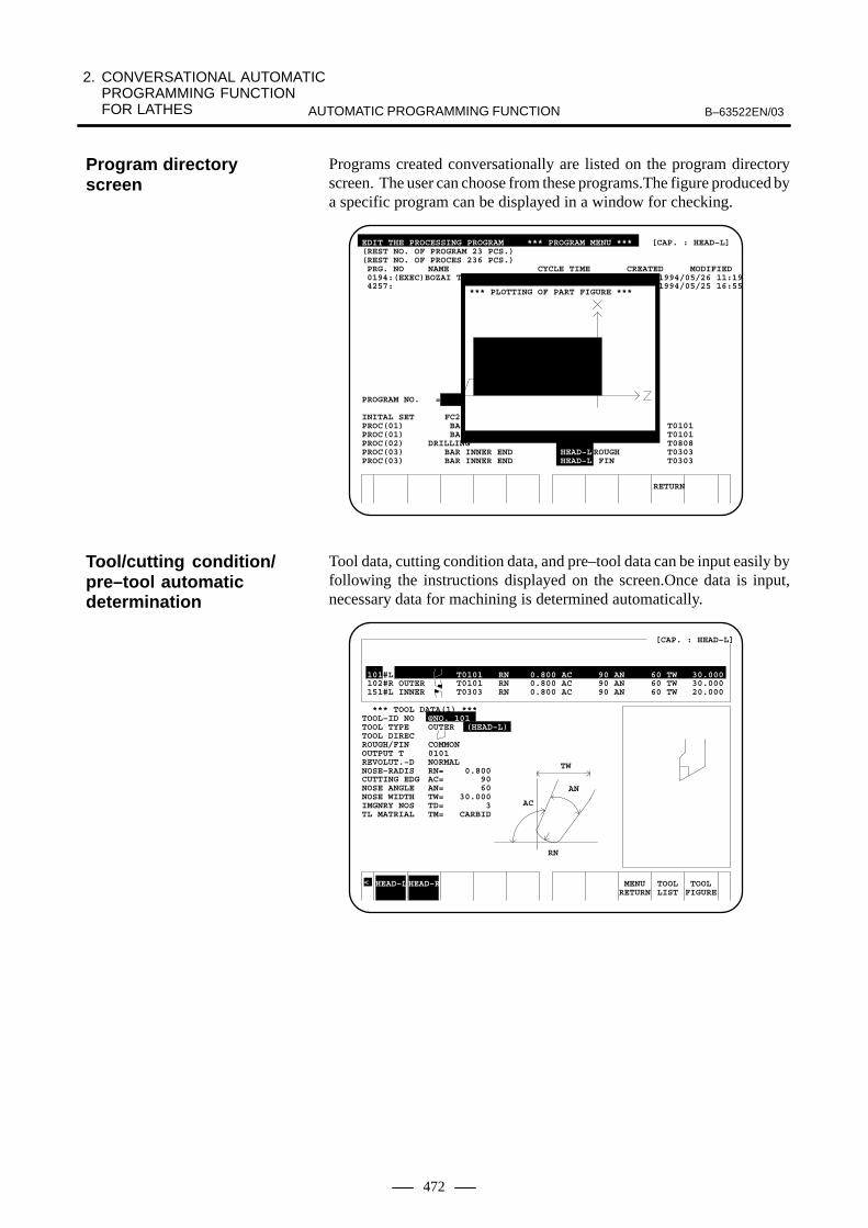
2. CONVERSATIONAL AUTOMATIC PROGRAMMING FUNCTION FOR LATHES B–63522EN/03AUTOMATIC PROGRAMMING FUNCTION
472
Programs created conversationally are listed on the program directoryscreen. The user can choose from these programs.The figure produced bya specific program can be displayed in a window for checking.
EDIT THE PROCESSING PROGRAM *** PROGRAM MENU *** [CAP. : HEAD–L](REST NO. OF PROGRAM 23 PCS.)(REST NO. OF PROCES 236 PCS.) PRG. NO NAME CYCLE TIME CREATED MODIFIED 0194:(EXEC)BOZAI T 1994/05/26 11:19 4257: 1994/05/25 16:55
PROGRAM NO. =
INITAL SET FC2PROC(01) BA T0101PROC(01) BA T0101PROC(02) DRILLING T0808PROC(03) BAR INNER END HEAD–LROUGH T0303PROC(03) BAR INNER END HEAD–L FIN T0303
*** PLOTTING OF PART FIGURE ***
RETURN
Tool data, cutting condition data, and pre–tool data can be input easily byfollowing the instructions displayed on the screen.Once data is input,necessary data for machining is determined automatically.
HEAD–LHEAD–R
[CAP. : HEAD–L]
101#L OUTER T0101 RN 0.800 AC 90 AN 60 TW 30.000 102#R OUTER T0101 RN 0.800 AC 90 AN 60 TW 30.000 151#L INNER T0303 RN 0.800 AC 90 AN 60 TW 20.000
*** TOOL DATA(1) ***TOOL–ID NO @NO. 101TOOL TYPE OUTER (HEAD–L)TOOL DIRECROUGH/FIN COMMONOUTPUT T 0101REVOLUT.–D NORMALNOSE–RADIS RN= 0.800CUTTING EDG AC= 90NOSE ANGLE AN= 60NOSE WIDTH TW= 30.000IMGNRY NOS TD= 3TL MATRIAL TM= CARBID
<
AC
RN
AN
TW
MENU TOOL TOOLRETURN LIST FIGURE
Program directoryscreen
Tool/cutting condition/pre–tool automaticdetermination

2. CONVERSATIONAL AUTOMATIC PROGRAMMING FUNCTION
FOR LATHESB–63522EN/03 AUTOMATIC PROGRAMMING FUNCTION
473
Tool assignment to the turret and tool offset measurement for each toolcan be performed easily on the tooling screen which lists the tools usedin the machining program.
HEAD–LHEAD–R Y–AXIS WEAROFFSET OFFSET
*** HEAD–L TOOLING DATA *** [CAP. : HEAD–L] PAGE 01/01
PROC PROCNAME USING TOOL GEOMETRY OFS X GEOMETRY OFS Z RN/WN/DD/TR/TW T–CODE01 BAR (R) –200.000 –200.000 RN 0.800 010101 BAR (F) –200.000 –200.000 RN 0.800 010102 DRILLING DRILL –200.000 –200.000 DD 30.000 080303 BAR (R) –200.000 –200.000 RN 0.800 030303 BAR (F) –200.000 –200.000 RN 0.800 0303
GEOXETRY OFS X
< PREPAR TOOL RETURNDISPLY
By following the setup instructions displayed conversationally, toolgeometry compensation, tool–change position, chuck barrier, andtailstock barrier can be set easily.
[CAP. : HEAD–L]
101#L OUTER T0101 RN 0.800 AC 90 AN 60 TW 30.000 102#R OUTER T0101 RN 0.800 AC 90 AN 60 TW 30.000 151#L INNER T0303 RN 0.800 AC 90 AN 60 TW 20.000
*** TOOL PREPARATION *** NO. 101
3. BRING THE TOOL EDGE IN CONTACT WITH X= –200.000THE SENSOR FROM Z–AXIS DIRECTION Z= –200.000
<
1
4
3
2
PRE–PGNXT–PG RETURN
Tooling screen
Setup instructions

2. CONVERSATIONAL AUTOMATIC PROGRAMMING FUNCTION FOR LATHES B–63522EN/03AUTOMATIC PROGRAMMING FUNCTION
474
The machining program created conversationally can be run directly. The program can also be converted and executed as an NC program.Furthermore, when modifications are made to the NC program obtainedby the conversion, a much more efficient machining program can becreated.
Machining program created conversationally
G00 X_ Z ;G01 X_ Z_ F_ ;
M_ S_ ;G02 X_ Z_ R_ ;
NC program(ISO/EIA code)
A variety of machining simulations, such as simultaneous animatedsimulation for the facing 2–spindle 2–path lathe, animated simulation forthe 1–spindle/2–turret 2–path lathe, and animated simulation ofC–axis/Y–axis machining can be performed.
X1 0.000 X2 50.000Z1 0.000 X2 –0.661C1 0.000 C2 0.000
ACT G00 ACT G02 X 0.000 X 0.000 Z 0.000 Z 0.000 C 0.000 C 0.000
NXT G00 NXT G02 X 0.000 X 4.223 Z 0.000 Z –0.961 C 0.000 C 0.000
0M00S 2M30S
HEAD1 HEAD2
SPEED SPEED PLOT PROGUP DOWN ON/OFF
< +
O0134 P0001
30.3 30.3 500% MEM STOP *** *** 12:14:58 STOP
HEAD WORK PROCES EXEC SINGLEPIECE STEP
By using the software package provided for the macro compiler/executor,auxiliary operations specific to the machine, such as measurement on themachine, bar feeder, cutting–off, and transfer of blanks, can easily beincluded in the conversational function.The newly added processes canbe displayed and edited the same as with other existing processes.
NC program outputfunction
Machining simulation
Addingmachine–specific uniqueknow–how

2. CONVERSATIONAL AUTOMATIC PROGRAMMING FUNCTION
FOR LATHESB–63522EN/03 AUTOMATIC PROGRAMMING FUNCTION
475
The manual guide displays instructions for guiding the operator step bystep through the operations of a new machine. It enables the operator tolearn all types of operations, from simple handle–based cutting tocomplicated machining.The displayed instructions form three machining manipulation steps,each of which can be used according to the learned level of the operator.
Operator’s learned level
Machiningcomplexity
Manual guide machining mechanism
Cycle machining
� Bar machining
� Grooving
� Threading
� Hole making
Displayed instruction–basedmachining and single machining
Displayed instruction–basedhandle machining
Manual machining
Ordinary handlemachining
2.3MANUAL GUIDE
2.3.1Features

2. CONVERSATIONAL AUTOMATIC PROGRAMMING FUNCTION FOR LATHES B–63522EN/03AUTOMATIC PROGRAMMING FUNCTION
476
� Manual machining
As the first step of using a newly introduced machine, the operator canperform longitudinal and radial cutting or hole making using ordinaryX–axis and Z–axis handles without entering a machining program.
These handles can be used at any time provided that the manual guidescreen is displayed and no automatic operation or animated simulationis selected. With these handles, the operator can perform manualmachining while watching the display of the machine current positionon the screen.
All operators who are familiar with the operation of general–purposelathes having mechanical handle feed mechanisms can perform thismanual machining without feeling out of place.
The machine operator’s panel is equipped with switches for auxiliaryfunctions such as spindle rotation and tool change in addition to toolmovement.
The manual guide does not require mode switching unlike ordinaryNC units. Usually the JOG and handle modes are selected. Operatinga different type of manual guide operation directs the PMC to selecta necessary mode, hence automatic mode switching. Therefore, theoperator can perform various operations easily without bewaring ofmode switching.
� Displayed instruction–based machining and single machining
As the second step of learning how to operate, the operator can performslant–line and circular cutting using the displayed instruction–basedhandle.The following two operation types are available in this step.
1) Displayed instruction–based machiningSupplying data for linear or circular cutting enables approaching,linear, or circular machining.Recording these machining operations in the CNC’s memory byteaching enables them to be used repeatedly as a playbackoperation program. In addition, using the synchronous feedingfunction of the displayed instruction–based handle duringplayback operation enables controlling of tool movement.
2) Single machiningSupplying tool paths for rapid traverse, linear, and circularmovement one by one enables execution of the respectivemachining operations. In addition, using the synchronous feedingfunction of the displayed instruction–based handle enablescontrolling of tool movement.When supplying a tool path, you can use simple figure end pointcalculation.Similarly to single machining, these machining operations can betaught and used repetitively as playback operation.In addition to these machining functions, the auxiliary functionswitches (such as spindle rotation and tool change) on the machineoperator’s panel can be used in the same manner as for the manualmachining stated in the previous item. Moreover, the auxiliaryfunctions and the above machining operations can be taughttogether.

2. CONVERSATIONAL AUTOMATIC PROGRAMMING FUNCTION
FOR LATHESB–63522EN/03 AUTOMATIC PROGRAMMING FUNCTION
477
� Cycle machining
As the third step of learning how to operate, the operator can causecomplex machining to be automatically executed simply by enteringnecessary data to cyclic machining.The following types of cyclic machining are available.
1) Bar machining (outer, inner, and end surfaces)
2) Grooving (ordinary and trapezoidal grooves)
3) Threading (general, metric, inch, PT, and PF threads)
4) Hole making (center drilling, hole making, reaming, and boring)
5) Tapping
6) C–axis machining type A (C–axis hole making and C–axisgrooving)
A powerful contour calculation function is available especially for barmachining, so arbitrary contour figures can be entered.In these cyclic machining processes, the necessary auxiliary functionssuch as spindle rotation and tool change are output automatically. Theoperator need not manipulate these auxiliary functions on the machineoperator’s panel.
Because of a basic concept of simple machining, the manual guidesupports the following simple lathes:
� Single–spindle/single–tool post lathe (X– and Z–axes)
� Single–spindle/facing–tool post lathe (X– and Z–axes); the X negative range machining option is required.
� Single–spindle (with C–axis)/single–tool post lathe (X–, Z–, andC–axes) ; the C–axis machining type A option is required.
� Single–spindle/rear–side tool post lathe (x12 axes); the option for supporting rear–side tool post lathes is required.
The manual guide can also apply as a simple conversation function torear–side tool post lathes (CNC lathes) by limiting machining to cyclemachining only except guidance single machining with the guidancehandle.
2.3.2Supported MachineTools

2. CONVERSATIONAL AUTOMATIC PROGRAMMING FUNCTION FOR LATHES B–63522EN/03AUTOMATIC PROGRAMMING FUNCTION
478
The following flowchart shows the entire manual guide procedure frompreparation for machining to playback operation.
Save information
Set parameters (usually unnecessary)
Set tool data
Machining based on displayed instructions?
Perform displayed instruction–based machining
Teach and save information
Perform repetitive machining or perform drawing for check purposes
no
yes
Single machining?
Perform single machining
Teach and save information
Perform repetitive machining or perform drawing for check purposes
no
yes
Cyclic machining?no
yes
Enter data, perform trial machining, andperform drawing for check purposes
All processes specified?no
yes
Make checks using animated simulation
Perform playback operation
2.3.3Operation
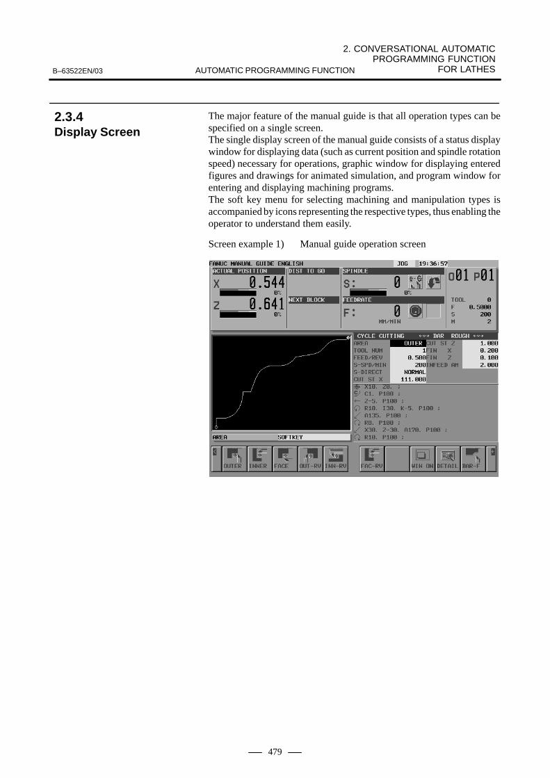
2. CONVERSATIONAL AUTOMATIC PROGRAMMING FUNCTION
FOR LATHESB–63522EN/03 AUTOMATIC PROGRAMMING FUNCTION
479
The major feature of the manual guide is that all operation types can bespecified on a single screen.The single display screen of the manual guide consists of a status displaywindow for displaying data (such as current position and spindle rotationspeed) necessary for operations, graphic window for displaying enteredfigures and drawings for animated simulation, and program window forentering and displaying machining programs.The soft key menu for selecting machining and manipulation types isaccompanied by icons representing the respective types, thus enabling theoperator to understand them easily.
Screen example 1) Manual guide operation screen
2.3.4Display Screen

2. CONVERSATIONAL AUTOMATIC PROGRAMMING FUNCTION FOR LATHES B–63522EN/03AUTOMATIC PROGRAMMING FUNCTION
480
When machining data is entered, a window is displayed on the screen asrequired.
Screen example 2) Window for entering data for displayedinstruction–based machining
The same screen can also be used for solid model–based machiningsimulation.
Screen example 3) Machining simulation

2. CONVERSATIONAL AUTOMATIC PROGRAMMING FUNCTION
FOR LATHESB–63522EN/03 AUTOMATIC PROGRAMMING FUNCTION
481
A list of created and registered machining programs can be displayed ina window.
Screen example 4) Program list window
The instructions for measuring workpiece end face positions required insetting up lathing are also displayed in a window.
Screen example 5) Window for displaying instructions for workpieceend face measurement

3. CONVERSATIONAL AUTOMATIC PROGRAMMING FUNCTION FOR MACHINING CENTERS B–63522EN/03AUTOMATIC PROGRAMMING FUNCTION
482
3 CONVERSATIONAL AUTOMATIC PROGRAMMINGFUNCTION FOR MACHINING CENTERS
Super CAPi M and MANUAL GUIDE are provided as the conversationalautomatic programming function for machining centers. As with SuperCAPi T and Super CAPi M use a machining process selection method forinput.
With the manual guide, widely used G code programs can be createdeasily by selecting menu items with pictorial representations.
For the 160i/180i/210i, use the CNC screen display function.For the 160is/180is/210is, this function is unavailable.
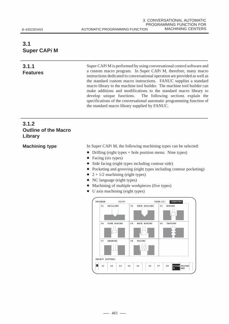
3. CONVERSATIONAL AUTOMATIC PROGRAMMING FUNCTION FOR
MACHINING CENTERSB–63522EN/03 AUTOMATIC PROGRAMMING FUNCTION
483
Super CAPi M is performed by using conversational control software anda custom macro program. In Super CAPi M, therefore, many macroinstructions dedicated to conversational operation are provided as well asthe standard custom macro instructions. FANUC supplies a standardmacro library to the machine tool builder. The machine tool builder canmake additions and modifications to the standard macro library todevelop unique functions. The following sections explain thespecifications of the conversational automatic programming function ofthe standard macro library supplied by FANUC.
In Super CAPi M, the following machining types can be selected:
� Drilling (eight types + hole position menu: Nine types)� Facing (six types)� Side facing (eight types including contour side)� Pocketing and grooving (eight types including contour pocketing)� 2 + 1/2 machining (eight types)� NC language (eight types)� Machining of multiple workpieces (five types)� U axis machining (eight types)
01 02 03 04 05
PROGRAM O1000 PAGE:01/ CREATING
SELECT SOFTKEY.
<
01 DRILLING 02 PECK DRILING 03 BORING
04 FINE BORING 04 BACK BORING 06 TAPPING
07 REAMING 08 FACING
06 07 08 GUIDAN PROCESCE END
3.1Super CAPi M
3.1.1Features
3.1.2Outline of the MacroLibrary
Machining type

3. CONVERSATIONAL AUTOMATIC PROGRAMMING FUNCTION FOR MACHINING CENTERS B–63522EN/03AUTOMATIC PROGRAMMING FUNCTION
484
An easy–to–understand guide figure and message are displayed for eachinput item on the screen.
F.S PROCESAUTO WINDOW
<
PROGRAM O1000 PAGE:01/ CREATING MAX NUM.OF TOOLS–10
NO. CYCLE PROCESS TOOL NAME001 AUXILIARY INITAL SETING002 FACING FACING PREP. FACE MIL
FACING PREP. FACE MILFACING SQUARE BIDIR
PROCESS END
HOLE :TAPPINGGROUP COPY :YB= UNUSED RETURN POINT: I=WK SURFACE : B= FEEDRATE CHG:YC= UNCHANGETAP DEPTH : V= KIND OF TAP : A= NORMALCHAMFER DIA : C= TOOL ID NO. : T=INPUT THE Z COORD OF THE UPPER SURFACE OF THE WORKPIECE.
TOOL GUIDAN INPUTINFOM CE END
Tool data, cutting condition data, and pre–tool data can be input easily byfollowing the instructions displayed on the screen.Once data is input, necessary data for machining is determinedautomatically.
HOLE :TAPPINGGROUP COPY :YB= UNUSED RETURN POINT: I=WK SURFACE : B= 0. FEEDRATE CHG:YC= UNCHANGETAP DEPTH : V= 20. KIND OF TAP : A= NORMALCHAMFER DIA : C= TOOL ID NO. : T= 25.INPUT THE TOOL ID NUMBER OF THE TOOL TO BE USED.
F.S. WINDOWAUTO CHANCE
PROGRAM O1000 PAGE:01/ CREATING
NO. CYCLE P001 AUXILIARY I002 FACING F
FFACING S
P
<
CUTTING DATA1/2 PROCESS4 PROCESS3 PROCESS2 PROCESS1TOOL ID NO.T= 25. 14. 12. 3.TOOL NAME Q= TAP DRILL DRILL CENT DRILLTOOL DTA E= 10. 8. 4. 3.H OFFSET NO. H= 125. 114. 112. 103.R POINT R= 10. 3. 3. 3.Z POINT Z= -20. -29.6 -24.8 -3.DWELL D= 0. 0. 0. 0.COOLANT M=COOLNT M7 COOLNT M7 COOLNT M7 COOLNT M7SPINDL SPEED S= 254. 3180. 5000. 4240.FEED RATE F= 280. 318. 50. 42.SPEED OFFST YD= * * * *SPEED CHG PT YE= * * * *PITCH J= 1.1 * * *
TOOL GUIDAN INPUTINFORMCE END
Conversational programinput screen
Tool/cutting condition/pre–tool automaticdetermination

3. CONVERSATIONAL AUTOMATIC PROGRAMMING FUNCTION FOR
MACHINING CENTERSB–63522EN/03 AUTOMATIC PROGRAMMING FUNCTION
485
Input data is indicated graphically, and so checking can be doneimmediately. If a data value exceeds an allowable limit, an alarm messageappears on the screen and the cursor appears at the position of the data inquestion.
PROGRAM O1000 PAGE:01/ CREATING
NO. CYCLE PROCESS TOOL NAME001 AUXILIARY INITAL SETING002 FACING FACING PREP. FACE MIL
FACING PREP. FACE MILFACING SQUARE BIDIR
PROCESS END003 HOLE TAPPING CENTER D
TAPPING DRILL TAPPING DRILL TAPPING TAP
HOLE PATTERN :PARALLELOGRMCOORDINATES :W= V LENGTH :V= 75. O V ANGLE : C= 90.X CO–ORD :X= 0. U NUMBER :D= 3. OMIT POINT 1 :YF= *Y–CO–ORD :Y= 0. V NUMBER :E= 2. OMIT POINT 2 :YG= *U LENGTH :U= 75. X–U ANGLE :A= 0. OMIT POINT 3 :YH= *
RETURN
Operations with Super CAPi M always begin with the following basicmenu screen. When the leftmost soft key on a conversational screenis pressed, the display is returned to the previous screen.
PROGRAM MAKE OR EDIT
1 2 3 4 5 6
OPTIMUM PROGRAM
PROGRAM CHECK
CONVERT NC FORMAT
C.A.P. DATA
7 8 9<
SUPER C.A.P.M
MEM MEM
MODE MODE
Immediate checking ofinput data
3.1.3Outline of theConversationalAutomaticProgramming Function
Basic menu screen
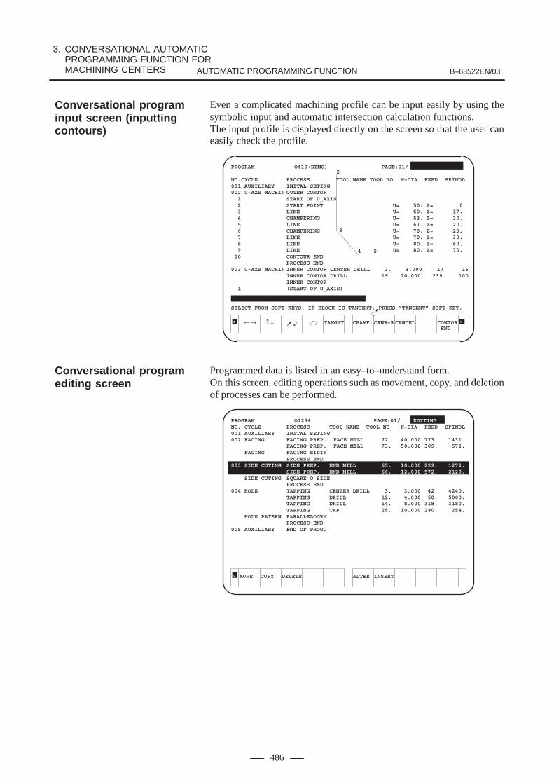
3. CONVERSATIONAL AUTOMATIC PROGRAMMING FUNCTION FOR MACHINING CENTERS B–63522EN/03AUTOMATIC PROGRAMMING FUNCTION
486
Even a complicated machining profile can be input easily by using thesymbolic input and automatic intersection calculation functions.The input profile is displayed directly on the screen so that the user caneasily check the profile.
← → ↑ ↓ TANGNT
PROGRAM O410(DEMO) PAGE:01/
NO.CYCLE PROCESS TOOL NAME TOOL NO N–DIA FEED SPINDL001 AUXILIARY INITAL SETING002 U–AXS MACHIN OUTER CONTOR 1 START OF U_AXIS 2 START POINT U= 50. Z= 0 3 LINE U= 50. Z= 17. 4 CHAMFERING U= 53. Z= 20. 5 LINE U= 67. Z= 20. 6 CHAMFERING U= 70. Z= 23. 7 LINE U= 70. Z= 30. 8 LINE U= 80. Z= 60. 9 LINE U= 80. Z= 70. 10 CONTOUR END
PROCESS END003 U–AXS MACHIN INNER CONTOR CENTER DRILL 3. 3.000 17 16
INNER CONTOR DRILL 19. 20.000 239 100INNER CONTOR
1 (START OF U_AXIS)
SELECT FROM SOFT–KEYS. IF BLOCK IS TANGENT, PRESS “TANGENT” SOFT–KEY.
< +
2
3
4 5
6
CHAMF.CRNR–R CANCEL CONTOREND
Programmed data is listed in an easy–to–understand form.On this screen, editing operations such as movement, copy, and deletionof processes can be performed.
MOVE COPY DELETE
PROGRAM O1234 PAGE:01/ EDITINGNO. CYCLE PROCESS TOOL NAME TOOL NO N–DIA FEED SPINDL001 AUXILIARY INITAL SETING002 FACING FACING PREP. FACE MILL 72. 40.000 773. 1431.
FACING PREP. FACE MILL 73. 50.000 309. 572.FACING FACING BIDIR
PROCESS END003 SIDE CUTING SIDE PREP. END MILL 65. 10.000 229. 1272.
SIDE PREP. END MILL 66. 12.000 572. 2120.SIDE CUTING SQUARE O SIDE
PROCESS END004 HOLE TAPPING CENTER DRILL 3. 3.000 42. 4240.
TAPPING DRILL 12. 4.000 50. 5000.TAPPING DRILL 14. 8.000 318. 3180.TAPPING TAP 25. 10.000 280. 254.
HOLE PATERN PARALLELOGRMPROCESS END
005 AUXILIARY FND OF PROG.
< ALTER INSERT
Conversational programinput screen (inputtingcontours)
Conversational programediting screen

3. CONVERSATIONAL AUTOMATIC PROGRAMMING FUNCTION FOR
MACHINING CENTERSB–63522EN/03 AUTOMATIC PROGRAMMING FUNCTION
487
The machining order can be changed automatically to reduce the numberof times tools are changed. The machining order can also be specifiedmanually.With these functions, the time required for machining can be reduced.
Process (1)
φ5 center drillingφ10 drilling
φ5 center drillingφ6.8 drillingφM8 tapping
φ5 center drillingφ7 drilling
Optimized program
φ5 center drilling of Process(1)φ5 center drilling of Process(2)φ5 center drilling of Process(3)φ10 drilling of Process(1)φ6.8 drilling of Process(2)φM8 tapping of Process(2)φ7 drilling of Process(3)
Automatic process alterationProcess (2)
Process (3)
Machining profiles, tool figures, and tool paths can be drawn in theisometric mode, biplane drawing mode, and so forth.In addition, an animated simulation function is provided to display a soliddrawing of the workpiece figure to be machined.
PATH GRAPHIC (EXECUTION)X 0.000Y 0.000Z 0.000
MEM **** *** *** 16:16:05
PATH GRAPH ROTA–GRAPH PARAM TION
<
01234 N01000
Z
Y
X
3-PLAN DRAWSTART
Process optimizationedit function
Full graphic function

3. CONVERSATIONAL AUTOMATIC PROGRAMMING FUNCTION FOR MACHINING CENTERS B–63522EN/03AUTOMATIC PROGRAMMING FUNCTION
488
A machining program created conversationally can be run directly. Theprogram can also be converted and then executed as an NC program form.Furthermore, when modifications are made to the NC program obtainedby the conversion, a more efficient machining program can be created.
RETURN
PATH GRAPHIC (EXECUTION)CONVERT NC FORMAT
X –65.000Y 40.000Z 3.000
F 500.000S 5000T 15
MACHINING TIME 34.500:06:21
PRESS RETURN SOFTKEY MEM **** *** *** 11:21:05
<
O1234 N01234
Z
Y
X
O2000→O2001G04X0.;G00Z3.;X–65.Y40.;G90Z3.;F500.;G01Z–22.;G04X0.;G00Z3.;G52X0.Y0.Z0.;M30;
In programming for an arbitrary figure, a certain section of a figure canbe repeated more than once. Three types of repetitions are available:Inversion, rotation, and parallel displacement. By combining these types,program data can be utilized more than once in a program.
GUIDAN INPUTCE END
PROGRAM 01000 PAGE :01/ CREATING
NO. CYCLE PROCESS TOOL NAME001 INITIAL SETING002 SIDE CUTING CONTOR PREP. END MILL 1 START POINT X= –30.0 2 APPROACII X= 0 3 → X= 100.0 4 ↑ X= 100.0 5 CORNER R R= 30.0 6 → X= 200.0
CONTOUR FORM (ROTATION COPY)NO. OF REPEAT : R=CENTER X : X=CENTER Y : Y=ANGLE K : K=
<
R2 R1END PT.
START PT.
K
X
Y
(X, Y)
3.1.4Other OptionalFunctions
NC program outputfunction
Contour repeat function

3. CONVERSATIONAL AUTOMATIC PROGRAMMING FUNCTION FOR
MACHINING CENTERSB–63522EN/03 AUTOMATIC PROGRAMMING FUNCTION
489
A machining program can be created and checked using the drawingfunction while another program is being executed for machining.By using this function, the NC can be used more efficiently.
SINGLESTOPOFF
PATH GRAPHIC (EXECUTION)
X –100.000Y 52.000Z 10.000
50.4
MEM STRT *** *** 17:44:23 DRAWING
<
O1234 NO1234
Z
YX
Programs for the following cutting operations with the lathe can be inputconversationally:
� Contouring (outer surface/inner surface/end face)
� Grooving (outer surface/inner surface/end face)
� Threading (external/internal)
06 07 08 GUIDAN PROCESCE END
01 02 03 04 05
PROGRAM O4008(DEMO) PAGE :01/ EDITING
SELECT FROM SOFT–KEYS.
<
01 OUTER CONTOR 02 INTER CONTOR 03 FACE CONTOR
04 OUTER GROOVE 04 INNER GROOVE 06 FACE GROOVE
07 OUTER THREAD 08 INNER THREAD
Background drawingfunction
U–axis conversationalfunction

3. CONVERSATIONAL AUTOMATIC PROGRAMMING FUNCTION FOR MACHINING CENTERS B–63522EN/03AUTOMATIC PROGRAMMING FUNCTION
490
In addition, simulation for the machining profile, removal, tool path, andothers functions are enabled during cutting.
SINGLESTOP 1BOLCKON EXEC.
PATH GRAPHIC (EXECUTION)
X 0.000Y 0.000Z 1.000U 9.000F 10.000S 100T 126
62.5
MEM STOP *** *** 14:56:57 STOP
O4010 N04010
Y
XZ
X
When a custom macro program is replaced with a program coded in C,programs such as those for automatic tool setting and automatic cuttingcondition setting can be executed at high–speed.Programs are developed on a personal computer.
Conversational Clanguage programmingfunction

3. CONVERSATIONAL AUTOMATIC PROGRAMMING FUNCTION FOR
MACHINING CENTERSB–63522EN/03 AUTOMATIC PROGRAMMING FUNCTION
491
By using the manual guide, the operator can perform many types ofmachining from simple handle–based cutting to complicated machiningas follows:
� Handle–based machining (optional)With the guidance handle, a tilt straight line and an arc can bemachined.Furthermore, these machining operations can be taught and stored ina form of machining programs for playback operation so that they canbe performed repeatedly.In addition, during playback operation, the guidance handlesynchronization feed function can be used to control the toolmovement.
� Canned–cycle machiningThe following canned cycles can be specified to automaticallyperform complicated machining:(1) Drilling(2) Drilling pattern(3) Facing(4) Side facing(5) Pocketing and grooving(6) Contouring
The manual guide has the following features for easily creatingcomplicated G code programs (ISO programs) in conversational mode:
1) Menu selection
The complicated G code system is systematically classified intoseveral menus so that the operator can select these G code menus tocreate G code programs easily.
2) Display of guidance diagrams and items in windows
According to the input data, appropriate guidance diagrams and itemsare displayed in windows as necessary to support operator’s input.
3) Checking of an entered program
After entering a program, the operator can check it easily throughmachining simulation. Since the machining program and tool path aredisplayed on the screen at the same time, the operator can check theentered program easily.
4) Easy operation by menus with pictorial representations
Soft keys with pictorial representations are used for all menu items, sothe operator can easily understand the menu items.
5) Many canned cycles
Canned cycles for milling such as drilling, side facing, and pocketingare prepared. The operator only needs to enter a desired G code; thencomplicated machining can be performed automatically.
3.2MANUAL GUIDE
3.2.1Features

3. CONVERSATIONAL AUTOMATIC PROGRAMMING FUNCTION FOR MACHINING CENTERS B–63522EN/03AUTOMATIC PROGRAMMING FUNCTION
492
A general procedure with the manual guide from preparation formachining to operation is shown below.
YesNo
Set parameters (usually unnecessary)
Set offset data
Start programming
Select O number
Menu selection
Guidance machining and teachingInput straight line, arc, and
auxiliary function Input cycle machining
End of programming?
Animated simulation
Program operation
MDI operation, manual operation
3.2.2Operation

3. CONVERSATIONAL AUTOMATIC PROGRAMMING FUNCTION FOR
MACHINING CENTERSB–63522EN/03 AUTOMATIC PROGRAMMING FUNCTION
493
The major feature of the manual guide is that all operations can bespecified on a single screen.The manual guide displays necessary information for a given operationon a single display screen that consists of windows such as a status displaywindow for displaying necessary data for the operation such as the currentposition and spindle speed, a graphic window for displaying enteredfigures and drawings for animated simulation, and a machining programwindow.The soft key menu for selecting machining and manipulation types isaccompanied by icons representing the respective types, thus enabling theoperator to understand them easily.
Screen example 1) Manual guide operation screen
3.2.3Display Screen

3. CONVERSATIONAL AUTOMATIC PROGRAMMING FUNCTION FOR MACHINING CENTERS B–63522EN/03AUTOMATIC PROGRAMMING FUNCTION
494
When machining data is entered, a pop–up window is displayed on thescreen as necessary.
Screen example 2) Window for entering drilled–position pattern data
Machining simulation with a solid model can also be performed on thesame screen.
Screen example 3) Machining simulation

3. CONVERSATIONAL AUTOMATIC PROGRAMMING FUNCTION FOR
MACHINING CENTERSB–63522EN/03 AUTOMATIC PROGRAMMING FUNCTION
495
A list of created and registered machining programs can be displayed ina window.
Screen example 4) Program list window
Handle–based guidance machining can also be performed on the samescreen.
Screen example 5) Window for guidance machining


IV. HAND CNC (Series 20i)

1. OUTLINE OF HAND CNC (Series 20i)B–63522EN/03 HAND CNC (Series 20i)
499
1 OUTLINE OF HAND CNC (Series 20i)
The Series 20i CNC has been developed for general purpose millingmachines and general–purpose lathes. These kind of general–purposemachine tools differ greatly from regular CNC machine tools. For thisreason, CNC units for controlling these machine tools are provided withmany exclusive functions. Generally a CNC unit developed exclusivelyfor these kind of general–purpose machine tools is called a “hand CNC”to differentiate it from other CNC units.
The Series 20i has a machining guidance function that does not use NCstatement programs as an exclusive function for general–purposemachine tools. This machining guidance function allows you to easilyperform a variety of machining processes as if you were operating ageneral–purpose machine without any special knowledge of CNC; all youneed to do is to set the minimum required data such as position data.
The machine tool builder can customize this function because it has beenimplemented using the macro executor.
If you install the optional guidance programming function, you can alsomake NC statement programs using menu selection. In addition to basicNC program statements, these menus are provided with patternmachining processes called “cycle machining.” For example, on theSeries 20i–F, you can easily execute complex machining such as planemachining or pocket machining.

Mac
hine
con
trol
led
axes
2. LIST OF SPECIFICATIONS B–63522EN/03HAND CNC (Series 20i)
500
2 LIST OF SPECIFICATIONS
FANUC Series 20i–TB CNC for manual lathes
FANUC Series 20i–FB CNC for manual milling machines
� : Standard � : Option� : Function included in another option— : Relevant function not available �: Standard option� : Standard function usable in machining guidance function
Or, standard specification usable in macro executor� : Option usable in machining guidance
Or, option usable in macro executor
Series 20i
TB FB
Item Specifications Guidance Programming or NC Program editing
Without With Without With
Controlled axis
Total Controlled axes2 axes � � — —
Total Controlled axes4 axes (Machine controlled axes) — — � �
Controlled path 1 path � � � �
Controlled axis2 axes � � — —
Controlled axis3 axes — — � �
Simultaneously controlled axesSimultaneous 2 axes � � — —
Simultaneously controlled axesSimultaneous 3 axes — — � �
Controlled axes expansion (total) Max. 4 axes — — � �
Axis control by PMC — — � �
Axis nameBasic 3 axes are X, Y and Z, additional axisis optional from U, V, W, A, B, C.
— — � �Axis name
Basic 2 axes are X, Z � � — —
Control axis detach — — � �
Chopping — — � �
Least input increment 0.001mm, 0.001deg, 0.0001inch � � � �
Increment system 1/10 *1 0.0001mm, 0.0001deg, 0.00001inch — — � �
Flexible feed gear Optional DMR � � � �
Fine Acc & Dec control � � � �
HRV control � � � �
High–speed HRV control Servo HRV3 control � � � �
Inch/metric conversion � � � �
Interlock All axes/each axis/each direction/block start/cutting block start
� � � �
Machine lock All axes/each axis � � � �
Emergency stop � � � �
Note) The items marked with *1 to *5 have notes added. These notes are provided at the end of this table.
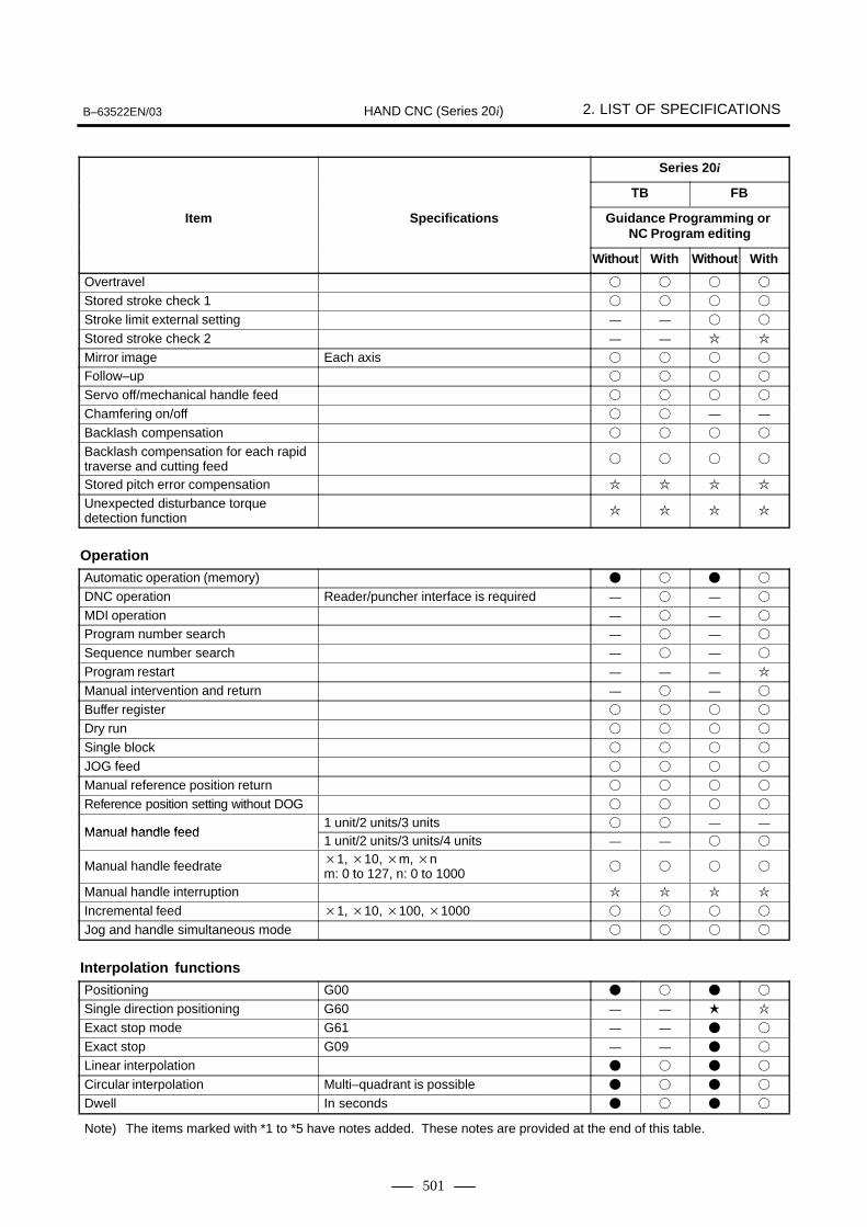
B–63522EN/03 2. LIST OF SPECIFICATIONSHAND CNC (Series 20i)
501
Series 20i
FBTB
Item Guidance Programming or NC Program editing
Specifications
WithWithoutWithWithout
Overtravel � � � �
Stored stroke check 1 � � � �
Stroke limit external setting — — � �
Stored stroke check 2 — — � �
Mirror image Each axis � � � �
Follow–up � � � �
Servo off/mechanical handle feed � � � �
Chamfering on/off � � — —
Backlash compensation � � � �
Backlash compensation for each rapidtraverse and cutting feed
� � � �
Stored pitch error compensation � � � �
Unexpected disturbance torque detection function
� � � �
Operation
Automatic operation (memory) � � � �
DNC operation Reader/puncher interface is required — � — �
MDI operation — � — �
Program number search — � — �
Sequence number search — � — �
Program restart — — — �
Manual intervention and return — � — �
Buffer register � � � �
Dry run � � � �
Single block � � � �
JOG feed � � � �
Manual reference position return � � � �
Reference position setting without DOG � � � �
Manual handle feed1 unit/2 units/3 units � � — —
Manual handle feed1 unit/2 units/3 units/4 units — — � �
Manual handle feedrate �1, �10, �m, �nm: 0 to 127, n: 0 to 1000
� � � �
Manual handle interruption � � � �
Incremental feed �1, �10, �100, �1000 � � � �
Jog and handle simultaneous mode � � � �
Interpolation functions
Positioning G00 � � � �
Single direction positioning G60 — — � �
Exact stop mode G61 — — � �
Exact stop G09 — — � �
Linear interpolation � � � �
Circular interpolation Multi–quadrant is possible � � � �
Dwell In seconds � � � �
Note) The items marked with *1 to *5 have notes added. These notes are provided at the end of this table.

2. LIST OF SPECIFICATIONS B–63522EN/03HAND CNC (Series 20i)
502
Series 20i
FBTB
Item Guidance Programming or NC Program editing
Specifications
WithWithoutWithWithout
Helical interpolation Circular interpolation plus max.2 axes linear interpolation *4
— — � �
Threading, synchronous cutting Position coder is necessary on the spindle � � � �
Multiple threading � � — —
Threading retract � � — —
Continuous threading *4 � � — —
Variable lead threading *4 � � — —
Skip G31 � � � �
High–speed skip — — � �
Torque limit skip � � — —
Reference position return G28 � � � �
Reference position return check G27 � � � �
2nd reference position return � � � �
Feed function
Rapid traverse rate Max. 240m (1µm) � � � �
Rapid traverse override F0, 25, 50, 100% � � � �
Feed per minute � � � �
Feed per revolution � � — —
Tangential speed constant control � � � �
Cutting feedrate clamp � � � �
Automatic acceleration/ deceleration Rapid traverse: linearCutting feed: exponential
� � � �
Linear acceleration/deceleration after cutting feed interpolation
� � � �
Bell–shaped acceleration/deceleration after cutting feed interpolation
� � � �
Feedrate override 0 to 254% � � � �
Jog override 0 to 655.34% � � � �
Override cancel � � � �
Manual per revolution feed � � — —
The stop position setting with the manual feed
� � — —
Advanced preview control — — � �
AI contour control — — — �
Program input
Tape code EIA RS244/ISO840Automatic recognition
� � � �
Label skip � � � �
Parity check Horizontal and vertical parity � � � �
Control in/out � � � �
Optional block skip 1 � � � �
Max. programmable dimension ±8 digit � � � �
Program number O4 digit � � � �
Sequence number N5 digit � � � �
Note) The items marked with *1 to *5 have notes added. These notes are provided at the end of this table.

B–63522EN/03 2. LIST OF SPECIFICATIONSHAND CNC (Series 20i)
503
Series 20i
FBTB
Item Guidance Programming or NC Program editing
Specifications
WithWithoutWithWithout
Absolute/incremental programming Combined use in the same block � � � �
Decimal point programming/pocket calculator type decimal point programming
� � � �
Input unit 10 time multiply — — � �
Diameter/radius programming (X axis) � � — —
Plane selection G17, G18, G19 — — � �
Rotary axis designation — — � �
Rotary axis roll–over — — � �
Coordinate system setting � � � �
Automatic coordinate system setting � � � �
Coordinate system shift � � — —
Direct input of coordinate system shift � � — —
Workpiece coordinate system G52, G53, G54 to G59 — — � �
Workpiece coordinate system preset *4 — — � �
Manual absolute on and off � � � �
G code system A � � — —
G code system B/C � � — —
Chamfering/corner R � � — —
Optional chamfering/corner R *4 — — � �
Programmable data input G10 � � � �
Sub program call 4 folds nested � � � �
Custom macro B � � � �
Interruption type custom macro � � — —
Canned cycles � � — —
Multiple repetitive cycle *5 — � — —
Multiple repetitive cycle II Pocket profile *5 — � — —
Canned cycles for drilling — — � �
Circular interpolation by R programming � � � �
Automatic corner override *4 — — � �
Scaling *4 — — � �
Coordinate system rotation *4 — — � �
Programmable mirror image *4 — — � �
Macro executor A Max. 1.5 MB (Including machining guidance) � � � �
Additional custom memory 0.5 MB In addition to macro executor A, Max. 2 MB is available.
� — � —
Additional custom memory 1 MB In addition to macro executor A, Max. 2.5 MB is available.
— � — �
Additional custom memory 1.5 MB In addition to macro executor A, Max. 3 MB is available.
� — � —
Machining guidance function � � � �
Guidance programming function *2 — � — �
NC program editing function *2 � � � �
Note) The items marked with *1 to *5 have notes added. These notes are provided at the end of this table.
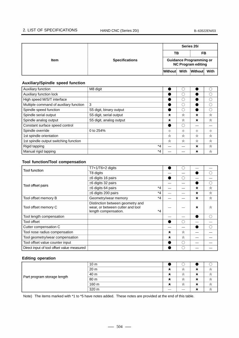
2. LIST OF SPECIFICATIONS B–63522EN/03HAND CNC (Series 20i)
504
Series 20i
FBTB
Item Guidance Programming or NC Program editing
Specifications
WithWithoutWithWithout
Auxiliary/Spindle speed function
Auxiliary function M8 digit � � � �
Auxiliary function lock � � � �
High speed M/S/T interface � � � �
Multiple command of auxiliary function 3 � � � �
Spindle speed function S5 digit, binary output � � � �
Spindle serial output S5 digit, serial output � � � �
Spindle analog output S5 digit, analog output � � � �
Constant surface speed control � � — —
Spindle override 0 to 254% � � � �
1st spindle orientation � � � �
1st spindle output switching function � � � �
Rigid tapping *4 — — � �
Manual rigid tapping *4 — — � �
Tool function/Tool compensation
Tool functionT7+1/T6+2 digits � � — —
Tool functionT8 digits — — � �
Tool offset pairs
±6 digits 16 pairs � � — —
Tool offset pairs±6 digits 32 pairs — — � �
Tool offset pairs±6 digits 64 pairs *4 — — � �
±6 digits 200 pairs *4 — — � �
Tool offset memory B Geometry/wear memory *4 — — � �
Tool offset memory CDistinction between geometry and wear, or between cutter and tool length compensation. *4
— — � �
Tool length compensation — — � �
Tool offset � � — —
Cutter compensation C — — � �
Tool nose radius compensation � � — —
Tool geometry/wear compensation � � — —
Tool offset value counter input � � — —
Direct input of tool offset value measured � � — —
Editing operation
Part program storage length
10 m � � � �
Part program storage length
20 m � � � �
Part program storage length40 m � � � �
Part program storage length80 m � � � �
160 m � � � �
320 m — — � �
Note) The items marked with *1 to *5 have notes added. These notes are provided at the end of this table.

B–63522EN/03 2. LIST OF SPECIFICATIONSHAND CNC (Series 20i)
505
Series 20i
FBTB
Item Guidance Programming or NC Program editing
Specifications
WithWithoutWithWithout
Number of registerable programs63 � � � �
Number of registerable programs 125 — — � �Number of registerable programs200 — — � �
Part program editing — � — �
Program protect — � — �
Background editing — � — �
Extended part program editing Available in NC program editing function only — � — �
Playback — � — �
Setting and displayStatus display � � � �
Clock function � � � �
Current position display � � � �
Program display Program name 16 characters — � — �
Parameter setting and display � � � �
Self–diagnosis function � � � �
Alarm display � � � �
Alarm history display � � � �
Operation history display � � � �
Help function � � � �
Remote diagnostic Machine remote diagnosis package+Ethernet(Function:Reading CNC/PMC status, etc.)
� � � �
Run hour and parts count display � � � �
Actual cutting feedrate display � � � �
Display of spindle speed and T code atall screens
� � � �
Directory display of floppy cassette — � — �
Directory display and punch for each group
— � — �
Graphic function � � � �
Dynamic graphic display — � — �
Servo setting screen � � � �
Spindle setting screen Only for serial interface � � � �
Servo waveform display � � � �
Display of hardware and software configuration
� � � �
Periodic maintenance screen � � � �
Maintenance information screen � � � �
Software operator’s panel � � � �
Software operator’s panel general purpose switch
� � � �
External touch panel interface It is impossible to use with the Touch panel — — � �
Note) The items marked with *1 to *5 have notes added. These notes are provided at the end of this table.

2. LIST OF SPECIFICATIONS B–63522EN/03HAND CNC (Series 20i)
506
Series 20i
FBTB
Item Guidance Programming or NC Program editing
Specifications
WithWithoutWithWithout
Multi–language display
English � � � �
Multi–language display
Japanese (Chinese character) � � � �
Multi–language displayGerman/French � � � �
Multi–language display Italian � � � �Multi–language displayChinese � � � �
Spanish � � � �
Korean � � � �
Data protection key � � � �
Erase LCD screen display � � � �
Data input/output
Reader/puncher interfaceReader/puncher (Ch.1) interface � � � �
Reader/puncher interfaceReader/puncher (Ch.2) interface � � � �
Remote buffer — — — �
External I/O device control � � � �
Modem card control � � � �
External data input � � � �
External key input � � � �
External program input — � — �
External workpiece number search 15 — � — �
Memory card input/output — � — �
Screen hard copy � � � �
Power Mate CNC manager � � � �
Interface function
Embedded Ethernet � � � �
Fast Ethernet Fast Ethernet board is required. � � � �
Machining guidance functionLine/Circle cutting � � � �
Corner cutting � � � �
Pocketing Circle, Square, Track — — � �
Pattern positioning Circle, Square, Grid, Random — — � �
Hole machining Drilling, Center, Tapping *3 � � � �
Side cutting Circle, Square, Track — — � �
Limit machining Square limited area — — � �
Polygonal limited cutting Convex polygon with maximum 6 corner — — � �
Rough machining Maximum 28 points (only TB) � � � �
Facing — — � �
Threading � � — —
Grooving Normal, Trapezoid � � — —
Tool compensation — — � �
–X area cutting � � — —
Note) The items marked with *1 to *5 have notes added. These notes are provided at the end of this table.
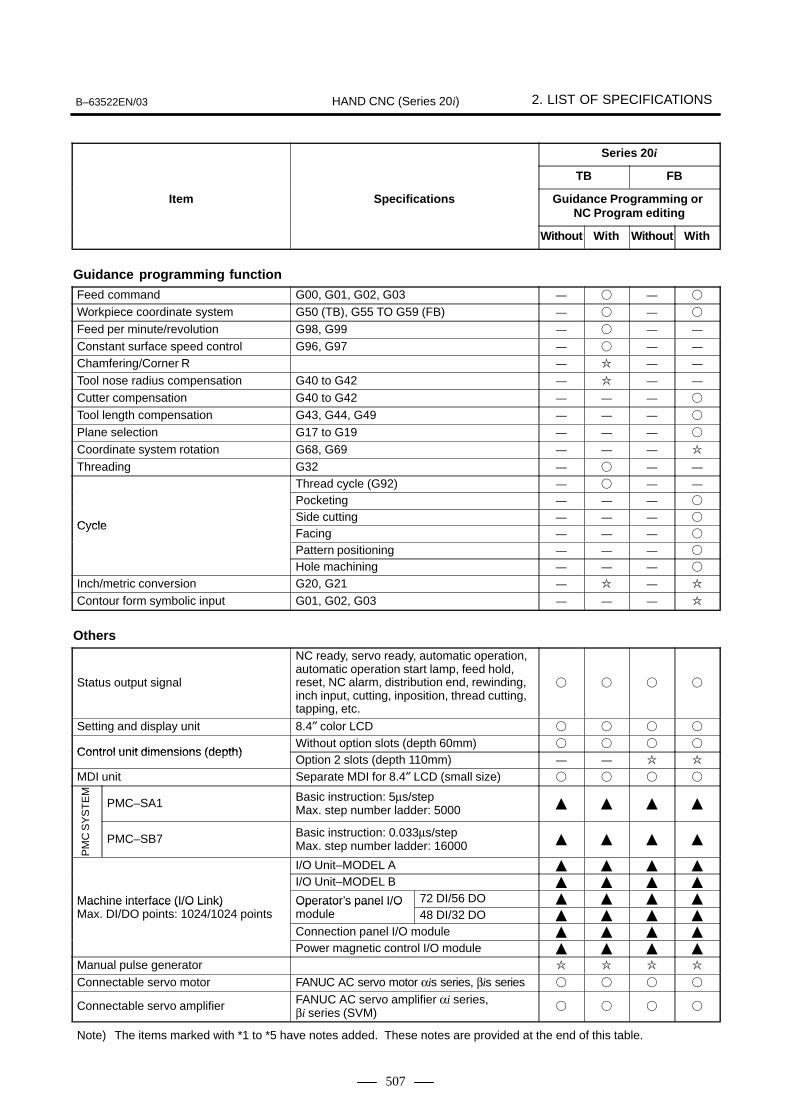
PM
C S
YS
TE
M
B–63522EN/03 2. LIST OF SPECIFICATIONSHAND CNC (Series 20i)
507
Series 20i
FBTB
Item Guidance Programming or NC Program editing
Specifications
WithWithoutWithWithout
Guidance programming function
Feed command G00, G01, G02, G03 — � — �
Workpiece coordinate system G50 (TB), G55 TO G59 (FB) — � — �
Feed per minute/revolution G98, G99 — � — —
Constant surface speed control G96, G97 — � — —
Chamfering/Corner R — � — —
Tool nose radius compensation G40 to G42 — � — —
Cutter compensation G40 to G42 — — — �
Tool length compensation G43, G44, G49 — — — �
Plane selection G17 to G19 — — — �
Coordinate system rotation G68, G69 — — — �
Threading G32 — � — —
Cycle
Thread cycle (G92) — � — —
Cycle
Pocketing — — — �
CycleSide cutting — — — �
CycleFacing — — — �
Pattern positioning — — — �
Hole machining — — — �
Inch/metric conversion G20, G21 — � — �
Contour form symbolic input G01, G02, G03 — — — �
Others
Status output signal
NC ready, servo ready, automatic operation,automatic operation start lamp, feed hold,reset, NC alarm, distribution end, rewinding,inch input, cutting, inposition, thread cutting,tapping, etc.
� � � �
Setting and display unit 8.4″ color LCD � � � �
Control unit dimensions (depth)Without option slots (depth 60mm) � � � �
Control unit dimensions (depth)Option 2 slots (depth 110mm) — — � �
MDI unit Separate MDI for 8.4″ LCD (small size) � � � �
PMC–SA1 Basic instruction: 5µs/step Max. step number ladder: 5000
� � � �
PMC–SB7 Basic instruction: 0.033µs/step Max. step number ladder: 16000
� � � �
Machine interface (I/O Link)
I/O Unit–MODEL A � � � �
Machine interface (I/O Link)
I/O Unit–MODEL B � � � �
Machine interface (I/O Link) Max. DI/DO points: 1024/1024 points
Operator’s panel I/O module
72 DI/56 DO � � � �Machine interface (I/O Link) Max. DI/DO points: 1024/1024 points
Operator’s panel I/O module 48 DI/32 DO � � � �Max. DI/DO points: 1024/1024 points
Connection panel I/O module � � � �
Power magnetic control I/O module � � � �
Manual pulse generator � � � �
Connectable servo motor FANUC AC servo motor αis series, βis series � � � �
Connectable servo amplifier FANUC AC servo amplifier αi series, βi series (SVM)
� � � �
Note) The items marked with *1 to *5 have notes added. These notes are provided at the end of this table.

2. LIST OF SPECIFICATIONS B–63522EN/03HAND CNC (Series 20i)
508
Series 20i
FBTB
Item Guidance Programming or NC Program editing
Specifications
WithWithoutWithWithout
Separate position detector for full–closed control (for full–closed control)
Separate pulse coder/optical scale (2–phase pulse interface)
� � � �Separate position detector for full–closed control (for full–closed control) Separate pulse coder/optical scale
(Serial interface)� � � �
Connectable spindle motor FANUC AC spindle motor αi series � � � �
Connectable spindle amplifierFANUC servo amplifier αi series � � � �
Connectable spindle amplifierAnalog interface � � � �
SERVO GUIDE � � � �
Input power supply DC24V±10% � � � �
Temperature around unit At operating: 0�C to 58�CAt non operating: –20�C to 60�C
� � � �
Ambient relative humidity
Normally: less than 75%Normally: No dew, nor frost allowedShort term (within one month)Normally: less than 95%Normally: No dew, nor frost allowed
� � � �
Vibration At operating: less than 0.5GAt non operating: less than 1G
� � � �
Note) The items marked with *1 to *5 have notes added. These notes are provided at the end of this table.
NOTE1 The FANUC standard machining guidance function and guidance programming function do not
support setting unit IS–C. This setting unit can be supported by remodeling by the machine toolmanufacturer.
2 Parameter settings allows you to enable or disable display of the NC program editing screen.There are two editing methods:� Editing by guidance programming (option)� Editing by NC languageThe following four methods of use are possible by setting options and parameters.

B–63522EN/03 2. LIST OF SPECIFICATIONSHAND CNC (Series 20i)
509
Guidance program function (w/ options)
Guidance program function (w/out options)
Parameter No.9320#6(NPR)=0
Parameter No.9320#6(NPR)=1Parameter No.9320#6(NPR)=1
(1) (2) (3) (4)
Parameter No.9320#6(NPR)=0
(1)“Guidance programming function” onlyExactly the same method of use as the “guidance programmingfunction” on the Series 20–FB/TB is possible by setting parameterNo.9320#6(NPR) to “0” when the “guidance programming function”(option) is not added on.
Guidance programming screen Machining guidance screen
CUSTOM
PROG
In this case, the CNC language screen can be displayed by pressing the[NC language] soft key, and programs can be edited or made in thisscreen. However, screen functions are limited and some functions suchas the extended part program editing function cannot be used.
(2)“Guidance programming function” + “NC program editing function”You can use both the same NC program editing screen and theguidance programming function as other CNCs (e.g. Series 21i) bysetting parameter No.9320#6(NPR) to “0” when the “guidanceprogramming function” (option) is not added on.

2. LIST OF SPECIFICATIONS B–63522EN/03HAND CNC (Series 20i)
510
Guidance programming screen Machining guidance screen
CUSTOM
PROG
[Interactive] [NC language]
Guidance programming screenfunction menu screen
(no program list screen)
In this case, the program list screen in the guidance programmingfunction cannot be used. However, the extended part program editingfunction can be used by adding on options.Also, NC program conversion can be selected for machining programsthat have been made using the guidance programming function byusing [NC conversion] displayed in the function menu screen of theguidance programming screen. In this case, the program currentlydisplayed at that time is converted to an NC program.
(3)“NC program editing function” onlyYou can display the same NC program editing screen as other CNCs(e.g. Series 21i) and make and edit NC programs in that screen bysetting parameter No.9320#6(NPR) to “0” when the “guidanceprogramming function” (option) is not added on.
NC program editing screen Machining guidance screen
CUSTOM
PROG
(4)W/out CNC program editing functionWhen the “guidance programming function” (optional) is not addedon, and parameter No.9320#6(NPR) is set to “0”, CNC programscannot be edited or made.
Machining guidance screen

B–63522EN/03 2. LIST OF SPECIFICATIONSHAND CNC (Series 20i)
511
NOTE3 In drilling using the machining guidance function for a lathe,
only drilling can be used.4 The FANUC standard machining guidance function and
guidance programming function do not support thesefunctions. The machining guidance function can besupported by remodeling by the machine tool manufacturer.
5 This function cannot be used on the machining guidancefunction and macro executor.

3. MACHINING GUIDANCE FUNCTION B–63522EN/03HAND CNC (Series 20i)
512
3 MACHINING GUIDANCE FUNCTION
� In addition to manual operation, this function allows you to easilymachine complex shapes such as inclined straight lines or arc byoperation like that on the control panel of a general–purpose millingmachine.
� This function is provided as a FANUC standard function. However,the machine tool builder can customize the function because it hasbeen prepared in the form of a macro program using the macroexecutor.
� During machining in manual operation, select the machining methodfrom the machining guidance menu, enter the required data andmachine the desired profile.
� Position data can be input by numerical value keys or moving the toolby the handle and pressing buttons.
� The following machining menus are provided as basic functions:
1) Linear machining
2) Circular machining
3) Corner machining
4) Pocket machining (circle, square, track)
5) Pattern positioning (circle, square, grid, arbitrary)
� The following machining menus are optional:
1) Drilling (drill, center, tap)
2) Side machining (circle, square, track)
3) Limit machining (square profile limit)
4) Polygon limit machining (polygons up to convex hexagons)
5) Roughing
6) Plane machining
7) Tool offset function
� For details of the machining guidance function, refer to the “Series20i–FA/20i–FB Machining Guidance Function Operator’s Manual(B–62174E–1).”
Series 20i–FB MachiningGuidance Function

3. MACHINING GUIDANCE FUNCTIONB–63522EN/03 HAND CNC (Series 20i)
513
Screen example 1) Linear machining
Screen example 2) Tapping
Screen example 3) Polygon limit machining

3. MACHINING GUIDANCE FUNCTION B–63522EN/03HAND CNC (Series 20i)
514
� In addition to manual operation, this function allows you to easilymachine complex shapes such as inclined straight lines or arc byoperation like that on the control panel of a general–purpose millingmachine.
� This function is provided as a FANUC standard function. However,the machine tool builder can customize the function because it hasbeen prepared in the form of a macro program using the macroexecutor.
� During machining in manual operation, select the machining methodfrom the machining guidance menu, enter the required data andmachine the desired profile.
� Position data can be input by numerical value keys or moving the toolby the handle and pressing buttons.
� The following machining menus are provided as basic functions:
1) Linear machining
2) Circular machining
3) Corner machining
4) Drilling (drill)
5) Roughing (max. 28 points)
6) Roughing
7) Groove cutting (regular groove, trapezoidal groove)
� The following machining menu is optional:
1) XW/ X minus area switching function
� For details of the machining guidance function, refer to the “Series20i–TA/TB Machining Guidance Function Operator’s Manual(B–62204E–1).”
Screen example 1) Circular machining
Series 20i–TB MachiningGuidance Function

3. MACHINING GUIDANCE FUNCTIONB–63522EN/03 HAND CNC (Series 20i)
515
Screen example 2) Thread cutting
Screen example 3) Groove cutting

4. GUIDANCE PROGRAMMING FUNCTION B–63522EN/03HAND CNC (Series 20i)
516
4 GUIDANCE PROGRAMMING FUNCTION
� This function allows you to easily create or edit NC statementmachining programs by means of menu selection. This function isoptional on the Series 20i as it is a hand CNC developed forgeneral–purpose machine–tools that do not use NC statementmachining programs.
� This function is supplied as a FANUC standard function. Its contentscannot be modified.
� The following menus are provided for the Series 20i–F:
1) Feed instruction (G00, G01, G02, G03)
2) Coordinate system (G55 to G59)
3) Cutter compensation (G40 to G42)
4) Tool length compensation (G43, G44, G49)
5) Plane selection (G17 to G19)
6) Coordinate system rotation (G68, G69: optional NC functionrequired)
7) Inch/metric conversion (G20, G21: optional NC function required)
8) Plane machining (square plane)
9) Drilling (drill, center, tap, boring)
10) Drilling pattern position (circle periphery, arc, square, grid,arbitrary)
11) Side machining (outer side of circle, inner side of circle, outer sideof square, outer side of track)
12) Pocket machining (circle, square, track)
� The following menus are provided on the Series 20i–T:
1) Feed instruction (G00, G01, G02, G03)
2) Coordinate system (G50)
3) Constant surface speed control (G96, G97)
4) MAIW/N feed per revolution (G98, G99)
5) Chamfering/Corner R (optional NC function required)
6) Tool nose radius compensation (G40, G42: optional NC functionrequired)
7) Thread cutting (G32, G92)
8) Inch/metric conversion (G20, G21: optional NC function required)

4. GUIDANCE PROGRAMMING FUNCTIONB–63522EN/03 HAND CNC (Series 20i)
517
Screen example 1) Feed instruction (Series 20i–F)
Screen example 2) Drilling pattern position (Series 20i–F)
Screen example 3) Pocket machining (track) data input screen (Series 20i–F)

4. GUIDANCE PROGRAMMING FUNCTION B–63522EN/03HAND CNC (Series 20i)
518
Screen example 4) Screen example 4) Program list screen (Series 20i–T)
Screen example 5) Thread cutting menu (Series 20i–T)
Screen example 6) Corner radius data input screen (Series 20i–T)

B–63522EN/03 5. NC FUNCTIONS OF 20iHAND CNC (Series 20i)
519
5 NC FUNCTIONS OF 20i
This chapter describes the NC functions specific to the Series 20i. For anexplanation of the other NC functions, see Part II.

5. NC FUNCTIONS OF 20i B–63522EN/03HAND CNC (Series 20i)
520
This function allows you to rotate up to three manual pulse (T series) orup to four manual pulse generators (F series) and move the tool over thedistance corresponding to the rotation. The function also allows you toset a magnification for each manual pulse generator.
5.1MANUAL HANDLE FEED

B–63522EN/03 5. NC FUNCTIONS OF 20iHAND CNC (Series 20i)
521
The function selection soft keys are intended to select screens. Theirfunctions are equivalent to those of the function keys. For example,pressing function selection soft key [ POS ] selects the same screen that
is selected using the POS function key.
The function selection soft keys are displayed when bit 0 of parameter No.3101 (FSK) is 0. They are not displayed when the bit is 1.
The following function selection keys are available.
[ POS ] [PRGRM] [SETING] [SYSTEM] [(CHAP)]
[ MSG ] [ ] [CUSTOM] [ ] [(CHAP)]
The following table lists the function selection soft keys and thecorresponding function keys.
Function selection soft key Corresponding function key
[ POS ] POS
[PRGRM] PROG
[SETING] OFFSETSETTING
[SYSTEM] SYSTEM
[ MSG ] MSG
[CUSTOM] CUSTOMGRAPH
Pressing soft key ([CHAP]) displays the chapter selection soft keys.
5.2FUNCTION KEYS ANDSOFT KEYS

5. NC FUNCTIONS OF 20i B–63522EN/03HAND CNC (Series 20i)
522
1 Pressing one of the chapter selection soft keys displays thecorresponding screen.If a desired chapter soft key does not appear, press the continuousmenu key.In some cases, several other chapters can be selected in a chapter.
2 When the desired chapter screen appears, press the operationselection key to display the items you want to operate.
3 To return to the chapter selection soft key display, press the returnmenu key.If bit 0 of parameter No. 3101 (FSK) is 0, pressing the return menukey displays the function selection soft keys again.
Function key
OPRT
Chapter selectionsoft key Operation
selection soft key
Return menu key Continuous menukey
CHAP
Function selectionsoft key Chapter
selection key

B–63522EN/03 5. NC FUNCTIONS OF 20iHAND CNC (Series 20i)
523
Special key operations can be performed if standard operations of alarmcancellation and memory clearing are disabled because the standard MDIkeys are not provided, or for some other reason.
You can perform an operation for clearing all memory data using numerickeys as if you were using the key combination of [RESET] and[DELETE].
Turn on the power while holding down the numeric keys [7] and [9].All memory data is cleared in the same way as when you turn on the powerwhile holding down the [RESET] and [DELETE] keys.
You can cancel alarm 101 by following the procedure described here if[RESET] and [PROG] cannot be used to cancel the alarm because thestandard MDI keys are not provided, or for some other reason.
(1) Turn on the power while holding down the [–] and [. ] keys.(The IPL screen appears.)
(2) Press [1] (MEMORY CLEAR) and then [INPUT].(The menu screen for MEMORY CLEAR appears.)
(3) Press [7] (PROGRAM (P/S ALARM101) and then [INPUT].
5.3SPECIAL KEYOPERATIONS
5.3.1Clearing All MemoryData
Procedure
5.3.2Canceling Alarm 101
Procedure


APPENDIX


B–63522EN/03 A. RANGE OF COMMAND VALUEAPPENDIX
527
A RANGE OF COMMAND VALUE
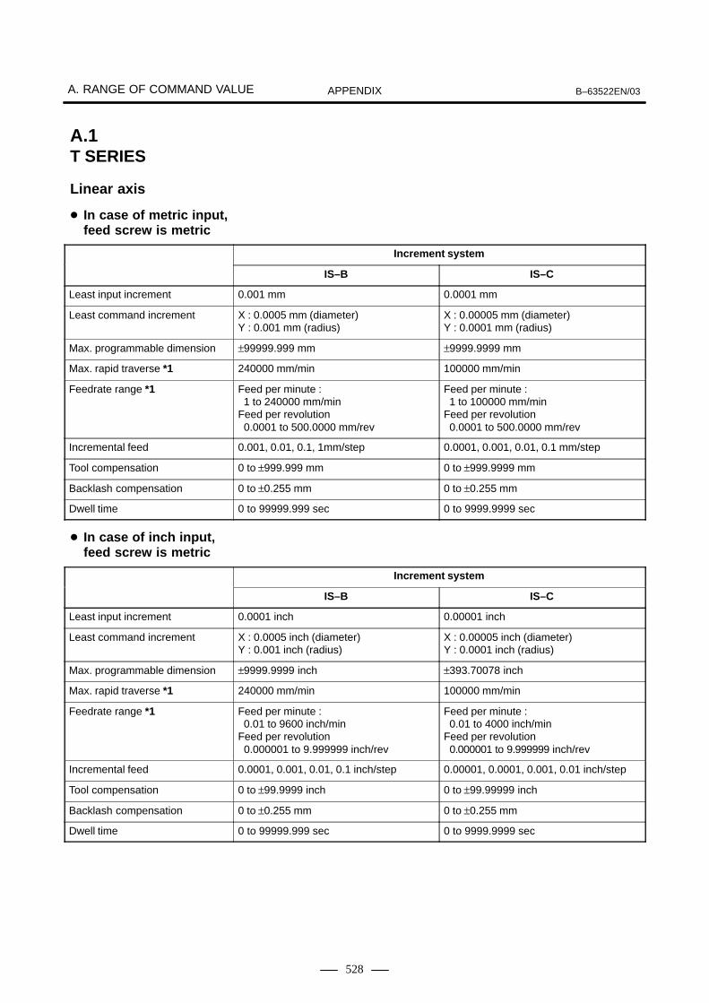
A. RANGE OF COMMAND VALUE B–63522EN/03APPENDIX
528
Increment system
IS–B IS–C
Least input increment 0.001 mm 0.0001 mm
Least command increment X : 0.0005 mm (diameter)Y : 0.001 mm (radius)
X : 0.00005 mm (diameter)Y : 0.0001 mm (radius)
Max. programmable dimension ±99999.999 mm ±9999.9999 mm
Max. rapid traverse *1 240000 mm/min 100000 mm/min
Feedrate range *1 Feed per minute : 1 to 240000 mm/minFeed per revolution 0.0001 to 500.0000 mm/rev
Feed per minute : 1 to 100000 mm/minFeed per revolution 0.0001 to 500.0000 mm/rev
Incremental feed 0.001, 0.01, 0.1, 1mm/step 0.0001, 0.001, 0.01, 0.1 mm/step
Tool compensation 0 to ±999.999 mm 0 to ±999.9999 mm
Backlash compensation 0 to ±0.255 mm 0 to ±0.255 mm
Dwell time 0 to 99999.999 sec 0 to 9999.9999 sec
Increment system
IS–B IS–C
Least input increment 0.0001 inch 0.00001 inch
Least command increment X : 0.0005 inch (diameter)Y : 0.001 inch (radius)
X : 0.00005 inch (diameter)Y : 0.0001 inch (radius)
Max. programmable dimension ±9999.9999 inch ±393.70078 inch
Max. rapid traverse *1 240000 mm/min 100000 mm/min
Feedrate range *1 Feed per minute : 0.01 to 9600 inch/minFeed per revolution 0.000001 to 9.999999 inch/rev
Feed per minute : 0.01 to 4000 inch/minFeed per revolution 0.000001 to 9.999999 inch/rev
Incremental feed 0.0001, 0.001, 0.01, 0.1 inch/step 0.00001, 0.0001, 0.001, 0.01 inch/step
Tool compensation 0 to ±99.9999 inch 0 to ±99.99999 inch
Backlash compensation 0 to ±0.255 mm 0 to ±0.255 mm
Dwell time 0 to 99999.999 sec 0 to 9999.9999 sec
A.1T SERIES
Linear axis
� In case of metric input,feed screw is metric
� In case of inch input,feed screw is metric

B–63522EN/03 A. RANGE OF COMMAND VALUEAPPENDIX
529
Increment system
IS–B IS–C
Least input increment 0.0001 inch 0.00001 inch
Least command increment X : 0.00005 inch (diameter)Y : 0.0001 inch (radius)
X : 0.000005 inch (diameter)Y : 0.00001 inch (radius)
Max. programmable dimension ±9999.9999 inch ±999.99999 inch
Max. rapid traverse *1 9600 inch/min 4000 inch/min
Feedrate range *1 Feed per minute : 0.01 to 9600 inch/minFeed per revolution 0.000001 to 9.999999 inch/rev
Feed per minute : 0.01 to 4000 inch/minFeed per revolution 0.000001 to 9.999999 inch/rev
Incremental feed 0.0001, 0.001, 0.01, 0.1 inch/step 0.00001, 0.0001, 0.001, 0.01 inch/step
Tool compensation 0 to ±99.9999 inch 0 to ±99.9999 inch
Backlash compensation 0 to ±0.0255 inch 0 to ±0.0255 inch
Dwell time 0 to 99999.999 sec 0 to 9999.9999 sec
Increment system
IS–B IS–C
Least input increment 0.001 mm 0.0001 mm
Least command increment X : 0.00005 inch (diameter)Y : 0.0001 inch (radius)
X : 0.000005 inch (diameter)Y : 0.00001 inch (radius)
Max. programmable dimension ±99999.999 mm ±9999.9999 mm
Max. rapid traverse *1 9600 inch/min 960 inch/min
Feedrate range *1 Feed per minute : 1 to 240000 mm/minFeed per revolution 0.0001 to 500.0000 mm/rev
Feed per minute : 1 to 100000 mm/minFeed per revolution 0.0001 to 500.0000 mm/rev
Incremental feed 0.001, 0.01, 0.1, 1mm/step 0.0001, 0.001, 0.01, 0.1 mm/step
Tool compensation 0 to ±999.999 mm 0 to ±999.9999 mm
Backlash compensation 0 to ±0.0255 inch 0 to ±0.0255 inch
Dwell time 0 to 99999.999 sec 0 to 9999.9999 sec
� In case of inch input,feed screw is inch
� In case of metric input,feed screw is inch

A. RANGE OF COMMAND VALUE B–63522EN/03APPENDIX
530
Increment system
IS–B IS–C
Least input increment 0.001 deg 0.0001 deg
Least command increment 0.001 deg 0.0001 deg
Max. programmable dimension ±99999.999 deg ±9999.9999 deg
Max. rapid traverse *1 240000 deg/min 100000 deg/min
Feedrate range *1 1 to 240000 deg/min 1 to 100000 deg/min
Incremental feed 0.001, 0.01, 0.1, 1deg/step 0.0001, 0.001, 0.01, 0.1 deg/step
Backlash compensation 0 to ±0.255 deg 0 to ±0.255 deg
NOTE*1 The feedrate range shown above are limitations depending
on CNC interpolation capacity.As a whole system, limitations depending on servo systemmust also be considered.
Rotation axis

B–63522EN/03 A. RANGE OF COMMAND VALUEAPPENDIX
531
Increment system
IS–A IS–B IS–C
Least input increment 0.01 mm 0.001 mm 0.0001 mm
Least command increment 0.01 mm 0.001 mm 0.0001 mm
Max. programmable dimension ±999999.99 mm ±99999.999 mm ±9999.9999 mm
Max. rapid traverse *1 240000 mm/min 240000 mm/min 100000 mm/min
Feedrate range *1 1 to 240000 mm/min 1 to 240000 mm/min 1 to 100000 mm/min
Incremental feed 0.01, 0.1, 1, 10 mm/step
0.001, 0.01, 0.1, 1 mm/step
0.0001, 0.001, 0.01, 0.1 mm/step
Tool compensation 0 to ±999.99 mm 0 to ±999.999 mm 0 to ±999.9999 mm
Dwell time 0 to 99999.999 sec 0 to 99999.999 sec 0 to 9999.9999 sec
Increment system
IS–A IS–B IS–C
Least input increment 0.001 inch 0.0001 inch 0.00001 inch
Least command increment 0.01 inch 0.001 inch 0.0001 inch
Max. programmable dimension ±99999.999 inch ±9999.9999 inch ±393.70078 inch
Max. rapid traverse *1 240000 mm/min 240000 mm/min 100000 mm/min
Feedrate range *1 0.01 to 9600 inch/min 0.01 to 9600 inch/min 0.01 to 4000 inch/min
Incremental feed 0.001, 0.01, 0.1, 1 inch/step
0.0001, 0.001, 0.01, 0.1 inch/step
0.00001, 0.0001, 0.001,0.01 inch/step
Tool compensation 0 to ±99.999 inch 0 to ±99.9999 inch 0 to ±99.99999 inch
Dwell time 0 to 99999.999 sec 0 to 99999.999 sec 0 to 9999.9999 sec
A.2M SERIES
Linear axis
� In case of metric input,feed screw is metric
� In case of inch input,feed screw is metric

A. RANGE OF COMMAND VALUE B–63522EN/03APPENDIX
532
Increment system
IS–A IS–B IS–C
Least input increment 0.001 inch 0.0001 inch 0.00001 inch
Least command increment 0.001 inch 0.0001 inch 0.00001 inch
Max. programmable dimension ±99999.999 inch ±9999.9999 inch ±999.99999 inch
Max. rapid traverse *1 9600 inch/min 9600 inch/min 4000 inch/min
Feedrate range *1 0.01 to 9600 inch/min 0.01 to 9600 inch/min 0.01 to 4000 inch/min
Incremental feed 0.001, 0.01, 0.1, 1 inch/step
0.0001, 0.001, 0.01, 0.1 inch/step
0.00001, 0.0001, 0.001,0.01 inch/step
Tool compensation 0 to ±99.999 inch 0 to ±99.9999 inch 0 to ±99.9999 inch
Dwell time 0 to 99999.999 sec 0 to 99999.999 sec 0 to 9999.9999 sec
Increment system
IS–A IS–B IS–C
Least input increment 0.01 mm 0.001 mm 0.0001 mm
Least command increment 0.001 inch 0.0001 inch 0.00001 inch
Max. programmable dimension ±999999.99 mm ±99999.999 mm ±9999.9999 mm
Max. rapid traverse *1 9600 inch/min 9600 inch/min 4000 inch/min
Feedrate range *1 1 to 240000 mm/min 1 to 240000 mm/min 1 to 100000 mm/min
Incremental feed 0.01, 0.1, 1, 10 mm/step 0.001, 0.01, 0.1, 1mm/step 0.0001, 0.001, 0.01, 0.1 mm/step
Tool compensation 0 to ±999.99 mm 0 to ±999.999 mm 0 to ±999.9999 mm
Dwell time 0 to 99999.999 sec 0 to 99999.999 sec 0 to 9999.9999 sec
� In case of inch input,feed screw is inch
� In case of metric input,feed screw is inch
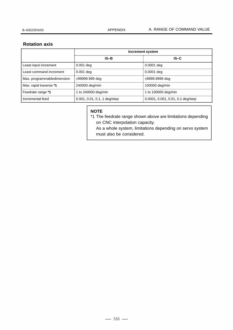
B–63522EN/03 A. RANGE OF COMMAND VALUEAPPENDIX
533
Increment system
IS–B IS–C
Least input increment 0.001 deg 0.0001 deg
Least command increment 0.001 deg 0.0001 deg
Max. programmabledimension ±99999.999 deg ±9999.9999 deg
Max. rapid traverse *1 240000 deg/min 100000 deg/min
Feedrate range *1 1 to 240000 deg/min 1 to 100000 deg/min
Incremental feed 0.001, 0.01, 0.1, 1 deg/step 0.0001, 0.001, 0.01, 0.1 deg/step
NOTE*1 The feedrate range shown above are limitations depending
on CNC interpolation capacity.As a whole system, limitations depending on servo systemmust also be considered.
Rotation axis

B. FUNCTIONS AND TAPE FORMAT LIST B–63522EN/03APPENDIX
534
B FUNCTIONS AND TAPE FORMAT LIST

B. FUNCTIONS AND TAPE FORMAT LISTB–63522EN/03 APPENDIX
535
Some functions cannot be added as options depending on the model.In the tables below, PI :presents a combination of arbitrary axisaddresses using X and Z.x = 1st basic axis (X usually) z = 2nd basic axis (Z usually)
Functions Illustration Tape format
G00 _ ;
G01 _ F_;
(x, z)
G03(x, z)
G02
G03X_ Y_
R_
I_ J_F_ ;
G04X_ ;
Start point
Start point
Positioning (G00)
Linear interpolation (G01)
Circular interpolation (G02, G03)
Dwell (G04)
Change of offset value byprogram(G10)
P_
IR
K
G02
Start point
Start point
R
K
I
Tool geometry offset value G10 P_ X(U)_ Y(V)_ Z(W)_ R(C)_
Q_ ; P=1000+Geometry offset numberTool wear offset value G10 P_ X(U)_ Y(V)_ Z(W)_ R(C)_
Q_ ; P=Wear offset number
(1/5)
IP
IP
IP
IP
G17
G02
G03X_ Z_
R_
I_ K_F_ ;G18
G02
G03Y_ Z_
R_
J_ K_F_ ;G19
Cylindrical interpolation (G07.1)(G107)
G07.1 IP_R_; Cylindrical interpolation mode
G07.1 IP0 ; Cylindrical interpolation modecancel
R: Radius of cylinder
Polar coordinate interpolation (G12.1, G13.1)(G112, G113)
G12.1 ; Polar coordinate interpolationmode
G13.1 ; Polar coordinate interpolationmode cancel
B.1T SERIES

B. FUNCTIONS AND TAPE FORMAT LIST B–63522EN/03APPENDIX
536
Functions Illustration Tape format
Reference position returncheck (G27)
Start position
G27 _ ;
Reference position return(G28)
2nd reference position re-turn (G30)
G28 _ ;
G30 _ ;
Reference position
Intermediate position
(G28)
2nd referenceposition (G30)
Skip function (G31)
Start position
Startposition
Skipsignal
G31 _ F_;
�Thread cutting (G32) Equal lead thread cutting
G32 _ F_;
(2/5)
IP
IP
IP
IP
IP
IP IP
IP
Inch/metric conversion(G20, G21)
Inch input : G20Metric input : G21
Spindle speed fluctuationdetection (G25, G26)
G25 ;G26 P_ Q_ R_ ;
Plane selection(G17, G18, G19)
G17 ;G18 ;G19 ;
(I, K)
(X, Z)Stored stroke check 2, 3(G22, G23)
G22X_ Z_ I_K_ ;G23 ;
G34 _ F_K_;IPVariable–lead threading
Automatic tool compensation(G36, G37)
Startposition
Measurementposition
Measurementposition arrivalsignal
Compensationvalue
G36 X xa ;G37 Z za ;

B. FUNCTIONS AND TAPE FORMAT LISTB–63522EN/03 APPENDIX
537
Functions Illustration Tape format
(3/5)
Coordinate system settingSpindle speed setting(G50)
X
Z
G50 Coordinate system setting
G50 S_ ; Maximum spindle speedsetting
Tool nose radius compensation(G40, G41, G42)
G41G42 IP_ ;
G40 : CancelÇÇÇÇÇÇÇÇÇ
ÇÇÇÇÇÇÇÇÇÇÇÇÇÇÇÇÇÇ
G41
G42G40
Polygon turning(G50.2, G51.2)(G250, G251)
Workpiece coordinatesystem preset (G50.3)
Local coordinate systemsetting (G52)
Machine coordinate systemselection (G53)
G51.2 (G251) P_Q_ ;P,Q :Rotation ratio of spindle and
rotary axisG50.2 (G250) ; Cancel
G50.3 IP 0 ;
x
yIP
Local coordinate
Workpiece coordinate
G52 IP _ ;
G53 IP _ ;
IPOffset from workpiece reference point
Workpiece coordinate system
Machine coordinate system
Workpiece coordinate systemselection (G54 to G59)
G54 :G59
IP _ ;
G65 P_L_ ;O_ ;
M99 ;
MacroCustom macro(G65, G66, G67)
One–shot callG65 P_L <argument> ;P : Program numberL : Repetition count
Modal callG66 P_L <argument> ;G67 ; Cancel
IP_ ;

B. FUNCTIONS AND TAPE FORMAT LIST B–63522EN/03APPENDIX
538
Feed per minute (G98)
Feed per revolution (G99)
Chamfering, Corner R
Functions Illustration Tape format
mm/min inch/minmm/rev inch/rev
G98 … F_ ;
G99 … F_ ;
�
�
�
C(K) �kR_ P_ ;X_ ;
C(I)�iR_ P_ ;Z_ ;
(4/5)
Mirror image for doubleturret (G68, G69)
G68 ; Mirror image for double turret onG69 ; Mirror image cancel
Canned cycle for drilling(G80 to G89)
See Chapter 13, “Functions toSimplify Programming” in Part II.
G80 ; CancelG83 X(U)_C(H)_Z(W)_R_Q_P_F_M_K_;G84 X(U)_C(H)_Z(W)_R_P_F_M_K_;G85 X(U)_C(H)_Z(W)_R_P_F_M_K_;G87 Z(W)_C(H)_X(U)_R_Q_P_F_M_K_;G88 Z(W)_C(H)_X(U)_R_P_F_M_K_;G89 Z(W)_C(H)_X(U)_R_P_F_M_K_;
Constant surface speedcontrol (G96/G97)
G96 S_ ;G97 ; Cancel
m/min or feet/min
� �����
Refer to II.13. FUNCTIONS TOSIMPLIFY PROGRAMMING
Canned cycle(G71 to G76)(G90, G92, G94)
N_ G70 P_ Q_ ;G71 U_ R_ ;G71 P_ Q_ U_ W_ F_ S_ T_ ;G72 W_ R_ ;G72 P_ Q_ U_ W_ F_ S_ T_ ;G73 U_ W_ R_ ;G73 P_ Q_ U_ W_ F_ S_ T_ ;G74 R_ ;G74 X(u)_ Z(w)_ P_ Q_ R_ F_ ;G75 R_ ;G75 X(u)_ Z(w)_ P_ Q_ R_ F_ ;G76 P_ Q_ R_ ;G76 X(u)_ Z(w)_ P_ Q_ R_ F_ ;
G90G92G94
X_ Z_ R_ F_ ;

B. FUNCTIONS AND TAPE FORMAT LISTB–63522EN/03 APPENDIX
539
Functions Illustration Tape format
(5/5)
Absolute/incremental programming(G90/G91)(With G code system B or C)
G90_ ; Absolute programmingG91_ ; Incremental programmingG90_ G91_ ;
Absolute and incremental programming
Return to initial point/R point(G98, G99)(With G code system B or C)
G98_ ;G99_ ;I point
G99
G98
R point
Z point

B. FUNCTIONS AND TAPE FORMAT LIST B–63522EN/03APPENDIX
540
Some functions cannot be added as options depending on the model.In the tables below, PI :presents a combination of arbitrary axisaddresses using X,Y,Z,A,B and C (such as X_Y_Z_A_).x = 1st basic axis (X usually) y = 2nd basic axis (Y usually) z = 3rd basic axis (Z usually)
Functions Illustration Tape format
G00 _ ;
G01 _ F_;
(x, y)
G03(x, y)
G17G02
G03X_ Y_
R_
I_ J_F_ ;
G18G02
G03X_ Z_
R_
I_ K_F_ ;
G19G02
G03Y_ Z_
R_
J_ K_F_ ;
G04X_ ;
Start point
Start point
Positioning (G00)
Linear interpolation (G01)
Circular interpolation (G02, G03)
Dwell (G04)
P_
JR
I
G02
Start point
Start point
R
I
J
IP
IP
IP
IP
(1/6)
(x, y)
(xyz)
zHelical interpolation(G02, G03)
Start point
When G03 is specified forthe XY plane
G17G02
G03X_ Y_
R_
I_ J_�_F_ ;
G18G02
G03X_ Z_
R_
I_ K_�_F_ ;
G19G02
G03Y_ Z_
R_
J_ K_�_F_ ;
�: Any address other than that ofa circular interpolation axis
Cylindrical interpolation(G07.1)
G07.1 IP_R_ ; Cylindrical interpolation modeR : Radius of cylinder
G07.1 IP 0 ; Cylindrical interpolation mode cancel
B.2M SERIES

B. FUNCTIONS AND TAPE FORMAT LISTB–63522EN/03 APPENDIX
541
Functions Illustration Tape format
(2/6)
� Tool offset memory AG10 L11 P_ R_ ;
� Tool offset memory BG10 L10 P_ R_ ; (Geometry offset value)G10 L11 P_ R_ ; (Wear offset value)
� Tool offset memory CG10 L10 P_ R_ ; (Geometry offset value/H)G10 L11 P_ R_ ; (Wear offset value/H) G10 L12 P_ R_ ; (Geometry offset value/D)G10 L13 P_ R_ ; (Wear offset value/D)
Velocity
Time
Exact stop (G09)
Change of offsetvalue by program(G10)
G09 _;IP
Advanced preview control(G08)
G08 P1 ; Advanced preview control mode on
G08 P0 ; Advanced preview control mode off
Polar coordinate input(G15, G16)
Local coordinate system
Workpiece coordinate system
G17 G16 Xp_Yp ⋅⋅⋅ ;G18 G16 Zp_Xp ⋅⋅⋅ ;G19 G16 Yp_Zp ⋅⋅⋅ ;G15 ; Cancel
Yp
Xp
Yp
Xp
Plane selection(G17, G18, G19)
G17 ;G18 ;G19 ;
Inch/metric conversion (G20, G21)
Reference position return check (G27)
Inch input
Metric input
G20 ;
G21 ;
G27 _ ;
Start point
IPIP
(XYZ)
(IJK)
Stored stroke check(G22, G23)
G22 X_Y_Z_I_J_K_ ;
G23 ; Cancel
G01G02G03

B. FUNCTIONS AND TAPE FORMAT LIST B–63522EN/03APPENDIX
542
Functions Illustration Tape format
(3/6)
Reference position return(G28)
2nd, reference position re-turn (G30)
G28 _ ;
G30 _ ;
Return from reference position (G29)
G29 _ ;
Skip function (G31) G31 _ F_;
Start point
Start point
Reference position
Intermediate position
Intermediate position
Reference position
Skip signal
(G28)
2nd referenceposition (G30)
IP
IPIP
IP
IP
IP
IP
ÅÅÅÅÅÅ
ÅÅÅÅÅÅ
F
ÇÇÇÇÇÇÇÇÇ
ÇÇÇÇÇÇÇÇÇÇÇÇÇÇÇÇÇÇ
G41
G42G40
Threading (G33) G33 IP _ F ;F : Lead
G17G18G19
G41G42 D_ ;
D : Tool offset numberG40 : Cancel
Cutter compensation C(G40 to G42)
Normal–direction control(G40.1, G41.1, G42.1)(G150, G151, G152)
G41.1 (G151) Normal–direction control left
G42.1 (G152) Normal–direction control right
G40.1 (G150) Normal–direction control cancel
Tool length compensation A(G43, G44, G49)
G43Z_ H_ ;
G44
G43H_ ;
G44
H : Tool offset numberG49 : Cancel
Z
Offset

B. FUNCTIONS AND TAPE FORMAT LISTB–63522EN/03 APPENDIX
543
Functions Illustration Tape format
(4/6)
Tool length compensation B (G43, G44, G49)
H : Tool offset numberG49 : Cancel
G17G18G19
H_ ;G43
G44
Z_Y_X_
G17G18G19
H_ ;G43
G44
G43
G44�_H_ ;
� : Any address of a single axisH : Tool offset numberG49 : Cancel
Tool length compensation C(G43, G44, G49)
G 46
G 45
G 47
G 48 IP
IP
Increase
Decrease
2 times increase2 timesdecrease
Compensation value
G45G46G47G48
IP _ D_ ;
D : Tool offset number
Tool offset (G45 to G48)
P1’
P1 P2
P4 P3
P2’
P4’ P3’IP
G51 X_Y_Z_ P_I_J_K_ ;
P, I, J, K : Scaling magnificationX, Y, Z : Coordinates of center of
scalingG50 ; Cancel
Scaling (G50, G51)
IP
x
yIP
Programmable mirror image(G50.1, G51.1)
Mirror G51.1 IP_ ; G50.1 ; ⋅⋅⋅⋅⋅⋅ Cancel
Local coordinate system setting (G52)
Local coordinate
Workpiece coordinate
G52 IP_ ;
Machine coordinate systemselection (G53)
G53 IP_ ;

B. FUNCTIONS AND TAPE FORMAT LIST B–63522EN/03APPENDIX
544
Functions Illustration Tape format
(5/6)
IP
IP
v
tG64
v
G61t
G65 P_L_ ;O_ ;
M99 ;
Y
X(x y)
�
Workpiece coordinate system selection (G54 to G59)Additional workpiece coordi-nate system selection(G54.1)
Offset fromworkpiece origin
Workpiece coordinate system
Machine coordinate system
G54 :G59
IP _ ;
G54.1 P _ IP_ ;
G60 IP_ ;Single direction positioning(G60)
Cutting modeExact stop modeTapping mode
Automatic corner override
G64_ ; Cutting modeG61_ ; Exact stop modeG63_ ; Tapping mode
G62_ ; Automatic corner override
Custom macro(G65, G66, G67) Macro
One–shot callG65 P_L <argument> ;P : Program numberL : Repetition count
Continuous–state callG66 P_L <argument> ;G67 ; Cancel
Coordinate system rotation(G68, G69)
G17 X_Y_G18 Z_X_G19 Y_Z_
G68 R � ;
G69 ; Cancel
XY plane
Canned cycles (G73, G74, G80 – G89)
Refer to II.14. FUNCTIONS TOSIMPLIFY PROGRAMMING
G80 ; Cancel
G73G74G76G81 :G89
X_ Y_ Z_ P_ Q_ R_ F_ K_ ;
Absolute/incremental programming (G90/G91)
G90_ ; Absolute command
G91_ ; Incremental command
G90_ G91_ ; Combined use

B. FUNCTIONS AND TAPE FORMAT LISTB–63522EN/03 APPENDIX
545
Change of workpiece coordinate system (G92) ÇÇ
ÇÇG92 _ ;
Initial point return / R point return (G98, G99)
G99
G98Initiallevel
R level
Z point
G98_ ;
G99_ ;
Functions Illustration Tape format
IP
IP
(6/6)
mm/min inch/minmm/rev inch/rev
G98 F_ ;G99 F_ ;
G96 S_ ;G97 S_ ;
Workpiece coordinate system preset (G92.1)
G92.1 0 ;IP
Feed per minute/rotation(G94, G95)
Constant surface speed control (G96, G97)

C. LIST OF TAPE CODE B–63522EN/03APPENDIX
546
C LIST OF TAPE CODE
ISO code EIA code
RemarksCharacter 8 7 6 5 4 3 2 1 Character 8 7 6 5 4 3 2 1
RemarksCustommacro B
Character 8 7 6 5 4 3 2 1 Character 8 7 6 5 4 3 2 1Not
used Used
0 � � � 0 � � Number 0
1 � � � � � 1 � � Number 1
2 � � � � � 2 � � Number 2
3 � � � � � 3 � � � � Number 3
4 � � � � � 4 � � Number 4
5 � � � � � 5 � � � � Number 5
6 � � � � � 6 � � � � Number 6
7 � � � � � � � 7 � � � � Number 7
8 � � � � � 8 � � Number 8
9 � � � � � 9 � � � � Number 9
A � � � a � � � � Address A
B � � � b � � � � Address B
C � � � � � c � � � � � � Address C
D � � � d � � � � Address D
E � � � � � e � � � � � � Address E
F � � � � � f � � � � � � Address F
G � � � � � g � � � � � � Address G
H � � � h � � � � Address H
I � � � � � i � � � � � � Address I
J � � � � � j � � � � Address J
K � � � � � k � � � � Address K
L � � � � � l � � � � Address L
M � � � � � m � � � � Address M
N � � � � � n � � � � Address N
O � � � � � � � o � � � � Address O
P � � � p � � � � � � Address P
Q � � � � � q � � � � Address Q
R � � � � � r � � � � Address R
S � � � � � s � � � � Address S
T � � � � � t � � � � Address T
U � � � � � u � � � � Address U
V � � � � � v � � � � Address V
W � � � � � � � w � � � � Address W
X � � � � � x � � � � � � Address X
Y � � � � � y � � � � Address Y

B–63522EN/03 C. LIST OF TAPE CODEAPPENDIX
547
ISO code EIA code
RemarksCharacter 8 7 6 5 4 3 2 1 Character 8 7 6 5 4 3 2 1
RemarksCustommacro B
Character 8 7 6 5 4 3 2 1 Character 8 7 6 5 4 3 2 1Not
used Used
Z � � � � � z � � � � Address Z
DEL � � � � � � � � � Del � � � � � � � �
Delete (deleting amispunch)
� �
NUL � Blank �
No. punch.With EIAcode, thiscode cannotbe used in asignificant informationsection.
� �
BS � � � BS � � � � Backspace � �
HT � � � Tab � � � � � � Tabulator � �
LF or NL � � � CR or EOB � � End of block
CR � � � � � ___ �
Carriage return
� �
SP � � � SP � � Space � �
% � � � � � ER � � � �
Absolute rewind stop
( � � � (2–4–5) � � � �
Control out(start of com-ment)
) � � � � � (2–4–7) � � � �
Control in(end of comment)
+ � � � � � + � � � � Plus sign �
– � � � � � – � � Minus sign
: � � � � � ___ �
Colon (address O)
/ � � � � � � � / � � � �
Optionalblock skip
. � � � � � . � � � � � �
Period (decimalpoint)
# � � � � �
Parameter(No. 6012)
� Sharp
$ � � � ___ � Dollar sign � �
& � � � � � & � � � � Ampersand � �
’ � � � � � ___ � Apostrophe � �
* � � � � �
Parameter(No. 6010)
� Asterisk �
, � � � � � , � � � � � � Comma
; � � � � � � � ___ � Semicolon � �
< � � � � � �
Left anglebracket
� �

C. LIST OF TAPE CODE B–63522EN/03APPENDIX
548
ISO code EIA code
RemarksCharacter 8 7 6 5 4 3 2 1 Character 8 7 6 5 4 3 2 1
RemarksCustommacro B
Character 8 7 6 5 4 3 2 1 Character 8 7 6 5 4 3 2 1Not
used Used
= � � � � � � �
Parameter (No. 6011)
� Equal sign �
> � � � � � � � ___ �
Right anglebracket
� �
? � � � � � � � ___ �
Questionmark
� �
@ � � � ___ �
Commercialat mark
� �
” � � ___ �
Quotationmark
� �
[ � � � � � � �
Parameter(No. 6013)
�
Left squarebracket
�
] � � � � � � �
Parameter(No. 6014)
�
Right squarebracket
�
NOTE1 The symbols in the Remarks column have the following meanings:
Blank: Registered in memory as significant information. Any invalid use of these codes in information other than a comment will cause an alarm.
� : Not registered in memory (ignored)� : Registered in memory but ignored during the execution of a program� : Registered in memory. The use of these codes in information other than
a comment will cause an alarm.� : Not registered in memory when used in information other than a comment.
Registered in memory when used in a comment.2 Any code other than those listed in the table is always ignored, provided its parity
is valid.� Any code having an invalid parity will cause a TH alarm. Within a comment,
however, such a code is ignored and will not cause a TH alarm. With EIA code, the code with all eight holes punched has special meaning. It is
ignored and does not cause any parity alarm.

D. EXTERNAL DIMENSIONS OF EACH UNITB–63522EN/03 APPENDIX
549
D EXTERNAL DIMENSIONS OF EACH UNIT
(Outline Drawings of the i Series CNC with a LCD–mounted Type Panel)
Outline drawing title Specification drawing number Figure
Series16i/18i/21i/20i
7.2″ STNmonochrome
16i A02B–0281–B500,B502,B503,B504 A02B–0281–H124 Fig.U116i/18i/21i/20icontrol unit
monochromeLCD panel 18i A02B–0283–B500,B502,B503,B504 A02B–0281–H124control unit LCD panel
18i–MB5 A02B–0297–B500,B502,B503,B504 A02B–0281–H124
21i A02B–0285–B500,B502,B503,B504 A02B–0281–H124
8.4″ TFT color LCD
16i A02B–0281–B500,B502,B503,B504 A02B–0281–H123 Fig.U2color LCDpanel 18i A02B–0283–B500,B502,B503,B504 A02B–0281–H123panel
18i–MB5 A02B–0297–B500,B502,B503,B504 A02B–0281–H123
21i A02B–0285–B500,B502,B503,B504 A02B–0281–H123
20i A02B–0287–B500,B502 A02B–0281–H123
9.5″ STNmonochrome
16i A02B–0281–B500,B502,B503,B504 A02B–0281–H122 Fig.U3monochromeLCD panel 18i A02B–0283–B500,B502,B503,B504 A02B–0281–H122LCD panel
18i–MB5 A02B–0297–B500,B502,B503,B504 A02B–0281–H122
21i A02B–0285–B500,B502,B503,B504 A02B–0281–H122
10.4″ TFTcolor LCD
16 A02B–0281–B500,B502,B503,B504 A02B–0281–H120,H121 Fig.U4color LCDpanel 18i A02B–0283–B500,B502,B503,B504 A02B–0281–H120,H121panel
18i–MB5 A02B–0297–B500,B502,B503,B504 A02B–0281–H120,H121
21i A02B–0285–B500,B502,B503,B504 A02B–0281–H120,H121
(Outline Drawings of the i Series CNC with a Stand–alone Type Unit)
Series 16i and Series 160i control units A02B–0281–B801, B803 Fig. U6
Series 18i and Series 180i control units A02B–0283–B801, B803
Series 18i–MB5 and Series 180i–MB5 control units A02B–0297–B801, B803
Series 21i and Series 210i control units A02B–0285–B801, B803
10.4″/9.5″ LCD unit A02B–0281–C071, C081, C061, C066 Fig. U7
7.2″ LCD/MDI unit (Unit applied to display link) A02B–0166–C261#TR, R, TS, S Fig. U8
7.2″ monochrome LCD unit (Unit applied to display link) A02B–0166–C251 Fig. U9
MDI unit (for 7.2″ LCD) (Unit applied to display link) A02B–0166–C210#TR, TS, R, S Fig. U10
Detachable 7.2″ LCD/MDI unit (Unit applied to display link) A02B–0166–C271#TR, TS, R, S Fig. U11

D. EXTERNAL DIMENSIONS OF EACH UNIT B–63522EN/03APPENDIX
550
(Outline Drawings of PANEL i (CNC display unit with PC functions))
PANEL i (CNCdisplay unit withPC functions)
10.4” TFT colorLCD panel
A08B–0082–B001 to –B004A08B–0082–B031 to –B038A08B–0193–B031 to –B038
Fig.U12(a)
12.1” TFT colorLCD panel
A08B–0082–B011 to –B014A08B–0082–B041 to –B048A08B–0193–B041 to –B048
Fig.U12(b)
15.0” TFT colorLCD panel
A08B–0082–B021 and –B023A08B–0082–B051 to –B057A08B–0193–B051 to –B057
Fig.U12(c)
(Outline drawings of other units)
Stand–alone typesmall MDI unit
For 7.2”/8.4” LCDunit
A02B–0281–C120#TBR, MBR, TBS, MBS, TBE, MBE Fig.U13
Stand–alone typestandard MDI unit
For 7.2”/8.4” LCDunit
A02B–0281–C121#TBR, MBR, TBS, MBS, TBE, MBE Fig.U14
Stand–alone typestandard MDI unit(horizontal type)
For 9.5”/10.4” LCDunit
A02B–0281–C125#TBR, MBR, TBS, MBS, TFBR, TFBS, TBE, MBE Fig.U15
Stand–alone typestandard MDI unit(vertical type)
For 9.5”/10.4” LCDunit
A02B–0281–C126#TBR, MBR, TBS, MBS, TFBR, TFBS, TBE, MBE Fig.U16
FA full keyboard For 10.4” LCD unit A02B–0236–C131#EC, JC Fig.U17(a)
FA full keyboard For 12.1” LCD unit A02B–0236–C132#EC, JC Fig.U17(b)
FA full keyboard For 15.0” LCD unit A08B–0082–C150#EC, JC Fig.U17(c)
Full keyboard (for debugging purposes) A86L–0001–0210, 0211 Fig.U18
Mouse (for debugging purposes) A86L–0001–0212 Fig.U19
Floppy disk unit (for debugging purposes) A02B–0207–C008 Fig.U20
HSSB interface board type 2 (1CH) onthe personal computer side (ISA)
A20B–8001–0583 Fig.U21(a)
HSSB interface board type 2 (2CH) onthe personal computer side (ISA)
A20B–8001–0582
HSSB interface board type 2 (1CH) onthe personal computer side (PCI)
A20B–8001–0961 Fig.U21(b)
HSSB interface board type 2 (2CH) onthe personal computer side (PCI)
A20B–8001–0960
Position coder 4000min–1 A86L–0027–0001#102 Fig.U22(a)
6000min–1 A86L–0027–0001#002
α position coder 10000mi–1 A860–0309–T302 Fig.U22(b)
Manual pulse generator A860–0202–T001 Fig.U23
Pendant manual pulse generator A860–0202–T004 to T015 Fig.U24
Separate detector interface unit A02B–0236–C205, C204 Fig.U25
Battery case for separate detector interface unit (ABS)
A06B–6050–K060 Fig.U26
Tap unit for DNC1 A13B–0156–C100 Fig.U27
Terminating resistance unit for DNC1 A13B–0156–C200 Fig.U28

D. EXTERNAL DIMENSIONS OF EACH UNITB–63522EN/03 APPENDIX
551
CNC battery unit for external installation A02B–0236–C281 Fig.U29
Punch panel (narrow type)
1m A02B–0236–C191 Fig.U30(narrow type)
2m A02B–0236–C192
5m A02B–0236–C193
Punch panel 1m A02B–0120–C191 Fig.U31
2m A02B–0120–C192
5m A02B–0120–C193
Distribution I/O small machine operator’s panel
A02B–0236–C141#TBR, MBR, TBS, MBS Fig.U32
Distribution I/O standard machine operator’s panel
A02B–0236–C140#TBR, MBR, TBS, MBS Fig.U33
61–key MDI unit (vertical type)
For 9.5”/10.4” LCD unit
A02B–0261–C161#MCR, MCS Fig.U34(vertical type) unit A02B–0261–C163#MCR, MCS
61–key MDI unit (horizontal type)
For 9.5”/10.4” LCD unit
A02B–0261–C162#MCR, MCS Fig.U35(horizontal type) unit A02B–0261–C164#MCR, MCS
61–key MDI unit (horizontal type)
For 12.1” LCD unit A02B–0261–C165#MCR, MCS Fig.U36
61–key MDI unit (horizontal type)
For 12.1” LCD unit A02B–0261–C166#MCR, MCS Fig.U37
Blank panel Supplied with the 61–key MDI unit (A02B–0261–C165, C166). Fig.U38
Distribution I/O machine operator’s panel (290mm wide)
A02B–0236–C150#TBR, MBR, TBS, MBS Fig.U39
Stand–alone typestandard MDI unitfor 160i/180i/210i
For 10.4”(vertical type)
A02B–0281–C327#TBR, MBR, TBS, MBS Fig.U40(a)
for 160i/180i/210iFor 10.4”(horizontarl type)
A02B–0281–C320#TBR, MBR, TBS, MBS Fig.U40(b)

D. EXTERNAL DIMENSIONS OF EACH UNIT B–63522EN/03APPENDIX
552
At the rear of the metalpanel, the area within 8mm of the outside edge isleft unpainted.Install the unit from theoutside of the cabinet.
Mounting hole diagram
With no option slot
With 2 option slots
Number ofoption slots
Depth(D) (mm)
2
3
4
110
125
170
Color : Munsell N3, semi–glossed
Fig. U1 External dimensions of 7.2″ LCD–mounted type CNC control unit

D. EXTERNAL DIMENSIONS OF EACH UNITB–63522EN/03 APPENDIX
553
At the rear of the metalpanel, the area within 8mm of the outside edge isleft unpainted.Install the unit from theoutside of the cabinet.
Mounting hole diagram
With no option slot
With 2 option slots
Number ofoption slots
Depth(D) (mm)
2
3
4
110
125
170
Color : Munsell N3, semi–glossed
Fig. U2 External dimensions of 8.4″ LCD–mounted type CNC control unit

D. EXTERNAL DIMENSIONS OF EACH UNIT B–63522EN/03APPENDIX
554
At the rear of the metalpanel, the area within 8mm of the outside edge isleft unpainted.Install the unit from theoutside of the cabinet.
Mounting hole diagram
With no option slot
With 2 option slots
Number ofoption slots
Depth(D) (mm)
2
3
4
110
125
170
Color : Munsell N3, semi–glossed
Fig. U3 External dimensions of 9.5″ LCD–mounted type CNC control unit

D. EXTERNAL DIMENSIONS OF EACH UNITB–63522EN/03 APPENDIX
555
At the rear of the metalpanel, the area within 8mm of the outside edge isleft unpainted.Install the unit from theoutside of the cabinet.
Mounting hole diagram
With no option slot
With 2 option slots
Number ofoption slots
Depth(D) (mm)
2
3
4
110
125
170
Color : Munsell N3, semi–glossed
Fig. U4 External dimensions of 10.4″ LCD–mounted type CNC control unit

D. EXTERNAL DIMENSIONS OF EACH UNIT B–63522EN/03APPENDIX
556
172 (for 3–slot type)
60 (for 1–slot type)
Weight : For 1–slot type, 0.7 kgFor 3–slot type, 1.9 kg
For both types, the stated weightdoes not include printed–circuitboards inserted in the slots.
Memory card
Slot 1
Slot 3 Slot 2
Fig. U6 Stand–alone Type i Series Control Unit

D. EXTERNAL DIMENSIONS OF EACH UNITB–63522EN/03 APPENDIX
557
4–M3
4–�4290
2805 5
220
521
05
Mounting hole layout diagram(The unit shall be fastened to the cabinet from the outside.)Painting shall be masked 8 mm from the edges of the panel sheet metalon the rear surface.
Paint color: Munsell code N3, medium gloss
Fig. U7 10.4″/9.5″ LCD Unit

D. EXTERNAL DIMENSIONS OF EACH UNIT B–63522EN/03APPENDIX
558
Groundingstud (M4)
Groundingstud (M4)
Paint color: Munsell code N3, medium gloss
The unit shall be fastened to the cabinet from the outside.
Weight: 3.9 kg
(Mou
ntin
g ho
le la
yout
dia
gram
)
Fig. U8 7.2″ LCD/MDI Unit Outline Drawing (Unit applied to display link)

D. EXTERNAL DIMENSIONS OF EACH UNITB–63522EN/03 APPENDIX
559
The unit shall be fastened to the cabinet from the outside.
Paint color: Munsell code N3, medium glossWeight: 1.6 kg
Mou
ntin
g ho
le la
yout
dia
gram
Pan
el c
ut p
atte
rn la
yout
dra
win
g
Gro
undi
ng s
tud
(M4)
Sof
t-ke
y co
nnec
tor
Fig. U9 7.2″ Monochrome LCD Unit Outline Drawing (Unit applied to display link)

D. EXTERNAL DIMENSIONS OF EACH UNIT B–63522EN/03APPENDIX
560
Grounding stud (M4) (Mounting holelayout diagram)
Grounding stud (M4)
Paint color: Munsell code N3, medium glossThe unit shall be fastened to the cabinet from the outside.
Weight: 1.3 kg
Fig. U10 Stand–alone type MDI Unit (for 7.2″ Stand–alone type LCD) (Unit applied to display link)

D. EXTERNAL DIMENSIONS OF EACH UNITB–63522EN/03 APPENDIX
561
Paint color: For case, Munsell code 5GY3.5/0.5, medium glossFor panel, Munsell code N3, medium gloss
Weight: 7 kg
Fig. U11 Detachable 7.2″ LCD/MDI Unit (Unit applied to display link)

D. EXTERNAL DIMENSIONS OF EACH UNIT B–63522EN/03APPENDIX
562
204
210
55
220
27 (From
the outside of the plate)
125(With PCI Extension Board Fitting Plate)
60(Without PCI Extension Board Fitting Plate)
Paint Masking(Mounting side of this plate is unpainted in 8mm width from the edge )
Maximum PCI card defined at Connecting 4.
(Basic Unit is mounted from outsideof the panel)
Weight: 3.3kg
Unit : mm
Upper View
Side View
Panel Cutting
Front View
290
225
2805 5
4–φ4
280
274
4–M3
(HOLE)
20
210
Fig. U12 (a) External dimensions of 10.4″ TFT color LCD of PANEL i (CNC display unit with PC functions)

D. EXTERNAL DIMENSIONS OF EACH UNITB–63522EN/03 APPENDIX
563
57��������
���������������
��������
270
280
�
125(With PCI Extension Board Fitting Plate)
60(Without PCI Extension Board Fitting Plate)
Paint Masking(Mounting side of this plate is unpainted in 8mm width from the edge )
Unit : mm
Upper View
Side View
Panel Cutting
Front View
6–�4
(Basic Unit is mounted from outsideof the panel)
Weight: 4.5kg
340
2 2530
165
324
165
165 165
6–M3
5
(HOLE)
5
5
270
264
Fig. U12 (b) External dimensions of 12.1″ TFT color LCD of PANEL i (CNC display unit with PC functions)
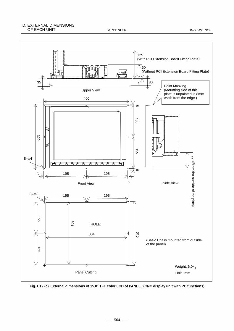
D. EXTERNAL DIMENSIONS OF EACH UNIT B–63522EN/03APPENDIX
564
��
��
��
���
���
��
�
��������
���������������
��������
125(With PCI Extension Board Fitting Plate)
60(Without PCI Extension Board Fitting Plate)
Paint Masking(Mounting side of this plate is unpainted in 8mm width from the edge )
Unit : mm
Upper View
Side ViewFront View
8–�4
(Basic Unit is mounted from outsideof the panel)
400
2 30
(HOLE)
5
35
5
Panel Cutting
384
195 195
8–M3 195 195
Weight: 6.0kg
77
��
Fig. U12 (c) External dimensions of 15.0″ TFT color LCD of PANEL i (CNC display unit with PC functions)

D. EXTERNAL DIMENSIONS OF EACH UNITB–63522EN/03 APPENDIX
565
Mounting hole diagram
At the rear of the metal panel, the area within 8 mm ofthe outside edge is left unpainted.Install the unit from the outside of the cabinet.
��� �
5
5
190
4–�4
�
11
��
69
48
30
Color : Munsell N3, semi–glossed
Fig. U13 External dimensions of stand–alone type small–size MDI unit

D. EXTERNAL DIMENSIONS OF EACH UNIT B–63522EN/03APPENDIX
566
Mounting hole diagram
At the rear of the metalpanel, the area within8 mm of the outsideedge is left unpainted.Install the unit from theoutside of the cabinet.
Color : Munsell N3, semi–glossed
Fig. U14 External dimensions of stand–alone type standard MDI unit

D. EXTERNAL DIMENSIONS OF EACH UNITB–63522EN/03 APPENDIX
567
At the rear of the metalpanel, the area within8 mm of the outsideedge is left unpainted.Install the unit from theoutside of the cabinet.
Mounting hole diagram
Color : Munsell N3, semi–glossed
Fig. U15 External dimensions of stand–alone type standard MDI unit (horizontal type)

D. EXTERNAL DIMENSIONS OF EACH UNIT B–63522EN/03APPENDIX
568
At the rear of the metalpanel, the area within8 mm of the outsideedge is left unpainted.Install the unit from theoutside of the cabinet.
Mounting hole diagram
Color : Munsell N3, semi–glossed
�
Fig. U16 External dimensions of stand–alone type standard MDI unit (vertical type)

D. EXTERNAL DIMENSIONS OF EACH UNITB–63522EN/03 APPENDIX
569
40
32
305
220
4–φ5
1550�40 250�40
290
2
20 60.6
610
5
20
5660
a
a
a
a
b
a: M5�10mm b: M5�10mm (Frame GND)
Weight : 3.5 kg(Unit :mm)
Fig. U17 (a) FA Full Keyboard 10.4″ LCD Type (Specification: A02B–0236–C131#JC,A02B–0236–C131#EC)

D. EXTERNAL DIMENSIONS OF EACH UNIT B–63522EN/03APPENDIX
570
���
�
��
���
6–φ5
1550�40 250�40
340
2
20 60.6
610
5
20
ab
a
a
a
110
54
a: M5�10mm b: M5�10mm
(Frame GND)
Weight : 3.7 kg(Unit :mm)
Fig. U17 (b) FA Full Keyboard 12.1″ LCD Type (Specification: A02B–0236–C132#JC,A02B–0236–C132#EC)

D. EXTERNAL DIMENSIONS OF EACH UNITB–63522EN/03 APPENDIX
571
��
��
���
!
���
"�
��
�
�
�
���
1550�40 250�40
2
2060.6
6–φ5
400
140
b
80
86
34
��
5 35
2–φ5Unpaint rear side(φ10)
b: M5�10mm (Frame GND)
Weight :3.9 kg(Unit :mm)
Blank Panel
Hole of ConnectorPanel27
Fig. U17 (c) FA Full Keyboard 15.0″ LCD Type (Specification: A08B–0082–C150#JC, A08B–0082–C150#EC)

D. EXTERNAL DIMENSIONS OF EACH UNIT B–63522EN/03APPENDIX
572
204
204204
210
210210
�# ���� $�%&���� �� ' ()* +%��
�# ���� $�%&���� ��' ()* +%��
�# ���� $�%&���� ���' ()* +%��
����, ����� �� ��-� ��-���� �� ������� �&���
����� -�����. �� /���- 0���� ��� �����%
*������� *��1��
HOLE
HOLE
HOLE
280
274
330
324
162
384
192
390
4–M3
6–M3
6–M3
Fig. U17 (d) Panel Cutting

D. EXTERNAL DIMENSIONS OF EACH UNITB–63522EN/03 APPENDIX
573
Full Keyboard 101 key (A86L–0001–0210) (Unit : mm)
(Unit : mm)Full Keyboard 106key (A86L–0001–0211)
Note:These units can be used only during application development and maintenance ,and this is not dust proof. .Ambient temperature during operation is 0�C–40�C.
Fig. U18 Full Keyboard 101/106key

D. EXTERNAL DIMENSIONS OF EACH UNIT B–63522EN/03APPENDIX
574
1800�190
Note:This unit can be used only during application development and maintenance ,and this is not dust proof. .Ambient temperature during operation is 0�C–40�C.
(Unit : mm)
Cap Ball
Name Plate of Unit
Fig. U19 Mouse (Specification: A86L–0001–0212)

D. EXTERNAL DIMENSIONS OF EACH UNITB–63522EN/03 APPENDIX
575
104
134
140
514
0
150
5
4–M3
64
(HOLE)
70
FDD
ACRYLICWINDOW
70
80
55
4–φ3.6
145
(Unit : mm)
J2
J1
Mounting directionWhen using the floppy disk unit attached to the machine, mount the floppy disk unit in one of the following directions:
Side View
Panel Cutting
Fornt View
Fig. U20 Floppy disk unitSpecification No.: A20B–0207–C008

D. EXTERNAL DIMENSIONS OF EACH UNIT B–63522EN/03APPENDIX
576
–0582 –0583
Weight: 0.2 kg
Fig. U21 (a) High–speed serial bus interface board type 2 (PC) (ISA bus version)Specification No.: A20B–8001–0583 (1 CH)
A20B–8001–0582 (2 CH)
09600961
Fig. U21 (b) Interface Board for Personal Computer (PCI bus version)Specification No.: A20B–8001–0960 (2 CH)
A20B–8001–0961 (1 CH)

D. EXTERNAL DIMENSIONS OF EACH UNITB–63522EN/03 APPENDIX
577
Note: Mechanical specifications of the position coder are as follows:(1) Input axis inertia
1.0 × 10⁻³ kg⋅cm⋅sec2 or less(2) Input axis starting torque
1000 g⋅cm or less(3) Allowable input axis load
Driving the timing belt with a pulley directly attached to the position coder shaft may produce an axis load greater than the allowed maximum.
(4) Weight: Approx. 1 kg (without the flange)
Radial load Thrust load
+0.05–0
+00
12–0
4 �5.4
3
�56
�68
98
2
MS3102A20–29P
2 1.15+0.14–0
20
30 3 5
31 +0.15
5
Key position
72
52
68
50–0
.009
–0.0
25
15 14.3
16
–0.0
06–0
.017
+0
–0.1
1
Operating 10 kg or less 5 kg or less
Idle 20 kg or less 10 kg or less
Fig. U22 (a) External dimensions of position coderSpecification No.: A86L–0027–0001#102 (Max. 4000 min–1)
A86L–0027–0001#002 (Max. 6000 min–1)

D. EXTERNAL DIMENSIONS OF EACH UNIT B–63522EN/03APPENDIX
578
MC connector: MS3102A–20–29P
Fig. U22 (b) α position coderSpecification No.: A860–0309–T302 (10000 min–1 maximum)

D. EXTERNAL DIMENSIONS OF EACH UNITB–63522EN/03 APPENDIX
579
3–M4On the �72 circumference
Fig. U23 External dimensions of manual pulse generatorSpecification No.: A860–0203–T001

D. EXTERNAL DIMENSIONS OF EACH UNIT B–63522EN/03APPENDIX
580
A860–0203–T010 to T015
Fig. U24 External dimensions of pendant–type manual pulse generator Specification No.: A860–0203–T010 to T015

D. EXTERNAL DIMENSIONS OF EACH UNITB–63522EN/03 APPENDIX
581
CP
11
JF10
1(JF
105)
JF10
2(JF
106)
JF10
3(JF
107)
JF10
4(JF
108)
JA4A
CO
P10
BC
OP
10A
The connector names in parentheses are foran expansion unit. The expansion unit doesnot have connectors CP11, JA4A, COP10A,and COP10B.
Fig. U25 External dimensions of separate detector interface unit

D. EXTERNAL DIMENSIONS OF EACH UNIT B–63522EN/03APPENDIX
582
103
FANUC
40
A
78 78
4–M4 counter sinking
Negative polarity indication
Positive polarity indication
Plus terminalwith 3–M3screw holes
Minus terminal with 3–M3 screw holes
4–�4.3 mounting hole
Arrow view A
Note) The battery is not included.
103
14.1
����
� ��
���
��
Fig. U26 External dimensions of ABS battery case for separate detectorSpecification No.: A06B–6050–K060
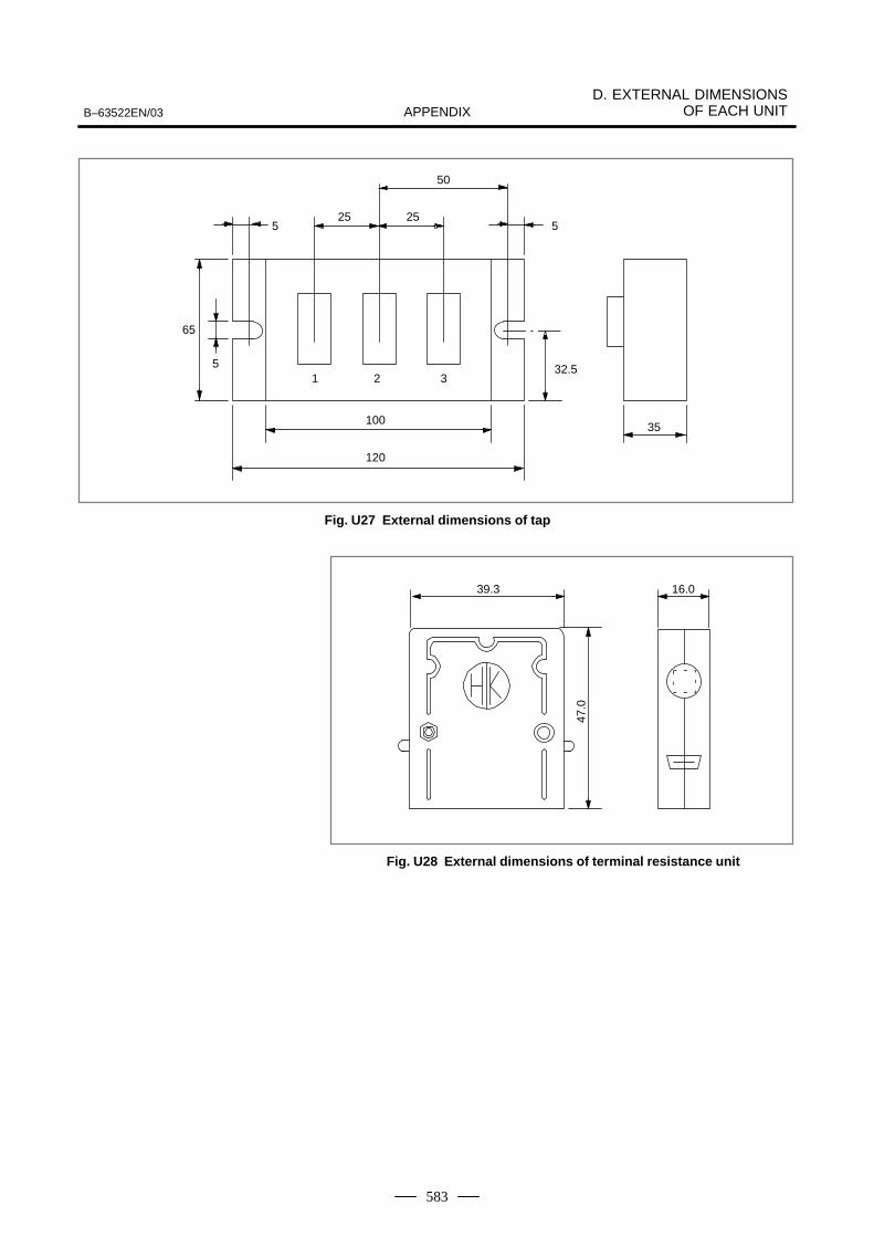
D. EXTERNAL DIMENSIONS OF EACH UNITB–63522EN/03 APPENDIX
583
ÁÁÁÁÁÁÁÁ
ÁÁÁÁÁÁÁÁ
ÁÁ
ÁÁÁÁ
ÁÁÁÁ
ÁÁ
ÁÁ
Á
ÁÁ
ÁÁÁÁ
ÁÁ
65
5
5
25 25
50
5
32.5
35100
120
1 2 3
Fig. U27 External dimensions of tap
ÔÔÔÔÔÔ
16.039.347
.0
Fig. U28 External dimensions of terminal resistance unit

D. EXTERNAL DIMENSIONS OF EACH UNIT B–63522EN/03APPENDIX
584
103
5
13.5 47
115
70
81 93
145
The battery unit is fitted with a 14–m battery cable.
Mounting hole (countersink)
Mounting panel hole drilling
M4 tap × 4
Main unitCover
Fig. U29 External dimensions of external CNC battery unit

D. EXTERNAL DIMENSIONS OF EACH UNITB–63522EN/03 APPENDIX
585
Mounting hole diagram
At the rear of the metalpanel, the area within 8mm of the outside edge isleft unpainted.
Fig. U30 External dimensions of punch panel (narrow type)

D. EXTERNAL DIMENSIONS OF EACH UNIT B–63522EN/03APPENDIX
586
Painting shall be masked 8 mm from the edges of the panelsheet metal on the rear surface.
The following is the panel cut layout drawing of this punch panel.
20
2–M3
100
115
Fig. U31 Punch Panel (Narrow Type)Specification No.: A02B–0120–C191 (cable length 1 m)
A02B–0120–C192 (cable length 2 m)A02B–0120–C193 (cable length 5 m)

D. EXTERNAL DIMENSIONS OF EACH UNITB–63522EN/03 APPENDIX
587
Pan
el c
uttin
g dr
awin
g
Thi
s m
etal
pla
te c
an b
e re
mov
ed.
Pro
tect
ion
grou
ndin
g st
ud (
M4,
bac
k si
de)
Color : Munsell N3, semi–glossedWeight: 2.3kg
At the rear of the metalpanel, the area within 8mm of the outside edge isleft unpainted.Install the unit from theoutside of the cabinet.
Fig. U32 Distribution I/O small machine operator’s panel

D. EXTERNAL DIMENSIONS OF EACH UNIT B–63522EN/03APPENDIX
588
Pan
el c
uttin
g dr
awin
g
Thi
s m
etal
pla
te c
an b
e re
mov
ed.
Pro
tect
ion
grou
ndin
g st
ud (
M4,
bac
k si
de)
Color : Munsell N3, semi–glossedWeight: 2.8kg
At the rear of the metalpanel, the area within 8mm of the outside edge isleft unpainted.Install the unit from theoutside of the cabinet.
Fig. U33 Distribution I/O standard machine operator’s panel

D. EXTERNAL DIMENSIONS OF EACH UNITB–63522EN/03 APPENDIX
589
The
bac
k of
the
met
al p
late
is m
aske
d, 8
mm
wid
e al
ong
the
outs
ide
edge
, to
prev
ent p
aint
ing.
Mou
ntin
g ho
le d
iagr
am
Up
Protective grounding stud (M4)
Weight: 2.0kg
Fig. U34 61–key MDI unit (vertical type)
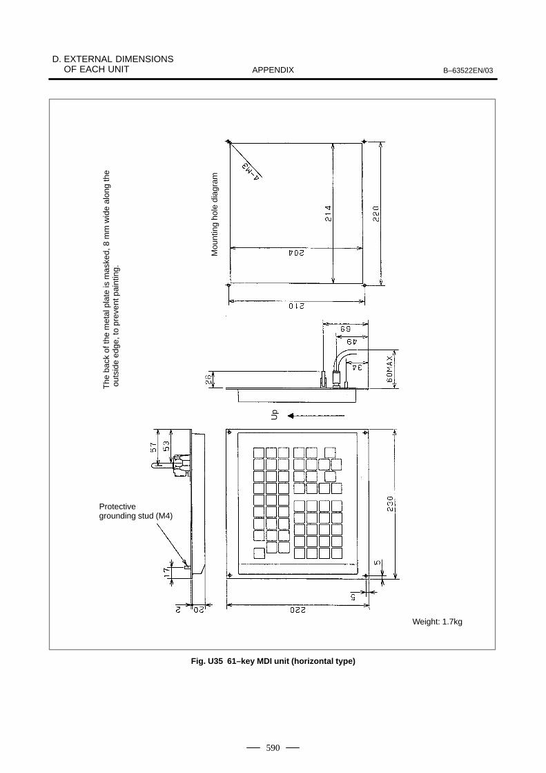
D. EXTERNAL DIMENSIONS OF EACH UNIT B–63522EN/03APPENDIX
590
Mou
ntin
g ho
le d
iagr
am
Up
Protective grounding stud (M4)
Weight: 1.7kg
The
bac
k of
the
met
al p
late
is m
aske
d, 8
mm
wid
e al
ong
the
outs
ide
edge
, to
prev
ent p
aint
ing.
Fig. U35 61–key MDI unit (horizontal type)

D. EXTERNAL DIMENSIONS OF EACH UNITB–63522EN/03 APPENDIX
591
Up
Protective grounding stud (M4)
Weight: 2.0kg
The
bac
k of
the
met
al p
late
is m
aske
d, 8
mm
wid
e al
ong
the
outs
ide
edge
, to
prev
ent p
aint
ing.
Con
nect
or p
anel
Bla
nk p
anel
A
n ou
tline
dra
win
g of
the
blan
k pa
nel i
s gi
ven
in F
ig. U
38.
Fig. U36 61–key MDI unit (vertical type)

D. EXTERNAL DIMENSIONS OF EACH UNIT B–63522EN/03APPENDIX
592
Up
Protective grounding stud (M4)
Weight: 2.0kg
The
bac
k of
the
met
al p
late
is m
aske
d, 8
mm
wid
e al
ong
the
outs
ide
edge
, to
prev
ent p
aint
ing.
Con
nect
or p
anel
Bla
nk p
anel
A
n ou
tline
dra
win
g of
the
blan
k pa
nel i
s gi
ven
in F
ig. U
38.
Fig. U37 61–key MDI unit (horizontal type)

D. EXTERNAL DIMENSIONS OF EACH UNITB–63522EN/03 APPENDIX
593
The
hat
ched
por
tion
is a
n op
enin
g of
the
conn
ecto
r pa
nel.
The
bac
k of
the
blan
k pa
nel i
s m
aske
d,w
ith a
dia
met
er o
f 10.
Fig. U38 Blank panel

D. EXTERNAL DIMENSIONS OF EACH UNIT B–63522EN/03APPENDIX
594
Mou
ntin
g ho
le d
iagr
am
Weight: 2.0kg
Not
e) O
n th
e ba
ck o
f the
pla
te a
ttach
ed to
the
pane
l, co
atin
g is
mas
ked
ar
ound
the
perip
hera
l are
a w
ith a
wid
th o
f 8 m
m.
In
stal
l the
uni
t fro
m th
e ou
tsid
e of
the
cabi
net.
Thi
s pl
ate
is r
emov
able
.
Col
or: M
unse
ll N
3, s
emi–
glos
sed
Pro
tect
ive
grou
ndin
g st
ud (
M4)
(B
ack
side
)
Fig. U39 Distributed I/O machine operator’s panel (290 mm wide)
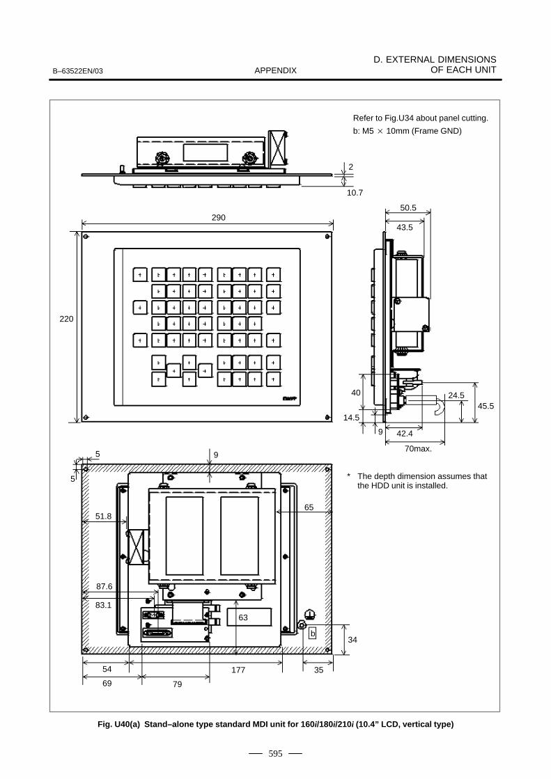
D. EXTERNAL DIMENSIONS OF EACH UNITB–63522EN/03 APPENDIX
595
Refer to Fig.U34 about panel cutting.
b: M5 � 10mm (Frame GND)
2
10.7
290
220
50.5
43.5
40
14.5
9 42.4
70max.
24.545.5
5
5
9
51.8
87.6
83.1
54
69 79
177 35
34b
63
65
* The depth dimension assumes thatthe HDD unit is installed.
Fig. U40(a) Stand–alone type standard MDI unit for 160i/180i/210i (10.4” LCD, vertical type)

D. EXTERNAL DIMENSIONS OF EACH UNIT B–63522EN/03APPENDIX
596
Refer to Fig.U35 about panel cutting.
b: M5 � 10mm (Frame GND)
2
10.7
230
220
4–�4
50.5
43.5
40
14.5
9 42.4
24.545.5
70max.95
5
21.8
57.6
53.1
24
39 79
17718
16
35
63
b
* The depth dimension assumes thatthe HDD unit is installed.
Fig. U40(b) Stand–alone type standard MDI unit for 160i/180i/210i (10.4” LCD, horizontal type)
IndexB–63522EN/03
i–1
[Symbols]αi Servo Information Screen, 394
αi Spindle Information Screen, 395
[Numbers]1–block Plural M Command, 135
160i/180i/210i, 448
160is/180is/210is, 450
2nd, 3rd and 4th Reference Position Return (G30), 97
3–dimensional Circular Interpolation (G02.4 andG03.4), 75
7.2″/8.4″ LCD–mounted Type CNC Control Unit, 345
9.5″/10.4″ LCD–mounted Type CNC Control Unit,346
[A]Abnormal Load Detection, 437
Absolute and Incremental Programming (G90, G91),115
Acceleration/Deceleration and Automatic Phase Syn-chronization, 309
Acceleration/Deceleration Before Interpolation byPre-reading Multiple Blocks, 280
Acceleration/Deceleration Type, 308
Accuracy Compensation Function, 225
Activation of Automatic Operation, 333
Actual Spindle Speed Output (T series), 121
Addition of Tool Pairs for Tool Life Management<512 Pairs (M series) / 128 Pairs (T series)>, 132
Additional Optional Block Skip, 144
Additional Workpiece Coordinate Systems (M series),110
Adifference Among Pitch Error Compensation, In-clination Compensation, and Straightness Com-pensation, 231
Advanced Preview Control (G08), 275
AI Advanced Preview Control (for the 21i–M Only)(G05.1) (M series), 285
AI Contour Control (G05.1) (M series), 282
AI High–precision Contour Control AI Nano High–precision Contour Control, 283
AI Nano Contour Control (G05.1), 285
Alarm Signal, 440
All Axes Interlock, 436
All–axes Machine Lock, 342
Angular Axis Control, 299
Applicable Machines, 461, 468
Arbitrary Angular Axis Control, 299
Automatic Acceleration/Deceleration, 85
Automatic Coordinate System Setting, 105
Automatic Corner Deceleration, 273
Automatic Corner Override (G62) (M series), 91
Automatic Operation, 330
Automatic Operation Signal, 440
Automatic Operation Start Signal, 440
Automatic Operation Stop, 334
Automatic Reference Position Return (G28, G29) (Mseries), 96
Automatic Tool Offset (G37, G36) (T series), 246
Automatic Velocity Control Function, 281
Auxiliary Function Lock, 342
Axes Control, 289
Axis Control by PMC, 37
Axis Control with PMC, 298
Axis Move Direction Signal, 441
Axis Names, 38
Axis Recomposition (T series), 321
[B]B–axis Control (T series), 299
Background Drawing (M series), 367
Background Editing, 397
Backlash Compensation, 233
Backlash Compensation Specific to Rapid Traverseand Cutting Feed, 233
Balance Cut (G68, G69) (T series), 320
Basic Addresses and Command Value Range, 142
Bell–shaped Acceleration/Deceleration After CuttingFeed Interpolation, 88
Bi–directional Pitch Error Compensation, 226
Block Start Interlock, 436
Buffer Register, 333
Butt–type Reference Position Setting, 99
[C]C Language Executer Function, 264
Canceling Alarm 101, 523
Index B–63522EN/03
i–2
Canned Cycles (G73, G74, G76, G80–G89, G98, G99)(M series), 146
Canned Cycles for Cylindrical Grinding (T series),183
Canned Cycles for Drilling (G80–G89) (T series), 174
Canned Cycles for Turning (T series), 159
Chamfering and Corner R ( T series), 175
Changing of Tool Offset Amount (Programmable DataInput) (G10), 213
Chopping Function (G80, G81.1) (M series), 301
Chuck/Tail Stock Barrier (T series), 433
Circular Interpolation (G02, G03), 54
Circular Threading (G35, G36) (T series), 79
Clearing All Memory Data, 523
Clearing the Screen, 379
Clock Function, 357
Color Setting Screen, 381
Constant Surface Speed Control, 121
Constant Surface Speed Control Signal, 441
Continuous Feed Plane Grinding Cycle (G78), 190
Continuous High–speed Skip Function (G31, P90) (Mseries), 244
Continuous Thread Cutting (T series), 79
Contrast Adjustment Screen, 382
Control Axis Detach, 290
Control–in/Control–out, 144
Controlled Axes, 34
Conversational Automatic Programming Function forLathes, 460
Conversational Automatic Programming Function forMachining Centers, 482
Conversational Programming of Figures (Only at1–path Control), 399
Coordinate System Conversion, 236
Coordinate System Rotation (G68, G69) – (M series)(G68.1, G69.1) – (T series), 237
Coordinate Systems, 101
Coordinate Value and Dimension, 114
Copying a Program Between Two Paths, 323
Corner Circular Interpolation Function (G39) (M se-ries), 208
Corner Circular Interpolation Function (G39) (T se-ries), 203
Count Input of Tool Offset Values (T series), 253
Counter Input in a Workpiece Coordinate System, 107
Cs Contour Control, 37, 125
Custom Macro, 254, 255
Cutter Compensation (M series), 206
Cutter Compensation B (G40–42), 206
Cutter Compensation C (G40–G42), 206
Cutting Block Start Interlock, 436
Cutting Cycle A (G77) (with G Code System A: G90),159
Cutting Feed Rate, 82
Cutting Feed Rate Clamp, 82
Cutting Mode (G64) (M series), 91
Cycle Start, 333
Cylindrical Interpolation (G07.1), 60
Cylindrical Interpolation Cutting Point Compensation(G07.1) (M series), 62
[D]Data Input/Output, 402
Data Input/Output Function Based on the I/O Linkand Data Input/Output Function B Based on the I/OLink, 422
Data Input/Output Using a Memory Card, 405
Data Protection Key, 376
Data Server Function, 413
Decimal Point Input/Pocket Calculator Type DecimalPoint Input, 117
DI Status Output Signal, 441
Diagnosis Functions, 400
Diameter and Radius Programming (T series), 117
Direct Drawing Dimensions Programming (T series),178
Direct Input of Tool Compensation Measured Value/Direct Input of Workpiece Coordinate System ShiftAmount (T series), 248
Direct Input of Workpiece Zero Point Offset ValueMeasured, 253
Direction Decision Type High–speed Position Switch,442
Directory Display and Punch for a Specified Group,379
Directory Display of Floppy Cassette, 360
Display, 354
Display Screen, 479, 493
Displaying and Setting Data, 353
Displaying Operation History, 376
Distribution End Signal, 440
DNC Operation, 331
DNC1 Control, 407
DNC1/Ethernet Function, 411

B–63522EN/03 Index
i–3
DNC1/Ethernet function, 418
DNC2 Control (Only at 1–path Control), 408
Dry Run, 342
Dwell (G04), 92
Dynamic Graphic Display, 362
[E]Electric Gear Box Automatic Phase Synchronization
(M series), 308
Electric Gear Box Two Pair (M series), 306
Embedded Ethernet and PCMCIA Ethernet, 415
Embedded Ethernet Function, 415
Embedded Macros, 265
Embedded Milling Macro (M series), 267
Emergency Stop, 426
Equal lead thread cutting (G33) (with G code systemA: G32), 77
Error Detection (T series), 90
Ethernet Function (Option Board), 409
Exact Stop (G09) (M series), 91
Exact Stop Mode (G61) (M series), 91
Execution of Automatic Operation, 333
Expanded External Workpiece Number Search, 332
Expanded Part Program Editing, 398
Explanation of the Function Keys, 351
Explanation of the Keyboard, 350
Explanation of the Soft Keys, 352
Exponential Function Interpolation (G02.3, G03.3) (Mseries), 67
Extended Tool Life Management (M series), 132
External Alarm Message, 445
External Control of I/O Device, 398
External Data Input, 443
External Deceleration, 437
External Dimensions of Each Unit, 549
External Machine Zero Point Shift, 444
External Memory and Sub Program Calling Function,141
External Operation Function (G81) (M series), 158
External Operator’s Message, 445
External Program Input, 404
External Program Number Search, 444
External Tool Compensation, 444
External Touch Panel Interface, 380
External Workpiece Coordinate System Shift, 444
External Workpiece Number Search, 332
Externally Setting the Stroke Limit, 432
[F]FACTOLINK Function, 412
FACTOLINK function, 416
FACTOLINK Parameter Setting Screen, 383
FANUC Floppy Cassette, 404
FANUC Handy File, 404
FANUC Program File Mate, 404
FANUC Servo Motor β Series I/O Link Option Manu-al Handle Interface (Peripheral Equipment Control),456
Feed Functions, 80
Feed Hold, 334
Feed Hold Signal, 440
Feed Rate Override, 84
Feed Stop, 293
Feedrate Clamp by Circular Radius (M series), 274
Field Networks, 424
Figure Copying (G72.1, G72.2) (M series), 195
Fine Torque Sensing, 437
Finishing Cycle (G70), 169
Flexible Synchronization Control Function (M series),312
Floating Reference Position Return (G30.1), 98
FOCAS1/Ethernet Function, 410
FOCAS1/Ethernet function, 417
FOCAS1/Ethernet Parameter Setting Screen, 386
Follow up Function, 290
Foreground Editing, 397
FTP file transfer function, 420
FTP File Transfer Parameter Setting Screen, 390
Function Keys and Soft Keys, 521
Functional differences between the embedded Ether-net function and the Ethernet function based on theoption board, 420
Functions and Tape Format List, 534
Functions for High Speed Cutting, 270
Functions Specific to 2–path Control, 315
Functions to Simplify Programming, 145
[G]General–purpose Retraction, 314

Index B–63522EN/03
i–4
Graphic Display Function, 361
Grinding wheel wear Compensation (G40, G41) (Mseries), 217
Grinding–wheel wear Compensation by ContinuousDressing (M series), 215
Grooving in X–axis (G75), 171
Guidance Programming Function, 516
[H]Handle Feed in the Same Mode as for Jog Feed, 326
Helical Interpolation (G02, G03), 56
Helical Interpolation B (G02, G03) (M series), 57
Help Function, 374
High–precision Contour Control (Only at One–PathControl) (M series), 280
High–Speed Cycle Machining (Only at 1–path Con-trol), 271
High–speed Cycle Machining (only at one–path), 271
High–Speed Cycle Machining Skip Function, 272
High–speed Linear Interpolation (G05), 282
High–speed M/S/T/B Interface, 136
High–speed Position Switch, 442
High–speed Remote Buffer A (G05) (Only at 1–pathControl), 278
High–speed Remote Buffer B (G05) (Only at 1–pathControl) (M series), 279
High–speed Serial Bus (HSSB), 453
High–speed Skip Signal Input, 244
Hob, 302
Hobbing Function (G80.4, G81.4) (T series), 303
Hobbing Machine Function (G80, G81) (M series),302
Hypothetical Axis Interpolation (G07), 70
[I]ID Information Screen, 394
In–position Signal, 440
Inch Input Signal, 441
Inch/Metric Conversion (G20, G21), 117
Inclination Compensation, 228
Increased Custom Macro Common Variables, 261
Increment System, 39
Incremental Feed, 325
Index Table Indexing (M series), 182
Infeed Control (M series), 194
Input Unit (10 Times), 40
Input/Output Devices, 404
Interface with the Power Mate CNC, 455
Interlock, 436
Interlock for Each Axis Direction, 436
Interlock per Axis, 436
Intermittent Feed Plane Grinding Cycle (G79), 192
Interpolated Straightness Compensation, 235
Interpolation Functions, 50
Interpolation Type Pitch Error Compensation, 227
Interruption Type Custom Macro, 261
Inverse Time Feed (G93) (M series), 83
Involute Interpolation (G02.2, G03.2) (M series), 65
Involute Interpolation Automatic Feedrate ControlFunction (M series), 66
[J]Jog Feed, 325
Jog Override, 84
[K]Key Input from PMC (External Key Input), 446
[L]Label Skip, 144
Language Selection, 357
Leading Edge Offset, 222
Linear Acceleration/Deceleration After Cutting FeedInterpolation, 87
Linear Acceleration/Deceleration Before Cutting FeedInterpolation, 89
Linear Axis and Rotation Axis, 118
Linear Copy (G72.2), 197
Linear Interpolation (G01), 53
Linear Interpolation G28, G30, and G53, 100
Linear Scale Expansion Function with Absolute Ad-dressing Reference Marks, 100
Linear Scale with Absolute Addressing ReferenceMarks, 100
List of Functions, 416
List of Specifications, 8, 500
List of Tape Code, 546

B–63522EN/03 Index
i–5
Loader Controlled Axes, 38
Local Coordinate System (G52), 108
Look–Ahead Bell–Shaped Acceleration/DecelerationBefore Interpolation Time Constant Change Func-tion (M series), 286
[M]M Code Group Check Function, 137
M series, 46, 531, 540
Machine Controlled Axes, 36
Machine Coordinate System (G53), 102
Machine Lock on Each Axis, 342
Machining Guidance Function, 512
Machining Time Stamp Function, 376
Macro Executer Function, 263
Main Program, 139
Maintenance Information Screen, 381
Manual Absolute On/Off, 326
Manual Guide, 475, 491
Manual Handle Feed, 520
Manual Handle Feed (1st), 325
Manual Handle Feed (2nd, 3rd) (T series: 2nd), 325
Manual Handle Interruption, 337
Manual Handle Retrace (T series), 343
Manual Interruption During Automatic Operation, 337
Manual Intervention and Return, 336
Manual Linear/Circular Interpolation (Only at 1–pathControl), 328
Manual Numeric Command, 329
Manual Operation, 324
Manual Per–rotation Feed (T series), 326
Manual Reference Position Return, 95
Maximum Stroke, 41
MDI Operation, 331
Measurement Cycle (M series), 267
Measurement Functions, 242
Mechanical Handle Feed, 290
Memory Common to Paths, 320
Memory Operation, 331
Mirror Image, 290
Mirror Image for Double Turrets (G68, G69) (T se-ries), 181
Miscellaneous Functions, 134, 135
Move Signal, 440
Multi–spindle Control, 126
Multi–step Skip Function (G31 P1–G31 P4), 244
Multiple Repetitive Cycles for Turning (G70–G76) (Tseries), 163
Multiple–thread cutting (G33) (T series), 78
[N]NC Functions of 20i, 519
NC Ready Signal, 440
Normal Direction Control (G40.1,G41.1,G42.1) (Mseries), 294
Number of Basic Controlled Axes, 36
Number of Basic Simultaneously Controlled Axes, 36
Number of Controlled Axes Expanded (All), 36
Number of Controlled Paths, 36
Number of Registered Programs, 398
Number of Simultaneously Controlled Axes Expanded(All), 37
Number of the All Controlled Axes, 35
Number of Tool Offsets, 212
Number of Tool Offsets (M series), 212
Number of Tool Offsets (T series), 212
Nurbs Interpolation (G06.2), 73
[O]One–digit F Code Feed (M series), 83
One–touch Macro Call, 444
Operation, 478, 492
Operation Mode, 331
Optimum Torque Acceleration/Deceleration, 288
Optional Angle Chamfering/Corner Rounding (M se-ries), 177
Optional Block Skip, 144
Oscillation Direct Gauge Grinding Cycle (G74) , 185
Oscillation Grinding Cycle (G73) , 185
Other Optional Functions, 488
Other Rigid Tapping Functions (M series), 157
Outline of Conversational Automatic Programming,459
Outline of Hand CNC (Series 20i), 499
Outline of the Conversational Automatic Program-ming Function, 462, 469, 485
Outline of the Macro Library, 483
Override, 84
Override Cancel, 84

Index B–63522EN/03
i–6
Overtravel, 428
Overtravel Functions, 428
[P]Part Program Storage and Editing, 396
Part Program Storage Length, 398
Password Function, 399
Pattern Data Input, 262
Pattern Repeating (G73), 168
Peck Drilling in Z–axis (G74), 170
Per Minute Feed (G94) (G98 for G–code System A),82
Per Revolution Feed (G95) (G99 for G–code SystemA), 83
Periodic Maintenance Screen, 380
Personal Computer Function, 447
Plane Selection (G17, G18, G19), 113
Play Back, 398
Plunge Direct Grinding Cycle (G77), 189
Plunge Grinding Cycle (G75), 187
Polar Coordinate Command (G15, G16) (M series),116
Polar Coordinate Interpolation (G12.1, G13.1), 58
Polygonal Turning (G50.2, G51.2) (T series), 296
Polygonal Turning with Two Spindles (T series), 298
Position Switch Function, 441
Positioning (G00), 51
Positioning by Optimum Acceleration, 92
Power Mate CNC Manager, 423
Preparatory Functions, 42
Program Configuration, 138
Program End (M02, M30), 334
Program Name, 139
Program Number, 139
Program Number Search, 332
Program Restart, 335
Program Stop (M00, M01), 334
Program Test Functions, 341
Programmable Mirror Image (G50.1, G51.1) (M se-ries), 180
Programmable Parameter Entry (G10, G11), 234
[R]Range of Command Value, 527
Rapid Traverse, 81
Rapid Traverse Bell–shaped Acceleration/Decelera-tion, 86
Rapid Traverse Block Overlap, 93
Rapid Traverse Override, 84
Rapid Traversing Signal, 441
Reader/Punch Interfaces, 403
Reference Position, 94
Reference Position Return Check (G27), 97
Reference Position Shift, 99
Remote Buffer, 276
Remote Buffer (Only at 1–path Control), 276
Remote Diagnosis, 377
Reset, 334
Reset Signal, 440
Restart of Automatic Operation, 335
Retrace Function (M series), 339
Rewind, 332
Rewinding Signal, 440
Rigid Tapping, 152
Rigid Tapping Bell–shaped Acceleration/Deceleration(M series), 156
Rigid Tapping by Manual Handle Feed (M series),328
Rigid Tapping Return (M series), 340
Rigid Tapping Return by Specifying G30, 340
Rotary Axis Control, 118
Rotary Table Dynamic Fixture Offset, 224
Rotation Area Interference Check, 435
Rotation Axis Roll–over Function, 118
Rotation Copy (G72.1), 196
Run Time & Parts Number Display, 357
[S]S Code Output, 120
Safety Functions, 425
Scaling (G50, G51) (M series), 239
Scheduling Function, 338
Screen Hard Copy, 406
Screens for Servo Data and Spindle Data, 369
Second Feed Rate Override, 84
Second Miscellaneous Functions, 135

B–63522EN/03 Index
i–7
Selection of Execution Programs, 332
Self Diagnosis Functions, 401
Sequence Number, 141
Sequence Number Comparison and Stop, 334
Sequence Number Search, 332
Serial Spindle Advanced Control, 128
Series 15 Tape Format, 269
Series 15 Tape Format/Series 10/11 Tape Format, 268
Series–10/11 Tape Format, 269
Servo Adjustment Screen, 369
Servo Off, 290
Servo Ready Signal, 440
Servo Setting Screen, 369
Servo Waveform Function, 368
Servo/Spindle Motor Speed Detection, 438
Setting a Workpiece Coordinate System (Using G54to G59), 106
Setting a Workpiece Coordinate System (Using G92)(with G Code System A: G50), 103
Setting and Display Unit, 344, 345
Setting the Embedded Ethernet Function, 383
Setting the Reference Position without Dogs, 95
Simple Electric Gear Box (G80, G81) (M series), 304
Simple Spindle Synchronous Control, 127
Simple Synchronous Control, 291
Simultaneous Input and Output Operations (Only at1–path Control) (M series), 339
Single Block, 342
Single Direction Positioning (G60) (M series), 52
Skip Function (G31), 243
Skip Function for EGB Axis, 305
Smooth Interpolation (G05.1) (Only at 1–Path Con-trol) (M series), 69
Software Operator’s Panel, 358
Special Key Operations, 523
Spindle Adjustment Screen, 370
Spindle Electric Gear Box (M series), 310
Spindle Functions, 119
Spindle Monitor Screen, 371
Spindle Orientation, 127
Spindle Output Control by the PMC, 120
Spindle Output Switching, 127
Spindle Override, 121
Spindle Position Data Display, 128
Spindle Positioning (T series), 122
Spindle Setting Screen, 370
Spindle Speed Analog Output (S Analog Output), 120
Spindle Speed Fluctuation Detection (G25, G26), 123
Spindle Speed Serial Output (S Serial Output), 120
Spindle Synchronization Control, 127
Spiral Interpolation, Conical Interpolation (M series),71
Stand–alone Type Small MDI Unit, 347
Stand–alone Type Standard MDI Unit (HorizontalType), 348
Stand–alone Type Standard MDI Unit (Vertical Type),349
Start Lock, 436
Status Output, 439
Stock Removal in Facing (G72), 167
Stock Removal in Turning (G71), 163
Stored Pitch Error Compensation, 226
Stored Stroke Check 1, 428
Stored Stroke Check 2 (G22, G23) (M series), 429
Stored Stroke Checks 2 and 3 (G22, G23) (T series),430
Stored Stroke Checks 3 (M series), 429
Straightness Compensation, 228
Stroke Limit Check Before Movement, 431
Sub Program, 140
Substitution of the Number of Required Parts andNumber of Machined Parts, 445
Super CAPi M, 483
Super Capi T, 468
Supported Machine Tools, 477
Surface Grinding Canned Cycle (M series), 186
Symbol Capi T, 461
Synchronization Control (Only at 1–path Control) (Tseries), 292
System Configuration Display Function, 372
System in Which a commercially Available PersonalComputer and the CNC are Connected Via theHigh–Speed Serial BUs, 454
[T]T Code Output, 130
T series, 43, 528, 535
Tandem Control, 300
Tangential Speed Constant Control, 82
Tape Codes, 141
Tape Format, 144

Index B–63522EN/03
i–8
Tape Horizontal (TH) Parity Check and Tape Vertical(TV) Parity Check, 144
Tapping Mode (G63) (M series), 91
Tapping Signal, 441
Temporary Absolute Coordinate Setting, 313
The Stop Position Setting with the Manual Feed (Tseries), 329
Thread cutting, 76
Thread Cutting Cycle (G76), 172
Thread Cutting Cycle (G78) (with G Code System A:G92), 160
Thread Cutting Cycle Retract (T series), 334
Thread Cutting Signal, 441
Three–dimensional Coordinate Conversion (G68,G69) (M series), 241
Three–dimensional Cutter Compensation, 221
Three–dimensional Rigid Tapping, 157
Three–dimensional Tool Compensation (G40, G41)(M series), 216
Three–spindle Serial/Four Output, 127
Tool Axis Direction Handle Feed, 327
Tool Axis Direction Handle Feed and Tool AxisDirection Handle Feed B, 327
Tool Axis Direction Tool Length Compensation, 218
Tool Axis Normal Direction Handle Feed, 327
Tool Center Point Control, 223
Tool Compensation Function, 198
Tool Compensation Memory, 209
Tool Compensation Memory (M series), 209
Tool Compensation Value Measured Value Direct In-put B, 249
Tool Functions, 129
Tool Geometry Compensation and Tool Wear Com-pensation, 200
Tool Length Automatic Measurement (G37) (M se-ries), 245
Tool length Compensation (G43, G44, G49) (M se-ries), 204
Tool Length Measurement (M series), 247
Tool Length/Workpiece Origin Measurement B (Mseries), 253
Tool Life Management, 131
Tool Life Management B (M series), 133
Tool Nose Radius Compensation (G40, G41, G42) (Tseries), 201
Tool Offset (G45, G46, G47, G48) (M series), 205
Tool Offset (T Code), 199
Tool Offset (T series), 199
Tool Offset Amount Memory (T series), 210
Tool Post Interference Check (T series), 319
Tool Retract & Recover, 335
Tool Side Compensation, 221
Torque Limit Skip (G31 P99, G31 P98), 244
Touch Panel, 380
Traverse Direct Gauge Grinding Cycle (G72), 184
Traverse Grinding Cycle (G71), 184
Turning Cycle in Facing (G79) (with G Code SystemA: G94), 162
[V]Variable lead thread cutting (G34) (T series), 78
[W]Waiting Function, 318
Workpiece Coordinate System, 103
Workpiece Coordinate System Preset (G92.1), 111
Workpiece Coordinate System Shift (T series), 112
Workpiece Origin Offset Value Change (Program-mable Data Input) (G10), 109
[Y]Y Axis Offset, 200

Rev
isio
n R
eco
rd
FAN
UC
Ser
ies
16i/1
60i/1
60is
/18i
/180
i/180
is/2
1i/2
10i/2
10is
/20i
–MO
DE
L B
DE
SC
RIP
TIO
NS
(B
–635
22E
N)
03S
ep.,
2004
�A
dditi
on o
f Ser
ies
20i–
TB
/FB
�M
odifi
catio
ns h
ave
been
mad
e, in
clud
ing
upda
ting
of th
efu
nctio
n lis
t.
02O
ct.,
2001
Add
ition
of f
ollo
win
g m
odel
s:�
Ser
ies
160i
s/18
0is/
210i
s–T
B/M
B�
Ser
ies
18i/1
80i/1
80is
–MB
5A
dditi
on o
f fol
low
ing
func
tions
:�
Inte
rpol
ated
str
aigh
tnes
s co
mpe
nsat
ion
�Lo
ok–a
head
bel
l–sh
aped
acc
eler
atio
n/de
cele
ratio
n be
fore
inte
rpol
atio
n tim
e co
nsta
nt c
hang
e fu
nctio
n�
Opt
imum
torq
ue a
ccel
erat
ion/
dece
lera
tion
�R
otat
ion
area
inte
rfer
ence
che
ck02
Oct
., 20
01�
Rot
atio
n ar
ea in
terf
eren
ce c
heck
�ID
info
rmat
ion
scre
enM
odify
ing
of d
escr
iptio
ns o
f fol
low
ing
item
s:�
List
of s
peci
ficat
ions
�S
ettin
g th
e em
bedd
ed E
ther
net f
unct
ion
�E
mbe
dded
Eth
erne
t fun
ctio
n�
Per
sona
l com
pute
r fu
nctio
nA
ppen
dice
s D
to G
hav
e be
en o
rgan
ized
into
AP
PE
ND
IX D
,”O
UT
LIN
E D
RA
WIN
GS
OF
UN
ITS
.”
01A
pr.,
2001
Edi
tion
Dat
eC
onte
nts
Edi
tion
Dat
eC
onte
nts


