659
FANUC SERVO AMPLIF IER @ series DESCRIPTIONS B-65162E/03

FANUC SERVO AMPLIF IER @ series
DESCRIPTIONS
B-65162E/03

In this manual we have tried as much as possible to describe allthe various matters.However, we cannot describe all the matters which must not bedone, or which cannot be done, because there are so manypossibilities.Therefore, matters which are not especially described as possiblein this manual should be regarded as ’’impossible’
The export of this product is subject to the authorization of thegovernment of the country from where the product is exported.
3
SAFETY PRECAUTIONSFANUC SERVO AMPLIFIER series
This ”Safety Precautions” section describes the precautions which must be observed to ensure safety when using
FANUC servo amplifiers. Users of any control motor amplifier model are requested to read the ”Safety
Precautions” carefully before first using the amplifier. Users should also read the relevant description in this
manual to become fully familiar with the functions of the servo amplifier.
Contents
1. DEFINITION OF WARNING, CAUTION, AND NOTE 4. . . . . . . . . . . . . . . . . . . . . . . . . .
2. WARNINGS AND CAUTIONS RELATING TO MOUNTING 5. . . . . . . . . . . . . . . . . . . .
3. WARNINGS AND CAUTIONS RELATING TO A PILOT RUN 9. . . . . . . . . . . . . . . . . . .
4. WARNINGS AND CAUTIONS RELATING TO MAINTENANCE 11. . . . . . . . . . . . . . . .
SAFETY PRECAUTIONS B–65162E/03
4
1 DEFINITION OF WARNING, CAUTION, AND NOTE
This manual includes safety precautions for protecting the user and preventing damage to themachine. Precautions are classified into Warning and Caution according to their bearing on safety.Also, supplementary information is described as a Note. Read the Warning, Caution, and Notethoroughly before attempting to use the machine.
WARNING
Applied when there is a danger of the user being injured or when there is a danger of both the userbeing injured and the equipment being damaged if the approved procedure is not observed.
CAUTION
Applied when there is a danger of the equipment being damaged, if the approved procedure is notobserved.
NOTE
The Note is used to indicate supplementary information other than Warning and Caution.
Read this manual carefully, and store it in a safe place.
B–65162E/03 SAFETY PRECAUTIONS
5
2 WARNINGS AND CAUTIONS RELATING TO MOUNTING
WARNING
Check the specification code of the amplifier.
Check that the delivered amplifier is as originally ordered.
Mount a ground fault interrupter.
To guard against fire and electric shock, fit the factory power supply or machine with a groundfault interrupter (designed for use with an inverter).
Securely ground the amplifier.
Securely connect the ground terminal and metal frame of the amplifier and motor to a commonground plate of the power magnetics cabinet.
Be aware of the weight of the amplifier and other components.
Amplifiers and AC reactors are heavy. When transporting them or mounting them in the cabinet,therefore, be careful not to injured yourself or damage the equipment. Be particularly carefullnot to jam your fingers between the cabinet and amplifier.
Never ground or short–circuit either the power supply lines or power lines.
Protect the lines from any stress such as bending. Handle the ends appropriately.
Ensure that the power supply lines, power lines, and signal lines aresecurely connected.
A loose screw, loose connection, or the like will cause a motor malfunction or overheating, ora ground fault.
Insulate all exposed parts that are charged.
Never touch the regenerative discharge resistor or radiator directly.
The surface of the radiator and regenerative discharge unit become extremely hot. Never touchthem directly. An appropriate structure should also be considered.
Close the amplifier cover after completing the wiring.
Leaving the cover open presents a danger of electric shock.
SAFETY PRECAUTIONS B–65162E/03
6
CAUTION
Do not step or sit on the amplifier.
Also, do not stack unpacked amplifiers on top of each other.
Use the amplifier in an appropriate environment.
See the allowable ambient temperatures and other requirements, given in the correspondingdescriptions.
Protect the amplifier from impact.
Do not place anything on the amplifier.
Do not disassemble the amplifier.
Connect the power supply lines and power lines to the appropriateterminals.
Connect the signal lines to the appropriate connectors.
Ensure that the cables used for the power supply lines and power lines areof the appropriate diameter and temperature ratings.
Do not apply an excessively large force to plastic parts.
If a plastic section breaks, it may cause internal damage, thus interfering with normal operation.The edge of a broken section is likely to be sharp and, therefore, presents a risk of injury.
Before connecting the power supply wiring, check the supply voltage.
Check that the supply voltage is within the range specified in this manual, then connect the powersupply lines.
B–65162E/03 SAFETY PRECAUTIONS
7
CAUTION
Ensure that the combination of motor and amplifier is appropriate.
Ensure that valid parameters are specified.
Specifying an invalid parameter for the combination of motor and amplifier may not onlyprevent normal operation of the motor but also result in damage to the amplifier.
Ensure that the amplifier and peripheral equipment are securelyconnected.
Check that the magnetic contactor, circuit breaker, and other devices mounted outside theamplifier are securely connected to each other and that those devices are securely connected tothe amplifier.
Check that the amplifier is securely mounted in the power magneticscabinet.
If any clearance is left between the power magnetics cabinet and the surface on which theamplifier is mounted, dust entering the gap may build up and prevent the normal operation ofthe amplifier.
Apply appropriate countermeasures against noise.
Adequate countermeasures against noise are required to maintain normal operation of theamplifier. For example, signal lines must be routed away from power supply lines and powerlines.
SAFETY PRECAUTIONS B–65162E/03
8
NOTE
Keep the nameplate clearly visible.
Keep the legend on the nameplate clearly visible.
After unpacking the amplifier, carefully check for any damage.
Mount the amplifier in a location where it can be easily accessed to allowperiodic inspection and daily maintenance.
Leave sufficient space around the machine to enable maintenance to beperformed easily.
Do not place any heavy objects such that they would interfere with the opening of the doors.
Keep the parameter table and spare parts at hand.
Also, keep the specifications at hand. These items must be stored in a location where they canbe retrieved immediately.
Provide adequate shielding.
A cable to be shielded must be securely connected to the ground plate, using a cable clamp orthe like.
B–65162E/03 SAFETY PRECAUTIONS
9
3 WARNINGS AND CAUTIONS RELATING TO A PILOT RUN
WARNING
Before turning on the power, check that the cables connected to the powermagnetics cabinet and amplifier, as well as the power lines and powersupply lines, are securely connected. Also, check that no lines are slack.
Before turning on the power, ensure that the power magnetics cabinet issecurely grounded.
Before turning on the power, check that the door of the power magneticscabinet and all other doors are closed.
Ensure that the door of the power magnetics cabinet containing the amplifier, and all other doors,are securely closed. During operation, all doors must be closed and locked.
Apply extreme caution if the door of the power magnetics cabinet oranother door must be opened.
Only a person trained in the maintenance of the corresponding machine or equipment shouldopen the door, and only after shutting off the power supply to the power magnetics cabinet (byopening both the input circuit breaker of the power magnetics cabinet and the factory switch usedto supply power to the cabinet). If the machine must be operated with the door open to enableadjustment or for some other purpose, the operator must keep his or her hands and tools wellaway from any dangerous voltages. Such work must be done only by a person trained in themaintenance of the machine or equipment.
When operating the machine for the first time, check that the machineoperates as instructed.
To check whether the machine operates as instructed, first specify a small value for the motor,then increase the value gradually. If the motor operates abnormally, perform an emergency stopimmediately.
After turning on the power, check the operation of the emergency stopcircuit.
Press the emergency stop button to check that the motor stops immediately, and that the powerbeing supplied to the amplifier is shut off by the magnetic contactor.
Before opening a door or protective cover of a machine to enableadjustment of the machine, first place the machine in the emergency stopstate and check that the motor has stopped.
SAFETY PRECAUTIONS B–65162E/03
10
CAUTION
Note whether an alarm status relative to the amplifier is displayed atpower–up or during operation.
If an alarm is displayed, take appropriate action as explained in the maintenance manual. If thework to be done requires that the door of the power magnetics cabinet be left open, the work mustbe carried out by a person trained in the maintenance of the machine or equipment. Note thatif some alarms are forcibly reset to enable operation to continue, the amplifier may be damaged.Take appropriate action according to the contents of the alarm.
Before operating the motor for the first time, mount and adjust the positionand speed detectors.
Following the instructions given in the maintenance manual, adjust the position and speeddetectors for the spindle so that an appropriate waveform is obtained. If the detectors are notproperly adjusted, the motor may not rotate normally or the spindle may fail to stop as desired.
If the motor makes any abnormal noise or vibration while operating, stopit immediately.
Note that if operation is continued in spite of there being some abnormal noise or vibration, theamplifier may be damaged. Take appropriate corrective action, then resume operation.
Observe the ambient temperature and output rating requirements.
The continuous output rating or continuous operation period of some amplifiers may fall as theambient temperature increases. If the amplifier is used continuously with an excessive loadapplied, the amplifier may be damaged.

B–65162E/03 SAFETY PRECAUTIONS
11
4 WARNINGS AND CAUTIONS RELATING TO MAINTENANCE
WARNING
Read the maintenance manual carefully and ensure that you are totallyfamiliar with its contents.The maintenance manual describes daily maintenance and the procedures to be followed in theevent of an alarm being issued. The operator must be familiar with these descriptions.
Notes on replacing a fuse or PC board
1) Before starting the replacement work, ensure that the circuit breaker protecting the powermagnetics cabinet is open.
2) Check that the red LED that indicates that charging is in progress is not lit. The positionof the charging LED on each model of amplifier is given in this manual. While the LEDis lit, hazardous voltages are present inside the unit, and thus there is a danger of electricshock.
3) Some PC board components become extremely hot. Be careful not to touch thesecomponents.
4) Ensure that a fuse having an appropriate rating is used.
5) Check the specification code of a PC board to be replaced. If a modification drawing numberis indicated, contact FANUC before replacing the PC board. Also, before and after replacinga PC board, check its pin settings.
6) After replacing the fuse, ensure that the screws are firmly tightened. For a socket–type fuse,ensure that the fuse is inserted correctly.
7) After replacing the PC board, ensure that it is securely connected.
8) Ensure that all power lines, power supply lines, and connectors are securely connected.
Take care not to lose any screws.When removing the case or PC board, take care not to lose any screws. If a screw is lost insidethe nit and the power is turned on, the machine may be damaged.
Notes on replacing the battery of the absolute pulse coderReplace the battery only while the power is on. If the battery is replaced while the power is turnedoff, the stored absolute positioning data will be lost. Some series servo amplifier moduleshave batteries in their servo amplifiers. To replace the battery of any of those models, observethe following procedure: Open the door of the power magnetics cabinet; Leave the control powerof the power supply module on; Place the machine in the emergency stop state so that the powerbeing input to the amplifier is shut off; Then, replace the battery. Replacement work should bedone only by a person who is trained in the related maintenance and safety requirements. Thepower magnetics cabinet in which the servo amplifier is mounted has a high–voltage section.This section presents a severe risk of electric shock.
SAFETY PRECAUTIONS B–65162E/03
12
WARNING
Check the number of any alarm.
If the machine stops upon an alarm being issued, check the alarm number. Some alarms indicatethat a component must be replaced. If the power is reconnected without first replacing the failedcomponent, another component may be damaged, making it difficult to locate the original causeof the alarm.
Before resetting an alarm, ensure that the original cause of the alarm hasbeen removed.
Contact FANUC whenever a question relating to maintenance arises.
B–65162E/03 SAFETY PRECAUTIONS
13
CAUTION
Ensure that all required components are mounted.
When replacing a component or PC board, check that all components, including the snubbercapacitor, are correctly mounted. If the snubber capacitor is not mounted, for example, the IPMwill be damaged.
Tighten all screws firmly.
Check the specification code of the fuse, PC board, and other components.
When replacing a fuse or PC board, first check the specification code of the fuse or PC board,then mount it in the correct position. The machine will not operate normally if a fuse or PC boardhaving other than the correct specification code is mounted, or if a fuse or PC board is mountedin the wrong position.
Mount the correct cover.
The cover on the front of the amplifier carries a label indicating a specification code. Whenmounting a previously removed front cover, take care to mount it on the unit from which it wasremoved.
Notes on cleaning the heat sink and fan
1) A dirty heat sink or fan results in reduced semiconductor cooling efficiency, which degradesreliability. Periodic cleaning is necessary.
2) Using compressed air for cleaning scatters the dust. A deposit of conductive dust on theamplifier or peripheral equipment will result in a failure.
3) To clean the heat sink, do so only after turning the power off and ensuring that the heat sinkhas cooled to room temperature. The heat sink becomes extremely hot, such that touchingit during operation or immediately after power–off is likely to cause a burn. Be extremelycareful when touching the heat sink.
Notes on removing the amplifier
Before removing the amplifier, first ensure that the power is shut off and the DC link chargingLED is not lit. Be careful not to jam your fingers between the power magnetics cabinet andamplifier.
SAFETY PRECAUTIONS B–65162E/03
14
NOTE
Ensure that the battery connector is correctly inserted.
If the power is shut off while the battery connector is not connected correctly, the absoluteposition data for the machine will be lost.
Store the manuals in a safe place.
The manuals should be stored in a location where they can be accessed immediately it so requiredduring maintenance work.
Notes on contacting FANUC
Inform FANUC of the details of an alarm and the specification code of the amplifier so that anycomponents required for maintenance can be quickly secured, and any other necessary actioncan be taken without delay.

Table of ContentsB–65162E/03
15
SAFETY PRECAUTIONS 3. . . . . . . . . . . . . . . . . . . . . . . . . . . . . . . . . . . . . . . . . . . . . . . . . .
1. GENERAL 21. . . . . . . . . . . . . . . . . . . . . . . . . . . . . . . . . . . . . . . . . . . . . . . . . . . . . . . . . . . . 1.1 POWER SUPPLY MODULE 22. . . . . . . . . . . . . . . . . . . . . . . . . . . . . . . . . . . . . . . . . . . . . . . . . . . . . . .
1.2 SERVO AMPLIFIER MODULE 24. . . . . . . . . . . . . . . . . . . . . . . . . . . . . . . . . . . . . . . . . . . . . . . . . . . .
1.3 SPINDLE AMPLIFIER MODULE 25. . . . . . . . . . . . . . . . . . . . . . . . . . . . . . . . . . . . . . . . . . . . . . . . . .
2. CONFIGURATION AND ORDERING INFORMATION 27. . . . . . . . . . . . . . . . . . . . . . . 2.1 CONFIGURATION 28. . . . . . . . . . . . . . . . . . . . . . . . . . . . . . . . . . . . . . . . . . . . . . . . . . . . . . . . . . . . . . .
2.1.1 200–V Input Series 28. . . . . . . . . . . . . . . . . . . . . . . . . . . . . . . . . . . . . . . . . . . . . . . . . . . . . . . . . . . . . . . . 2.1.2 400–V Input Series 31. . . . . . . . . . . . . . . . . . . . . . . . . . . . . . . . . . . . . . . . . . . . . . . . . . . . . . . . . . . . . . . .
2.2 ORDERING INFORMATION 34. . . . . . . . . . . . . . . . . . . . . . . . . . . . . . . . . . . . . . . . . . . . . . . . . . . . . . 2.2.1 200–V Input Series 34. . . . . . . . . . . . . . . . . . . . . . . . . . . . . . . . . . . . . . . . . . . . . . . . . . . . . . . . . . . . . . . . 2.2.2 400–V Input Series 40. . . . . . . . . . . . . . . . . . . . . . . . . . . . . . . . . . . . . . . . . . . . . . . . . . . . . . . . . . . . . . . . 2.2.3 Others 44. . . . . . . . . . . . . . . . . . . . . . . . . . . . . . . . . . . . . . . . . . . . . . . . . . . . . . . . . . . . . . . . . . . . . . . . . .
3. HOW TO SELECT THE POWER SUPPLY MODULE 67. . . . . . . . . . . . . . . . . . . . . . . 3.1 HOW TO SELECT THE SERVO AMPLIFIER MODULE 68. . . . . . . . . . . . . . . . . . . . . . . . . . . . . . .
3.1.1 200–V Input Series 70. . . . . . . . . . . . . . . . . . . . . . . . . . . . . . . . . . . . . . . . . . . . . . . . . . . . . . . . . . . . . . . . 3.1.2 400–V Input Series 73. . . . . . . . . . . . . . . . . . . . . . . . . . . . . . . . . . . . . . . . . . . . . . . . . . . . . . . . . . . . . . . .
3.2 SELECTING A SPINDLE AMPLIFIER MODULE 74. . . . . . . . . . . . . . . . . . . . . . . . . . . . . . . . . . . . .
3.3 HOW TO SELECT THE POWER SUPPLY MODULE (PSM) 75. . . . . . . . . . . . . . . . . . . . . . . . . . . . 3.3.1 Rated Output Capacity 75. . . . . . . . . . . . . . . . . . . . . . . . . . . . . . . . . . . . . . . . . . . . . . . . . . . . . . . . . . . . . 3.3.2 Maximum Output Capacity of Power Supply Module 75. . . . . . . . . . . . . . . . . . . . . . . . . . . . . . . . . . . . . 3.3.3 Number of Connected Servo Amplifier Modules and Spindle Amplifier Modules 76. . . . . . . . . . . . . . . . 3.3.4 Selecting a Power Supply Module When the Machining Cycle Frequency is High 76. . . . . . . . . . . . . . . 3.3.5 Example of Selecting a Power Supply Module (PSM) 77. . . . . . . . . . . . . . . . . . . . . . . . . . . . . . . . . . . . .
3.4 HOW TO SELECT THE POWER SUPPLY MODULE (PSMR) 79. . . . . . . . . . . . . . . . . . . . . . . . . . . 3.4.1 Rated Output Capacity (PSMR) 79. . . . . . . . . . . . . . . . . . . . . . . . . . . . . . . . . . . . . . . . . . . . . . . . . . . . . . 3.4.2 Maximum Output Capacity of Power Supply Module (PSMR) 79. . . . . . . . . . . . . . . . . . . . . . . . . . . . . . 3.4.3 Number of Connected Servo Amplifier Modules and Spindle Amplifier Modules 79. . . . . . . . . . . . . . . . 3.4.4 Example of Selecting a Power Supply Module (PSMR) 80. . . . . . . . . . . . . . . . . . . . . . . . . . . . . . . . . . . . 3.4.5 Selecting a Regenerative Discharge Unit 81. . . . . . . . . . . . . . . . . . . . . . . . . . . . . . . . . . . . . . . . . . . . . . .
3.5 SELECTING A POWER SUPPLY MODULE (PSMV–HV) 84. . . . . . . . . . . . . . . . . . . . . . . . . . . . . . 3.5.1 Example of Selecting a Power Supply Module (PSMV–HV) 84. . . . . . . . . . . . . . . . . . . . . . . . . . . . . . . .
3.6 SELECTING A POWER SUPPLY MODULE (PSM–HV) 85. . . . . . . . . . . . . . . . . . . . . . . . . . . . . . . . 3.6.1 Obtaining the Rated Output Capacity of a Power Supply Module 85. . . . . . . . . . . . . . . . . . . . . . . . . . . . 3.6.2 Obtaining the Maximum Output Capacity of a Power Supply Module 85. . . . . . . . . . . . . . . . . . . . . . . . . 3.6.3 Number of Connected Servo Amplifier Modules and Spindle Amplifier Modules 86. . . . . . . . . . . . . . . . 3.6.4 Example of Selecting a Power Supply Module (PSM–HV) 86. . . . . . . . . . . . . . . . . . . . . . . . . . . . . . . . .
3.7 LIST OF MOTOR OUTPUT CAPACITIES FOR POWER SUPPLY SELECTION 87. . . . . . . . . . . . 3.7.1 Servo Motor 87. . . . . . . . . . . . . . . . . . . . . . . . . . . . . . . . . . . . . . . . . . . . . . . . . . . . . . . . . . . . . . . . . . . . . 3.7.2 Spindle Motor 89. . . . . . . . . . . . . . . . . . . . . . . . . . . . . . . . . . . . . . . . . . . . . . . . . . . . . . . . . . . . . . . . . . . .
4. SPECIFICATIONS 91. . . . . . . . . . . . . . . . . . . . . . . . . . . . . . . . . . . . . . . . . . . . . . . . . . . . . . 4.1 200–V INPUT SERIES 92. . . . . . . . . . . . . . . . . . . . . . . . . . . . . . . . . . . . . . . . . . . . . . . . . . . . . . . . . . . .
4.1.1 Power Supply Module 92. . . . . . . . . . . . . . . . . . . . . . . . . . . . . . . . . . . . . . . . . . . . . . . . . . . . . . . . . . . . . 4.1.2 Servo Amplifier Module (SVM) 94. . . . . . . . . . . . . . . . . . . . . . . . . . . . . . . . . . . . . . . . . . . . . . . . . . . . . . 4.1.3 Spindle Amplifier Module 96. . . . . . . . . . . . . . . . . . . . . . . . . . . . . . . . . . . . . . . . . . . . . . . . . . . . . . . . . .
4.2 400–V INPUT SERIES 97. . . . . . . . . . . . . . . . . . . . . . . . . . . . . . . . . . . . . . . . . . . . . . . . . . . . . . . . . . . . 4.2.1 Power Supply Module 97. . . . . . . . . . . . . . . . . . . . . . . . . . . . . . . . . . . . . . . . . . . . . . . . . . . . . . . . . . . . .
B–65162E/03Table of Contents
16
4.2.2 Servo Amplifier Module (SVM–HV) 99. . . . . . . . . . . . . . . . . . . . . . . . . . . . . . . . . . . . . . . . . . . . . . . . . . 4.2.3 Spindle Amplifier Module 100. . . . . . . . . . . . . . . . . . . . . . . . . . . . . . . . . . . . . . . . . . . . . . . . . . . . . . . . . .
4.3 WEIGHT 101. . . . . . . . . . . . . . . . . . . . . . . . . . . . . . . . . . . . . . . . . . . . . . . . . . . . . . . . . . . . . . . . . . . . . . . 4.3.1 Power Supply Modules 101. . . . . . . . . . . . . . . . . . . . . . . . . . . . . . . . . . . . . . . . . . . . . . . . . . . . . . . . . . . . 4.3.2 Servo Amplifier Modules 102. . . . . . . . . . . . . . . . . . . . . . . . . . . . . . . . . . . . . . . . . . . . . . . . . . . . . . . . . . . 4.3.3 Spindle Amplifier Modules 102. . . . . . . . . . . . . . . . . . . . . . . . . . . . . . . . . . . . . . . . . . . . . . . . . . . . . . . . .
5. INSTALLATION 103. . . . . . . . . . . . . . . . . . . . . . . . . . . . . . . . . . . . . . . . . . . . . . . . . . . . . . . . 5.1 ENVIRONMENTAL CONDITIONS 104. . . . . . . . . . . . . . . . . . . . . . . . . . . . . . . . . . . . . . . . . . . . . . . . .
5.2 INPUT POWER AND GROUNDING 106. . . . . . . . . . . . . . . . . . . . . . . . . . . . . . . . . . . . . . . . . . . . . . . . 5.2.1 Input Power 106. . . . . . . . . . . . . . . . . . . . . . . . . . . . . . . . . . . . . . . . . . . . . . . . . . . . . . . . . . . . . . . . . . . . . 5.2.2 Leakage Current 109. . . . . . . . . . . . . . . . . . . . . . . . . . . . . . . . . . . . . . . . . . . . . . . . . . . . . . . . . . . . . . . . . . 5.2.3 Ground 110. . . . . . . . . . . . . . . . . . . . . . . . . . . . . . . . . . . . . . . . . . . . . . . . . . . . . . . . . . . . . . . . . . . . . . . . .
5.3 NOISE PREVENTION 131. . . . . . . . . . . . . . . . . . . . . . . . . . . . . . . . . . . . . . . . . . . . . . . . . . . . . . . . . . . . 5.3.1 Separation of Signal Lines 131. . . . . . . . . . . . . . . . . . . . . . . . . . . . . . . . . . . . . . . . . . . . . . . . . . . . . . . . . . 5.3.2 Cable Clamp and Shield Processing 132. . . . . . . . . . . . . . . . . . . . . . . . . . . . . . . . . . . . . . . . . . . . . . . . . . . 5.3.3 Protecting External Electronic Devices from Noise 135. . . . . . . . . . . . . . . . . . . . . . . . . . . . . . . . . . . . . . . 5.3.4 CE Marking Requirements 135. . . . . . . . . . . . . . . . . . . . . . . . . . . . . . . . . . . . . . . . . . . . . . . . . . . . . . . . . . 5.3.5 Selecting a Noise Filter 136. . . . . . . . . . . . . . . . . . . . . . . . . . . . . . . . . . . . . . . . . . . . . . . . . . . . . . . . . . . . .
5.4 NOTES ON AMPLIFIER INSTALLATION RELATED TO SAFETY STANDARDS 137. . . . . . . . . . 5.4.1 Overview 137. . . . . . . . . . . . . . . . . . . . . . . . . . . . . . . . . . . . . . . . . . . . . . . . . . . . . . . . . . . . . . . . . . . . . . . 5.4.2 Standard Class of Insulation Design 137. . . . . . . . . . . . . . . . . . . . . . . . . . . . . . . . . . . . . . . . . . . . . . . . . . . 5.4.3 Protection Against Electric Shock 139. . . . . . . . . . . . . . . . . . . . . . . . . . . . . . . . . . . . . . . . . . . . . . . . . . . . . 5.4.4 Protective Installation 140. . . . . . . . . . . . . . . . . . . . . . . . . . . . . . . . . . . . . . . . . . . . . . . . . . . . . . . . . . . . . . 5.4.5 Notes on the Emergency Stop Circuit Configuration 140. . . . . . . . . . . . . . . . . . . . . . . . . . . . . . . . . . . . . . 5.4.6 Decrease in Load Factor for Given Ambient Temperature 141. . . . . . . . . . . . . . . . . . . . . . . . . . . . . . . . . .
6. HEAT DISSIPATION 146. . . . . . . . . . . . . . . . . . . . . . . . . . . . . . . . . . . . . . . . . . . . . . . . . . . . 6.1 200–V INPUT SERIES 147. . . . . . . . . . . . . . . . . . . . . . . . . . . . . . . . . . . . . . . . . . . . . . . . . . . . . . . . . . . .
6.1.1 Power Supply Module 147. . . . . . . . . . . . . . . . . . . . . . . . . . . . . . . . . . . . . . . . . . . . . . . . . . . . . . . . . . . . . 6.1.2 Servo Amplifier Module 149. . . . . . . . . . . . . . . . . . . . . . . . . . . . . . . . . . . . . . . . . . . . . . . . . . . . . . . . . . . . 6.1.3 Spindle Amplifier Module 152. . . . . . . . . . . . . . . . . . . . . . . . . . . . . . . . . . . . . . . . . . . . . . . . . . . . . . . . . .
6.2 400–V INPUT SERIES 154. . . . . . . . . . . . . . . . . . . . . . . . . . . . . . . . . . . . . . . . . . . . . . . . . . . . . . . . . . . . 6.2.1 Power Supply Modules 154. . . . . . . . . . . . . . . . . . . . . . . . . . . . . . . . . . . . . . . . . . . . . . . . . . . . . . . . . . . . 6.2.2 Servo Amplifier Modules 156. . . . . . . . . . . . . . . . . . . . . . . . . . . . . . . . . . . . . . . . . . . . . . . . . . . . . . . . . . . 6.2.3 Spindle Amplifier Modules 157. . . . . . . . . . . . . . . . . . . . . . . . . . . . . . . . . . . . . . . . . . . . . . . . . . . . . . . . .
7. COOLING 158. . . . . . . . . . . . . . . . . . . . . . . . . . . . . . . . . . . . . . . . . . . . . . . . . . . . . . . . . . . . .
8. EXTERNAL DIMENSIONS AND MAINTENANCE AREA 159. . . . . . . . . . . . . . . . . . . . 8.1 OUTLINE DRAWINGS 160. . . . . . . . . . . . . . . . . . . . . . . . . . . . . . . . . . . . . . . . . . . . . . . . . . . . . . . . . . .
8.1.1 Outline Drawings of Modules 160. . . . . . . . . . . . . . . . . . . . . . . . . . . . . . . . . . . . . . . . . . . . . . . . . . . . . . . . 8.1.2 AC Reactor Unit 165. . . . . . . . . . . . . . . . . . . . . . . . . . . . . . . . . . . . . . . . . . . . . . . . . . . . . . . . . . . . . . . . . . 8.1.3 AC Reactor 166. . . . . . . . . . . . . . . . . . . . . . . . . . . . . . . . . . . . . . . . . . . . . . . . . . . . . . . . . . . . . . . . . . . . . . 8.1.4 AC Line Filter 168. . . . . . . . . . . . . . . . . . . . . . . . . . . . . . . . . . . . . . . . . . . . . . . . . . . . . . . . . . . . . . . . . . . 8.1.5 Power Transformer 169. . . . . . . . . . . . . . . . . . . . . . . . . . . . . . . . . . . . . . . . . . . . . . . . . . . . . . . . . . . . . . . . 8.1.6 Fan Adaptor 175. . . . . . . . . . . . . . . . . . . . . . . . . . . . . . . . . . . . . . . . . . . . . . . . . . . . . . . . . . . . . . . . . . . . . 8.1.7 Regenerative Discharge Unit 178. . . . . . . . . . . . . . . . . . . . . . . . . . . . . . . . . . . . . . . . . . . . . . . . . . . . . . . . 8.1.8 Dynamic Brake Module (DBM) 181. . . . . . . . . . . . . . . . . . . . . . . . . . . . . . . . . . . . . . . . . . . . . . . . . . . . . . 8.1.9 Circuit Breaker 182. . . . . . . . . . . . . . . . . . . . . . . . . . . . . . . . . . . . . . . . . . . . . . . . . . . . . . . . . . . . . . . . . . . 8.1.10 Magnetic Contactors 184. . . . . . . . . . . . . . . . . . . . . . . . . . . . . . . . . . . . . . . . . . . . . . . . . . . . . . . . . . . . . . . 8.1.11 Lightning Surge Protector 191. . . . . . . . . . . . . . . . . . . . . . . . . . . . . . . . . . . . . . . . . . . . . . . . . . . . . . . . . . .
8.2 PANEL CUT–OUT DIAGRAMS 194. . . . . . . . . . . . . . . . . . . . . . . . . . . . . . . . . . . . . . . . . . . . . . . . . . . .
B–65162E/03
17
8.3 MAINTENANCE AREAS 211. . . . . . . . . . . . . . . . . . . . . . . . . . . . . . . . . . . . . . . . . . . . . . . . . . . . . . . . .
9. CONNECTION 212. . . . . . . . . . . . . . . . . . . . . . . . . . . . . . . . . . . . . . . . . . . . . . . . . . . . . . . . . 9.1 COMPLETE CONNECTION DIAGRAM 213. . . . . . . . . . . . . . . . . . . . . . . . . . . . . . . . . . . . . . . . . . . . .
9.2 CABLE CONNECTION DETAILS 214. . . . . . . . . . . . . . . . . . . . . . . . . . . . . . . . . . . . . . . . . . . . . . . . . . 9.2.1 Power Supply Module Connection Diagram 214. . . . . . . . . . . . . . . . . . . . . . . . . . . . . . . . . . . . . . . . . . . . 9.2.2 Servo Amplifier Module Connection Diagram 244. . . . . . . . . . . . . . . . . . . . . . . . . . . . . . . . . . . . . . . . . . . 9.2.3 Spindle Amplifier Module Connection Diagram 276. . . . . . . . . . . . . . . . . . . . . . . . . . . . . . . . . . . . . . . . .
9.3 CONNECTOR LOCATION 322. . . . . . . . . . . . . . . . . . . . . . . . . . . . . . . . . . . . . . . . . . . . . . . . . . . . . . . . 9.3.1 Power Supply Module 322. . . . . . . . . . . . . . . . . . . . . . . . . . . . . . . . . . . . . . . . . . . . . . . . . . . . . . . . . . . . . 9.3.2 Servo Amplifier Module 327. . . . . . . . . . . . . . . . . . . . . . . . . . . . . . . . . . . . . . . . . . . . . . . . . . . . . . . . . . . . 9.3.3 Spindle Amplifier Module 342. . . . . . . . . . . . . . . . . . . . . . . . . . . . . . . . . . . . . . . . . . . . . . . . . . . . . . . . . .
9.4 CABLE LEAD–IN DIAGRAMS 351. . . . . . . . . . . . . . . . . . . . . . . . . . . . . . . . . . . . . . . . . . . . . . . . . . . . 9.4.1 Power Supply Modules 351. . . . . . . . . . . . . . . . . . . . . . . . . . . . . . . . . . . . . . . . . . . . . . . . . . . . . . . . . . . . 9.4.2 Servo Amplifier Modules 356. . . . . . . . . . . . . . . . . . . . . . . . . . . . . . . . . . . . . . . . . . . . . . . . . . . . . . . . . . . 9.4.3 Spindle Amplifier Modules 364. . . . . . . . . . . . . . . . . . . . . . . . . . . . . . . . . . . . . . . . . . . . . . . . . . . . . . . . .
10.INTERFACE SIGNALS 373. . . . . . . . . . . . . . . . . . . . . . . . . . . . . . . . . . . . . . . . . . . . . . . . . 10.1 EMERGENCY STOP SIGNAL (*ESP) – CONTACT INPUT SIGNAL – 374. . . . . . . . . . . . . . . . . . . .
10.1.1 Emergency Stop Signal (*ESP) Block Diagram 375. . . . . . . . . . . . . . . . . . . . . . . . . . . . . . . . . . . . . . . . . . 10.1.2 Sequence for Emergency Stop 376. . . . . . . . . . . . . . . . . . . . . . . . . . . . . . . . . . . . . . . . . . . . . . . . . . . . . . . 10.1.3 Sequence for Releasing Emergency Stop 377. . . . . . . . . . . . . . . . . . . . . . . . . . . . . . . . . . . . . . . . . . . . . . .
10.2 SPINDLE CONTROL SIGNALS (A SERIES SPINDLE) 378. . . . . . . . . . . . . . . . . . . . . . . . . . . . . . . . 10.2.1 Spindle Control DI Signal (PMC to CNC) 379. . . . . . . . . . . . . . . . . . . . . . . . . . . . . . . . . . . . . . . . . . . . . . 10.2.2 Spindle Control DO Signals (CNC to PMC) 384. . . . . . . . . . . . . . . . . . . . . . . . . . . . . . . . . . . . . . . . . . . . 10.2.3 Emergency Stop Signal (*ESPA) 388. . . . . . . . . . . . . . . . . . . . . . . . . . . . . . . . . . . . . . . . . . . . . . . . . . . . . 10.2.4 Machine Ready Signal (MRDYA) 388. . . . . . . . . . . . . . . . . . . . . . . . . . . . . . . . . . . . . . . . . . . . . . . . . . . . 10.2.5 Normal Rotation Command Signal (SFRA) 389. . . . . . . . . . . . . . . . . . . . . . . . . . . . . . . . . . . . . . . . . . . . . 10.2.6 Reverse Rotation Command Signal (SRVA) 390. . . . . . . . . . . . . . . . . . . . . . . . . . . . . . . . . . . . . . . . . . . . . 10.2.7 Torque Limiting Command Signal (TLMLA, TLMHA) 390. . . . . . . . . . . . . . . . . . . . . . . . . . . . . . . . . . . 10.2.8 Alarm Reset Signal (ARSTA) 391. . . . . . . . . . . . . . . . . . . . . . . . . . . . . . . . . . . . . . . . . . . . . . . . . . . . . . . . 10.2.9 Spindle Alarm Signal (ALMA) 391. . . . . . . . . . . . . . . . . . . . . . . . . . . . . . . . . . . . . . . . . . . . . . . . . . . . . . 10.2.10 Zero-speed Detecting Signal (SSTA) 392. . . . . . . . . . . . . . . . . . . . . . . . . . . . . . . . . . . . . . . . . . . . . . . . . . 10.2.11 Speed Detecting Signal (SDTA) 393. . . . . . . . . . . . . . . . . . . . . . . . . . . . . . . . . . . . . . . . . . . . . . . . . . . . . . 10.2.12 Speed Arrival Signal (SARA) 395. . . . . . . . . . . . . . . . . . . . . . . . . . . . . . . . . . . . . . . . . . . . . . . . . . . . . . . . 10.2.13 Load Detection Signal (LDT1A, LDT2A) 397. . . . . . . . . . . . . . . . . . . . . . . . . . . . . . . . . . . . . . . . . . . . . . 10.2.14 Soft Start Stop Cancel Signal (SOCAN) 398. . . . . . . . . . . . . . . . . . . . . . . . . . . . . . . . . . . . . . . . . . . . . . . . 10.2.15 Signal For Controlling Velocity Integration (INTGA) 398. . . . . . . . . . . . . . . . . . . . . . . . . . . . . . . . . . . . . 10.2.16 Spindle Override Command (Function) With Analog Input Voltage (OVRA) 399. . . . . . . . . . . . . . . . . . . 10.2.17 Motor Power Off Signal (MPOFA) 401. . . . . . . . . . . . . . . . . . . . . . . . . . . . . . . . . . . . . . . . . . . . . . . . . . . . 10.2.18 Disconnection Annulment Signal (DSCNA) 402. . . . . . . . . . . . . . . . . . . . . . . . . . . . . . . . . . . . . . . . . . . .
10.3 SPINDLE AMPLIFIER OUTPUT SIGNALS (A SERIES SPINDLES) 404. . . . . . . . . . . . . . . . . . . . . . 10.3.1 Speed Meter Voltage Signal (SM) 404. . . . . . . . . . . . . . . . . . . . . . . . . . . . . . . . . . . . . . . . . . . . . . . . . . . . . 10.3.2 Load Meter Voltage (LM) 405. . . . . . . . . . . . . . . . . . . . . . . . . . . . . . . . . . . . . . . . . . . . . . . . . . . . . . . . . . .
10.4 SPINDLE CONTROL SIGNALS (AC SERIES SPINDLE) 410. . . . . . . . . . . . . . . . . . . . . . . . . . . . . . . 10.4.1 Spindle Control DI Signal (PMC to CNC) 411. . . . . . . . . . . . . . . . . . . . . . . . . . . . . . . . . . . . . . . . . . . . . . 10.4.2 Spindle Control DO Signals (CNC to PMC) 415. . . . . . . . . . . . . . . . . . . . . . . . . . . . . . . . . . . . . . . . . . . . 10.4.3 Emergency Stop Signal (*ESPA) 417. . . . . . . . . . . . . . . . . . . . . . . . . . . . . . . . . . . . . . . . . . . . . . . . . . . . . 10.4.4 Machine Ready Signal (MRDYA) 418. . . . . . . . . . . . . . . . . . . . . . . . . . . . . . . . . . . . . . . . . . . . . . . . . . . . 10.4.5 Normal Rotation Command Signal (SFRA) 419. . . . . . . . . . . . . . . . . . . . . . . . . . . . . . . . . . . . . . . . . . . . . 10.4.6 Reverse Rotation Command Signal (SRVA) 420. . . . . . . . . . . . . . . . . . . . . . . . . . . . . . . . . . . . . . . . . . . . . 10.4.7 Torque Limiting Command Signal (TLMHA) (Under development) 420. . . . . . . . . . . . . . . . . . . . . . . . . . 10.4.8 Alarm Reset Signal (ARSTA) 420. . . . . . . . . . . . . . . . . . . . . . . . . . . . . . . . . . . . . . . . . . . . . . . . . . . . . . . . 10.4.9 Spindle Alarm Signal (ALMA) 421. . . . . . . . . . . . . . . . . . . . . . . . . . . . . . . . . . . . . . . . . . . . . . . . . . . . . .
B–65162E/03Table of Contents
18
10.4.10 Frequency–stop Detecting Signal (SSTA) 422. . . . . . . . . . . . . . . . . . . . . . . . . . . . . . . . . . . . . . . . . . . . . . 10.4.11 Frequency Detecting Signal (SDTA) 423. . . . . . . . . . . . . . . . . . . . . . . . . . . . . . . . . . . . . . . . . . . . . . . . . . 10.4.12 Frequency Arrival Signal (SARA) 424. . . . . . . . . . . . . . . . . . . . . . . . . . . . . . . . . . . . . . . . . . . . . . . . . . . . 10.4.13 Load Detection Signal (LDTA) 425. . . . . . . . . . . . . . . . . . . . . . . . . . . . . . . . . . . . . . . . . . . . . . . . . . . . . . . 10.4.14 Speed Integral Control Signal (INTGA) 426. . . . . . . . . . . . . . . . . . . . . . . . . . . . . . . . . . . . . . . . . . . . . . . . 10.4.15 Spindle Analog Override Command (OVRA) 427. . . . . . . . . . . . . . . . . . . . . . . . . . . . . . . . . . . . . . . . . . . 10.4.16 Motor Power Off Signal (MPOFA) 428. . . . . . . . . . . . . . . . . . . . . . . . . . . . . . . . . . . . . . . . . . . . . . . . . . . .
10.5 SPINDLE AMPLIFIER OUTPUT SIGNALS (AC SERIES SPINDLE) 429. . . . . . . . . . . . . . . . . . . . . . 10.5.1 Output Frequency Display Signal (SM)
(Usable as Load Meter Voltage Signal According to Parameter Setting) 429. . . . . . . . . . . . . . . . . . . . . . . . 10.5.2 Load Meter Voltage (LM)
(Either Speedometer Data or Load Meter Data is Selected According to Parameter Setting) 430. . . . . . . . .
11.OPTION RELATED TO SPINDLE 434. . . . . . . . . . . . . . . . . . . . . . . . . . . . . . . . . . . . . . . . 11.1 SPINDLE ORIENTATION 435. . . . . . . . . . . . . . . . . . . . . . . . . . . . . . . . . . . . . . . . . . . . . . . . . . . . . . . . .
11.1.1 Position Coder Methed Spindle Orientation (aC Series Spindle) 435. . . . . . . . . . . . . . . . . . . . . . . . . . . . .
11.1.1.1 General 435. . . . . . . . . . . . . . . . . . . . . . . . . . . . . . . . . . . . . . . . . . . . . . . . . . . . . . . . . . . . . . . . . . .
11.1.1.2 Features 435. . . . . . . . . . . . . . . . . . . . . . . . . . . . . . . . . . . . . . . . . . . . . . . . . . . . . . . . . . . . . . . . . .
11.1.1.3 Configuration and Order Drawing Number 436. . . . . . . . . . . . . . . . . . . . . . . . . . . . . . . . . . . . . . .
11.1.1.4 Specifications 438. . . . . . . . . . . . . . . . . . . . . . . . . . . . . . . . . . . . . . . . . . . . . . . . . . . . . . . . . . . . . .
11.1.1.5 Signal Explanation 439. . . . . . . . . . . . . . . . . . . . . . . . . . . . . . . . . . . . . . . . . . . . . . . . . . . . . . . . . .
11.1.1.6 Sequences 443. . . . . . . . . . . . . . . . . . . . . . . . . . . . . . . . . . . . . . . . . . . . . . . . . . . . . . . . . . . . . . . .
11.1.1.7 Parameters 445. . . . . . . . . . . . . . . . . . . . . . . . . . . . . . . . . . . . . . . . . . . . . . . . . . . . . . . . . . . . . . . .
11.1.1.8 High–speed Orientation 446. . . . . . . . . . . . . . . . . . . . . . . . . . . . . . . . . . . . . . . . . . . . . . . . . . . . . .
11.1.2 Spindle Orientation of Position Coder Type (aC Series) 450. . . . . . . . . . . . . . . . . . . . . . . . . . . . . . . . . . . .
11.1.2.1 Overview 450. . . . . . . . . . . . . . . . . . . . . . . . . . . . . . . . . . . . . . . . . . . . . . . . . . . . . . . . . . . . . . . . .
11.1.2.2 Features 451. . . . . . . . . . . . . . . . . . . . . . . . . . . . . . . . . . . . . . . . . . . . . . . . . . . . . . . . . . . . . . . . . .
11.1.2.3 System Configuration 452. . . . . . . . . . . . . . . . . . . . . . . . . . . . . . . . . . . . . . . . . . . . . . . . . . . . . . .
11.1.2.4 Specifications 453. . . . . . . . . . . . . . . . . . . . . . . . . . . . . . . . . . . . . . . . . . . . . . . . . . . . . . . . . . . . . .
11.1.2.5 Signals 453. . . . . . . . . . . . . . . . . . . . . . . . . . . . . . . . . . . . . . . . . . . . . . . . . . . . . . . . . . . . . . . . . . .
11.1.2.6 Sequence 457. . . . . . . . . . . . . . . . . . . . . . . . . . . . . . . . . . . . . . . . . . . . . . . . . . . . . . . . . . . . . . . . .
11.1.2.7 Parameter List 459. . . . . . . . . . . . . . . . . . . . . . . . . . . . . . . . . . . . . . . . . . . . . . . . . . . . . . . . . . . . .
11.1.3 Spindle Orientation of Incremental Command Type (Spindle Speed Control) 460. . . . . . . . . . . . . . . . . . .
11.1.3.1 Overview 460. . . . . . . . . . . . . . . . . . . . . . . . . . . . . . . . . . . . . . . . . . . . . . . . . . . . . . . . . . . . . . . . .
11.1.3.2 System Configurations 461. . . . . . . . . . . . . . . . . . . . . . . . . . . . . . . . . . . . . . . . . . . . . . . . . . . . . . .
11.1.3.3 Signals 462. . . . . . . . . . . . . . . . . . . . . . . . . . . . . . . . . . . . . . . . . . . . . . . . . . . . . . . . . . . . . . . . . . .
11.1.3.4 Control Sequence 464. . . . . . . . . . . . . . . . . . . . . . . . . . . . . . . . . . . . . . . . . . . . . . . . . . . . . . . . . . .
11.1.3.5 Parameters 466. . . . . . . . . . . . . . . . . . . . . . . . . . . . . . . . . . . . . . . . . . . . . . . . . . . . . . . . . . . . . . . .
11.1.4 Spindle Orientation by External One Rotation Signal 466. . . . . . . . . . . . . . . . . . . . . . . . . . . . . . . . . . . . . .
11.1.4.1 General 466. . . . . . . . . . . . . . . . . . . . . . . . . . . . . . . . . . . . . . . . . . . . . . . . . . . . . . . . . . . . . . . . . . .
11.1.4.2 System Configuration 467. . . . . . . . . . . . . . . . . . . . . . . . . . . . . . . . . . . . . . . . . . . . . . . . . . . . . . .
11.1.4.3 Specifications 468. . . . . . . . . . . . . . . . . . . . . . . . . . . . . . . . . . . . . . . . . . . . . . . . . . . . . . . . . . . . . .
11.1.4.4 Signals 470. . . . . . . . . . . . . . . . . . . . . . . . . . . . . . . . . . . . . . . . . . . . . . . . . . . . . . . . . . . . . . . . . . .
11.1.4.5 Control Sequence 472. . . . . . . . . . . . . . . . . . . . . . . . . . . . . . . . . . . . . . . . . . . . . . . . . . . . . . . . . . .
11.1.4.6 Parameters List 473. . . . . . . . . . . . . . . . . . . . . . . . . . . . . . . . . . . . . . . . . . . . . . . . . . . . . . . . . . . . .
11.1.4.7 Specification of the External One–rotation Signal Switch 474. . . . . . . . . . . . . . . . . . . . . . . . . . . .
11.1.4.8 Notes 476. . . . . . . . . . . . . . . . . . . . . . . . . . . . . . . . . . . . . . . . . . . . . . . . . . . . . . . . . . . . . . . . . . . .
11.1.5 Magnetic Sensor Method Spindle Orientation 476. . . . . . . . . . . . . . . . . . . . . . . . . . . . . . . . . . . . . . . . . . .
11.1.5.1 General 476. . . . . . . . . . . . . . . . . . . . . . . . . . . . . . . . . . . . . . . . . . . . . . . . . . . . . . . . . . . . . . . . . . .
11.1.5.2 Features 476. . . . . . . . . . . . . . . . . . . . . . . . . . . . . . . . . . . . . . . . . . . . . . . . . . . . . . . . . . . . . . . . . .
B–65162E/03
19
11.1.5.3 Configuration and Order Drawing Number 477. . . . . . . . . . . . . . . . . . . . . . . . . . . . . . . . . . . . . . .
11.1.5.4 Specifications 478. . . . . . . . . . . . . . . . . . . . . . . . . . . . . . . . . . . . . . . . . . . . . . . . . . . . . . . . . . . . . .
11.1.5.5 Signal Explanation 478. . . . . . . . . . . . . . . . . . . . . . . . . . . . . . . . . . . . . . . . . . . . . . . . . . . . . . . . . .
11.1.5.6 Sequences 481. . . . . . . . . . . . . . . . . . . . . . . . . . . . . . . . . . . . . . . . . . . . . . . . . . . . . . . . . . . . . . . .
11.1.5.7 Parameters 483. . . . . . . . . . . . . . . . . . . . . . . . . . . . . . . . . . . . . . . . . . . . . . . . . . . . . . . . . . . . . . . .
11.2 RIGID TAPPING 484. . . . . . . . . . . . . . . . . . . . . . . . . . . . . . . . . . . . . . . . . . . . . . . . . . . . . . . . . . . . . . . . 11.2.1 Overview 484. . . . . . . . . . . . . . . . . . . . . . . . . . . . . . . . . . . . . . . . . . . . . . . . . . . . . . . . . . . . . . . . . . . . . . . 11.2.2 System Configuration 484. . . . . . . . . . . . . . . . . . . . . . . . . . . . . . . . . . . . . . . . . . . . . . . . . . . . . . . . . . . . . . 11.2.3 Signals 487. . . . . . . . . . . . . . . . . . . . . . . . . . . . . . . . . . . . . . . . . . . . . . . . . . . . . . . . . . . . . . . . . . . . . . . . . 11.2.4 Sequence 490. . . . . . . . . . . . . . . . . . . . . . . . . . . . . . . . . . . . . . . . . . . . . . . . . . . . . . . . . . . . . . . . . . . . . . . 11.2.5 Parameter List 491. . . . . . . . . . . . . . . . . . . . . . . . . . . . . . . . . . . . . . . . . . . . . . . . . . . . . . . . . . . . . . . . . . . .
11.3 CS CONTOURING CONTROL 494. . . . . . . . . . . . . . . . . . . . . . . . . . . . . . . . . . . . . . . . . . . . . . . . . . . . . 11.3.1 Outline 494. . . . . . . . . . . . . . . . . . . . . . . . . . . . . . . . . . . . . . . . . . . . . . . . . . . . . . . . . . . . . . . . . . . . . . . . . 11.3.2 System Configuration 495. . . . . . . . . . . . . . . . . . . . . . . . . . . . . . . . . . . . . . . . . . . . . . . . . . . . . . . . . . . . . . 11.3.3 Specifications 498. . . . . . . . . . . . . . . . . . . . . . . . . . . . . . . . . . . . . . . . . . . . . . . . . . . . . . . . . . . . . . . . . . . . 11.3.4 DI and DO Signals 499. . . . . . . . . . . . . . . . . . . . . . . . . . . . . . . . . . . . . . . . . . . . . . . . . . . . . . . . . . . . . . . . 11.3.5 Sample Sequence 500. . . . . . . . . . . . . . . . . . . . . . . . . . . . . . . . . . . . . . . . . . . . . . . . . . . . . . . . . . . . . . . . . 11.3.6 Parameters 501. . . . . . . . . . . . . . . . . . . . . . . . . . . . . . . . . . . . . . . . . . . . . . . . . . . . . . . . . . . . . . . . . . . . . .
11.4 SPINDLE SYNCHRONIZATION CONTROL 504. . . . . . . . . . . . . . . . . . . . . . . . . . . . . . . . . . . . . . . . . 11.4.1 Outline 504. . . . . . . . . . . . . . . . . . . . . . . . . . . . . . . . . . . . . . . . . . . . . . . . . . . . . . . . . . . . . . . . . . . . . . . . . 11.4.2 System Configuration 504. . . . . . . . . . . . . . . . . . . . . . . . . . . . . . . . . . . . . . . . . . . . . . . . . . . . . . . . . . . . . . 11.4.3 Explanation of Spindle Synchronization Control 507. . . . . . . . . . . . . . . . . . . . . . . . . . . . . . . . . . . . . . . . . 11.4.4 DI/DO Signals 508. . . . . . . . . . . . . . . . . . . . . . . . . . . . . . . . . . . . . . . . . . . . . . . . . . . . . . . . . . . . . . . . . . . 11.4.5 Sample Sequence 511. . . . . . . . . . . . . . . . . . . . . . . . . . . . . . . . . . . . . . . . . . . . . . . . . . . . . . . . . . . . . . . . . 11.4.6 Parameters 514. . . . . . . . . . . . . . . . . . . . . . . . . . . . . . . . . . . . . . . . . . . . . . . . . . . . . . . . . . . . . . . . . . . . . .
11.5 SPEED RANGE SWITCHING CONTROL 516. . . . . . . . . . . . . . . . . . . . . . . . . . . . . . . . . . . . . . . . . . . 11.5.1 General 516. . . . . . . . . . . . . . . . . . . . . . . . . . . . . . . . . . . . . . . . . . . . . . . . . . . . . . . . . . . . . . . . . . . . . . . . . 11.5.2 Configuration and Order Drawing Number 516. . . . . . . . . . . . . . . . . . . . . . . . . . . . . . . . . . . . . . . . . . . . . 11.5.3 Specifications 516. . . . . . . . . . . . . . . . . . . . . . . . . . . . . . . . . . . . . . . . . . . . . . . . . . . . . . . . . . . . . . . . . . . . 11.5.4 Connections 517. . . . . . . . . . . . . . . . . . . . . . . . . . . . . . . . . . . . . . . . . . . . . . . . . . . . . . . . . . . . . . . . . . . . . 11.5.5 Spindle Control Signals 520. . . . . . . . . . . . . . . . . . . . . . . . . . . . . . . . . . . . . . . . . . . . . . . . . . . . . . . . . . . . 11.5.6 Sequence 524. . . . . . . . . . . . . . . . . . . . . . . . . . . . . . . . . . . . . . . . . . . . . . . . . . . . . . . . . . . . . . . . . . . . . . . 11.5.7 Parameters 528. . . . . . . . . . . . . . . . . . . . . . . . . . . . . . . . . . . . . . . . . . . . . . . . . . . . . . . . . . . . . . . . . . . . . . 11.5.8 Cautions in Use 528. . . . . . . . . . . . . . . . . . . . . . . . . . . . . . . . . . . . . . . . . . . . . . . . . . . . . . . . . . . . . . . . . .
11.6 SPINDLE SWITCHING CONTROL 530. . . . . . . . . . . . . . . . . . . . . . . . . . . . . . . . . . . . . . . . . . . . . . . . . 11.6.1 General 530. . . . . . . . . . . . . . . . . . . . . . . . . . . . . . . . . . . . . . . . . . . . . . . . . . . . . . . . . . . . . . . . . . . . . . . . . 11.6.2 Configuration 530. . . . . . . . . . . . . . . . . . . . . . . . . . . . . . . . . . . . . . . . . . . . . . . . . . . . . . . . . . . . . . . . . . . . 11.6.3 Specifications 531. . . . . . . . . . . . . . . . . . . . . . . . . . . . . . . . . . . . . . . . . . . . . . . . . . . . . . . . . . . . . . . . . . . . 11.6.4 Restrictions 531. . . . . . . . . . . . . . . . . . . . . . . . . . . . . . . . . . . . . . . . . . . . . . . . . . . . . . . . . . . . . . . . . . . . . . 11.6.5 Connection 532. . . . . . . . . . . . . . . . . . . . . . . . . . . . . . . . . . . . . . . . . . . . . . . . . . . . . . . . . . . . . . . . . . . . . . 11.6.6 Spindle Control Signals 534. . . . . . . . . . . . . . . . . . . . . . . . . . . . . . . . . . . . . . . . . . . . . . . . . . . . . . . . . . . . 11.6.7 Sequence 537. . . . . . . . . . . . . . . . . . . . . . . . . . . . . . . . . . . . . . . . . . . . . . . . . . . . . . . . . . . . . . . . . . . . . . . 11.6.8 Parameters 539. . . . . . . . . . . . . . . . . . . . . . . . . . . . . . . . . . . . . . . . . . . . . . . . . . . . . . . . . . . . . . . . . . . . . . 11.6.9 Cautions in Use 539. . . . . . . . . . . . . . . . . . . . . . . . . . . . . . . . . . . . . . . . . . . . . . . . . . . . . . . . . . . . . . . . . .
11.7 SWITCHING UNIT 541. . . . . . . . . . . . . . . . . . . . . . . . . . . . . . . . . . . . . . . . . . . . . . . . . . . . . . . . . . . . . . 11.7.1 General 541. . . . . . . . . . . . . . . . . . . . . . . . . . . . . . . . . . . . . . . . . . . . . . . . . . . . . . . . . . . . . . . . . . . . . . . . . 11.7.2 Specification No. 541. . . . . . . . . . . . . . . . . . . . . . . . . . . . . . . . . . . . . . . . . . . . . . . . . . . . . . . . . . . . . . . . . 11.7.3 Specifications 542. . . . . . . . . . . . . . . . . . . . . . . . . . . . . . . . . . . . . . . . . . . . . . . . . . . . . . . . . . . . . . . . . . . . 11.7.4 External Dimensions and Dimensions for Mounting 543. . . . . . . . . . . . . . . . . . . . . . . . . . . . . . . . . . . . . . 11.7.5 Connection 547. . . . . . . . . . . . . . . . . . . . . . . . . . . . . . . . . . . . . . . . . . . . . . . . . . . . . . . . . . . . . . . . . . . . . . 11.7.6 Caution in Use 550. . . . . . . . . . . . . . . . . . . . . . . . . . . . . . . . . . . . . . . . . . . . . . . . . . . . . . . . . . . . . . . . . . .
11.8 DIFFERENTIAL SPINDLE SPEED CONTROL 552. . . . . . . . . . . . . . . . . . . . . . . . . . . . . . . . . . . . . . . 11.8.1 Outline 552. . . . . . . . . . . . . . . . . . . . . . . . . . . . . . . . . . . . . . . . . . . . . . . . . . . . . . . . . . . . . . . . . . . . . . . . . 11.8.2 Characteristic 552. . . . . . . . . . . . . . . . . . . . . . . . . . . . . . . . . . . . . . . . . . . . . . . . . . . . . . . . . . . . . . . . . . . .
B–65162E/03Table of Contents
20
11.8.3 Configuration and Ordering Number 552. . . . . . . . . . . . . . . . . . . . . . . . . . . . . . . . . . . . . . . . . . . . . . . . . . 11.8.4 Specifications of the Position Coder Signal 553. . . . . . . . . . . . . . . . . . . . . . . . . . . . . . . . . . . . . . . . . . . . . 11.8.5 Signal Explanation 553. . . . . . . . . . . . . . . . . . . . . . . . . . . . . . . . . . . . . . . . . . . . . . . . . . . . . . . . . . . . . . . . 11.8.6 Example of Sequence of Differential Speed Rigid Tap 554. . . . . . . . . . . . . . . . . . . . . . . . . . . . . . . . . . . . . 11.8.7 Parameters 555. . . . . . . . . . . . . . . . . . . . . . . . . . . . . . . . . . . . . . . . . . . . . . . . . . . . . . . . . . . . . . . . . . . . . .
12.DETECTORS FOR THE SPINDLE 556. . . . . . . . . . . . . . . . . . . . . . . . . . . . . . . . . . . . . . . 12.1 POSITION CODERS 557. . . . . . . . . . . . . . . . . . . . . . . . . . . . . . . . . . . . . . . . . . . . . . . . . . . . . . . . . . . . .
12.1.1 a Position Coder 557. . . . . . . . . . . . . . . . . . . . . . . . . . . . . . . . . . . . . . . . . . . . . . . . . . . . . . . . . . . . . . . . . . 12.1.2 High–resolution Position Coder 559. . . . . . . . . . . . . . . . . . . . . . . . . . . . . . . . . . . . . . . . . . . . . . . . . . . . . . 12.1.3 Mounting Conditions and Notes 562. . . . . . . . . . . . . . . . . . . . . . . . . . . . . . . . . . . . . . . . . . . . . . . . . . . . . .
12.2 BZ SENSOR 564. . . . . . . . . . . . . . . . . . . . . . . . . . . . . . . . . . . . . . . . . . . . . . . . . . . . . . . . . . . . . . . . . . . .
12.3 OTHER DETECTORS 572. . . . . . . . . . . . . . . . . . . . . . . . . . . . . . . . . . . . . . . . . . . . . . . . . . . . . . . . . . . . 12.3.1 High–resolution Magnetic Pulse Coder 572. . . . . . . . . . . . . . . . . . . . . . . . . . . . . . . . . . . . . . . . . . . . . . . . 12.3.2 Magnetic Sensor (for Orientation) 580. . . . . . . . . . . . . . . . . . . . . . . . . . . . . . . . . . . . . . . . . . . . . . . . . . . .
APPENDIX 595. . . . . . . . . . . . . . . . . . . . . . . . . . . . . . . . . . . . . . . . . . . . . . . . . . . . . .
A. FITTING A LIGHTNING SURGE PROTECTION DEVICE 596. . . . . . . . . . . . . . . . . . . A.1 INSTALLATION 597. . . . . . . . . . . . . . . . . . . . . . . . . . . . . . . . . . . . . . . . . . . . . . . . . . . . . . . . . . . . . . . .
A.1.1 200V Power Supply 597. . . . . . . . . . . . . . . . . . . . . . . . . . . . . . . . . . . . . . . . . . . . . . . . . . . . . . . . . . . . . . . A.1.2 400V Power Supply 598. . . . . . . . . . . . . . . . . . . . . . . . . . . . . . . . . . . . . . . . . . . . . . . . . . . . . . . . . . . . . . .
A.2 NOTES 599. . . . . . . . . . . . . . . . . . . . . . . . . . . . . . . . . . . . . . . . . . . . . . . . . . . . . . . . . . . . . . . . . . . . . . . .
B. SUMMARY OF AMP CONNECTORS 600. . . . . . . . . . . . . . . . . . . . . . . . . . . . . . . . . . . . .
C. CABLES 601. . . . . . . . . . . . . . . . . . . . . . . . . . . . . . . . . . . . . . . . . . . . . . . . . . . . . . . . . . . . . .
D. EXTERNAL DIMENSIONS OF EACH CONNECTOR 609. . . . . . . . . . . . . . . . . . . . . . .
E. FEEDBACK CABLE LENGTH 622. . . . . . . . . . . . . . . . . . . . . . . . . . . . . . . . . . . . . . . . . . . E.1 SPINDLE CABLE LENGTH (WHEN RECOMMENDED CABLES ARE USED) 623. . . . . . . . . . . .
E.2 SERVO CABLE LENGTH (WHEN RECOMMENDED CABLES ARE USED) 624. . . . . . . . . . . . . .
F. SPECIFICATIONS OF CABLES 625. . . . . . . . . . . . . . . . . . . . . . . . . . . . . . . . . . . . . . . . .
G. SERVO AMPLIFIER NOISE PROTECTION 643. . . . . . . . . . . . . . . . . . . . . . . . . . . . . . . G.1 SERVO AMPLIFIER NOISE GENERATION 644. . . . . . . . . . . . . . . . . . . . . . . . . . . . . . . . . . . . . . . . . .
G.2 TYPES OF NOISE 645. . . . . . . . . . . . . . . . . . . . . . . . . . . . . . . . . . . . . . . . . . . . . . . . . . . . . . . . . . . . . . .
G.3 NOISE PROTECTION 647. . . . . . . . . . . . . . . . . . . . . . . . . . . . . . . . . . . . . . . . . . . . . . . . . . . . . . . . . . . . G.3.1 Precautions to be Applied Prior to Installation 647. . . . . . . . . . . . . . . . . . . . . . . . . . . . . . . . . . . . . . . . . . . G.3.2 Measures 647. . . . . . . . . . . . . . . . . . . . . . . . . . . . . . . . . . . . . . . . . . . . . . . . . . . . . . . . . . . . . . . . . . . . . . . . G.3.3 Examples of Noise Protection 648. . . . . . . . . . . . . . . . . . . . . . . . . . . . . . . . . . . . . . . . . . . . . . . . . . . . . . . . G.3.4 Noise–preventive Devices 650. . . . . . . . . . . . . . . . . . . . . . . . . . . . . . . . . . . . . . . . . . . . . . . . . . . . . . . . . .
G.4 OTHERS 652. . . . . . . . . . . . . . . . . . . . . . . . . . . . . . . . . . . . . . . . . . . . . . . . . . . . . . . . . . . . . . . . . . . . . . .

B–65162E/03 1. GENERAL
21
1
This specification describes the configuration, dimensions, combination,and connection of the servo amplifier α series. The servo amplifier αseries consists of the modules explained in this chapter.
1. GENERAL B–65162E/03
22
The power supply module provides the main power supply and controlpower supply. Select a power supply module according to the capacitiesof the servo motors and spindle motors being used. A single power supplymodule can be used to drive both the servo and spindle motors providedthe capacity of the power supply module is not exceeded.
There are four types of power supply module, as follows:
(1) Power supply module (PSM)
This power supply module is designed to provide a main power supplyof 200V/230V. The module uses power regeneration that returns energyto the power supply during motor deceleration (regeneration).
(2) Power supply module (PSMR)
This power supply module is designed to provide a main power supplyof 200V/230V. The module uses resistance regeneration that allowsenergy to be consumed by resistance during motor deceleration(regeneration).
Regenerative discharge unit
This unit is a resistance used to consume energy during motordeceleration (regeneration). This unit is required whenever the PSMR isused.
(3) Power supply module (PSM–HV)
This power supply module can be connected to a main power supply of400V/460V without a transformer. The module uses power regenerationthat returns energy to the power supply during motor deceleration(regeneration). It is used together with a servo amplifier module(SVM–HV) and spindle amplifier module (SPM–HV) of the 400–V inputseries.
Capacitor module (PSMC–HV)
This module is designed for DC voltage smoothing. It is requiredwhenever the PSM–HV is used.
(4) Power supply module (PSMV–HV)
This power supply module can be connected to a main power supply of400V/460V without a transformer. The output voltage is held at 300VDCby a voltage conversion type converter. This unit uses a powerregeneration method that returns energy to the power supply during motordeceleration (regeneration). The module is used together with a servoamplifier module (SVM) and spindle amplifier module (SPM) of the200V input series.
AC reactor unit
This unit is a reactor designed for a PSMV–HV. It contains a fuse.
1.1POWER SUPPLY MODULE
B–65162E/03 1. GENERAL
23
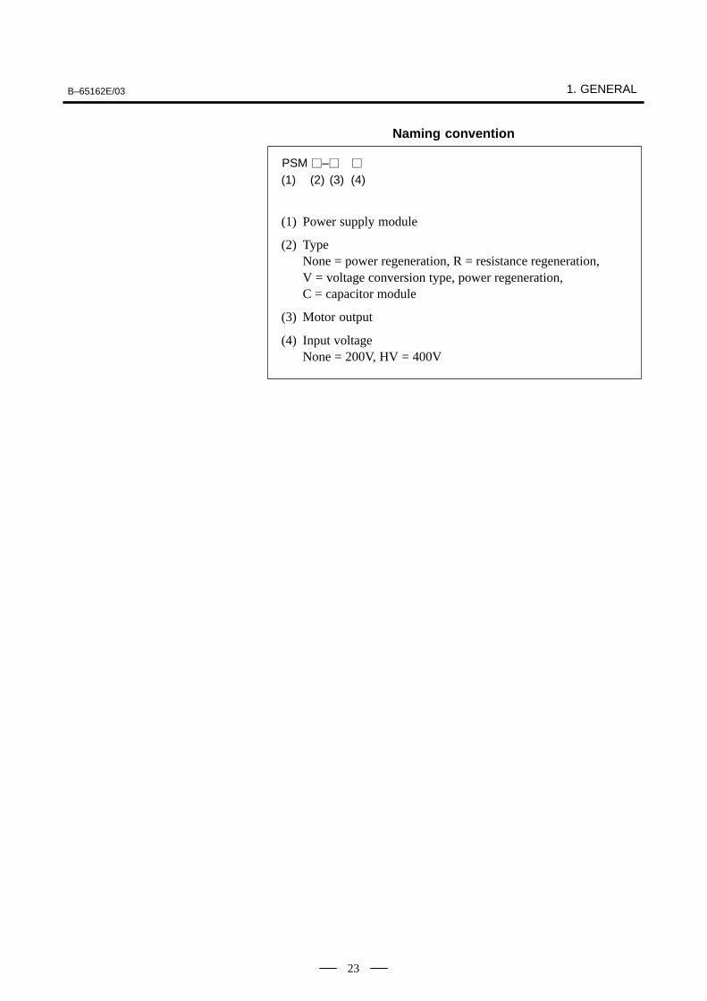
Naming convention
PSM –
(1) (2) (3) (4)
(1) Power supply module
(2) TypeNone = power regeneration, R = resistance regeneration, V = voltage conversion type, power regeneration, C = capacitor module
(3) Motor output
(4) Input voltageNone = 200V, HV = 400V
1. GENERAL B–65162E/03
24
The servo amplifier module drives a servo motor. Select a servo amplifiermodule according to the servo motor being used.There are two types of servo amplifier module, as follows:
(1) Servo amplifier module (SVM)
This module drives a servo motor of the 200–V input series. Modules forone axis, two axes, and three axes are available. As the interface with theCNC, three types of interface are used: Type A, type B, and FSSB.
(2) Servo amplifier module (SVM–HV)
This module drives a servo motor of the 400–V input series. Modules forone axis and two axes are available. As the interface with the CNC, threetypes of interface are used: Type A, type B, and FSSB.
Check the interface of the CNC being used, and select an appropriateservo amplifier module.
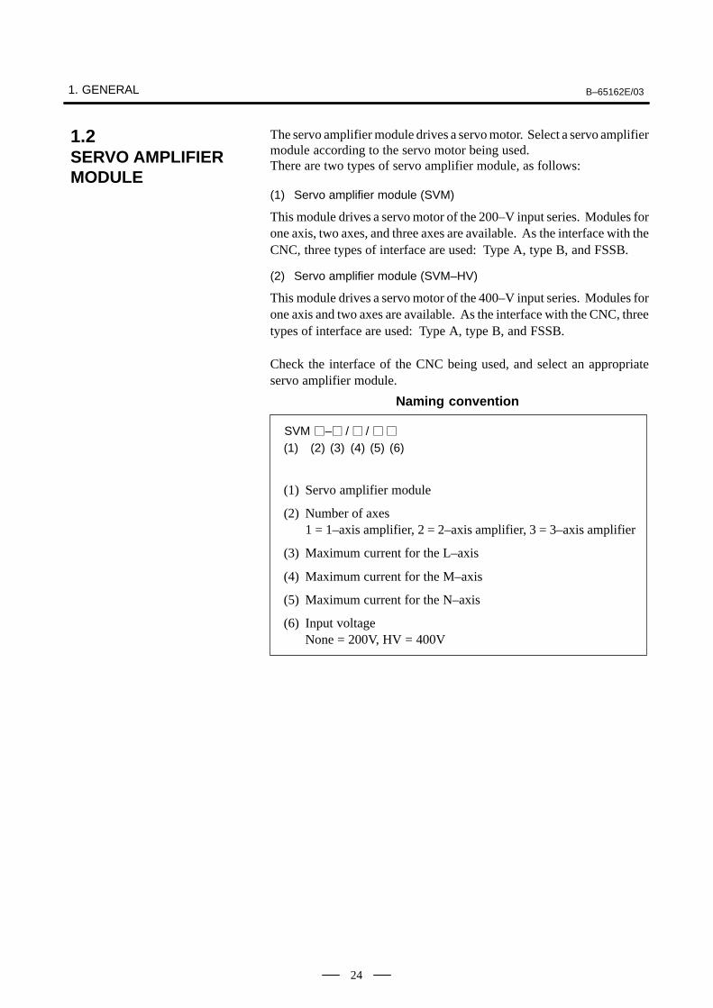
Naming convention
SVM – / /
(1) (2) (3) (4)
(1) Servo amplifier module
(2) Number of axes1 = 1–axis amplifier, 2 = 2–axis amplifier, 3 = 3–axis amplifier
(3) Maximum current for the L–axis
(4) Maximum current for the M–axis
(5) Maximum current for the N–axis
(6) Input voltageNone = 200V, HV = 400V
(5) (6)
1.2SERVO AMPLIFIER MODULE
B–65162E/03 1. GENERAL
25
The spindle amplifier module drives a spindle motor. Select a spindleamplifier module according to the spindle motor being used.There are three types of spindle amplifier module, as follows:
(1) Spindle amplifier module (SPM)
This module drives a spindle motor of the 200–V input series.
(2) Spindle amplifier module (SPMC)
This module drives the αC series spindle motor.
(3) Spindle amplifier module (SPM–HV)
This module drives a spindle motor of the 400V input series.
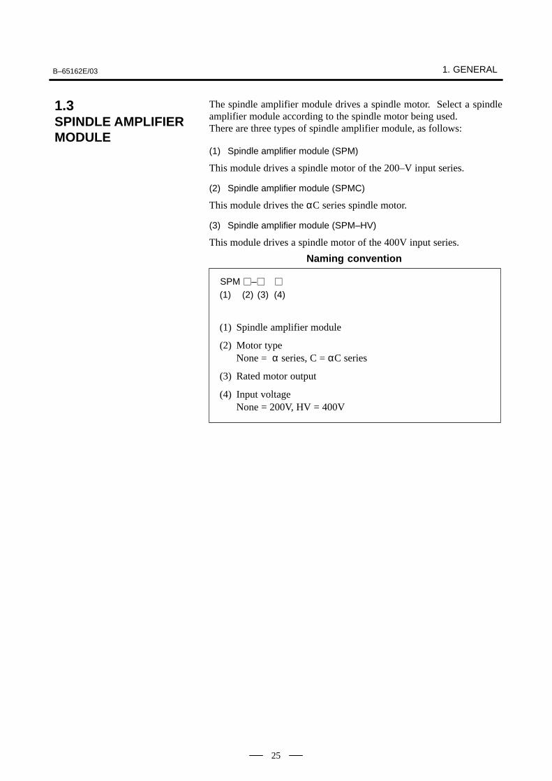
Naming convention
SPM –
(1) (2) (3) (4)
(1) Spindle amplifier module
(2) Motor typeNone = α series, C = αC series
(3) Rated motor output
(4) Input voltageNone = 200V, HV = 400V
1.3SPINDLE AMPLIFIER MODULE
1. GENERAL B–65162E/03
26
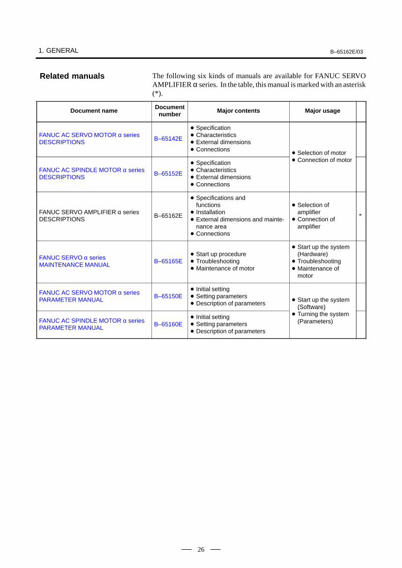
The following six kinds of manuals are available for FANUC SERVOAMPLIFIER α series. In the table, this manual is marked with an asterisk(*).
Document name Documentnumber Major contents Major usage
FANUC AC SERVO MOTOR α seriesDESCRIPTIONS
B–65142E
Specification Characteristics External dimensions Connections
Selection of motor
FANUC AC SPINDLE MOTOR α seriesDESCRIPTIONS
B–65152E
Specification Characteristics External dimensions Connections
Selection of motor Connection of motor
FANUC SERVO AMPLIFIER α seriesDESCRIPTIONS
B–65162E
Specifications andfunctions
Installation External dimensions and mainte-
nance area Connections
Selection of amplifier
Connection of amplifier
*
FANUC SERVO α seriesMAINTENANCE MANUAL
B–65165E Start up procedure Troubleshooting Maintenance of motor
Start up the system(Hardware)
Troubleshooting Maintenance of
motor
FANUC AC SERVO MOTOR α seriesPARAMETER MANUAL
B–65150E Initial setting Setting parameters Description of parameters
Start up the system(Software)
FANUC AC SPINDLE MOTOR α seriesPARAMETER MANUAL
B–65160E Initial setting Setting parameters Description of parameters
(Software) Turning the system
(Parameters)
Related manuals

B–65162E/03
27
2
B–65162E/03
28
The FANUC series consists of the following units and parts:
(1) Power supply module (PSM) (Basic)(2) Power supply module (register discharge type) (PSMR) (Basic)(3) Servo amplifier module (SVM) (Basic)(4) Spindle amplifier module (SPM) (Basic)(5) Spindle amplifier module (SPMC) (Basic)(6) AC reactor (Basic)(7) Connectors (for connection cables) (Basic)(8) Fuses (Basic)(9) Power transformer (Optional)(10) Fan adaptor (Optional)(11) AC line filter (Basic)(12) Regenerative discharge unit (Basic)(13) Dynamic brake module (DBM) (Basic)
2.1CONFIGURATION
2.1.1200–V Input Series
B–65162E/03
29
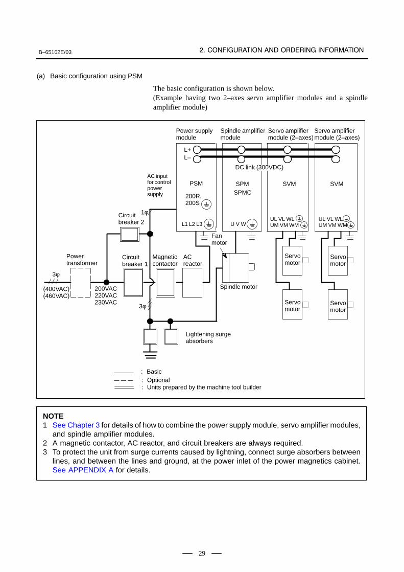
(a) Basic configuration using PSM
The basic configuration is shown below.(Example having two 2–axes servo amplifier modules and a spindleamplifier module)
L+L–
PSM SPM SVM SVM
200R,200S
L1 L2 L3 U V WUL VL WLUM VM WM
UL VL WLUM VM WM
Power supply module
Spindle amplifiermodule
Servo amplifiermodule (2–axes)
Servo amplifiermodule (2–axes)
(400VAC)(460VAC)
ÃÃÃÃÃÃÃÃÃÃÃÃDC link (300VDC)
AC inputfor controlpowersupply
Circuit breaker 1
Power transformer
200VAC220VAC230VAC
Magnetic contactor
AC reactor
Spindle motor
Servomotor
Servomotor
Servomotor
Servomotor
Fan motor
: Basic: Optional: Units prepared by the machine tool builder
Circuit breaker 2
Lightening surgeabsorbers
ÃÃÃÃ
ÃÃÃÃÃÃÃÃ
ÃÃÃÃÃÃÃÃ
ÃÃÃÃÃÃÃÃ
SPMC
3φ
3φ
1φ
ÃÃÃÃÃÃ
ÃÃÃÃ
ÃÃÃÃÃÃÃ
ÃÃÃÃ
NOTE1 See Chapter 3 for details of how to combine the power supply module, servo amplifier modules,
and spindle amplifier modules.2 A magnetic contactor, AC reactor, and circuit breakers are always required.3 To protect the unit from surge currents caused by lightning, connect surge absorbers between
lines, and between the lines and ground, at the power inlet of the power magnetics cabinet.See APPENDIX A for details.
B–65162E/03
30
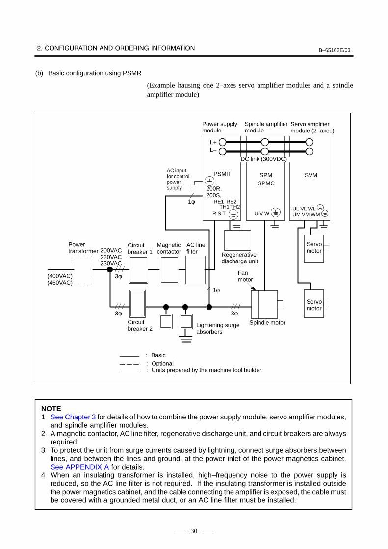
(b) Basic configuration using PSMR
(Example hausing one 2–axes servo amplifier modules and a spindleamplifier module)
L+L–
PSMR SPM SVM
200R,200S,
R S T U V WUL VL WLUM VM WM
Power supply module
Spindle amplifiermodule
Servo amplifiermodule (2–axes)
(400VAC)(460VAC)
ÃÃÃÃÃÃÃÃÃÃÃÃÃÃ
DC link (300VDC)
AC inputfor controlpowersupply
Circuit breaker 1
Power transformer 200VAC
220VAC230VAC
Magnetic contactor
AC linefilter
Spindle motor
Servomotor
Servomotor
Fan motor
: Basic: Optional: Units prepared by the machine tool builder
Lightening surgeabsorbers
ÃÃÃÃÃÃÃÃ
ÃÃÃÃÃÃÃÃ
ÃÃÃÃ
SPMC
1φ
ÃÃÃÃÃÃÃÃÃÃÃÃ
3φ
3φ
1φ
3φ
Regenerativedischarge unit
RE1 RE2TH1 TH2
Circuit breaker 2
ÃÃÃÃ
ÃÃÃÃÃÃÃ
ÃÃÃÃÃÃ
NOTE1 See Chapter 3 for details of how to combine the power supply module, servo amplifier modules,
and spindle amplifier modules.2 A magnetic contactor, AC line filter, regenerative discharge unit, and circuit breakers are always
required.3 To protect the unit from surge currents caused by lightning, connect surge absorbers between
lines, and between the lines and ground, at the power inlet of the power magnetics cabinet.See APPENDIX A for details.
4 When an insulating transformer is installed, high–frequency noise to the power supply isreduced, so the AC line filter is not required. If the insulating transformer is installed outsidethe power magnetics cabinet, and the cable connecting the amplifier is exposed, the cable mustbe covered with a grounded metal duct, or an AC line filter must be installed.
B–65162E/03
31
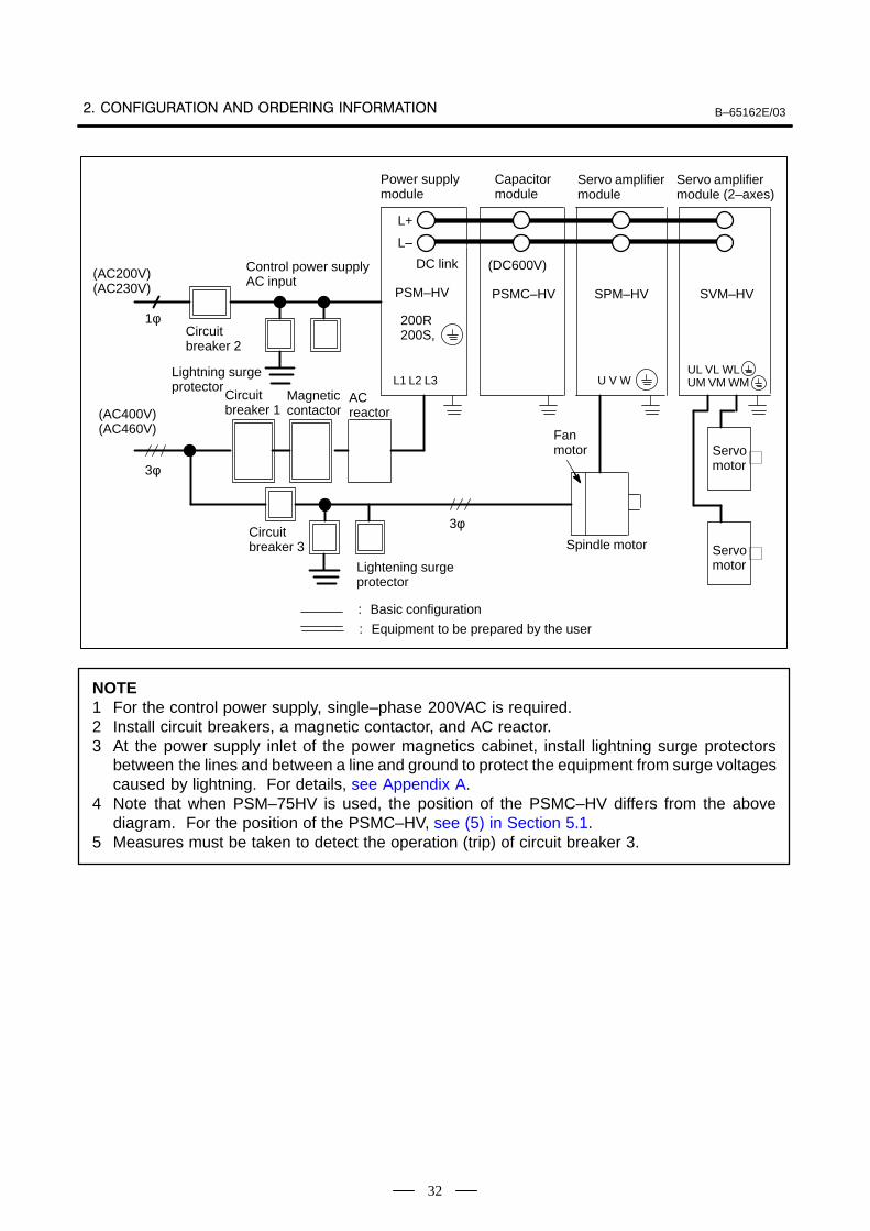
(a) Basic configuration using a PSM–HV
(1) Power supply module (PSM–HV) (Basic)(2) Capacitor module (PSMC–HV) (Basic)(3) Servo amplifier module (SVM–HV) (Basic)(4) Spindle amplifier module (SPM–HV) (Basic)(5) AC reactor (Basic)(6) Connectors (for cables) (Basic)(7) Fuses (Basic)(8) Fan adaptor (Optional)
(The following example uses one 2–axis servo amplifier module and onespindle amplifier module.)
2.1.2400–V Input Series
B–65162E/03
32
Servo amplifiermodule
L+
L–
PSM–HV PSMC–HV SPM–HV SVM–HV
200R200S,
L1 L2 L3 U V WUL VL WLUM VM WM
Power supply module
Capacitor module
Servo amplifiermodule (2–axes)
(AC400V)(AC460V)
DC link
Circuit breaker 1
AC reactor
Spindle motor Servomotor
Servomotor
Fan motor
: Basic configuration
: Equipment to be prepared by the user
Lightening surgeprotector
ÃÃÃÃÃÃÃÃ
ÃÃÃÃÃÃÃÃ
ÃÃÃÃÃÃÃÃ
ÃÃÃÃÃÃÃÃ (DC600V)
(AC200V)(AC230V)
3φ
1φ
Control power supplyAC input
Lightning surgeprotector
Magneticcontactor
Circuitbreaker 2
ÃÃÃÃ
ÃÃÃÃ
ÃÃÃÃ
ÃÃÃÃ
Circuitbreaker 3
3φ
NOTE1 For the control power supply, single–phase 200VAC is required.2 Install circuit breakers, a magnetic contactor, and AC reactor.3 At the power supply inlet of the power magnetics cabinet, install lightning surge protectors
between the lines and between a line and ground to protect the equipment from surge voltagescaused by lightning. For details, see Appendix A.
4 Note that when PSM–75HV is used, the position of the PSMC–HV differs from the abovediagram. For the position of the PSMC–HV, see (5) in Section 5.1.
5 Measures must be taken to detect the operation (trip) of circuit breaker 3.
B–65162E/03
33
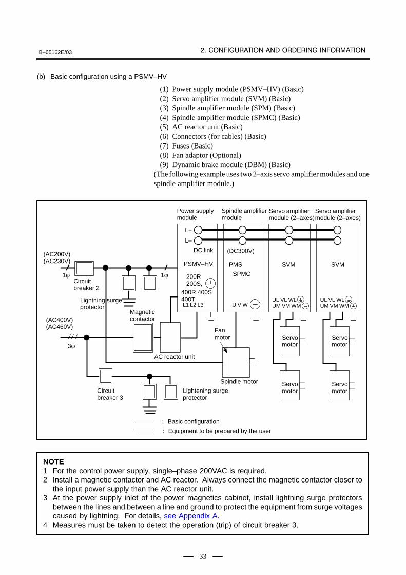
(b) Basic configuration using a PSMV–HV
(1) Power supply module (PSMV–HV) (Basic)(2) Servo amplifier module (SVM) (Basic)(3) Spindle amplifier module (SPM) (Basic)(4) Spindle amplifier module (SPMC) (Basic)(5) AC reactor unit (Basic)(6) Connectors (for cables) (Basic)(7) Fuses (Basic)(8) Fan adaptor (Optional)(9) Dynamic brake module (DBM) (Basic)
(The following example uses two 2–axis servo amplifier modules and onespindle amplifier module.)
Servo amplifiermodule (2–axes)
L+
L–
PSMV–HV PMS SVM SVM
200R200S,
L1 L2 L3 U V WUL VL WLUM VM WM
Power supply module
Spindle amplifier module
Servo amplifiermodule (2–axes)
DC link
Spindle motor Servomotor
Servomotor
Fan motor
ÃÃ
ÃÃÃÃ
ÃÃÃÃ
ÃÃÃÃ
(DC300V)
ÃÃÃÃ
ÃÃÃÃ
ÃÃÃÃ
ÃÃÃÃ
UL VL WLUM VM WMÃ
Ã
ÃÃÃÃ
Servomotor
Servomotor
(AC400V)(AC460V)
Lightening surgeprotector
(AC200V)(AC230V)
3φ
1φ
Lightning surgeprotector
Circuitbreaker 2
Circuitbreaker 3
SPMC
400R,400S400T
1φ
Magneticcontactor
AC reactor unit
: Basic configuration
: Equipment to be prepared by the user
NOTE1 For the control power supply, single–phase 200VAC is required.2 Install a magnetic contactor and AC reactor. Always connect the magnetic contactor closer to
the input power supply than the AC reactor unit.3 At the power supply inlet of the power magnetics cabinet, install lightning surge protectors
between the lines and between a line and ground to protect the equipment from surge voltagescaused by lightning. For details, see Appendix A.
4 Measures must be taken to detect the operation (trip) of circuit breaker 3.
B–65162E/03
34
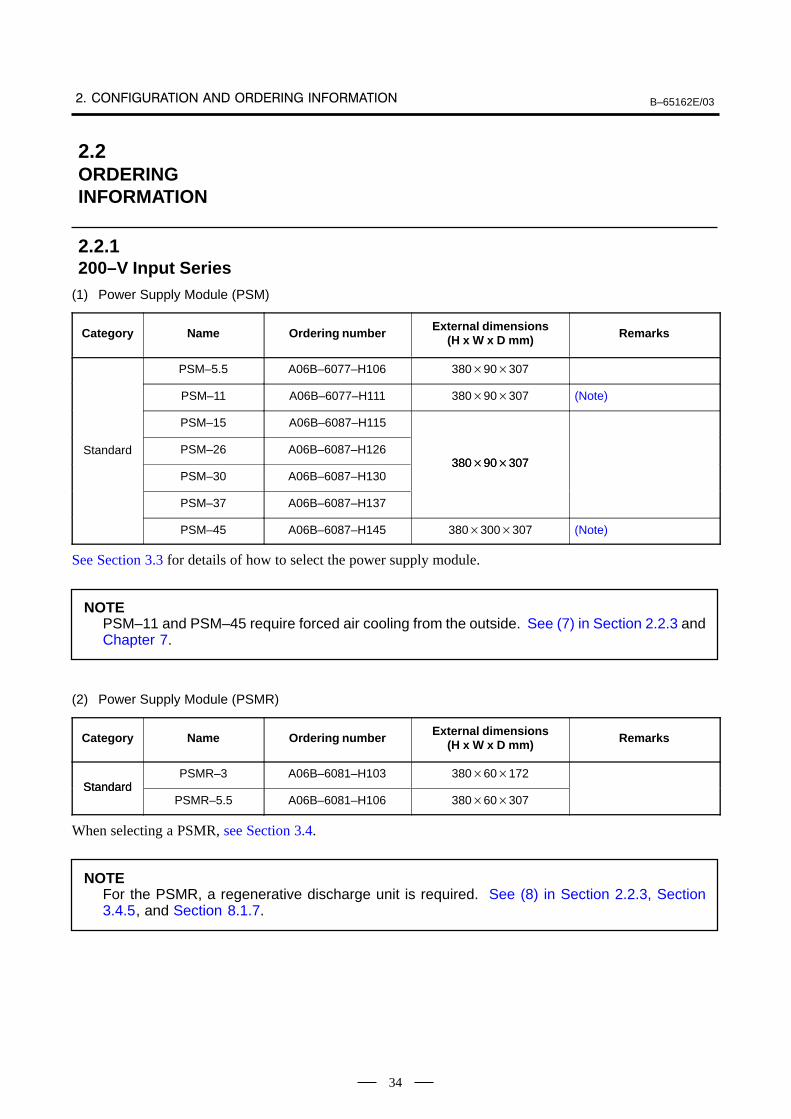
(1) Power Supply Module (PSM)
Category Name Orderin g number External dimensions(H x W x D mm) Remarks
PSM–5.5 A06B–6077–H106 38090307
PSM–11 A06B–6077–H111 38090307 (Note)
PSM–15 A06B–6087–H115
Standard PSM–26 A06B–6087–H12638090307
PSM–30 A06B–6087–H13038090307
PSM–37 A06B–6087–H137
PSM–45 A06B–6087–H145 380300307 (Note)
See Section 3.3 for details of how to select the power supply module.
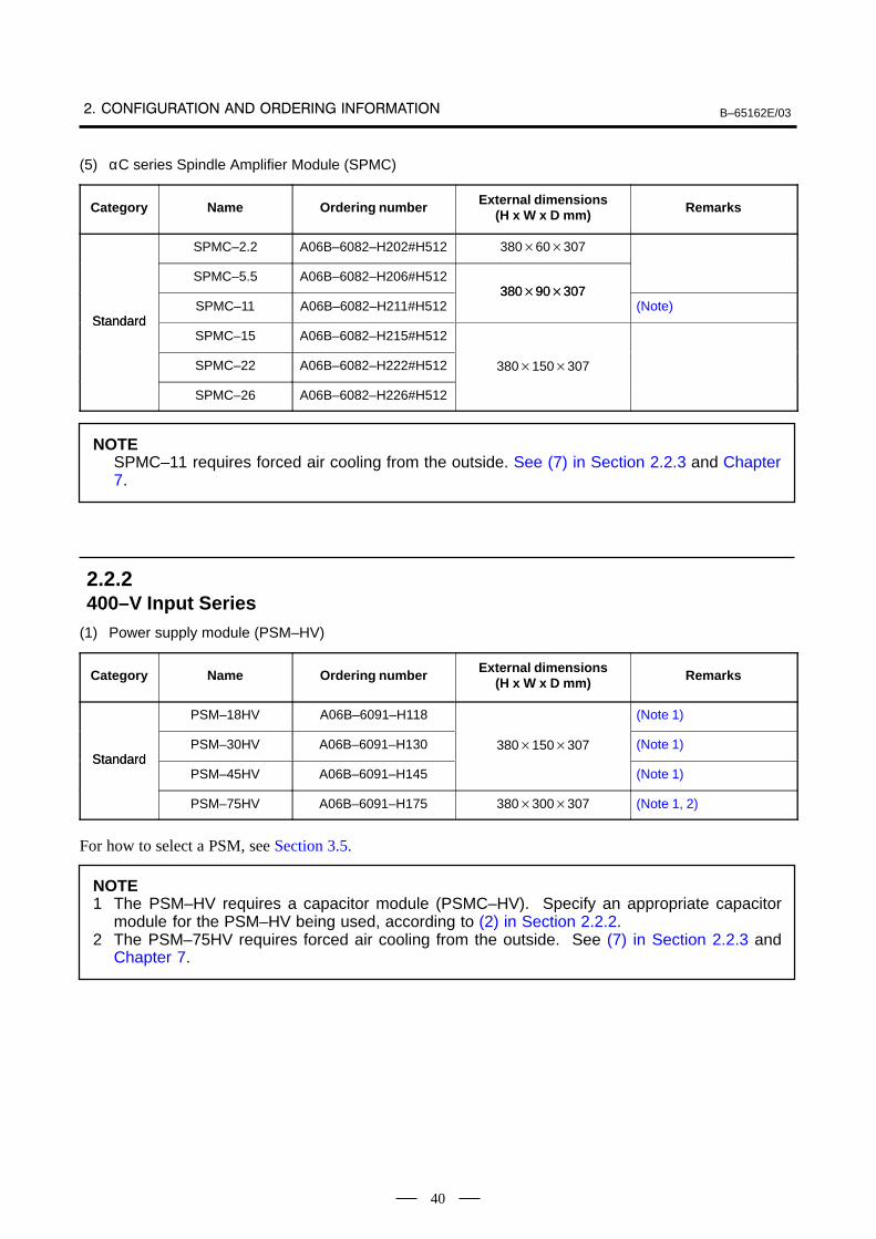
NOTEPSM–11 and PSM–45 require forced air cooling from the outside. See (7) in Section 2.2.3 andChapter 7.
(2) Power Supply Module (PSMR)
Category Name Orderin g number External dimensions(H x W x D mm) Remarks
StandardPSMR–3 A06B–6081–H103 38060172
StandardPSMR–5.5 A06B–6081–H106 38060307
When selecting a PSMR, see Section 3.4.
NOTEFor the PSMR, a regenerative discharge unit is required. See (8) in Section 2.2.3, Section3.4.5, and Section 8.1.7.
2.2ORDERINGINFORMATION
2.2.1200–V Input Series
B–65162E/03
35
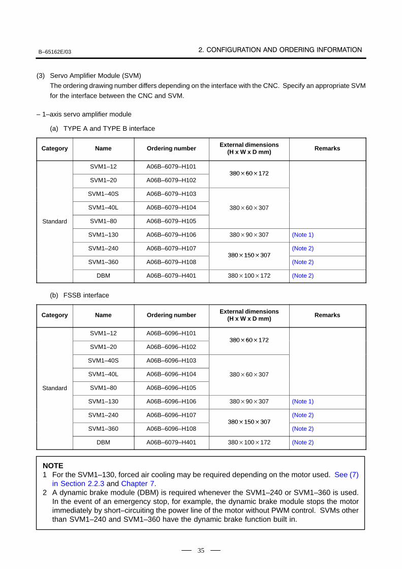
(3) Servo Amplifier Module (SVM)
The ordering drawing number differs depending on the interface with the CNC. Specify an appropriate SVM
for the interface between the CNC and SVM.
– 1–axis servo amplifier module
(a) TYPE A and TYPE B interface
Category Name Ordering number External dimensions(H x W x D mm) Remarks
SVM1–12 A06B–6079–H10138060172
SVM1–20 A06B–6079–H10238060172
SVM1–40S A06B–6079–H103
SVM1–40L A06B–6079–H104 38060307
Standard SVM1–80 A06B–6079–H105
SVM1–130 A06B–6079–H106 38090307 (Note 1)
SVM1–240 A06B–6079–H107380150307
(Note 2)
SVM1–360 A06B–6079–H108380150307
(Note 2)
DBM A06B–6079–H401 380100172 (Note 2)
(b) FSSB interface
Category Name Ordering number External dimensions(H x W x D mm) Remarks
SVM1–12 A06B–6096–H10138060172
SVM1–20 A06B–6096–H10238060172
SVM1–40S A06B–6096–H103
SVM1–40L A06B–6096–H104 38060307
Standard SVM1–80 A06B–6096–H105
SVM1–130 A06B–6096–H106 38090307 (Note 1)
SVM1–240 A06B–6096–H107380150307
(Note 2)
SVM1–360 A06B–6096–H108380150307
(Note 2)
DBM A06B–6079–H401 380100172 (Note 2)
NOTE1 For the SVM1–130, forced air cooling may be required depending on the motor used. See (7)
in Section 2.2.3 and Chapter 7.2 A dynamic brake module (DBM) is required whenever the SVM1–240 or SVM1–360 is used.
In the event of an emergency stop, for example, the dynamic brake module stops the motorimmediately by short–circuiting the power line of the motor without PWM control. SVMs otherthan SVM1–240 and SVM1–360 have the dynamic brake function built in.
B–65162E/03
36
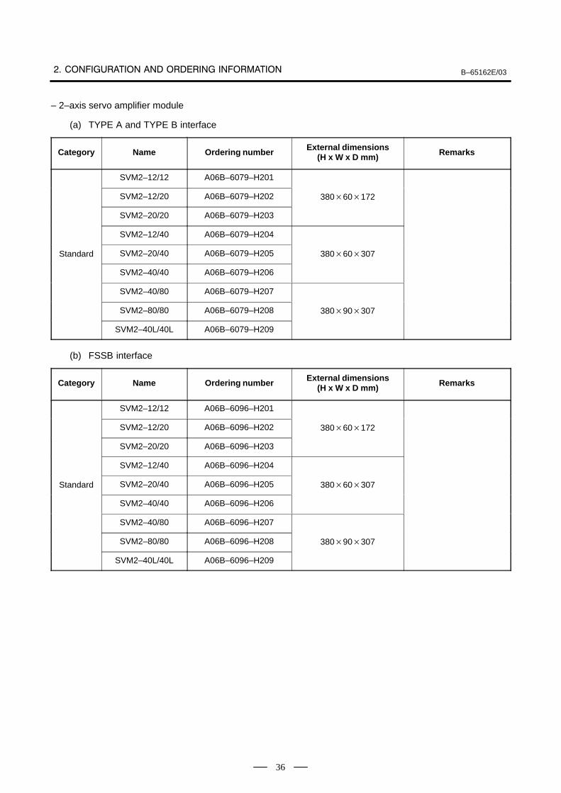
– 2–axis servo amplifier module
(a) TYPE A and TYPE B interface
Category Name Ordering number External dimensions(H x W x D mm) Remarks
SVM2–12/12 A06B–6079–H201
SVM2–12/20 A06B–6079–H202 38060172
SVM2–20/20 A06B–6079–H203
SVM2–12/40 A06B–6079–H204
Standard SVM2–20/40 A06B–6079–H205 38060307
SVM2–40/40 A06B–6079–H206
SVM2–40/80 A06B–6079–H207
SVM2–80/80 A06B–6079–H208 38090307
SVM2–40L/40L A06B–6079–H209
(b) FSSB interface
Category Name Ordering number External dimensions(H x W x D mm) Remarks
SVM2–12/12 A06B–6096–H201
SVM2–12/20 A06B–6096–H202 38060172
SVM2–20/20 A06B–6096–H203
SVM2–12/40 A06B–6096–H204
Standard SVM2–20/40 A06B–6096–H205 38060307
SVM2–40/40 A06B–6096–H206
SVM2–40/80 A06B–6096–H207
SVM2–80/80 A06B–6096–H208 38090307
SVM2–40L/40L A06B–6096–H209
B–65162E/03
37
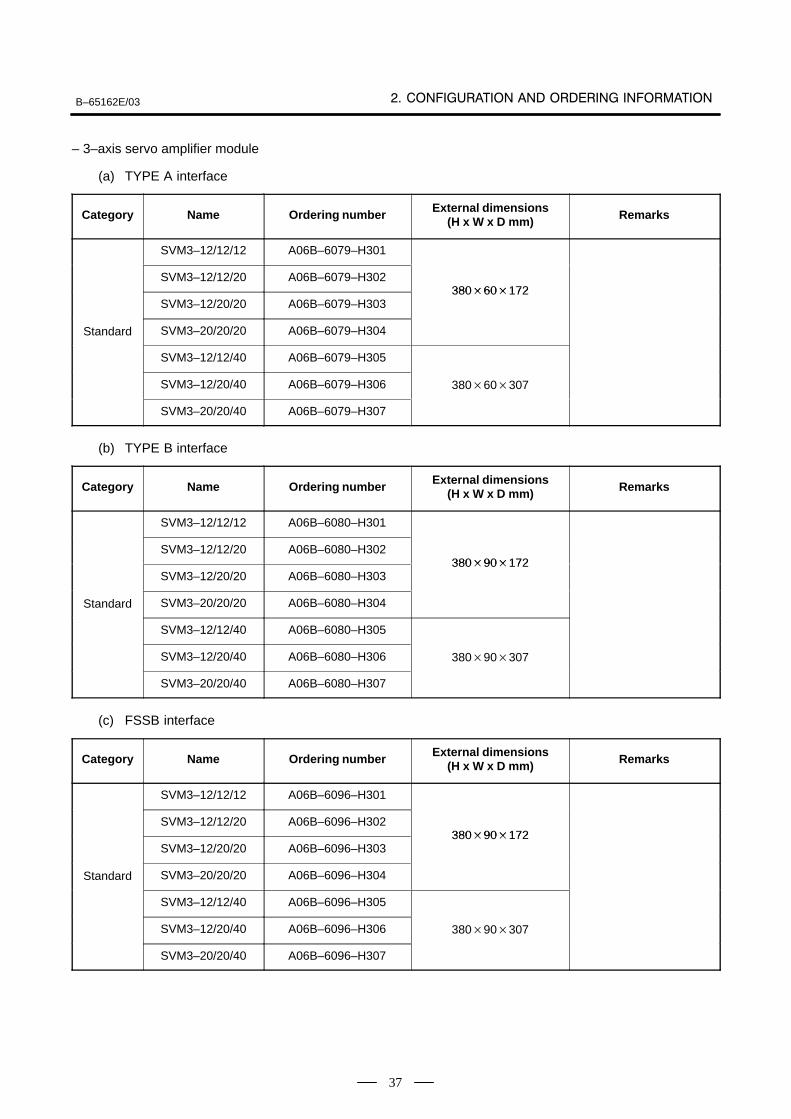
– 3–axis servo amplifier module
(a) TYPE A interface
Category Name Ordering number External dimensions(H x W x D mm) Remarks
SVM3–12/12/12 A06B–6079–H301
SVM3–12/12/20 A06B–6079–H30238060172
SVM3–12/20/20 A06B–6079–H30338060172
Standard SVM3–20/20/20 A06B–6079–H304
SVM3–12/12/40 A06B–6079–H305
SVM3–12/20/40 A06B–6079–H306 38060307
SVM3–20/20/40 A06B–6079–H307
(b) TYPE B interface
Category Name Ordering number External dimensions(H x W x D mm) Remarks
SVM3–12/12/12 A06B–6080–H301
SVM3–12/12/20 A06B–6080–H30238090172
SVM3–12/20/20 A06B–6080–H30338090172
Standard SVM3–20/20/20 A06B–6080–H304
SVM3–12/12/40 A06B–6080–H305
SVM3–12/20/40 A06B–6080–H306 38090307
SVM3–20/20/40 A06B–6080–H307
(c) FSSB interface
Category Name Ordering number External dimensions(H x W x D mm) Remarks
SVM3–12/12/12 A06B–6096–H301
SVM3–12/12/20 A06B–6096–H30238090172
SVM3–12/20/20 A06B–6096–H30338090172
Standard SVM3–20/20/20 A06B–6096–H304
SVM3–12/12/40 A06B–6096–H305
SVM3–12/20/40 A06B–6096–H306 38090307
SVM3–20/20/40 A06B–6096–H307
B–65162E/03
38
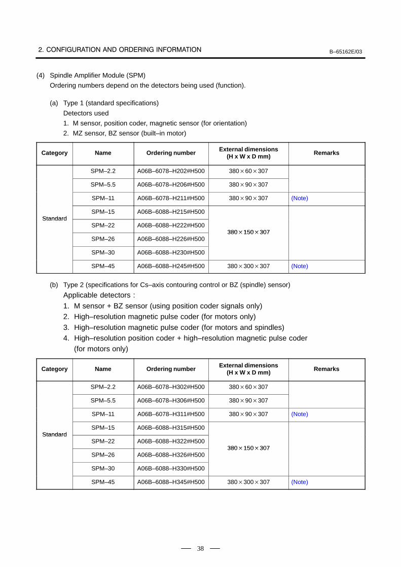
(4) Spindle Amplifier Module (SPM)
Ordering numbers depend on the detectors being used (function).
(a) Type 1 (standard specifications)
Detectors used
1. M sensor, position coder, magnetic sensor (for orientation)
2. MZ sensor, BZ sensor (built–in motor)
Category Name Ordering number External dimensions(H x W x D mm) Remarks
SPM–2.2 A06B–6078–H202#H500 38060307
SPM–5.5 A06B–6078–H206#H500 38090307
SPM–11 A06B–6078–H211#H500 38090307 (Note)
StandardSPM–15 A06B–6088–H215#H500
StandardSPM–22 A06B–6088–H222#H500
380150307SPM–26 A06B–6088–H226#H500
380150307
SPM–30 A06B–6088–H230#H500
SPM–45 A06B–6088–H245#H500 380300307 (Note)
(b) Type 2 (specifications for Cs–axis contouring control or BZ (spindle) sensor)
Applicable detectors :
1. M sensor + BZ sensor (using position coder signals only)2. High–resolution magnetic pulse coder (for motors only)
3. High–resolution magnetic pulse coder (for motors and spindles)4. High–resolution position coder + high–resolution magnetic pulse coder (for motors only)
Category Name Ordering number External dimensions(H x W x D mm) Remarks
SPM–2.2 A06B–6078–H302#H500 38060307
SPM–5.5 A06B–6078–H306#H500 38090307
SPM–11 A06B–6078–H311#H500 38090307 (Note)
StandardSPM–15 A06B–6088–H315#H500
StandardSPM–22 A06B–6088–H322#H500
380150307SPM–26 A06B–6088–H326#H500
380150307
SPM–30 A06B–6088–H330#H500
SPM–45 A06B–6088–H345#H500 380300307 (Note)
B–65162E/03
39
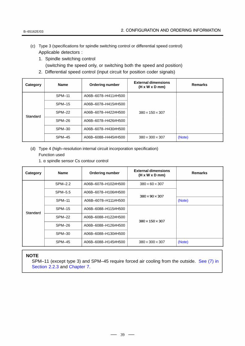
(c) Type 3 (specifications for spindle switching control or differential speed control)
Applicable detectors :1. Spindle switching control
(switching the speed only, or switching both the speed and position)2. Differential speed control (input circuit for position coder signals)
Category Name Ordering number External dimensions(H x W x D mm) Remarks
SPM–11 A06B–6078–H411#H500
SPM–15 A06B–6078–H415#H500
StandardSPM–22 A06B–6078–H422#H500 380150307
StandardSPM–26 A06B–6078–H426#H500
SPM–30 A06B–6078–H430#H500
SPM–45 A06B–6088–H445#H500 380300307 (Note)
(d) Type 4 (high–resolution internal circuit incorporation specification)
Function used
1. α spindle sensor Cs contour control
Category Name Ordering number External dimensions(H x W x D mm) Remarks
SPM–2.2 A06B–6078–H102#H500 38060307
SPM–5.5 A06B–6078–H106#H50038090307
SPM–11 A06B–6078–H111#H50038090307
(Note)
StandardSPM–15 A06B–6088–H115#H500
StandardSPM–22 A06B–6088–H122#H500
380150307SPM–26 A06B–6088–H126#H500
380150307
SPM–30 A06B–6088–H130#H500
SPM–45 A06B–6088–H145#H500 380300307 (Note)
NOTESPM–11 (except type 3) and SPM–45 require forced air cooling from the outside. See (7) inSection 2.2.3 and Chapter 7.
B–65162E/03
40
(5) αC series Spindle Amplifier Module (SPMC)
Category Name Orderin g number External dimensions(H x W x D mm) Remarks
SPMC–2.2 A06B–6082–H202#H512 38060307
SPMC–5.5 A06B–6082–H206#H51238090307
StandardSPMC–11 A06B–6082–H211#H512
38090307(Note)
StandardSPMC–15 A06B–6082–H215#H512
SPMC–22 A06B–6082–H222#H512 380150307
SPMC–26 A06B–6082–H226#H512
NOTESPMC–11 requires forced air cooling from the outside. See (7) in Section 2.2.3 and Chapter7.
(1) Power supply module (PSM–HV)
Category Name Orderin g number External dimensions(H x W x D mm) Remarks
PSM–18HV A06B–6091–H118 (Note 1)
StandardPSM–30HV A06B–6091–H130 380150307 (Note 1)
StandardPSM–45HV A06B–6091–H145 (Note 1)
PSM–75HV A06B–6091–H175 380300307 (Note 1, 2)
For how to select a PSM, see Section 3.5.
NOTE1 The PSM–HV requires a capacitor module (PSMC–HV). Specify an appropriate capacitor
module for the PSM–HV being used, according to (2) in Section 2.2.2.2 The PSM–75HV requires forced air cooling from the outside. See (7) in Section 2.2.3 and
Chapter 7.
2.2.2400–V Input Series
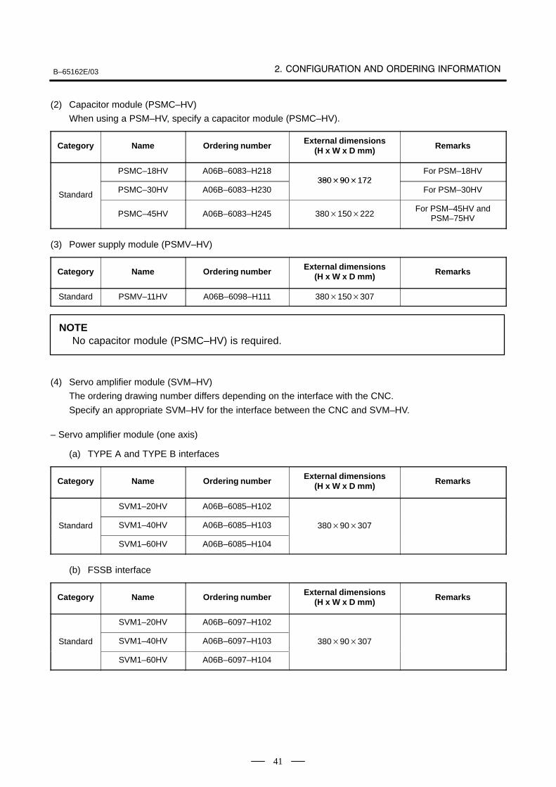
B–65162E/03
41
(2) Capacitor module (PSMC–HV)
When using a PSM–HV, specify a capacitor module (PSMC–HV).
Category Name Ordering number External dimensions(H x W x D mm) Remarks
PSMC–18HV A06B–6083–H21838090172
For PSM–18HV
StandardPSMC–30HV A06B–6083–H230
38090172For PSM–30HV
Standard
PSMC–45HV A06B–6083–H245 380150222For PSM–45HV and
PSM–75HV
(3) Power supply module (PSMV–HV)
Category Name Ordering number External dimensions(H x W x D mm) Remarks
Standard PSMV–11HV A06B–6098–H111 380150307
NOTENo capacitor module (PSMC–HV) is required.
(4) Servo amplifier module (SVM–HV)
The ordering drawing number differs depending on the interface with the CNC.
Specify an appropriate SVM–HV for the interface between the CNC and SVM–HV.
– Servo amplifier module (one axis)
(a) TYPE A and TYPE B interfaces
Category Name Ordering number External dimensions(H x W x D mm) Remarks
SVM1–20HV A06B–6085–H102
Standard SVM1–40HV A06B–6085–H103 38090307
SVM1–60HV A06B–6085–H104
(b) FSSB interface
Category Name Ordering number External dimensions(H x W x D mm) Remarks
SVM1–20HV A06B–6097–H102
Standard SVM1–40HV A06B–6097–H103 38090307
SVM1–60HV A06B–6097–H104
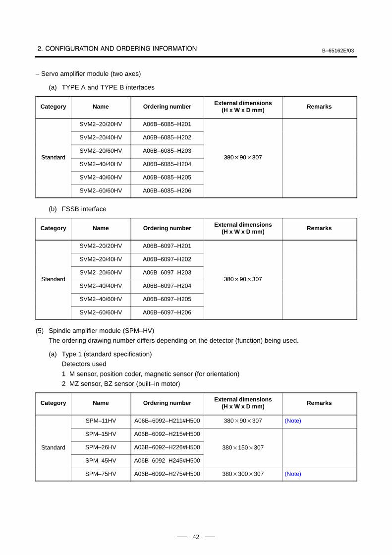
B–65162E/03
42
– Servo amplifier module (two axes)
(a) TYPE A and TYPE B interfaces
Category Name Ordering number External dimensions(H x W x D mm) Remarks
SVM2–20/20HV A06B–6085–H201
SVM2–20/40HV A06B–6085–H202
StandardSVM2–20/60HV A06B–6085–H203
38090307StandardSVM2–40/40HV A06B–6085–H204
38090307
SVM2–40/60HV A06B–6085–H205
SVM2–60/60HV A06B–6085–H206
(b) FSSB interface
Category Name Ordering number External dimensions(H x W x D mm) Remarks
SVM2–20/20HV A06B–6097–H201
SVM2–20/40HV A06B–6097–H202
StandardSVM2–20/60HV A06B–6097–H203
38090307StandardSVM2–40/40HV A06B–6097–H204
38090307
SVM2–40/60HV A06B–6097–H205
SVM2–60/60HV A06B–6097–H206
(5) Spindle amplifier module (SPM–HV)
The ordering drawing number differs depending on the detector (function) being used.
(a) Type 1 (standard specification)
Detectors used
1 M sensor, position coder, magnetic sensor (for orientation)
2 MZ sensor, BZ sensor (built–in motor)
Category Name Ordering number External dimensions(H x W x D mm) Remarks
SPM–11HV A06B–6092–H211#H500 38090307 (Note)
SPM–15HV A06B–6092–H215#H500
Standard SPM–26HV A06B–6092–H226#H500 380150307
SPM–45HV A06B–6092–H245#H500
SPM–75HV A06B–6092–H275#H500 380300307 (Note)
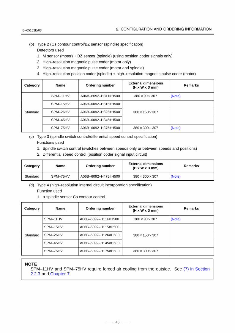
B–65162E/03
43
(b) Type 2 (Cs contour control/BZ sensor (spindle) specification)
Detectors used
1. M sensor (motor) + BZ sensor (spindle) (using position coder signals only)
2. High–resolution magnetic pulse coder (motor only)
3. High–resolution magnetic pulse coder (motor and spindle)
4. High–resolution position coder (spindle) + high–resolution magnetic pulse coder (motor)
Category Name Ordering number External dimensions(H x W x D mm) Remarks
SPM–11HV A06B–6092–H311#H500 38090307 (Note)
SPM–15HV A06B–6092–H315#H500
Standard SPM–26HV A06B–6092–H326#H500 380150307
SPM–45HV A06B–6092–H345#H500
SPM–75HV A06B–6092–H375#H500 380300307 (Note)
(c) Type 3 (spindle switch control/differential speed control specification)
Functions used
1. Spindle switch control (switches between speeds only or between speeds and positions)
2. Differential speed control (position coder signal input circuit)
Category Name Ordering number External dimensions(H x W x D mm) Remarks
Standard SPM–75HV A06B–6092–H475#H500 380300307 (Note)
(d) Type 4 (high–resolution internal circuit incorporation specification)
Function used
1. α spindle sensor Cs contour control
Category Name Ordering number External dimensions(H x W x D mm) Remarks
SPM–11HV A06B–6092–H111#H500 38090307 (Note)
SPM–15HV A06B–6092–H115#H500
Standard SPM–26HV A06B–6092–H126#H500 380150307
SPM–45HV A06B–6092–H145#H500
SPM–75HV A06B–6092–H175#H500 380300307
NOTESPM–11HV and SPM–75HV require forced air cooling from the outside. See (7) in Section2.2.3 and Chapter 7.
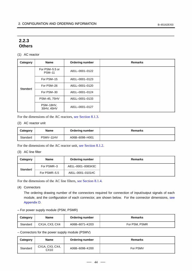
B–65162E/03
44
(1) AC reactor
Category Name Ordering number Remarks
For PSM–5.5 orPSM–11 A81L–0001–0122
For PSM–15 A81L–0001–0123
StandardFor PSM–26 A81L–0001–0120
StandardFor PSM–30 A81L–0001–0124
PSM–45, 75HV A81L–0001–0133
PSM–18HV, 30HV, 45HV A81L–0001–0127
For the dimensions of the AC reactors, see Section 8.1.3.
(2) AC reactor unit
Category Name Ordering number Remarks
Standard PSMV–11HV A06B–6098–H001
For the dimensions of the AC reactor unit, see Section 8.1.2.
(3) AC line filter
Category Name Ordering number Remarks
StandardFor PSMR–3 A81L–0001–0083#3C
StandardFor PSMR–5.5 A81L–0001–0101#C
For the dimensions of the AC line filters, see Section 8.1.4.
(4) Connectors
The ordering drawing number of the connectors required for connection of input/output signals of each
module, and the configuration of each connector, are shown below. For the connector dimensions, see
Appendix D.
– For power supply module (PSM, PSMR)
Category Name Ordering number Remarks
Standard CX1A, CX3, CX4 A06B–6071–K203 For PSM, PSMR
– Connectors for the power supply module (PSMV)
Category Name Ordering number Remarks
StandardCX1A, CX3, CX4,
CX10 A06B–6098–K200 For PSMV
2.2.3Others
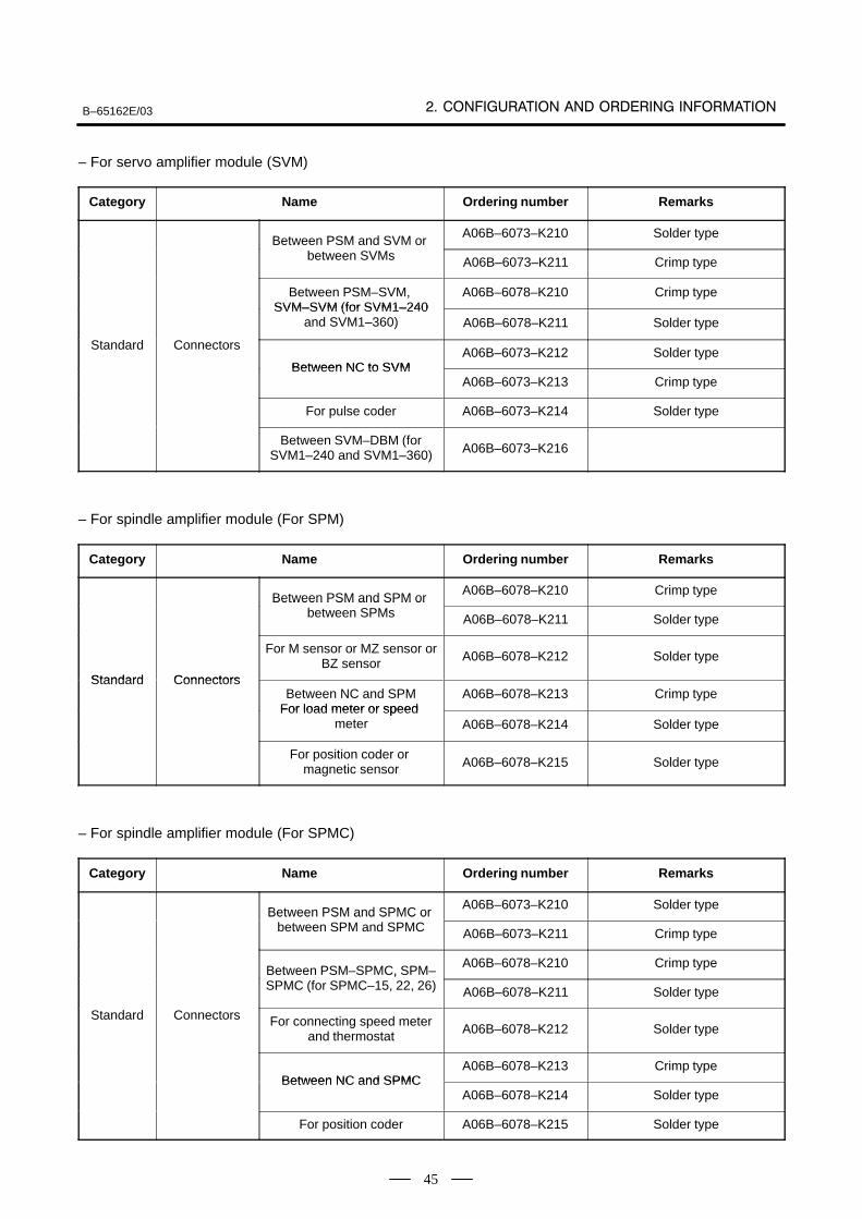
B–65162E/03
45
– For servo amplifier module (SVM)
Category Name Ordering number Remarks
Between PSM and SVM or A06B–6073–K210 Solder type
Between PSM and SVM or between SVMs A06B–6073–K211 Crimp type
Between PSM–SVM, SVM–SVM (for SVM1–240
A06B–6078–K210 Crimp typeSVM–SVM (for SVM1–240
and SVM1–360) A06B–6078–K211 Solder type
Standard Connectors
Between NC to SVMA06B–6073–K212 Solder type
Between NC to SVMA06B–6073–K213 Crimp type
For pulse coder A06B–6073–K214 Solder type
Between SVM–DBM (forSVM1–240 and SVM1–360) A06B–6073–K216
– For spindle amplifier module (For SPM)
Category Name Ordering number Remarks
Between PSM and SPM or A06B–6078–K210 Crimp type
Between PSM and SPM or between SPMs A06B–6078–K211 Solder type
Standard Connectors
For M sensor or MZ sensor orBZ sensor A06B–6078–K212 Solder type
Standard ConnectorsBetween NC and SPM
For load meter or speedA06B–6078–K213 Crimp type
For load meter or speed meter A06B–6078–K214 Solder type
For position coder or magnetic sensor A06B–6078–K215 Solder type
– For spindle amplifier module (For SPMC)
Category Name Ordering number Remarks
Between PSM and SPMC or A06B–6073–K210 Solder type
Between PSM and SPMC or between SPM and SPMC A06B–6073–K211 Crimp type
Between PSM–SPMC, SPM–A06B–6078–K210 Crimp type
Between PSM SPMC, SPMSPMC (for SPMC–15, 22, 26) A06B–6078–K211 Solder type
Standard Connectors For connecting speed meterand thermostat A06B–6078–K212 Solder type
Between NC and SPMCA06B–6078–K213 Crimp type
Between NC and SPMCA06B–6078–K214 Solder type
For position coder A06B–6078–K215 Solder type
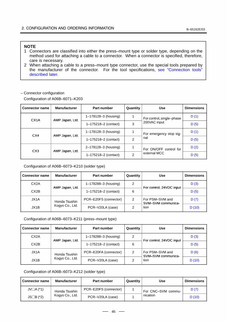
B–65162E/03
46
NOTE1 Connectors are classified into either the press–mount type or solder type, depending on the
method used for attaching a cable to a connector. When a connector is specified, therefore,care is necessary.
2 When attaching a cable to a press–mount type connector, use the special tools prepared bythe manufacturer of the connector. For the tool specifications, see ”Connection tools”described later.
– Connector configuration
Configuration of A06B–6071–K203
Connector name Manufacturer Part number Quantity Use Dimensions
CX1A AMP Japan Ltd1–178128–3 (housing) 1
For control, single–phaseD (1)
CX1A AMP Japan, Ltd.1–175218–2 (contact) 3
For control, single hase200VAC input D (5)
CX4 AMP Japan Ltd1–178128–3 (housing) 1
For emergency stop sig-D (1)
CX4 AMP Japan, Ltd.1–175218–2 (contact) 2
For emergency sto signal D (5)
CX3 AMP Japan Ltd2–178128–3 (housing) 1
For ON/OFF control forD (2)
CX3 AMP Japan, Ltd.1–175218–2 (contact) 2
For ON/OFF control forexternal MCC D (5)
Configuration of A06B–6073–K210 (solder type)
Connector name Manufacturer Part number Quantity Use Dimensions
CX2AAMP Japan Ltd
1–178288–3 (housing) 2For control 24VDC input
D (3)
CX2BAMP Japan, Ltd.
1–175218–2 (contact) 6For control, 24VDC input
D (5)
JX1AHonda Tsushin
PCR–E20FS (connector) 2 For PSM–SVM andSVM–SVM communica-
D (7)
JX1B
Honda TsushinKogyo Co., Ltd. PCR–V20LA (case) 2
SVM–SVM communica-tion D (10)
Configuration of A06B–6073–K211 (press–mount type)
Connector name Manufacturer Part number Quantity Use Dimensions
CX2AAMP Japan Ltd
1–178288–3 (housing) 2For control 24VDC input
D (3)
CX2BAMP Japan, Ltd.
1–175218–2 (contact) 6For control, 24VDC input
D (5)
JX1AHonda Tsushin
PCR–E20FA (connector) 2 For PSM–SVM andSVM–SVM communica-
D (6)
JX1B
Honda TsushinKogyo Co., Ltd. PCR–V20LA (case) 2
SVM–SVM communica-tion D (10)
Configuration of A06B–6073–K212 (solder type)
Connector name Manufacturer Part number Quantity Use Dimensions
JVA (*1)Honda Tsushin
PCR–E20FS (connector) 1For CNC–SVM commu-
D (7)
JSB (*2)
Honda TsushinKogyo Co., Ltd. PCR–V20LA (case) 1
For CNC SVM communication D (10)
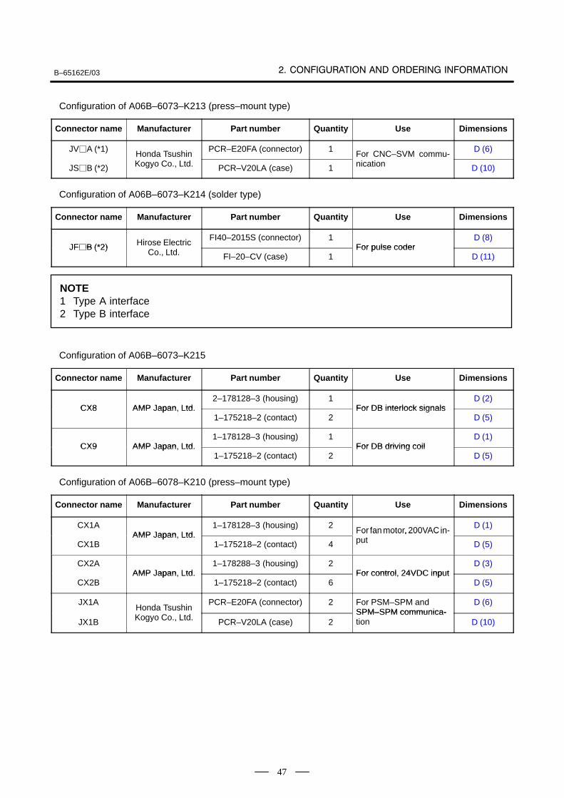
B–65162E/03
47
Configuration of A06B–6073–K213 (press–mount type)
Connector name Manufacturer Part number Quantity Use Dimensions
JVA (*1)Honda Tsushin
PCR–E20FA (connector) 1For CNC–SVM commu-
D (6)
JSB (*2)
Honda TsushinKogyo Co., Ltd. PCR–V20LA (case) 1
For CNC SVM communication D (10)
Configuration of A06B–6073–K214 (solder type)
Connector name Manufacturer Part number Quantity Use Dimensions
JFB (*2) Hirose ElectricFI40–2015S (connector) 1
For pulse coderD (8)
JFB (*2) Hirose ElectricCo., Ltd. FI–20–CV (case) 1
For pulse coderD (11)
NOTE1 Type A interface2 Type B interface
Configuration of A06B–6073–K215
Connector name Manufacturer Part number Quantity Use Dimensions
CX8 AMP Japan Ltd2–178128–3 (housing) 1
For DB interlock signalsD (2)
CX8 AMP Japan, Ltd.1–175218–2 (contact) 2
For DB interlock signalsD (5)
CX9 AMP Japan Ltd1–178128–3 (housing) 1
For DB driving coilD (1)
CX9 AMP Japan, Ltd.1–175218–2 (contact) 2
For DB driving coilD (5)
Configuration of A06B–6078–K210 (press–mount type)
Connector name Manufacturer Part number Quantity Use Dimensions
CX1AAMP Japan Ltd
1–178128–3 (housing) 2For fan motor, 200VAC in-
D (1)
CX1BAMP Japan, Ltd.
1–175218–2 (contact) 4
For fan motor, 200VAC input D (5)
CX2AAMP Japan Ltd
1–178288–3 (housing) 2For control 24VDC input
D (3)
CX2BAMP Japan, Ltd.
1–175218–2 (contact) 6For control, 24VDC input
D (5)
JX1AHonda Tsushin
PCR–E20FA (connector) 2 For PSM–SPM andSPM–SPM communica-
D (6)
JX1B
Honda TsushinKogyo Co., Ltd. PCR–V20LA (case) 2
SPM–SPM communica-tion D (10)
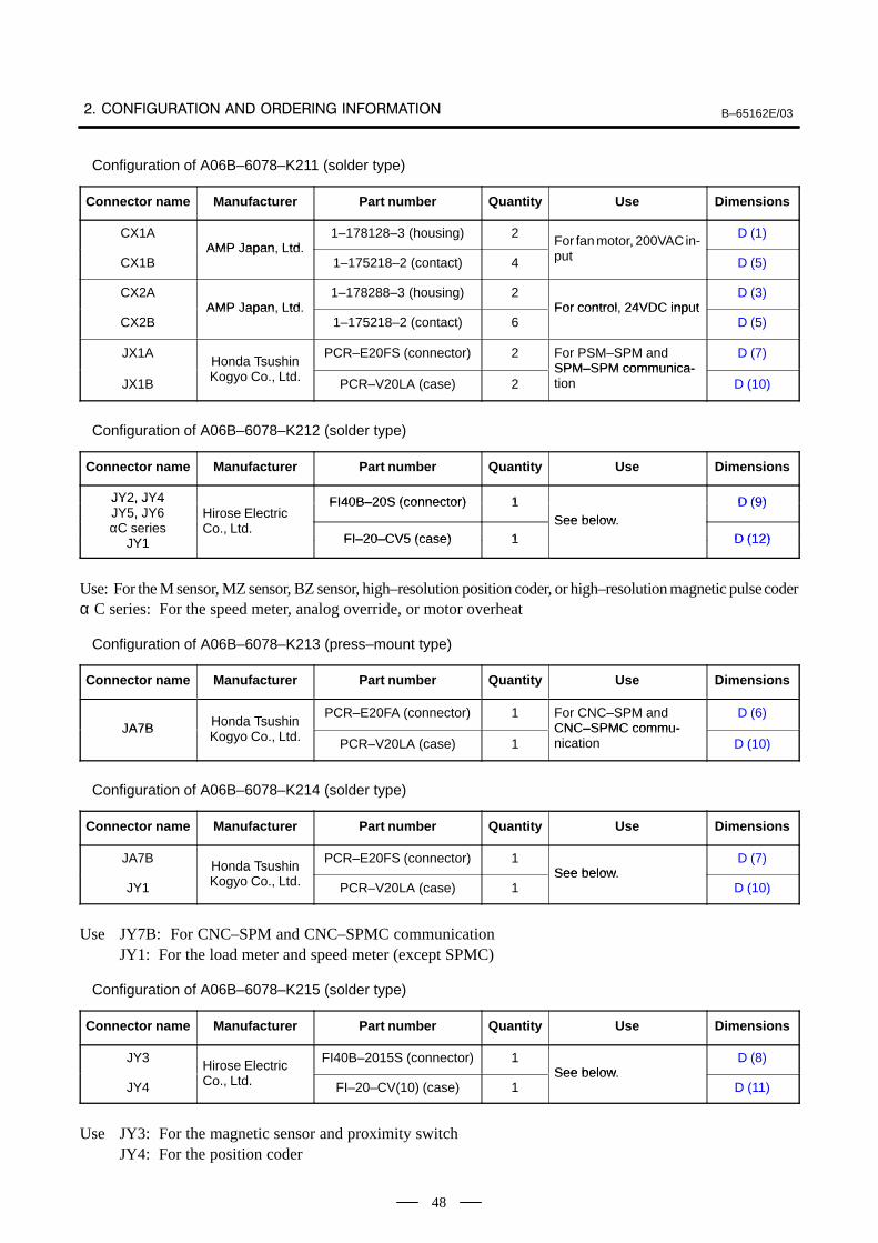
B–65162E/03
48
Configuration of A06B–6078–K211 (solder type)
Connector name Manufacturer Part number Quantity Use Dimensions
CX1AAMP Japan Ltd
1–178128–3 (housing) 2For fan motor, 200VAC in-
D (1)
CX1BAMP Japan, Ltd.
1–175218–2 (contact) 4
For fan motor, 200VAC input D (5)
CX2AAMP Japan Ltd
1–178288–3 (housing) 2For control 24VDC input
D (3)
CX2BAMP Japan, Ltd.
1–175218–2 (contact) 6For control, 24VDC input
D (5)
JX1AHonda Tsushin
PCR–E20FS (connector) 2 For PSM–SPM andSPM–SPM communica-
D (7)
JX1B
Honda TsushinKogyo Co., Ltd. PCR–V20LA (case) 2
SPM–SPM communica-tion D (10)
Configuration of A06B–6078–K212 (solder type)
Connector name Manufacturer Part number Quantity Use Dimensions
JY2, JY4 FI40B–20S (connector) 1 D (9)JY2, JY4JY5, JY6 Hirose Electric
FI40B–20S (connector) 1See below
D (9),
αC seriesJY1
Hirose ElectricCo., Ltd.
FI–20–CV5 (case) 1See below.
D (12)JY1 FI–20–CV5 (case) 1 D (12)
Use: For the M sensor, MZ sensor, BZ sensor, high–resolution position coder, or high–resolution magnetic pulse coderα C series: For the speed meter, analog override, or motor overheat
Configuration of A06B–6078–K213 (press–mount type)
Connector name Manufacturer Part number Quantity Use Dimensions
JA7B Honda TsushinPCR–E20FA (connector) 1 For CNC–SPM and
CNC–SPMC commu-D (6)
JA7B Honda TsushinKogyo Co., Ltd. PCR–V20LA (case) 1
CNC–SPMC commu-nication D (10)
Configuration of A06B–6078–K214 (solder type)
Connector name Manufacturer Part number Quantity Use Dimensions
JA7BHonda Tsushin
PCR–E20FS (connector) 1See below
D (7)
JY1
Honda TsushinKogyo Co., Ltd. PCR–V20LA (case) 1
See below.D (10)
Use JY7B: For CNC–SPM and CNC–SPMC communicationJY1: For the load meter and speed meter (except SPMC)
Configuration of A06B–6078–K215 (solder type)
Connector name Manufacturer Part number Quantity Use Dimensions
JY3Hirose Electric
FI40B–2015S (connector) 1See below
D (8)
JY4
Hirose ElectricCo., Ltd. FI–20–CV(10) (case) 1
See below.D (11)
Use JY3: For the magnetic sensor and proximity switchJY4: For the position coder
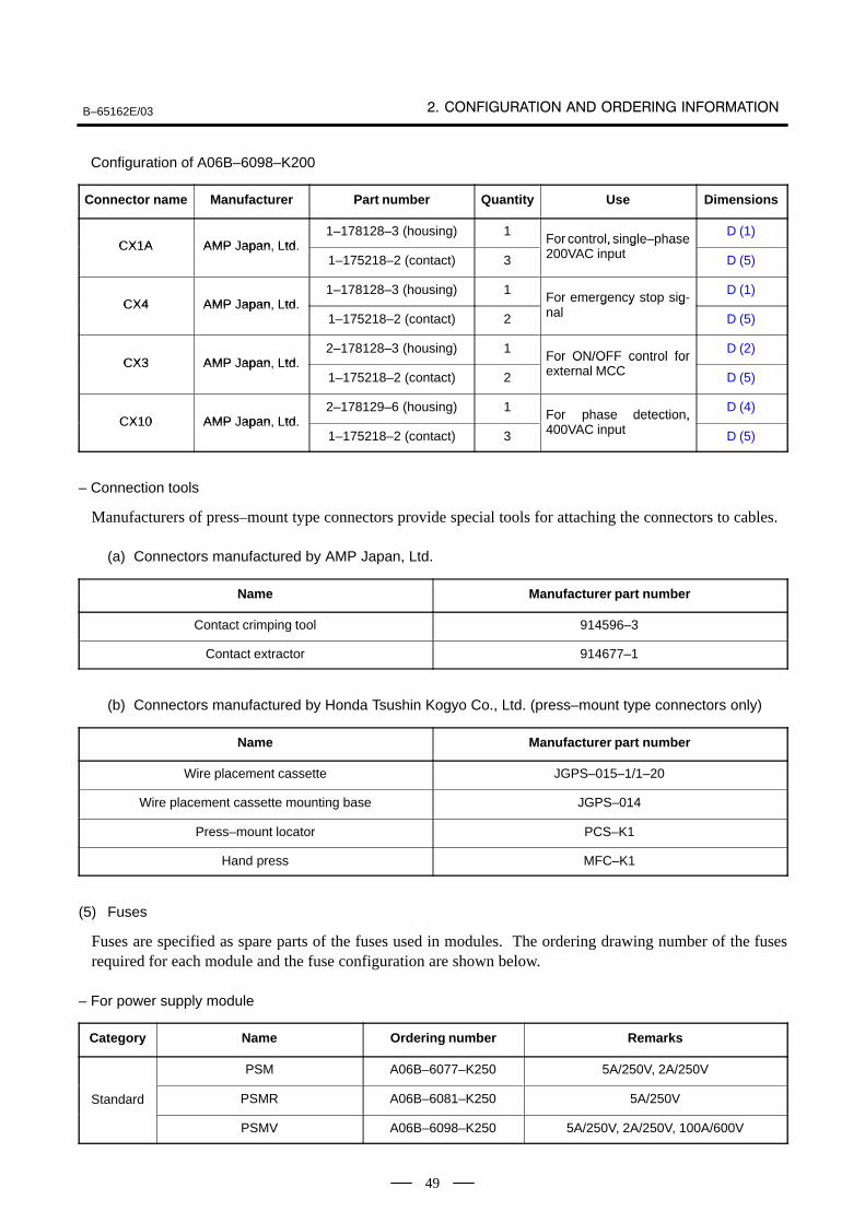
B–65162E/03
49
Configuration of A06B–6098–K200
Connector name Manufacturer Part number Quantity Use Dimensions
CX1A AMP Japan Ltd1–178128–3 (housing) 1
For control, single–phaseD (1)
CX1A AMP Japan, Ltd.1–175218–2 (contact) 3
For control, single hase200VAC input D (5)
CX4 AMP Japan Ltd1–178128–3 (housing) 1
For emergency stop sig-D (1)
CX4 AMP Japan, Ltd.1–175218–2 (contact) 2
For emergency sto signal D (5)
CX3 AMP Japan Ltd2–178128–3 (housing) 1
For ON/OFF control forD (2)
CX3 AMP Japan, Ltd.1–175218–2 (contact) 2
For ON/OFF control forexternal MCC D (5)
CX10 AMP Japan Ltd2–178129–6 (housing) 1
For phase detection,D (4)
CX10 AMP Japan, Ltd.1–175218–2 (contact) 3
For hase detection,400VAC input D (5)
– Connection tools
Manufacturers of press–mount type connectors provide special tools for attaching the connectors to cables.
(a) Connectors manufactured by AMP Japan, Ltd.
Name Manufacturer part number
Contact crimping tool 914596–3
Contact extractor 914677–1
(b) Connectors manufactured by Honda Tsushin Kogyo Co., Ltd. (press–mount type connectors only)
Name Manufacturer part number
Wire placement cassette JGPS–015–1/1–20
Wire placement cassette mounting base JGPS–014
Press–mount locator PCS–K1
Hand press MFC–K1
(5) Fuses
Fuses are specified as spare parts of the fuses used in modules. The ordering drawing number of the fusesrequired for each module and the fuse configuration are shown below.
– For power supply module
Category Name Ordering number Remarks
PSM A06B–6077–K250 5A/250V, 2A/250V
Standard PSMR A06B–6081–K250 5A/250V
PSMV A06B–6098–K250 5A/250V, 2A/250V, 100A/600V
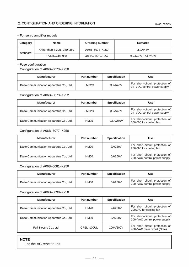
B–65162E/03
50
– For servo amplifier module
Category Name Ordering number Remarks
StandardOther than SVM1–240, 360 A06B–6073–K250 3.2A/48V
StandardSVM1–240, 360 A06B–6073–K252 3.2A/48V,0.5A/250V
– Fuse configuration
Configuration of A06B–6073–K250
Manufacturer Part number Specification Use
Daito Communication Apparatus Co., Ltd. LM32C 3.2A/48VFor short–circuit protection of24–VDC control power supply
Configuration of A06B–6073–K252
Manufacturer Part number Specification Use
Daito Communication Apparatus Co., Ltd. LM32C 3.2A/48VFor short–circuit protection of24–VDC control power supply
Daito Communication Apparatus Co., Ltd. HM05 0.5A/250VFor short–circuit protection of200VAC for cooling fan
Configuration of A06B–6077–K250
Manufacturer Part number Specification Use
Daito Communication Apparatus Co., Ltd. HM20 2A/250VFor short–circuit protection of200VAC for cooling fan
Daito Communication Apparatus Co., Ltd. HM50 5A/250VFor short–circuit protection of200–VAC control power supply
Configuration of A06B–6081–K250
Manufacturer Part number Specification Use
Daito Communication Apparatus Co., Ltd. HM50 5A/250VFor short–circuit protection of200–VAC control power supply
Configuration of A06B–6098–K250
Manufacturer Part number Specification Use
Daito Communication Apparatus Co., Ltd. HM20 2A/250VFor short–circuit protection of200VAC for cooling fan
Daito Communication Apparatus Co., Ltd. HM50 5A/250VFor short–circuit protection of200–VAC control power supply
Fuji Electric Co., Ltd. CR6L–100UL 100A/600VFor short–circuit protection of400–VAC main circuit (Note)
NOTEFor the AC reactor unit
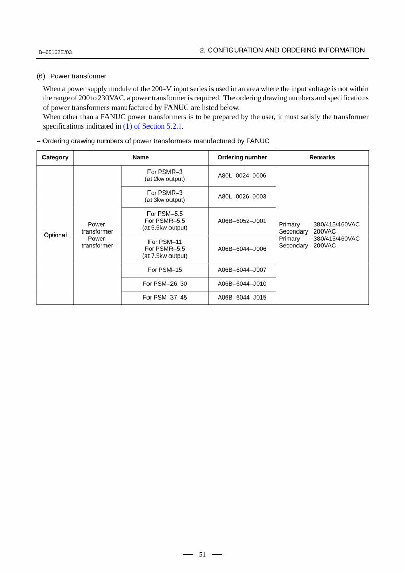
B–65162E/03
51
(6) Power transformer
When a power supply module of the 200–V input series is used in an area where the input voltage is not withinthe range of 200 to 230VAC, a power transformer is required. The ordering drawing numbers and specificationsof power transformers manufactured by FANUC are listed below.When other than a FANUC power transformers is to be prepared by the user, it must satisfy the transformerspecifications indicated in (1) of Section 5.2.1.
– Ordering drawing numbers of power transformers manufactured by FANUC
Category Name Ordering number Remarks
For PSMR–3(at 2kw output) A80L–0024–0006
For PSMR–3(at 3kw output) A80L–0026–0003
Optional
Power transformer
For PSM–5.5For PSMR–5.5
(at 5.5kw output)A06B–6052–J001
Primary 380/415/460VACSecondary 200VACOptional
Power transformer
For PSM–11For PSMR–5.5
(at 7.5kw output)A06B–6044–J006
yPrimary 380/415/460VACSecondary 200VAC
For PSM–15 A06B–6044–J007
For PSM–26, 30 A06B–6044–J010
For PSM–37, 45 A06B–6044–J015
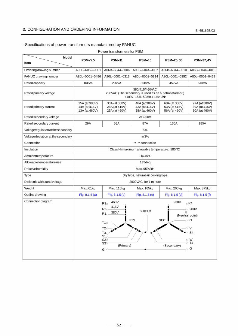
B–65162E/03
52
– Specifications of power transformers manufactured by FANUC
Power transformers for PSM
Model
ItemPSM–5.5 PSM–11 PSM–15 PSM–26, 30 PSM–37, 45
Ordering drawing number A06B–6052–J001 A06B–6044–J006 A06B–6044–J007 A06B–6044–J010 A06B–6044–J015
FANUC drawing number A80L–0001–0496 A80L–0001–0313 A80L–0001–0314 A80L–0001–0352 A80L–0001–0452
Rated capacity 10kVA 20kVA 30kVA 45kVA 64kVA
Rated primary voltage380/415/460VAC
230VAC (The secondary is used as an autotransformer.)+10% –15%, 50/601Hz, 3Φ
Rated primary current15A (at 380V)14A (at 415V)13A (at 460V)
30A (at 380V)28A (at 415V)25A (at 460V)
46A (at 380V)42A (at 415V)38A (at 460V)
68A (at 380V)63A (at 415V)56A (at 460V)
97A (at 380V)89A (at 415V)80A (at 460V)
Rated secondary voltage AC200V
Rated secondary current 29A 58A 87A 130A 185A
Voltage regulation at the secondary 5%
Voltage deviation at the secondary 3%
Connection Y–Y connection
Insulation Class H (maximum allowable temperature: 180°C)
Ambient temperature 0 to 45°C
Allowable temperature rise 135deg
Relative humidity Max. 95%RH
Type Dry type, natural air cooling type
Dielectric withstand voltage 2000VAC, for 1 minute
Weight Max. 61kg Max. 115kg Max. 165kg Max. 260kg Max. 375kg
Outline drawing Fig. 8.1.5 (a) Fig. 8.1.5 (b) Fig. 8.1.5 (c) Fig. 8.1.5 (d) Fig. 8.1.5 (f)
Connection diagramR3
R2R1
460V
415V
380V
T1
T2T3S1S2S3
G
PRI.
SHIELD
SEC.
230V R4
200VU
O
VS4
WT4
G
(Primary) (Secondary)
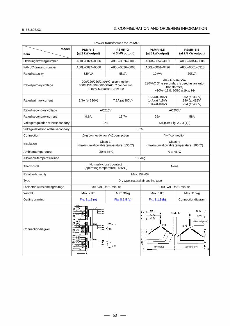
B–65162E/03
53
Power transformer for PSMR
Model
ItemPSMR–3
(at 2 kW output)PSMR–3
(at 3 kW output)PSMR–5.5
(at 5 kW output)PSMR–5.5
(at 7.5 kW output)
Ordering drawing number A80L–0024–0006 A80L–0026–0003 A06B–6052–J001 A06B–6044–J006
FANUC drawing number A80L–0024–0006 A80L–0026–0003 A80L–0001–0496 A80L–0001–0313
Rated capacity 3.5kVA 5kVA 10kVA 20kVA
Rated primary voltage200/220/230/240VAC, ∆ connection
380/415/460/480/550VAC, Y connection15%, 50/60Hz2Hz; 3Φ
380/415/460VAC230VAC (The secondary is used as an auto-
transformer.)+10% –15%, 50/601Hz, 3Φ
Rated primary current 5.3A (at 380V) 7.6A (at 380V)15A (at 380V)14A (at 415V)13A (at 460V)
30A (at 380V)28A (at 415V)25A (at 460V)
Rated secondary voltage AC210V AC200V
Rated secondary current 9.6A 13.7A 29A 58A
Voltage regulation at the secondary 2% 5% (See Fig. 2.2.3 (1).)
Voltage deviation at the secondary 3%
Connection ∆–∆ connection or Y–∆ connection Y–Y connection
InsulationClass B
(maximum allowable temperature: 130°C)Class H
(maximum allowable temperature: 180°C)
Ambient temperature –20 to 55°C 0 to 45°C
Allowable temperature rise 135deg
ThermostatNormally closed contact
(operating temperature: 135°C) None
Relative humidity Max. 95%RH
Type Dry type, natural air cooling type
Dielectric withstanding voltage 2300VAC, for 1 minute 2000VAC, for 1 minute
Weight Max. 27kg Max. 36kg Max. 61kg Max. 115kg
Outline drawing Fig. 8.1.5 (e) Fig. 8.1.5 (a) Fig. 8.1.5 (b) Connection diagram
Connection diagram
(Primary) (Secondary)
(Neutral point)
200V
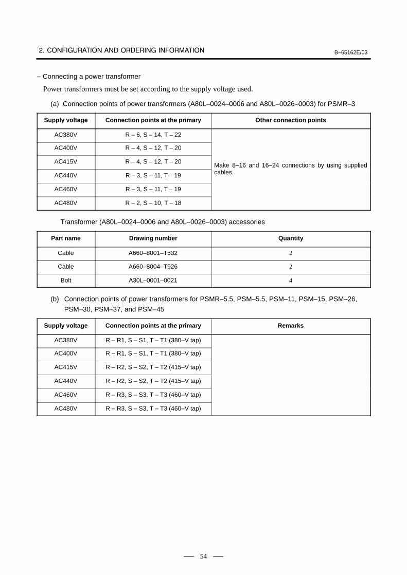
B–65162E/03
54
– Connecting a power transformer
Power transformers must be set according to the supply voltage used.
(a) Connection points of power transformers (A80L–0024–0006 and A80L–0026–0003) for PSMR–3
Supply voltage Connection points at the primary Other connection points
AC380V R – 6, S – 14, T – 22
AC400V R – 4, S – 12, T – 20
AC415V R – 4, S – 12, T – 20Make 8–16 and 16–24 connections by using supplied
AC440V R – 3, S – 11, T – 19
Make 8 16 and 16 24 connections by using su liedcables.
AC460V R – 3, S – 11, T – 19
AC480V R – 2, S – 10, T – 18
Transformer (A80L–0024–0006 and A80L–0026–0003) accessories
Part name Drawing number Quantity
Cable A660–8001–T532 2
Cable A660–8004–T926 2
Bolt A30L–0001–0021 4
(b) Connection points of power transformers for PSMR–5.5, PSM–5.5, PSM–11, PSM–15, PSM–26,
PSM–30, PSM–37, and PSM–45
Supply voltage Connection points at the primary Remarks
AC380V R – R1, S – S1, T – T1 (380–V tap)
AC400V R – R1, S – S1, T – T1 (380–V tap)
AC415V R – R2, S – S2, T – T2 (415–V tap)
AC440V R – R2, S – S2, T – T2 (415–V tap)
AC460V R – R3, S – S3, T – T3 (460–V tap)
AC480V R – R3, S – S3, T – T3 (460–V tap)
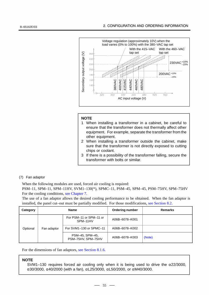
B–65162E/03
55
Voltage regulation (approximately 10V) when theload varies (0% to 100%) with the 380–VAC tap set
With the 415–VAC tap set
AC input voltage (V)
230VAC+10%–15%
200VAC +10%
–15%
380V
AC
400V
AC
415V
AC
440V
AC
480V
AC
460V
AC
Sec
onda
ry o
utpu
t vol
tage
(V
)
With the 460–VAC tap set
NOTE1 When installing a transformer in a cabinet, be careful to
ensure that the transformer does not thermally affect otherequipment. For example, separate the transformer from theother equipment.
2 When installing a transformer outside the cabinet, makesure that the transformer is not directly exposed to cuttingchips or coolant.
3 If there is a possibility of the transformer falling, secure thetransformer with bolts or similar.
(7) Fan adaptor
When the following modules are used, forced air cooling is required:PSM–11, SPM–11, SPM–11HV, SVM1–130(*), SPMC–11, PSM–45, SPM–45, PSM–75HV, SPM–75HVFor the cooling conditions, see Chapter 7.The use of a fan adaptor allows the desired cooling performance to be obtained. When the fan adaptor isinstalled, the panel cut–out must be partially modified. For those modifications, see Section 8.2.
Category Name Ordering number Remarks
For PSM–11 or SPM–11 orSPM–11HV A06B–6078–K001
Optional Fan adaptor For SVM1–130 or SPMC–11 A06B–6078–K002
PSM–45, SPM–45,PSM–75HV, SPM–75HV A06B–6078–K003 (Note)
For the dimensions of fan adaptors, see Section 8.1.6.
NOTESVM1–130 requires forced air cooling only when it is being used to drive the α22/3000,α30/3000, α40/2000 (with a fan), αL25/3000, αL50/2000, or αM40/3000.
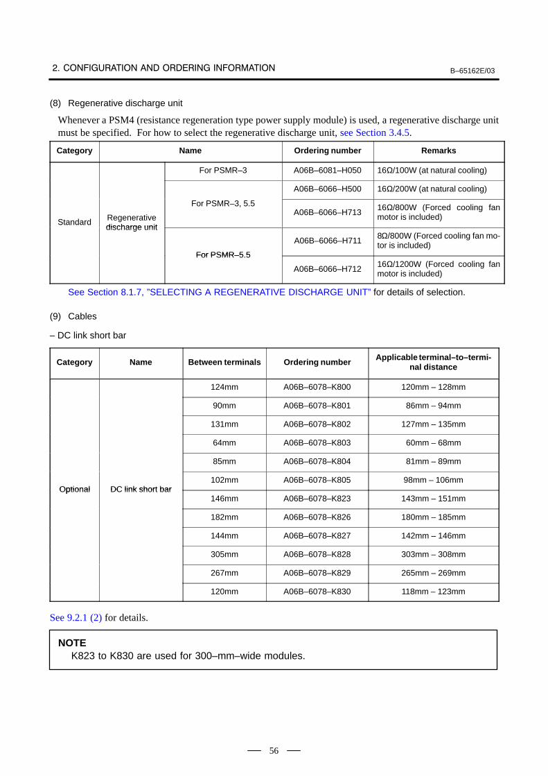
B–65162E/03
56
(8) Regenerative discharge unit
Whenever a PSM4 (resistance regeneration type power supply module) is used, a regenerative discharge unitmust be specified. For how to select the regenerative discharge unit, see Section 3.4.5.
Category Name Ordering number Remarks
For PSMR–3 A06B–6081–H050 16Ω/100W (at natural cooling)
A06B–6066–H500 16Ω/200W (at natural cooling)
Standard Regenerativedischarge unit
For PSMR–3, 5.5A06B–6066–H713
16Ω/800W (Forced cooling fanmotor is included)
Standarddischarge unit
For PSMR–5 5
A06B–6066–H7118Ω/800W (Forced cooling fan mo-tor is included)
For PSMR–5.5
A06B–6066–H71216Ω/1200W (Forced cooling fanmotor is included)
See Section 8.1.7, ”SELECTING A REGENERATIVE DISCHARGE UNIT” for details of selection.
(9) Cables
– DC link short bar
Category Name Between terminals Ordering number Applicable terminal–to–termi-nal distance
124mm A06B–6078–K800 120mm – 128mm
90mm A06B–6078–K801 86mm – 94mm
131mm A06B–6078–K802 127mm – 135mm
64mm A06B–6078–K803 60mm – 68mm
85mm A06B–6078–K804 81mm – 89mm
Optional DC link short bar102mm A06B–6078–K805 98mm – 106mm
Optional DC link short bar146mm A06B–6078–K823 143mm – 151mm
182mm A06B–6078–K826 180mm – 185mm
144mm A06B–6078–K827 142mm – 146mm
305mm A06B–6078–K828 303mm – 308mm
267mm A06B–6078–K829 265mm – 269mm
120mm A06B–6078–K830 118mm – 123mm
See 9.2.1 (2) for details.
NOTEK823 to K830 are used for 300–mm–wide modules.
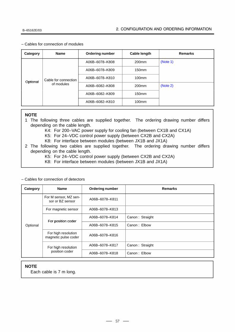
B–65162E/03
57
– Cables for connection of modules
Category Name Ordering number Cable length Remarks
A06B–6078–K808 200mm (Note 1)
A06B–6078–K809 150mm
Optional Cable for connectionA06B–6078–K810 100mm
Optional Cable for connectionof modules A06B–6082–K808 200mm (Note 2)
A06B–6082–K809 150mm
A06B–6082–K810 100mm
NOTE1 The following three cables are supplied together. The ordering drawing number differs
depending on the cable length.K4: For 200–VAC power supply for cooling fan (between CX1B and CX1A)K5: For 24–VDC control power supply (between CX2B and CX2A)K8: For interface between modules (between JX1B and JX1A)
2 The following two cables are supplied together. The ordering drawing number differsdepending on the cable length.
K5: For 24–VDC control power supply (between CX2B and CX2A)K8: For interface between modules (between JX1B and JX1A)
– Cables for connection of detectors
Category Name Ordering number Remarks
For M sensor, MZ sen-sor or BZ sensor A06B–6078–K811
For magnetic sensor A06B–6078–K813
For position coderA06B–6078–K814 Canon : Straight
OptionalFor position coder
A06B–6078–K815 Canon : Elbow
For high resolutionmagnetic pulse coder A06B–6078–K816
For high resolutionA06B–6078–K817 Canon : Straight
For high resolutionposition coder A06B–6078–K818 Canon : Elbow
NOTEEach cable is 7 m long.
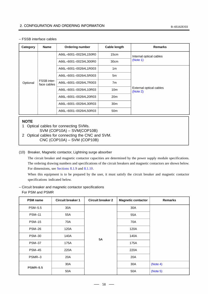
B–65162E/03
58
– FSSB interface cables
Category Name Ordering number Cable length Remarks
A66L–6001–0023#L150R0 15cmInternal optical cables
A66L–6001–0023#L300R0 30cm
Internal o tical cables (Note 1)
A66L–6001–0026#L1R003 1m
A66L–6001–0026#L5R003 5m
OptionalFSSB inter-face cables A66L–6001–0026#L7R003 7m
A66L–6001–0026#L10R03 10mExternal optical cables (Note 2)
A66L–6001–0026#L20R03 20m
( )
A66L–6001–0026#L30R03 30m
A66L–6001–0026#L50R03 50m
NOTE1 Optical cables for connecting SVMs.
SVM (COP10A) – SVM(COP10B)2 Optical cables for connecting the CNC and SVM.
CNC (COP10A) – SVM (COP10B)
(10) Breaker, Magnetic contactor, Lightning surge absorber
The circuit breaker and magnetic contactor capacities are determined by the power supply module specifications.
The ordering drawing numbers and specifications of the circuit breakers and magnetic contactors are shown below.
For dimensions, see Sections 8.1.9 and 8.1.10.
When this equipment is to be prepared by the user, it must satisfy the circuit breaker and magnetic contactor
specifications indicated below.
– Circuit breaker and magnetic contactor specifications
For PSM and PSMR
PSM name Circuit breaker 1 Circuit breaker 2 Magnetic contactor Remarks
PSM–5.5 30A 30A
PSM–11 55A 55A
PSM–15 70A 70A
PSM–26 120A 120A
PSM–30 140A5A
140A
PSM–37 175A5A
175A
PSM–45 220A 220A
PSMR–3 20A 20A
PSMR–5 530A 30A (Note 4)
PSMR–5.550A 50A (Note 5)
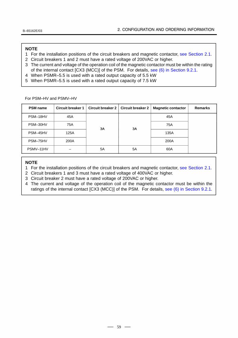
B–65162E/03
59
NOTE1 For the installation positions of the circuit breakers and magnetic contactor, see Section 2.1.2 Circuit breakers 1 and 2 must have a rated voltage of 200VAC or higher.3 The current and voltage of the operation coil of the magnetic contactor must be within the rating
of the internal contact [CX3 (MCC)] of the PSM. For details, see (6) in Section 9.2.1.4 When PSMR–5.5 is used with a rated output capacity of 5.5 kW5 When PSMR–5.5 is used with a rated output capacity of 7.5 kW
For PSM–HV and PSMV–HV
PSM name Circuit breaker 1 Circuit breaker 2 Circuit breaker 2 Magnetic contactor Remarks
PSM–18HV 45A 45A
PSM–30HV 75A3A 3A
75A
PSM–45HV 125A3A 3A
135A
PSM–75HV 200A 200A
PSMV–11HV – 5A 5A 60A
NOTE1 For the installation positions of the circuit breakers and magnetic contactor, see Section 2.1.2 Circuit breakers 1 and 3 must have a rated voltage of 400VAC or higher.3 Circuit breaker 2 must have a rated voltage of 200VAC or higher.4 The current and voltage of the operation coil of the magnetic contactor must be within the
ratings of the internal contact [CX3 (MCC)] of the PSM. For details, see (6) in Section 9.2.1.
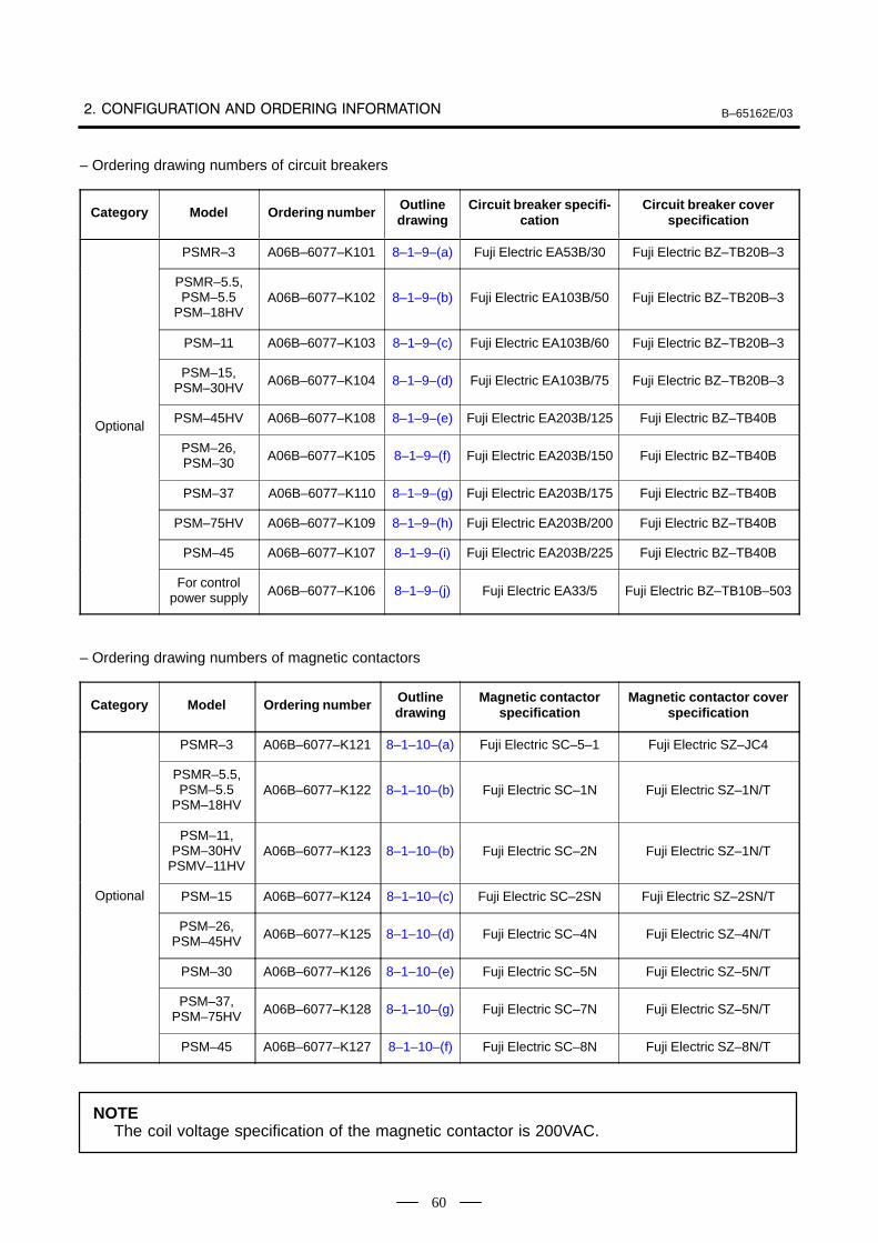
B–65162E/03
60
– Ordering drawing numbers of circuit breakers
Category Model Ordering number Outlinedrawing
Circuit breaker specifi-cation
Circuit breaker coverspecification
PSMR–3 A06B–6077–K101 8–1–9–(a) Fuji Electric EA53B/30 Fuji Electric BZ–TB20B–3
PSMR–5.5,PSM–5.5
PSM–18HVA06B–6077–K102 8–1–9–(b) Fuji Electric EA103B/50 Fuji Electric BZ–TB20B–3
PSM–11 A06B–6077–K103 8–1–9–(c) Fuji Electric EA103B/60 Fuji Electric BZ–TB20B–3
PSM–15,PSM–30HV A06B–6077–K104 8–1–9–(d) Fuji Electric EA103B/75 Fuji Electric BZ–TB20B–3
OptionalPSM–45HV A06B–6077–K108 8–1–9–(e) Fuji Electric EA203B/125 Fuji Electric BZ–TB40B
O tional
PSM–26,PSM–30 A06B–6077–K105 8–1–9–(f) Fuji Electric EA203B/150 Fuji Electric BZ–TB40B
PSM–37 A06B–6077–K110 8–1–9–(g) Fuji Electric EA203B/175 Fuji Electric BZ–TB40B
PSM–75HV A06B–6077–K109 8–1–9–(h) Fuji Electric EA203B/200 Fuji Electric BZ–TB40B
PSM–45 A06B–6077–K107 8–1–9–(i) Fuji Electric EA203B/225 Fuji Electric BZ–TB40B
For controlpower supply A06B–6077–K106 8–1–9–(j) Fuji Electric EA33/5 Fuji Electric BZ–TB10B–503
– Ordering drawing numbers of magnetic contactors
Category Model Ordering number Outlinedrawing
Magnetic contactorspecification
Magnetic contactor coverspecification
PSMR–3 A06B–6077–K121 8–1–10–(a) Fuji Electric SC–5–1 Fuji Electric SZ–JC4
PSMR–5.5,PSM–5.5
PSM–18HVA06B–6077–K122 8–1–10–(b) Fuji Electric SC–1N Fuji Electric SZ–1N/T
PSM–11,PSM–30HV
PSMV–11HVA06B–6077–K123 8–1–10–(b) Fuji Electric SC–2N Fuji Electric SZ–1N/T
Optional PSM–15 A06B–6077–K124 8–1–10–(c) Fuji Electric SC–2SN Fuji Electric SZ–2SN/T
PSM–26,PSM–45HV A06B–6077–K125 8–1–10–(d) Fuji Electric SC–4N Fuji Electric SZ–4N/T
PSM–30 A06B–6077–K126 8–1–10–(e) Fuji Electric SC–5N Fuji Electric SZ–5N/T
PSM–37,PSM–75HV A06B–6077–K128 8–1–10–(g) Fuji Electric SC–7N Fuji Electric SZ–5N/T
PSM–45 A06B–6077–K127 8–1–10–(f) Fuji Electric SC–8N Fuji Electric SZ–8N/T
NOTEThe coil voltage specification of the magnetic contactor is 200VAC.
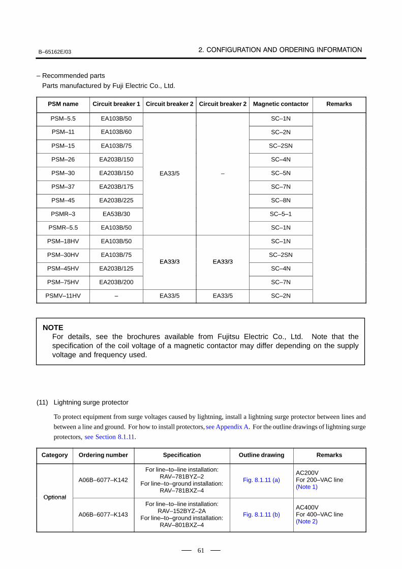
B–65162E/03
61
– Recommended parts
Parts manufactured by Fuji Electric Co., Ltd.
PSM name Circuit breaker 1 Circuit breaker 2 Circuit breaker 2 Magnetic contactor Remarks
PSM–5.5 EA103B/50 SC–1N
PSM–11 EA103B/60 SC–2N
PSM–15 EA103B/75 SC–2SN
PSM–26 EA203B/150 SC–4N
PSM–30 EA203B/150 EA33/5 – SC–5N
PSM–37 EA203B/175 SC–7N
PSM–45 EA203B/225 SC–8N
PSMR–3 EA53B/30 SC–5–1
PSMR–5.5 EA103B/50 SC–1N
PSM–18HV EA103B/50 SC–1N
PSM–30HV EA103B/75EA33/3 EA33/3
SC–2SN
PSM–45HV EA203B/125EA33/3 EA33/3
SC–4N
PSM–75HV EA203B/200 SC–7N
PSMV–11HV – EA33/5 EA33/5 SC–2N
NOTEFor details, see the brochures available from Fujitsu Electric Co., Ltd. Note that thespecification of the coil voltage of a magnetic contactor may differ depending on the supplyvoltage and frequency used.
(11) Lightning surge protector
To protect equipment from surge voltages caused by lightning, install a lightning surge protector between lines and
between a line and ground. For how to install protectors, see Appendix A. For the outline drawings of lightning surge
protectors, see Section 8.1.11.
Category Ordering number Specification Outline drawing Remarks
Optional
A06B–6077–K142
For line–to–line installation:RAV–781BYZ–2
For line–to–ground installation:RAV–781BXZ–4
Fig. 8.1.11 (a)AC200VFor 200–VAC line(Note 1)
Optional
A06B–6077–K143
For line–to–line installation:RAV–152BYZ–2A
For line–to–ground installation:RAV–801BXZ–4
Fig. 8.1.11 (b)AC400VFor 400–VAC line(Note 2)
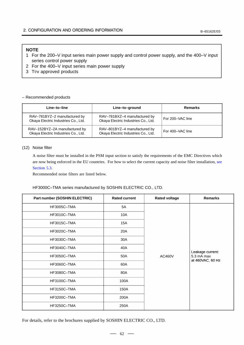
B–65162E/03
62
NOTE1 For the 200–V input series main power supply and control power supply, and the 400–V input
series control power supply2 For the 400–V input series main power supply3 Tv approved products
– Recommended products
Line–to–line Line–to–ground Remarks
RAV–781BYZ–2 manufactured byOkaya Electric Industries Co., Ltd.
RAV–781BXZ–4 manufactured byOkaya Electric Industries Co., Ltd. For 200–VAC line
RAV–152BYZ–2A manufactured byOkaya Electric Industries Co., Ltd.
RAV–801BYZ–4 manufactured byOkaya Electric Industries Co., Ltd. For 400–VAC line
(12) Noise filter
A noise filter must be installed in the PSM input section to satisfy the requirements of the EMC Directives which
are now being enforced in the EU countries. For how to select the current capacity and noise filter installation, see
Section 5.3.
Recommended noise filters are listed below.
HF3000C–TMA series manufactured by SOSHIN ELECTRIC CO., LTD.
Part number (SOSHIN ELECTRIC) Rated current Rated voltage Remarks
HF3005C–TMA 5A
HF3010C–TMA 10A
HF3015C–TMA 15A
HF3020C–TMA 20A
HF3030C–TMA 30A
HF3040C–TMA 40ALeakage current:
HF3050C–TMA 50A AC460VLeakage current: 5.3 mA max at 460VAC 60 Hz
HF3060C–TMA 60Aat 460VAC, 60 Hz
HF3080C–TMA 80A
HF3100C–TMA 100A
HF3150C–TMA 150A
HF3200C–TMA 200A
HF3250C–TMA 250A
For details, refer to the brochures supplied by SOSHIN ELECTRIC CO., LTD.
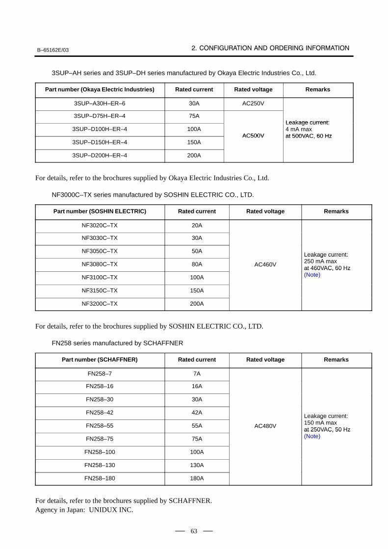
B–65162E/03
63
3SUP–AH series and 3SUP–DH series manufactured by Okaya Electric Industries Co., Ltd.
Part number (Okaya Electric Industries) Rated current Rated voltage Remarks
3SUP–A30H–ER–6 30A AC250V
3SUP–D75H–ER–4 75ALeakage current:
3SUP–D100H–ER–4 100AAC500V
Leakage current: 4 mA max at 500VAC 60 Hz
3SUP–D150H–ER–4 150AAC500V at 500VAC, 60 Hz
3SUP–D200H–ER–4 200A
For details, refer to the brochures supplied by Okaya Electric Industries Co., Ltd.
NF3000C–TX series manufactured by SOSHIN ELECTRIC CO., LTD.
Part number (SOSHIN ELECTRIC) Rated current Rated voltage Remarks
NF3020C–TX 20A
NF3030C–TX 30A
NF3050C–TX 50ALeakage current:
NF3080C–TX 80A AC460V
Leakage current: 250 mA max at 460VAC, 60 Hz
NF3100C–TX 100A
at 460VAC, 60 Hz (Note)
NF3150C–TX 150A
NF3200C–TX 200A
For details, refer to the brochures supplied by SOSHIN ELECTRIC CO., LTD.
FN258 series manufactured by SCHAFFNER
Part number (SCHAFFNER) Rated current Rated voltage Remarks
FN258–7 7A
FN258–16 16A
FN258–30 30A
FN258–42 42ALeakage current:
FN258–55 55A AC480V
Leakage current: 150 mA max at 250VAC, 50 Hz
FN258–75 75A
at 250VAC, 50 Hz (Note)
FN258–100 100A
FN258–130 130A
FN258–180 180A
For details, refer to the brochures supplied by SCHAFFNER. Agency in Japan: UNIDUX INC.
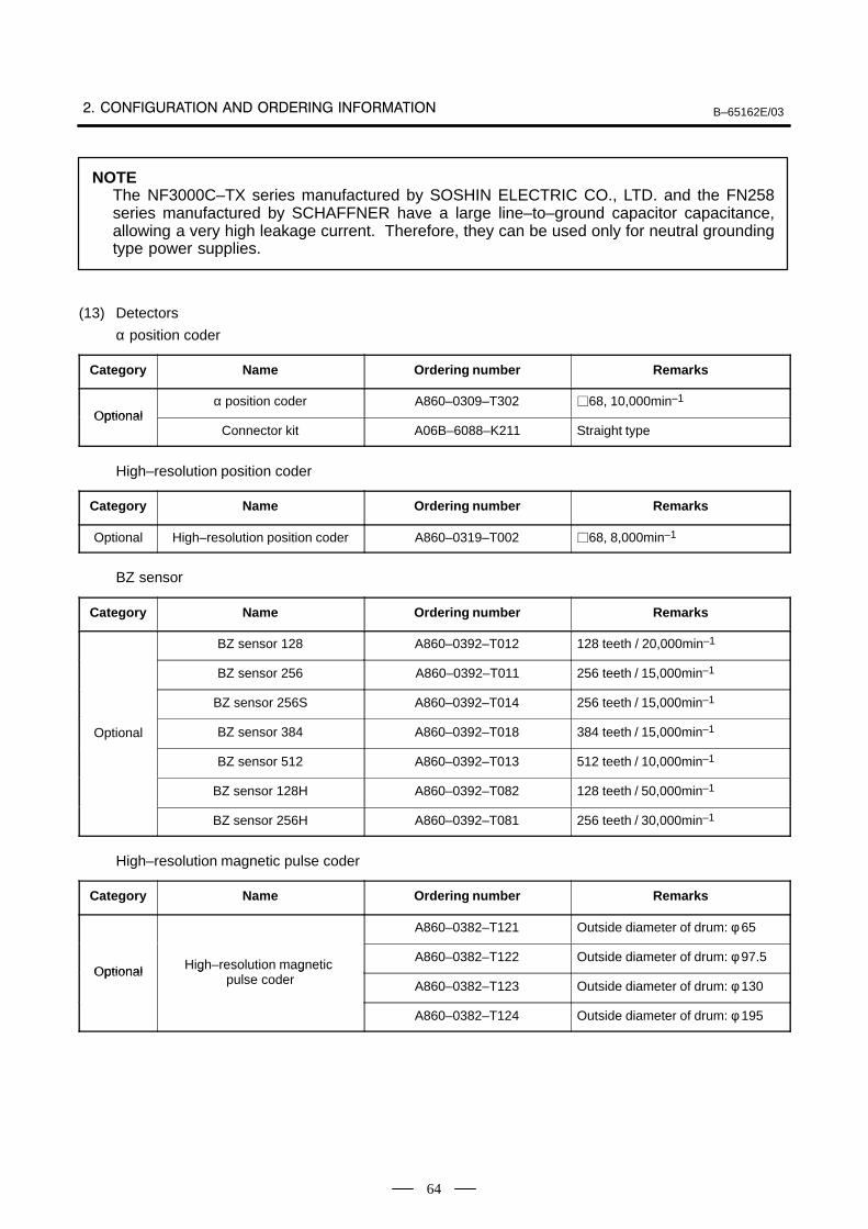
B–65162E/03
64
NOTEThe NF3000C–TX series manufactured by SOSHIN ELECTRIC CO., LTD. and the FN258series manufactured by SCHAFFNER have a large line–to–ground capacitor capacitance,allowing a very high leakage current. Therefore, they can be used only for neutral groundingtype power supplies.
(13) Detectors
α position coder
Category Name Ordering number Remarks
Optionalα position coder A860–0309–T302 68, 10,000min–1
OptionalConnector kit A06B–6088–K211 Straight type
High–resolution position coder
Category Name Ordering number Remarks
Optional High–resolution position coder A860–0319–T002 68, 8,000min–1
BZ sensor
Category Name Ordering number Remarks
BZ sensor 128 A860–0392–T012 128 teeth / 20,000min–1
BZ sensor 256 A860–0392–T011 256 teeth / 15,000min–1
BZ sensor 256S A860–0392–T014 256 teeth / 15,000min–1
Optional BZ sensor 384 A860–0392–T018 384 teeth / 15,000min–1
BZ sensor 512 A860–0392–T013 512 teeth / 10,000min–1
BZ sensor 128H A860–0392–T082 128 teeth / 50,000min–1
BZ sensor 256H A860–0392–T081 256 teeth / 30,000min–1
High–resolution magnetic pulse coder
Category Name Ordering number Remarks
A860–0382–T121 Outside diameter of drum: φ 65
Optional High–resolution magnetic A860–0382–T122 Outside diameter of drum: φ 97.5
Optional High resolution magnetic pulse coder A860–0382–T123 Outside diameter of drum: φ 130
A860–0382–T124 Outside diameter of drum: φ 195
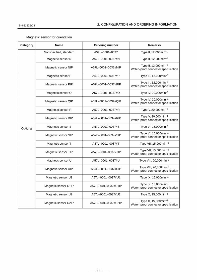
B–65162E/03
65
Magnetic sensor for orientation
Category Name Ordering number Remarks
Not specified, standard A57L–0001–0037 Type II, 12,000min–1
Magnetic sensor N A57L–0001–0037#N Type II, 12,000min–1
Magnetic sensor NIP A57L–0001–0037#NIPType II, 12,000min–1
Water–proof connector specification
Magnetic sensor P A57L–0001–0037#P Type III, 12,000min–1
Magnetic sensor PIP A57L–0001–0037#PIPType III, 12,000min–1
Water–proof connector specification
Magnetic sensor Q A57L–0001–0037#Q Type IV, 20,000min–1
Magnetic sensor QIP A57L–0001–0037#QIPType IV, 20,000min–1
Water–proof connector specification
Magnetic sensor R A57L–0001–0037#R Type V, 20,000min–1
Magnetic sensor RIP A57L–0001–0037#RIPType V, 20,000min–1
Water–proof connector specification
OptionalMagnetic sensor S A57L–0001–0037#S Type VI, 15,000min–1
O tional
Magnetic sensor SIP A57L–0001–0037#SIPType VI, 15,000min–1
Water–proof connector specification
Magnetic sensor T A57L–0001–0037#T Type VII, 15,000min–1
Magnetic sensor TIP A57L–0001–0037#TIPType VII, 15,000min–1
Water–proof connector specification
Magnetic sensor U A57L–0001–0037#U Type VIII, 20,000min–1
Magnetic sensor UIP A57L–0001–0037#UIPType VIII, 20,000min–1
Water–proof connector specification
Magnetic sensor U1 A57L–0001–0037#U1 Type IX, 15,000min–1
Magnetic sensor U1IP A57L–0001–0037#U1IPType IX, 15,000min–1
Water–proof connector specification
Magnetic sensor U2 A57L–0001–0037#U2 Type X, 15,000min–1
Magnetic sensor U2IP A57L–0001–0037#U2IPType X, 15,000min–1
Water–proof connector specification
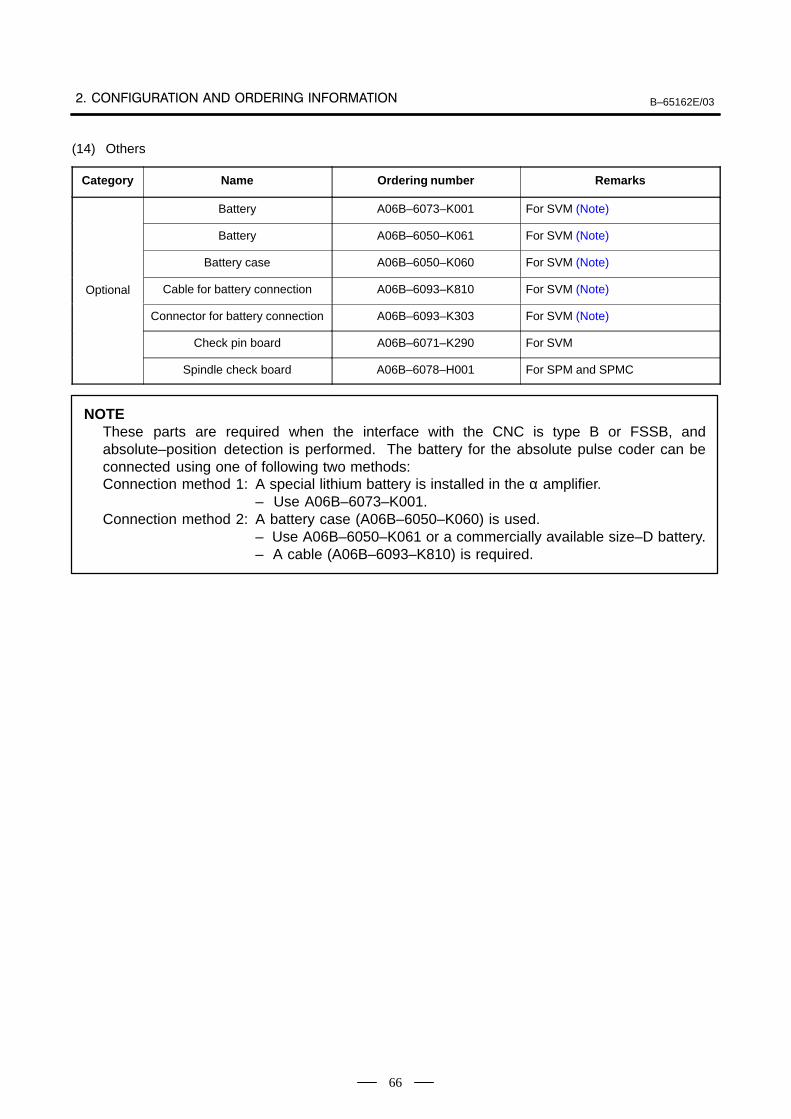
B–65162E/03
66
(14) Others
Category Name Ordering number Remarks
Battery A06B–6073–K001 For SVM (Note)
Battery A06B–6050–K061 For SVM (Note)
Battery case A06B–6050–K060 For SVM (Note)
Optional Cable for battery connection A06B–6093–K810 For SVM (Note)
Connector for battery connection A06B–6093–K303 For SVM (Note)
Check pin board A06B–6071–K290 For SVM
Spindle check board A06B–6078–H001 For SPM and SPMC
NOTEThese parts are required when the interface with the CNC is type B or FSSB, andabsolute–position detection is performed. The battery for the absolute pulse coder can beconnected using one of following two methods:Connection method 1: A special lithium battery is installed in the α amplifier.
– Use A06B–6073–K001.Connection method 2: A battery case (A06B–6050–K060) is used.
– Use A06B–6050–K061 or a commercially available size–D battery.– A cable (A06B–6093–K810) is required.

B–65162E/03
67
3
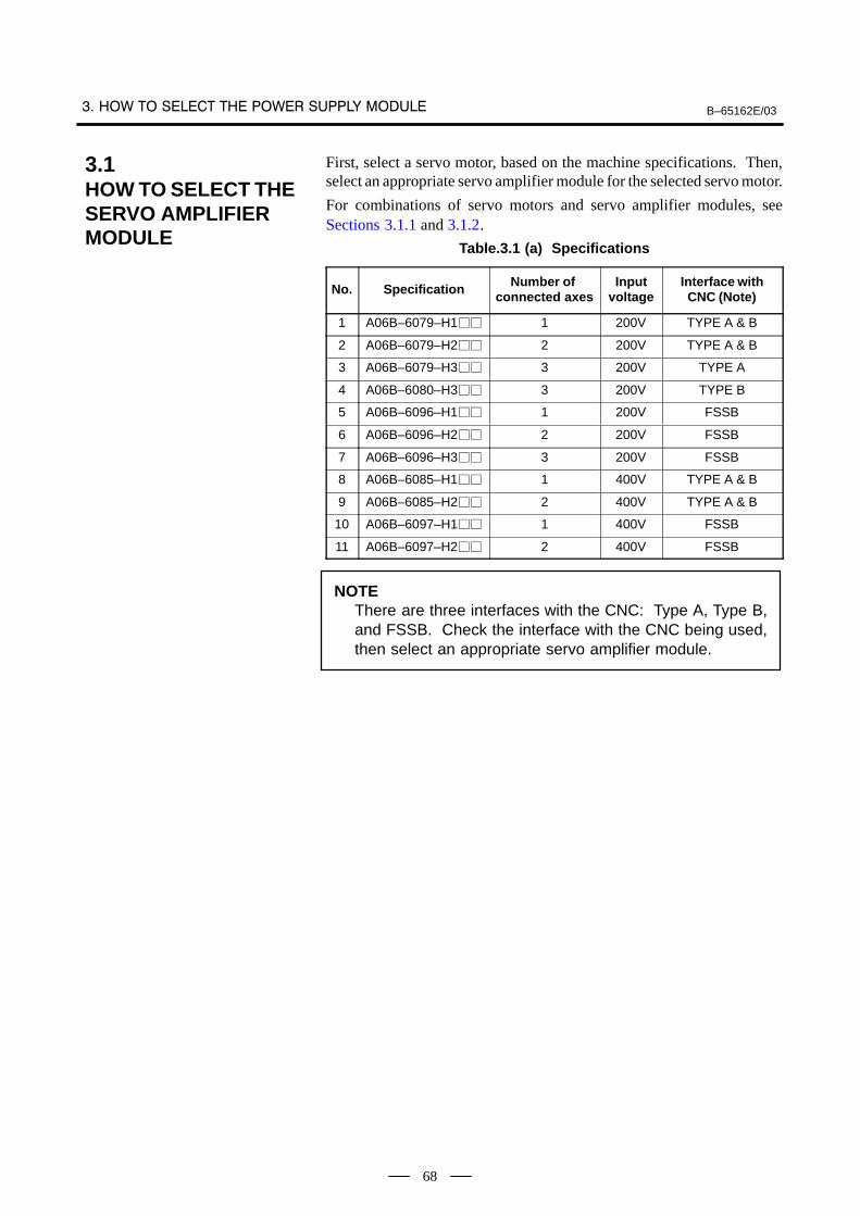
B–65162E/03
68
First, select a servo motor, based on the machine specifications. Then,select an appropriate servo amplifier module for the selected servo motor.
For combinations of servo motors and servo amplifier modules, seeSections 3.1.1 and 3.1.2.
Table.3.1 (a) Specifications
No. Specification Number of connected axes
Inputvoltage
Interface withCNC (Note)
1 A06B–6079–H1 1 200V TYPE A & B
2 A06B–6079–H2 2 200V TYPE A & B
3 A06B–6079–H3 3 200V TYPE A
4 A06B–6080–H3 3 200V TYPE B
5 A06B–6096–H1 1 200V FSSB
6 A06B–6096–H2 2 200V FSSB
7 A06B–6096–H3 3 200V FSSB
8 A06B–6085–H1 1 400V TYPE A & B
9 A06B–6085–H2 2 400V TYPE A & B
10 A06B–6097–H1 1 400V FSSB
11 A06B–6097–H2 2 400V FSSB
NOTEThere are three interfaces with the CNC: Type A, Type B,and FSSB. Check the interface with the CNC being used,then select an appropriate servo amplifier module.
3.1HOW TO SELECT THESERVO AMPLIFIER MODULE
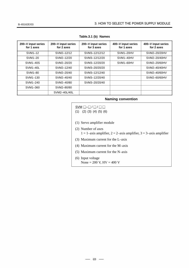
B–65162E/03
69
Table.3.1 (b) Names
200–V input series for 1 axes
200–V input series for 2 axes
200–V input series for 3 axes
400–V input series for 1 axes
400–V input series for 2 axes
SVM1–12 SVM2–12/12 SVM3–12/12/12 SVM1–20HV SVM2–20/20HV
SVM1–20 SVM2–12/20 SVM3–12/12/20 SVM1–40HV SVM2–20/40HV
SVM1–40S SVM2–20/20 SVM3–12/20/20 SVM1–60HV SVM2–20/60HV
SVM1–40L SVM2–12/40 SVM3–20/20/20 SVM2–40/40HV
SVM1–80 SVM2–20/40 SVM3–12/12/40 SVM2–40/60HV
SVM1–130 SVM2–40/40 SVM3–12/20/40 SVM2–60/60HV
SVM1–240 SVM2–40/80 SVM3–20/20/40
SVM1–360 SVM2–80/80
SVM2–40L/40L
Naming convention
SVM – / /
(1) (2) (3) (4)
(1) Servo amplifier module
(2) Number of axes1 = 1–axis amplifier, 2 = 2–axis amplifier, 3 = 3–axis amplifier
(3) Maximum current for the L–axis
(4) Maximum current for the M–axis
(5) Maximum current for the N–axis
(6) Input voltageNone = 200 V, HV = 400 V
(5) (6)
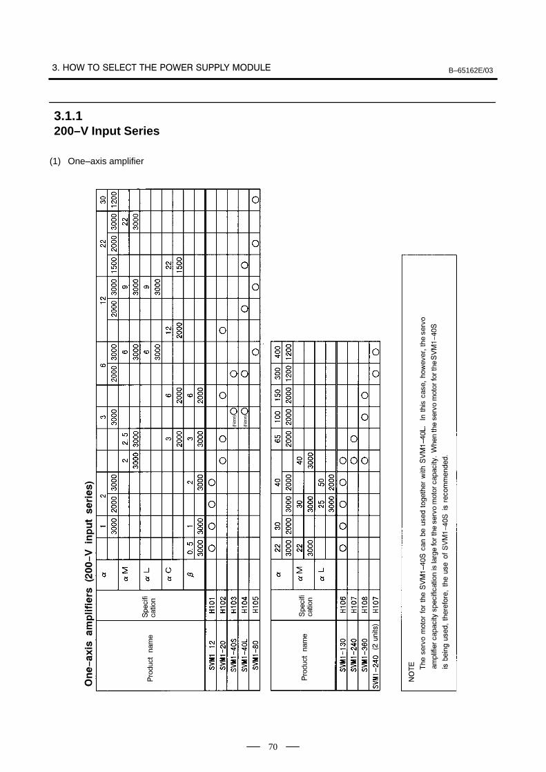
B–65162E/03
70
(1) One–axis amplifier
3.1.1200–V Input Series
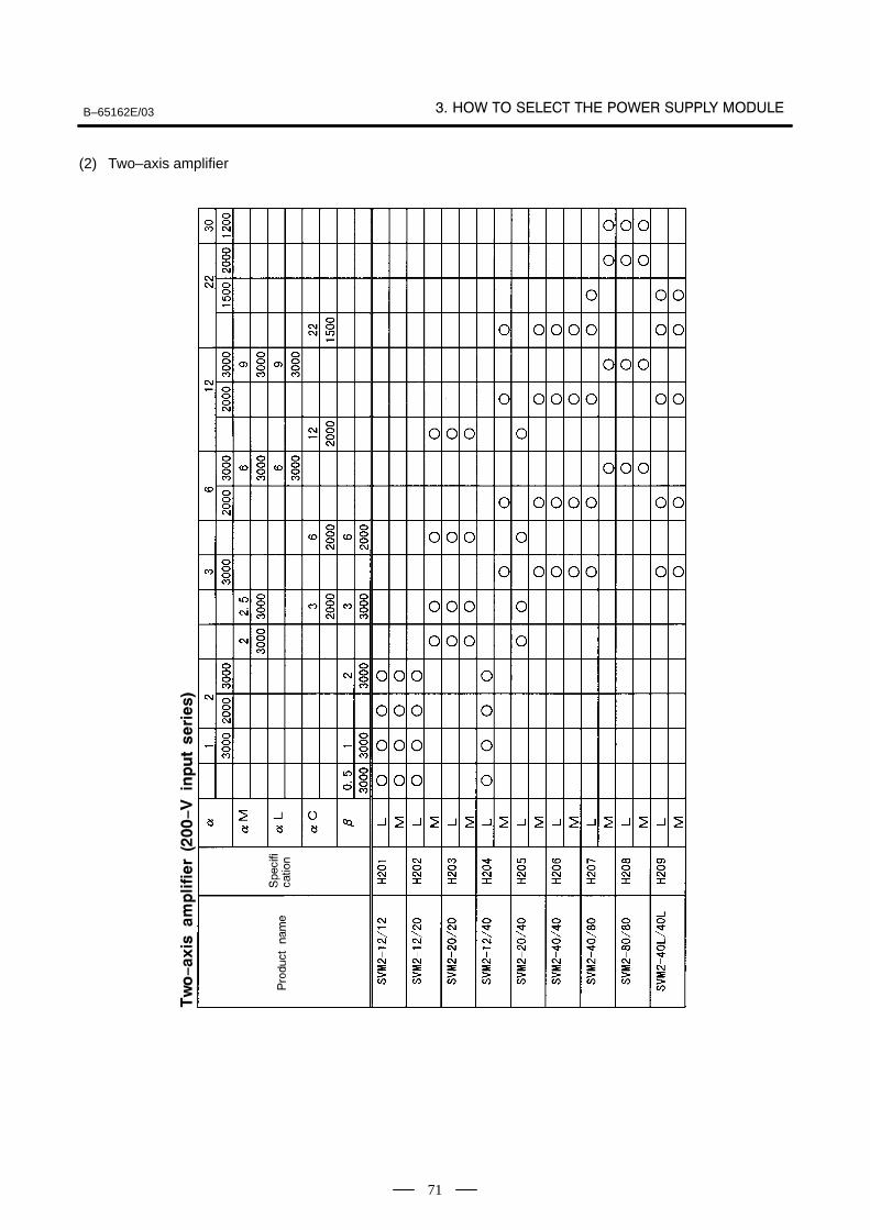
B–65162E/03
71
(2) Two–axis amplifier
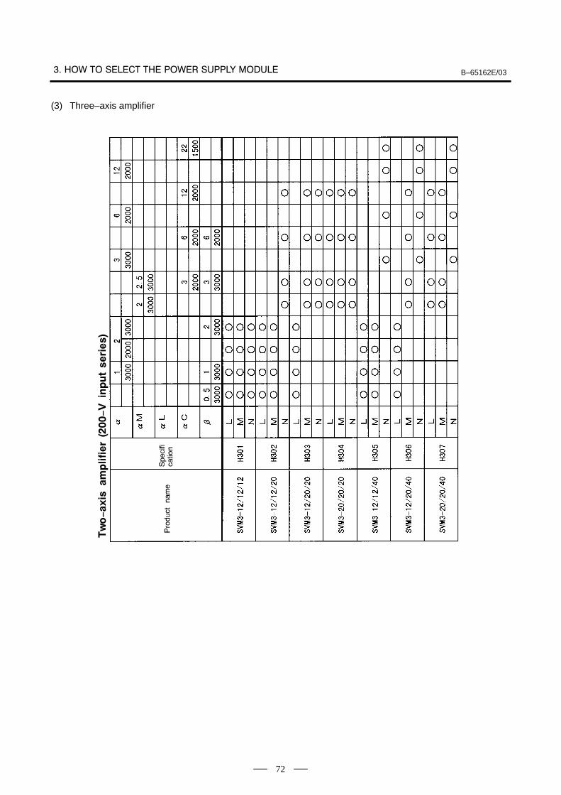
B–65162E/03
72
(3) Three–axis amplifier
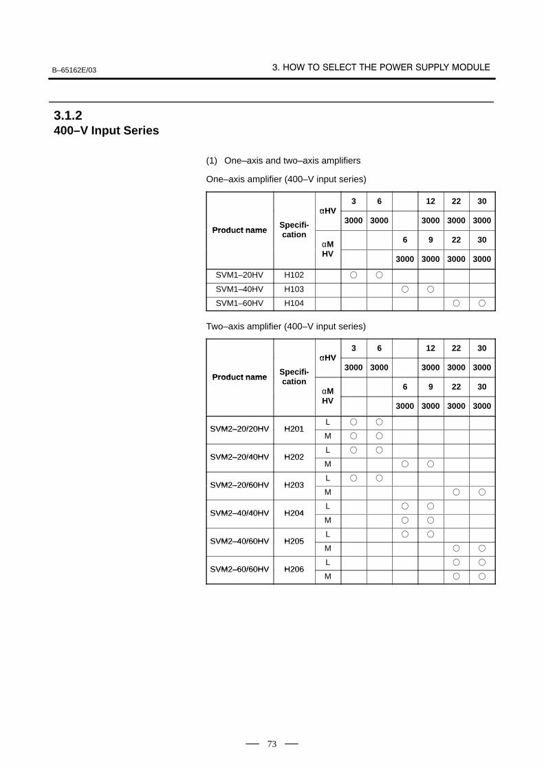
B–65162E/03
73
(1) One–axis and two–axis amplifiers
One–axis amplifier (400–V input series)
αHV3 6 12 22 30
Prod ct nameSpecifi-
αHV3000 3000 3000 3000 3000
Product nameSpecification
αM 6 9 22 30αMHV
3000 3000 3000 3000
SVM1–20HV H102
SVM1–40HV H103
SVM1–60HV H104
Two–axis amplifier (400–V input series)
αHV3 6 12 22 30
Prod ct nameSpecifi-
αHV3000 3000 3000 3000 3000
Product nameSpecification
αM 6 9 22 30αMHV
3000 3000 3000 3000
SVM2–20/20HV H201L
SVM2–20/20HV H201M
SVM2–20/40HV H202L
SVM2–20/40HV H202M
SVM2–20/60HV H203L
SVM2–20/60HV H203M
SVM2–40/40HV H204L
SVM2–40/40HV H204M
SVM2–40/60HV H205L
SVM2–40/60HV H205M
SVM2–60/60HV H206L
SVM2–60/60HV H206M
3.1.2400–V Input Series
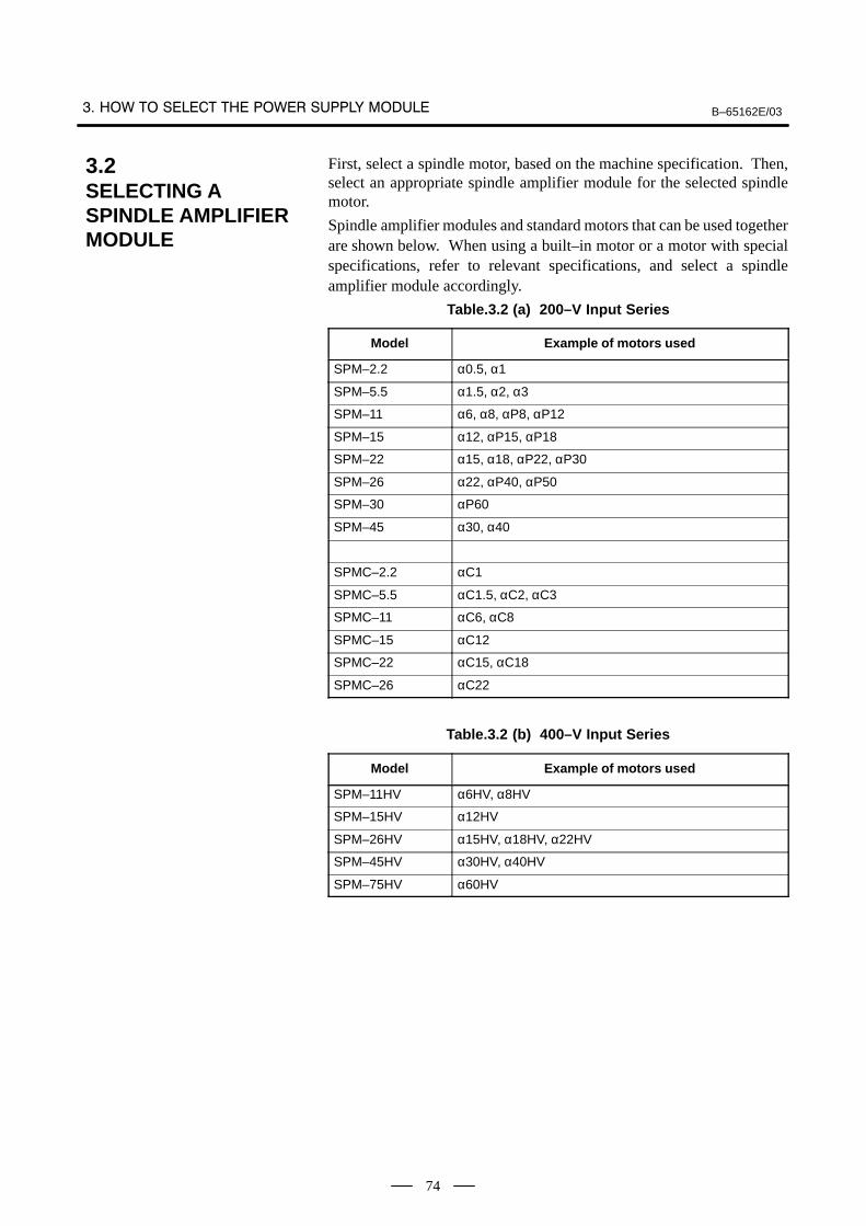
B–65162E/03
74
First, select a spindle motor, based on the machine specification. Then,select an appropriate spindle amplifier module for the selected spindlemotor.
Spindle amplifier modules and standard motors that can be used togetherare shown below. When using a built–in motor or a motor with specialspecifications, refer to relevant specifications, and select a spindleamplifier module accordingly.
Table.3.2 (a) 200–V Input Series
Model Example of motors used
SPM–2.2 α0.5, α1
SPM–5.5 α1.5, α2, α3
SPM–11 α6, α8, αP8, αP12
SPM–15 α12, αP15, αP18
SPM–22 α15, α18, αP22, αP30
SPM–26 α22, αP40, αP50
SPM–30 αP60
SPM–45 α30, α40
SPMC–2.2 αC1
SPMC–5.5 αC1.5, αC2, αC3
SPMC–11 αC6, αC8
SPMC–15 αC12
SPMC–22 αC15, αC18
SPMC–26 αC22
Table.3.2 (b) 400–V Input Series
Model Example of motors used
SPM–11HV α6HV, α8HV
SPM–15HV α12HV
SPM–26HV α15HV, α18HV, α22HV
SPM–45HV α30HV, α40HV
SPM–75HV α60HV
3.2SELECTING A SPINDLE AMPLIFIER MODULE
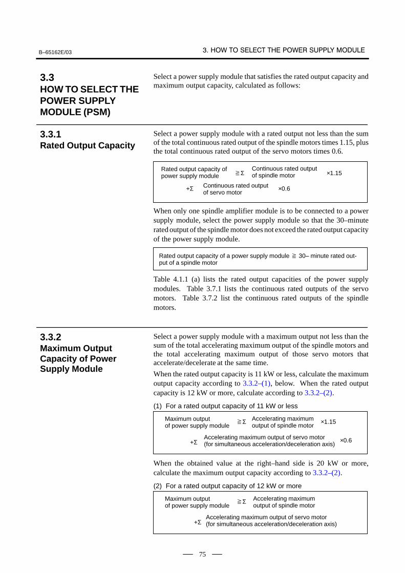
B–65162E/03
75
Select a power supply module that satisfies the rated output capacity andmaximum output capacity, calculated as follows:
Select a power supply module with a rated output not less than the sumof the total continuous rated output of the spindle motors times 1.15, plusthe total continuous rated output of the servo motors times 0.6.
Rated output capacity ofpower supply module
Continuous rated outputof spindle motor
Continuous rated outputof servo motor
Σ ×1.15
+Σ ×0.6
When only one spindle amplifier module is to be connected to a powersupply module, select the power supply module so that the 30–minuterated output of the spindle motor does not exceed the rated output capacityof the power supply module.
Rated output capacity of a power supply module 30– minute rated out-put of a spindle motor
Table 4.1.1 (a) lists the rated output capacities of the power supplymodules. Table 3.7.1 lists the continuous rated outputs of the servomotors. Table 3.7.2 list the continuous rated outputs of the spindlemotors.
Select a power supply module with a maximum output not less than thesum of the total accelerating maximum output of the spindle motors andthe total accelerating maximum output of those servo motors thataccelerate/decelerate at the same time.
When the rated output capacity is 11 kW or less, calculate the maximumoutput capacity according to 3.3.2–(1), below. When the rated outputcapacity is 12 kW or more, calculate according to 3.3.2–(2).
(1) For a rated output capacity of 11 kW or less
Maximum output of power supply module
Accelerating maximum output of spindle motor
Accelerating maximum output of servo motor(for simultaneous acceleration/deceleration axis)
Σ ×1.15
+Σ ×0.6
When the obtained value at the right–hand side is 20 kW or more,calculate the maximum output capacity according to 3.3.2–(2).
(2) For a rated output capacity of 12 kW or more
Maximum output of power supply module
Accelerating maximum output of spindle motor
Accelerating maximum output of servo motor(for simultaneous acceleration/deceleration axis)
Σ
+Σ
3.3HOW TO SELECT THEPOWER SUPPLY MODULE (PSM)
3.3.1Rated Output Capacity
3.3.2Maximum OutputCapacity of PowerSupply Module
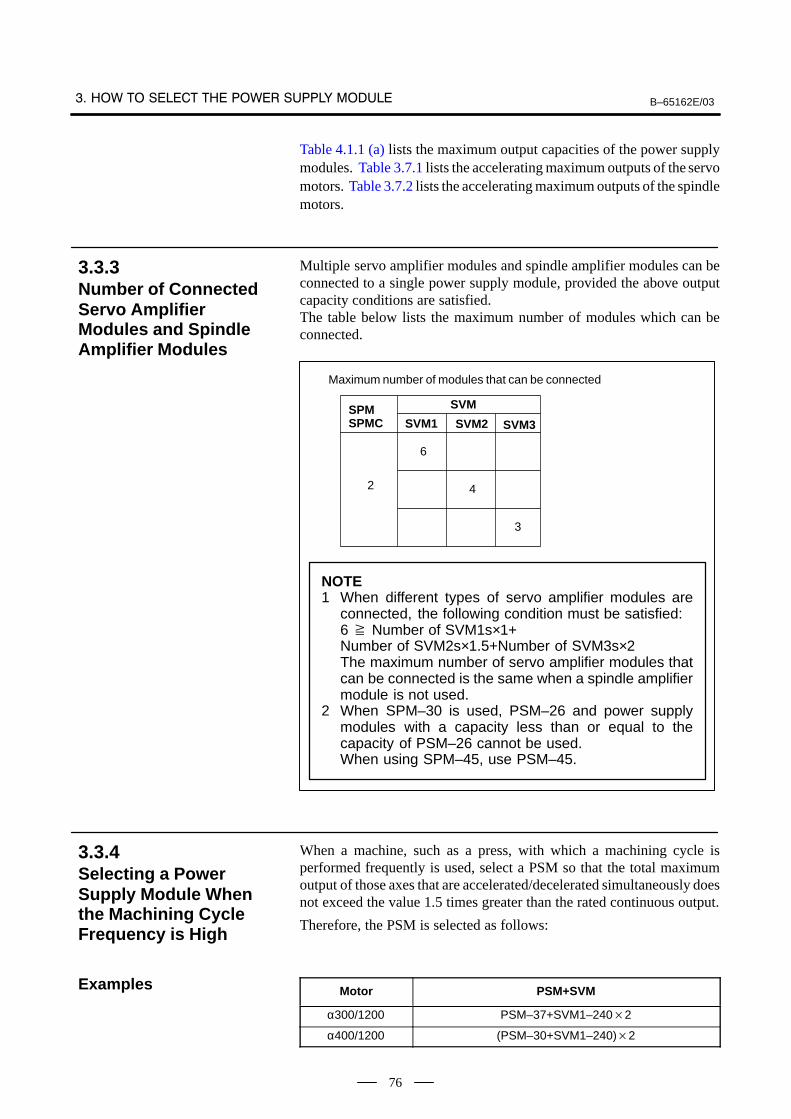
B–65162E/03
76
Table 4.1.1 (a) lists the maximum output capacities of the power supplymodules. Table 3.7.1 lists the accelerating maximum outputs of the servomotors. Table 3.7.2 lists the accelerating maximum outputs of the spindlemotors.
Multiple servo amplifier modules and spindle amplifier modules can beconnected to a single power supply module, provided the above outputcapacity conditions are satisfied.The table below lists the maximum number of modules which can beconnected.
2
6
4
3
Maximum number of modules that can be connected
SVM
SVM1 SVM2 SVM3SPMSPMC
NOTE1 When different types of servo amplifier modules are
connected, the following condition must be satisfied:6 Number of SVM1s×1+Number of SVM2s×1.5+Number of SVM3s×2The maximum number of servo amplifier modules thatcan be connected is the same when a spindle amplifiermodule is not used.
2 When SPM–30 is used, PSM–26 and power supplymodules with a capacity less than or equal to thecapacity of PSM–26 cannot be used.When using SPM–45, use PSM–45.
When a machine, such as a press, with which a machining cycle isperformed frequently is used, select a PSM so that the total maximumoutput of those axes that are accelerated/decelerated simultaneously doesnot exceed the value 1.5 times greater than the rated continuous output.
Therefore, the PSM is selected as follows:
Motor PSM+SVM
α300/1200 PSM–37+SVM1–2402
α400/1200 (PSM–30+SVM1–240)2
3.3.3Number of ConnectedServo AmplifierModules and SpindleAmplifier Modules
3.3.4Selecting a PowerSupply Module Whenthe Machining CycleFrequency is High
Examples
B–65162E/03
77
(1) When two α22/2000 servo motors and one αP50 spindle motor are
used
Servo motor α22/2000Continuous rated output : 3.8 kWMaximum output at acceleration : 7.5 kW
Spindle motor αP50Continuous rated output : 22 kWMaximum output at acceleration : 36 kW
Rated output capacity of power supply module Σ spindle motorcontinuous rated output1.15 + Σ servo motor continuous ratedoutput0.6= 221.15 + 3.820.6= 29.86 Condition 1Maximum output capacity of the power supply module Σmaximum output of the spindle motor at acceleration + Σ maximumoutput of the servo motors at acceleration (simultaneousacceleration/deceleration)= 36 + 7.52= 51.0 Condition 2According to conditions 1 and 2, PSM–30 is selected as the powersupply module.
(2) When two α6/3000 servo motors and one α22/2000 servo motor, and
one α3 spindle motor are used
Servo motor α6/3000Continuous rated output : 1.4 kWMaximum output at acceleration : 6.2 kW
Servo motor α22/2000Continuous rated output : 3.8 kWMaximum output at acceleration : 7.5 kW
Spindle motor α3Continuous rated output : 3.7 kWMaximum output at acceleration : 6.6 kW
Rated output capacity of power supply module Σ spindle motorcontinuous rated output1.15 + Σ servo motor continuous ratedoutput0.6= 3.71.15 + (1.42 + 3.8)0.6= 8.215 Condition 3Since the rated output capacity of the power supply module is nothigher than 11kW, the maximum output capacity can be obtainedfrom the following expression:
3.3.5Example of Selecting aPower Supply Module(PSM)

B–65162E/03
78
Maximum output capacity of the power supply module Σmaximum output of the spindle motor at acceleration + Σ maximumoutput of the servo motors at acceleration (simultaneousacceleration/deceleration)0.6= 6.6 + (6.22 + 7.5)0.6= 18.54 Condition 4According to conditions 3 and 4, PSM–11 is selected as the powersupply module.
B–65162E/03
79
Select a power supply module that satisfies the rated output capacity andmaximum output capacity, calculated as follows :
Select a power supply module (PSMR) with a rated output not less thanthe sum of the total continuous rated output of the spindle motors times1.15, plus the total continuous rated output of the servo motors times 0.6.
Rated output capacity ofpower supply module(PSMR)
Continuous rated outputof spindle motor
Continuous rated outputof servo motor
Σ ×1.15
+Σ ×0.6
When only one spindle amplifier module is connected to a power supplymodule, the power supply module must be selected so that the 30–minuterated output of the spindle motor does not exceed the rated output capacityof the power supply module.
Rated output capacity of a power supply module 30– minute rated out-put of a spindle motor
Table 4.1.1 (b) lists the rated output capacities of the power supplymodules (PSMR). Table 3.7.1 lists the continuous rated outputs of theservo motors. Table 3.7.2 list the continuous rated outputs of the spindlemotors.
Select a power supply module (PSMR) with a maximum output not lessthan the sum of the total accelerating maximum output of the spindlemotors and the total accelerating maximum output of those servo motorsthat accelerate/decelerate at the same time.
Maximum output of power supply module(PSMR)
Accelerating maximum output of spindle motor
Accelerating maximum output of servo motor(for simultaneous acceleration/deceleration axis)
Σ
+Σ
Table 4.1.1 (b) lists the maximum output capacities of the power supplymodules. Table 3.7.1 lists the accelerating maximum outputs of the servomotors. Table 3.7.2 list the accelerating maximum outputs of the spindlemotors.
Multiple servo amplifier modules and spindle amplifier modules can beconnected to a single power supply module, provided the above outputcapacity conditions are satisfied.The table below lists the maximum number of modules which can beconnected.
3.4HOW TO SELECT THEPOWER SUPPLY MODULE (PSMR)
3.4.1Rated Output Capacity (PSMR)
3.4.2Maximum OutputCapacity of PowerSupply Module (PSMR)
3.4.3Number of ConnectedServo AmplifierModules and SpindleAmplifier Modules
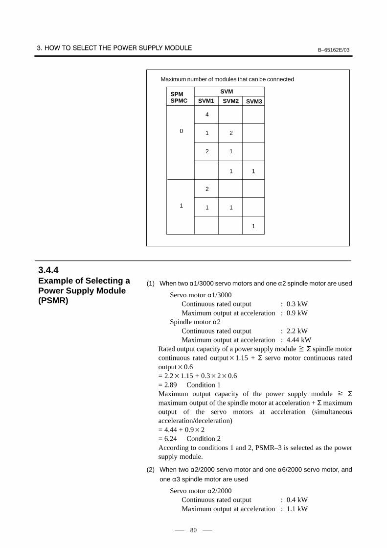
B–65162E/03
80
0
4
2
Maximum number of modules that can be connected
SVM
SVM1 SVM2 SVM3SPMSPMC
1
2 1
1 1
1
2
11
1
(1) When two α1/3000 servo motors and one α2 spindle motor are used
Servo motor α1/3000Continuous rated output : 0.3 kWMaximum output at acceleration : 0.9 kW
Spindle motor α2Continuous rated output : 2.2 kWMaximum output at acceleration : 4.44 kW
Rated output capacity of a power supply module Σ spindle motorcontinuous rated output1.15 + Σ servo motor continuous ratedoutput0.6= 2.21.15 + 0.320.6= 2.89 Condition 1Maximum output capacity of the power supply module Σmaximum output of the spindle motor at acceleration + Σ maximumoutput of the servo motors at acceleration (simultaneousacceleration/deceleration)= 4.44 + 0.92= 6.24 Condition 2According to conditions 1 and 2, PSMR–3 is selected as the powersupply module.
(2) When two α2/2000 servo motor and one α6/2000 servo motor, and
one α3 spindle motor are used
Servo motor α2/2000Continuous rated output : 0.4 kWMaximum output at acceleration : 1.1 kW
3.4.4Example of Selecting aPower Supply Module(PSMR)
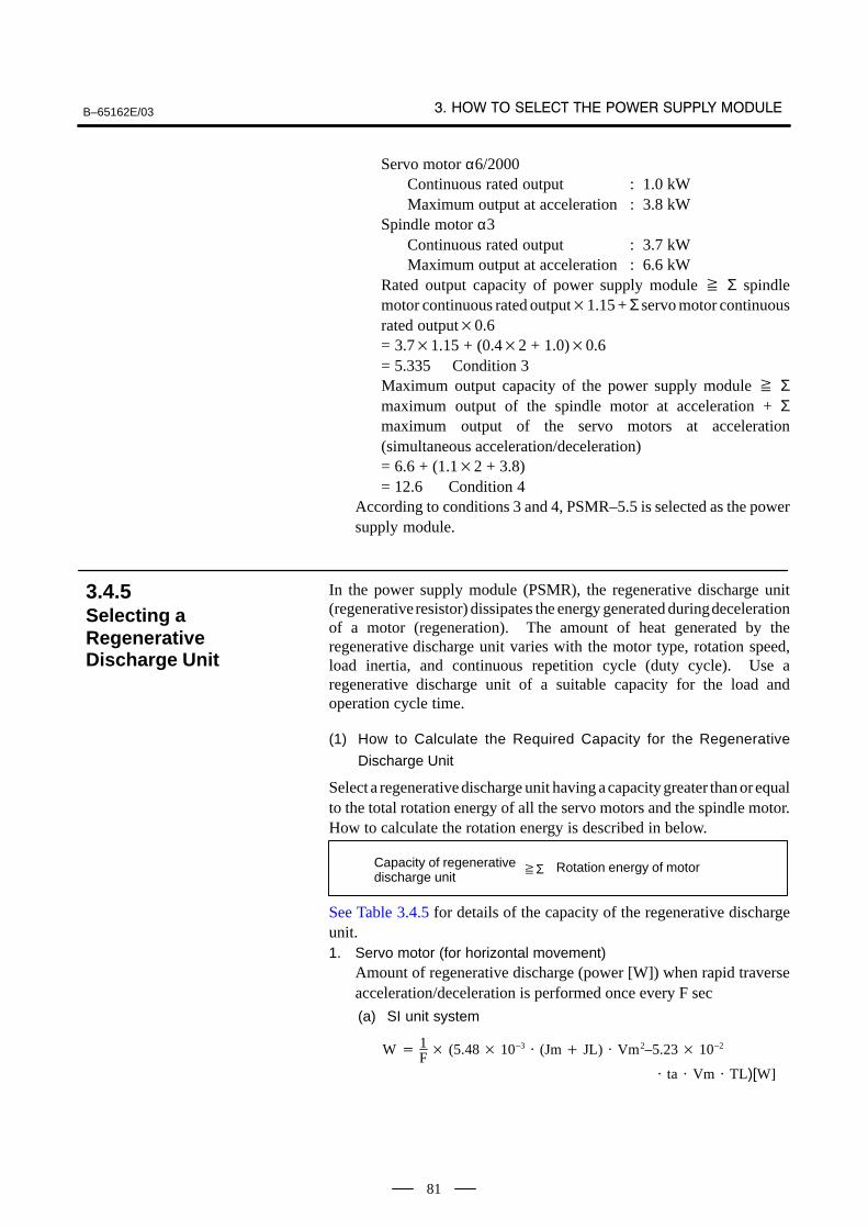
B–65162E/03
81
Servo motor α6/2000Continuous rated output : 1.0 kWMaximum output at acceleration : 3.8 kW
Spindle motor α3Continuous rated output : 3.7 kWMaximum output at acceleration : 6.6 kW
Rated output capacity of power supply module Σ spindlemotor continuous rated output1.15 + Σ servo motor continuousrated output0.6= 3.71.15 + (0.42 + 1.0)0.6= 5.335 Condition 3Maximum output capacity of the power supply module Σmaximum output of the spindle motor at acceleration + Σmaximum output of the servo motors at acceleration(simultaneous acceleration/deceleration) = 6.6 + (1.12 + 3.8) = 12.6 Condition 4
According to conditions 3 and 4, PSMR–5.5 is selected as the powersupply module.
In the power supply module (PSMR), the regenerative discharge unit(regenerative resistor) dissipates the energy generated during decelerationof a motor (regeneration). The amount of heat generated by theregenerative discharge unit varies with the motor type, rotation speed,load inertia, and continuous repetition cycle (duty cycle). Use aregenerative discharge unit of a suitable capacity for the load andoperation cycle time.
(1) How to Calculate the Required Capacity for the Regenerative
Discharge Unit
Select a regenerative discharge unit having a capacity greater than or equalto the total rotation energy of all the servo motors and the spindle motor.How to calculate the rotation energy is described in below.
ΣCapacity of regenerativedischarge unit
Rotation energy of motor
See Table 3.4.5 for details of the capacity of the regenerative dischargeunit.1. Servo motor (for horizontal movement)
Amount of regenerative discharge (power [W]) when rapid traverseacceleration/deceleration is performed once every F sec
(a) SI unit system
W 1F (5.48 10–3
(Jm JL) Vm2–5.23 10–2
ta Vm TL)[W]
3.4.5Selecting aRegenerativeDischarge Unit
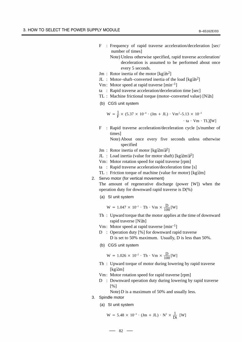
B–65162E/03
82
F : Frequency of rapid traverse acceleration/deceleration [sec/ number of times]Note) Unless otherwise specified, rapid traverse acceleration/
deceleration is assumed to be performed about onceevery 5 seconds.
Jm : Rotor inertia of the motor [kg⋅m2]JL : Motor–shaft–converted inertia of the load [kg⋅m2]Vm: Motor speed at rapid traverse [min–1]ta : Rapid traverse acceleration/deceleration time [sec]TL : Machine frictional torque (motor–converted value) [N⋅m]
(b) CGS unit system
W 1F (5.37 10–4
(Jm JL) Vm2–5.13 10–3
ta Vm TL)[W]
F : Rapid traverse acceleration/deceleration cycle [s/number oftimes]Note) About once every five seconds unless otherwise
specifiedJm : Rotor inertia of motor [kg⋅cm⋅s2]JL : Load inertia (value for motor shaft) [kg⋅cm⋅s2]Vm: Motor rotation speed for rapid traverse [rpm]ta : Rapid traverse acceleration/deceleration time [s]TL : Friction torque of machine (value for motor) [kg⋅cm]
2. Servo motor (for vertical movement)The amount of regenerative discharge (power [W]) when theoperation duty for downward rapid traverse is D(%)
(a) SI unit system
W 1.047 10–1 Th Vm
D100
[W]
Th : Upward torque that the motor applies at the time of downwardrapid traverse [N⋅m]
Vm: Motor speed at rapid traverse [min–1]D : Operation duty [%] for downward rapid traverse
D is set to 50% maximum. Usually, D is less than 50%.
(b) CGS unit system
W 1.026 10–2 Th Vm
D100
[W]
Th : Upward torque of motor during lowering by rapid traverse [kg⋅cm]
Vm: Motor rotation speed for rapid traverse [rpm]D : Downward operation duty during lowering by rapid traverse
[%]Note) D is a maximum of 50% and usually less.
3. Spindle motor
(a) SI unit system
W 5.48 10–3 (Jm JL) N2
1Dt
[W]
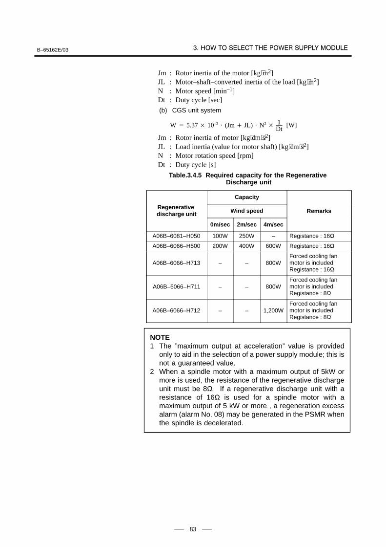
B–65162E/03
83
Jm : Rotor inertia of the motor [kg⋅m2]JL : Motor–shaft–converted inertia of the load [kg⋅m2]N : Motor speed [min–1]Dt : Duty cycle [sec]
(b) CGS unit system
W 5.37 10–2 (Jm JL) N2
1Dt
[W]
Jm : Rotor inertia of motor [kg⋅cm⋅s2]JL : Load inertia (value for motor shaft) [kg⋅cm⋅s2]N : Motor rotation speed [rpm]Dt : Duty cycle [s]
Table.3.4.5 Required capacity for the Regenerative Discharge unit
Capacity
Regenerative discharge unit Wind speed Remarksdischarge unit
0m/sec 2m/sec 4m/sec
A06B–6081–H050 100W 250W – Registance : 16Ω
A06B–6066–H500 200W 400W 600W Registance : 16Ω
A06B–6066–H713 – – 800WForced cooling fan motor is includedRegistance : 16Ω
A06B–6066–H711 – – 800WForced cooling fan motor is includedRegistance : 8Ω
A06B–6066–H712 – – 1,200WForced cooling fan motor is includedRegistance : 8Ω
NOTE1 The ”maximum output at acceleration” value is provided
only to aid in the selection of a power supply module; this isnot a guaranteed value.
2 When a spindle motor with a maximum output of 5kW ormore is used, the resistance of the regenerative dischargeunit must be 8Ω. If a regenerative discharge unit with aresistance of 16Ω is used for a spindle motor with amaximum output of 5 kW or more , a regeneration excessalarm (alarm No. 08) may be generated in the PSMR whenthe spindle is decelerated.
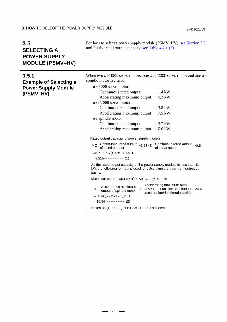
B–65162E/03
84
For how to select a power supply module (PSMV–HV), see Section 3.3,and for the rated output capacity, see Table 4.2.1 (3).
When two α6/3000 servo motors, one α22/2000 servo motor and one α3spindle motor are used
α6/3000 servo motorContinuous rated output : 1.4 kWAccelerating maximum output : 6.2 kW
α22/2000 servo motorContinuous rated output : 3.8 kWAccelerating maximum output : 7.5 kW
α3 spindle motorContinuous rated output : 3.7 kWAccelerating maximum output : 6.6 kW
Σ
Rated output capacity of power supply module
×1.15+ΣContinuous rated outputof spindle motor
Continuous rated outputof servo motor
×0.6
\×+
= 8.215 (1)
Maximum output capacity of power supply module
ΣAccelerating maximumoutput of spindle motor +Σ
Accelerating maximum outputof servo motor (for simultaneous acceleration/deceleration axis)
×+
= 18.54 (2)
As the rated output capacity of the power supply module is less than 11kW, the following formula is used for calculating the maximum output ca-pacity:
×0.6
Based on (1) and (2), the PSM–11HV is selected.
3.5SELECTING A POWER SUPPLY MODULE (PSMV–HV)
3.5.1Example of Selecting aPower Supply Module(PSMV–HV)
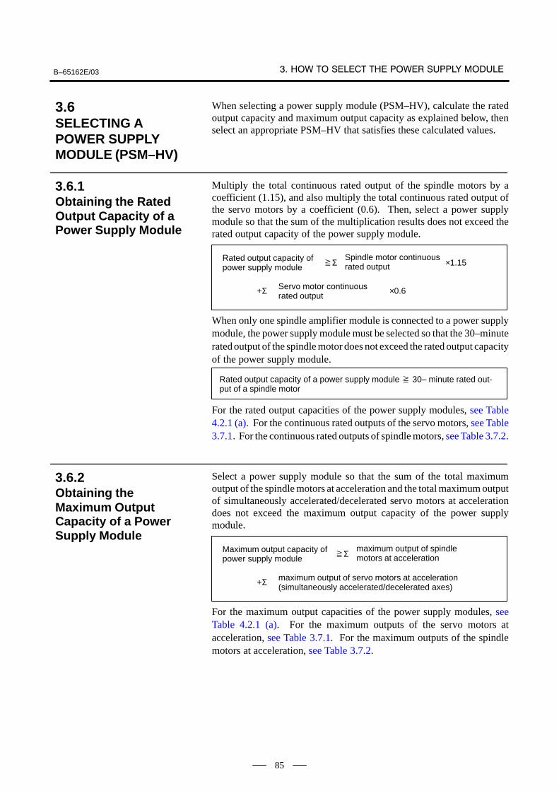
B–65162E/03
85
When selecting a power supply module (PSM–HV), calculate the ratedoutput capacity and maximum output capacity as explained below, thenselect an appropriate PSM–HV that satisfies these calculated values.
Multiply the total continuous rated output of the spindle motors by acoefficient (1.15), and also multiply the total continuous rated output ofthe servo motors by a coefficient (0.6). Then, select a power supplymodule so that the sum of the multiplication results does not exceed therated output capacity of the power supply module.
Rated output capacity ofpower supply module
Spindle motor continuousrated output
Servo motor continuousrated output
Σ ×1.15
+Σ ×0.6
When only one spindle amplifier module is connected to a power supplymodule, the power supply module must be selected so that the 30–minuterated output of the spindle motor does not exceed the rated output capacityof the power supply module.
Rated output capacity of a power supply module 30– minute rated out-put of a spindle motor
For the rated output capacities of the power supply modules, see Table4.2.1 (a). For the continuous rated outputs of the servo motors, see Table3.7.1. For the continuous rated outputs of spindle motors, see Table 3.7.2.
Select a power supply module so that the sum of the total maximumoutput of the spindle motors at acceleration and the total maximum outputof simultaneously accelerated/decelerated servo motors at accelerationdoes not exceed the maximum output capacity of the power supplymodule.
Maximum output capacity of power supply module
maximum output of spindlemotors at acceleration
maximum output of servo motors at acceleration(simultaneously accelerated/decelerated axes)
Σ
+Σ
For the maximum output capacities of the power supply modules, seeTable 4.2.1 (a). For the maximum outputs of the servo motors atacceleration, see Table 3.7.1. For the maximum outputs of the spindlemotors at acceleration, see Table 3.7.2.
3.6SELECTING A POWER SUPPLY MODULE (PSM–HV)
3.6.1Obtaining the RatedOutput Capacity of aPower Supply Module
3.6.2Obtaining theMaximum OutputCapacity of a PowerSupply Module
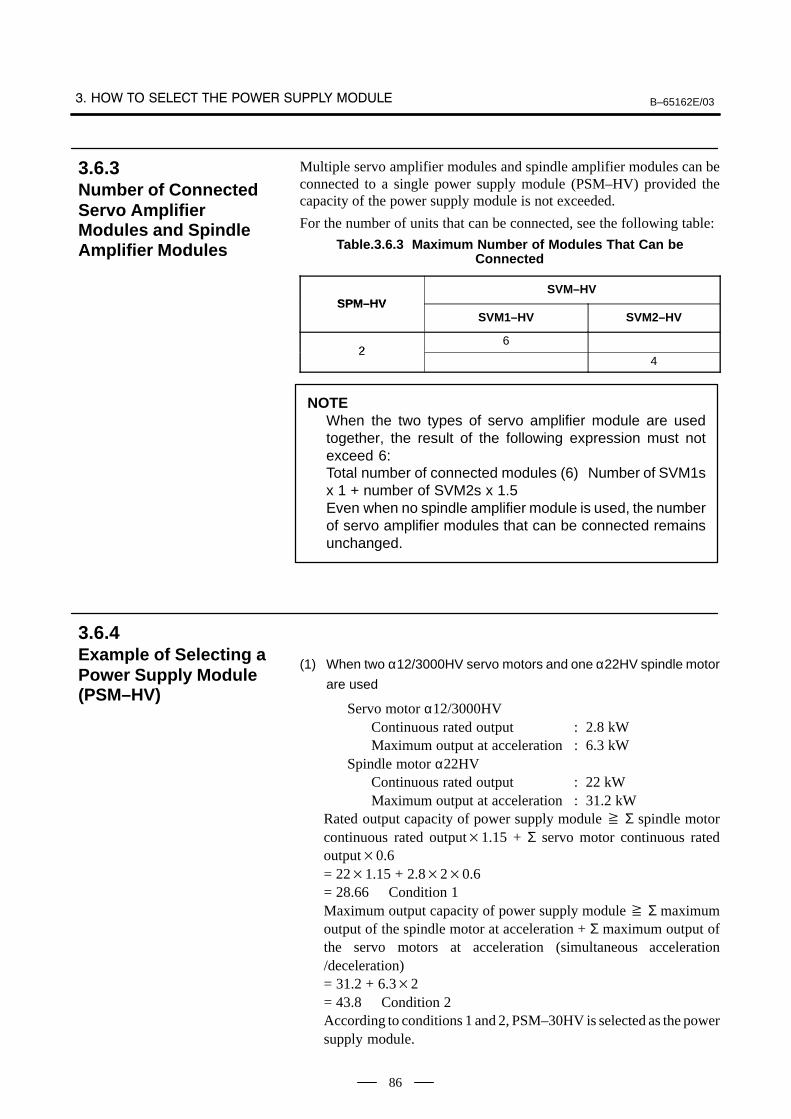
B–65162E/03
86
Multiple servo amplifier modules and spindle amplifier modules can beconnected to a single power supply module (PSM–HV) provided thecapacity of the power supply module is not exceeded.
For the number of units that can be connected, see the following table:
Table.3.6.3 Maximum Number of Modules That Can beConnected
SPM–HVSVM–HV
SPM–HVSVM1–HV SVM2–HV
26
24
NOTEWhen the two types of servo amplifier module are usedtogether, the result of the following expression must notexceed 6:Total number of connected modules (6) Number of SVM1sx 1 + number of SVM2s x 1.5Even when no spindle amplifier module is used, the numberof servo amplifier modules that can be connected remainsunchanged.
(1) When two α12/3000HV servo motors and one α22HV spindle motor
are used
Servo motor α12/3000HVContinuous rated output : 2.8 kWMaximum output at acceleration : 6.3 kW
Spindle motor α22HVContinuous rated output : 22 kWMaximum output at acceleration : 31.2 kW
Rated output capacity of power supply module Σ spindle motorcontinuous rated output1.15 + Σ servo motor continuous ratedoutput0.6= 221.15 + 2.820.6= 28.66 Condition 1Maximum output capacity of power supply module Σ maximumoutput of the spindle motor at acceleration + Σ maximum output ofthe servo motors at acceleration (simultaneous acceleration/deceleration)= 31.2 + 6.32= 43.8 Condition 2According to conditions 1 and 2, PSM–30HV is selected as the powersupply module.
3.6.3Number of ConnectedServo AmplifierModules and SpindleAmplifier Modules
3.6.4Example of Selecting aPower Supply Module(PSM–HV)
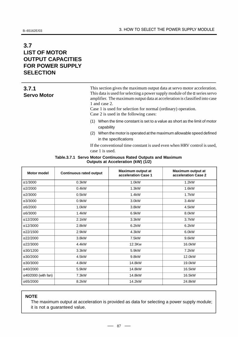
B–65162E/03
87
This section gives the maximum output data at servo motor acceleration.This data is used for selecting a power supply module of the α series servoamplifier. The maximum output data at acceleration is classified into case1 and case 2.Case 1 is used for selection for normal (ordinary) operation.Case 2 is used in the following cases:
(1) When the time constant is set to a value as short as the limit of motor
capability
(2) When the motor is operated at the maximum allowable speed defined
in the specifications
If the conventional time constant is used even when HRV control is used,case 1 is used.
Table.3.7.1 Servo Motor Continuous Rated Outputs and Maximum Outputs at Acceleration (kW) (1/2)
Motor model Continuous rated output Maximum output at acceleration Case 1
Maximum output at acceleration Case 2
α1/3000 0.3kW 1.0kW 1.2kW
α2/2000 0.4kW 1.3kW 1.6kW
α2/3000 0.5kW 1.4kW 1.7kW
α3/3000 0.9kW 3.0kW 3.4kW
α6/2000 1.0kW 3.8kW 4.5kW
α6/3000 1.4kW 6.9kW 8.0kW
α12/2000 2.1kW 3.3kW 3.7kW
α12/3000 2.8kW 6.2kW 6.2kW
α22/1500 2.9kW 4.3kW 6.0kW
α22/2000 3.8kW 7.5kW 9.6kW
α22/3000 4.4kW 12.3Kw 16.0kW
α30/1200 3.3kW 5.9kW 7.2kW
α30/2000 4.5kW 9.8kW 12.0kW
α30/3000 4.8kW 14.8kW 19.0kW
α40/2000 5.9kW 14.8kW 16.5kW
α40/2000 (with fan) 7.3kW 14.8kW 16.5kW
α65/2000 8.2kW 14.2kW 24.8kW
NOTEThe maximum output at acceleration is provided as data for selecting a power supply module;it is not a guaranteed value.
3.7LIST OF MOTOR OUTPUT CAPACITIESFOR POWER SUPPLYSELECTION
3.7.1Servo Motor

B–65162E/03
88
Table.3.7.1 Servo Motor Continuous Rated Outputs and Maximum Outputs at Acceleration (kW) (2/2)
Motor model Continuous rated output Maximum output at acceleration Case 1
Maximum output at acceleration Case 2
α100/2000 10.3kW 21.8kW 35.1kW
α150/2000 12.5kW 26.8kW 38.0kW
α300/1200 30kW 54kW 61kW
α400/1200 35kW 59kW 67kW
αM2/3000 0.7kW 1.9kW 2.2kW
αM2.5/3000 0.8kW 2.3kW 2.7kW
αM6/3000 1.4kW 4.8kW 5.6kW
αM9/3000 1.8kW 7.4kW 8.5kW
αM22/3000 3.8kW 11.1kW 12.6kW
αM30/3000 3.8kW 17.6kW 19.9kW
αM40/3000 (130A) 7.0KW 18.4Kw 20.7kW
αM40/3000 (with fan) (240A, 360A) 10KW 30.2kW 34kW
αC3/2000 0.3kW 1.7kW 2.0kW
αC6/2000 0.6kW 2.4kW 2.8kW
αC12/2000 1.0kW 2.0kW 2.3kW
αC22/1500 1.5kW 4.3kW 6.0kW
αL6/3000 1.4kW 2.5kW 4.2kW
αL9/3000 2.0kW 5.0kW 8.9kW
αL25/3000 3.5kW 9.8kW 17.4kW
αL50/2000 6.0kW 12.3kW 20.3kW
β0.5/3000 0.2kW 0.5kW 0.7kW
β1/3000 0.3kW 0.8kW 1.0kW
β2/3000 0.5kW 1.2kW 1.4kW
β3/3000 0.5kW 1.6kW 2.2kW
β6/2000 0.9kW 2.4kW 2.8kW
α3/3000HV 0.9kW 2.8kW 4.3kW
α6/3000HV 1.4kW 3.8kW 5.5kW
α12/3000HV 2.8kW 6.3kW 7.1kW
α22/3000HV 4.0kW 10.1kW 12.6kW
α30/3000HV 4.0kW 11.3kW 13.5kW
αM6/3000HV 1.4kW 5.0kW 5.5kW
αM9/3000HV 1.8kW 8.4kW 9.6kW
αM22/3000HV 3.8kW 11.1kW 11.2kW
αM30/3000HV 3.8kW 14.8kW 17.8kW
NOTEThe maximum output at acceleration is provided as data for selecting a power supply module;it is not a guaranteed value.
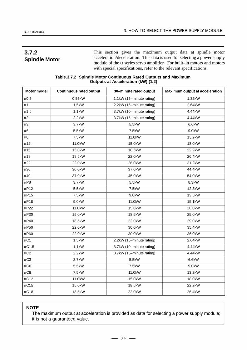
B–65162E/03
89
This section gives the maximum output data at spindle motoracceleration/deceleration. This data is used for selecting a power supplymodule of the α series servo amplifier. For built–in motors and motorswith special specifications, refer to the relevant specifications.
Table.3.7.2 Spindle Motor Continuous Rated Outputs and Maximum Outputs at Acceleration (kW) (1/2)
Motor model Continuous rated output 30–minute rated output Maximum output at acceleration
α0.5 0.55kW 1.1kW (15–minute rating) 1.32kW
α1 1.5kW 2.2kW (15–minute rating) 2.64kW
α1.5 1.1kW 3.7kW (10–minute rating) 4.44kW
α2 2.2kW 3.7kW (15–minute rating) 4.44kW
α3 3.7kW 5.5kW 6.6kW
α6 5.5kW 7.5kW 9.0kW
α8 7.5kW 11.0kW 13.2kW
α12 11.0kW 15.0kW 18.0kW
α15 15.0kW 18.5kW 22.2kW
α18 18.5kW 22.0kW 26.4kW
α22 22.0kW 26.0kW 31.2kW
α30 30.0kW 37.0kW 44.4kW
α40 37.0kW 45.0kW 54.0kW
αP8 3.7kW 5.5kW 8.3kW
αP12 5.5kW 7.5kW 12.3kW
αP15 7.5kW 9.0kW 13.5kW
αP18 9.0kW 11.0kW 15.1kW
αP22 11.0kW 15.0kW 20.0kW
αP30 15.0kW 18.5kW 25.0kW
αP40 18.5kW 22.0kW 29.0kW
αP50 22.0kW 30.0kW 35.4kW
αP60 22.0kW 30.0kW 36.0kW
αC1 1.5kW 2.2kW (15–minute rating) 2.64kW
αC1.5 1.1kW 3.7kW (10–minute rating) 4.44kW
αC2 2.2kW 3.7kW (15–minute rating) 4.44kW
αC3 3.7kW 5.5kW 6.6kW
αC6 5.5kW 7.5kW 9.0kW
αC8 7.5kW 11.0kW 13.2kW
αC12 11.0kW 15.0kW 18.0kW
αC15 15.0kW 18.5kW 22.2kW
αC18 18.5kW 22.0kW 26.4kW
NOTEThe maximum output at acceleration is provided as data for selecting a power supply module;it is not a guaranteed value.
3.7.2Spindle Motor
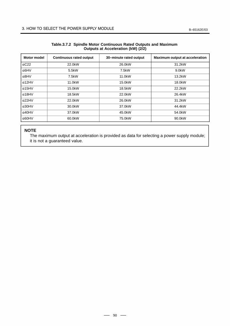
B–65162E/03
90
Table.3.7.2 Spindle Motor Continuous Rated Outputs and Maximum Outputs at Acceleration (kW) (2/2)
Motor model Continuous rated output 30–minute rated output Maximum output at acceleration
αC22 22.0kW 26.0kW 31.2kW
α6HV 5.5kW 7.5kW 9.0kW
α8HV 7.5kW 11.0kW 13.2kW
α12HV 11.0kW 15.0kW 18.0kW
α15HV 15.0kW 18.5kW 22.2kW
α18HV 18.5kW 22.0kW 26.4kW
α22HV 22.0kW 26.0kW 31.2kW
α30HV 30.0kW 37.0kW 44.4kW
α40HV 37.0kW 45.0kW 54.0kW
α60HV 60.0kW 75.0kW 90.0kW
NOTEThe maximum output at acceleration is provided as data for selecting a power supply module;it is not a guaranteed value.

B–65162E/03 4. SPECIFICATIONS
91
4
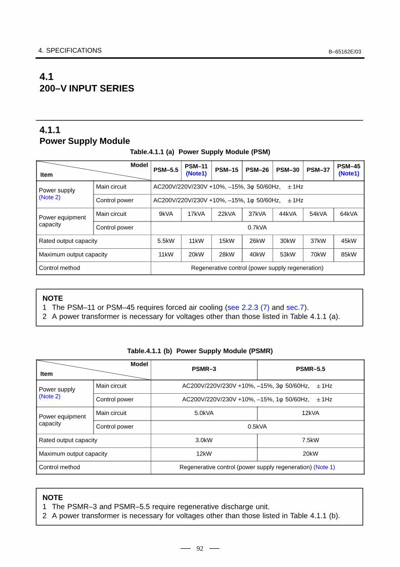
4. SPECIFICATIONS B–65162E/03
92
Table.4.1.1 (a) Power Supply Module (PSM)
Model
ItemPSM–5.5 PSM–11
(Note1) PSM–15 PSM–26 PSM–30 PSM–37 PSM–45(Note1)
Power supply Main circuit AC200V/220V/230V +10%, –15%, 3φ 50/60Hz, 1Hz
Power su ly (Note 2) Control power AC200V/220V/230V +10%, –15%, 1φ 50/60Hz, 1Hz
Power equipment Main circuit 9kVA 17kVA 22kVA 37kVA 44kVA 54kVA 64kVA
Power equi ment capacity Control power 0.7kVA
Rated output capacity 5.5kW 11kW 15kW 26kW 30kW 37kW 45kW
Maximum output capacity 11kW 20kW 28kW 40kW 53kW 70kW 85kW
Control method Regenerative control (power supply regeneration)
NOTE1 The PSM–11 or PSM–45 requires forced air cooling (see 2.2.3 (7) and sec.7).2 A power transformer is necessary for voltages other than those listed in Table 4.1.1 (a).
Table.4.1.1 (b) Power Supply Module (PSMR)
Model
ItemPSMR–3 PSMR–5.5
Power supply Main circuit AC200V/220V/230V +10%, –15%, 3φ 50/60Hz, 1Hz
Power su ly (Note 2) Control power AC200V/220V/230V +10%, –15%, 1φ 50/60Hz, 1Hz
Power equipment Main circuit 5.0kVA 12kVA
Power equi ment capacity Control power 0.5kVA
Rated output capacity 3.0kW 7.5kW
Maximum output capacity 12kW 20kW
Control method Regenerative control (power supply regeneration) (Note 1)
NOTE1 The PSMR–3 and PSMR–5.5 require regenerative discharge unit.2 A power transformer is necessary for voltages other than those listed in Table 4.1.1 (b).
4.1200–V INPUT SERIES
4.1.1Power Supply Module
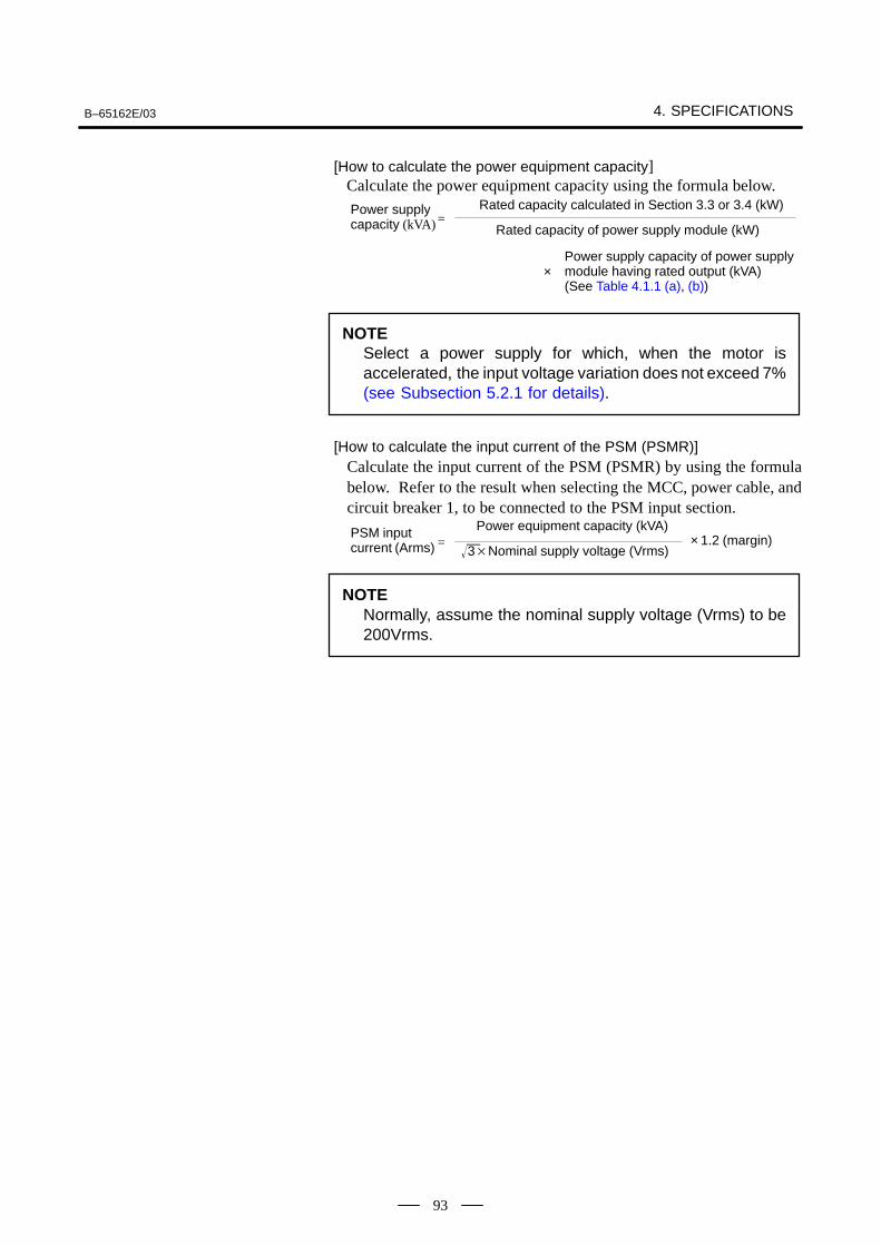
B–65162E/03 4. SPECIFICATIONS
93
[How to calculate the power equipment capacity] Calculate the power equipment capacity using the formula below.
Power supplycapacity (kVA)
Rated capacity calculated in Section 3.3 or 3.4 (kW)
Rated capacity of power supply module (kW) =
×Power supply capacity of power supplymodule having rated output (kVA)(See Table 4.1.1 (a), (b))
NOTESelect a power supply for which, when the motor isaccelerated, the input voltage variation does not exceed 7%(see Subsection 5.2.1 for details).
[How to calculate the input current of the PSM (PSMR)]Calculate the input current of the PSM (PSMR) by using the formulabelow. Refer to the result when selecting the MCC, power cable, andcircuit breaker 1, to be connected to the PSM input section.
PSM input current (Arms)
Power equipment capacity (kVA)
3Nominal supply voltage (Vrms) = × 1.2 (margin)
NOTENormally, assume the nominal supply voltage (Vrms) to be200Vrms.
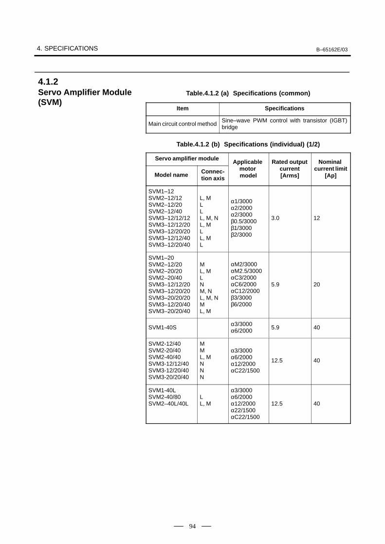
4. SPECIFICATIONS B–65162E/03
94
Table.4.1.2 (a) Specifications (common)
Item Specifications
Main circuit control methodSine–wave PWM control with transistor (IGBT)bridge
Table.4.1.2 (b) Specifications (individual) (1/2)
Servo amplifier module Applicable Rated output Nominal
Model name Connec-tion axis
Applicable motor model
Rated outputcurrent[Arms]
Nominal current limit
[Ap]
SVM1–12SVM2–12/12SVM2–12/20SVM2–12/40SVM3–12/12/12SVM3–12/12/20SVM3–12/20/20SVM3–12/12/40SVM3–12/20/40
L, MLLL, M, NL, MLL, ML
α1/3000α2/2000α2/3000β0.5/3000β1/3000β2/3000
3.0 12
SVM1–20SVM2–12/20SVM2–20/20SVM2–20/40SVM3–12/12/20SVM3–12/20/20SVM3–20/20/20SVM3–12/20/40SVM3–20/20/40
ML, MLNM, NL, M, NML, M
αM2/3000αM2.5/3000αC3/2000αC6/2000αC12/2000β3/3000β6/2000
5.9 20
SVM1-40Sα3/3000α6/2000 5.9 40
SVM2-12/40SVM2-20/40SVM2-40/40SVM3-12/12/40SVM3-12/20/40SVM3-20/20/40
MML, MNNN
α3/3000α6/2000α12/2000αC22/1500
12.5 40
SVM1-40LSVM2-40/80SVM2–40L/40L
LL, M
α3/3000α6/2000α12/2000α22/1500αC22/1500
12.5 40
4.1.2Servo Amplifier Module(SVM)
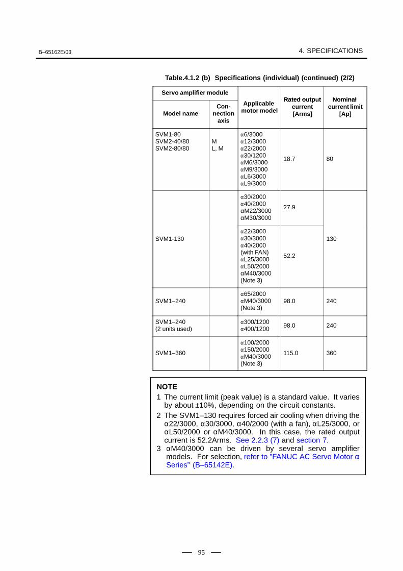
B–65162E/03 4. SPECIFICATIONS
95
Table.4.1.2 (b) Specifications (individual) (continued) (2/2)
Servo amplifier moduleRated o tp t Nominal
Model nameCon-
nectionaxis
Applicable motor model
Rated outputcurrent[Arms]
Nominal current limit
[Ap]
SVM1-80SVM2-40/80SVM2-80/80
ML, M
α6/3000α12/3000α22/2000α30/1200αM6/3000αM9/3000αL6/3000αL9/3000
18.7 80
α30/2000α40/2000αM22/3000αM30/3000
27.9
SVM1-130α22/3000α30/3000α40/2000(with FAN)αL25/3000αL50/2000αM40/3000(Note 3)
52.2
130
SVM1–240α65/2000αM40/3000(Note 3)
98.0 240
SVM1–240 (2 units used)
α300/1200α400/1200 98.0 240
SVM1–360
α100/2000α150/2000αM40/3000(Note 3)
115.0 360
NOTE1 The current limit (peak value) is a standard value. It varies
by about ±10%, depending on the circuit constants.2 The SVM1–130 requires forced air cooling when driving the
α22/3000, α30/3000, α40/2000 (with a fan), αL25/3000, orαL50/2000 or αM40/3000. In this case, the rated outputcurrent is 52.2Arms. See 2.2.3 (7) and section 7.
3 αM40/3000 can be driven by several servo amplifiermodels. For selection, refer to ”FANUC AC Servo Motor αSeries” (B–65142E).
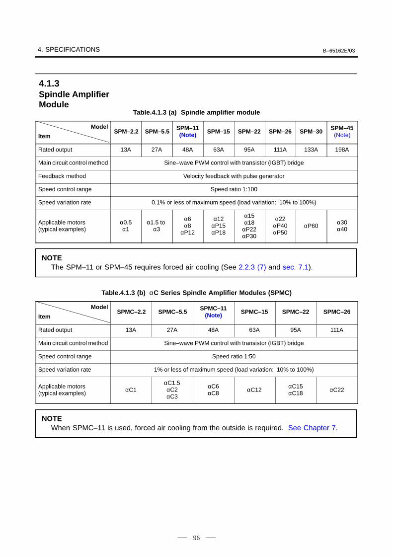
4. SPECIFICATIONS B–65162E/03
96
Table.4.1.3 (a) Spindle amplifier module
Model
ItemSPM–2.2 SPM–5.5 SPM–11
(Note) SPM–15 SPM–22 SPM–26 SPM–30 SPM–45(Note)
Rated output 13A 27A 48A 63A 95A 111A 133A 198A
Main circuit control method Sine–wave PWM control with transistor (IGBT) bridge
Feedback method Velocity feedback with pulse generator
Speed control range Speed ratio 1:100
Speed variation rate 0.1% or less of maximum speed (load variation: 10% to 100%)
Applicable motors (typical examples)
α0.5α1
α1.5 to α3
α6α8
αP12
α12αP15αP18
α15α18
αP22αP30
α22αP40αP50
αP60α30α40
NOTEThe SPM–11 or SPM–45 requires forced air cooling (See 2.2.3 (7) and sec. 7.1).
Table.4.1.3 (b) αC Series Spindle Amplifier Modules (SPMC)
Model
ItemSPMC–2.2 SPMC–5.5 SPMC–11
(Note) SPMC–15 SPMC–22 SPMC–26
Rated output 13A 27A 48A 63A 95A 111A
Main circuit control method Sine–wave PWM control with transistor (IGBT) bridge
Speed control range Speed ratio 1:50
Speed variation rate 1% or less of maximum speed (load variation: 10% to 100%)
Applicable motors (typical examples) αC1
αC1.5αC2αC3
αC6αC8 αC12
αC15αC18 αC22
NOTEWhen SPMC–11 is used, forced air cooling from the outside is required. See Chapter 7.
4.1.3Spindle AmplifierModule
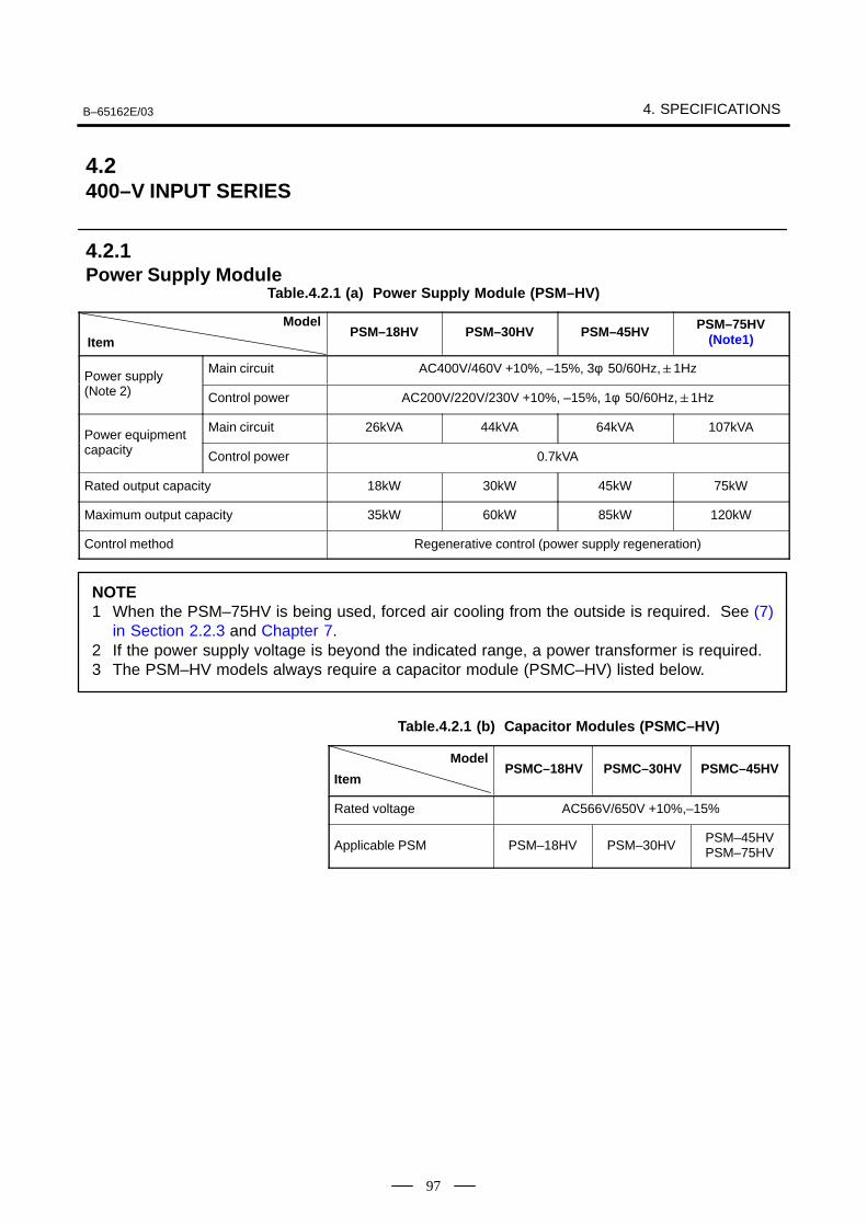
B–65162E/03 4. SPECIFICATIONS
97
Table.4.2.1 (a) Power Supply Module (PSM–HV)
Model
ItemPSM–18HV PSM–30HV PSM–45HV PSM–75HV
(Note1)
Power supply Main circuit AC400V/460V +10%, –15%, 3φ 50/60Hz,1Hz
Power su ly (Note 2) Control power AC200V/220V/230V +10%, –15%, 1φ 50/60Hz,1Hz
Power equipment Main circuit 26kVA 44kVA 64kVA 107kVA
Power equi ment capacity Control power 0.7kVA
Rated output capacity 18kW 30kW 45kW 75kW
Maximum output capacity 35kW 60kW 85kW 120kW
Control method Regenerative control (power supply regeneration)
NOTE1 When the PSM–75HV is being used, forced air cooling from the outside is required. See (7)
in Section 2.2.3 and Chapter 7.2 If the power supply voltage is beyond the indicated range, a power transformer is required.3 The PSM–HV models always require a capacitor module (PSMC–HV) listed below.
Table.4.2.1 (b) Capacitor Modules (PSMC–HV)
Model
ItemPSMC–18HV PSMC–30HV PSMC–45HV
Rated voltage AC566V/650V +10%,–15%
Applicable PSM PSM–18HV PSM–30HVPSM–45HVPSM–75HV
4.2400–V INPUT SERIES
4.2.1Power Supply Module
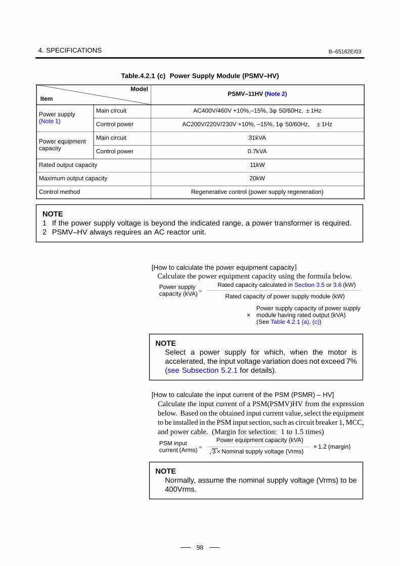
4. SPECIFICATIONS B–65162E/03
98
Table.4.2.1 (c) Power Supply Module (PSMV–HV)
Model
ItemPSMV–11HV (Note 2)
Power supply Main circuit AC400V/460V +10%,–15%, 3φ 50/60Hz, 1Hz
Power su ly (Note 1) Control power AC200V/220V/230V +10%, –15%, 1φ 50/60Hz, 1Hz
Power equipment Main circuit 31kVA
Power equi ment capacity Control power 0.7kVA
Rated output capacity 11kW
Maximum output capacity 20kW
Control method Regenerative control (power supply regeneration)
NOTE1 If the power supply voltage is beyond the indicated range, a power transformer is required.2 PSMV–HV always requires an AC reactor unit.
[How to calculate the power equipment capacity] Calculate the power equipment capacity using the formula below.
Power supplycapacity (kVA)
Rated capacity calculated in Section 3.5 or 3.6 (kW)
Rated capacity of power supply module (kW) =
×Power supply capacity of power supplymodule having rated output (kVA)(See Table 4.2.1 (a), (c))
NOTESelect a power supply for which, when the motor isaccelerated, the input voltage variation does not exceed 7%(see Subsection 5.2.1 for details).
[How to calculate the input current of the PSM (PSMR) – HV]Calculate the input current of a PSM(PSMV)HV from the expressionbelow. Based on the obtained input current value, select the equipmentto be installed in the PSM input section, such as circuit breaker 1, MCC,and power cable. (Margin for selection: 1 to 1.5 times)
PSM input current (Arms)
Power equipment capacity (kVA)
3Nominal supply voltage (Vrms) = × 1.2 (margin)
NOTENormally, assume the nominal supply voltage (Vrms) to be400Vrms.
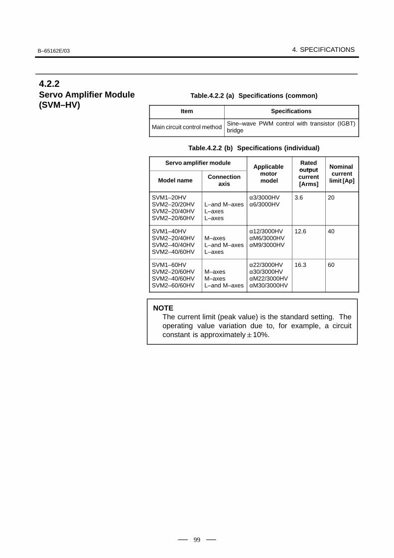
B–65162E/03 4. SPECIFICATIONS
99
Table.4.2.2 (a) Specifications (common)
Item Specifications
Main circuit control methodSine–wave PWM control with transistor (IGBT)bridge
Table.4.2.2 (b) Specifications (individual)
Servo amplifier moduleApplicable
Ratedo tp t Nominal
Model name Connectionaxis
Applicable motor model
outputcurrent[Arms]
Nominal current
limit [Ap]
SVM1–20HVSVM2–20/20HVSVM2–20/40HVSVM2–20/60HV
L–and M–axesL–axesL–axes
α3/3000HVα6/3000HV
3.6 20
SVM1–40HVSVM2–20/40HVSVM2–40/40HVSVM2–40/60HV
M–axesL–and M–axesL–axes
α12/3000HVαM6/3000HVαM9/3000HV
12.6 40
SVM1–60HVSVM2–20/60HVSVM2–40/60HVSVM2–60/60HV
M–axesM–axesL–and M–axes
α22/3000HVα30/3000HVαM22/3000HVαM30/3000HV
16.3 60
NOTEThe current limit (peak value) is the standard setting. Theoperating value variation due to, for example, a circuitconstant is approximately10%.
4.2.2Servo Amplifier Module(SVM–HV)
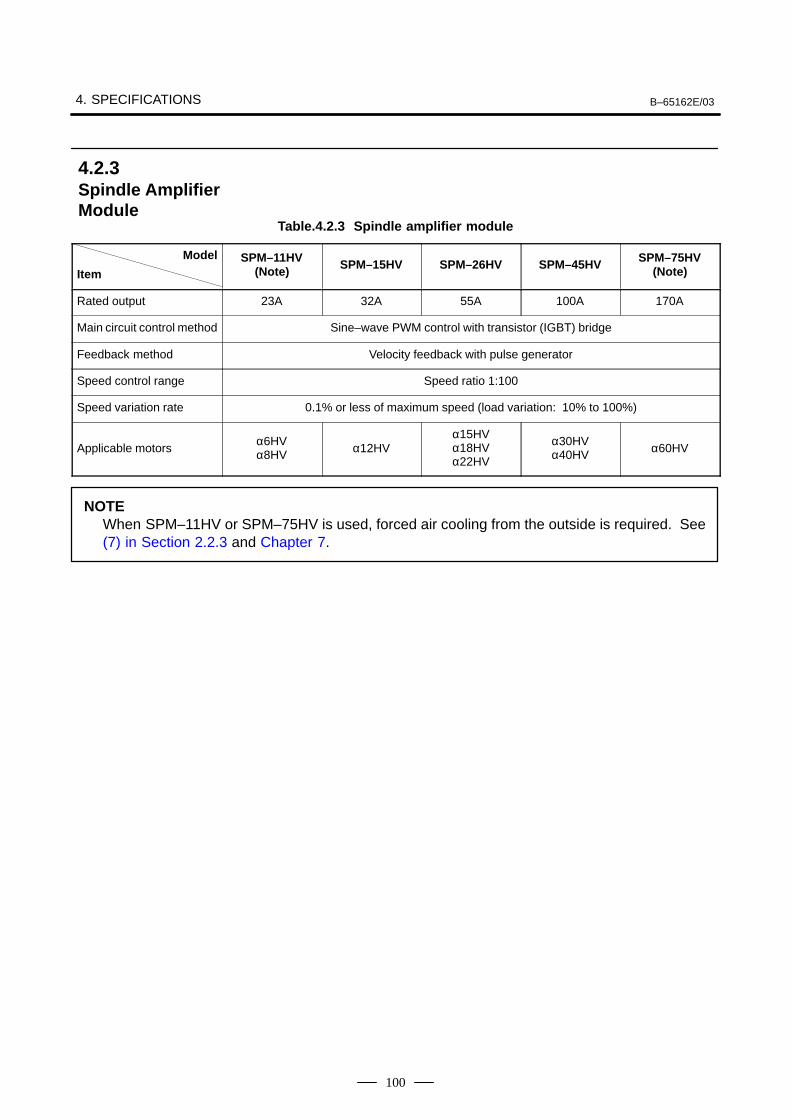
4. SPECIFICATIONS B–65162E/03
100
Table.4.2.3 Spindle amplifier module
Model
ItemSPM–11HV
(Note) SPM–15HV SPM–26HV SPM–45HV SPM–75HV(Note)
Rated output 23A 32A 55A 100A 170A
Main circuit control method Sine–wave PWM control with transistor (IGBT) bridge
Feedback method Velocity feedback with pulse generator
Speed control range Speed ratio 1:100
Speed variation rate 0.1% or less of maximum speed (load variation: 10% to 100%)
Applicable motorsα6HVα8HV α12HV
α15HVα18HVα22HV
α30HVα40HV α60HV
NOTEWhen SPM–11HV or SPM–75HV is used, forced air cooling from the outside is required. See(7) in Section 2.2.3 and Chapter 7.
4.2.3Spindle AmplifierModule
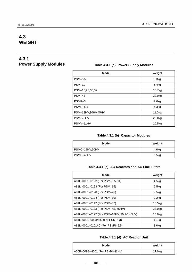
B–65162E/03 4. SPECIFICATIONS
101
Table.4.3.1 (a) Power Supply Modules
Model Weight
PSM–5.5 6.3kg
PSM–11 5.4kg
PSM–15,26,30,37 10.7kg
PSM–45 22.0kg
PSMR–3 2.6kg
PSMR–5.5 4.3kg
PSM–18HV,30HV,45HV 11.0kg
PSM–75HV 22.0kg
PSMV–11HV 10.5kg
Table.4.3.1 (b) Capacitor Modules
Model Weight
PSMC–18HV,30HV 4.0kg
PSMC–45HV 6.5kg
Table.4.3.1 (c) AC Reactors and AC Line Filters
Model Weight
A81L–0001–0122 (For PSM–5.5, 11) 4.5kg
A81L–0001–0123 (For PSM–15) 6.5kg
A81L–0001–0120 (For PSM–26) 9.5kg
A81L–0001–0124 (For PSM–30) 9.2kg
A81L–0001–0147 (For PSM–37) 16.5kg
A81L–0001–0133 (For PSM–45, 75HV) 38.0kg
A81L–0001–0127 (For PSM–18HV, 30HV, 45HV) 15.0kg
A81L–0001–0083#3C (For PSMR–3) 1.1kg
A81L–0001–0101#C (For PSMR–5.5) 3.0kg
Table.4.3.1 (d) AC Reactor Unit
Model Weight
A06B–6098–H001 (For PSMV–11HV) 17.0kg
4.3WEIGHT
4.3.1Power Supply Modules
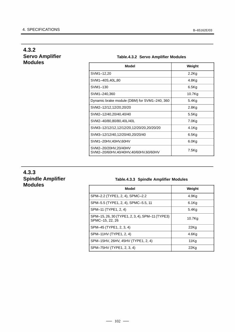
4. SPECIFICATIONS B–65162E/03
102
Table.4.3.2 Servo Amplifier Modules
Model Weight
SVM1–12,20 2.2Kg
SVM1–40S,40L,80 4.8Kg
SVM1–130 6.5Kg
SVM1–240,360 10.7Kg
Dynamic brake module (DBM) for SVM1–240, 360 5.4Kg
SVM2–12/12,12/20,20/20 2.8Kg
SVM2–12/40,20/40,40/40 5.5Kg
SVM2–40/80,80/80,40L/40L 7.0Kg
SVM3–12/12/12,12/12/20,12/20/20,20/20/20 4.1Kg
SVM3–12/12/40,12/20/40,20/20/40 6.5Kg
SVM1–20HV,40HV,60HV 6.0Kg
SVM2–20/20HV,20/40HVSVM2–20/60HV,40/40HV,40/60HV,60/60HV 7.5Kg
Table.4.3.3 Spindle Amplifier Modules
Model Weight
SPM–2.2 (TYPE1, 2, 4), SPMC–2.2 4.9Kg
SPM–5.5 (TYPE1, 2, 4), SPMC–5.5, 11 6.1Kg
SPM–11 (TYPE1, 2, 4) 5.4Kg
SPM–15, 26, 30 (TYPE1, 2, 3, 4), SPM–11 (TYPE3)SPMC–15, 22, 26 10.7Kg
SPM–45 (TYPE1, 2, 3, 4) 22Kg
SPM–11HV (TYPE1, 2, 4) 4.6Kg
SPM–15HV, 26HV, 45HV (TYPE1, 2, 4) 11Kg
SPM–75HV (TYPE1, 2, 3, 4) 22Kg
4.3.2Servo AmplifierModules
4.3.3Spindle AmplifierModules

B–65162E/03 5. INSTALLATION
103
5
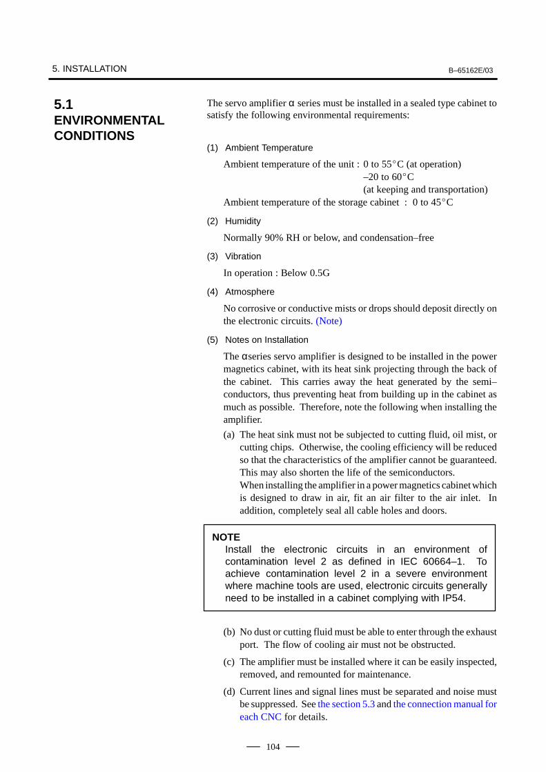
5. INSTALLATION B–65162E/03
104
The servo amplifier α series must be installed in a sealed type cabinet tosatisfy the following environmental requirements:
(1) Ambient Temperature
Ambient temperature of the unit : 0 to 55C (at operation)–20 to 60C(at keeping and transportation)
Ambient temperature of the storage cabinet : 0 to 45C
(2) Humidity
Normally 90% RH or below, and condensation–free
(3) Vibration
In operation : Below 0.5G
(4) Atmosphere
No corrosive or conductive mists or drops should deposit directly onthe electronic circuits. (Note)
(5) Notes on Installation
The αseries servo amplifier is designed to be installed in the powermagnetics cabinet, with its heat sink projecting through the back ofthe cabinet. This carries away the heat generated by the semi–conductors, thus preventing heat from building up in the cabinet asmuch as possible. Therefore, note the following when installing theamplifier.
(a) The heat sink must not be subjected to cutting fluid, oil mist, orcutting chips. Otherwise, the cooling efficiency will be reducedso that the characteristics of the amplifier cannot be guaranteed.This may also shorten the life of the semiconductors.When installing the amplifier in a power magnetics cabinet whichis designed to draw in air, fit an air filter to the air inlet. Inaddition, completely seal all cable holes and doors.
NOTEInstall the electronic circuits in an environment ofcontamination level 2 as defined in IEC 60664–1. Toachieve contamination level 2 in a severe environmentwhere machine tools are used, electronic circuits generallyneed to be installed in a cabinet complying with IP54.
(b) No dust or cutting fluid must be able to enter through the exhaustport. The flow of cooling air must not be obstructed.
(c) The amplifier must be installed where it can be easily inspected,removed, and remounted for maintenance.
(d) Current lines and signal lines must be separated and noise mustbe suppressed. See the section 5.3 and the connection manual foreach CNC for details.
5.1ENVIRONMENTALCONDITIONS
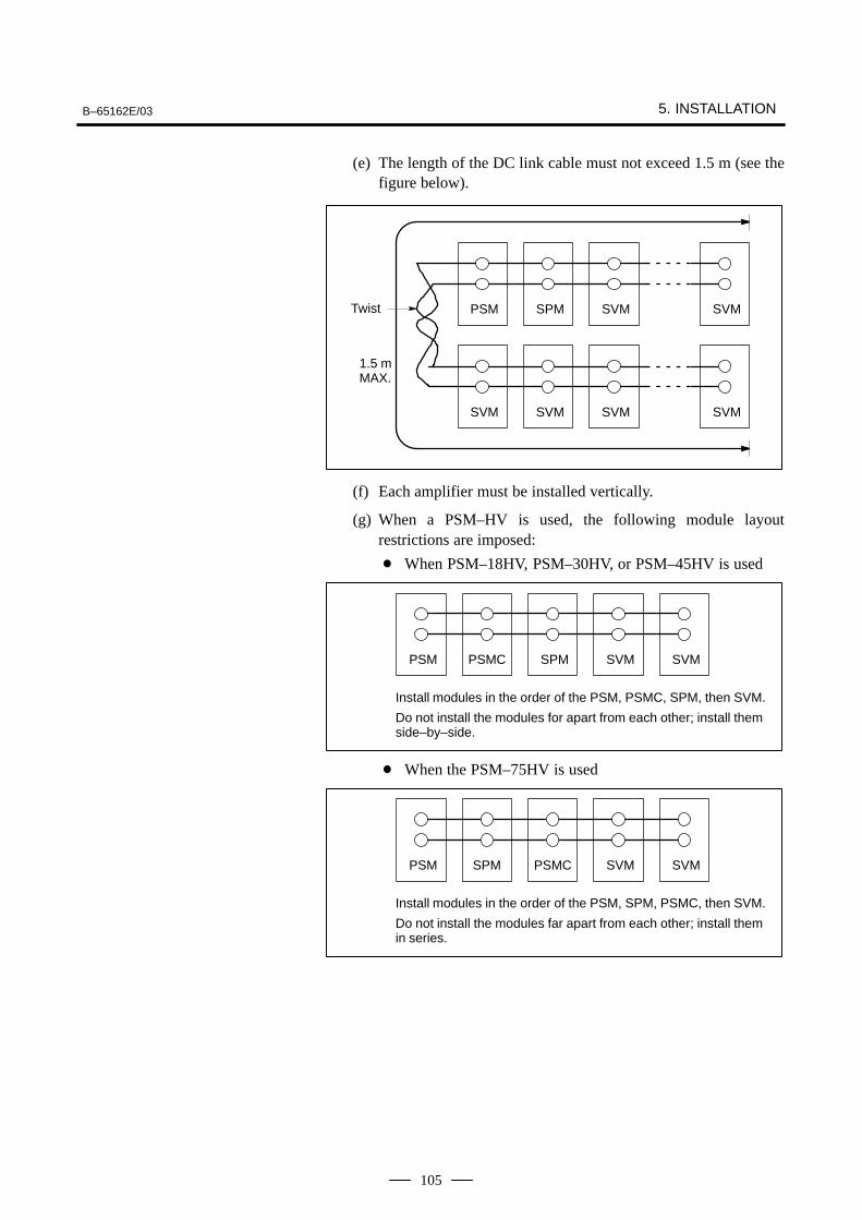
B–65162E/03 5. INSTALLATION
105
(e) The length of the DC link cable must not exceed 1.5 m (see thefigure below).
PSM SPM SVM SVM
SVM SVM SVM SVM
ÃÃ
ÃÃÃÃ
ÃÃÃÃ
ÃÃÃÃ
ÃÃÃÃ
ÃÃÃÃÃÃÃÃ
ÃÃÃÃÃÃÃÃ
ÃÃÃÃÃÃÃÃ
Twist
1.5 mMAX.
(f) Each amplifier must be installed vertically.
(g) When a PSM–HV is used, the following module layoutrestrictions are imposed:
When PSM–18HV, PSM–30HV, or PSM–45HV is used
PSM PSMC SPM
ÃÃÃÃ
ÃÃÃÃ
ÃÃÃÃ
SVM
ÃÃÃÃ
SVM
ÃÃÃÃÃÃÃÃ
Install modules in the order of the PSM, PSMC, SPM, then SVM.
Do not install the modules for apart from each other; install themside–by–side.
When the PSM–75HV is used
PSM SPM PSMC
ÃÃÃÃ
ÃÃÃÃ
ÃÃÃÃ
SVM
ÃÃÃÃ
SVM
ÃÃÃÃÃÃÃÃ
Install modules in the order of the PSM, SPM, PSMC, then SVM.
Do not install the modules far apart from each other; install themin series.
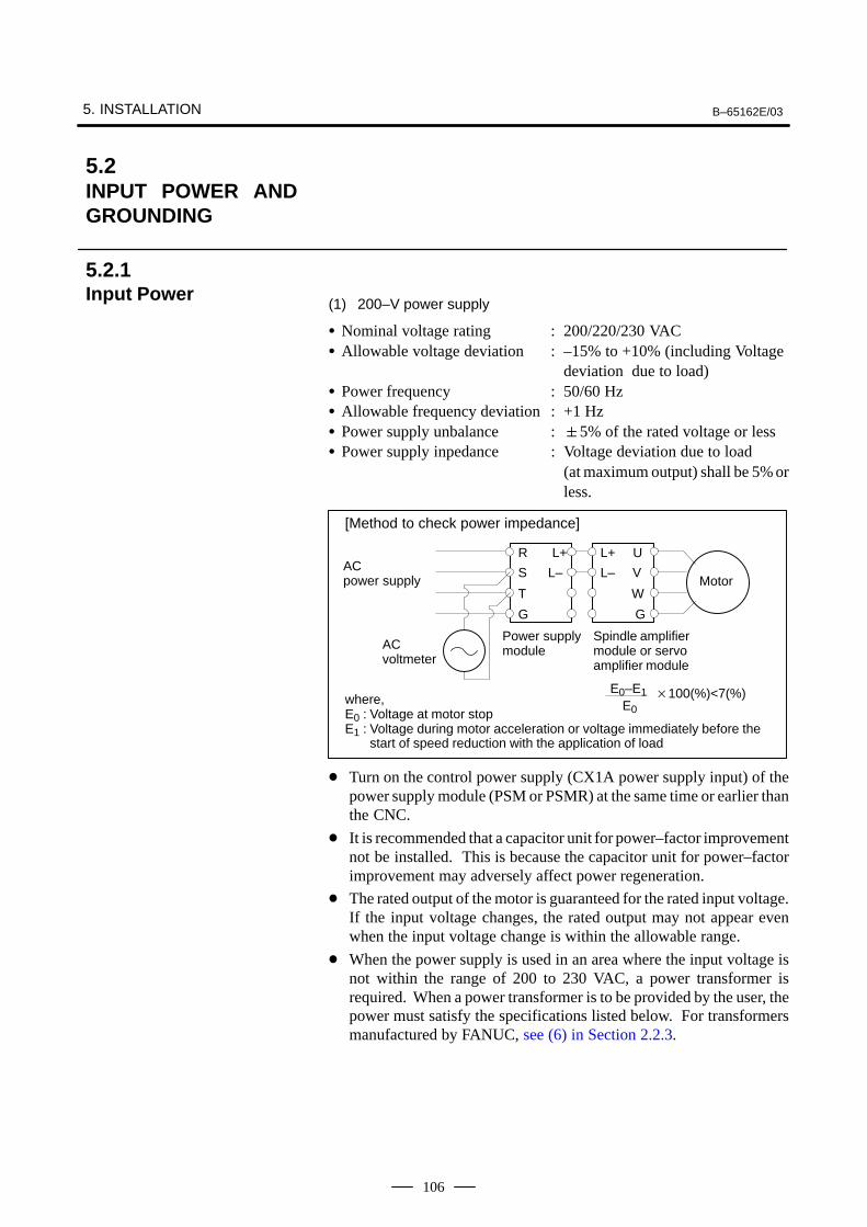
5. INSTALLATION B–65162E/03
106
(1) 200–V power supply
Nominal voltage rating : 200/220/230 VAC Allowable voltage deviation : –15% to +10% (including Voltage
deviation due to load) Power frequency : 50/60 Hz Allowable frequency deviation : +1 Hz Power supply unbalance :5% of the rated voltage or less Power supply inpedance : Voltage deviation due to load
(at maximum output) shall be 5% orless.
AC power supply
[Method to check power impedance]
where, E0 : Voltage at motor stopE1 : Voltage during motor acceleration or voltage immediately before the
start of speed reduction with the application of load
ÃÃÃÃÃÃ
ÃÃÃÃÃÃÃÃÃÃÃÃÃÃ
R L+
S L–
T
G
Motor
E0–E1E0
100(%)<7(%)
ÃÃÃÃÃÃÃÃÃÃÃÃÃÃ
ÃÃÃÃÃÃÃ
L+ U
L– V
W
G
AC voltmeter
Power supplymodule
Spindle amplifiermodule or servoamplifier module
Turn on the control power supply (CX1A power supply input) of thepower supply module (PSM or PSMR) at the same time or earlier thanthe CNC.
It is recommended that a capacitor unit for power–factor improvementnot be installed. This is because the capacitor unit for power–factorimprovement may adversely affect power regeneration.
The rated output of the motor is guaranteed for the rated input voltage.If the input voltage changes, the rated output may not appear evenwhen the input voltage change is within the allowable range.
When the power supply is used in an area where the input voltage isnot within the range of 200 to 230 VAC, a power transformer isrequired. When a power transformer is to be provided by the user, thepower must satisfy the specifications listed below. For transformersmanufactured by FANUC, see (6) in Section 2.2.3.
5.2INPUT POWER ANDGROUNDING
5.2.1Input Power

B–65162E/03 5. INSTALLATION
107
Table.5.2.1 Transformer Specifications
PSMR–3(2 kW
output)
PSMR–3(3 kW
output)
PSM–5.5PSMR–5.5
(5.5 kWoutput)
PSM–11PSMR–5.5
(7.5 kWoutput)
PSM–15 PSM–26 PSM–30 PSM–37PSM–45
Rated capacity kVA 3.5 5 9 17 22 37 44 64
Secondary current A 10 14 26 48 62 105 130 185
Secondary output voltage 200V
Secondary voltage regulation 5%
Secondary voltage deviation 3%
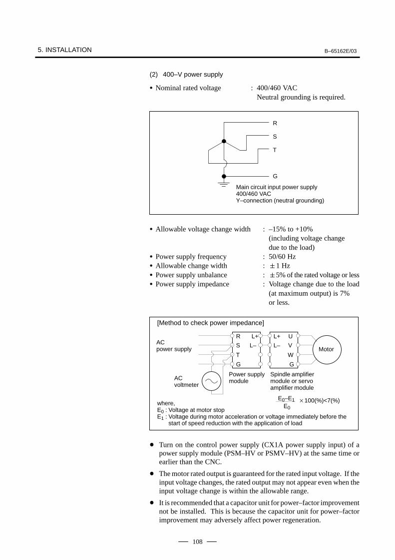
5. INSTALLATION B–65162E/03
108
(2) 400–V power supply
Nominal rated voltage : 400/460 VAC Neutral grounding is required.
R
S
T
G
Main circuit input power supply400/460 VACY–connection (neutral grounding)
Allowable voltage change width : –15% to +10% (including voltage change due to the load)
Power supply frequency : 50/60 Hz Allowable change width :1 Hz Power supply unbalance :5% of the rated voltage or less Power supply impedance : Voltage change due to the load
(at maximum output) is 7% or less.
AC power supply
[Method to check power impedance]
where, E0 : Voltage at motor stopE1 : Voltage during motor acceleration or voltage immediately before the
start of speed reduction with the application of load
ÃÃÃÃÃÃ
ÃÃÃÃÃÃÃÃÃÃÃÃ
R L+
S L–
T
G
Motor
E0–E1E0
100(%)<7(%)
ÃÃÃÃÃÃÃÃÃÃÃÃ
ÃÃÃÃÃÃ
L+ U
L– V
W
G
AC voltmeter
Power supplymodule
Spindle amplifiermodule or servoamplifier module
Turn on the control power supply (CX1A power supply input) of apower supply module (PSM–HV or PSMV–HV) at the same time orearlier than the CNC.
The motor rated output is guaranteed for the rated input voltage. If theinput voltage changes, the rated output may not appear even when theinput voltage change is within the allowable range.
It is recommended that a capacitor unit for power–factor improvementnot be installed. This is because the capacitor unit for power–factorimprovement may adversely affect power regeneration.
B–65162E/03 5. INSTALLATION
109
The servo amplifier α series drives the motor by using the transistorPWM inverter method. This causes a high–frequency leakage current toflow via the ground drift capacitance in the motor winding, power cable,and amplifier. This may cause a device installed on the power supply side,such as a ground fault interrupter or leakage–protection relay, tomalfunction.
When a circuit breaker with a ground fault interrupter is used, it must beselected so that the sum of the values calculated according to (a) and (b)described below is not greater than the non–operating current value.
(a) Selection criterion per amplifier
Model : SVM and SPM (both except the HV series)(NOTE 1), SPMC
Criterion for selection: 2 mA per amplifier (NOTE 2)
(b) Selection criterion per motor
Criterion for selection: 1 mA per motor (NOTE 2)The following example shows how to use selection criteria (a) and (b):Example : When the system consists of SMV11,
SVM31 (three motors), and SPM12 mA3 (for the amplifiers) + 1 mA5 (for the motors) = 11 mA→ Select a circuit breaker (NOTE 3) with a non–operatingcurrent of 11 mA or higher. (A general ground faultinterrupter that can be used for the above example is the onewith a rated sensitivity current of 30 mA and a non–operatingcurrent of 15 mA.)
NOTE1 In the 400–V input series, the power supply is grounded by
neutral grounding, so there is no leakage current that wouldcause a circuit breaker with a ground fault interrupter,connected on the power supply side, to malfunction.
2 These criteria are for selecting a circuit breaker with aground fault interrupter; they do not indicate accurateleakage currents.
3 A circuit breaker may malfunction depending on thefrequency characteristic of the ground fault interrupter.Therefore, use a ground fault interrupter supporting the useof inverters.
4 The above criteria are values in the commercial frequencyband. Some measuring instruments for measuring leakagecurrent may sense a high frequency band, thus showing alarger value.
5.2.2Leakage Current
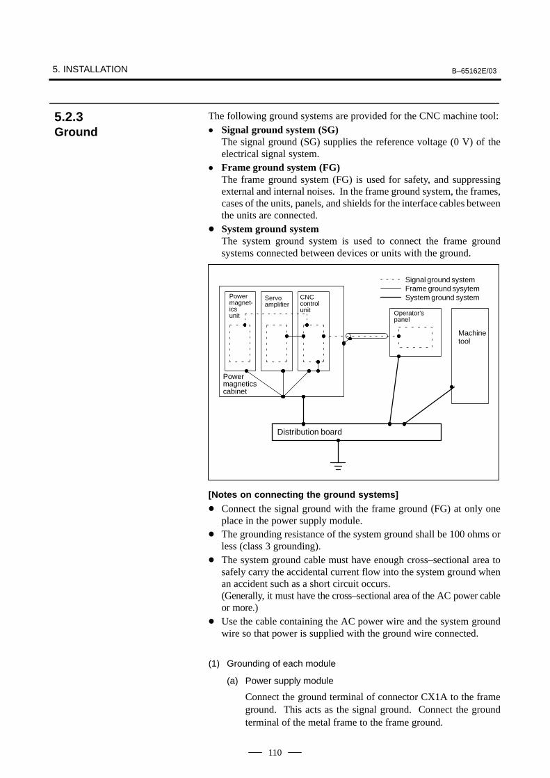
5. INSTALLATION B–65162E/03
110
The following ground systems are provided for the CNC machine tool: Signal ground system (SG)
The signal ground (SG) supplies the reference voltage (0 V) of theelectrical signal system.
Frame ground system (FG)The frame ground system (FG) is used for safety, and suppressingexternal and internal noises. In the frame ground system, the frames,cases of the units, panels, and shields for the interface cables betweenthe units are connected.
System ground systemThe system ground system is used to connect the frame groundsystems connected between devices or units with the ground.
Power magnet-ics unit
Servoamplifier
CNCcontrol unit
Powermagneticscabinet
Distribution board
Operator’spanel
Machinetool
System ground systemFrame ground sysytemSignal ground system
[Notes on connecting the ground systems]
Connect the signal ground with the frame ground (FG) at only oneplace in the power supply module.
The grounding resistance of the system ground shall be 100 ohms orless (class 3 grounding).
The system ground cable must have enough cross–sectional area tosafely carry the accidental current flow into the system ground whenan accident such as a short circuit occurs.(Generally, it must have the cross–sectional area of the AC power cableor more.)
Use the cable containing the AC power wire and the system groundwire so that power is supplied with the ground wire connected.
(1) Grounding of each module
(a) Power supply module
Connect the ground terminal of connector CX1A to the frameground. This acts as the signal ground. Connect the groundterminal of the metal frame to the frame ground.
5.2.3Ground
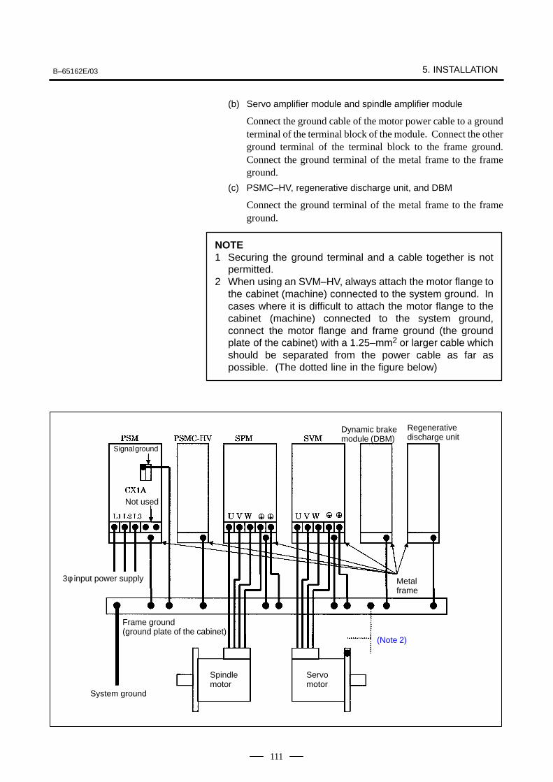
B–65162E/03 5. INSTALLATION
111
(b) Servo amplifier module and spindle amplifier module
Connect the ground cable of the motor power cable to a groundterminal of the terminal block of the module. Connect the otherground terminal of the terminal block to the frame ground.Connect the ground terminal of the metal frame to the frameground.
(c) PSMC–HV, regenerative discharge unit, and DBM
Connect the ground terminal of the metal frame to the frameground.
NOTE1 Securing the ground terminal and a cable together is not
permitted.2 When using an SVM–HV, always attach the motor flange to
the cabinet (machine) connected to the system ground. Incases where it is difficult to attach the motor flange to thecabinet (machine) connected to the system ground,connect the motor flange and frame ground (the groundplate of the cabinet) with a 1.25–mm2 or larger cable whichshould be separated from the power cable as far aspossible. (The dotted line in the figure below)
Signal ground
Not used
3φ input power supply
Dynamic brakemodule (DBM)
Regenerativedischarge unit
Metalframe
Frame ground (ground plate of the cabinet)
System ground
Spindlemotor
Servomotor
(Note 2)
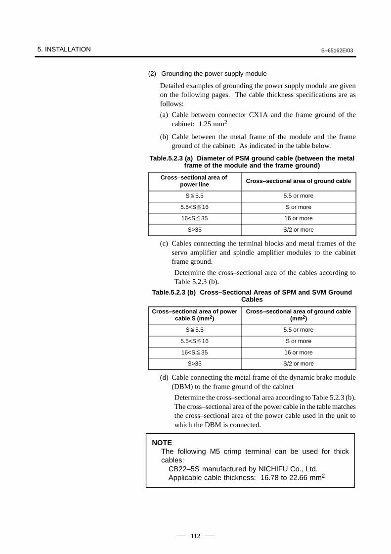
5. INSTALLATION B–65162E/03
112
(2) Grounding the power supply module
Detailed examples of grounding the power supply module are givenon the following pages. The cable thickness specifications are asfollows:
(a) Cable between connector CX1A and the frame ground of thecabinet: 1.25 mm2
(b) Cable between the metal frame of the module and the frameground of the cabinet: As indicated in the table below.
Table.5.2.3 (a) Diameter of PSM ground cable (between the metalframe of the module and the frame ground)
Cross–sectional area of power line Cross–sectional area of ground cable
S5.5 5.5 or more
5.5<S16 S or more
16<S35 16 or more
S>35 S/2 or more
(c) Cables connecting the terminal blocks and metal frames of theservo amplifier and spindle amplifier modules to the cabinetframe ground.
Determine the cross–sectional area of the cables according toTable 5.2.3 (b).
Table.5.2.3 (b) Cross–Sectional Areas of SPM and SVM GroundCables
Cross–sectional area of powercable S (mm 2)
Cross–sectional area of ground cable(mm2)
S5.5 5.5 or more
5.5<S16 S or more
16<S35 16 or more
S>35 S/2 or more
(d) Cable connecting the metal frame of the dynamic brake module(DBM) to the frame ground of the cabinet
Determine the cross–sectional area according to Table 5.2.3 (b).The cross–sectional area of the power cable in the table matchesthe cross–sectional area of the power cable used in the unit towhich the DBM is connected.
NOTEThe following M5 crimp terminal can be used for thickcables:
CB22–5S manufactured by NICHIFU Co., Ltd.Applicable cable thickness: 16.78 to 22.66 mm2
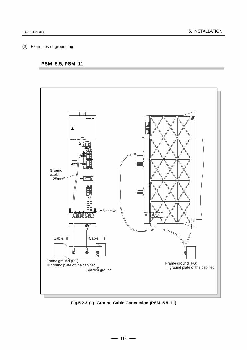
B–65162E/03 5. INSTALLATION
113
(3) Examples of grounding
PSM–5.5, PSM–11
ÃÃÃÃÃSystem ground
ÃÃÃÃÃÃÃÃÃÃÃÃÃÃÃÃÃÃÃÃÃÃÃÃÃÃÃ
Frame ground (FG) = ground plate of the cabinet ÃÃÃÃÃÃÃÃÃ
ÃÃÃÃÃÃÃÃÃFrame ground (FG) = ground plate of the cabinet
Cable Cable
ÃÃÃÃM5 screw
ÃÃÃÃÃÃÃÃ
Groundcable1.25mm2
Fig.5.2.3 (a) Ground Cable Connection (PSM–5.5, 11)
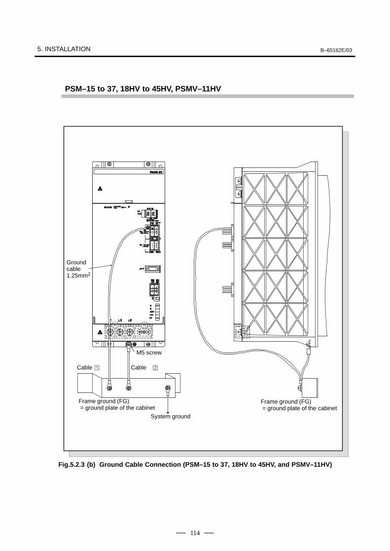
5. INSTALLATION B–65162E/03
114
PSM–15 to 37, 18HV to 45HV, PSMV–11HV
Groundcable1.25mm2
ÃÃÃÃÃÃÃÃÃÃÃÃÃÃÃÃÃÃ
Frame ground (FG) = ground plate of the cabinet
System ground
ÃÃÃÃÃÃÃÃÃÃÃÃÃÃÃÃÃÃ
Frame ground (FG) = ground plate of the cabinet
Cable Cable
M5 screw
Fig.5.2.3 (b) Ground Cable Connection (PSM–15 to 37, 18HV to 45HV, and PSMV–11HV)
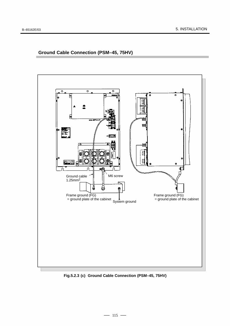
B–65162E/03 5. INSTALLATION
115
Ground Cable Connection (PSM–45, 75HV)
M5 screw
ÃÃÃÃÃÃÃÃÃÃÃÃÃÃÃÃÃÃ
Frame ground (FG) = ground plate of the cabinet
ÃÃÃÃÃÃSystem groundÃÃÃÃÃÃÃÃÃÃÃÃÃÃÃÃÃÃ
Frame ground (FG) = ground plate of the cabinet
ÃÃÃÃÃÃÃÃÃÃÃÃÃÃÃ
Ground cable1.25mm2
ÃÃÃÃÃÃÃÃÃÃ
M6 screw
Fig.5.2.3 (c) Ground Cable Connection (PSM–45, 75HV)
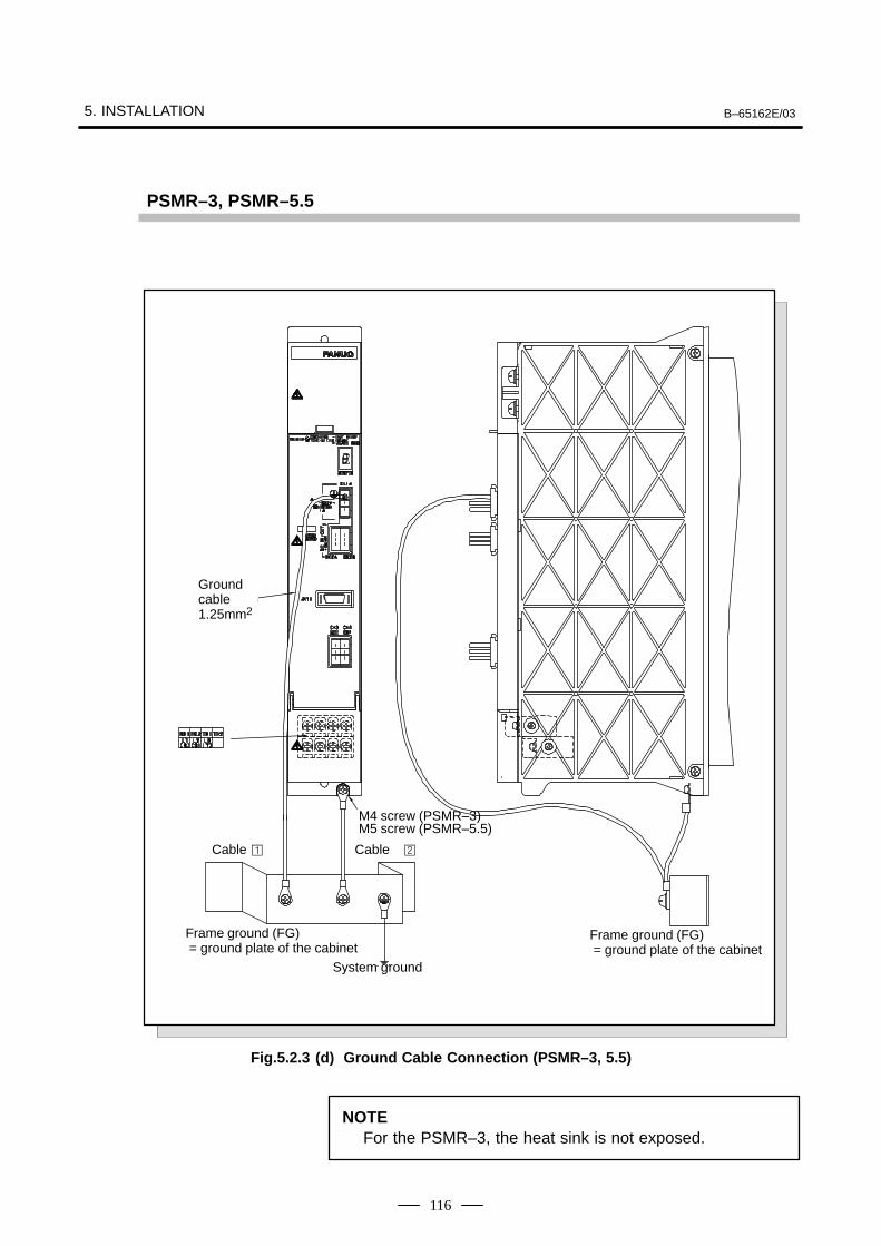
5. INSTALLATION B–65162E/03
116
PSMR–3, PSMR–5.5
ÃÃÃÃÃÃÃÃ
Groundcable1.25mm2
ÃÃÃÃÃÃÃÃÃÃÃÃÃÃÃÃÃÃÃÃ
Frame ground (FG) = ground plate of the cabinet
ÃÃÃÃÃÃÃÃÃÃÃÃ
System ground
ÃÃÃÃÃÃÃÃÃÃÃÃÃÃÃÃÃÃ
Frame ground (FG) = ground plate of the cabinet
Cable Cable
M5 screw (PSMR–5.5)M4 screw (PSMR–3)
Fig.5.2.3 (d) Ground Cable Connection (PSMR–3, 5.5)
NOTEFor the PSMR–3, the heat sink is not exposed.
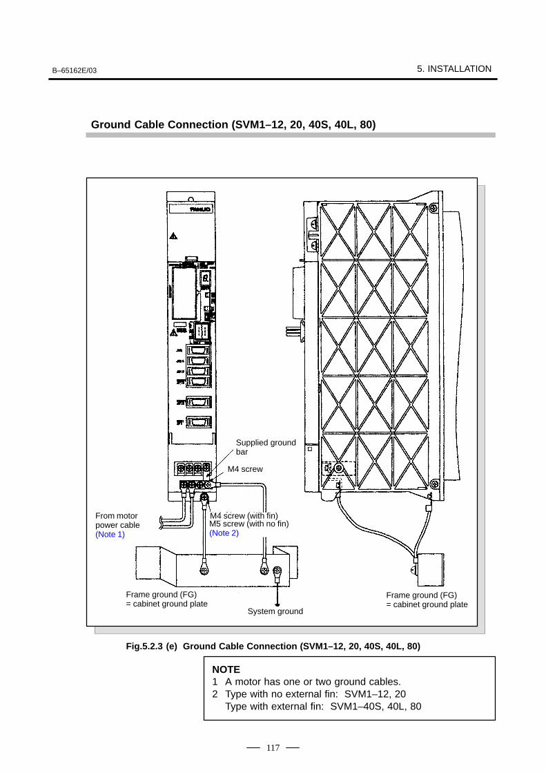
B–65162E/03 5. INSTALLATION
117
Ground Cable Connection (SVM1–12, 20, 40S, 40L, 80)
ÃÃÃÃÃÃÃÃÃÃÃÃÃÃÃ
From motorpower cable (Note 1)
ÃÃÃÃÃÃÃÃÃÃÃÃ
Supplied groundbar
ÃÃÃÃÃÃÃÃÃÃÃÃ
M4 screw (with fin)ÃÃÃÃÃÃÃÃÃÃÃÃÃÃÃÃÃÃÃÃ
M5 screw (with no fin) (Note 2)
ÃÃÃÃÃÃÃÃÃÃÃÃÃÃÃÃÃÃ
Frame ground (FG) = cabinet ground plate
ÃÃÃÃÃÃÃÃÃÃSystem ground
ÃÃÃÃÃÃÃÃ
M4 screw
ÃÃÃÃÃÃÃÃÃÃÃÃÃÃÃÃ
Frame ground (FG) = cabinet ground plate
Fig.5.2.3 (e) Ground Cable Connection (SVM1–12, 20, 40S, 40L, 80)
NOTE1 A motor has one or two ground cables.2 Type with no external fin: SVM1–12, 20
Type with external fin: SVM1–40S, 40L, 80

5. INSTALLATION B–65162E/03
118
Ground Cable Connection (SVM1–130, 20HV, 40HV, 60HV)
ÃÃÃÃÃÃÃÃÃÃ
From motorpower cable
ÃÃÃÃÃÃÃÃ
M4 screw
ÃÃÃÃÃÃÃÃ
M5 screw
ÃÃÃÃÃÃÃÃÃÃÃÃ
System ground
ÃÃÃÃÃÃÃÃÃÃÃÃÃÃÃÃÃÃÃÃÃÃ
Frame ground (FG) = cabinetground plate
ÃÃÃÃÃÃÃÃÃÃÃÃÃÃÃÃÃÃÃÃÃÃÃÃÃÃ
Frame ground (FG) = cabinet ground plate
Fig.5.2.3 (f) Ground Cable Connection (SVM1–130, 20HV, 40HV, 60HV)
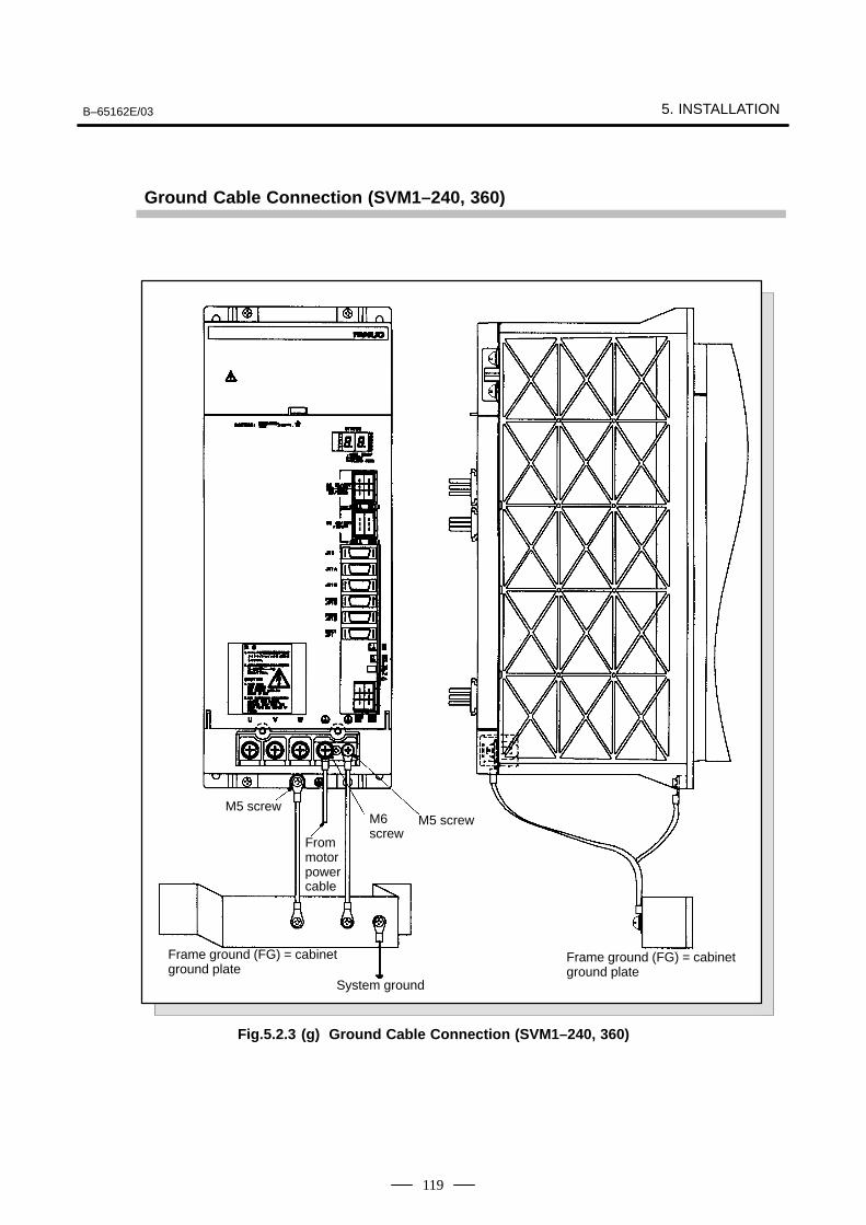
B–65162E/03 5. INSTALLATION
119
Ground Cable Connection (SVM1–240, 360)
ÃÃÃÃÃÃÃÃÃ
M6 screw
ÃÃÃÃÃÃÃÃ
M5 screw
ÃÃÃÃÃÃSystem ground
ÃÃÃÃÃÃÃÃÃÃÃÃÃÃÃÃÃÃÃÃÃÃÃÃÃÃÃÃÃÃ
Frame ground (FG) = cabinetground plate
ÃÃÃÃÃÃÃÃÃÃÃÃÃÃÃÃÃÃÃÃÃÃÃÃÃÃÃÃÃÃ
Frame ground (FG) = cabinetground plate
ÃÃÃÃM5 screw
From motor power cable
Fig.5.2.3 (g) Ground Cable Connection (SVM1–240, 360)
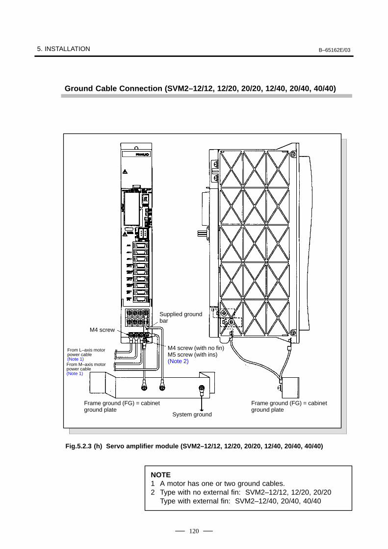
5. INSTALLATION B–65162E/03
120
Ground Cable Connection (SVM2–12/12, 12/20, 20/20, 12/40, 20/40, 40/40)
ÃÃÃÃÃÃÃÃÃÃÃÃ
Supplied groundbar
ÃÃÃÃM4 screw
ÃÃÃÃÃÃÃÃÃÃÃÃÃÃÃÃÃÃÃÃÃ
M4 screw (with no fin)M5 screw (with ins)(Note 2)
ÃÃÃÃÃÃÃÃÃÃÃÃ
System ground
ÃÃÃÃÃÃÃÃÃÃÃÃÃÃÃÃÃÃÃÃFrame ground (FG) = cabinetground plate
ÃÃÃÃÃÃÃÃÃÃÃÃÃÃÃÃÃÃ
Frame ground (FG) = cabinetground plate
From L–axis motor power cable (Note 1)From M–axis motor power cable (Note 1)
Fig.5.2.3 (h) Servo amplifier module (SVM2–12/12, 12/20, 20/20, 12/40, 20/40, 40/40)
NOTE1 A motor has one or two ground cables.2 Type with no external fin: SVM2–12/12, 12/20, 20/20
Type with external fin: SVM2–12/40, 20/40, 40/40
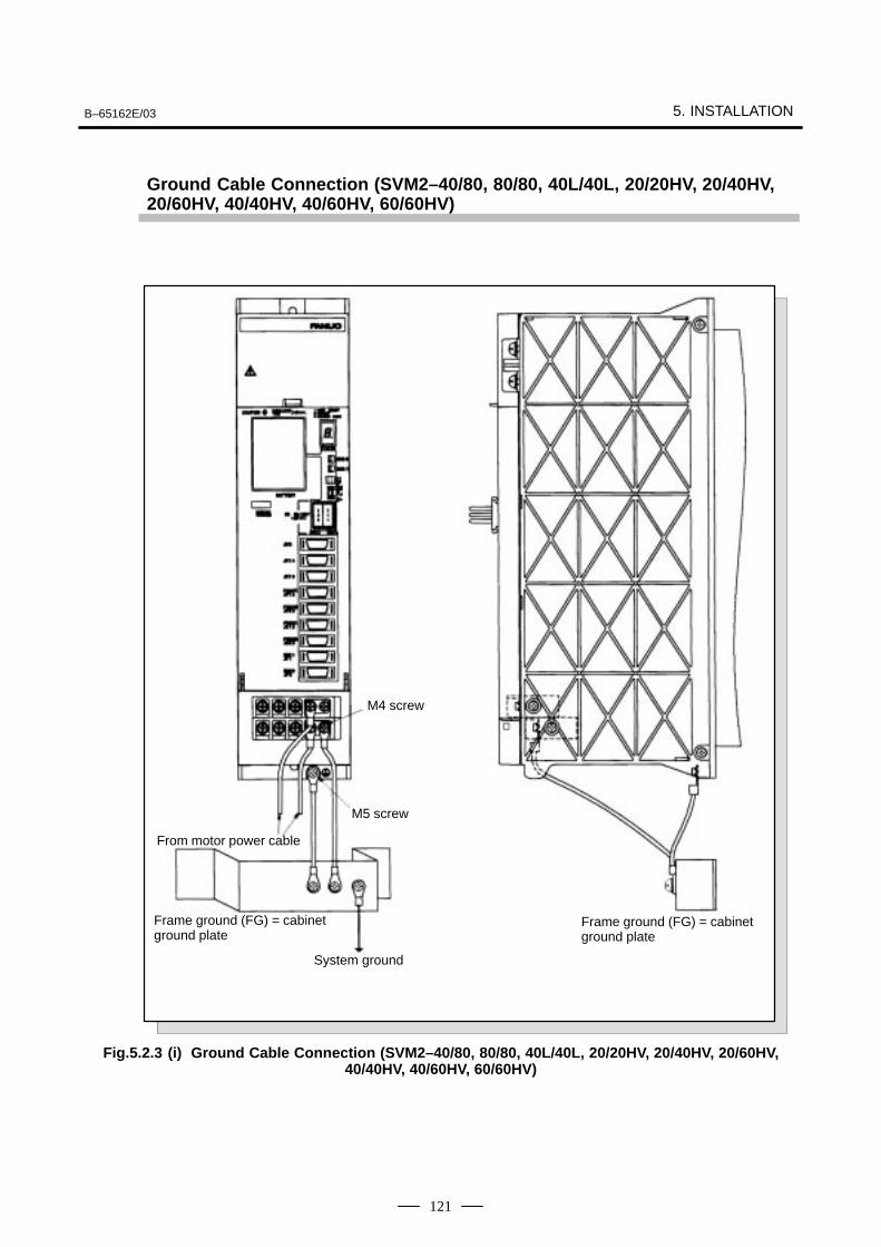
B–65162E/03 5. INSTALLATION
121
Ground Cable Connection (SVM2–40/80, 80/80, 40L/40L, 20/20HV, 20/40HV,20/60HV, 40/40HV, 40/60HV, 60/60HV)
ÃÃÃÃM4 screw
ÃÃÃÃÃÃM5 screw
ÃÃÃÃÃÃSystem ground
ÃÃÃÃÃÃÃÃÃÃÃÃÃÃÃÃÃÃ
Frame ground (FG) = cabinetground plate
ÃÃÃÃÃÃÃÃÃÃÃÃÃÃÃÃÃÃÃÃ
Frame ground (FG) = cabinetground plate
From motor power cable
Fig.5.2.3 (i) Ground Cable Connection (SVM2–40/80, 80/80, 40L/40L, 20/20HV, 20/40HV, 20/60HV,40/40HV, 40/60HV, 60/60HV)
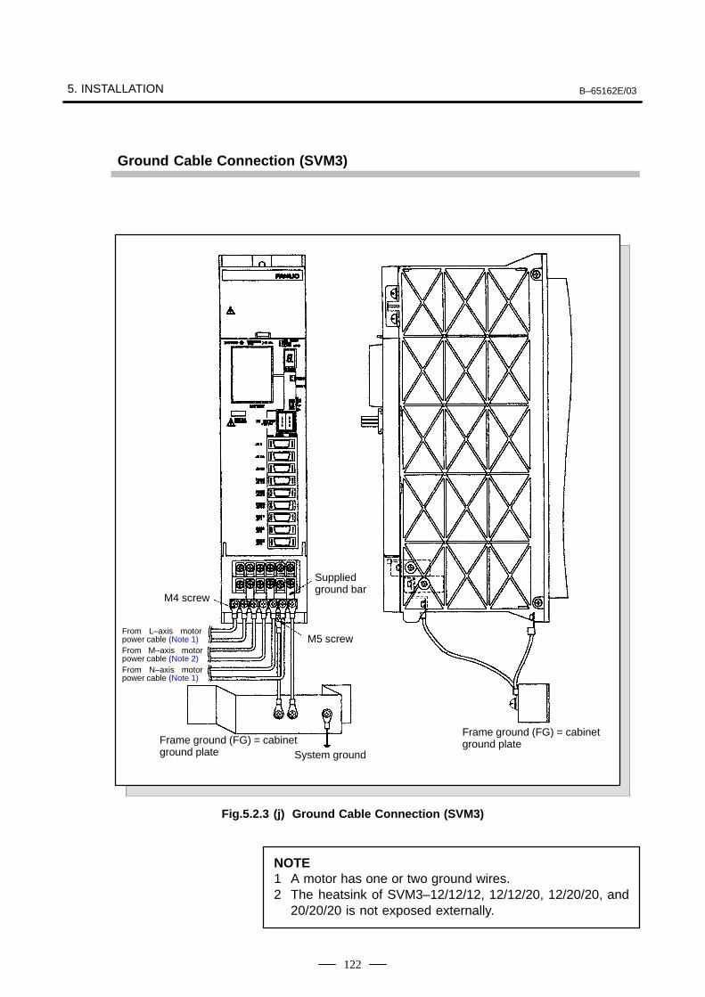
5. INSTALLATION B–65162E/03
122
Ground Cable Connection (SVM3)
ÃÃÃÃÃÃÃÃÃÃ
Supplied ground bar
ÃÃÃÃM4 screw
ÃÃÃÃM5 screw
ÃÃÃÃÃÃÃÃÃÃÃÃÃÃÃÃÃÃÃÃÃÃÃÃÃÃÃ
Frame ground (FG) = cabinetground plate
ÃÃÃÃÃÃÃÃÃÃÃÃÃÃÃÃÃÃÃÃ
Frame ground (FG) = cabinetground plate
ÃÃÃÃÃÃÃÃÃÃÃÃ
From L–axis motorpower cable (Note 1)
ÃÃÃÃÃÃFrom M–axis motorpower cable (Note 2)
ÃÃÃÃÃÃFrom N–axis motorpower cable (Note 1)
ÃÃÃÃÃÃÃÃÃÃÃÃ
System ground
Fig.5.2.3 (j) Ground Cable Connection (SVM3)
NOTE1 A motor has one or two ground wires.2 The heatsink of SVM3–12/12/12, 12/12/20, 12/20/20, and
20/20/20 is not exposed externally.
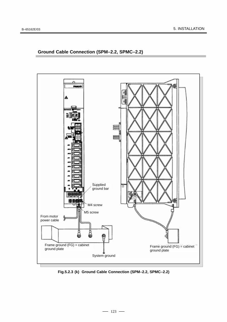
B–65162E/03 5. INSTALLATION
123
Ground Cable Connection (SPM–2.2, SPMC–2.2)
ÃÃÃÃÃÃÃÃ
Supplied ground bar
ÃÃÃÃM4 screw
ÃÃÃÃM5 screw
ÃÃÃÃÃÃÃÃÃÃÃÃ
System ground
ÃÃÃÃÃÃÃÃÃÃÃÃÃÃÃÃÃÃÃÃÃÃÃÃÃÃÃ
Frame ground (FG) = cabinetground plate ÃÃÃÃÃÃÃÃÃ
ÃÃÃÃÃÃÃÃÃ
Frame ground (FG) = cabinetground plate
ÃÃÃÃÃÃÃÃÃÃ
From motorpower cable
Fig.5.2.3 (k) Ground Cable Connection (SPM–2.2, SPMC–2.2)
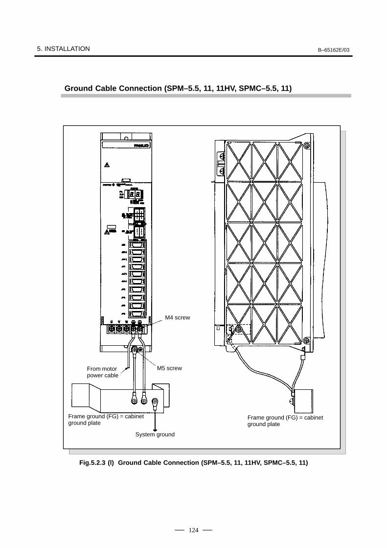
5. INSTALLATION B–65162E/03
124
Ground Cable Connection (SPM–5.5, 11, 11HV, SPMC–5.5, 11)
ÃÃÃÃÃÃÃÃ
From motorpower cable
ÃÃÃM4 screw
ÃÃÃÃM5 screw
ÃÃÃÃÃÃÃÃÃÃ
System ground
ÃÃÃÃÃÃÃÃÃÃÃÃÃÃÃÃÃÃÃÃ
Frame ground (FG) = cabinetground plate
ÃÃÃÃÃÃÃÃÃÃÃÃÃÃÃÃÃÃÃÃÃÃÃÃÃÃÃ
Frame ground (FG) = cabinetground plate
Fig.5.2.3 (l) Ground Cable Connection (SPM–5.5, 11, 11HV, SPMC–5.5, 11)
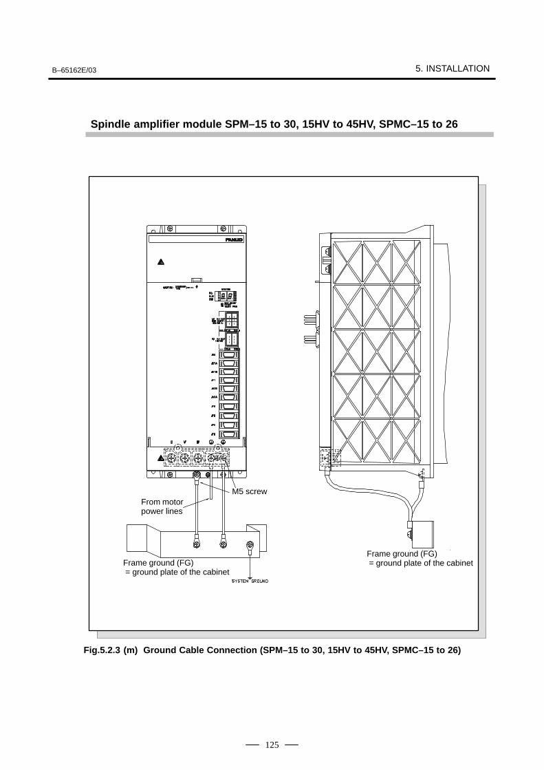
B–65162E/03 5. INSTALLATION
125
Spindle amplifier module SPM–15 to 30, 15HV to 45HV, SPMC–15 to 26
From motorpower lines
ÃÃÃM5 screw
ÃÃÃÃÃÃÃÃÃÃÃÃÃÃÃÃÃÃ
Frame ground (FG) = ground plate of the cabinet
ÃÃÃÃÃÃÃÃÃÃÃÃÃÃÃÃÃÃ
Frame ground (FG) = ground plate of the cabinet
Fig.5.2.3 (m) Ground Cable Connection (SPM–15 to 30, 15HV to 45HV, SPMC–15 to 26)
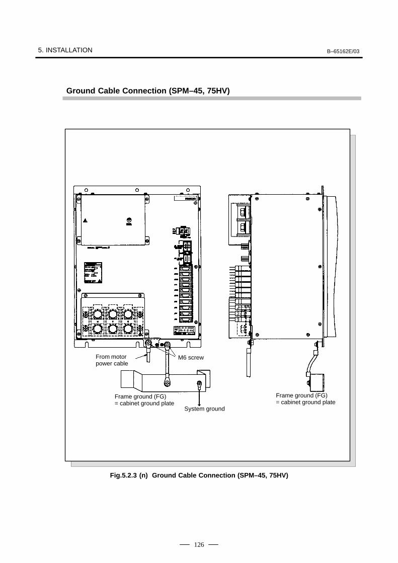
5. INSTALLATION B–65162E/03
126
Ground Cable Connection (SPM–45, 75HV)
ÃÃÃÃÃÃÃÃÃÃÃÃÃÃÃ
From motorpower cable ÃÃÃÃ
M6 screw
ÃÃÃÃÃÃÃÃÃÃÃÃÃÃÃÃ
Frame ground (FG) = cabinet ground plate
ÃÃÃÃÃÃÃÃÃÃÃÃÃÃÃÃ
Frame ground (FG) = cabinet ground plateÃÃÃÃÃÃ
ÃÃÃÃÃÃSystem ground
Fig.5.2.3 (n) Ground Cable Connection (SPM–45, 75HV)
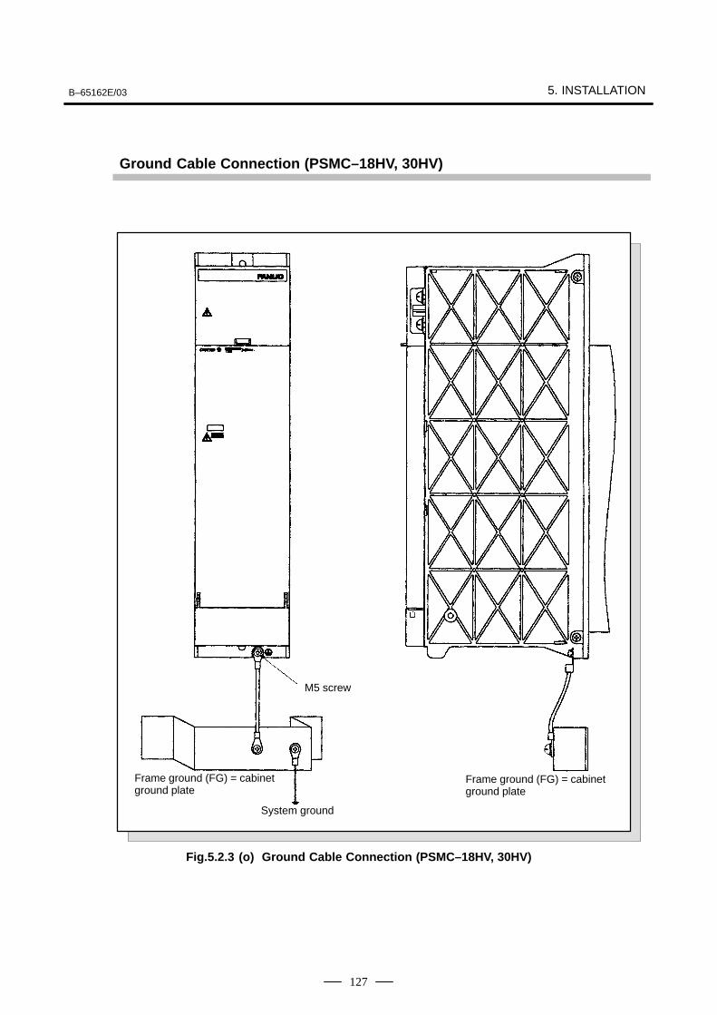
B–65162E/03 5. INSTALLATION
127
Ground Cable Connection (PSMC–18HV, 30HV)
ÃÃÃÃÃÃÃÃÃÃÃÃÃÃÃÃÃÃÃÃ
Frame ground (FG) = cabinetground plate
ÃÃÃÃÃÃÃÃÃÃÃÃ
System ground
ÃÃÃM5 screw
ÃÃÃÃÃÃÃÃÃÃÃÃÃÃÃÃÃÃÃÃ
Frame ground (FG) = cabinetground plate
Fig.5.2.3 (o) Ground Cable Connection (PSMC–18HV, 30HV)
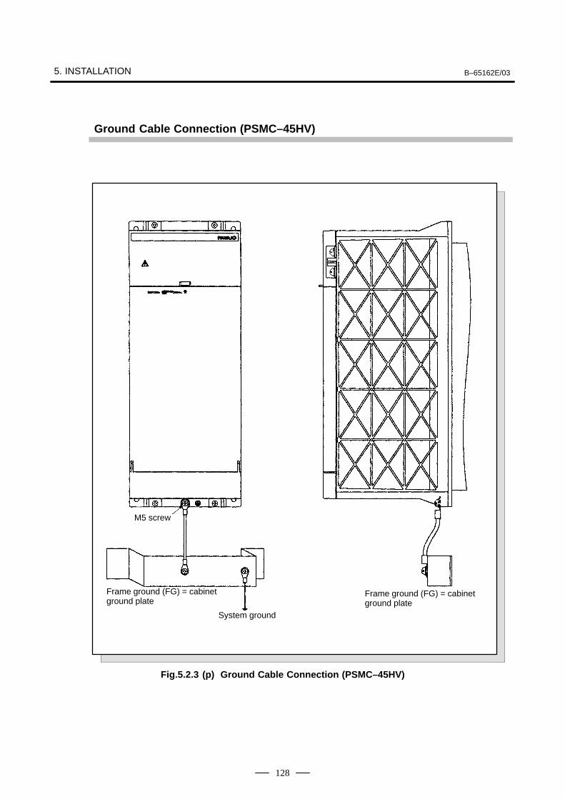
5. INSTALLATION B–65162E/03
128
Ground Cable Connection (PSMC–45HV)
ÃÃÃÃÃÃÃÃÃÃÃÃÃÃÃÃÃÃFrame ground (FG) = cabinetground plate
ÃÃÃÃÃSystem ground
ÃÃÃÃÃÃÃÃ
M5 screw
ÃÃÃÃÃÃÃÃÃÃÃÃÃÃÃÃÃÃÃÃÃÃÃÃÃÃÃÃÃÃ
Frame ground (FG) = cabinetground plate
Fig.5.2.3 (p) Ground Cable Connection (PSMC–45HV)
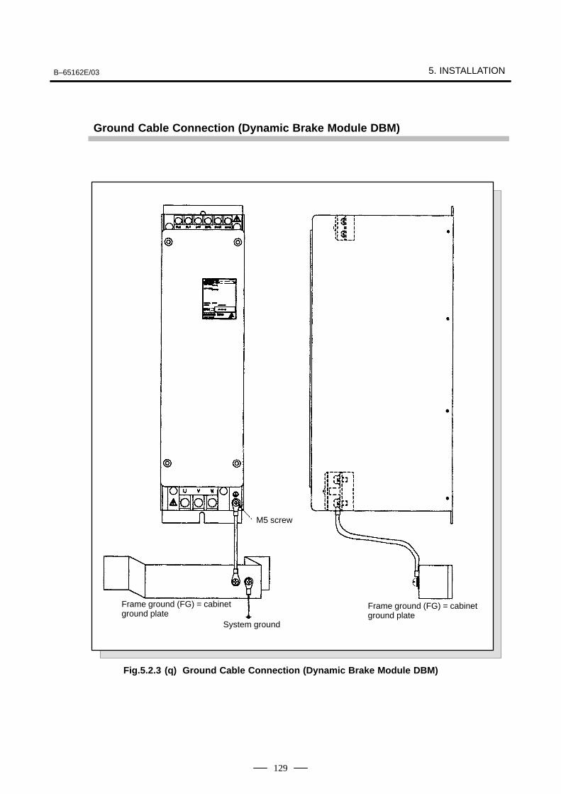
B–65162E/03 5. INSTALLATION
129
Ground Cable Connection (Dynamic Brake Module DBM)
ÃÃÃÃÃÃÃÃÃÃÃÃÃÃÃÃÃÃÃÃÃÃÃÃÃÃÃ
Frame ground (FG) = cabinetground plate
ÃÃÃÃÃÃSystem ground
ÃÃÃÃM5 screw
ÃÃÃÃÃÃÃÃÃÃÃÃÃÃÃÃÃÃÃÃÃÃÃÃÃÃÃÃÃÃ
Frame ground (FG) = cabinetground plate
Fig.5.2.3 (q) Ground Cable Connection (Dynamic Brake Module DBM)
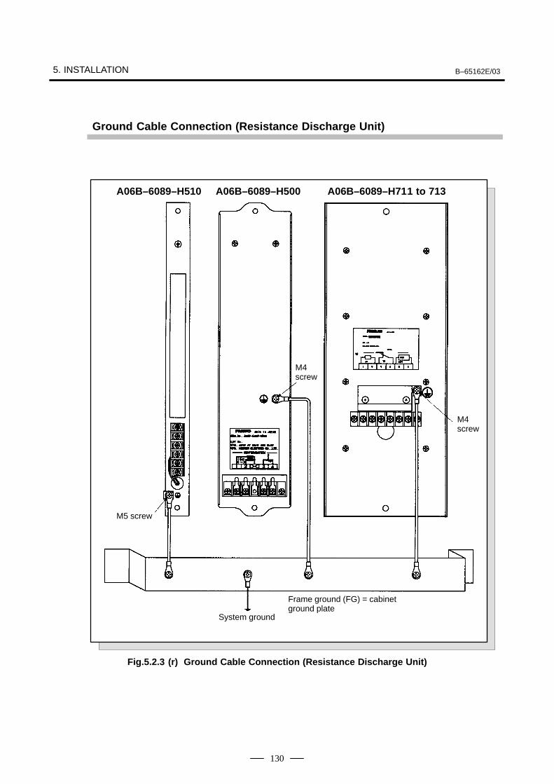
5. INSTALLATION B–65162E/03
130
Ground Cable Connection (Resistance Discharge Unit)
ÃÃÃÃÃÃSystem ground
ÃÃÃÃM5 screw
ÃÃÃÃÃÃÃÃÃÃÃÃÃÃÃÃÃÃÃÃ
Frame ground (FG) = cabinetground plate
ÃÃÃÃÃÃ
M4 screw
ÃÃÃÃÃÃ
M4 screw
A06B–6089–H510 A06B–6089–H500 A06B–6089–H711 to 713
Fig.5.2.3 (r) Ground Cable Connection (Resistance Discharge Unit)
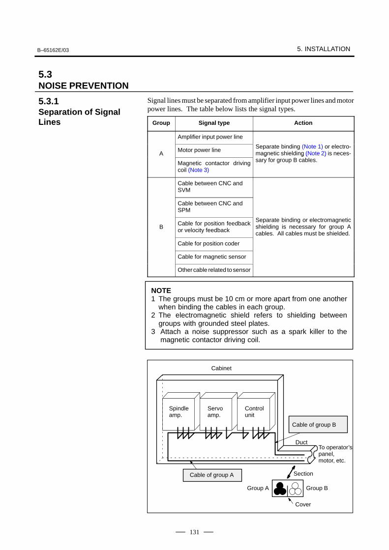
B–65162E/03 5. INSTALLATION
131
Signal lines must be separated from amplifier input power lines and motorpower lines. The table below lists the signal types.
Group Signal type Action
Amplifier input power line
AMotor power line
Separate binding (Note 1) or electro-magnetic shielding (Note 2) is neces-A
Magnetic contactor drivingcoil (Note 3)
g g ( )sary for group B cables.
Cable between CNC andSVM
Cable between CNC andSPM
BCable for position feedbackor velocity feedback
Separate binding or electromagneticshielding is necessary for group Acables. All cables must be shielded.
Cable for position coder
Cable for magnetic sensor
Other cable related to sensor
NOTE1 The groups must be 10 cm or more apart from one another
when binding the cables in each group.2 The electromagnetic shield refers to shielding between
groups with grounded steel plates.3 Attach a noise suppressor such as a spark killer to the
magnetic contactor driving coil.
Cable of group B
Cable of group A
Cabinet
Spindle amp.
Servo amp.
Control unit
DuctTo operator’s panel, motor, etc.
Section
Group A Group B
Cover
5.3NOISE PREVENTION
5.3.1Separation of SignalLines
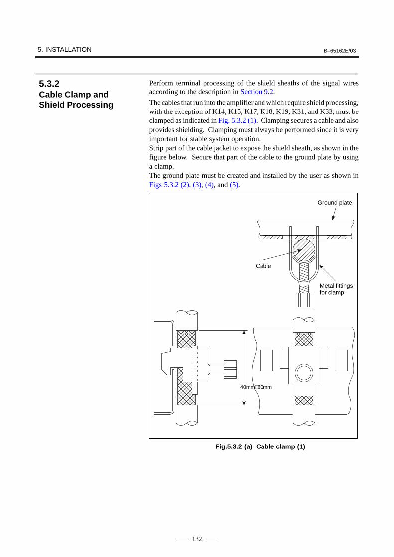
5. INSTALLATION B–65162E/03
132
Perform terminal processing of the shield sheaths of the signal wiresaccording to the description in Section 9.2.
The cables that run into the amplifier and which require shield processing,with the exception of K14, K15, K17, K18, K19, K31, and K33, must beclamped as indicated in Fig. 5.3.2 (1). Clamping secures a cable and alsoprovides shielding. Clamping must always be performed since it is veryimportant for stable system operation.Strip part of the cable jacket to expose the shield sheath, as shown in thefigure below. Secure that part of the cable to the ground plate by usinga clamp.The ground plate must be created and installed by the user as shown inFigs 5.3.2 (2), (3), (4), and (5).
Cable
Metal fittings for clamp
Ground plate
40mm∼80mm
Fig.5.3.2 (a) Cable clamp (1)
5.3.2Cable Clamp andShield Processing
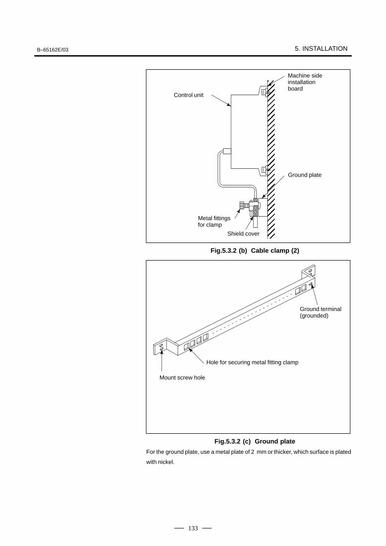
B–65162E/03 5. INSTALLATION
133
""""""""""""""""""""""""""""""""""
Control unit
Ground plate
Metal fittings for clamp
Shield cover
Machine sideinstallationboard
Fig.5.3.2 (b) Cable clamp (2)
Mount screw hole
Hole for securing metal fitting clamp
Ground terminal(grounded)
Fig.5.3.2 (c) Ground plate
For the ground plate, use a metal plate of 2 mm or thicker, which surface is plated
with nickel.
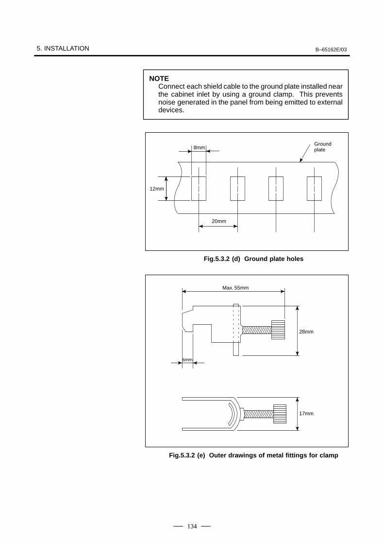
5. INSTALLATION B–65162E/03
134
NOTEConnect each shield cable to the ground plate installed nearthe cabinet inlet by using a ground clamp. This preventsnoise generated in the panel from being emitted to externaldevices.
12mm
20mm
8mmGroundplate
Fig.5.3.2 (d) Ground plate holes
17mm
28mm
6mm
Max. 55mm
Fig.5.3.2 (e) Outer drawings of metal fittings for clamp
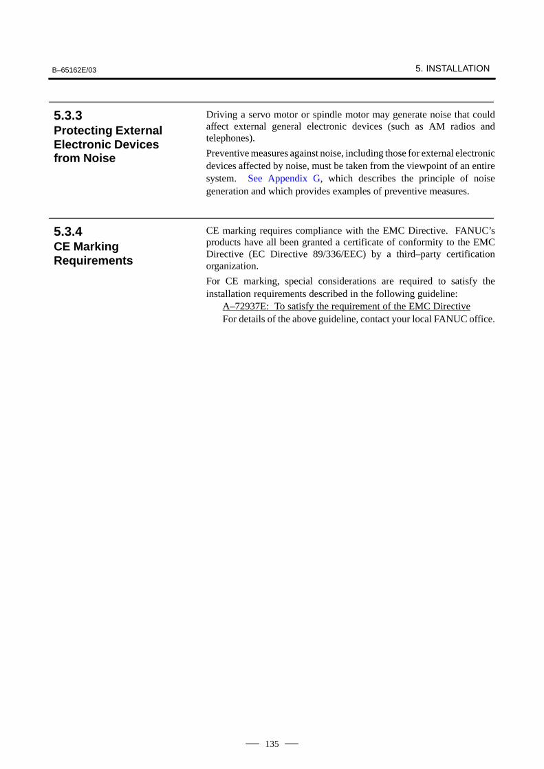
B–65162E/03 5. INSTALLATION
135
Driving a servo motor or spindle motor may generate noise that couldaffect external general electronic devices (such as AM radios andtelephones).
Preventive measures against noise, including those for external electronicdevices affected by noise, must be taken from the viewpoint of an entiresystem. See Appendix G, which describes the principle of noisegeneration and which provides examples of preventive measures.
CE marking requires compliance with the EMC Directive. FANUC’sproducts have all been granted a certificate of conformity to the EMCDirective (EC Directive 89/336/EEC) by a third–party certificationorganization.
For CE marking, special considerations are required to satisfy theinstallation requirements described in the following guideline:
A–72937E: To satisfy the requirement of the EMC DirectiveFor details of the above guideline, contact your local FANUC office.
5.3.3Protecting ExternalElectronic Devicesfrom Noise
5.3.4CE MarkingRequirements
5. INSTALLATION B–65162E/03
136
To satisfy the EMC Directive, the installation of a noise filter is requiredin the input section of the power magnetics cabinet.
The rated current of the noise filter being used is determined accordingto the type of the CNC that is connected, the type and number of motors,and the power consumption of the other peripheral devices. Using theexpression given below, calculate the noise filter load current, and selecta noise filter so that the load current does not exceed the rated current ofthe filter. Recommended noise filters are given in (12) of Section 2.2.3.
Obtaining the load current of a noise filter
The load current of a noise filter is the sum of the CNC input current, PSMinput current, and current consumption under the other loads.
Load current(Arms)
CNC inputcurrent(Arms)
PSM inputcurrent(Arms)
Current con-sumption underother loads(Arms)
= + Σ +
(Note 1) (Note 2)
NOTE1 The CNC input current is determined by the number of
PSUs (power supply units). Calculate the CNC input currentfrom the following expression:CNC input current (Arms) = 5 (Arms) x number of PSUsNormally, a CNC has one PSU. The FS15 multiaxis controlsystem has two PSUs.
2 For details of how to obtain the PSM input current, seeSections 4.1.1 or 4.2.1.
3 Attach a noise suppressor such as a spark killer to themagnetic contactor driving coil. When more than one PSMis connected, sum the input currents of the PSMs.
5.3.5Selecting a Noise Filter
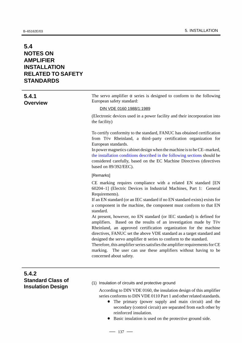
B–65162E/03 5. INSTALLATION
137
The servo amplifier α series is designed to conform to the followingEuropean safety standard:
DIN VDE 0160 1988/1:1989
(Electronic devices used in a power facility and their incorporation intothe facility)
To certify conformity to the standard, FANUC has obtained certificationfrom Tv Rheinland, a third–party certification organization forEuropean standards.In power magnetics cabinet design when the machine is to be CE–marked,the installation conditions described in the following sections should beconsidered carefully, based on the EC Machine Directives (directivesbased on 89/392/EEC).
[Remarks]
CE marking requires compliance with a related EN standard [EN60204–1] (Electric Devices in Industrial Machines, Part 1: GeneralRequirements).If an EN standard (or an IEC standard if no EN standard exists) exists fora component in the machine, the component must conform to that ENstandard.At present, however, no EN standard (or IEC standard) is defined foramplifiers. Based on the results of an investigation made by TvRheinland, an approved certification organization for the machinedirectives, FANUC set the above VDE standard as a target standard anddesigned the servo amplifier α series to conform to the standard.Therefore, this amplifier series satisfies the amplifier requirements for CEmarking. The user can use these amplifiers without having to beconcerned about safety.
(1) Insulation of circuits and protective ground
According to DIN VDE 0160, the insulation design of this amplifierseries conforms to DIN VDE 0110 Part 1 and other related standards.
The primary (power supply and main circuit) and thesecondary (control circuit) are separated from each other byreinforced insulation.
Basic insulation is used on the protective ground side.
5.4NOTES ON AMPLIFIERINSTALLATIONRELATED TO SAFETYSTANDARDS
5.4.1Overview
5.4.2Standard Class ofInsulation Design
5. INSTALLATION B–65162E/03
138
Basic insulation is also used between the power supply main circuitand aluminum flange (integrated with a heatsink). Connect theprotective ground wire to the ground terminal of the lower aluminumflange as described in Section 5.2.3.
(2) Installation category (overvoltage category)
DIN VDE 0110 [Insulation coordination of electric apparatuses]classifies power supply facilities by the impulse voltage (relative toground) in the power supply to which the amplifier is connected.This amplifier series is designed as a device of installation category(overvoltage category) II.The layout of this amplifier series has been designed on theassumption that the rated impulse withstand voltage (impulse voltagerelative to ground) in the power supply to which the amplifier isconnected is 2.5 kV or lower.If an impulse greater than 2.5 kV, relative to ground, appears in thepower supply, it must be suppressed.Generally, this requirement is considered to be satisfied if aninsulated transformer is used in the power supply input section of amachine.If an insulated transformer is not used, install a surge protector(lightning surge absorber) between the facility and ground to suppressany impulse higher than 2.5 kV, relative to ground.
(3) Contamination class of the installation environment and power
magnetics cabinet protection level
EN 60204–1 (13. Control devices/13.3 Protection level) requiresthat, when a machine is installed in an environment equivalent to thegeneral plant level, the protection level against dust, coolant, chips,and so forth be IP54 or higher.For a power magnetics cabinet that satisfies this requirement, thecontamination class within the cabinet is considered to be class 2.The insulation of this amplifier series has been designed on theassumption that the amplifier is installed in an environment ofcontamination class 2.When using the amplifier in a general machine installationenvironment, install the amplifier in a power magnetics cabinet thatsatisfies the requirements of protection level IP54.The IP level, however, depends on the environment (atmosphere) inwhich a machine is installed. Select the protection level of the powermagnetics cabinet according to the environment.For an external heatsink cooling type amplifier with a heatsink finprotruding from the rear of the mounting flange, the fin section shouldbe in a cooling area (duct) of about IP22 to 33, and specialconsiderations should be taken not to protect the fin from directcoolant splashes or chips.
B–65162E/03 5. INSTALLATION
139
(1) Protection against direct contact to a charged part
The protection level against electric shock after the installation of thisamplifier series is equivalent to IP1X (hand protection). Thus, no livepart can be touched unconsciously or carelessly.This amplifier series must always be installed in a power magneticscabinet. According to Item 6.2.1 of EN 60204–1 ”Electric ShockProtection by Using a Cabinet,” lock the power magnetics cabinet sothat, while the amplifier is on, the cabinet cannot be opened bypersons except special maintenance personnel or a person qualifiedfor maintenance who has been trained in protective measures againstelectric shock.When a machine operator needs to open the power magnetics cabinetto perform a certain operation, the operator must have receivedsufficient safety education, or a protection cover must be installed toprevent the operator from touching the amplifier.
(2) Checking discharge of an electrolytic capacitor
This amplifier series contains a large–capacitance electrolyticcapacitor for the power supply smoothing circuit. Even after thepower supply input circuit is turned off, this capacitor remainscharged for a while.When it proves necessary to touch the amplifier for maintenance andso forth, do not start maintenance work immediately; wait for thedischarge time indicated on the face plate of the amplifier.Alternatively, measure the residual voltage at the DC link section byusing a volt–ohm meter and check that the LED (red) for indicatingthe charge state is off to ensure safety.Standards define voltages exceeding 60 VDC as hazardous voltages.
(3) Leakage current flowing to the protective ground wire
Motors are controlled by applying a voltage to the armature with themean amplitude and frequency of the voltage changed by pulse widthmodulation. For this pulse width modulation, a chopper voltage isapplied to the power line of the motor to provide a carrier frequencyof several kilohertz.Ground drift capacitance mainly between the motor armaturewinding and case and between the power line of the motor powercable and protective ground wire causes a leakage current to flow intothe protective ground wire of the motor power cable and the machineground. Part of the leakage current also flows into the protectiveground wire of the machine.The resultant leakage current is about 1 to 2 mA per motor shaft at thecommercial power supply frequency (50/60 Hz). With themeasurement circuit defined by EN 60950, the leakage current isallowed to be much higher than 3.5 mA; this is because thehigh–frequency component sensitivity cannot be fully reduced.
5.4.3Protection AgainstElectric Shock
5. INSTALLATION B–65162E/03
140
Unless a machine is grounded, touching the machine may causeelectric shock. Take one of the following protective measures againstelectric shock:
(a) Use a protective ground wire with a copper wire cross–sectionalarea of no less than 10 mm2.
(b) Install a ground fault interrupter so that the power supply can bedisconnected immediately if a ground fault occurs.
(c) Add a protective grounding terminal to the cabinet to make adouble ground wire connection.
When using a ground fault interrupter, select an electromagneticground fault interrupter with a low high–frequency componentsensitivity, or an electronic ground fault interrupter that can be usedwith inverters.
Amplifiers have multiple protective grounding terminals (marked asdefined by 417–IEC–5019). These terminals are used to prevent electricshock in case of dielectric breakdown, and are also used for functionalgrounding to prevent noise.
All protective ground terminals must be connected to the protectiveground (PE) connection terminals in the power magnetics cabinet.For how to connect the protective ground wires and the cross–sectionalareas of these wires, see Section 5.2.3.Note that cables from cable terminals cannot be secured together withprotective ground terminals.
The amplifier uses IGBT (transistors) as an internal means of turning offthe power system; it does not use an electromechanical means.
Therefore, when an emergency stop circuit is configured, a line contactorenabling electromechanical disconnection must be installed on the powerinput line for feeding power to the power supply module so that a voltageis applied to the control coil of the contactor via the contactor controloutput of the power supply module.Some amplifier failures may prevent the output relay of the power supplymodule from being turned off even when the amplifier emergency stopcommand input (*ESP) is driven low, thus disabling disconnection by theline contactor.The emergency stop circuit must disconnect power without fail. It musthave a redundant circuit configuration having a route through which theline contactor is disconnected directly by the command generated by theemergency stop operation switch, independent of the disconnectionfunction provided by the amplifier.If the power line is disconnected during spindle rotation when a spindleamplifier module is used, the spindle may not be able to be stoppedimmediately by the power regeneration function, and may keep rotatingby the force of inertia. Therefore, on the redundant circuit side, a delayfunction must be provided which is based on an off–delay timerconsidering a normal stop time.
5.4.4Protective Installation
5.4.5Notes on theEmergency StopCircuit Configuration
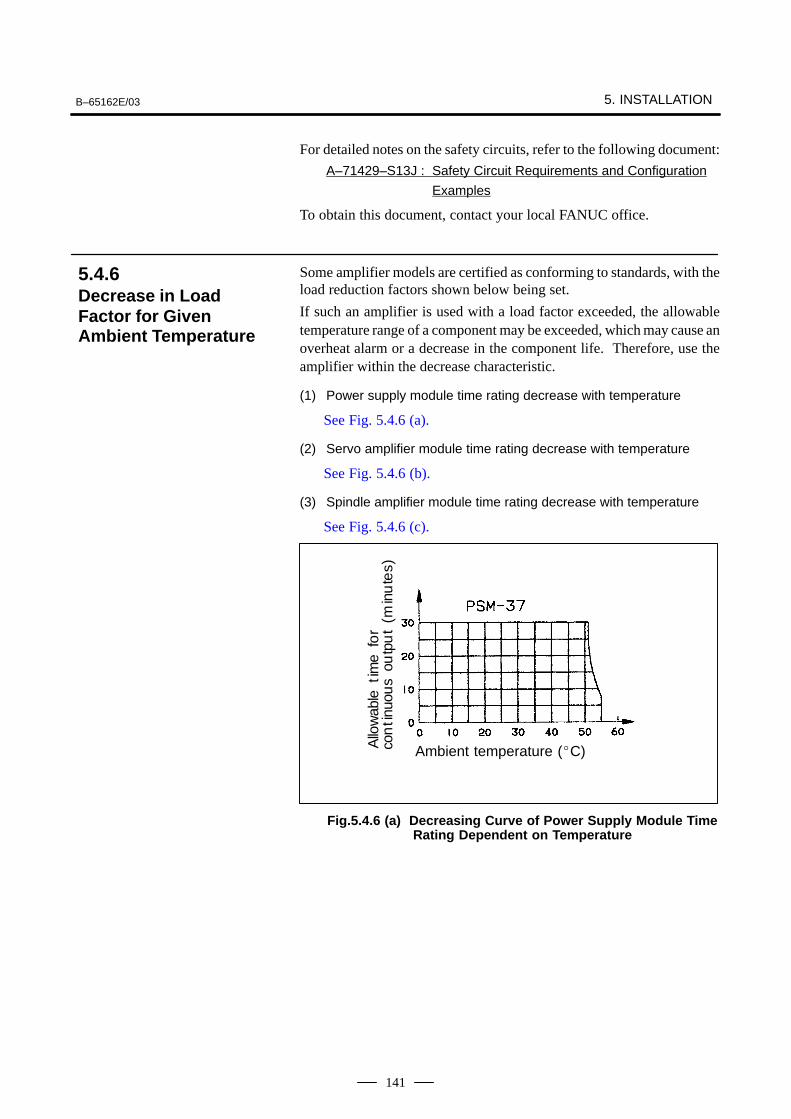
B–65162E/03 5. INSTALLATION
141
For detailed notes on the safety circuits, refer to the following document:
A–71429–S13J : Safety Circuit Requirements and Configuration
Examples
To obtain this document, contact your local FANUC office.
Some amplifier models are certified as conforming to standards, with theload reduction factors shown below being set.
If such an amplifier is used with a load factor exceeded, the allowabletemperature range of a component may be exceeded, which may cause anoverheat alarm or a decrease in the component life. Therefore, use theamplifier within the decrease characteristic.
(1) Power supply module time rating decrease with temperature
See Fig. 5.4.6 (a).
(2) Servo amplifier module time rating decrease with temperature
See Fig. 5.4.6 (b).
(3) Spindle amplifier module time rating decrease with temperature
See Fig. 5.4.6 (c).
ÃÃÃÃÃÃÃÃÃÃÃÃÃÃÃÃÃÃÃÃÃÃAmbient temperature (C)
ÃÃÃÃÃÃÃÃÃÃÃÃÃÃÃÃÃÃ
Allo
wab
leti
me
for
con
tinu
ous
outp
ut
(min
ute
s)
Fig.5.4.6 (a) Decreasing Curve of Power Supply Module TimeRating Dependent on Temperature
5.4.6Decrease in LoadFactor for GivenAmbient Temperature
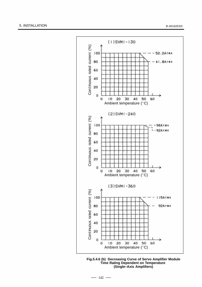
5. INSTALLATION B–65162E/03
142
ÃÃÃÃÃÃÃÃÃÃAmbient temperature (C)
ÃÃÃÃÃÃÃÃÃÃÃÃÃÃÃÃÃÃÃÃ
Ambient temperature (C)
ÃÃÃÃÃÃÃÃÃÃAmbient temperature (C)
ÃÃÃÃÃÃÃÃÃÃÃÃÃÃÃÃÃÃ
ÃÃÃÃÃÃÃÃÃÃÃÃÃÃÃÃÃÃ
ÃÃÃÃÃÃÃÃÃÃÃÃÃÃÃÃÃÃ
Con
tinu
ous
rate
dcu
rren
t(%
)C
onti
nuou
sra
ted
curr
ent
(%)
Con
tinu
ous
rate
dcu
rren
t(%
)
Fig.5.4.6 (b) Decreasing Curve of Servo Amplifier ModuleTime Rating Dependent on Temperature
(Single–Axis Amplifiers)
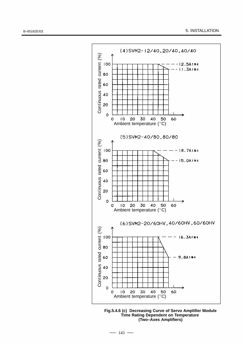
B–65162E/03 5. INSTALLATION
143
ÃÃÃÃÃÃÃÃÃÃAmbient temperature (C)
ÃÃÃÃÃÃÃÃÃÃÃÃÃÃÃÃÃÃÃÃ
Ambient temperature (C)
ÃÃÃÃÃÃÃÃÃÃAmbient temperature (C)
ÃÃÃÃÃÃÃÃÃÃÃÃÃÃÃÃÃÃÃÃÃÃÃÃÃÃÃ
ÃÃÃÃÃÃÃÃÃÃÃÃÃÃÃÃÃÃÃÃÃÃÃÃÃÃÃ
ÃÃÃÃÃÃÃÃÃÃÃÃÃÃÃÃÃÃ
Con
tinu
ous
rate
dcu
rren
t(%
)C
onti
nuou
sra
ted
curr
ent
(%)
Con
tinu
ous
rate
dcu
rren
t(%
)
Fig.5.4.6 (c) Decreasing Curve of Servo Amplifier ModuleTime Rating Dependent on Temperature
(Two–Axes Amplifiers)
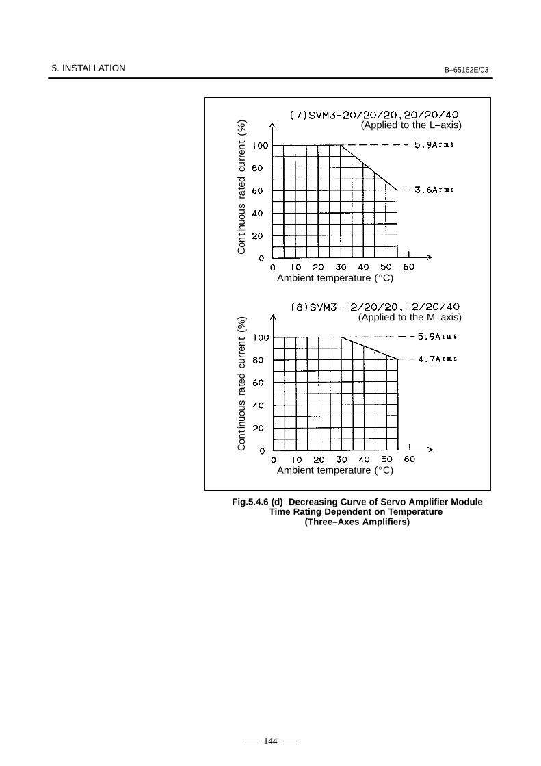
5. INSTALLATION B–65162E/03
144
ÃÃÃÃÃÃÃÃÃÃAmbient temperature (C)
ÃÃÃÃÃÃÃÃÃÃÃÃÃÃÃÃÃÃÃÃ
Ambient temperature (C)
ÃÃÃÃÃÃÃÃÃÃÃÃÃÃÃÃÃÃ
ÃÃÃÃÃÃÃÃÃÃÃÃÃÃÃÃÃÃ
Con
tinu
ous
rate
dcu
rren
t(%
)C
onti
nuou
sra
ted
curr
ent
(%)
ÃÃÃÃÃÃÃÃÃÃÃÃÃÃÃÃÃÃ
(Applied to the L–axis)
ÃÃÃÃÃÃÃÃ(Applied to the M–axis)
Fig.5.4.6 (d) Decreasing Curve of Servo Amplifier ModuleTime Rating Dependent on Temperature
(Three–Axes Amplifiers)
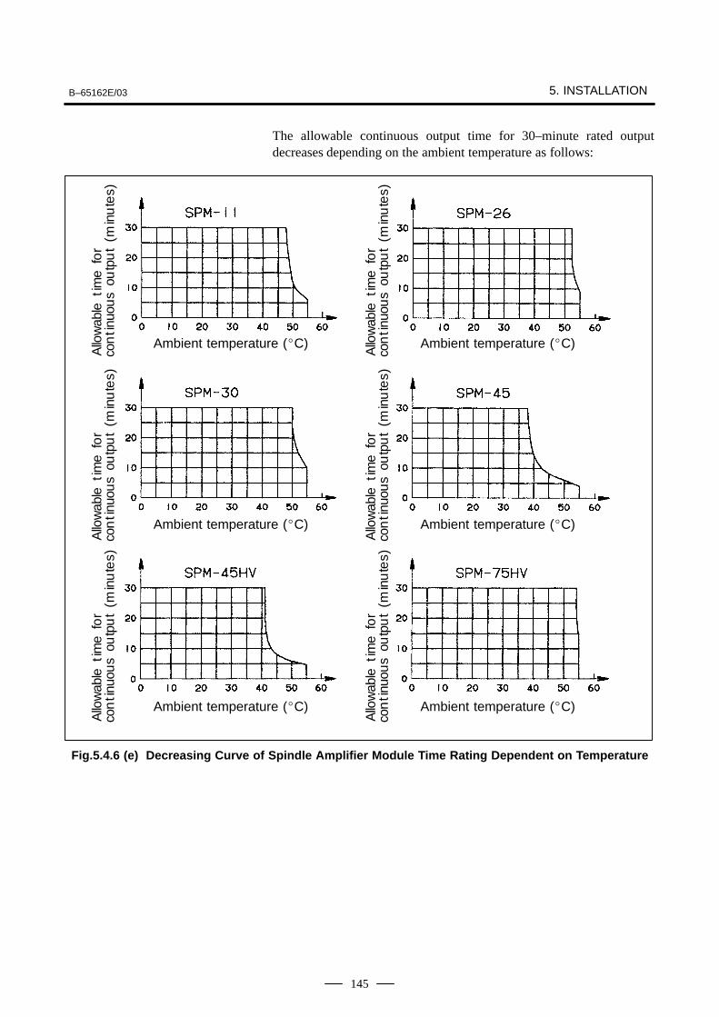
B–65162E/03 5. INSTALLATION
145
The allowable continuous output time for 30–minute rated outputdecreases depending on the ambient temperature as follows:
ÃÃÃÃÃÃÃÃÃÃÃÃÃÃÃÃÃÃÃÃÃÃAmbient temperature (C)
ÃÃÃÃÃÃÃÃÃÃÃÃÃÃÃÃÃÃÃÃÃÃ
Ambient temperature (C)
ÃÃÃÃÃÃÃÃÃÃÃAmbient temperature (C)
ÃÃÃÃÃÃÃÃÃÃÃÃÃÃÃÃÃÃÃÃAmbient temperature (C)
ÃÃÃÃÃÃÃÃÃÃÃÃÃÃÃÃÃÃÃÃAmbient temperature (C)
ÃÃÃÃÃÃÃÃÃÃAmbient temperature (C)
ÃÃÃÃÃÃÃÃÃÃÃÃÃÃÃÃÃÃ
ÃÃÃÃÃÃÃÃÃÃÃÃÃÃÃÃÃÃ
ÃÃÃÃÃÃÃÃÃÃÃÃÃÃÃÃ
ÃÃÃÃÃÃÃÃÃÃÃÃÃÃÃÃ
ÃÃÃÃÃÃÃÃÃÃÃÃÃÃÃÃÃÃÃÃÃÃÃÃÃÃÃ
ÃÃÃÃÃÃÃÃÃÃÃÃÃÃÃÃ
Allo
wab
leti
me
for
con
tinu
ous
outp
ut
(min
ute
s)A
llow
able
tim
efo
rco
nti
nuou
sou
tpu
t(m
inu
tes)
Allo
wab
leti
me
for
con
tinu
ous
outp
ut
(min
ute
s)
Allo
wab
leti
me
for
con
tinu
ous
outp
ut
(min
ute
s)A
llow
able
tim
efo
rco
nti
nuou
sou
tpu
t(m
inu
tes)
Allo
wab
leti
me
for
con
tinu
ous
outp
ut
(min
ute
s)
Fig.5.4.6 (e) Decreasing Curve of Spindle Amplifier Module Time Rating Dependent on Temperature

B–65162E/03
146
6
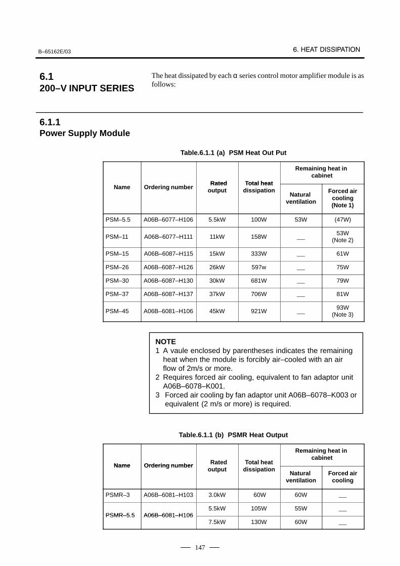
B–65162E/03
147
The heat dissipated by each α series control motor amplifier module is asfollows:
Table.6.1.1 (a) PSM Heat Out Put
Rated Total heat
Remaining heat in cabinet
Name Ordering number Rated output
Total heatdissipation
Natural ventilation
Forced aircooling(Note 1)
PSM–5.5 A06B–6077–H106 5.5kW 100W 53W (47W)
PSM–11 A06B–6077–H111 11kW 158W 53W
(Note 2)
PSM–15 A06B–6087–H115 15kW 333W 61W
PSM–26 A06B–6087–H126 26kW 597w 75W
PSM–30 A06B–6087–H130 30kW 681W 79W
PSM–37 A06B–6087–H137 37kW 706W 81W
PSM–45 A06B–6081–H106 45kW 921W 93W
(Note 3)
NOTE1 A vaule enclosed by parentheses indicates the remaining
heat when the module is forcibly air–cooled with an airflow of 2m/s or more.
2 Requires forced air cooling, equivalent to fan adaptor unitA06B–6078–K001.
3 Forced air cooling by fan adaptor unit A06B–6078–K003 orequivalent (2 m/s or more) is required.
Table.6.1.1 (b) PSMR Heat Output
Name Ordering n mber Rated Total heat
Remaining heat in cabinet
Name Ordering number Rated output
Total heatdissipation
Natural ventilation
Forced aircooling
PSMR–3 A06B–6081–H103 3.0kW 60W 60W
PSMR–5 5 A06B–6081–H1065.5kW 105W 55W
PSMR–5.5 A06B–6081–H1067.5kW 130W 60W
6.1200–V INPUT SERIES
6.1.1Power Supply Module
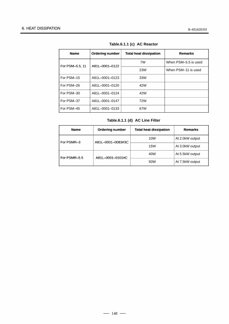
B–65162E/03
148
Table.6.1.1 (c) AC Reactor
Name Ordering n mber Total heat dissipation RemarksName Ordering number Total heat dissipation Remarks
For PSM–5 5 11 A81L–0001–01227W When PSM–5.5 is used
For PSM–5.5, 11 A81L–0001–012223W When PSM–11 is used
For PSM–15 A81L–0001–0123 33W
For PSM–26 A81L–0001–0120 42W
For PSM–30 A81L–0001–0124 42W
For PSM–37 A81L–0001–0147 72W
For PSM–45 A81L–0001–0133 67W
Table.6.1.1 (d) AC Line Filter
Name Ordering n mber Total heat dissipation RemarksName Ordering number Total heat dissipation Remarks
For PSMR–3 A81L–0001–0083#3C10W At 2.0kW output
For PSMR–3 A81L–0001–0083#3C15W At 3.0kW output
For PSMR–5 5 A81L–0001–0101#C40W At 5.5kW output
For PSMR–5.5 A81L–0001–0101#C50W At 7.5kW output
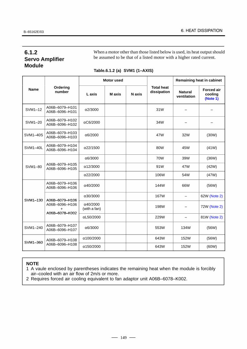
B–65162E/03
149
When a motor other than those listed below is used, its heat output shouldbe assumed to be that of a listed motor with a higher rated current.
Table.6.1.2 (a) SVM1 (1–AXIS)
Motor used Remaining heat in cabinet
Name Orderingnumber
L axis M axis N axis
Total heatdissipation Natural
ventilation
Forced aircooling(Note 1)
SVM1–12A06B–6079–H101A06B–6096–H101 α2/3000 31W – –
SVM1–20A06B–6079–H102A06B–6096–H102 αC6/2000 34W – –
SVM1–40SA06B–6079–H103A06B–6096–H103 α6/2000 47W 32W (30W)
SVM1–40LA06B–6079–H104A06B–6096–H104 α22/1500 80W 45W (41W)
α6/3000 70W 39W (36W)
SVM1–80A06B–6079–H105A06B–6096–H105 α12/3000 91W 47W (42W)
α22/2000 106W 54W (47W)
A06B–6079–H106A06B–6096–H106 α40/2000 144W 66W (56W)
SVM1–130 A06B–6079–H106α30/3000 167W – 62W (Note 2)
SVM1–130 A06B–6079–H106A06B–6096–H106
+A06B–6078–K002
α40/2000(with a fan) 198W – 72W (Note 2)
A06B–6078–K002αL50/2000 229W – 81W (Note 2)
SVM1–240A06B–6079–H107A06B–6096–H107 α6/3000 553W 134W (56W)
SVM1–360A06B–6079–H108A B H
α100/2000 643W 152W (56W)SVM1–360 A06B–6096–H108 α150/2000 643W 152W (60W)
NOTE1 A vaule enclosed by parentheses indicates the remaining heat when the module is forcibly
air–cooled with an air flow of 2m/s or more.2 Requires forced air cooling equivalent to fan adaptor unit A06B–6078–K002.
6.1.2Servo Amplifier Module
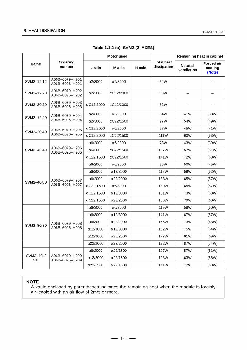
B–65162E/03
150
Table.6.1.2 (b) SVM2 (2–AXES)
Motor used Remaining heat in cabinet
Name Orderingnumber L axis M axis N axis
Total heatdissipation Natural
ventilation
Forced aircooling(Note)
SVM2–12/12A06B–6079–H201A06B–6096–H201 α2/3000 α2/3000 54W – –
SVM2–12/20A06B–6079–H202A06B–6096–H202 α2/3000 αC12/2000 68W – –
SVM2–20/20A06B–6079–H203A06B–6096–H203 αC12/2000 αC12/2000 82W – –
SVM2–12/40 A06B–6079–H204 α2/3000 α6/2000 64W 41W (38W)SVM2–12/40 A06B 6079 H204
A06B–6096–H204 α2/3000 αC22/1500 97W 54W (49W)
SVM2–20/40 A06B–6079–H205 αC12/2000 α6/2000 77W 45W (41W)SVM2–20/40 A06B 6079 H205
A06B–6096–H205 αC12/2000 αC22/1500 111W 60W (53W)
A06B 6079 H206α6/2000 α6/2000 73W 43W (39W)
SVM2–40/40 A06B–6079–H206A06B–6096–H206
α6/2000 αC22/1500 107W 57W (51W)A06B 6096 H206
αC22/1500 αC22/1500 141W 72W (63W)
α6/2000 α6/3000 96W 50W (45W)
α6/2000 α12/3000 118W 59W (52W)
SVM2–40/80 A06B–6079–H207 α6/2000 α22/2000 133W 65W (57W)SVM2–40/80 A06B 6079 H207
A06B–6096–H207 αC22/1500 α6/3000 130W 65W (57W)
αC22/1500 α12/3000 151W 73W (63W)
αC22/1500 α22/2000 166W 79W (68W)
α6/3000 α6/3000 119W 58W (50W)
α6/3000 α12/3000 141W 67W (57W)
SVM2–80/80 A06B–6079–H208 α6/3000 α22/2000 156W 73W (63W)SVM2–80/80 A06B 6079 H208
A06B–6096–H208 α12/3000 α12/3000 162W 75W (64W)
α12/3000 α22/2000 177W 81W (69W)
α22/2000 α22/2000 192W 87W (74W)
SVM2 40L/ A06B 6079 H209α6/2000 α22/1500 107W 57W (51W)
SVM2–40L/40L
A06B–6079–H209A06B–6096–H209
α12/2000 α22/1500 123W 63W (56W)40L A06B 6096 H209
α22/1500 α22/1500 141W 72W (63W)
NOTEA vaule enclosed by parentheses indicates the remaining heat when the module is forciblyair–cooled with an air flow of 2m/s or more.
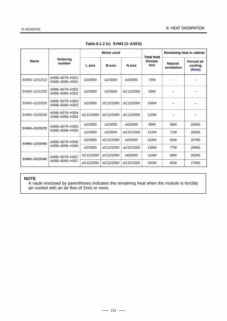
B–65162E/03
151
Table.6.1.2 (c) SVM3 (3–AXES)
Motor usedTotal heat
Remaining heat in cabinet
Name Orderingnumber
L axis M axis N axis
Total heatdissipa-
tion Natural ventilation
Forced aircooling(Note)
SVM3–12/12/12A06B–6079–H301A06B–6096–H301 α2/3000 α2/3000 α2/3000 79W – –
SVM3–12/12/20A06B–6079–H302A06B–6096–H302 α2/3000 α2/3000 αC12/2000 93W – –
SVM3–12/20/20A06B–6079–H303A06B–6096–H303 α2/3000 αC12/2000 αC12/2000 106W – –
SVM3–12/20/20A06B–6079–H304A06B–6096–H304 αC12/2000 αC12/2000 αC12/2000 120W – –
SVM3–20/20/20 A06B–6079–H305α2/3000 α2/3000 α6/2000 89W 58W (54W)
SVM3–20/20/20 A06B 6079 H305A06B–6096–H305 α2/3000 α2/3000 αC22/1500 122W 71W (65W)
SVM3–12/20/40 A06B–6079–H306α2/3000 αC12/2000 α6/2000 102W 62W (57W)
SVM3–12/20/40 A06B 6079 H306A06B–6096–H306 α2/3000 αC12/2000 αC22/1500 136W 77W (69W)
SVM3–20/20/40A06B–6079–H307A B H
αC12/2000 αC12/2000 α6/2000 116W 68W (62W)SVM3–20/20/40 A06B–6096–H307 αC12/2000 αC12/2000 αC22/1500 150W 82W (74W)
NOTEA vaule enclosed by parentheses indicates the remaining heat when the module is forciblyair–cooled with an air flow of 2m/s or more.
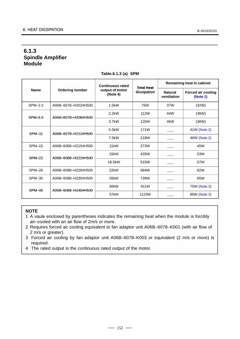
B–65162E/03
152
Table.6.1.3 (a) SPM
Continuous rated Total heatRemaining heat in cabinet
Name Ordering numberContinuous ratedoutput of motor
(Note 4)
Total heatdissipation Natural
ventilationForced air cooling
(Note 1)
SPM–2.2 A06B–6078–H202#H500 1.5kW 75W 37W (32W)
SPM–5 5 A06B–6078–H206#H5002.2kW 112W 44W (36W)
SPM–5.5 A06B–6078–H206#H5003.7kW 120W 46W (36W)
SPM–11 A06B–6078–H211#H5005.5kW 171W 41W (Note 2)
SPM–11 A06B–6078–H211#H5007.5kW 218W 46W (Note 2)
SPM–15 A06B–6088–H215#H500 11kW 273W 45W
SPM–22 A06B–6088–H222#H50015kW 435W 53W
SPM–22 A06B–6088–H222#H50018.5kW 515W 57W
SPM–26 A06B–6088–H226#H500 22kW 684W 62W
SPM–30 A06B–6088–H230#H500 26kW 739W 65W
SPM–45 A06B–6088–H245#H50030kW 911W 75W (Note 3)
SPM–45 A06B–6088–H245#H50037kW 1123W 85W (Note 3)
NOTE1 A vaule enclosed by parentheses indicates the remaining heat when the module is forcibly
air–cooled with an air flow of 2m/s or more.2 Requires forced air cooling equivalent to fan adaptor unit A06B–6078–K001 (with air flow of
2 m/s or greater).3 Forced air cooling by fan adaptor unit A06B–6078–K003 or equivalent (2 m/s or more) is
required.4 The rated output is the continuous rated output of the motor.
6.1.3Spindle AmplifierModule
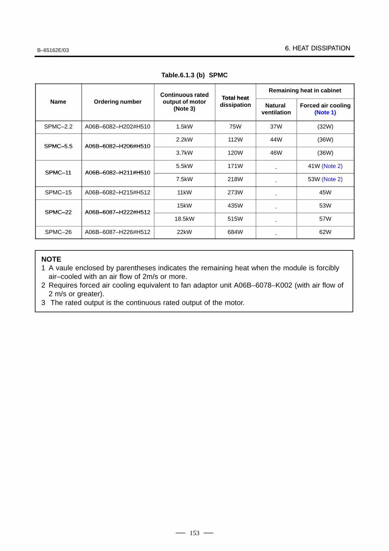
B–65162E/03
153
Table.6.1.3 (b) SPMC
Continuous rated Total heatRemaining heat in cabinet
Name Ordering numberContinuous ratedoutput of motor
(Note 3)
Total heatdissipation Natural
ventilationForced air cooling
(Note 1)
SPMC–2.2 A06B–6082–H202#H510 1.5kW 75W 37W (32W)
SPMC–5 5 A06B–6082–H206#H5102.2kW 112W 44W (36W)
SPMC–5.5 A06B–6082–H206#H5103.7kW 120W 46W (36W)
SPMC–11 A06B–6082–H211#H5105.5kW 171W 41W (Note 2)
SPMC–11 A06B–6082–H211#H5107.5kW 218W 53W (Note 2)
SPMC–15 A06B–6082–H215#H512 11kW 273W 45W
SPMC–22 A06B–6087–H222#H51215kW 435W 53W
SPMC–22 A06B–6087–H222#H51218.5kW 515W 57W
SPMC–26 A06B–6087–H226#H512 22kW 684W 62W
NOTE1 A vaule enclosed by parentheses indicates the remaining heat when the module is forcibly
air–cooled with an air flow of 2m/s or more.2 Requires forced air cooling equivalent to fan adaptor unit A06B–6078–K002 (with air flow of
2 m/s or greater).3 The rated output is the continuous rated output of the motor.
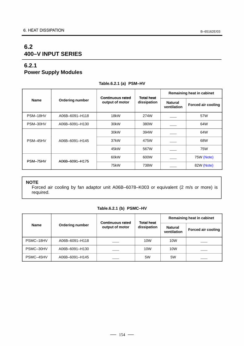
B–65162E/03
154
Table.6.2.1 (a) PSM–HV
Contin o s rated Total heatRemaining heat in cabinet
Name Ordering numberContin uous ratedoutput of motor
Total heatdissipation Natural
ventilation Forced air cooling
PSM–18HV A06B–6091–H118 18kW 274W 57W
PSM–30HV A06B–6091–H130 30kW 380W 64W
30kW 394W 64W
PSM–45HV A06B–6091–H145 37kW 475W 68W
45kW 567W 75W
PSM–75HV A06B–6091–H17560kW 600W 75W (Note)
PSM–75HV A06B–6091–H17575kW 738W 82W (Note)
NOTEForced air cooling by fan adaptor unit A06B–6078–K003 or equivalent (2 m/s or more) isrequired.
Table.6.2.1 (b) PSMC–HV
Contin o s rated Total heatRemaining heat in cabinet
Name Ordering numberContin uous ratedoutput of motor
Total heatdissipation Natural
ventilation Forced air cooling
PSMC–18HV A06B–6091–H118 10W 10W
PSMC–30HV A06B–6091–H130 10W 10W
PSMC–45HV A06B–6091–H145 5W 5W
6.2400–V INPUT SERIES
6.2.1Power Supply Modules
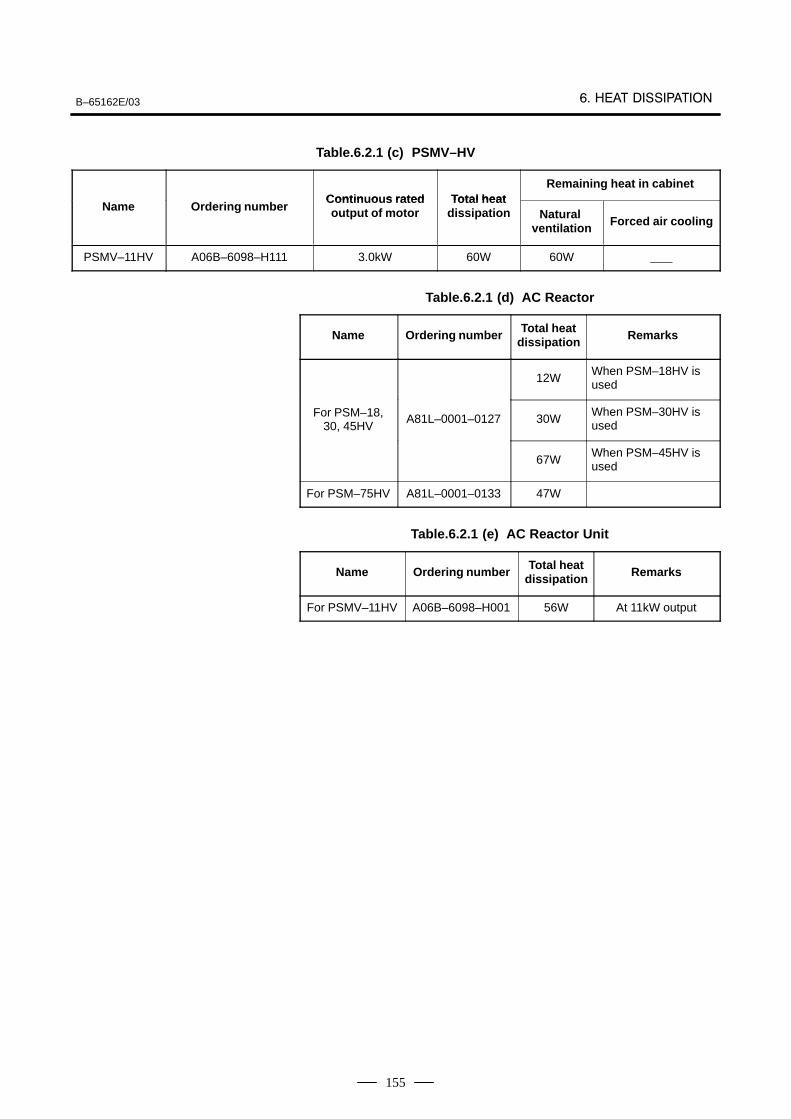
B–65162E/03
155
Table.6.2.1 (c) PSMV–HV
Contin o s rated Total heatRemaining heat in cabinet
Name Ordering numberContin uous ratedoutput of motor
Total heatdissipation Natural
ventilation Forced air cooling
PSMV–11HV A06B–6098–H111 3.0kW 60W 60W
Table.6.2.1 (d) AC Reactor
Name Ordering number Total heatdissipation Remarks
12WWhen PSM–18HV isused
For PSM–18,30, 45HV
A81L–0001–0127 30WWhen PSM–30HV isused
67WWhen PSM–45HV isused
For PSM–75HV A81L–0001–0133 47W
Table.6.2.1 (e) AC Reactor Unit
Name Ordering number Total heatdissipation Remarks
For PSMV–11HV A06B–6098–H001 56W At 11kW output
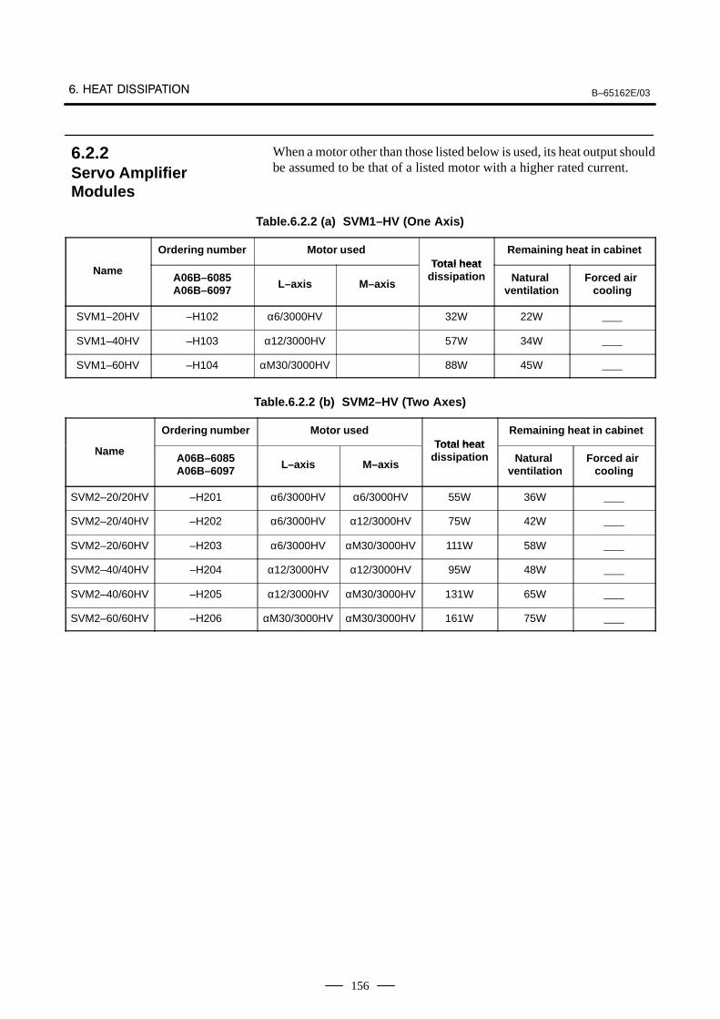
B–65162E/03
156
When a motor other than those listed below is used, its heat output shouldbe assumed to be that of a listed motor with a higher rated current.
Table.6.2.2 (a) SVM1–HV (One Axis)
Ordering number Motor usedTotal heat
Remaining heat in cabinet
NameA06B–6085A06B–6097 L–axis M–axis
Total heatdissipation Natural
ventilationForced air
cooling
SVM1–20HV –H102 α6/3000HV 32W 22W
SVM1–40HV –H103 α12/3000HV 57W 34W
SVM1–60HV –H104 αM30/3000HV 88W 45W
Table.6.2.2 (b) SVM2–HV (Two Axes)
Ordering number Motor usedTotal heat
Remaining heat in cabinet
NameA06B–6085A06B–6097 L–axis M–axis
Total heatdissipation Natural
ventilationForced air
cooling
SVM2–20/20HV –H201 α6/3000HV α6/3000HV 55W 36W
SVM2–20/40HV –H202 α6/3000HV α12/3000HV 75W 42W
SVM2–20/60HV –H203 α6/3000HV αM30/3000HV 111W 58W
SVM2–40/40HV –H204 α12/3000HV α12/3000HV 95W 48W
SVM2–40/60HV –H205 α12/3000HV αM30/3000HV 131W 65W
SVM2–60/60HV –H206 αM30/3000HV αM30/3000HV 161W 75W
6.2.2Servo AmplifierModules
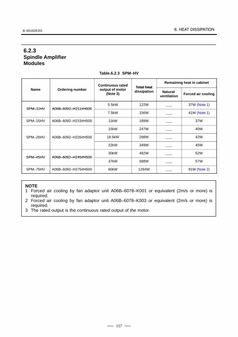
B–65162E/03
157
Table.6.2.3 SPM–HV
Continuous rated Total heatRemaining heat in cabinet
Name Ordering numberContinuous ratedoutput of motor
(Note 3)
Total heatdissipation Natural
ventilation Forced air cooling
SPM–11HV A06B–6092–H211#H5005.5kW 122W 37W (Note 1)
SPM–11HV A06B–6092–H211#H5007.5kW 156W 41W (Note 1)
SPM–15HV A06B–6092–H215#H500 11kW 189W 37W
15kW 247W 40W
SPM–26HV A06B–6092–H226#H500 18.5kW 298W 42W
22kW 349W 45W
SPM–45HV A06B–6092–H245#H50030kW 482W 52W
SPM–45HV A06B–6092–H245#H50037kW 588W 57W
SPM–75HV A06B–6092–H275#H500 60kW 1264W 91W (Note 2)
NOTE1 Forced air cooling by fan adaptor unit A06B–6078–K001 or equivalent (2m/s or more) is
required.2 Forced air cooling by fan adaptor unit A06B–6078–K003 or equivalent (2m/s or more) is
required.3 The rated output is the continuous rated output of the motor.
6.2.3Spindle AmplifierModules
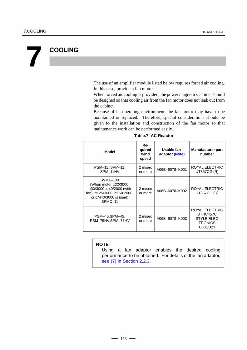
7.COOLING B–65162E/03
158
7
The use of an amplifier module listed below requires forced air cooling.In this case, provide a fan motor.When forced air cooling is provided, the power magnetics cabinet shouldbe designed so that cooling air from the fan motor does not leak out fromthe cabinet.Because of its operating environment, the fan motor may have to bemaintained or replaced. Therefore, special considerations should begiven to the installation and construction of the fan motor so thatmaintenance work can be performed easily.
Table.7 AC Reactor
Model
Re-quiredwind
speed
Usable fan adaptor (Note)
Manufacturer partnumber
PSM–11, SPM–11,SPM–11HV
2 m/secor more A06B–6078–K001
ROYAL ELECTRICUT857CG (R)
SVM1–130(When motor α22/3000,
α30/3000, α40/2000 (withfan), αL25/3000, αL50.2000,
or αM40/3000 is used)SPMC–11
2 m/secor more A06B–6078–K002
ROYAL ELECTRICUT857CG (R)
PSM–45,SPM–45,PSM–75HV,SPM–75HV
2 m/secor more A06B–6078–K003
ROYAL ELECTRICUTHC457C
STYLE ELEC-TRONICSUS12D23
NOTEUsing a fan adaptor enables the desired coolingperformance to be obtained. For details of the fan adaptor,see (7) in Section 2.2.3.

B–65162E/038. EXTERNAL DIMENSIONS AND
MAINTENANCE AREA
159
8
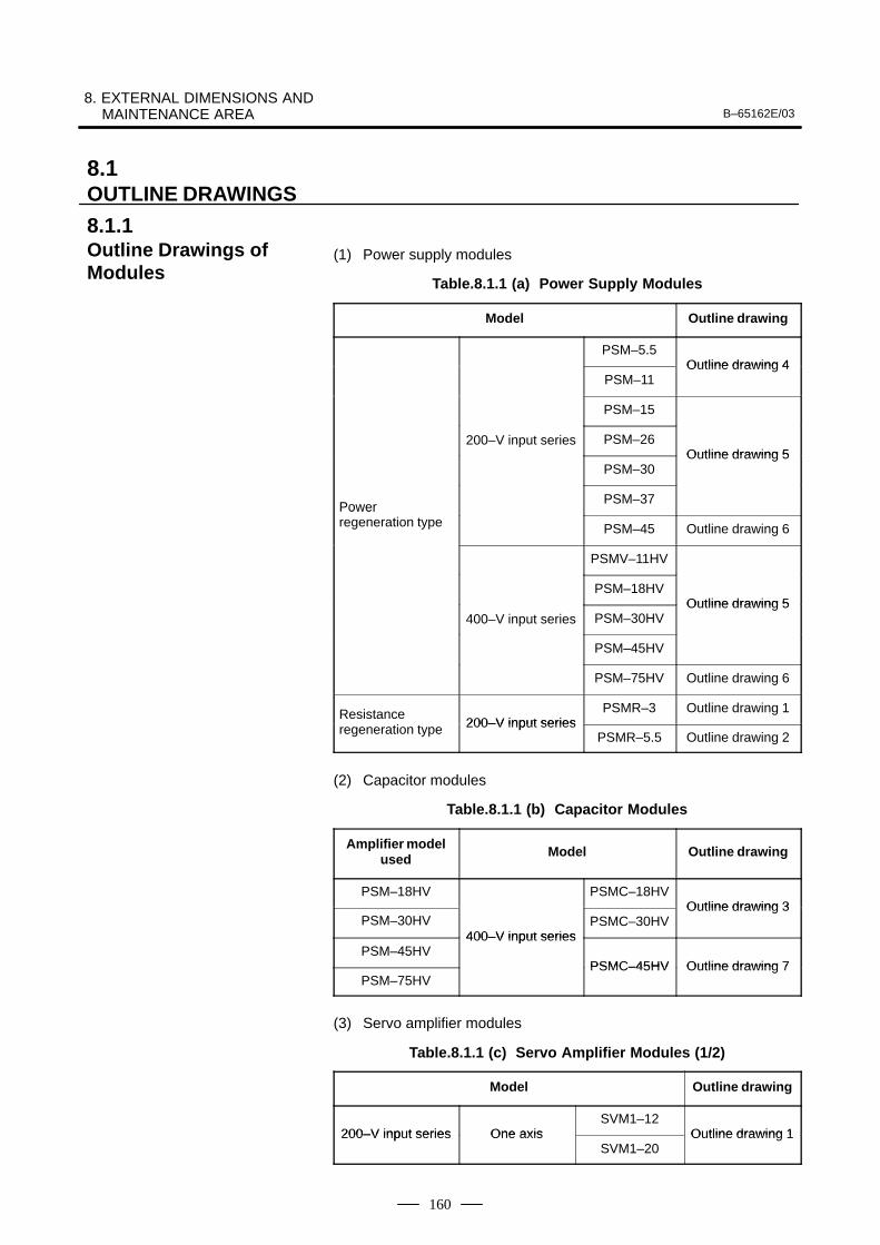
8. EXTERNAL DIMENSIONS AND MAINTENANCE AREA B–65162E/03
160
(1) Power supply modules
Table.8.1.1 (a) Power Supply Modules
Model Outline drawing
PSM–5.5Outline drawing 4
PSM–11Outline drawing 4
PSM–15
200–V input series PSM–26Outline drawing 5
PSM–30Outline drawing 5
Power PSM–37
Power regeneration type PSM–45 Outline drawing 6
PSMV–11HV
PSM–18HVOutline drawing 5
400–V input series PSM–30HVOutline drawing 5
PSM–45HV
PSM–75HV Outline drawing 6
Resistance i 200–V input series
PSMR–3 Outline drawing 1
regeneration type 200–V input seriesPSMR–5.5 Outline drawing 2
(2) Capacitor modules
Table.8.1.1 (b) Capacitor Modules
Amplifier modelused Model Outline drawing
PSM–18HV PSMC–18HVOutline drawing 3
PSM–30HV400–V input series
PSMC–30HVOutline drawing 3
PSM–45HV400–V input series
PSMC–45HV Outline drawing 7PSM–75HV
PSMC–45HV Outline drawing 7
(3) Servo amplifier modules
Table.8.1.1 (c) Servo Amplifier Modules (1/2)
Model Outline drawing
200–V input series One axisSVM1–12
Outline drawing 1200–V input series One axisSVM1–20
Outline drawing 1
8.1OUTLINE DRAWINGS
8.1.1Outline Drawings ofModules
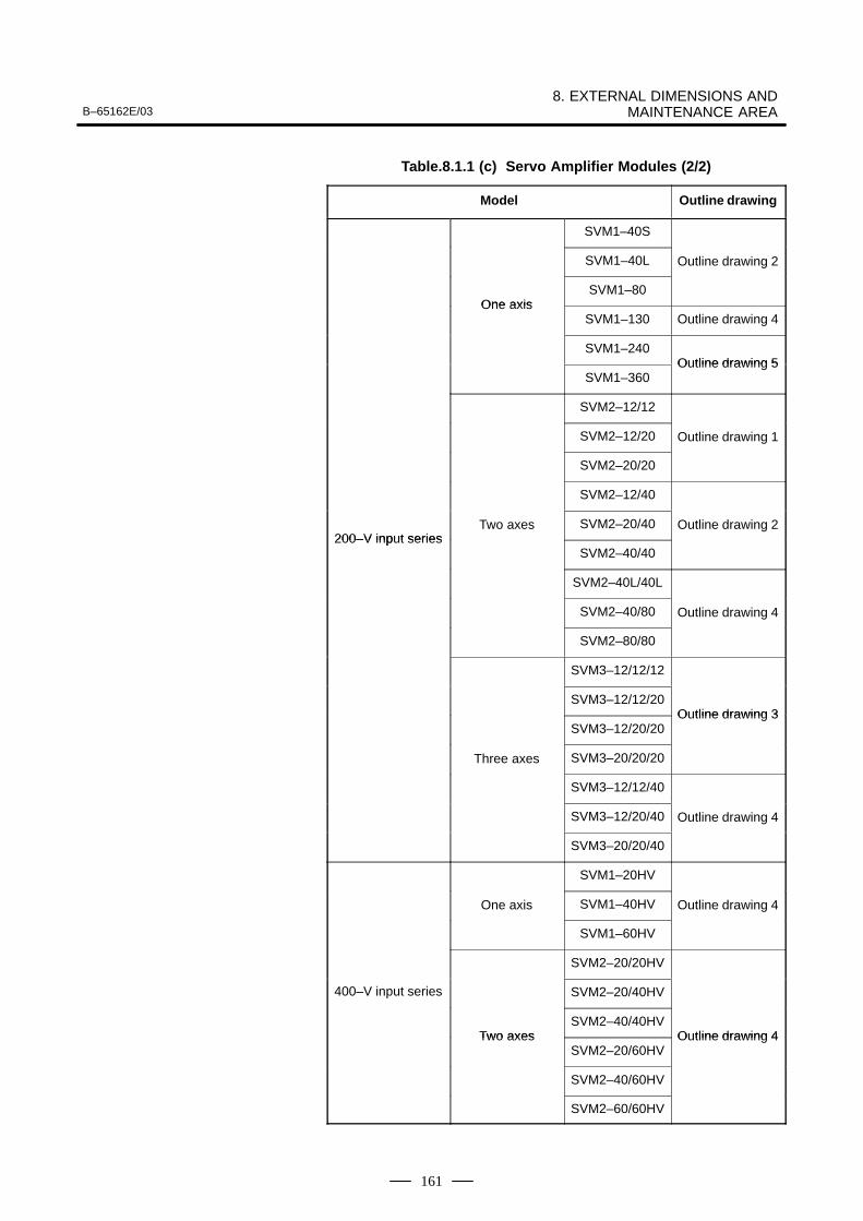
B–65162E/038. EXTERNAL DIMENSIONS AND
MAINTENANCE AREA
161
Table.8.1.1 (c) Servo Amplifier Modules (2/2)
Model Outline drawing
SVM1–40S
SVM1–40L Outline drawing 2
One axisSVM1–80
One axisSVM1–130 Outline drawing 4
SVM1–240Outline drawing 5
SVM1–360Outline drawing 5
SVM2–12/12
SVM2–12/20 Outline drawing 1
SVM2–20/20
SVM2–12/40
200–V input seriesTwo axes SVM2–20/40 Outline drawing 2
200–V input seriesSVM2–40/40
SVM2–40L/40L
SVM2–40/80 Outline drawing 4
SVM2–80/80
SVM3–12/12/12
SVM3–12/12/20Outline drawing 3
SVM3–12/20/20Outline drawing 3
Three axes SVM3–20/20/20
SVM3–12/12/40
SVM3–12/20/40 Outline drawing 4
SVM3–20/20/40
SVM1–20HV
One axis SVM1–40HV Outline drawing 4
SVM1–60HV
SVM2–20/20HV
400–V input series SVM2–20/40HV
Two axesSVM2–40/40HV
Outline drawing 4Two axesSVM2–20/60HV
Outline drawing 4
SVM2–40/60HV
SVM2–60/60HV
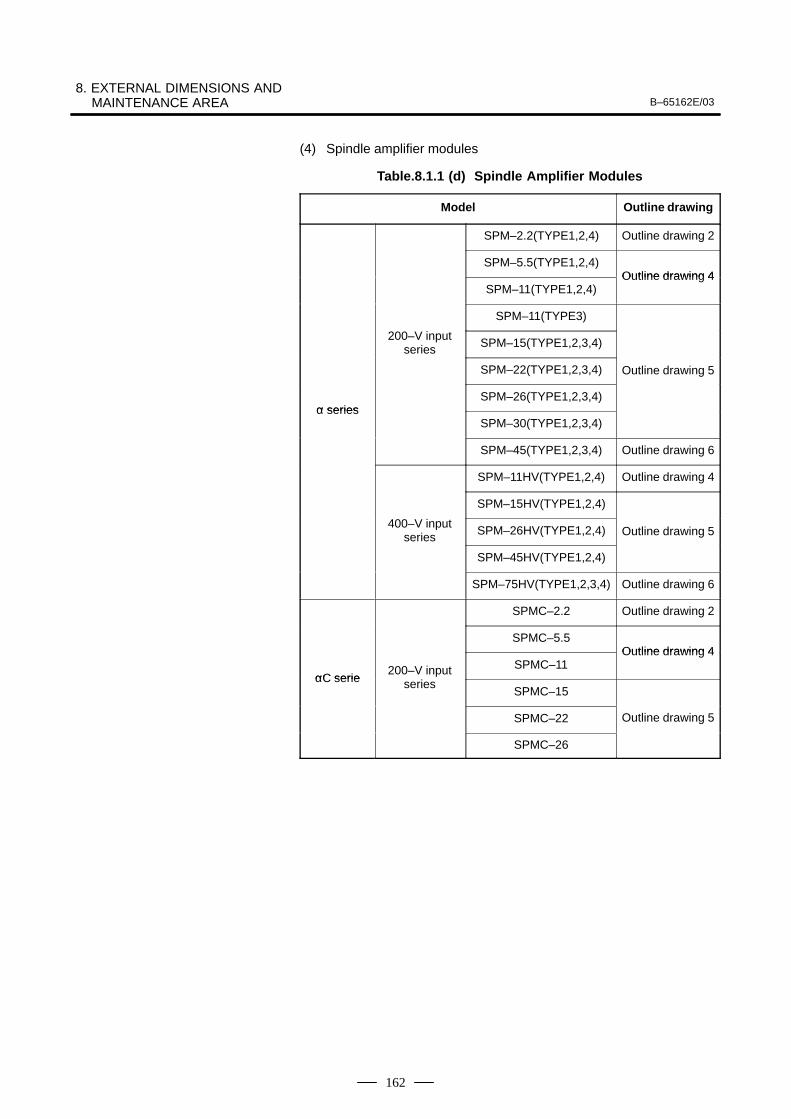
8. EXTERNAL DIMENSIONS AND MAINTENANCE AREA B–65162E/03
162
(4) Spindle amplifier modules
Table.8.1.1 (d) Spindle Amplifier Modules
Model Outline drawing
SPM–2.2(TYPE1,2,4) Outline drawing 2
SPM–5.5(TYPE1,2,4)Outline drawing 4
SPM–11(TYPE1,2,4)Outline drawing 4
SPM–11(TYPE3)
200–V inputseries SPM–15(TYPE1,2,3,4)
SPM–22(TYPE1,2,3,4) Outline drawing 5
α seriesSPM–26(TYPE1,2,3,4)
α seriesSPM–30(TYPE1,2,3,4)
SPM–45(TYPE1,2,3,4) Outline drawing 6
SPM–11HV(TYPE1,2,4) Outline drawing 4
SPM–15HV(TYPE1,2,4)
400–V inputseries SPM–26HV(TYPE1,2,4) Outline drawing 5
SPM–45HV(TYPE1,2,4)
SPM–75HV(TYPE1,2,3,4) Outline drawing 6
SPMC–2.2 Outline drawing 2
SPMC–5.5Outline drawing 4
αC serie200–V input
i
SPMC–11Outline drawing 4
αC serie seriesSPMC–15
SPMC–22 Outline drawing 5
SPMC–26
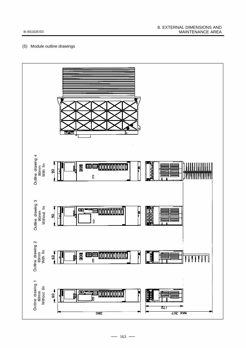
B–65162E/038. EXTERNAL DIMENSIONS AND
MAINTENANCE AREA
163
(5) Module outline drawings
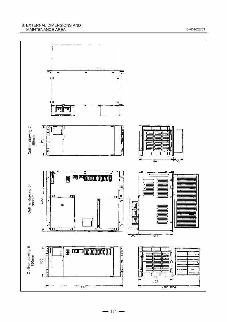
8. EXTERNAL DIMENSIONS AND MAINTENANCE AREA B–65162E/03
164
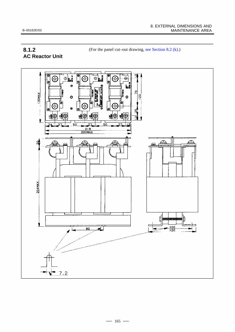
B–65162E/038. EXTERNAL DIMENSIONS AND
MAINTENANCE AREA
165
(For the panel cut–out drawing, see Section 8.2 (k).)8.1.2AC Reactor Unit
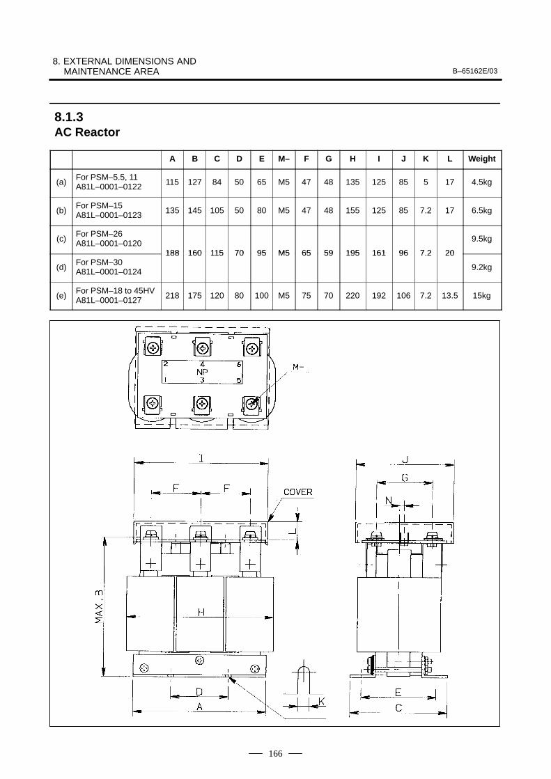
8. EXTERNAL DIMENSIONS AND MAINTENANCE AREA B–65162E/03
166
A B C D E M– F G H I J K L Weight
(a)For PSM–5.5, 11A81L–0001–0122 115 127 84 50 65 M5 47 48 135 125 85 5 17 4.5kg
(b)For PSM–15A81L–0001–0123 135 145 105 50 80 M5 47 48 155 125 85 7.2 17 6.5kg
(c)For PSM–26A81L–0001–0120
188 160 115 70 95 M5 65 59 195 161 96 7 2 20
9.5kg
(d)For PSM–30A81L–0001–0124
188 160 115 70 95 M5 65 59 195 161 96 7.2 20
9.2kg
(e)For PSM–18 to 45HVA81L–0001–0127 218 175 120 80 100 M5 75 70 220 192 106 7.2 13.5 15kg
8.1.3AC Reactor
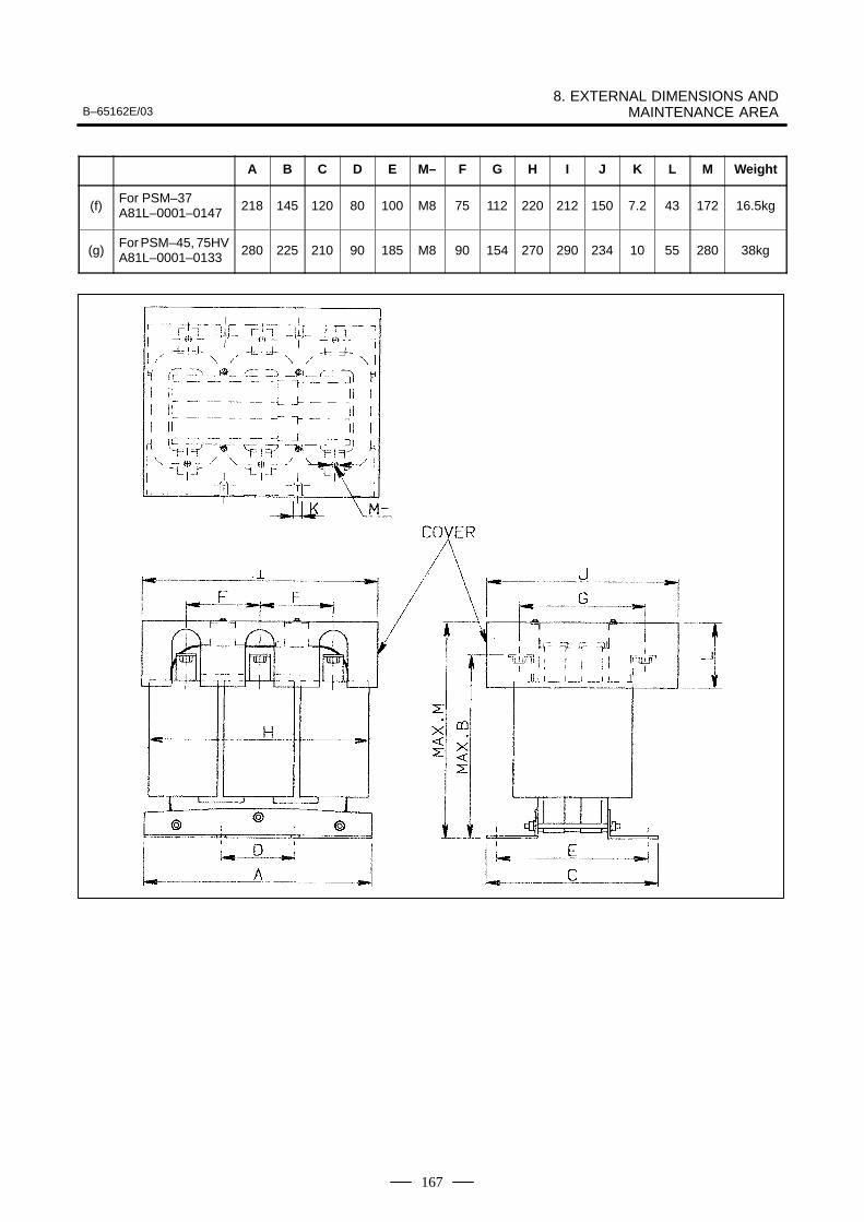
B–65162E/038. EXTERNAL DIMENSIONS AND
MAINTENANCE AREA
167
A B C D E M– F G H I J K L M Weight
(f)For PSM–37A81L–0001–0147 218 145 120 80 100 M8 75 112 220 212 150 7.2 43 172 16.5kg
(g)For PSM–45, 75HVA81L–0001–0133 280 225 210 90 185 M8 90 154 270 290 234 10 55 280 38kg
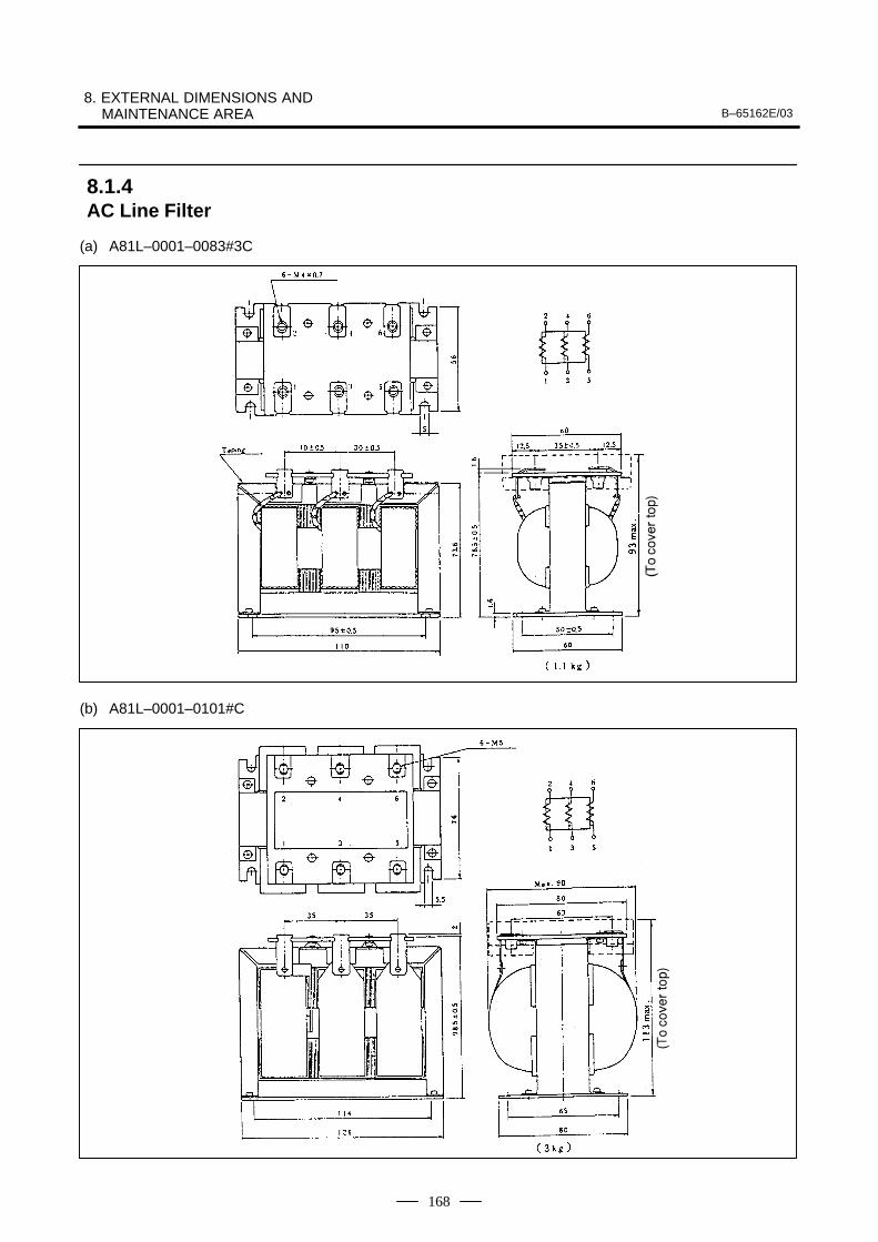
8. EXTERNAL DIMENSIONS AND MAINTENANCE AREA B–65162E/03
168
(a) A81L–0001–0083#3C
(b) A81L–0001–0101#C
8.1.4AC Line Filter
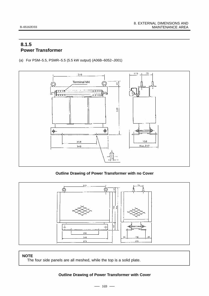
B–65162E/038. EXTERNAL DIMENSIONS AND
MAINTENANCE AREA
169
(a) For PSM–5.5, PSMR–5.5 (5.5 kW output) (A06B–6052–J001)
Terminal M4
Outline Drawing of Power Transformer with no Cover
NOTEThe four side panels are all meshed, while the top is a solid plate.
Outline Drawing of Power Transformer with Cover
8.1.5Power Transformer
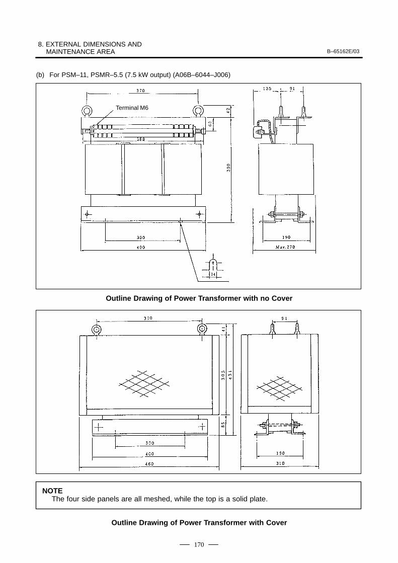
8. EXTERNAL DIMENSIONS AND MAINTENANCE AREA B–65162E/03
170
(b) For PSM–11, PSMR–5.5 (7.5 kW output) (A06B–6044–J006)
Terminal M6
Outline Drawing of Power Transformer with no Cover
NOTEThe four side panels are all meshed, while the top is a solid plate.
Outline Drawing of Power Transformer with Cover
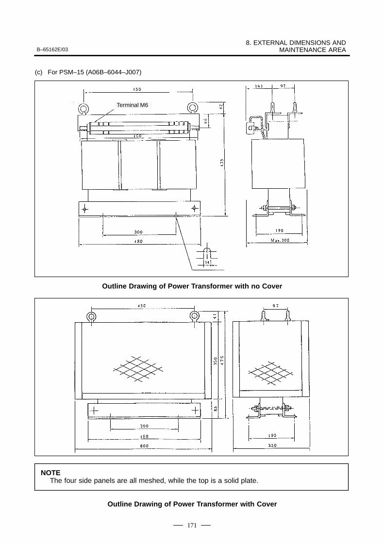
B–65162E/038. EXTERNAL DIMENSIONS AND
MAINTENANCE AREA
171
(c) For PSM–15 (A06B–6044–J007)
Terminal M6
Outline Drawing of Power Transformer with no Cover
NOTEThe four side panels are all meshed, while the top is a solid plate.
Outline Drawing of Power Transformer with Cover
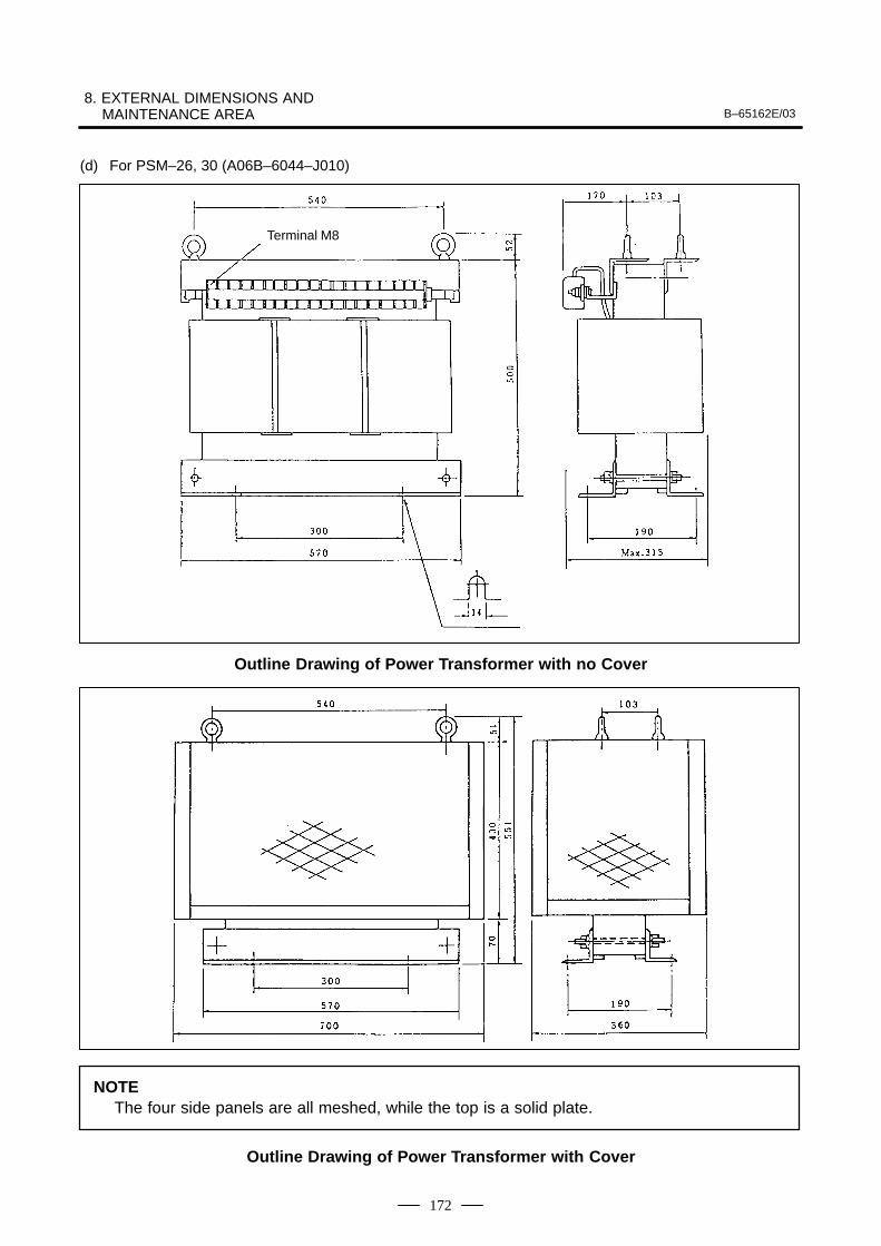
8. EXTERNAL DIMENSIONS AND MAINTENANCE AREA B–65162E/03
172
(d) For PSM–26, 30 (A06B–6044–J010)
Terminal M8
Outline Drawing of Power Transformer with no Cover
NOTEThe four side panels are all meshed, while the top is a solid plate.
Outline Drawing of Power Transformer with Cover
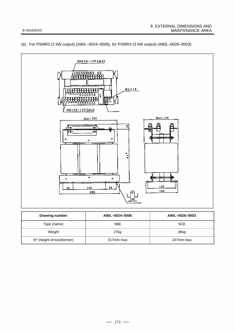
B–65162E/038. EXTERNAL DIMENSIONS AND
MAINTENANCE AREA
173
(e) For PSMR3 (2 kW output) (A80L–0024–0006), for PSMR3 (3 kW output) (A80L–0026–0003)
Drawing number A80L–0024–0006 A80L–0026–0003
Type (name) SBE SCE
Weight 27kg 36kg
hl* (height of transformer) 217mm max 247mm max
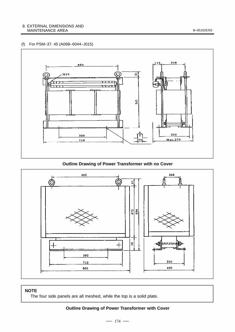
8. EXTERNAL DIMENSIONS AND MAINTENANCE AREA B–65162E/03
174
(f) For PSM–37. 45 (A06B–6044–J015)
Outline Drawing of Power Transformer with no Cover
NOTEThe four side panels are all meshed, while the top is a solid plate.
Outline Drawing of Power Transformer with Cover
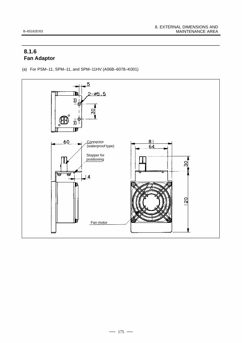
B–65162E/038. EXTERNAL DIMENSIONS AND
MAINTENANCE AREA
175
(a) For PSM–11, SPM–11, and SPM–11HV (A06B–6078–K001)
Connector (waterproof type)
Stopper for positioning
Fan motor
8.1.6Fan Adaptor
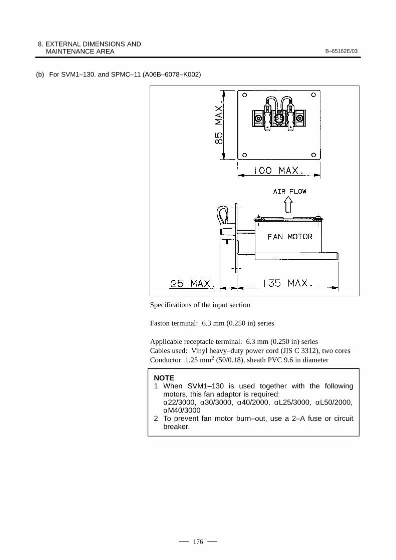
8. EXTERNAL DIMENSIONS AND MAINTENANCE AREA B–65162E/03
176
(b) For SVM1–130. and SPMC–11 (A06B–6078–K002)
Specifications of the input section
Faston terminal: 6.3 mm (0.250 in) series
Applicable receptacle terminal: 6.3 mm (0.250 in) seriesCables used: Vinyl heavy–duty power cord (JIS C 3312), two coresConductor 1.25 mm2 (50/0.18), sheath PVC 9.6 in diameter
NOTE1 When SVM1–130 is used together with the following
motors, this fan adaptor is required:α22/3000, α30/3000, α40/2000, αL25/3000, αL50/2000,αM40/3000
2 To prevent fan motor burn–out, use a 2–A fuse or circuitbreaker.
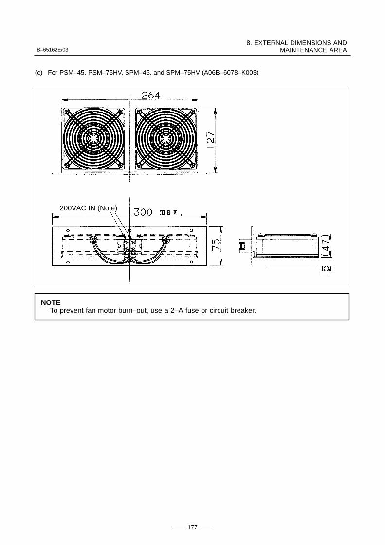
B–65162E/038. EXTERNAL DIMENSIONS AND
MAINTENANCE AREA
177
(c) For PSM–45, PSM–75HV, SPM–45, and SPM–75HV (A06B–6078–K003)
200VAC IN (Note)
NOTETo prevent fan motor burn–out, use a 2–A fuse or circuit breaker.
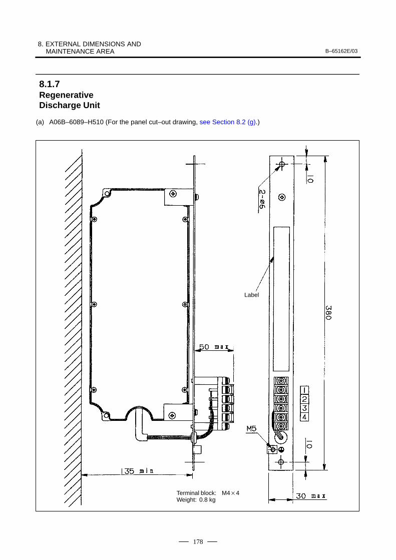
8. EXTERNAL DIMENSIONS AND MAINTENANCE AREA B–65162E/03
178
(a) A06B–6089–H510 (For the panel cut–out drawing, see Section 8.2 (g).)
Label
Terminal block: M44Weight: 0.8 kg
8.1.7RegenerativeDischarge Unit
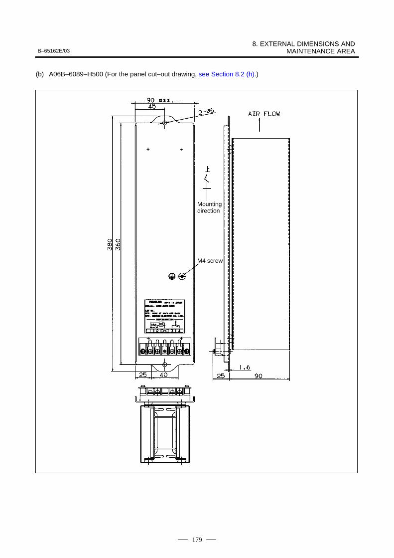
B–65162E/038. EXTERNAL DIMENSIONS AND
MAINTENANCE AREA
179
(b) A06B–6089–H500 (For the panel cut–out drawing, see Section 8.2 (h).)
Mountingdirection
M4 screw
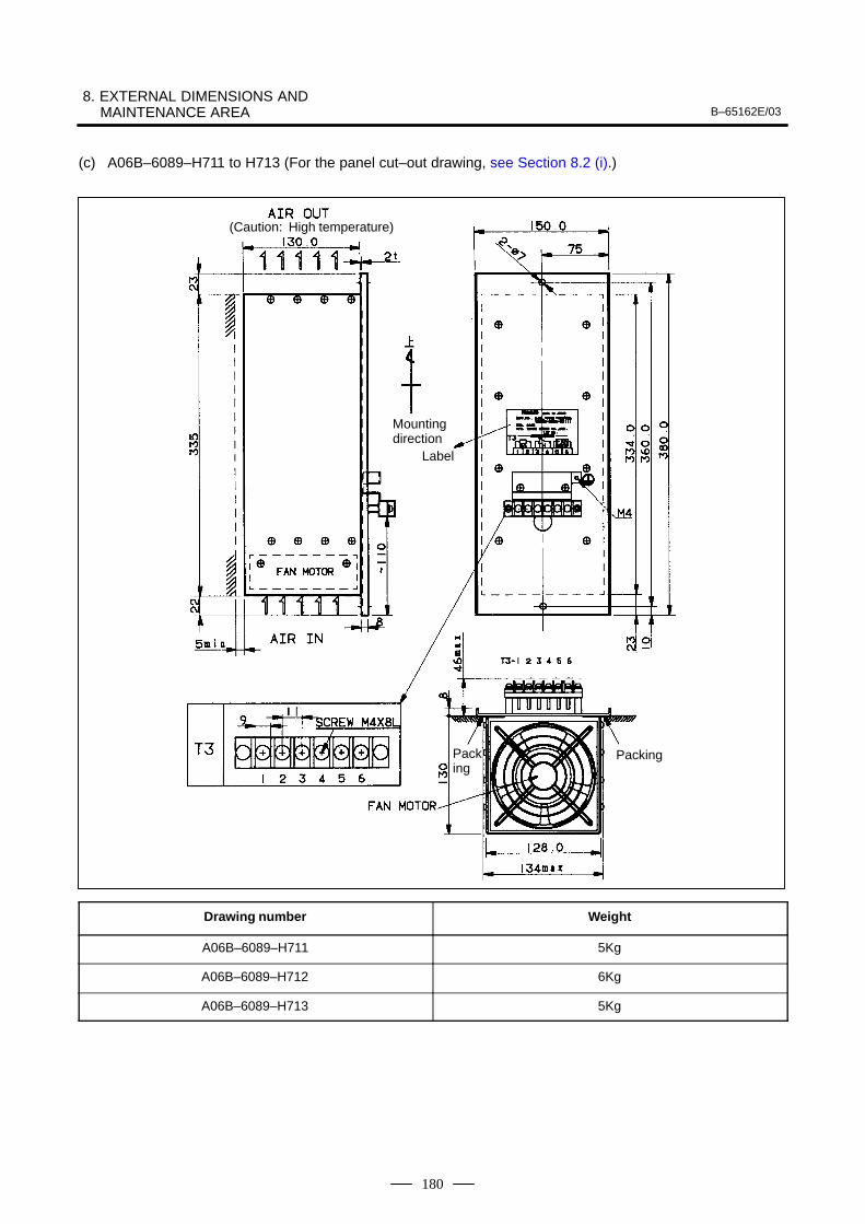
8. EXTERNAL DIMENSIONS AND MAINTENANCE AREA B–65162E/03
180
(c) A06B–6089–H711 to H713 (For the panel cut–out drawing, see Section 8.2 (i).)
Packing
Packing
(Caution: High temperature)
Mounting direction
Label
Drawing number Weight
A06B–6089–H711 5Kg
A06B–6089–H712 6Kg
A06B–6089–H713 5Kg
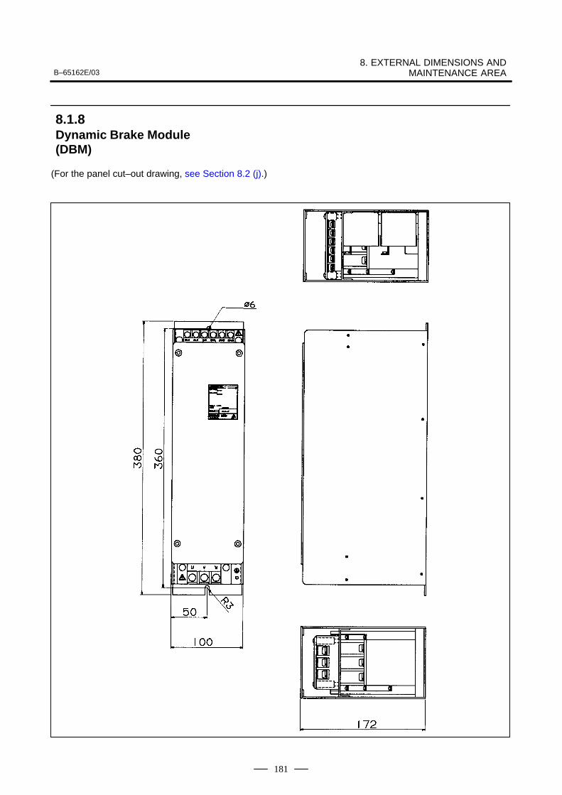
B–65162E/038. EXTERNAL DIMENSIONS AND
MAINTENANCE AREA
181
(For the panel cut–out drawing, see Section 8.2 (j).)
8.1.8Dynamic Brake Module(DBM)
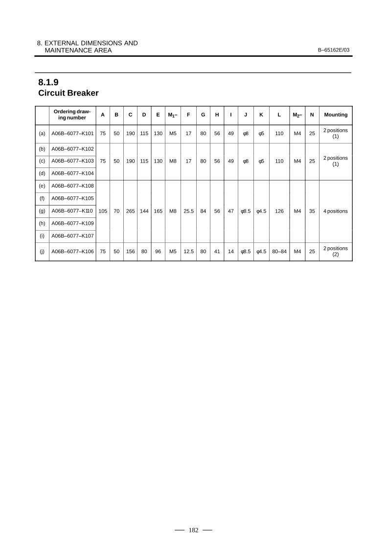
8. EXTERNAL DIMENSIONS AND MAINTENANCE AREA B–65162E/03
182
Ordering draw-ing number A B C D E M1– F G H I J K L M2– N Mounting
(a) A06B–6077–K101 75 50 190 115 130 M5 17 80 56 49 φ8 φ5 110 M4 252 positions
(1)
(b) A06B–6077–K102
(c) A06B–6077–K103 75 50 190 115 130 M8 17 80 56 49 φ8 φ5 110 M4 252 positions
(1)
(d) A06B–6077–K104
( )
(e) A06B–6077–K108
(f) A06B–6077–K105
(g) A06B–6077–K110 105 70 265 144 165 M8 25.5 84 56 47 φ8.5 φ4.5 126 M4 35 4 positions
(h) A06B–6077–K109
(i) A06B–6077–K107
(j) A06B–6077–K106 75 50 156 80 96 M5 12.5 80 41 14 φ8.5 φ4.5 80–84 M4 252 positions
(2)
8.1.9Circuit Breaker
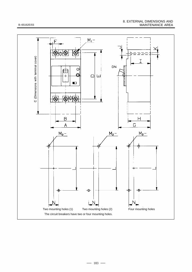
B–65162E/038. EXTERNAL DIMENSIONS AND
MAINTENANCE AREA
183
Two mounting holes (1) Two mounting holes (2) Four mounting holes
The circuit breakers have two or four mounting holes.
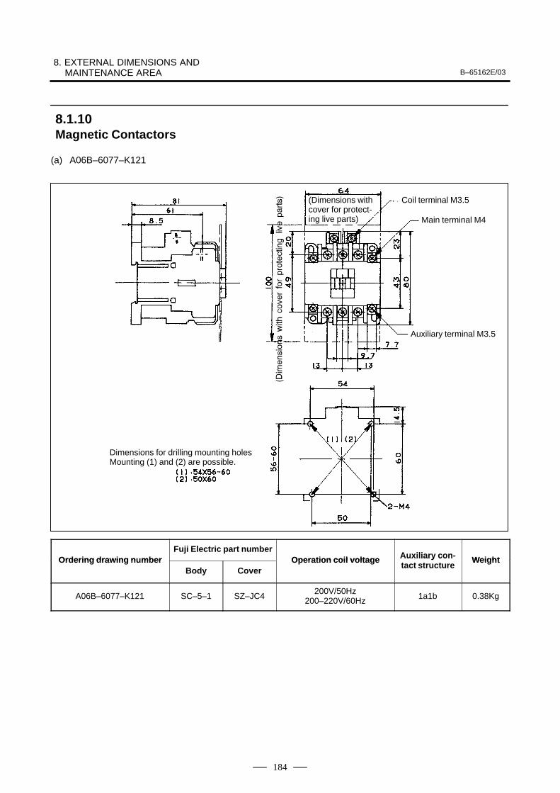
8. EXTERNAL DIMENSIONS AND MAINTENANCE AREA B–65162E/03
184
(a) A06B–6077–K121
(Dimensions withcover for protect-ing live parts)
Coil terminal M3.5
Main terminal M4
Auxiliary terminal M3.5
Dimensions for drilling mounting holesMounting (1) and (2) are possible.
Ordering drawing n mberFuji Electric part number
Operation coil voltage Auxiliary con- WeightOrdering drawing numberBody Cover
Operation coil voltage Auxiliary contact structure
Weight
A06B–6077–K121 SC–5–1 SZ–JC4200V/50Hz
200–220V/60Hz 1a1b 0.38Kg
8.1.10Magnetic Contactors
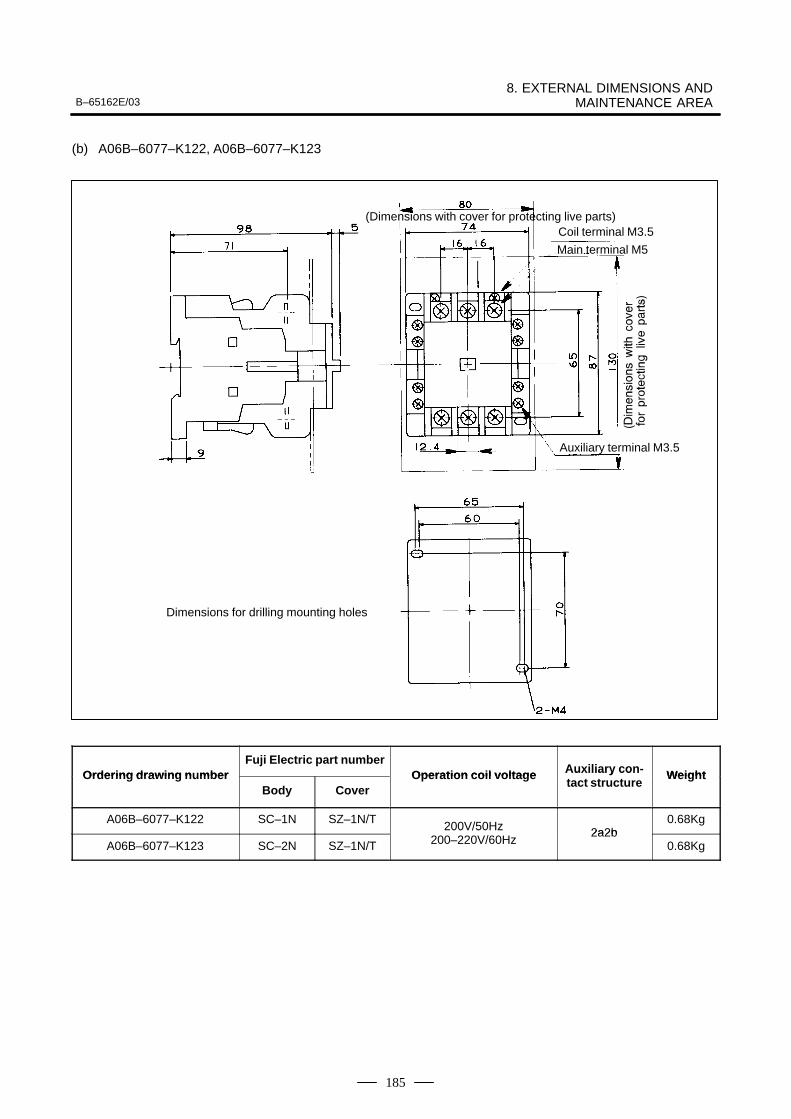
B–65162E/038. EXTERNAL DIMENSIONS AND
MAINTENANCE AREA
185
(b) A06B–6077–K122, A06B–6077–K123
(Dimensions with cover for protecting live parts)Coil terminal M3.5
Main terminal M5
Auxiliary terminal M3.5
Dimensions for drilling mounting holes
Ordering drawing n mberFuji Electric part number
Operation coil voltage Auxiliary con- WeightOrdering drawing numberBody Cover
Operation coil voltage Auxiliary contact structure
Weight
A06B–6077–K122 SC–1N SZ–1N/T200V/50Hz 2a2b
0.68Kg
A06B–6077–K123 SC–2N SZ–1N/T
200V/50Hz200–220V/60Hz
2a2b0.68Kg
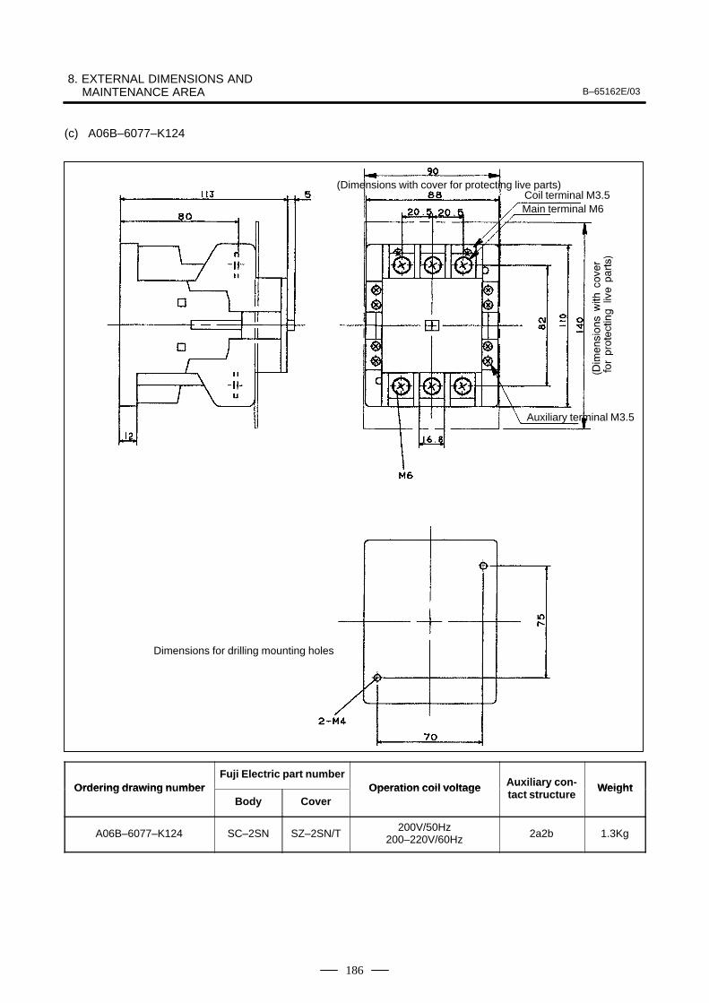
8. EXTERNAL DIMENSIONS AND MAINTENANCE AREA B–65162E/03
186
(c) A06B–6077–K124
(Dimensions with cover for protecting live parts)Coil terminal M3.5Main terminal M6
Auxiliary terminal M3.5
Dimensions for drilling mounting holes
Ordering drawing n mberFuji Electric part number
Operation coil voltage Auxiliary con- WeightOrdering drawing numberBody Cover
Operation coil voltage Auxiliary contact structure
Weight
A06B–6077–K124 SC–2SN SZ–2SN/T200V/50Hz
200–220V/60Hz 2a2b 1.3Kg
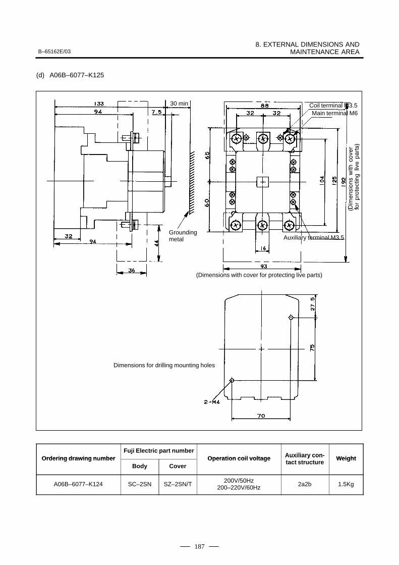
B–65162E/038. EXTERNAL DIMENSIONS AND
MAINTENANCE AREA
187
(d) A06B–6077–K125
(Dimensions with cover for protecting live parts)
Coil terminal M3.5Main terminal M6
Auxiliary terminal M3.5
Dimensions for drilling mounting holes
30 min
Groundingmetal
Ordering drawing n mberFuji Electric part number
Operation coil voltage Auxiliary con- WeightOrdering drawing numberBody Cover
Operation coil voltage Auxiliary contact structure
Weight
A06B–6077–K124 SC–2SN SZ–2SN/T200V/50Hz
200–220V/60Hz 2a2b 1.5Kg
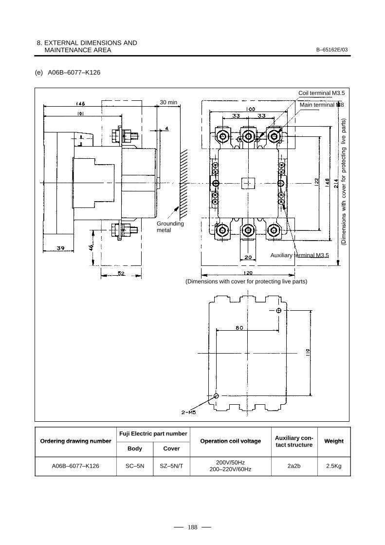
8. EXTERNAL DIMENSIONS AND MAINTENANCE AREA B–65162E/03
188
(e) A06B–6077–K126
(Dimensions with cover for protecting live parts)
Coil terminal M3.5
Main terminal M8
Auxiliary terminal M3.5
30 min
Groundingmetal
Ordering drawing n mberFuji Electric part number
Operation coil voltage Auxiliary con- WeightOrdering drawing numberBody Cover
Operation coil voltage Auxiliary contact structure
Weight
A06B–6077–K126 SC–5N SZ–5N/T200V/50Hz
200–220V/60Hz 2a2b 2.5Kg
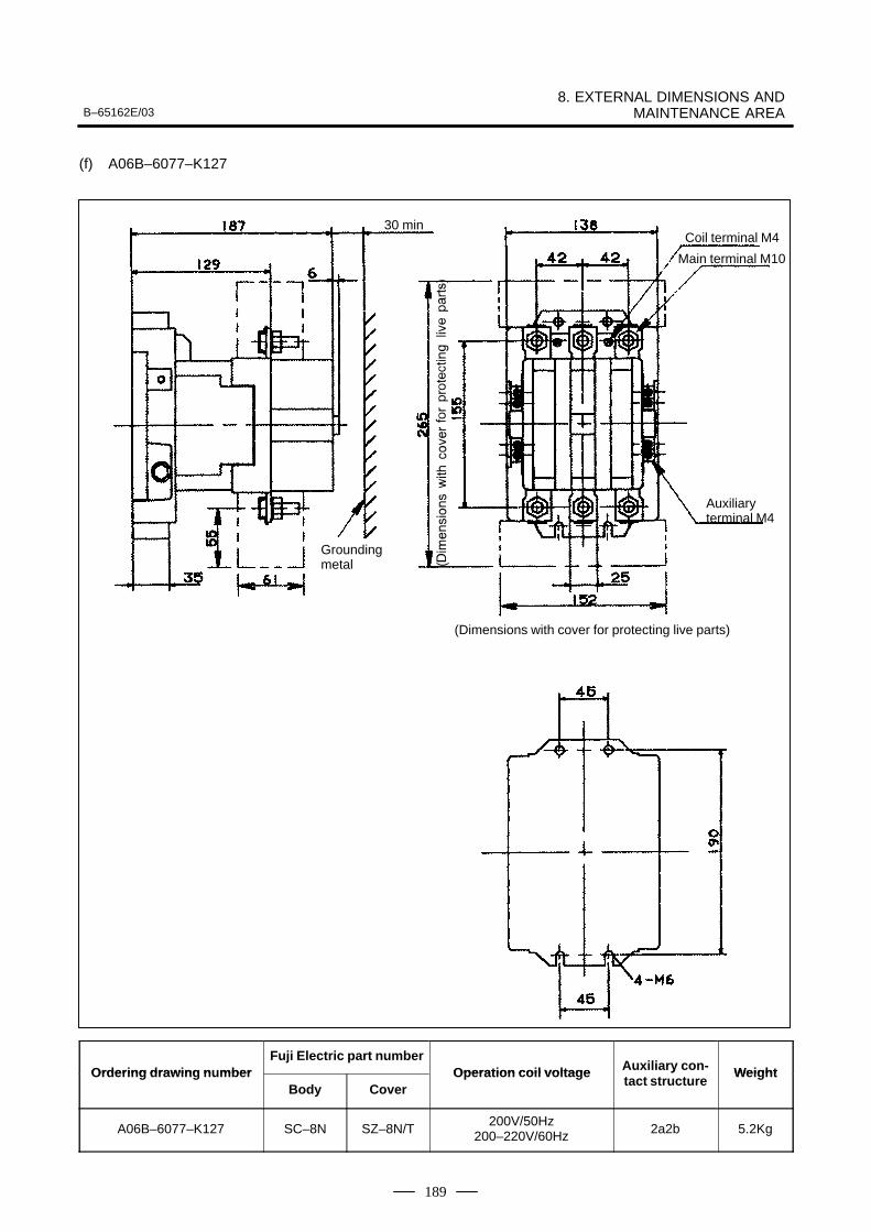
B–65162E/038. EXTERNAL DIMENSIONS AND
MAINTENANCE AREA
189
(f) A06B–6077–K127
(Dimensions with cover for protecting live parts)
Coil terminal M4
Main terminal M10
Auxiliary terminal M4
30 min
Groundingmetal
Ordering drawing n mberFuji Electric part number
Operation coil voltage Auxiliary con- WeightOrdering drawing numberBody Cover
Operation coil voltage Auxiliary contact structure
Weight
A06B–6077–K127 SC–8N SZ–8N/T200V/50Hz
200–220V/60Hz 2a2b 5.2Kg
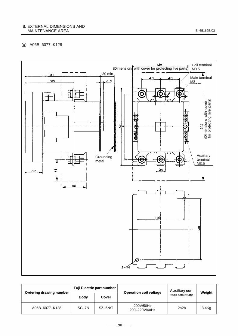
8. EXTERNAL DIMENSIONS AND MAINTENANCE AREA B–65162E/03
190
(g) A06B–6077–K128
(Dimensions with cover for protecting live parts)Coil terminal M3.5
Main terminal M8
Auxiliary terminalM3.5
30 min
Groundingmetal
Ordering drawing n mberFuji Electric part number
Operation coil voltage Auxiliary con- WeightOrdering drawing numberBody Cover
Operation coil voltage Auxiliary contact structure
Weight
A06B–6077–K128 SC–7N SZ–5N/T200V/50Hz
200–220V/60Hz 2a2b 3.4Kg
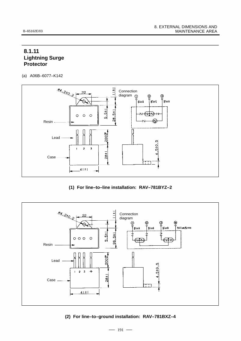
B–65162E/038. EXTERNAL DIMENSIONS AND
MAINTENANCE AREA
191
(a) A06B–6077–K142
Connectiondiagram
Resin
Lead
Case
(1) For line–to–line installation: RAV–781BYZ–2
Connectiondiagram
Resin
Lead
Case
(2) For line–to–ground installation: RAV–781BXZ–4
8.1.11Lightning SurgeProtector

8. EXTERNAL DIMENSIONS AND MAINTENANCE AREA B–65162E/03
192
Specification Rated voltage Clamp voltage Surge withstand current Surge withstand voltage
R⋅A⋅V–781BYZ–2 AC250V DC783V10% (V1.0) 2500A (8/20µS) 20kV (1.2/50µS)
Specification Rated voltage Clamp voltage Surge withstand current Surge withstand voltage
R⋅A⋅V–781BXZ–4
line–to–line:430VAC,
line–to–ground:250VAC
AC700V20% (Ua) 2500A (8/20µS) 2.0kV (1.2/50µS)
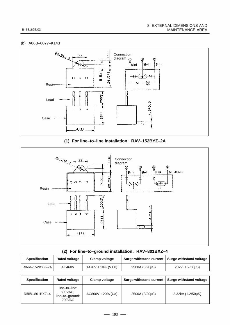
B–65162E/038. EXTERNAL DIMENSIONS AND
MAINTENANCE AREA
193
(b) A06B–6077–K143
Connectiondiagram
Resin
Lead
Case
(1) For line–to–line installation: RAV–152BYZ–2A
Connectiondiagram
Resin
Lead
Case
(2) For line–to–ground installation: RAV–801BXZ–4
Specification Rated voltage Clamp voltage Surge withstand current Surge withstand voltage
R⋅A⋅V–152BYZ–2A AC460V 1470V10% (V1.0) 2500A (8/20µS) 20kV (1.2/50µS)
Specification Rated voltage Clamp voltage Surge withstand current Surge withstand voltage
R⋅A⋅V–801BXZ–4
line–to–line:500VAC,
line–to–ground:290VAC
AC800V20% (Ua) 2500A (8/20µS) 2.32kV (1.2/50µS)
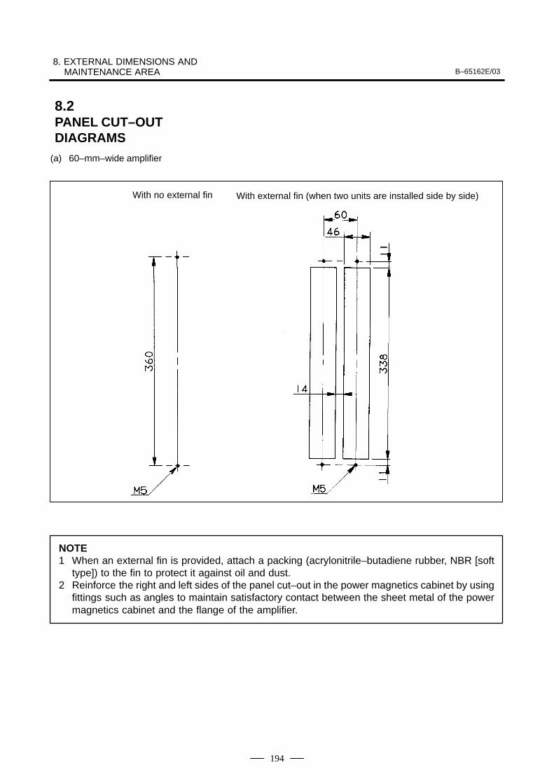
8. EXTERNAL DIMENSIONS AND MAINTENANCE AREA B–65162E/03
194
(a) 60–mm–wide amplifier
With no external fin With external fin (when two units are installed side by side)
NOTE1 When an external fin is provided, attach a packing (acrylonitrile–butadiene rubber, NBR [soft
type]) to the fin to protect it against oil and dust.2 Reinforce the right and left sides of the panel cut–out in the power magnetics cabinet by using
fittings such as angles to maintain satisfactory contact between the sheet metal of the powermagnetics cabinet and the flange of the amplifier.
8.2PANEL CUT–OUT DIAGRAMS
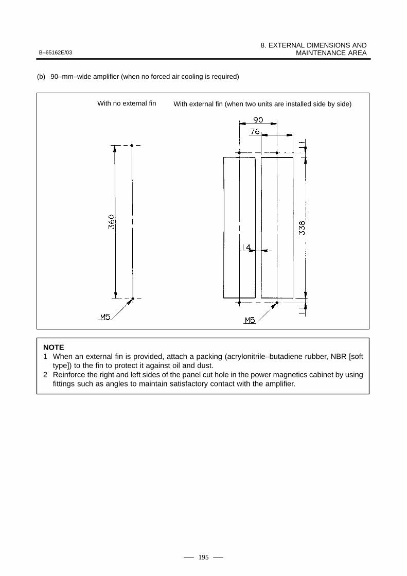
B–65162E/038. EXTERNAL DIMENSIONS AND
MAINTENANCE AREA
195
(b) 90–mm–wide amplifier (when no forced air cooling is required)
With no external fin With external fin (when two units are installed side by side)
NOTE1 When an external fin is provided, attach a packing (acrylonitrile–butadiene rubber, NBR [soft
type]) to the fin to protect it against oil and dust.2 Reinforce the right and left sides of the panel cut hole in the power magnetics cabinet by using
fittings such as angles to maintain satisfactory contact with the amplifier.
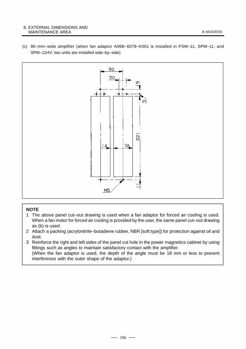
8. EXTERNAL DIMENSIONS AND MAINTENANCE AREA B–65162E/03
196
(c) 90–mm–wide amplifier (when fan adaptor A06B–6078–K001 is installed in PSM–11, SPM–11, and
SPM–11HV; two units are installed side–by–side)
NOTE1 The above panel cut–out drawing is used when a fan adaptor for forced air cooling is used.
When a fan motor for forced air cooling is provided by the user, the same panel cut–out drawingas (b) is used.
2 Attach a packing (acrylonitrile–butadiene rubber, NBR [soft type]) for protection against oil anddust.
3 Reinforce the right and left sides of the panel cut hole in the power magnetics cabinet by usingfittings such as angles to maintain satisfactory contact with the amplifier.(When the fan adaptor is used, the depth of the angle must be 18 mm or less to preventinterference with the outer shape of the adaptor.)
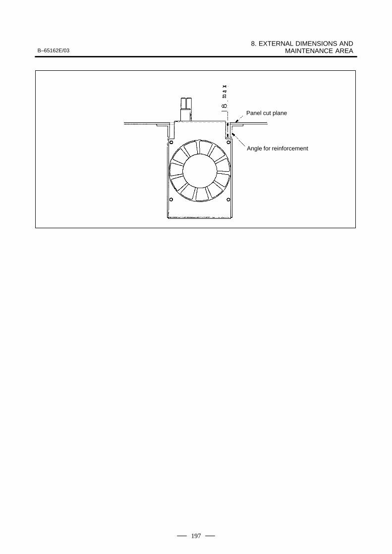
B–65162E/038. EXTERNAL DIMENSIONS AND
MAINTENANCE AREA
197
Panel cut plane
Angle for reinforcement
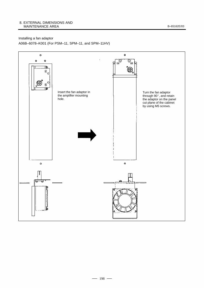
8. EXTERNAL DIMENSIONS AND MAINTENANCE AREA B–65162E/03
198
Installing a fan adaptor
A06B–6078–K001 (For PSM–11, SPM–11, and SPM–11HV)
Insert the fan adaptor inthe amplifier mountinghole.
Turn the fan adaptorthrough 90, and retainthe adaptor on the panelcut plane of the cabinetby using M5 screws.
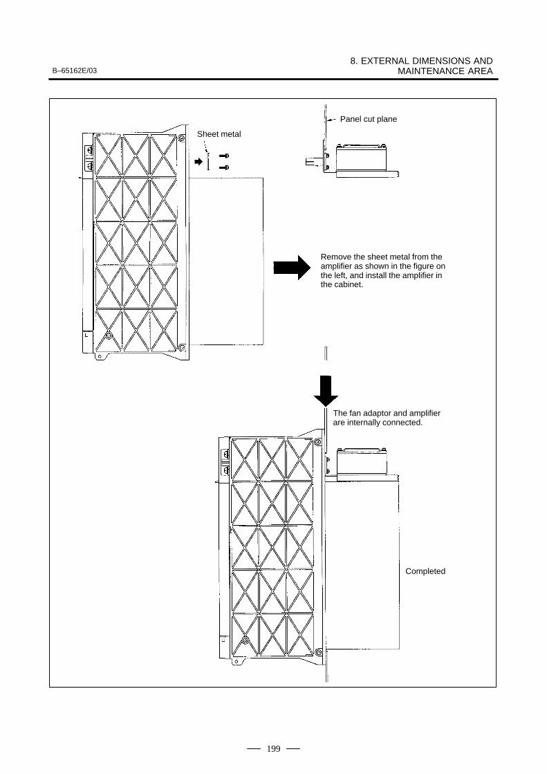
B–65162E/038. EXTERNAL DIMENSIONS AND
MAINTENANCE AREA
199
Sheet metal
Panel cut plane
Remove the sheet metal from theamplifier as shown in the figure onthe left, and install the amplifier inthe cabinet.
The fan adaptor and amplifierare internally connected.
Completed
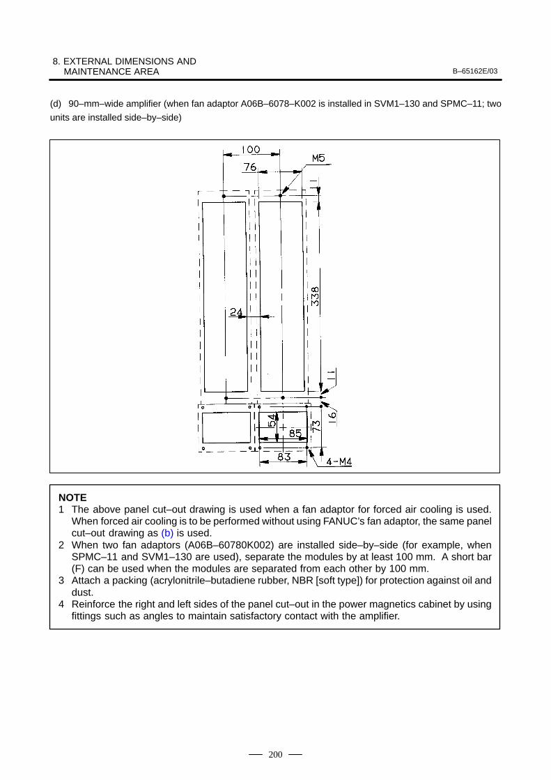
8. EXTERNAL DIMENSIONS AND MAINTENANCE AREA B–65162E/03
200
(d) 90–mm–wide amplifier (when fan adaptor A06B–6078–K002 is installed in SVM1–130 and SPMC–11; two
units are installed side–by–side)
NOTE1 The above panel cut–out drawing is used when a fan adaptor for forced air cooling is used.
When forced air cooling is to be performed without using FANUC’s fan adaptor, the same panelcut–out drawing as (b) is used.
2 When two fan adaptors (A06B–60780K002) are installed side–by–side (for example, whenSPMC–11 and SVM1–130 are used), separate the modules by at least 100 mm. A short bar(F) can be used when the modules are separated from each other by 100 mm.
3 Attach a packing (acrylonitrile–butadiene rubber, NBR [soft type]) for protection against oil anddust.
4 Reinforce the right and left sides of the panel cut–out in the power magnetics cabinet by usingfittings such as angles to maintain satisfactory contact with the amplifier.
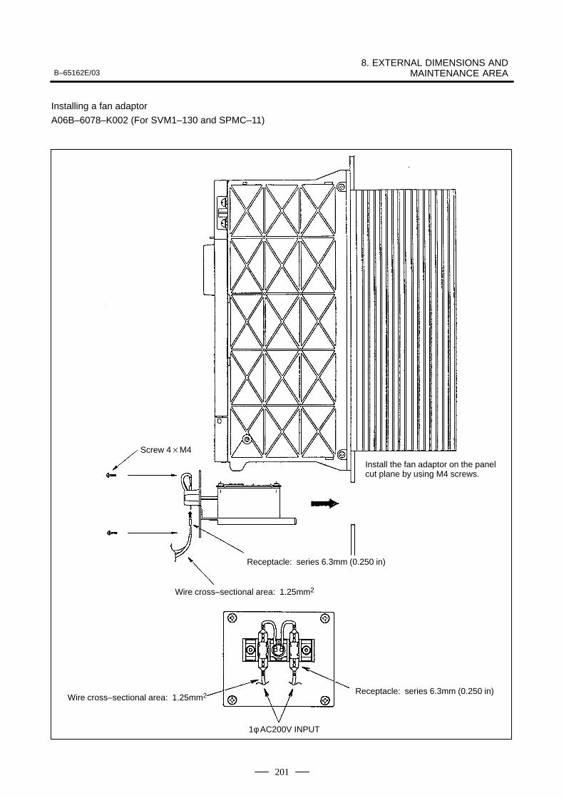
B–65162E/038. EXTERNAL DIMENSIONS AND
MAINTENANCE AREA
201
Installing a fan adaptor
A06B–6078–K002 (For SVM1–130 and SPMC–11)
Screw 4M4
Receptacle: series 6.3mm (0.250 in)
Wire cross–sectional area: 1.25mm2
Wire cross–sectional area: 1.25mm2 Receptacle: series 6.3mm (0.250 in)
Install the fan adaptor on the panelcut plane by using M4 screws.
1φ AC200V INPUT
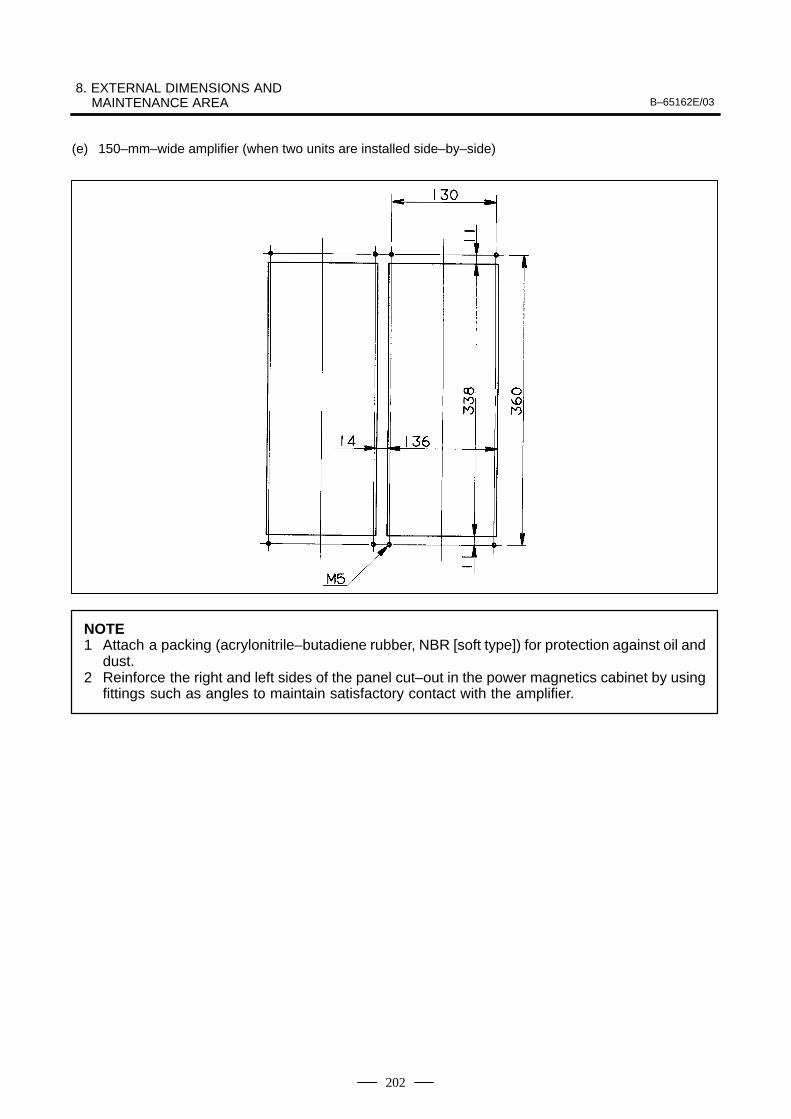
8. EXTERNAL DIMENSIONS AND MAINTENANCE AREA B–65162E/03
202
(e) 150–mm–wide amplifier (when two units are installed side–by–side)
NOTE1 Attach a packing (acrylonitrile–butadiene rubber, NBR [soft type]) for protection against oil and
dust.2 Reinforce the right and left sides of the panel cut–out in the power magnetics cabinet by using
fittings such as angles to maintain satisfactory contact with the amplifier.
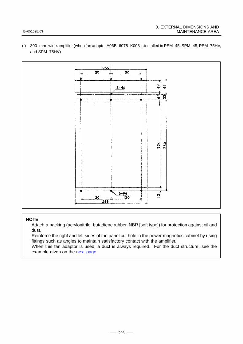
B–65162E/038. EXTERNAL DIMENSIONS AND
MAINTENANCE AREA
203
(f) 300–mm–wide amplifier (when fan adaptor A06B–6078–K003 is installed in PSM–45, SPM–45, PSM–75HV,
and SPM–75HV)
NOTEAttach a packing (acrylonitrile–butadiene rubber, NBR [soft type]) for protection against oil anddust.Reinforce the right and left sides of the panel cut hole in the power magnetics cabinet by usingfittings such as angles to maintain satisfactory contact with the amplifier.When this fan adaptor is used, a duct is always required. For the duct structure, see theexample given on the next page.
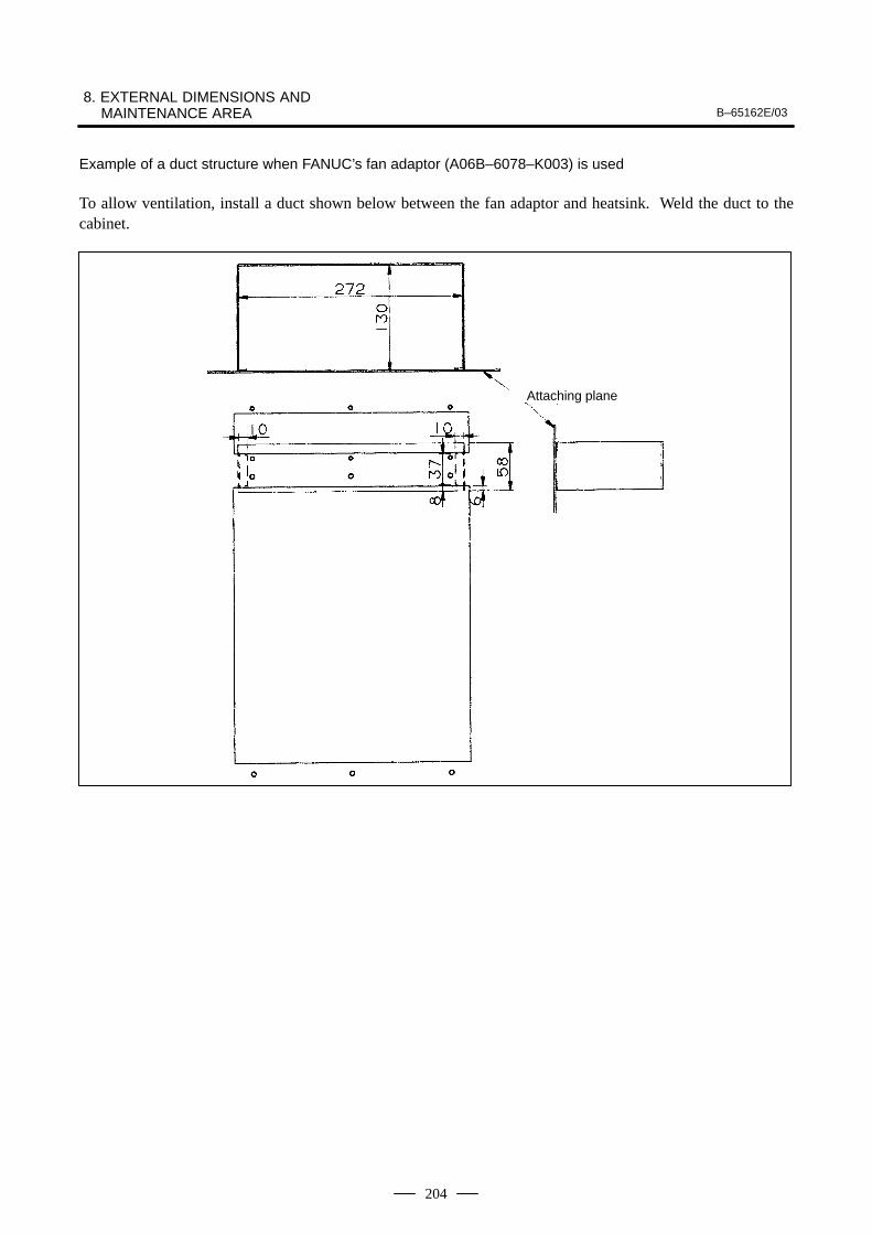
8. EXTERNAL DIMENSIONS AND MAINTENANCE AREA B–65162E/03
204
Example of a duct structure when FANUC’s fan adaptor (A06B–6078–K003) is used
To allow ventilation, install a duct shown below between the fan adaptor and heatsink. Weld the duct to thecabinet.
Attaching plane
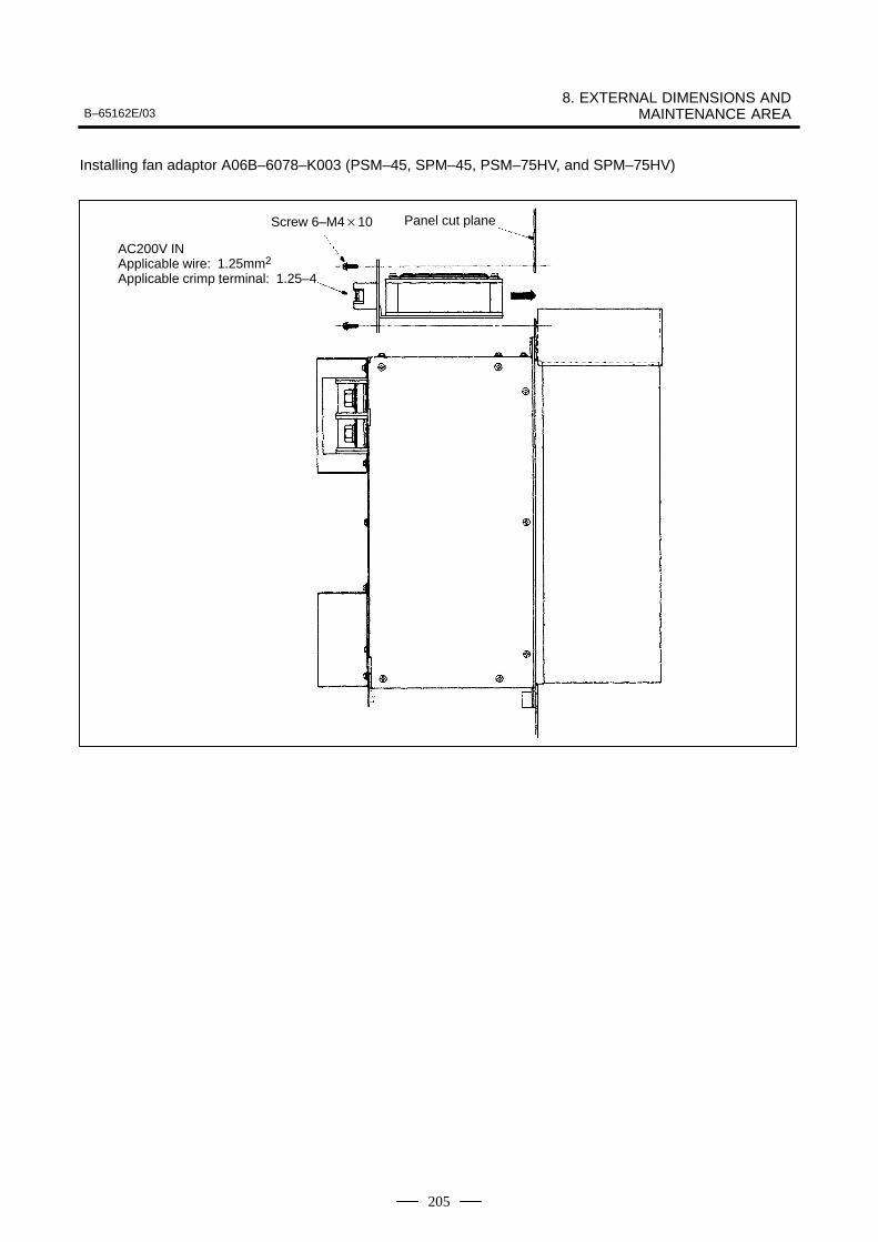
B–65162E/038. EXTERNAL DIMENSIONS AND
MAINTENANCE AREA
205
Installing fan adaptor A06B–6078–K003 (PSM–45, SPM–45, PSM–75HV, and SPM–75HV)
Screw 6–M410 Panel cut plane
AC200V INApplicable wire: 1.25mm2
Applicable crimp terminal: 1.25–4
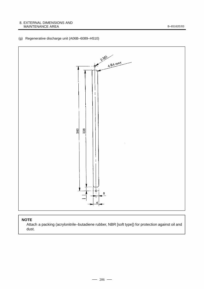
8. EXTERNAL DIMENSIONS AND MAINTENANCE AREA B–65162E/03
206
(g) Regenerative discharge unit (A06B–6089–H510)
NOTEAttach a packing (acrylonitrile–butadiene rubber, NBR [soft type]) for protection against oil anddust.
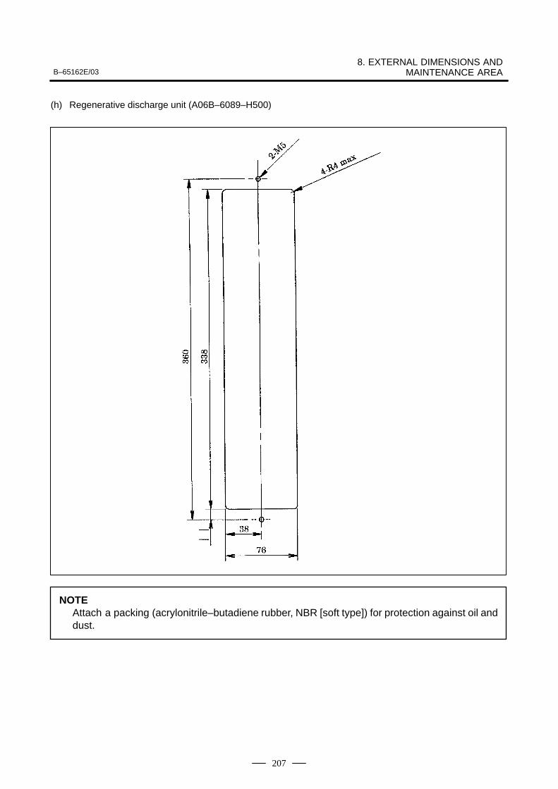
B–65162E/038. EXTERNAL DIMENSIONS AND
MAINTENANCE AREA
207
(h) Regenerative discharge unit (A06B–6089–H500)
NOTEAttach a packing (acrylonitrile–butadiene rubber, NBR [soft type]) for protection against oil anddust.
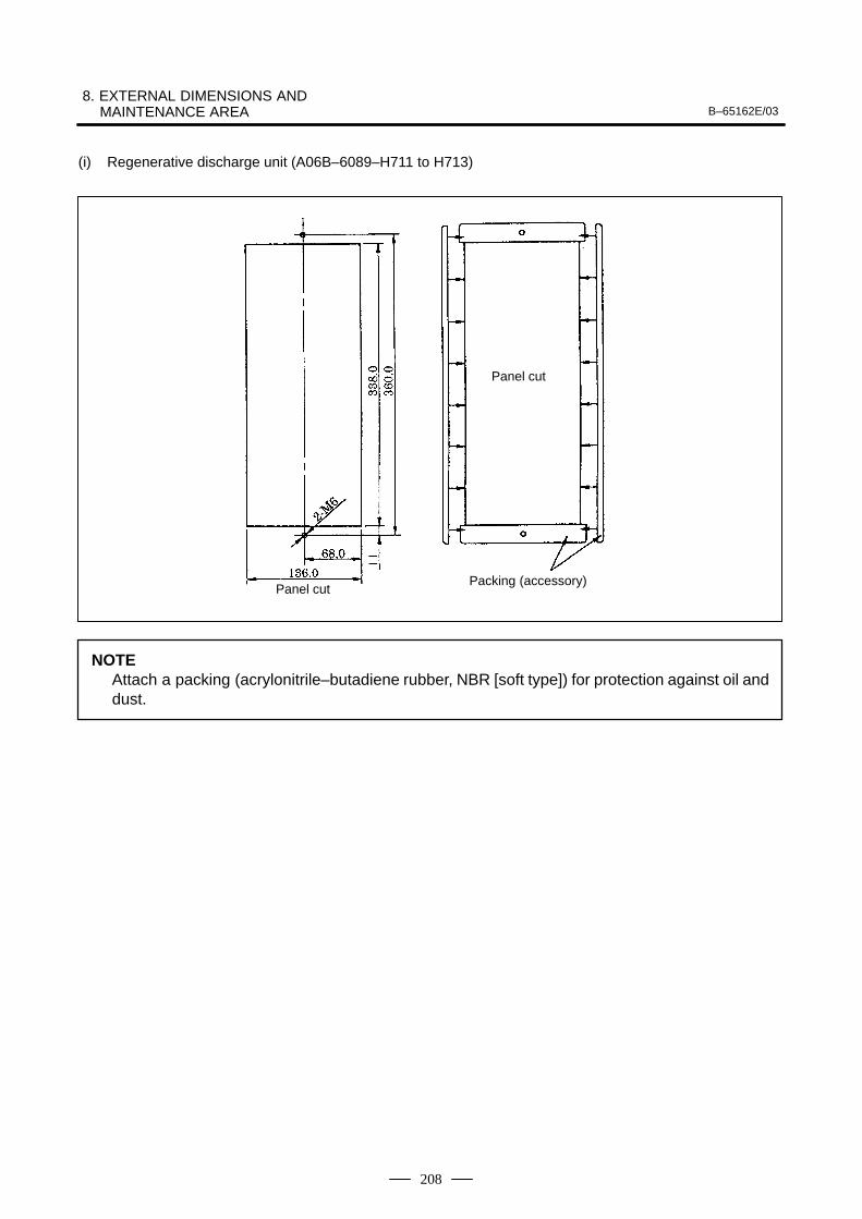
8. EXTERNAL DIMENSIONS AND MAINTENANCE AREA B–65162E/03
208
(i) Regenerative discharge unit (A06B–6089–H711 to H713)
Panel cut
Panel cutPacking (accessory)
NOTEAttach a packing (acrylonitrile–butadiene rubber, NBR [soft type]) for protection against oil anddust.
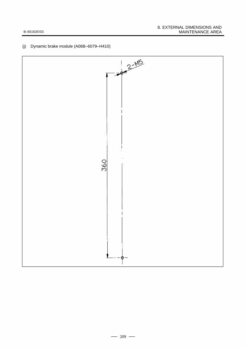
B–65162E/038. EXTERNAL DIMENSIONS AND
MAINTENANCE AREA
209
(j) Dynamic brake module (A06B–6079–H410)
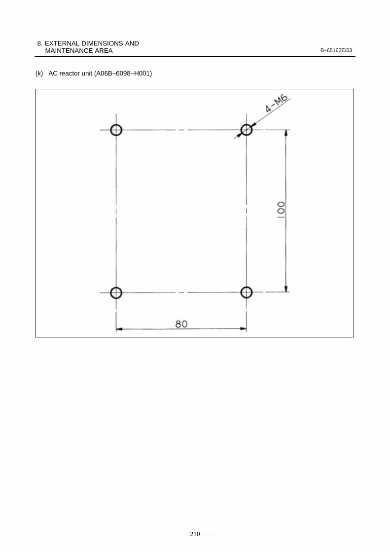
8. EXTERNAL DIMENSIONS AND MAINTENANCE AREA B–65162E/03
210
(k) AC reactor unit (A06B–6098–H001)
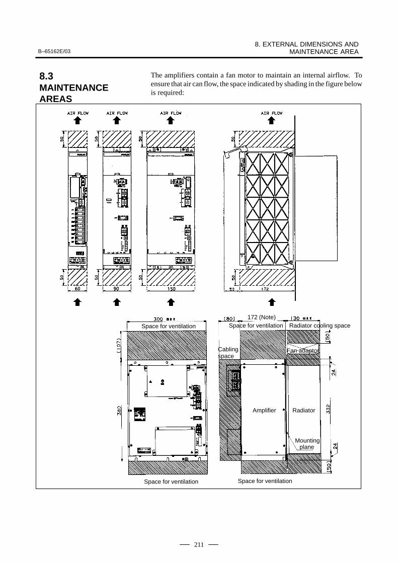
B–65162E/038. EXTERNAL DIMENSIONS AND
MAINTENANCE AREA
211
The amplifiers contain a fan motor to maintain an internal airflow. Toensure that air can flow, the space indicated by shading in the figure belowis required:
Space for ventilation Space for ventilation
Cablingspace
Space for ventilationSpace for ventilation Radiator cooling space
Fan adaptor
Amplifier Radiator
planeMounting
172 (Note)
8.3MAINTENANCEAREAS

9. CONNECTION B–65162E/03
212
9
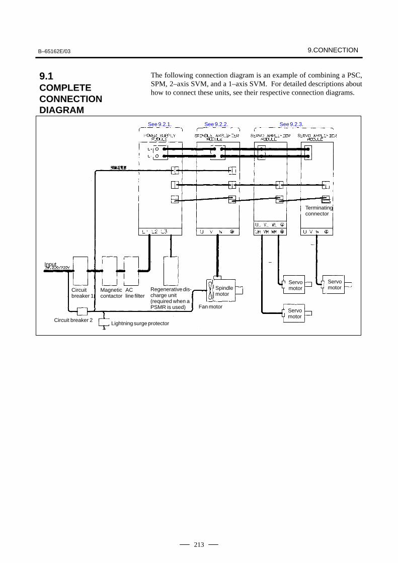
B–65162E/03 9.CONNECTION
213
The following connection diagram is an example of combining a PSC,SPM, 2–axis SVM, and a 1–axis SVM. For detailed descriptions abouthow to connect these units, see their respective connection diagrams.
See 9.2.1. See 9.2.2. See 9.2.3.
Terminatingconnector
Input
Circuitbreaker 1
Magneticcontactor
AC line filter
Regenerative dis-charge unit (required when aPSMR is used)
Spindlemotor
Servomotor
Servomotor
Servomotor
Circuit breaker 2
Fan motor
Lightning surge protector
9.1COMPLETECONNECTIONDIAGRAM
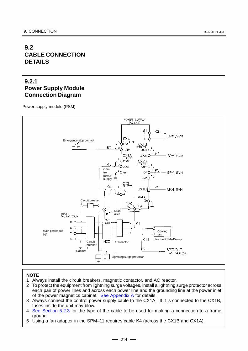
9. CONNECTION B–65162E/03
214
Power supply module (PSM)
Emergency stop contact
Con-trolpowersupply
Circuit breaker2
InputSparkkiller
Coil
Main power sup-ply
Coolingfan
Circuitbreaker1
AC reactorFor the PSM–45 only
Cabinet
Lightning surge protector
NOTE1 Always install the circuit breakers, magnetic contactor, and AC reactor.2 To protect the equipment from lightning surge voltages, install a lightning surge protector across
each pair of power lines and across each power line and the grounding line at the power inletof the power magnetics cabinet. See Appendix A for details.
3 Always connect the control power supply cable to the CX1A. If it is connected to the CX1B,fuses inside the unit may blow.
4 See Section 5.2.3 for the type of the cable to be used for making a connection to a frameground.
5 Using a fan adapter in the SPM–11 requires cable K4 (across the CX1B and CX1A).
9.2CABLE CONNECTIONDETAILS
9.2.1Power Supply ModuleConnection Diagram
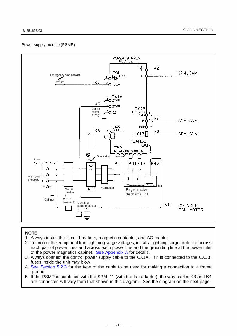
B–65162E/03 9.CONNECTION
215
Power supply module (PSMR)
Emergency stop contact
Controlpowersupply
Circuitbreaker 2
Coil
Main pow-er supply
Circuitbreaker1
AC reactor
CabinetLightningsurge protector
Spark killerInput
Thermostat Fan motorRegenerativedischarge unit
NOTE1 Always install the circuit breakers, magnetic contactor, and AC reactor.2 To protect the equipment from lightning surge voltages, install a lightning surge protector across
each pair of power lines and across each power line and the grounding line at the power inletof the power magnetics cabinet. See Appendix A for details.
3 Always connect the control power supply cable to the CX1A. If it is connected to the CX1B,fuses inside the unit may blow.
4 See Section 5.2.3 for the type of the cable to be used for making a connection to a frameground.
5 If the PSMR is combined with the SPM–11 (with the fan adapter), the way cables K3 and K4are connected will vary from that shown in this diagram. See the diagram on the next page.
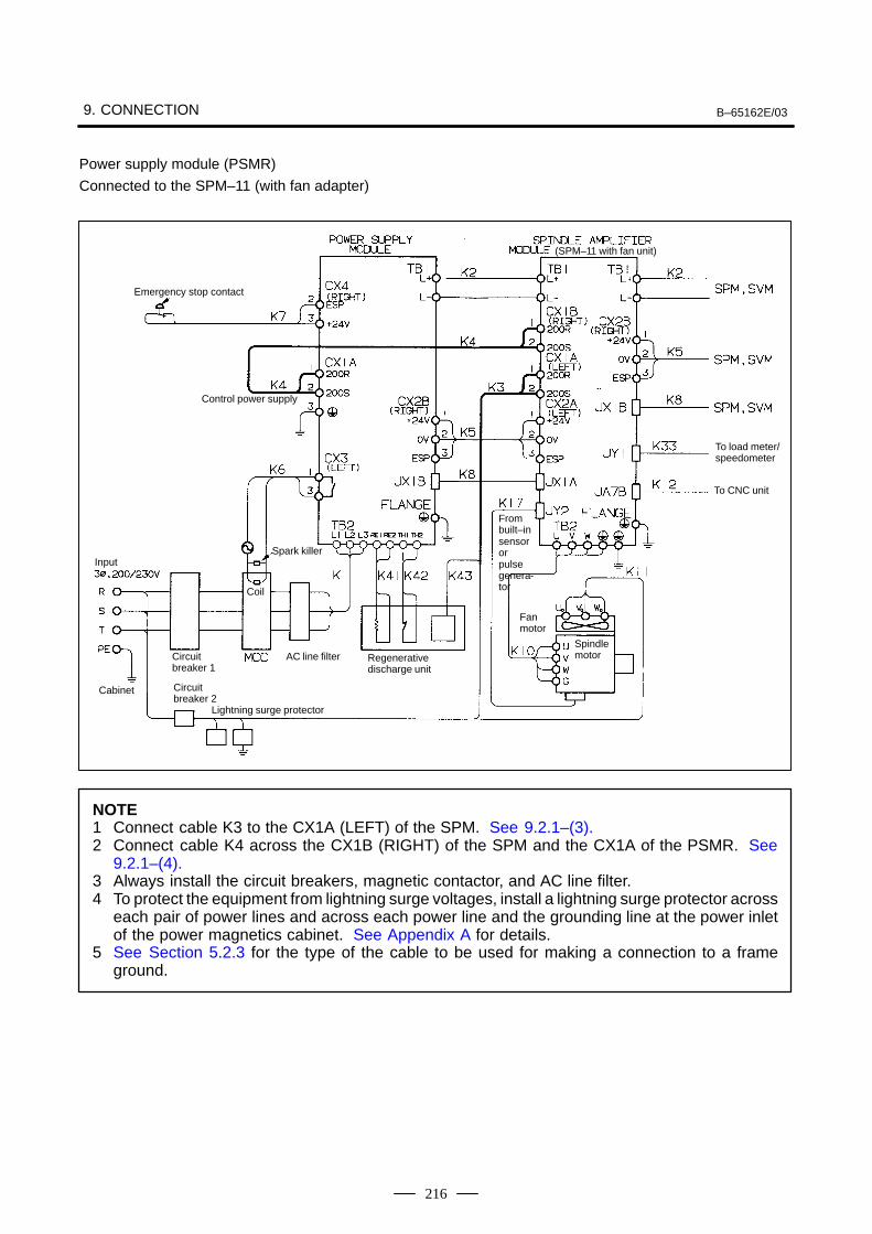
9. CONNECTION B–65162E/03
216
Power supply module (PSMR)
Connected to the SPM–11 (with fan adapter)
(SPM–11 with fan unit)
Emergency stop contact
Control power supply
To load meter/speedometer
To CNC unit
Frombuilt–insensororpulsegenera-tor
InputSpark killer
Coil
Fan motor
Circuitbreaker 1
AC line filter Regenerativedischarge unit
Spindlemotor
Cabinet Circuitbreaker 2
Lightning surge protector
NOTE1 Connect cable K3 to the CX1A (LEFT) of the SPM. See 9.2.1–(3).2 Connect cable K4 across the CX1B (RIGHT) of the SPM and the CX1A of the PSMR. See
9.2.1–(4).3 Always install the circuit breakers, magnetic contactor, and AC line filter.4 To protect the equipment from lightning surge voltages, install a lightning surge protector across
each pair of power lines and across each power line and the grounding line at the power inletof the power magnetics cabinet. See Appendix A for details.
5 See Section 5.2.3 for the type of the cable to be used for making a connection to a frameground.
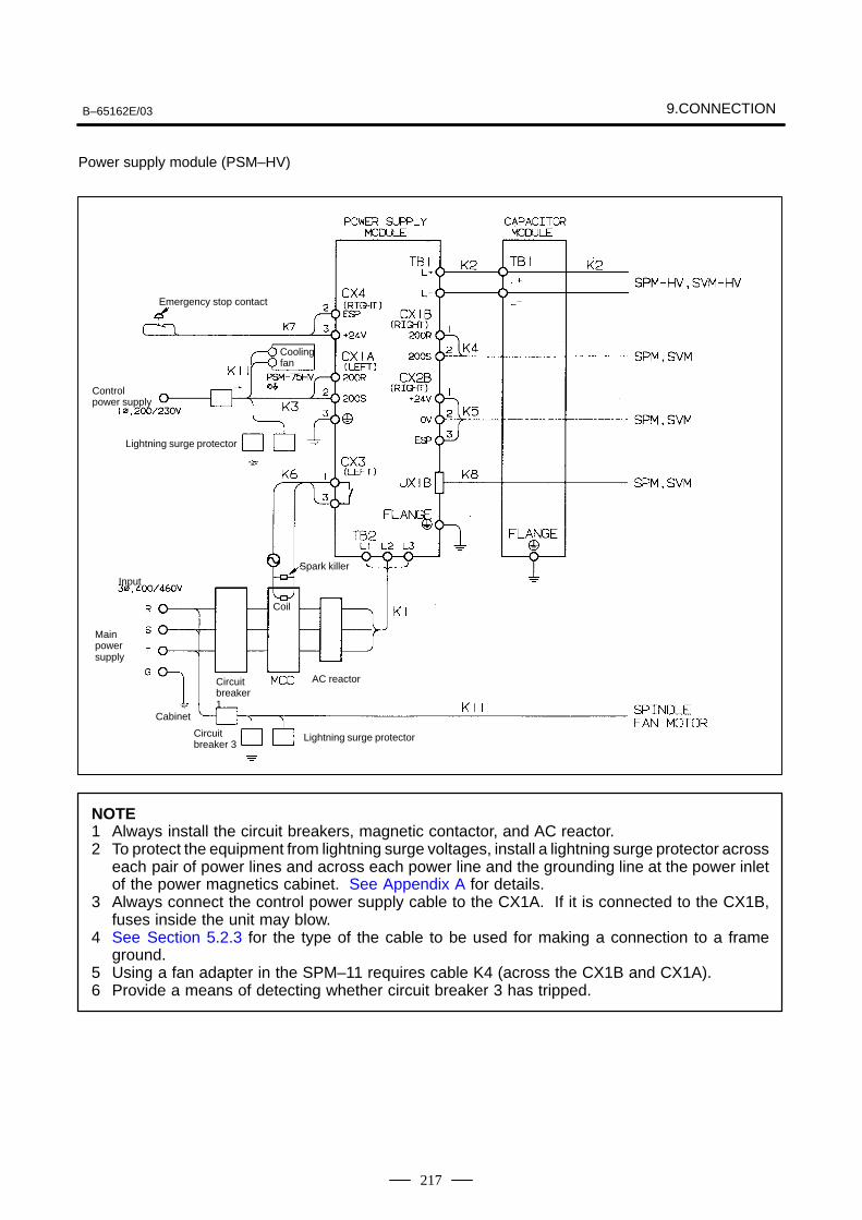
B–65162E/03 9.CONNECTION
217
Power supply module (PSM–HV)
Emergency stop contact
Coolingfan
Control power supply
Lightning surge protector
Spark killer
Input
Coil
Mainpowersupply
Circuitbreaker1
AC reactor
Circuitbreaker 3
Cabinet
Lightning surge protector
NOTE1 Always install the circuit breakers, magnetic contactor, and AC reactor.2 To protect the equipment from lightning surge voltages, install a lightning surge protector across
each pair of power lines and across each power line and the grounding line at the power inletof the power magnetics cabinet. See Appendix A for details.
3 Always connect the control power supply cable to the CX1A. If it is connected to the CX1B,fuses inside the unit may blow.
4 See Section 5.2.3 for the type of the cable to be used for making a connection to a frameground.
5 Using a fan adapter in the SPM–11 requires cable K4 (across the CX1B and CX1A).6 Provide a means of detecting whether circuit breaker 3 has tripped.

9. CONNECTION B–65162E/03
218
Power supply module (PSMV–HV)
Emergency stop contact
Control power supply
Circuit breaker 2
Lightning surge protector
For test by FANUC
Flange
Spark killer
Input
Coil
Main pow-er supply
AC reactor unit
Cabinet
Circuit breaker 3Lightning surge protector
NOTE1 Always install the magnetic contactor and AC reactor unit.2 To protect the equipment from lightning surge voltages, install a lightning surge protector across
each pair of power lines and across each power line and the grounding line at the power inletof the power magnetics cabinet. See Appendix A for details.
3 Always connect the control power supply cable to the CX1A. If it is connected to the CX1B,fuses inside the unit may blow.
4 See Section 5.2.3 for the type of the cable to be used for making a connection to a frameground.
5 The use of a fan adapter in the SPM–11 requires cable K4 (across the CX1B and CX1A).6 Provide a means of detecting whether circuit breaker 3 has tripped.
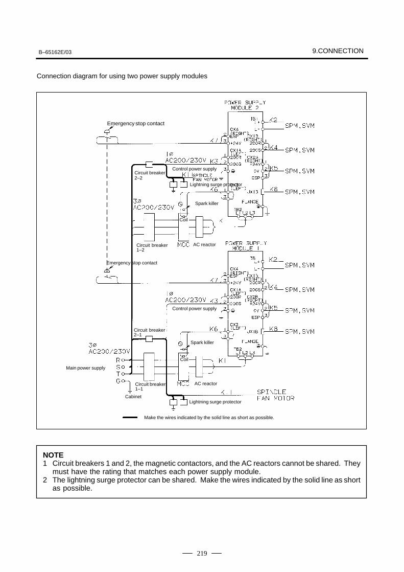
B–65162E/03 9.CONNECTION
219
Connection diagram for using two power supply modules
Emergency stop contact
Circuit breaker2–2
Emergency stop contact
Control power supply
Lightning surge protector
Spark killer
Coil
Spark killer
Lightning surge protector
Coil
Circuit breaker1–2
AC reactor
Circuit breaker2–1
Main power supply
Circuit breaker1–1
Cabinet
Make the wires indicated by the solid line as short as possible.
AC reactor
Control power supply
NOTE1 Circuit breakers 1 and 2, the magnetic contactors, and the AC reactors cannot be shared. They
must have the rating that matches each power supply module.2 The lightning surge protector can be shared. Make the wires indicated by the solid line as short
as possible.
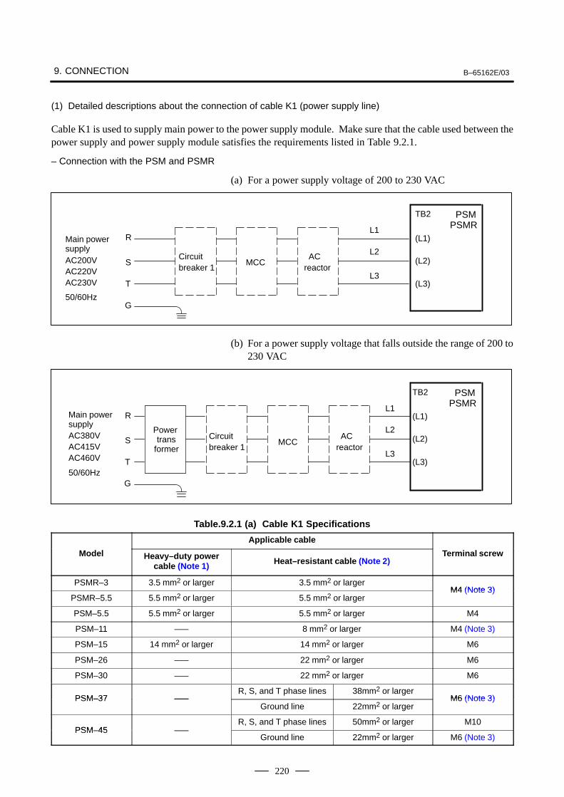
9. CONNECTION B–65162E/03
220
(1) Detailed descriptions about the connection of cable K1 (power supply line)
Cable K1 is used to supply main power to the power supply module. Make sure that the cable used between thepower supply and power supply module satisfies the requirements listed in Table 9.2.1.
– Connection with the PSM and PSMR
(a) For a power supply voltage of 200 to 230 VAC
R
S
T
G
L1
L2
L3
Main powersupplyAC200VAC220VAC230V
50/60Hz
Circuit breaker 1
MCC ACreactor
TB2
(L1)
(L2)
(L3)
PSMPSMR
(b) For a power supply voltage that falls outside the range of 200 to230 VAC
Main powersupplyAC380VAC415VAC460V
50/60Hz
R
S
T
G
Power trans
former
Circuit breaker 1
MCC ACreactor
TB2
(L1)
(L2)
(L3)
PSMPSMRL1
L2
L3
Table.9.2.1 (a) Cable K1 Specifications
Applicable cable
Model Heavy–duty powercable (Note 1) Heat–resistant cable (Note 2)
Terminal screw
PSMR–3 3.5 mm2 or larger 3.5 mm2 or largerM4 (Note 3)
PSMR–5.5 5.5 mm2 or larger 5.5 mm2 or largerM4 (Note 3)
PSM–5.5 5.5 mm2 or larger 5.5 mm2 or larger M4
PSM–11 ––– 8 mm2 or larger M4 (Note 3)
PSM–15 14 mm2 or larger 14 mm2 or larger M6
PSM–26 ––– 22 mm2 or larger M6
PSM–30 ––– 22 mm2 or larger M6
PSM–37 –––R, S, and T phase lines 38mm2 or larger
M6 (Note 3)PSM–37 –––Ground line 22mm2 or larger
M6 (Note 3)
PSM 45R, S, and T phase lines 50mm2 or larger M10
PSM–45 –––Ground line 22mm2 or larger M6 (Note 3)
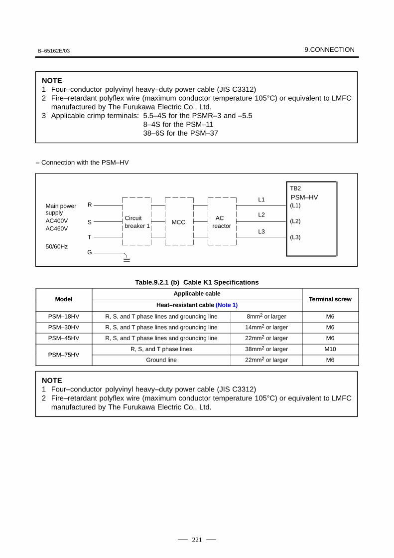
B–65162E/03 9.CONNECTION
221
NOTE1 Four–conductor polyvinyl heavy–duty power cable (JIS C3312)2 Fire–retardant polyflex wire (maximum conductor temperature 105°C) or equivalent to LMFC
manufactured by The Furukawa Electric Co., Ltd.3 Applicable crimp terminals: 5.5–4S for the PSMR–3 and –5.5
8–4S for the PSM–1138–6S for the PSM–37
– Connection with the PSM–HV
R
S
T
G
L1
L2
L3
Main powersupplyAC400VAC460V
50/60Hz
Circuit breaker 1
MCC ACreactor
TB2
(L1)
(L2)
(L3)
PSM–HV
Table.9.2.1 (b) Cable K1 Specifications
ModelApplicable cable
Terminal screwModelHeat–resistant cable (Note 1)
Terminal scre w
PSM–18HV R, S, and T phase lines and grounding line 8mm2 or larger M6
PSM–30HV R, S, and T phase lines and grounding line 14mm2 or larger M6
PSM–45HV R, S, and T phase lines and grounding line 22mm2 or larger M6
PSM 75HVR, S, and T phase lines 38mm2 or larger M10
PSM–75HVGround line 22mm2 or larger M6
NOTE1 Four–conductor polyvinyl heavy–duty power cable (JIS C3312)2 Fire–retardant polyflex wire (maximum conductor temperature 105°C) or equivalent to LMFC
manufactured by The Furukawa Electric Co., Ltd.
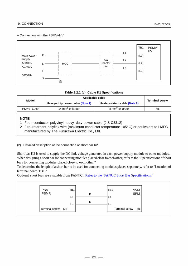
9. CONNECTION B–65162E/03
222
– Connection with the PSMV–HV
R
S
T
G
L1
L2
L3
Main powersupplyAC400VAC460V
50/60Hz
MCCAC
reactorunit
TB2
(L1)
(L2)
(L3)
PSMV–HV
Table.9.2.1 (c) Cable K1 Specifications
ModelApplicable cable
Terminal screwModelHeavy–duty power cable (Note 1) Heat–resistant cable (Note 2)
Terminal scre w
PSMV–11HV 14 mm2 or larger 8 mm2 or larger M6
NOTE1 Four–conductor polyvinyl heavy–duty power cable (JIS C3312)2 Fire–retardant polyflex wire (maximum conductor temperature 105C) or equivalent to LMFC
manufactured by The Furukawa Electric Co., Ltd.
(2) Detailed description of the connection of short bar K2
Short bar K2 is used to supply the DC link voltage generated in each power supply module to other modules.When designing a short bar for connecting modules placed close to each other, refer to the ”Specifications of shortbars for connecting modules placed close to each other.”To determine the length of a short bar to be used for connecting modules placed separately, refer to ”Location ofterminal board TB1.”Optional short bars are available from FANUC. Refer to the ”FANUC Short Bar Specifications.”
P
N
TB1
L+
L–
TB1
L+
L–
SVMSPM
PSMPSMR
Terminal screw M6 Terminal screw M6
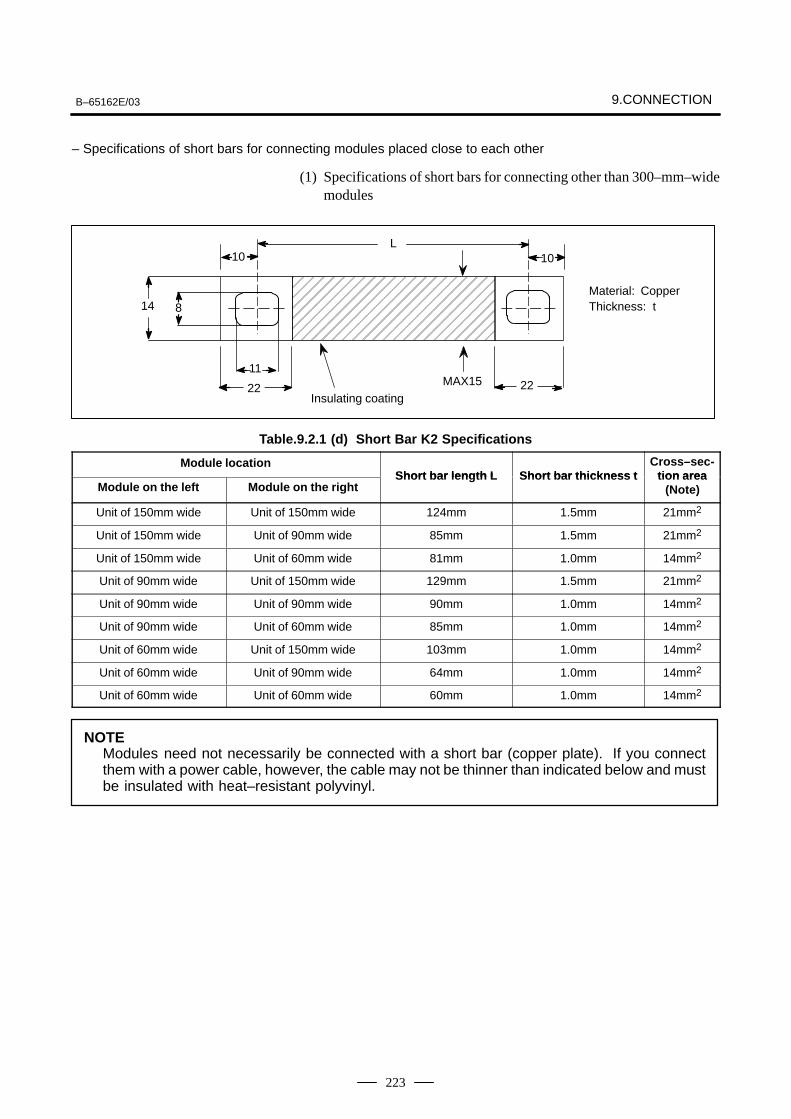
B–65162E/03 9.CONNECTION
223
– Specifications of short bars for connecting modules placed close to each other
(1) Specifications of short bars for connecting other than 300–mm–widemodules
ÇÇÇÇÇÇÇÇÇÇÇÇÇÇÇÇÇÇÇÇÇÇÇÇÇÇÇÇÇÇÇÇÇÇÇÇÇÇÇÇÇÇÇÇ
Material: CopperThickness: t
Insulating coating
L1010
22
14 8
22
11MAX15
Table.9.2.1 (d) Short Bar K2 Specifications
Module locationShort bar length L Short bar thickness t
Cross–sec-tion area
Module on the left Module on the rightShort bar length L Short bar thickness t tion area
(Note)
Unit of 150mm wide Unit of 150mm wide 124mm 1.5mm 21mm2
Unit of 150mm wide Unit of 90mm wide 85mm 1.5mm 21mm2
Unit of 150mm wide Unit of 60mm wide 81mm 1.0mm 14mm2
Unit of 90mm wide Unit of 150mm wide 129mm 1.5mm 21mm2
Unit of 90mm wide Unit of 90mm wide 90mm 1.0mm 14mm2
Unit of 90mm wide Unit of 60mm wide 85mm 1.0mm 14mm2
Unit of 60mm wide Unit of 150mm wide 103mm 1.0mm 14mm2
Unit of 60mm wide Unit of 90mm wide 64mm 1.0mm 14mm2
Unit of 60mm wide Unit of 60mm wide 60mm 1.0mm 14mm2
NOTEModules need not necessarily be connected with a short bar (copper plate). If you connectthem with a power cable, however, the cable may not be thinner than indicated below and mustbe insulated with heat–resistant polyvinyl.
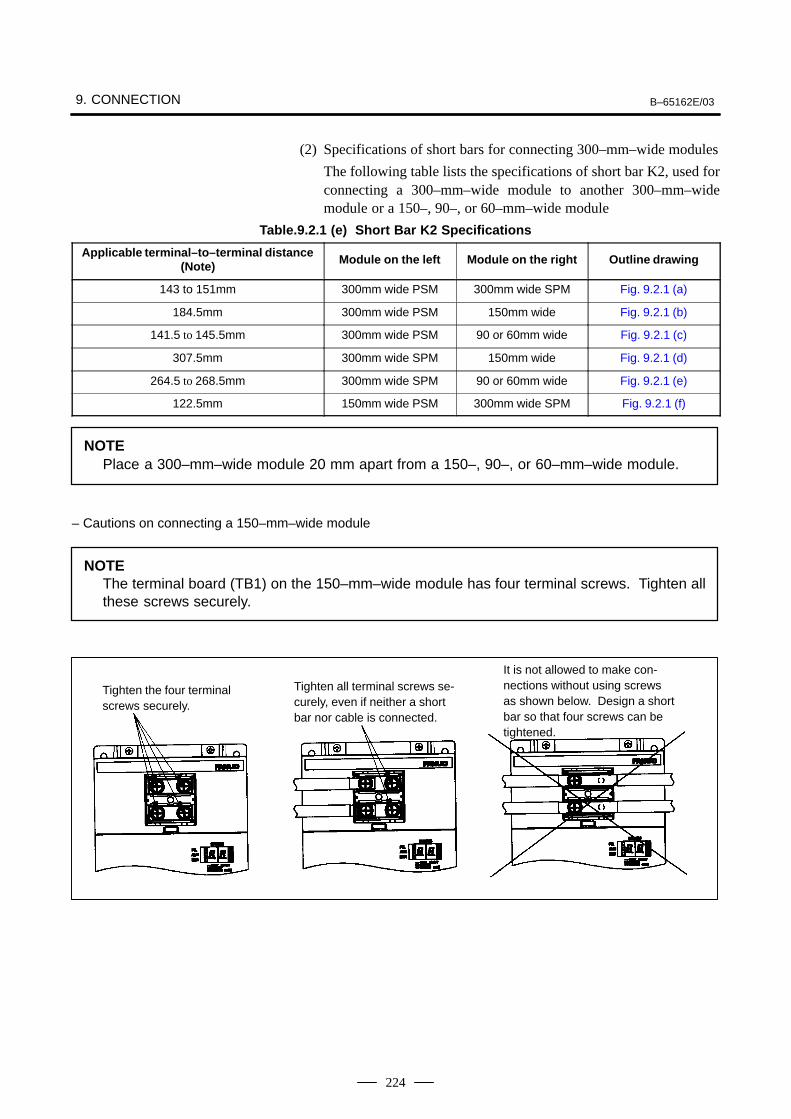
9. CONNECTION B–65162E/03
224
(2) Specifications of short bars for connecting 300–mm–wide modules
The following table lists the specifications of short bar K2, used forconnecting a 300–mm–wide module to another 300–mm–widemodule or a 150–, 90–, or 60–mm–wide module
Table.9.2.1 (e) Short Bar K2 Specifications
Applicable terminal–to–terminal distance(Note) Module on the left Module on the right Outline drawing
143 to 151mm 300mm wide PSM 300mm wide SPM Fig. 9.2.1 (a)
184.5mm 300mm wide PSM 150mm wide Fig. 9.2.1 (b)
141.5 to 145.5mm 300mm wide PSM 90 or 60mm wide Fig. 9.2.1 (c)
307.5mm 300mm wide SPM 150mm wide Fig. 9.2.1 (d)
264.5 to 268.5mm 300mm wide SPM 90 or 60mm wide Fig. 9.2.1 (e)
122.5mm 150mm wide PSM 300mm wide SPM Fig. 9.2.1 (f)
NOTEPlace a 300–mm–wide module 20 mm apart from a 150–, 90–, or 60–mm–wide module.
– Cautions on connecting a 150–mm–wide module
NOTEThe terminal board (TB1) on the 150–mm–wide module has four terminal screws. Tighten allthese screws securely.
Tighten the four terminalscrews securely.
Tighten all terminal screws se-curely, even if neither a shortbar nor cable is connected.
It is not allowed to make con-nections without using screwsas shown below. Design a shortbar so that four screws can betightened.
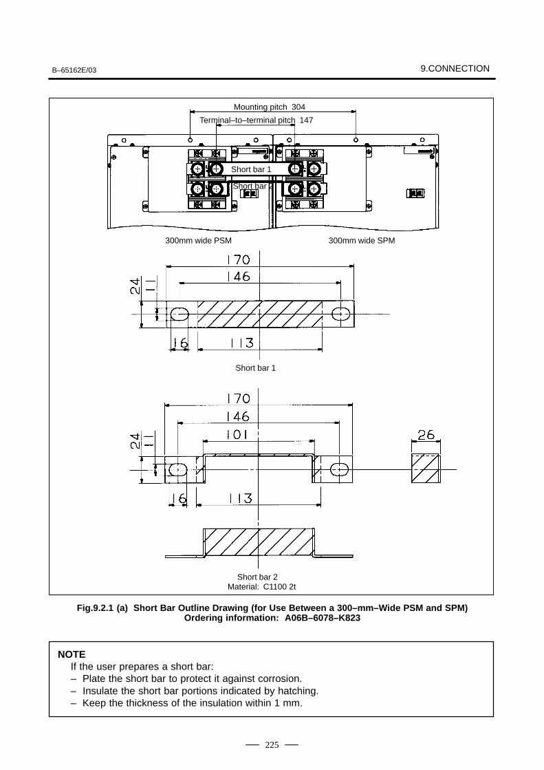
B–65162E/03 9.CONNECTION
225
Mounting pitch 304
Terminal–to–terminal pitch 147
Short bar 1
Short bar 2
300mm wide PSM 300mm wide SPM
Material: C1100 2t
Short bar 1
Short bar 2
Fig.9.2.1 (a) Short Bar Outline Drawing (for Use Between a 300–mm–Wide PSM and SPM)Ordering information: A06B–6078–K823
NOTEIf the user prepares a short bar:– Plate the short bar to protect it against corrosion.– Insulate the short bar portions indicated by hatching.– Keep the thickness of the insulation within 1 mm.
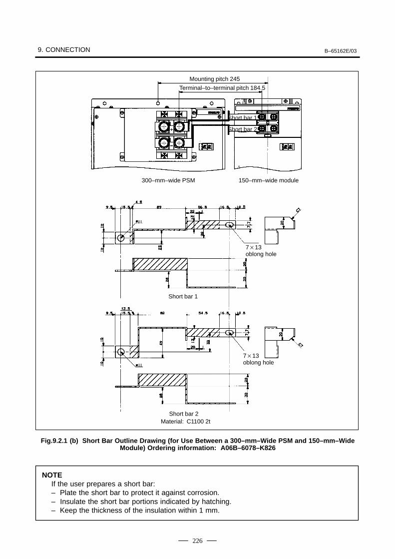
9. CONNECTION B–65162E/03
226
Mounting pitch 245
Terminal–to–terminal pitch 184.5
Short bar 1
Short bar 2
300–mm–wide PSM 150–mm–wide module
713 oblong hole
Material: C1100 2t
713 oblong hole
Short bar 1
Short bar 2
Fig.9.2.1 (b) Short Bar Outline Drawing (for Use Between a 300–mm–Wide PSM and 150–mm–WideModule) Ordering information: A06B–6078–K826
NOTEIf the user prepares a short bar:– Plate the short bar to protect it against corrosion.– Insulate the short bar portions indicated by hatching.– Keep the thickness of the insulation within 1 mm.
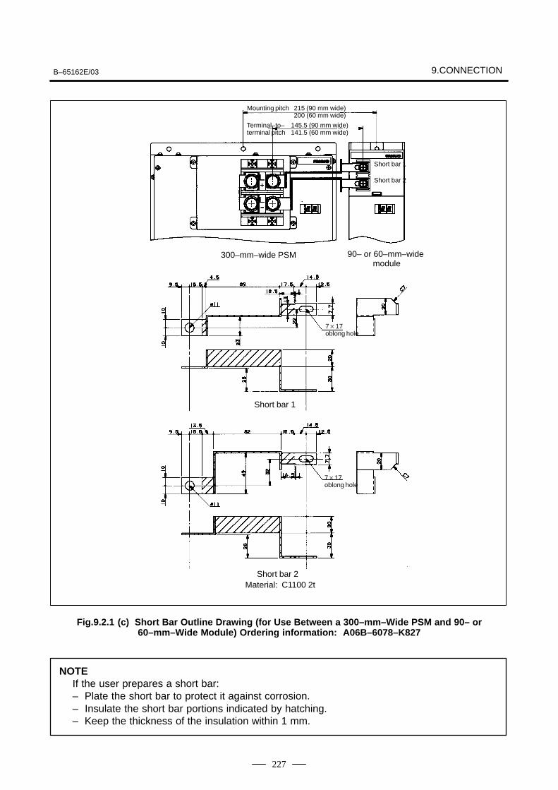
B–65162E/03 9.CONNECTION
227
215 (90 mm wide)200 (60 mm wide)
Terminal–to–terminal pitch
145.5 (90 mm wide)141.5 (60 mm wide)
Mounting pitch
Short bar 1
Short bar 2
717 oblong hole
Material: C1100 2t
717 oblong hole
Short bar 1
Short bar 2
300–mm–wide PSM 90– or 60–mm–wide module
Fig.9.2.1 (c) Short Bar Outline Drawing (for Use Between a 300–mm–Wide PSM and 90– or60–mm–Wide Module) Ordering information: A06B–6078–K827
NOTEIf the user prepares a short bar:– Plate the short bar to protect it against corrosion.– Insulate the short bar portions indicated by hatching.– Keep the thickness of the insulation within 1 mm.
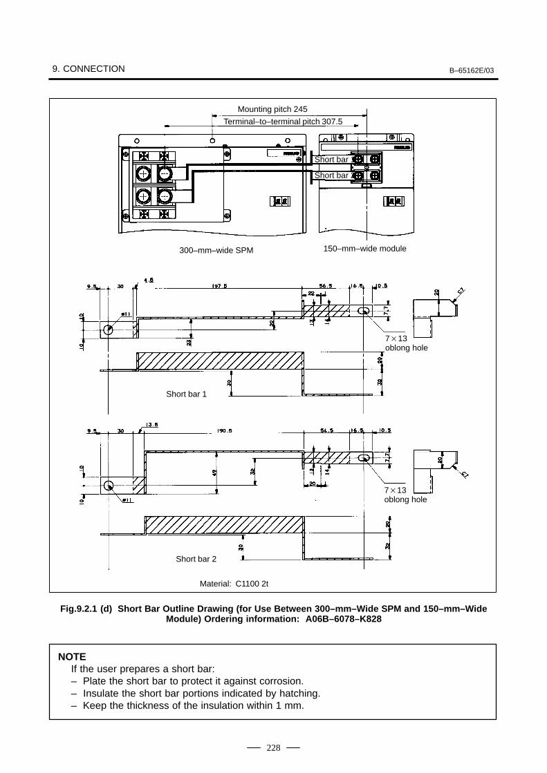
9. CONNECTION B–65162E/03
228
Mounting pitch 245
Terminal–to–terminal pitch 307.5
Short bar 1
Short bar 2
300–mm–wide SPM 150–mm–wide module
713 oblong hole
Material: C1100 2t
713 oblong hole
Short bar 1
Short bar 2
Fig.9.2.1 (d) Short Bar Outline Drawing (for Use Between 300–mm–Wide SPM and 150–mm–WideModule) Ordering information: A06B–6078–K828
NOTEIf the user prepares a short bar:– Plate the short bar to protect it against corrosion.– Insulate the short bar portions indicated by hatching.– Keep the thickness of the insulation within 1 mm.
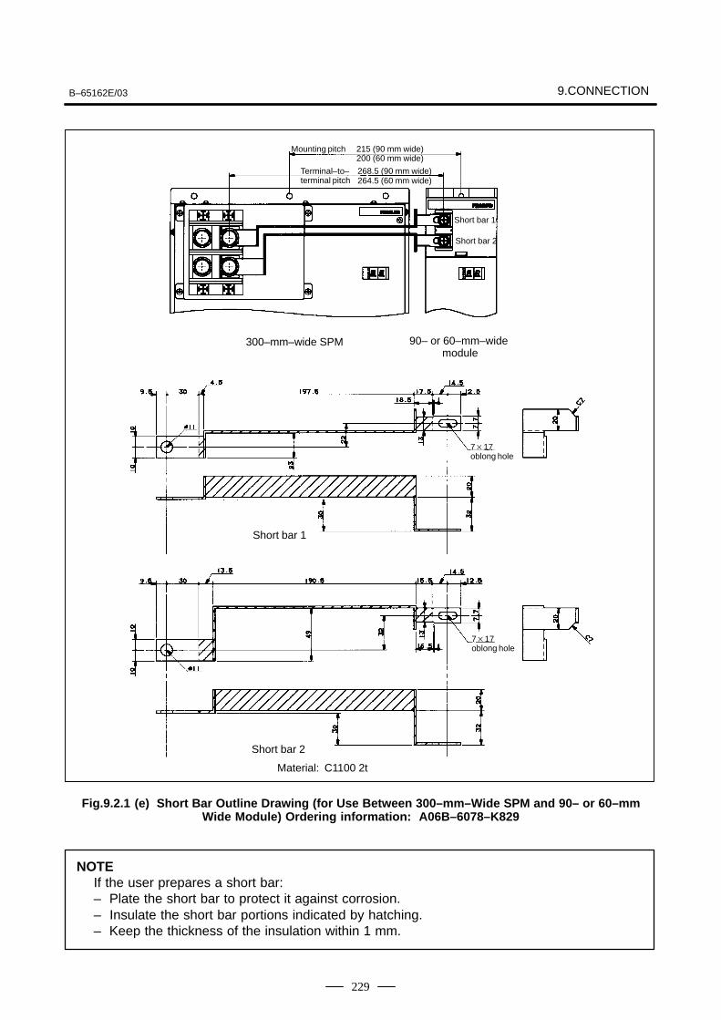
B–65162E/03 9.CONNECTION
229
Mounting pitch
Short bar 1
Short bar 2
717 oblong hole
Material: C1100 2t
717 oblong hole
Short bar 1
Short bar 2
215 (90 mm wide)200 (60 mm wide)
Terminal–to–terminal pitch
268.5 (90 mm wide)264.5 (60 mm wide)
300–mm–wide SPM 90– or 60–mm–wide module
Fig.9.2.1 (e) Short Bar Outline Drawing (for Use Between 300–mm–Wide SPM and 90– or 60–mmWide Module) Ordering information: A06B–6078–K829
NOTEIf the user prepares a short bar:– Plate the short bar to protect it against corrosion.– Insulate the short bar portions indicated by hatching.– Keep the thickness of the insulation within 1 mm.
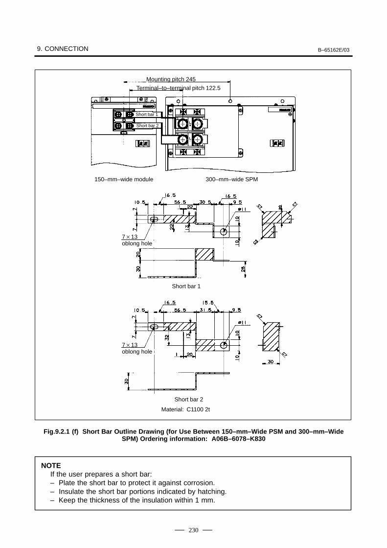
9. CONNECTION B–65162E/03
230
Mounting pitch 245
Terminal–to–terminal pitch 122.5
Short bar 1
Short bar 2
300–mm–wide SPM150–mm–wide module
713 oblong hole
Material: C1100 2t
713 oblong hole
Short bar 1
Short bar 2
Fig.9.2.1 (f) Short Bar Outline Drawing (for Use Between 150–mm–Wide PSM and 300–mm–WideSPM) Ordering information: A06B–6078–K830
NOTEIf the user prepares a short bar:– Plate the short bar to protect it against corrosion.– Insulate the short bar portions indicated by hatching.– Keep the thickness of the insulation within 1 mm.
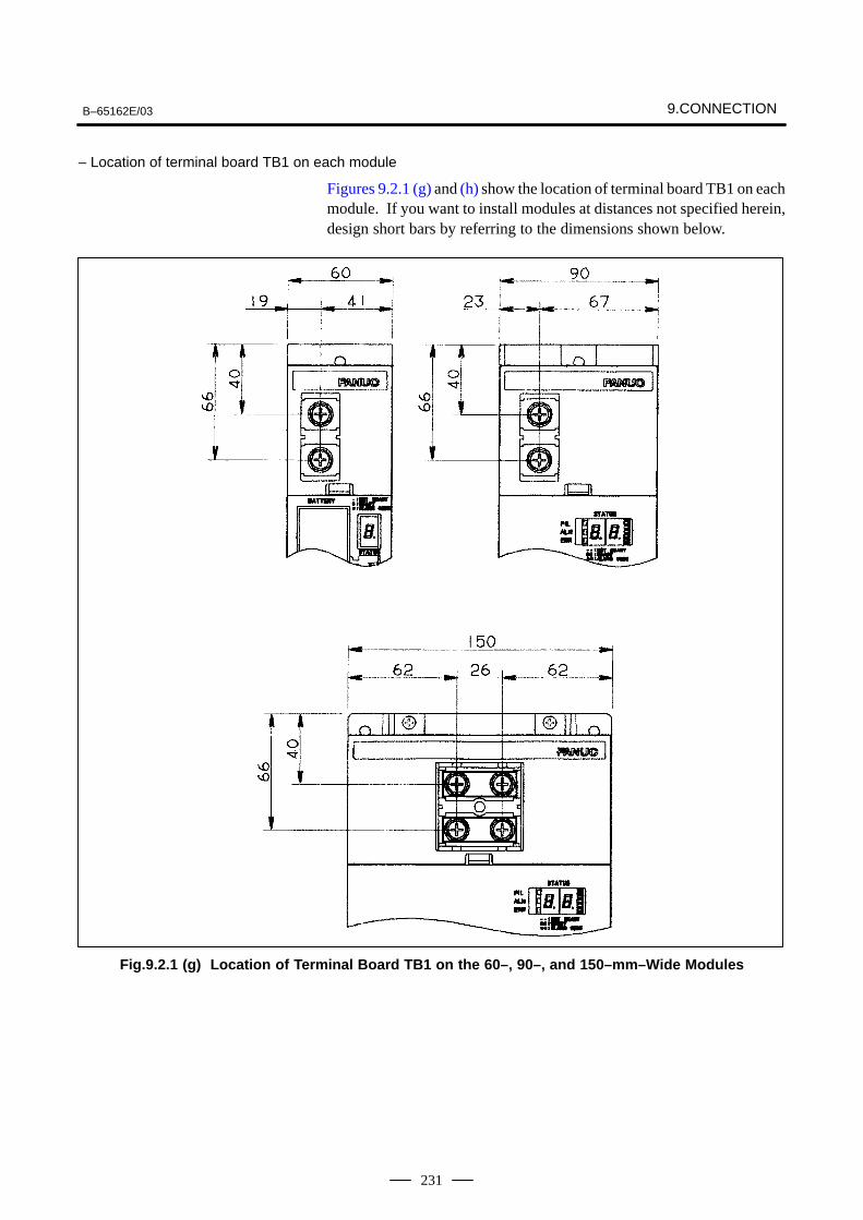
B–65162E/03 9.CONNECTION
231
– Location of terminal board TB1 on each module
Figures 9.2.1 (g) and (h) show the location of terminal board TB1 on eachmodule. If you want to install modules at distances not specified herein,design short bars by referring to the dimensions shown below.
Fig.9.2.1 (g) Location of Terminal Board TB1 on the 60–, 90–, and 150–mm–Wide Modules
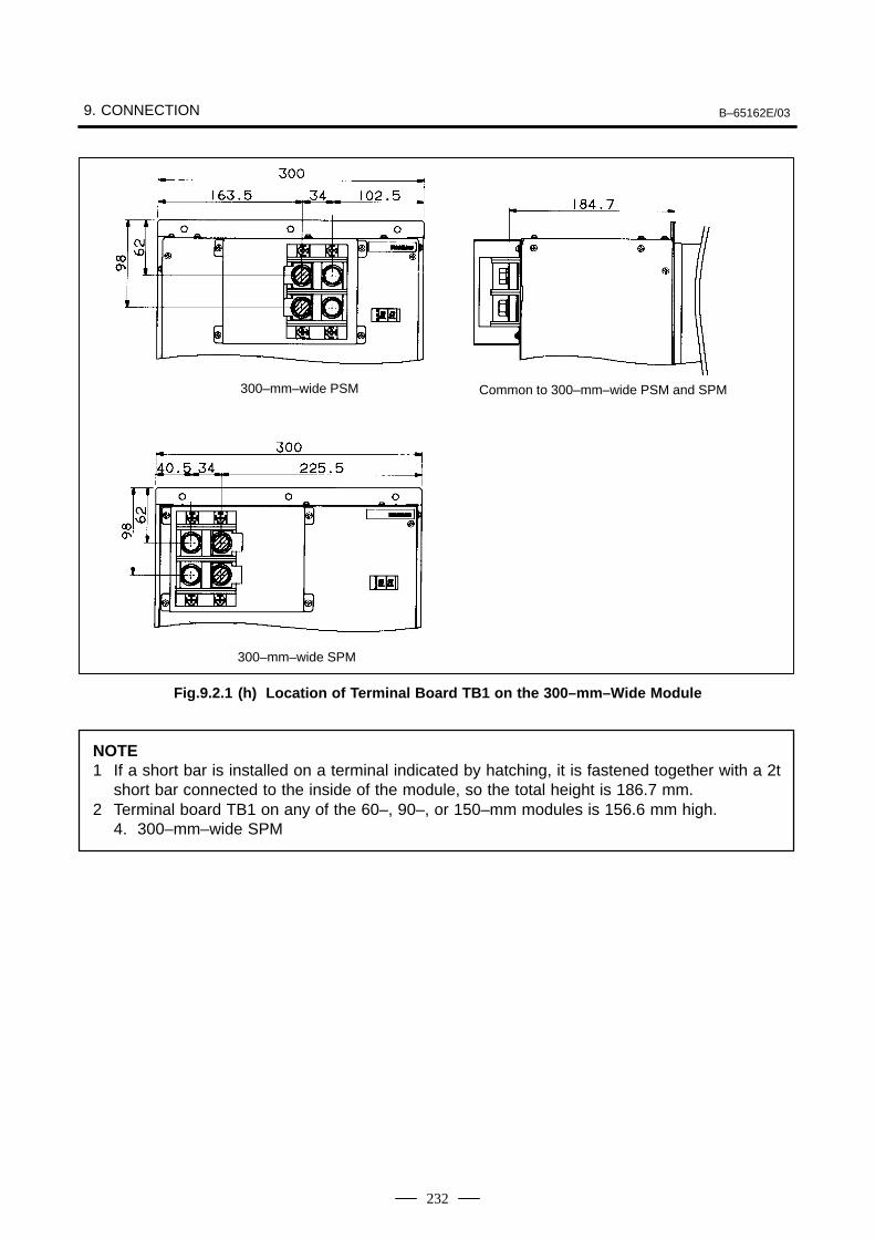
9. CONNECTION B–65162E/03
232
Common to 300–mm–wide PSM and SPM300–mm–wide PSM
300–mm–wide SPM
Fig.9.2.1 (h) Location of Terminal Board TB1 on the 300–mm–Wide Module
NOTE1 If a short bar is installed on a terminal indicated by hatching, it is fastened together with a 2t
short bar connected to the inside of the module, so the total height is 186.7 mm.2 Terminal board TB1 on any of the 60–, 90–, or 150–mm modules is 156.6 mm high.
4. 300–mm–wide SPM
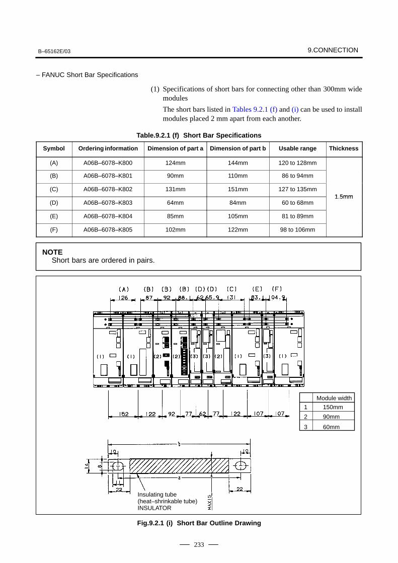
B–65162E/03 9.CONNECTION
233
– FANUC Short Bar Specifications
(1) Specifications of short bars for connecting other than 300mm widemodules
The short bars listed in Tables 9.2.1 (f) and (i) can be used to installmodules placed 2 mm apart from each another.
Table.9.2.1 (f) Short Bar Specifications
Symbol Ordering information Dimension of part a Dimension of part b Usable range Thickness
(A) A06B–6078–K800 124mm 144mm 120 to 128mm
(B) A06B–6078–K801 90mm 110mm 86 to 94mm
(C) A06B–6078–K802 131mm 151mm 127 to 135mm1 5mm
(D) A06B–6078–K803 64mm 84mm 60 to 68mm1.5mm
(E) A06B–6078–K804 85mm 105mm 81 to 89mm
(F) A06B–6078–K805 102mm 122mm 98 to 106mm
NOTEShort bars are ordered in pairs.
Module width
Insulating tube (heat–shrinkable tube)INSULATOR
1 150mm
2 90mm
3 60mm
Fig.9.2.1 (i) Short Bar Outline Drawing
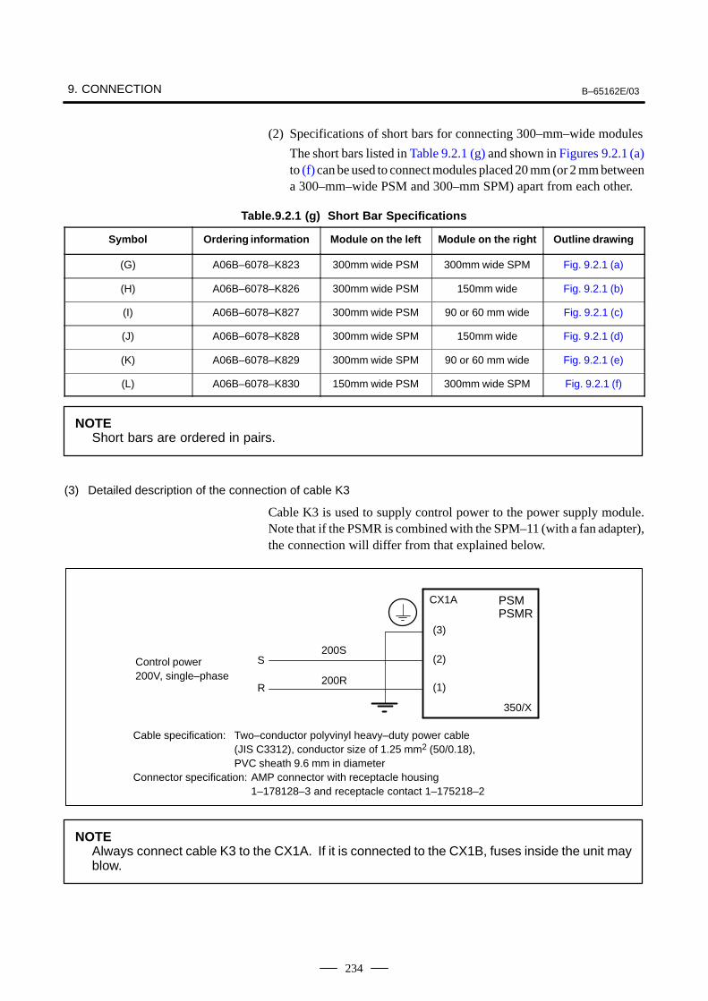
9. CONNECTION B–65162E/03
234
(2) Specifications of short bars for connecting 300–mm–wide modules
The short bars listed in Table 9.2.1 (g) and shown in Figures 9.2.1 (a)to (f) can be used to connect modules placed 20 mm (or 2 mm betweena 300–mm–wide PSM and 300–mm SPM) apart from each other.
Table.9.2.1 (g) Short Bar Specifications
Symbol Ordering information Module on the left Module on the right Outline drawing
(G) A06B–6078–K823 300mm wide PSM 300mm wide SPM Fig. 9.2.1 (a)
(H) A06B–6078–K826 300mm wide PSM 150mm wide Fig. 9.2.1 (b)
(I) A06B–6078–K827 300mm wide PSM 90 or 60 mm wide Fig. 9.2.1 (c)
(J) A06B–6078–K828 300mm wide SPM 150mm wide Fig. 9.2.1 (d)
(K) A06B–6078–K829 300mm wide SPM 90 or 60 mm wide Fig. 9.2.1 (e)
(L) A06B–6078–K830 150mm wide PSM 300mm wide SPM Fig. 9.2.1 (f)
NOTEShort bars are ordered in pairs.
(3) Detailed description of the connection of cable K3
Cable K3 is used to supply control power to the power supply module.Note that if the PSMR is combined with the SPM–11 (with a fan adapter),the connection will differ from that explained below.
Control power 200V, single–phase
S
R
200S
200R
CX1A PSMPSMR
(3)
(2)
(1)
350/X
Cable specification: Two–conductor polyvinyl heavy–duty power cable (JIS C3312), conductor size of 1.25 mm2 (50/0.18), PVC sheath 9.6 mm in diameter
Connector specification: AMP connector with receptacle housing 1–178128–3 and receptacle contact 1–175218–2
NOTEAlways connect cable K3 to the CX1A. If it is connected to the CX1B, fuses inside the unit mayblow.

B–65162E/03 9.CONNECTION
235
– Cable K3 for combining the PSMR and the SPM–11 (with a fan adapter)
200S
200R
CX1A
(3)
(2)
(1)
SPM–11
350/X
Cable specification: Two–conductor polyvinyl heavy–duty power cable (JIS C3312), conductor size of 1.25 mm2 (50/0.18), PVC sheath 9.6 mm in diameter
Connector specification: AMP connector with receptacle housing 1–178128–3 and receptacle contact 1–175218–2
Control power 200 VAC, 50/60 Hz single–phase
S
R
NOTEIf the PSMR is combined with the SPM–11 (with a fan adapter), the position at which cable K3 isconnected differs from other combinations. See the connection diagram under ”Power supplymodule (PSMR); connected with the SPM–11 (with a fan adapter)” in Section 9.2.1 for details.
(4) Detailed description of the connection of cable K4
Cable K4 is used to supply power to the cooling fan of a module. Use thiscable to connect the power supply module to a spindle amplifier moduleor servo amplifier module having a built–in cooling fan (see below).
Modules to be connected using cable K4SPM–11 (required only when TYPE 3 or a fan adapter is used)SPM–15 to SPM–30SPM–11HV (required only when a fan adapter is used)SPM–15HV to SPM–45HVSVM1–240 and SVM1–360
200S
200R
PSM CX1B
(3)
(2)
(1)
350/X
CX1A
(3)
(2)
(1)
SPM
350/X
Cable specification: Two–conductor polyvinyl heavy–duty power cable (JIS C3312), conductor size of 1.25 mm2 (50/0.18), PVC sheath 9.6 mm in diameter
Connector specification: AMP connector with receptacle housing 1–178128–3 and receptacle contact 1–175218–2
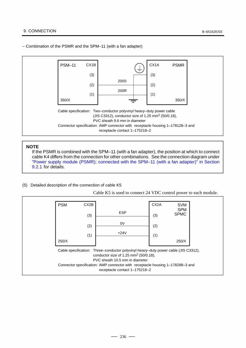
9. CONNECTION B–65162E/03
236
– Combination of the PSMR and the SPM–11 (with a fan adapter)
200S
200R
PSM–11 CX1B
(3)
(2)
(1)
350/X
CX1A
(3)
(2)
(1)
PSMR
350/X
Cable specification: Two–conductor polyvinyl heavy–duty power cable (JIS C3312), conductor size of 1.25 mm2 (50/0.18), PVC sheath 9.6 mm in diameter
Connector specification: AMP connector with receptacle housing 1–178128–3 and receptacle contact 1–175218–2
NOTEIf the PSMR is combined with the SPM–11 (with a fan adapter), the position at which to connectcable K4 differs from the connection for other combinations. See the connection diagram under”Power supply module (PSMR); connected with the SPM–11 (with a fan adapter)” in Section9.2.1 for details.
(5) Detailed description of the connection of cable K5
Cable K5 is used to connect 24 VDC control power to each module.
ESP
0V
+24V
PSM CX2B
(3)
(2)
(1)
CX2A
(3)
(2)
(1)
SVMSPM
250/X250/X
Cable specification: Three–conductor polyvinyl heavy–duty power cable (JIS C3312), conductor size of 1.25 mm2 (50/0.18), PVC sheath 10.5 mm in diameter
Connector specification: AMP connector with receptacle housing 1–178288–3 and receptacle contact 1–175218–2
SPMC
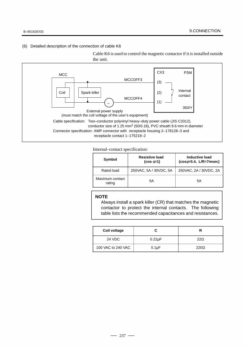
B–65162E/03 9.CONNECTION
237
(6) Detailed description of the connection of cable K6
Cable K6 is used to control the magnetic contactor if it is installed outsidethe unit.
MCC
Coil Spark killer
MCCOFF3
MCCOFF4~
CX3
(3)
(2)
(1)
PSM
350/Y
Internalcontact
External power supply(must match the coil voltage of the user’s equipment)
Cable specification: Two–conductor polyvinyl heavy–duty power cable (JIS C3312), conductor size of 1.25 mm2 (50/0.18), PVC sheath 9.6 mm in diameter
Connector specification: AMP connector with receptacle housing 2–178128–3 and receptacle contact 1–175218–2
Internal–contact specification:
Symbol Resistive load (cos φ=1)
Inductive load(cos φ=0.4, L/R=7msec)
Rated load 250VAC, 5A / 30VDC, 5A 250VAC, 2A / 30VDC, 2A
Maximum contactrating 5A 5A
NOTEAlways install a spark killer (CR) that matches the magneticcontactor to protect the internal contacts. The followingtable lists the recommended capacitances and resistances.
Coil voltage C R
24 VDC 0.22µF 22Ω
100 VAC to 240 VAC 0.1µF 220Ω
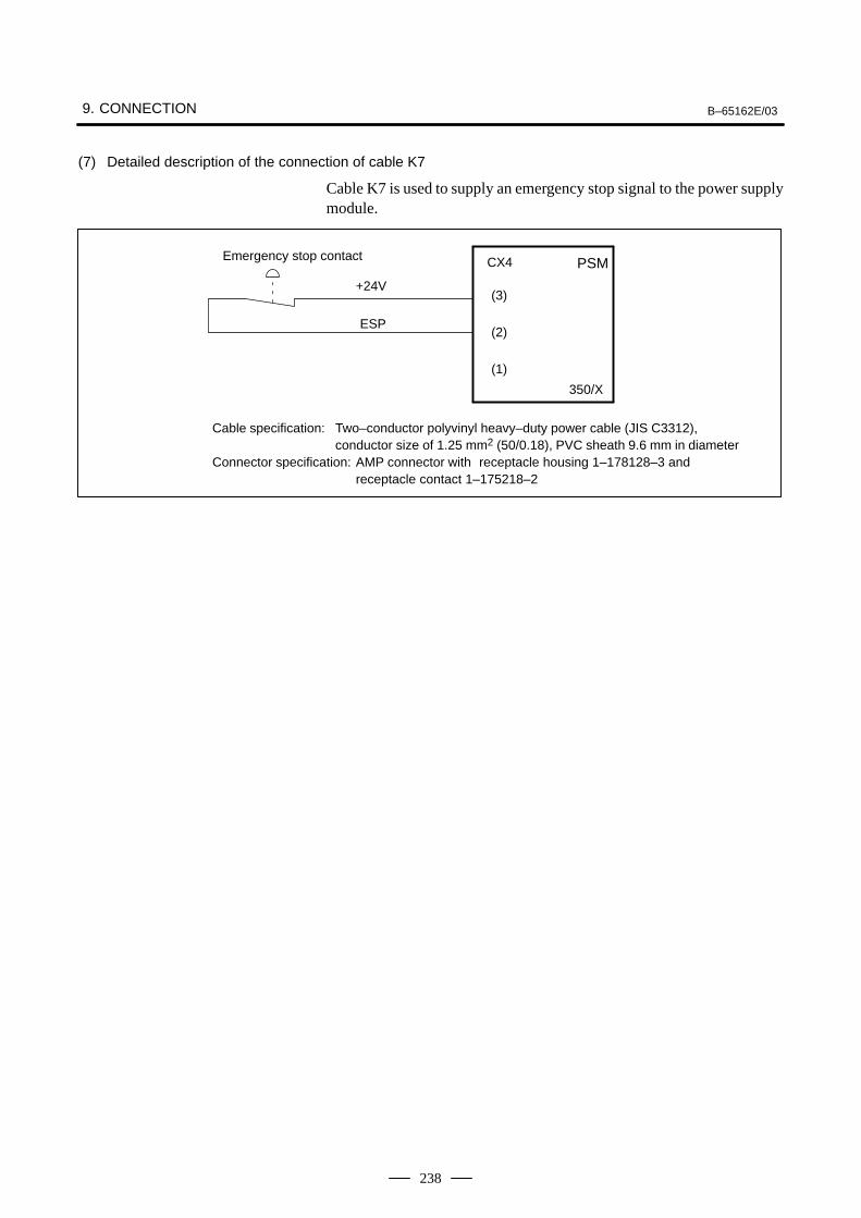
9. CONNECTION B–65162E/03
238
(7) Detailed description of the connection of cable K7
Cable K7 is used to supply an emergency stop signal to the power supplymodule.
+24V
ESP
CX4
(3)
(2)
(1)
PSM
350/X
Cable specification: Two–conductor polyvinyl heavy–duty power cable (JIS C3312), conductor size of 1.25 mm2 (50/0.18), PVC sheath 9.6 mm in diameter
Connector specification: AMP connector with receptacle housing 1–178128–3 and receptacle contact 1–175218–2
Emergency stop contact
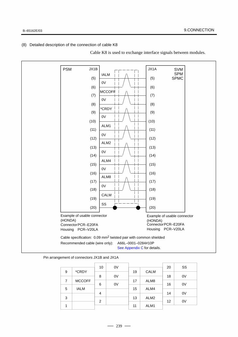
B–65162E/03 9.CONNECTION
239
(8) Detailed description of the connection of cable K8
Cable K8 is used to exchange interface signals between modules.
PSM JX1B JX1A SVM SPMSPMC(5)
(6)
(7)
(8)
(9)
(10)
(11)
(12)
(13)
(14)
(15)
(16)
(17)
(18)
(19)
(20)
(5)
(6)
(7)
(8)
(9)
(10)
(11)
(12)
(13)
(14)
(15)
(16)
(17)
(18)
(19)
(20)
IALM
0V
MCCOFF
0V
*CRDY
ALM1
0V
ALM4
0V
ALM8
0V
CALM
SS
0V
ALM2
0V
Example of usable connector(HONDA)ConnectorPCR–E20FAHousing PCR–V20LA
ConnectorPCR–E20FAHousing PCR–V20LA
Cable specification: 0.09 mm2 twisted pair with common shielded
Recommended cable (wire only): A66L–0001–0284#10PSee Appendix C for details.
Pin arrangement of connectors JX1B and JX1A
IALM
MCCOFF
*CRDY9
7
5
1
3
10
8
6
2
4
19
17
15
11
13
0V
0V
0V
CALM
ALM8
ALM4
ALM2
ALM1
20
18
16
12
14
SS
0V
0V
0V
0V
Example of usable connector(HONDA)
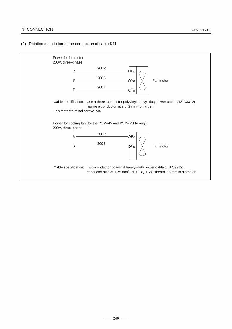
9. CONNECTION B–65162E/03
240
(9) Detailed description of the connection of cable K11
R
S
T
200R
200S
200T
R0
S0
T0
Fan motor
Power for fan motor200V, three–phase
Cable specification: Use a three–conductor polyvinyl heavy–duty power cable (JIS C3312) having a conductor size of 2 mm2 or larger.
Fan motor terminal screw: M4
R
S
200R
200S
R0
S0 Fan motor
Power for cooling fan (for the PSM–45 and PSM–75HV only)200V, three–phase
Cable specification: Two–conductor polyvinyl heavy–duty power cable (JIS C3312), conductor size of 1.25 mm2 (50/0.18), PVC sheath 9.6 mm in diameter
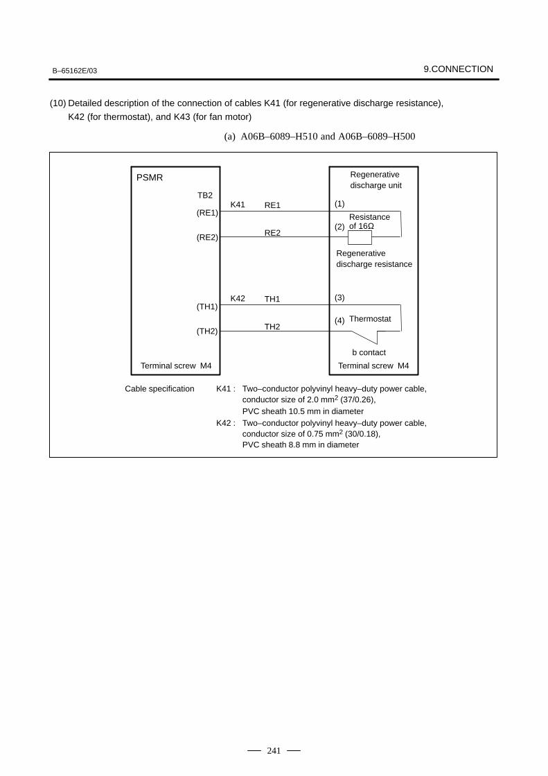
B–65162E/03 9.CONNECTION
241
(10) Detailed description of the connection of cables K41 (for regenerative discharge resistance),
K42 (for thermostat), and K43 (for fan motor)
(a) A06B–6089–H510 and A06B–6089–H500
RE1
RE2
PSMR
TB2
(RE1)
(RE2)
Regenerative discharge unit
(1)
(2)Resistance of 16Ω
Regenerative discharge resistance
K41
TH1
TH2
(TH1)
(TH2)
(3)
(4) Thermostat
K42
b contact
Terminal screw M4 Terminal screw M4
Cable specification K41 : Two–conductor polyvinyl heavy–duty power cable, conductor size of 2.0 mm2 (37/0.26), PVC sheath 10.5 mm in diameter
K42 : Two–conductor polyvinyl heavy–duty power cable, conductor size of 0.75 mm2 (30/0.18), PVC sheath 8.8 mm in diameter
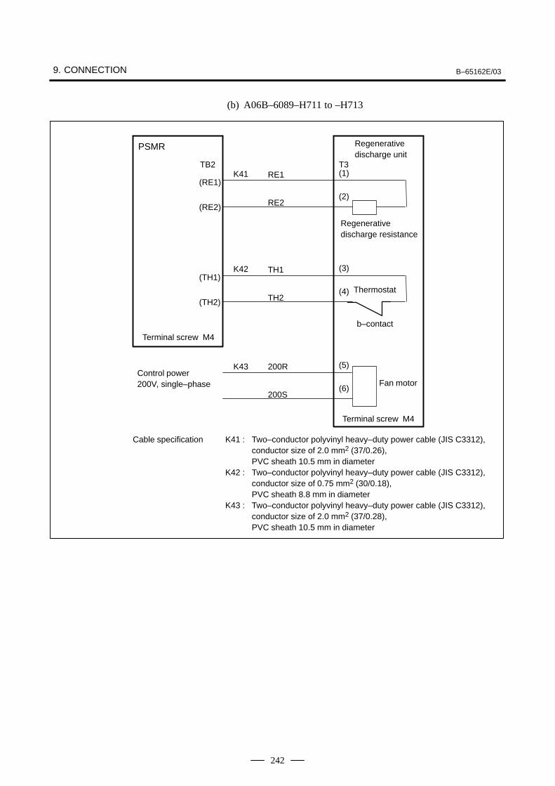
9. CONNECTION B–65162E/03
242
(b) A06B–6089–H711 to –H713
RE1
RE2
PSMR
TB2
(RE1)
(RE2)
Regenerative discharge unit
(1)
(2)
Regenerative discharge resistance
K41
TH1
TH2
(TH1)
(TH2)
(3)
(4) Thermostat
K42
b–contact
Terminal screw M4
Terminal screw M4
Cable specification K41 : Two–conductor polyvinyl heavy–duty power cable (JIS C3312), conductor size of 2.0 mm2 (37/0.26), PVC sheath 10.5 mm in diameter
K42 : Two–conductor polyvinyl heavy–duty power cable (JIS C3312), conductor size of 0.75 mm2 (30/0.18), PVC sheath 8.8 mm in diameter
K43 : Two–conductor polyvinyl heavy–duty power cable (JIS C3312), conductor size of 2.0 mm2 (37/0.28), PVC sheath 10.5 mm in diameter
T3
200R
200S
(5)
(6)
K43
Fan motorControl power200V, single–phase
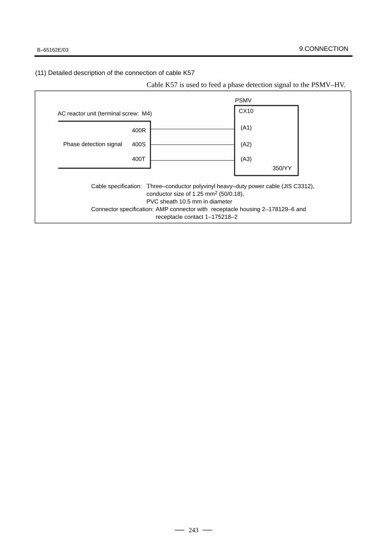
B–65162E/03 9.CONNECTION
243
(11) Detailed description of the connection of cable K57
Cable K57 is used to feed a phase detection signal to the PSMV–HV.
400R
400S
400T
CX10
(A1)
(A2)
(A3)
350/YY
Cable specification: Three–conductor polyvinyl heavy–duty power cable (JIS C3312), conductor size of 1.25 mm2 (50/0.18), PVC sheath 10.5 mm in diameter
Connector specification: AMP connector with receptacle housing 2–178129–6 and receptacle contact 1–175218–2
AC reactor unit (terminal screw: M4)
Phase detection signal
PSMV
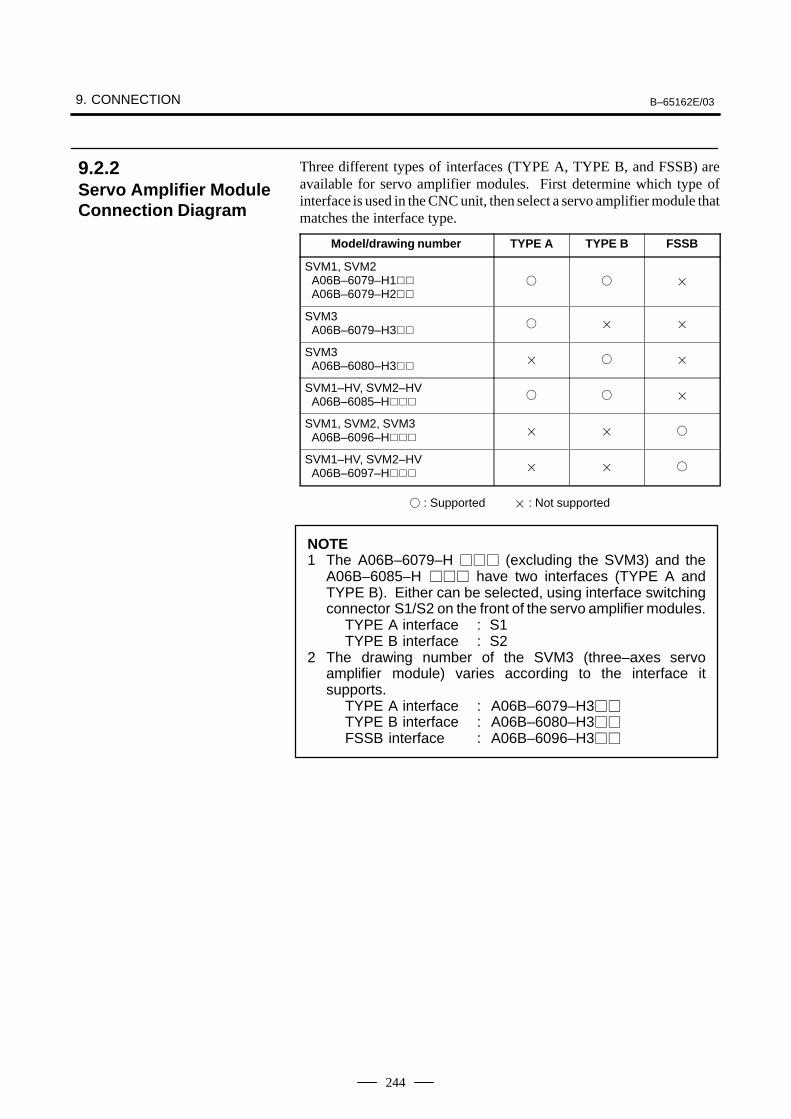
9. CONNECTION B–65162E/03
244
Three different types of interfaces (TYPE A, TYPE B, and FSSB) areavailable for servo amplifier modules. First determine which type ofinterface is used in the CNC unit, then select a servo amplifier module thatmatches the interface type.
Model/drawing number TYPE A TYPE B FSSB
SVM1, SVM2 A06B–6079–H1 A06B–6079–H2
SVM3 A06B–6079–H3
SVM3 A06B–6080–H3
SVM1–HV, SVM2–HV A06B–6085–H
SVM1, SVM2, SVM3 A06B–6096–H
SVM1–HV, SVM2–HV A06B–6097–H
: Supported : Not supported
NOTE1 The A06B–6079–H (excluding the SVM3) and the
A06B–6085–H have two interfaces (TYPE A andTYPE B). Either can be selected, using interface switchingconnector S1/S2 on the front of the servo amplifier modules.
TYPE A interface : S1TYPE B interface : S2
2 The drawing number of the SVM3 (three–axes servoamplifier module) varies according to the interface itsupports.
TYPE A interface : A06B–6079–H3TYPE B interface : A06B–6080–H3FSSB interface : A06B–6096–H3
9.2.2Servo Amplifier ModuleConnection Diagram
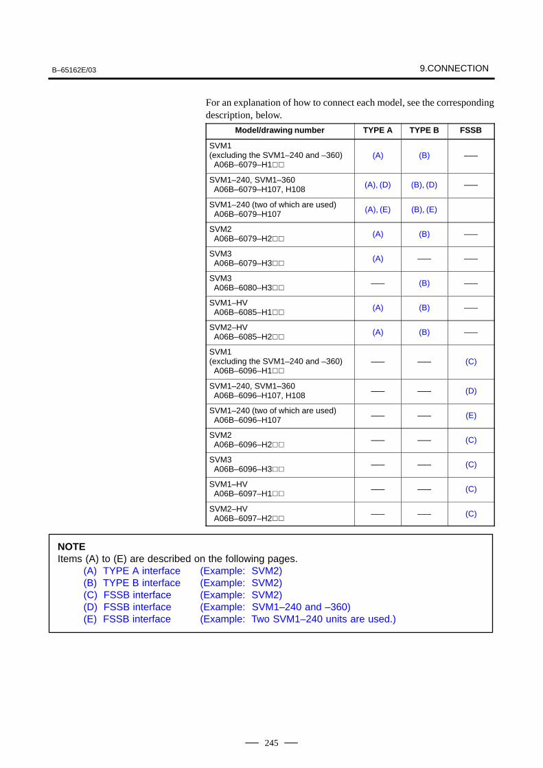
B–65162E/03 9.CONNECTION
245
For an explanation of how to connect each model, see the correspondingdescription, below.
Model/drawing number TYPE A TYPE B FSSB
SVM1(excluding the SVM1–240 and –360) A06B–6079–H1
(A) (B) –––
SVM1–240, SVM1–360 A06B–6079–H107, H108 (A), (D) (B), (D) –––
SVM1–240 (two of which are used) A06B–6079–H107 (A), (E) (B), (E)
SVM2 A06B–6079–H2
(A) (B) –––
SVM3 A06B–6079–H3
(A) ––– –––
SVM3 A06B–6080–H3
––– (B) –––
SVM1–HV A06B–6085–H1
(A) (B) –––
SVM2–HV A06B–6085–H2
(A) (B) –––
SVM1(excluding the SVM1–240 and –360) A06B–6096–H1
––– ––– (C)
SVM1–240, SVM1–360 A06B–6096–H107, H108 ––– ––– (D)
SVM1–240 (two of which are used) A06B–6096–H107 ––– ––– (E)
SVM2 A06B–6096–H2
––– ––– (C)
SVM3 A06B–6096–H3
––– ––– (C)
SVM1–HV A06B–6097–H1
––– ––– (C)
SVM2–HV A06B–6097–H2
––– ––– (C)
NOTEItems (A) to (E) are described on the following pages.
(A) TYPE A interface (Example: SVM2)(B) TYPE B interface (Example: SVM2)(C) FSSB interface (Example: SVM2)(D) FSSB interface (Example: SVM1–240 and –360)(E) FSSB interface (Example: Two SVM1–240 units are used.)
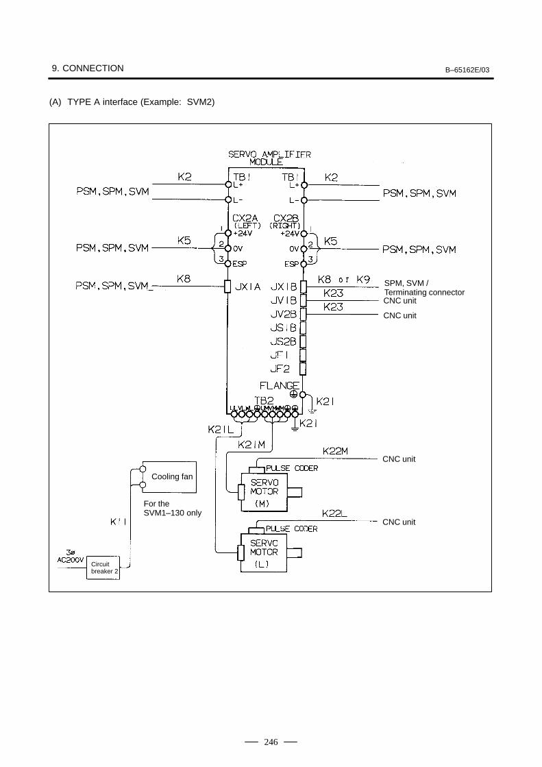
9. CONNECTION B–65162E/03
246
(A) TYPE A interface (Example: SVM2)
SPM, SVM / Terminating connectorCNC unit
CNC unit
CNC unit
CNC unit
Cooling fan
For theSVM1–130 only
Circuitbreaker 2
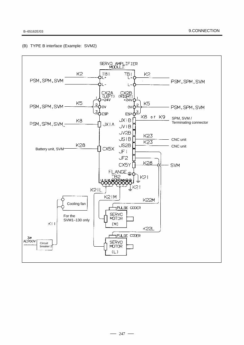
B–65162E/03 9.CONNECTION
247
(B) TYPE B interface (Example: SVM2)
SPM, SVM / Terminating connector
CNC unit
CNC unit
Cooling fan
For theSVM1–130 only
Circuitbreaker 2
Battery unit, SVM
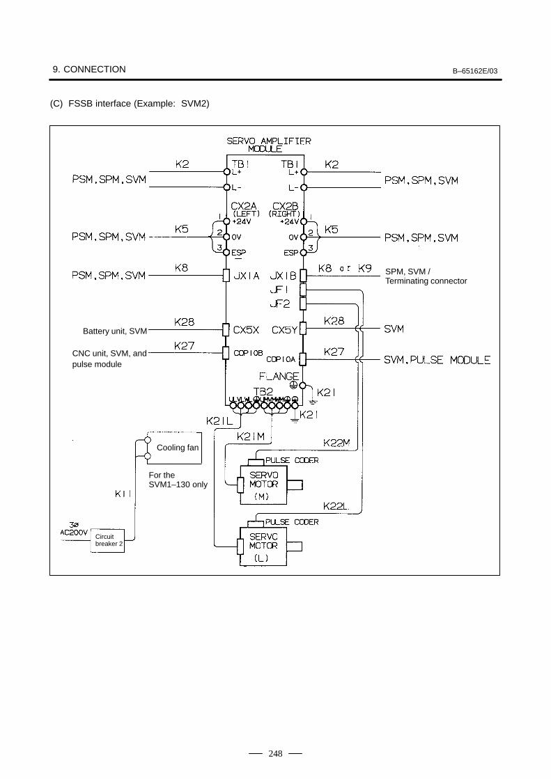
9. CONNECTION B–65162E/03
248
(C) FSSB interface (Example: SVM2)
SPM, SVM / Terminating connector
Cooling fan
For theSVM1–130 only
Circuitbreaker 2
Battery unit, SVM
CNC unit, SVM, and pulse module
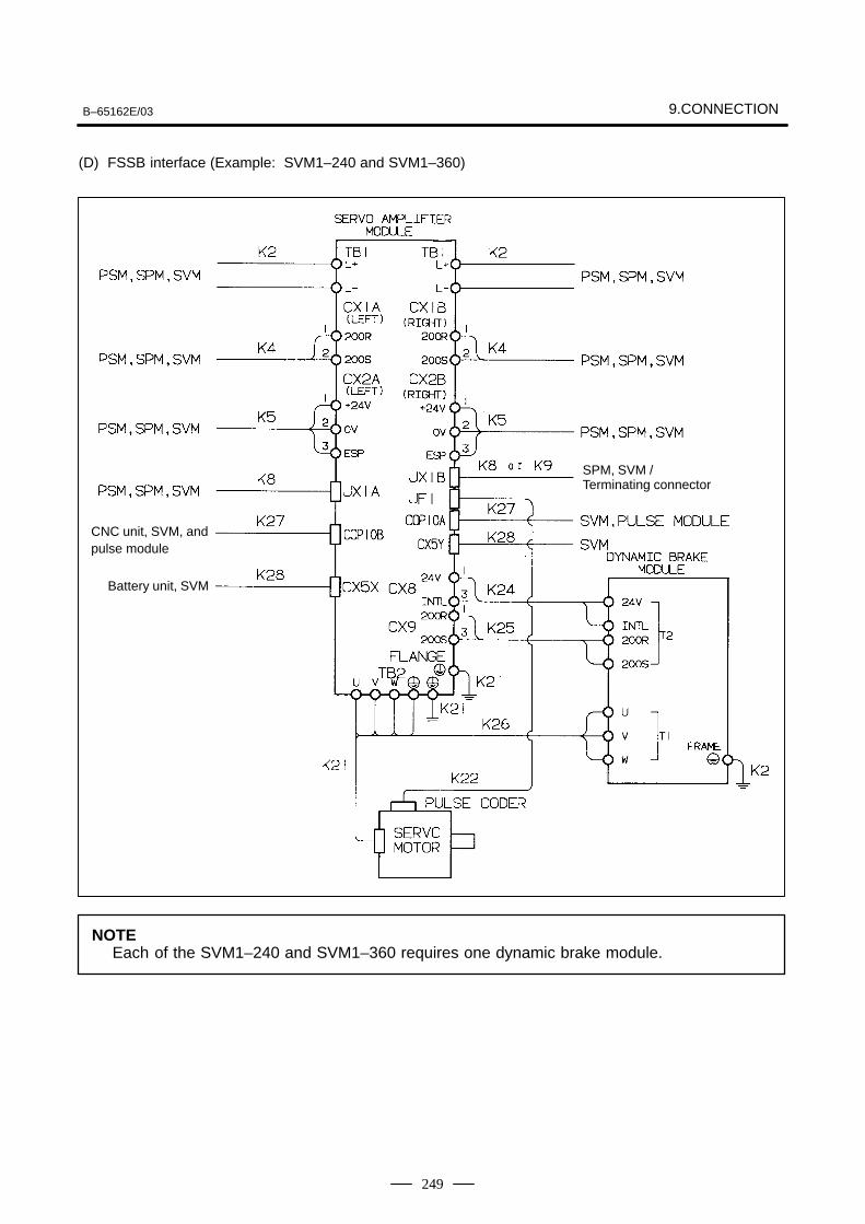
B–65162E/03 9.CONNECTION
249
(D) FSSB interface (Example: SVM1–240 and SVM1–360)
SPM, SVM / Terminating connector
Battery unit, SVM
CNC unit, SVM, and pulse module
NOTEEach of the SVM1–240 and SVM1–360 requires one dynamic brake module.
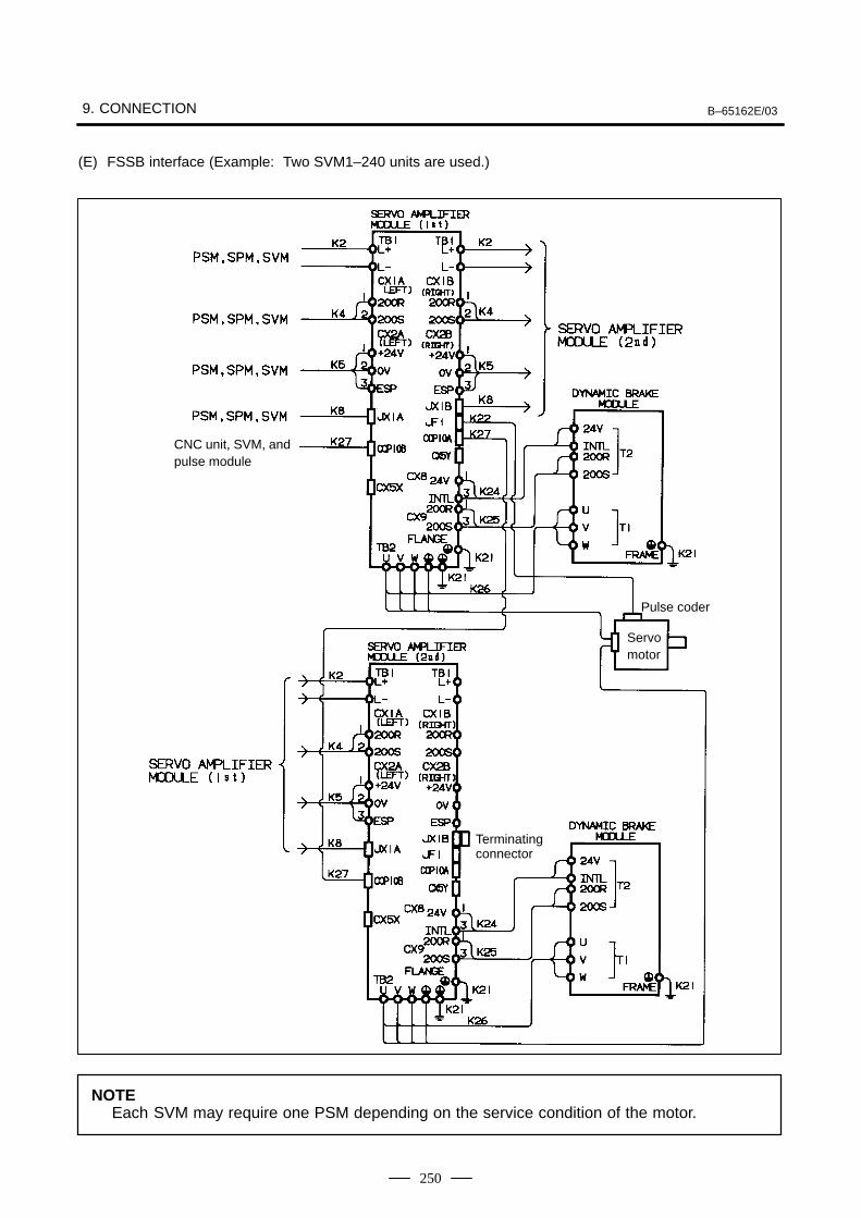
9. CONNECTION B–65162E/03
250
(E) FSSB interface (Example: Two SVM1–240 units are used.)
CNC unit, SVM, and pulse module
Pulse coder
Servomotor
Terminating connector
NOTEEach SVM may require one PSM depending on the service condition of the motor.
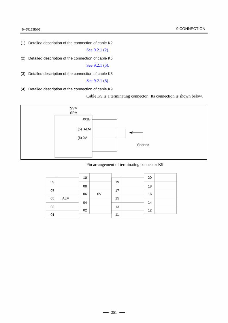
B–65162E/03 9.CONNECTION
251
(1) Detailed description of the connection of cable K2
See 9.2.1 (2).
(2) Detailed description of the connection of cable K5
See 9.2.1 (5).
(3) Detailed description of the connection of cable K8
See 9.2.1 (8).
(4) Detailed description of the connection of cable K9
Cable K9 is a terminating connector. Its connection is shown below.
Shorted
JX1B
(5) IALM
(6) 0V
SVMSPM
Pin arrangement of terminating connector K9
IALM
09
07
05
01
03
10
08
06
02
04
19
17
15
11
13
0V
20
18
16
12
14
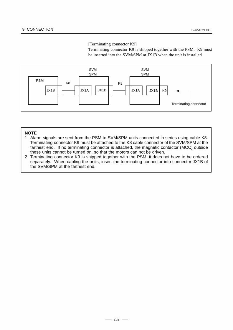
9. CONNECTION B–65162E/03
252
[Terminating connector K9]Terminating connector K9 is shipped together with the PSM. K9 mustbe inserted into the SVM/SPM at JX1B when the unit is installed.
PSMK8 K8
JX1B JX1A JX1B JX1A JX1B K9
SVMSPM
SVMSPM
Terminating connector
NOTE1 Alarm signals are sent from the PSM to SVM/SPM units connected in series using cable K8.
Terminating connector K9 must be attached to the K8 cable connector of the SVM/SPM at thefarthest end. If no terminating connector is attached, the magnetic contactor (MCC) outsidethese units cannot be turned on, so that the motors can not be driven.
2 Terminating connector K9 is shipped together with the PSM; it does not have to be orderedseparately. When cabling the units, insert the terminating connector into connector JX1B ofthe SVM/SPM at the farthest end.
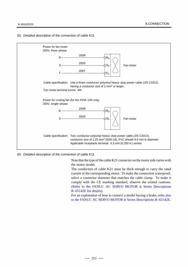
B–65162E/03 9.CONNECTION
253
(5) Detailed description of the connection of cable K11
R
S
T
200R
200S
200T
R0
S0
T0
Fan motor
Power for fan motor200V, three–phase
Cable specification: Use a three–conductor polyvinyl heavy–duty power cable (JIS C3312) having a conductor size of 2 mm2 or larger.
Fan motor terminal screw: M4
R
S
200R
200S
R0
S0 Fan motor
Power for cooling fan (for the SVM–130 only)200V, single–phase
Cable specification: Two–conductor polyvinyl heavy–duty power cable (JIS C3312), conductor size of 1.25 mm2 (50/0.18), PVC sheath 9.6 mm in diameterApplicable receptacle terminal: 6.3 mm (0.250 in.) series
(6) Detailed description of the connection of cable K11
Note that the type of the cable K21 connector on the motor side varies withthe motor model.The conductors of cable K21 must be thick enough to carry the ratedcurrent of the corresponding motor. To make the connection waterproof,select a connector diameter that matches the cable clamp. To make itcomply with the CE marking standard, observe the related cautions.(Refer to the FANUC AC SERVO MOTOR α Series DescriptionsB–65142E for details).For an explanation of how to connect a model having a brake, refer alsoto the FANUC AC SERVO MOTOR α Series Descriptions B–65142E.
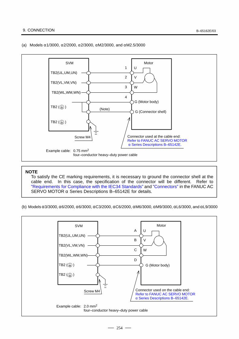
9. CONNECTION B–65162E/03
254
(a) Models α1/3000, α2/2000, α2/3000, αM2/3000, and αM2.5/3000
Connector used at the cable end: Refer to FANUC AC SERVO MOTOR α Series Descriptions B–65142E.
Motor
TB2 ( )
SVM
TB2(UL,UM,UN)
G (Motor body)
TB2(VL,VM,VN)
TB2(WL,WM,WN)
TB2 ( )
1
2
3
4
U
V
W
Screw M4
(Note)G (Connector shell)
Example cable: 0.75 mm2 four–conductor heavy–duty power cable
NOTETo satisfy the CE marking requirements, it is necessary to ground the connector shell at thecable end. In this case, the specification of the connector will be different. Refer to”Requirements for Compliance with the IEC34 Standards” and ”Connectors” in the FANUC ACSERVO MOTOR α Series Descriptions B–65142E for details.
(b) Models α3/3000, α6/2000, α6/3000, αC3/2000, αC6/2000, αM6/3000, αM9/3000, αL6/3000, and αL9/3000
MotorSVM
TB2(UL,UM,UN)
TB2(VL,VM,VN)
TB2(WL,WM,WN)
A
B
C
D
U
V
W
TB2 ( )
TB2 ( )
G (Motor body)
Screw M4 Connector used on the cable end: Refer to FANUC AC SERVO MOTOR α Series Descriptions B–65142E.
Example cable: 2.0 mm2 four–conductor heavy–duty power cable
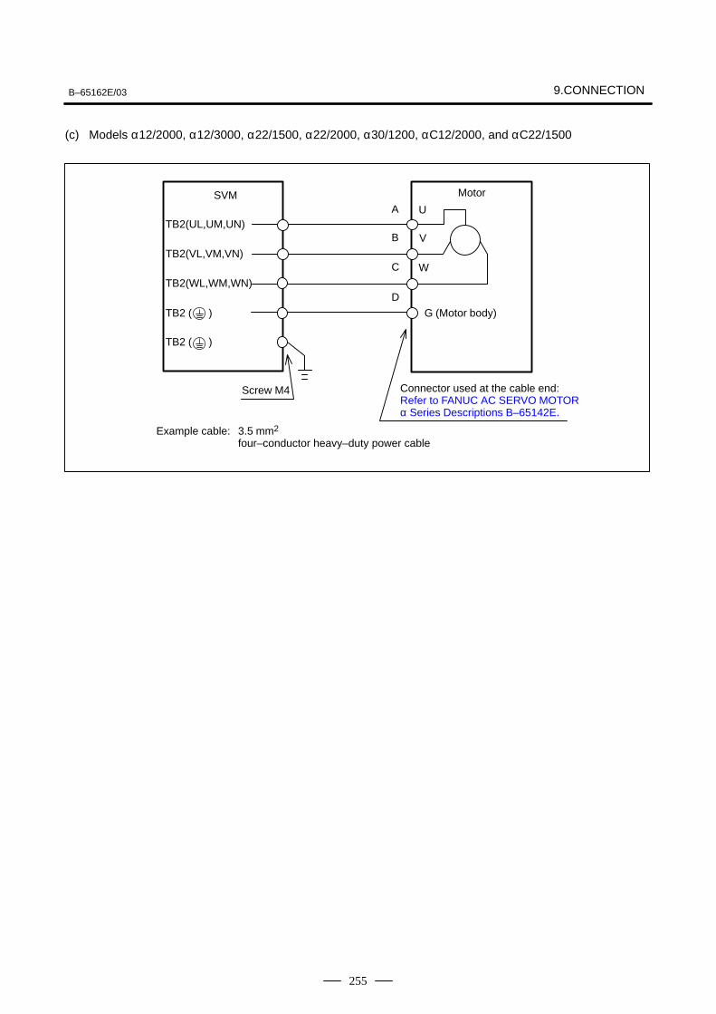
B–65162E/03 9.CONNECTION
255
(c) Models α12/2000, α12/3000, α22/1500, α22/2000, α30/1200, αC12/2000, and αC22/1500
SVM
TB2(UL,UM,UN)
TB2(VL,VM,VN)
TB2(WL,WM,WN)
A
B
C
D
U
V
W
TB2 ( )
TB2 ( )
Connector used at the cable end: Refer to FANUC AC SERVO MOTOR α Series Descriptions B–65142E.
Screw M4
Example cable: 3.5 mm2 four–conductor heavy–duty power cable
Motor
G (Motor body)
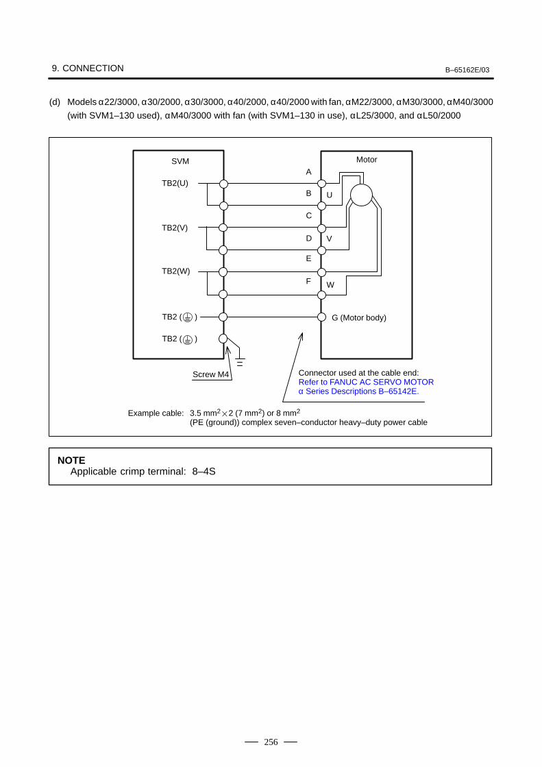
9. CONNECTION B–65162E/03
256
(d) Models α22/3000, α30/2000, α30/3000, α40/2000, α40/2000 with fan, αM22/3000, αM30/3000, αM40/3000
(with SVM1–130 used), αM40/3000 with fan (with SVM1–130 in use), αL25/3000, and αL50/2000
SVM
TB2(U)
TB2(V)
TB2(W)
A
B
C
D
U
E
F W
V
TB2 ( )
TB2 ( )
Connector used at the cable end: Refer to FANUC AC SERVO MOTOR α Series Descriptions B–65142E.
Screw M4
Example cable: 3.5 mm22 (7 mm2) or 8 mm2 (PE (ground)) complex seven–conductor heavy–duty power cable
Motor
G (Motor body)
NOTEApplicable crimp terminal: 8–4S
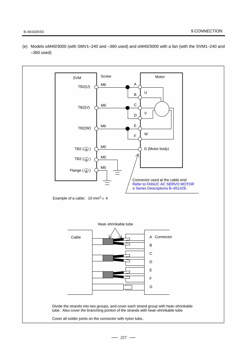
B–65162E/03 9.CONNECTION
257
(e) Models αM40/3000 (with SMV1–240 and –360 used) and αM40/3000 with a fan (with the SVM1–240 and
–360 used)
Cable
SVM
TB2(U)
TB2(V)
TB2(W)
A
B
C
D
U
Screw
E
F W
V
M6
M6
M6
M5
M5
M5
TB2 ( )
TB2 ( )
Flange ( )
Connector used at the cable end: Refer to FANUC AC SERVO MOTOR α Series Descriptions B–65142E.
Example of a cable: 10 mm2 4
Motor
G (Motor body)
B
C
D
E
F
G
A
Heat–shrinkable tube
Connector
Divide the strands into two groups, and cover each strand group with heat–shrinkabletube. Also cover the branching portion of the strands with heat–shrinkable tube
Cover all solder joints on the connector with nylon tube..
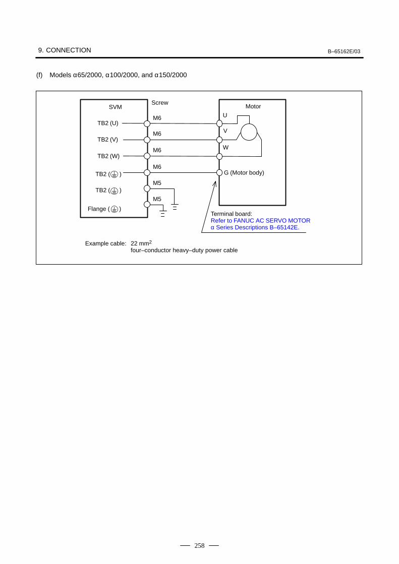
9. CONNECTION B–65162E/03
258
(f) Models α65/2000, α100/2000, and α150/2000
SVM
TB2 (U)
TB2 (V)
TB2 (W)
U
V
W
M6
M6
M6
M6
M5
M5
TB2 ( )
TB2 ( )
Flange ( )
Motor
G (Motor body)
Terminal board: Refer to FANUC AC SERVO MOTOR α Series Descriptions B–65142E.
Example cable: 22 mm2
four–conductor heavy–duty power cable
Screw
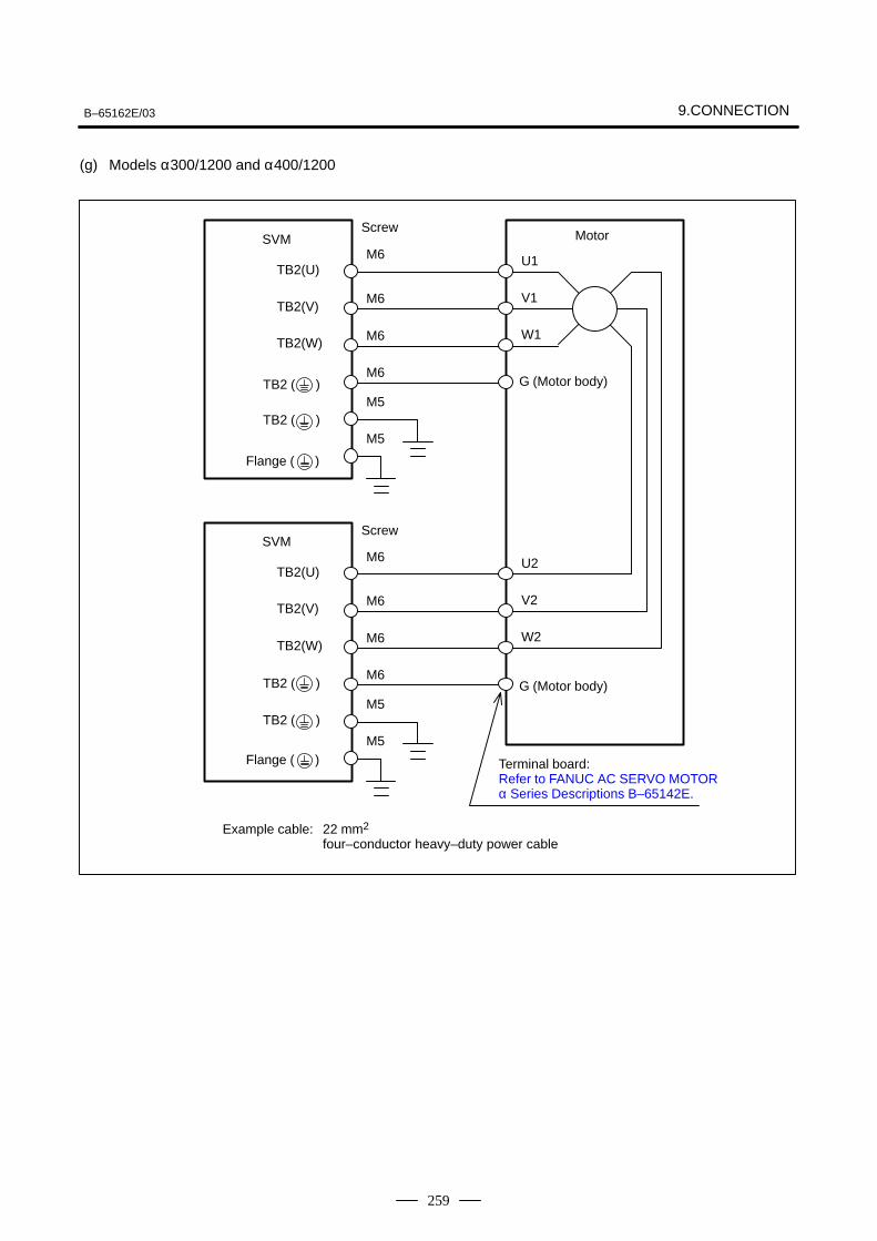
B–65162E/03 9.CONNECTION
259
(g) Models α300/1200 and α400/1200
U1
V1
W1
U2
V2
W2
SVM
TB2(U)
TB2(V)
TB2(W)
M6
M6
M6
M6
M5
M5
SVM
TB2(U)
TB2(V)
TB2(W)
M6
M6
M6
M6
M5
M5
TB2 ( )
TB2 ( )
Flange ( )
Motor
G (Motor body)
Terminal board: Refer to FANUC AC SERVO MOTOR α Series Descriptions B–65142E.
Example cable: 22 mm2
four–conductor heavy–duty power cable
TB2 ( )
TB2 ( )
Flange ( )
G (Motor body)
Screw
Screw
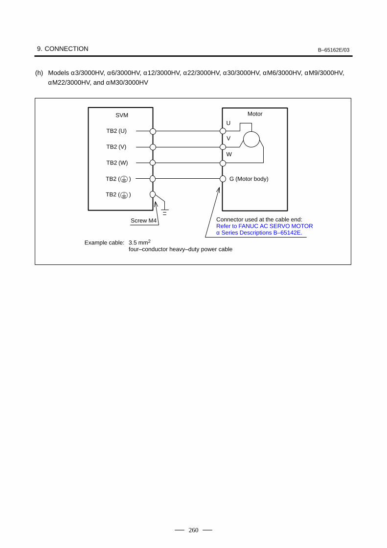
9. CONNECTION B–65162E/03
260
(h) Models α3/3000HV, α6/3000HV, α12/3000HV, α22/3000HV, α30/3000HV, αM6/3000HV, αM9/3000HV,
αM22/3000HV, and αM30/3000HV
SVM
TB2 (U)
TB2 (V)
TB2 (W)
U
V
W
TB2 ( )
TB2 ( )
Connector used at the cable end: Refer to FANUC AC SERVO MOTOR α Series Descriptions B–65142E.
Screw M4
Example cable: 3.5 mm2 four–conductor heavy–duty power cable
Motor
G (Motor body)
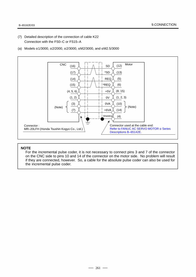
B–65162E/03 9.CONNECTION
261
(7) Detailed description of the connection of cable K22
Connection with the FS0–C or FS15–A
(a) Models α1/3000, α2/2000, α2/3000, αM2/3000, and αM2.5/3000
CNC Motor(16)
(15)
(14)
(13)
(12)
(10)
(8, 15)
(17)
(5)
(6)
(1, 2, 3)
(14)
(4)
(4, 5, 6)
(1, 2)
(3)
(7)(Note) (Note)
SD
*SD
REQ
+5V
*REQ
0V
0VA
+6VA
Shielding
Connector :MR–20LFH (Honda Tsushin Kogyo Co., Ltd.)
Connector used at the cable end: Refer to FANUC AC SERVO MOTOR α Series Descriptions B–65142E.
NOTEFor the incremental pulse coder, it is not necessary to connect pins 3 and 7 of the connectoron the CNC side to pins 10 and 14 of the connector on the motor side. No problem will resultif they are connected, however. So, a cable for the absolute pulse coder can also be used forthe incremental pulse coder.

9. CONNECTION B–65162E/03
262
Connector :MR–20LFH (Honda Tsushin Kogyo Co., Ltd.)
Relay unit Motor(16)
(15)
(14)
(13)
(12)
(10)
(8, 15)
(17)
(5)
(6)
(1, 2, 3)
(14)
(4)
(4, 5)
(1, 2)
(3)
(6)
SD
*SD
REQ
+5V
*REQ
0V
0VA
+6VA
Shielding
Connector used at the cable end: Refer to FANUC AC SERVO MOTOR α Series Descriptions B–65142E.
NOTECables used in common for (a) and (b) : +5V, 0V...0.5 mm2 or larger2
(for length of 14 m or less): +6VA, 0VA...0.5 mm2 or larger: SD, *SD, REQ, *REQ...twisted pair 0.18 mm2
or largerIf the cable is 14 m or longer, keep the electrical resistance across each of the 0V and +5V linesto within 0.5Ω .
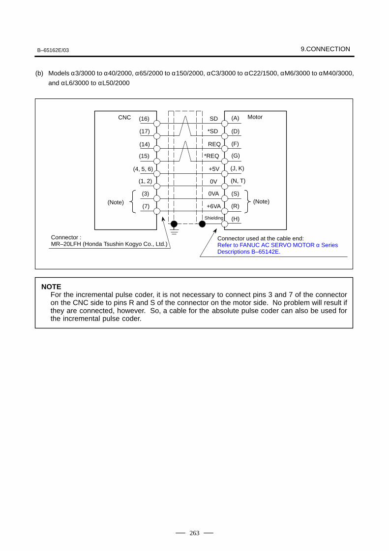
B–65162E/03 9.CONNECTION
263
(b) Models α3/3000 to α40/2000, α65/2000 to α150/2000, αC3/3000 to αC22/1500, αM6/3000 to αM40/3000,
and αL6/3000 to αL50/2000
(Note)(Note)
|
(16)
(15)
(14)
(D)
(A)
(S)
(J, K)
(17)
(F)
(G)
(N, T)
(R)
(H)
(4, 5, 6)
(1, 2)
(3)
(7)
SD
*SD
REQ
+5V
*REQ
0V
0VA
+6VA
Shielding
CNC Motor
Connector :MR–20LFH (Honda Tsushin Kogyo Co., Ltd.)
Connector used at the cable end: Refer to FANUC AC SERVO MOTOR α Series Descriptions B–65142E.
NOTEFor the incremental pulse coder, it is not necessary to connect pins 3 and 7 of the connectoron the CNC side to pins R and S of the connector on the motor side. No problem will result ifthey are connected, however. So, a cable for the absolute pulse coder can also be used forthe incremental pulse coder.
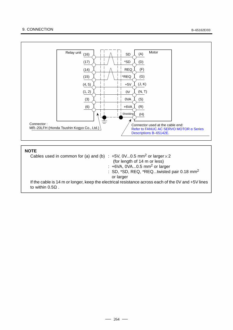
9. CONNECTION B–65162E/03
264
Connector :MR–20LFH (Honda Tsushin Kogyo Co., Ltd.)
Relay unit Motor(16)
(15)
(14)
(17)
(4, 5)
(1, 2)
(3)
(6)
SD
*SD
REQ
+5V
*REQ
0V
0VA
+6VA
Shielding
Connector used at the cable end: Refer to FANUC AC SERVO MOTOR α Series Descriptions B–65142E.
(D)
(A)
(S)
(J, K)
(F)
(G)
(N, T)
(R)
(H)
NOTECables used in common for (a) and (b) : +5V, 0V...0.5 mm2 or larger2
(for length of 14 m or less): +6VA, 0VA...0.5 mm2 or larger: SD, *SD, REQ, *REQ...twisted pair 0.18 mm2
or largerIf the cable is 14 m or longer, keep the electrical resistance across each of the 0V and +5V linesto within 0.5Ω .
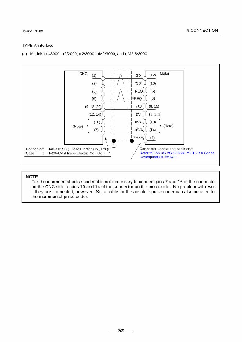
B–65162E/03 9.CONNECTION
265
TYPE A interface
(a) Models α1/3000, α2/2000, α2/3000, αM2/3000, and αM2.5/3000
CNC Motor
(13)
(12)
(10)
(8, 15)
(5)
(6)
(1, 2, 3)
(14)
(4)
(Note) (Note)
SD
*SD
REQ
+5V
*REQ
0V
0VA
+6VA
Shielding
Connector : FI40–2015S (Hirose Electric Co., Ltd.)Case : FI–20–CV (Hirose Electric Co., Ltd.)
Connector used at the cable end: Refer to FANUC AC SERVO MOTOR α Series Descriptions B–65142E.
(1)
(6)
(5)
(2)
(9, 18, 20)
(12, 14)
(16)
(7)
NOTEFor the incremental pulse coder, it is not necessary to connect pins 7 and 16 of the connectoron the CNC side to pins 10 and 14 of the connector on the motor side. No problem will resultif they are connected, however. So, a cable for the absolute pulse coder can also be used forthe incremental pulse coder.
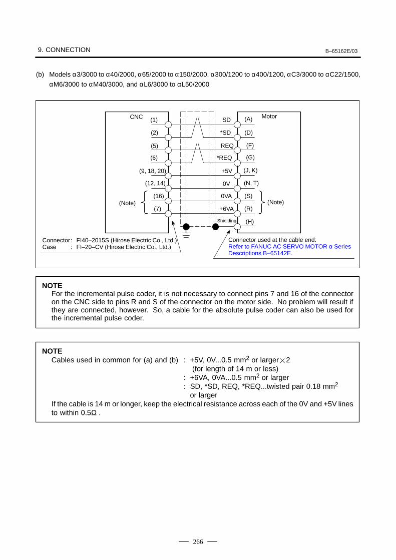
9. CONNECTION B–65162E/03
266
(b) Models α3/3000 to α40/2000, α65/2000 to α150/2000, α300/1200 to α400/1200, αC3/3000 to αC22/1500,
αM6/3000 to αM40/3000, and αL6/3000 to αL50/2000
CNC Motor
(Note) (Note)
SD
*SD
REQ
+5V
*REQ
0V
0VA
+6VA
Shielding
Connector : FI40–2015S (Hirose Electric Co., Ltd.)Case : FI–20–CV (Hirose Electric Co., Ltd.)
Connector used at the cable end: Refer to FANUC AC SERVO MOTOR α Series Descriptions B–65142E.
(1)
(6)
(5)
(2)
(9, 18, 20)
(12, 14)
(16)
(7)
(D)
(A)
(S)
(J, K)
(F)
(G)
(N, T)
(R)
(H)
NOTEFor the incremental pulse coder, it is not necessary to connect pins 7 and 16 of the connectoron the CNC side to pins R and S of the connector on the motor side. No problem will result ifthey are connected, however. So, a cable for the absolute pulse coder can also be used forthe incremental pulse coder.
NOTECables used in common for (a) and (b) : +5V, 0V...0.5 mm2 or larger2
(for length of 14 m or less): +6VA, 0VA...0.5 mm2 or larger: SD, *SD, REQ, *REQ...twisted pair 0.18 mm2
or largerIf the cable is 14 m or longer, keep the electrical resistance across each of the 0V and +5V linesto within 0.5Ω .
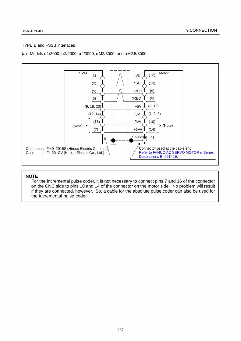
B–65162E/03 9.CONNECTION
267
TYPE B and FSSB interfaces
(a) Models α1/3000, α2/2000, α2/3000, αM2/3000, and αM2.5/3000
SVM Motor
(13)
(12)
(10)
(8, 15)
(5)
(6)
(1, 2, 3)
(14)
(4)
(Note) (Note)
SD
*SD
REQ
+5V
*REQ
0V
0VA
+6VA
Shielding
Connector : FI40–2015S (Hirose Electric Co., Ltd.)Case : FI–20–CV (Hirose Electric Co., Ltd.)
Connector used at the cable end: Refer to FANUC AC SERVO MOTOR α Series Descriptions B–65142E.
(1)
(6)
(5)
(2)
(9, 18, 20)
(12, 14)
(16)
(7)
NOTEFor the incremental pulse coder, it is not necessary to connect pins 7 and 16 of the connectoron the CNC side to pins 10 and 14 of the connector on the motor side. No problem will resultif they are connected, however. So, a cable for the absolute pulse coder can also be used forthe incremental pulse coder.

9. CONNECTION B–65162E/03
268
(b) Models α3/3000 to α40/2000, α65/2000 to α150/2000, α300/1200 to α400/1200, αC3/2000 to αC22/1500,
αM6/3000 to αM40/3000, and αL6/3000 to αL50/2000
SVM Motor
(Note) (Note)
SD
*SD
REQ
+5V
*REQ
0V
0VA
+6VA
Shielding
Connector : FI40–2015S (Hirose Electric Co., Ltd.)Case : FI–20–CV (Hirose Electric Co., Ltd.)
Connector used at the cable end: Refer to FANUC AC SERVO MOTOR α Series Descriptions B–65142E.
(1)
(6)
(5)
(2)
(9, 18, 20)
(12, 14)
(16)
(7)
(D)
(A)
(S)
(J, K)
(F)
(G)
(N, T)
(R)
(H)
NOTEFor the incremental pulse coder, it is not necessary to connect pins 7 and 16 of the connectoron the CNC side to pins R and S of the connector on the motor side. No problem will result ifthey are connected, however. So, a cable for the absolute pulse coder can also be used forthe incremental pulse coder.
NOTECables used in common for (a) and (b) : +5V, 0V...0.5 mm2 or larger2
(for length of 14 m or less): +6VA, 0VA...0.5 mm2 or larger: SD, *SD, REQ, *REQ...twisted pair 0.18 mm2
or largerIf the cable is 14 m or longer, keep the electrical resistance across each of the 0V and +5V linesto within 0.5Ω.
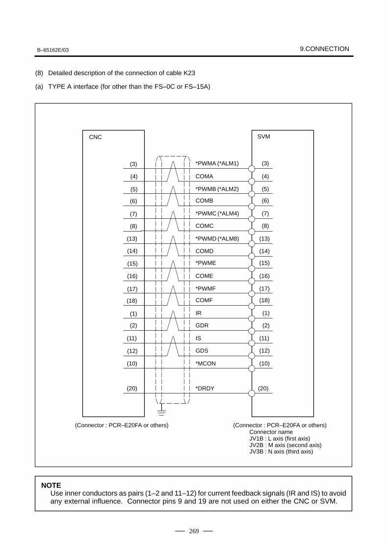
B–65162E/03 9.CONNECTION
269
(8) Detailed description of the connection of cable K23
(a) TYPE A interface (for other than the FS–0C or FS–15A)
SVM
(3)
(6)
(5)
(4)
(3)
(13)
(7)
(4)
(5)
(6)
(8)
(14)
(7)
(8)
(13)
(14)
CNC
(15)
(18)
(17)
(16)
(15)
(11)
(1)
(16)
(17)
(18)
(2)
(12)
(1)
(2)
(11)
(12)
(10)(10)
(20)(20)
*PWMA (*ALM1)
COMA
*PWMB (*ALM2)
COMB
*PWMC (*ALM4)
COMC
*PWMD (*ALM8)
COMD
*PWME
COME
*PWMF
COMF
IR
GDR
IS
GDS
*MCON
*DRDY
(Connector : PCR–E20FA or others) (Connector : PCR–E20FA or others)Connector nameJV1B : L axis (first axis)JV2B : M axis (second axis)JV3B : N axis (third axis)
NOTEUse inner conductors as pairs (1–2 and 11–12) for current feedback signals (IR and IS) to avoidany external influence. Connector pins 9 and 19 are not used on either the CNC or SVM.
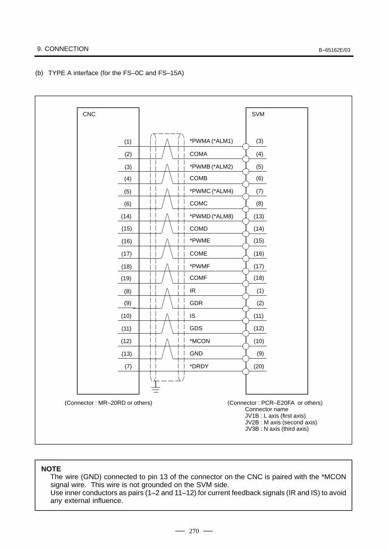
9. CONNECTION B–65162E/03
270
(b) TYPE A interface (for the FS–0C and FS–15A)
Connector nameJV1B : L axis (first axis)JV2B : M axis (second axis)JV3B : N axis (third axis)
SVM
(1)
(4)
(3)
(4)
(3)
(13)
(7)
(2)
(5)
(6)
(8)
(14)
(5)
(6)
(14)
(15)
(16)
(19)
(18)
(16)
(15)
(11)
(1)
(17)
(17)
(18)
(2)
(12)
(8)
(9)
(10)
(11)
(10)(12)
*PWMA (*ALM1)
COMA
*PWMB (*ALM2)
COMB
*PWMC (*ALM4)
COMC
*PWMD (*ALM8)
COMD
*PWME
COME
*PWMF
COMF
IR
GDR
IS
GDS
*MCON
(Connector : MR–20RD or others) (Connector : PCR–E20FA or others)
(9)(13)
(20)(7)
GND
*DRDY
CNC
NOTEThe wire (GND) connected to pin 13 of the connector on the CNC is paired with the *MCONsignal wire. This wire is not grounded on the SVM side.Use inner conductors as pairs (1–2 and 11–12) for current feedback signals (IR and IS) to avoidany external influence.
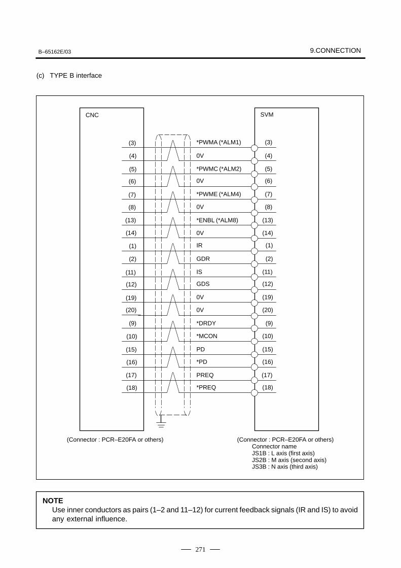
B–65162E/03 9.CONNECTION
271
(c) TYPE B interface
SVM
(3)
(6)
(5)
(4)
(3)
(13)
(7)
(4)
(5)
(6)
(8)
(14)
(7)
(8)
(13)
(14)
CNC
(1)
(12)
(11)
(2)
(1)
(9)
(19)
(2)
(11)
(12)
(20)
(10)
(19)
(20)
(9)
(10)
(15)(15)
(17)(17)
*PWMA (*ALM1)
0V
*PWMC (*ALM2)
0V
*PWME (*ALM4)
0V
*ENBL (*ALM8)
0V
IR
GDR
IS
GDS
0V
0V
*DRDY
*MCON
PD
PREQ
(Connector : PCR–E20FA or others) (Connector : PCR–E20FA or others)Connector nameJS1B : L axis (first axis)JS2B : M axis (second axis)JS3B : N axis (third axis)
(16)(16) *PD
(18)(18) *PREQ
NOTEUse inner conductors as pairs (1–2 and 11–12) for current feedback signals (IR and IS) to avoidany external influence.
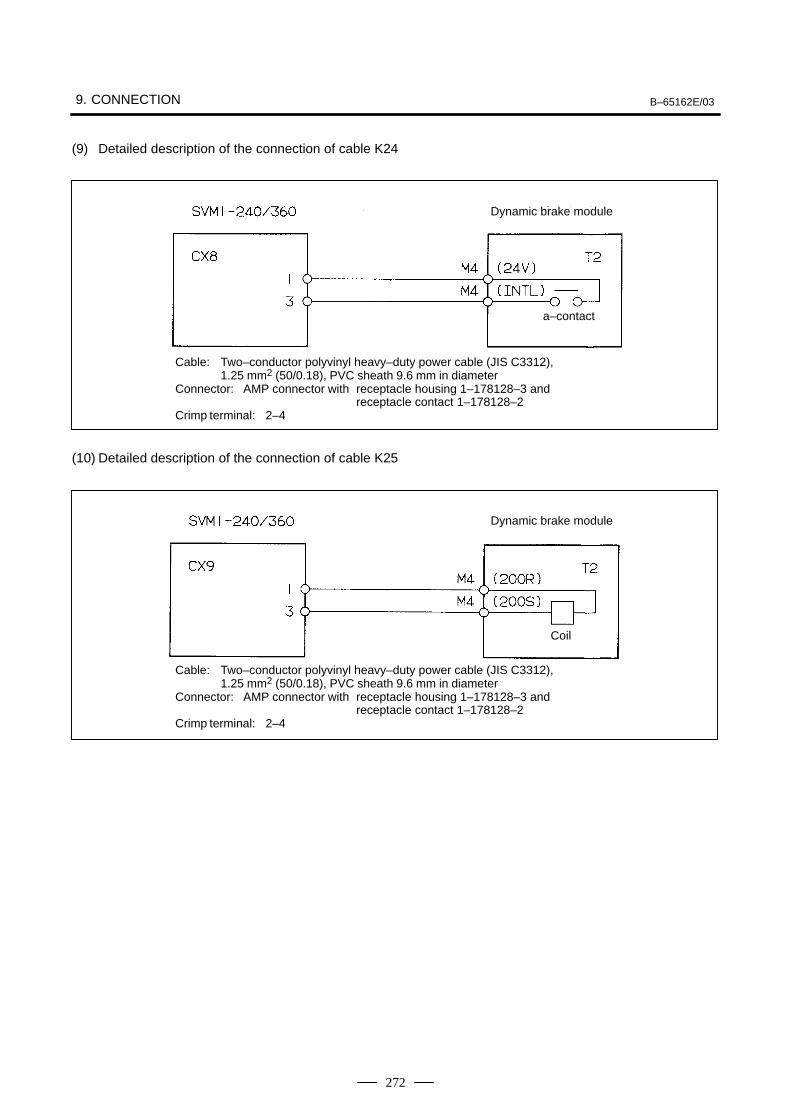
9. CONNECTION B–65162E/03
272
(9) Detailed description of the connection of cable K24
Dynamic brake module
a–contact
Cable: Two–conductor polyvinyl heavy–duty power cable (JIS C3312), 1.25 mm2 (50/0.18), PVC sheath 9.6 mm in diameter
Connector: AMP connector with receptacle housing 1–178128–3 and receptacle contact 1–178128–2
Crimp terminal: 2–4
(10) Detailed description of the connection of cable K25
Dynamic brake module
Cable: Two–conductor polyvinyl heavy–duty power cable (JIS C3312), 1.25 mm2 (50/0.18), PVC sheath 9.6 mm in diameter
Connector: AMP connector with receptacle housing 1–178128–3 and receptacle contact 1–178128–2
Crimp terminal: 2–4
Coil
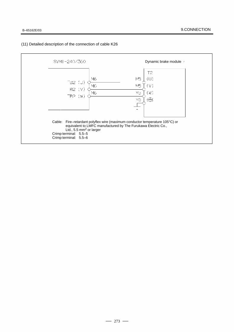
B–65162E/03 9.CONNECTION
273
(11) Detailed description of the connection of cable K26
Dynamic brake module
Cable: Fire–retardant polyflex wire (maximum conductor temperature 105°C) or equivalent to LMFC manufactured by The Furukawa Electric Co., Ltd., 5.5 mm2 or larger
Crimp terminal: 5.5–5Crimp terminal: 5.5–6
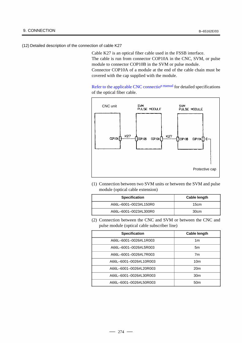
9. CONNECTION B–65162E/03
274
(12) Detailed description of the connection of cable K27
Cable K27 is an optical fiber cable used in the FSSB interface.The cable is run from connector COP10A in the CNC, SVM, or pulsemodule to connector COP10B in the SVM or pulse module.Connector COP10A of a module at the end of the cable chain must becovered with the cap supplied with the module.
Refer to the applicable CNC connection manual for detailed specificationsof the optical fiber cable.
CNC unit
Protective cap
(1) Connection between two SVM units or between the SVM and pulsemodule (optical cable extension)
Specification Cable length
A66L–6001–0023#L150R0 15cm
A66L–6001–0023#L300R0 30cm
(2) Connection between the CNC and SVM or between the CNC andpulse module (optical cable subscriber line)
Specification Cable length
A66L–6001–0026#L1R003 1m
A66L–6001–0026#L5R003 5m
A66L–6001–0026#L7R003 7m
A66L–6001–0026#L10R003 10m
A66L–6001–0026#L20R003 20m
A66L–6001–0026#L30R003 30m
A66L–6001–0026#L50R003 50m
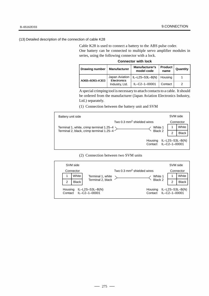
B–65162E/03 9.CONNECTION
275
(13) Detailed description of the connection of cable K28
Cable K28 is used to connect a battery to the ABS pulse coder.One battery can be connected to multiple servo amplifier modules inseries, using the following connector with a lock.
Connector with lock
Drawing number Manufacturer Manufacturer’smodel code
Productname Quantity
A06B–6093–K303Japan Aviation
ElectronicsIL–L2S–S3L–B(N) Housing 1
A06B–6093–K303 Electronics Industry, Ltd. IL–C2–1–00001 Contact 2
A special crimping tool is necessary to attach contacts to a cable. It shouldbe ordered from the manufacturer (Japan Aviation Electronics Industry,Ltd.) separately.
(1) Connection between the battery unit and SVM
1
2
White
Black
Battery unit side SVM side
Two 0.3 mm2 shielded wires
Terminal 1, white, crimp terminal 1.25–4Terminal 2, black, crimp terminal 1.25–4
White 1Black 2
Connector
Housing IL–L2S–S3L–B(N)Contact IL–C2–1–00001
(2) Connection between two SVM units
1
2
White
Black
SVM side
Two 0.3 mm2 shielded wires
White 1Black 2
Connector
Housing IL–L2S–S3L–B(N)Contact IL–C2–1–00001
1
2
White
Black
SVM side
Connector
Housing IL–L2S–S3L–B(N)Contact IL–C2–1–00001
Terminal 1, whiteTerminal 2, black
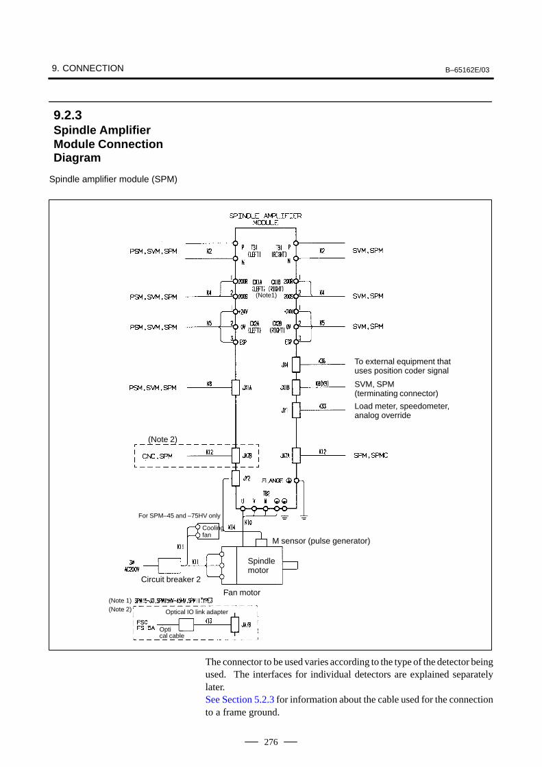
9. CONNECTION B–65162E/03
276
Spindle amplifier module (SPM)
To external equipment thatuses position coder signal
SVM, SPM(terminating connector)
Load meter, speedometer, analog override
(Note 2)
For SPM–45 and –75HV only
Coolingfan
M sensor (pulse generator)
Circuit breaker 2
Spindlemotor
Fan motor(Note 1)(Note 2) Optical IO link adapter
Optical cable
(Note1)
The connector to be used varies according to the type of the detector beingused. The interfaces for individual detectors are explained separatelylater.See Section 5.2.3 for information about the cable used for the connectionto a frame ground.
9.2.3Spindle AmplifierModule ConnectionDiagram
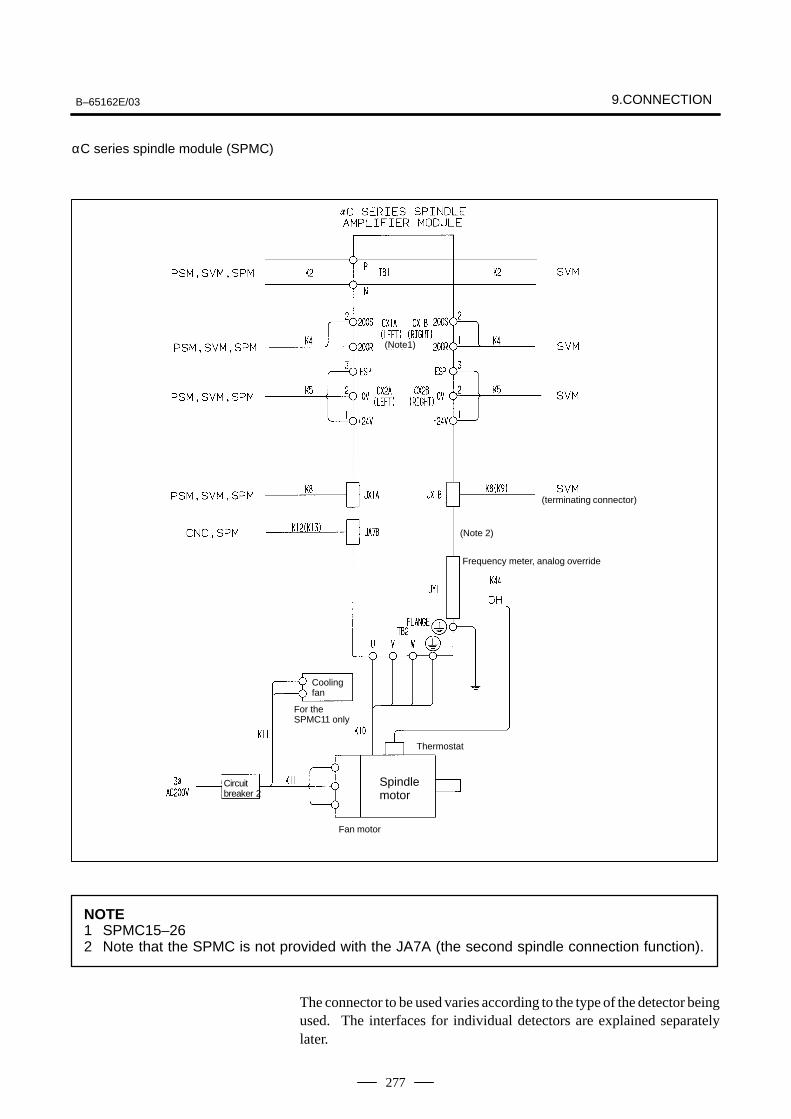
B–65162E/03 9.CONNECTION
277
αC series spindle module (SPMC)
(terminating connector)
(Note 2)
Frequency meter, analog override
Coolingfan
For the SPMC11 only
Thermostat
Circuit breaker 2
Spindlemotor
Fan motor
(Note1)
NOTE1 SPMC15–262 Note that the SPMC is not provided with the JA7A (the second spindle connection function).
The connector to be used varies according to the type of the detector beingused. The interfaces for individual detectors are explained separatelylater.
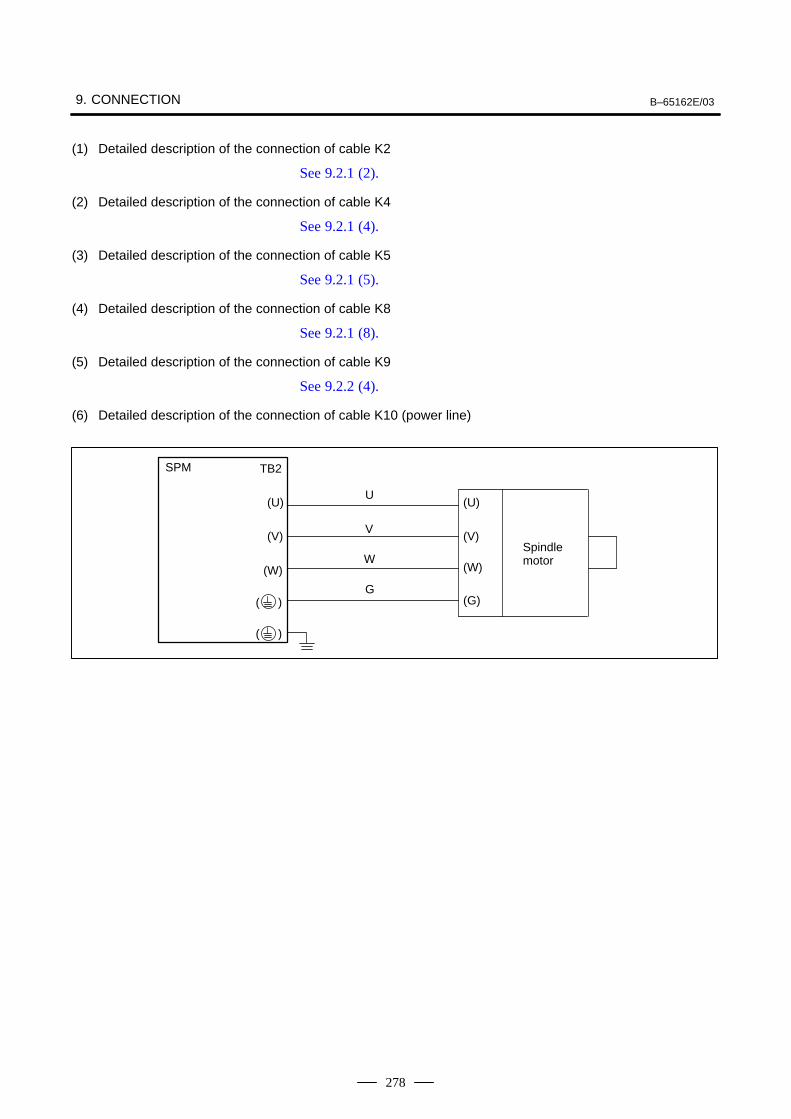
9. CONNECTION B–65162E/03
278
(1) Detailed description of the connection of cable K2
See 9.2.1 (2).
(2) Detailed description of the connection of cable K4
See 9.2.1 (4).
(3) Detailed description of the connection of cable K5
See 9.2.1 (5).
(4) Detailed description of the connection of cable K8
See 9.2.1 (8).
(5) Detailed description of the connection of cable K9
See 9.2.2 (4).
(6) Detailed description of the connection of cable K10 (power line)
SPM TB2
U
V
(U)
(V)
(W)
( )
W
G
(U)
(V)
(W)
(G)
Spindle motor
( )
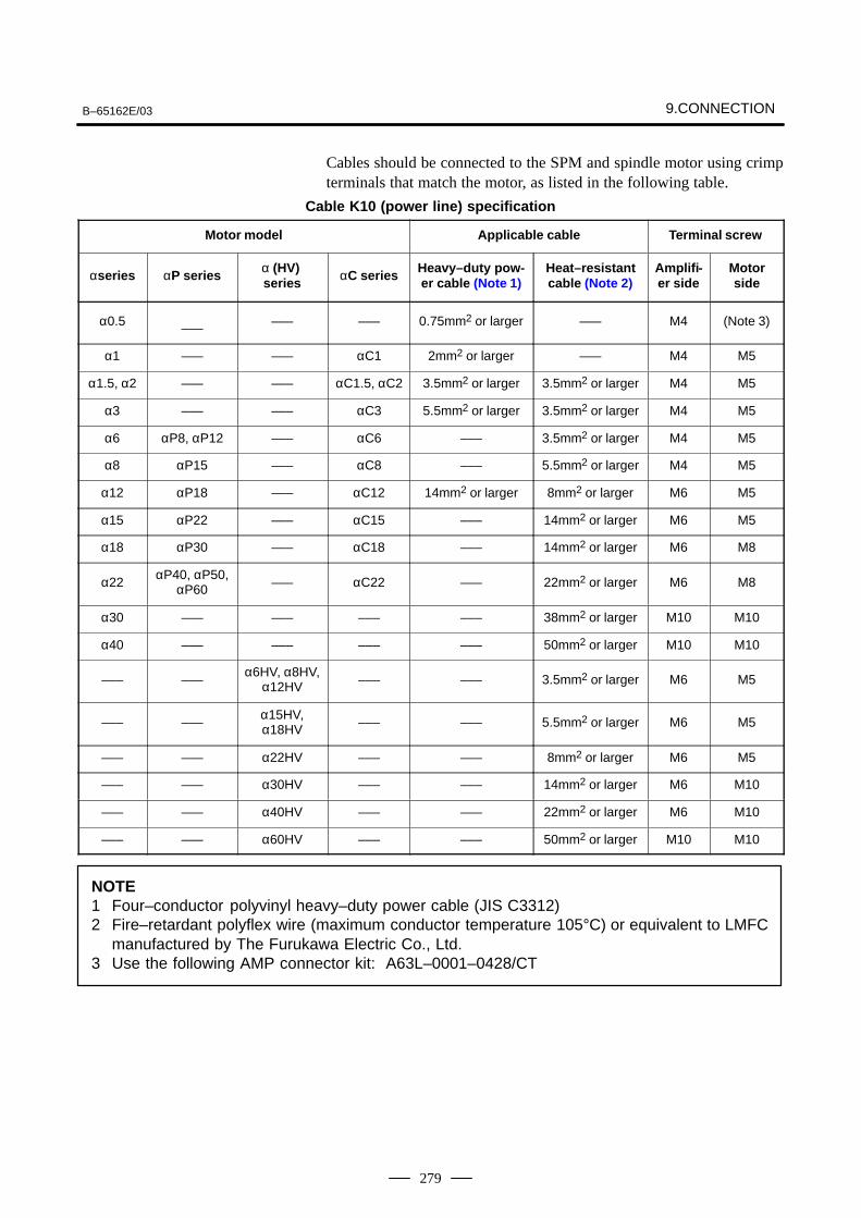
B–65162E/03 9.CONNECTION
279
Cables should be connected to the SPM and spindle motor using crimpterminals that match the motor, as listed in the following table.
Cable K10 (power line) specification
Motor model Applicable cable Terminal screw
αseries αP series α (HV) series αC series Heavy–duty pow-
er cable (Note 1)Heat–resistantcable (Note 2)
Amplifi-er side
Motorside
α0.5 ––– ––– ––– 0.75mm2 or larger ––– M4 (Note 3)
α1 ––– ––– αC1 2mm2 or larger ––– M4 M5
α1.5, α2 ––– ––– αC1.5, αC2 3.5mm2 or larger 3.5mm2 or larger M4 M5
α3 ––– ––– αC3 5.5mm2 or larger 3.5mm2 or larger M4 M5
α6 αP8, αP12 ––– αC6 ––– 3.5mm2 or larger M4 M5
α8 αP15 ––– αC8 ––– 5.5mm2 or larger M4 M5
α12 αP18 ––– αC12 14mm2 or larger 8mm2 or larger M6 M5
α15 αP22 ––– αC15 ––– 14mm2 or larger M6 M5
α18 αP30 ––– αC18 ––– 14mm2 or larger M6 M8
α22αP40, αP50,
αP60 ––– αC22 ––– 22mm2 or larger M6 M8
α30 ––– ––– ––– ––– 38mm2 or larger M10 M10
α40 ––– ––– ––– ––– 50mm2 or larger M10 M10
––– –––α6HV, α8HV,
α12HV ––– ––– 3.5mm2 or larger M6 M5
––– –––α15HV,α18HV ––– ––– 5.5mm2 or larger M6 M5
––– ––– α22HV ––– ––– 8mm2 or larger M6 M5
––– ––– α30HV ––– ––– 14mm2 or larger M6 M10
––– ––– α40HV ––– ––– 22mm2 or larger M6 M10
––– ––– α60HV ––– ––– 50mm2 or larger M10 M10
NOTE1 Four–conductor polyvinyl heavy–duty power cable (JIS C3312)2 Fire–retardant polyflex wire (maximum conductor temperature 105°C) or equivalent to LMFC
manufactured by The Furukawa Electric Co., Ltd.3 Use the following AMP connector kit: A63L–0001–0428/CT
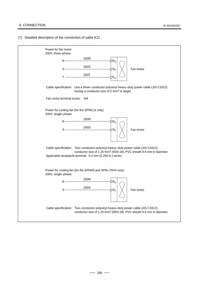
9. CONNECTION B–65162E/03
280
(7) Detailed description of the connection of cable K11
R
S
T
200R
200S
200T
R0
S0
T0
Fan motor
Power for fan motor200V, three–phase
Cable specification: Use a three–conductor polyvinyl heavy–duty power cable (JIS C3312) having a conductor size of 2 mm2 or larger.
Fan motor terminal screw: M4
R
S
200R
200S
R0
S0 Fan motor
Power for cooling fan (for the SPMC11 only)200V, single–phase
Cable specification: Two–conductor polyvinyl heavy–duty power cable (JIS C3312), conductor size of 1.25 mm2 (50/0.18), PVC sheath 9.6 mm in diameter
Applicable receptacle terminal: 6.3 mm (0.250 in.) series
R
S
200R
200S
R0
S0 Fan motor
Power for cooling fan (for the SPM45 and SPM–75HV only)200V, single–phase
Cable specification: Two–conductor polyvinyl heavy–duty power cable (JIS C3312), conductor size of 1.25 mm2 (50/0.18), PVC sheath 9.6 mm in diameter
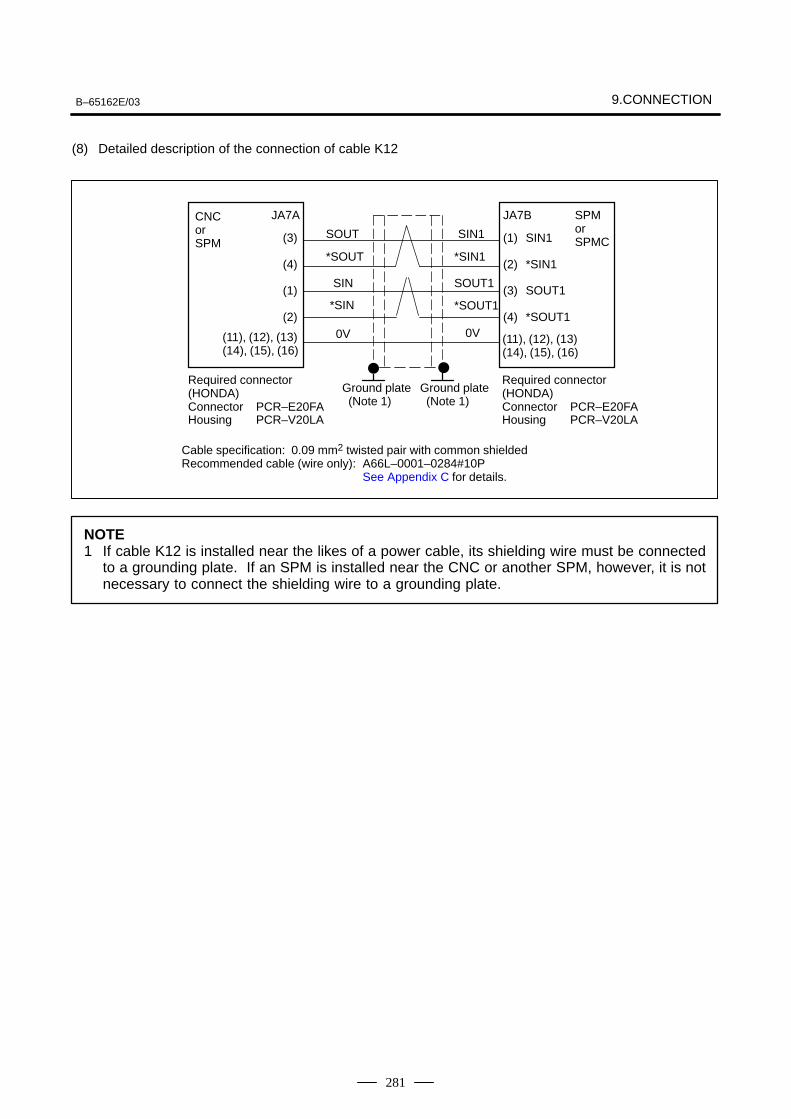
B–65162E/03 9.CONNECTION
281
(8) Detailed description of the connection of cable K12
Cable specification: 0.09 mm2 twisted pair with common shieldedRecommended cable (wire only): A66L–0001–0284#10P
See Appendix C for details.
Required connector (HONDA)Connector PCR–E20FAHousing PCR–V20LA
Required connector (HONDA)Connector PCR–E20FAHousing PCR–V20LA
CNCor SPM
JA7A
(3)
(4)
(1)
(2)
(11), (12), (13)(14), (15), (16)
(1)
(2)
(3)
(4)
JA7B SPM or SPMCSIN1
*SIN1
SOUT1
*SOUT1
(11), (12), (13)(14), (15), (16)
SIN1
*SIN1
SOUT1
*SOUT1
SOUT
*SOUT
SIN
*SIN
0V0V
Ground plate (Note 1)
Ground plate (Note 1)
NOTE1 If cable K12 is installed near the likes of a power cable, its shielding wire must be connected
to a grounding plate. If an SPM is installed near the CNC or another SPM, however, it is notnecessary to connect the shielding wire to a grounding plate.
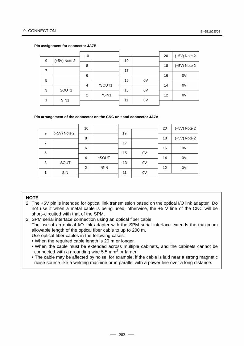
9. CONNECTION B–65162E/03
282
10 20 (+5V) Note 29 (+5V) Note 2 19
8 18 (+5V) Note 27 17
6 16 0V5 15 0V
4 *SOUT1 14 0V3 SOUT1 13 0V
2 *SIN1 12 0V1 SIN1 11 0V
Pin assignment for connector JA7B
Pin arrangement of the connector on the CNC unit and connector JA7A
10 20 (+5V) Note 29 (+5V) Note 2 19
8 18 (+5V) Note 27 17
6 16 0V5 15 0V
4 *SOUT 14 0V3 SOUT 13 0V
2 *SIN 12 0V1 SIN 11 0V
NOTE2 The +5V pin is intended for optical link transmission based on the optical I/O link adapter. Do
not use it when a metal cable is being used; otherwise, the +5 V line of the CNC will beshort–circuited with that of the SPM.
3 SPM serial interface connection using an optical fiber cableThe use of an optical I/O link adapter with the SPM serial interface extends the maximumallowable length of the optical fiber cable to up to 200 m.Use optical fiber cables in the following cases: When the required cable length is 20 m or longer. When the cable must be extended across multiple cabinets, and the cabinets cannot be
connected with a grounding wire 5.5 mm2 or larger. The cable may be affected by noise, for example, if the cable is laid near a strong magnetic
noise source like a welding machine or in parallel with a power line over a long distance.
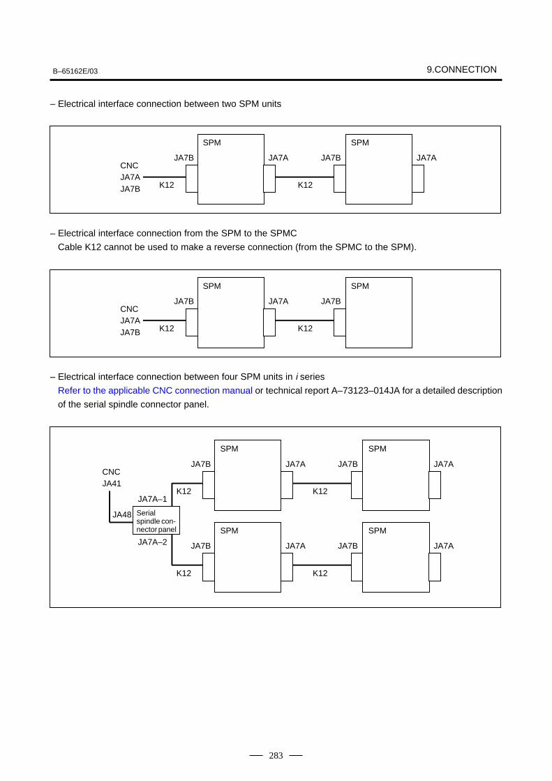
B–65162E/03 9.CONNECTION
283
– Electrical interface connection between two SPM units
SPM
CNCJA7AJA7B
JA7B
K12 K12
JA7AJA7A
SPM
JA7B
– Electrical interface connection from the SPM to the SPMC
Cable K12 cannot be used to make a reverse connection (from the SPMC to the SPM).
SPM
CNCJA7AJA7B
JA7B
K12 K12
JA7A
SPM
JA7B
– Electrical interface connection between four SPM units in i series
Refer to the applicable CNC connection manual or technical report A–73123–014JA for a detailed description
of the serial spindle connector panel.
SPM
CNCJA41
JA48
JA7A–2
JA7A–1K12
K12K12
K12
JA7B JA7A
SPM
JA7B
SPM
JA7B JA7A
SPM
JA7B
JA7A
JA7A
Serialspindle con-nector panel
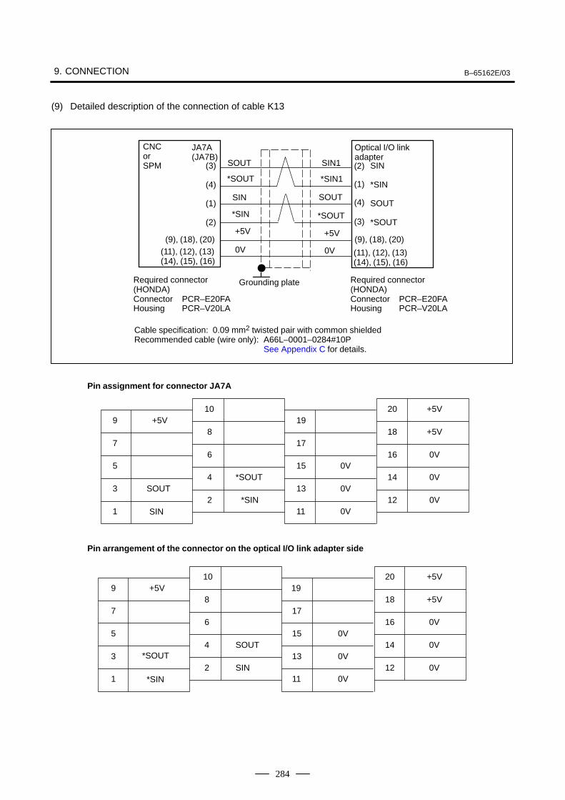
9. CONNECTION B–65162E/03
284
(9) Detailed description of the connection of cable K13
Cable specification: 0.09 mm2 twisted pair with common shieldedRecommended cable (wire only): A66L–0001–0284#10P
See Appendix C for details.
Required connector (HONDA)Connector PCR–E20FAHousing PCR–V20LA
Required connector (HONDA)Connector PCR–E20FAHousing PCR–V20LA
CNC or SPM
JA7A(JA7B)
(3)
(4)
(1)
(2)
(11), (12), (13)(14), (15), (16)
(1)
(2)
(3)
(4)
SIN
*SIN
SOUT
*SOUT
(11), (12), (13)(14), (15), (16)
SIN1
*SIN1
SOUT
*SOUT
SOUT
*SOUT
SIN
*SIN
0V0V
Grounding plate
+5V +5V
Optical I/O link adapter
(9), (18), (20)(9), (18), (20)
10 20 +5V9 +5V 19
8 18 +5V7 17
6 16 0V5 15 0V
4 *SOUT 14 0V3 SOUT 13 0V
2 *SIN 12 0V1 SIN 11 0V
Pin assignment for connector JA7A
10 20 +5V9 +5V 19
8 18 +5V7 17
6 16 0V5 15 0V
4 SOUT 14 0V3 *SOUT 13 0V
2 SIN 12 0V1 *SIN 11 0V
Pin arrangement of the connector on the optical I/O link adapter side
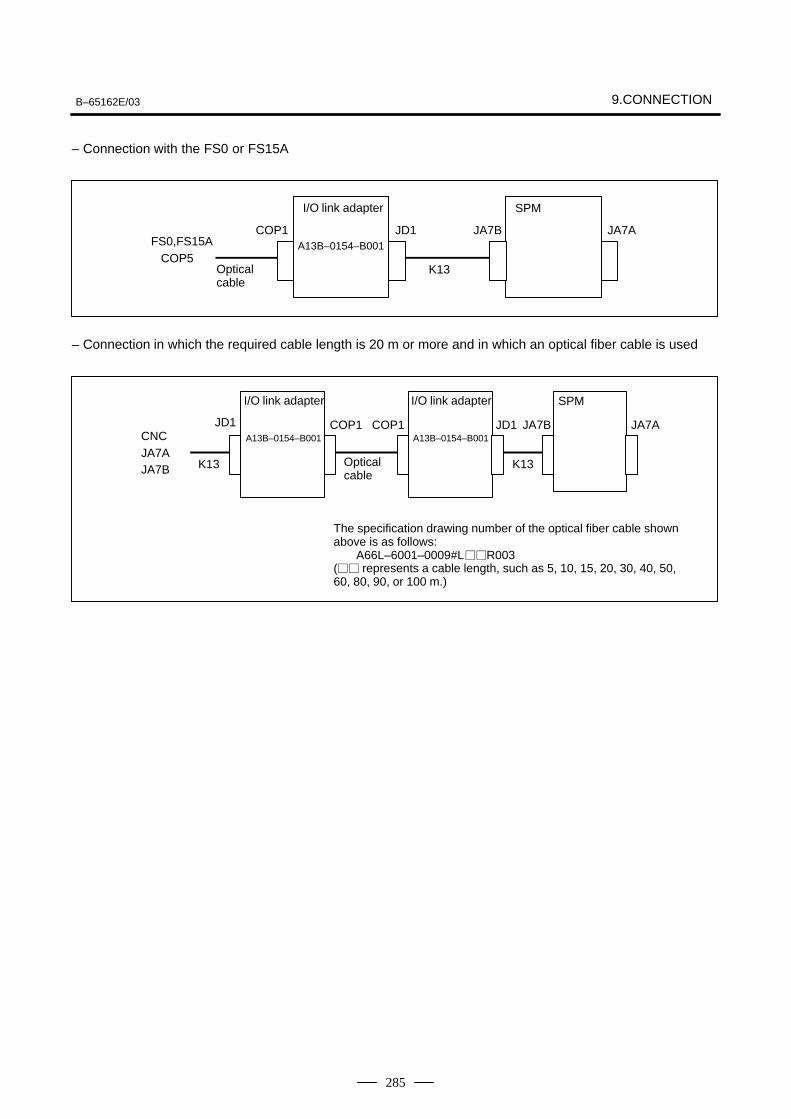
B–65162E/03 9.CONNECTION
285
– Connection with the FS0 or FS15A
I/O link adapter
A13B–0154–B001FS0,FS15ACOP5
COP1
Opticalcable
K13
JA7AJD1
SPM
JA7B
– Connection in which the required cable length is 20 m or more and in which an optical fiber cable is used
CNCJA7AJA7B K13
COP1
I/O link adapter
A13B–0154–B001
Opticalcable
SPMI/O link adapter
A13B–0154–B001COP1
K13
JD1 JA7B JA7A
The specification drawing number of the optical fiber cable shownabove is as follows:
A66L–6001–0009#LR003( represents a cable length, such as 5, 10, 15, 20, 30, 40, 50,60, 80, 90, or 100 m.)
JD1
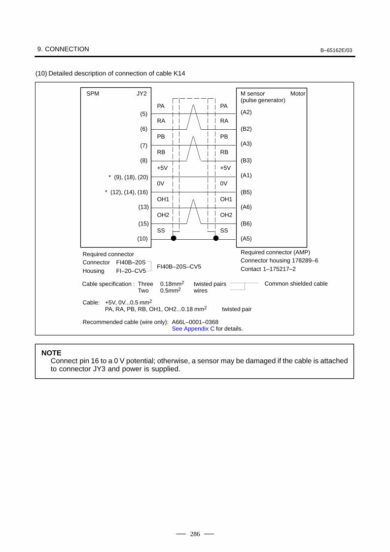
9. CONNECTION B–65162E/03
286
(10) Detailed description of connection of cable K14
Recommended cable (wire only): A66L–0001–0368See Appendix C for details.
Cable: +5V, 0V...0.5 mm2
PA, RA, PB, RB, OH1, OH2...0.18 mm2 twisted pair
PA
RA
PB
RB
+5V
0V
OH1
OH2
SS
(A2)
(B2)
(A3)
(B3)
(A1)
(B5)
(A6)
(B6)
(A5)
SPM JY2
(5)
(6)
(7)
(8)
(9), (18), (20)
(12), (14), (16)
(13)
(15)
(10)
*
*
Required connectorConnector FI40B–20SHousing FI–20–CV5
Required connector (AMP)Connector housing 178289–6Contact 1–175217–2FI40B–20S–CV5
Cable specification : Three 0.18mm2 twisted pairsTwo 0.5mm2 wires
PA
RA
PB
RB
+5V
0V
OH1
OH2
SS
M sensor (pulse generator)
Motor
Common shielded cable
NOTEConnect pin 16 to a 0 V potential; otherwise, a sensor may be damaged if the cable is attachedto connector JY3 and power is supplied.
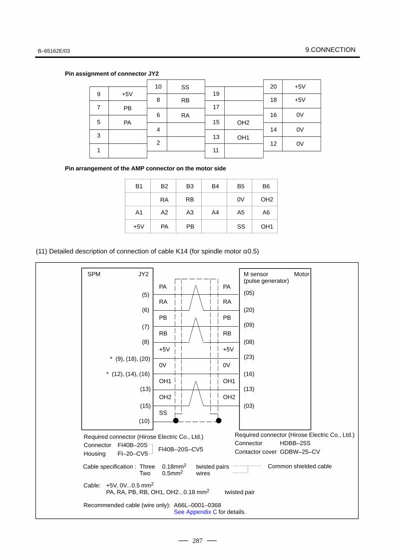
B–65162E/03 9.CONNECTION
287
10 20 +5V9 +5V 19
8 18 +5V7 17
6 16 0V5 15
4 14 0V3 13
2 12 0V1 11
Pin assignment of connector JY2
Pin arrangement of the AMP connector on the motor side
PB
PA
SS
RB
RAOH2
OH1
B1 B2 B3 B4 B5 B6
RA RB 0V OH2
A1 A2 A3 A4 A5 A6
+5V PA PB SS OH1
(11) Detailed description of connection of cable K14 (for spindle motor α0.5)
Recommended cable (wire only): A66L–0001–0368See Appendix C for details.
Cable: +5V, 0V...0.5 mm2
PA, RA, PB, RB, OH1, OH2...0.18 mm2 twisted pair
Cable specification : Three 0.18mm2 twisted pairsTwo 0.5mm2 wires
Common shielded cable
PA
RA
PB
RB
+5V
0V
OH1
OH2
SS
(05)
(20)
(09)
(08)
(23)
(16)
(13)
(03)
SPM JY2
(5)
(6)
(7)
(8)
(9), (18), (20)
(12), (14), (16)
(13)
(15)
(10)
*
*
Required connector (Hirose Electric Co., Ltd.)Connector FI40B–20SHousing FI–20–CV5
Required connector (Hirose Electric Co., Ltd.)Connector HDBB–25SContactor cover GDBW–25–CVFI40B–20S–CV5
PA
RA
PB
RB
+5V
0V
OH1
OH2
M sensor (pulse generator)
Motor
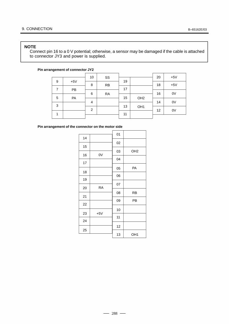
9. CONNECTION B–65162E/03
288
NOTEConnect pin 16 to a 0 V potential; otherwise, a sensor may be damaged if the cable is attachedto connector JY3 and power is supplied.
10 20 +5V9 +5V 19
8 18 +5V7 17
6 16 0V5 15
4 14 0V3 13
2 12 0V1 11
Pin arrangement of connector JY2
PB
PA
SS
RB
RAOH2
OH1
Pin arrangement of the connector on the motor side
14
15
16
17
18
0V
19
20
21
22
23
RA
24
25
+5V
01
02
03
04
05
OH2
06
07
08
09
10
PA
11
12
PB
13
RB
OH1
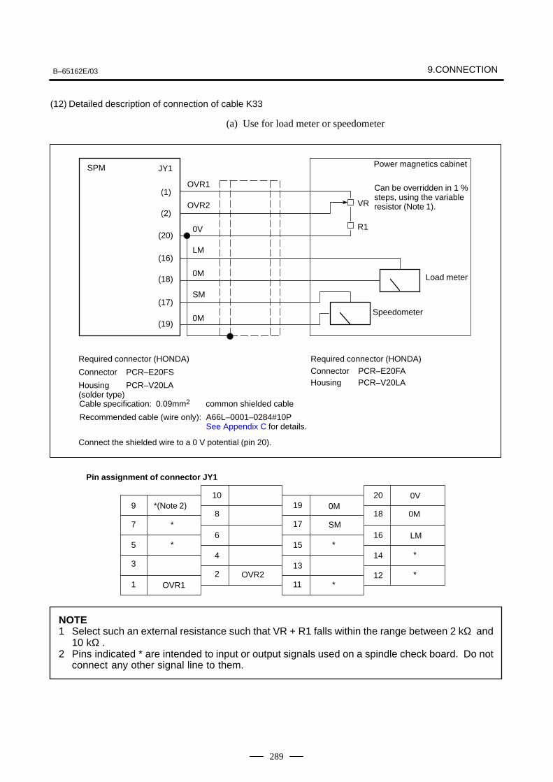
B–65162E/03 9.CONNECTION
289
(12) Detailed description of connection of cable K33
(a) Use for load meter or speedometer
Required connector (HONDA)
Connector PCR–E20FS
Housing PCR–V20LA(solder type)
Recommended cable (wire only): A66L–0001–0284#10PSee Appendix C for details.
10 209 19
8 187 17
6 165 15
4 143 13
2 121 11
Pin assignment of connector JY1
SPM JY1
(1)
(2)
(20)
(16)
(18)
(17)
(19)
OVR1
OVR2
0V
LM
0M
SM
0M
VR
R1
Power magnetics cabinet
Can be overridden in 1 % steps, using the variable resistor (Note 1).
Load meter
Speedometer
Connector PCR–E20FAHousing PCR–V20LA
Cable specification: 0.09mm2 common shielded cable
OVR1OVR2
0MSM
0V0M
LM
Required connector (HONDA)
Connect the shielded wire to a 0 V potential (pin 20).
*(Note 2)
*
*
*
*
*
*
NOTE1 Select such an external resistance such that VR + R1 falls within the range between 2 kΩ and
10 kΩ .2 Pins indicated * are intended to input or output signals used on a spindle check board. Do not
connect any other signal line to them.
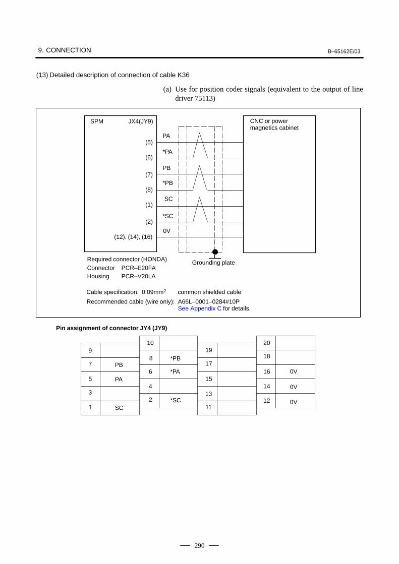
9. CONNECTION B–65162E/03
290
(13) Detailed description of connection of cable K36
(a) Use for position coder signals (equivalent to the output of linedriver 75113)
Recommended cable (wire only): A66L–0001–0284#10PSee Appendix C for details.
Cable specification: 0.09mm2 common shielded cable
Connector PCR–E20FAHousing PCR–V20LA
Required connector (HONDA)
PA
*PA
PB
*PB
SPM JX4(JY9)
(5)
(6)
(7)
(8)
(12), (14), (16)
SC
*SC
(1)
(2)
CNC or powermagnetics cabinet
Grounding plate
10 209 19
8 187 17
6 16 0V5 15
4 143 13
2 121 11
Pin assignment of connector JY4 (JY9)
0V
PB
PA
SC
*PB
*PA
*SC
0V
0V
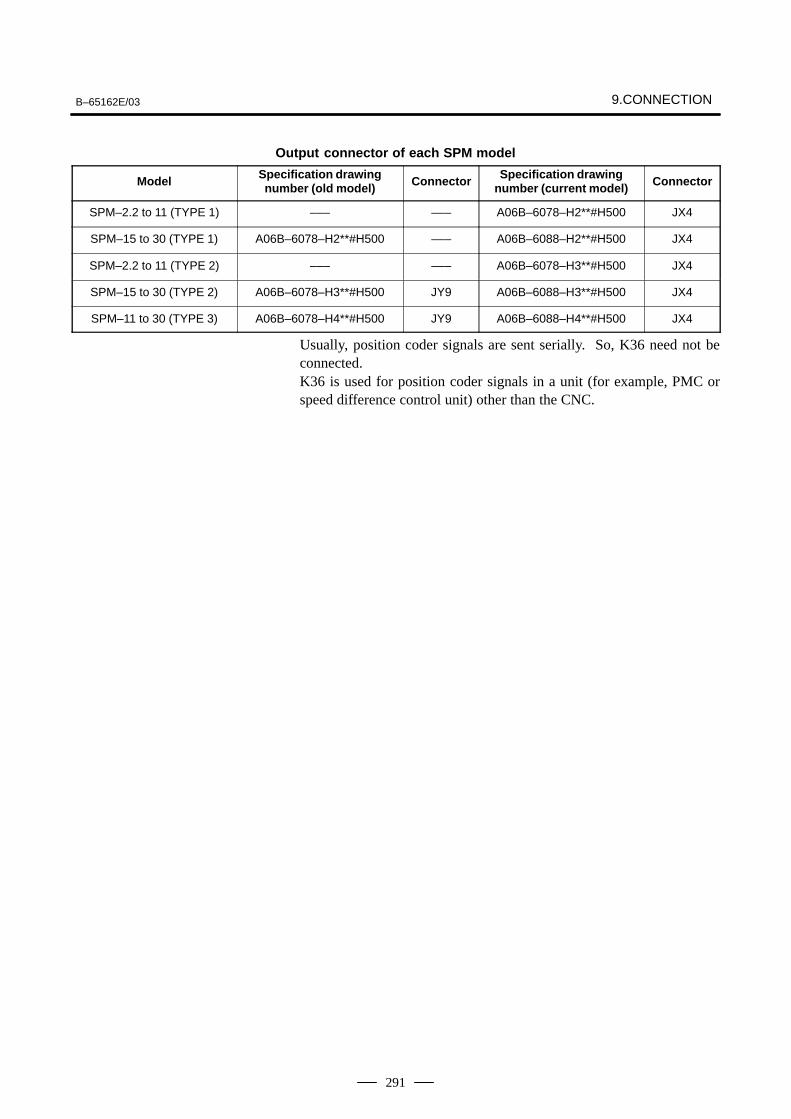
B–65162E/03 9.CONNECTION
291
Output connector of each SPM model
Model Specification drawingnumber (old model) Connector Specification drawing
number (current model) Connector
SPM–2.2 to 11 (TYPE 1) ––– ––– A06B–6078–H2**#H500 JX4
SPM–15 to 30 (TYPE 1) A06B–6078–H2**#H500 ––– A06B–6088–H2**#H500 JX4
SPM–2.2 to 11 (TYPE 2) ––– ––– A06B–6078–H3**#H500 JX4
SPM–15 to 30 (TYPE 2) A06B–6078–H3**#H500 JY9 A06B–6088–H3**#H500 JX4
SPM–11 to 30 (TYPE 3) A06B–6078–H4**#H500 JY9 A06B–6088–H4**#H500 JX4
Usually, position coder signals are sent serially. So, K36 need not beconnected.K36 is used for position coder signals in a unit (for example, PMC orspeed difference control unit) other than the CNC.
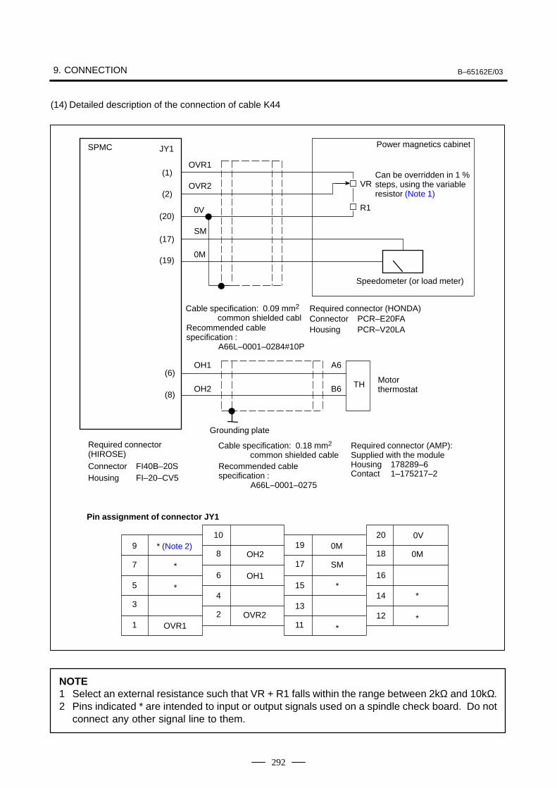
9. CONNECTION B–65162E/03
292
(14) Detailed description of the connection of cable K44
Required connector (AMP): Supplied with the moduleHousing 178289–6Contact 1–175217–2
Required connector (HIROSE)Connector FI40B–20SHousing FI–20–CV5
Recommended cable specification :
A66L–0001–0275
10 209 19
8 187 17
6 165 15
4 143 13
2 121 11
Pin assignment of connector JY1
SPMC JY1
(1)
(2)
(20)
(17)
(19)
(6)
(8)
OVR1
OVR2
0V
SM
0M
OH1
OH2
VR
R1
Power magnetics cabinet
Can be overridden in 1 %steps, using the variableresistor (Note 1)
Cable specification: 0.18 mm2 common shielded cable
OVR1OVR2
0MSM
0V0M
*
Grounding plate
A6
B6 TH
Speedometer (or load meter)
Cable specification: 0.09 mm2 common shielded cabl
Recommended cable specification :
A66L–0001–0284#10P
Connector PCR–E20FAHousing PCR–V20LA
Required connector (HONDA)
Motor thermostat
* (Note 2)
*
*
OH2
OH1*
**
NOTE1 Select an external resistance such that VR + R1 falls within the range between 2kΩ and 10kΩ.2 Pins indicated * are intended to input or output signals used on a spindle check board. Do not
connect any other signal line to them.
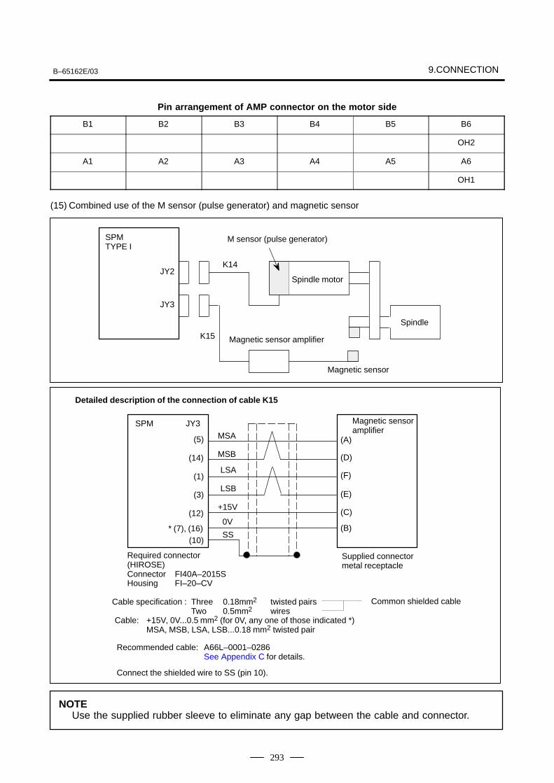
B–65162E/03 9.CONNECTION
293
Pin arrangement of AMP connector on the motor side
B1 B2 B3 B4 B5 B6
OH2
A1 A2 A3 A4 A5 A6
OH1
(15) Combined use of the M sensor (pulse generator) and magnetic sensor
SPMTYPE I
JY2
JY3
K14
K15
M sensor (pulse generator)
Spindle motor
Magnetic sensor amplifier
Spindle
Magnetic sensor
Cable specification : Three 0.18mm2 twisted pairsTwo 0.5mm2 wires
Common shielded cable
Required connector (HIROSE)Connector FI40A–2015SHousing FI–20–CV
Detailed description of the connection of cable K15
JY3
(5)
(14)
(1)
(3)
(12)
(D)
(A)
(E)
(F)
0V* (7), (16)
(C)
(B)
MSA
MSB
LSA
LSB
+15V
Recommended cable: A66L–0001–0286See Appendix C for details.
Cable: +15V, 0V...0.5 mm2 (for 0V, any one of those indicated *)MSA, MSB, LSA, LSB...0.18 mm2 twisted pair
Magnetic sensor amplifier
(10)
SPM
Connect the shielded wire to SS (pin 10).
SS
Supplied connector metal receptacle
NOTEUse the supplied rubber sleeve to eliminate any gap between the cable and connector.
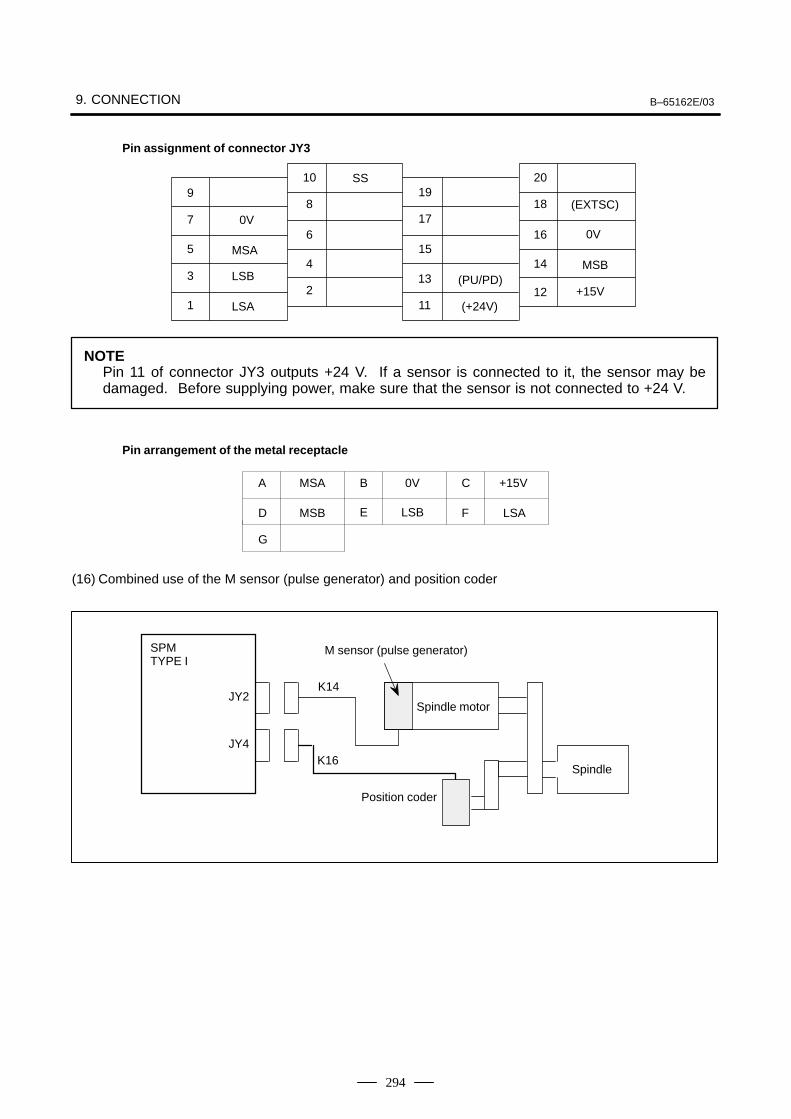
9. CONNECTION B–65162E/03
294
10 209 19
8 18
+15V
7 176 16 0V
5 154 14
3 132 12
1 11
Pin assignment of connector JY3
0V
MSA
LSB
LSA
(PU/PD)
(+24V)
MSB
(EXTSC)
SS
NOTEPin 11 of connector JY3 outputs +24 V. If a sensor is connected to it, the sensor may bedamaged. Before supplying power, make sure that the sensor is not connected to +24 V.
Pin arrangement of the metal receptacle
0VA
D
G
B
E
C
FLSB
+15V
LSA
MSA
MSB
(16) Combined use of the M sensor (pulse generator) and position coder
SPMTYPE I
JY2
JY4
K14
K16
M sensor (pulse generator)
Spindle motor
Spindle
Position coder
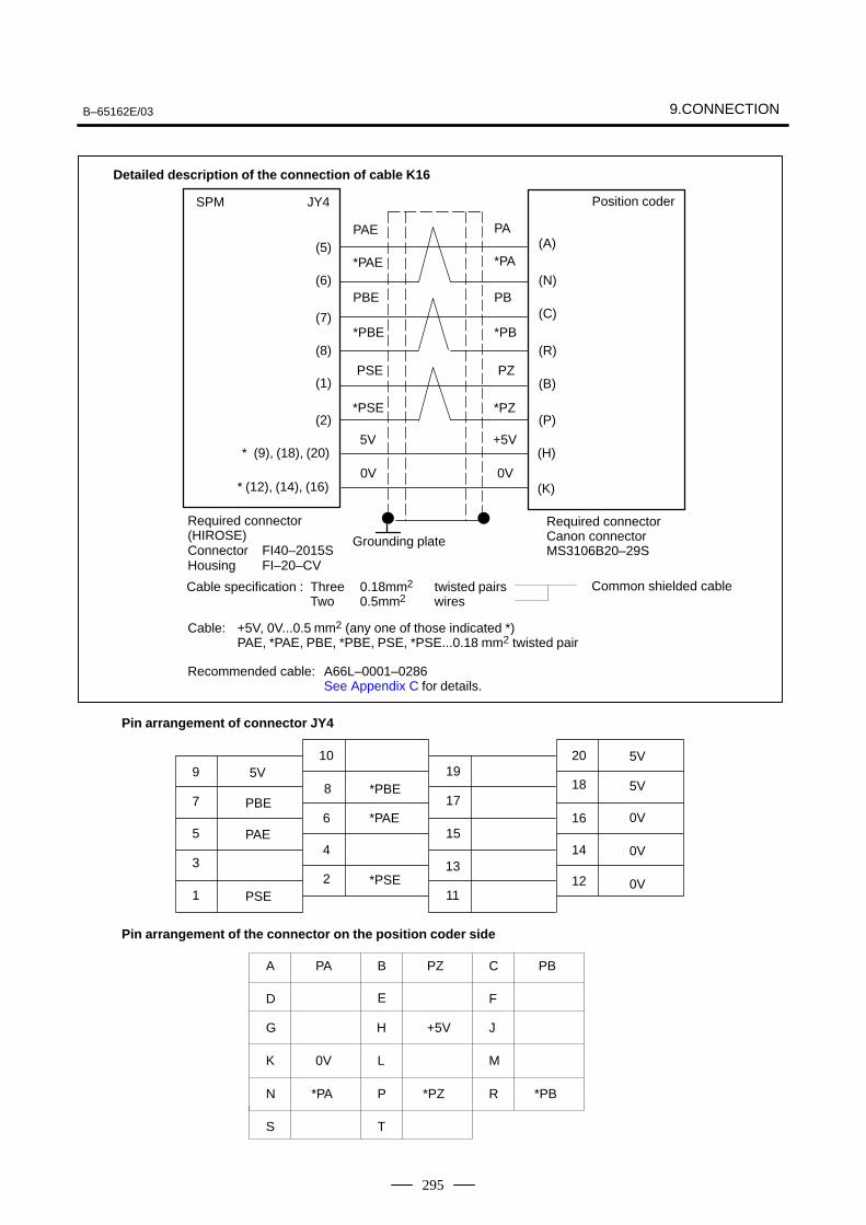
B–65162E/03 9.CONNECTION
295
Cable specification : Three 0.18mm2 twisted pairsTwo 0.5mm2 wires
Common shielded cable
PAE
*PAE
PBE
*PBE
5V
0V
(A)
(N)
(C)
(R)
(B)
(P)
SPM JY4
(5)
(6)
(7)
(8)
(9), (18), (20)
* (12), (14), (16)
*
Required connector (HIROSE)Connector FI40–2015SHousing FI–20–CV
Cable: +5V, 0V...0.5 mm2 (any one of those indicated *)PAE, *PAE, PBE, *PBE, PSE, *PSE...0.18 mm2 twisted pair
Recommended cable: A66L–0001–0286See Appendix C for details.
PSE
*PSE
(H)
(K)
(1)
(2)
Position coder
Grounding plate
Required connectorCanon connector MS3106B20–29S
10 209 19
8 187 17
6 16 0V5 15
4 143 13
2 121 11
Pin arrangement of connector JY4
Pin arrangement of the connector on the position coder side
0V
A
D
G
B
E
C
F
5V
PBE
PAE
PSE
*PBE
*PAE
*PSE
5V
5V
0V
K
N
S
H
L
P
T
PA
0V
*PA
PZ
+5V
*PZ
PB
*PB
J
M
R
Detailed description of the connection of cable K16
PA
*PA
PB
*PB
+5V
0V
PZ
*PZ
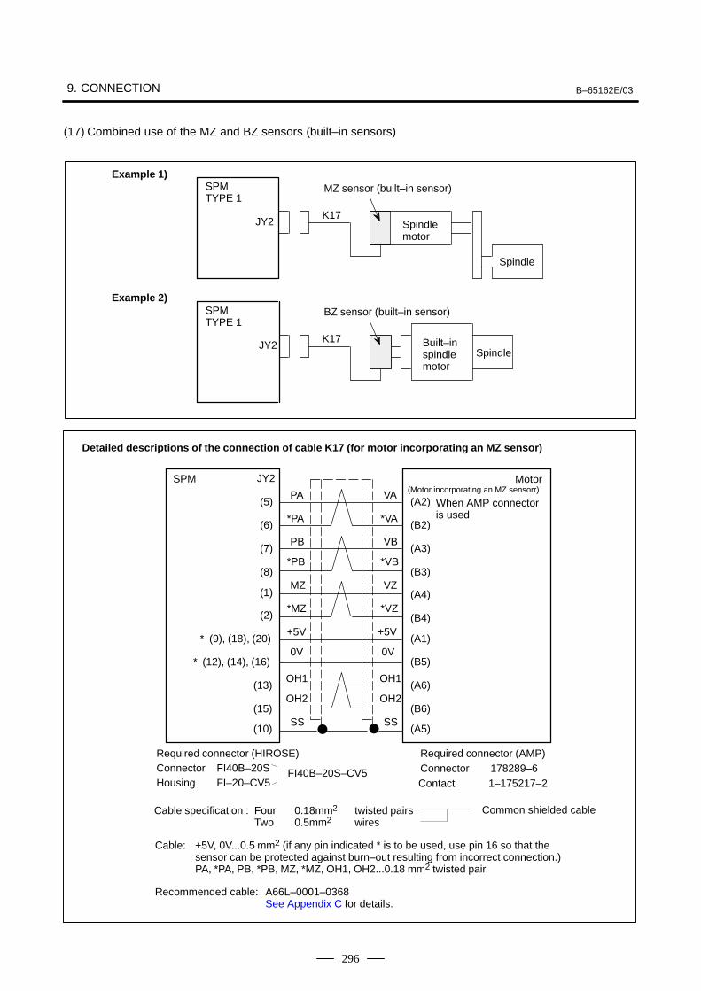
9. CONNECTION B–65162E/03
296
(17) Combined use of the MZ and BZ sensors (built–in sensors)
SPMTYPE 1
SPMTYPE 1
JY2
JY2
K17
K17
Spindle
Spindlemotor
Spindle
Built–inspindlemotor
BZ sensor (built–in sensor)
MZ sensor (built–in sensor)Example 1)
Example 2)
Cable specification : Four 0.18mm2 twisted pairsTwo 0.5mm2 wires
Common shielded cable
Detailed descriptions of the connection of cable K17 (for motor incorporating an MZ sensor)
SPM JY2
(5)
(6)
(7)
(8)
(1)
(2)
* (9), (18), (20)
* (12), (14), (16)
(13)
(15)
(10)
(A2)
(B2)
(A3)
(B3)
(A4)
(B4)
(A1)
(B5)
(A6)
(B6)
(A5)
(Motor incorporating an MZ sensorr)PA
*PA
PB
MZ
*MZ
+5V
0V
OH1
OH2
SS
*PB
OH1
OH2
SS
+5V
0V
VA
*VA
VB
*VB
VZ
*VZ
Required connector (HIROSE)Connector FI40B–20SHousing FI–20–CV5
Cable: +5V, 0V...0.5 mm2 (if any pin indicated * is to be used, use pin 16 so that the sensor can be protected against burn–out resulting from incorrect connection.)PA, *PA, PB, *PB, MZ, *MZ, OH1, OH2...0.18 mm2 twisted pair
Recommended cable: A66L–0001–0368See Appendix C for details.
Required connector (AMP)Connector 178289–6Contact 1–175217–2
FI40B–20S–CV5
Motor
When AMP connectoris used
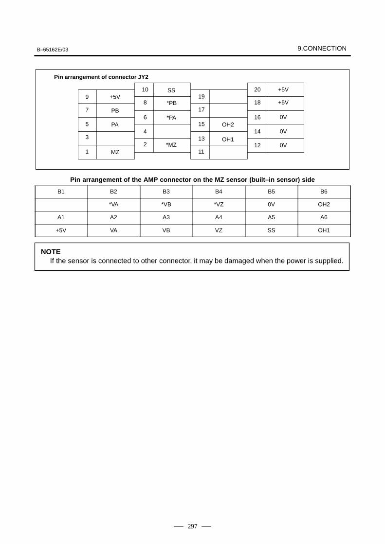
B–65162E/03 9.CONNECTION
297
10 20 +5V9 +5V 19
8 18 +5V7 17
6 16 0V5 15
4 14 0V3 13
2 12 0V1 11
Pin arrangement of connector JY2
PB
PA
SS
*PB
*PAOH2
OH1
MZ*MZ
Pin arrangement of the AMP connector on the MZ sensor (built–in sensor) side
B1 B2 B3 B4 B5 B6
*VA *VB *VZ 0V OH2
A1 A2 A3 A4 A5 A6
+5V VA VB VZ SS OH1
NOTEIf the sensor is connected to other connector, it may be damaged when the power is supplied.
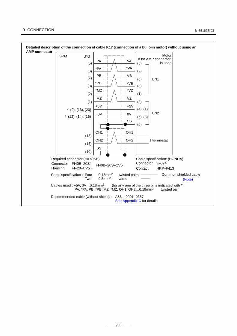
9. CONNECTION B–65162E/03
298
Cable specification : Four 0.18mm2 twisted pairsTwo 0.5mm2 wires
Common shielded cable
Detailed description of the connection of cable K17 (connection of a built–in motor) without using an AMP connector
SPM JY2
(5)
(6)
(7)
(8)
(2)
(1)
* (9), (18), (20)
* (12), (14), (16)
(13)
(15)
(10)
(5)
(6)
(2)
(3)
(1)
(2)
(4), (1)
(6), (3)
(5)
CN1
CN2
OH1
OH2
OH1
OH2
SS
SS
PA
*PA
PB
*PB
*MZ
MZ
+5V
0V
VA
VB
*VB
*VZ
VZ
+5V
0V
*VA
Thermostat
Motor
Required connector (HIROSE)Connector FI40B–20SHousing FI–20–CV5
Cables used : +5V, 0V…0.18mm2 (for any one of the three pins indicated with *)PA, *PA, PB, *PB, MZ, *MZ, OH1, OH2…0.18mm2 twisted pair
Recommended cable (without shield) : A66L–0001–0367See Appendix C for details.
Cable specification: (HONDA)Connector Z–374
FI40B–20S–CV5Contact HKP–F413
(Note)
If no AMP connector is used
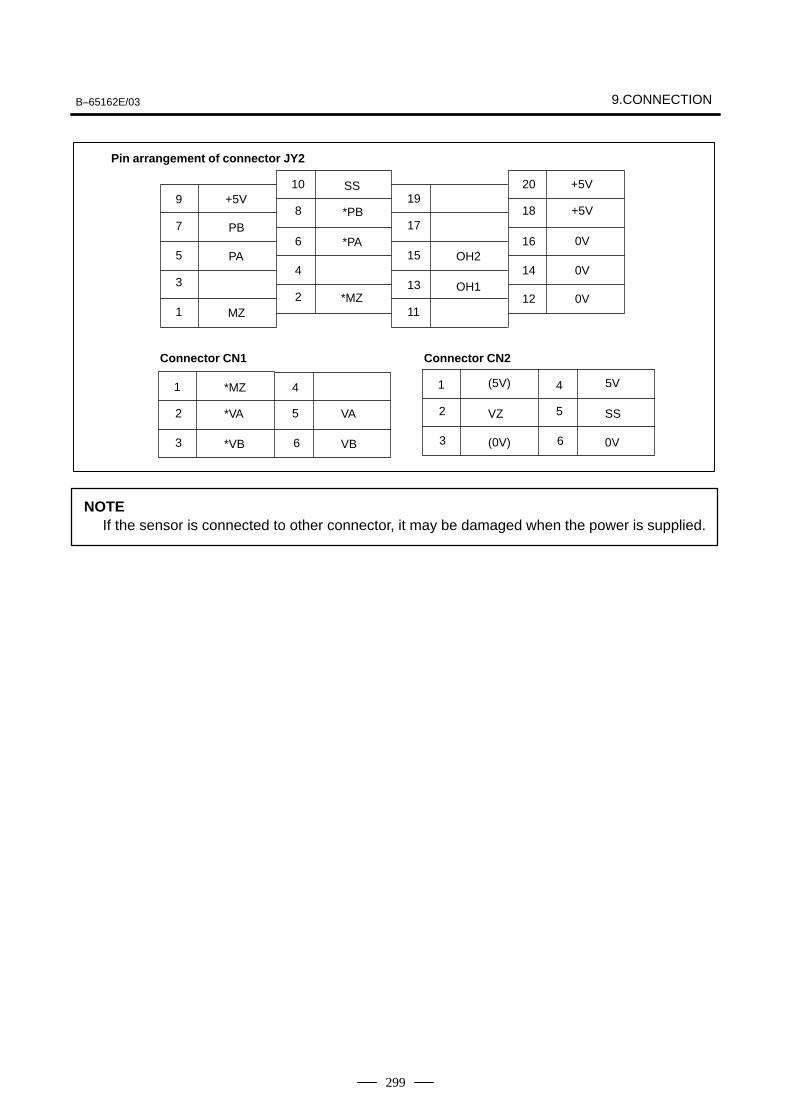
B–65162E/03 9.CONNECTION
299
10 20
5V
9 +5V 198 18 +5V
7 176 16 0V
5 154 14 0V
3 132 12 0V
1 11
Pin arrangement of connector JY2
PB
PA
SS
*PB
*PAOH2
OH1
MZ*MZ
6
5
3
2
1
VB
VA
*VB
*VA
4
SS
*MZ
6
5
3
2
1 4
VZ
+5V
0V
Connector CN1 Connector CN2
(5V)
(0V)
NOTEIf the sensor is connected to other connector, it may be damaged when the power is supplied.
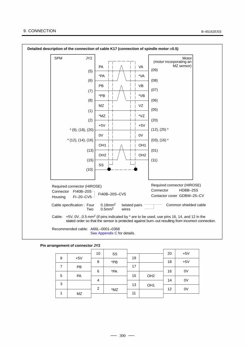
9. CONNECTION B–65162E/03
300
Cable: +5V, 0V...0.5 mm2 (if pins indicated by * are to be used, use pins 16, 14, and 12 in the stated order so that the sensor is protected against burn–out resulting from incorrect connection.
Cable specification : Four 0.18mm2 twisted pairsTwo 0.5mm2 wires
Common shielded cable
PA
*PA
PB
*PB
MZ
*MZ
+5V
SS
(09)
(08)
(07)
(06)
(05)
(20)
(12), (25) *
(03), (16) *
SPM JY2
(5)
(6)
(7)
(8)
(1)
(2)
(13)
(15)
(10)
Required connector (HIROSE)Connector FI40B–20S
Housing FI–20–CV5
Required connector (HIROSE)Connector HDBB–25S
Contactor cover GDBW–25–CVFI40B–20S–CV5
Recommended cable: A66L–0001–0368See Appendix C for details.
10 20 +5V9 +5V 19
8 18 +5V7 17
6 16 0V5 15
4 14 0V3 13
2 12 0V1 11
Pin arrangement of connector JY2
PB
PA
SS
*PB
*PAOH2
OH1
(motor incorporating anMZ sensor)
Motor
Detailed description of the connection of cable K17 (connection of spindle motor α0.5)
* (9), (18), (20)
* (12), (14), (16)0V
OH1
OH2
VA
*VA
VB
*VB
VZ
*VZ
+5V
0V
OH1
OH2(01)
(11)
MZ*MZ
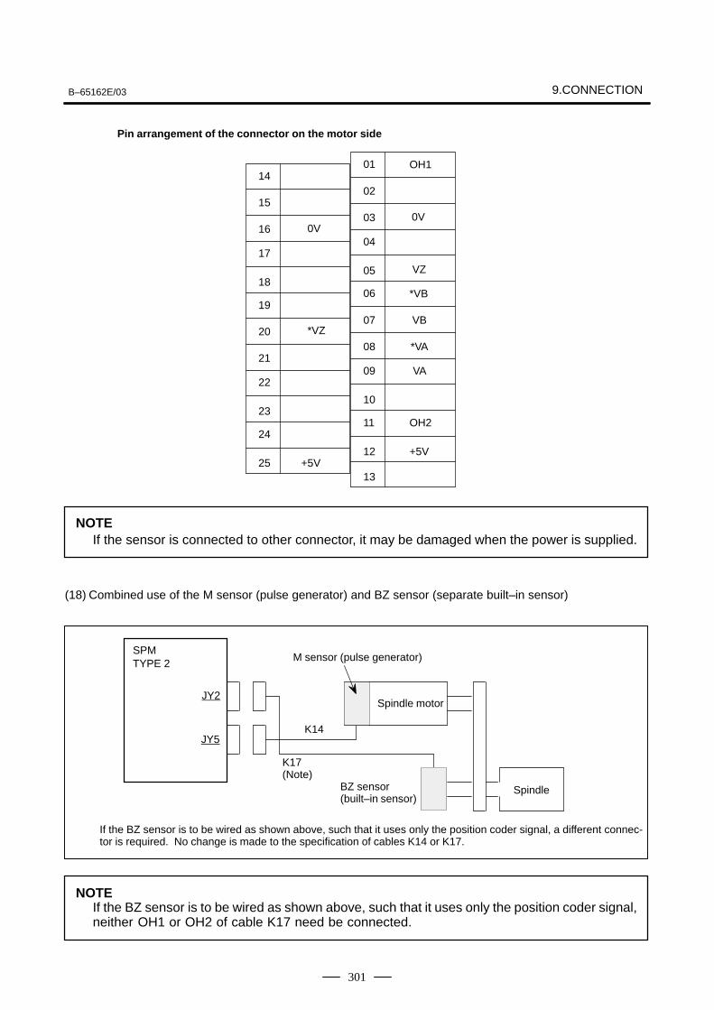
B–65162E/03 9.CONNECTION
301
Pin arrangement of the connector on the motor side
14
15
16
17
18
0V
19
20
21
22
23
*VZ
24
25 +5V
01
02
03
04
05
0V
06
07
08
09
10
VZ
11
12
VA
13
*VA
OH2
+5V
VB
*VB
OH1
NOTEIf the sensor is connected to other connector, it may be damaged when the power is supplied.
(18) Combined use of the M sensor (pulse generator) and BZ sensor (separate built–in sensor)
SPMTYPE 2
JY2
JY5K14
K17(Note)
BZ sensor (built–in sensor)
Spindle
M sensor (pulse generator)
Spindle motor
If the BZ sensor is to be wired as shown above, such that it uses only the position coder signal, a different connec-tor is required. No change is made to the specification of cables K14 or K17.
NOTEIf the BZ sensor is to be wired as shown above, such that it uses only the position coder signal,neither OH1 or OH2 of cable K17 need be connected.
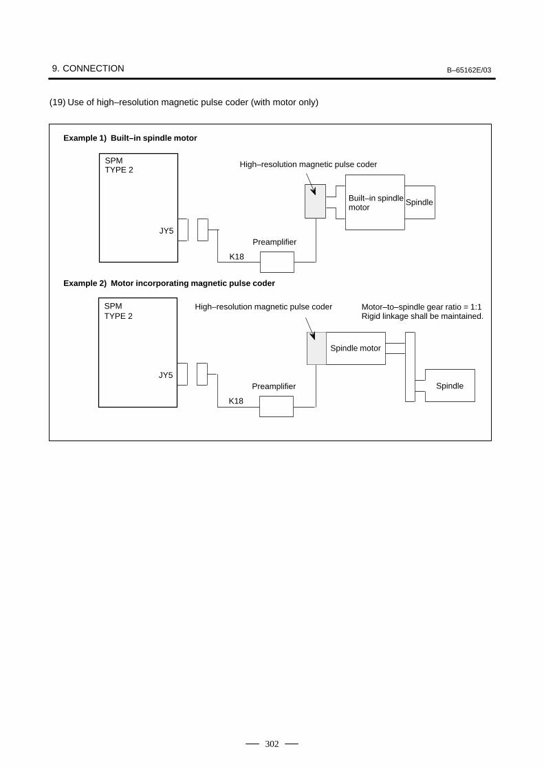
9. CONNECTION B–65162E/03
302
(19) Use of high–resolution magnetic pulse coder (with motor only)
Example 1) Built–in spindle motor
SPMTYPE 2
JY5
K18
Spindle
High–resolution magnetic pulse coder
Preamplifier
Built–in spindlemotor
Example 2) Motor incorporating magnetic pulse coder
SPMTYPE 2
JY5
K18
High–resolution magnetic pulse coder
Preamplifier
Motor–to–spindle gear ratio = 1:1Rigid linkage shall be maintained.
Spindle
Spindle motor
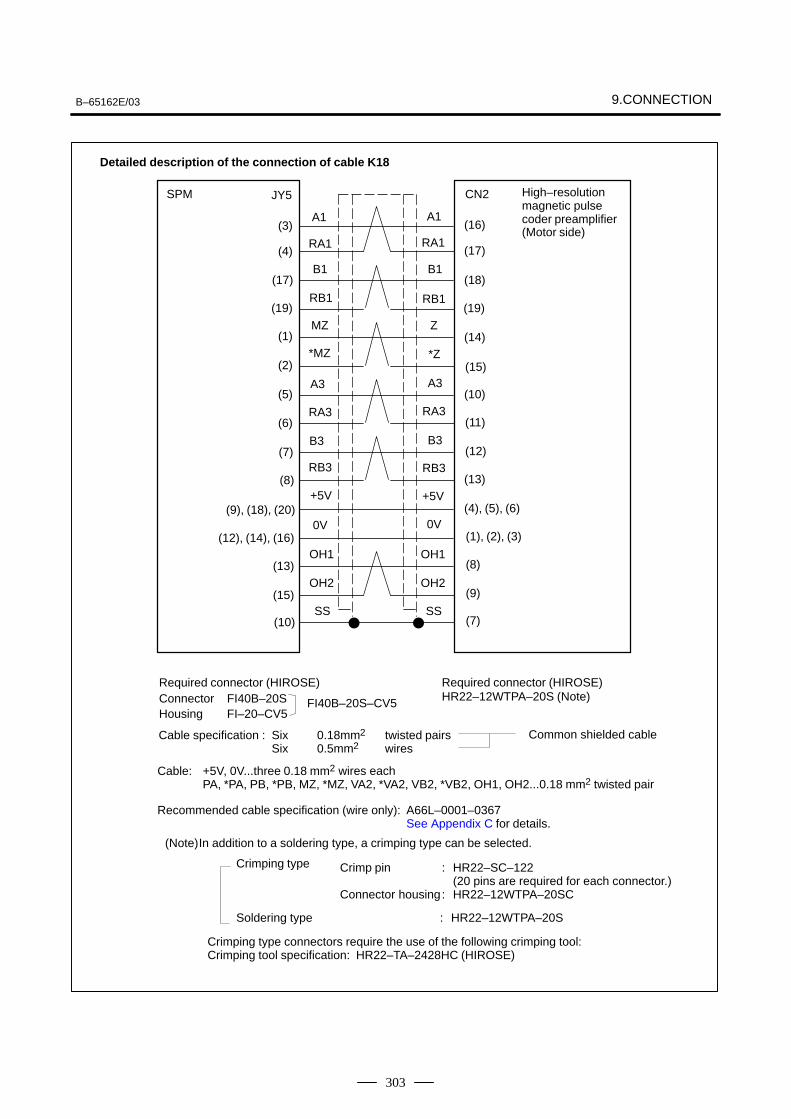
B–65162E/03 9.CONNECTION
303
Cable specification : Six 0.18mm2 twisted pairsSix 0.5mm2 wires
Common shielded cable
Detailed description of the connection of cable K18
SPM JY5
(3)
(4)
(17)
(19)
(1)
(2)
(5)
(6)
(7)
(8)
(9), (18), (20)
(12), (14), (16)
(13)
(15)
(10)
A1
RA1
B1
RB1
MZ
*MZ
A3
RA3
B3
RB3
+5V
0V
OH1
OH2
SS
A1
RA1
B1
RB1
Z
*Z
A3
RA3
B3
RB3
+5V
0V
OH1
OH2
SS
CN2
(16)
(17)
(18)
(19)
(14)
(15)
(10)
(11)
(12)
(13)
(4), (5), (6)
(1), (2), (3)
(8)
(9)
(7)
High–resolutionmagnetic pulsecoder preamplifier(Motor side)
Required connector (HIROSE)Connector FI40B–20SHousing FI–20–CV5
Cable: +5V, 0V...three 0.18 mm2 wires eachPA, *PA, PB, *PB, MZ, *MZ, VA2, *VA2, VB2, *VB2, OH1, OH2...0.18 mm2 twisted pair
Recommended cable specification (wire only): A66L–0001–0367See Appendix C for details.
Required connector (HIROSE)HR22–12WTPA–20S (Note)FI40B–20S–CV5
(Note)In addition to a soldering type, a crimping type can be selected.
Crimping type Crimp pin : HR22–SC–122(20 pins are required for each connector.)
Connector housing: HR22–12WTPA–20SC
Soldering type : HR22–12WTPA–20S
Crimping type connectors require the use of the following crimping tool:Crimping tool specification: HR22–TA–2428HC (HIROSE)
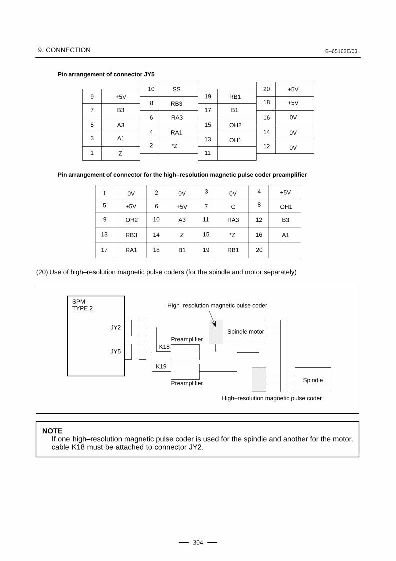
9. CONNECTION B–65162E/03
304
10 209 19
8 187 17
6 16 0V5 15
4 143 13
2 121 11
Pin arrangement of connector JY5
Pin arrangement of connector for the high–resolution magnetic pulse coder preamplifier
0V
+5V
B3
A3
RB3
RA3
+5V
+5V
0V
0V
+5V
A1
Z
SS
RA1
*Z
RB1
B1
OH2
OH1
OH2
RB3
RA1
0V
+5V
0V +5V1
5
9
13
17
2
6
10
14
18
3
7
11
15
19
A3
Z
B1
G
RA3
*Z
RB1
4
8
12
16
20
OH1
B3
A1
(20) Use of high–resolution magnetic pulse coders (for the spindle and motor separately)
SPMTYPE 2
JY2
Spindle
Spindle motor
JY5K18
K19
High–resolution magnetic pulse coder
Preamplifier
Preamplifier
High–resolution magnetic pulse coder
NOTEIf one high–resolution magnetic pulse coder is used for the spindle and another for the motor,cable K18 must be attached to connector JY2.

B–65162E/03 9.CONNECTION
305
High–resolutionmagnetic pulsecoder preamplifier(Motor side)
Detailed description of the connection of cable K18
SPM JY2
(3)
(4)
(17)
(19)
(1)
(2)
(5)
(6)
(7)
(8)
(9), (18), (20)
(12), (14), (16)
(13)
(15)
(10)
VA2
*VA2
VB2
*VB2
MZ
*MZ
PA
*PA
PB
*PB
+5V
0V
OH1
OH2
SS
A1
RA1
B1
RB1
Z
*Z
A3
RA3
B3
RB3
+5V
0V
OH1
OH2
SS
CN2
(16)
(17)
(18)
(19)
(14)
(15)
(10)
(11)
(12)
(13)
(4), (5), (6)
(1), (2), (3)
(8)
(9)
(7)
Cable specification : Six 0.18mm2 twisted pairsSix 0.5mm2 wires
Common shielded cable
Required connector (HIROSE)Connector FI40B–20SHousing FI–20–CV5
Cable: +5V, 0V...three 0.18 mm2 wires eachPA, *PA, PB, *PB, MZ, *MZ, VA2, *VA2, VB2, *VB2, OH1, OH2...0.18 mm2 twisted pair
Recommended cable specification (wire only): A66L–0001–0367See Appendix C for details.
Required connector (HIROSE)HR22–12WTPA–20S (Note)FI40B–20S–CV5
(Note)In addition to a soldering type, a crimping type can be selected.
Crimping type Crimp pin : HR22–SC–122(20 pins are required for each connector.)
Connector housing: HR22–12WTPA–20SC
Soldering type : HR22–12WTPA–20S
Crimping type connectors require the use of the following crimping tool:Crimping tool specification: HR22–TA–2428HC (HIROSE)
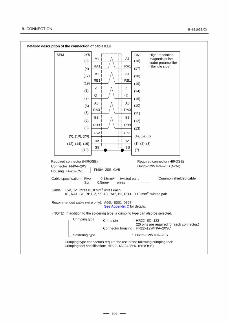
9. CONNECTION B–65162E/03
306
Cable specification : Five 0.18mm2 twisted pairsSix 0.5mm2 wires
Common shielded cable
Detailed description of the connection of cable K19
SPM JY5
(5)
(6)
(7)
(8)
(1), (2), (3)
(9), (18), (20)
(12), (14), (16)
(10)
(16)
(17)
(18)
(19)
(14)
(15)
(10)
(11)
(12)
(13)
(4), (5), (6)
A1
RA1
B1
Z
*Z
+5V
0V
SS
RB1
SS
+5V
0V
A1
RA1
B1
RB1
Z
*Z
Required connector (HIROSE)Connector FI40A–20SHousing FI–20–CV5
Cable: +5V, 0V...three 0.18 mm2 wires eachA1, RA1, B1, RB1, Z, *Z, A3, RA2, B3, RB3...0.18 mm2 twisted pair
Recommended cable (wire only): A66L–0001–0367See Appendix C for details.
Required connector (HIROSE)HR22–12WTPA–20S (Note)
FI40A–20S–CV5
CN2
(3)
(4)
(17)
(19)
(1)
(2)
(7)
High–resolution magnetic pulse coder preamplifier (Spindle side)
(NOTE) In addition to the soldering type, a crimping type can also be selected.
A3
B3
RB3
RA3
A3
B3
RB3
RA3
Crimping type Crimp pin : HR22–SC–122(20 pins are required for each connector.)
Connector housing: HR22–12WTPA–20SC
Soldering type : HR22–12WTPA–20S
Crimping type connectors require the use of the following crimping tool:Crimping tool specification: HR22–TA–2428HC (HIROSE)
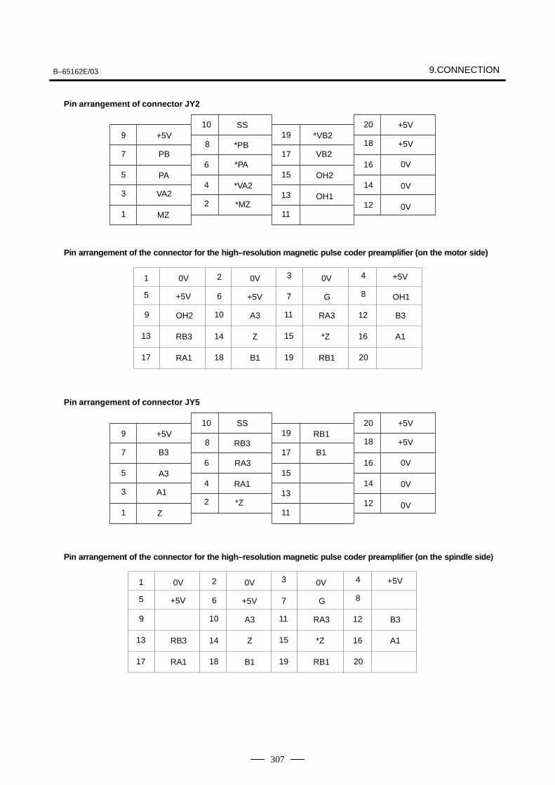
B–65162E/03 9.CONNECTION
307
10 209 19
8 187 17
6 16 0V5 15
4 143 13
2 121 11
Pin arrangement of connector JY2
Pin arrangement of the connector for the high–resolution magnetic pulse coder preamplifier (on the spindle side)
0V
+5V
PB
PA
*PB
*PA
+5V
+5V
0V
0V
+5V
VA2
MZ
SS
*VA2
*MZ
*VB2
VB2
OH2
OH1
RB3
RA1
0V
+5V
0V +5V1
5
9
13
17
2
6
10
14
18
3
7
11
15
19
A3
Z
B1
G
RA3
*Z
RB1
4
8
12
16
20
B3
A1
Pin arrangement of the connector for the high–resolution magnetic pulse coder preamplifier (on the motor side)
0V
+5V
OH2
RB3
RA1
0V
+5V
0V +5V1
5
9
13
17
2
6
10
14
18
3
7
11
15
19
A3
Z
B1
G
RA3
*Z
RB1
4
8
12
16
20
OH1
B3
A1
10 209 19
8 187 17
6 16 0V5 15
4 143 13
2 121 11
Pin arrangement of connector JY5
0V
+5V
B3
A3
RB3
RA3
+5V
+5V
0VA1
Z
SS
RA1
*Z
RB1
B1
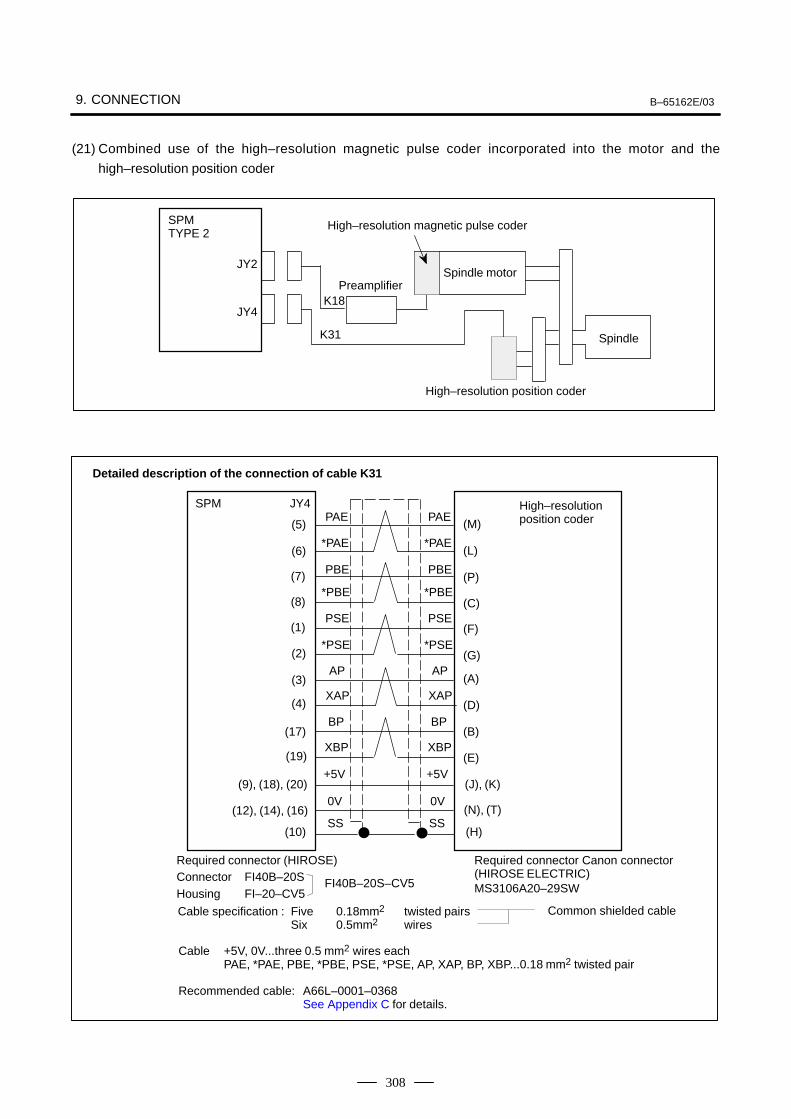
9. CONNECTION B–65162E/03
308
(21) Combined use of the high–resolution magnetic pulse coder incorporated into the motor and the
high–resolution position coder
SPMTYPE 2
JY2
Spindle
Spindle motor
JY4K18
K31
High–resolution magnetic pulse coder
Preamplifier
High–resolution position coder
Cable specification : Five 0.18mm2 twisted pairsSix 0.5mm2 wires
Common shielded cable
Detailed description of the connection of cable K31
SPM JY4
(3)
(4)
(17)
(19)
(N), (T)
(9), (18), (20)
(12), (14), (16)
(10)
(M)
(L)
(P)
(C)
(F)
(G)
(A)
(D)
(B)
(E)
(J), (K)
PAE
*PAE
PBE
PSE
*PSE
+5V
0V
SS
*PBE
SS
Required connector (HIROSE)Connector FI40B–20SHousing FI–20–CV5
Cable +5V, 0V...three 0.5 mm2 wires eachPAE, *PAE, PBE, *PBE, PSE, *PSE, AP, XAP, BP, XBP...0.18 mm2 twisted pair
Recommended cable: A66L–0001–0368See Appendix C for details.
Required connector Canon connector(HIROSE ELECTRIC)MS3106A20–29SWFI40B–20S–CV5
(5)
(6)
(7)
(8)
(1)
(2)
(H)
High–resolution position coder
AP
XAP
BP
XBP
PAE
*PAE
PBE
PSE
*PSE
+5V
0V
*PBE
AP
XAP
BP
XBP
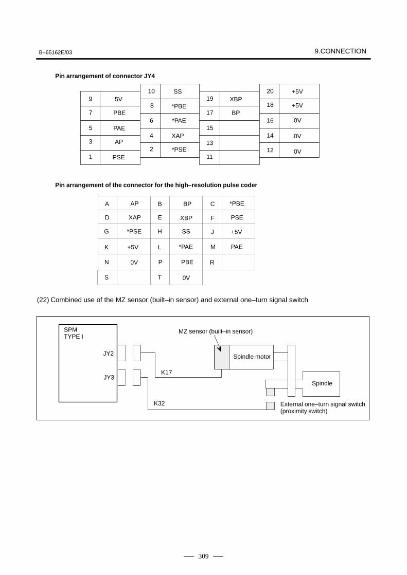
B–65162E/03 9.CONNECTION
309
10 209 19
8 187 17
6 16 0V5 15
4 143 13
2 121 11
Pin arrangement of connector JY4
0V
5V
PBE
PAE
*PBE
*PAE
+5V
+5V
0VAP
PSE
SS
XAP
*PSE
XBP
BP
Pin arrangement of the connector for the high–resolution pulse coder
0V
+5V
0V
A
D
G
K
N
S
B
E
H
L
P
T
AP
XAP
*PSE
C
F
J
M
R
BP
XBP
SS
*PAE
PBE
+5V
*PBE
PSE
PAE
(22) Combined use of the MZ sensor (built–in sensor) and external one–turn signal switch
SPMTYPE I
JY2
JY3K17
K32
Spindle motor
Spindle
External one–turn signal switch(proximity switch)
MZ sensor (built–in sensor)
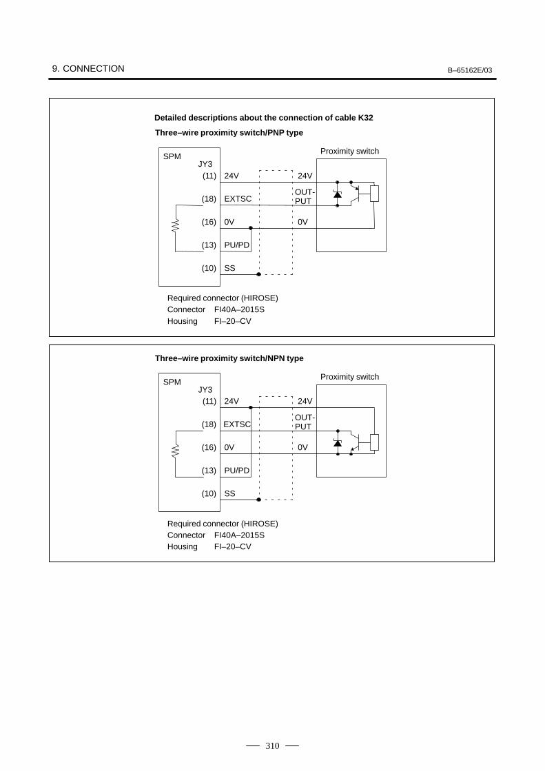
9. CONNECTION B–65162E/03
310
Detailed descriptions about the connection of cable K32
Three–wire proximity switch/PNP type
SPMJY3(11) 24V 24V
(18) EXTSC
(16) 0V 0V
(13) PU/PD
(10) SS
Proximity switch
OUT-PUT
Required connector (HIROSE)Connector FI40A–2015SHousing FI–20–CV
Three–wire proximity switch/NPN type
SPMJY3(11) 24V 24V
(18) EXTSC
(16) 0V 0V
(13) PU/PD
(10) SS
Proximity switch
OUT-PUT
Required connector (HIROSE)Connector FI40A–2015SHousing FI–20–CV
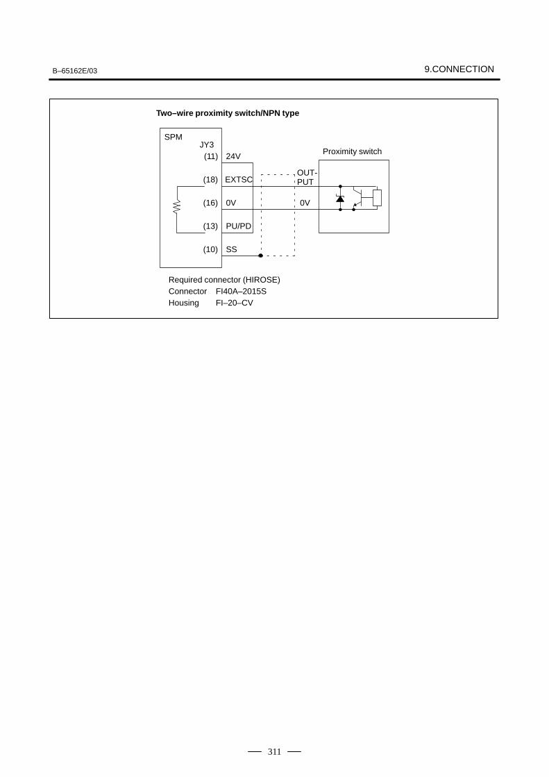
B–65162E/03 9.CONNECTION
311
Two–wire proximity switch/NPN type
SPMJY3(11) 24V
(18) EXTSC
(16) 0V 0V
(13) PU/PD
(10) SS
Proximity switch
OUT-PUT
Required connector (HIROSE)Connector FI40A–2015SHousing FI–20–CV
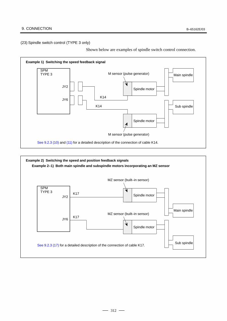
9. CONNECTION B–65162E/03
312
(23) Spindle switch control (TYPE 3 only)
Shown below are examples of spindle switch control connection.
K14
K14
Spindle motor
M sensor (pulse generator) Main spindle
Sub spindle
Spindle motor
SPMTYPE 3
JY2
JY6
See 9.2.3 (10) and (11) for a detailed description of the connection of cable K14.
Example 1) Switching the speed feedback signal
M sensor (pulse generator)
K17
K17
Spindle motor
MZ sensor (built–in sensor)
Main spindle
Sub spindle
Spindle motor
SPMTYPE 3
JY2
JY6
See 9.2.3 (17) for a detailed description of the connection of cable K17.
Example 2) Switching the speed and position feedback signals
Example 2–1) Both main spindle and subspindle motors incorporating an MZ sensor
MZ sensor (built–in sensor)
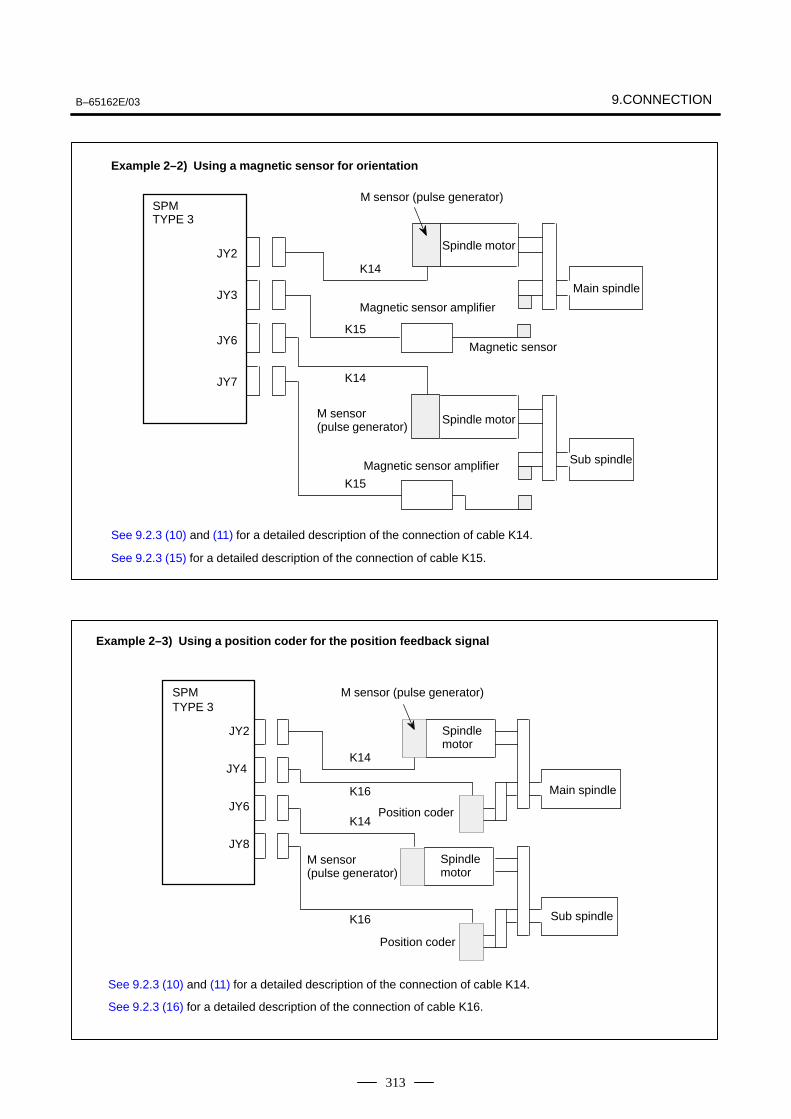
B–65162E/03 9.CONNECTION
313
Example 2–2) Using a magnetic sensor for orientation
SPMTYPE 3
JY2
JY3
JY6
JY7
K14
K15
K14
K15
Spindle motor
M sensor (pulse generator)
Main spindle
Sub spindle
Spindle motor
Magnetic sensor amplifier
Magnetic sensor amplifier
Magnetic sensor
See 9.2.3 (10) and (11) for a detailed description of the connection of cable K14.
See 9.2.3 (15) for a detailed description of the connection of cable K15.
M sensor (pulse generator)
M sensor (pulse generator)
M sensor (pulse generator)
Example 2–3) Using a position coder for the position feedback signal
SPMTYPE 3
JY2
JY6
JY8
JY4K14
K14
K16
K16
Spindle motor
Spindle motor
Position coder
Position coder
Main spindle
Sub spindle
See 9.2.3 (10) and (11) for a detailed description of the connection of cable K14.
See 9.2.3 (16) for a detailed description of the connection of cable K16.
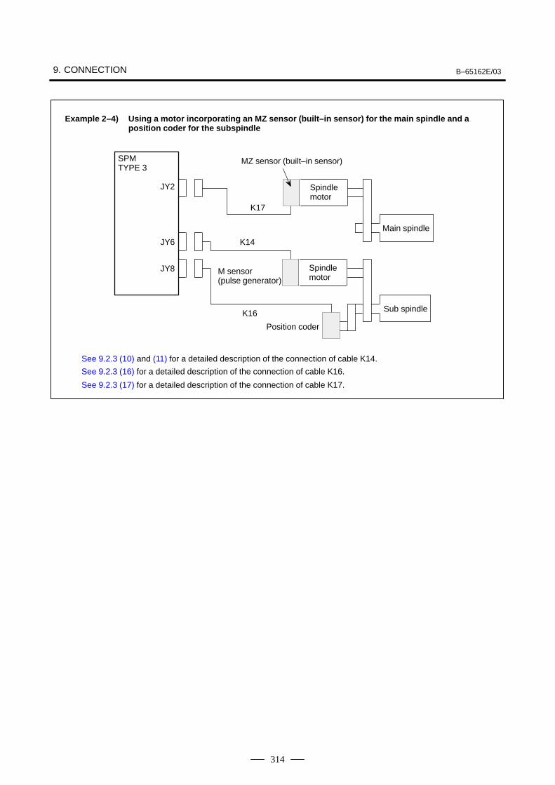
9. CONNECTION B–65162E/03
314
Example 2–4) Using a motor incorporating an MZ sensor (built–in sensor) for the main spindle and a position coder for the subspindle
SPMTYPE 3
JY2
JY6
JY8
K17
K14
K16
Spindle motor
Position coder
Main spindle
Sub spindle
Spindle motor
See 9.2.3 (10) and (11) for a detailed description of the connection of cable K14.
See 9.2.3 (16) for a detailed description of the connection of cable K16.
See 9.2.3 (17) for a detailed description of the connection of cable K17.
MZ sensor (built–in sensor)
M sensor (pulse generator)
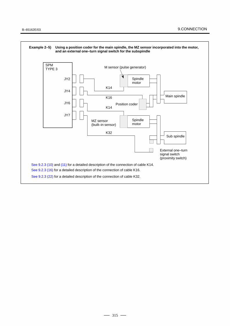
B–65162E/03 9.CONNECTION
315
See 9.2.3 (10) and (11) for a detailed description of the connection of cable K14.
See 9.2.3 (16) for a detailed description of the connection of cable K16.
Example 2–5) Using a position coder for the main spindle, the MZ sensor incorporated into the motor, and an external one–turn signal switch for the subspindle
SPMTYPE 3
JY2
JY4
JY6
JY7
K14
K16
K32
K14
Spindle motor
Spindle motor
Position coder
Main spindle
Sub spindle
External one–turn signal switch (proximity switch)
See 9.2.3 (22) for a detailed description of the connection of cable K32.
MZ sensor(built–in sensor)
M sensor (pulse generator)
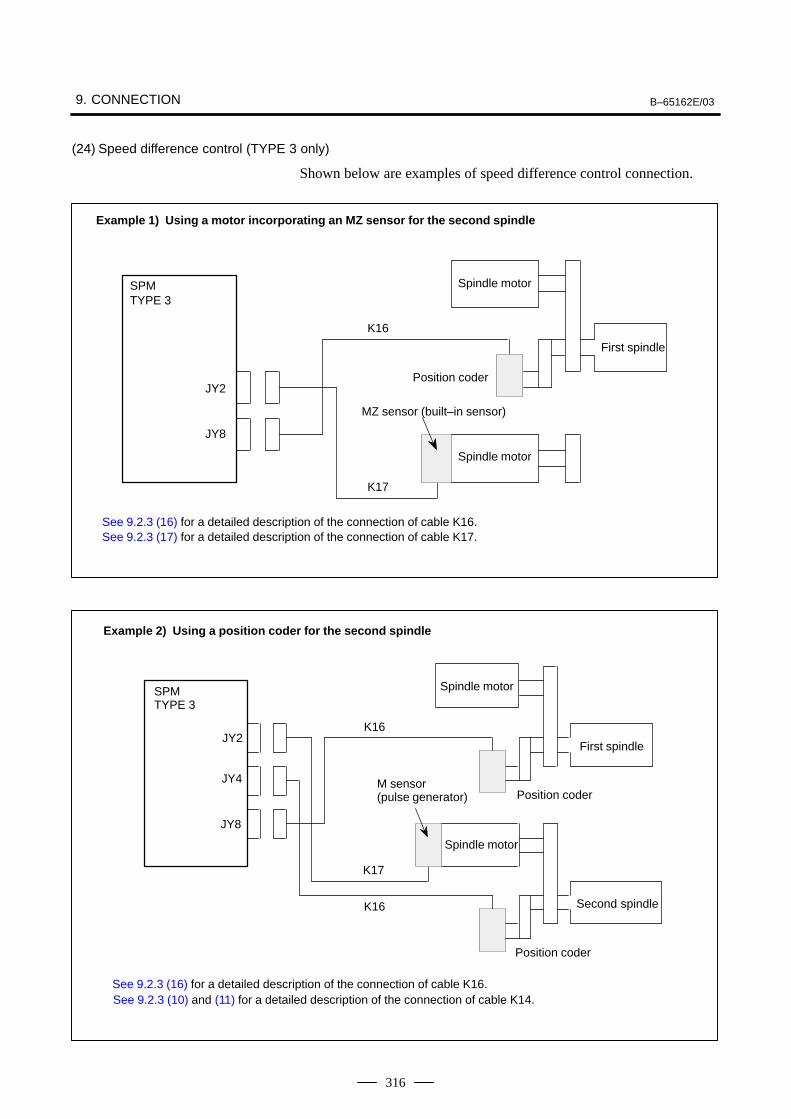
9. CONNECTION B–65162E/03
316
(24) Speed difference control (TYPE 3 only)
Shown below are examples of speed difference control connection.
MZ sensor (built–in sensor)
Example 1) Using a motor incorporating an MZ sensor for the second spindle
SPMTYPE 3
JY2
JY8
K16
K17
Spindle motor
Spindle motor
Position coder
First spindle
See 9.2.3 (16) for a detailed description of the connection of cable K16.See 9.2.3 (17) for a detailed description of the connection of cable K17.
See 9.2.3 (16) for a detailed description of the connection of cable K16.
Example 2) Using a position coder for the second spindle
SPMTYPE 3
JY2
JY4
JY8
K16
K17
K16
Spindle motor
Position coder
First spindle
Spindle motor
Second spindle
Position coder
See 9.2.3 (10) and (11) for a detailed description of the connection of cable K14.
M sensor (pulse generator)
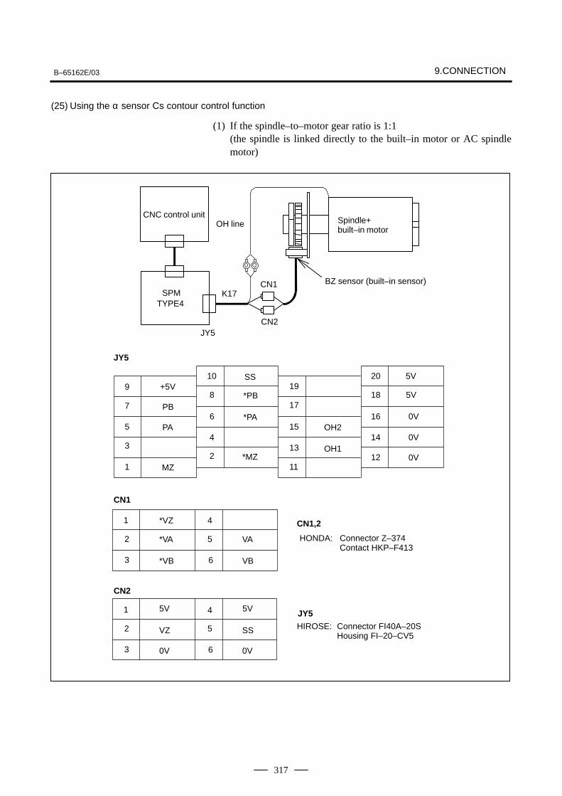
B–65162E/03 9.CONNECTION
317
(25) Using the α sensor Cs contour control function
(1) If the spindle–to–motor gear ratio is 1:1 (the spindle is linked directly to the built–in motor or AC spindlemotor)
10 20
5V
9 +5V 198 18 5V
7 176 16 0V
5 154 14 0V
3 132 12 0V
1 11
JY5
PB
PA
SS
*PB
*PAOH2
OH1
MZ*MZ
6
5
3
2
1
VB
VA
*VB
*VA
4
SS
*VZ
6
5
3
2
1 4
VZ
5V
0V
CN1
CN2
5V
0V
CN1SPM
TYPE4
JY5CN2
K17
CNC control unitSpindle+built–in motor
OH line
HONDA: Connector Z–374Contact HKP–F413
CN1,2
JY5
HIROSE: Connector FI40A–20SHousing FI–20–CV5
BZ sensor (built–in sensor)
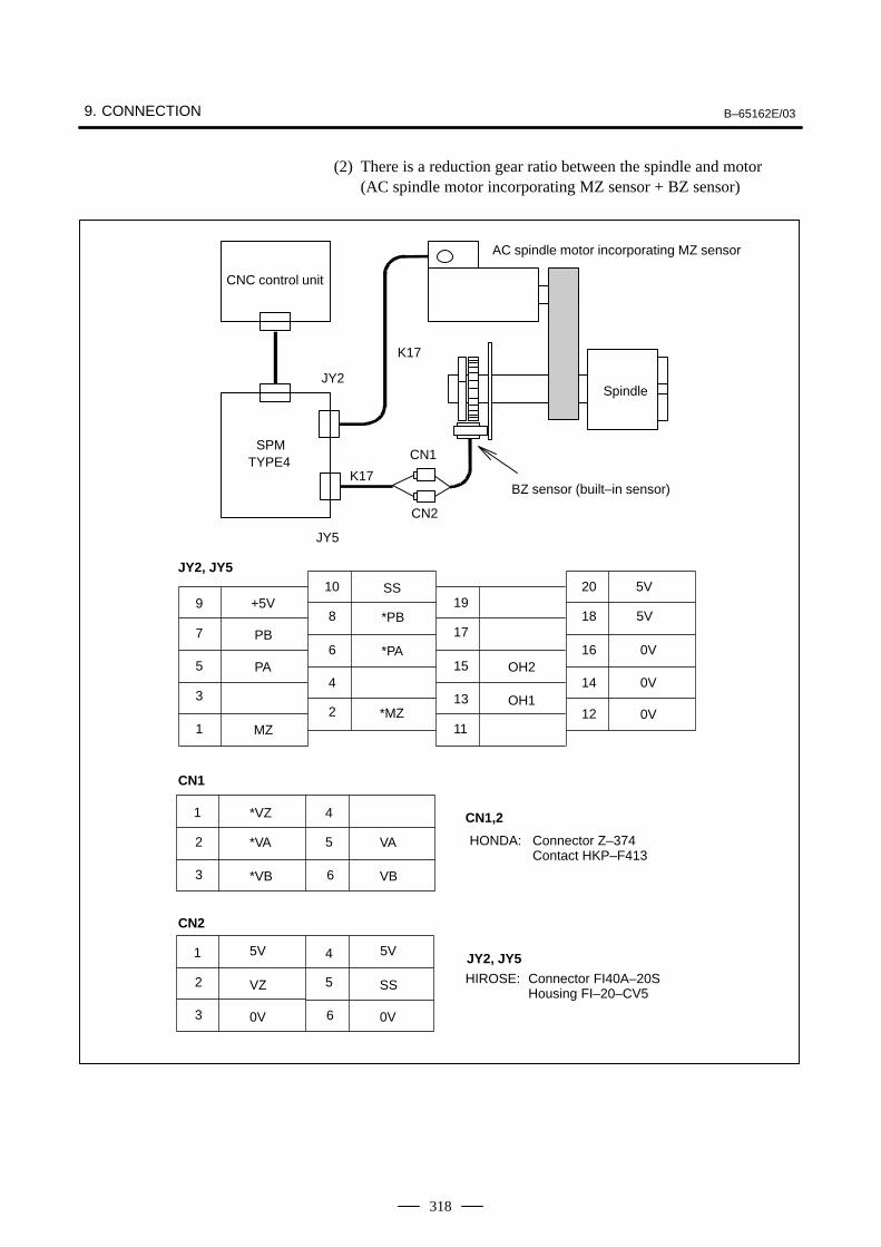
9. CONNECTION B–65162E/03
318
(2) There is a reduction gear ratio between the spindle and motor (AC spindle motor incorporating MZ sensor + BZ sensor)
10 20
5V
9 +5V 198 18 5V
7 176 16 0V
5 154 14 0V
3 132 12 0V
1 11
JY2, JY5
PB
PA
SS
*PB
*PAOH2
OH1
MZ*MZ
6
5
3
2
1
VB
VA
*VB
*VA
4
SS
*VZ
6
5
3
2
1 4
VZ
5V
0V
CN1
CN2
5V
0V
HONDA: Connector Z–374Contact HKP–F413
CN1,2
JY2, JY5
HIROSE: Connector FI40A–20SHousing FI–20–CV5
CN1SPM
TYPE4
JY5
CN2
K17
CNC control unit
Spindle
BZ sensor (built–in sensor)
JY2
K17
AC spindle motor incorporating MZ sensor
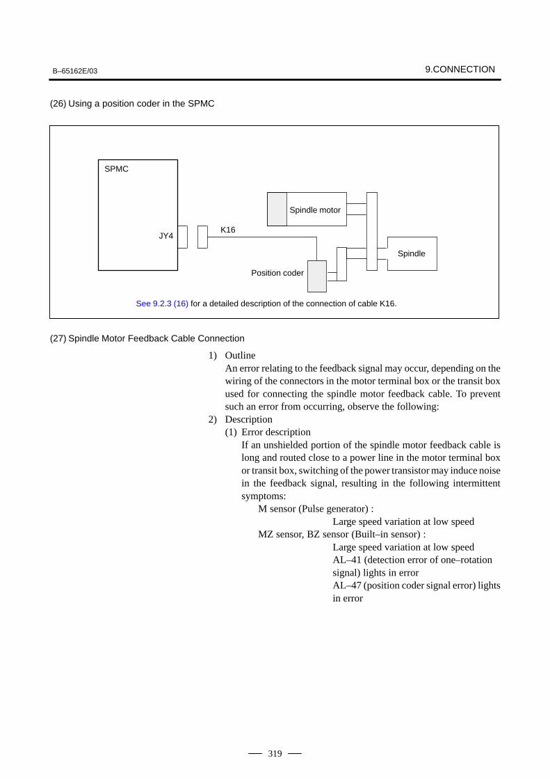
B–65162E/03 9.CONNECTION
319
(26) Using a position coder in the SPMC
SPMC
JY4K16
Spindle motor
Spindle
Position coder
See 9.2.3 (16) for a detailed description of the connection of cable K16.
(27) Spindle Motor Feedback Cable Connection
1) OutlineAn error relating to the feedback signal may occur, depending on thewiring of the connectors in the motor terminal box or the transit boxused for connecting the spindle motor feedback cable. To preventsuch an error from occurring, observe the following:
2) Description(1) Error description
If an unshielded portion of the spindle motor feedback cable islong and routed close to a power line in the motor terminal boxor transit box, switching of the power transistor may induce noisein the feedback signal, resulting in the following intermittentsymptoms:
M sensor (Pulse generator) :Large speed variation at low speed
MZ sensor, BZ sensor (Built–in sensor) :Large speed variation at low speedAL–41 (detection error of one–rotationsignal) lights in errorAL–47 (position coder signal error) lightsin error
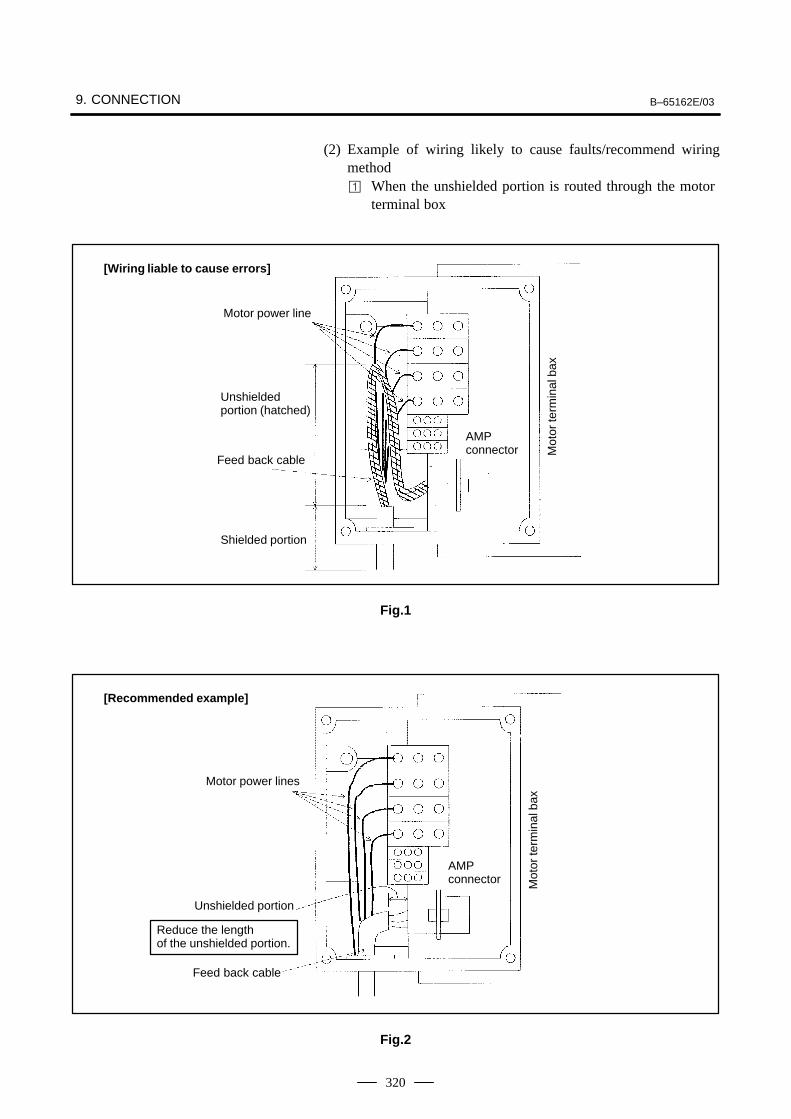
9. CONNECTION B–65162E/03
320
(2) Example of wiring likely to cause faults/recommend wiringmethod When the unshielded portion is routed through the motor
terminal box
[Wiring liable to cause errors]
Unshieldedportion (hatched)
Motor power line
Feed back cable
AMPconnector
Shielded portionM
otor
term
inal
bax
Fig.1
[Recommended example]
Motor power lines
Feed back cable
AMPconnector
Reduce the lengthof the unshielded portion.
Unshielded portion
Mot
or te
rmin
al b
ax
Fig.2
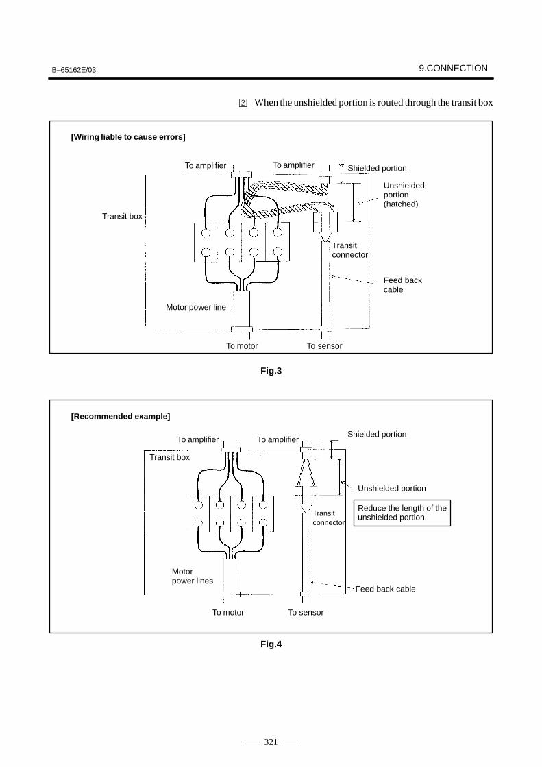
B–65162E/03 9.CONNECTION
321
When the unshielded portion is routed through the transit box
[Wiring liable to cause errors]
To amplifier To amplifier
Transit box
Motor power line
Shielded portion
Transitconnector
Feed backcable
To sensorTo motor
Unshieldedportion(hatched)
Fig.3
[Recommended example]
To amplifier To amplifier
Transit box
Motorpower lines
Shielded portion
Transitconnector
Feed back cable
To sensorTo motor
Unshielded portion
Reduce the length of theunshielded portion.
Fig.4
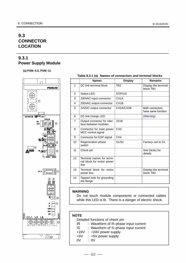
9. CONNECTION B–65162E/03
322
Table.9.3.1 (a) Names of connectors and terminal blocks
Names Display Remarks
1 DC link terminal block TB1 Display the terminalblock TB1
2 Status LED STATUS
3 200VAC input connector CX1A
4 200VAC output connector CX1B
5 24VDC output connector CX2A/CX2B Both connectorshave same function.
6 DC link charge LED (Warning)
7 Output connector for inter-face between modules
JX1B
8 Connector for main powerMCC control signal
CX3
9 Connector for ESP signal CX4
10 Regeneration phaseswitch
S1/S2 Factory–set to S1
11 Check pin See (Note) for details
12 Terminal names for termi-nal block for motor powerline
13 Terminal block for motorpower line
Display the terminalblock TB2
14 Tapped hole for groundingthe flange
WARNINGDo not touch module components or connected cableswhile this LED is lit. There is a danger of electric shock.
NOTEDetailed functions of check pinIR : Waveform of R–phase input currentIS : Waveform of S–phase input current+24V : +24V power supply+5V : +5V power supply0V : 0V
9.3CONNECTORLOCATION
9.3.1Power Supply Module
(a) PSM–5.5, PSM–11
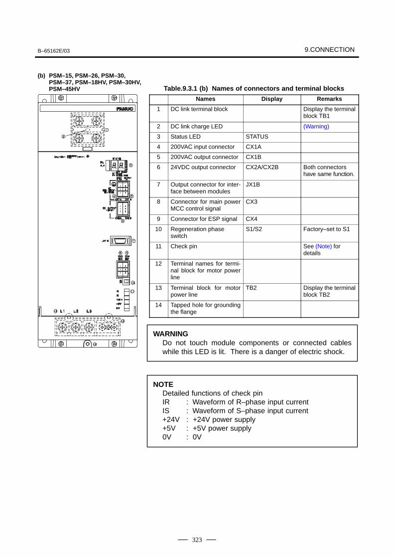
B–65162E/03 9.CONNECTION
323
Table.9.3.1 (b) Names of connectors and terminal blocks
Names Display Remarks
1 DC link terminal block Display the terminalblock TB1
2 DC link charge LED (Warning)
3 Status LED STATUS
4 200VAC input connector CX1A
5 200VAC output connector CX1B
6 24VDC output connector CX2A/CX2B Both connectorshave same function.
7 Output connector for inter-face between modules
JX1B
8 Connector for main powerMCC control signal
CX3
9 Connector for ESP signal CX4
10 Regeneration phaseswitch
S1/S2 Factory–set to S1
11 Check pin See (Note) for details
12 Terminal names for termi-nal block for motor powerline
13 Terminal block for motorpower line
TB2 Display the terminalblock TB2
14 Tapped hole for groundingthe flange
WARNINGDo not touch module components or connected cableswhile this LED is lit. There is a danger of electric shock.
NOTEDetailed functions of check pinIR : Waveform of R–phase input currentIS : Waveform of S–phase input current+24V : +24V power supply+5V : +5V power supply0V : 0V
(b) PSM–15, PSM–26, PSM–30, PSM–37, PSM–18HV, PSM–30HV, PSM–45HV
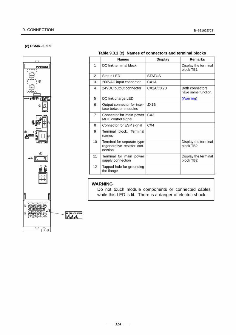
9. CONNECTION B–65162E/03
324
Table.9.3.1 (c) Names of connectors and terminal blocks
Names Display Remarks
1 DC link terminal block Display the terminalblock TB1
2 Status LED STATUS
3 200VAC input connector CX1A
4 24VDC output connector CX2A/CX2B Both connectorshave same function.
5 DC link charge LED (Warning)
6 Output connector for inter-face between modules
JX1B
7 Connector for main powerMCC control signal
CX3
8 Connector for ESP signal CX4
9 Terminal block, Terminalnames
10 Terminal for separate typeregenerative resistor con-nection
Display the terminalblock TB2
11 Terminal for main powersupply connection
Display the terminalblock TB2
12 Tapped hole for groundingthe flange
WARNINGDo not touch module components or connected cableswhile this LED is lit. There is a danger of electric shock.
(c) PSMR–3, 5.5
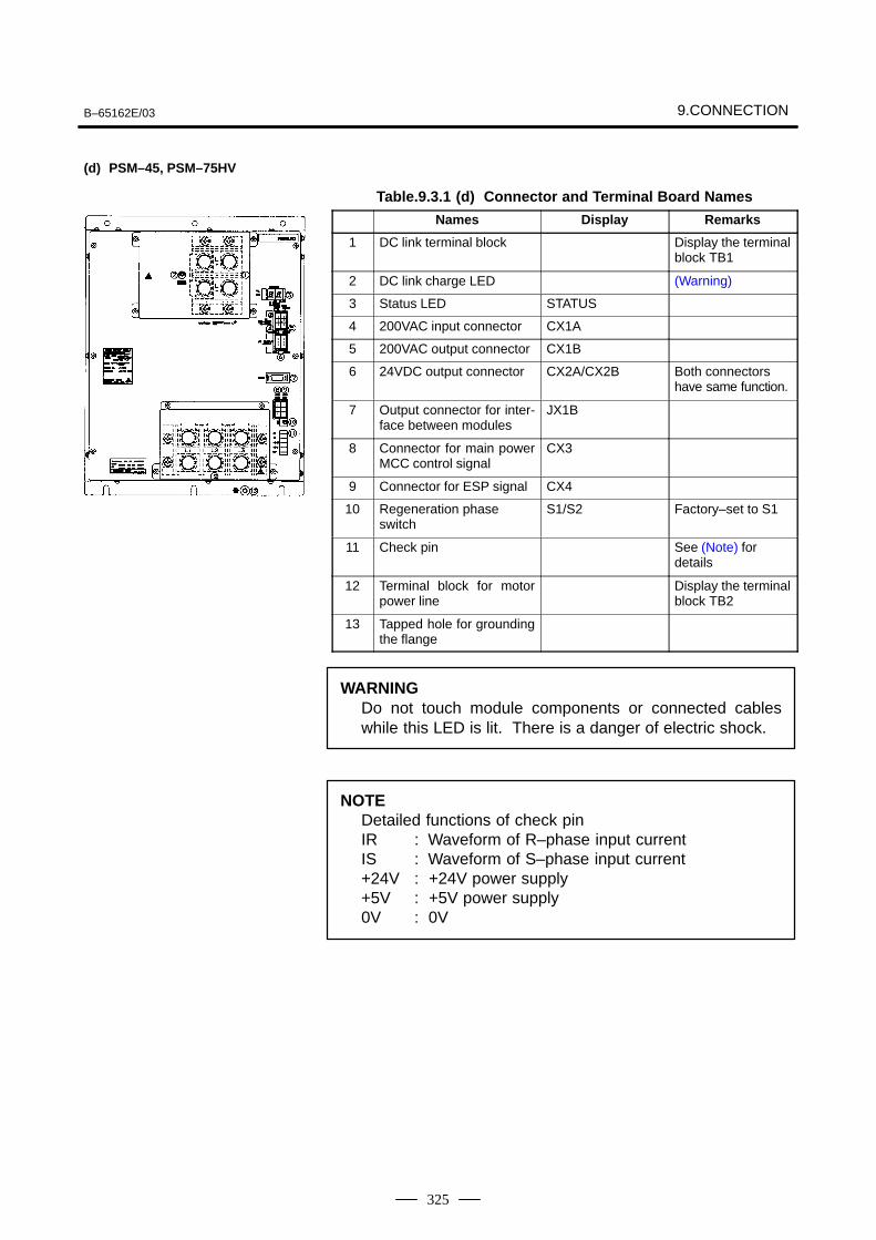
B–65162E/03 9.CONNECTION
325
Table.9.3.1 (d) Connector and Terminal Board Names
Names Display Remarks
1 DC link terminal block Display the terminalblock TB1
2 DC link charge LED (Warning)
3 Status LED STATUS
4 200VAC input connector CX1A
5 200VAC output connector CX1B
6 24VDC output connector CX2A/CX2B Both connectorshave same function.
7 Output connector for inter-face between modules
JX1B
8 Connector for main powerMCC control signal
CX3
9 Connector for ESP signal CX4
10 Regeneration phaseswitch
S1/S2 Factory–set to S1
11 Check pin See (Note) for details
12 Terminal block for motorpower line
Display the terminalblock TB2
13 Tapped hole for groundingthe flange
WARNINGDo not touch module components or connected cableswhile this LED is lit. There is a danger of electric shock.
NOTEDetailed functions of check pinIR : Waveform of R–phase input currentIS : Waveform of S–phase input current+24V : +24V power supply+5V : +5V power supply0V : 0V
(d) PSM–45, PSM–75HV
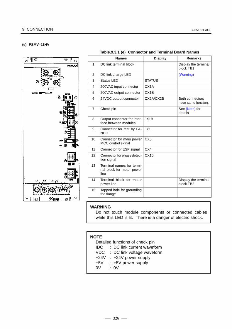
9. CONNECTION B–65162E/03
326
Table.9.3.1 (e) Connector and Terminal Board Names
Names Display Remarks
1 DC link terminal block Display the terminalblock TB1
2 DC link charge LED (Warning)
3 Status LED STATUS
4 200VAC input connector CX1A
5 200VAC output connector CX1B
6 24VDC output connector CX2A/CX2B Both connectorshave same function.
7 Check pin See (Note) for details
8 Output connector for inter-face between modules
JX1B
9 Connector for test by FA-NUC
JY1
10 Connector for main powerMCC control signal
CX3
11 Connector for ESP signal CX4
12 Connector for phase detec-tion signal
CX10
13 Terminal names for termi-nal block for motor powerline
14 Terminal block for motorpower line
Display the terminalblock TB2
15 Tapped hole for groundingthe flange
WARNINGDo not touch module components or connected cableswhile this LED is lit. There is a danger of electric shock.
NOTEDetailed functions of check pinIDC : DC link current waveformVDC : DC link voltage waveform+24V : +24V power supply+5V : +5V power supply0V : 0V
(e) PSMV–11HV
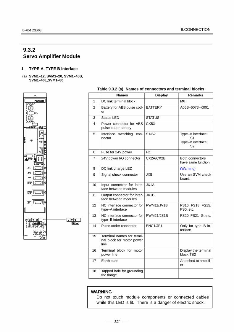
B–65162E/03 9.CONNECTION
327
1. TYPE A, TYPE B Interface
Table.9.3.2 (a) Names of connectors and terminal blocks
Names Display Remarks
1 DC link terminal block M6
2 Battery for ABS pulse cod-er
BATTERY A06B–6073–K001
3 Status LED STATUS
4 Power connector for ABSpulse coder battery
CX5X
5 Interface switching con-nector
S1/S2 Type–A interface:S1
Type–B interface:S2
6 Fuse for 24V power F2
7 24V power I/O connector CX2A/CX2B Both connectorshave same function.
8 DC link charge LED (Warning)
9 Signal check connector JX5 Use an SVM checkboard.
10 Input connector for inter-face between modules
JX1A
11 Output connector for inter-face between modules
JX1B
12 NC interface connector fortype–A interface
PWM11/JV1B FS16, FS18, FS15,FS0, etc.
13 NC interface connector fortype–B interface
PWM21/JS1B FS20, FS21–G, etc.
14 Pulse coder connector ENC1/JF1 Only for type–B in-terface
15 Terminal names for termi-nal block for motor powerline
16 Terminal block for motorpower line
Display the terminalblock TB2
17 Earth plate Attatched to amplifi-er
18 Tapped hole for groundingthe flange
WARNINGDo not touch module components or connected cableswhile this LED is lit. There is a danger of electric shock.
9.3.2Servo Amplifier Module
(a) SVM1–12, SVM1–20, SVM1–40S,SVM1–40L,SVM1–80
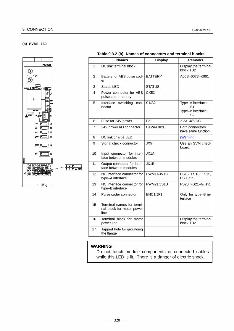
9. CONNECTION B–65162E/03
328
Table.9.3.2 (b) Names of connectors and terminal blocks
Names Display Remarks
1 DC link terminal block Display the terminalblock TB2
2 Battery for ABS pulse cod-er
BATTERY A06B–6073–K001
3 Status LED STATUS
4 Power connector for ABSpulse coder battery
CX5X
5 Interface switching con-nector
S1/S2 Type–A interface:S1
Type–B interface:S2
6 Fuse for 24V power F2 3.2A, 48VDC
7 24V power I/O connector CX2A/CX2B Both connectorshave same function.
8 DC link charge LED (Warning)
9 Signal check connector JX5 Use an SVM checkboard.
10 Input connector for inter-face between modules
JX1A
11 Output connector for inter-face between modules
JX1B
12 NC interface connector fortype–A interface
PWM11/JV1B FS16, FS18, FS15,FS0, etc.
13 NC interface connector fortype–B interface
PWM21/JS1B FS20, FS21–G, etc.
14 Pulse coder connector ENC1/JF1 Only for type–B in-terface
15 Terminal names for termi-nal block for motor powerline
16 Terminal block for motorpower line
Display the terminalblock TB2
17 Tapped hole for groundingthe flange
WARNINGDo not touch module components or connected cableswhile this LED is lit. There is a danger of electric shock.
(b) SVM1–130
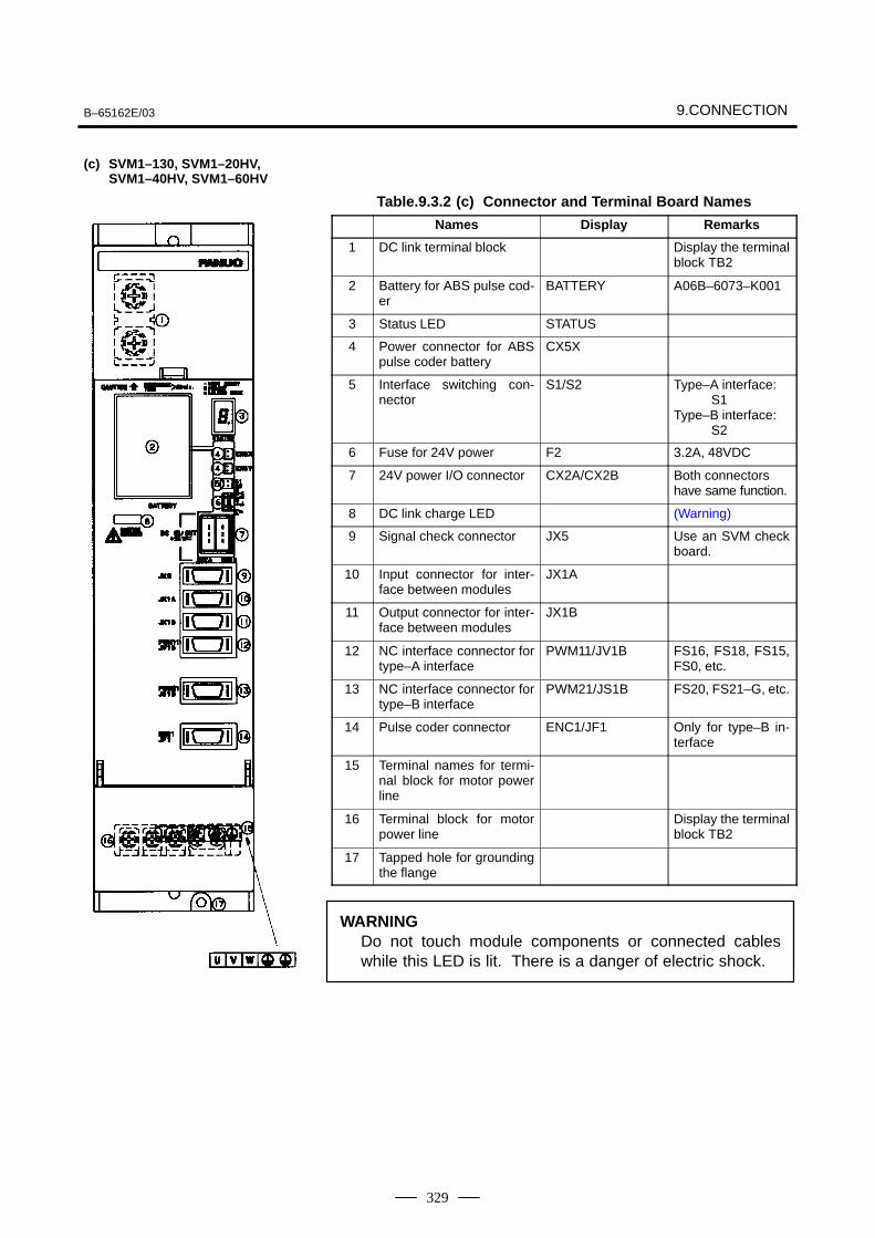
B–65162E/03 9.CONNECTION
329
Table.9.3.2 (c) Connector and Terminal Board Names
Names Display Remarks
1 DC link terminal block Display the terminalblock TB2
2 Battery for ABS pulse cod-er
BATTERY A06B–6073–K001
3 Status LED STATUS
4 Power connector for ABSpulse coder battery
CX5X
5 Interface switching con-nector
S1/S2 Type–A interface:S1
Type–B interface:S2
6 Fuse for 24V power F2 3.2A, 48VDC
7 24V power I/O connector CX2A/CX2B Both connectorshave same function.
8 DC link charge LED (Warning)
9 Signal check connector JX5 Use an SVM checkboard.
10 Input connector for inter-face between modules
JX1A
11 Output connector for inter-face between modules
JX1B
12 NC interface connector fortype–A interface
PWM11/JV1B FS16, FS18, FS15,FS0, etc.
13 NC interface connector fortype–B interface
PWM21/JS1B FS20, FS21–G, etc.
14 Pulse coder connector ENC1/JF1 Only for type–B in-terface
15 Terminal names for termi-nal block for motor powerline
16 Terminal block for motorpower line
Display the terminalblock TB2
17 Tapped hole for groundingthe flange
WARNINGDo not touch module components or connected cableswhile this LED is lit. There is a danger of electric shock.
(c) SVM1–130, SVM1–20HV,SVM1–40HV, SVM1–60HV
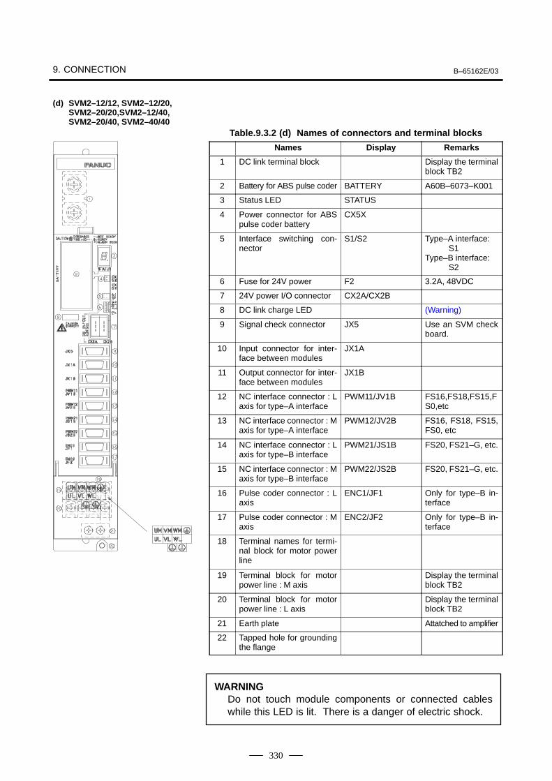
9. CONNECTION B–65162E/03
330
Table.9.3.2 (d) Names of connectors and terminal blocks
Names Display Remarks
1 DC link terminal block Display the terminalblock TB2
2 Battery for ABS pulse coder BATTERY A60B–6073–K001
3 Status LED STATUS
4 Power connector for ABSpulse coder battery
CX5X
5 Interface switching con-nector
S1/S2 Type–A interface:S1
Type–B interface:S2
6 Fuse for 24V power F2 3.2A, 48VDC
7 24V power I/O connector CX2A/CX2B
8 DC link charge LED (Warning)
9 Signal check connector JX5 Use an SVM checkboard.
10 Input connector for inter-face between modules
JX1A
11 Output connector for inter-face between modules
JX1B
12 NC interface connector : Laxis for type–A interface
PWM11/JV1B FS16,FS18,FS15,FS0,etc
13 NC interface connector : Maxis for type–A interface
PWM12/JV2B FS16, FS18, FS15,FS0, etc
14 NC interface connector : Laxis for type–B interface
PWM21/JS1B FS20, FS21–G, etc.
15 NC interface connector : Maxis for type–B interface
PWM22/JS2B FS20, FS21–G, etc.
16 Pulse coder connector : Laxis
ENC1/JF1 Only for type–B in-terface
17 Pulse coder connector : Maxis
ENC2/JF2 Only for type–B in-terface
18 Terminal names for termi-nal block for motor powerline
19 Terminal block for motorpower line : M axis
Display the terminalblock TB2
20 Terminal block for motorpower line : L axis
Display the terminalblock TB2
21 Earth plate Attatched to amplifier
22 Tapped hole for groundingthe flange
WARNINGDo not touch module components or connected cableswhile this LED is lit. There is a danger of electric shock.
(d) SVM2–12/12, SVM2–12/20,SVM2–20/20,SVM2–12/40,SVM2–20/40, SVM2–40/40
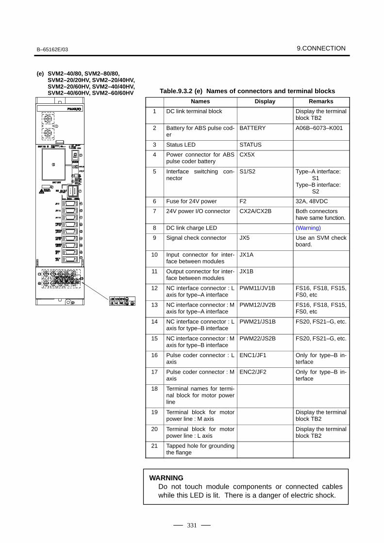
B–65162E/03 9.CONNECTION
331
Table.9.3.2 (e) Names of connectors and terminal blocks
Names Display Remarks
1 DC link terminal block Display the terminalblock TB2
2 Battery for ABS pulse cod-er
BATTERY A06B–6073–K001
3 Status LED STATUS
4 Power connector for ABSpulse coder battery
CX5X
5 Interface switching con-nector
S1/S2 Type–A interface:S1
Type–B interface:S2
6 Fuse for 24V power F2 32A, 48VDC
7 24V power I/O connector CX2A/CX2B Both connectorshave same function.
8 DC link charge LED (Warning)
9 Signal check connector JX5 Use an SVM checkboard.
10 Input connector for inter-face between modules
JX1A
11 Output connector for inter-face between modules
JX1B
12 NC interface connector : Laxis for type–A interface
PWM11/JV1B FS16, FS18, FS15,FS0, etc
13 NC interface connector : Maxis for type–A interface
PWM12/JV2B FS16, FS18, FS15,FS0, etc
14 NC interface connector : Laxis for type–B interface
PWM21/JS1B FS20, FS21–G, etc.
15 NC interface connector : Maxis for type–B interface
PWM22/JS2B FS20, FS21–G, etc.
16 Pulse coder connector : Laxis
ENC1/JF1 Only for type–B in-terface
17 Pulse coder connector : Maxis
ENC2/JF2 Only for type–B in-terface
18 Terminal names for termi-nal block for motor powerline
19 Terminal block for motorpower line : M axis
Display the terminalblock TB2
20 Terminal block for motorpower line : L axis
Display the terminalblock TB2
21 Tapped hole for groundingthe flange
WARNINGDo not touch module components or connected cableswhile this LED is lit. There is a danger of electric shock.
(e) SVM2–40/80, SVM2–80/80,SVM2–20/20HV, SVM2–20/40HV,SVM2–20/60HV, SVM2–40/40HV,SVM2–40/60HV, SVM2–60/60HV
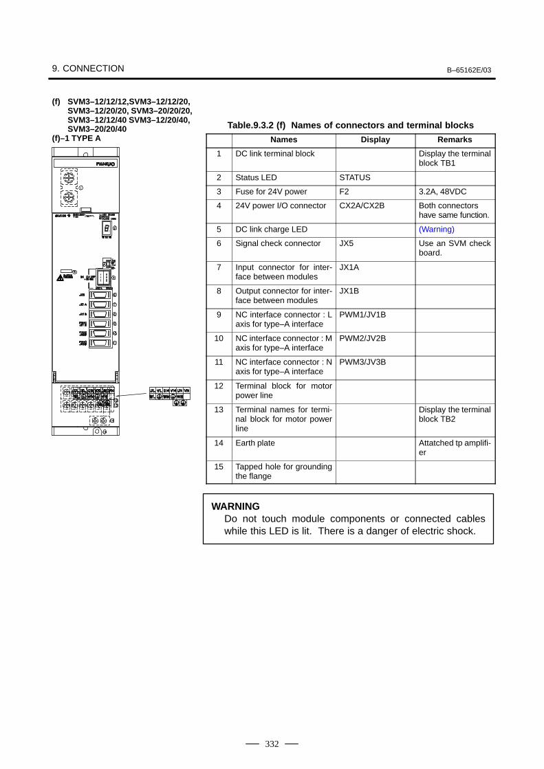
9. CONNECTION B–65162E/03
332
Table.9.3.2 (f) Names of connectors and terminal blocks
Names Display Remarks
1 DC link terminal block Display the terminalblock TB1
2 Status LED STATUS
3 Fuse for 24V power F2 3.2A, 48VDC
4 24V power I/O connector CX2A/CX2B Both connectorshave same function.
5 DC link charge LED (Warning)
6 Signal check connector JX5 Use an SVM checkboard.
7 Input connector for inter-face between modules
JX1A
8 Output connector for inter-face between modules
JX1B
9 NC interface connector : Laxis for type–A interface
PWM1/JV1B
10 NC interface connector : Maxis for type–A interface
PWM2/JV2B
11 NC interface connector : Naxis for type–A interface
PWM3/JV3B
12 Terminal block for motorpower line
13 Terminal names for termi-nal block for motor powerline
Display the terminalblock TB2
14 Earth plate Attatched tp amplifi-er
15 Tapped hole for groundingthe flange
WARNINGDo not touch module components or connected cableswhile this LED is lit. There is a danger of electric shock.
(f) SVM3–12/12/12,SVM3–12/12/20,SVM3–12/20/20, SVM3–20/20/20,SVM3–12/12/40 SVM3–12/20/40,SVM3–20/20/40
(f)–1 TYPE A
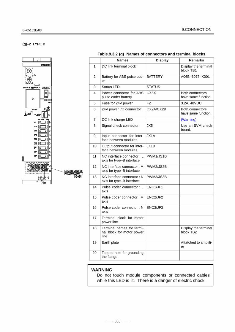
B–65162E/03 9.CONNECTION
333
Table.9.3.2 (g) Names of connectors and terminal blocks
Names Display Remarks
1 DC link terminal block Display the terminalblock TB1
2 Battery for ABS pulse cod-er
BATTERY A06B–6073–K001
3 Status LED STATUS
4 Power connector for ABSpulse coder battery
CX5X Both connectorshave same function.
5 Fuse for 24V power F2 3.2A, 48VDC
6 24V power I/O connector CX2A/CX2B Both connectorshave same function.
7 DC link charge LED (Warning)
8 Signal check connector JX5 Use an SVM checkboard.
9 Input connector for inter-face between modules
JX1A
10 Output connector for inter-face between modules
JX1B
11 NC interface connector : Laxis for type–B interface
PWM1/JS1B
12 NC interface connector : Maxis for type–B interface
PWM2/JS2B
13 NC interface connector : Naxis for type–B interface
PWM3/JS3B
14 Pulse coder connector : Laxis
ENC1/JF1
15 Pulse coder connector : Maxis
ENC2/JF2
16 Pulse coder connector : Naxis
ENC3/JF3
17 Terminal block for motorpower line
18 Terminal names for termi-nal block for motor powerline
Display the terminalblock TB2
19 Earth plate Attatched to amplifi-er
20 Tapped hole for groundingthe flange
WARNINGDo not touch module components or connected cableswhile this LED is lit. There is a danger of electric shock.
(g)–2 TYPE B
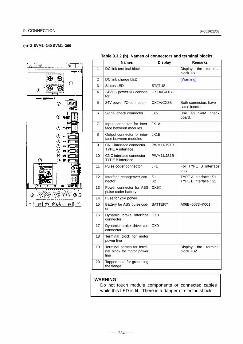
9. CONNECTION B–65162E/03
334
Table.9.3.2 (h) Names of connectors and terminal blocks
Names Display Remarks
1 DC link terminal block Display the terminalblock TB1
2 DC link charge LED (Warning)
3 Status LED STATUS
4 24VDC power I/O connec-tor
CX1A/CX1B
5 24V power I/O connector CX2A/CX2B Both connectors havesame function.
6 Signal check connector JX5 Use an SVM checkboard.
7 Input connector for inter-face between modules
JX1A
8 Output connector for inter-face between modules
JX1B
9 CNC interface connectorTYPE A interface
PWM11/JV1B
10 CNC interface connectorTYPE B interface
PWM11/JS1B
11 Pulse coder connector JF1 For TYPE B interfaceonly
12 Interface changeover con-nector
S1S2
TYPE A Interface : S1TYPE B Interface : S2
13 Power connector for ABSpulse coder battery
CX5X
14 Fuse for 24V power
15 Battery for ABS pulse cod-er
BATTERY A06B–6073–K001
16 Dynamic brake interfaceconnector
CX8
17 Dynamic brake drive coilconnector
CX9
18 Terminal block for motorpower line
19 Terminal names for termi-nal block for motor powerline
Display the terminalblock TB2
20 Tapped hole for groundingthe flange
WARNINGDo not touch module components or connected cableswhile this LED is lit. There is a danger of electric shock.
(h)–2 SVM1–240 SVM1–360
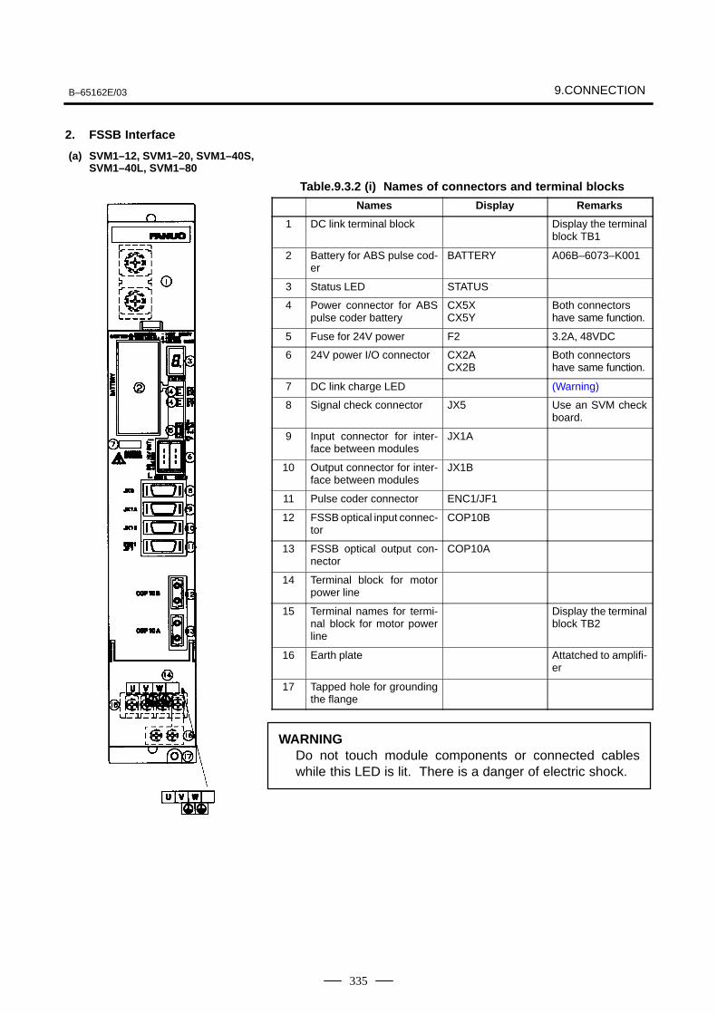
B–65162E/03 9.CONNECTION
335
2. FSSB Interface
Table.9.3.2 (i) Names of connectors and terminal blocks
Names Display Remarks
1 DC link terminal block Display the terminalblock TB1
2 Battery for ABS pulse cod-er
BATTERY A06B–6073–K001
3 Status LED STATUS
4 Power connector for ABSpulse coder battery
CX5XCX5Y
Both connectorshave same function.
5 Fuse for 24V power F2 3.2A, 48VDC
6 24V power I/O connector CX2ACX2B
Both connectorshave same function.
7 DC link charge LED (Warning)
8 Signal check connector JX5 Use an SVM checkboard.
9 Input connector for inter-face between modules
JX1A
10 Output connector for inter-face between modules
JX1B
11 Pulse coder connector ENC1/JF1
12 FSSB optical input connec-tor
COP10B
13 FSSB optical output con-nector
COP10A
14 Terminal block for motorpower line
15 Terminal names for termi-nal block for motor powerline
Display the terminalblock TB2
16 Earth plate Attatched to amplifi-er
17 Tapped hole for groundingthe flange
WARNINGDo not touch module components or connected cableswhile this LED is lit. There is a danger of electric shock.
(a) SVM1–12, SVM1–20, SVM1–40S,SVM1–40L, SVM1–80
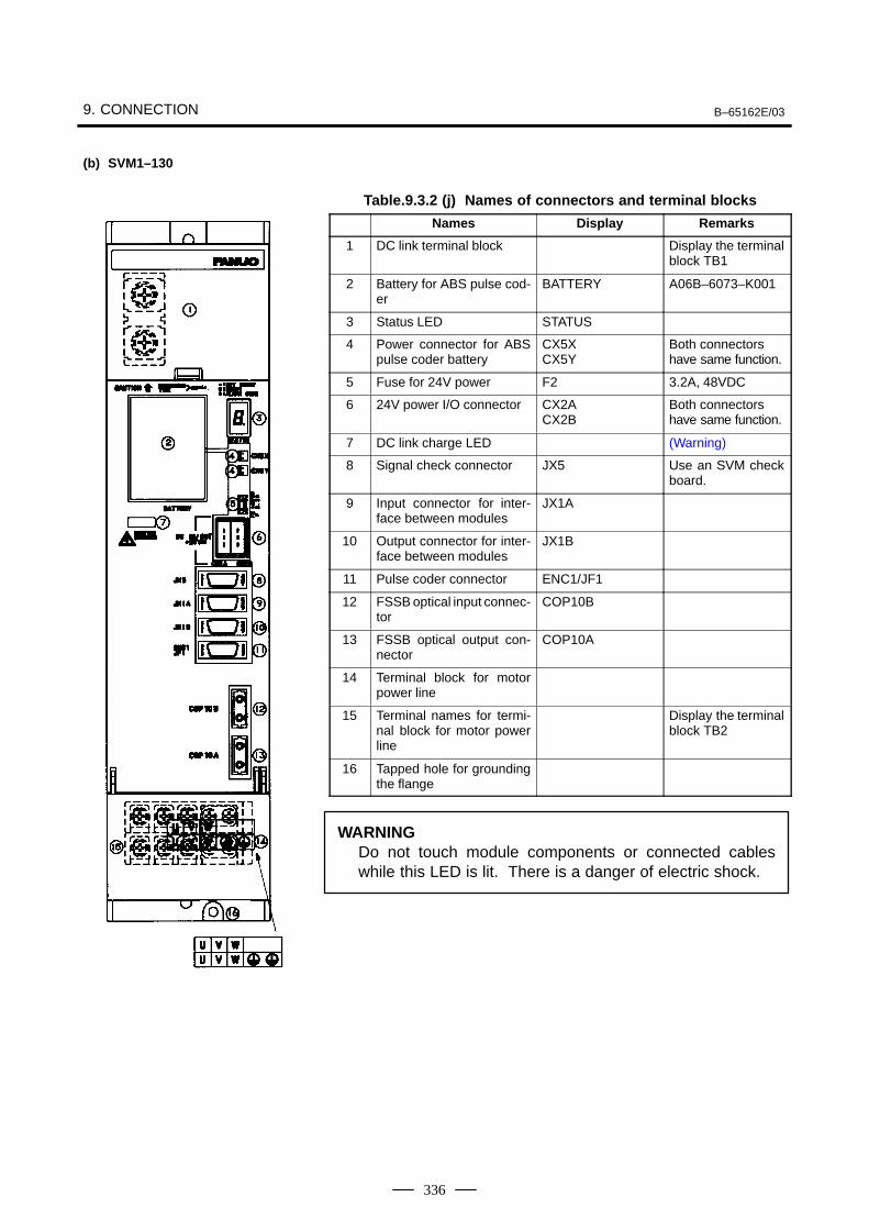
9. CONNECTION B–65162E/03
336
Table.9.3.2 (j) Names of connectors and terminal blocks
Names Display Remarks
1 DC link terminal block Display the terminalblock TB1
2 Battery for ABS pulse cod-er
BATTERY A06B–6073–K001
3 Status LED STATUS
4 Power connector for ABSpulse coder battery
CX5XCX5Y
Both connectorshave same function.
5 Fuse for 24V power F2 3.2A, 48VDC
6 24V power I/O connector CX2ACX2B
Both connectorshave same function.
7 DC link charge LED (Warning)
8 Signal check connector JX5 Use an SVM checkboard.
9 Input connector for inter-face between modules
JX1A
10 Output connector for inter-face between modules
JX1B
11 Pulse coder connector ENC1/JF1
12 FSSB optical input connec-tor
COP10B
13 FSSB optical output con-nector
COP10A
14 Terminal block for motorpower line
15 Terminal names for termi-nal block for motor powerline
Display the terminalblock TB2
16 Tapped hole for groundingthe flange
WARNINGDo not touch module components or connected cableswhile this LED is lit. There is a danger of electric shock.
(b) SVM1–130
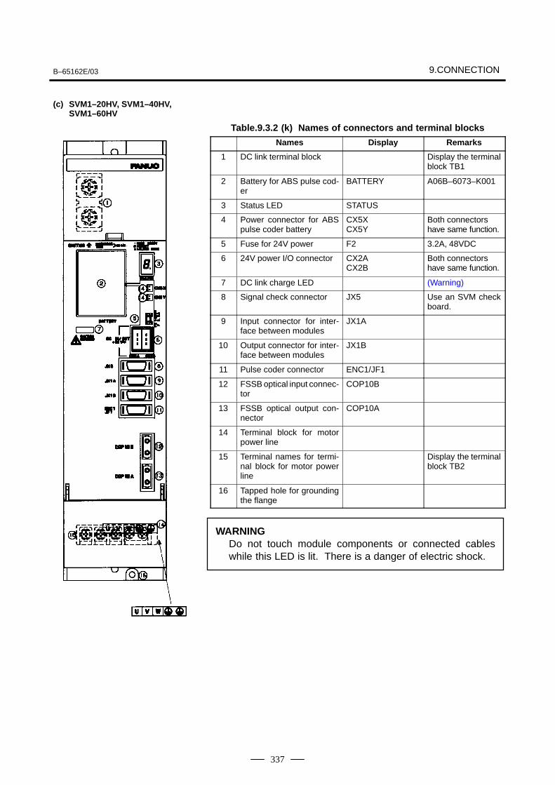
B–65162E/03 9.CONNECTION
337
Table.9.3.2 (k) Names of connectors and terminal blocks
Names Display Remarks
1 DC link terminal block Display the terminalblock TB1
2 Battery for ABS pulse cod-er
BATTERY A06B–6073–K001
3 Status LED STATUS
4 Power connector for ABSpulse coder battery
CX5XCX5Y
Both connectorshave same function.
5 Fuse for 24V power F2 3.2A, 48VDC
6 24V power I/O connector CX2ACX2B
Both connectorshave same function.
7 DC link charge LED (Warning)
8 Signal check connector JX5 Use an SVM checkboard.
9 Input connector for inter-face between modules
JX1A
10 Output connector for inter-face between modules
JX1B
11 Pulse coder connector ENC1/JF1
12 FSSB optical input connec-tor
COP10B
13 FSSB optical output con-nector
COP10A
14 Terminal block for motorpower line
15 Terminal names for termi-nal block for motor powerline
Display the terminalblock TB2
16 Tapped hole for groundingthe flange
WARNINGDo not touch module components or connected cableswhile this LED is lit. There is a danger of electric shock.
(c) SVM1–20HV, SVM1–40HV,SVM1–60HV
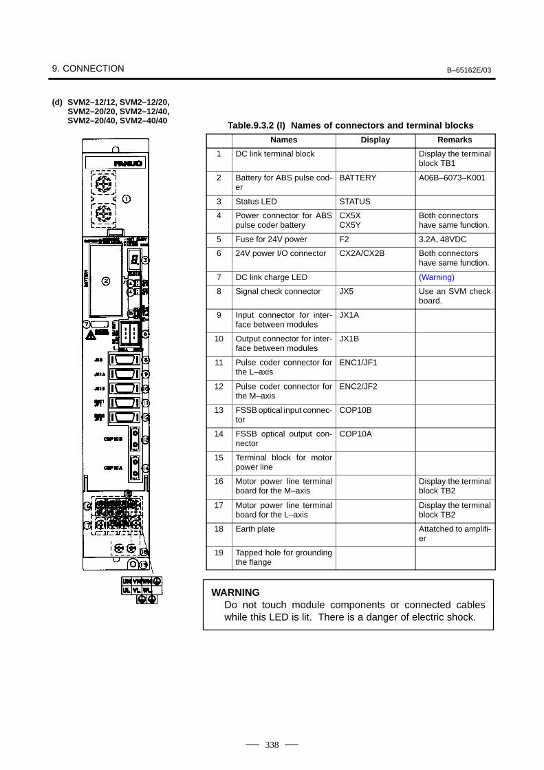
9. CONNECTION B–65162E/03
338
Table.9.3.2 (l) Names of connectors and terminal blocks
Names Display Remarks
1 DC link terminal block Display the terminalblock TB1
2 Battery for ABS pulse cod-er
BATTERY A06B–6073–K001
3 Status LED STATUS
4 Power connector for ABSpulse coder battery
CX5XCX5Y
Both connectorshave same function.
5 Fuse for 24V power F2 3.2A, 48VDC
6 24V power I/O connector CX2A/CX2B Both connectorshave same function.
7 DC link charge LED (Warning)
8 Signal check connector JX5 Use an SVM checkboard.
9 Input connector for inter-face between modules
JX1A
10 Output connector for inter-face between modules
JX1B
11 Pulse coder connector forthe L–axis
ENC1/JF1
12 Pulse coder connector forthe M–axis
ENC2/JF2
13 FSSB optical input connec-tor
COP10B
14 FSSB optical output con-nector
COP10A
15 Terminal block for motorpower line
16 Motor power line terminalboard for the M–axis
Display the terminalblock TB2
17 Motor power line terminalboard for the L–axis
Display the terminalblock TB2
18 Earth plate Attatched to amplifi-er
19 Tapped hole for groundingthe flange
WARNINGDo not touch module components or connected cableswhile this LED is lit. There is a danger of electric shock.
(d) SVM2–12/12, SVM2–12/20,SVM2–20/20, SVM2–12/40,SVM2–20/40, SVM2–40/40
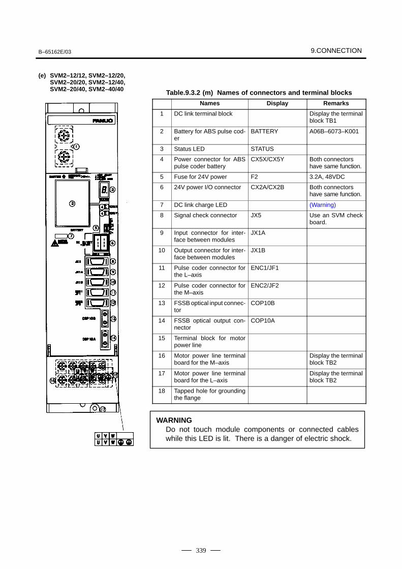
B–65162E/03 9.CONNECTION
339
Table.9.3.2 (m) Names of connectors and terminal blocks
Names Display Remarks
1 DC link terminal block Display the terminalblock TB1
2 Battery for ABS pulse cod-er
BATTERY A06B–6073–K001
3 Status LED STATUS
4 Power connector for ABSpulse coder battery
CX5X/CX5Y Both connectorshave same function.
5 Fuse for 24V power F2 3.2A, 48VDC
6 24V power I/O connector CX2A/CX2B Both connectorshave same function.
7 DC link charge LED (Warning)
8 Signal check connector JX5 Use an SVM checkboard.
9 Input connector for inter-face between modules
JX1A
10 Output connector for inter-face between modules
JX1B
11 Pulse coder connector forthe L–axis
ENC1/JF1
12 Pulse coder connector forthe M–axis
ENC2/JF2
13 FSSB optical input connec-tor
COP10B
14 FSSB optical output con-nector
COP10A
15 Terminal block for motorpower line
16 Motor power line terminalboard for the M–axis
Display the terminalblock TB2
17 Motor power line terminalboard for the L–axis
Display the terminalblock TB2
18 Tapped hole for groundingthe flange
WARNINGDo not touch module components or connected cableswhile this LED is lit. There is a danger of electric shock.
(e) SVM2–12/12, SVM2–12/20,SVM2–20/20, SVM2–12/40,SVM2–20/40, SVM2–40/40
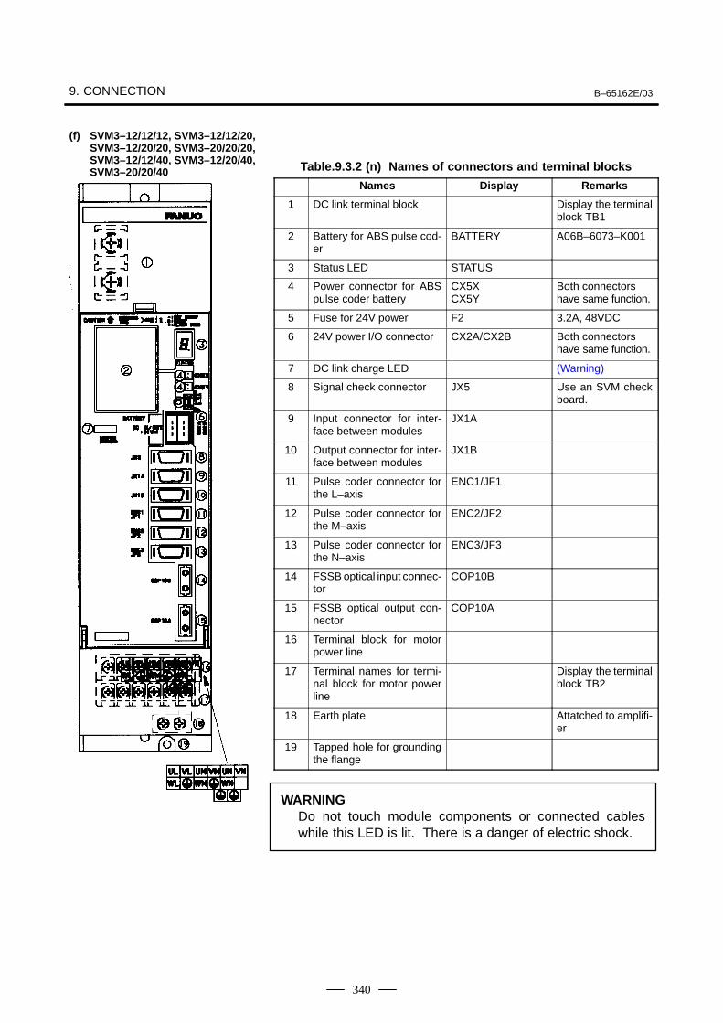
9. CONNECTION B–65162E/03
340
Table.9.3.2 (n) Names of connectors and terminal blocks
Names Display Remarks
1 DC link terminal block Display the terminalblock TB1
2 Battery for ABS pulse cod-er
BATTERY A06B–6073–K001
3 Status LED STATUS
4 Power connector for ABSpulse coder battery
CX5XCX5Y
Both connectorshave same function.
5 Fuse for 24V power F2 3.2A, 48VDC
6 24V power I/O connector CX2A/CX2B Both connectorshave same function.
7 DC link charge LED (Warning)
8 Signal check connector JX5 Use an SVM checkboard.
9 Input connector for inter-face between modules
JX1A
10 Output connector for inter-face between modules
JX1B
11 Pulse coder connector forthe L–axis
ENC1/JF1
12 Pulse coder connector forthe M–axis
ENC2/JF2
13 Pulse coder connector forthe N–axis
ENC3/JF3
14 FSSB optical input connec-tor
COP10B
15 FSSB optical output con-nector
COP10A
16 Terminal block for motorpower line
17 Terminal names for termi-nal block for motor powerline
Display the terminalblock TB2
18 Earth plate Attatched to amplifi-er
19 Tapped hole for groundingthe flange
WARNINGDo not touch module components or connected cableswhile this LED is lit. There is a danger of electric shock.
(f) SVM3–12/12/12, SVM3–12/12/20,SVM3–12/20/20, SVM3–20/20/20,SVM3–12/12/40, SVM3–12/20/40,SVM3–20/20/40
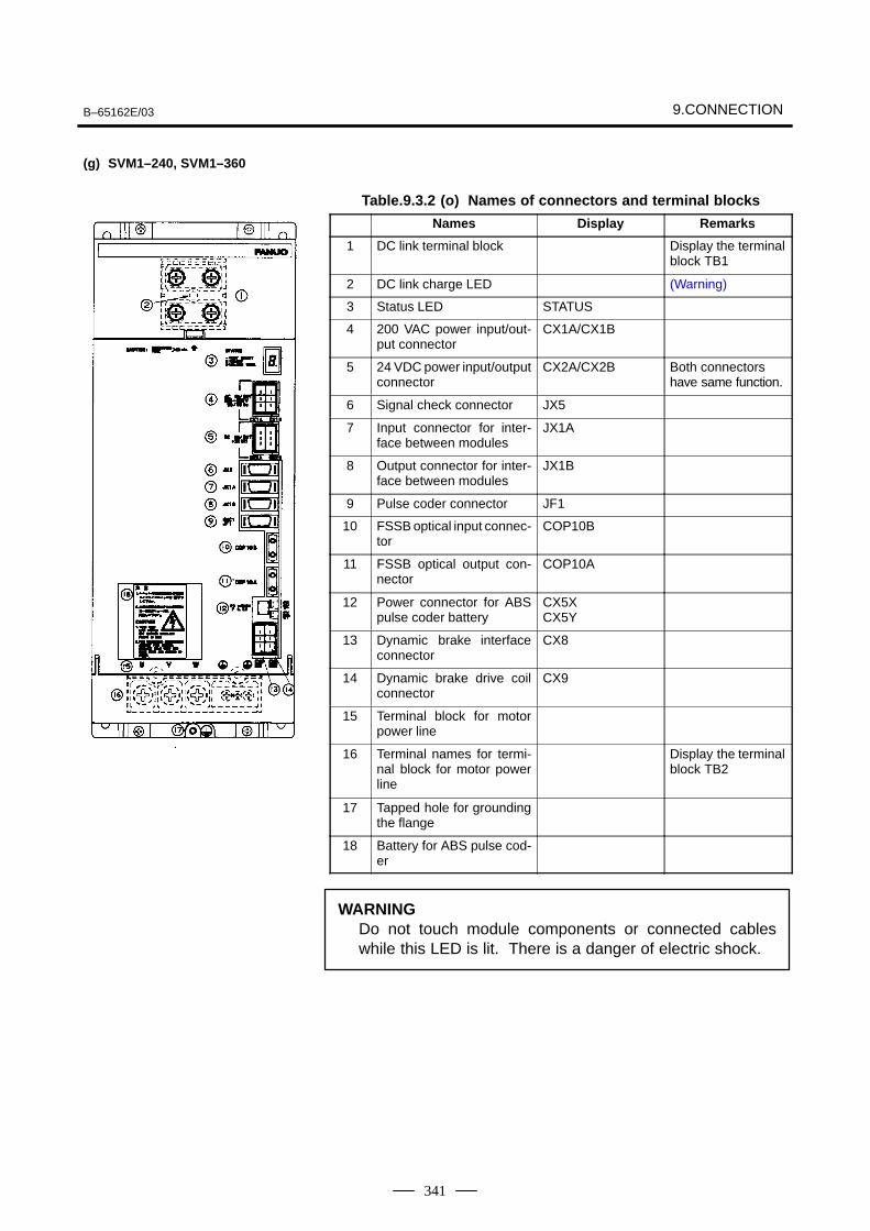
B–65162E/03 9.CONNECTION
341
Table.9.3.2 (o) Names of connectors and terminal blocks
Names Display Remarks
1 DC link terminal block Display the terminalblock TB1
2 DC link charge LED (Warning)
3 Status LED STATUS
4 200 VAC power input/out-put connector
CX1A/CX1B
5 24 VDC power input/outputconnector
CX2A/CX2B Both connectorshave same function.
6 Signal check connector JX5
7 Input connector for inter-face between modules
JX1A
8 Output connector for inter-face between modules
JX1B
9 Pulse coder connector JF1
10 FSSB optical input connec-tor
COP10B
11 FSSB optical output con-nector
COP10A
12 Power connector for ABSpulse coder battery
CX5XCX5Y
13 Dynamic brake interfaceconnector
CX8
14 Dynamic brake drive coilconnector
CX9
15 Terminal block for motorpower line
16 Terminal names for termi-nal block for motor powerline
Display the terminalblock TB2
17 Tapped hole for groundingthe flange
18 Battery for ABS pulse cod-er
WARNINGDo not touch module components or connected cableswhile this LED is lit. There is a danger of electric shock.
(g) SVM1–240, SVM1–360
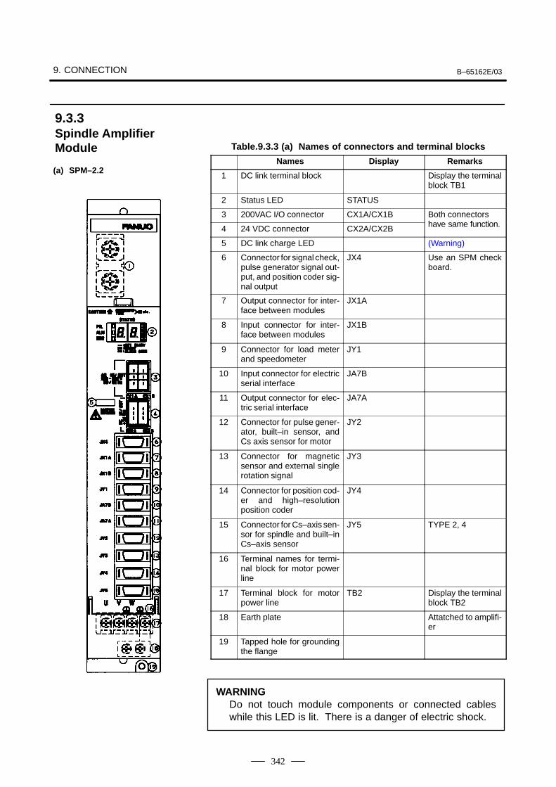
9. CONNECTION B–65162E/03
342
Table.9.3.3 (a) Names of connectors and terminal blocks
Names Display Remarks
1 DC link terminal block Display the terminalblock TB1
2 Status LED STATUS
3 200VAC I/O connector CX1A/CX1B Both connectorshave same function4 24 VDC connector CX2A/CX2B have same function.
5 DC link charge LED (Warning)
6 Connector for signal check,pulse generator signal out-put, and position coder sig-nal output
JX4 Use an SPM checkboard.
7 Output connector for inter-face between modules
JX1A
8 Input connector for inter-face between modules
JX1B
9 Connector for load meterand speedometer
JY1
10 Input connector for electricserial interface
JA7B
11 Output connector for elec-tric serial interface
JA7A
12 Connector for pulse gener-ator, built–in sensor, andCs axis sensor for motor
JY2
13 Connector for magneticsensor and external singlerotation signal
JY3
14 Connector for position cod-er and high–resolutionposition coder
JY4
15 Connector for Cs–axis sen-sor for spindle and built–inCs–axis sensor
JY5 TYPE 2, 4
16 Terminal names for termi-nal block for motor powerline
17 Terminal block for motorpower line
TB2 Display the terminalblock TB2
18 Earth plate Attatched to amplifi-er
19 Tapped hole for groundingthe flange
WARNINGDo not touch module components or connected cableswhile this LED is lit. There is a danger of electric shock.
9.3.3Spindle AmplifierModule
(a) SPM–2.2
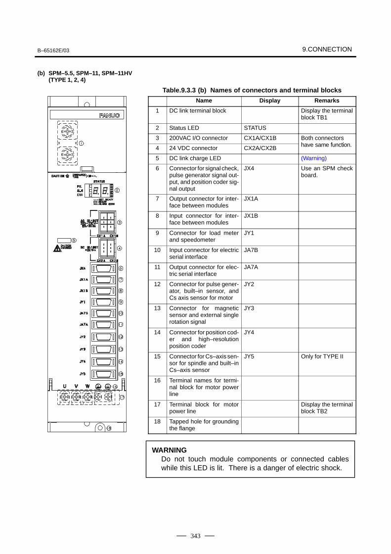
B–65162E/03 9.CONNECTION
343
Table.9.3.3 (b) Names of connectors and terminal blocks
Name Display Remarks
1 DC link terminal block Display the terminalblock TB1
2 Status LED STATUS
3 200VAC I/O connector CX1A/CX1B Both connectorshave same function4 24 VDC connector CX2A/CX2B have same function.
5 DC link charge LED (Warning)
6 Connector for signal check,pulse generator signal out-put, and position coder sig-nal output
JX4 Use an SPM checkboard.
7 Output connector for inter-face between modules
JX1A
8 Input connector for inter-face between modules
JX1B
9 Connector for load meterand speedometer
JY1
10 Input connector for electricserial interface
JA7B
11 Output connector for elec-tric serial interface
JA7A
12 Connector for pulse gener-ator, built–in sensor, andCs axis sensor for motor
JY2
13 Connector for magneticsensor and external singlerotation signal
JY3
14 Connector for position cod-er and high–resolutionposition coder
JY4
15 Connector for Cs–axis sen-sor for spindle and built–inCs–axis sensor
JY5 Only for TYPE II
16 Terminal names for termi-nal block for motor powerline
17 Terminal block for motorpower line
Display the terminalblock TB2
18 Tapped hole for groundingthe flange
WARNINGDo not touch module components or connected cableswhile this LED is lit. There is a danger of electric shock.
(b) SPM–5.5, SPM–11, SPM–11HV(TYPE 1, 2, 4)
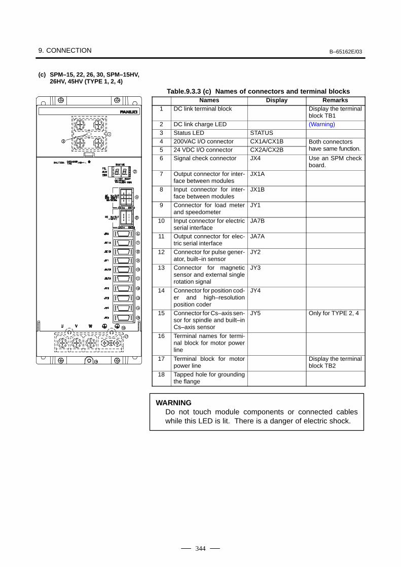
9. CONNECTION B–65162E/03
344
Table.9.3.3 (c) Names of connectors and terminal blocksNames Display Remarks
1 DC link terminal block Display the terminalblock TB1
2 DC link charge LED (Warning)3 Status LED STATUS4 200VAC I/O connector CX1A/CX1B Both connectors
h f i5 24 VDC I/O connector CX2A/CX2B have same function.
6 Signal check connector JX4 Use an SPM checkboard.
7 Output connector for inter-face between modules
JX1A
8 Input connector for inter-face between modules
JX1B
9 Connector for load meterand speedometer
JY1
10 Input connector for electricserial interface
JA7B
11 Output connector for elec-tric serial interface
JA7A
12 Connector for pulse gener-ator, built–in sensor
JY2
13 Connector for magneticsensor and external singlerotation signal
JY3
14 Connector for position cod-er and high–resolutionposition coder
JY4
15 Connector for Cs–axis sen-sor for spindle and built–inCs–axis sensor
JY5 Only for TYPE 2, 4
16 Terminal names for termi-nal block for motor powerline
17 Terminal block for motorpower line
Display the terminalblock TB2
18 Tapped hole for groundingthe flange
WARNINGDo not touch module components or connected cableswhile this LED is lit. There is a danger of electric shock.
(c) SPM–15, 22, 26, 30, SPM–15HV,26HV, 45HV (TYPE 1, 2, 4)
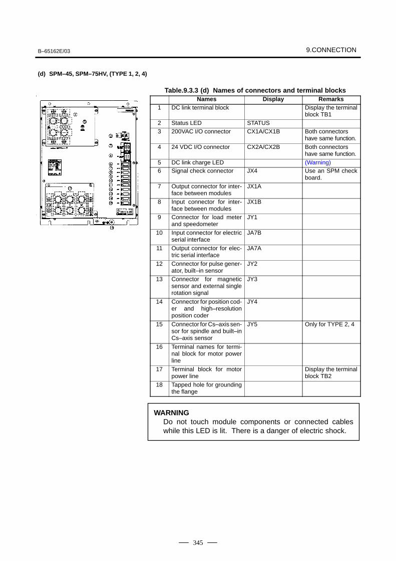
B–65162E/03 9.CONNECTION
345
Table.9.3.3 (d) Names of connectors and terminal blocksNames Display Remarks
1 DC link terminal block Display the terminalblock TB1
2 Status LED STATUS3 200VAC I/O connector CX1A/CX1B Both connectors
have same function.4 24 VDC I/O connector CX2A/CX2B Both connectors
have same function.5 DC link charge LED (Warning)6 Signal check connector JX4 Use an SPM check
board.7 Output connector for inter-
face between modulesJX1A
8 Input connector for inter-face between modules
JX1B
9 Connector for load meterand speedometer
JY1
10 Input connector for electricserial interface
JA7B
11 Output connector for elec-tric serial interface
JA7A
12 Connector for pulse gener-ator, built–in sensor
JY2
13 Connector for magneticsensor and external singlerotation signal
JY3
14 Connector for position cod-er and high–resolutionposition coder
JY4
15 Connector for Cs–axis sen-sor for spindle and built–inCs–axis sensor
JY5 Only for TYPE 2, 4
16 Terminal names for termi-nal block for motor powerline
17 Terminal block for motorpower line
Display the terminalblock TB2
18 Tapped hole for groundingthe flange
WARNINGDo not touch module components or connected cableswhile this LED is lit. There is a danger of electric shock.
(d) SPM–45, SPM–75HV, (TYPE 1, 2, 4)
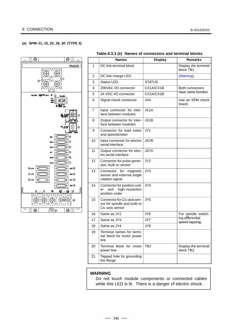
9. CONNECTION B–65162E/03
346
Table.9.3.3 (e) Names of connectors and terminal blocks
Names Display Remarks
1 DC link terminal block Display the terminalblock TB1
2 DC link charge LED (Warning)
3 Status LED STATUS
4 200VAC I/O connector CX1A/CX1B Both connectorshave same function5 24 VDC I/O connector CX2A/CX2B have same function.
6 Signal check connector JX4 Use an SPM checkboard.
7 Input connector for inter-face between modules
JX1A
8 Output connector for inter-face between modules
JX1B
9 Connector for load meterand speedometer
JY1
10 Input connector for electricserial interface
JA7B
11 Output connector for elec-tric serial interface
JA7A
12 Connector for pulse gener-ator, built–in sensor
JY2
13 Connector for magneticsensor and external singlerotation signal
JY3
14 Connector for position cod-er and high–resolutionposition coder
JY4
15 Connector for Cs–axis sen-sor for spindle and built–inCs–axis sensor
JY5
16 Same as JY2 JY6 For spindle switch-ing differential17 Same as JY3 JY7 ing differentialspeed tapping.
18 Same as JY4 JY8s eed ta ing.
19 Terminal names for termi-nal block for motor powerline
20 Terminal block for motorpower line
TB2 Display the terminalblock TB2
21 Tapped hole for groundingthe flange
WARNINGDo not touch module components or connected cableswhile this LED is lit. There is a danger of electric shock.
(e) SPM–11, 15, 22, 26, 30 (TYPE 3)
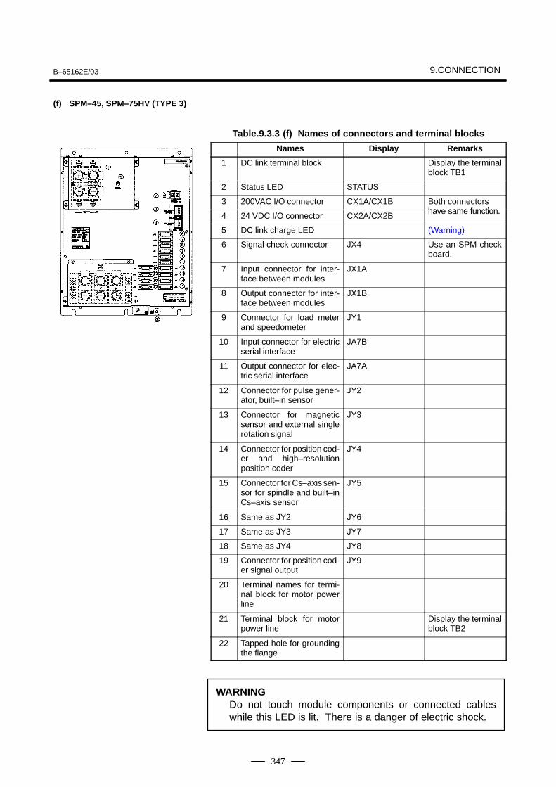
B–65162E/03 9.CONNECTION
347
Table.9.3.3 (f) Names of connectors and terminal blocks
Names Display Remarks
1 DC link terminal block Display the terminalblock TB1
2 Status LED STATUS
3 200VAC I/O connector CX1A/CX1B Both connectorshave same function4 24 VDC I/O connector CX2A/CX2B have same function.
5 DC link charge LED (Warning)
6 Signal check connector JX4 Use an SPM checkboard.
7 Input connector for inter-face between modules
JX1A
8 Output connector for inter-face between modules
JX1B
9 Connector for load meterand speedometer
JY1
10 Input connector for electricserial interface
JA7B
11 Output connector for elec-tric serial interface
JA7A
12 Connector for pulse gener-ator, built–in sensor
JY2
13 Connector for magneticsensor and external singlerotation signal
JY3
14 Connector for position cod-er and high–resolutionposition coder
JY4
15 Connector for Cs–axis sen-sor for spindle and built–inCs–axis sensor
JY5
16 Same as JY2 JY6
17 Same as JY3 JY7
18 Same as JY4 JY8
19 Connector for position cod-er signal output
JY9
20 Terminal names for termi-nal block for motor powerline
21 Terminal block for motorpower line
Display the terminalblock TB2
22 Tapped hole for groundingthe flange
WARNINGDo not touch module components or connected cableswhile this LED is lit. There is a danger of electric shock.
(f) SPM–45, SPM–75HV (TYPE 3)
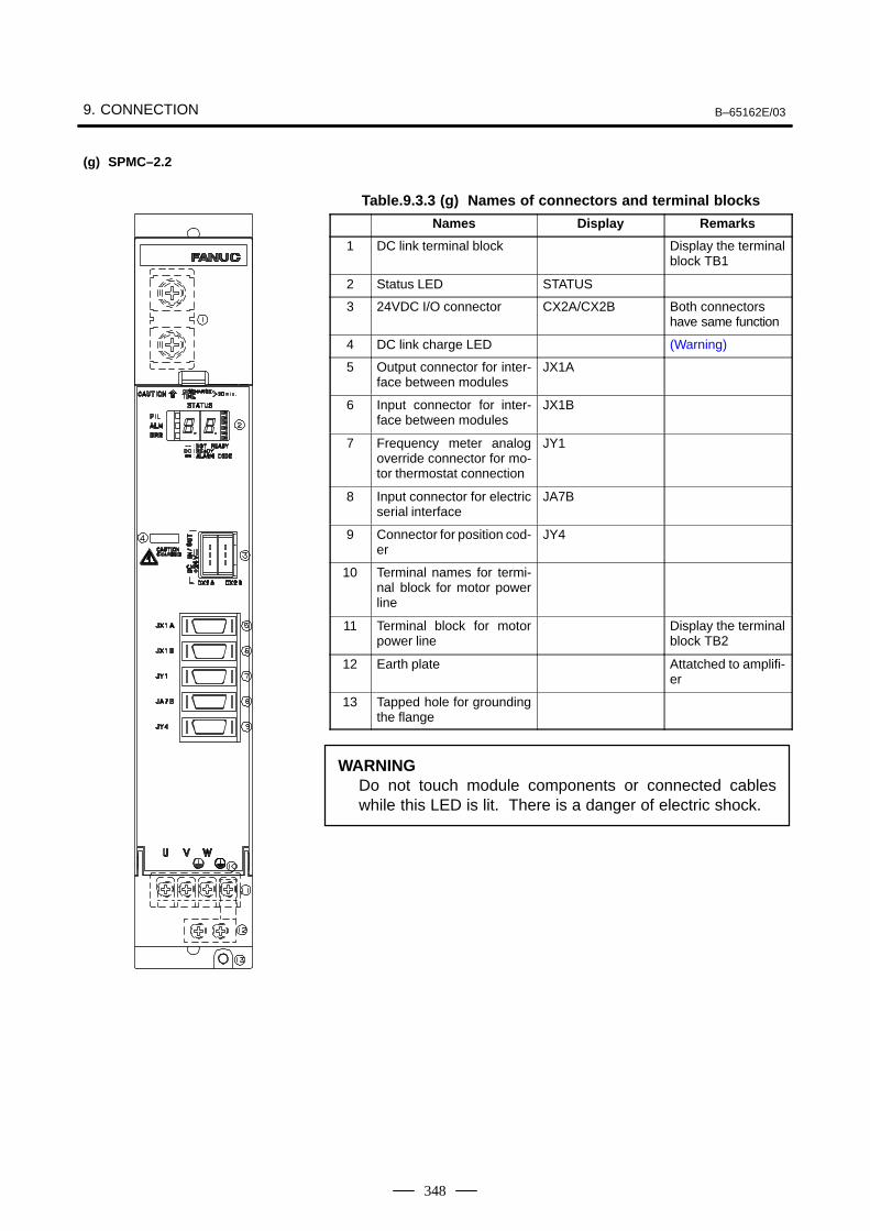
9. CONNECTION B–65162E/03
348
Table.9.3.3 (g) Names of connectors and terminal blocks
Names Display Remarks
1 DC link terminal block Display the terminalblock TB1
2 Status LED STATUS
3 24VDC I/O connector CX2A/CX2B Both connectorshave same function
4 DC link charge LED (Warning)
5 Output connector for inter-face between modules
JX1A
6 Input connector for inter-face between modules
JX1B
7 Frequency meter analogoverride connector for mo-tor thermostat connection
JY1
8 Input connector for electricserial interface
JA7B
9 Connector for position cod-er
JY4
10 Terminal names for termi-nal block for motor powerline
11 Terminal block for motorpower line
Display the terminalblock TB2
12 Earth plate Attatched to amplifi-er
13 Tapped hole for groundingthe flange
WARNINGDo not touch module components or connected cableswhile this LED is lit. There is a danger of electric shock.
(g) SPMC–2.2
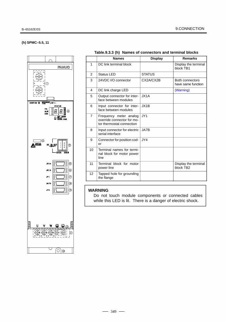
B–65162E/03 9.CONNECTION
349
Table.9.3.3 (h) Names of connectors and terminal blocks
Names Display Remarks
1 DC link terminal block Display the terminalblock TB1
2 Status LED STATUS
3 24VDC I/O connector CX2A/CX2B Both connectorshave same function
4 DC link charge LED (Warning)
5 Output connector for inter-face between modules
JX1A
6 Input connector for inter-face between modules
JX1B
7 Frequency meter analogoverride connector for mo-tor thermostat connection
JY1
8 Input connector for electricserial interface
JA7B
9 Connector for position cod-er
JY4
10 Terminal names for termi-nal block for motor powerline
11 Terminal block for motorpower line
Display the terminalblock TB2
12 Tapped hole for groundingthe flange
WARNINGDo not touch module components or connected cableswhile this LED is lit. There is a danger of electric shock.
(h) SPMC–5.5, 11
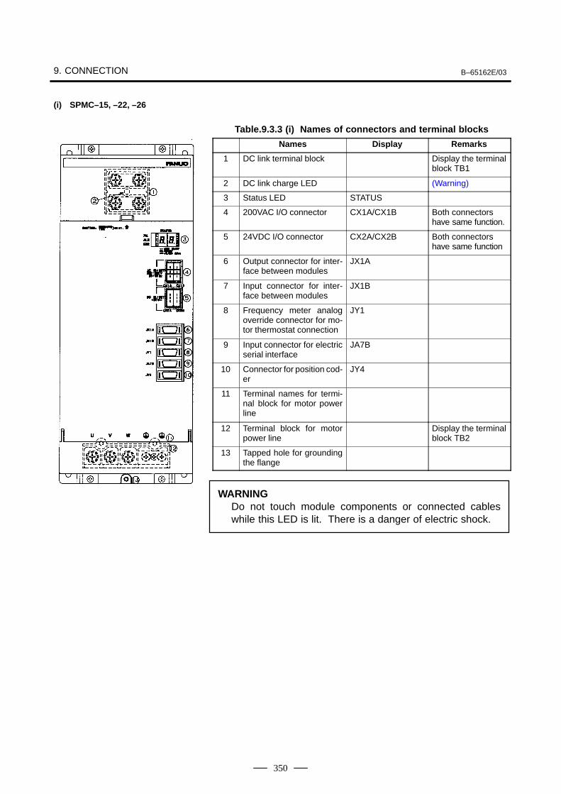
9. CONNECTION B–65162E/03
350
Table.9.3.3 (i) Names of connectors and terminal blocks
Names Display Remarks
1 DC link terminal block Display the terminalblock TB1
2 DC link charge LED (Warning)
3 Status LED STATUS
4 200VAC I/O connector CX1A/CX1B Both connectorshave same function.
5 24VDC I/O connector CX2A/CX2B Both connectorshave same function
6 Output connector for inter-face between modules
JX1A
7 Input connector for inter-face between modules
JX1B
8 Frequency meter analogoverride connector for mo-tor thermostat connection
JY1
9 Input connector for electricserial interface
JA7B
10 Connector for position cod-er
JY4
11 Terminal names for termi-nal block for motor powerline
12 Terminal block for motorpower line
Display the terminalblock TB2
13 Tapped hole for groundingthe flange
WARNINGDo not touch module components or connected cableswhile this LED is lit. There is a danger of electric shock.
(i) SPMC–15, –22, –26
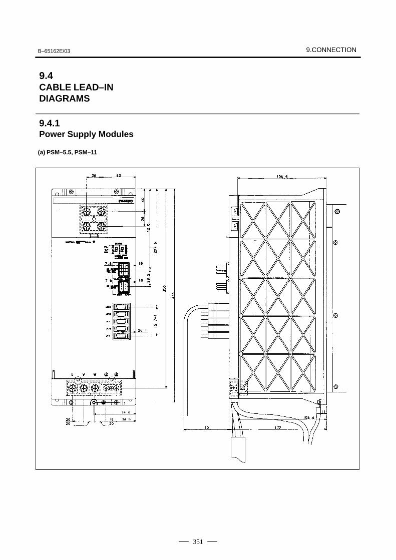
B–65162E/03 9.CONNECTION
351
9.4CABLE LEAD–IN DIAGRAMS
9.4.1Power Supply Modules
(a) PSM–5.5, PSM–11
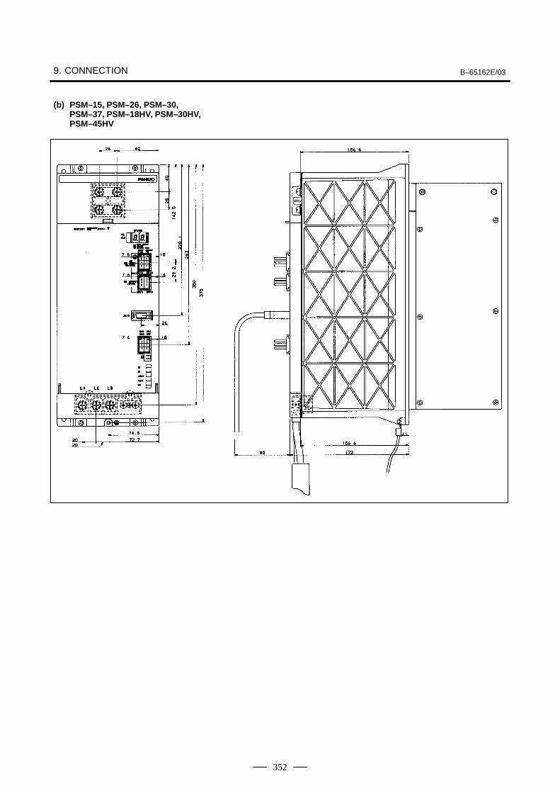
9. CONNECTION B–65162E/03
352
(b) PSM–15, PSM–26, PSM–30,PSM–37, PSM–18HV, PSM–30HV,PSM–45HV
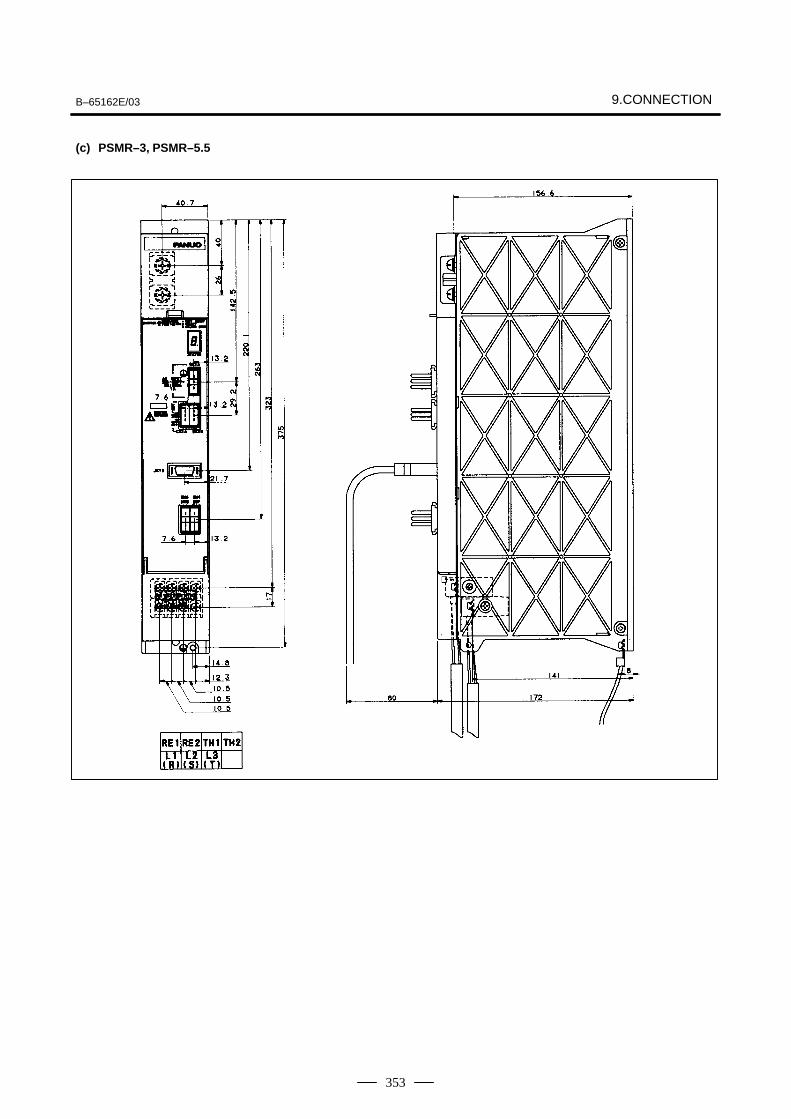
B–65162E/03 9.CONNECTION
353
(c) PSMR–3, PSMR–5.5
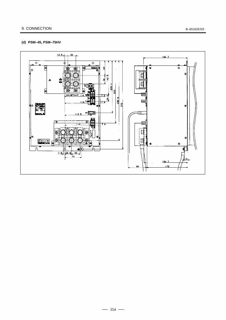
9. CONNECTION B–65162E/03
354
(d) PSM–45, PSM–75HV
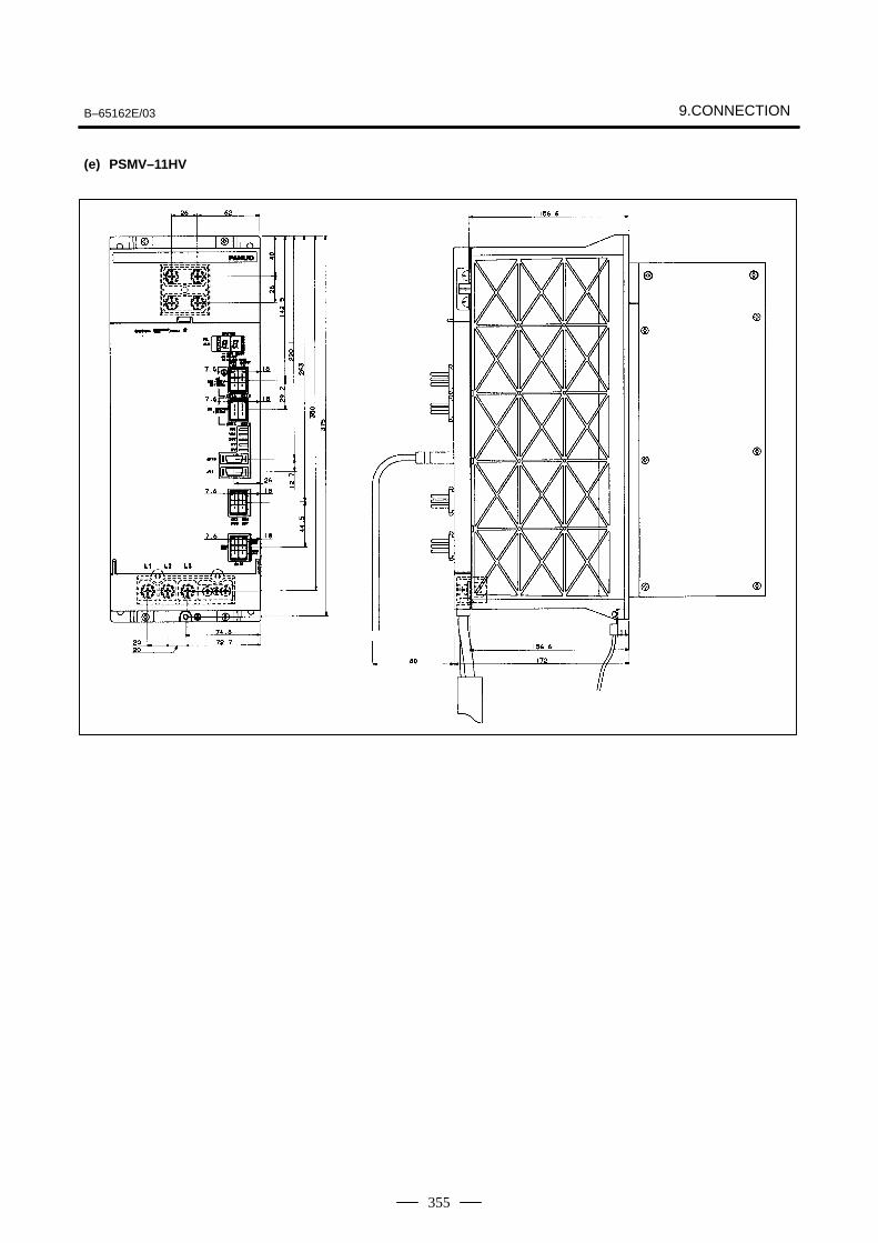
B–65162E/03 9.CONNECTION
355
(e) PSMV–11HV
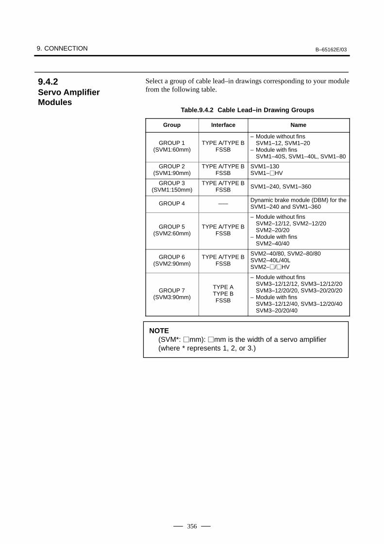
9. CONNECTION B–65162E/03
356
Select a group of cable lead–in drawings corresponding to your modulefrom the following table.
Table.9.4.2 Cable Lead–in Drawing Groups
Group Interface Name
GROUP 1(SVM1:60mm)
TYPE A/TYPE BFSSB
– Module without finsSVM1–12, SVM1–20
– Module with finsSVM1–40S, SVM1–40L, SVM1–80
GROUP 2(SVM1:90mm)
TYPE A/TYPE BFSSB
SVM1–130SVM1–HV
GROUP 3(SVM1:150mm)
TYPE A/TYPE BFSSB SVM1–240, SVM1–360
GROUP 4 –––Dynamic brake module (DBM) for theSVM1–240 and SVM1–360
GROUP 5(SVM2:60mm)
TYPE A/TYPE BFSSB
– Module without finsSVM2–12/12, SVM2–12/20 SVM2–20/20
– Module with finsSVM2–40/40
GROUP 6(SVM2:90mm)
TYPE A/TYPE BFSSB
SVM2–40/80, SVM2–80/80SVM2–40L/40LSVM2–/HV
GROUP 7(SVM3:90mm)
TYPE ATYPE BFSSB
– Module without finsSVM3–12/12/12, SVM3–12/12/20 SVM3–12/20/20, SVM3–20/20/20
– Module with finsSVM3–12/12/40, SVM3–12/20/40SVM3–20/20/40
NOTE(SVM*: mm): mm is the width of a servo amplifier (where * represents 1, 2, or 3.)
9.4.2Servo AmplifierModules
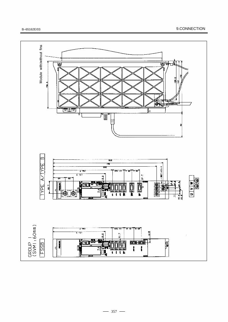
B–65162E/03 9.CONNECTION
357
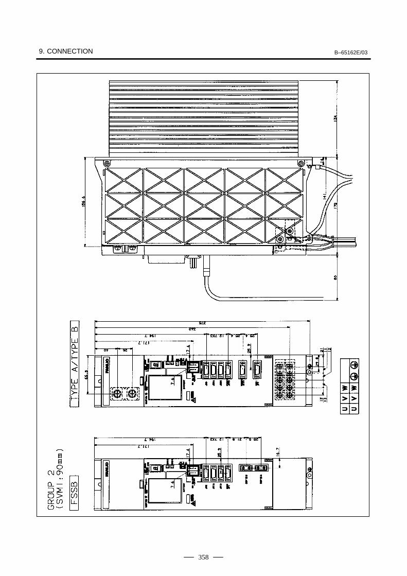
9. CONNECTION B–65162E/03
358
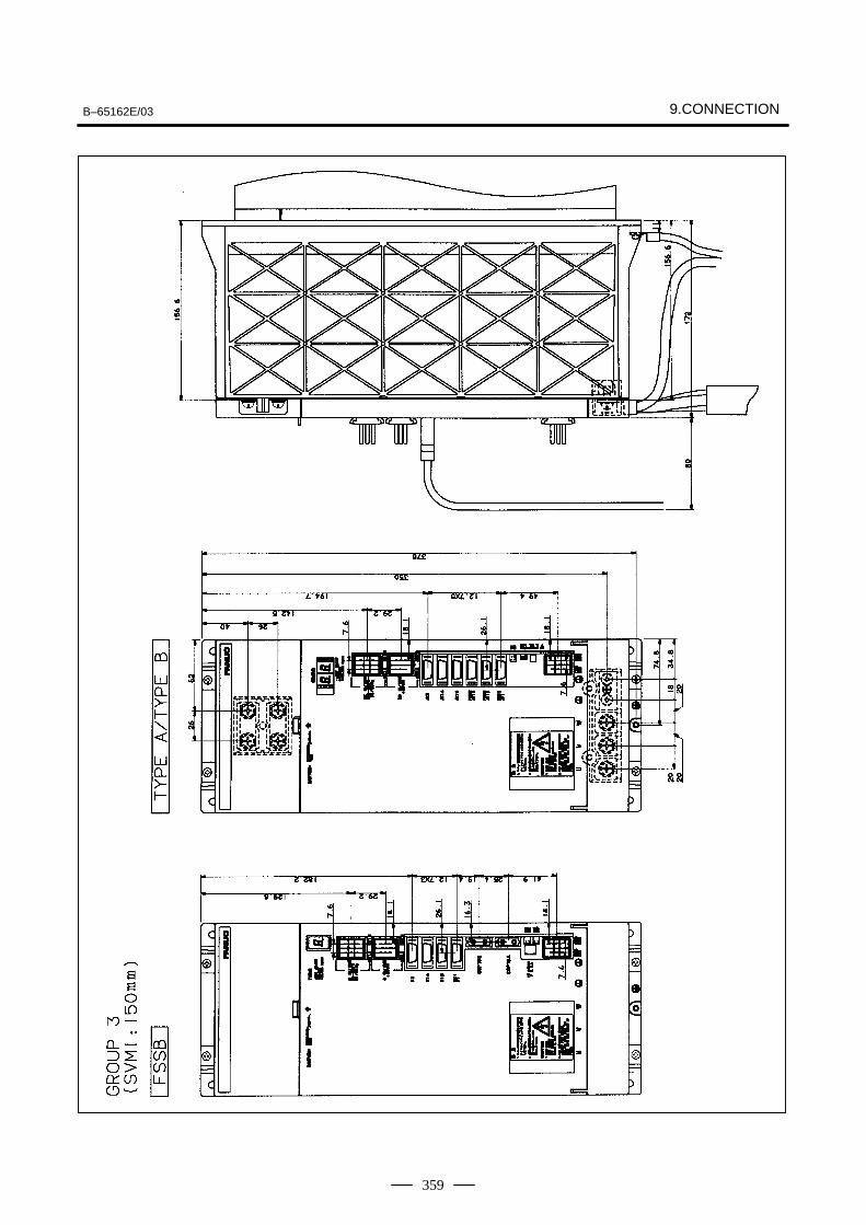
B–65162E/03 9.CONNECTION
359
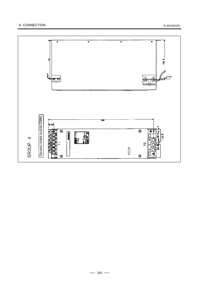
9. CONNECTION B–65162E/03
360
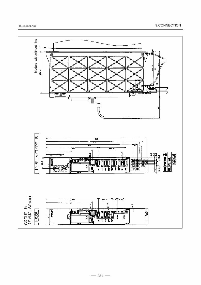
B–65162E/03 9.CONNECTION
361
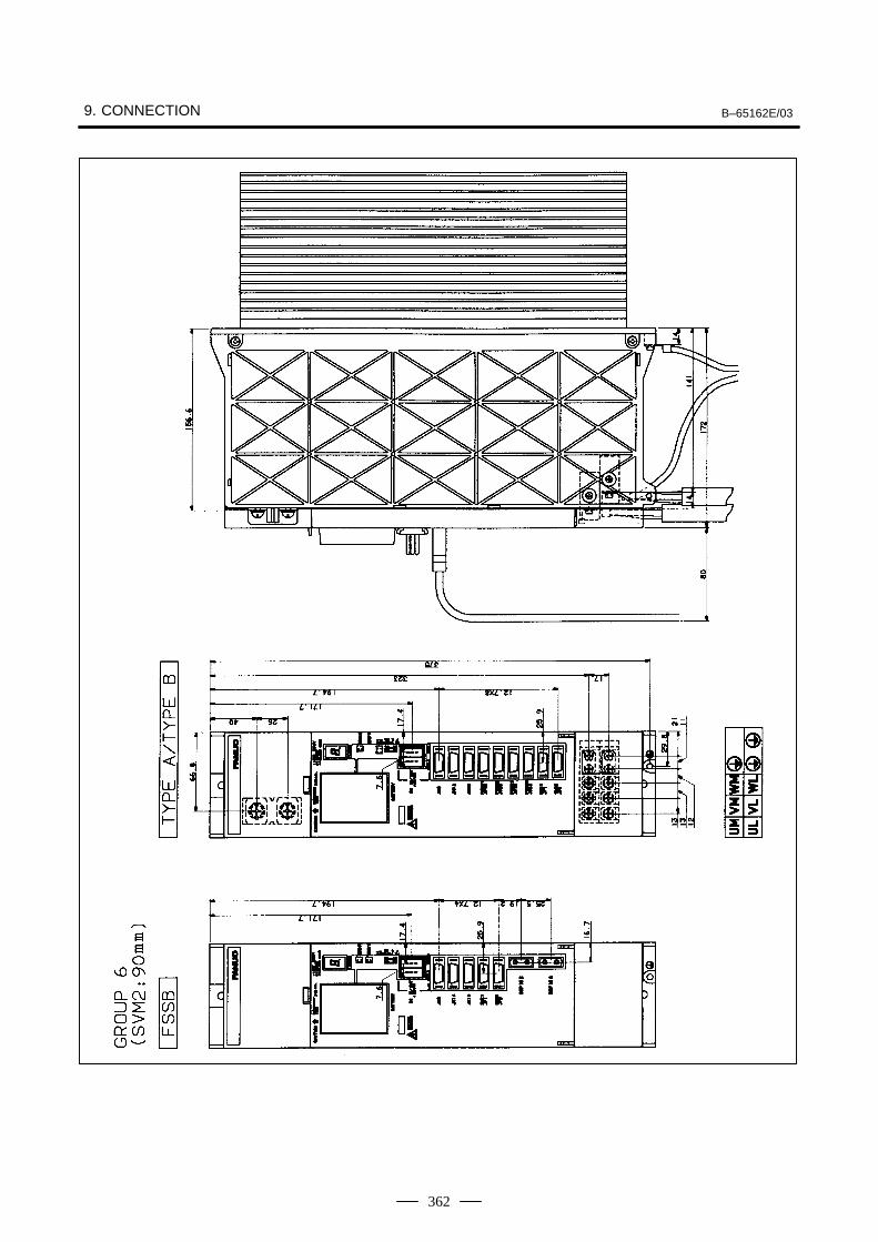
9. CONNECTION B–65162E/03
362
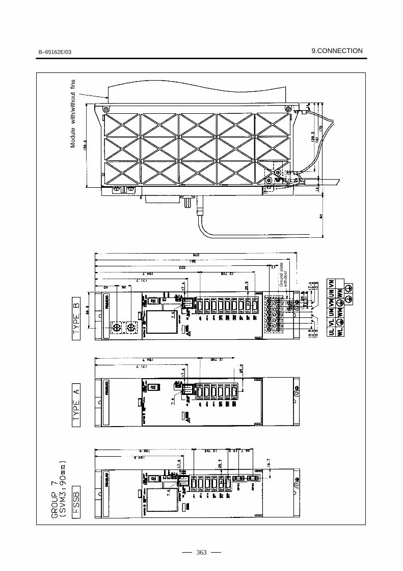
B–65162E/03 9.CONNECTION
363
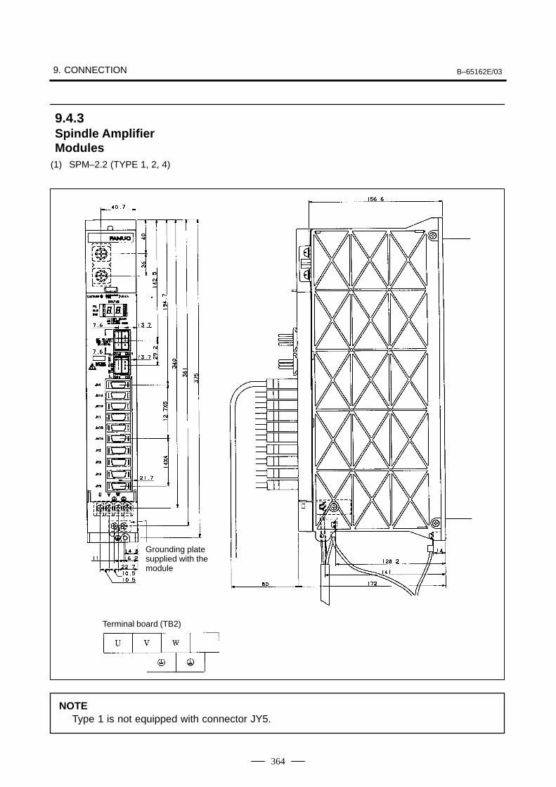
9. CONNECTION B–65162E/03
364
(1) SPM–2.2 (TYPE 1, 2, 4)
Grounding platesupplied with themodule
Terminal board (TB2)
NOTEType 1 is not equipped with connector JY5.
9.4.3Spindle AmplifierModules
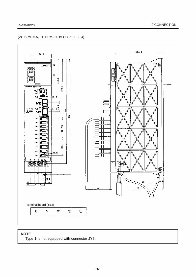
B–65162E/03 9.CONNECTION
365
(2) SPM–5.5, 11, SPM–11HV (TYPE 1, 2, 4)
Terminal board (TB2)
NOTEType 1 is not equipped with connector JY5.
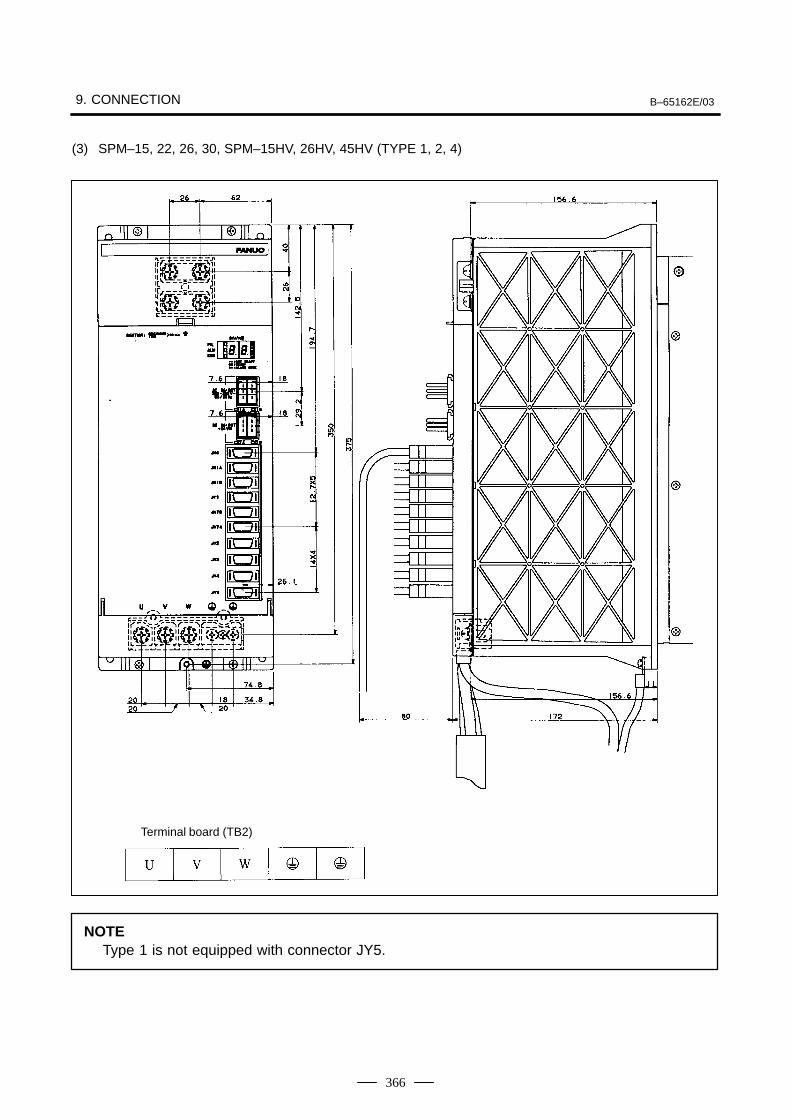
9. CONNECTION B–65162E/03
366
(3) SPM–15, 22, 26, 30, SPM–15HV, 26HV, 45HV (TYPE 1, 2, 4)
Terminal board (TB2)
NOTEType 1 is not equipped with connector JY5.
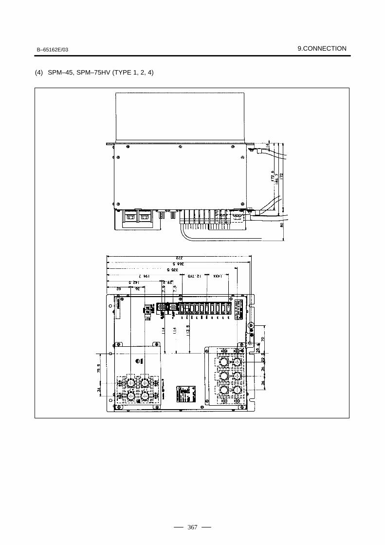
B–65162E/03 9.CONNECTION
367
(4) SPM–45, SPM–75HV (TYPE 1, 2, 4)
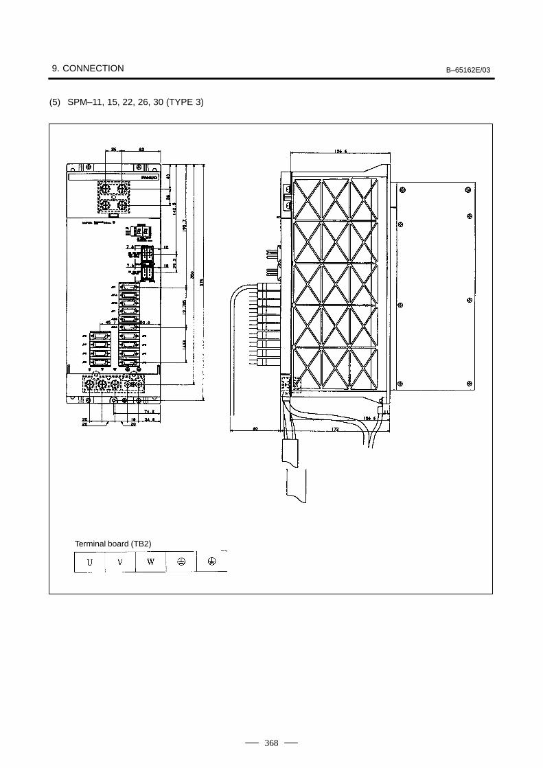
9. CONNECTION B–65162E/03
368
(5) SPM–11, 15, 22, 26, 30 (TYPE 3)
Terminal board (TB2)
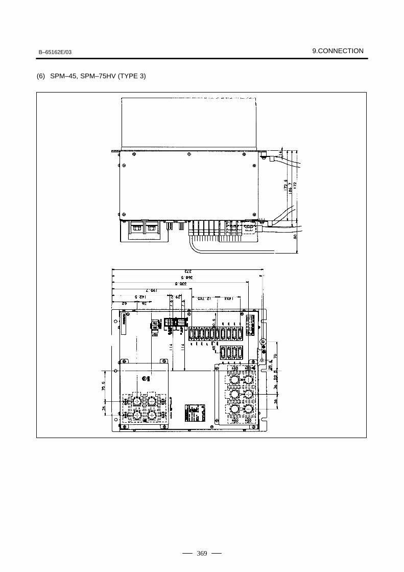
B–65162E/03 9.CONNECTION
369
(6) SPM–45, SPM–75HV (TYPE 3)
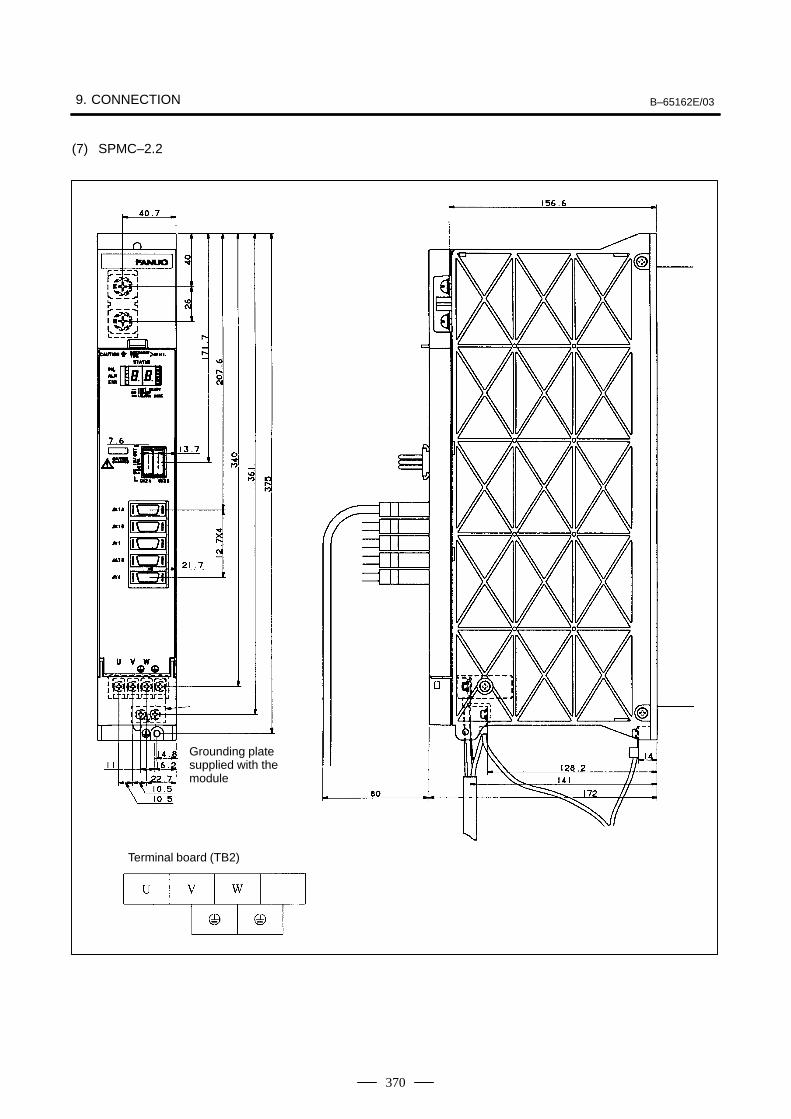
9. CONNECTION B–65162E/03
370
(7) SPMC–2.2
Grounding platesupplied with themodule
Terminal board (TB2)
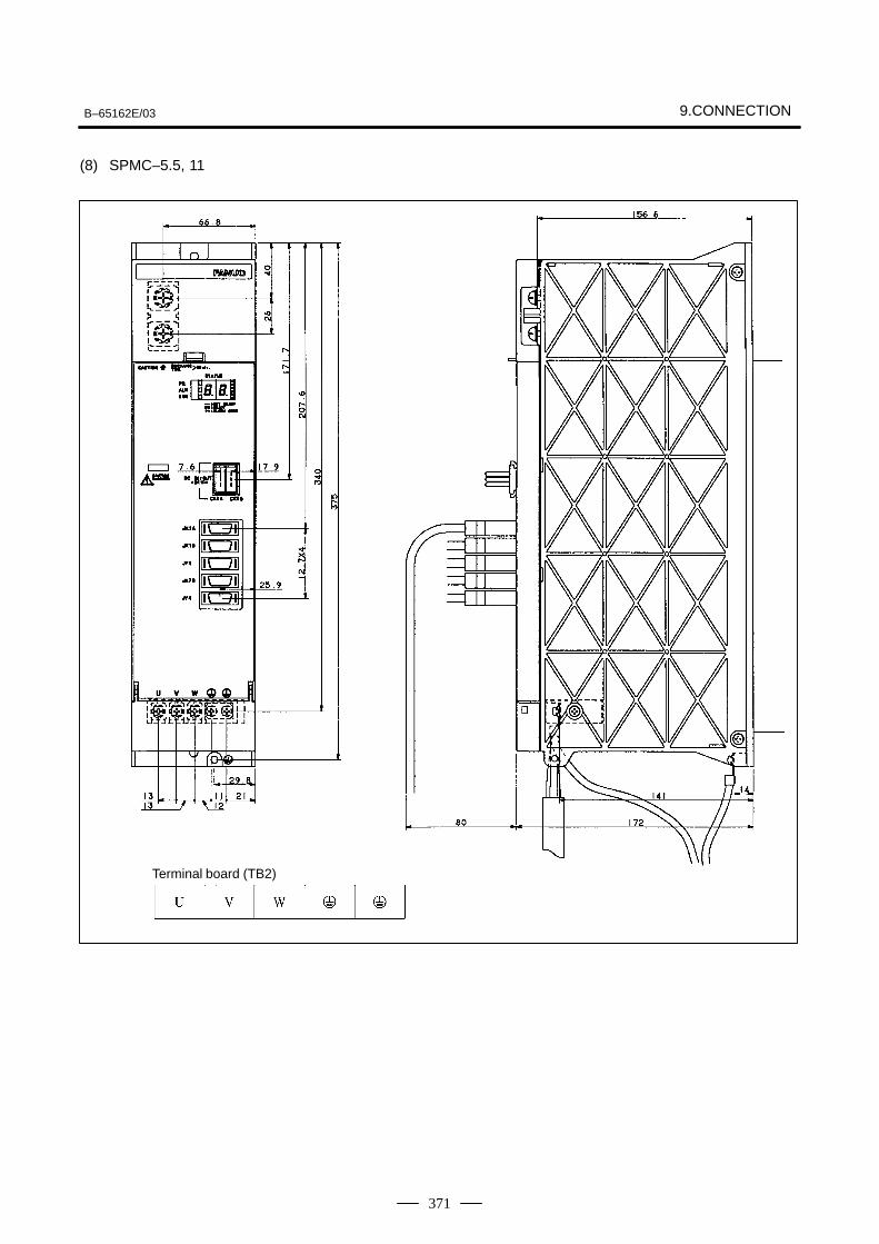
B–65162E/03 9.CONNECTION
371
(8) SPMC–5.5, 11
Terminal board (TB2)
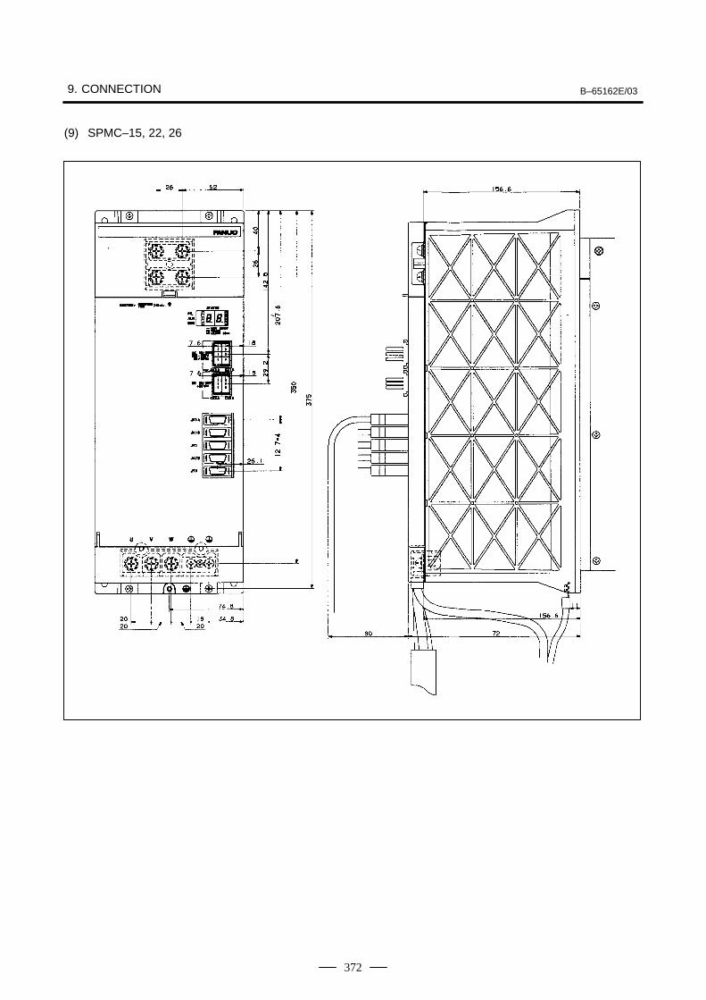
9. CONNECTION B–65162E/03
372
(9) SPMC–15, 22, 26

B–65162E/03 10. INTERFACE SIGNALS
373
10
10. INTERFACE SIGNALS B–65162E/03
374
The α series servo amplifier has a terminal for the emergency stop signalon the power supply module (connector: CX4). Always use theemergency stop signal.
When the contact is closed (on), the spindle motors and servo motorscan operate. When the contact is open (off), the external magneticcontactor is turned off, preventing operation of the spindle motors andservo motors.
When the contact is opened (turned off) while a motor is rotating, aspindle motor will decelerate naturally and stop, while a servo motorwill stop by the application of its dynamic brake.
The contact input signal has the following specifications:
External contact capacity: 30 VDC or higher, 100 mA or higher
Significant levels for contactless input (voltage between inputterminals)
Low (logical 0) : 2 V or lowerHigh (logical 1) : 20 V or higher
10.1EMERGENCY STOPSIGNAL (*ESP)– CONTACT INPUT SIGNAL –
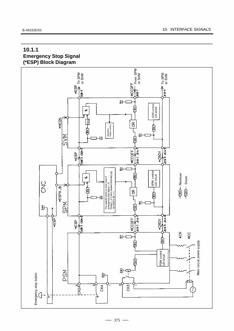
B–65162E/03 10. INTERFACE SIGNALS
375
10.1.1Emergency Stop Signal(*ESP) Block Diagram
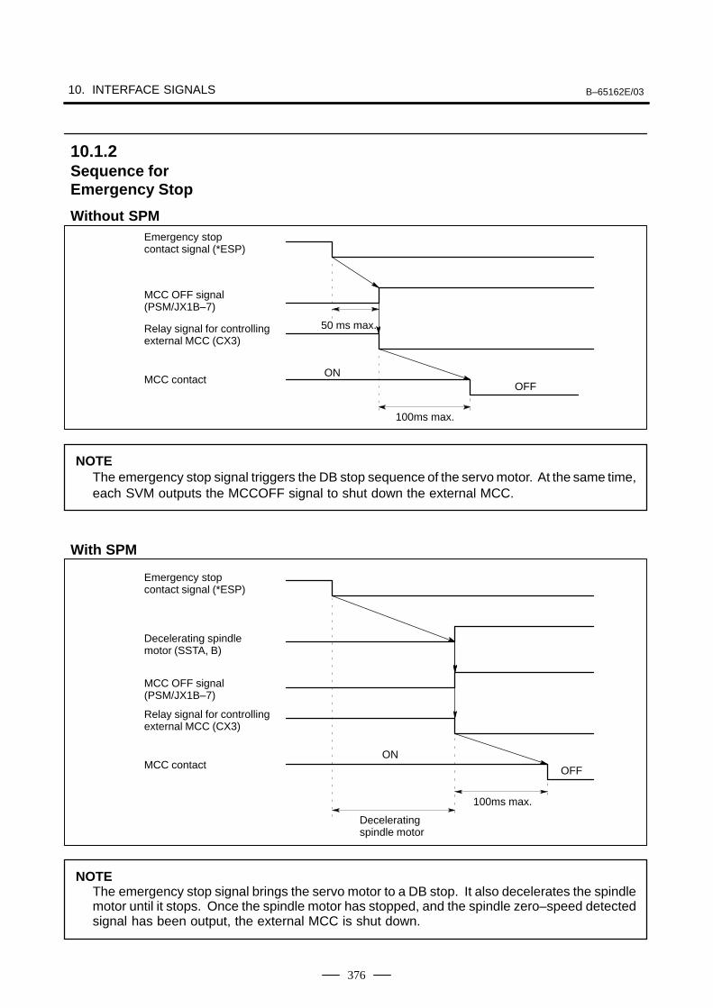
10. INTERFACE SIGNALS B–65162E/03
376
Emergency stop contact signal (*ESP)
MCC OFF signal(PSM/JX1B–7)
Relay signal for controllingexternal MCC (CX3)
MCC contact
50 ms max.
OFFON
100ms max.
NOTEThe emergency stop signal triggers the DB stop sequence of the servo motor. At the same time,each SVM outputs the MCCOFF signal to shut down the external MCC.
Emergency stop contact signal (*ESP)
Decelerating spindlemotor (SSTA, B)
Relay signal for controllingexternal MCC (CX3)
MCC contact OFF
ON
100ms max.
Deceleratingspindle motor
MCC OFF signal(PSM/JX1B–7)
NOTEThe emergency stop signal brings the servo motor to a DB stop. It also decelerates the spindlemotor until it stops. Once the spindle motor has stopped, and the spindle zero–speed detectedsignal has been output, the external MCC is shut down.
10.1.2Sequence forEmergency Stop
Without SPM
With SPM
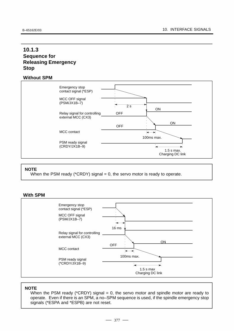
B–65162E/03 10. INTERFACE SIGNALS
377
Emergency stop contact signal (*ESP)
MCC OFF signal(PSM/JX1B–7)
Relay signal for controllingexternal MCC (CX3)
MCC contact
PSM ready signal(CRDY/JX1B–9)
2 s
OFFON
100ms max.
1.5 s max.Charging DC link
OFFON
NOTEWhen the PSM ready (*CRDY) signal = 0, the servo motor is ready to operate.
Emergency stop contact signal (*ESP)
MCC OFF signal(PSM/JX1B–7)
Relay signal for controllingexternal MCC (CX3)
MCC contact
PSM ready signal(*CRDY/JX1B–9)
16 ms
OFFON
100ms max.
1.5 s maxCharging DC link
NOTEWhen the PSM ready (*CRDY) signal = 0, the servo motor and spindle motor are ready tooperate. Even if there is an SPM, a no–SPM sequence is used, if the spindle emergency stopsignals (*ESPA and *ESPB) are not reset.
10.1.3Sequence forReleasing EmergencyStop
Without SPM
With SPM

10. INTERFACE SIGNALS B–65162E/03
378
10.2SPINDLE CONTROL SIGNALS (α series spindle)
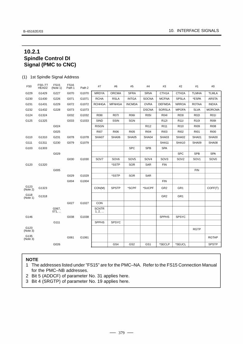
B–65162E/03 10. INTERFACE SIGNALS
379
(1) 1st Spindle Signal Address
FS0 FS0–TTHEAD2
FS15(Note 1)
FS16Path 1 Path 2 #7 #6 #5 #4 #3 #2 #1 #0
G229 G1429 G227 G070 G1070 MRDYA ORCMA SFRA SRVA CTH1A CTH2A TLMHA TLMLA
G230 G1430 G226 G071 G1071 RCHA RSLA INTGA SOCNA MCFNA SPSLA *ESPA ARSTA
G231 G1431 G229 G072 G1072 RCHHGA MFNHGA INCMDA OVRA DEFMDA NRROA ROTAA INDXA
G232 G1432 G228 G073 G1073 DSCNA SORSLA MPOFA SLVA MORCMA
G124 G1324 G032 G1032 R08I R07I R06I R05I R04I R03I R02I R01I
G125 G1325 G033 G1033 SIND SSIN SGN R12I R11I R10I R09I
G024 RISGN RI12 RI11 RI10 RI09 RI08
G025 RI07 RI06 RI05 RI04 RI03 RI02 RI01 RI00
G110 G1310 G231 G078 G1078 SHA07 SHA06 SHA05 SHA04 SHA03 SHA02 SHA01 SHA00
G111 G1311 G230 G079 G1079 SHA11 SHA10 SHA09 SHA08
G103 G1303 SPC SPB SPA
G029 SPC SPB SPA
G030 G1030 SOV7 SOV6 SOV5 SOV4 SOV3 SOV2 SOV1 SOV0
G120 G1320 *SSTP SOR SAR FIN
G005 FIN
G029 G1029 *SSTP SOR SAR
G004 G1004 FIN
G123(Note 2) G1323 CON(M) SPSTP *SCPF *SUCPF GR2 GR1 COFF(T)
G118(Note 1) G1318 GR2 GR1
G027 G1027 CON
G067,071, ...
SCNTR1, 2, ...
G146 G038 G1038 SPPHS SPSYC
G111 SPPHS SPSYC
G123(Note 3) RGTP
G135(Note 3) G061 G1061 RGTAP
G026 GS4 GS2 GS1 *SECLP *SEUCL SPSTP
NOTE1 The addresses listed under ”FS15” are for the PMC–NA. Refer to the FS15 Connection Manual
for the PMC–NB addresses.2 Bit 5 (ADDCF) of parameter No. 31 applies here.3 Bit 4 (SRGTP) of parameter No. 19 applies here.
10.2.1Spindle Control DISignal (PMC to CNC)
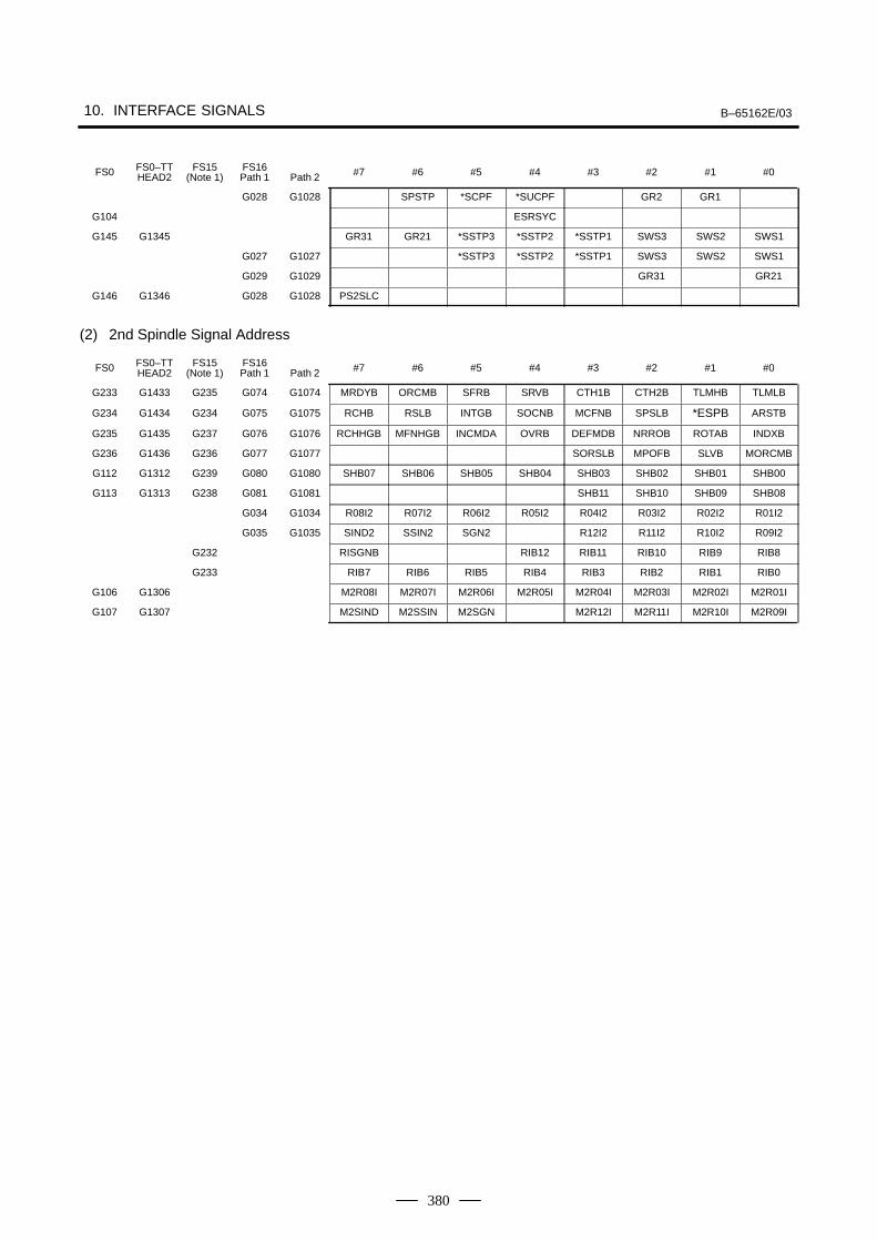
10. INTERFACE SIGNALS B–65162E/03
380
FS0 FS0–TTHEAD2
FS15(Note 1)
FS16Path 1 Path 2 #7 #6 #5 #4 #3 #2 #1 #0
G028 G1028 SPSTP *SCPF *SUCPF GR2 GR1
G104 ESRSYC
G145 G1345 GR31 GR21 *SSTP3 *SSTP2 *SSTP1 SWS3 SWS2 SWS1
G027 G1027 *SSTP3 *SSTP2 *SSTP1 SWS3 SWS2 SWS1
G029 G1029 GR31 GR21
G146 G1346 G028 G1028 PS2SLC
(2) 2nd Spindle Signal Address
FS0 FS0–TTHEAD2
FS15(Note 1)
FS16Path 1 Path 2 #7 #6 #5 #4 #3 #2 #1 #0
G233 G1433 G235 G074 G1074 MRDYB ORCMB SFRB SRVB CTH1B CTH2B TLMHB TLMLB
G234 G1434 G234 G075 G1075 RCHB RSLB INTGB SOCNB MCFNB SPSLB *ESPB ARSTB
G235 G1435 G237 G076 G1076 RCHHGB MFNHGB INCMDA OVRB DEFMDB NRROB ROTAB INDXB
G236 G1436 G236 G077 G1077 SORSLB MPOFB SLVB MORCMB
G112 G1312 G239 G080 G1080 SHB07 SHB06 SHB05 SHB04 SHB03 SHB02 SHB01 SHB00
G113 G1313 G238 G081 G1081 SHB11 SHB10 SHB09 SHB08
G034 G1034 R08I2 R07I2 R06I2 R05I2 R04I2 R03I2 R02I2 R01I2
G035 G1035 SIND2 SSIN2 SGN2 R12I2 R11I2 R10I2 R09I2
G232 RISGNB RIB12 RIB11 RIB10 RIB9 RIB8
G233 RIB7 RIB6 RIB5 RIB4 RIB3 RIB2 RIB1 RIB0
G106 G1306 M2R08I M2R07I M2R06I M2R05I M2R04I M2R03I M2R02I M2R01I
G107 G1307 M2SIND M2SSIN M2SGN M2R12I M2R11I M2R10I M2R09I
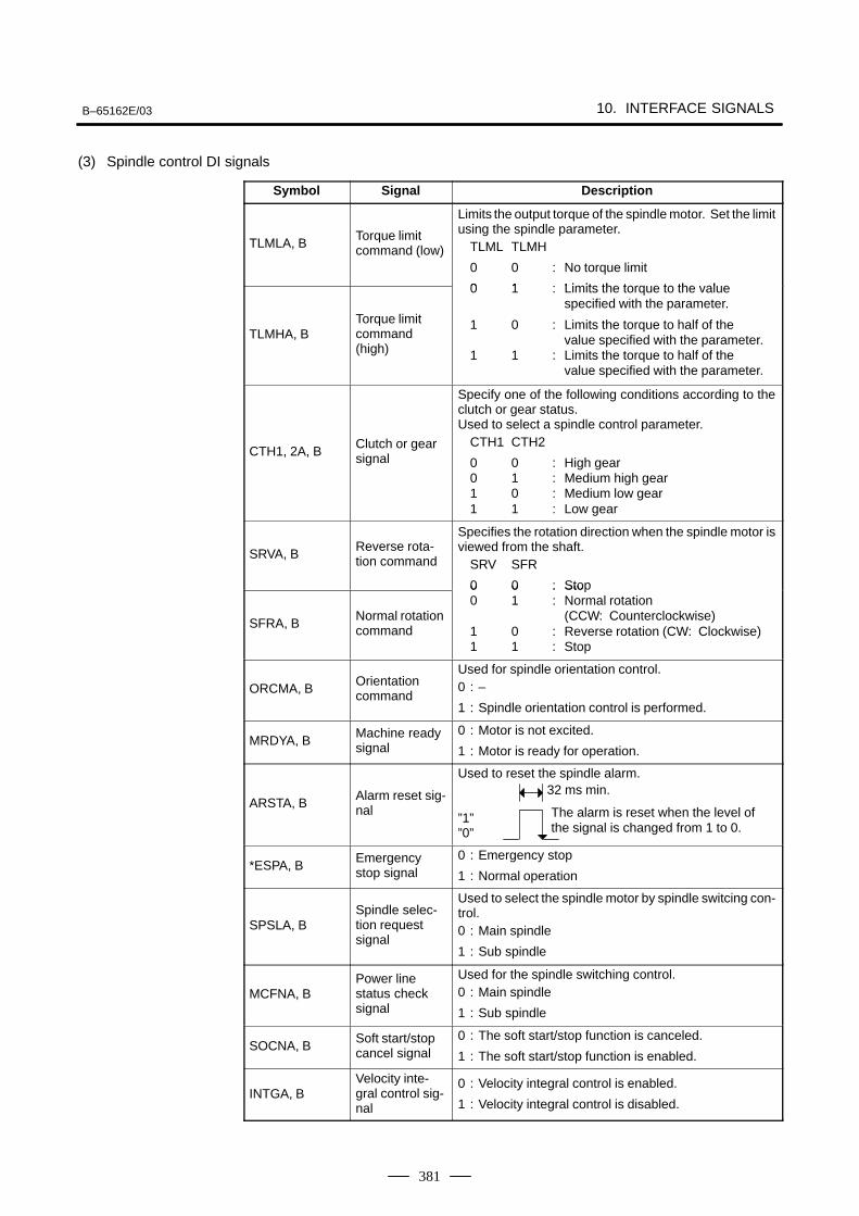
B–65162E/03 10. INTERFACE SIGNALS
381
(3) Spindle control DI signals
Symbol Signal Description
TLMLA, BTorque limitcommand (low)
Limits the output torque of the spindle motor. Set the limitusing the spindle parameter.
TLML TLMH
0 0 : No torque limit
0 1 : Limits the torque to the value
TLMHA, BTorque limitcommand(high)
0 1 : Limits the torque to the value specified with the parameter.
1 0 : Limits the torque to half of thevalue specified with the parameter.
1 1 : Limits the torque to half of the value specified with the parameter.
CTH1, 2A, BClutch or gearsignal
Specify one of the following conditions according to theclutch or gear status.Used to select a spindle control parameter.
CTH1 CTH2
0 0 : High gear0 1 : Medium high gear1 0 : Medium low gear1 1 : Low gear
SRVA, BReverse rota-tion command
Specifies the rotation direction when the spindle motor isviewed from the shaft.
SRV SFR
0 0 : Stop
SFRA, BNormal rotationcommand
0 0 : Sto0 1 : Normal rotation
(CCW: Counterclockwise)1 0 : Reverse rotation (CW: Clockwise)1 1 : Stop
ORCMA, BOrientationcommand
Used for spindle orientation control.0 : –
1 : Spindle orientation control is performed.
MRDYA, BMachine readysignal
0 : Motor is not excited.
1 : Motor is ready for operation.
ARSTA, BAlarm reset sig-nal
Used to reset the spindle alarm.
”1””0”
*ESPA, BEmergencystop signal
0 : Emergency stop
1 : Normal operation
SPSLA, BSpindle selec-tion requestsignal
Used to select the spindle motor by spindle switcing con-trol.0 : Main spindle
1 : Sub spindle
MCFNA, BPower line status checksignal
Used for the spindle switching control.0 : Main spindle
1 : Sub spindle
SOCNA, BSoft start/stopcancel signal
0 : The soft start/stop function is canceled.
1 : The soft start/stop function is enabled.
INTGA, BVelocity inte-gral control sig-nal
0 : Velocity integral control is enabled.
1 : Velocity integral control is disabled.
The alarm is reset when the level ofthe signal is changed from 1 to 0.
32 ms min.
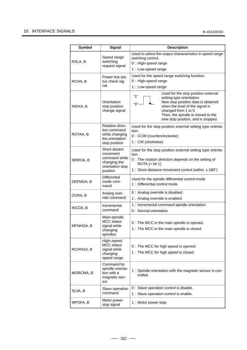
10. INTERFACE SIGNALS B–65162E/03
382
Symbol DescriptionSignal
RSLA, BSpeed rangeswitchingrequest signal
Used to select the output characteristics in speed rangeswiching control.0 : High-speed range
1 : Low-speed range
RCHA, BPower line sta-tus check sig-nal
Used for the speed range switching function.0 : High-speed range
1 : Low-speed range
INDXA, BOrientationstop positionchange signal
Used for the stop position external setting type orientation.New stop position data is obtained when the level of the signal is changed from 1 to 0.Then, the spindle is moved to the new stop position, and is stopped.
ROTAA, B
Rotation direc-tion commandwhile changingthe orientationstop position
Used for the stop position external setting type orienta-tion.0 : CCW (counterclockwise)
1 : CW (clockwise)
NRROA, B
Short-distantmovementcommand whilechanging theorientation stopposition
Used for the stop position external setting type orienta-tion.0 : The rotation direction depends on the setting of
ROTA (= bit 1)
1 : Short-distance movement control (within 180°)
DEFMDA, BDifferentialmode com-mand
Used for the spindle differential control mode1 : Differential control mode
OVRA, BAnalog over-ride command
0 : Analog override is disabled.
1 : Analog override is enabled.
INCDA, BIncrementalcommand
1 : Incremental command spindle orientation
0 : Normal orientation
MFNHGA, B
Main-spindleMCC statussignal whilechangingspindles
0 : The MCC in the main spindle is opened.
1 : The MCC in the main spindle is closed.
RCHHGA, B
High–speedMCC statussignal whilechangingspeed range
0 : The MCC for high speed is opened.
1 : The MCC for high speed is closed.
MORCMA, B
Command forspindle orienta-tion with amagnetic sen-sor
1 : Spindle orientation with the magnetic sensor is con-trolled.
SLVA, BSlave operationcommand
0 : Slave operation control is disable.
1 : Slave operation control is enable.
MPOFA, BMotor powerstop signal 1 : Motor power stop
”1”
”0”
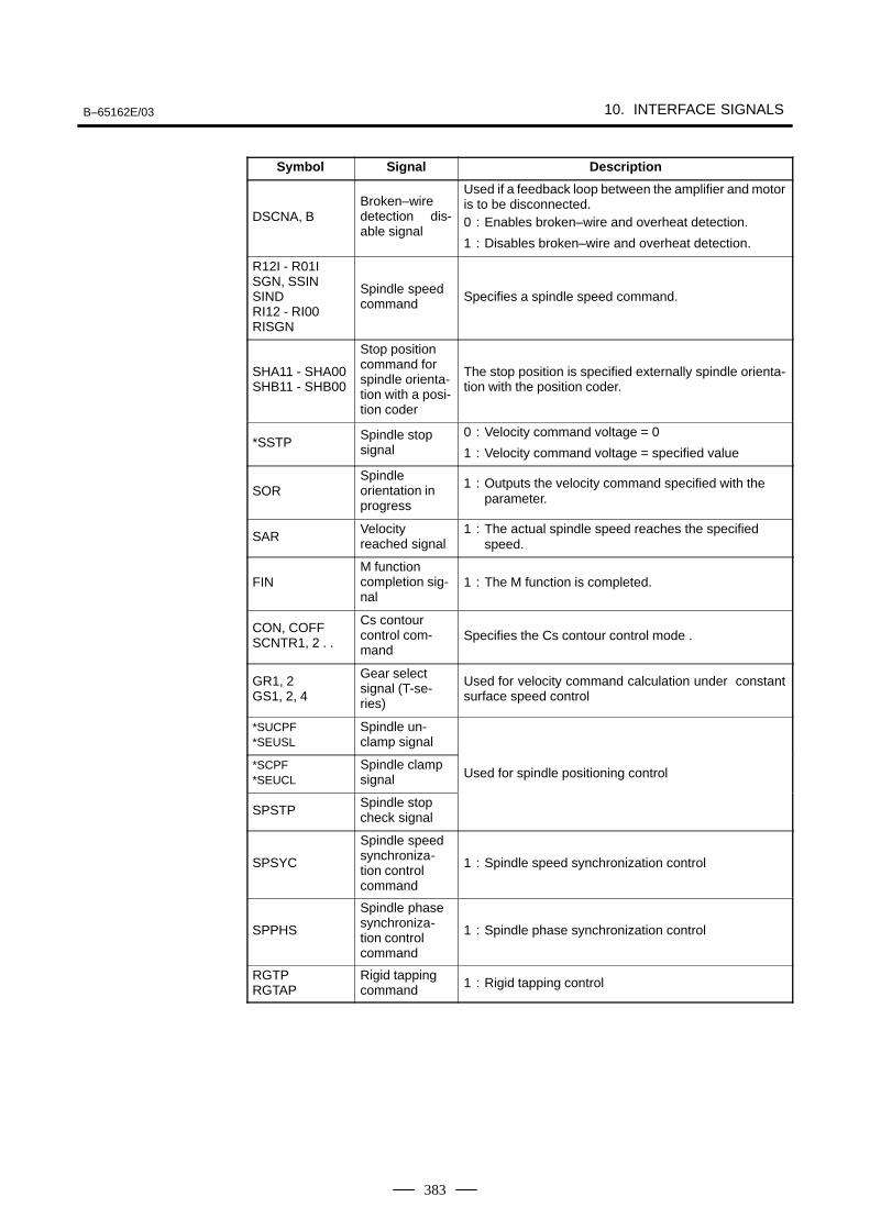
B–65162E/03 10. INTERFACE SIGNALS
383
Symbol DescriptionSignal
DSCNA, BBroken–wiredetection dis-able signal
Used if a feedback loop between the amplifier and motoris to be disconnected.0 : Enables broken–wire and overheat detection.
1 : Disables broken–wire and overheat detection.
R12I - R01I SGN, SSIN SINDRI12 - RI00 RISGN
Spindle speedcommand Specifies a spindle speed command.
SHA11 - SHA00SHB11 - SHB00
Stop positioncommand forspindle orienta-tion with a posi-tion coder
The stop position is specified externally spindle orienta-tion with the position coder.
*SSTPSpindle stopsignal
0 : Velocity command voltage = 0
1 : Velocity command voltage = specified value
SORSpindleorientation inprogress
1 : Outputs the velocity command specified with theparameter.
SARVelocityreached signal
1 : The actual spindle speed reaches the specifiedspeed.
FINM functioncompletion sig-nal
1 : The M function is completed.
CON, COFF SCNTR1, 2 . .
Cs contourcontrol com-mand
Specifies the Cs contour control mode .
GR1, 2GS1, 2, 4
Gear selectsignal (T-se-ries)
Used for velocity command calculation under constantsurface speed control
*SUCPF*SEUSL
Spindle un-clamp signal
*SCPF*SEUCL
Spindle clampsignal Used for spindle positioning control
SPSTPSpindle stopcheck signal
SPSYC
Spindle speedsynchroniza-tion controlcommand
1 : Spindle speed synchronization control
SPPHS
Spindle phasesynchroniza-tion controlcommand
1 : Spindle phase synchronization control
RGTPRGTAP
Rigid tappingcommand 1 : Rigid tapping control

10. INTERFACE SIGNALS B–65162E/03
384
(1) 1st Spindle Signal Address
FS0 FS0–TTHEAD2
FS15(Note 1)
FS16Path 1 Path 2 #7 #6 #5 #4 #3 #2 #1 #0
F281 F1481 F229 F045 F1045 ORARA TLMA LDT2A LDT1A SARA SDTA SSTA ALMA
F282 F1482 F228 F046 F1046 MOAR2A MOAR1A POAR2A SLVSA RCFNA RCHPA CFINA CHPA
F283 F1483 F231 F047 F1047 EXOFA SORENA MSOVRA INCSTA PC1DTA
F172 F1372 F036 F1036 R08O R07O R06O R05O R04O R03O R02O R01O
F173 F1373 F037 F1037 R12O R11O R10O R09O
F010(F006)
(Note 2)
RO15 RO14 RO13 RO12 RO11 RO10 RO09 RO08
F001(F001)
RO07 RO06 RO05 RO04 RO03 RO02 RO01 RO00
F150 F1350 F007 F1007 SF MF
SF MF
F149 F1349 F001 F1001 ENB
F164 F1364 F038 F1038 ENB3 ENB2 SCLP SUCLP
SPCO SPBO SPAO SPAL SSLP SUCLP
F154 F1354 F035 F1035 SPAL
F152 F1352 F034 F1034 GR30 GR20 GR10
F001 CSS
F002 F1002 CSS
F178 F044 F1044 SYCAL FSPPH FSPSY FSCSL
F67, 71,...
MCNTR1,2, ...
F111 MSPPHS MSPSYC SPSYAL
F040 RTAP
F020 F025 F1025 S31 S30 S29 S28 S27 S26 S25 S24
F021 F024 F1024 S23 S22 S21 S20 S19 S18 S17 S16
F022 F023 F1023 S15 S14 S13 S12 S11 S10 S09 S08
F023 F022 F1022 S07 S06 S05 S04 S03 S02 S01 S00
F012 F041 F1041 AR15 AR14 AR13 AR12 AR11 AR10 AR09 AR08
F013 F040 F1040 AR07 AR06 AR05 AR04 AR03 AR02 AR01 AR00
F232 SLDM15 SLDM14 SLDM13 SLDM12 SLDM11 SLDM10 SLDM09 SLDM08
F233 SLDM07 SLDM06 SLDM05 SLDM04 SLDM03 SLDM02 SLDM01 SLDM00
F234 SSPD15 SSPD14 SSPD13 SSPD12 SSPD11 SSPD10 SSPD09 SSPD08
F235 SSPD07 SSPD06 SSPD05 SSPD04 SSPD03 SSPD02 SSPD01 SSPD00
F236 SSPAA7 SSPAA6 SSPAA5 SSPAA4 SSPAA3 SSPAA2 SSPAA1 SSPAA0
NOTE1 The addresses listed under ”FS15” are for the PMC–NA.
Refer to the FS15 Connection Manual for the PMC–NBaddresses.
2 The addresses in parentheses are used for 15–TT.
10.2.2Spindle Control DOSignals (CNC to PMC)
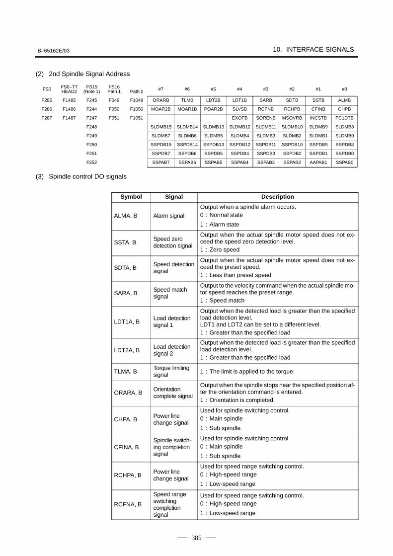
B–65162E/03 10. INTERFACE SIGNALS
385
(2) 2nd Spindle Signal Address
FS0 FS0–TTHEAD2
FS15(Note 1)
FS16Path 1 Path 2 #7 #6 #5 #4 #3 #2 #1 #0
F285 F1485 F245 F049 F1049 ORARB TLMB LDT2B LDT1B SARB SDTB SSTB ALMB
F286 F1486 F244 F050 F1050 MOAR2B MOAR1B POAR2B SLVSB RCFNB RCHPB CFINB CHPB
F287 F1487 F247 F051 F1051 EXOFB SORENB MSOVRB INCSTB PC1DTB
F248 SLDMB15 SLDMB14 SLDMB13 SLDMB12 SLDMB11 SLDMB10 SLDMB9 SLDMB8
F249 SLDMB7 SLDMB6 SLDMB5 SLDMB4 SLDMB3 SLDMB2 SLDMB1 SLDMB0
F250 SSPDB15 SSPDB14 SSPDB13 SSPDB12 SSPDB11 SSPDB10 SSPDB9 SSPDB8
F251 SSPDB7 SSPDB6 SSPDB5 SSPDB4 SSPDB3 SSPDB2 SSPDB1 SSPDB0
F252 SSPAB7 SSPAB6 SSPAB5 SSPAB4 SSPAB3 SSPAB2 AAPAB1 SSPAB0
(3) Spindle control DO signals
Symbol Signal Description
ALMA, B Alarm signal
Output when a spindle alarm occurs.0 : Normal state
1 : Alarm state
SSTA, BSpeed zerodetection signal
Output when the actual spindle motor speed does not ex-ceed the speed zero detection level.1 : Zero speed
SDTA, BSpeed detectionsignal
Output when the actual spindle motor speed does not ex-ceed the preset speed.1 : Less than preset speed
SARA, BSpeed matchsignal
Output to the velocity command when the actual spindle mo-tor speed reaches the preset range.1 : Speed match
LDT1A, BLoad detectionsignal 1
Output when the detected load is greater than the specifiedload detection level.LDT1 and LDT2 can be set to a different level.1 : Greater than the specified load
LDT2A, BLoad detectionsignal 2
Output when the detected load is greater than the specifiedload detection level.1 : Greater than the specified load
TLMA, BTorque limitingsignal 1 : The limit is applied to the torque.
ORARA, BOrientationcomplete signal
Output when the spindle stops near the specified position af-ter the orientation command is entered.1 : Orientation is completed.
CHPA, BPower linechange signal
Used for spindle switching control.0 : Main spindle
1 : Sub spindle
CFINA, BSpindle switch-ing completionsignal
Used for spindle switching control.0 : Main spindle
1 : Sub spindle
RCHPA, BPower linechange signal
Used for speed range switching control.0 : High-speed range
1 : Low-speed range
RCFNA, B
Speed rangeswitchingcompletionsignal
Used for speed range switching control.0 : High-speed range
1 : Low-speed range
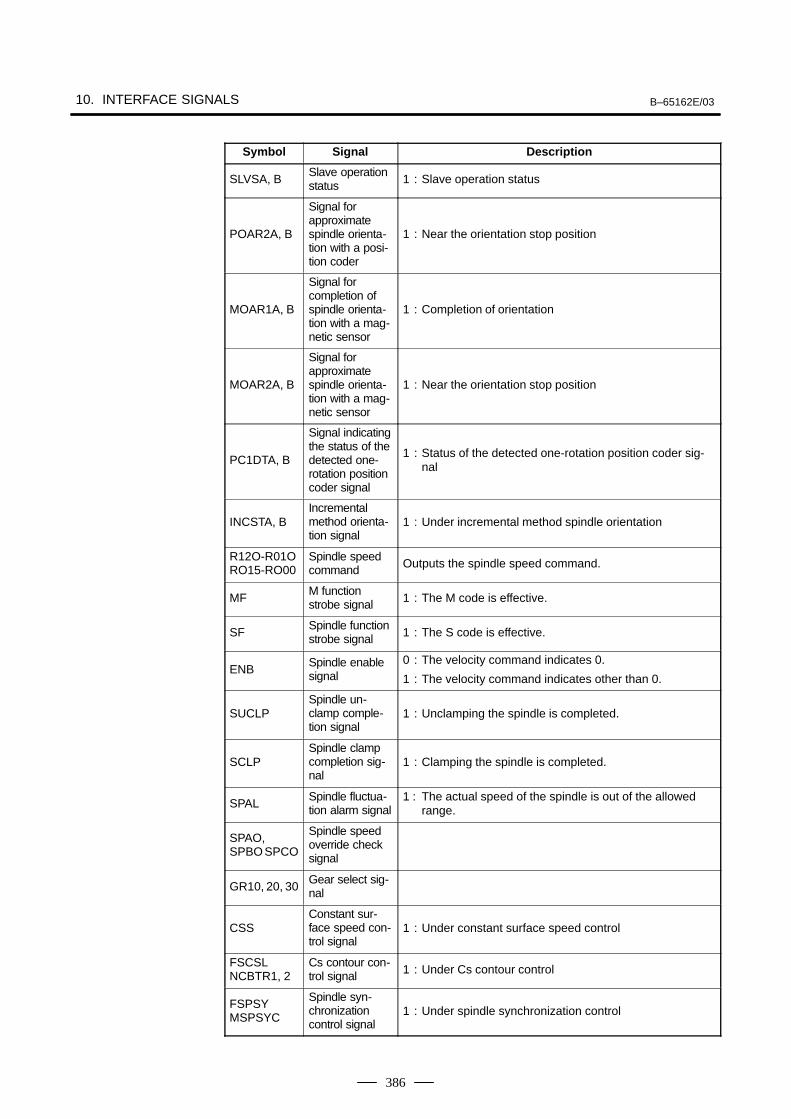
10. INTERFACE SIGNALS B–65162E/03
386
Symbol DescriptionSignal
SLVSA, BSlave operationstatus 1 : Slave operation status
POAR2A, B
Signal forapproximatespindle orienta-tion with a posi-tion coder
1 : Near the orientation stop position
MOAR1A, B
Signal forcompletion ofspindle orienta-tion with a mag-netic sensor
1 : Completion of orientation
MOAR2A, B
Signal forapproximatespindle orienta-tion with a mag-netic sensor
1 : Near the orientation stop position
PC1DTA, B
Signal indicatingthe status of thedetected one-rotation positioncoder signal
1 : Status of the detected one-rotation position coder sig-nal
INCSTA, BIncrementalmethod orienta-tion signal
1 : Under incremental method spindle orientation
R12O-R01ORO15-RO00
Spindle speedcommand Outputs the spindle speed command.
MFM functionstrobe signal 1 : The M code is effective.
SFSpindle functionstrobe signal 1 : The S code is effective.
ENBSpindle enablesignal
0 : The velocity command indicates 0.
1 : The velocity command indicates other than 0.
SUCLPSpindle un-clamp comple-tion signal
1 : Unclamping the spindle is completed.
SCLPSpindle clampcompletion sig-nal
1 : Clamping the spindle is completed.
SPALSpindle fluctua-tion alarm signal
1 : The actual speed of the spindle is out of the allowedrange.
SPAO,SPBO SPCO
Spindle speedoverride checksignal
GR10, 20, 30Gear select sig-nal
CSSConstant sur-face speed con-trol signal
1 : Under constant surface speed control
FSCSLNCBTR1, 2
Cs contour con-trol signal 1 : Under Cs contour control
FSPSYMSPSYC
Spindle syn-chronizationcontrol signal
1 : Under spindle synchronization control
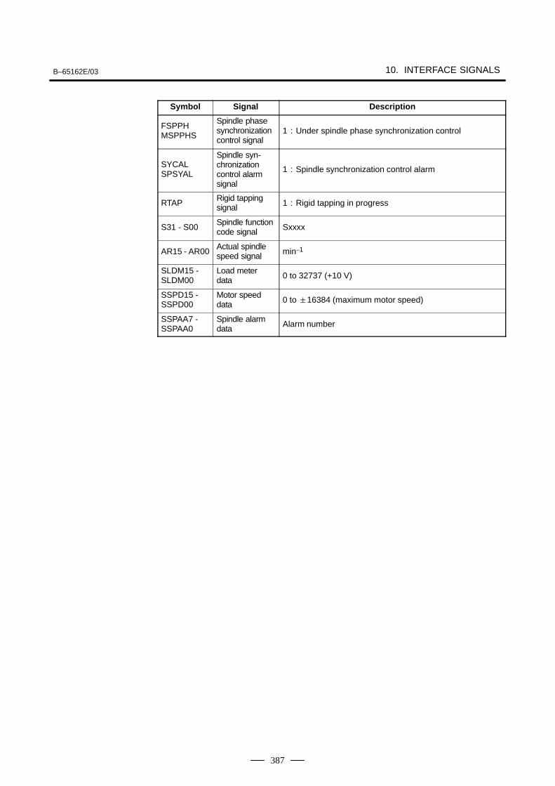
B–65162E/03 10. INTERFACE SIGNALS
387
Symbol DescriptionSignal
FSPPHMSPPHS
Spindle phasesynchronizationcontrol signal
1 : Under spindle phase synchronization control
SYCALSPSYAL
Spindle syn-chronizationcontrol alarmsignal
1 : Spindle synchronization control alarm
RTAPRigid tappingsignal 1 : Rigid tapping in progress
S31 - S00Spindle functioncode signal Sxxxx
AR15 - AR00Actual spindlespeed signal min–1
SLDM15 - SLDM00
Load meterdata 0 to 32737 (+10 V)
SSPD15 - SSPD00
Motor speeddata 0 to 16384 (maximum motor speed)
SSPAA7 - SSPAA0
Spindle alarmdata Alarm number
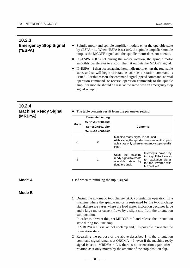
10. INTERFACE SIGNALS B–65162E/03
388
Spindle motor and spindle amplifier module enter the operable stateby *ESPA = 1. When *ESPA is set to 0, the spindle amplifier moduleoutputs the MCOFF signal and the spindle motor does not operate.
If *ESPA = 0 is set during the motor rotation, the spindle motorsmoothly decelerates to a stop. Then, it outputs the MCOFF signal.
If *ESPA = 1 then occurs again, the spindle motor enters the rotateablestate, and so will begin to rotate as soon as a rotation command isissued. For this reason, the command signal (speed command, normaloperation command, or reverse operation command) to the spindleamplifier module should be reset at the same time an emergency stopsignal is input.
The table contents result from the parameter setting.
Parameter setting
ModeSeries15:3001-bit0
Series0:6501-bit0
Series16:4001-bit0
Contents
A 0
Machine ready signal is not used.At this time, the spindle motor enters the oper-able state only when emergency stop signal isinput.
B 1
Uses the machineready signal to createoperable state bydouble signal.
Intercepts power byturning off the transis-tor excitation signalfor the inverter withMRDYA = 0.
Used when minimizing the input signal.
1 During the automatic tool change (ATC) orientation operation, in amachine where the spindle motor is restrained by the tool unclampsignal,there are cases where the load meter indication becomes largeand a large motor current flows by a slight slip from the orientationstop position.In order to prevent this, set MRDYA = 0 and release the orientationstate during tool unclamp.If MRDYA = 1 is set at tool unclamp end, it is possible to re-enter theorientation state.
2 Regarding the purpose of the above described 1, if the orientationcommand signal remains at ORCMA = 1, even if the machine readysignal is set to MRDYA = 0/1, there is no orientation again after 1rotation as it only moves by the amount of the stop position slip.
10.2.3Emergency Stop Signal(*ESPA)
10.2.4Machine Ready Signal(MRDYA)
Mode A
Mode B
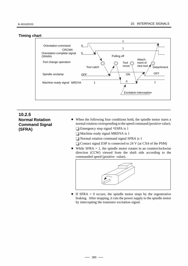
B–65162E/03 10. INTERFACE SIGNALS
389
Orientation commandCRCMA
1
1
1
0
0
Pulling off
Toolmove
10
OFF
Orientation complete signalORARA
Spindle unclamp
Tool change operation
Excitation interception
Tool catch Detachment
Attach-ment ofnew tool
MRDYAMachine ready signal
ON OFF
When the following four conditions hold, the spindle motor starts anormal rotation corresponding to the speed command (positive value).
Emergency stop signal *ESPA is 1
Machine ready signal MRDYA is 1
Normal rotation command signal SFRA is 1
Contact signal ESP is connected to 24 V (at CX4 of the PSM)
While SFRA = 1, the spindle motor rotates in an counterclockwisedirection (CCW) viewed from the shaft side according to thecommanded speed (positive value).
If SFRA = 0 occurs, the spindle motor stops by the regenerativebraking. After stopping, it cuts the power supply to the spindle motorby intercepting the transistor excitation signal.
Timing chart
10.2.5Normal RotationCommand Signal(SFRA)
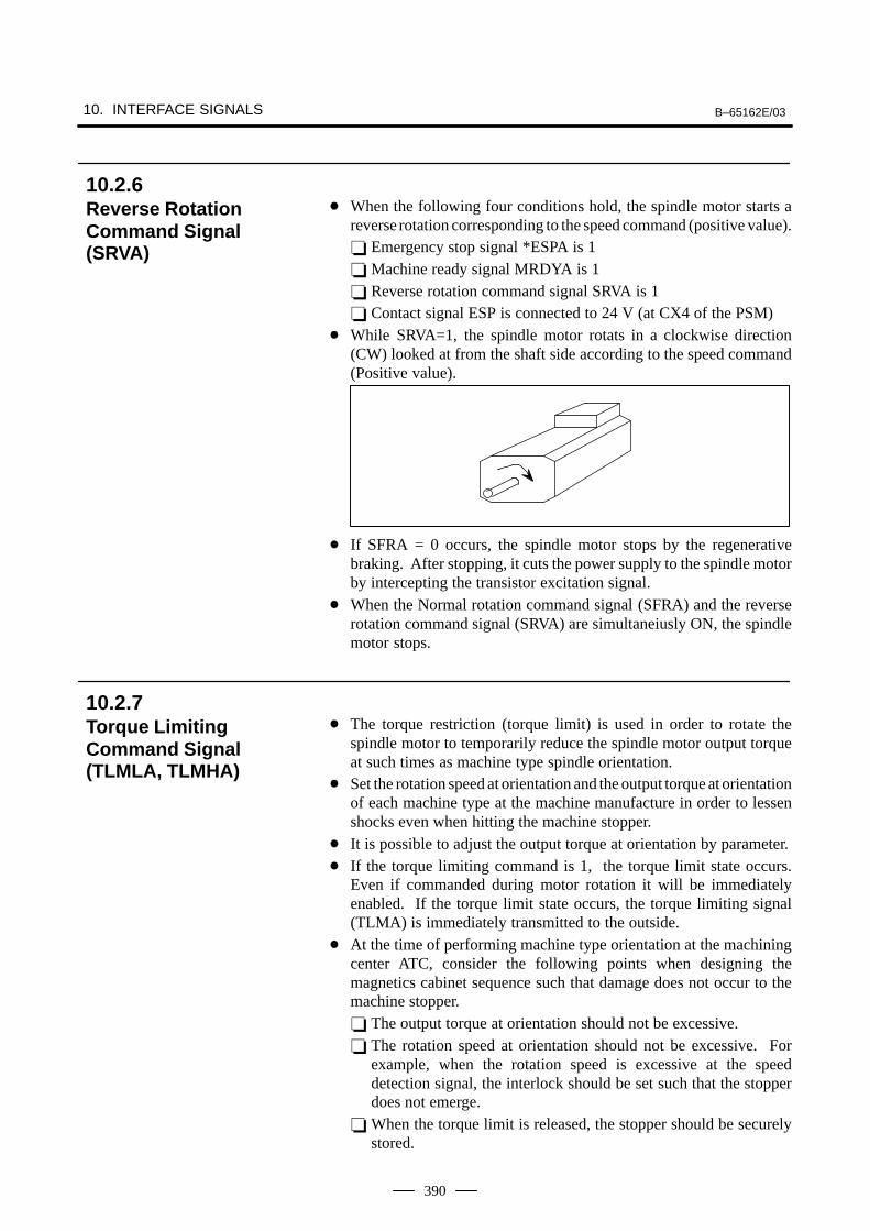
10. INTERFACE SIGNALS B–65162E/03
390
When the following four conditions hold, the spindle motor starts areverse rotation corresponding to the speed command (positive value). Emergency stop signal *ESPA is 1 Machine ready signal MRDYA is 1 Reverse rotation command signal SRVA is 1 Contact signal ESP is connected to 24 V (at CX4 of the PSM)
While SRVA=1, the spindle motor rotats in a clockwise direction(CW) looked at from the shaft side according to the speed command(Positive value).
If SFRA = 0 occurs, the spindle motor stops by the regenerativebraking. After stopping, it cuts the power supply to the spindle motorby intercepting the transistor excitation signal.
When the Normal rotation command signal (SFRA) and the reverserotation command signal (SRVA) are simultaneiusly ON, the spindlemotor stops.
The torque restriction (torque limit) is used in order to rotate thespindle motor to temporarily reduce the spindle motor output torqueat such times as machine type spindle orientation.
Set the rotation speed at orientation and the output torque at orientationof each machine type at the machine manufacture in order to lessenshocks even when hitting the machine stopper.
It is possible to adjust the output torque at orientation by parameter. If the torque limiting command is 1, the torque limit state occurs.
Even if commanded during motor rotation it will be immediatelyenabled. If the torque limit state occurs, the torque limiting signal(TLMA) is immediately transmitted to the outside.
At the time of performing machine type orientation at the machiningcenter ATC, consider the following points when designing themagnetics cabinet sequence such that damage does not occur to themachine stopper. The output torque at orientation should not be excessive. The rotation speed at orientation should not be excessive. For
example, when the rotation speed is excessive at the speeddetection signal, the interlock should be set such that the stopperdoes not emerge.
When the torque limit is released, the stopper should be securelystored.
10.2.6Reverse RotationCommand Signal(SRVA)
10.2.7Torque LimitingCommand Signal(TLMLA, TLMHA)
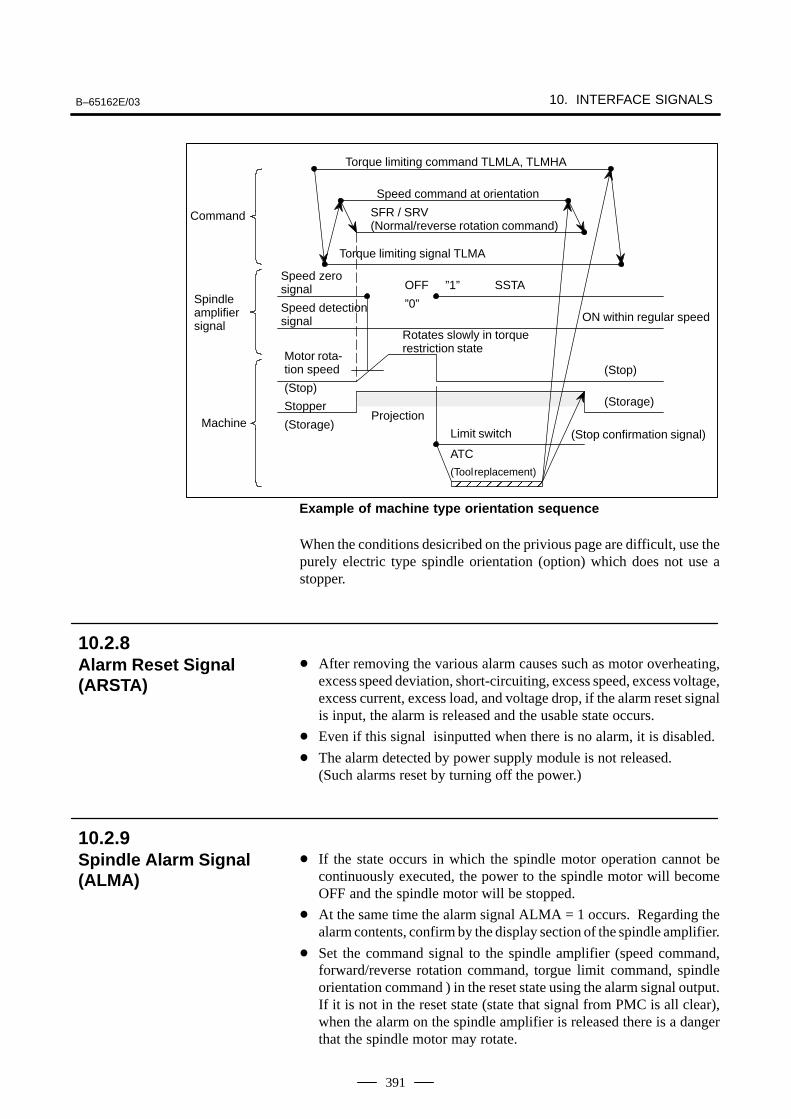
B–65162E/03 10. INTERFACE SIGNALS
391
”1” SSTA
ATC
(Tool replacement)
Speed zerosignal
SFR / SRV (Normal/reverse rotation command)
Command
Spindleamplifiersignal
Machine
Motor rota-tion speed
(Stop)
Stopper
(Storage)
Rotates slowly in torquerestriction state
Speed detectionsignal
Speed command at orientation
Torque limiting command TLMLA, TLMHA
Torque limiting signal TLMA
OFF
”0”ON within regular speed
(Stop)
(Storage)Projection
Limit switch
ÅÅÅÅÅÅ
(Stop confirmation signal)
Example of machine type orientation sequence
When the conditions desicribed on the privious page are difficult, use thepurely electric type spindle orientation (option) which does not use astopper.
After removing the various alarm causes such as motor overheating,excess speed deviation, short-circuiting, excess speed, excess voltage,excess current, excess load, and voltage drop, if the alarm reset signalis input, the alarm is released and the usable state occurs.
Even if this signal isinputted when there is no alarm, it is disabled.
The alarm detected by power supply module is not released.(Such alarms reset by turning off the power.)
If the state occurs in which the spindle motor operation cannot becontinuously executed, the power to the spindle motor will becomeOFF and the spindle motor will be stopped.
At the same time the alarm signal ALMA = 1 occurs. Regarding thealarm contents, confirm by the display section of the spindle amplifier.
Set the command signal to the spindle amplifier (speed command,forward/reverse rotation command, torgue limit command, spindleorientation command ) in the reset state using the alarm signal output.If it is not in the reset state (state that signal from PMC is all clear),when the alarm on the spindle amplifier is released there is a dangerthat the spindle motor may rotate.
10.2.8Alarm Reset Signal(ARSTA)
10.2.9Spindle Alarm Signal(ALMA)
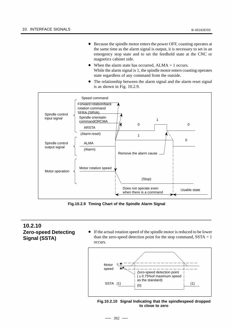
10. INTERFACE SIGNALS B–65162E/03
392
Because the spindle motor enters the power OFF, coasting operates atthe same time as the alarm signal is output, it is necessary to set in anemergency stop state and to set the feedhold state at the CNC ormagnetics cabinet side.
When the alarm state has occurred, ALMA = 1 occurs.While the alarm signal is 1, the spindle motor enters coasting operatesstate regardless of any command from the outside.
The relationship between the alarm signal and the alarm reset signalis as shown in Fig. 10.2.9.
Forward rotation/backrotation commandSFRA (SRVA)
1
10
(Stop)
Motor rotation speed
Does not operate evenwhen there is a command
Usable state
Motor operation
Spindle controloutput signal
Spindle control input signal
0
Remove the alarm cause
(Alarm reset)
Speed command
ARSTA
(Alarm)
ALMA
0
Spindle orientatincommandORCMA
Fig.10.2.9 Timing Chart of the Spindle Alarm Signal
If the actual rotation speed of the spindle motor is reduced to be lowerthan the zero-speed detection point for the stop command, SSTA = 1occurs.
Zero-speed detection point(0.75%of maximum speedas the standard)
(0)
0
SSTA (1) (1)
Motorspeed
Fig.10.2.10 Signal Indicating that the spindlespeed droppedto close to zero
10.2.10Zero-speed DetectingSignal (SSTA)
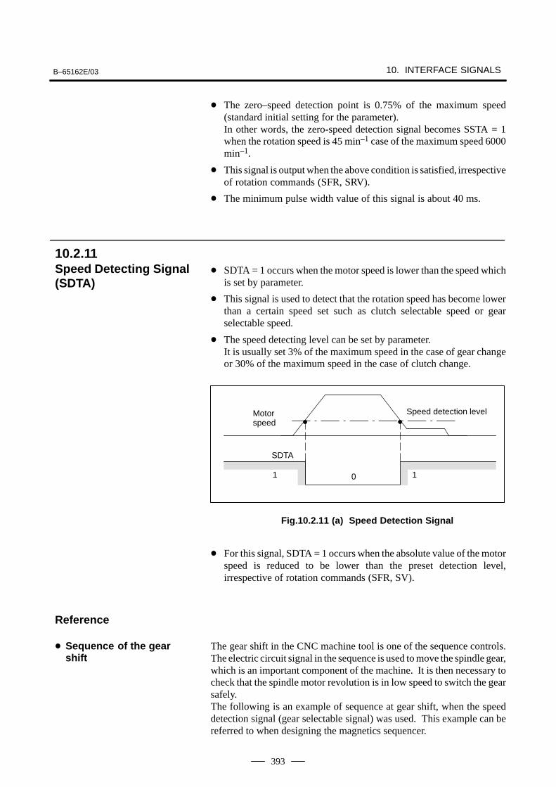
B–65162E/03 10. INTERFACE SIGNALS
393
The zero–speed detection point is 0.75% of the maximum speed(standard initial setting for the parameter).In other words, the zero-speed detection signal becomes SSTA = 1when the rotation speed is 45 min–1 case of the maximum speed 6000min–1.
This signal is output when the above condition is satisfied, irrespectiveof rotation commands (SFR, SRV).
The minimum pulse width value of this signal is about 40 ms.
SDTA = 1 occurs when the motor speed is lower than the speed whichis set by parameter.
This signal is used to detect that the rotation speed has become lowerthan a certain speed set such as clutch selectable speed or gearselectable speed.
The speed detecting level can be set by parameter.It is usually set 3% of the maximum speed in the case of gear changeor 30% of the maximum speed in the case of clutch change.
0
SDTA
1
Speed detection level
1
Motorspeed
Fig.10.2.11 (a) Speed Detection Signal
For this signal, SDTA = 1 occurs when the absolute value of the motorspeed is reduced to be lower than the preset detection level,irrespective of rotation commands (SFR, SV).
The gear shift in the CNC machine tool is one of the sequence controls.The electric circuit signal in the sequence is used to move the spindle gear,which is an important component of the machine. It is then necessary tocheck that the spindle motor revolution is in low speed to switch the gearsafely.The following is an example of sequence at gear shift, when the speeddetection signal (gear selectable signal) was used. This example can bereferred to when designing the magnetics sequencer.
10.2.11Speed Detecting Signal(SDTA)
Reference
Sequence of the gearshift
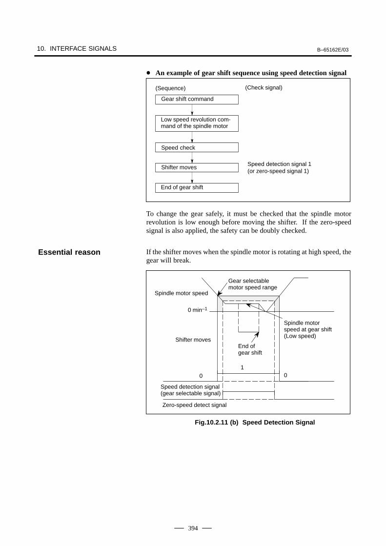
10. INTERFACE SIGNALS B–65162E/03
394
An example of gear shift sequence using speed detection signal
Speed detection signal 1(or zero-speed signal 1)
(Sequence) (Check signal)
Low speed revolution com-mand of the spindle motor
Speed check
Shifter moves
End of gear shift
Gear shift command
To change the gear safely, it must be checked that the spindle motorrevolution is low enough before moving the shifter. If the zero-speedsignal is also applied, the safety can be doubly checked.
If the shifter moves when the spindle motor is rotating at high speed, thegear will break.
1
Gear selectable motor speed range
Zero-speed detect signal
Speed detection signal(gear selectable signal)
Spindle motor speed
0
Spindle motorspeed at gear shift(Low speed)
0 min–1
Shifter moves
0
End ofgear shift
Fig.10.2.11 (b) Speed Detection Signal
Essential reason
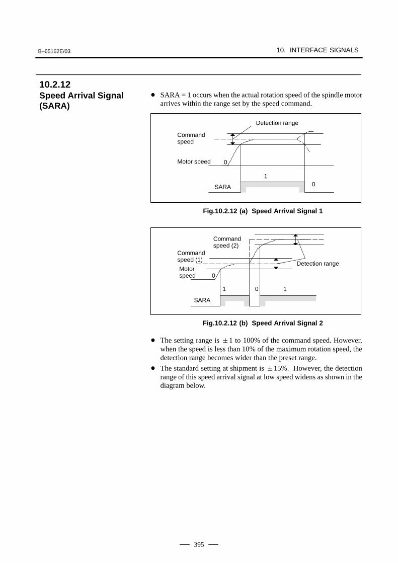
B–65162E/03 10. INTERFACE SIGNALS
395
SARA = 1 occurs when the actual rotation speed of the spindle motorarrives within the range set by the speed command.
1
Commandspeed
0
Detection range
SARA
Motor speed 0
Fig.10.2.12 (a) Speed Arrival Signal 1
0
Detection range
Commandspeed (2)
Motorspeed 0
SARA
1
Commandspeed (1)
1
Fig.10.2.12 (b) Speed Arrival Signal 2
The setting range is 1 to 100% of the command speed. However,when the speed is less than 10% of the maximum rotation speed, thedetection range becomes wider than the preset range.
The standard setting at shipment is 15%. However, the detectionrange of this speed arrival signal at low speed widens as shown in thediagram below.
10.2.12Speed Arrival Signal(SARA)
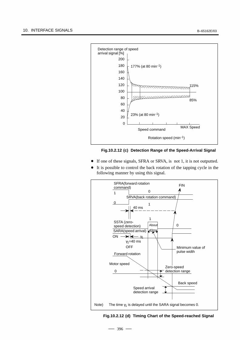
10. INTERFACE SIGNALS B–65162E/03
396
Speed command
0
20
40
60
80
100
120
140
160
180
200
MAX Speed
115%
85%
177% (at 80 min–1)
23% (at 80 min–1)
Rotation speed (min–1)
Detection range of speed arrival signal [%]
Fig.10.2.12 (c) Detection Range of the Speed-Arrival Signal
If one of these signals, SFRA or SRVA, is not 1, it is not outputted.
It is possible to control the back rotation of the tapping cycle in thefollowing manner by using this signal.
About
40ms
0
Minimum value ofpulse width
0
0
Forward rotation
Speed arrivaldetection range
SSTA (zero-speed detection)SARA(speed arrival)
ONγ1=40 ms
OFF
1
0
40 ms
1
SFRA(forward rotationcommand)
SRVA(back rotation command)
Zero-speeddetection range
Motor speed
FIN
Back speed
γ1
1
Note) The time γ1 is delayed until the SARA signal becomes 0.
Fig.10.2.12 (d) Timing Chart of the Speed-reached Signal
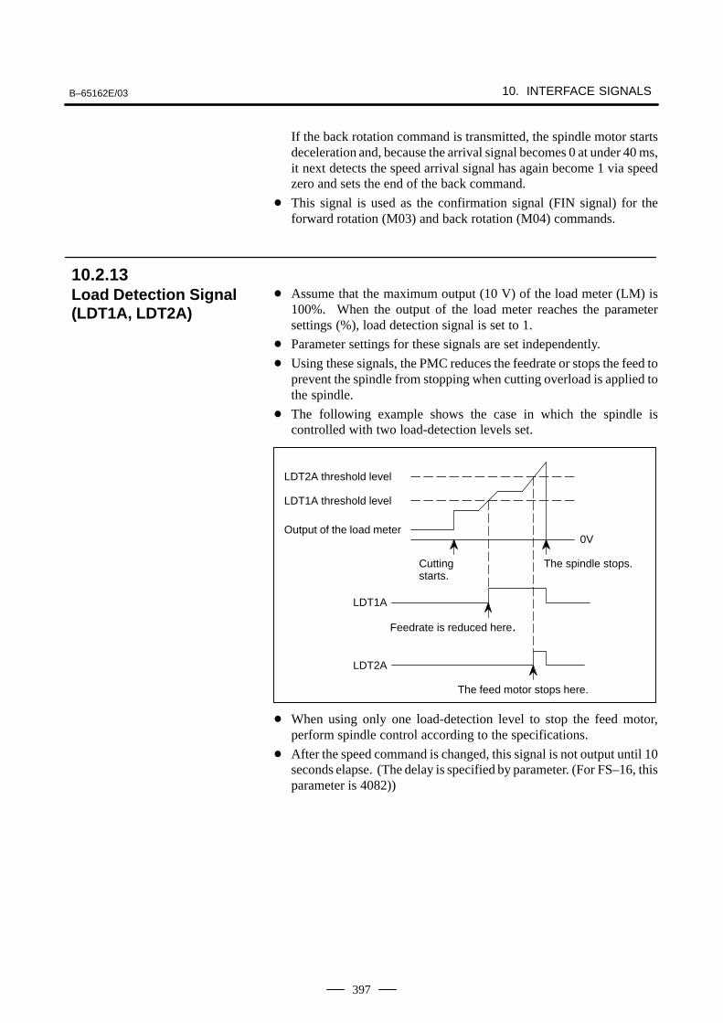
B–65162E/03 10. INTERFACE SIGNALS
397
If the back rotation command is transmitted, the spindle motor startsdeceleration and, because the arrival signal becomes 0 at under 40 ms,it next detects the speed arrival signal has again become 1 via speedzero and sets the end of the back command.
This signal is used as the confirmation signal (FIN signal) for theforward rotation (M03) and back rotation (M04) commands.
Assume that the maximum output (10 V) of the load meter (LM) is100%. When the output of the load meter reaches the parametersettings (%), load detection signal is set to 1.
Parameter settings for these signals are set independently.
Using these signals, the PMC reduces the feedrate or stops the feed toprevent the spindle from stopping when cutting overload is applied tothe spindle.
The following example shows the case in which the spindle iscontrolled with two load-detection levels set.
Feedrate is reduced here.
The spindle stops.Cuttingstarts.
LDT2A threshold level
LDT1A threshold level
Output of the load meter
The feed motor stops here.
LDT1A
LDT2A
0V
When using only one load-detection level to stop the feed motor,perform spindle control according to the specifications.
After the speed command is changed, this signal is not output until 10seconds elapse. (The delay is specified by parameter. (For FS–16, thisparameter is 4082))
10.2.13Load Detection Signal(LDT1A, LDT2A)
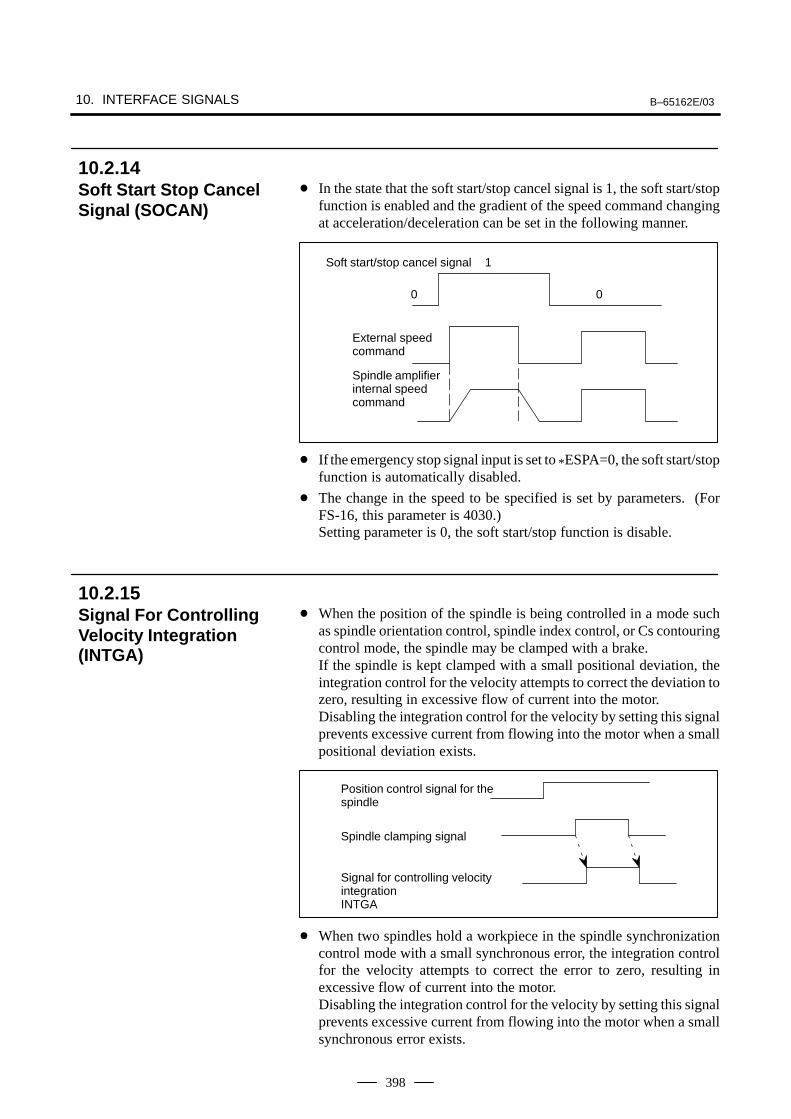
10. INTERFACE SIGNALS B–65162E/03
398
In the state that the soft start/stop cancel signal is 1, the soft start/stopfunction is enabled and the gradient of the speed command changingat acceleration/deceleration can be set in the following manner.
Soft start/stop cancel signal 1
0
External speedcommand
0
Spindle amplifierinternal speedcommand
If the emergency stop signal input is set to *ESPA=0, the soft start/stopfunction is automatically disabled.
The change in the speed to be specified is set by parameters. (ForFS-16, this parameter is 4030.)Setting parameter is 0, the soft start/stop function is disable.
When the position of the spindle is being controlled in a mode suchas spindle orientation control, spindle index control, or Cs contouringcontrol mode, the spindle may be clamped with a brake. If the spindle is kept clamped with a small positional deviation, theintegration control for the velocity attempts to correct the deviation tozero, resulting in excessive flow of current into the motor.Disabling the integration control for the velocity by setting this signalprevents excessive current from flowing into the motor when a smallpositional deviation exists.
Position control signal for thespindle
Spindle clamping signal
Signal for controlling velocity integrationINTGA
When two spindles hold a workpiece in the spindle synchronizationcontrol mode with a small synchronous error, the integration controlfor the velocity attempts to correct the error to zero, resulting inexcessive flow of current into the motor.Disabling the integration control for the velocity by setting this signalprevents excessive current from flowing into the motor when a smallsynchronous error exists.
10.2.14Soft Start Stop CancelSignal (SOCAN)
10.2.15Signal For ControllingVelocity Integration(INTGA)
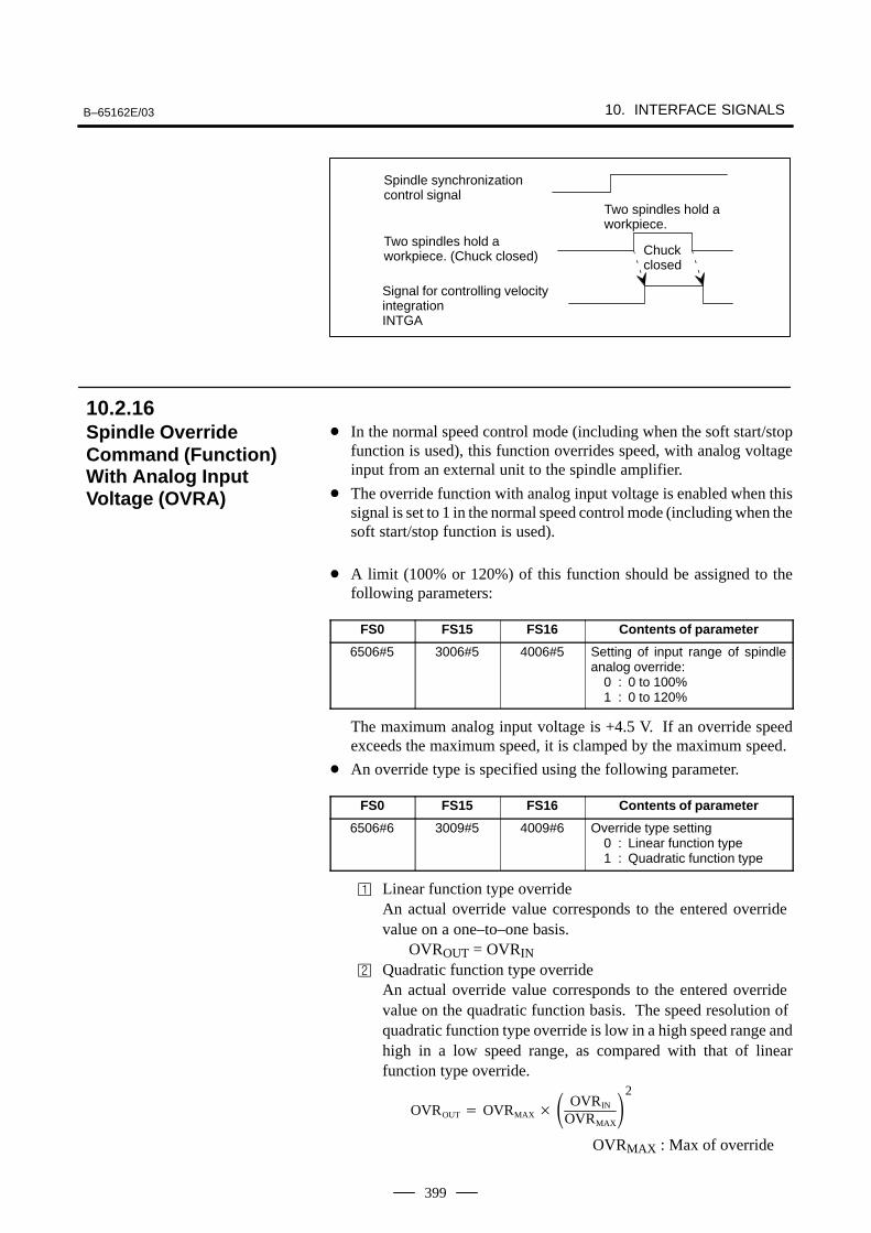
B–65162E/03 10. INTERFACE SIGNALS
399
Two spindles hold a workpiece. (Chuck closed)
Signal for controlling velocityintegrationINTGA
Chuckclosed
Two spindles hold aworkpiece.
Spindle synchronization control signal
In the normal speed control mode (including when the soft start/stopfunction is used), this function overrides speed, with analog voltageinput from an external unit to the spindle amplifier.
The override function with analog input voltage is enabled when thissignal is set to 1 in the normal speed control mode (including when thesoft start/stop function is used).
A limit (100% or 120%) of this function should be assigned to thefollowing parameters:
FS0 FS15 FS16 Contents of parameter
6506#5 3006#5 4006#5 Setting of input range of spindleanalog override:
0 : 0 to 100%1 : 0 to 120%
The maximum analog input voltage is +4.5 V. If an override speedexceeds the maximum speed, it is clamped by the maximum speed.
An override type is specified using the following parameter.
FS0 FS15 FS16 Contents of parameter
6506#6 3009#5 4009#6 Override type setting0 : Linear function type1 : Quadratic function type
Linear function type overrideAn actual override value corresponds to the entered override value on a one–to–one basis.
OVROUT = OVRIN Quadratic function type override
An actual override value corresponds to the entered override value on the quadratic function basis. The speed resolution of quadratic function type override is low in a high speed range andhigh in a low speed range, as compared with that of linearfunction type override.
OVROUT OVRMAX OVRIN
OVRMAX
2
OVRMAX : Max of override
10.2.16Spindle OverrideCommand (Function)With Analog InputVoltage (OVRA)
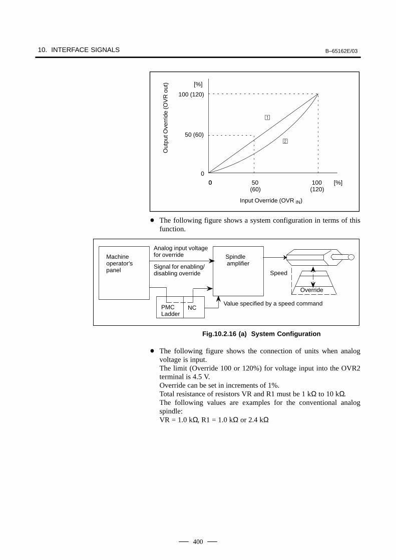
10. INTERFACE SIGNALS B–65162E/03
400
[%]
100 (120)
50 (60)
0
00 50(60)
100(120)
[%]
Out
put O
verr
ide
(OV
R o
ut)
Input Override (OVR IN)
The following figure shows a system configuration in terms of thisfunction.
Override
Value specified by a speed commandPMCLadder
NC
Machine operator’spanel
Spindle amplifier
Analog input voltagefor override
Signal for enabling/disabling override Speed
Fig.10.2.16 (a) System Configuration
The following figure shows the connection of units when analogvoltage is input.The limit (Override 100 or 120%) for voltage input into the OVR2terminal is 4.5 V.Override can be set in increments of 1%.Total resistance of resistors VR and R1 must be 1 kΩ to 10 kΩ. The following values are examples for the conventional analogspindle:VR = 1.0 kΩ, R1 = 1.0 kΩ or 2.4 kΩ
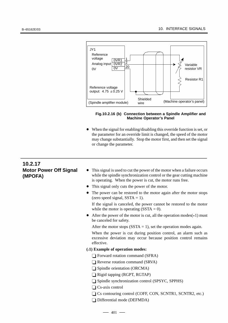
B–65162E/03 10. INTERFACE SIGNALS
401
0VR10VR20V
JY1
Referencevoltage
Analog input
0V
Reference voltageoutput: 4.75 0.25 V
Variableresistor VR
Resistor R1
Shieldedwire (Machine operator’s panel)(Spindle amplifier module)
1220
Fig.10.2.16 (b) Connection between a Spindle Amplifier andMachine Operator’s Panel
When the signal for enabling/disabling this override function is set, orthe parameter for an override limit is changed, the speed of the motormay change substantially. Stop the motor first, and then set the signalor change the parameter.
This signal is used to cut the power of the motor when a failure occurswhile the spindle synchronization control or the gear cutting machineis operating. When the power is cut, the motor runs free.
This signal only cuts the power of the motor.
The power can be restored to the motor again after the motor stops(zero speed signal, SSTA = 1).
If the signal is canceled, the power cannot be restored to the motorwhile the motor is operating (SSTA = 0).
After the power of the motor is cut, all the operation modes(*1) mustbe canceled for safety.
After the motor stops (SSTA = 1), set the operation modes again.
When the power is cut during position control, an alarm such asexcessive deviation may occur because position control remainseffective.
(*1) Example of operation modes:
Forward rotation command (SFRA)
Reverse rotation command (SRVA)
Spindle orientation (ORCMA)
Rigid tapping (RGPT, RGTAP)
Spindle synchronization control (SPSYC, SPPHS)
Cs-axis control
Cs contouring control (COFF, CON, SCNTR1, SCNTR2, etc.)
Differential mode (DEFMDA)
10.2.17Motor Power Off Signal(MPOFA)
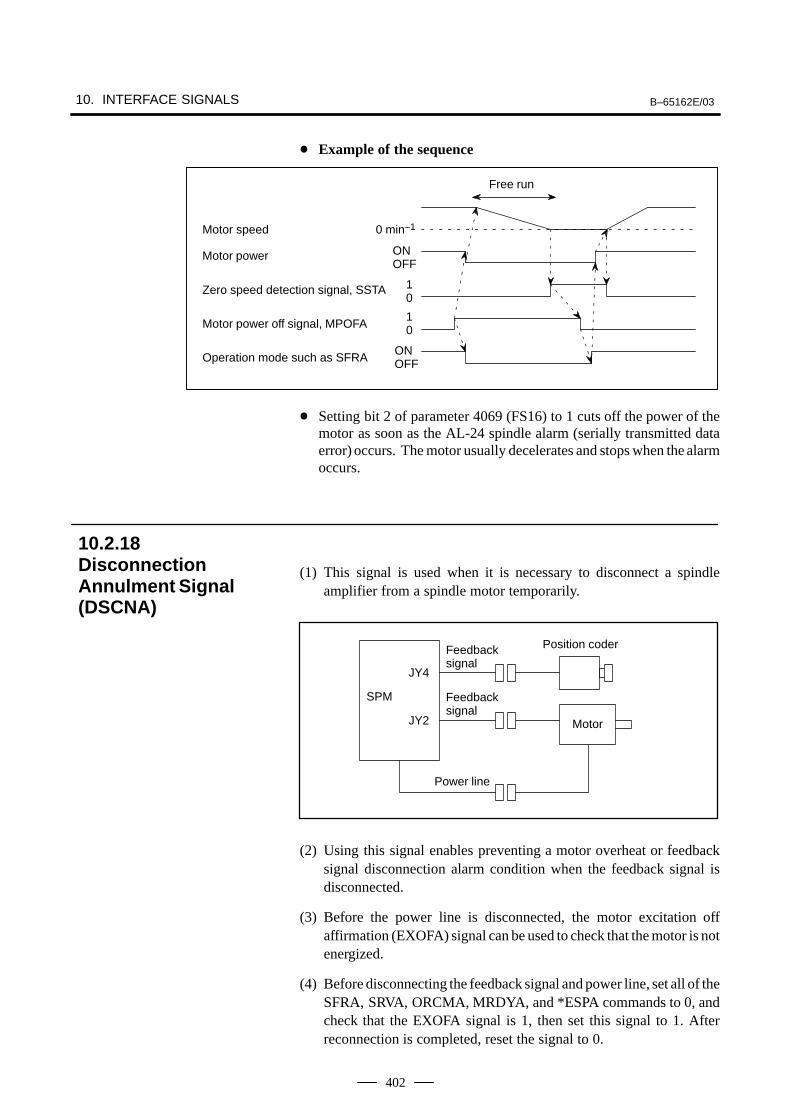
10. INTERFACE SIGNALS B–65162E/03
402
Example of the sequence
Motor speed
Motor power
Zero speed detection signal, SSTA
Motor power off signal, MPOFA
Operation mode such as SFRA
0 min–1
Free run
ONOFF
10
10
ONOFF
Setting bit 2 of parameter 4069 (FS16) to 1 cuts off the power of themotor as soon as the AL-24 spindle alarm (serially transmitted dataerror) occurs. The motor usually decelerates and stops when the alarmoccurs.
(1) This signal is used when it is necessary to disconnect a spindleamplifier from a spindle motor temporarily.
SPM
JY4
JY2
Feedbacksignal
Power line
Motor
Position coder
Feedbacksignal
(2) Using this signal enables preventing a motor overheat or feedbacksignal disconnection alarm condition when the feedback signal isdisconnected.
(3) Before the power line is disconnected, the motor excitation offaffirmation (EXOFA) signal can be used to check that the motor is notenergized.
(4) Before disconnecting the feedback signal and power line, set all of theSFRA, SRVA, ORCMA, MRDYA, and *ESPA commands to 0, andcheck that the EXOFA signal is 1, then set this signal to 1. Afterreconnection is completed, reset the signal to 0.
10.2.18DisconnectionAnnulment Signal(DSCNA)
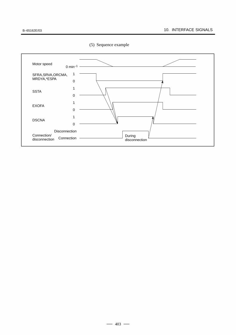
B–65162E/03 10. INTERFACE SIGNALS
403
(5) Sequence example
Motor speed0 min–1
0
1SFRA,SRVA,ORCMA,MRDYA,*ESPA
SSTA0
1
0
1EXOFA
0
1DSCNA
Connection/disconnection Connection
DisconnectionDuring disconnection
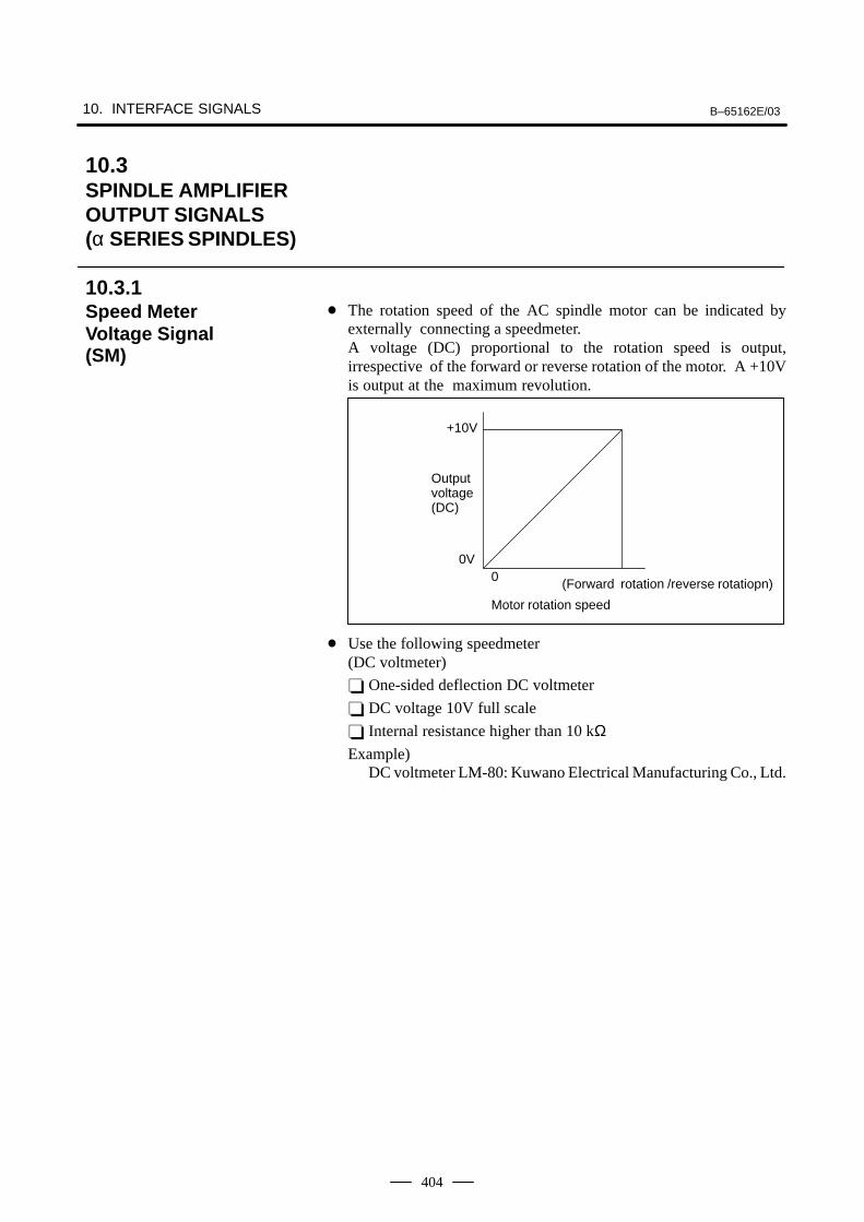
10. INTERFACE SIGNALS B–65162E/03
404
The rotation speed of the AC spindle motor can be indicated byexternally connecting a speedmeter.A voltage (DC) proportional to the rotation speed is output,irrespective of the forward or reverse rotation of the motor. A +10Vis output at the maximum revolution.
+10V
0V0
Outputvoltage(DC)
Motor rotation speed
(Forward rotation /reverse rotatiopn)
Use the following speedmeter(DC voltmeter)
One-sided deflection DC voltmeter
DC voltage 10V full scale
Internal resistance higher than 10 kΩExample)
DC voltmeter LM-80: Kuwano Electrical Manufacturing Co., Ltd.
10.3SPINDLE AMPLIFIER OUTPUT SIGNALS (α SERIES SPINDLES)
10.3.1Speed Meter Voltage Signal (SM)
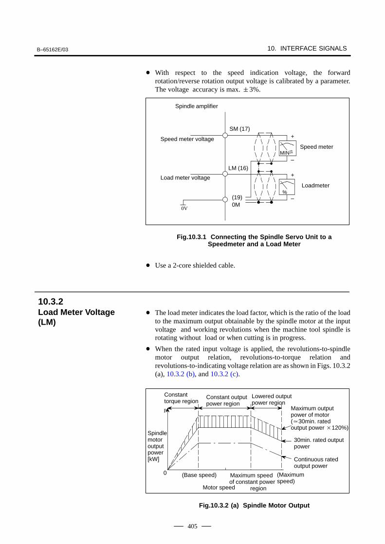
B–65162E/03 10. INTERFACE SIGNALS
405
With respect to the speed indication voltage, the forwardrotation/reverse rotation output voltage is calibrated by a parameter.The voltage accuracy is max. 3%.
MIN]1
%
+
+
–
–
Speed meter
Loadmeter
SM (17)
LM (16)
0M0V
Spindle amplifier
Speed meter voltage
Load meter voltage
(19)
Fig.10.3.1 Connecting the Spindle Servo Unit to aSpeedmeter and a Load Meter
Use a 2-core shielded cable.
The load meter indicates the load factor, which is the ratio of the loadto the maximum output obtainable by the spindle motor at the inputvoltage and working revolutions when the machine tool spindle isrotating without load or when cutting is in progress.
When the rated input voltage is applied, the revolutions-to-spindlemotor output relation, revolutions-to-torque relation andrevolutions-to-indicating voltage relation are as shown in Figs. 10.3.2(a), 10.3.2 (b), and 10.3.2 (c).
Lowered outputpower region
Constanttorque region
Constant outputpower region
30min. rated outputpower
Continuous ratedoutput power
(Base speed)
Motor speed
(Maximumspeed)
P
0
Maximum output power of motor(30min. rated output power 120%)
Spindlemotoroutputpower[kW]
Maximum speedof constant power region
Fig.10.3.2 (a) Spindle Motor Output
10.3.2Load Meter Voltage(LM)
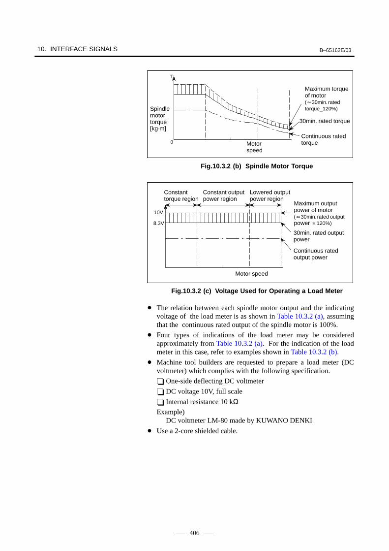
10. INTERFACE SIGNALS B–65162E/03
406
Maximum torqueof motor(30min. ratedtorque_120%)
30min. rated torque
Continuous ratedtorque
T
0
Spindlemotortorque[kg·m]
Motor speed
Fig.10.3.2 (b) Spindle Motor Torque
10V
Maximum outputpower of motor(30min. rated outputpower 120%)
30min. rated outputpower
Continuous ratedoutput power
8.3V
Motor speed
Lowered outputpower region
Constanttorque region
Constant outputpower region
Fig.10.3.2 (c) Voltage Used for Operating a Load Meter
The relation between each spindle motor output and the indicatingvoltage of the load meter is as shown in Table 10.3.2 (a), assumingthat the continuous rated output of the spindle motor is 100%.
Four types of indications of the load meter may be consideredapproximately from Table 10.3.2 (a). For the indication of the loadmeter in this case, refer to examples shown in Table 10.3.2 (b).
Machine tool builders are requested to prepare a load meter (DCvoltmeter) which complies with the following specification.
One-side deflecting DC voltmeter
DC voltage 10V, full scale
Internal resistance 10 kΩExample)
DC voltmeter LM-80 made by KUWANO DENKI
Use a 2-core shielded cable.
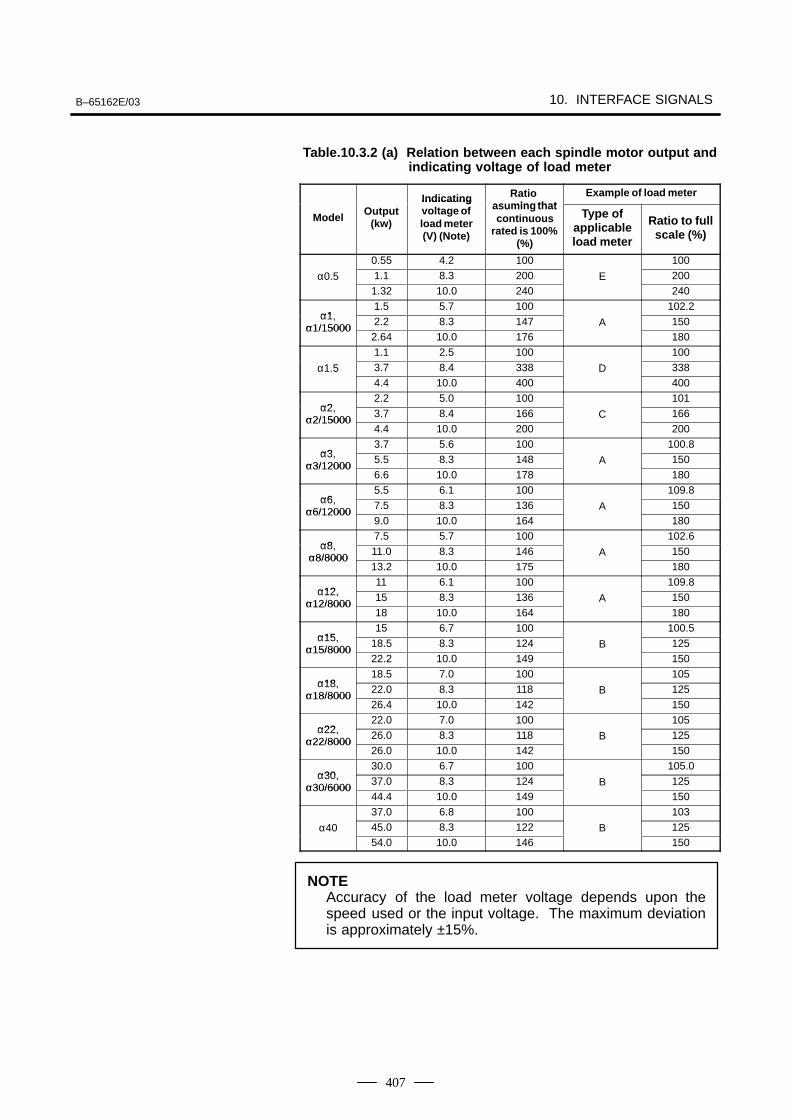
B–65162E/03 10. INTERFACE SIGNALS
407
Table.10.3.2 (a) Relation between each spindle motor output andindicating voltage of load meter
Indicating Ratio as ming that
Example of load meter
ModelOutput
(kw)
Indicatingvoltage ofload meter(V) (Note)
asuming thatcontinuous
rated is 100%(%)
Type ofapplicableload meter
Ratio to fullscale (%)
0.55 4.2 100 100
α0.5 1.1 8.3 200 E 2001.32 10.0 240 240
α11.5 5.7 100 102.2
α1,α1/15000
2.2 8.3 147 A 150α1/150002.64 10.0 176 1801.1 2.5 100 100
α1.5 3.7 8.4 338 D 3384.4 10.0 400 400
α22.2 5.0 100 101
α2,α2/15000
3.7 8.4 166 C 166α2/150004.4 10.0 200 200
α33.7 5.6 100 100.8
α3,α3/12000
5.5 8.3 148 A 150α3/120006.6 10.0 178 180
α65.5 6.1 100 109.8
α6,α6/12000
7.5 8.3 136 A 150α6/120009.0 10.0 164 180
α87.5 5.7 100 102.6
α8,α8/8000
11.0 8.3 146 A 150α8/800013.2 10.0 175 180
α1211 6.1 100 109.8
α12,α12/8000
15 8.3 136 A 150α12/800018 10.0 164 180
α1515 6.7 100 100.5
α15,α15/8000
18.5 8.3 124 B 125α15/800022.2 10.0 149 150
α1818.5 7.0 100 105
α18,α18/8000
22.0 8.3 118 B 125α18/800026.4 10.0 142 150
α2222.0 7.0 100 105
α22,α22/8000
26.0 8.3 118 B 125α22/800026.0 10.0 142 150
α3030.0 6.7 100 105.0
α30,α30/6000
37.0 8.3 124 B 125α30/600044.4 10.0 149 15037.0 6.8 100 103
α40 45.0 8.3 122 B 12554.0 10.0 146 150
NOTEAccuracy of the load meter voltage depends upon thespeed used or the input voltage. The maximum deviationis approximately ±15%.
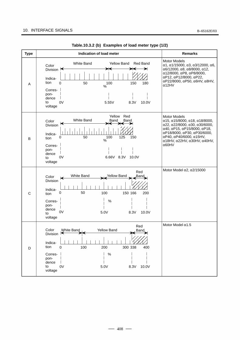
10. INTERFACE SIGNALS B–65162E/03
408
ÅÅÅÅÅÅÅÅÅ
ÅÅÅÅÅÅ
ÅÅÅÅÅÅ
ÅÅÅÅÅÅÅÅÅ
125
White Band Yellow Band Red Band
Type Indication of load meter Remarks
Motor Modelsα1, α1/15000, α3, α3/12000, α6,α6/12000, α8, α8/8000, α12,α12/8000, αP8, αP8/8000,αP12, αP12/8000, αP22,αP22/8000, αP50, α6HV, α8HV,α12HVA
B
Motor Modelsα15, α15/8000, α18, α18/8000,α22, α22/8000, α30, α30/6000,α40, αP15, αP15/8000, αP18,αP18/8000, αP30, αP30/6000,αP40, αP40/6000, α15HV,α18HV, α22HV, α30HV, α40HV,α60HV
0 50 100 150 180
0V 5.55V 8.3V 10.0V
%
0V 6.66V 10.0V8.3V
Table.10.3.2 (b) Examples of load meter type (1/2)
Motor Model α2, α2/15000
C
D
Motor Model α1.5
0 50 100 200
0V 5.0V 8.3V
%
166
0 100 200 300 400
0V 5.0V 8.3V 10.0V
338
150
10.0V
Corres-pon-denceto voltage
ColorDivision
Indica-tion
Corres-pon-denceto voltage
ColorDivision
Indica-tion
White BandYellowBand
RedBand
0 50 100 150%
White Band Yellow BandRedBand
Corres-pon-denceto voltage
ColorDivision
Indica-tion
Corres-pon-denceto voltage
ColorDivision
Indica-tion
White Band Yellow BandRedBand
%
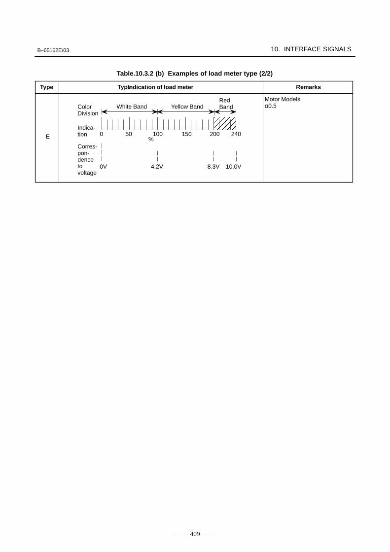
B–65162E/03 10. INTERFACE SIGNALS
409
Type
Motor Modelsα0.5
E
0V 4.2V 8.3V 10.0V
Table.10.3.2 (b) Examples of load meter type (2/2)
Corres-pon-denceto voltage
ColorDivision
Indica-tion
ÅÅÅÅÅÅÅÅ
200
White Band Yellow Band
0 50 100%
RedBand
240150
Type Indication of load meter Remarks

10. INTERFACE SIGNALS B–65162E/03
410
The abbreviations used in this manual stand for the following:
FS0 : Series 0-MC or 0-TCFS0–TT Head 2 : Head 2 of Series 0-TTCFS15 : Series 15FS16 : Series 16, Series 18, Series 20, Series 21
10.4SPINDLE CONTROL SIGNALS (αC SERIESSPINDLE)
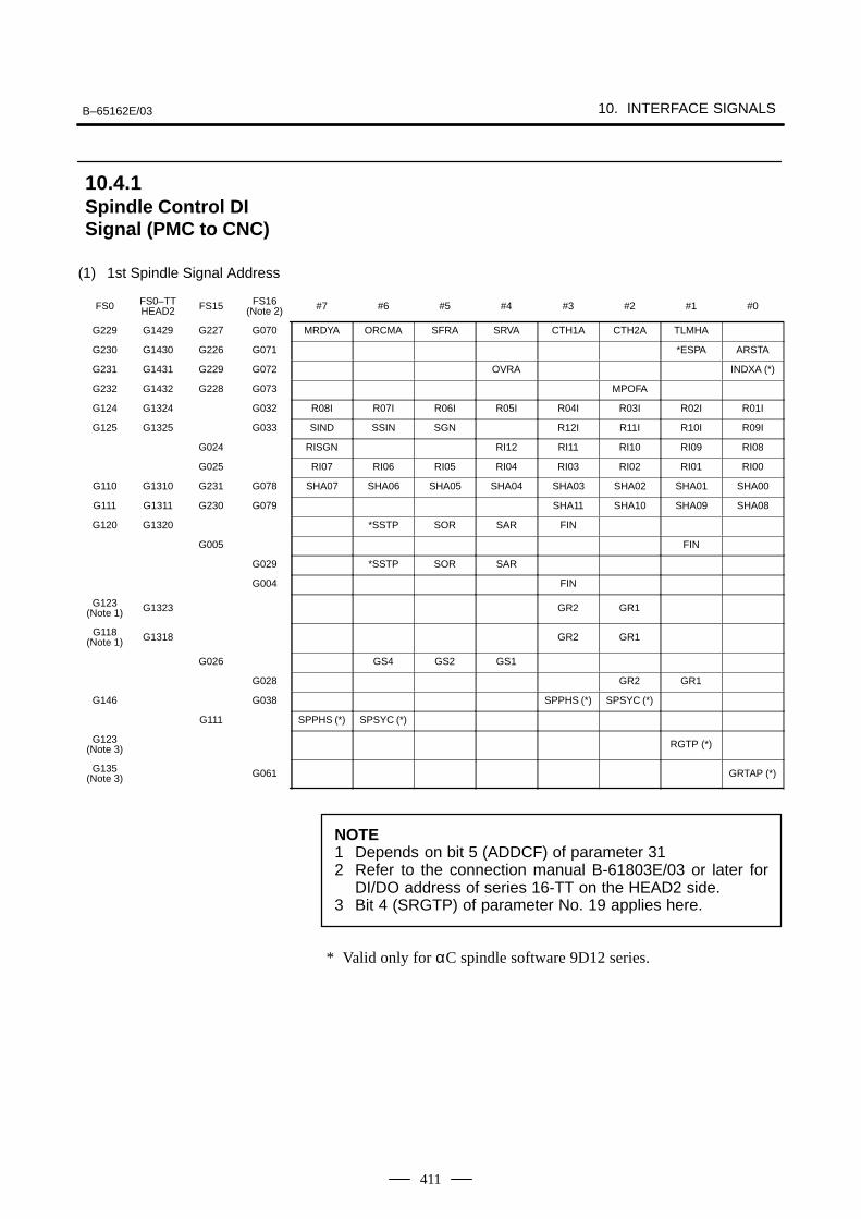
B–65162E/03 10. INTERFACE SIGNALS
411
(1) 1st Spindle Signal Address
FS0 FS0–TTHEAD2 FS15 FS16
(Note 2) #7 #6 #5 #4 #3 #2 #1 #0
G229 G1429 G227 G070 MRDYA ORCMA SFRA SRVA CTH1A CTH2A TLMHA
G230 G1430 G226 G071 *ESPA ARSTA
G231 G1431 G229 G072 OVRA INDXA (*)
G232 G1432 G228 G073 MPOFA
G124 G1324 G032 R08I R07I R06I R05I R04I R03I R02I R01I
G125 G1325 G033 SIND SSIN SGN R12I R11I R10I R09I
G024 RISGN RI12 RI11 RI10 RI09 RI08
G025 RI07 RI06 RI05 RI04 RI03 RI02 RI01 RI00
G110 G1310 G231 G078 SHA07 SHA06 SHA05 SHA04 SHA03 SHA02 SHA01 SHA00
G111 G1311 G230 G079 SHA11 SHA10 SHA09 SHA08
G120 G1320 *SSTP SOR SAR FIN
G005 FIN
G029 *SSTP SOR SAR
G004 FIN
G123(Note 1) G1323 GR2 GR1
G118(Note 1) G1318 GR2 GR1
G026 GS4 GS2 GS1
G028 GR2 GR1
G146 G038 SPPHS (*) SPSYC (*)
G111 SPPHS (*) SPSYC (*)
G123(Note 3) RGTP (*)
G135(Note 3) G061 GRTAP (*)
NOTE1 Depends on bit 5 (ADDCF) of parameter 312 Refer to the connection manual B-61803E/03 or later for
DI/DO address of series 16-TT on the HEAD2 side.3 Bit 4 (SRGTP) of parameter No. 19 applies here.
* Valid only for αC spindle software 9D12 series.
10.4.1Spindle Control DISignal (PMC to CNC)
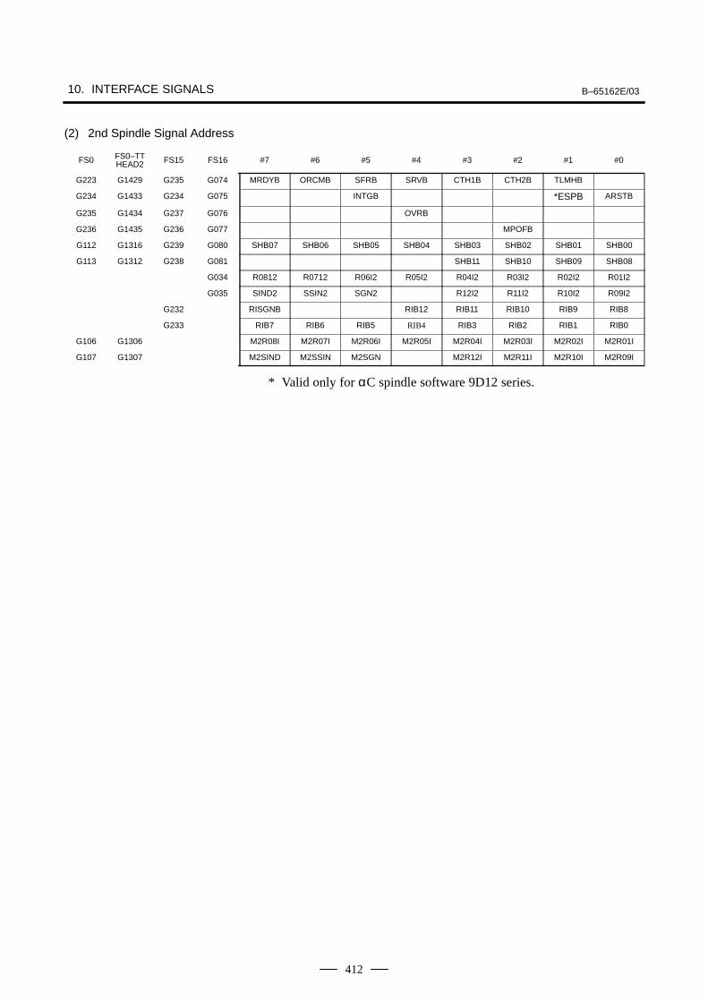
10. INTERFACE SIGNALS B–65162E/03
412
(2) 2nd Spindle Signal Address
FS0 FS0–TTHEAD2 FS15 FS16 #7 #6 #5 #4 #3 #2 #1 #0
G223 G1429 G235 G074 MRDYB ORCMB SFRB SRVB CTH1B CTH2B TLMHB
G234 G1433 G234 G075 INTGB *ESPB ARSTB
G235 G1434 G237 G076 OVRB
G236 G1435 G236 G077 MPOFB
G112 G1316 G239 G080 SHB07 SHB06 SHB05 SHB04 SHB03 SHB02 SHB01 SHB00
G113 G1312 G238 G081 SHB11 SHB10 SHB09 SHB08
G034 R0812 R0712 R06I2 R05I2 R04I2 R03I2 R02I2 R01I2
G035 SIND2 SSIN2 SGN2 R12I2 R11I2 R10I2 R09I2
G232 RISGNB RIB12 RIB11 RIB10 RIB9 RIB8
G233 RIB7 RIB6 RIB5 RIB4 RIB3 RIB2 RIB1 RIB0
G106 G1306 M2R08I M2R07I M2R06I M2R05I M2R04I M2R03I M2R02I M2R01I
G107 G1307 M2SIND M2SSIN M2SGN M2R12I M2R11I M2R10I M2R09I
* Valid only for αC spindle software 9D12 series.
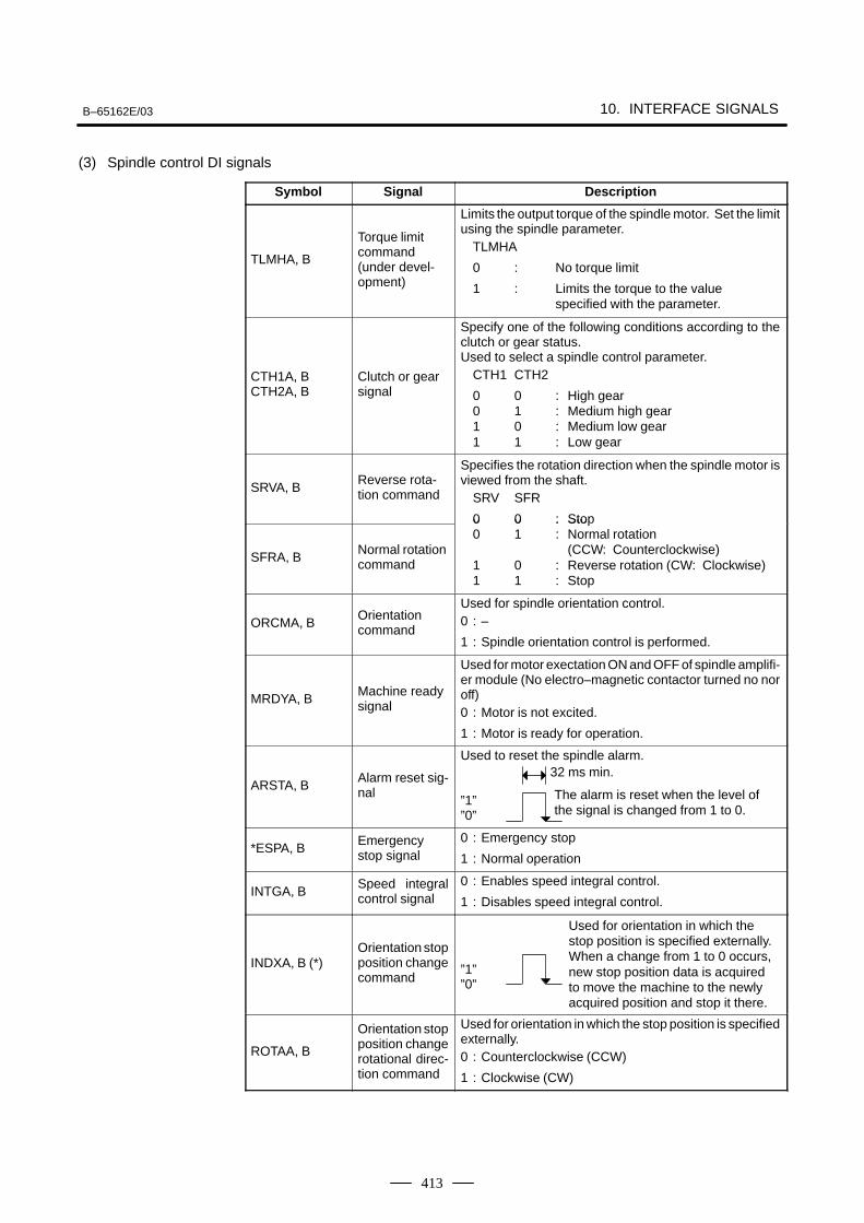
B–65162E/03 10. INTERFACE SIGNALS
413
(3) Spindle control DI signals
Symbol Signal Description
TLMHA, B
Torque limitcommand (under devel-opment)
Limits the output torque of the spindle motor. Set the limitusing the spindle parameter.
TLMHA
0 : No torque limit
1 : Limits the torque to the value specified with the parameter.
CTH1A, BCTH2A, B
Clutch or gearsignal
Specify one of the following conditions according to theclutch or gear status.Used to select a spindle control parameter.
CTH1 CTH2
0 0 : High gear0 1 : Medium high gear1 0 : Medium low gear1 1 : Low gear
SRVA, BReverse rota-tion command
Specifies the rotation direction when the spindle motor isviewed from the shaft.
SRV SFR
0 0 : Stop
SFRA, BNormal rotationcommand
0 0 : Sto0 1 : Normal rotation
(CCW: Counterclockwise)1 0 : Reverse rotation (CW: Clockwise)1 1 : Stop
ORCMA, BOrientationcommand
Used for spindle orientation control.0 : –
1 : Spindle orientation control is performed.
MRDYA, BMachine readysignal
Used for motor exectation ON and OFF of spindle amplifi-er module (No electro–magnetic contactor turned no noroff)0 : Motor is not excited.
1 : Motor is ready for operation.
ARSTA, BAlarm reset sig-nal
Used to reset the spindle alarm.
”1””0”
*ESPA, BEmergencystop signal
0 : Emergency stop
1 : Normal operation
INTGA, BSpeed integralcontrol signal
0 : Enables speed integral control.
1 : Disables speed integral control.
INDXA, B (*)Orientation stopposition changecommand
”1””0”
ROTAA, B
Orientation stopposition changerotational direc-tion command
Used for orientation in which the stop position is specifiedexternally.0 : Counterclockwise (CCW)
1 : Clockwise (CW)
The alarm is reset when the level ofthe signal is changed from 1 to 0.
32 ms min.
Used for orientation in which thestop position is specified externally.When a change from 1 to 0 occurs,new stop position data is acquiredto move the machine to the newlyacquired position and stop it there.
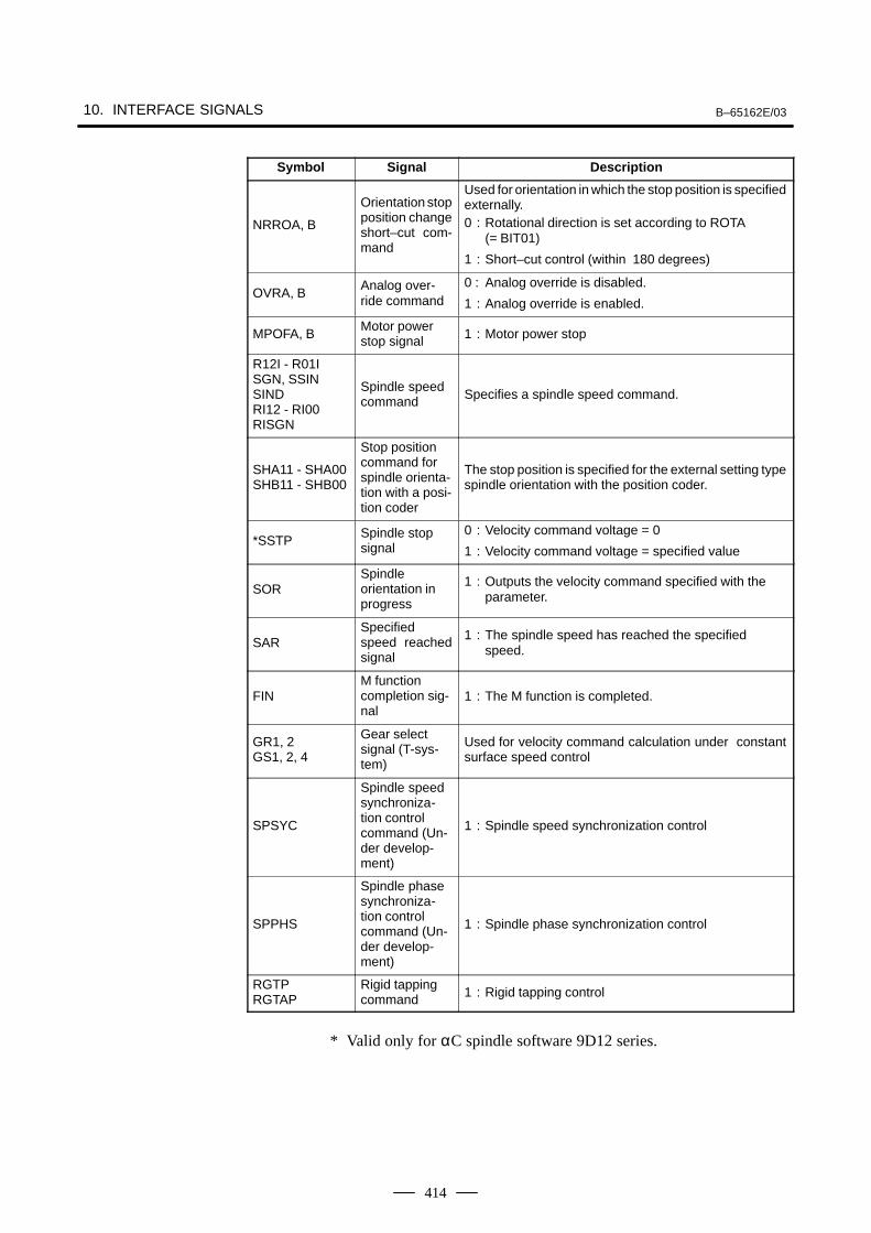
10. INTERFACE SIGNALS B–65162E/03
414
Symbol DescriptionSignal
NRROA, B
Orientation stopposition changeshort–cut com-mand
Used for orientation in which the stop position is specifiedexternally.0 : Rotational direction is set according to ROTA
(= BIT01)
1 : Short–cut control (within 180 degrees)
OVRA, BAnalog over-ride command
0 : Analog override is disabled.
1 : Analog override is enabled.
MPOFA, BMotor powerstop signal 1 : Motor power stop
R12I - R01I SGN, SSIN SINDRI12 - RI00 RISGN
Spindle speedcommand Specifies a spindle speed command.
SHA11 - SHA00SHB11 - SHB00
Stop positioncommand forspindle orienta-tion with a posi-tion coder
The stop position is specified for the external setting typespindle orientation with the position coder.
*SSTPSpindle stopsignal
0 : Velocity command voltage = 0
1 : Velocity command voltage = specified value
SORSpindleorientation inprogress
1 : Outputs the velocity command specified with theparameter.
SARSpecifiedspeed reachedsignal
1 : The spindle speed has reached the specifiedspeed.
FINM functioncompletion sig-nal
1 : The M function is completed.
GR1, 2GS1, 2, 4
Gear selectsignal (T-sys-tem)
Used for velocity command calculation under constantsurface speed control
SPSYC
Spindle speedsynchroniza-tion controlcommand (Un-der develop-ment)
1 : Spindle speed synchronization control
SPPHS
Spindle phasesynchroniza-tion controlcommand (Un-der develop-ment)
1 : Spindle phase synchronization control
RGTPRGTAP
Rigid tappingcommand 1 : Rigid tapping control
* Valid only for αC spindle software 9D12 series.
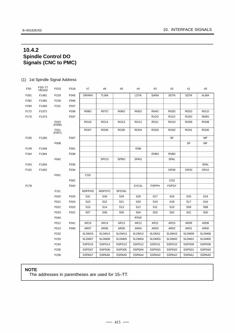
B–65162E/03 10. INTERFACE SIGNALS
415
(1) 1st Spindle Signal Address
FS0 FS0–TTHEAD2 FS15 FS16 #7 #6 #5 #4 #3 #2 #1 #0
F281 F1481 F229 F045 ORARA TLMA LDTA SARA SDTA SSTA ALMA
F282 F1482 F228 F046
F283 F1483 F231 F047
F172 F1372 F036 R08O R07O R06O R05O R04O R03O R02O R01O
F173 F1373 F037 R12O R11O R10O R09O
F010(F006)
RO15 RO14 RO13 RO12 RO11 RO10 RO09 RO08
F011(F007)
RO07 RO06 RO05 RO04 RO03 RO02 RO01 RO00
F150 F1350 F007 SF MF
F008 SF MF
F149 F1349 F001 ENB
F164 F1364 F038 ENB3 ENB2
F042 SPCO SPBO SPAO SPAL
F154 F1354 F035 SPAL
F152 F1352 F034 GR30 GR20 GR10
F001 CSS
F002 CSS
F178 F044 SYCAL FSPPH FSPSY
F111 MSPPHS MSPSYC SPSYAL
F020 F025 S31 S30 S29 S28 S27 S26 S25 S24
F021 F024 S23 S22 S21 S20 S19 S18 S17 S16
F022 F023 S15 S14 S13 S12 S11 S10 S09 S08
F023 F022 S07 S06 S05 S04 S03 S02 S01 S00
F040 RTAP
F012 F041 AR15 AR14 AR13 AR12 AR11 AR10 AR09 AR08
F013 F040 AR07 AR06 AR05 AR04 AR03 AR02 AR01 AR00
F232 SLDM15 SLDM14 SLDM13 SLDM12 SLDM11 SLDM10 SLDM09 SLDM08
F233 SLDM07 SLDM06 SLDM05 SLDM04 SLDM03 SLDM02 SLDM01 SLDM00
F234 SSPD15 SSPD14 SSPD13 SSPD12 SSPD11 SSPD10 SSPD09 SSPD08
F235 SSPD07 SSPD06 SSPD05 SSPD04 SSPD03 SSPD02 SSPD01 SSPD00
F236 SSPAA7 SSPAA6 SSPAA5 SSPAA4 SSPAA3 SSPAA2 SSPAA1 SSPAA0
NOTEThe addresses in parentheses are used for 15–TT.
10.4.2Spindle Control DOSignals (CNC to PMC)
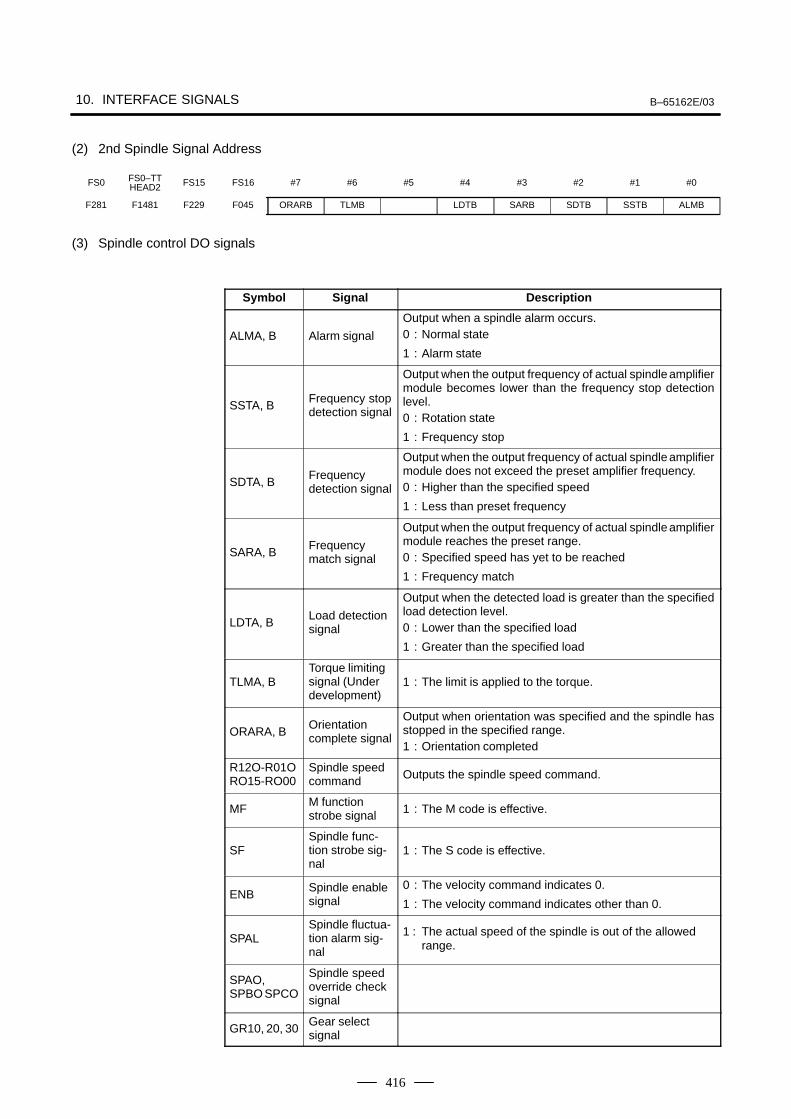
10. INTERFACE SIGNALS B–65162E/03
416
(2) 2nd Spindle Signal Address
FS0 FS0–TTHEAD2 FS15 FS16 #7 #6 #5 #4 #3 #2 #1 #0
F281 F1481 F229 F045 ORARB TLMB LDTB SARB SDTB SSTB ALMB
(3) Spindle control DO signals
Symbol Signal Description
ALMA, B Alarm signal
Output when a spindle alarm occurs.0 : Normal state
1 : Alarm state
SSTA, BFrequency stopdetection signal
Output when the output frequency of actual spindle amplifiermodule becomes lower than the frequency stop detectionlevel.0 : Rotation state
1 : Frequency stop
SDTA, BFrequencydetection signal
Output when the output frequency of actual spindle amplifiermodule does not exceed the preset amplifier frequency.0 : Higher than the specified speed
1 : Less than preset frequency
SARA, BFrequencymatch signal
Output when the output frequency of actual spindle amplifiermodule reaches the preset range.0 : Specified speed has yet to be reached
1 : Frequency match
LDTA, BLoad detectionsignal
Output when the detected load is greater than the specifiedload detection level.0 : Lower than the specified load
1 : Greater than the specified load
TLMA, BTorque limitingsignal (Underdevelopment)
1 : The limit is applied to the torque.
ORARA, BOrientationcomplete signal
Output when orientation was specified and the spindle hasstopped in the specified range.1 : Orientation completed
R12O-R01ORO15-RO00
Spindle speedcommand Outputs the spindle speed command.
MFM functionstrobe signal 1 : The M code is effective.
SFSpindle func-tion strobe sig-nal
1 : The S code is effective.
ENBSpindle enablesignal
0 : The velocity command indicates 0.
1 : The velocity command indicates other than 0.
SPALSpindle fluctua-tion alarm sig-nal
1 : The actual speed of the spindle is out of the allowedrange.
SPAO,SPBO SPCO
Spindle speedoverride checksignal
GR10, 20, 30Gear selectsignal
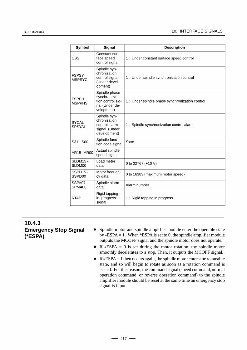
B–65162E/03 10. INTERFACE SIGNALS
417
Symbol DescriptionSignal
CSSConstant sur-face speedcontrol signal
1 : Under constant surface speed control
FSPSYMSPSYC
Spindle syn-chronizationcontrol signal(Under devel-opment)
1 : Under spindle synchronization control
FSPPHMSPPHS
Spindle phasesynchroniza-tion control sig-nal (Under de-velopment)
1 : Under spindle phase synchronization control
SYCALSPSYAL
Spindle syn-chronizationcontrol alarmsignal (Underdevelopment)
1 : Spindle synchronization control alarm
S31 - S00Spindle func-tion code signal Sxxx
AR15 - AR00Actual spindlespeed signal
SLDM15 - SLDM00
Load meterdata 0 to 32767 (+10 V)
SSPD15 - SSPD00
Motor frequen-cy data 0 to 16383 (maximum motor speed)
SSPA07 - SPMA00
Spindle alarmdata Alarm number
RTAPRigid tapping–in–progresssignal
1 : Rigid tapping in progress
Spindle motor and spindle amplifier module enter the operable stateby *ESPA = 1. When *ESPA is set to 0, the spindle amplifier moduleoutputs the MCOFF signal and the spindle motor does not operate.
If *ESPA = 0 is set during the motor rotation, the spindle motorsmoothly decelerates to a stop. Then, it outputs the MCOFF signal.
If *ESPA = 1 then occurs again, the spindle motor enters the rotateablestate, and so will begin to rotate as soon as a rotation command isissued. For this reason, the command signal (speed command, normaloperation command, or reverse operation command) to the spindleamplifier module should be reset at the same time an emergency stopsignal is input.
10.4.3Emergency Stop Signal(*ESPA)
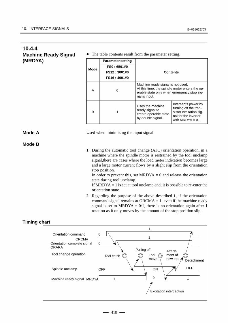
10. INTERFACE SIGNALS B–65162E/03
418
The table contents result from the parameter setting.
Parameter setting
ModeFS0 : 6501#0
FS12 : 3001#0
FS16 : 4001#0
Contents
A 0
Machine ready signal is not used.At this time, the spindle motor enters the op-erable state only when emergency stop sig-nal is input.
B 1
Uses the machineready signal tocreate operable stateby double signal.
Intercepts power byturning off the tran-sistor excitation sig-nal for the inverterwith MRDYA = 0.
Used when minimizing the input signal.
1 During the automatic tool change (ATC) orientation operation, in amachine where the spindle motor is restrained by the tool unclampsignal,there are cases where the load meter indication becomes largeand a large motor current flows by a slight slip from the orientationstop position.In order to prevent this, set MRDYA = 0 and release the orientationstate during tool unclamp.If MRDYA = 1 is set at tool unclamp end, it is possible to re-enter theorientation state.
2 Regarding the purpose of the above described 1, if the orientationcommand signal remains at ORCMA = 1, even if the machine readysignal is set to MRDYA = 0/1, there is no orientation again after 1rotation as it only moves by the amount of the stop position slip.
Orientation commandCRCMA
1
1
1
0
0
Pulling off
Toolmove
10
OFF
Orientation complete signalORARA
Spindle unclamp
Tool change operation
Excitation interception
Tool catchDetachment
Attach-ment ofnew tool
MRDYAMachine ready signal
ON OFF
10.4.4Machine Ready Signal(MRDYA)
Mode A
Mode B
Timing chart

B–65162E/03 10. INTERFACE SIGNALS
419
When the following four conditions hold, the spindle motor starts anormal rotation corresponding to the speed command (positive value).
During acceleration/deceleration (before a specified speed is reached),the motor speed increases or decreases according to anacceleration/deceleration constant specified in the parameters listedbelow. The acceleration/deceleration constant can take four differentvalues depending on the clutch/gear signals (CTH1 and CTH2).
Emergency stop signal *ESPA is 1
Machine ready signal MRDYA is 1
Normal rotation command signal SFRA is 1
Contact signal ESP is connected to 24 V (at CX4 of the PSM)
Parameter DI signal
FS0 FS15 FS16 CTH1A
CTH2A
Contents
65696709
30693209 4069 0 0
An acceleration/decelerationconstant is specified. It cantake four different values de-pending on the CTH1 and
65706710
30703210 4070 0 1
pending on the CTH1 andCTH2 signals.Unit : 1rpm/sec(Series16: 10 rpm unit when
65716711
30713211 4071 1 0
(4006#bit2=1)Data range : 0 to 32767(Motor does not rotate when 0 isset)
65726712
30723212 4072 1 1
set)Standard setting : Depends onmotor model (Initial setting=900)
While SFRA = 1, the spindle motor rotates in the counterclockwisedirection (CCW) viewed from the shaft side according to thecommanded speed (positive value).
If SFRA = 0 occurs, the spindle motor stops by the regenerativebraking. After stopping, it cuts the power supply to the spindle motorby intercepting the transistor excitation signal.
10.4.5Normal RotationCommand Signal(SFRA)
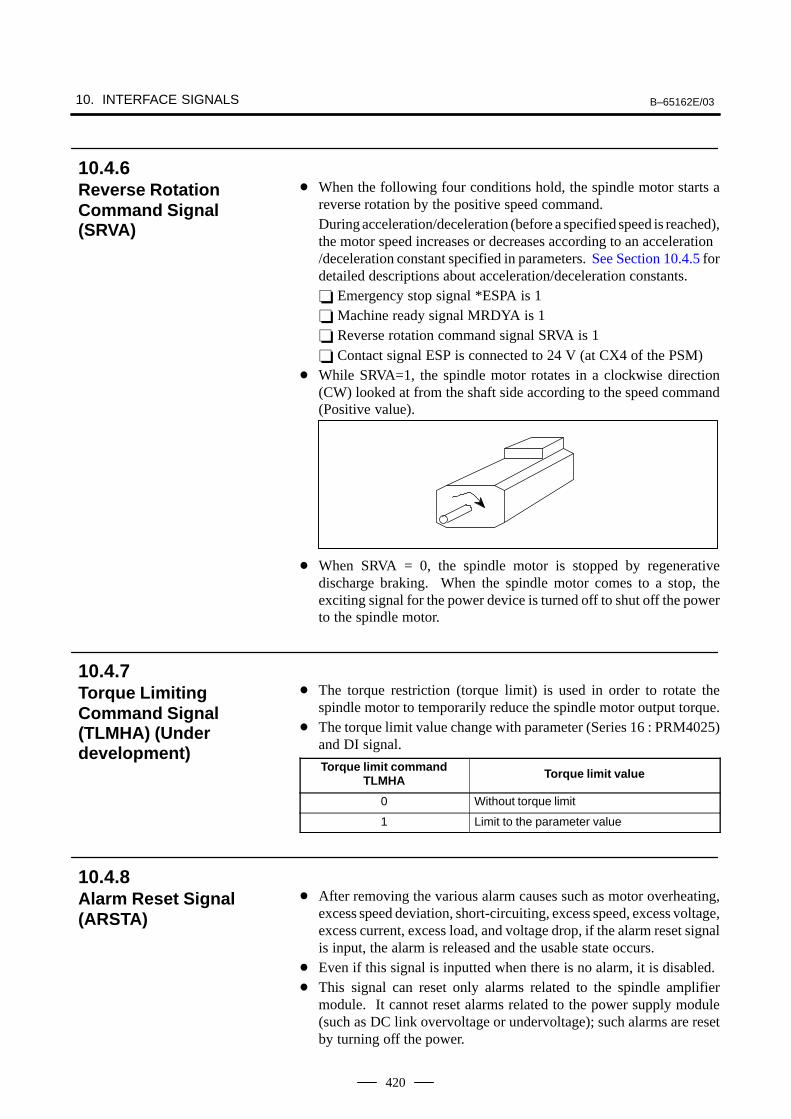
10. INTERFACE SIGNALS B–65162E/03
420
When the following four conditions hold, the spindle motor starts areverse rotation by the positive speed command.During acceleration/deceleration (before a specified speed is reached),the motor speed increases or decreases according to an acceleration/deceleration constant specified in parameters. See Section 10.4.5 fordetailed descriptions about acceleration/deceleration constants. Emergency stop signal *ESPA is 1 Machine ready signal MRDYA is 1 Reverse rotation command signal SRVA is 1 Contact signal ESP is connected to 24 V (at CX4 of the PSM)
While SRVA=1, the spindle motor rotates in a clockwise direction(CW) looked at from the shaft side according to the speed command(Positive value).
When SRVA = 0, the spindle motor is stopped by regenerativedischarge braking. When the spindle motor comes to a stop, theexciting signal for the power device is turned off to shut off the powerto the spindle motor.
The torque restriction (torque limit) is used in order to rotate thespindle motor to temporarily reduce the spindle motor output torque.
The torque limit value change with parameter (Series 16 : PRM4025)and DI signal.
Torque limit commandTLMHA Torque limit value
0 Without torque limit
1 Limit to the parameter value
After removing the various alarm causes such as motor overheating,excess speed deviation, short-circuiting, excess speed, excess voltage,excess current, excess load, and voltage drop, if the alarm reset signalis input, the alarm is released and the usable state occurs.
Even if this signal is inputted when there is no alarm, it is disabled. This signal can reset only alarms related to the spindle amplifier
module. It cannot reset alarms related to the power supply module(such as DC link overvoltage or undervoltage); such alarms are resetby turning off the power.
10.4.6Reverse RotationCommand Signal(SRVA)
10.4.7Torque LimitingCommand Signal(TLMHA) (Underdevelopment)
10.4.8Alarm Reset Signal(ARSTA)
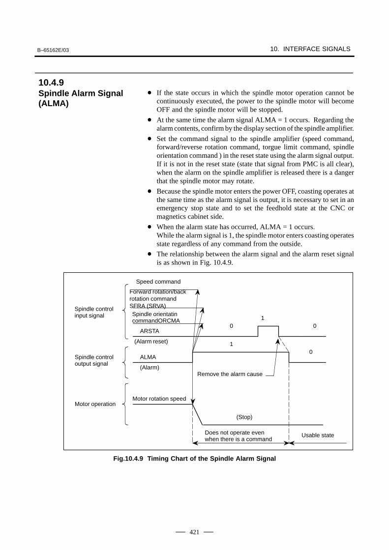
B–65162E/03 10. INTERFACE SIGNALS
421
If the state occurs in which the spindle motor operation cannot becontinuously executed, the power to the spindle motor will becomeOFF and the spindle motor will be stopped.
At the same time the alarm signal ALMA = 1 occurs. Regarding thealarm contents, confirm by the display section of the spindle amplifier.
Set the command signal to the spindle amplifier (speed command,forward/reverse rotation command, torgue limit command, spindleorientation command ) in the reset state using the alarm signal output.If it is not in the reset state (state that signal from PMC is all clear),when the alarm on the spindle amplifier is released there is a dangerthat the spindle motor may rotate.
Because the spindle motor enters the power OFF, coasting operates atthe same time as the alarm signal is output, it is necessary to set in anemergency stop state and to set the feedhold state at the CNC ormagnetics cabinet side.
When the alarm state has occurred, ALMA = 1 occurs.While the alarm signal is 1, the spindle motor enters coasting operatesstate regardless of any command from the outside.
The relationship between the alarm signal and the alarm reset signalis as shown in Fig. 10.4.9.
Forward rotation/backrotation commandSFRA (SRVA)
1
10
(Stop)
Motor rotation speed
Does not operate evenwhen there is a command
Usable state
Motor operation
Spindle controloutput signal
Spindle control input signal
0
Remove the alarm cause
(Alarm reset)
Speed command
ARSTA
(Alarm)
ALMA
0
Spindle orientatincommandORCMA
Fig.10.4.9 Timing Chart of the Spindle Alarm Signal
10.4.9Spindle Alarm Signal(ALMA)
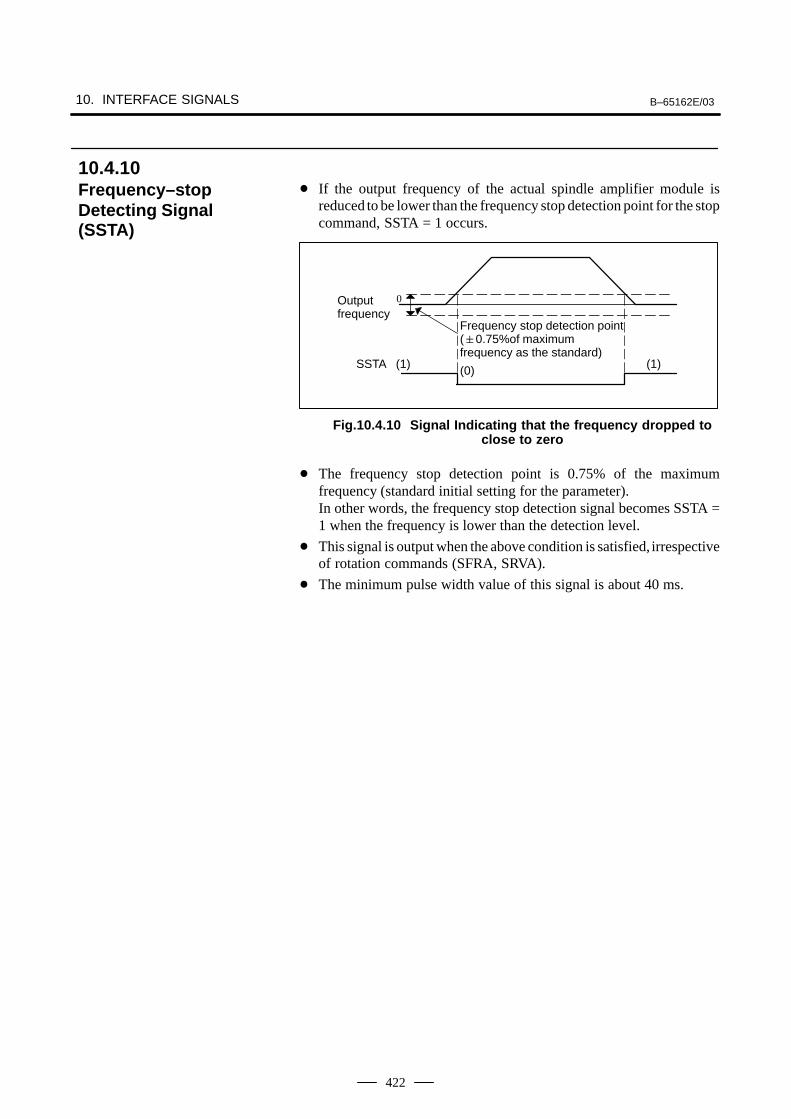
10. INTERFACE SIGNALS B–65162E/03
422
If the output frequency of the actual spindle amplifier module isreduced to be lower than the frequency stop detection point for the stopcommand, SSTA = 1 occurs.
Frequency stop detection point(0.75%of maximum frequency as the standard)
(0)
0
SSTA (1) (1)
Outputfrequency
Fig.10.4.10 Signal Indicating that the frequency dropped toclose to zero
The frequency stop detection point is 0.75% of the maximumfrequency (standard initial setting for the parameter).In other words, the frequency stop detection signal becomes SSTA =1 when the frequency is lower than the detection level.
This signal is output when the above condition is satisfied, irrespectiveof rotation commands (SFRA, SRVA).
The minimum pulse width value of this signal is about 40 ms.
10.4.10Frequency–stopDetecting Signal(SSTA)
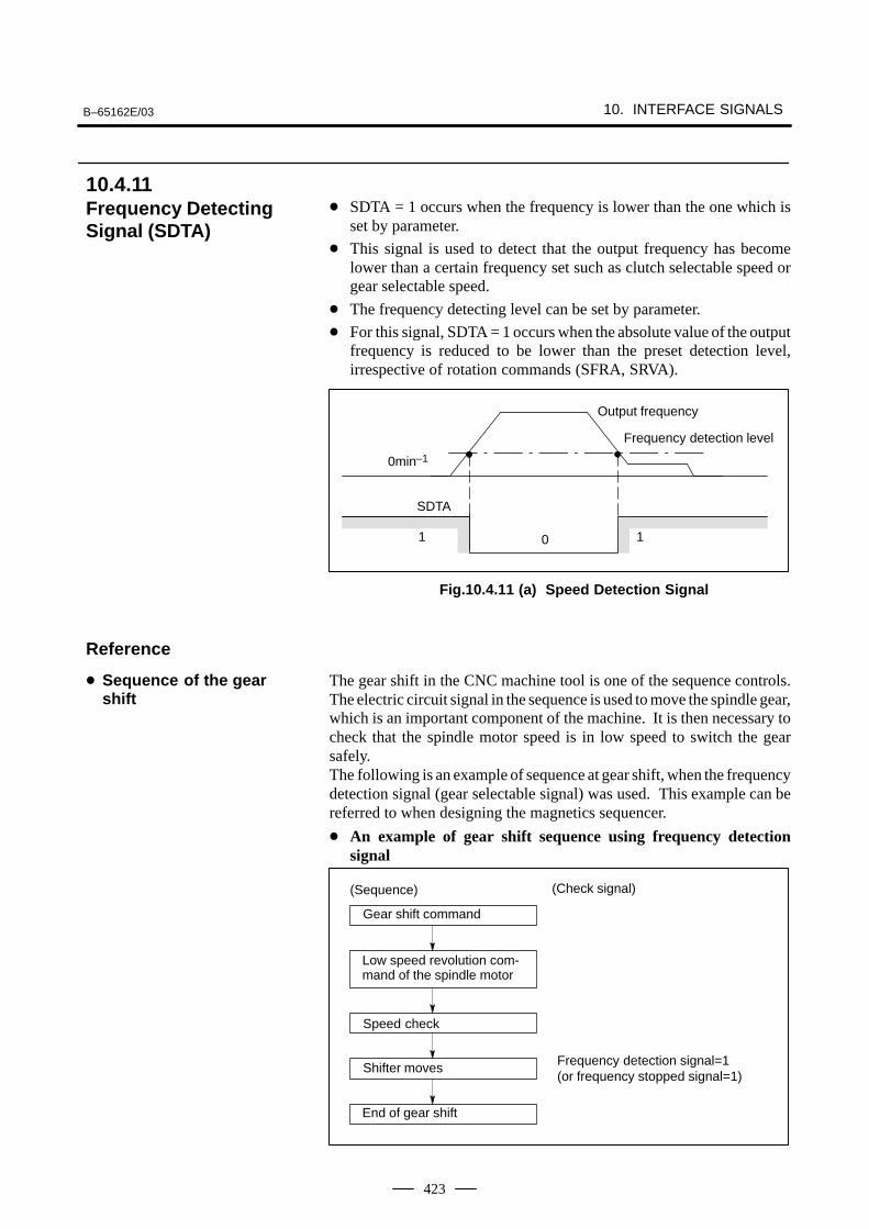
B–65162E/03 10. INTERFACE SIGNALS
423
SDTA = 1 occurs when the frequency is lower than the one which isset by parameter.
This signal is used to detect that the output frequency has becomelower than a certain frequency set such as clutch selectable speed orgear selectable speed.
The frequency detecting level can be set by parameter.
For this signal, SDTA = 1 occurs when the absolute value of the outputfrequency is reduced to be lower than the preset detection level,irrespective of rotation commands (SFRA, SRVA).
0
SDTA
1
Frequency detection level
1
0min–1
Output frequency
Fig.10.4.11 (a) Speed Detection Signal
The gear shift in the CNC machine tool is one of the sequence controls.The electric circuit signal in the sequence is used to move the spindle gear,which is an important component of the machine. It is then necessary tocheck that the spindle motor speed is in low speed to switch the gearsafely.The following is an example of sequence at gear shift, when the frequencydetection signal (gear selectable signal) was used. This example can bereferred to when designing the magnetics sequencer.
An example of gear shift sequence using frequency detectionsignal
Frequency detection signal=1(or frequency stopped signal=1)
(Sequence) (Check signal)
Low speed revolution com-mand of the spindle motor
Speed check
Shifter moves
End of gear shift
Gear shift command
10.4.11Frequency DetectingSignal (SDTA)
Reference
Sequence of the gearshift
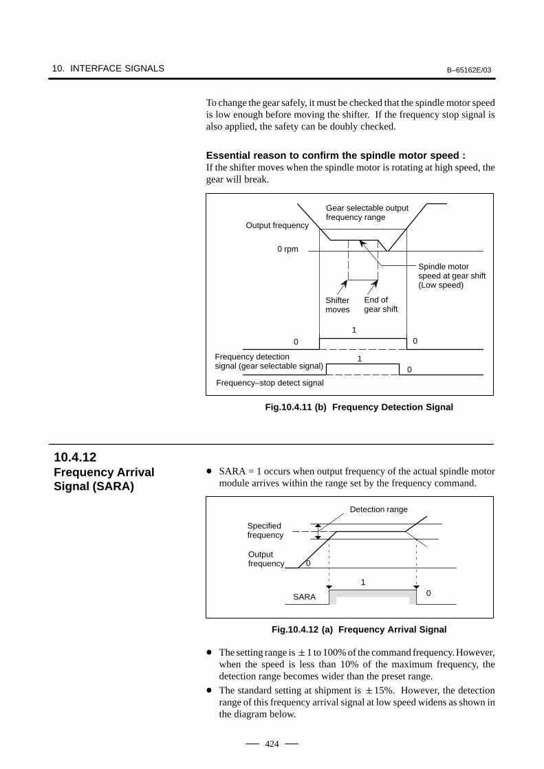
10. INTERFACE SIGNALS B–65162E/03
424
To change the gear safely, it must be checked that the spindle motor speedis low enough before moving the shifter. If the frequency stop signal isalso applied, the safety can be doubly checked.
Essential reason to confirm the spindle motor speed :If the shifter moves when the spindle motor is rotating at high speed, thegear will break.
1
Gear selectable outputfrequency range
Frequency–stop detect signal
Frequency detection signal (gear selectable signal)
Output frequency
0
Spindle motorspeed at gear shift(Low speed)
0 rpm
Shiftermoves
0
End ofgear shift
10
Fig.10.4.11 (b) Frequency Detection Signal
SARA = 1 occurs when output frequency of the actual spindle motormodule arrives within the range set by the frequency command.
1
Specifiedfrequency
0
Detection range
SARA
Output frequency 0
Fig.10.4.12 (a) Frequency Arrival Signal
The setting range is 1 to 100% of the command frequency. However,when the speed is less than 10% of the maximum frequency, thedetection range becomes wider than the preset range.
The standard setting at shipment is 15%. However, the detectionrange of this frequency arrival signal at low speed widens as shown inthe diagram below.
10.4.12Frequency ArrivalSignal (SARA)
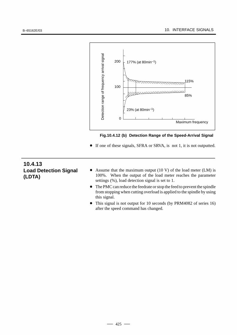
B–65162E/03 10. INTERFACE SIGNALS
425
0
100
200
Maximum frequency
115%
85%
177% (at 80min–1)
23% (at 80min–1)
Det
ectio
n ra
nge
of fr
eque
ncy
arriv
al s
igna
l
Fig.10.4.12 (b) Detection Range of the Speed-Arrival Signal
If one of these signals, SFRA or SRVA, is not 1, it is not outputted.
Assume that the maximum output (10 V) of the load meter (LM) is100%. When the output of the load meter reaches the parametersettings (%), load detection signal is set to 1.
The PMC can reduce the feedrate or stop the feed to prevent the spindlefrom stopping when cutting overload is applied to the spindle by usingthis signal.
This signal is not output for 10 seconds (by PRM4082 of series 16)after the speed command has changed.
10.4.13Load Detection Signal(LDTA)
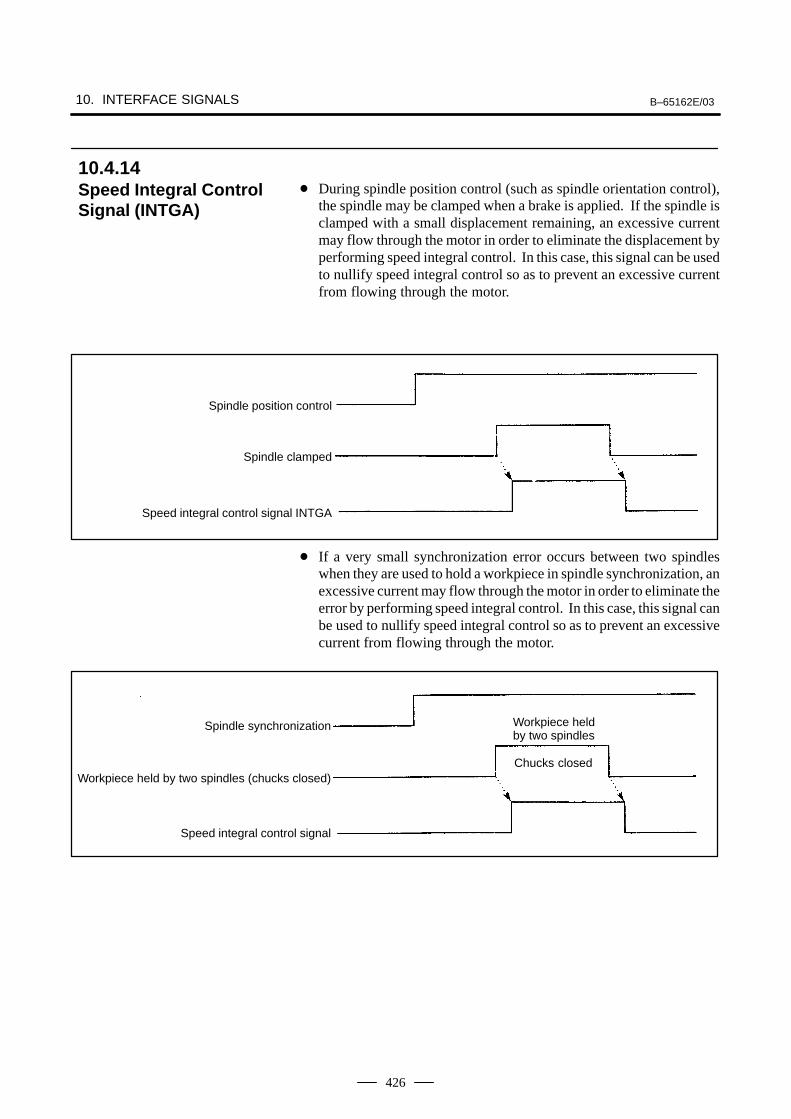
10. INTERFACE SIGNALS B–65162E/03
426
During spindle position control (such as spindle orientation control),the spindle may be clamped when a brake is applied. If the spindle isclamped with a small displacement remaining, an excessive currentmay flow through the motor in order to eliminate the displacement byperforming speed integral control. In this case, this signal can be usedto nullify speed integral control so as to prevent an excessive currentfrom flowing through the motor.
Spindle position control
Spindle clamped
Speed integral control signal INTGA
If a very small synchronization error occurs between two spindleswhen they are used to hold a workpiece in spindle synchronization, anexcessive current may flow through the motor in order to eliminate theerror by performing speed integral control. In this case, this signal canbe used to nullify speed integral control so as to prevent an excessivecurrent from flowing through the motor.
Spindle synchronization Workpiece heldby two spindles
Workpiece held by two spindles (chucks closed)Chucks closed
Speed integral control signal
10.4.14Speed Integral ControlSignal (INTGA)
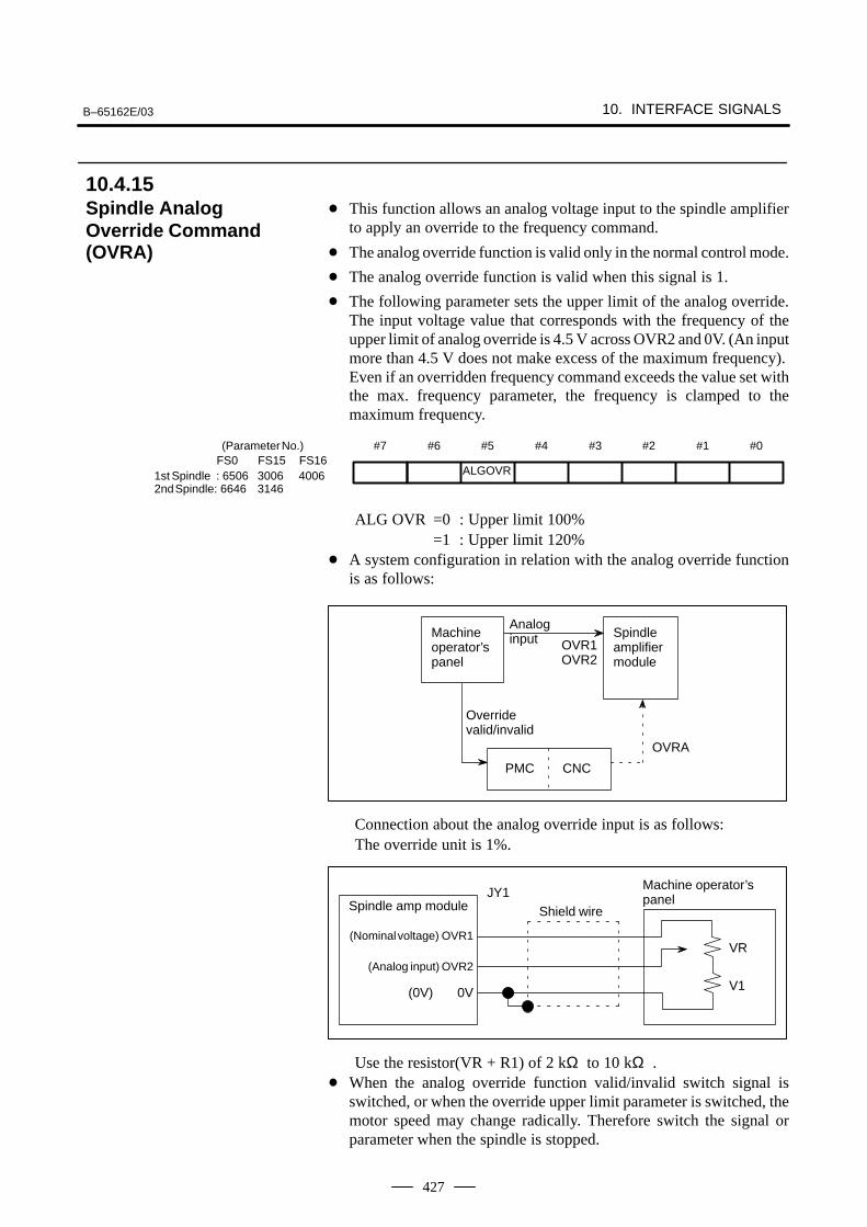
B–65162E/03 10. INTERFACE SIGNALS
427
This function allows an analog voltage input to the spindle amplifierto apply an override to the frequency command.
The analog override function is valid only in the normal control mode.
The analog override function is valid when this signal is 1.
The following parameter sets the upper limit of the analog override.The input voltage value that corresponds with the frequency of theupper limit of analog override is 4.5 V across OVR2 and 0V. (An inputmore than 4.5 V does not make excess of the maximum frequency).Even if an overridden frequency command exceeds the value set withthe max. frequency parameter, the frequency is clamped to themaximum frequency.
#7 #6 #5
ALGOVR
#4 #3 #2 #1 #0
1st Spindle : 6506 3006 40062nd Spindle: 6646 3146
FS0 FS15 FS16(Parameter No.)
ALG OVR =0 : Upper limit 100%=1 : Upper limit 120%
A system configuration in relation with the analog override functionis as follows:
Machineoperator’spanel
Spindleamplifiermodule
Analoginput OVR1
OVR2
Overridevalid/invalid
PMC CNC
OVRA
Connection about the analog override input is as follows:The override unit is 1%.
Spindle amp moduleJY1
(Nominal voltage) OVR1
(Analog input) OVR2
(0V) 0V
Shield wire
Machine operator’spanel
VR
V1
Use the resistor(VR + R1) of 2 kΩ to 10 kΩ . When the analog override function valid/invalid switch signal is
switched, or when the override upper limit parameter is switched, themotor speed may change radically. Therefore switch the signal orparameter when the spindle is stopped.
10.4.15Spindle AnalogOverride Command(OVRA)
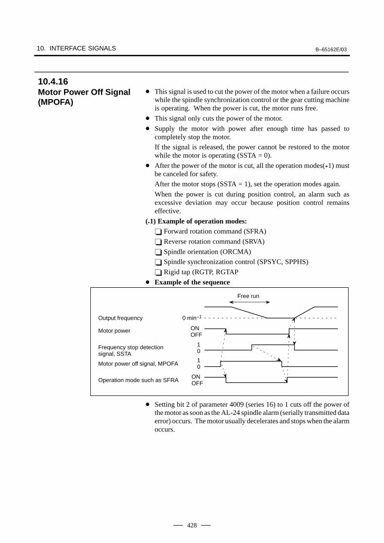
10. INTERFACE SIGNALS B–65162E/03
428
This signal is used to cut the power of the motor when a failure occurswhile the spindle synchronization control or the gear cutting machineis operating. When the power is cut, the motor runs free.
This signal only cuts the power of the motor.
Supply the motor with power after enough time has passed tocompletely stop the motor.
If the signal is released, the power cannot be restored to the motorwhile the motor is operating (SSTA = 0).
After the power of the motor is cut, all the operation modes(*1) mustbe canceled for safety.
After the motor stops (SSTA = 1), set the operation modes again.
When the power is cut during position control, an alarm such asexcessive deviation may occur because position control remainseffective.
(*1) Example of operation modes: Forward rotation command (SFRA)
Reverse rotation command (SRVA)
Spindle orientation (ORCMA)
Spindle synchronization control (SPSYC, SPPHS)
Rigid tap (RGTP, RGTAP
Example of the sequence
Output frequency
Motor power
Frequency stop detection signal, SSTA
Motor power off signal, MPOFA
Operation mode such as SFRA
0 min–1
Free run
ONOFF
10
10
ONOFF
Setting bit 2 of parameter 4009 (series 16) to 1 cuts off the power ofthe motor as soon as the AL-24 spindle alarm (serially transmitted dataerror) occurs. The motor usually decelerates and stops when the alarmoccurs.
10.4.16Motor Power Off Signal(MPOFA)
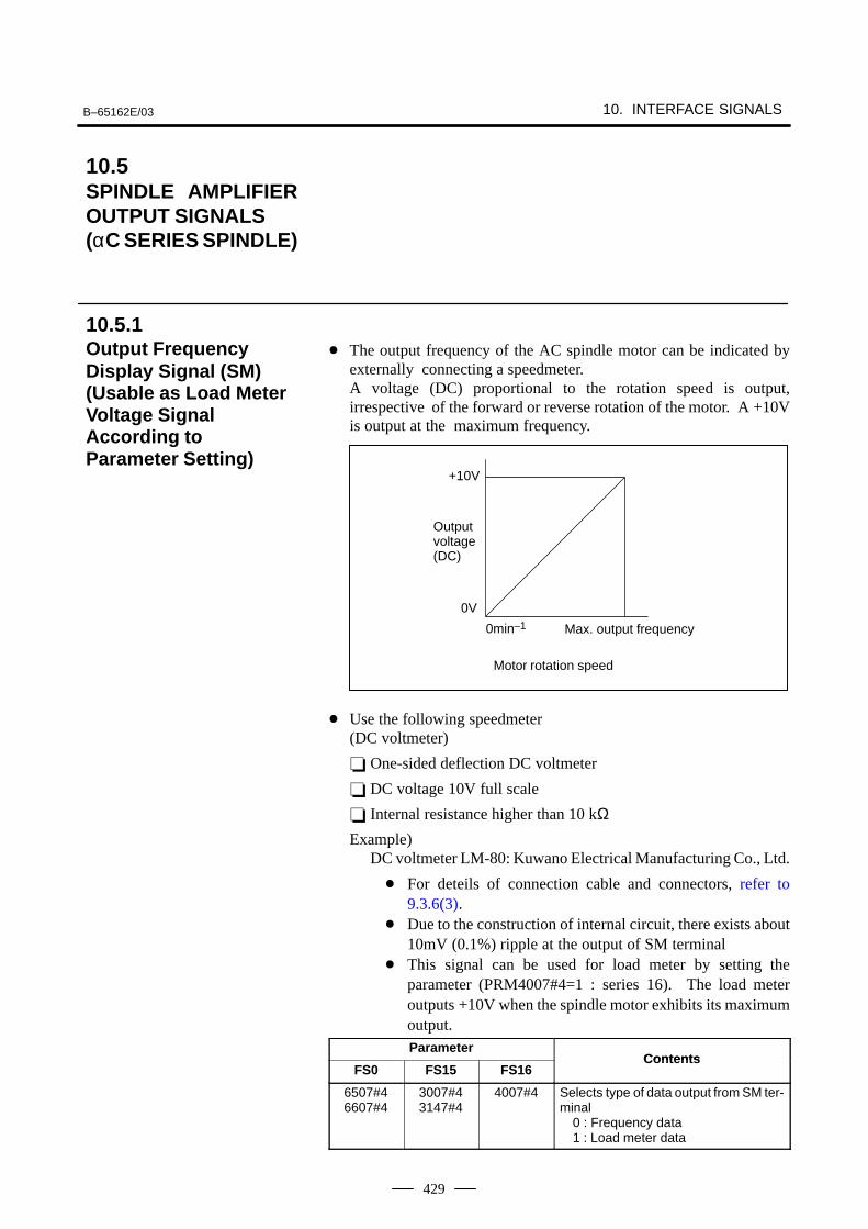
B–65162E/03 10. INTERFACE SIGNALS
429
The output frequency of the AC spindle motor can be indicated byexternally connecting a speedmeter.A voltage (DC) proportional to the rotation speed is output,irrespective of the forward or reverse rotation of the motor. A +10Vis output at the maximum frequency.
+10V
0V
0min–1
Outputvoltage(DC)
Motor rotation speed
Max. output frequency
Use the following speedmeter(DC voltmeter)
One-sided deflection DC voltmeter
DC voltage 10V full scale
Internal resistance higher than 10 kΩExample)
DC voltmeter LM-80: Kuwano Electrical Manufacturing Co., Ltd.
For deteils of connection cable and connectors, refer to9.3.6(3).
Due to the construction of internal circuit, there exists about10mV (0.1%) ripple at the output of SM terminal
This signal can be used for load meter by setting theparameter (PRM4007#4=1 : series 16). The load meteroutputs +10V when the spindle motor exhibits its maximumoutput.Parameter
ContentsFS0 FS15 FS16
Contents
6507#46607#4
3007#43147#4
4007#4 Selects type of data output from SM ter-minal
0 : Frequency data1 : Load meter data
10.5SPINDLE AMPLIFIEROUTPUT SIGNALS (αC SERIES SPINDLE)
10.5.1Output FrequencyDisplay Signal (SM)(Usable as Load MeterVoltage SignalAccording toParameter Setting)
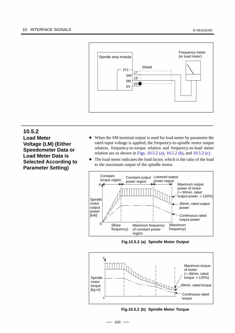
10. INTERFACE SIGNALS B–65162E/03
430
Spindle amp module
JY1
SM
0M
0V
Shield
17
19
20
Frequency meter (or load meter)
When the SM terminal output is used for load meter by parameter therated input voltage is applied, the frequency-to-spindle motor outputrelation, frequency-to-torque relation and frequency-to-load meterrelation are as shown in Figs. 10.5.2 (a), 10.5.2 (b), and 10.5.2 (c).
The load meter indicates the load factor, which is the ratio of the loadto the maximum output of the spindle motor.
Lowered outputpower region
Constanttorque region
Constant outputpower region
30min. rated outputpower
Continuous ratedoutput power
(Base frequency)
(Maximumfrequency)
P
0
Maximum output power of motor(30min. rated output power 120%)
Spindlemotoroutputpower[kW]
Maximum frequency of constant power region
Fig.10.5.2 (a) Spindle Motor Output
Maximum torqueof motor(30min. ratedtorque 120%)
30min. rated torque
Continuous ratedtorque
T
0
Spindlemotortorque[kg·m]
Fig.10.5.2 (b) Spindle Motor Torque
10.5.2Load Meter Voltage (LM) (EitherSpeedometer Data orLoad Meter Data isSelected According toParameter Setting)
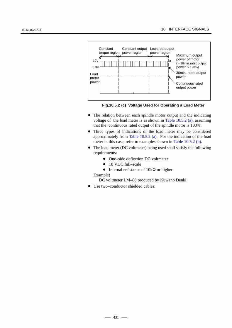
B–65162E/03 10. INTERFACE SIGNALS
431
10V
Maximum outputpower of motor(30min. rated outputpower 120%)
30min. rated outputpower
Continuous ratedoutput power
8.3V
Lowered outputpower region
Constanttorque region
Constant outputpower region
Load meter power
Fig.10.5.2 (c) Voltage Used for Operating a Load Meter
The relation between each spindle motor output and the indicatingvoltage of the load meter is as shown in Table 10.5.2 (a), assumingthat the continuous rated output of the spindle motor is 100%.
Three types of indications of the load meter may be consideredapproximately from Table 10.5.2 (a). For the indication of the loadmeter in this case, refer to examples shown in Table 10.5.2 (b).
The load meter (DC voltmeter) being used shall satisfy the followingrequirements:
One–side deflection DC voltmeter 10 VDC full–scale Internal resistance of 10kΩ or higher
Example)DC voltmeter LM–80 produced by Kuwano Denki
Use two–conductor shielded cables.
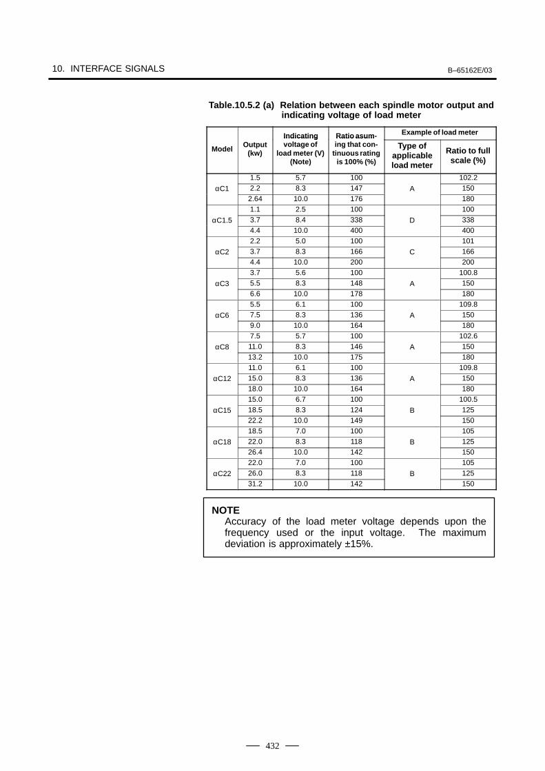
10. INTERFACE SIGNALS B–65162E/03
432
Table.10.5.2 (a) Relation between each spindle motor output andindicating voltage of load meter
Indicating Ratio asum- Example of load meter
ModelOutput
(kw)
Indicatingvoltage of
load meter (V)(Note)
Ratio asuming that con-
tinuous ratingis 100% (%)
Type ofapplicableload meter
Ratio to fullscale (%)
1.5 5.7 100 102.2
αC1 2.2 8.3 147 A 1502.64 10.0 176 1801.1 2.5 100 100
αC1.5 3.7 8.4 338 D 3384.4 10.0 400 4002.2 5.0 100 101
αC2 3.7 8.3 166 C 1664.4 10.0 200 2003.7 5.6 100 100.8
αC3 5.5 8.3 148 A 1506.6 10.0 178 1805.5 6.1 100 109.8
αC6 7.5 8.3 136 A 1509.0 10.0 164 1807.5 5.7 100 102.6
αC8 11.0 8.3 146 A 15013.2 10.0 175 18011.0 6.1 100 109.8
αC12 15.0 8.3 136 A 15018.0 10.0 164 18015.0 6.7 100 100.5
αC15 18.5 8.3 124 B 12522.2 10.0 149 15018.5 7.0 100 105
αC18 22.0 8.3 118 B 12526.4 10.0 142 15022.0 7.0 100 105
αC22 26.0 8.3 118 B 12531.2 10.0 142 150
NOTEAccuracy of the load meter voltage depends upon thefrequency used or the input voltage. The maximumdeviation is approximately ±15%.
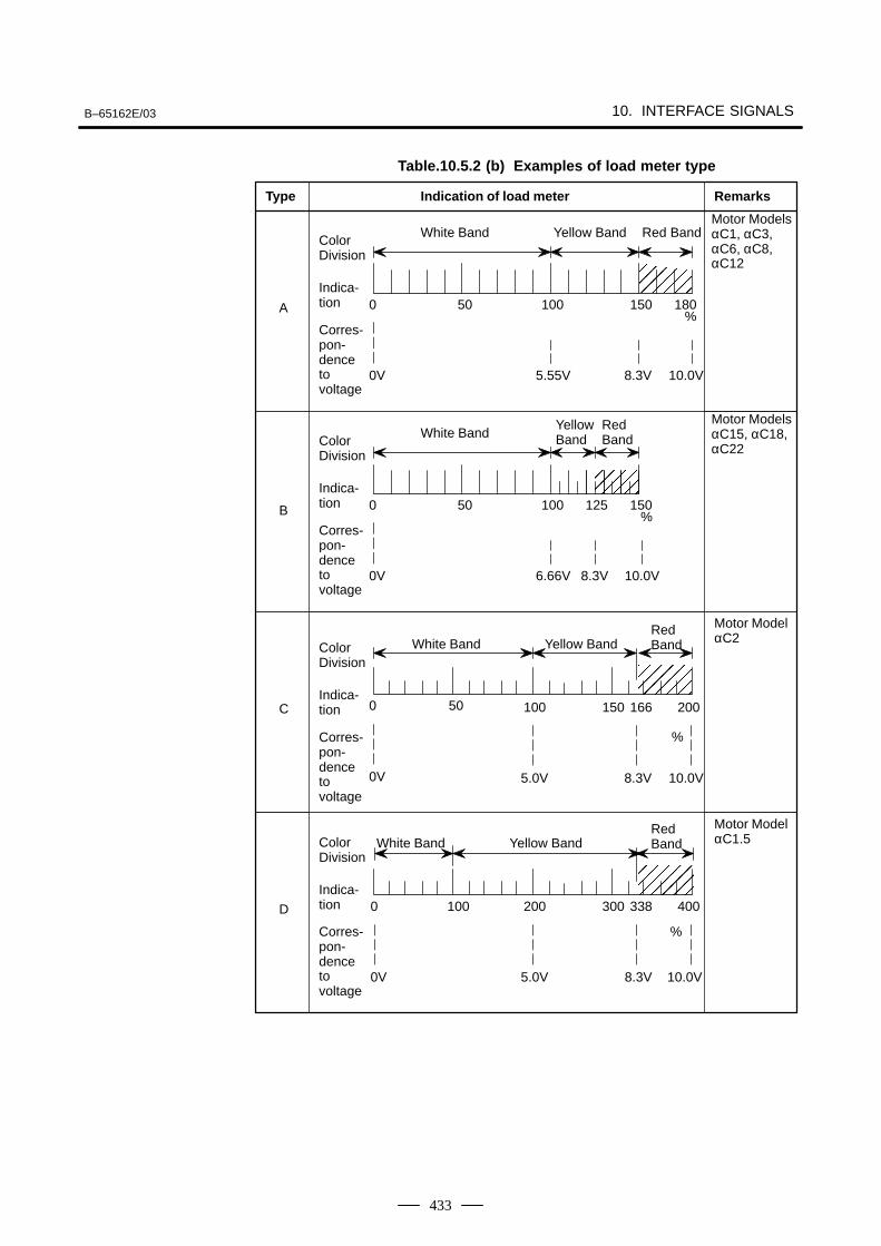
B–65162E/03 10. INTERFACE SIGNALS
433
ÅÅÅÅÅÅ
ÅÅÅÅÅÅÅÅÅ
ÅÅÅÅÅÅÅÅ
White BandYellow Band
Red Band
Type Indication of load meter Remarks
Motor ModelsαC1, αC3,αC6, αC8,αC12
A
B 0 50 100 150125
0V 6.66V 8.3V 10.0V
%
Table.10.5.2 (b) Examples of load meter type
Motor ModelαC2
C
D
Motor ModelαC1.5
0 50 100 200
0V 5.0V 8.3V
%
166
0 100 200 300 400
0V 5.0V 8.3V 10.0V
338
150
10.0V
Corres-pon-denceto voltage
ColorDivision
Indica-tion
White Band Yellow BandRedBand
Corres-pon-denceto voltage
ColorDivision
Indica-tion
Corres-pon-denceto voltage
ColorDivision
Indica-tion
White Band Yellow BandRedBand
%
ÅÅÅÅÅÅÅÅÅ
White Band Yellow Band Red Band
Motor ModelsαC15, αC18,αC22
0 50 100 150 180
0V 5.55V 8.3V 10.0V
%Corres-pon-denceto voltage
ColorDivision
Indica-tion

11. OPTION RELATED TO SPINDLE B–65162E/03
434
11
B–65162E/03 11. OPTION RELATED TO SPINDLE
435
Unlike conventional mechanical spindle orientation using a stopper, etc.,the spindle orientation stops the spindle at a fixed position by directlyfeeding back position signals from the position coder directly connectedto the machine spindle.
This orientation is accomplished simply by connecting the position coderto the spindle without any need of mechanical orientation mechanism(stopper, pin, etc.) for spindle orientation.
Since the spindle motor connected to the spindle is utilized and theorientation can be performed directly from high-speed rotation,irrespective of gear shift, the orientation time is largely reduced.
This sequence consists of the spindle orientation command, itscompletion signal, spindle clutch/gear only without any need of othersignals. Neither orientation speed command sequence nor torque limitcommand sequence is needed.
Electrical system assures improved reliability without any damage to themechanical section against an external impact.
The spindle orientation accuracy and rigidity are enough to executeautomatic tool exchange (ATC).
Workpieces can be positioned to arrange their loading and unloadingdirections in lathe.
Since the spindle orientation can be done in the same direction as therotating direction of the spindle when boring ends, workpieces will notbe damaged by tool blades.Since these tool blades can be mounted or dismounted in a fixed directionwith reference to the workpieces, programming is easy.
11.1SPINDLEORIENTATION
11.1.1Position Coder MethedSpindle Orientation ( αCSeries Spindle)
11.1.1.1General
11.1.1.2Features
Mechanical parts are notrequired.
Reduction of orientationtime
Simplified powermagnetic sequencecontrol
High reliability
High accuracy andrigidity
Positioning of workpiece
Reduction of the numberof processes in boring
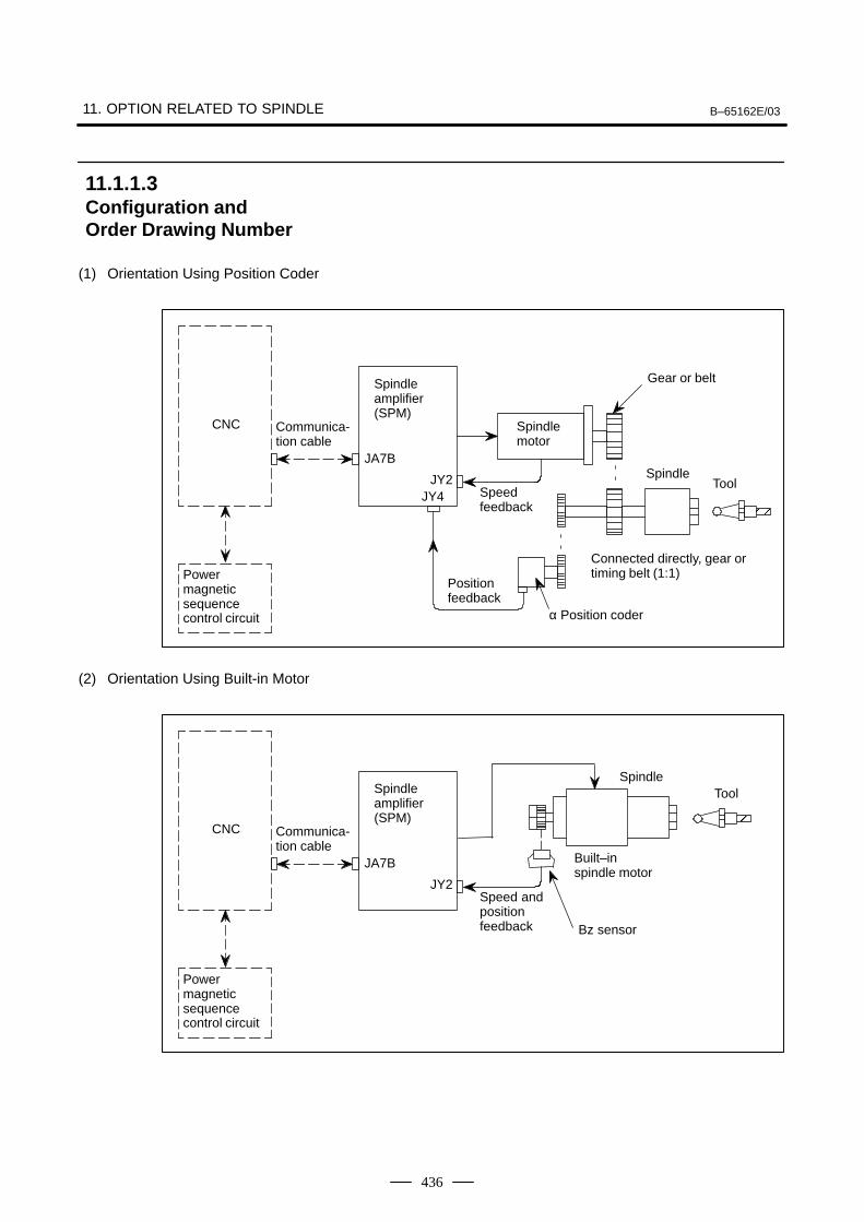
11. OPTION RELATED TO SPINDLE B–65162E/03
436
(1) Orientation Using Position Coder
Communica-tion cable
Powermagneticsequencecontrol circuit
CNC
Spindle amplifier(SPM)
Spindle motor
Gear or belt
α Position coder
Positionfeedback
Speedfeedback
JY4
SpindleTool
ÅÅ
Connected directly, gear ortiming belt (1:1)
JA7B
JY2
(2) Orientation Using Built-in Motor
Communica-tion cable
Powermagneticsequencecontrol circuit
CNC
Spindle amplifier(SPM)
Speed andpositionfeedback
SpindleTool
ÅÅ
JA7B
JY2
Built–in spindle motor
Bz sensor
11.1.1.3Configuration andOrder Drawing Number
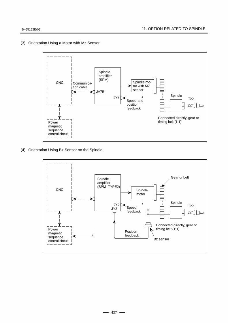
B–65162E/03 11. OPTION RELATED TO SPINDLE
437
(3) Orientation Using a Motor with Mz Sensor
Communica-tion cable
Powermagneticsequencecontrol circuit
CNC
Spindle amplifier(SPM)
Spindle mo-tor with MZsensor
Speed andpositionfeedback
SpindleTool
ÅÅ
JA7B
JY2
Connected directly, gear ortiming belt (1:1)
(4) Orientation Using Bz Sensor on the Spindle
Powermagneticsequencecontrol circuit
CNC
Spindle amplifier(SPM–TYPE2)
Spindle motor
Gear or belt
Bz sensor
Positionfeedback
Speedfeedback
JY2
SpindleTool
ÅÅ
Connected directly, gear ortiming belt (1:1)
JY5
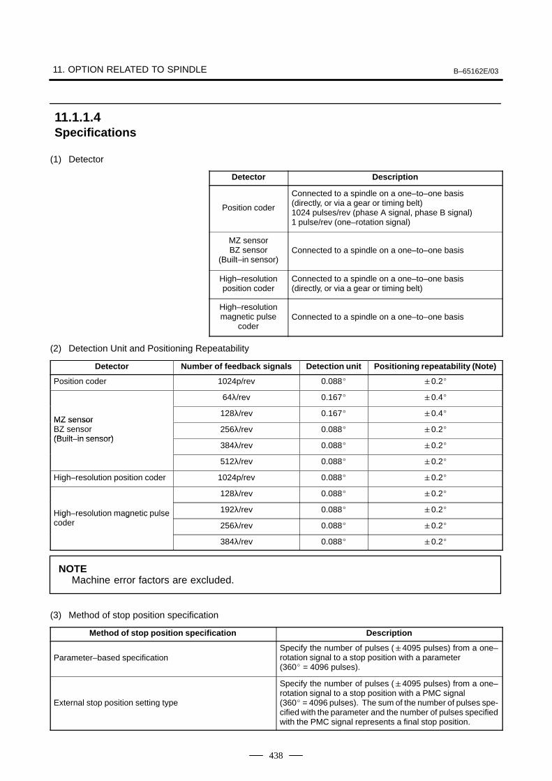
11. OPTION RELATED TO SPINDLE B–65162E/03
438
(1) Detector
Detector Description
Position coder
Connected to a spindle on a one–to–one basis (directly, or via a gear or timing belt)1024 pulses/rev (phase A signal, phase B signal)1 pulse/rev (one–rotation signal)
MZ sensorBZ sensor
(Built–in sensor)Connected to a spindle on a one–to–one basis
High–resolutionposition coder
Connected to a spindle on a one–to–one basis (directly, or via a gear or timing belt)
High–resolutionmagnetic pulse
coderConnected to a spindle on a one–to–one basis
(2) Detection Unit and Positioning Repeatability
Detector Number of feedback signals Detection unit Positioning repeatability (Note)
Position coder 1024p/rev 0.088 0.2
64λ/rev 0.167 0.4
MZ sensor128λ/rev 0.167 0.4
MZ sensorBZ sensor(Built in sensor)
256λ/rev 0.088 0.2(Built–in sensor)
384λ/rev 0.088 0.2
512λ/rev 0.088 0.2
High–resolution position coder 1024p/rev 0.088 0.2
128λ/rev 0.088 0.2
High–resolution magnetic pulse 192λ/rev 0.088 0.2High resolution magnetic ulsecoder 256λ/rev 0.088 0.2
384λ/rev 0.088 0.2
NOTEMachine error factors are excluded.
(3) Method of stop position specification
Method of stop position specification Description
Parameter–based specificationSpecify the number of pulses (4095 pulses) from a one–rotation signal to a stop position with a parameter (360 = 4096 pulses).
External stop position setting type
Specify the number of pulses (4095 pulses) from a one–rotation signal to a stop position with a PMC signal (360 = 4096 pulses). The sum of the number of pulses spe-cified with the parameter and the number of pulses specifiedwith the PMC signal represents a final stop position.
11.1.1.4Specifications
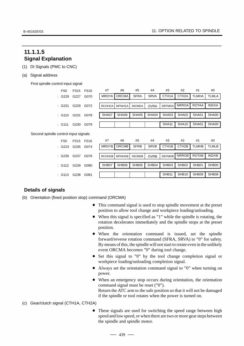
B–65162E/03 11. OPTION RELATED TO SPINDLE
439
(1) DI Signals (PMC to CNC)
(a) Signal address
#7
SHA07
#6
SHA06
#5
SHA05
#4
SHA04
#3
SHA03
#2
SHA02
#1
SHA01
#0
SHA00: G110 G231 G078
FS0 FS15 FS16
SHA11 SHA10 SHA01 SHA00: G111 G230 G079
MRDYA ORCMA SFRA SRVA CTH1A CTH2A TLMHA TLMLA: G229 G227 G070
RCHHGA MFNHGA INCMDA OVRA DEFMDA NRROA ROTAA INDXA: G231 G229 G072
First spindle control input signal
#7
SHB07
#6
SHB06
#5
SHB05
#4
SHB04
#3
SHB03
#2
SHB02
#1
SHB01
#0
SHB00: G112 G239 G080
FS0 FS15 FS16
SHB11 SHB10 SHB09 SHB08: G113 G238 G081
MRDYB ORCMB SFRB SRVB CTH1B CTH2B TLMHB TLMLB: G223 G235 G074
RCHHGB MFNHGB INCMDB OVRB DEFMDB NRROB ROTAB INDXB: G235 G237 G076
Second spindle control input signals
(b) Orientation (fixed position stop) command (ORCMA)
This command signal is used to stop spindle movement at the presetposition to allow tool change and workpiece loading/unloading.
When this signal is specified as ”1” while the spindle is rotating, therotation decelerates immediately and the spindle stops at the presetposition.
When the orientation command is issued, set the spindleforward/reverse rotation command (SFRA, SRVA) to ”0” for safety.By means of this, the spindle will not start to rotate even in the unlikelyevent ORCMA becomes ”0” during tool change.
Set this signal to ”0” by the tool change completion signal orworkpiece loading/unloading completion signal.
Always set the orientation command signal to ”0” when turning onpower.
When an emergency stop occurs during orientation, the orientationcommand signal must be reset (”0”).Return the ATC arm to the safe position so that it will not be damagedif the spindle or tool rotates when the power is turned on.
(c) Gear/clutch signal (CTH1A, CTH2A)
These signals are used for switching the speed range between highspeed and low speed, or when there are two or more gear steps betweenthe spindle and spindle motor.
11.1.1.5Signal Explanation
Details of signals
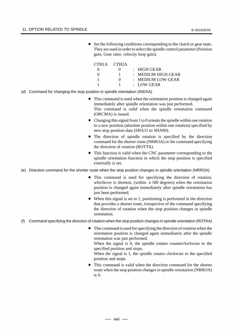
11. OPTION RELATED TO SPINDLE B–65162E/03
440
Set the following conditions corresponding to the clutch or gear state.They are used in order to select the spindle control parameter (Positiongain, Gear ratio, velocity loop gain).
CTH1A CTH2A 0 0 : HIGH GEAR 0 1 : MEDIUM HIGH GEAR 1 0 : MEDIUM LOW GEAR 1 1 : LOW GEAR
(d) Command for changing the stop position in spindle orientation (INDXA)
This command is used when the orientation position is changed againimmediately after spindle orientation was just performed.This command is valid when the spindle orientation command(ORCMA) is issued.
Changing this signal from 1 to 0 orients the spindle within one rotationto a new position (absolute position within one rotation) specified bynew stop position data (SHA11 to SHA00).
The direction of spindle rotation is specified by the directioncommand for the shorter route (NRROA) or the command specifyingthe direction of rotation (ROTTA).
This function is valid when the CNC parameter corresponding to thespindle orientation function in which the stop position is specifiedexternally is set.
(e) Direction command for the shorter route when the stop position changes in spindle orientation (NRROA)
This command is used for specifying the direction of rotation,whichever is shortest, (within 180 degrees) when the orientationposition is changed again immediately after spindle orientation hasjust been performed.
When this signal is set to 1, positioning is performed in the directionthat provides a shorter route, irrespective of the command specifyingthe direction of rotation when the stop position changes in spindleorientation.
(f) Command specifying the direction of rotation when the stop position changes in spindle orientation (ROTAA)
This command is used for specifying the direction of rotation when theorientation position is changed again immediately after the spindleorientation was just performed.When the signal is 0, the spindle rotates counterclockwise to thespecified position and stops.When the signal is 1, the spindle rotates clockwise to the specifiedposition and stops.
This command is valid when the direction command for the shorterroute when the stop position changes in spindle orientation (NRROA)is 0.
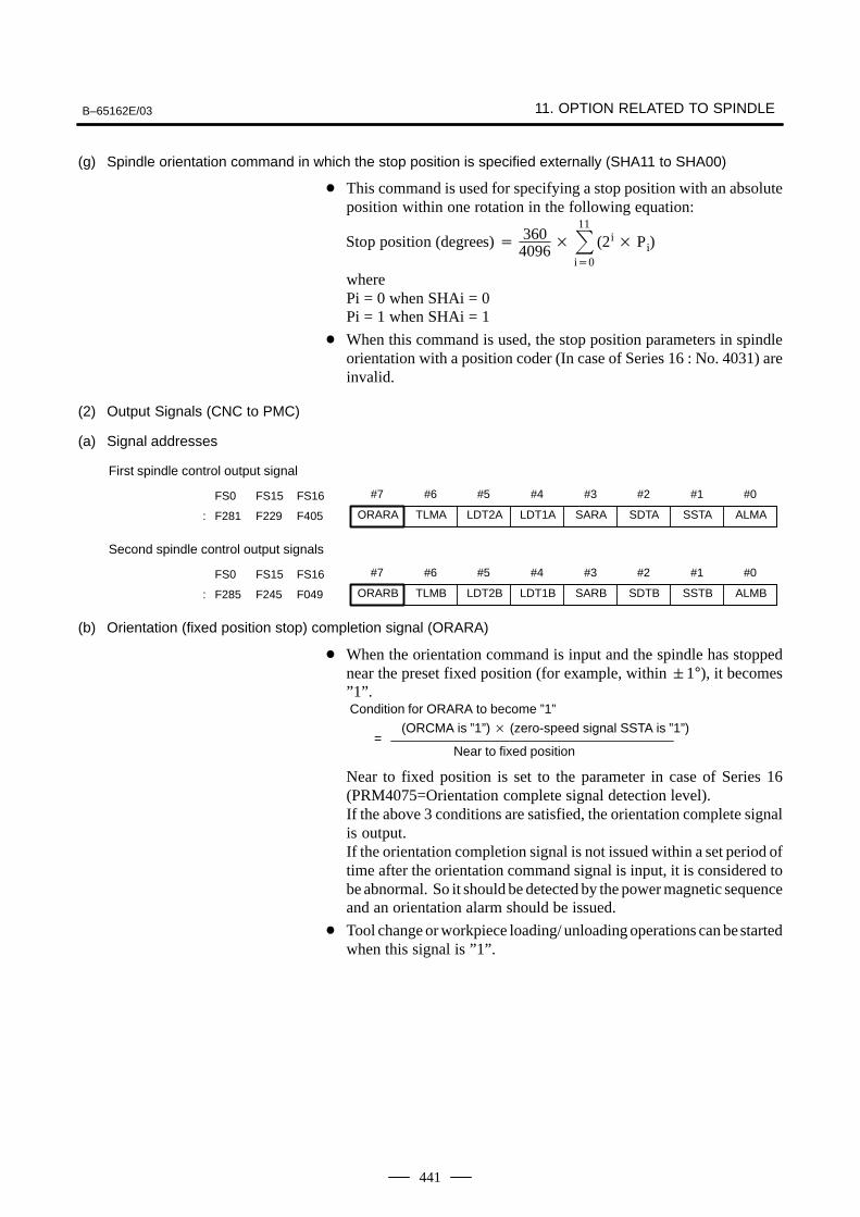
B–65162E/03 11. OPTION RELATED TO SPINDLE
441
(g) Spindle orientation command in which the stop position is specified externally (SHA11 to SHA00)
This command is used for specifying a stop position with an absoluteposition within one rotation in the following equation:
Stop position (degrees) 3604096
11
i0
(2i Pi)
wherePi = 0 when SHAi = 0Pi = 1 when SHAi = 1
When this command is used, the stop position parameters in spindleorientation with a position coder (In case of Series 16 : No. 4031) areinvalid.
(2) Output Signals (CNC to PMC)
(a) Signal addresses
#7 #6 #5 #4 #3 #2 #1 #0FS0 FS15 FS16
ORARA TLMA LDT2A LDT1A SARA SDTA SSTA ALMA: F281 F229 F405
First spindle control output signal
#7 #6 #5 #4 #3 #2 #1 #0FS0 FS15 FS16
ORARB TLMB LDT2B LDT1B SARB SDTB SSTB ALMB: F285 F245 F049
Second spindle control output signals
(b) Orientation (fixed position stop) completion signal (ORARA)
When the orientation command is input and the spindle has stoppednear the preset fixed position (for example, within 1°), it becomes”1”.Condition for ORARA to become ”1”
(ORCMA is ”1”) (zero-speed signal SSTA is ”1”)=
Near to fixed position
Near to fixed position is set to the parameter in case of Series 16(PRM4075=Orientation complete signal detection level).If the above 3 conditions are satisfied, the orientation complete signalis output.If the orientation completion signal is not issued within a set period oftime after the orientation command signal is input, it is considered tobe abnormal. So it should be detected by the power magnetic sequenceand an orientation alarm should be issued.
Tool change or workpiece loading/ unloading operations can be startedwhen this signal is ”1”.
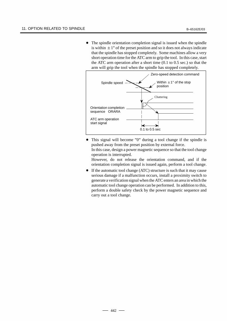
11. OPTION RELATED TO SPINDLE B–65162E/03
442
The spindle orientation completion signal is issued when the spindleis within 1° of the preset position and so it does not always indicatethat the spindle has stopped completely. Some machines allow a veryshort operation time for the ATC arm to grip the tool. In this case, startthe ATC arm operation after a short time (0.1 to 0.5 sec.) so that thearm will grip the tool when the spindle has stopped completely.
0.1 to 0.5 sec
Chattering
Spindle speed
Orientation completionsequence ORARA
ATC arm operationstart signal
Zero-speed detection command
Within 1° of the stopposition
This signal will become ”0” during a tool change if the spindle ispushed away from the preset position by external force.In this case, design a power magnetic sequence so that the tool changeoperation is interrupted.However, do not release the orientation command, and if theorientation completion signal is issued again, perform a tool change.
If the automatic tool change (ATC) structure is such that it may causeserious damage if a malfunction occurs, install a proximity switch togenerate a verification signal when the ATC enters an area in which theautomatic tool change operation can be performed. In addition to this,perform a double safety check by the power magnetic sequence andcarry out a tool change.
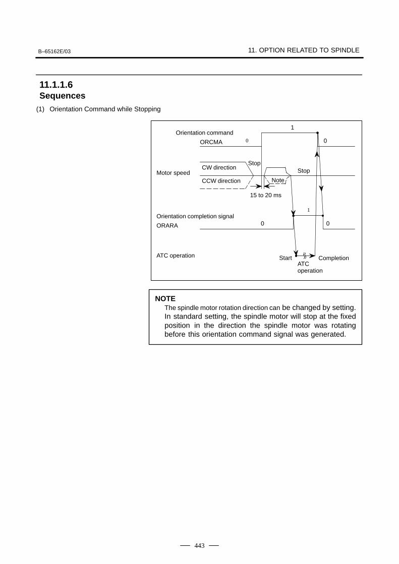
B–65162E/03 11. OPTION RELATED TO SPINDLE
443
(1) Orientation Command while Stopping
CompletionATCoperation
Stop
0
Start
0
1
0
Note
Orientation command
ORCMA
CCW directionMotor speed
CW direction
Orientation completion signal
ORARA
ATC operation
Stop
15 to 20 ms
1
0
NOTEThe spindle motor rotation direction can be changed by setting.In standard setting, the spindle motor will stop at the fixedposition in the direction the spindle motor was rotatingbefore this orientation command signal was generated.
11.1.1.6Sequences
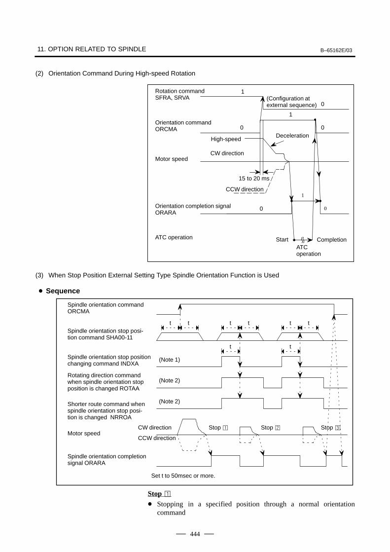
11. OPTION RELATED TO SPINDLE B–65162E/03
444
(2) Orientation Command During High-speed Rotation
CompletionATCoperation
Deceleration
15 to 20 ms
CCW direction
0(Configuration atexternal sequence)
1
0
1
0
1
0
0
Start
High-speed
Rotation commandSFRA, SRVA
Orientation commandORCMA
ATC operation
Motor speed
Orientation completion signalORARA
CW direction
(3) When Stop Position External Setting Type Spindle Orientation Function is Used
Stop Stop Stop CW direction
(Note 1)
t t
t t
(Note 2)
t t
(Note 2)
t t
Spindle orientation command ORCMA
Spindle orientation stop posi-tion command SHA00-11
Spindle orientation stop positionchanging command INDXA
Rotating direction commandwhen spindle orientation stopposition is changed ROTAA
Shorter route command whenspindle orientation stop posi-tion is changed NRROA
CCW direction
Spindle orientation completionsignal ORARA
Set t to 50msec or more.
Motor speed
Stop Stopping in a specified position through a normal orientation
command
Sequence
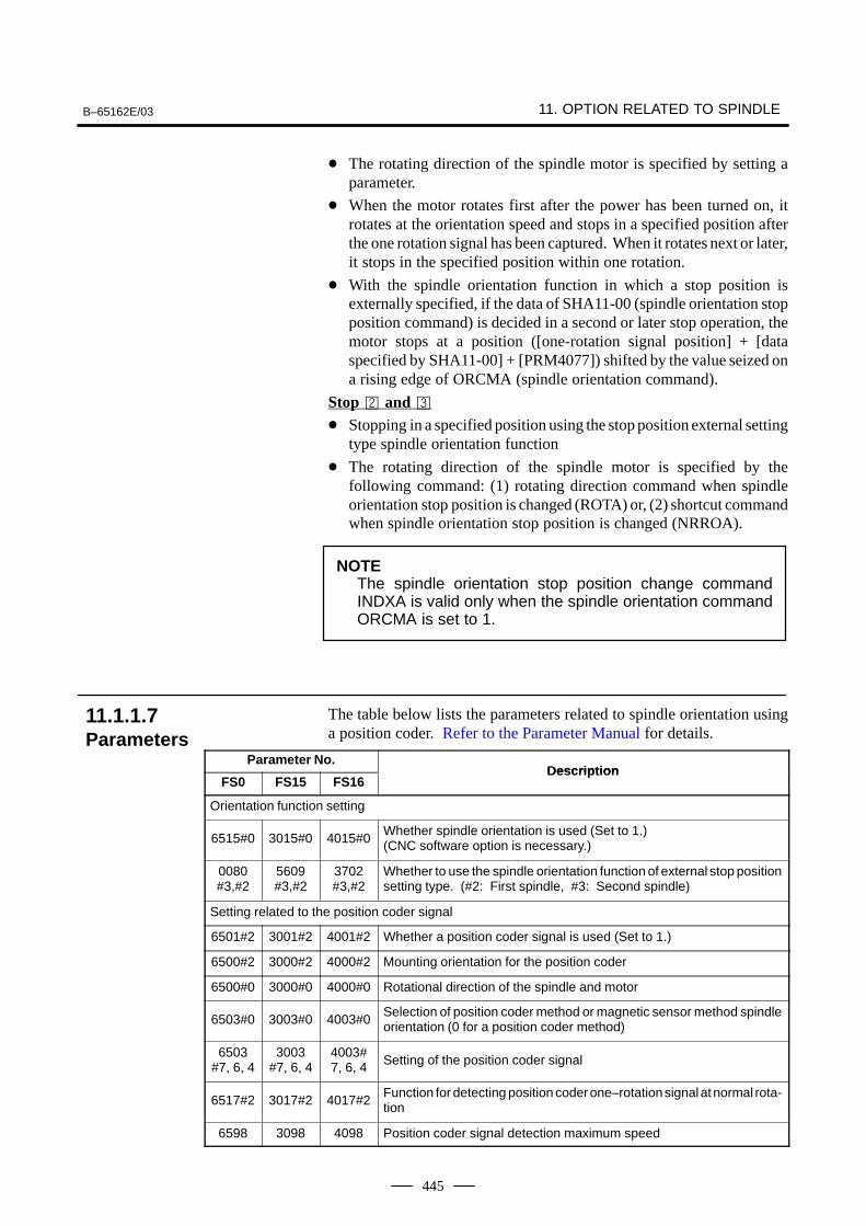
B–65162E/03 11. OPTION RELATED TO SPINDLE
445
The rotating direction of the spindle motor is specified by setting aparameter.
When the motor rotates first after the power has been turned on, itrotates at the orientation speed and stops in a specified position afterthe one rotation signal has been captured. When it rotates next or later,it stops in the specified position within one rotation.
With the spindle orientation function in which a stop position isexternally specified, if the data of SHA11-00 (spindle orientation stopposition command) is decided in a second or later stop operation, themotor stops at a position ([one-rotation signal position] + [dataspecified by SHA11-00] + [PRM4077]) shifted by the value seized ona rising edge of ORCMA (spindle orientation command).
Stop and Stopping in a specified position using the stop position external setting
type spindle orientation function
The rotating direction of the spindle motor is specified by thefollowing command: (1) rotating direction command when spindleorientation stop position is changed (ROTA) or, (2) shortcut commandwhen spindle orientation stop position is changed (NRROA).
NOTEThe spindle orientation stop position change commandINDXA is valid only when the spindle orientation commandORCMA is set to 1.
The table below lists the parameters related to spindle orientation usinga position coder. Refer to the Parameter Manual for details.
Parameter No.Description
FS0 FS15 FS16Description
Orientation function setting
6515#0 3015#0 4015#0Whether spindle orientation is used (Set to 1.)(CNC software option is necessary.)
0080#3,#2
5609#3,#2
3702#3,#2
Whether to use the spindle orientation function of external stop positionsetting type. (#2: First spindle, #3: Second spindle)
Setting related to the position coder signal
6501#2 3001#2 4001#2 Whether a position coder signal is used (Set to 1.)
6500#2 3000#2 4000#2 Mounting orientation for the position coder
6500#0 3000#0 4000#0 Rotational direction of the spindle and motor
6503#0 3003#0 4003#0Selection of position coder method or magnetic sensor method spindleorientation (0 for a position coder method)
6503#7, 6, 4
3003#7, 6, 4
4003#7, 6, 4 Setting of the position coder signal
6517#2 3017#2 4017#2Function for detecting position coder one–rotation signal at normal rota-tion
6598 3098 4098 Position coder signal detection maximum speed
11.1.1.7Parameters
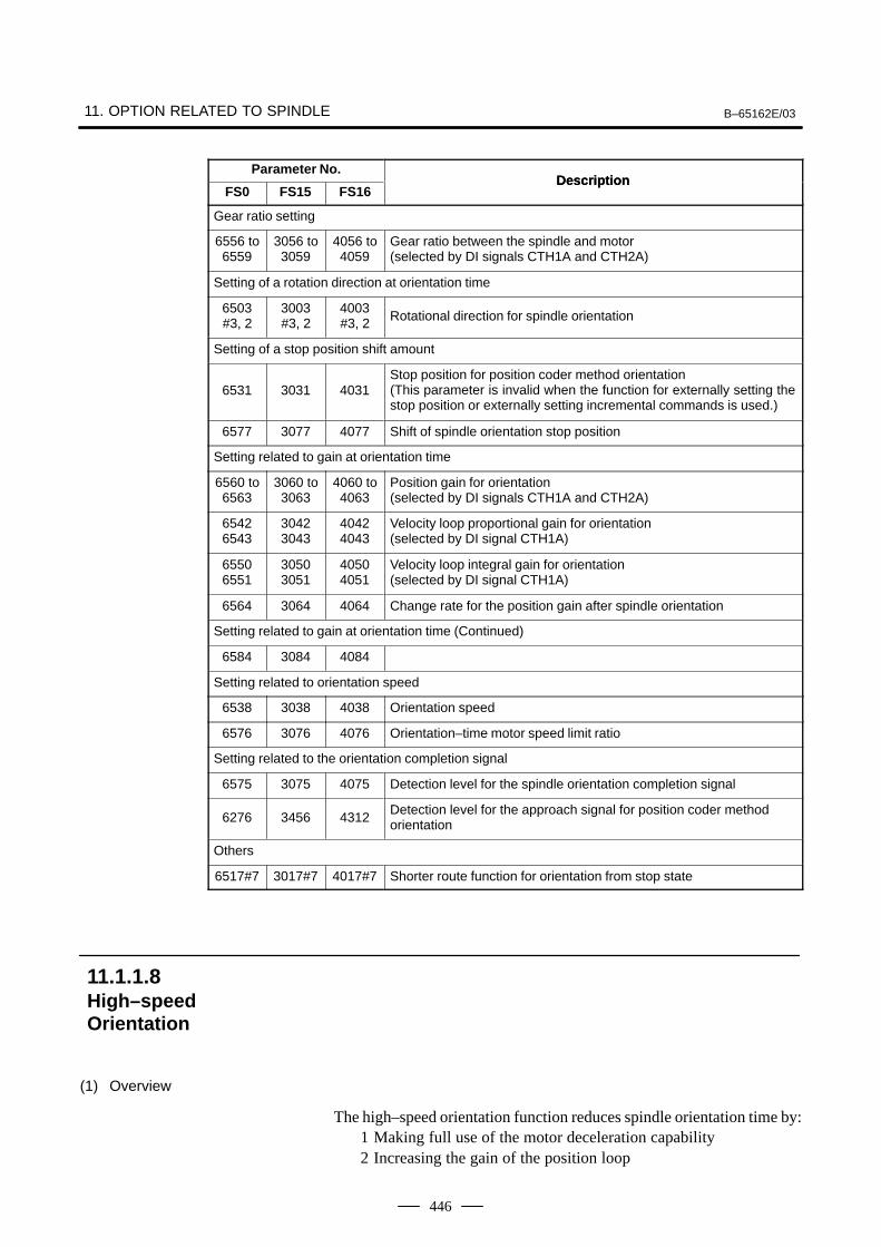
11. OPTION RELATED TO SPINDLE B–65162E/03
446
Parameter No.Description
FS0Description
FS16FS15
Gear ratio setting
6556 to6559
3056 to3059
4056 to4059
Gear ratio between the spindle and motor(selected by DI signals CTH1A and CTH2A)
Setting of a rotation direction at orientation time
6503#3, 2
3003#3, 2
4003#3, 2 Rotational direction for spindle orientation
Setting of a stop position shift amount
6531 3031 4031Stop position for position coder method orientation(This parameter is invalid when the function for externally setting thestop position or externally setting incremental commands is used.)
6577 3077 4077 Shift of spindle orientation stop position
Setting related to gain at orientation time
6560 to6563
3060 to3063
4060 to4063
Position gain for orientation(selected by DI signals CTH1A and CTH2A)
65426543
30423043
40424043
Velocity loop proportional gain for orientation(selected by DI signal CTH1A)
65506551
30503051
40504051
Velocity loop integral gain for orientation(selected by DI signal CTH1A)
6564 3064 4064 Change rate for the position gain after spindle orientation
Setting related to gain at orientation time (Continued)
6584 3084 4084
Setting related to orientation speed
6538 3038 4038 Orientation speed
6576 3076 4076 Orientation–time motor speed limit ratio
Setting related to the orientation completion signal
6575 3075 4075 Detection level for the spindle orientation completion signal
6276 3456 4312Detection level for the approach signal for position coder method orientation
Others
6517#7 3017#7 4017#7 Shorter route function for orientation from stop state
(1) Overview
The high–speed orientation function reduces spindle orientation time by:1 Making full use of the motor deceleration capability2 Increasing the gain of the position loop
11.1.1.8High–speedOrientation
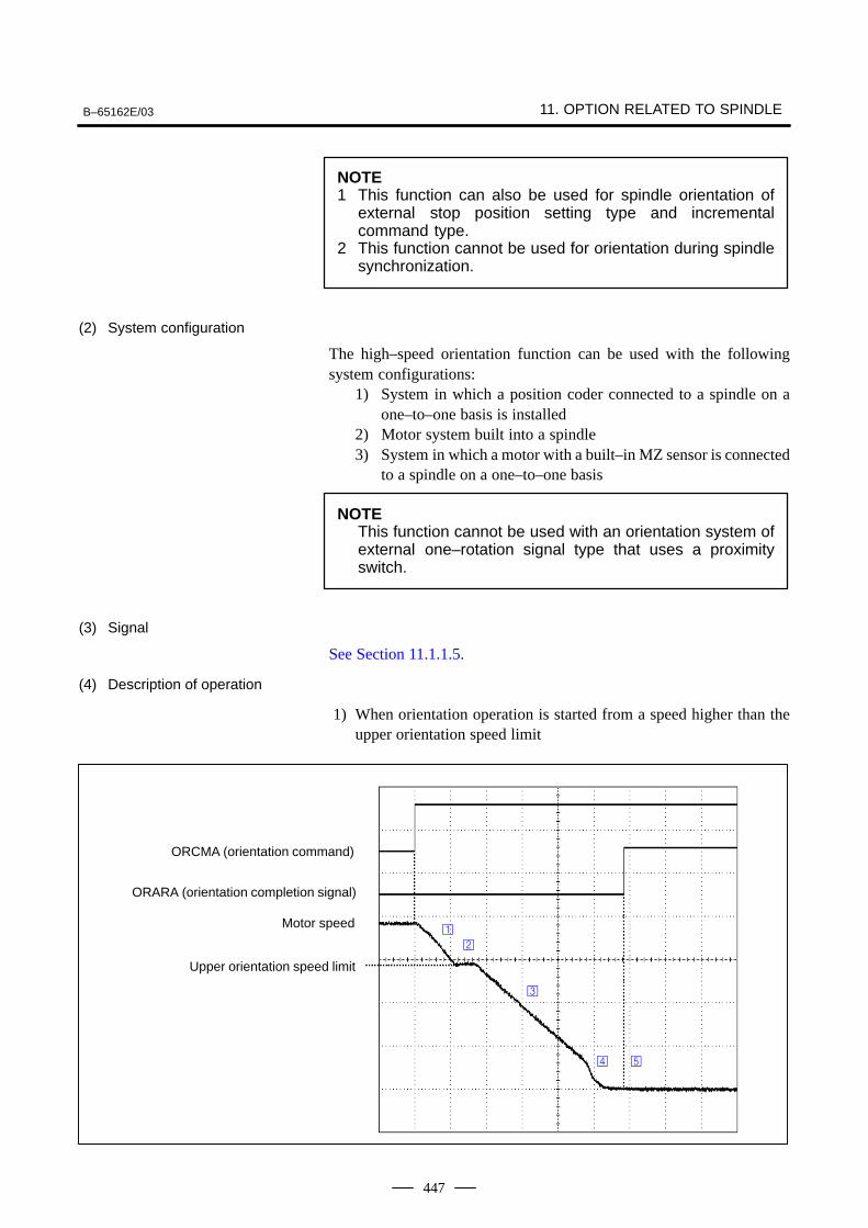
B–65162E/03 11. OPTION RELATED TO SPINDLE
447
NOTE1 This function can also be used for spindle orientation of
external stop position setting type and incrementalcommand type.
2 This function cannot be used for orientation during spindlesynchronization.
(2) System configuration
The high–speed orientation function can be used with the followingsystem configurations:
1) System in which a position coder connected to a spindle on aone–to–one basis is installed
2) Motor system built into a spindle3) System in which a motor with a built–in MZ sensor is connected
to a spindle on a one–to–one basis
NOTEThis function cannot be used with an orientation system ofexternal one–rotation signal type that uses a proximityswitch.
(3) Signal
See Section 11.1.1.5.
(4) Description of operation
1) When orientation operation is started from a speed higher than theupper orientation speed limit
ORCMA (orientation command)
ORARA (orientation completion signal)
Motor speed
Upper orientation speed limit
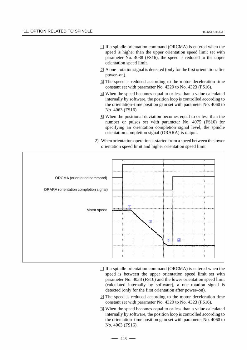
11. OPTION RELATED TO SPINDLE B–65162E/03
448
If a spindle orientation command (ORCMA) is entered when thespeed is higher than the upper orientation speed limit set withparameter No. 4038 (FS16), the speed is reduced to the upperorientation speed limit.
A one–rotation signal is detected (only for the first orientation afterpower–on).
The speed is reduced according to the motor deceleration timeconstant set with parameter No. 4320 to No. 4323 (FS16).
When the speed becomes equal to or less than a value calculatedinternally by software, the position loop is controlled according tothe orientation–time position gain set with parameter No. 4060 toNo. 4063 (FS16).
When the positional deviation becomes equal to or less than thenumber or pulses set with parameter No. 4075 (FS16) forspecifying an orientation completion signal level, the spindleorientation completion signal (ORARA) is output.
2) When orientation operation is started from a speed between the lowerorientation speed limit and higher orientation speed limit
ORCMA (orientation command)
ORARA (orientation completion signal)
Motor speed
If a spindle orientation command (ORCMA) is entered when thespeed is between the upper orientation speed limit set withparameter No. 4038 (FS16) and the lower orientation speed limit(calculated internally by software), a one–rotation signal isdetected (only for the first orientation after power–on).
The speed is reduced according to the motor deceleration timeconstant set with parameter No. 4320 to No. 4323 (FS16).
When the speed becomes equal to or less than a value calculatedinternally by software, the position loop is controlled according tothe orientation–time position gain set with parameter No. 4060 toNo. 4063 (FS16).
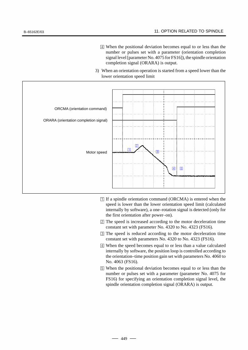
B–65162E/03 11. OPTION RELATED TO SPINDLE
449
When the positional deviation becomes equal to or less than thenumber or pulses set with a parameter (orientation completionsignal level [parameter No. 4075 for FS16]), the spindle orientationcompletion signal (ORARA) is output.
3) When an orientation operation is started from a speed lower than thelower orientation speed limit
ORCMA (orientation command)
ORARA (orientation completion signal)
Motor speed
If a spindle orientation command (ORCMA) is entered when thespeed is lower than the lower orientation speed limit (calculatedinternally by software), a one–rotation signal is detected (only forthe first orientation after power–on).
The speed is increased according to the motor deceleration timeconstant set with parameter No. 4320 to No. 4323 (FS16).
The speed is reduced according to the motor deceleration timeconstant set with parameters No. 4320 to No. 4323 (FS16).
When the speed becomes equal to or less than a value calculatedinternally by software, the position loop is controlled according tothe orientation–time position gain set with parameters No. 4060 toNo. 4063 (FS16).
When the positional deviation becomes equal to or less than thenumber or pulses set with a parameter (parameter No. 4075 forFS16) for specifying an orientation completion signal level, thespindle orientation completion signal (ORARA) is output.
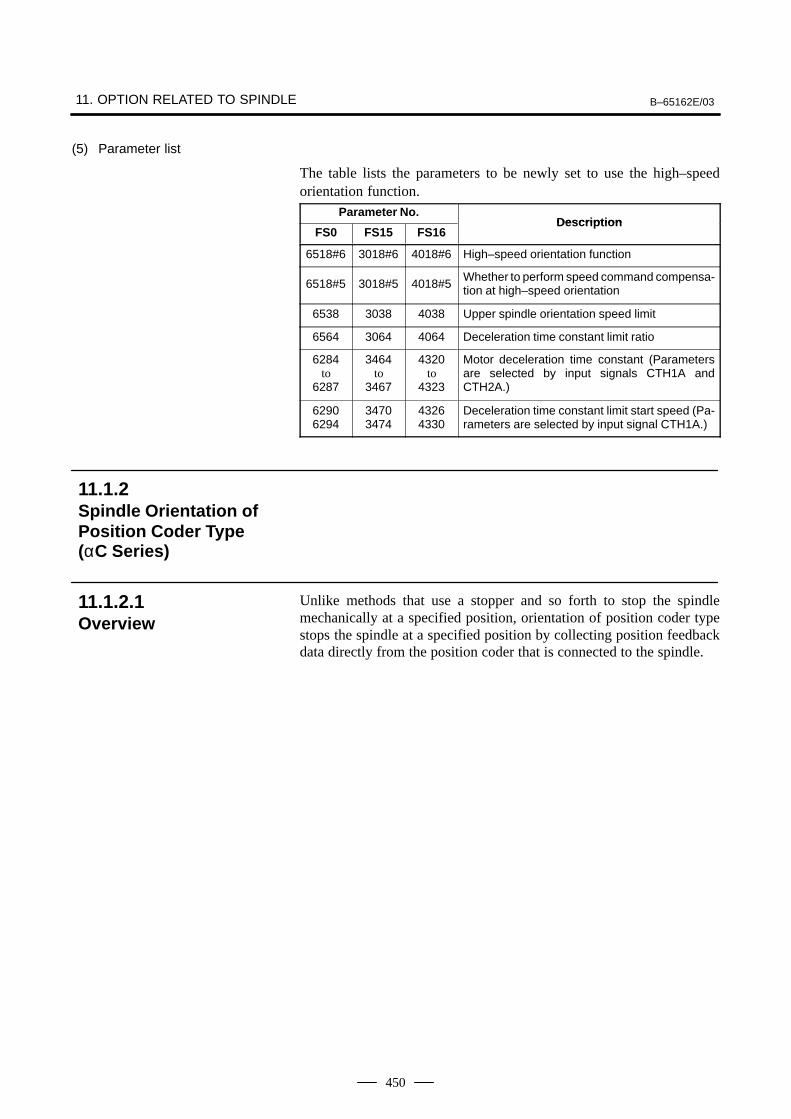
11. OPTION RELATED TO SPINDLE B–65162E/03
450
(5) Parameter list
The table lists the parameters to be newly set to use the high–speedorientation function.
Parameter No.Description
FS0 FS15 FS16Description
6518#6 3018#6 4018#6 High–speed orientation function
6518#5 3018#5 4018#5Whether to perform speed command compensa-tion at high–speed orientation
6538 3038 4038 Upper spindle orientation speed limit
6564 3064 4064 Deceleration time constant limit ratio
6284to
6287
3464to
3467
4320to
4323
Motor deceleration time constant (Parametersare selected by input signals CTH1A andCTH2A.)
62906294
34703474
43264330
Deceleration time constant limit start speed (Pa-rameters are selected by input signal CTH1A.)
Unlike methods that use a stopper and so forth to stop the spindlemechanically at a specified position, orientation of position coder typestops the spindle at a specified position by collecting position feedbackdata directly from the position coder that is connected to the spindle.
11.1.2Spindle Orientation ofPosition Coder Type(αC Series)
11.1.2.1Overview
B–65162E/03 11. OPTION RELATED TO SPINDLE
451
(1) Elimination of the mechanical section
Spindle orientation is enabled simply by connecting a position coder tothe spindle. The mechanical stop mechanism (stopper, pin, and so forth)is not required for orientation.
(2) Reduced orientation time
A spindle motor connected with a spindle is used. So, orientation ispossible at high speed, regardless of the gear shift. This significantlyreduces orientation time.
(3) Simplified power magnetics sequence
The sequence consists of an orientation command, orientationcompletion command, and clutch/gear signal. It does not require anyother signals. This means that sequences for orientation speedspecification and torque limit specification are not required.
(4) Improved reliability
This type of spindle orientation does not depend on mechanicalcomponents, and therefore is not subject to mechanical damage due toexternal shock. Thus, a higher level of reliability is possible.
(5) Workpiece positioning enabled
On a lathe, a workpiece can be positioned for workpieceattachment/detachment direction alignment.
(6) Reduced number of boring steps
Positioning from the same direction as the spindle direction is possibleupon the completion of boring, so that the workpiece is not damaged bythe tool tip. In addition, a tool tip can be attached/detached in onedirection with respect to the workpiece, so that programs can be createdeasily.
11.1.2.2Features
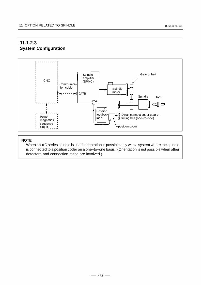
11. OPTION RELATED TO SPINDLE B–65162E/03
452
CNCCommunica-tion cable
Spindleamplifier(SPMC)
JA7B
JY4
Spindlemotor
Gear or belt
Spindle Tool
Powermagneticssequencecircuit
Position feedbackloop
Direct connection, or gear ortiming belt (one–to–one)
αposition coder
NOTEWhen an αC series spindle is used, orientation is possible only with a system where the spindleis connected to a position coder on a one–to–one basis. (Orientation is not possible when otherdetectors and connection ratios are involved.)
11.1.2.3System Configuration
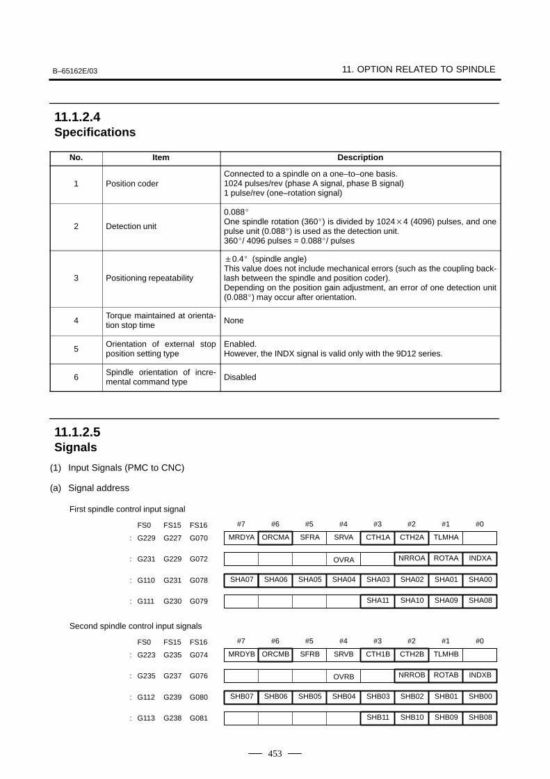
B–65162E/03 11. OPTION RELATED TO SPINDLE
453
No. Item Description
1 Position coderConnected to a spindle on a one–to–one basis.1024 pulses/rev (phase A signal, phase B signal)1 pulse/rev (one–rotation signal)
2 Detection unit
0.088One spindle rotation (360) is divided by 10244 (4096) pulses, and onepulse unit (0.088) is used as the detection unit.360/ 4096 pulses = 0.088/ pulses
3 Positioning repeatability
0.4 (spindle angle)This value does not include mechanical errors (such as the coupling back-lash between the spindle and position coder).Depending on the position gain adjustment, an error of one detection unit(0.088) may occur after orientation.
4Torque maintained at orienta-tion stop time None
5Orientation of external stopposition setting type
Enabled.However, the INDX signal is valid only with the 9D12 series.
6Spindle orientation of incre-mental command type Disabled
(1) Input Signals (PMC to CNC)
(a) Signal address
#7
SHA07
#6
SHA06
#5
SHA05
#4
SHA04
#3
SHA03
#2
SHA02
#1
SHA01
#0
SHA00: G110 G231 G078
FS0 FS15 FS16
SHA11 SHA10 SHA09 SHA08: G111 G230 G079
MRDYA ORCMA SFRA SRVA CTH1A CTH2A TLMHA: G229 G227 G070
OVRA NRROA ROTAA INDXA: G231 G229 G072
First spindle control input signal
#7
SHB07
#6
SHB06
#5
SHB05
#4
SHB04
#3
SHB03
#2
SHB02
#1
SHB01
#0
SHB00: G112 G239 G080
FS0 FS15 FS16
SHB11 SHB10 SHB09 SHB08: G113 G238 G081
MRDYB ORCMB SFRB SRVB CTH1B CTH2B TLMHB: G223 G235 G074
OVRB NRROB ROTAB INDXB: G235 G237 G076
Second spindle control input signals
11.1.2.4Specifications
11.1.2.5Signals
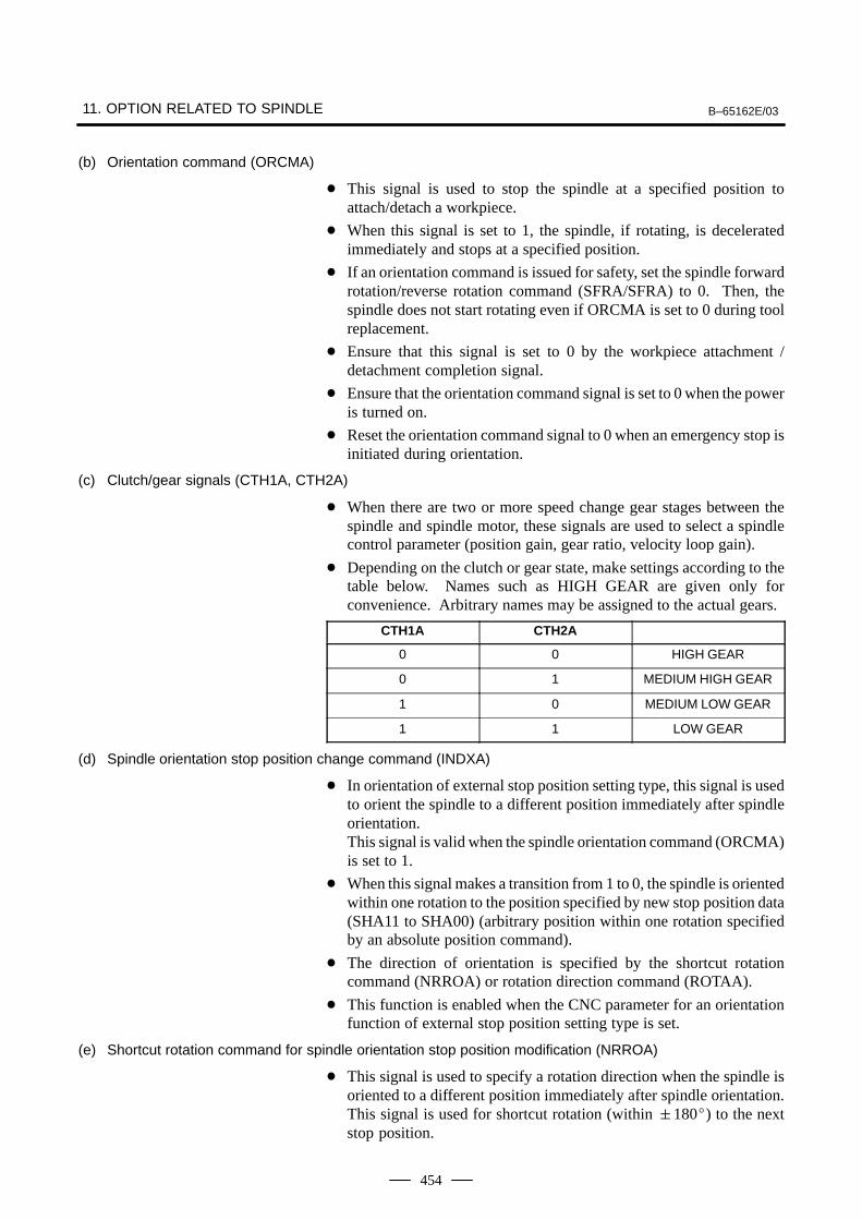
11. OPTION RELATED TO SPINDLE B–65162E/03
454
(b) Orientation command (ORCMA)
This signal is used to stop the spindle at a specified position toattach/detach a workpiece.
When this signal is set to 1, the spindle, if rotating, is deceleratedimmediately and stops at a specified position.
If an orientation command is issued for safety, set the spindle forwardrotation/reverse rotation command (SFRA/SFRA) to 0. Then, thespindle does not start rotating even if ORCMA is set to 0 during toolreplacement.
Ensure that this signal is set to 0 by the workpiece attachment /detachment completion signal.
Ensure that the orientation command signal is set to 0 when the poweris turned on.
Reset the orientation command signal to 0 when an emergency stop isinitiated during orientation.
(c) Clutch/gear signals (CTH1A, CTH2A)
When there are two or more speed change gear stages between thespindle and spindle motor, these signals are used to select a spindlecontrol parameter (position gain, gear ratio, velocity loop gain).
Depending on the clutch or gear state, make settings according to thetable below. Names such as HIGH GEAR are given only forconvenience. Arbitrary names may be assigned to the actual gears.
CTH1A CTH2A
0 0 HIGH GEAR
0 1 MEDIUM HIGH GEAR
1 0 MEDIUM LOW GEAR
1 1 LOW GEAR
(d) Spindle orientation stop position change command (INDXA)
In orientation of external stop position setting type, this signal is usedto orient the spindle to a different position immediately after spindleorientation. This signal is valid when the spindle orientation command (ORCMA)is set to 1.
When this signal makes a transition from 1 to 0, the spindle is orientedwithin one rotation to the position specified by new stop position data(SHA11 to SHA00) (arbitrary position within one rotation specifiedby an absolute position command).
The direction of orientation is specified by the shortcut rotationcommand (NRROA) or rotation direction command (ROTAA).
This function is enabled when the CNC parameter for an orientationfunction of external stop position setting type is set.
(e) Shortcut rotation command for spindle orientation stop position modification (NRROA)
This signal is used to specify a rotation direction when the spindle isoriented to a different position immediately after spindle orientation.This signal is used for shortcut rotation (within 180) to the nextstop position.
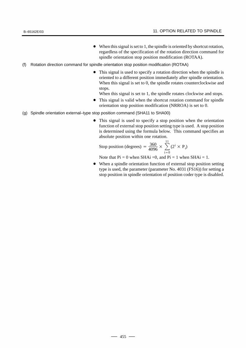
B–65162E/03 11. OPTION RELATED TO SPINDLE
455
When this signal is set to 1, the spindle is oriented by shortcut rotation,regardless of the specification of the rotation direction command forspindle orientation stop position modification (ROTAA).
(f) Rotation direction command for spindle orientation stop position modification (ROTAA)
This signal is used to specify a rotation direction when the spindle isoriented to a different position immediately after spindle orientation.When this signal is set to 0, the spindle rotates counterclockwise andstops.When this signal is set to 1, the spindle rotates clockwise and stops.
This signal is valid when the shortcut rotation command for spindleorientation stop position modification (NRROA) is set to 0.
(g) Spindle orientation external–type stop position command (SHA11 to SHA00)
This signal is used to specify a stop position when the orientationfunction of external stop position setting type is used. A stop positionis determined using the formula below. This command specifies anabsolute position within one rotation.
Stop position (degrees) 3604096
11
i0
(2i Pi)
Note that Pi = 0 when SHAi =0, and Pi = 1 when SHAi = 1.
When a spindle orientation function of external stop position settingtype is used, the parameter (parameter No. 4031 (FS16)) for setting astop position in spindle orientation of position coder type is disabled.
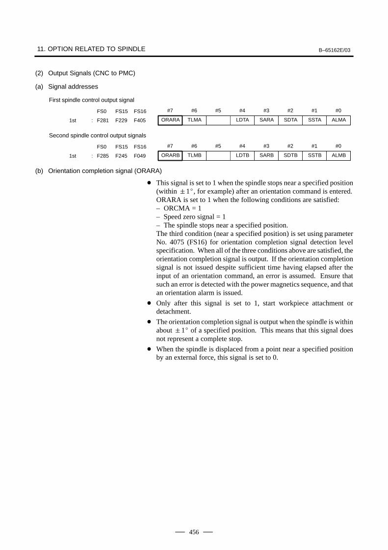
11. OPTION RELATED TO SPINDLE B–65162E/03
456
(2) Output Signals (CNC to PMC)
(a) Signal addresses
#7 #6 #5 #4 #3 #2 #1 #0FS0 FS15 FS16
ORARA TLMA LDTA SARA SDTA SSTA ALMA1st : F281 F229 F405
First spindle control output signal
#7 #6 #5 #4 #3 #2 #1 #0FS0 FS15 FS16
ORARB TLMB LDTB SARB SDTB SSTB ALMB1st : F285 F245 F049
Second spindle control output signals
(b) Orientation completion signal (ORARA)
This signal is set to 1 when the spindle stops near a specified position(within 1, for example) after an orientation command is entered.ORARA is set to 1 when the following conditions are satisfied:– ORCMA = 1– Speed zero signal = 1– The spindle stops near a specified position.The third condition (near a specified position) is set using parameterNo. 4075 (FS16) for orientation completion signal detection levelspecification. When all of the three conditions above are satisfied, theorientation completion signal is output. If the orientation completionsignal is not issued despite sufficient time having elapsed after theinput of an orientation command, an error is assumed. Ensure thatsuch an error is detected with the power magnetics sequence, and thatan orientation alarm is issued.
Only after this signal is set to 1, start workpiece attachment ordetachment.
The orientation completion signal is output when the spindle is withinabout 1 of a specified position. This means that this signal doesnot represent a complete stop.
When the spindle is displaced from a point near a specified positionby an external force, this signal is set to 0.
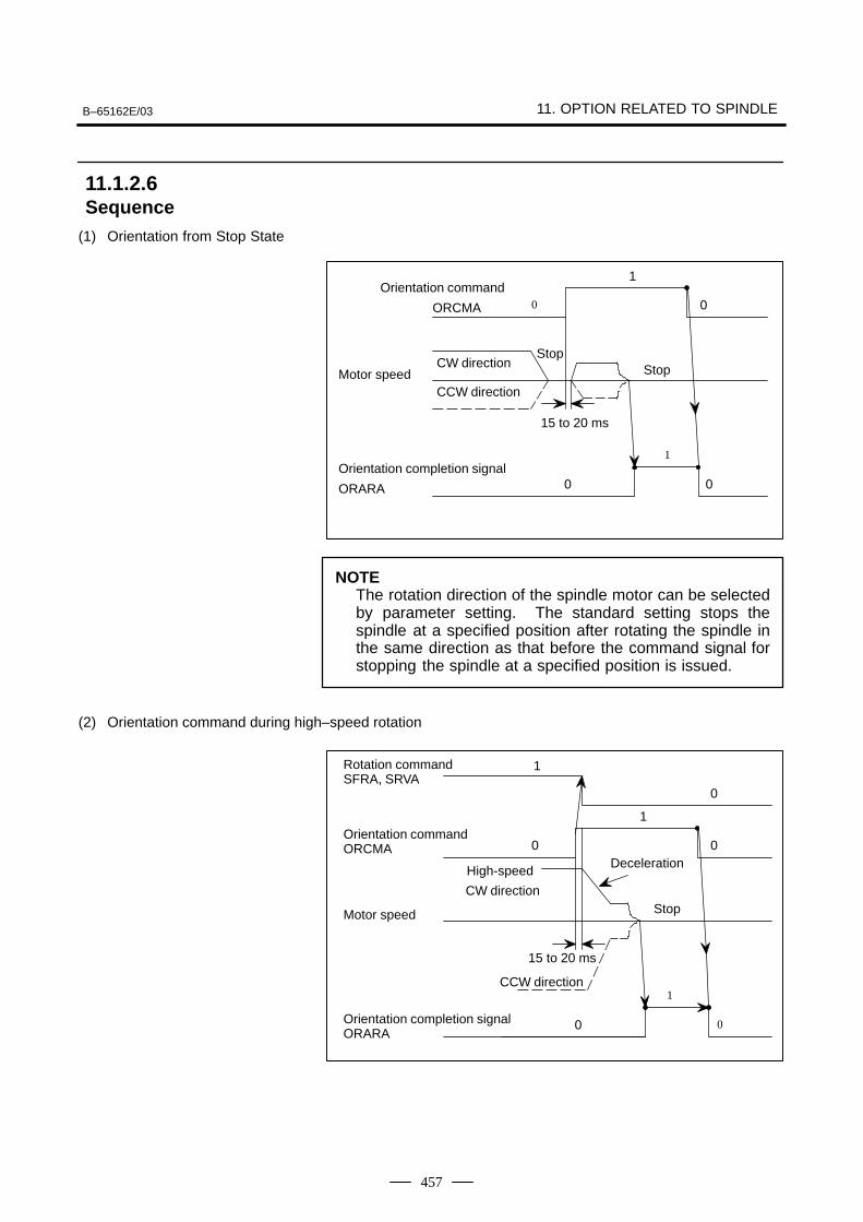
B–65162E/03 11. OPTION RELATED TO SPINDLE
457
(1) Orientation from Stop State
Stop
0
0
1
0Orientation command
ORCMA
CCW directionMotor speed
CW direction
Orientation completion signal
ORARA
Stop
15 to 20 ms
1
0
NOTEThe rotation direction of the spindle motor can be selectedby parameter setting. The standard setting stops thespindle at a specified position after rotating the spindle inthe same direction as that before the command signal forstopping the spindle at a specified position is issued.
(2) Orientation command during high–speed rotation
Deceleration
15 to 20 ms
CCW direction
0
1
0
1
0
1
0
0
High-speed
Rotation commandSFRA, SRVA
Orientation commandORCMA
Motor speed
Orientation completion signalORARA
CW directionStop
11.1.2.6Sequence
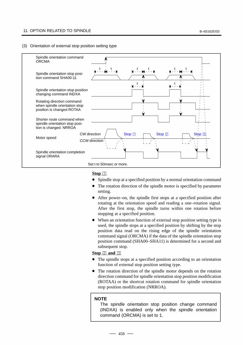
11. OPTION RELATED TO SPINDLE B–65162E/03
458
(3) Orientation of external stop position setting type
Stop Stop Stop CW direction
t t
t t
t t t t
Spindle orientation command ORCMA
Spindle orientation stop posi-tion command SHA00-11
Spindle orientation stop positionchanging command INDXA
Rotating direction commandwhen spindle orientation stopposition is changed ROTAA
Shorter route command whenspindle orientation stop posi-tion is changed NRROA
CCW direction
Spindle orientation completionsignal ORARA
Set t to 50msec or more.
Motor speed
Stop Spindle stop at a specified position by a normal orientation command
The rotation direction of the spindle motor is specified by parametersetting.
After power–on, the spindle first stops at a specified position afterrotating at the orientation speed and reading a one–rotation signal.After the first stop, the spindle turns within one rotation beforestopping at a specified position.
When an orientation function of external stop position setting type isused, the spindle stops at a specified position by shifting by the stopposition data read on the rising edge of the spindle orientationcommand signal (ORCMA) if the data of the spindle orientation stopposition command (SHA00–SHA11) is determined for a second andsubsequent stop.
Stop and The spindle stops at a specified position according to an orientation
function of external stop position setting type.
The rotation direction of the spindle motor depends on the rotationdirection command for spindle orientation stop position modification(ROTAA) or the shortcut rotation command for spindle orientationstop position modification (NRROA).
NOTEThe spindle orientation stop position change command(INDXA) is enabled only when the spindle orientationcommand (ORCMA) is set to 1.
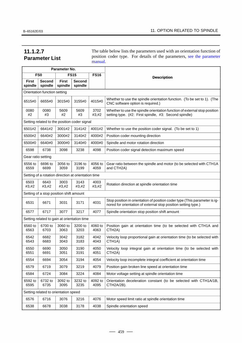
B–65162E/03 11. OPTION RELATED TO SPINDLE
459
The table below lists the parameters used with an orientation function ofposition coder type. For details of the parameters, see the parametermanual.
Parameter No.
FS0 FS15 FS16Description
Firstspindle
Secondspindle
Firstspindle
Secondspindle
Description
Orientation function setting
6515#0 6655#0 3015#0 3155#0 4015#0Whether to use the spindle orientation function. (To be set to 1). (TheCNC software option is required.)
0080#2
0080#3
5609#2
5609#3
3702#3,#2
Whether to use the spindle orientation function of external stop positionsetting type. (#2: First spindle, #3: Second spindle)
Setting related to the position coder signal
6501#2 6641#2 3001#2 3141#2 4001#2 Whether to use the position coder signal. (To be set to 1)
6500#2 6640#2 3000#2 3140#2 4000#2 Position coder mounting direction
6500#0 6640#0 3000#0 3140#0 4000#0 Spindle and motor rotation direction
6598 6738 3098 3238 4098 Position coder signal detection maximum speed
Gear ratio setting
6556 to6559
6696 to6699
3056 to3059
3196 to3199
4056 to4059
Gear ratio between the spindle and motor (to be selected with CTH1Aand CTH2A)
Setting of a rotation direction at orientation time
6503#3,#2
6643#3,#2
3003#3,#2
3143#3,#2
4003#3,#2 Rotation direction at spindle orientation time
Setting of a stop position shift amount
6531 6671 3031 3171 4031Stop position in orientation of position coder type (This parameter is ig-nored for orientation of external stop position setting type.)
6577 6717 3077 3217 4077 Spindle orientation stop position shift amount
Setting related to gain at orientation time
6560 to6563
6700 to6703
3060 to3063
3200 to3203
4060 to4063
Position gain at orientation time (to be selected with CTH1A andCTH2A)
65426543
66826683
30423043
31823183
40424043
Velocity loop proportional gain at orientation time (to be selected withCTH1A)
65506551
66906691
30503051
31903191
40504051
Velocity loop integral gain at orientation time (to be selected withCTH2A)
6554 6694 3054 3194 4054 Velocity loop incomplete integral coefficient at orientation time
6579 6719 3079 3219 4079 Position gain broken line speed at orientation time
6584 6724 3084 3224 4084 Motor voltage setting at spindle orientation time
6592 to6595
6732 to6735
3092 to3095
3232 to3235
4092 to4095
Orientation deceleration constant (to be selected with CTH1A/1B,CTH2A/2B).
Setting related to orientation speed
6576 6716 3076 3216 4076 Motor speed limit ratio at spindle orientation time
6538 6678 3038 3178 4038 Spindle orientation speed
11.1.2.7Parameter List
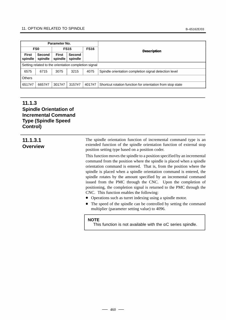
11. OPTION RELATED TO SPINDLE B–65162E/03
460
Parameter No.
DescriptionFS0
DescriptionFS16FS15
Firstspindle
DescriptionSecondspindle
Firstspindle
Secondspindle
Setting related to the orientation completion signal
6575 6715 3075 3215 4075 Spindle orientation completion signal detection level
Others
6517#7 6657#7 3017#7 3157#7 4017#7 Shortcut rotation function for orientation from stop state
The spindle orientation function of incremental command type is anextended function of the spindle orientation function of external stopposition setting type based on a position coder.
This function moves the spindle to a position specified by an incrementalcommand from the position where the spindle is placed when a spindleorientation command is entered. That is, from the position where thespindle is placed when a spindle orientation command is entered, thespindle rotates by the amount specified by an incremental commandissued from the PMC through the CNC. Upon the completion ofpositioning, the completion signal is returned to the PMC through theCNC. This function enables the following: Operations such as turret indexing using a spindle motor.
The speed of the spindle can be controlled by setting the commandmultiplier (parameter setting value) to 4096.
NOTEThis function is not available with the αC series spindle.
11.1.3Spindle Orientation ofIncremental CommandType (Spindle SpeedControl)
11.1.3.1Overview
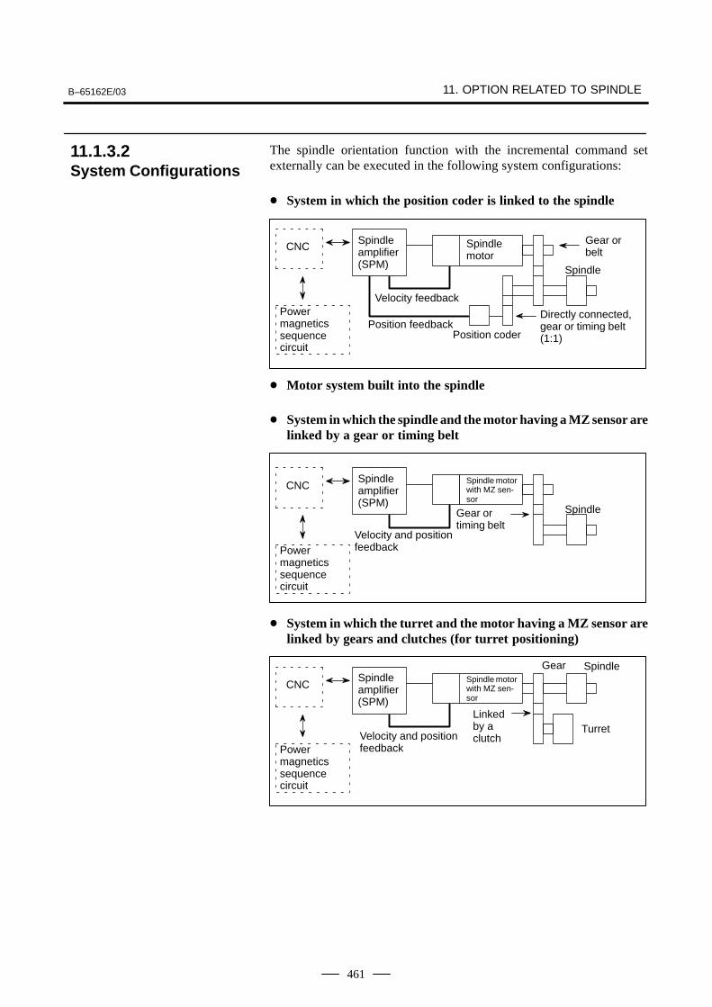
B–65162E/03 11. OPTION RELATED TO SPINDLE
461
The spindle orientation function with the incremental command setexternally can be executed in the following system configurations:
System in which the position coder is linked to the spindle
CNCSpindleamplifier(SPM)
Spindle motor
Directly connected,gear or timing belt(1:1)Position coder
Gear orbelt
Power magneticssequence circuit
Velocity feedback
Position feedback
Spindle
Motor system built into the spindle
System in which the spindle and the motor having a MZ sensor arelinked by a gear or timing belt
Spindle motorwith MZ sen-sor
CNC
Power magneticssequence circuit
Velocity and positionfeedback
SpindleGear ortiming belt
Spindleamplifier(SPM)
System in which the turret and the motor having a MZ sensor arelinked by gears and clutches (for turret positioning)
CNC
Power magneticssequence circuit
Velocity and positionfeedback
SpindleGear
TurretLinkedby aclutch
Spindle motorwith MZ sen-sor
Spindleamplifier(SPM)
11.1.3.2System Configurations
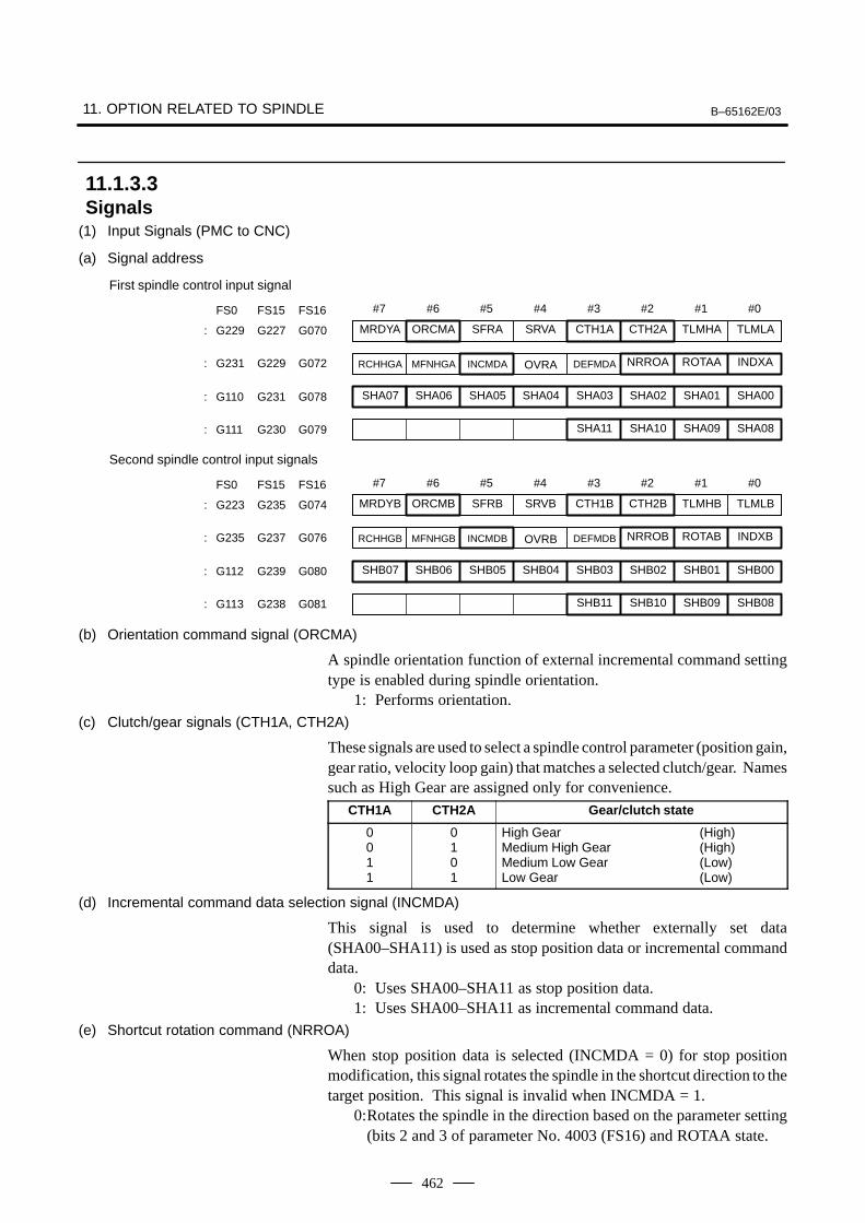
11. OPTION RELATED TO SPINDLE B–65162E/03
462
(1) Input Signals (PMC to CNC)
(a) Signal address
#7
SHA07
#6
SHA06
#5
SHA05
#4
SHA04
#3
SHA03
#2
SHA02
#1
SHA01
#0
SHA00: G110 G231 G078
FS0 FS15 FS16
SHA11 SHA10 SHA09 SHA08: G111 G230 G079
MRDYA ORCMA SFRA SRVA CTH1A CTH2A TLMHA TLMLA: G229 G227 G070
RCHHGA MFNHGA INCMDA OVRA DEFMDA NRROA ROTAA INDXA: G231 G229 G072
First spindle control input signal
#7
SHB07
#6
SHB06
#5
SHB05
#4
SHB04
#3
SHB03
#2
SHB02
#1
SHB01
#0
SHB00: G112 G239 G080
FS0 FS15 FS16
SHB11 SHB10 SHB09 SHB08: G113 G238 G081
MRDYB ORCMB SFRB SRVB CTH1B CTH2B TLMHB TLMLB: G223 G235 G074
RCHHGB MFNHGB INCMDB OVRB DEFMDB NRROB ROTAB INDXB: G235 G237 G076
Second spindle control input signals
(b) Orientation command signal (ORCMA)
A spindle orientation function of external incremental command settingtype is enabled during spindle orientation.
1: Performs orientation.(c) Clutch/gear signals (CTH1A, CTH2A)
These signals are used to select a spindle control parameter (position gain,gear ratio, velocity loop gain) that matches a selected clutch/gear. Namessuch as High Gear are assigned only for convenience.
CTH1A CTH2A Gear/clutch state
0011
0101
High Gear (High)Medium High Gear (High)Medium Low Gear (Low)Low Gear (Low)
(d) Incremental command data selection signal (INCMDA)
This signal is used to determine whether externally set data(SHA00–SHA11) is used as stop position data or incremental commanddata.
0: Uses SHA00–SHA11 as stop position data.1: Uses SHA00–SHA11 as incremental command data.
(e) Shortcut rotation command (NRROA)
When stop position data is selected (INCMDA = 0) for stop positionmodification, this signal rotates the spindle in the shortcut direction to thetarget position. This signal is invalid when INCMDA = 1.
0:Rotates the spindle in the direction based on the parameter setting(bits 2 and 3 of parameter No. 4003 (FS16) and ROTAA state.
11.1.3.3Signals
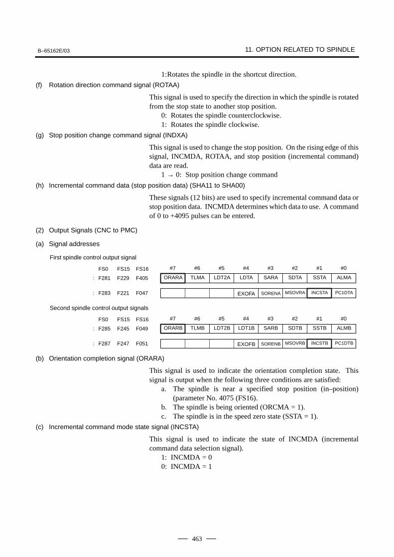
B–65162E/03 11. OPTION RELATED TO SPINDLE
463
1:Rotates the spindle in the shortcut direction.
(f) Rotation direction command signal (ROTAA)
This signal is used to specify the direction in which the spindle is rotatedfrom the stop state to another stop position.
0: Rotates the spindle counterclockwise.1: Rotates the spindle clockwise.
(g) Stop position change command signal (INDXA)
This signal is used to change the stop position. On the rising edge of thissignal, INCMDA, ROTAA, and stop position (incremental command)data are read.
1 → 0: Stop position change command
(h) Incremental command data (stop position data) (SHA11 to SHA00)
These signals (12 bits) are used to specify incremental command data orstop position data. INCMDA determines which data to use. A commandof 0 to +4095 pulses can be entered.
(2) Output Signals (CNC to PMC)
(a) Signal addresses
#7 #6 #5 #4 #3 #2 #1 #0FS0 FS15 FS16
ORARA TLMA LDT2A LDTA SARA SDTA SSTA ALMA: F281 F229 F405
First spindle control output signal
EXOFA SORENA MSOVRA INCSTA PC1DTA: F283 F221 F047
#7 #6 #5 #4 #3 #2 #1 #0FS0 FS15 FS16
ORARB TLMB LDT2B LDT1B SARB SDTB SSTB ALMB: F285 F245 F049
Second spindle control output signals
EXOFB SORENB MSOVRB INCSTB PC1DTB: F287 F247 F051
(b) Orientation completion signal (ORARA)
This signal is used to indicate the orientation completion state. Thissignal is output when the following three conditions are satisfied:
a. The spindle is near a specified stop position (in–position)(parameter No. 4075 (FS16).
b. The spindle is being oriented (ORCMA = 1).c. The spindle is in the speed zero state (SSTA = 1).
(c) Incremental command mode state signal (INCSTA)
This signal is used to indicate the state of INCMDA (incrementalcommand data selection signal).
1: INCMDA = 00: INCMDA = 1
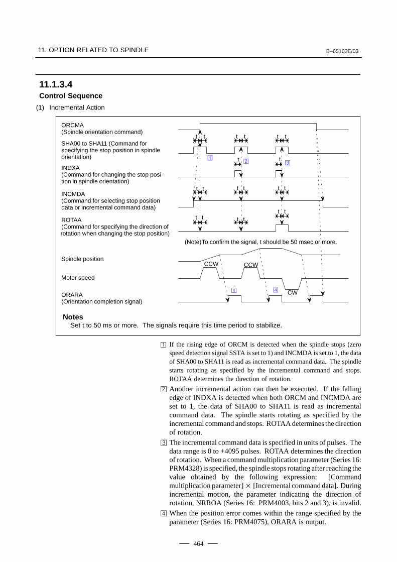
11. OPTION RELATED TO SPINDLE B–65162E/03
464
(1) Incremental Action
ORCMA(Spindle orientation command)
SHA00 to SHA11 (Command forspecifying the stop position in spindleorientation)
INDXA(Command for changing the stop posi-tion in spindle orientation)
INCMDA(Command for selecting stop positiondata or incremental command data)
ROTAA(Command for specifying the direction ofrotation when changing the stop position)
Spindle position
Motor speed
ORARA(Orientation completion signal)
t t t t t t
t t
CCW CCW
t t
t t t t
t tt tt t
CW
NotesSet t to 50 ms or more. The signals require this time period to stabilize.
(Note)To confirm the signal, t should be 50 msec or more.
If the rising edge of ORCM is detected when the spindle stops (zerospeed detection signal SSTA is set to 1) and INCMDA is set to 1, the dataof SHA00 to SHA11 is read as incremental command data. The spindlestarts rotating as specified by the incremental command and stops.ROTAA determines the direction of rotation.
Another incremental action can then be executed. If the fallingedge of INDXA is detected when both ORCM and INCMDA areset to 1, the data of SHA00 to SHA11 is read as incrementalcommand data. The spindle starts rotating as specified by theincremental command and stops. ROTAA determines the directionof rotation.
The incremental command data is specified in units of pulses. Thedata range is 0 to +4095 pulses. ROTAA determines the directionof rotation. When a command multiplication parameter (Series 16:PRM4328) is specified, the spindle stops rotating after reaching thevalue obtained by the following expression: [Commandmultiplication parameter] [Incremental command data]. Duringincremental motion, the parameter indicating the direction ofrotation, NRROA (Series 16: PRM4003, bits 2 and 3), is invalid.
When the position error comes within the range specified by theparameter (Series 16: PRM4075), ORARA is output.
11.1.3.4Control Sequence
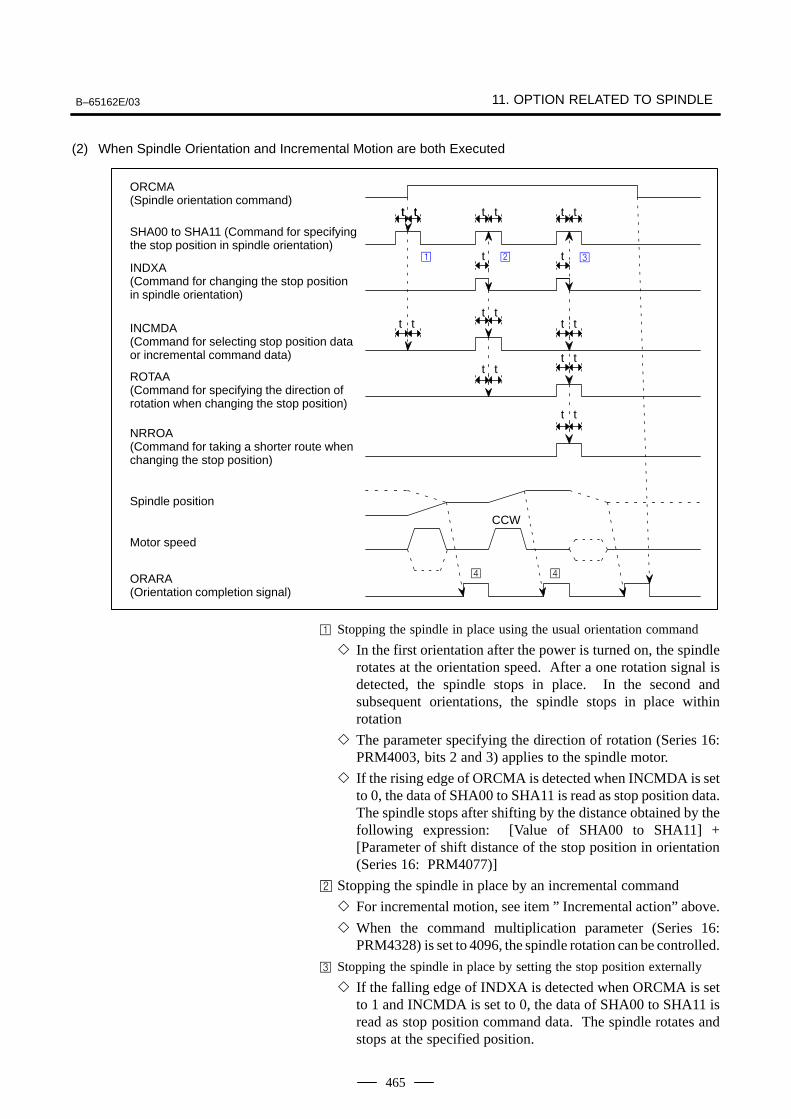
B–65162E/03 11. OPTION RELATED TO SPINDLE
465
(2) When Spindle Orientation and Incremental Motion are both Executed
t
t t
ORCMA(Spindle orientation command)
SHA00 to SHA11 (Command for specifyingthe stop position in spindle orientation)
INDXA(Command for changing the stop positionin spindle orientation)
INCMDA(Command for selecting stop position dataor incremental command data)
ROTAA(Command for specifying the direction ofrotation when changing the stop position)
NRROA(Command for taking a shorter route whenchanging the stop position)
Spindle position
Motor speed
ORARA(Orientation completion signal)
t t t t
CCW
t
t t
t tt t
t t
t tt t
t t
Stopping the spindle in place using the usual orientation command
In the first orientation after the power is turned on, the spindlerotates at the orientation speed. After a one rotation signal isdetected, the spindle stops in place. In the second andsubsequent orientations, the spindle stops in place withinrotation
The parameter specifying the direction of rotation (Series 16:PRM4003, bits 2 and 3) applies to the spindle motor.
If the rising edge of ORCMA is detected when INCMDA is setto 0, the data of SHA00 to SHA11 is read as stop position data.The spindle stops after shifting by the distance obtained by thefollowing expression: [Value of SHA00 to SHA11] +[Parameter of shift distance of the stop position in orientation(Series 16: PRM4077)]
Stopping the spindle in place by an incremental command
For incremental motion, see item ” Incremental action” above.
When the command multiplication parameter (Series 16:PRM4328) is set to 4096, the spindle rotation can be controlled.
Stopping the spindle in place by setting the stop position externally
If the falling edge of INDXA is detected when ORCMA is setto 1 and INCMDA is set to 0, the data of SHA00 to SHA11 isread as stop position command data. The spindle rotates andstops at the specified position.
11. OPTION RELATED TO SPINDLE B–65162E/03
466
NRROA and ROTAA determine the direction of rotation.When NRROA is set to 1, the spindle rotates from the currentstop position to the specified stop position by taking the shorterroute (within 180°). When NRROA is set to 0, ROTAAdetermines the direction of rotation.
The following parameters are added when the function for externallysetting incremental commands is used for position coder method spindleorientation Refer to the Parameter Manual and each CNC manual fordetails.
Parameter No.Description
FS0 FS15 FS16Description
0080#3, 2
5609#3, 2
3702#3, 2
Whether the function for externally setting incremental commands isused (#2: First spindle, #3: Second spindle)
6292 3472 4328Command multiplication for data for externally setting incremental com-mands
This section describes a spindle orientation function. This function isimplemented in a system consisting of an external one–rotation signalswitch (proximity switch) mounted on the spindle, and a spindle motorhaving a built–in sensor and connected to the spindle with an arbitrarygear ratio.
This function is similar to the position coder–based spindle orientationfunction except for the items listed below.1) A fixed orientation must be specified by setting 1 in bit 3 of parameter
No. 4003.2) The detection of a one–rotation signal begins after the orientation
speed is reached.
NOTE1 See Section 11.1.1 for descriptions about anything other
than external one–rotation signal handling (position coder– based spindle orientation).
2 The αC series does not support this function.
11.1.3.5Parameters
11.1.4Spindle Orientation byExternal One RotationSignal
11.1.4.1General
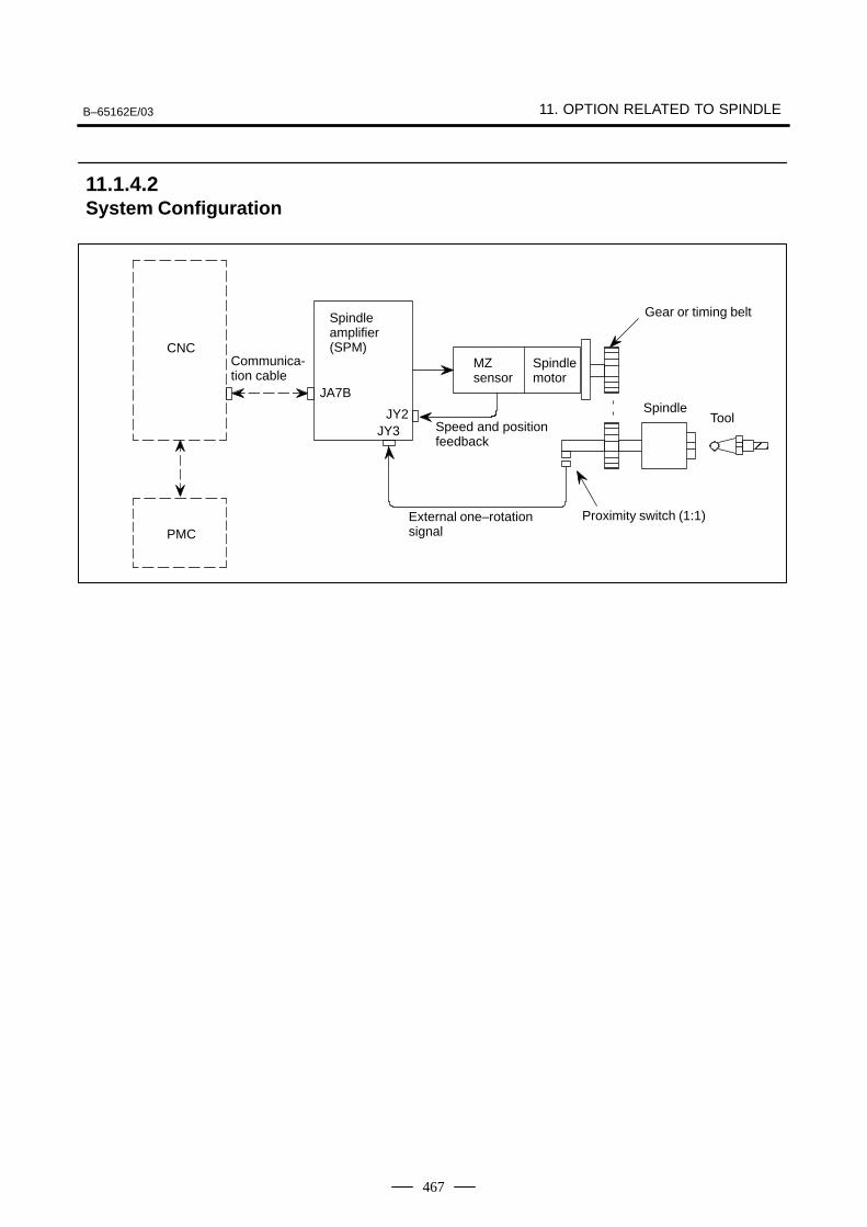
B–65162E/03 11. OPTION RELATED TO SPINDLE
467
Communica-tion cable
PMC
CNC
Spindle amplifier(SPM)
Spindle motor
Gear or timing belt
External one–rotationsignal
Speed and positionfeedback
JY3
SpindleTool
Å
Proximity switch (1:1)
JA7B
JY2
MZ sensor
11.1.4.2System Configuration
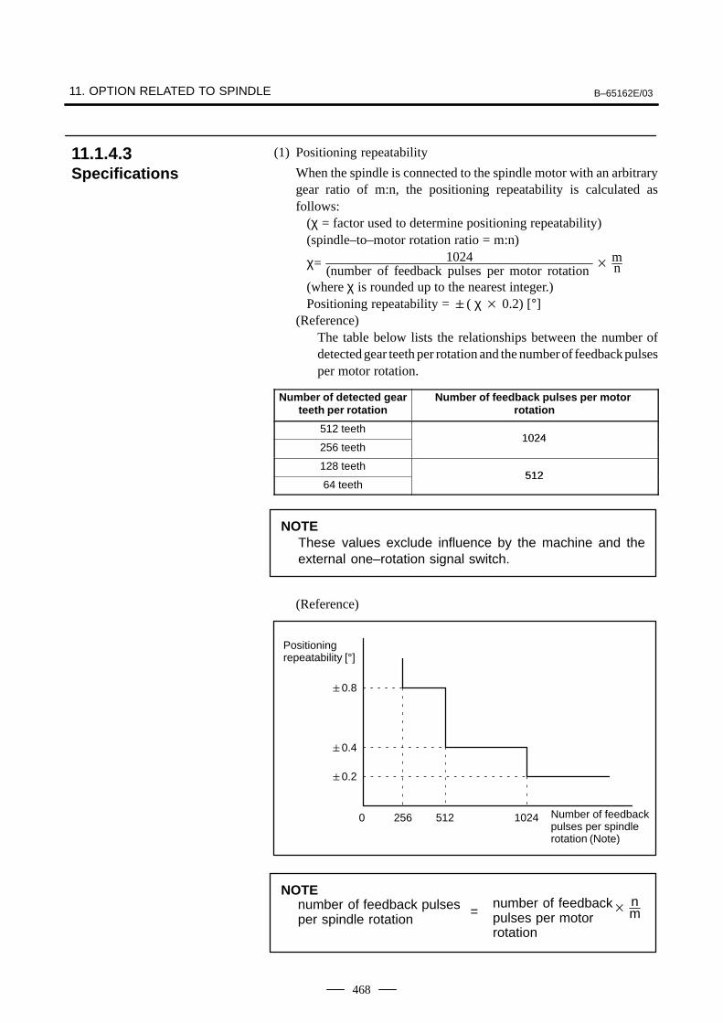
11. OPTION RELATED TO SPINDLE B–65162E/03
468
(1) Positioning repeatability
When the spindle is connected to the spindle motor with an arbitrarygear ratio of m:n, the positioning repeatability is calculated asfollows:
(χ = factor used to determine positioning repeatability)(spindle–to–motor rotation ratio = m:n)
χ= 1024(number of feedback pulses per motor rotation
mn
(where χ is rounded up to the nearest integer.)Positioning repeatability = ( χ 0.2) [°]
(Reference)The table below lists the relationships between the number ofdetected gear teeth per rotation and the number of feedback pulsesper motor rotation.
Number of detected gearteeth per rotation
Number of feedback pulses per motor rotation
512 teeth1024
256 teeth1024
128 teeth512
64 teeth512
NOTEThese values exclude influence by the machine and theexternal one–rotation signal switch.
(Reference)
Positioning repeatability [°]
Number of feedback pulses per spindle rotation (Note)
0.8
0.4
0.2
0 256 512 1024
NOTEnumber of feedback pulses per spindle rotation
=number of feedbackpulses per motorrotation
nm
11.1.4.3Specifications
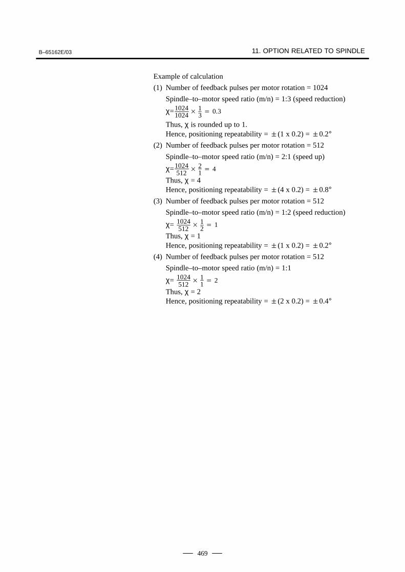
B–65162E/03 11. OPTION RELATED TO SPINDLE
469
Example of calculation
(1) Number of feedback pulses per motor rotation = 1024
Spindle–to–motor speed ratio (m/n) = 1:3 (speed reduction)
χ=10241024
13 0.3
Thus, χ is rounded up to 1.Hence, positioning repeatability = (1 x 0.2) = 0.2°
(2) Number of feedback pulses per motor rotation = 512
Spindle–to–motor speed ratio (m/n) = 2:1 (speed up)
χ=1024512
21 4
Thus, χ = 4Hence, positioning repeatability = (4 x 0.2) = 0.8°
(3) Number of feedback pulses per motor rotation = 512
Spindle–to–motor speed ratio (m/n) = 1:2 (speed reduction)
χ= 1024512
12 1
Thus, χ = 1Hence, positioning repeatability = (1 x 0.2) = 0.2°
(4) Number of feedback pulses per motor rotation = 512
Spindle–to–motor speed ratio (m/n) = 1:1
χ= 1024512
11 2
Thus, χ = 2Hence, positioning repeatability = (2 x 0.2) = 0.4°
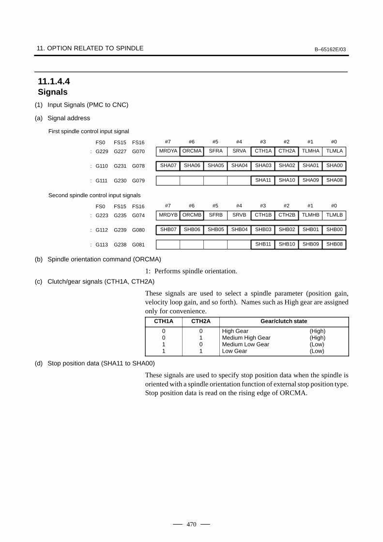
11. OPTION RELATED TO SPINDLE B–65162E/03
470
(1) Input Signals (PMC to CNC)
(a) Signal address
#7
SHA07
#6
SHA06
#5
SHA05
#4
SHA04
#3
SHA03
#2
SHA02
#1
SHA01
#0
SHA00: G110 G231 G078
FS0 FS15 FS16
SHA11 SHA10 SHA09 SHA08: G111 G230 G079
MRDYA ORCMA SFRA SRVA CTH1A CTH2A TLMHA TLMLA: G229 G227 G070
First spindle control input signal
#7
SHB07
#6
SHB06
#5
SHB05
#4
SHB04
#3
SHB03
#2
SHB02
#1
SHB01
#0
SHB00: G112 G239 G080
FS0 FS15 FS16
SHB11 SHB10 SHB09 SHB08: G113 G238 G081
MRDYB ORCMB SFRB SRVB CTH1B CTH2B TLMHB TLMLB: G223 G235 G074
Second spindle control input signals
(b) Spindle orientation command (ORCMA)
1: Performs spindle orientation.
(c) Clutch/gear signals (CTH1A, CTH2A)
These signals are used to select a spindle parameter (position gain,velocity loop gain, and so forth). Names such as High gear are assignedonly for convenience.
CTH1A CTH2A Gear/clutch state
0011
0101
High Gear (High)Medium High Gear (High)Medium Low Gear (Low)Low Gear (Low)
(d) Stop position data (SHA11 to SHA00)
These signals are used to specify stop position data when the spindle isoriented with a spindle orientation function of external stop position type.Stop position data is read on the rising edge of ORCMA.
11.1.4.4Signals
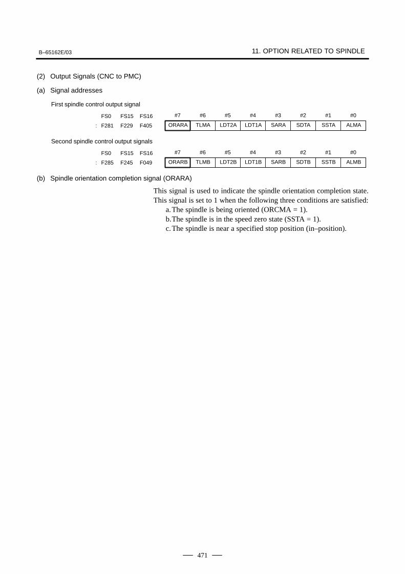
B–65162E/03 11. OPTION RELATED TO SPINDLE
471
(2) Output Signals (CNC to PMC)
(a) Signal addresses
#7 #6 #5 #4 #3 #2 #1 #0FS0 FS15 FS16
ORARA TLMA LDT2A LDT1A SARA SDTA SSTA ALMA: F281 F229 F405
First spindle control output signal
#7 #6 #5 #4 #3 #2 #1 #0FS0 FS15 FS16
ORARB TLMB LDT2B LDT1B SARB SDTB SSTB ALMB: F285 F245 F049
Second spindle control output signals
(b) Spindle orientation completion signal (ORARA)
This signal is used to indicate the spindle orientation completion state.This signal is set to 1 when the following three conditions are satisfied:
a.The spindle is being oriented (ORCMA = 1).b.The spindle is in the speed zero state (SSTA = 1).c.The spindle is near a specified stop position (in–position).
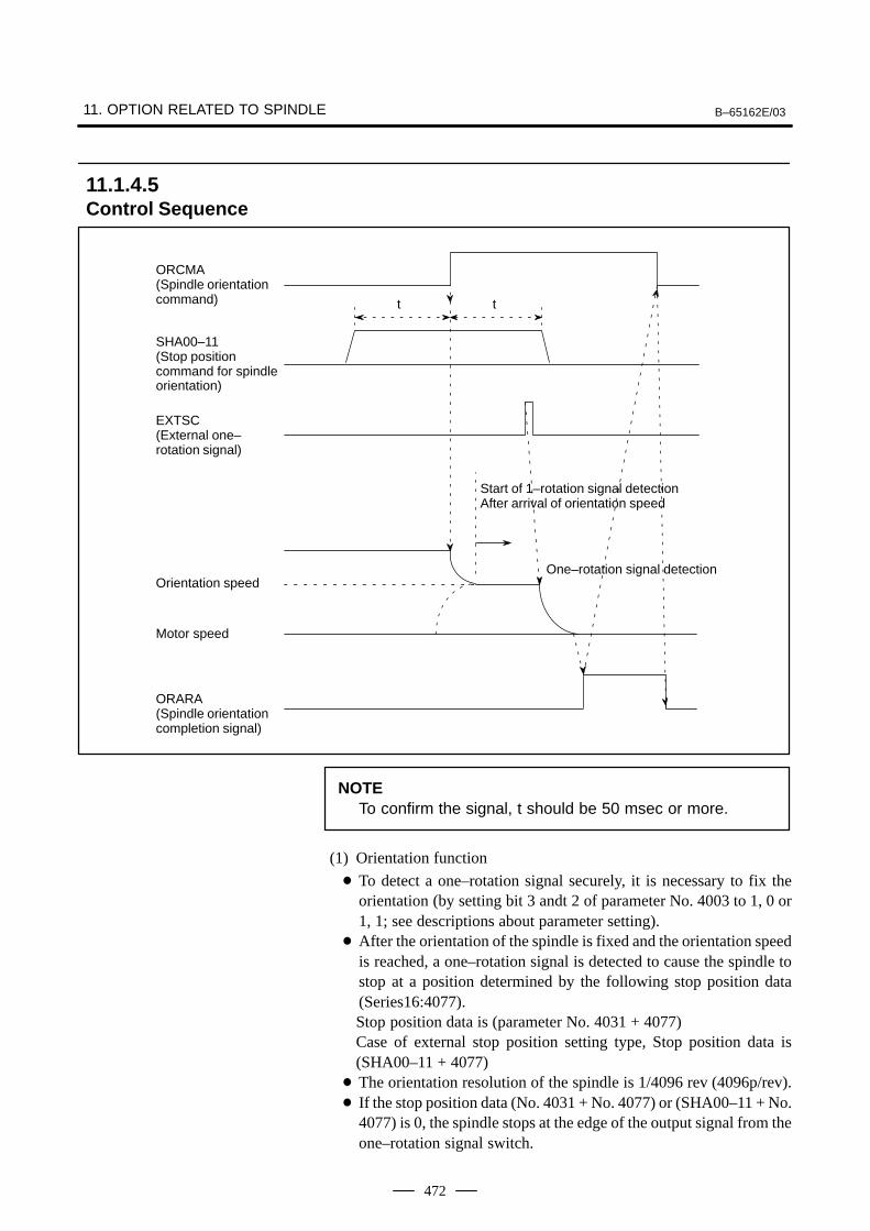
11. OPTION RELATED TO SPINDLE B–65162E/03
472
t t
ORCMA(Spindle orientationcommand)
SHA00–11(Stop position command for spindleorientation)
EXTSC(External one–rotation signal)
Start of 1–rotation signal detectionAfter arrival of orientation speed
One–rotation signal detectionOrientation speed
Motor speed
ORARA(Spindle orientationcompletion signal)
NOTETo confirm the signal, t should be 50 msec or more.
(1) Orientation function
To detect a one–rotation signal securely, it is necessary to fix theorientation (by setting bit 3 andt 2 of parameter No. 4003 to 1, 0 or1, 1; see descriptions about parameter setting).
After the orientation of the spindle is fixed and the orientation speedis reached, a one–rotation signal is detected to cause the spindle tostop at a position determined by the following stop position data(Series16:4077).Stop position data is (parameter No. 4031 + 4077)Case of external stop position setting type, Stop position data is(SHA00–11 + 4077)
The orientation resolution of the spindle is 1/4096 rev (4096p/rev). If the stop position data (No. 4031 + No. 4077) or (SHA00–11 + No.
4077) is 0, the spindle stops at the edge of the output signal from theone–rotation signal switch.
11.1.4.5Control Sequence
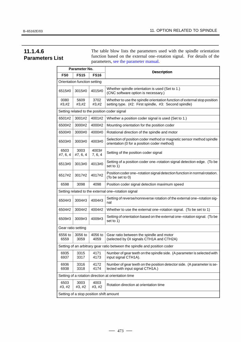
B–65162E/03 11. OPTION RELATED TO SPINDLE
473
The table blow lists the parameters used with the spindle orientationfunction based on the external one–rotation signal. For details of theparameters, see the parameter manual.
Parameter No.Description
FS0 FS15 FS16Description
Orientation function setting
6515#0 3015#0 4015#0Whether spindle orientation is used (Set to 1.)(CNC software option is necessary.)
0080#3,#2
5609#3,#2
3702#3,#2
Whether to use the spindle orientation function of external stop positionsetting type. (#2: First spindle, #3: Second spindle)
Setting related to the position coder signal
6501#2 3001#2 4001#2 Whether a position coder signal is used (Set to 1.)
6500#2 3000#2 4000#2 Mounting orientation for the position coder
6500#0 3000#0 4000#0 Rotational direction of the spindle and motor
6503#0 3003#0 4003#0Selection of position coder method or magnetic sensor method spindleorientation (0 for a position coder method)
6503#7, 6, 4
3003#7, 6, 4
4003#7, 6, 4 Setting of the position coder signal
6513#0 3013#0 4013#0Setting of a position coder one–rotation signal detection edge. (To beset to 1)
6517#2 3017#2 4017#2Position coder one–rotation signal detection function in normal rotation.(To be set to 0)
6598 3098 4098 Position coder signal detection maximum speed
Setting related to the external one–rotation signal
6504#3 3004#3 4004#3Setting of reverse/nonreverse rotation of the external one–rotation sig-nal
6504#2 3004#2 4004#2 Whether to use the external one–rotation signal. (To be set to 1)
6509#3 3009#3 4009#3Setting of orientation based on the external one–rotation signal. (To beset to 1)
Gear ratio setting
6556 to6559
3056 to3059
4056 to4059
Gear ratio between the spindle and motor(selected by DI signals CTH1A and CTH2A)
Setting of an arbitrary gear ratio between the spindle and position coder
69356937
33153317
41714173
Number of gear teeth on the spindle side. (A parameter is selected withinput signal CTH1A).
69366938
33163318
41724174
Number of gear teeth on the position detector side. (A parameter is se-lected with input signal CTH1A.)
Setting of a rotation direction at orientation time
6503#3, #2
3003#3, #2
4003#3, #2 Rotation direction at orientation time
Setting of a stop position shift amount
11.1.4.6Parameters List
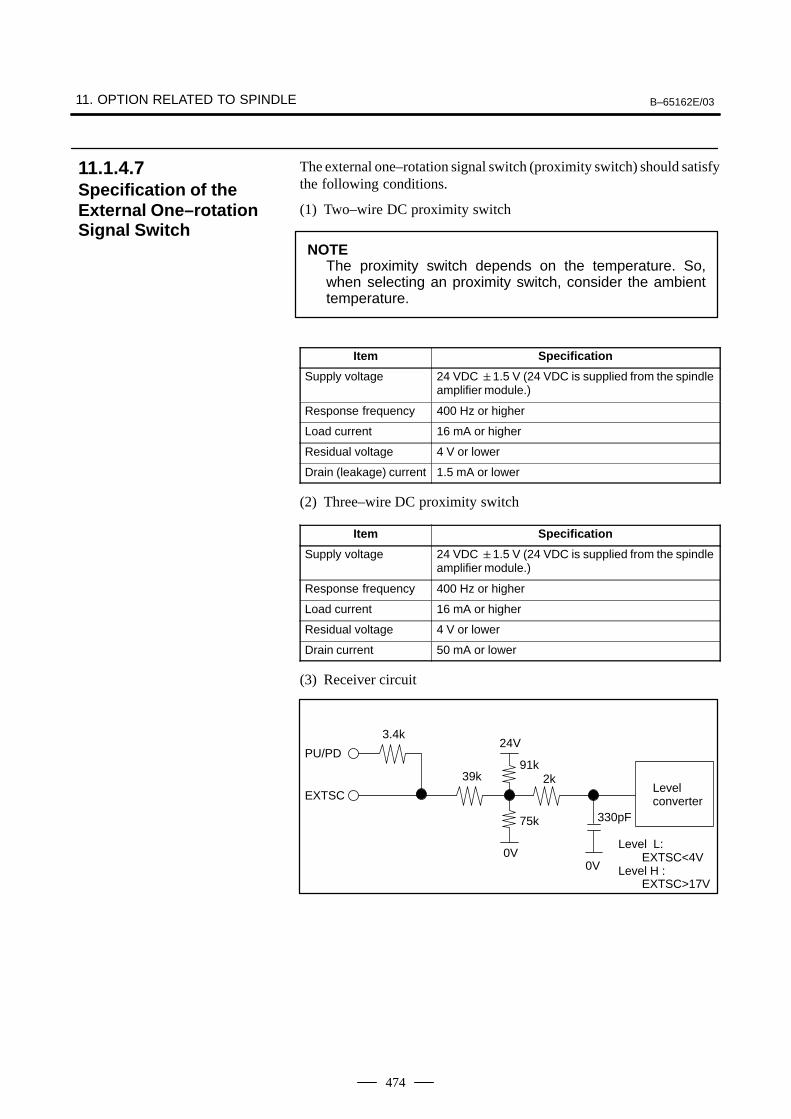
11. OPTION RELATED TO SPINDLE B–65162E/03
474
The external one–rotation signal switch (proximity switch) should satisfythe following conditions.
(1) Two–wire DC proximity switch
NOTEThe proximity switch depends on the temperature. So,when selecting an proximity switch, consider the ambienttemperature.
Item Specification
Supply voltage 24 VDC 1.5 V (24 VDC is supplied from the spindleamplifier module.)
Response frequency 400 Hz or higher
Load current 16 mA or higher
Residual voltage 4 V or lower
Drain (leakage) current 1.5 mA or lower
(2) Three–wire DC proximity switch
Item Specification
Supply voltage 24 VDC 1.5 V (24 VDC is supplied from the spindleamplifier module.)
Response frequency 400 Hz or higher
Load current 16 mA or higher
Residual voltage 4 V or lower
Drain current 50 mA or lower
(3) Receiver circuit
PU/PD
EXTSC
3.4k
39k
24V
91k2k
75k
0V0V
330pF
Level converter
Level L: EXTSC<4V
Level H : EXTSC>17V
11.1.4.7Specification of theExternal One–rotationSignal Switch
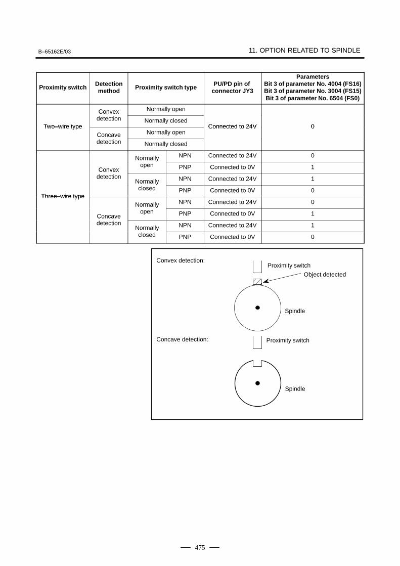
B–65162E/03 11. OPTION RELATED TO SPINDLE
475
Proximity switch Detectionmethod Proximity switch type PU/PD pin of
connector JY3
ParametersBit 3 of parameter No. 4004 (FS16)Bit 3 of parameter No. 3004 (FS15)Bit 3 of parameter No. 6504 (FS0)
Convex Normally open
Two–wire type
Convexdetection Normally closed
Connected to 24V 0Two–wire typeConcave Normally open
Connected to 24V 0Concavedetection Normally closed
Normally NPN Connected to 24V 0
Convex
Normallyopen PNP Connected to 0V 1Convex
detectionNormally NPN Connected to 24V 1
Three–wire type
Normallyclosed PNP Connected to 0V 0
Three–wire typeNormally NPN Connected to 24V 0
Concave
Normallyopen PNP Connected to 0V 1Concave
detectionNormally NPN Connected to 24V 1Normallyclosed PNP Connected to 0V 0
Convex detection:
ÅÅ
Concave detection:
Object detected
Proximity switch
Spindle
Spindle
Proximity switch
11. OPTION RELATED TO SPINDLE B–65162E/03
476
(1) Ensure that the spindle orientation command (ORCMA) is set to 0when the power is turned on.
(2) For safety, set the forward/reverse rotation command (SFRA/SRVA)and speed command to 0 when performing spindle orientation.
(3) When an emergency stop is initiated during spindle orientation, resetthe spindle orientation command (ORCMA) to 0.
(4) The precision of the edge of the signal output from the externalone–rotation signal switch (proximity switch) affects the positionalaccuracy. So, use an external one–rotation signal switch (proximityswitch) that has a stable edge.
(5) The position at which the signal is output from the externalone–rotation signal switch (proximity switch) depends on thetemperature. So, when selecting an external one–rotation signalswitch (proximity switch), consider the ambient temperature.
Unlike conventional mechanical spindle orientation using a stopper, etc.,the spindle orientation stops the spindle at a fixed position by directlyfeeding back position signals from the magnetic sensor directly connectedto the machine spindle.
NOTEThis function is not available for αC sereis.
This orientation is accomplished simply by connecting the magneticsensor to the spindle without any need of mechanical orientationmechanism (stopper, pin, etc.) for spindle orientation.
Since the spindle motor connected to the spindle is utilized and theorientation can be performed directly from high-speed rotation,irrespective of gear shift, the orientation time is largely reduced.
This sequence consists of the spindle orientation command, itscompletion signal, clutch/gear speed signal only without any need ofother signals. Neither orientation speed command sequence nor torquelimit command sequence is needed.
11.1.4.8Notes
11.1.5Magnetic SensorMethod SpindleOrientation
11.1.5.1General
11.1.5.2Features
Mechanical parts are notrequired.
Reduction of orientationtime
Simplified powermagnetic sequencecontrol
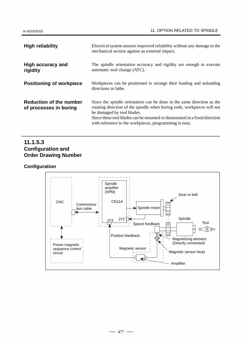
B–65162E/03 11. OPTION RELATED TO SPINDLE
477
Electrical system assures improved reliability without any damage to themechanical section against an external impact.
The spindle orientation accuracy and rigidity are enough to executeautomatic tool change (ATC).
Workpieces can be positioned to arrange their loading and unloadingdirections in lathe.
Since the spindle orientation can be done in the same direction as therotating direction of the spindle when boring ends, workpieces will notbe damaged by tool blades.Since these tool blades can be mounted or dismounted in a fixed directionwith reference to the workpieces, programming is easy.
Power magneticsequence controlcircuit
Spindleamplifier(SPM)
CN11A
Spindle motor
SpindleToolÅÅÅ
Magnetizing element(Directly connected)
Magnetic sensor head
CNC
Amplifier
Magnetic sensor
Speed feedback
Gear or belt
ÅÅÅÅ
Communica-tion cable
Position feedback
JY3 JY2
High reliability
High accuracy andrigidity
Positioning of workpiece
Reduction of the numberof processes in boring
11.1.5.3Configuration andOrder Drawing Number
Configuration
11. OPTION RELATED TO SPINDLE B–65162E/03
478
No. Item Description
1 Magneticsensor
Refer to item 12.3.2.
2 Stopposition
Stops when the center of the sensor head faces the cen-ter of the magnetizing element or the stop position checkscale of the magnetizing element.The stop position can be adjusted to within 1° by the cir-cuit.
3 Repeatability 0.2° or less.Excluding factors such as errors from the machine side,for example, setting errors.
4 Max. hold torque at orientation
Continuous rated torque of the AC spindle motor.
5 Range wherespindle can be orientated
Orientation stop position 240°
(1) DI SIGNALS (PMC to CNC)
(a) Spindle control signals
#7 #6 #5 #4 #3 #2 #1 #0FS0 FS15 FS16
MRDYA ORCMA SFRA SRVA CTH1A CTH2A TLMHA TLMLA: G229 G227 G070
First spindle control input signal
#7 #6 #5 #4 #3 #2 #1 #0FS0 FS15 FS16
MRDYB ORCMB SFRB SRVB CTH1B CTH2B TLMHB TLMLB: G223 G235 G074
Second spindle control input signal
(b) Orientation (fixed position stop) command (ORCMA)
This command signal is used to stop spindle movement at the presetposition to allow tool change and workpiece loading/unloading.
When this signal is specified as ”1” while the spindle is rotating, therotation decelerates immediately and the spindle stops at the presetposition.
When the orientation command is issued, set the spindleforward/reverse rotation command (SFRA, SRVA) to ”0” for safety.By means of this, the spindle will not start to rotate even in the unlikelyevent ORCMA becomes ”0” during tool change.
Set this signal to ”0” by the tool change completion signal orworkpiece loading/unloading completion signal.
Always set the orientation command signal to ”0” when turning onpower.
11.1.5.4Specifications
11.1.5.5Signal Explanation
B–65162E/03 11. OPTION RELATED TO SPINDLE
479
When an emergency stop occurs during orientation, the orientationcommand signal must be reset (”0”).Return the ATC arm to the safe position so that it will not be damagedif the spindle or tool rotates when the power is turned on.
(c) Clutch/gear signals (CTH1A, CTH2A)
When there are two or more speed change gear stages between thespindle and spindle motor, these signals are used to select a spindlecontrol parameter (position gain, gear ratio, velocity loop gain).
Depending on the clutch or gear state, make settings according to thetable below. Names such as HIGH GEAR are assigned only forconvenience. Arbitrary names may be assigned to the actual gears.
CTH1A CTH2A 0 0 : HIGH GEAR 0 1 : MEDIUM HIGH GEAR 1 0 : MEDIUM LOW GEAR 1 1 : LOW GEAR
(2) DO Signals (CNC to PMC)
(a) Spindle control signals
#7 #6 #5 #4 #3 #2 #1 #0FS0 FS15 FS16
ORARA TLMA LDT2A LDT1A SARA SDTA SSTA ALMA: F281 F229 F405
First spindle control output signal
#7 #6 #5 #4 #3 #2 #1 #0FS0 FS15 FS16
ORARB TLMB LDT2B LDT1B SARB SDTB SSTB ALMB: F285 F245 F049
Second spindle control output signals
(b) Orientation (fixed position stop) completion signal (ORARA)
When the orientation command is input and the spindle has stoppednear the preset fixed position (for example, within 1°), it becomes”1”.Condition for ORARA to become ”1”
Near to fixed position is set to the parameter.If the above 3 conditions are satisfied, the orientation complete signalis output.If the orientation completion signal is not issued within a set period oftime after the orientation command signal is input, it is considered tobe abnormal. So it should be detected by the power magnetic sequenceand an orientation alarm should be issued.Set the condition for judging that the spindle is near the fixed positionin the parameter used to specify the detection level for orientationcompletion.
Tool change or workpiece loading /unloading operations can be startedwhen this signal is ”1”.
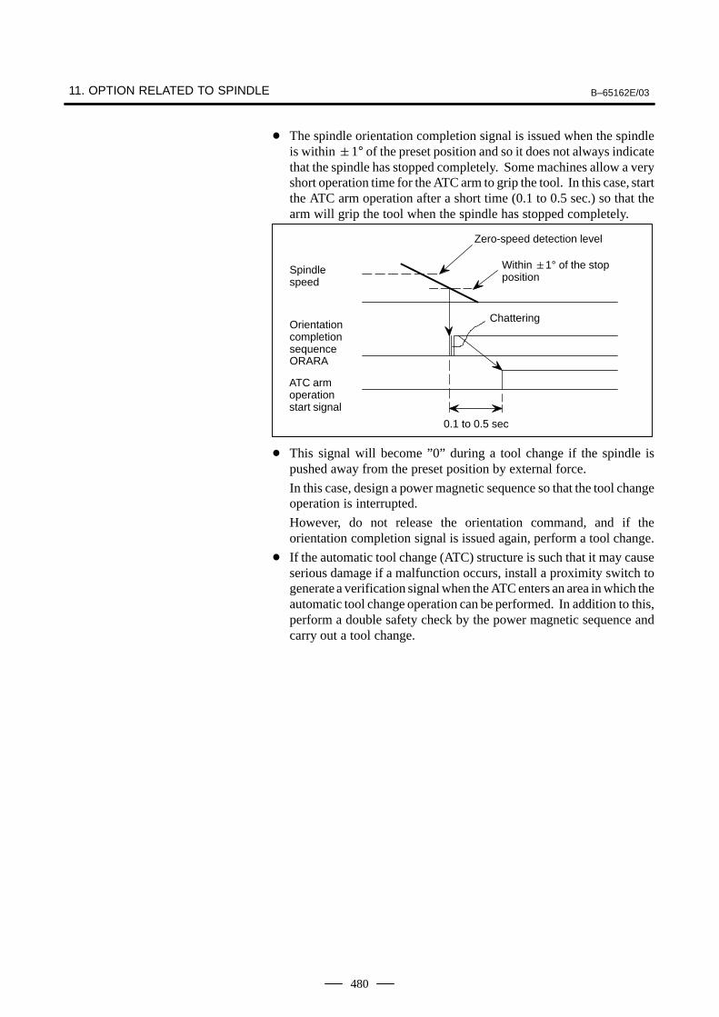
11. OPTION RELATED TO SPINDLE B–65162E/03
480
The spindle orientation completion signal is issued when the spindleis within 1° of the preset position and so it does not always indicatethat the spindle has stopped completely. Some machines allow a veryshort operation time for the ATC arm to grip the tool. In this case, startthe ATC arm operation after a short time (0.1 to 0.5 sec.) so that thearm will grip the tool when the spindle has stopped completely.
0.1 to 0.5 sec
Chattering
Spindlespeed
OrientationcompletionsequenceORARA
ATC armoperationstart signal
Zero-speed detection level
Within 1° of the stopposition
This signal will become ”0” during a tool change if the spindle ispushed away from the preset position by external force.
In this case, design a power magnetic sequence so that the tool changeoperation is interrupted.
However, do not release the orientation command, and if theorientation completion signal is issued again, perform a tool change.
If the automatic tool change (ATC) structure is such that it may causeserious damage if a malfunction occurs, install a proximity switch togenerate a verification signal when the ATC enters an area in which theautomatic tool change operation can be performed. In addition to this,perform a double safety check by the power magnetic sequence andcarry out a tool change.
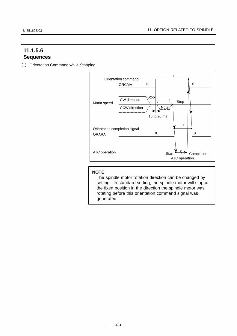
B–65162E/03 11. OPTION RELATED TO SPINDLE
481
(1) Orientation Command while Stopping
CompletionATC operation
Stop
0
Start
0
1
0
Note
Orientation command
ORCMA
CCW directionMotor speed
CW direction
Orientation completion signal
ORARA
ATC operation
Stop
15 to 20 ms
1
0
NOTEThe spindle motor rotation direction can be changed bysetting. In standard setting, the spindle motor will stop atthe fixed position in the direction the spindle motor wasrotating before this orientation command signal wasgenerated.
11.1.5.6Sequences
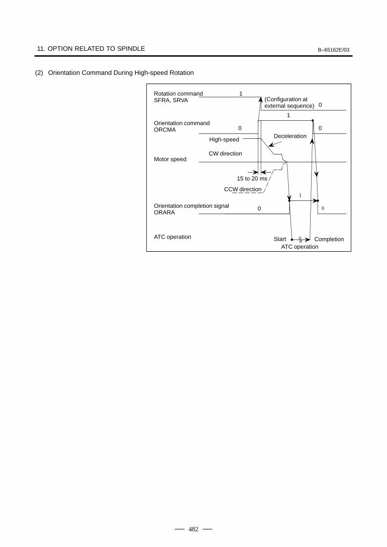
11. OPTION RELATED TO SPINDLE B–65162E/03
482
(2) Orientation Command During High-speed Rotation
CompletionATC operation
Deceleration
15 to 20 ms
CCW direction
0(Configuration atexternal sequence)
1
0
1
0
1
0
0
Start
High-speed
Rotation commandSFRA, SRVA
Orientation commandORCMA
ATC operation
Motor speed
Orientation completion signalORARA
CW direction
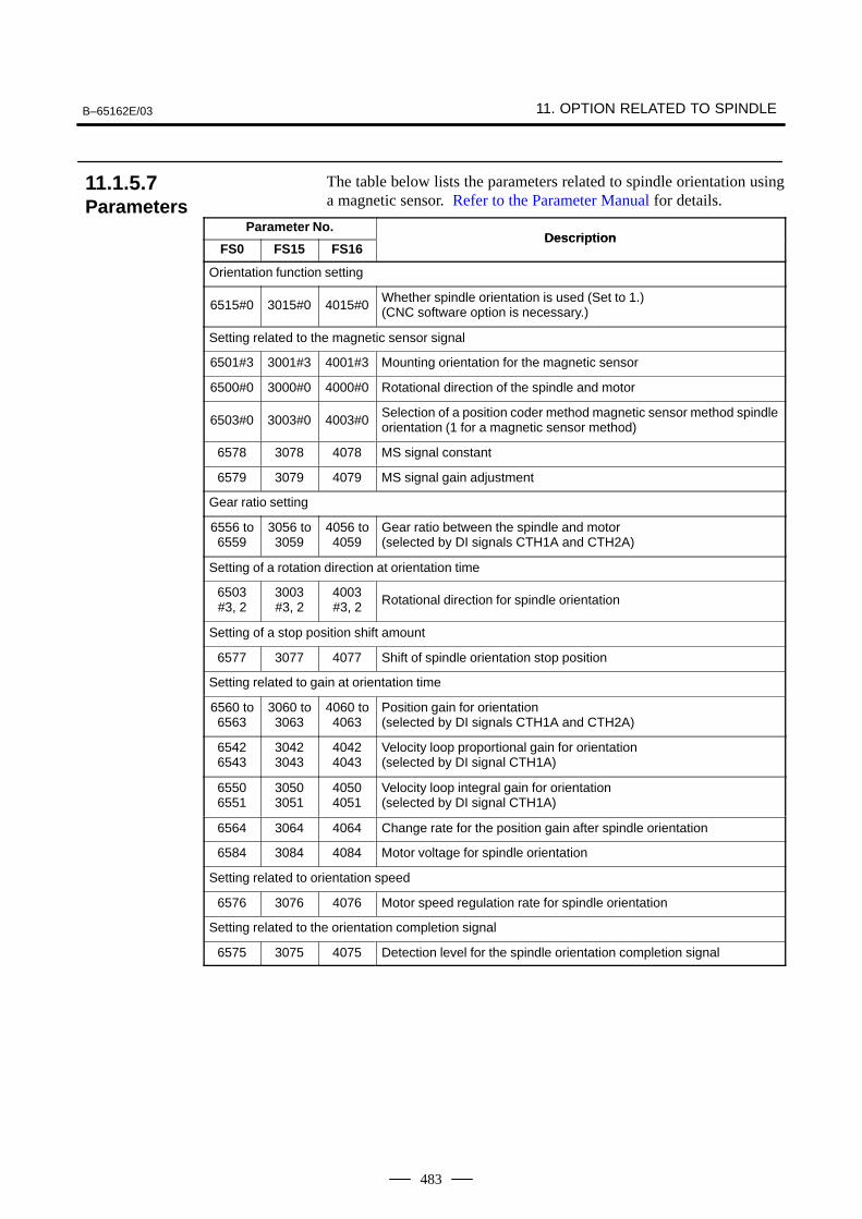
B–65162E/03 11. OPTION RELATED TO SPINDLE
483
The table below lists the parameters related to spindle orientation usinga magnetic sensor. Refer to the Parameter Manual for details.
Parameter No.Description
FS0 FS15 FS16Description
Orientation function setting
6515#0 3015#0 4015#0Whether spindle orientation is used (Set to 1.)(CNC software option is necessary.)
Setting related to the magnetic sensor signal
6501#3 3001#3 4001#3 Mounting orientation for the magnetic sensor
6500#0 3000#0 4000#0 Rotational direction of the spindle and motor
6503#0 3003#0 4003#0Selection of a position coder method magnetic sensor method spindleorientation (1 for a magnetic sensor method)
6578 3078 4078 MS signal constant
6579 3079 4079 MS signal gain adjustment
Gear ratio setting
6556 to6559
3056 to3059
4056 to4059
Gear ratio between the spindle and motor(selected by DI signals CTH1A and CTH2A)
Setting of a rotation direction at orientation time
6503#3, 2
3003#3, 2
4003#3, 2 Rotational direction for spindle orientation
Setting of a stop position shift amount
6577 3077 4077 Shift of spindle orientation stop position
Setting related to gain at orientation time
6560 to6563
3060 to3063
4060 to4063
Position gain for orientation(selected by DI signals CTH1A and CTH2A)
65426543
30423043
40424043
Velocity loop proportional gain for orientation(selected by DI signal CTH1A)
65506551
30503051
40504051
Velocity loop integral gain for orientation(selected by DI signal CTH1A)
6564 3064 4064 Change rate for the position gain after spindle orientation
6584 3084 4084 Motor voltage for spindle orientation
Setting related to orientation speed
6576 3076 4076 Motor speed regulation rate for spindle orientation
Setting related to the orientation completion signal
6575 3075 4075 Detection level for the spindle orientation completion signal
11.1.5.7Parameters
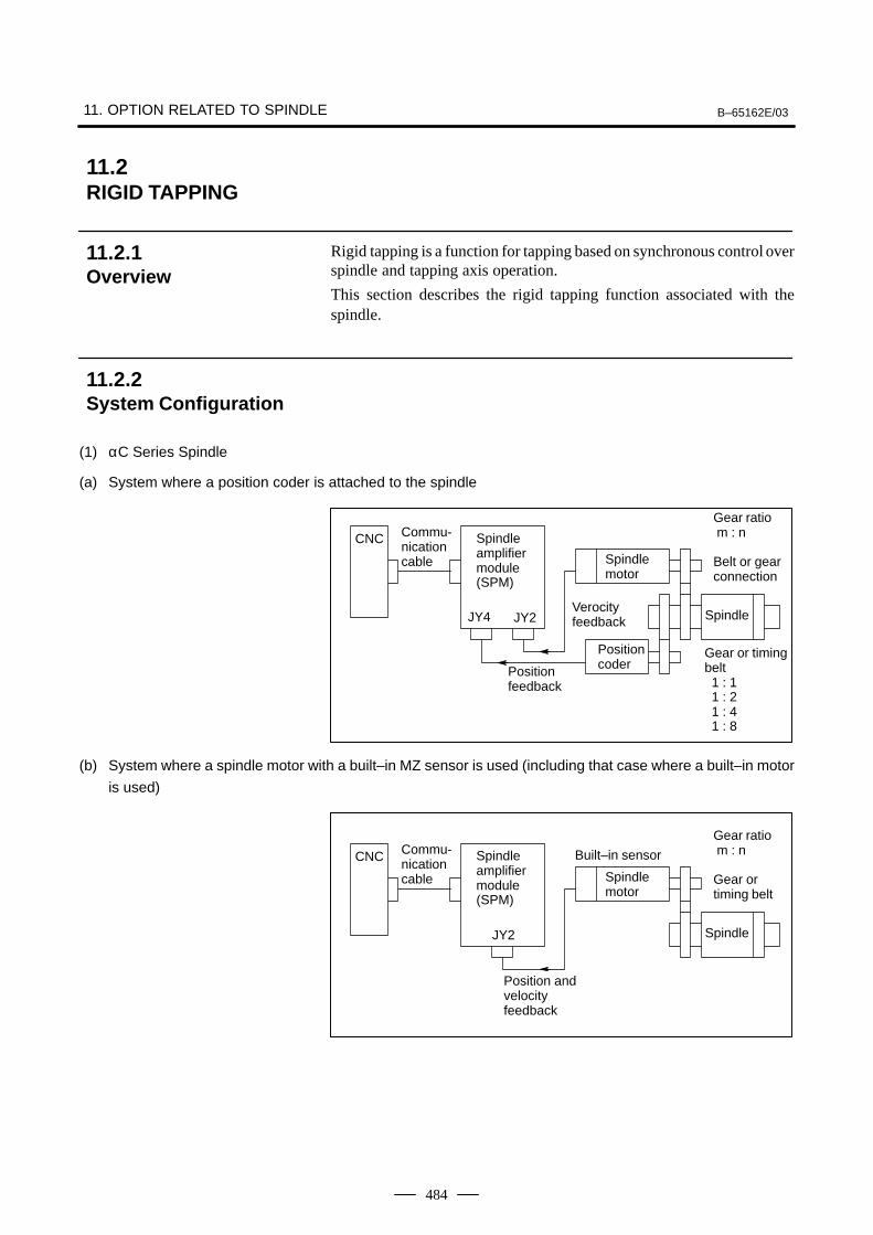
11. OPTION RELATED TO SPINDLE B–65162E/03
484
Rigid tapping is a function for tapping based on synchronous control overspindle and tapping axis operation.
This section describes the rigid tapping function associated with thespindle.
(1) αC Series Spindle
(a) System where a position coder is attached to the spindle
Commu-nicationcable
CNC
Spindle motor
JY4 JY2
Positioncoder
Spindle
Positionfeedback
Verocityfeedback
Gear ratio m : n
Belt or gearconnection
Spindle amplifier module (SPM)
Gear or timingbelt 1 : 1 1 : 2 1 : 4 1 : 8
(b) System where a spindle motor with a built–in MZ sensor is used (including that case where a built–in motor
is used)
Commu-nicationcable
CNC
Spindle motor
JY2 Spindle
Position and velocityfeedback
Gear ratio m : n
Gear or timing belt
Spindle amplifier module (SPM)
Built–in sensor
11.2RIGID TAPPING
11.2.1Overview
11.2.2System Configuration
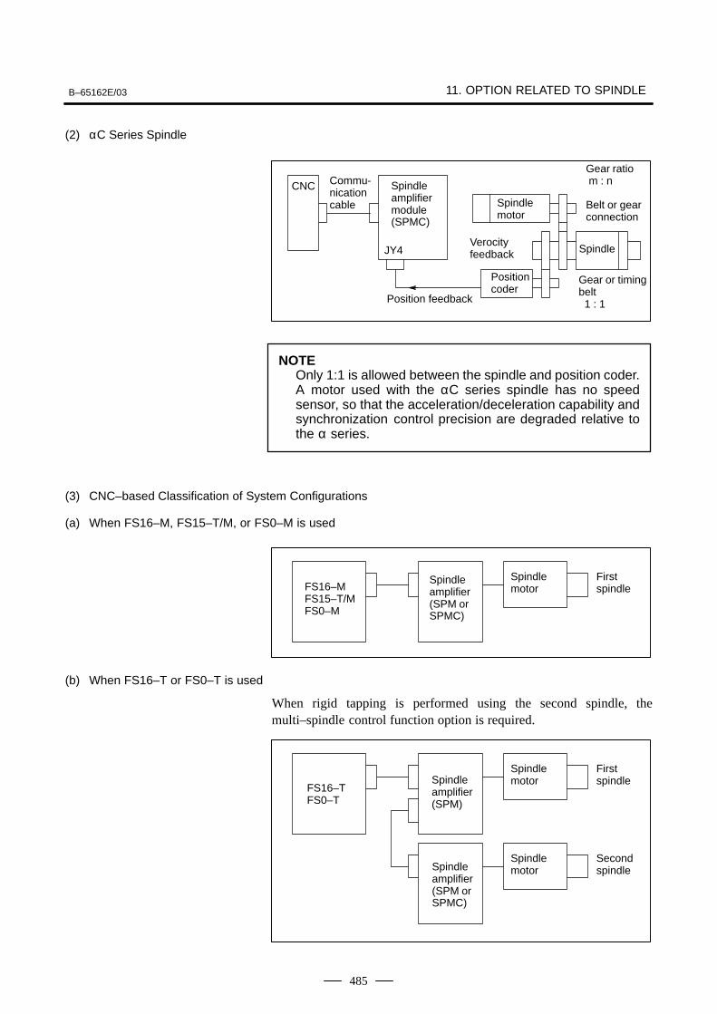
B–65162E/03 11. OPTION RELATED TO SPINDLE
485
(2) αC Series Spindle
Commu-nicationcable
CNC
Spindle motor
JY4
Positioncoder
Spindle
Position feedback
Verocityfeedback
Gear ratio m : n
Belt or gearconnection
Spindle amplifier module (SPMC)
Gear or timingbelt 1 : 1
NOTEOnly 1:1 is allowed between the spindle and position coder.A motor used with the αC series spindle has no speedsensor, so that the acceleration/deceleration capability andsynchronization control precision are degraded relative tothe α series.
(3) CNC–based Classification of System Configurations
(a) When FS16–M, FS15–T/M, or FS0–M is used
FS16–MFS15–T/MFS0–M
Spindle motor
Spindleamplifier(SPM orSPMC)
Firstspindle
(b) When FS16–T or FS0–T is used
When rigid tapping is performed using the second spindle, themulti–spindle control function option is required.
FS16–TFS0–T
Spindle motorSpindle
amplifier (SPM)
Firstspindle
Spindle motor
SecondspindleSpindle
amplifier(SPM orSPMC)
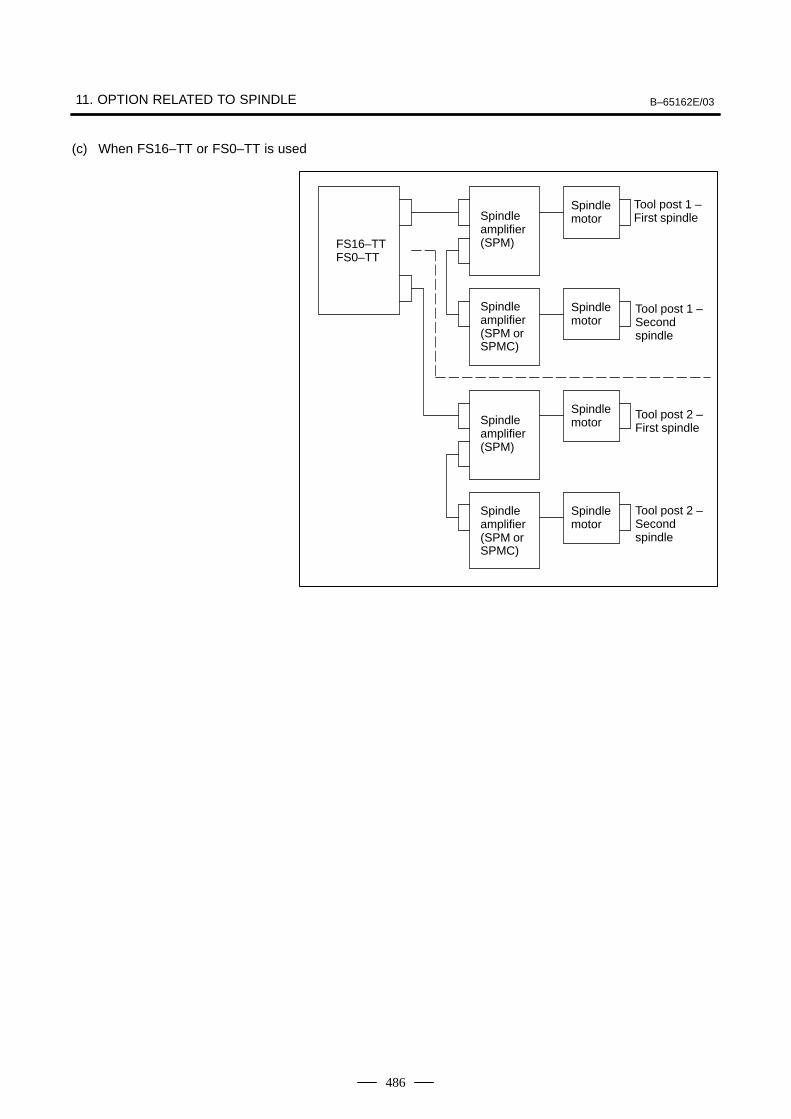
11. OPTION RELATED TO SPINDLE B–65162E/03
486
(c) When FS16–TT or FS0–TT is used
FS16–TTFS0–TT
Spindle motorSpindle
amplifier (SPM)
Spindle motor
Spindle amplifier (SPM orSPMC)
Spindle motorSpindle
amplifier (SPM)
Spindle motor
Spindle amplifier (SPM orSPMC)
Tool post 1 –First spindle
Tool post 1 –Secondspindle
Tool post 2 –First spindle
Tool post 2 –Secondspindle
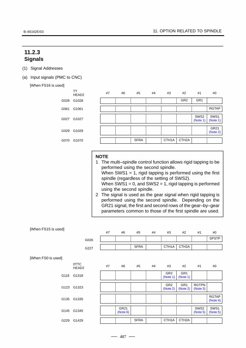
B–65162E/03 11. OPTION RELATED TO SPINDLE
487
(1) Signal Addresses
(a) Input signals (PMC to CNC)
#7 #6 #5 #4 #3 #2 #1 #0TTHEAD2
GR2 GR1G028 G1028
SFRA CTH1A CTH2AG070 G1070
SWS2(Note 1)
SWS1(Note 1)G027 G1027
RGTAPG061 G1061
GR21(Note 2)G029 G1029
[When FS16 is used]
NOTE1 The multi–spindle control function allows rigid tapping to be
performed using the second spindle.When SWS1 = 1, rigid tapping is performed using the firstspindle (regardless of the setting of SWS2).When SWS1 = 0, and SWS2 = 1, rigid tapping is performedusing the second spindle.
2 The signal is used as the gear signal when rigid tapping isperformed using the second spindle. Depending on theGR21 signal, the first and second rows of the gear–by–gearparameters common to those of the first spindle are used.
#7 #6 #5 #4 #3 #2 #1 #0
SFRA CTH1A CTH2AG227
SPSTPG026
[When FS15 is used]
#7 #6 #5 #4 #3 #2 #1 #00TTCHEAD2
GR2(Note 1)
GR1(Note 1)G118 G1318
SFRA CTH1A CTH2AG229 G1429
GR2(Note 2)
GR1(Note 2)
RGTPN(Note 3)G123 G1323
RGTAP(Note 4)G135 G1335
GR21(Note 6)
SWS2(Note 5)
SWS1(Note 5)G145 G1345
[When FS0 is used]
11.2.3Signals
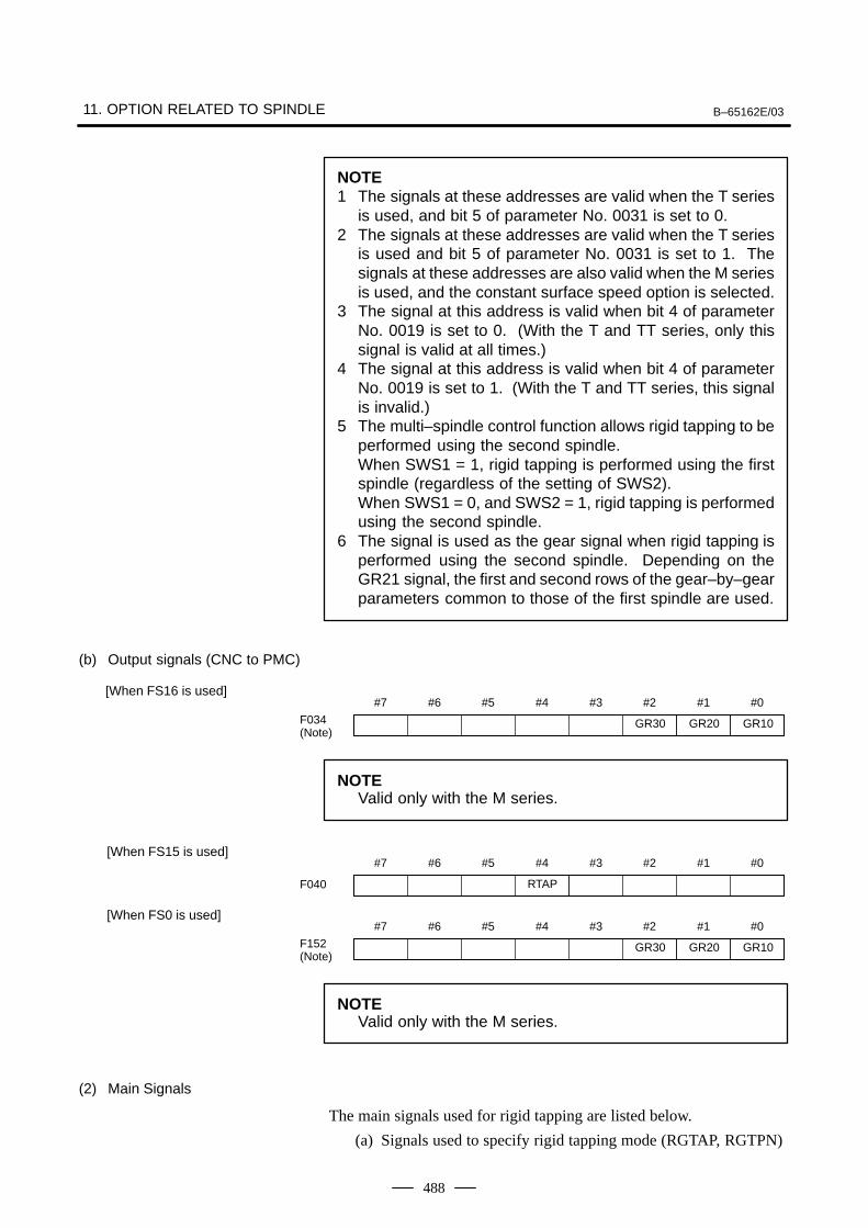
11. OPTION RELATED TO SPINDLE B–65162E/03
488
NOTE1 The signals at these addresses are valid when the T series
is used, and bit 5 of parameter No. 0031 is set to 0.2 The signals at these addresses are valid when the T series
is used and bit 5 of parameter No. 0031 is set to 1. Thesignals at these addresses are also valid when the M seriesis used, and the constant surface speed option is selected.
3 The signal at this address is valid when bit 4 of parameterNo. 0019 is set to 0. (With the T and TT series, only thissignal is valid at all times.)
4 The signal at this address is valid when bit 4 of parameterNo. 0019 is set to 1. (With the T and TT series, this signalis invalid.)
5 The multi–spindle control function allows rigid tapping to beperformed using the second spindle.When SWS1 = 1, rigid tapping is performed using the firstspindle (regardless of the setting of SWS2).When SWS1 = 0, and SWS2 = 1, rigid tapping is performedusing the second spindle.
6 The signal is used as the gear signal when rigid tapping isperformed using the second spindle. Depending on theGR21 signal, the first and second rows of the gear–by–gearparameters common to those of the first spindle are used.
(b) Output signals (CNC to PMC)
#7 #6 #5 #4 #3 #2 #1 #0
GR30 GR20 GR10F034(Note)
[When FS16 is used]
NOTEValid only with the M series.
#7 #6 #5 #4 #3 #2 #1 #0
RTAPF040
[When FS15 is used]
#7 #6 #5 #4 #3 #2 #1 #0
GR30 GR20 GR10F152(Note)
[When FS0 is used]
NOTEValid only with the M series.
(2) Main Signals
The main signals used for rigid tapping are listed below.
(a) Signals used to specify rigid tapping mode (RGTAP, RGTPN)
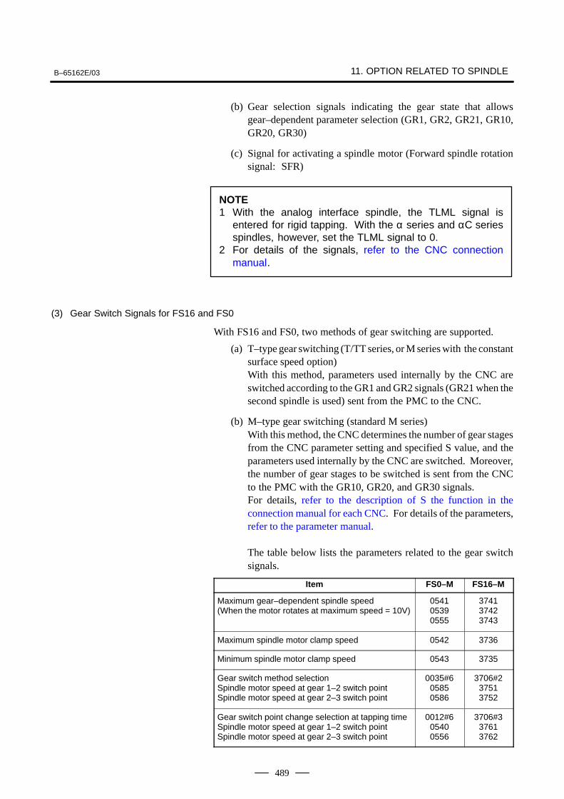
B–65162E/03 11. OPTION RELATED TO SPINDLE
489
(b) Gear selection signals indicating the gear state that allowsgear–dependent parameter selection (GR1, GR2, GR21, GR10,GR20, GR30)
(c) Signal for activating a spindle motor (Forward spindle rotationsignal: SFR)
NOTE1 With the analog interface spindle, the TLML signal is
entered for rigid tapping. With the α series and αC seriesspindles, however, set the TLML signal to 0.
2 For details of the signals, refer to the CNC connectionmanual.
(3) Gear Switch Signals for FS16 and FS0
With FS16 and FS0, two methods of gear switching are supported.
(a) T–type gear switching (T/TT series, or M series with the constantsurface speed option)With this method, parameters used internally by the CNC areswitched according to the GR1 and GR2 signals (GR21 when thesecond spindle is used) sent from the PMC to the CNC.
(b) M–type gear switching (standard M series)With this method, the CNC determines the number of gear stagesfrom the CNC parameter setting and specified S value, and theparameters used internally by the CNC are switched. Moreover,the number of gear stages to be switched is sent from the CNCto the PMC with the GR10, GR20, and GR30 signals.For details, refer to the description of S the function in theconnection manual for each CNC. For details of the parameters,refer to the parameter manual.
The table below lists the parameters related to the gear switchsignals.
Item FS0–M FS16–M
Maximum gear–dependent spindle speed (When the motor rotates at maximum speed = 10V)
054105390555
374137423743
Maximum spindle motor clamp speed 0542 3736
Minimum spindle motor clamp speed 0543 3735
Gear switch method selectionSpindle motor speed at gear 1–2 switch point Spindle motor speed at gear 2–3 switch point
0035#605850586
3706#237513752
Gear switch point change selection at tapping timeSpindle motor speed at gear 1–2 switch point Spindle motor speed at gear 2–3 switch point
0012#605400556
3706#337613762
11. OPTION RELATED TO SPINDLE B–65162E/03
490
(4) Rigid Tapping Using the Second Spindle with the T/TT Series of FS16 and FS0
The multi–spindle control function option is required.
(a) The following selection is made according to the SWS1 andSWS2 signals of the multi–spindle control function: When SWS = 1 (regardless of the setting of SWS2)
→ Rigid tapping using the first spindle When SWS = 1 and SWS2 = 1
→ Rigid tapping using the second spindle
(b) The GR21 signal (two gear stages only) is used as the gear switchsignal for rigid tapping using the second spindle.For the second spindle, the first and second rows of theparameters common to the first spindle are used, depending onthe state of the GR21 signal.
For details of the sequence, refer to the CNC connection manual.
(1) For the Series 16i/18i/21i, refer to the following manual:Section 9.11 of the FANUC Series 16i/18i/21i Connection Manual(Function) (B–63003EN–1)
(2) For the Series 16/18, refer to the following manual:Section 9.11 of the FANUC Series 16/18 Connection Manual(Mechanical) (B–62753EN–1)
(3) For the Series 15, refer to the following manual:Section 2.3.51 of the FANUC Series 15 Connection Manual (BMIInterface) (B–61213E–2)
(4) For the Series 0–C, refer to the following manual:Appendix D and Section 1.2 of the FANUC Series 0 ConnectionManual (B–61393E)
11.2.4Sequence
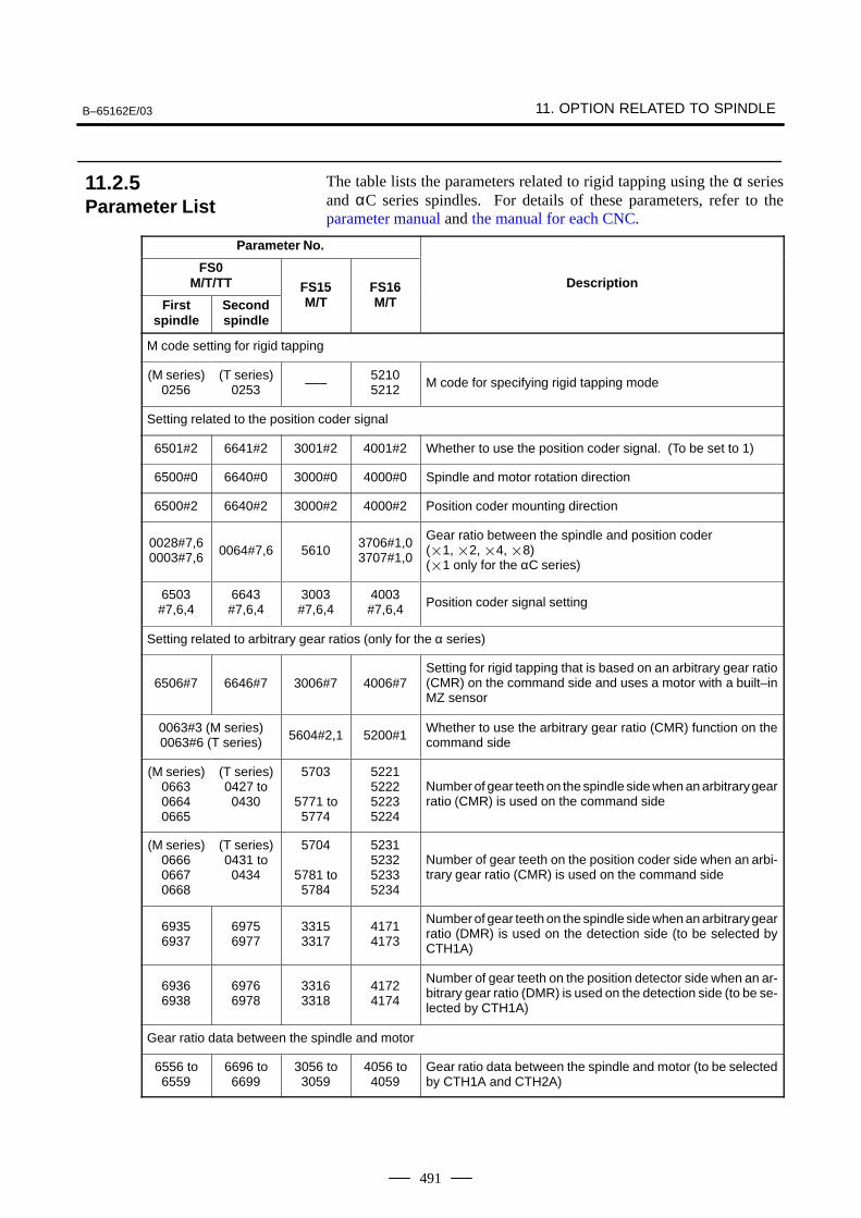
B–65162E/03 11. OPTION RELATED TO SPINDLE
491
The table lists the parameters related to rigid tapping using the α seriesand αC series spindles. For details of these parameters, refer to theparameter manual and the manual for each CNC.
Parameter No.
FS0M/T/TT FS15 FS16 Description
Firstspindle
Secondspindle
FS15M/T
FS16M/T
M code setting for rigid tapping
(M series)0256
(T series)0253 –––
52105212 M code for specifying rigid tapping mode
Setting related to the position coder signal
6501#2 6641#2 3001#2 4001#2 Whether to use the position coder signal. (To be set to 1)
6500#0 6640#0 3000#0 4000#0 Spindle and motor rotation direction
6500#2 6640#2 3000#2 4000#2 Position coder mounting direction
0028#7,60003#7,6 0064#7,6 5610
3706#1,03707#1,0
Gear ratio between the spindle and position coder (1, 2, 4, 8)(1 only for the αC series)
6503#7,6,4
6643#7,6,4
3003#7,6,4
4003#7,6,4 Position coder signal setting
Setting related to arbitrary gear ratios (only for the α series)
6506#7 6646#7 3006#7 4006#7Setting for rigid tapping that is based on an arbitrary gear ratio(CMR) on the command side and uses a motor with a built–inMZ sensor
0063#3 (M series)0063#6 (T series) 5604#2,1 5200#1
Whether to use the arbitrary gear ratio (CMR) function on thecommand side
(M series)066306640665
(T series)0427 to0430
5703
5771 to5774
5221522252235224
Number of gear teeth on the spindle side when an arbitrary gearratio (CMR) is used on the command side
(M series)066606670668
(T series)0431 to0434
5704
5781 to5784
5231523252335234
Number of gear teeth on the position coder side when an arbi-trary gear ratio (CMR) is used on the command side
69356937
69756977
33153317
41714173
Number of gear teeth on the spindle side when an arbitrary gearratio (DMR) is used on the detection side (to be selected byCTH1A)
69366938
69766978
33163318
41724174
Number of gear teeth on the position detector side when an ar-bitrary gear ratio (DMR) is used on the detection side (to be se-lected by CTH1A)
Gear ratio data between the spindle and motor
6556 to6559
6696 to6699
3056 to3059
4056 to4059
Gear ratio data between the spindle and motor (to be selectedby CTH1A and CTH2A)
11.2.5Parameter List
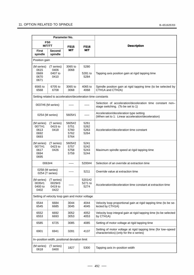
11. OPTION RELATED TO SPINDLE B–65162E/03
492
Parameter No.
DescriptionFS0
M/T/TT DescriptionFS16M/T
FS15M/TFirst
spindle
DescriptionFS16M/T
FS15M/TSecond
spindle
Position gain
(M series)0615066906700671
(T series)0406
0407 to0410
3065 to3068
5280
5281 to5284
Tapping axis position gain at rigid tapping time
6565 to6568
6705 to6708
3065 to3068
4065 to4068
Spindle position gain at rigid tapping time (to be selected byCTH1A and CTH2A)
Setting related to acceleration/deceleration time constants
0037#6 (M series) ––– –––Selection of acceleration/deceleration time constant non–stage switching. (To be set to 1)
0254 (M series) 5605#1 –––Acceleration/deceleration type setting(When set to 1: Linear acceleration/deceleration)
(M series)0077#1
061306920693
(T series)0415 to0418
5605#25751576057625764
5261526252635264
Acceleration/deceleration time constant
(M series)0077#1
061706940695
(T series)0423 to0426
5605#2575757585759
5241524252435244
Maximum spindle speed at rigid tapping time
0063#4 ––– 5200#4 Selection of an override at extraction time
0258 (M series)0254 (T series) ––– 5211 Override value at extraction time
(M series)0035#10400 to0402
(T series)0029#30419 to0422
–––
5201#25271 to5274
Acceleration/deceleration time constant at extraction time
Setting of velocity loop gain and motor voltage
65446545
66846685
30443045
40444045
Velocity loop proportional gain at rigid tapping time (to be se-lected by CTH1A)
65526553
66926693
30523053
40524053
Velocity loop integral gain at rigid tapping time (to be selectedby CTH1A)
6585 6725 3085 4085 Setting of motor voltage at rigid tapping time
6901 6941 3281 4137Setting of motor voltage at rigid tapping time (for low–speedcharacteristics) (only for the α series)
In–position width, positional deviation limit
(M series)0618
(T series)0400 1827 5300 Tapping axis in–position width
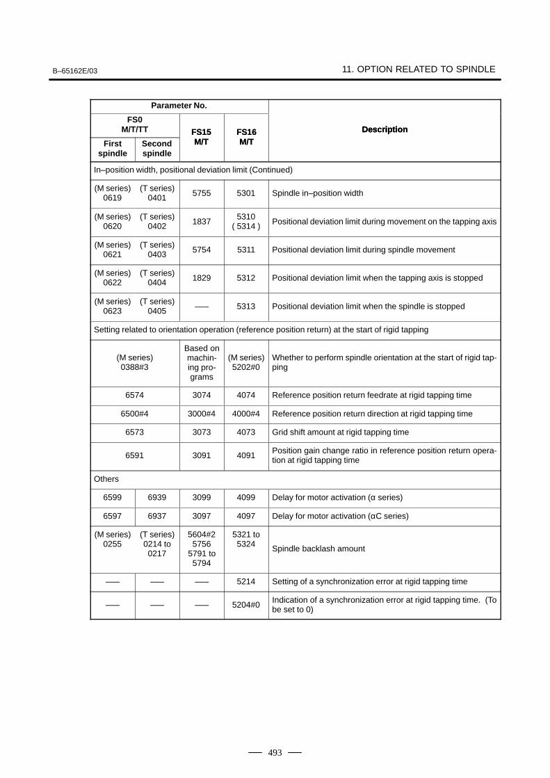
B–65162E/03 11. OPTION RELATED TO SPINDLE
493
Parameter No.
DescriptionFS0
M/T/TT DescriptionFS16M/T
FS15M/TFirst
spindle
DescriptionFS16M/T
FS15M/TSecond
spindle
In–position width, positional deviation limit (Continued)
(M series)0619
(T series)0401 5755 5301 Spindle in–position width
(M series)0620
(T series)0402 1837
5310( 5314 ) Positional deviation limit during movement on the tapping axis
(M series)0621
(T series)0403 5754 5311 Positional deviation limit during spindle movement
(M series)0622
(T series)0404 1829 5312 Positional deviation limit when the tapping axis is stopped
(M series)0623
(T series)0405 ––– 5313 Positional deviation limit when the spindle is stopped
Setting related to orientation operation (reference position return) at the start of rigid tapping
(M series)0388#3
Based onmachin-ing pro-grams
(M series)5202#0
Whether to perform spindle orientation at the start of rigid tap-ping
6574 3074 4074 Reference position return feedrate at rigid tapping time
6500#4 3000#4 4000#4 Reference position return direction at rigid tapping time
6573 3073 4073 Grid shift amount at rigid tapping time
6591 3091 4091Position gain change ratio in reference position return opera-tion at rigid tapping time
Others
6599 6939 3099 4099 Delay for motor activation (α series)
6597 6937 3097 4097 Delay for motor activation (αC series)
(M series)0255
(T series)0214 to0217
5604#25756
5791 to5794
5321 to5324 Spindle backlash amount
––– ––– ––– 5214 Setting of a synchronization error at rigid tapping time
––– ––– ––– 5204#0Indication of a synchronization error at rigid tapping time. (Tobe set to 0)
11. OPTION RELATED TO SPINDLE B–65162E/03
494
Cs contouring control is a function enabling servo control of the spindleusing a high–resolution magnetic pulse coder or high–resolution positioncoder.This function can be used for positioning the spindle and the interpolationbetween the spindle and another servo axis. Linear interpolation andcircular interpolation are supported.
NOTEThis function is not supported for the αC series spindle.
11.3Cs CONTOURING CONTROL
11.3.1Outline
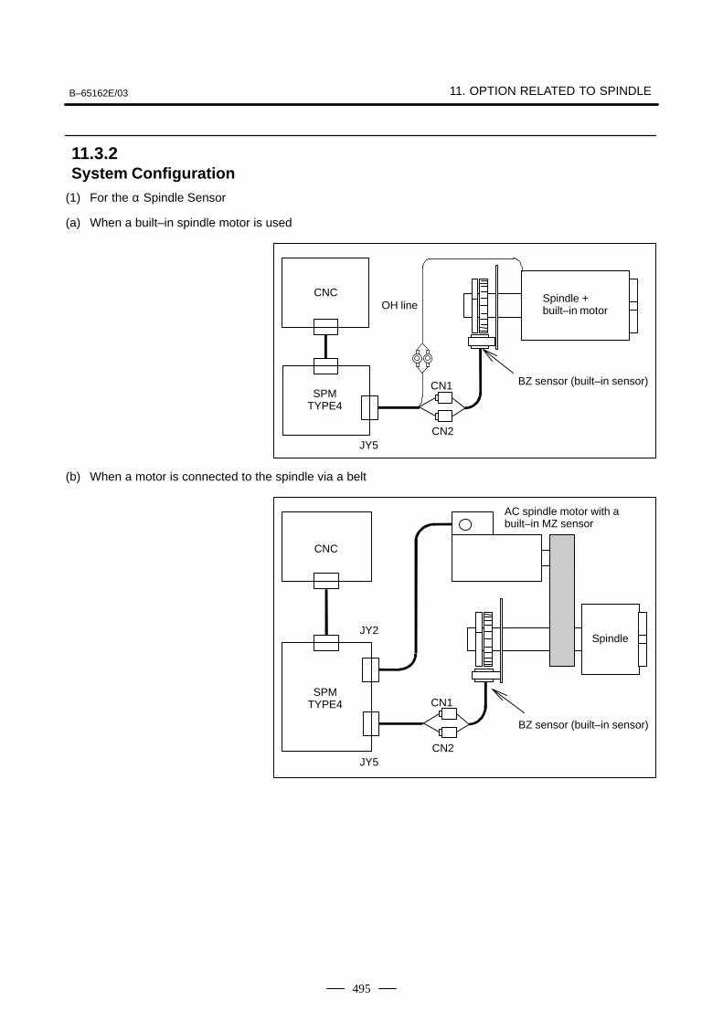
B–65162E/03 11. OPTION RELATED TO SPINDLE
495
(1) For the α Spindle Sensor
(a) When a built–in spindle motor is used
CN1
CNC
SPMTYPE4
JY5CN2
OH lineSpindle + built–in motor
BZ sensor (built–in sensor)
(b) When a motor is connected to the spindle via a belt
CN1
CNC
SPMTYPE4
JY5CN2
Spindle
BZ sensor (built–in sensor)
AC spindle motor with abuilt–in MZ sensor
JY2
11.3.2System Configuration
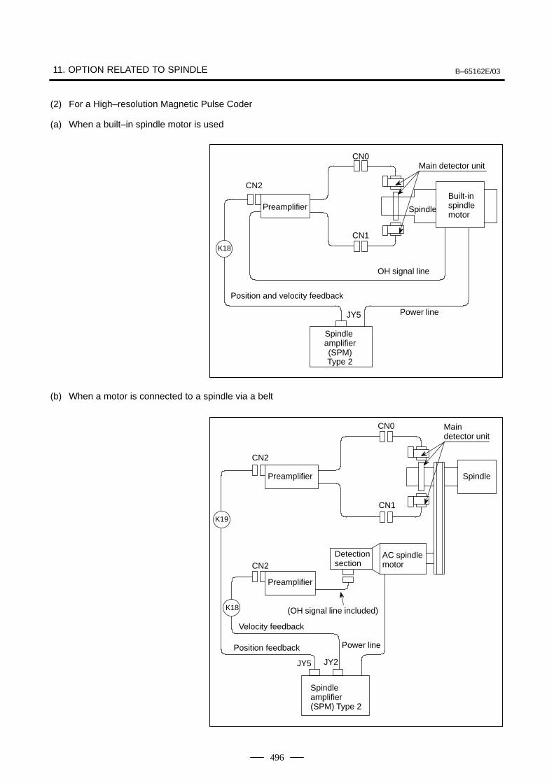
11. OPTION RELATED TO SPINDLE B–65162E/03
496
(2) For a High–resolution Magnetic Pulse Coder
(a) When a built–in spindle motor is used
OH signal line
Power line
Preamplifier
JY5
CN2
Spindle
CN0
CN1
Built-inspindlemotor
K18
Position and velocity feedback
Main detector unit
Spindle amplifier(SPM)Type 2
(b) When a motor is connected to a spindle via a belt
Power linePosition feedback
Velocity feedback
Spindle amplifier (SPM) Type 2
Preamplifier
K19
JY2
CN2
CN2
AC spindle motor
Detection section
Spindle
(OH signal line included)
CN0
CN1
K18
Preamplifier
JY5
Main detector unit
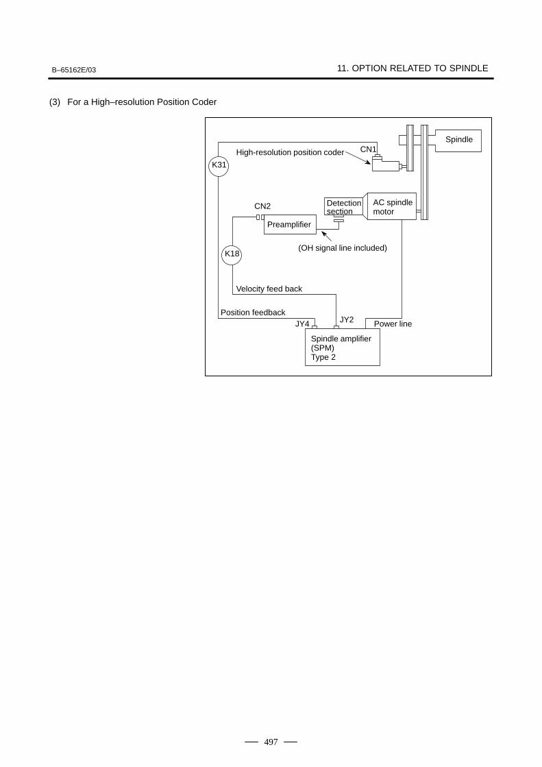
B–65162E/03 11. OPTION RELATED TO SPINDLE
497
(3) For a High–resolution Position Coder
Detection section
Spindle
AC spindlemotor
Preamplifier
CN2
Velocity feed back
Spindle amplifier (SPM)Type 2
Power line
(OH signal line included)
High-resolution position coder
Position feedback
K31
K18
JY4 JY2
CN1
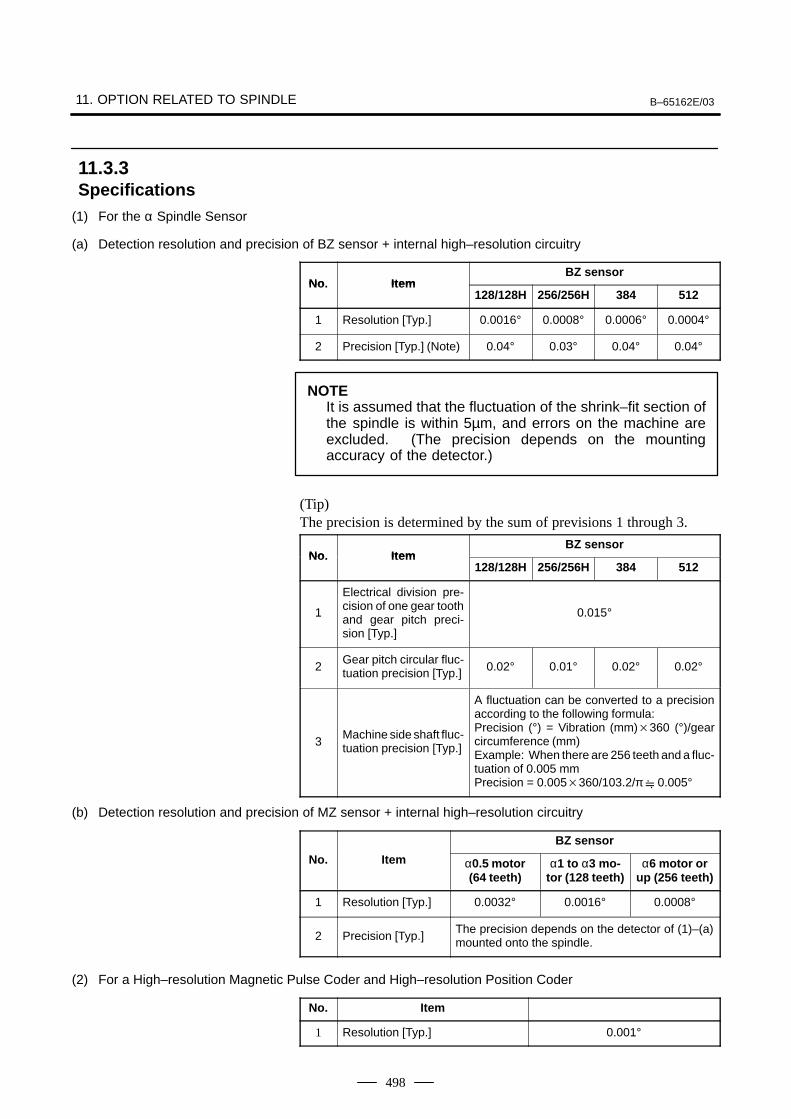
11. OPTION RELATED TO SPINDLE B–65162E/03
498
(1) For the α Spindle Sensor
(a) Detection resolution and precision of BZ sensor + internal high–resolution circuitry
No ItemBZ sensor
No. Item128/128H 256/256H 384 512
1 Resolution [Typ.] 0.0016° 0.0008° 0.0006° 0.0004°
2 Precision [Typ.] (Note) 0.04° 0.03° 0.04° 0.04°
NOTEIt is assumed that the fluctuation of the shrink–fit section ofthe spindle is within 5µm, and errors on the machine areexcluded. (The precision depends on the mountingaccuracy of the detector.)
(Tip)The precision is determined by the sum of previsions 1 through 3.
No ItemBZ sensor
No. Item128/128H 256/256H 384 512
1
Electrical division pre-cision of one gear toothand gear pitch preci-sion [Typ.]
0.015°
2Gear pitch circular fluc-tuation precision [Typ.] 0.02° 0.01° 0.02° 0.02°
3Machine side shaft fluc-tuation precision [Typ.]
A fluctuation can be converted to a precisionaccording to the following formula:Precision (°) = Vibration (mm)360 (°)/gearcircumference (mm)Example: When there are 256 teeth and a fluc-tuation of 0.005 mmPrecision = 0.005360/103.2/π 0.005°
(b) Detection resolution and precision of MZ sensor + internal high–resolution circuitry
BZ sensor
No. Item α0.5 motor(64 teeth)
α1 to α3 mo-tor (128 teeth)
α6 motor orup (256 teeth)
1 Resolution [Typ.] 0.0032° 0.0016° 0.0008°
2 Precision [Typ.]The precision depends on the detector of (1)–(a)mounted onto the spindle.
(2) For a High–resolution Magnetic Pulse Coder and High–resolution Position Coder
No. Item
1 Resolution [Typ.] 0.001°
11.3.3Specifications
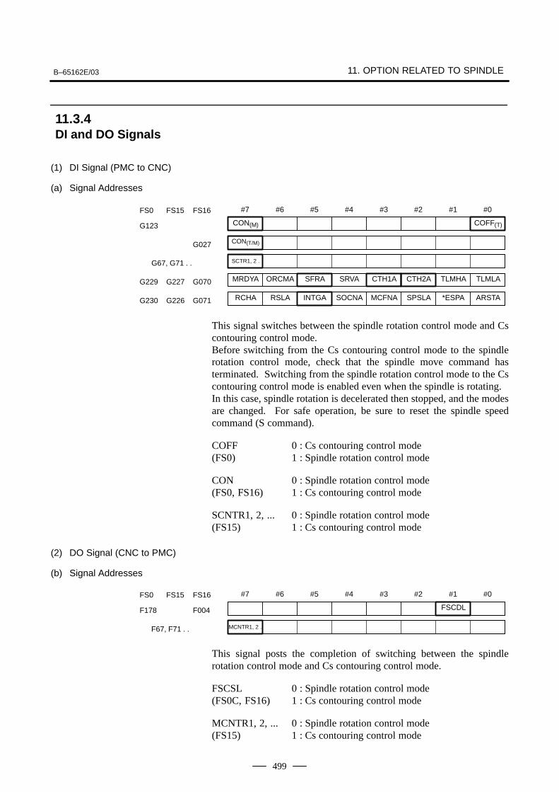
B–65162E/03 11. OPTION RELATED TO SPINDLE
499
(1) DI Signal (PMC to CNC)
(a) Signal Addresses
#7
CON(M)
#6 #5 #4 #3 #2 #1 #0
COFF(T)G123
FS0 FS15 FS16
MRDYA ORCMA SFRA SRVA CTH1A CTH2A TLMHA TLMLA
RCHA RSLA INTGA SOCNA MCFNA SPSLA *ESPA ARSTA
CON(T/M)G027
SCTR1, 2 . G67, G71 . .
G229 G227 G070
G230 G226 G071
This signal switches between the spindle rotation control mode and Cscontouring control mode.Before switching from the Cs contouring control mode to the spindlerotation control mode, check that the spindle move command hasterminated. Switching from the spindle rotation control mode to the Cscontouring control mode is enabled even when the spindle is rotating.In this case, spindle rotation is decelerated then stopped, and the modesare changed. For safe operation, be sure to reset the spindle speedcommand (S command).
COFF 0 : Cs contouring control mode(FS0) 1 : Spindle rotation control mode
CON 0 : Spindle rotation control mode(FS0, FS16) 1 : Cs contouring control mode
SCNTR1, 2, ... 0 : Spindle rotation control mode(FS15) 1 : Cs contouring control mode
(2) DO Signal (CNC to PMC)
(b) Signal Addresses
#7 #6 #5 #4 #3 #2 #1
FSCDL
#0
F178 F004
FS0 FS15 FS16
MCNTR1, 2 . F67, F71 . .
This signal posts the completion of switching between the spindlerotation control mode and Cs contouring control mode.
FSCSL 0 : Spindle rotation control mode(FS0C, FS16) 1 : Cs contouring control mode
MCNTR1, 2, ... 0 : Spindle rotation control mode(FS15) 1 : Cs contouring control mode
11.3.4DI and DO Signals
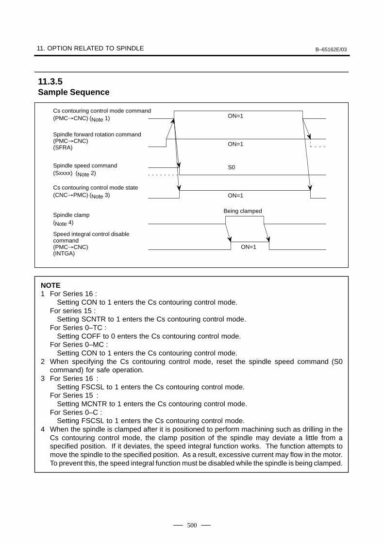
11. OPTION RELATED TO SPINDLE B–65162E/03
500
ON=1
Being clamped
ON=1
S0
ON=1
ON=1Cs contouring control mode command(PMCCNC) (Note 1)
Spindle forward rotation command(PMCCNC) (SFRA)
Spindle speed command(Sxxxx) (Note 2)
Cs contouring control mode state(CNCPMC) (Note 3)
Spindle clamp(Note 4)
Speed integral control disablecommand(PMCCNC) (INTGA)
NOTE1 For Series 16 :
Setting CON to 1 enters the Cs contouring control mode.For series 15 :
Setting SCNTR to 1 enters the Cs contouring control mode.For Series 0–TC :
Setting COFF to 0 enters the Cs contouring control mode.For Series 0–MC :
Setting CON to 1 enters the Cs contouring control mode.2 When specifying the Cs contouring control mode, reset the spindle speed command (S0
command) for safe operation.3 For Series 16 :
Setting FSCSL to 1 enters the Cs contouring control mode.For Series 15 :
Setting MCNTR to 1 enters the Cs contouring control mode.For Series 0–C :
Setting FSCSL to 1 enters the Cs contouring control mode.4 When the spindle is clamped after it is positioned to perform machining such as drilling in the
Cs contouring control mode, the clamp position of the spindle may deviate a little from aspecified position. If it deviates, the speed integral function works. The function attempts tomove the spindle to the specified position. As a result, excessive current may flow in the motor.To prevent this, the speed integral function must be disabled while the spindle is being clamped.
11.3.5Sample Sequence
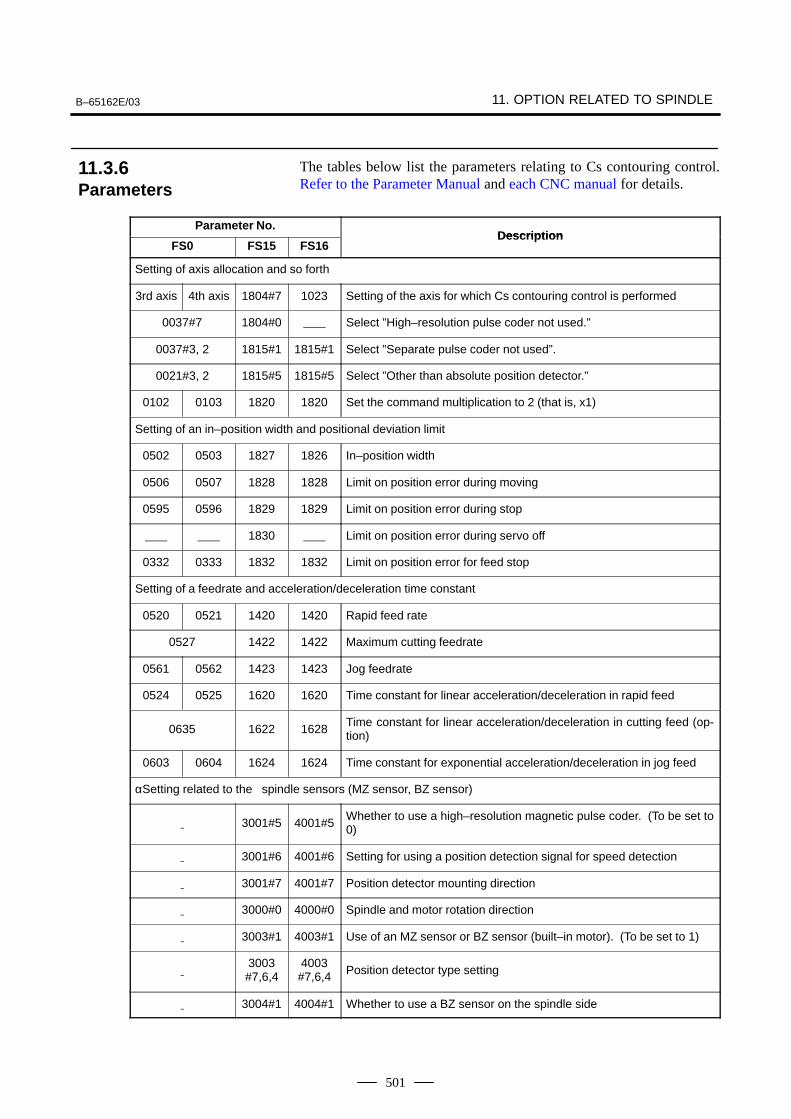
B–65162E/03 11. OPTION RELATED TO SPINDLE
501
The tables below list the parameters relating to Cs contouring control.Refer to the Parameter Manual and each CNC manual for details.
Parameter No.Description
FS0 FS15 FS16Description
Setting of axis allocation and so forth
3rd axis 4th axis 1804#7 1023 Setting of the axis for which Cs contouring control is performed
0037#7 1804#0 Select ”High–resolution pulse coder not used.”
0037#3, 2 1815#1 1815#1 Select ”Separate pulse coder not used”.
0021#3, 2 1815#5 1815#5 Select ”Other than absolute position detector.”
0102 0103 1820 1820 Set the command multiplication to 2 (that is, x1)
Setting of an in–position width and positional deviation limit
0502 0503 1827 1826 In–position width
0506 0507 1828 1828 Limit on position error during moving
0595 0596 1829 1829 Limit on position error during stop
1830 Limit on position error during servo off
0332 0333 1832 1832 Limit on position error for feed stop
Setting of a feedrate and acceleration/deceleration time constant
0520 0521 1420 1420 Rapid feed rate
0527 1422 1422 Maximum cutting feedrate
0561 0562 1423 1423 Jog feedrate
0524 0525 1620 1620 Time constant for linear acceleration/deceleration in rapid feed
0635 1622 1628Time constant for linear acceleration/deceleration in cutting feed (op-tion)
0603 0604 1624 1624 Time constant for exponential acceleration/deceleration in jog feed
αSetting related to the spindle sensors (MZ sensor, BZ sensor)
3001#5 4001#5Whether to use a high–resolution magnetic pulse coder. (To be set to0)
3001#6 4001#6 Setting for using a position detection signal for speed detection
3001#7 4001#7 Position detector mounting direction
3000#0 4000#0 Spindle and motor rotation direction
3003#1 4003#1 Use of an MZ sensor or BZ sensor (built–in motor). (To be set to 1)
3003#7,6,4
4003#7,6,4 Position detector type setting
3004#1 4004#1 Whether to use a BZ sensor on the spindle side
11.3.6Parameters
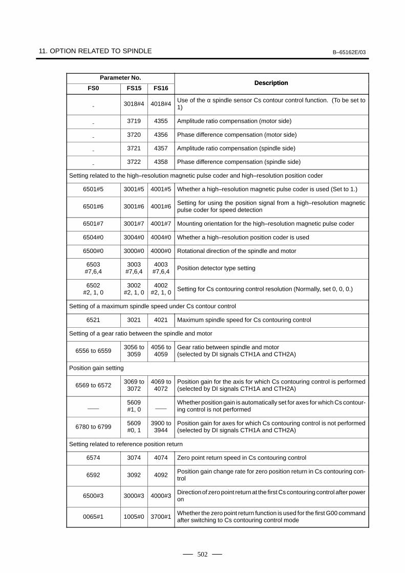
11. OPTION RELATED TO SPINDLE B–65162E/03
502
Parameter No.Description
FS0Description
FS16FS15
3018#4 4018#4Use of the α spindle sensor Cs contour control function. (To be set to1)
3719 4355 Amplitude ratio compensation (motor side)
3720 4356 Phase difference compensation (motor side)
3721 4357 Amplitude ratio compensation (spindle side)
3722 4358 Phase difference compensation (spindle side)
Setting related to the high–resolution magnetic pulse coder and high–resolution position coder
6501#5 3001#5 4001#5 Whether a high–resolution magnetic pulse coder is used (Set to 1.)
6501#6 3001#6 4001#6Setting for using the position signal from a high–resolution magneticpulse coder for speed detection
6501#7 3001#7 4001#7 Mounting orientation for the high–resolution magnetic pulse coder
6504#0 3004#0 4004#0 Whether a high–resolution position coder is used
6500#0 3000#0 4000#0 Rotational direction of the spindle and motor
6503#7,6,4
3003#7,6,4
4003#7,6,4 Position detector type setting
6502#2, 1, 0
3002#2, 1, 0
4002#2, 1, 0 Setting for Cs contouring control resolution (Normally, set 0, 0, 0.)
Setting of a maximum spindle speed under Cs contour control
6521 3021 4021 Maximum spindle speed for Cs contouring control
Setting of a gear ratio between the spindle and motor
6556 to 65593056 to3059
4056 to4059
Gear ratio between spindle and motor(selected by DI signals CTH1A and CTH2A)
Position gain setting
6569 to 65723069 to3072
4069 to4072
Position gain for the axis for which Cs contouring control is performed(selected by DI signals CTH1A and CTH2A)
5609#1, 0
Whether position gain is automatically set for axes for which Cs contour-ing control is not performed
6780 to 67995609#0, 1
3900 to3944
Position gain for axes for which Cs contouring control is not performed(selected by DI signals CTH1A and CTH2A)
Setting related to reference position return
6574 3074 4074 Zero point return speed in Cs contouring control
6592 3092 4092Position gain change rate for zero position return in Cs contouring con-trol
6500#3 3000#3 4000#3Direction of zero point return at the first Cs contouring control after poweron
0065#1 1005#0 3700#1Whether the zero point return function is used for the first G00 commandafter switching to Cs contouring control mode
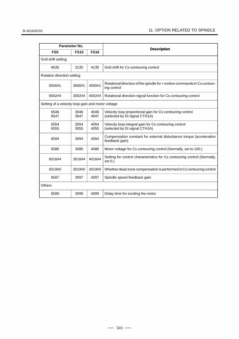
B–65162E/03 11. OPTION RELATED TO SPINDLE
503
Parameter No.Description
FS0Description
FS16FS15
Grid shift setting
6635 3135 4135 Grid shift for Cs contouring control
Rotation direction setting
6500#1 3000#1 4000#1Rotational direction of the spindle for + motion commands in Cs contour-ing control
6502#4 3002#4 4002#4 Rotational direction signal function for Cs contouring control
Setting of a velocity loop gain and motor voltage
65466547
30463047
40464047
Velocity loop proportional gain for Cs contouring control(selected by DI signal CTH1A)
65546555
30543055
40544055
Velocity loop integral gain for Cs contouring control(selected by DI signal CTH1A)
6594 3094 4094Compensation constant for external disturbance torque (accelerationfeedback gain)
6586 3086 4086 Motor voltage for Cs contouring control (Normally, set to 100.)
6516#4 3016#4 4016#4Setting for control characteristics for Cs contouring control (Normally,set 0.)
6519#0 3019#0 4019#0 Whether dead zone compensation is performed in Cs contouring control
6597 3097 4097 Spindle speed feedback gain
Others
6599 3099 4099 Delay time for exciting the motor
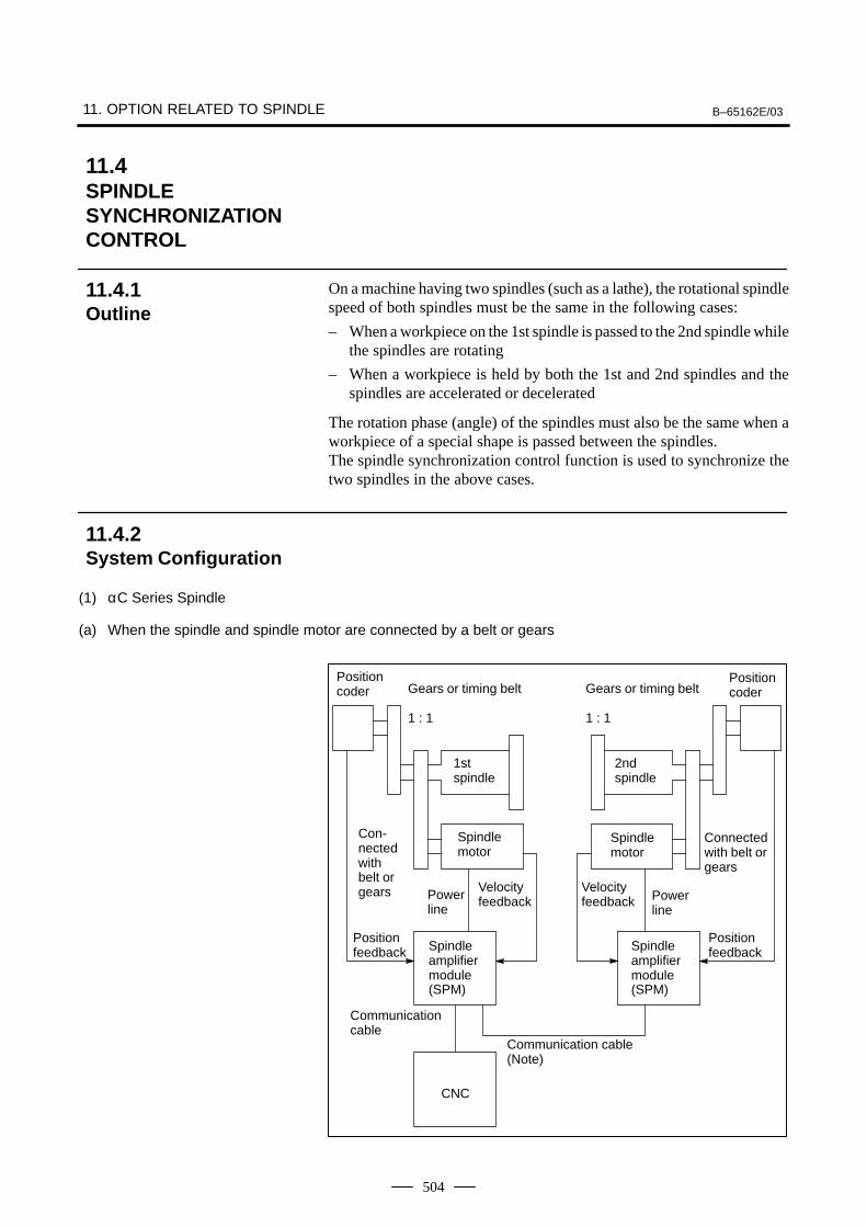
11. OPTION RELATED TO SPINDLE B–65162E/03
504
On a machine having two spindles (such as a lathe), the rotational spindlespeed of both spindles must be the same in the following cases:
– When a workpiece on the 1st spindle is passed to the 2nd spindle whilethe spindles are rotating
– When a workpiece is held by both the 1st and 2nd spindles and thespindles are accelerated or decelerated
The rotation phase (angle) of the spindles must also be the same when aworkpiece of a special shape is passed between the spindles.The spindle synchronization control function is used to synchronize thetwo spindles in the above cases.
(1) αC Series Spindle
(a) When the spindle and spindle motor are connected by a belt or gears
Positioncoder Gears or timing belt
1 : 1
1st spindle
2ndspindle
Con-nectedwithbelt orgears
Spindlemotor
Powerline
Velocityfeedback
Spindleamplifiermodule(SPM)
Communication cable
Communication cable(Note)
CNC
Gears or timing belt
1 : 1
Spindlemotor
Powerline
Velocityfeedback
Spindleamplifiermodule(SPM)
Positioncoder
Positionfeedback
Positionfeedback
Connectedwith belt orgears
11.4SPINDLESYNCHRONIZATIONCONTROL
11.4.1Outline
11.4.2System Configuration
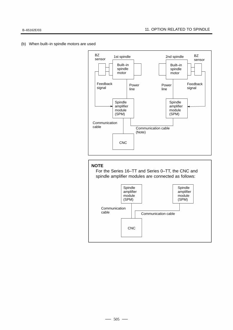
B–65162E/03 11. OPTION RELATED TO SPINDLE
505
(b) When built–in spindle motors are used
CNC
1st spindle 2nd spindle
Communication cable Communication cable
(Note)
Powerline
Spindleamplifiermodule(SPM)
Powerline
BZ sensor
Built–inspindlemotor
Feedbacksignal
Feedbacksignal
Built–inspindlemotor
Spindleamplifiermodule(SPM)
BZ sensor
NOTEFor the Series 16–TT and Series 0–TT, the CNC andspindle amplifier modules are connected as follows:
CNC
Communication cable Communication cable
Spindleamplifiermodule(SPM)
Spindleamplifiermodule(SPM)
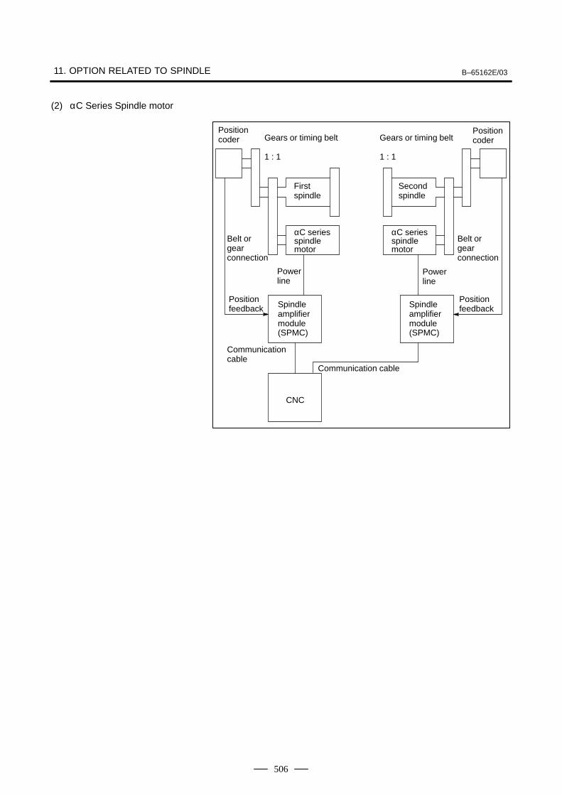
11. OPTION RELATED TO SPINDLE B–65162E/03
506
(2) αC Series Spindle motor
Positioncoder Gears or timing belt
1 : 1
First spindle
Secondspindle
Belt orgear connection
αC seriesspindle motor
Powerline
Spindleamplifiermodule(SPMC)
Communication cable
Communication cable
CNC
Gears or timing belt
1 : 1
Powerline
Spindleamplifiermodule(SPMC)
Positioncoder
Positionfeedback
Positionfeedback
αC seriesspindle motor
Belt orgear connection
B–65162E/03 11. OPTION RELATED TO SPINDLE
507
When the command for spindle synchronization control is issuedwhile the two spindles are rotating at different speeds or stopped, eachspindle increases or decreases its speed to the specified speed. The twospindles are then controlled in synchronization.
If the synchronization speed is changed after the synchronizationcontrol of the two spindles is started, the spindles increase or decreasetheir speed to the new speed. The spindles are synchronized during theacceleration or deceleration as the speed is increased or decreasedaccording to the time constant specified in the parameter. When thespecified synchronization speed is 0 min–1, the two spindles stop at thesame time.
When the command for spindle synchronization control is issued withthe synchronization speed specified as 0 min–1 when both spindles arestopped, the spindles rotate two or three times. After detecting the onerotation signal of the position coder (required for synchronizationcontrol of spindle phase), the spindles stop and enter thesynchronization control state. If the synchronization speed is changedafter the synchronous control state is established, the spindles increaseor decrease their speed to the new speed. The spindles aresynchronized during acceleration or deceleration as the speed isincreased or decreased according to the time constant specified in theparameter.
To handle a workpiece with a unique shape, the spindles need to rotateto keep the phases (angles) of rotation synchronous. When thecommand for spindle phase synchronization is issued when thespindles are already rotating in synchronization, each spindle isadjusted to the rotation phase specified in the parameter. At this time,the speed changes for a moment. Then the two spindles return to thesynchronization control state. Rotation phase synchronization can beestablished by setting the parameters in advance so that the referencepoints of the two spindles match with each other.
When the command for spindle phase synchronization is issued whenthe spindles are controlled in synchronization at 0 min–1, each spindleis rotated and adjusted to the phase specified in the parameter thenstops. It is similar to when the spindles are positioned in the stop state(spindle orientation). This causes the reference points of the spindlesto match with each other (phase synchronization). If thesynchronization speed is changed after a workpiece with a uniqueshape is held with the two spindles, the spindles increase or decreasetheir speed to the new speed. The spindles are synchronized duringacceleration or deceleration as the speed is increased or decreasedaccording to the time constant specified in the parameter.
Constant surface speed control can be executed while a workpiece isbeing held with the two spindles in the synchronous control state.However, the time constant specified in the parameter is not exceededeven when a command for a larger increment or decrement in speedis specified.
Do not switch the rotation direction command (SFR/SRV) duringsynchronization control.
11.4.3Explanation of SpindleSynchronizationControl
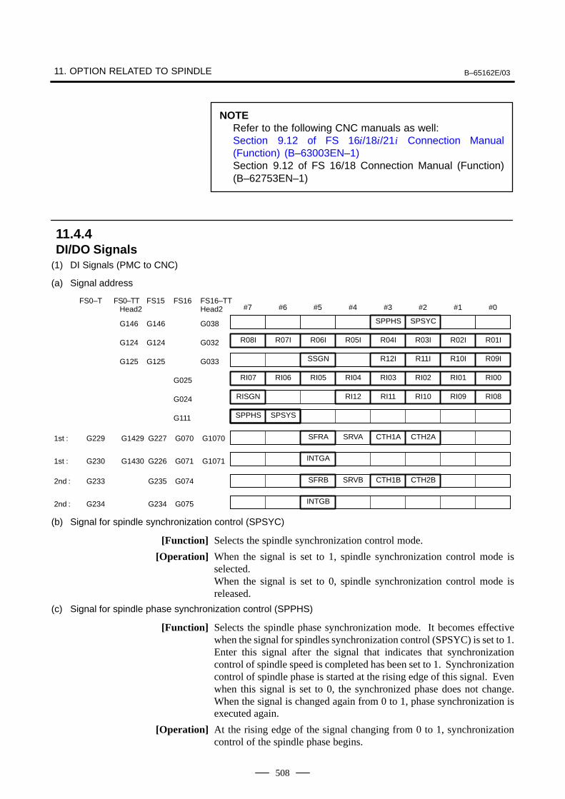
11. OPTION RELATED TO SPINDLE B–65162E/03
508
NOTERefer to the following CNC manuals as well:Section 9.12 of FS 16/18/21i Connection Manual(Function) (B–63003EN–1)Section 9.12 of FS 16/18 Connection Manual (Function)(B–62753EN–1)
(1) DI Signals (PMC to CNC)
(a) Signal address
#7 #6 #5 #4 #3
SPPHS
#2
SPSYC
#1 #0
G146 G146 G038
FS0–T FS0–TT FS15 FS16 FS16–TTHead2 Head2
R08I R07I R06I R05I R04I R03I R02I R01IG124 G124 G032
SSGN R12I R11I R10I R09IG125 G125 G033
RI07 RI06 RI05 RI04 RI03 RI02 RI01 RI00G025
RISGN RI12 RI11 RI10 RI09 RI08G024
SPPHS SPSYSG111
SFRA SRVA CTH1A CTH2A1st : G229 G1429 G227 G070 G1070
INTGA
SFRB SRVB CTH1B CTH2B
INTGB
1st : G230 G1430 G226 G071 G1071
2nd : G233 G235 G074
2nd : G234 G234 G075
(b) Signal for spindle synchronization control (SPSYC)
[Function] Selects the spindle synchronization control mode.
[Operation] When the signal is set to 1, spindle synchronization control mode isselected.When the signal is set to 0, spindle synchronization control mode isreleased.
(c) Signal for spindle phase synchronization control (SPPHS)
[Function] Selects the spindle phase synchronization mode. It becomes effectivewhen the signal for spindles synchronization control (SPSYC) is set to 1.Enter this signal after the signal that indicates that synchronizationcontrol of spindle speed is completed has been set to 1. Synchronizationcontrol of spindle phase is started at the rising edge of this signal. Evenwhen this signal is set to 0, the synchronized phase does not change.When the signal is changed again from 0 to 1, phase synchronization isexecuted again.
[Operation] At the rising edge of the signal changing from 0 to 1, synchronizationcontrol of the spindle phase begins.
11.4.4DI/DO Signals
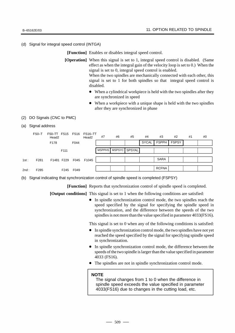
B–65162E/03 11. OPTION RELATED TO SPINDLE
509
(d) Signal for integral speed control (INTGA)
[Function] Enables or disables integral speed control.
[Operation] When this signal is set to 1, integral speed control is disabled. (Sameeffect as when the integral gain of the velocity loop is set to 0.) When thesignal is set to 0, integral speed control is enabled.When the two spindles are mechanically connected with each other, thissignal is set to 1 for both spindles so that integral speed control isdisabled.
When a cylindrical workpiece is held with the two spindles after theyare synchronized in speed
When a workpiece with a unique shape is held with the two spindlesafter they are synchronized in phase
(2) DO Signals (CNC to PMC)
(a) Signal address
#7 #6 #5 #4 #3 #2 #1 #0
F178 F044
FS0–T FS0–TT FS15 FS16 FS16–TTHead2 Head2
F111
1st : F281 F1481 F229 F045 F1045
2nd : F285 F245 F049
SYCAL FSPPH FSPSY
MSPPHS MSPSYC SPSYAL
SARA
RCFNA
(b) Signal indicating that synchronization control of spindle speed is completed (FSPSY)
[Function] Reports that synchronization control of spindle speed is completed.
[Output conditions] This signal is set to 1 when the following conditions are satisfied:
In spindle synchronization control mode, the two spindles reach thespeed specified by the signal for specifying the spindle speed insynchronization, and the difference between the speeds of the twospindles is not more than the value specified in parameter 4033(FS16).
This signal is set to 0 when any of the following conditions is satisfied:
In spindle synchronization control mode, the two spindles have not yetreached the speed specified by the signal for specifying spindle speedin synchronization.
In spindle synchronization control mode, the difference between thespeeds of the two spindle is larger than the value specified in parameter4033 (FS16).
The spindles are not in spindle synchronization control mode.
NOTEThe signal changes from 1 to 0 when the difference inspindle speed exceeds the value specified in parameter4033(FS16) due to changes in the cutting load, etc.
11. OPTION RELATED TO SPINDLE B–65162E/03
510
(c) Signal indicating that synchronization control of spindle phase is completed (FSPPH)
[Function] Reports that synchronization control of spindle phase (control of phasedifference) is completed.
[Output conditions] This signal is set to 1 when the following conditions are satisfied:
In spindle synchronization control mode, the two spindles reach thespeed specified by the signal for specifying the spindle speed insynchronization, and the spindles are synchronized in phase by thesignal for spindle phase synchronization. (The difference between theerror pulses of the two spindles is not greater than the value set inparameter 4810(FS16).)
This signal is set to 0 when any of the following conditions is satisfied:
In spindle synchronization control mode, the two spindles have not yetbeen synchronized in phase.
In spindle synchronization control mode, the difference between theerror pulses of the two spindles is larger than the value specified inparameter 4810 (FS16).
The spindles are not in spindle phase synchronization control mode.
NOTEThe signal changes from 1 to 0 when the difference in theerror pulses exceeds the value specified in parameter4810(FS16) due to changes in the cutting load, etc.
(d) Signal for issuing an alarm detected in spindle synchronization control (SYCAL)
[Function] Reports that the difference between the error pulses of the two spindlesexceeds the value specified in the parameter for spindle synchronizationcontrol mode. This signal is used for error handling in spindlesynchronization control.
[Output conditions] The signal is set to 1 when the following conditions are satisfied:
In spindle synchronization control mode, the difference between theerror pulses of the two spindles exceeds the value specified inparameter 4811(FS16), after spindle synchronization control has beenput in effect.
The signal is set to 0 when any of the following conditions is satisfied:
The spindles are not in spindle synchronization control mode.
In spindle synchronization control mode, the difference between theerror pulses of the two spindles is not greater than the value specifiedin parameter 4811(FS16).
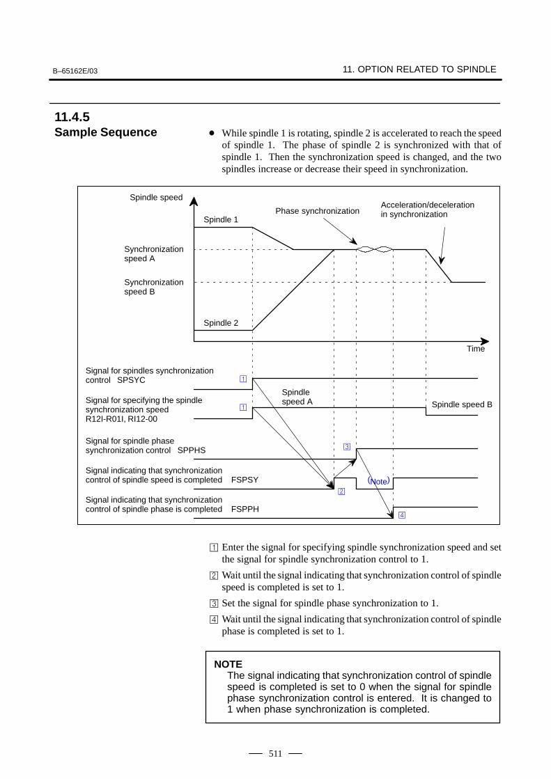
B–65162E/03 11. OPTION RELATED TO SPINDLE
511
While spindle 1 is rotating, spindle 2 is accelerated to reach the speedof spindle 1. The phase of spindle 2 is synchronized with that ofspindle 1. Then the synchronization speed is changed, and the twospindles increase or decrease their speed in synchronization.
(Note)
Spindle speed B
Spindlespeed A
Signal indicating that synchronization control of spindle speed is completed FSPSY
Signal for spindle phase synchronization control SPPHS
Signal for specifying the spindlesynchronization speedR12I-R01I, RI12-00
Signal for spindles synchronizationcontrol SPSYC
Time
Spindle 2
Spindle 1
Spindle speed
Phase synchronizationAcceleration/deceleration in synchronization
Synchronization speed A
Synchronization speed B
Signal indicating that synchronization control of spindle phase is completed FSPPH
Enter the signal for specifying spindle synchronization speed and setthe signal for spindle synchronization control to 1.
Wait until the signal indicating that synchronization control of spindlespeed is completed is set to 1.
Set the signal for spindle phase synchronization to 1.
Wait until the signal indicating that synchronization control of spindlephase is completed is set to 1.
NOTEThe signal indicating that synchronization control of spindlespeed is completed is set to 0 when the signal for spindlephase synchronization control is entered. It is changed to1 when phase synchronization is completed.
11.4.5Sample Sequence
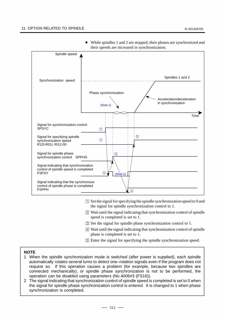
11. OPTION RELATED TO SPINDLE B–65162E/03
512
While spindles 1 and 2 are stopped, their phases are synchronized andtheir speeds are increased in synchronization.
Signal indicating that synchronization control of spindle speed is completedFSPSY
Signal for spindle phase synchronization control SPPHS
Signal for specifying spindle synchronization speedR12I-R01I, RI12-00
Signal for synchronization controlSPSYC
Time
Spindles 1 and 2
Spindle speed
Phase synchronization
Acceleration/deceleration in synchronization
Synchronization speed
Signal indicating that the synchronous control of spindle phase is completedFSPPH
(Note 1)
(Note 2)
Set the signal for specifying the spindle synchronization speed to 0 andthe signal for spindle synchronization control to 1.
Wait until the signal indicating that synchronization control of spindlespeed is completed is set to 1.
Set the signal for spindle phase synchronization control to 1.
Wait until the signal indicating that synchronization control of spindlephase is completed is set to 1.
Enter the signal for specifying the spindle synchronization speed.
NOTE1 When the spindle synchronization mode is switched (after power is supplied), each spindle
automatically rotates several turns to detect one–rotation signals even if the program does notrequest so. If this operation causes a problem (for example, because two spindles areconnected mechanically), or spindle phase synchronization is not to be performed, theoperation can be disabled using parameters (No.4006#3 (FS16)).
2 The signal indicating that synchronization control of spindle speed is completed is set to 0 whenthe signal for spindle phase synchronization control is entered. It is changed to 1 when phasesynchronization is completed.
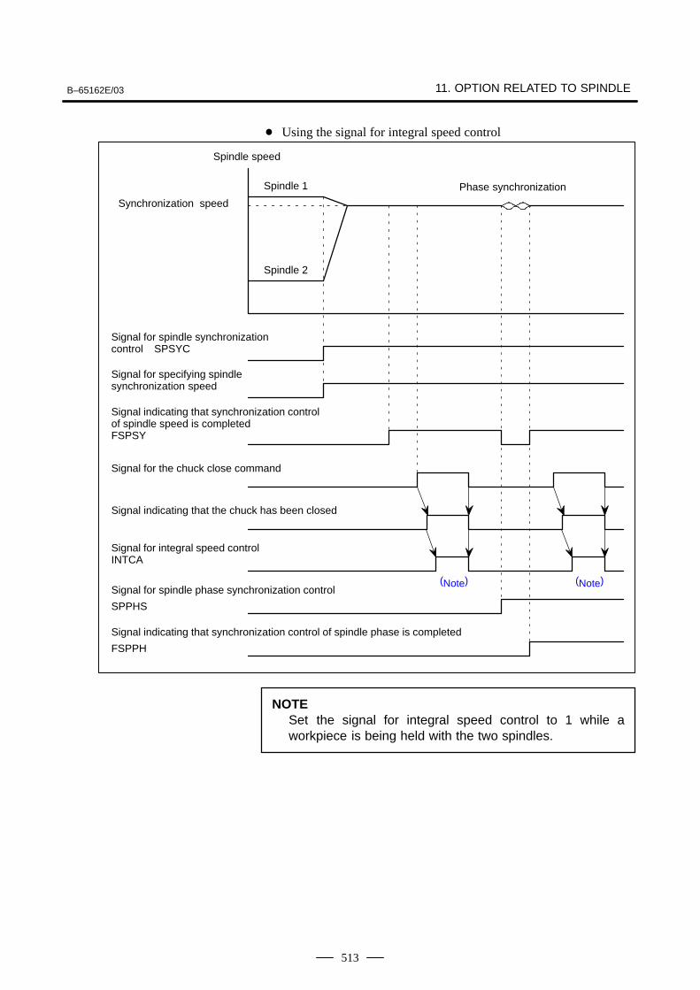
B–65162E/03 11. OPTION RELATED TO SPINDLE
513
Using the signal for integral speed control
Phase synchronization
Spindle 2
Signal indicating that synchronization control of spindle phase is completed
FSPPH
Signal for spindle phase synchronization control
SPPHS
Signal indicating that synchronization control of spindle speed is completedFSPSY
Signal for the chuck close command
Signal for specifying spindle synchronization speed
Signal for spindle synchronizationcontrol SPSYC
(Note)
Spindle speed
Synchronization speed
Signal for integral speed controlINTCA
Spindle 1
Signal indicating that the chuck has been closed
(Note)
NOTESet the signal for integral speed control to 1 while aworkpiece is being held with the two spindles.
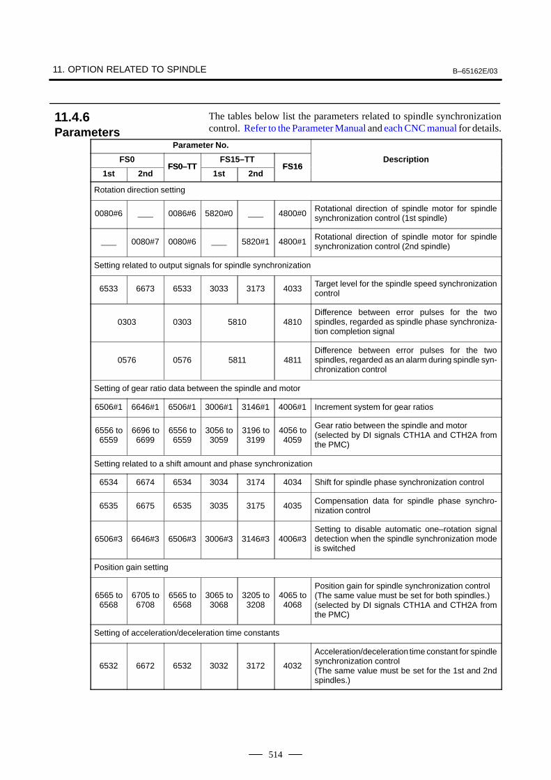
11. OPTION RELATED TO SPINDLE B–65162E/03
514
The tables below list the parameters related to spindle synchronizationcontrol. Refer to the Parameter Manual and each CNC manual for details.
Parameter No.
FS0FS0–TT
FS15–TTFS16
Description
1st 2ndFS0–TT
1st 2ndFS16
Rotation direction setting
0080#6 0086#6 5820#0 4800#0Rotational direction of spindle motor for spindlesynchronization control (1st spindle)
0080#7 0080#6 5820#1 4800#1Rotational direction of spindle motor for spindlesynchronization control (2nd spindle)
Setting related to output signals for spindle synchronization
6533 6673 6533 3033 3173 4033Target level for the spindle speed synchronizationcontrol
0303 0303 5810 4810Difference between error pulses for the twospindles, regarded as spindle phase synchroniza-tion completion signal
0576 0576 5811 4811Difference between error pulses for the twospindles, regarded as an alarm during spindle syn-chronization control
Setting of gear ratio data between the spindle and motor
6506#1 6646#1 6506#1 3006#1 3146#1 4006#1 Increment system for gear ratios
6556 to6559
6696 to6699
6556 to6559
3056 to3059
3196 to3199
4056 to4059
Gear ratio between the spindle and motor(selected by DI signals CTH1A and CTH2A fromthe PMC)
Setting related to a shift amount and phase synchronization
6534 6674 6534 3034 3174 4034 Shift for spindle phase synchronization control
6535 6675 6535 3035 3175 4035Compensation data for spindle phase synchro-nization control
6506#3 6646#3 6506#3 3006#3 3146#3 4006#3Setting to disable automatic one–rotation signaldetection when the spindle synchronization modeis switched
Position gain setting
6565 to6568
6705 to6708
6565 to6568
3065 to3068
3205 to3208
4065 to4068
Position gain for spindle synchronization control(The same value must be set for both spindles.)(selected by DI signals CTH1A and CTH2A fromthe PMC)
Setting of acceleration/deceleration time constants
6532 6672 6532 3032 3172 4032
Acceleration/deceleration time constant for spindlesynchronization control (The same value must be set for the 1st and 2ndspindles.)
11.4.6Parameters
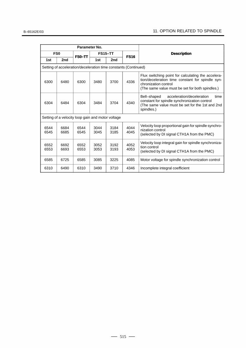
B–65162E/03 11. OPTION RELATED TO SPINDLE
515
Parameter No.
DescriptionFS0 DescriptionFS16
FS15–TTFS0–TT
1st
DescriptionFS16
2nd1stFS0–TT
2nd
Setting of acceleration/deceleration time constants (Continued)
6300 6480 6300 3480 3700 4336
Flux switching point for calculating the accelera-tion/deceleration time constant for spindle syn-chronization control(The same value must be set for both spindles.)
6304 6484 6304 3484 3704 4340
Bell–shaped acceleration/deceleration timeconstant for spindle synchronization control(The same value must be set for the 1st and 2ndspindles.)
Setting of a velocity loop gain and motor voltage
65446545
66846685
65446545
30443045
31843185
40444045
Velocity loop proportional gain for spindle synchro-nization control(selected by DI signal CTH1A from the PMC)
65526553
66926693
65526553
30523053
31923193
40524053
Velocity loop integral gain for spindle synchroniza-tion control(selected by DI signal CTH1A from the PMC)
6585 6725 6585 3085 3225 4085 Motor voltage for spindle synchronization control
6310 6490 6310 3490 3710 4346 Incomplete integral coefficient
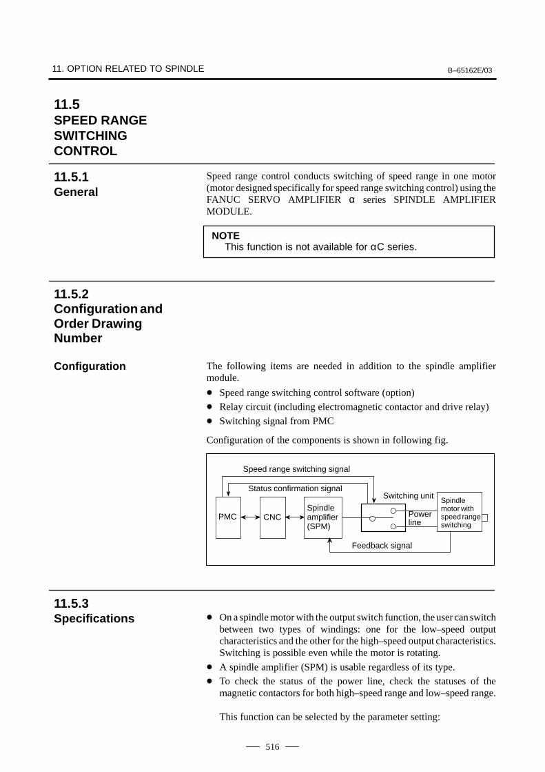
11. OPTION RELATED TO SPINDLE B–65162E/03
516
Speed range control conducts switching of speed range in one motor(motor designed specifically for speed range switching control) using theFANUC SERVO AMPLIFIER α series SPINDLE AMPLIFIERMODULE.
NOTEThis function is not available for αC series.
The following items are needed in addition to the spindle amplifiermodule.
Speed range switching control software (option)
Relay circuit (including electromagnetic contactor and drive relay)
Switching signal from PMC
Configuration of the components is shown in following fig.
Status confirmation signalSwitching unit
Spindleamplifier(SPM)
Power line
Spindle motor withspeed rangeswitching
PMC CNC
Feedback signal
Speed range switching signal
On a spindle motor with the output switch function, the user can switchbetween two types of windings: one for the low–speed outputcharacteristics and the other for the high–speed output characteristics.Switching is possible even while the motor is rotating.
A spindle amplifier (SPM) is usable regardless of its type.
To check the status of the power line, check the statuses of themagnetic contactors for both high–speed range and low–speed range.
This function can be selected by the parameter setting:
11.5SPEED RANGE SWITCHINGCONTROL
11.5.1General
11.5.2Configuration andOrder DrawingNumber
Configuration
11.5.3Specifications
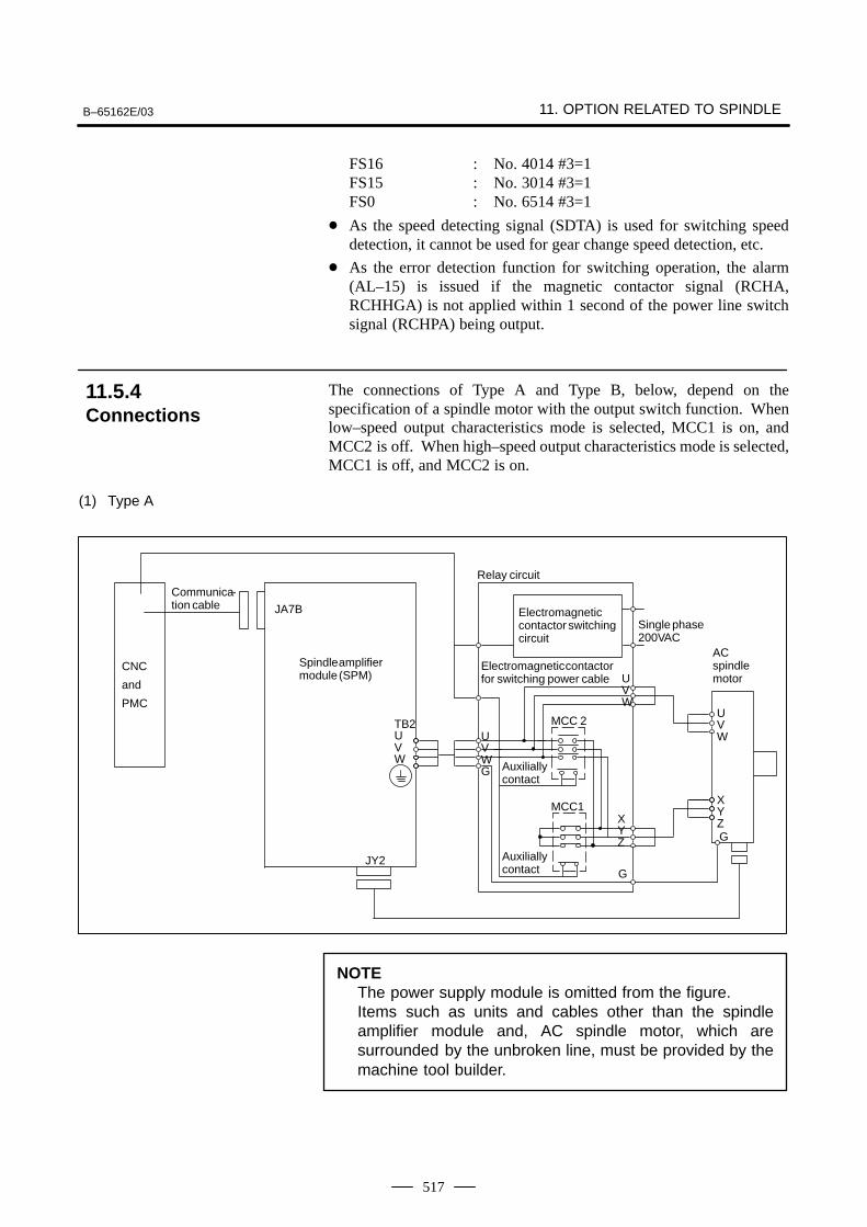
B–65162E/03 11. OPTION RELATED TO SPINDLE
517
FS16 : No. 4014 #3=1FS15 : No. 3014 #3=1FS0 : No. 6514 #3=1
As the speed detecting signal (SDTA) is used for switching speeddetection, it cannot be used for gear change speed detection, etc.
As the error detection function for switching operation, the alarm(AL–15) is issued if the magnetic contactor signal (RCHA,RCHHGA) is not applied within 1 second of the power line switchsignal (RCHPA) being output.
The connections of Type A and Type B, below, depend on thespecification of a spindle motor with the output switch function. Whenlow–speed output characteristics mode is selected, MCC1 is on, andMCC2 is off. When high–speed output characteristics mode is selected,MCC1 is off, and MCC2 is on.
(1) Type A
ACspindlemotor
CNC
and
PMC
JY2
JA7B
Spindle amplifiermodule (SPM)
TB2UVW
Electromagneticcontactor switchingcircuit
Single phase200VAC
Relay circuit
Communica-tion cable
G
G
Auxiliallycontact
Electromagnetic contactorfor switching power cable
MCC 2UVWG
UVW
MCC1XYZ
UVW
XYZ
Auxiliallycontact
ÂÂÂÂ
NOTEThe power supply module is omitted from the figure.Items such as units and cables other than the spindleamplifier module and, AC spindle motor, which aresurrounded by the unbroken line, must be provided by themachine tool builder.
11.5.4Connections
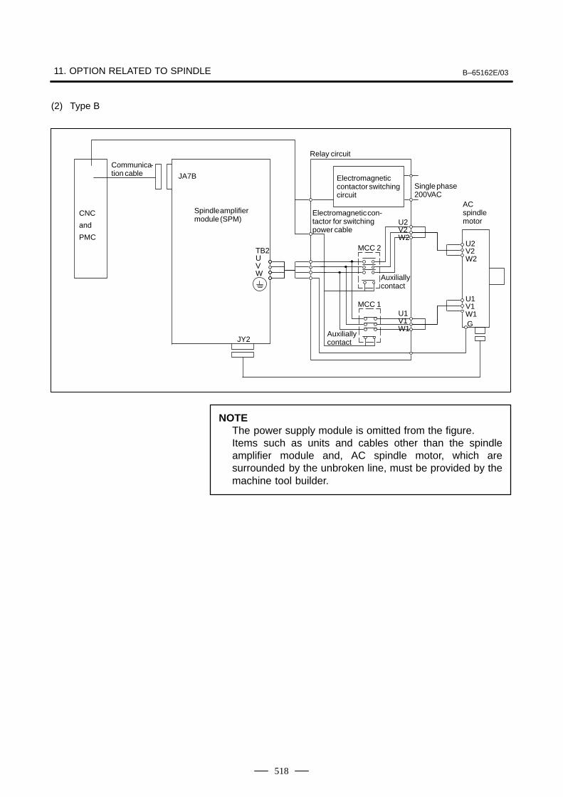
11. OPTION RELATED TO SPINDLE B–65162E/03
518
(2) Type B
ACspindlemotor
CNC
and
PMC
JY2
JA7B
Spindle amplifiermodule (SPM)
TB2UVW
Electromagneticcontactor switchingcircuit
Single phase200VAC
Relay circuit
Communica-tion cable
G
Electromagnetic con-tactor for switchingpower cable
U2V2W2
U1V1W1
U2V2W2
U1V1W1
MCC 2
MCC 1
Auxiliallycontact
Auxiliallycontact
ÂÂÂÂ
NOTEThe power supply module is omitted from the figure.Items such as units and cables other than the spindleamplifier module and, AC spindle motor, which aresurrounded by the unbroken line, must be provided by themachine tool builder.
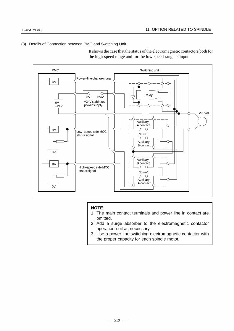
B–65162E/03 11. OPTION RELATED TO SPINDLE
519
(3) Details of Connection between PMC and Switching Unit
It shows the case that the status of the electromagnetic contactors both forthe high-speed range and for the low-speed range is input.
Auxiliary A contact
MCC1
Auxiliary B contact
Auxiliary B contact
MCC2
Auxiliary A contact
Relay
Switching unit
200VAC
Power–line change signal
+24V stabirizedpower supply
0V +24V
Low–speed side MCCstatus signal
High–speed side MCCstatus signal
0V+24V
0V
RV
0V
RV
DV
PMC
NOTE1 The main contact terminals and power line in contact are
omitted.2 Add a surge absorber to the electromagnetic contactor
operation coil as necessary.3 Use a power-line switching electromagnetic contactor with
the proper capacity for each spindle motor.
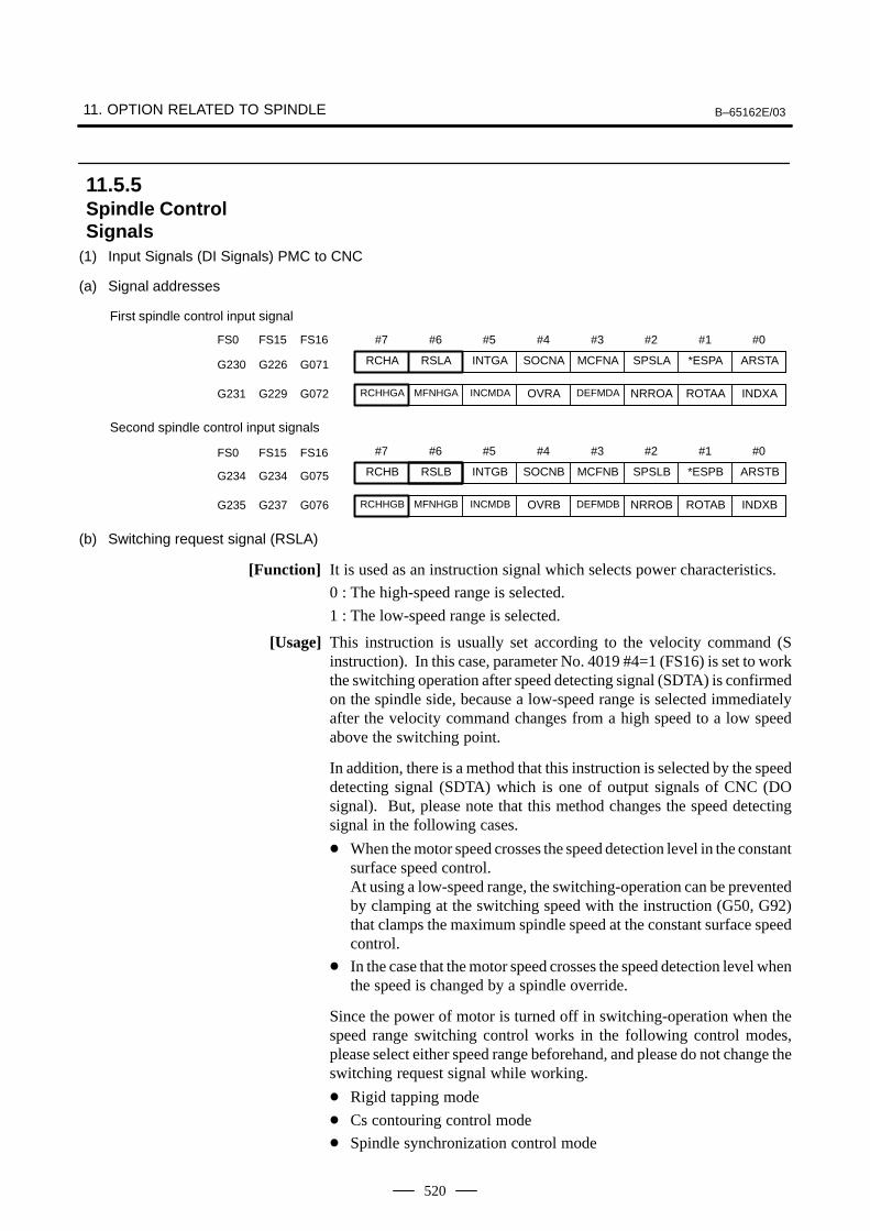
11. OPTION RELATED TO SPINDLE B–65162E/03
520
(1) Input Signals (DI Signals) PMC to CNC
(a) Signal addresses
#7 #6 #5 #4 #3 #2 #1 #0
First spindle control input signal
RCHA RSLA INTGA SOCNA MCFNA SPSLA *ESPA ARSTAG230 G226 G071
RCHHGA MFNHGA INCMDA OVRA DEFMDA NRROA ROTAA INDXAG231 G229 G072
FS0 FS15 FS16
#7 #6 #5 #4 #3 #2 #1 #0FS0 FS15 FS16
Second spindle control input signals
RCHB RSLB INTGB SOCNB MCFNB SPSLB *ESPB ARSTBG234 G234 G075
RCHHGB MFNHGB INCMDB OVRB DEFMDB NRROB ROTAB INDXBG235 G237 G076
(b) Switching request signal (RSLA)
[Function] It is used as an instruction signal which selects power characteristics.
0 : The high-speed range is selected.
1 : The low-speed range is selected.
[Usage] This instruction is usually set according to the velocity command (Sinstruction). In this case, parameter No. 4019 #4=1 (FS16) is set to workthe switching operation after speed detecting signal (SDTA) is confirmedon the spindle side, because a low-speed range is selected immediatelyafter the velocity command changes from a high speed to a low speedabove the switching point.
In addition, there is a method that this instruction is selected by the speeddetecting signal (SDTA) which is one of output signals of CNC (DOsignal). But, please note that this method changes the speed detectingsignal in the following cases.
When the motor speed crosses the speed detection level in the constantsurface speed control.At using a low-speed range, the switching-operation can be preventedby clamping at the switching speed with the instruction (G50, G92)that clamps the maximum spindle speed at the constant surface speedcontrol.
In the case that the motor speed crosses the speed detection level whenthe speed is changed by a spindle override.
Since the power of motor is turned off in switching-operation when thespeed range switching control works in the following control modes,please select either speed range beforehand, and please do not change theswitching request signal while working.
Rigid tapping mode
Cs contouring control mode
Spindle synchronization control mode
11.5.5Spindle ControlSignals
B–65162E/03 11. OPTION RELATED TO SPINDLE
521
Spindle indexing mode
The spindle orientation is completed.
(c) Electromagnetic contactor for the speed range switching status signal (RCHA)
[Function] The opening and closing status signal of the electromagnetic contactor fora low-speed range of the spindle motor is input.
0 : The low-speed range side electromagnetic contactor is open.
1 : The low-speed range side electromagnetic contactor is closed.
[Usage] The status of the auxiliary contact (”A” contact) of electromagneticcontactor for a low-speed is usually input.The status of the low-speed range side electromagnetic contactor is inputas this signal for parameter NO. 4014 #3=1 (FS16).
[Function] The selection status signal of the electromagnetic contactor for the sppedrange switching of the spindle motor is inputted.
0 : The high-speed range is selected.
1 : The low-speed range is selected.
[Usage] When the electromagnetic contactor changes from the low-speed side tothe high-speed side, this signal is set from ”1” to ”0” after it is confirmedthat the electromagnetic contactor on the low-speed side is off and that theelectromagnetic contactor on the high-speed side is on.When the electromagnetic contactor changes from the high-speed side tothe low-speed side, this signal is set from ”0” to”1” after it is confirmedthat the electromagnetic contactor on the high-speed side is off and thatthe electromagnetic contactor on the low-speed side is on.
(d) High-speed range side electromagnetic contactor status signal (RCHHGA)
[Function] The opening and closing status signal of the electromagnetic contactor fora high-speed range of the spindle motor is input.
0 : The high-speed range side electromagnetic contactor is open.
1 : The high-speed range side electromagnetic contactor is closed.
[Usage] The status of the auxiliary contact (”A” contact) of the electromagneticcontactor for a high-speed range is usually input.
This signal is effective for parameter NO. 4014 #3=1 (FS16).
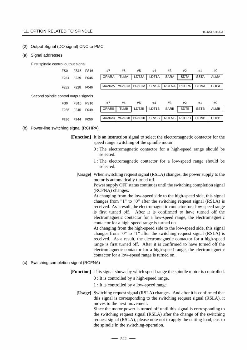
11. OPTION RELATED TO SPINDLE B–65162E/03
522
(2) Output Signal (DO signal) CNC to PMC
(a) Signal addresses
#7 #6 #5 #4 #3 #2 #1 #0
First spindle control output signal
ORARA TLMA LDT2A LDT1A SARA SDTA SSTA ALMAF281 F229 F045
MOAR2A MOAR1A POAR2A SLVSA RCFNA RCHPA CFINA CHPAF282 F228 F046
FS0 FS15 FS16
#7 #6 #5 #4 #3 #2 #1 #0FS0 FS15 FS16
Second spindle control output signals
ORARB TLMB LDT2B LDT1B SARB SDTB SSTB ALMBF285 F245 F049
MOAR2B MOAR1B POAR2B SLVSB RCFNB RCHPB CFINB CHPBF286 F244 F050
(b) Power-line switching signal (RCHPA)
[Function] It is an instruction signal to select the electromagnetic contactor for thespeed range switching of the spindle motor.
0 : The electromagnetic contactor for a high-speed range should beselected.
1 : The electromagnetic contactor for a low-speed range should beselected.
[Usage] When switching request signal (RSLA) changes, the power supply to themotor is automatically turned off.Power supply OFF status continues until the switching completion signal(RCFNA) changes.At changing from the low-speed side to the high-speed side, this signalchanges from ”1” to ”0” after the switching request signal (RSLA) isreceived. As a result, the electromagnetic contactor for a low-speed rangeis first turned off. After it is confirmed to have turned off theelectromagnetic contactor for a low-speed range, the electromagneticcontactor for a high-speed range is turned on.At changing from the high-speed side to the low-speed side, this signalchanges from ”0” to ”1” after the switching request signal (RSLA) isreceived. As a result, the electromagnetic contactor for a high-speedrange is first turned off. After it is confirmed to have turned off theelectromagnetic contactor for a high-speed range, the electromagneticcontactor for a low-speed range is turned on.
(c) Switching completion signal (RCFNA)
[Function] This signal shows by which speed range the spindle motor is controlled.
0 : It is controlled by a high-speed range.
1 : It is controlled by a low-speed range.
[Usage] Switching request signal (RSLA) changes. And after it is confirmed thatthis signal is corresponding to the switching request signal (RSLA), itmoves to the next movement.Since the motor power is turned off until this signal is corresponding tothe switching request signal (RSLA) after the change of the switchingrequest signal (RSLA), please note not to apply the cutting load, etc. tothe spindle in the switching-operation.
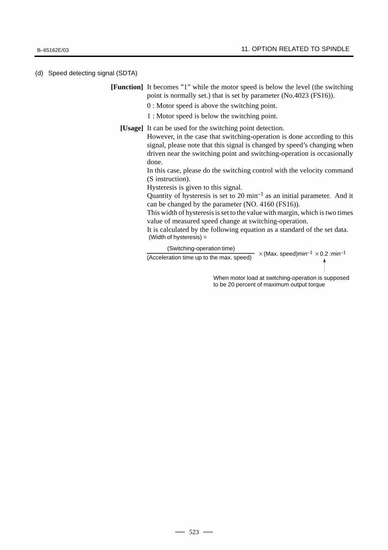
B–65162E/03 11. OPTION RELATED TO SPINDLE
523
(d) Speed detecting signal (SDTA)
[Function] It becomes ”1” while the motor speed is below the level (the switchingpoint is normally set.) that is set by parameter (No.4023 (FS16)).
0 : Motor speed is above the switching point.
1 : Motor speed is below the switching point.
[Usage] It can be used for the switching point detection.However, in the case that switching-operation is done according to thissignal, please note that this signal is changed by speed’s changing whendriven near the switching point and switching-operation is occasionallydone.In this case, please do the switching control with the velocity command(S instruction).Hysteresis is given to this signal.Quantity of hysteresis is set to 20 min–1 as an initial parameter. And itcan be changed by the parameter (NO. 4160 (FS16)).This width of hysteresis is set to the value with margin, which is two timesvalue of measured speed change at switching-operation.It is calculated by the following equation as a standard of the set data.(Width of hysteresis) =
(Switching-operation time)(Max. speed)min–1 0.2 :min–1
(Acceleration time up to the max. speed)
When motor load at switching-operation is supposedto be 20 percent of maximum output torque
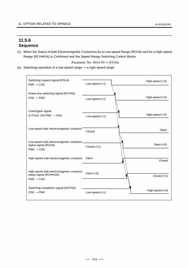
11. OPTION RELATED TO SPINDLE B–65162E/03
524
(1) When the Status of both Electromagnetic Contactors for a Low-speed Range (RCHA) and for a High-speed
Range (RCHHGA) is Confirmed and the Speed Range Switching Control Works
Parameter No. 4014 #3=1 (FS16)
(a) Switching-operation of a low-speed range a high-speed range
Low-speed (=1)Switching request signal (RSLA)
PMC CNC
Power-line switching signal (RCHPA)
CNC PMC
Clutch/gear signal
(CTH1A, 2A) PMC CNC
Low-speed side electromagnetic contactor
Low-speed side electromagnetic contactorstatus signal (RCHA)
PMC CNC
High-speed side electromagnetic contactor
High-speed side electromagnetic contactorstatus signal (RCHHGA)
PMC CNC
Switching completion signal (RCFNA)
CNC PMC
Low-speed (=1)
Closed
Closed (=1)
Open
Open (=0)
Low-speed (=1)
High-speed (=0)
High-speed (=0)
Open
Open (=0)
Closed
Closed (=1)
High-speed (=0)
Low-speed (=1)High-speed (=0)
11.5.6Sequence
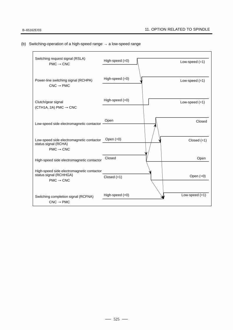
B–65162E/03 11. OPTION RELATED TO SPINDLE
525
(b) Switching-operation of a high-speed range → a low-speed range
High-speed (=0)Switching request signal (RSLA)
PMC CNC
Power-line switching signal (RCHPA)
CNC PMC
Clutch/gear signal
(CTH1A, 2A) PMC CNC
Low-speed side electromagnetic contactor
Low-speed side electromagnetic contactorstatus signal (RCHA)
PMC CNC
High-speed side electromagnetic contactor
High-speed side electromagnetic contactorstatus signal (RCHHGA)
PMC CNC
Switching completion signal (RCFNA)
CNC PMC
High-speed (=0)
Open
Open (=0)
Closed
Closed (=1)
High-speed (=0)
Low-speed (=1)
Low-speed (=1)
Closed
Closed (=1)
Open
Open (=0)
Low-speed (=1)
High-speed (=0)Low-speed (=1)
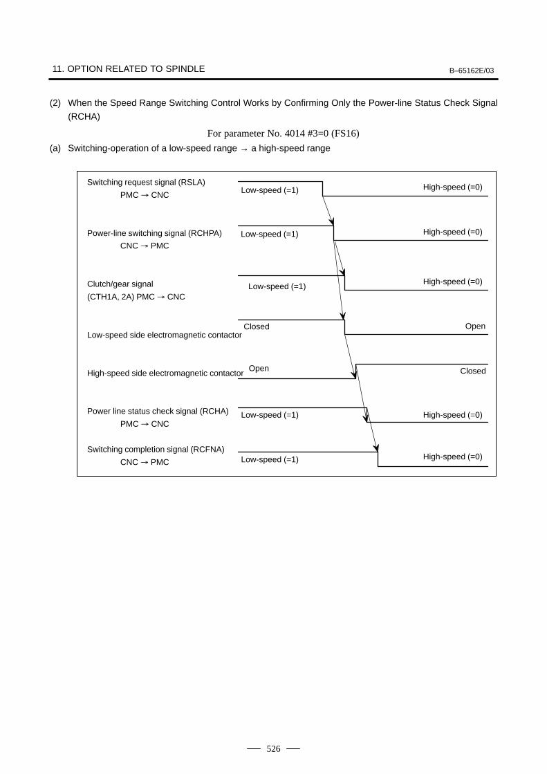
11. OPTION RELATED TO SPINDLE B–65162E/03
526
(2) When the Speed Range Switching Control Works by Confirming Only the Power-line Status Check Signal
(RCHA)
For parameter No. 4014 #3=0 (FS16)
(a) Switching-operation of a low-speed range → a high-speed range
Low-speed (=1)Switching request signal (RSLA)
PMC CNC
Power-line switching signal (RCHPA)
CNC PMC
Clutch/gear signal
(CTH1A, 2A) PMC CNC
Low-speed side electromagnetic contactor
High-speed side electromagnetic contactor
Power line status check signal (RCHA)
PMC CNC
Switching completion signal (RCFNA)
CNC PMC
Low-speed (=1)
Closed
Open
Low-speed (=1)
High-speed (=0)
High-speed (=0)
Open
Closed
High-speed (=0)
Low-speed (=1) High-speed (=0)
Low-speed (=1)High-speed (=0)
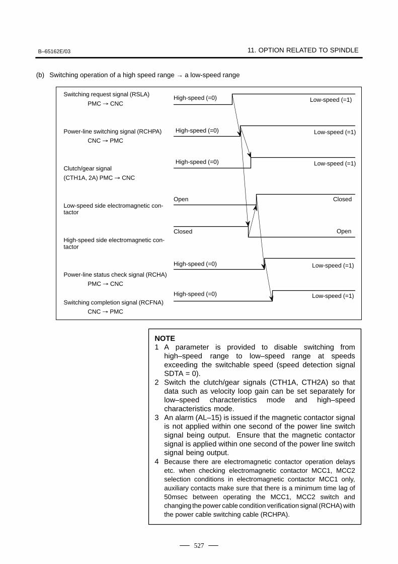
B–65162E/03 11. OPTION RELATED TO SPINDLE
527
(b) Switching operation of a high speed range → a low-speed range
High-speed (=0)Switching request signal (RSLA)
PMC CNC
Power-line switching signal (RCHPA)
CNC PMC
Clutch/gear signal
(CTH1A, 2A) PMC CNC
Low-speed side electromagnetic con-tactor
High-speed side electromagnetic con-tactor
Power-line status check signal (RCHA)
PMC CNC
Switching completion signal (RCFNA)
CNC PMC
High-speed (=0)
Open
Closed
Low-speed (=1)
Low-speed (=1)
Closed
Open
High-speed (=0) Low-speed (=1)
High-speed (=0) Low-speed (=1)
High-speed (=0) Low-speed (=1)
NOTE1 A parameter is provided to disable switching from
high–speed range to low–speed range at speedsexceeding the switchable speed (speed detection signalSDTA = 0).
2 Switch the clutch/gear signals (CTH1A, CTH2A) so thatdata such as velocity loop gain can be set separately forlow–speed characteristics mode and high–speedcharacteristics mode.
3 An alarm (AL–15) is issued if the magnetic contactor signalis not applied within one second of the power line switchsignal being output. Ensure that the magnetic contactorsignal is applied within one second of the power line switchsignal being output.
4 Because there are electromagnetic contactor operation delaysetc. when checking electromagnetic contactor MCC1, MCC2selection conditions in electromagnetic contactor MCC1 only,auxiliary contacts make sure that there is a minimum time lag of50msec between operating the MCC1, MCC2 switch andchanging the power cable condition verification signal (RCHA) withthe power cable switching cable (RCHPA).
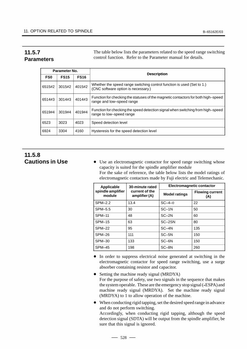
11. OPTION RELATED TO SPINDLE B–65162E/03
528
The table below lists the parameters related to the speed range switchingcontrol function. Refer to the Parameter manual for details.
Parameter No.Description
FS0 FS15 FS16Description
6515#2 3015#2 4015#2Whether the speed range switching control function is used (Set to 1.)(CNC software option is necessary.)
6514#3 3014#3 4014#3Function for checking the statuses of the magnetic contactors for both high–speedrange and low–speed range
6519#4 3019#4 4019#4Function for checking the speed detection signal when switching from high–speedrange to low–speed range
6523 3023 4023 Speed detection level
6924 3304 4160 Hysteresis for the speed detection level
Use an electromagnetic contactor for speed range switching whosecapacity is suited for the spindle amplifier moduleFor the sake of reference, the table below lists the model ratings ofelectromagnetic contactors made by Fuji electric and Telemechanic.
Applicable 30-minute rated Electromagnetic contactorApplicablespindle amplifier
module
30 minute ratedcurrent of theamplifier (A) Model ratings Flowing current
(A)
SPM–2.2 13.4 SC–4–0 22
SPM–5.5 30 SC–1N 50
SPM–11 48 SC–2N 60
SPM–15 63 SC–2SN 80
SPM–22 95 SC–4N 135
SPM–26 111 SC–5N 150
SPM–30 133 SC–6N 150
SPM–45 198 SC–8N 260
In order to suppress electrical noise generated at switching in theelectromagnetic contactor for speed range switching, use a surgeabsorber containing resistor and capacitor.
Setting the machine ready signal (MRDYA)For the purpose of safety, use two signals in the sequence that makesthe system operable. These are the emergency stop signal (*ESPA) andmachine ready signal (MRDYA). Set the machine ready signal(MRDYA) to 1 to allow operation of the machine.
When conducting rigid tapping, set the desired speed range in advanceand do not perform switching.Accordingly, when conducting rigid tapping, although the speeddetection signal (SDTA) will be output from the spindle amplifier, besure that this signal is ignored.
11.5.7Parameters
11.5.8Cautions in Use
B–65162E/03 11. OPTION RELATED TO SPINDLE
529
Speed detection signal (SDTA) and selection signal Two windings are installed within the AC spindle motor. Outputpower characteristics can be changed by switching these twowindings.When conducting this speed range switching (during rotation) and therigid tapping, the control may be limited by only the high-speedwinding.Ensure a sequence in the PMC that allows selection of 2 output powercharacteristics and enables selection of a switching sequence duringrotation.
Use gear/clutch signal CTH1A and CTH2A to be able to set differentvelocity loop gains for low-speed and high-speed.
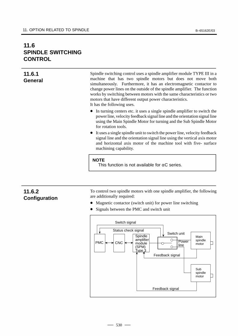
11. OPTION RELATED TO SPINDLE B–65162E/03
530
Spindle switching control uses a spindle amplifier module TYPE III in amachine that has two spindle motors but does not move bothsimultaneously. Furthermore, it has an electromagnetic contactor tochange power lines on the outside of the spindle amplifier. The functionworks by switching between motors with the same characteristics or twomotors that have different output power characteristics.It has the following uses.
In turning centers etc. it uses a single spindle amplifier to switch thepower line, velocity feedback signal line and the orientation signal lineusing the Main Spindle Motor for turning and the Sub Spindle Motorfor rotation tools.
It uses a single spindle unit to switch the power line, velocity feedbacksignal line and the orientation signal line using the vertical axis motorand horizontal axis motor of the machine tool with five- surfacemachining capability.
NOTEThis function is not available for αC series.
To control two spindle motors with one spindle amplifier, the followingare additionally required:
Magnetic contactor (switch unit) for power line switching
Signals between the PMC and switch unit
Switch signal
Status check signalSwitch unit
Spindleamplifiermodule(SPM)Type 3
Power line
Main spindle motorPMC CNC
Feedback signal
Sub spindle motor
Feedback signal
11.6SPINDLE SWITCHINGCONTROL
11.6.1General
11.6.2Configuration
B–65162E/03 11. OPTION RELATED TO SPINDLE
531
By using a spindle amplifier module (SPM) of Type 3, two spindlemotors are driven. The two spindle motors are switched; the twospindle motors cannot be driven at the same time.
A combination of a main spindle motor and sub spindle motor can beselected freely from those spindle motors that can be driven by thespindle amplifier module. From the spindle amplifier modules thatmatch two spindle motors, select that spindle amplifier module thathas the larger capacity. Depending on the combination of spindlemotors and spindle amplifier module, the parameters may have to bemodified.
The smallest Type 3 spindle amplifier module is SPM–11. UseSPM–11 even when small spindle motors are used.
The feedback signals of the following detectors are switched:Detector built into a motor: M sensor, MZ sensor, BZ sensor (for abuilt–in motor)Detector attached to the spindle: Position coder, magnetic sensor (fororientation), proximity switch (external one–rotation signal)
Output switch control can be applied to the main spindle motor and subspindle motor.
Rigid tapping can be performed with the main spindle motor and subspindle motor.
Orientation of position coder type can be performed with the mainspindle motor and sub spindle motor when a stop position is specifiedby a parameter.
Orientation of magnetic sensor type can be performed with the mainspindle motor and sub spindle motor.
To check the power line state more precisely, the state of the magneticcontactor of the main spindle motor and sub spindle motor can beentered. The following parameter settings are used for this purpose:FS16: Bit 2 of parameter No. 4014 = 1FS15: Bit 2 of parameter No. 3014 = 1FS0: Bit 2 of parameter No. 6514 = 1
As the error detection function for switching operation, the alarm(AL–5) is issued if the magnetic contactor state signal (MCFNA,MFNHGA) is not applied within one second of the power line switchsignal (CHPA) being output.
With the spindle switch control function, the method of mounting a BZsensor instead of a position coder onto the spindle cannot be used.
The stop position external setting type position coder method spindleorientation can be used only on MAIN side. It is not available on SUBside.
Spindle synchronization control is only available on the MAIN side.It is not available on the SUB side.
The spindle index function (Cs axis control) is only available on theMAIN side. It is not available on the SUB side.
11.6.3Specifications
11.6.4Restrictions
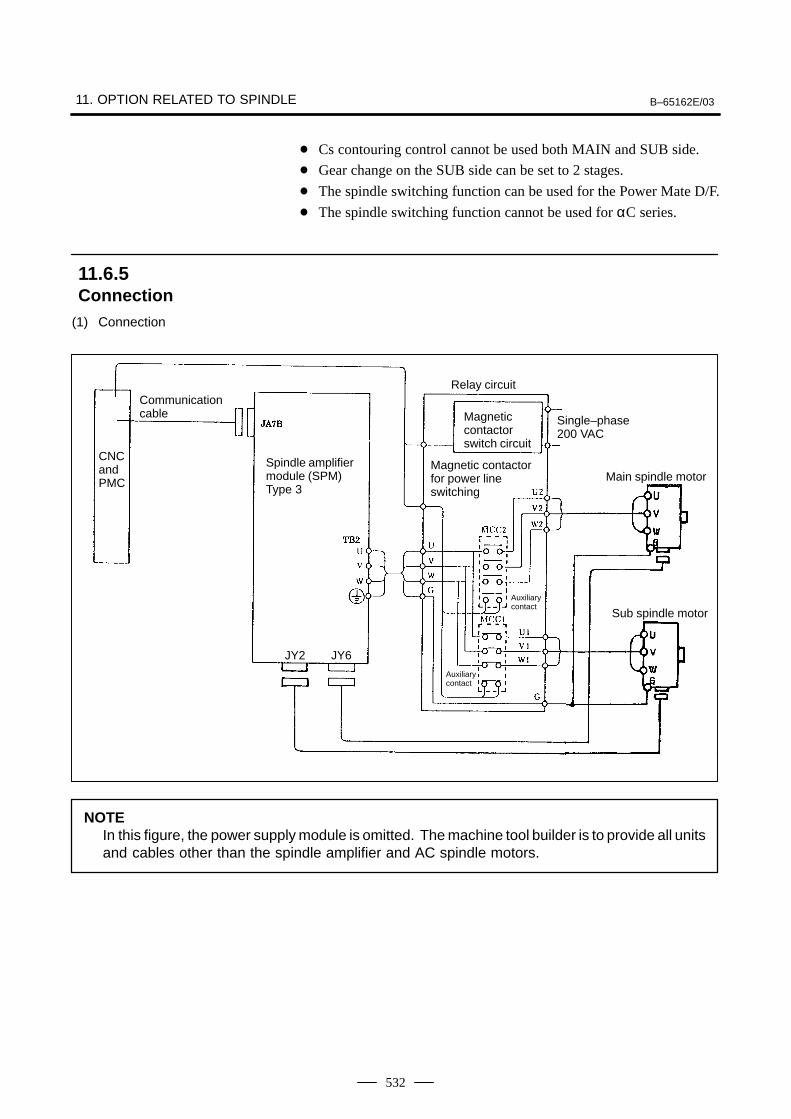
11. OPTION RELATED TO SPINDLE B–65162E/03
532
Cs contouring control cannot be used both MAIN and SUB side.
Gear change on the SUB side can be set to 2 stages.
The spindle switching function can be used for the Power Mate D/F.
The spindle switching function cannot be used for αC series.
(1) Connection
CNCandPMC
Communicationcable
Spindle amplifiermodule (SPM)Type 3
Relay circuit
Magneticcontactorswitch circuit
Single–phase200 VAC
Magnetic contactorfor power lineswitching
Auxiliarycontact
Auxiliarycontact
Main spindle motor
Sub spindle motor
JY2 JY6
NOTEIn this figure, the power supply module is omitted. The machine tool builder is to provide all unitsand cables other than the spindle amplifier and AC spindle motors.
11.6.5Connection
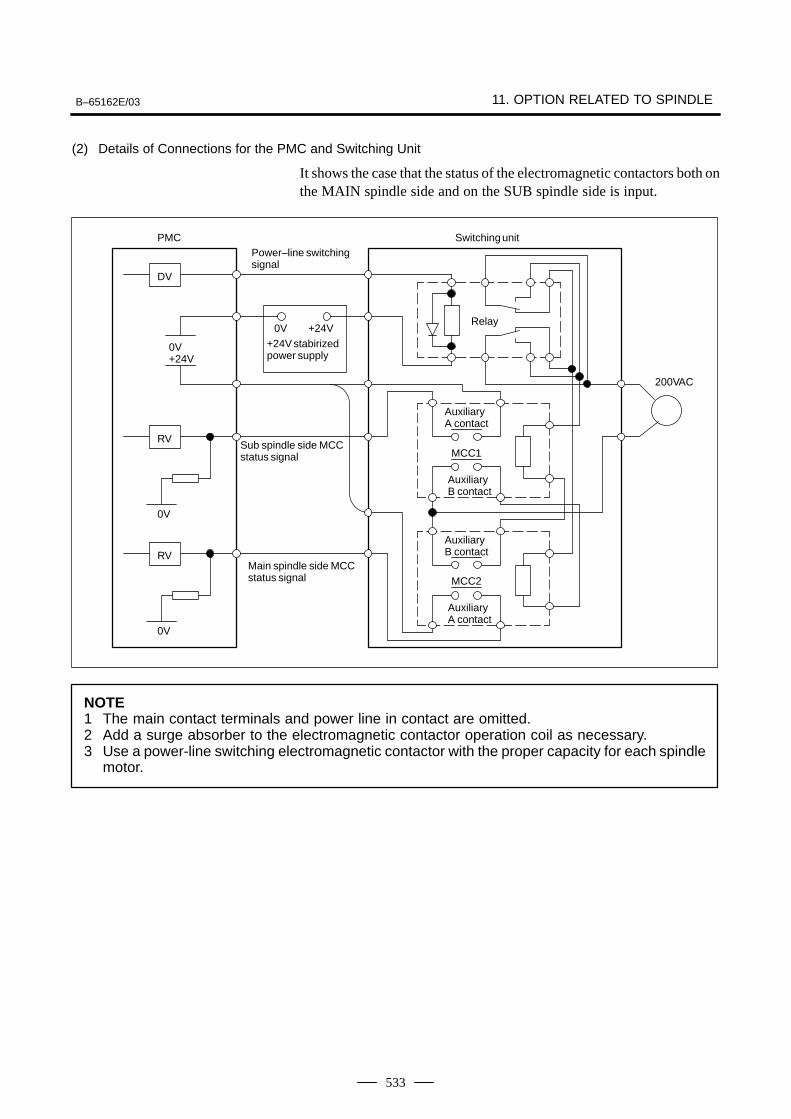
B–65162E/03 11. OPTION RELATED TO SPINDLE
533
(2) Details of Connections for the PMC and Switching Unit
It shows the case that the status of the electromagnetic contactors both onthe MAIN spindle side and on the SUB spindle side is input.
Auxiliary A contact
MCC1
Auxiliary B contact
Auxiliary B contact
MCC2
Auxiliary A contact
Relay
Switching unit
200VAC
Power–line switching signal
+24V stabirizedpower supply
0V +24V
Sub spindle side MCCstatus signal
Main spindle side MCCstatus signal
0V+24V
0V
RV
0V
RV
DV
PMC
NOTE1 The main contact terminals and power line in contact are omitted.2 Add a surge absorber to the electromagnetic contactor operation coil as necessary.3 Use a power-line switching electromagnetic contactor with the proper capacity for each spindle
motor.
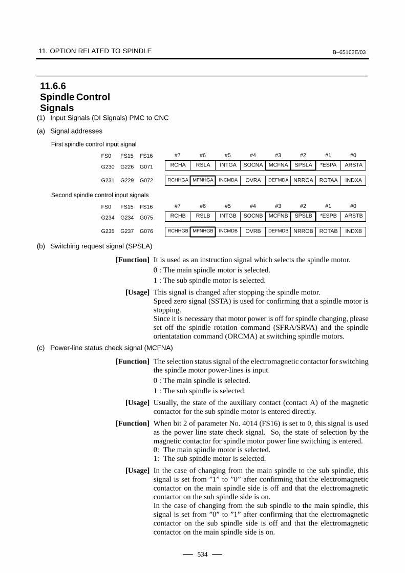
11. OPTION RELATED TO SPINDLE B–65162E/03
534
(1) Input Signals (DI Signals) PMC to CNC
(a) Signal addresses
#7 #6 #5 #4 #3 #2 #1 #0
First spindle control input signal
RCHA RSLA INTGA SOCNA MCFNA SPSLA *ESPA ARSTAG230 G226 G071
RCHHGA MFNHGA INCMDA OVRA DEFMDA NRROA ROTAA INDXAG231 G229 G072
FS0 FS15 FS16
#7 #6 #5 #4 #3 #2 #1 #0FS0 FS15 FS16
Second spindle control input signals
RCHB RSLB INTGB SOCNB MCFNB SPSLB *ESPB ARSTBG234 G234 G075
RCHHGB MFNHGB INCMDB OVRB DEFMDB NRROB ROTAB INDXBG235 G237 G076
(b) Switching request signal (SPSLA)
[Function] It is used as an instruction signal which selects the spindle motor.0 : The main spindle motor is selected.1 : The sub spindle motor is selected.
[Usage] This signal is changed after stopping the spindle motor.Speed zero signal (SSTA) is used for confirming that a spindle motor isstopping.Since it is necessary that motor power is off for spindle changing, pleaseset off the spindle rotation command (SFRA/SRVA) and the spindleorientatation command (ORCMA) at switching spindle motors.
(c) Power-line status check signal (MCFNA)
[Function] The selection status signal of the electromagnetic contactor for switchingthe spindle motor power-lines is input.
0 : The main spindle is selected.1 : The sub spindle is selected.
[Usage] Usually, the state of the auxiliary contact (contact A) of the magneticcontactor for the sub spindle motor is entered directly.
[Function] When bit 2 of parameter No. 4014 (FS16) is set to 0, this signal is usedas the power line state check signal. So, the state of selection by themagnetic contactor for spindle motor power line switching is entered.0: The main spindle motor is selected.1: The sub spindle motor is selected.
[Usage] In the case of changing from the main spindle to the sub spindle, thissignal is set from ”1” to ”0” after confirming that the electromagneticcontactor on the main spindle side is off and that the electromagneticcontactor on the sub spindle side is on.In the case of changing from the sub spindle to the main spindle, thissignal is set from ”0” to ”1” after confirming that the electromagneticcontactor on the sub spindle side is off and that the electromagneticcontactor on the main spindle side is on.
11.6.6Spindle ControlSignals
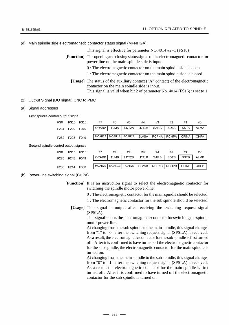
B–65162E/03 11. OPTION RELATED TO SPINDLE
535
(d) Main spindle side electromagnetic contactor status signal (MFNHGA)
This signal is effective for parameter NO.4014 #2=1 (FS16)
[Function] The opening and closing status signal of the electromagnetic contactor forpower-line on the main spindle side is input.
0 : The electromagnetic contactor on the main spindle side is open.
1 : The electromagnetic contactor on the main spindle side is closed.
[Usage] The status of the auxiliary contact (”A” contact) of the electromagneticcontactor on the main spindle side is input.This signal is valid when bit 2 of parameter No. 4014 (FS16) is set to 1.
(2) Output Signal (DO signal) CNC to PMC
(a) Signal addresses
#7 #6 #5 #4 #3 #2 #1 #0
First spindle control output signal
ORARA TLMA LDT2A LDT1A SARA SDTA SSTA ALMAF281 F229 F045
MOAR2A MOAR1A POAR2A SLVSA RCFNA RCHPA CFINA CHPAF282 F228 F049
FS0 FS15 FS16
#7 #6 #5 #4 #3 #2 #1 #0FS0 FS15 FS16
Second spindle control output signals
ORARB TLMB LDT2B LDT1B SARB SDTB SSTB ALMBF285 F245 F049
MOAR2B MOAR1B POAR2B SLVSB RCFNB RCHPB CFINB CHPBF286 F244 F050
(b) Power-line switching signal (CHPA)
[Function] It is an instruction signal to select the electromagnetic contactor forswitching the spindle motor power-line.
0 : The electromagnetic contactor for the main spindle should be selected.
1 : The electromagnetic contactor for the sub spindle should be selected.
[Usage] This signal is output after receiving the switching request signal(SPSLA).This signal selects the electromagnetic contactor for switching the spindlemotor power-line.At changing from the sub spindle to the main spindle, this signal changesfrom ”1” to ”0” after the switching request signal (SPSLA) is received.As a result, the electromagnetic contactor for the sub spindle is first turnedoff. After it is confirmed to have turned off the electromagnetic contactorfor the sub spindle, the electromagnetic contactor for the main spindle isturned on.At changing from the main spindle to the sub spindle, this signal changesfrom ”0” to ”1” after the switching request signal (SPSLA) is received.As a result, the electromagnetic contactor for the main spindle is firstturned off. After it is confirmed to have turned off the electromagneticcontactor for the sub spindle is turned on.
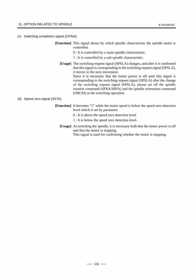
11. OPTION RELATED TO SPINDLE B–65162E/03
536
(c) Switching completion signal (CFINA)
[Function] This signal shows by which spindle characteristic the spindle motor iscontrolled.
0 : It is controlled by a main spindle characteristic.
1 : It is controlled by a sub spindle characteristic.
[Usage] The switching request signal (SPSLA) changes, and after it is confirmedthat this signal is corresponding to the switching request signal (SPSLA),it moves to the next movement.Since it is necessary that the motor power is off until this signal iscorresponding to the switching request signal (SPSLA) after the changeof the switching request signal (SPSLA), please set off the spindlerotation command (SFRA/SRVA) and the spindle orientation command(ORCM) at the switching operation.
(d) Speed zero signal (SSTA)
[Function] It becomes ”1” while the motor speed is below the speed zero detectionlevel which is set by parameter.
0 : It is above the speed zero detection level.
1 : It is below the speed zero detection level.
[Usage] At switching the spindle, it is necessary both that the motor power is offand that the motor is stopping.This signal is used for confirming whether the motor is stopping.
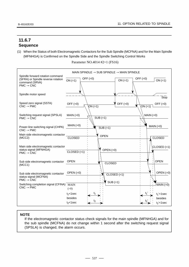
B–65162E/03 11. OPTION RELATED TO SPINDLE
537
(1) When the Status of both Electromagnetic Contactors for the Sub Spindle (MCFNA) and for the Main Spindle
(MFNHGA) is Confirmed on the Spindle Side and the Spindle Switching Control Works
Parameter NO.4014 #2=1 (FS16)
t2
t1
CLOSED (=1)
MAIN (=0)
ON (=1)
MAIN SPINDLE SUB SPINDLE MAIN SPINDLESpindle forward rotation command(SFRA) or Spindle reverse rotationcommand (SRVA) PMC CNC
Spindle motor speed
Speed zero signal (SSTA)CNC PMC
Switching request signal (SPSLA)PMC CNC
Power-line switching signal (CHPA)CNC PMC
Main side electromagnetic contactor(MCC2)
Main side electromagnetic contactorstatus signal (MFNHGA)PMC CNC
Sub side electromagnetic contactor(MCC1)
Sub side electromagnetic contactorstatus signal (MCFNA)PMC CNC
Switching completion signal (CFINA)CNC PMC
ON (=1) ON (=1) ON (=1)OFF (=0) OFF (=0)
Stop
OFF (=0) OFF (=0) OFF (=0)ON (=1)
MAIN (=0) MAIN (=0)
MAIN (=0) MAIN (=0)
SUB (=1)
MAIN(=0)
OPEN (=0)
SUB (=1)
CLOSED (=1)
CLOSEDOPEN
CLOSED
OPEN (=0)CLOSED (=1)
OPEN
OPEN (=0)
CLOSED
SUB (=1)
OPEN
t2’
t1’t1<1sec
besides
t2<1sec
t1’<1sec
besides
t2’<1sec
NOTEIf the electromagnetic contactor status check signals for the main spindle (MFNHGA) and forthe sub spindle (MCFNA) do not change within 1 second after the switching request signal(SPSLA) is changed, the alarm occurs.
11.6.7Sequence
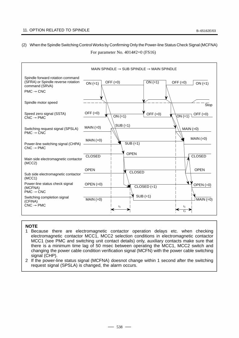
11. OPTION RELATED TO SPINDLE B–65162E/03
538
(2) When the Spindle Switching Control Works by Confirming Only the Power-line Status Check Signal (MCFNA)
For parameter No. 4014#2=0 (FS16)
t1
MAIN (=0)
ON (=1)
MAIN SPINDLE SUB SPINDLE MAIN SPINDLE
Spindle forward rotation command(SFRA) or Spindle reverse rotationcommand (SRVA)
PMC CNC
Spindle motor speed
Speed zero signal (SSTA)CNC PMC
Switching request signal (SPSLA)PMC CNC
Power-line switching signal (CHPA)CNC PMC
Main side electromagnetic contactor(MCC2)
Sub side electromagnetic contactor(MCC1)
Power-line status check signal (MCFNA)PMC CNC
Switching completion signal (CFINA)CNC PMC
ON (=1) ON (=1) ON (=1)OFF (=0) OFF (=0)
Stop
OFF (=0) OFF (=0) OFF (=0)ON (=1)
MAIN (=0) MAIN (=0)
MAIN (=0) MAIN (=0)
SUB (=1)
MAIN (=0)
OPEN (=0)
SUB (=1)
CLOSED (=1)
CLOSEDOPEN
CLOSED
OPEN
OPEN (=0)
CLOSED
SUB (=1)
OPEN
t1G
NOTE1 Because there are electromagnetic contactor operation delays etc. when checking
electromagnetic contactor MCC1, MCC2 selection conditions in electromagnetic contactorMCC1 (see PMC and switching unit contact details) only, auxiliary contacts make sure thatthere is a minimum time lag of 50 msec between operating the MCC1, MCC2 switch andchanging the power cable condition verification signal (MCFN) with the power cable switchingsignal (CHP).
2 If the power-line status signal (MCFNA) doesnot change within 1 second after the switchingrequest signal (SPSLA) is changed, the alarm occurs.
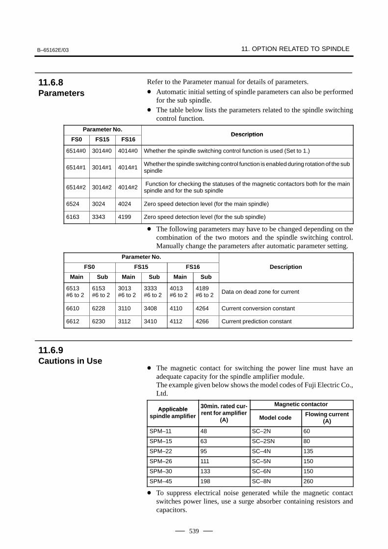
B–65162E/03 11. OPTION RELATED TO SPINDLE
539
Refer to the Parameter manual for details of parameters.
Automatic initial setting of spindle parameters can also be performedfor the sub spindle.
The table below lists the parameters related to the spindle switchingcontrol function.
Parameter No.Description
FS0 FS15 FS16Description
6514#0 3014#0 4014#0 Whether the spindle switching control function is used (Set to 1.)
6514#1 3014#1 4014#1Whether the spindle switching control function is enabled during rotation of the subspindle
6514#2 3014#2 4014#2 Function for checking the statuses of the magnetic contactors both for the mainspindle and for the sub spindle
6524 3024 4024 Zero speed detection level (for the main spindle)
6163 3343 4199 Zero speed detection level (for the sub spindle)
The following parameters may have to be changed depending on thecombination of the two motors and the spindle switching control.Manually change the parameters after automatic parameter setting.
Parameter No.
FS0 FS15 FS16 Description
Main Sub Main Sub Main Sub
6513#6 to 2
6153#6 to 2
3013#6 to 2
3333#6 to 2
4013#6 to 2
4189#6 to 2 Data on dead zone for current
6610 6228 3110 3408 4110 4264 Current conversion constant
6612 6230 3112 3410 4112 4266 Current prediction constant
The magnetic contact for switching the power line must have anadequate capacity for the spindle amplifier module.The example given below shows the model codes of Fuji Electric Co.,Ltd.
Applicable 30min. rated cur- Magnetic contactorApplicable
spindle amplifier
30min. rated current for amplifier
(A) Model code Flowing current(A)
SPM–11 48 SC–2N 60
SPM–15 63 SC–2SN 80
SPM–22 95 SC–4N 135
SPM–26 111 SC–5N 150
SPM–30 133 SC–6N 150
SPM–45 198 SC–8N 260
To suppress electrical noise generated while the magnetic contactswitches power lines, use a surge absorber containing resistors andcapacitors.
11.6.8Parameters
11.6.9Cautions in Use
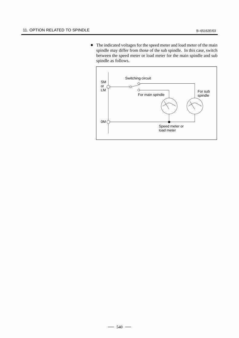
11. OPTION RELATED TO SPINDLE B–65162E/03
540
The indicated voltages for the speed meter and load meter of the mainspindle may differ from those of the sub spindle. In this case, switchbetween the speed meter or load meter for the main spindle and subspindle as follows.
SMorLM
0M
Switching circuit
For main spindleFor subspindle
Speed meter orload meter
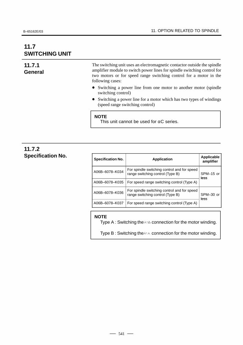
B–65162E/03 11. OPTION RELATED TO SPINDLE
541
The switching unit uses an electromagnetic contactor outside the spindleamplifier module to switch power lines for spindle switching control fortwo motors or for speed range switching control for a motor in thefollowing cases:
Switching a power line from one motor to another motor (spindleswitching control)
Switching a power line for a motor which has two types of windings(speed range switching control)
NOTEThis unit cannot be used for αC series.
Specification No. Application Applicableamplifier
A06B–6078–K034For spindle switching control and for speedrange switching control (Type B) SPM–15 or
lessA06B–6078–K035 For speed range switching control (Type A)
less
A06B–6078–K036For spindle switching control and for speedrange switching control (Type B) SPM–30 or
lessA06B–6078–K037 For speed range switching control (Type A)
less
NOTEType A : Switching the connection for the motor winding.
Type B : Switching the connection for the motor winding.
11.7SWITCHING UNIT
11.7.1General
11.7.2Specification No.
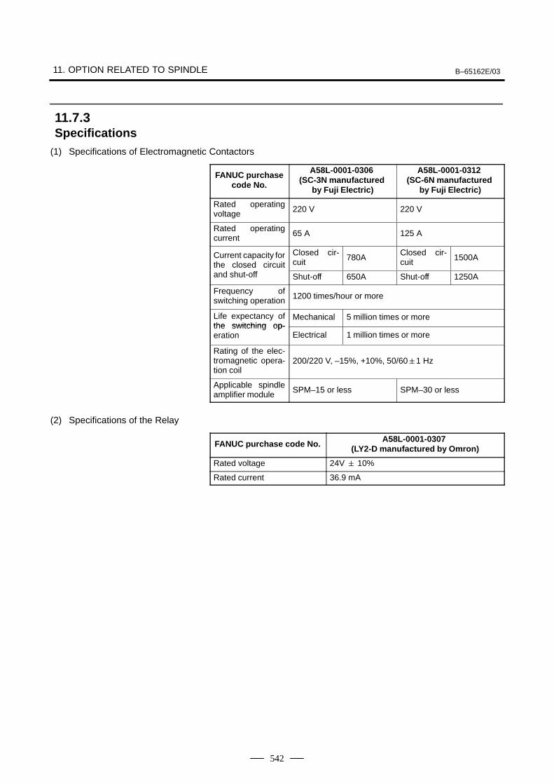
11. OPTION RELATED TO SPINDLE B–65162E/03
542
(1) Specifications of Electromagnetic Contactors
FANUC purchasecode No.
A58L-0001-0306 (SC-3N manufactured
by Fuji Electric)
A58L-0001-0312 (SC-6N manufactured
by Fuji Electric)
Rated operatingvoltage 220 V 220 V
Rated operatingcurrent 65 A 125 A
Current capacity forthe closed circuit
Closed cir-cuit 780A
Closed cir-cuit 1500A
and shut-off Shut-off 650A Shut-off 1250A
Frequency ofswitching operation 1200 times/hour or more
Life expectancy ofthe switching op-
Mechanical 5 million times or morethe switching op-eration Electrical 1 million times or more
Rating of the elec-tromagnetic opera-tion coil
200/220 V, –15%, +10%, 50/601 Hz
Applicable spindleamplifier module SPM–15 or less SPM–30 or less
(2) Specifications of the Relay
FANUC purchase code No. A58L-0001-0307 (LY2-D manufactured by Omron)
Rated voltage 24V 10%
Rated current 36.9 mA
11.7.3Specifications

B–65162E/03 11. OPTION RELATED TO SPINDLE
543
(1) External Dimensions and Dimensions for Mounting the Switching Unit for the Spindle Switching Control and
Speed Range Switching Control (Type B: Connection)
A06B-6059-K034Layout Drawing
MCC2MCC1RELAY
11.7.4External Dimensionsand Dimensions forMounting
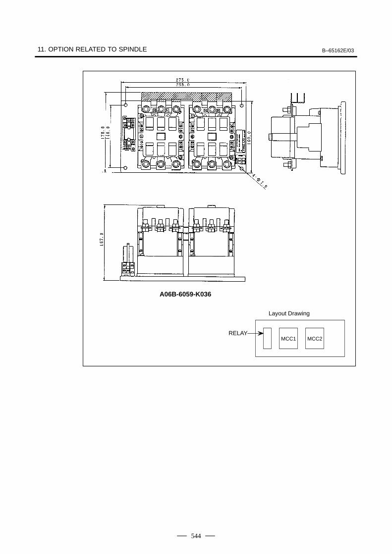
11. OPTION RELATED TO SPINDLE B–65162E/03
544
A06B-6059-K036
Layout Drawing
MCC2MCC1RELAY
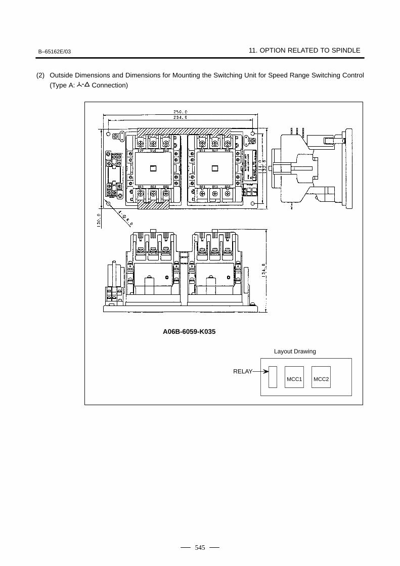
B–65162E/03 11. OPTION RELATED TO SPINDLE
545
(2) Outside Dimensions and Dimensions for Mounting the Switching Unit for Speed Range Switching Control
(Type A: Connection)
A06B-6059-K035
Layout Drawing
MCC2MCC1RELAY
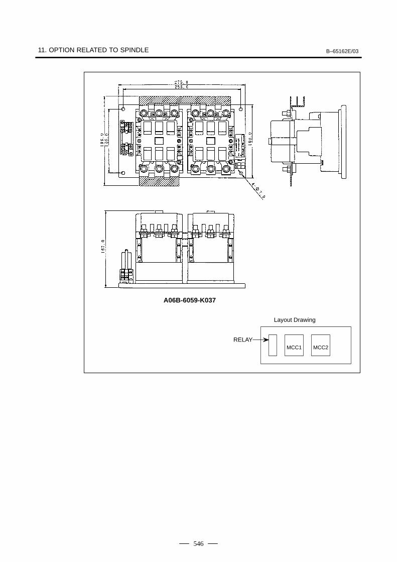
11. OPTION RELATED TO SPINDLE B–65162E/03
546
A06B-6059-K037
Layout Drawing
MCC2MCC1RELAY
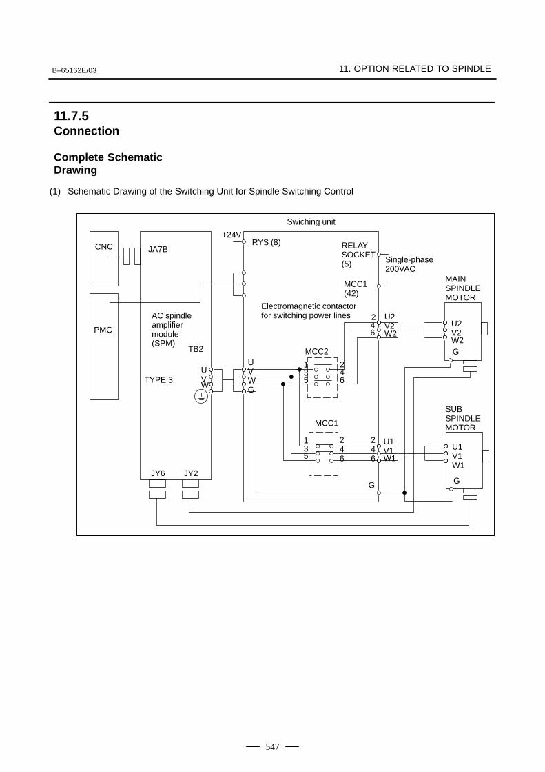
B–65162E/03 11. OPTION RELATED TO SPINDLE
547
(1) Schematic Drawing of the Switching Unit for Spindle Switching Control
2
TB2
MAINSPINDLEMOTOR
CNC
JY2
JA7B
AC spindleamplifiermodule(SPM)
UVWG
UVW
Single-phase200VAC
U2V2W2
U2V2W2
U1V1W1
U1V1W1
GG
Electromagnetic contactorfor switching power lines
PMC
G
SUBSPINDLEMOTOR
135
246
135
246
46
MCC2
MCC1
RELAYSOCKET(5)
MCC1(42)
RYS (8)+24V
JY6
246
Swiching unit
TYPE 3
ÂÂÂÂ
11.7.5Connection
Complete SchematicDrawing
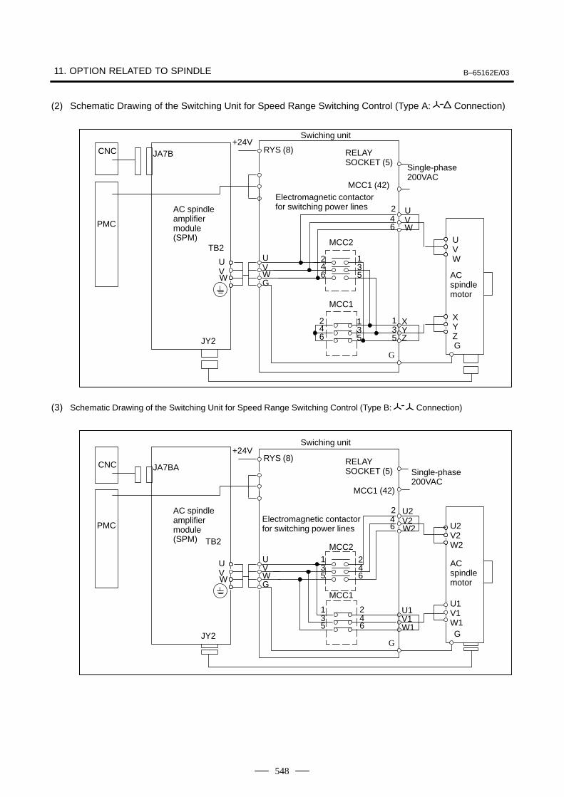
11. OPTION RELATED TO SPINDLE B–65162E/03
548
(2) Schematic Drawing of the Switching Unit for Speed Range Switching Control (Type A: Connection)
2
ACspindlemotor
Swiching unit
UVW
XYZG
G
UVW
46
XY
CNC JA7B
AC spindleamplifiermodule(SPM)
PMC
Single-phase200VAC
Electromagnetic contactorfor switching power lines
RELAYSOCKET (5)
MCC1 (42)
RYS (8)+24V
TB2
JY2
UVWG
UVW
MCC2
135
46
2
135
46
2
MCC1
135 Z
ÂÂÂÂ
(3) Schematic Drawing of the Switching Unit for Speed Range Switching Control (Type B: Connection)
2
ACspindlemotor
Swiching unit
U2V2W2
GG
U2V24
6
135
246
U1V1W1
135
CNC JA7BA
AC spindleamplifiermodule(SPM)
PMC
Single-phase200VAC
Electromagnetic contactorfor switching power lines
RELAYSOCKET (5)
MCC1 (42)
RYS (8)+24V
TB2
JY2
UVWG
UVW
MCC2
246
U1V1W1
MCC1
W2
ÂÂÂÂ
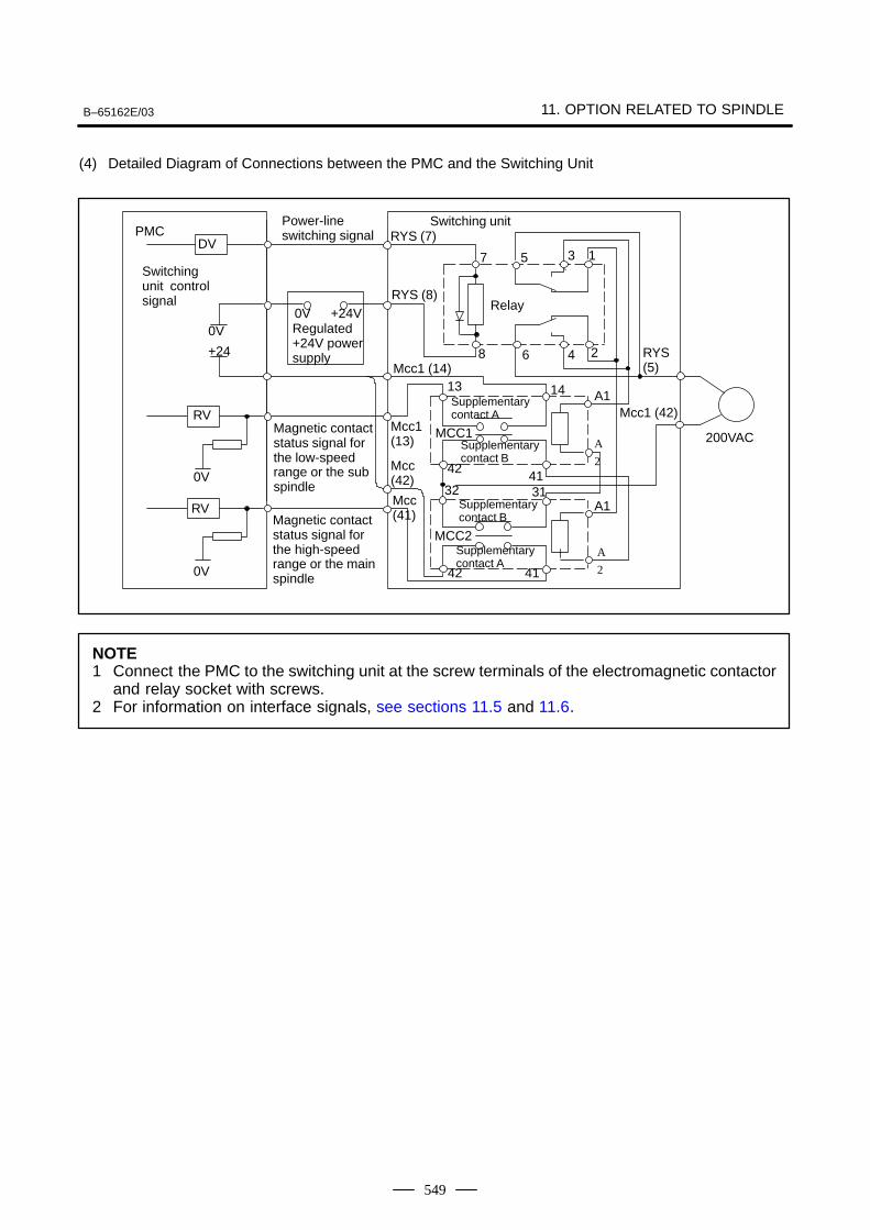
B–65162E/03 11. OPTION RELATED TO SPINDLE
549
(4) Detailed Diagram of Connections between the PMC and the Switching Unit
Mcc(41)
Mcc(42)
Magnetic contactstatus signal forthe high-speedrange or the mainspindle
Magnetic contactstatus signal forthe low-speedrange or the subspindle
Power-lineswitching signal
Switching unit
Supplementarycontact A
PMC
MCC2
0V
+24
MCC1 200VAC
0V
DV
RV
0V
Relay+24V
Regulated+24V powersupply
Supplementarycontact B
Supplementarycontact B
1357
RYS (7)
2468
13
42
324131
A
2
A114
RYS (8)
RYS(5)
Mcc1 (42)
Mcc1 (14)
Mcc1(13)
RV
0V
42 41
Switchingunit controlsignal
0V
A1
A
2
Supplementarycontact A
NOTE1 Connect the PMC to the switching unit at the screw terminals of the electromagnetic contactor
and relay socket with screws.2 For information on interface signals, see sections 11.5 and 11.6.
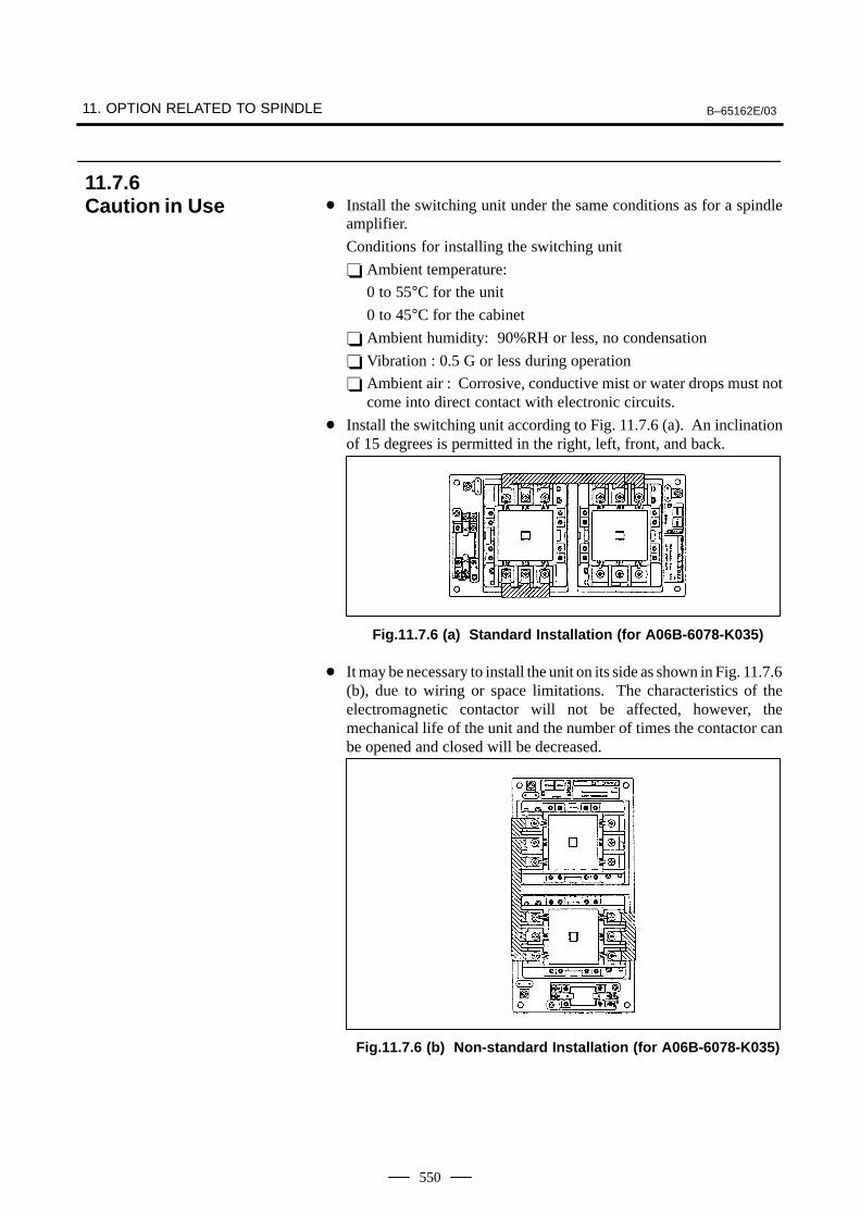
11. OPTION RELATED TO SPINDLE B–65162E/03
550
Install the switching unit under the same conditions as for a spindleamplifier.
Conditions for installing the switching unit
Ambient temperature:
0 to 55°C for the unit
0 to 45°C for the cabinet
Ambient humidity: 90%RH or less, no condensation
Vibration : 0.5 G or less during operation
Ambient air : Corrosive, conductive mist or water drops must notcome into direct contact with electronic circuits.
Install the switching unit according to Fig. 11.7.6 (a). An inclinationof 15 degrees is permitted in the right, left, front, and back.
Fig.11.7.6 (a) Standard Installation (for A06B-6078-K035)
It may be necessary to install the unit on its side as shown in Fig. 11.7.6(b), due to wiring or space limitations. The characteristics of theelectromagnetic contactor will not be affected, however, themechanical life of the unit and the number of times the contactor canbe opened and closed will be decreased.
Fig.11.7.6 (b) Non-standard Installation (for A06B-6078-K035)
11.7.6Caution in Use
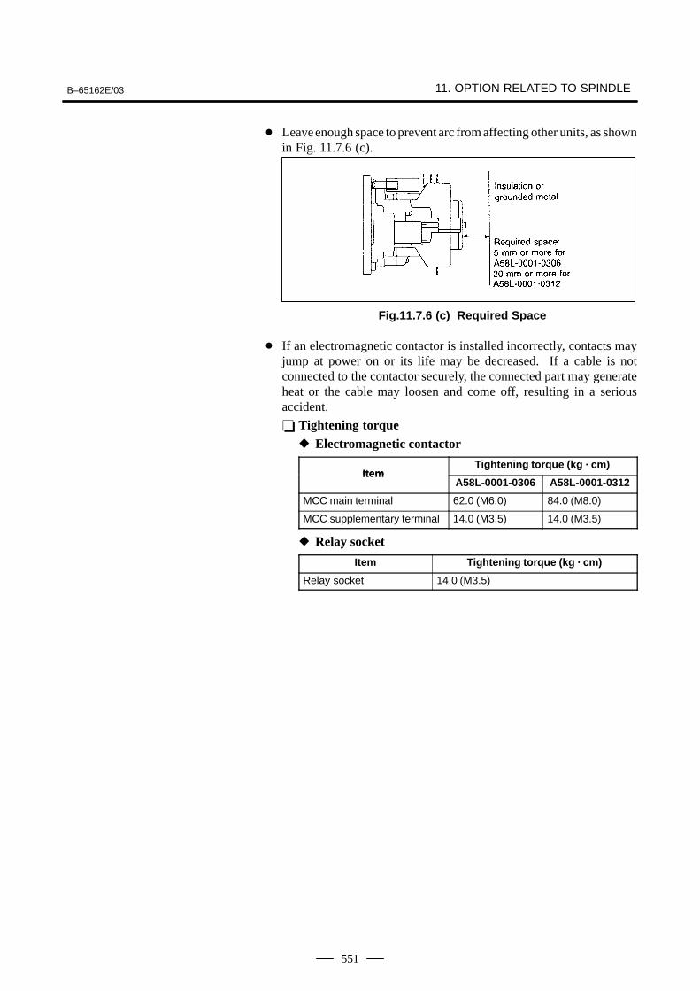
B–65162E/03 11. OPTION RELATED TO SPINDLE
551
Leave enough space to prevent arc from affecting other units, as shownin Fig. 11.7.6 (c).
Fig.11.7.6 (c) Required Space
If an electromagnetic contactor is installed incorrectly, contacts mayjump at power on or its life may be decreased. If a cable is notconnected to the contactor securely, the connected part may generateheat or the cable may loosen and come off, resulting in a seriousaccident.
Tightening torque Electromagnetic contactor
ItemTightening torque (kg · cm)
ItemA58L-0001-0306 A58L-0001-0312
MCC main terminal 62.0 (M6.0) 84.0 (M8.0)
MCC supplementary terminal 14.0 (M3.5) 14.0 (M3.5)
Relay socket
Item Tightening torque (kg · cm)
Relay socket 14.0 (M3.5)
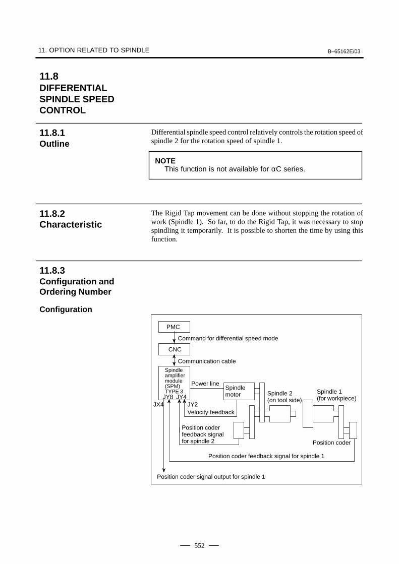
11. OPTION RELATED TO SPINDLE B–65162E/03
552
Differential spindle speed control relatively controls the rotation speed ofspindle 2 for the rotation speed of spindle 1.
NOTEThis function is not available for αC series.
The Rigid Tap movement can be done without stopping the rotation ofwork (Spindle 1). So far, to do the Rigid Tap, it was necessary to stopspindling it temporarily. It is possible to shorten the time by using thisfunction.
PMC
CNC
Command for differential speed mode
Communication cableSpindle amplifier module(SPM)TYPE 3
Power lineSpindle motor
Velocity feedback
Spindle 2 (on tool side)
Spindle 1 (for workpiece)
Position coder
Position coder feedback signal for spindle 2
Position coder feedback signal for spindle 1
Position coder signal output for spindle 1
JY2JX4JY8 JY4
11.8DIFFERENTIALSPINDLE SPEED CONTROL
11.8.1Outline
11.8.2Characteristic
11.8.3Configuration andOrdering Number
Configuration
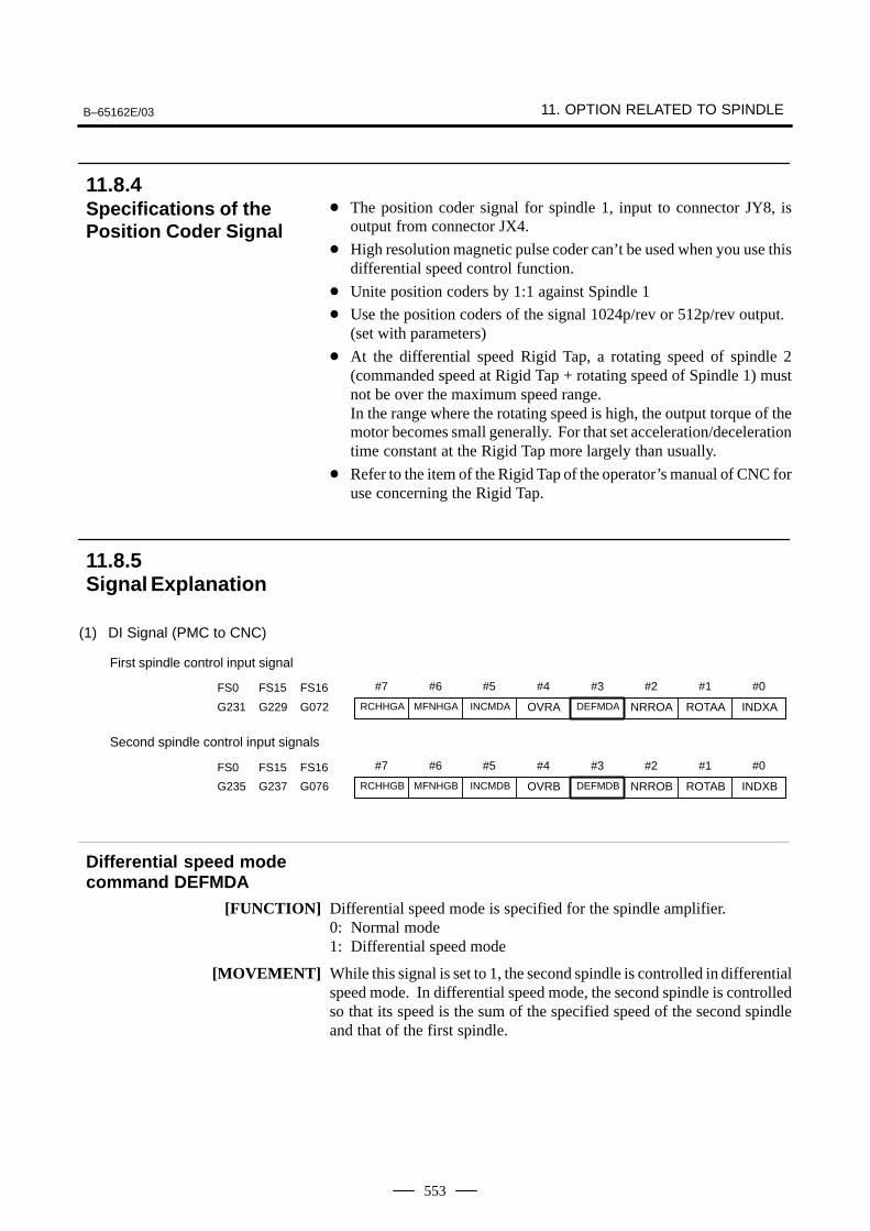
B–65162E/03 11. OPTION RELATED TO SPINDLE
553
The position coder signal for spindle 1, input to connector JY8, isoutput from connector JX4.
High resolution magnetic pulse coder can’t be used when you use thisdifferential speed control function.
Unite position coders by 1:1 against Spindle 1
Use the position coders of the signal 1024p/rev or 512p/rev output.(set with parameters)
At the differential speed Rigid Tap, a rotating speed of spindle 2(commanded speed at Rigid Tap + rotating speed of Spindle 1) mustnot be over the maximum speed range.In the range where the rotating speed is high, the output torque of themotor becomes small generally. For that set acceleration/decelerationtime constant at the Rigid Tap more largely than usually.
Refer to the item of the Rigid Tap of the operator’s manual of CNC foruse concerning the Rigid Tap.
(1) DI Signal (PMC to CNC)
#7 #6 #5 #4 #3 #2 #1 #0
First spindle control input signal
RCHHGA MFNHGA INCMDA OVRA DEFMDA NRROA ROTAA INDXAG231 G229 G072
FS0 FS15 FS16
#7 #6 #5 #4 #3 #2 #1 #0FS0 FS15 FS16
Second spindle control input signals
RCHHGB MFNHGB INCMDB OVRB DEFMDB NRROB ROTAB INDXBG235 G237 G076
[FUNCTION] Differential speed mode is specified for the spindle amplifier.0: Normal mode1: Differential speed mode
[MOVEMENT] While this signal is set to 1, the second spindle is controlled in differentialspeed mode. In differential speed mode, the second spindle is controlledso that its speed is the sum of the specified speed of the second spindleand that of the first spindle.
11.8.4Specifications of thePosition Coder Signal
11.8.5Signal Explanation
Differential speed modecommand DEFMDA
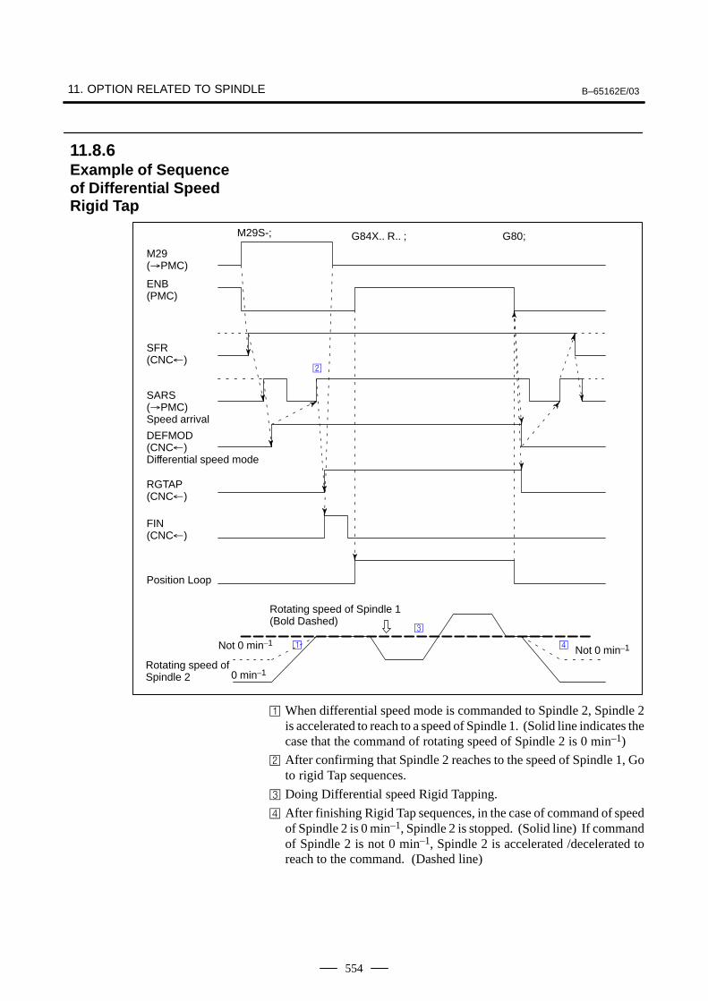
11. OPTION RELATED TO SPINDLE B–65162E/03
554
Not 0 min–1Not 0 min–1
M29(PMC)
ENB(PMC)
SFR(CNC)
SARS(PMC)Speed arrival
DEFMOD(CNC)Differential speed mode
RGTAP(CNC)
FIN(CNC)
Position Loop
Rotating speed of Spindle 1(Bold Dashed)
Rotating speed ofSpindle 2
M29S-; G84X.. R.. ; G80;
0 min–1
When differential speed mode is commanded to Spindle 2, Spindle 2is accelerated to reach to a speed of Spindle 1. (Solid line indicates thecase that the command of rotating speed of Spindle 2 is 0 min–1)
After confirming that Spindle 2 reaches to the speed of Spindle 1, Goto rigid Tap sequences.
Doing Differential speed Rigid Tapping.
After finishing Rigid Tap sequences, in the case of command of speedof Spindle 2 is 0 min–1, Spindle 2 is stopped. (Solid line) If commandof Spindle 2 is not 0 min–1, Spindle 2 is accelerated /decelerated toreach to the command. (Dashed line)
11.8.6Example of Sequenceof Differential SpeedRigid Tap
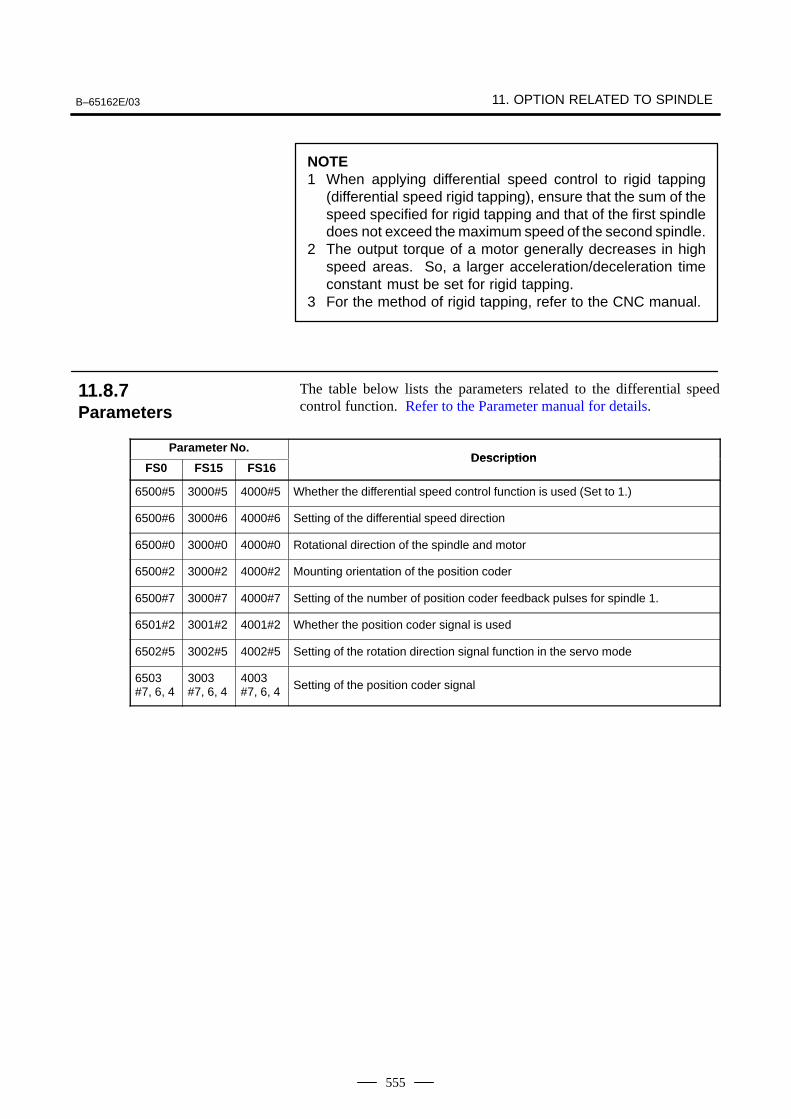
B–65162E/03 11. OPTION RELATED TO SPINDLE
555
NOTE1 When applying differential speed control to rigid tapping
(differential speed rigid tapping), ensure that the sum of thespeed specified for rigid tapping and that of the first spindledoes not exceed the maximum speed of the second spindle.
2 The output torque of a motor generally decreases in highspeed areas. So, a larger acceleration/deceleration timeconstant must be set for rigid tapping.
3 For the method of rigid tapping, refer to the CNC manual.
The table below lists the parameters related to the differential speedcontrol function. Refer to the Parameter manual for details.
Parameter No.Description
FS0 FS15 FS16Description
6500#5 3000#5 4000#5 Whether the differential speed control function is used (Set to 1.)
6500#6 3000#6 4000#6 Setting of the differential speed direction
6500#0 3000#0 4000#0 Rotational direction of the spindle and motor
6500#2 3000#2 4000#2 Mounting orientation of the position coder
6500#7 3000#7 4000#7 Setting of the number of position coder feedback pulses for spindle 1.
6501#2 3001#2 4001#2 Whether the position coder signal is used
6502#5 3002#5 4002#5 Setting of the rotation direction signal function in the servo mode
6503#7, 6, 4
3003#7, 6, 4
4003#7, 6, 4 Setting of the position coder signal
11.8.7Parameters

12. DETECTORS FOR THE SPINDLE B–65162E/03
556
12
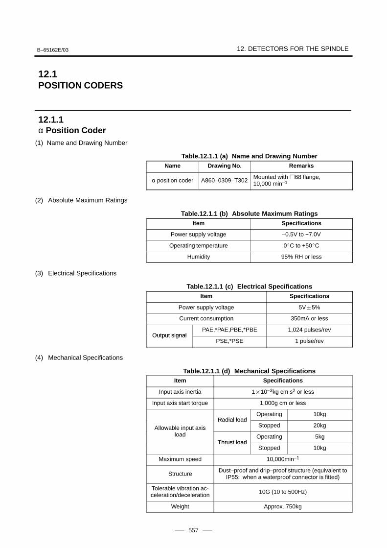
B–65162E/03 12. DETECTORS FOR THE SPINDLE
557
(1) Name and Drawing Number
Table.12.1.1 (a) Name and Drawing NumberName Drawing No. Remarks
α position coder A860–0309–T302Mounted with 68 flange,10,000 min–1
(2) Absolute Maximum Ratings
Table.12.1.1 (b) Absolute Maximum RatingsItem Specifications
Power supply voltage –0.5V to +7.0V
Operating temperature 0C to +50C
Humidity 95% RH or less
(3) Electrical Specifications
Table.12.1.1 (c) Electrical SpecificationsItem Specifications
Power supply voltage 5V5%
Current consumption 350mA or less
Output signalPAE,*PAE,PBE,*PBE 1,024 pulses/rev
Output signalPSE,*PSE 1 pulse/rev
(4) Mechanical Specifications
Table.12.1.1 (d) Mechanical SpecificationsItem Specifications
Input axis inertia 110–3kg cm s2 or less
Input axis start torque 1,000g cm or less
Radial loadOperating 10kg
Allowable input axisRadial load
Stopped 20kgAllowable in ut axisload
Thrust loadOperating 5kg
Thrust loadStopped 10kg
Maximum speed 10,000min–1
StructureDust–proof and drip–proof structure (equivalent to
IP55: when a waterproof connector is fitted)
Tolerable vibration ac-celeration/deceleration 10G (10 to 500Hz)
Weight Approx. 750kg
12.1POSITION CODERS
12.1.1α Position Coder
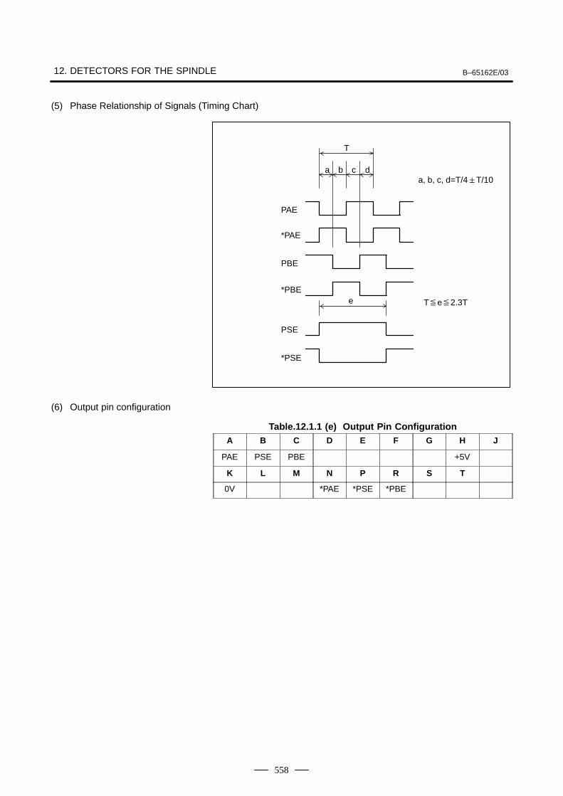
12. DETECTORS FOR THE SPINDLE B–65162E/03
558
(5) Phase Relationship of Signals (Timing Chart)
T
a db c
e
PAE
*PAE
PBE
*PBE
PSE
*PSE
a, b, c, d=T/4T/10
Te2.3T
(6) Output pin configuration
Table.12.1.1 (e) Output Pin ConfigurationA B C D E F G H J
PAE PSE PBE +5V
K L M N P R S T
0V *PAE *PSE *PBE
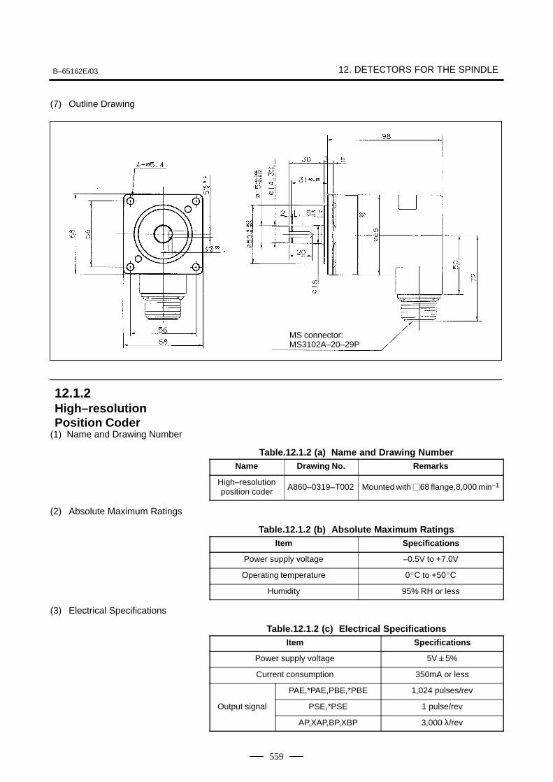
B–65162E/03 12. DETECTORS FOR THE SPINDLE
559
(7) Outline Drawing
MS connector: MS3102A–20–29P
(1) Name and Drawing Number
Table.12.1.2 (a) Name and Drawing NumberName Drawing No. Remarks
High–resolutionposition coder A860–0319–T002 Mounted with 68 flange,8,000 min–1
(2) Absolute Maximum Ratings
Table.12.1.2 (b) Absolute Maximum RatingsItem Specifications
Power supply voltage –0.5V to +7.0V
Operating temperature 0C to +50C
Humidity 95% RH or less
(3) Electrical Specifications
Table.12.1.2 (c) Electrical SpecificationsItem Specifications
Power supply voltage 5V5%
Current consumption 350mA or less
PAE,*PAE,PBE,*PBE 1,024 pulses/rev
Output signal PSE,*PSE 1 pulse/rev
AP,XAP,BP,XBP 3,000 λ/rev
12.1.2High–resolutionPosition Coder
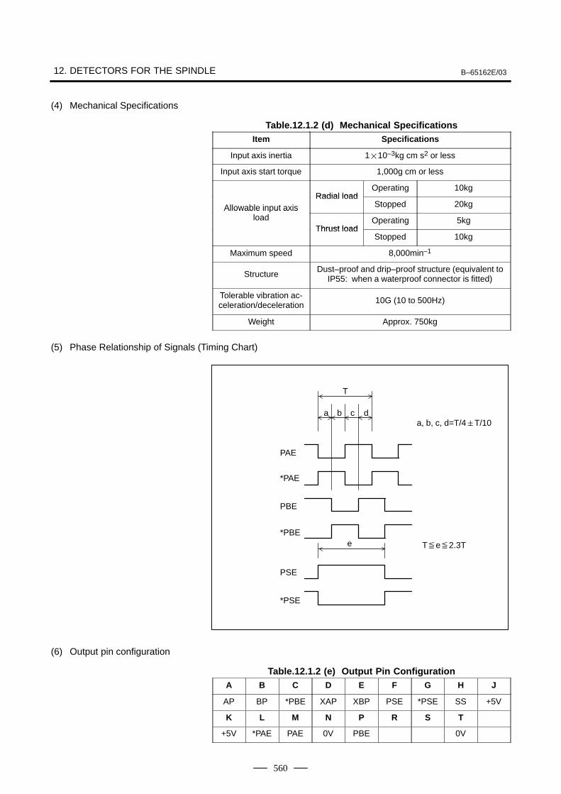
12. DETECTORS FOR THE SPINDLE B–65162E/03
560
(4) Mechanical Specifications
Table.12.1.2 (d) Mechanical SpecificationsItem Specifications
Input axis inertia 110–3kg cm s2 or less
Input axis start torque 1,000g cm or less
Radial loadOperating 10kg
Allowable input axisRadial load
Stopped 20kgAllowable in ut axisload
Thrust loadOperating 5kg
Thrust loadStopped 10kg
Maximum speed 8,000min–1
StructureDust–proof and drip–proof structure (equivalent to
IP55: when a waterproof connector is fitted)
Tolerable vibration ac-celeration/deceleration 10G (10 to 500Hz)
Weight Approx. 750kg
(5) Phase Relationship of Signals (Timing Chart)
T
a db c
e
PAE
*PAE
PBE
*PBE
PSE
*PSE
a, b, c, d=T/4T/10
Te2.3T
(6) Output pin configuration
Table.12.1.2 (e) Output Pin ConfigurationA B C D E F G H J
AP BP *PBE XAP XBP PSE *PSE SS +5V
K L M N P R S T
+5V *PAE PAE 0V PBE 0V
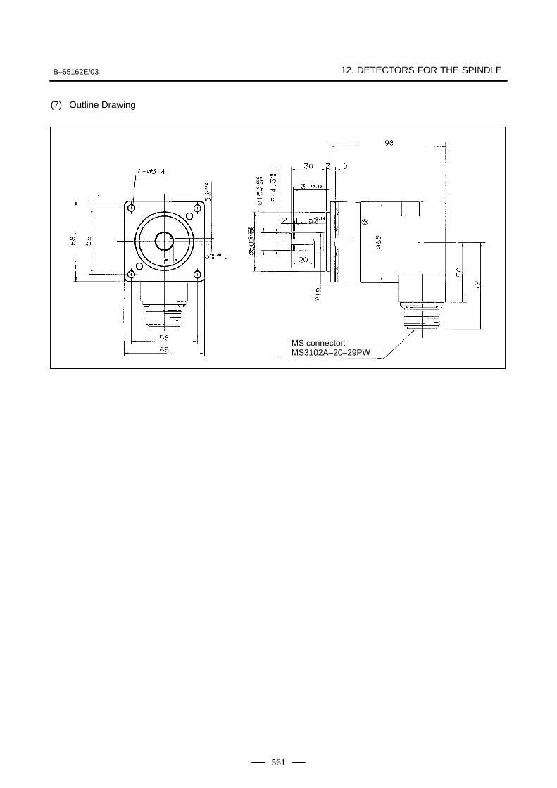
B–65162E/03 12. DETECTORS FOR THE SPINDLE
561
(7) Outline Drawing
MS connector: MS3102A–20–29PW
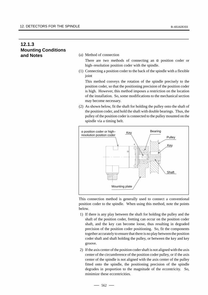
12. DETECTORS FOR THE SPINDLE B–65162E/03
562
(a) Method of connection
There are two methods of connecting an α position coder orhigh–resolution position coder with the spindle.
(1) Connecting a position coder to the back of the spindle with a flexiblejoint
This method conveys the rotation of the spindle precisely to theposition coder, so that the positioning precision of the position coderis high. However, this method imposes a restriction on the locationof the installation. So, some modifications to the mechanical sectionmay become necessary.
(2) As shown below, fit the shaft for holding the pulley onto the shaft ofthe position coder, and hold the shaft with double bearings. Thus, thepulley of the position coder is connected to the pulley mounted on thespindle via a timing belt.
α position coder or high–resolution position coder
Key Bearing
Pulley
Shaft
Mounting plate
Key
This connection method is generally used to connect a conventionalposition coder to the spindle. When using this method, note the pointsbelow.
1) If there is any play between the shaft for holding the pulley and theshaft of the position coder, fretting can occur on the position codershaft, and the key can become loose, thus resulting in degradedprecision of the position coder positioning. So, fit the componentstogether accurately to ensure that there is no play between the positioncoder shaft and shaft holding the pulley, or between the key and keygroove.
2) If the axis center of the position coder shaft is not aligned with the axiscenter of the circumference of the position coder pulley, or if the axiscenter of the spindle is not aligned with the axis center of the pulleyfitted onto the spindle, the positioning precision of the spindledegrades in proportion to the magnitude of the eccentricity. So,minimize these eccentricities.
12.1.3Mounting Conditionsand Notes

B–65162E/03 12. DETECTORS FOR THE SPINDLE
563
(b) Shock
The position coders are precision detectors. So, be careful to protectthe position coders from shock.
(c) Atmosphere
The position coders conform to protection class IP55. However, thisclass specifies short–term performance. So, ensure that the positioncoders are not exposed to coolant or lubricant, and that oil does notbuild up on the position coders. If a position coder is exposed tocoolant or lubricant, place a protection cover over the position coder.
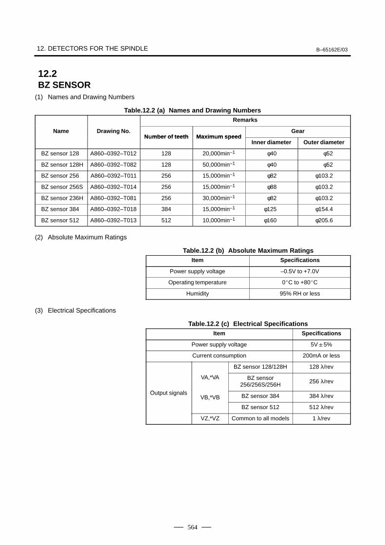
12. DETECTORS FOR THE SPINDLE B–65162E/03
564
(1) Names and Drawing Numbers
Table.12.2 (a) Names and Drawing NumbersRemarks
Name Drawing No.N mber of teeth Maxim m speed
GearNumber of teeth Maximum speed
Inner diameter Outer diameter
BZ sensor 128 A860–0392–T012 128 20,000min–1 φ40 φ52
BZ sensor 128H A860–0392–T082 128 50,000min–1 φ40 φ52
BZ sensor 256 A860–0392–T011 256 15,000min–1 φ82 φ103.2
BZ sensor 256S A860–0392–T014 256 15,000min–1 φ88 φ103.2
BZ sensor 236H A860–0392–T081 256 30,000min–1 φ82 φ103.2
BZ sensor 384 A860–0392–T018 384 15,000min–1 φ125 φ154.4
BZ sensor 512 A860–0392–T013 512 10,000min–1 φ160 φ205.6
(2) Absolute Maximum Ratings
Table.12.2 (b) Absolute Maximum RatingsItem Specifications
Power supply voltage –0.5V to +7.0V
Operating temperature 0C to +80C
Humidity 95% RH or less
(3) Electrical Specifications
Table.12.2 (c) Electrical SpecificationsItem Specifications
Power supply voltage 5V5%
Current consumption 200mA or less
BZ sensor 128/128H 128 λ/rev
O t t i l
VA,*VA BZ sensor256/256S/256H 256 λ/rev
Output signalsVB,*VB BZ sensor 384 384 λ/rev
BZ sensor 512 512 λ/rev
VZ,*VZ Common to all models 1 λ/rev
12.2BZ SENSOR
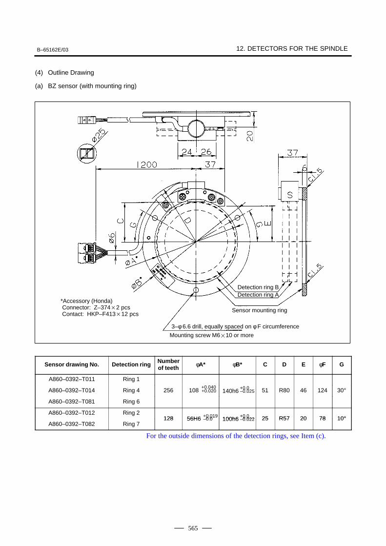
B–65162E/03 12. DETECTORS FOR THE SPINDLE
565
(4) Outline Drawing
(a) BZ sensor (with mounting ring)
*Accessory (Honda) Connector: Z–3742 pcs Contact: HKP–F41312 pcs
Detection ring BDetection ring A
Sensor mounting ring
3–φ 6.6 drill, equally spaced on φ F circumference
Mounting screw M610 or more
Sensor drawing No. Detection ring Numberof teeth φA* φB* C D E φF G
A860–0392–T011 Ring 10 040 0 0A860–0392–T014 Ring 4 256 108
+0.040+0.020 140h6
+0.0–0.025 51 R80 46 124 30°
A860–0392–T081 Ring 6
A860–0392–T012 Ring 2128 56H6 +0.019
–0 0 100h6+0.0
0 022 25 R57 20 78 10°A860–0392–T082 Ring 7
128 56H6 +0.019–0.0 100h6
+0.0–0.022 25 R57 20 78 10°
For the outside dimensions of the detection rings, see Item (c).
12. DETECTORS FOR THE SPINDLE B–65162E/03
566
NOTE– Use the BZ sensor at temperatures not exceeding 80°C.– The BZ sensor is a precision device. It must be handled with care. In particular, ensure that
no force is applied to the S section.– The sensor is an electronic device. Provide dust and drip protection on the machine so that
the sensor is not exposed to chips, oil, water, or any other harmful substance.– Those dimensions that are marked with an asterisk (*) are the dimensions of the sensor
mounting ring. Design a socket and spigot joint on the machine side to match the dimensions.If a socket joint on the machine side is designed incorrectly, an incorrect signal may be output.
– The gap between the sensor and detection ring is adjusted beforehand. However, an outputsignal may not satisfy the specified value due to a socket and spigot joint error. Check theoutput signals when mounting a sensor. If an output signal does not satisfy a specified value,adjust the gap. For information about the output signal level for gap adjustment, refer to PartII of ”FANUC Built–in AC Spindle Motor α Series Descriptions (B–65202EN).”
– Make a shielded wire connection.– To ensure ease of maintenance, install a sensor in a location where it can be replaced easily.– The detection ring of a sensor can be exchanged with another sensor provided the sensors
have the same drawing number.– A sensor and detection ring cannot be combined if the detection ring is designed for a drawing
number different from that of the sensor.– A mating connector (accessory) is provided with the BZ sensor.
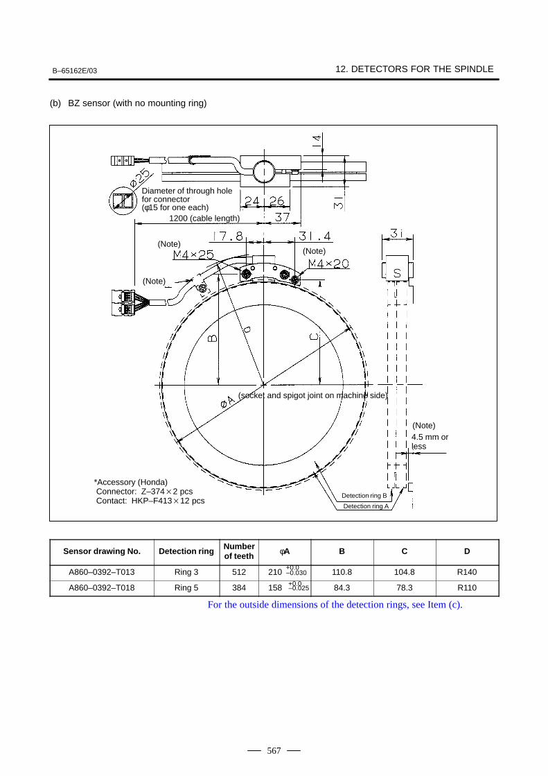
B–65162E/03 12. DETECTORS FOR THE SPINDLE
567
(b) BZ sensor (with no mounting ring)
Diameter of through holefor connector (φ15 for one each)
1200 (cable length)
(Note)
(Note)
(Note)
(Note)
(socket and spigot joint on machine side)
4.5 mm orless
*Accessory (Honda) Connector: Z–3742 pcs Contact: HKP–F41312 pcs
Detection ring B
Detection ring A
Sensor drawing No. Detection ring Numberof teeth φA B C D
A860–0392–T013 Ring 3 512 210+0.0–0.030 110.8 104.8 R140
A860–0392–T018 Ring 5 384 158 +0.0–0.025 84.3 78.3 R110
For the outside dimensions of the detection rings, see Item (c).
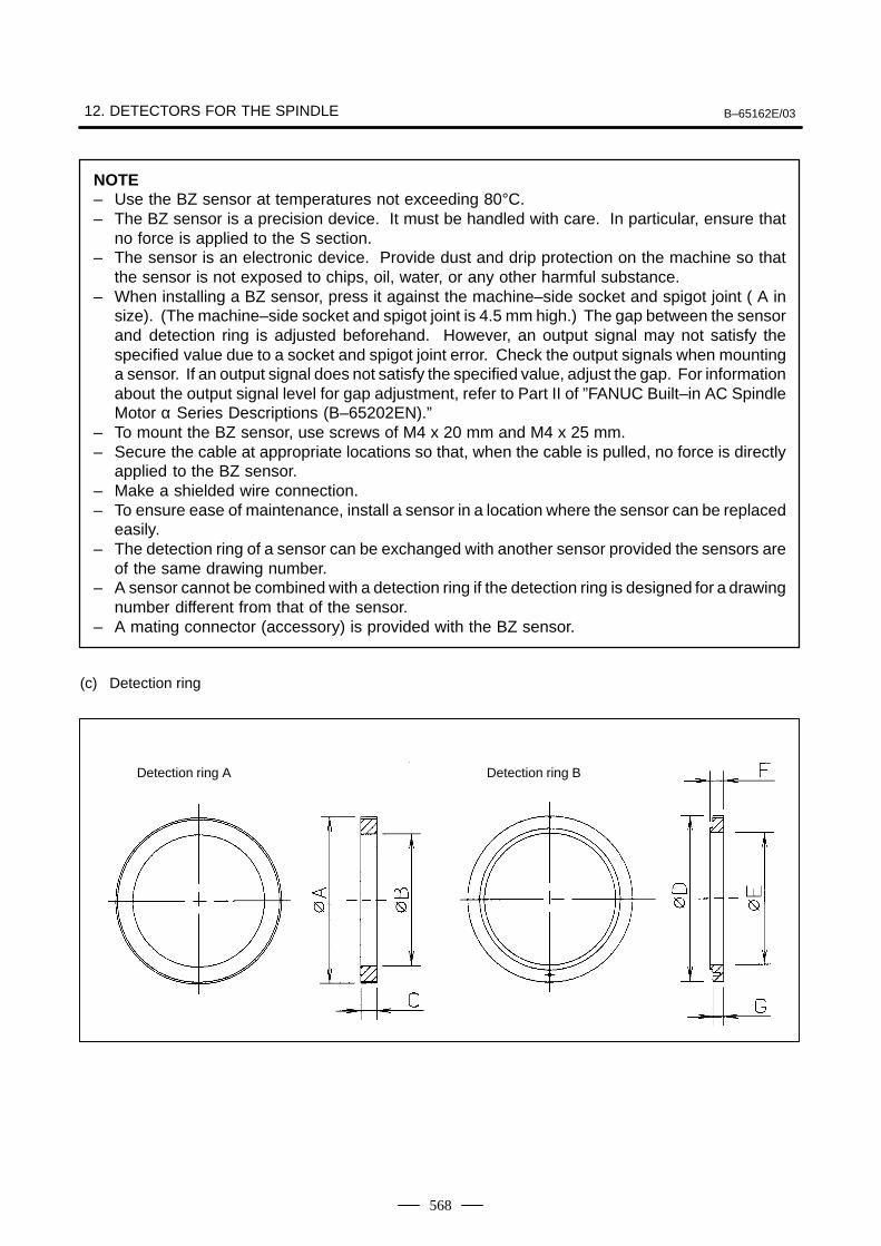
12. DETECTORS FOR THE SPINDLE B–65162E/03
568
NOTE– Use the BZ sensor at temperatures not exceeding 80°C.– The BZ sensor is a precision device. It must be handled with care. In particular, ensure that
no force is applied to the S section.– The sensor is an electronic device. Provide dust and drip protection on the machine so that
the sensor is not exposed to chips, oil, water, or any other harmful substance.– When installing a BZ sensor, press it against the machine–side socket and spigot joint ( A in
size). (The machine–side socket and spigot joint is 4.5 mm high.) The gap between the sensorand detection ring is adjusted beforehand. However, an output signal may not satisfy thespecified value due to a socket and spigot joint error. Check the output signals when mountinga sensor. If an output signal does not satisfy the specified value, adjust the gap. For informationabout the output signal level for gap adjustment, refer to Part II of ”FANUC Built–in AC SpindleMotor α Series Descriptions (B–65202EN).”
– To mount the BZ sensor, use screws of M4 x 20 mm and M4 x 25 mm.– Secure the cable at appropriate locations so that, when the cable is pulled, no force is directly
applied to the BZ sensor.– Make a shielded wire connection.– To ensure ease of maintenance, install a sensor in a location where the sensor can be replaced
easily.– The detection ring of a sensor can be exchanged with another sensor provided the sensors are
of the same drawing number.– A sensor cannot be combined with a detection ring if the detection ring is designed for a drawing
number different from that of the sensor.– A mating connector (accessory) is provided with the BZ sensor.
(c) Detection ring
Detection ring A Detection ring B
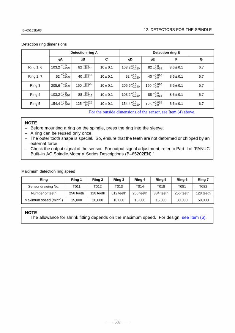
B–65162E/03 12. DETECTORS FOR THE SPINDLE
569
Detection ring dimensions
Detection ring A Detection ring B
φA φB C φD φE F G
Ring 1, 6 103.2+0.0–0.020 82 +0.0
–0.018 100.1 103.2+0.0–0.020 82 +0.0
–0.018 8.60.1 6.7
Ring 2, 7 52+0.0–0.020 40 +0.016
–0.0 100.1 52 +0.0–0.020 40 +0.016
–0.0 8.60.1 6.7
Ring 3 205.6+0.0–0.020 160 +0.020
–0.0 100.1 205.6+0.0–0.020 160 +0.020
–0.0 8.60.1 6.7
Ring 4 103.2 +0.0–0.020 88 +0.0
–0.018 100.1 103.2+0.0–0.020 88 +0.0
–0.018 8.60.1 6.7
Ring 5 154.4 +0.0–0.020 125 +0.025
–0.0 100.1 154.4+0.0–0.020 125 +0.025
–0.0 8.60.1 6.7
For the outside dimensions of the sensor, see Item (4) above.
NOTE– Before mounting a ring on the spindle, press the ring into the sleeve.– A ring can be reused only once.– The outer tooth shape is special. So, ensure that the teeth are not deformed or chipped by an
external force.– Check the output signal of the sensor. For output signal adjustment, refer to Part II of ”FANUC
Built–in AC Spindle Motor α Series Descriptions (B–65202EN).”
Maximum detection ring speed
Ring Ring 1 Ring 2 Ring 3 Ring 4 Ring 5 Ring 6 Ring 7
Sensor drawing No. T011 T012 T013 T014 T018 T081 T082
Number of teeth 256 teeth 128 teeth 512 teeth 256 teeth 384 teeth 256 teeth 128 teeth
Maximum speed (min–1) 15,000 20,000 10,000 15,000 15,000 30,000 50,000
NOTEThe allowance for shrink fitting depends on the maximum speed. For design, see Item (6).
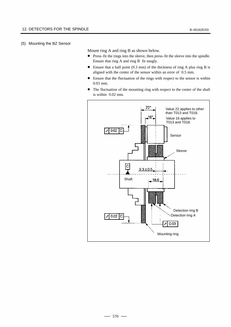
12. DETECTORS FOR THE SPINDLE B–65162E/03
570
(5) Mounting the BZ Sensor
Mount ring A and ring B as shown below. Press–fit the rings into the sleeve, then press–fit the sleeve into the spindle.
Ensure that ring A and ring B fit snugly.
Ensure that a half point (9.3 mm) of the thickness of ring A plus ring B isaligned with the center of the sensor within an error of 0.5 mm.
Ensure that the fluctuation of the rings with respect to the sensor is within0.03 mm.
The fluctuation of the mounting ring with respect to the center of the shaftis within 0.02 mm.
Value 22 applies to otherthan T013 and T018.
Value 16 applies toT013 and T018.
Sensor
Sleeve
Shaft
Detection ring BDetection ring A
Mounting ring
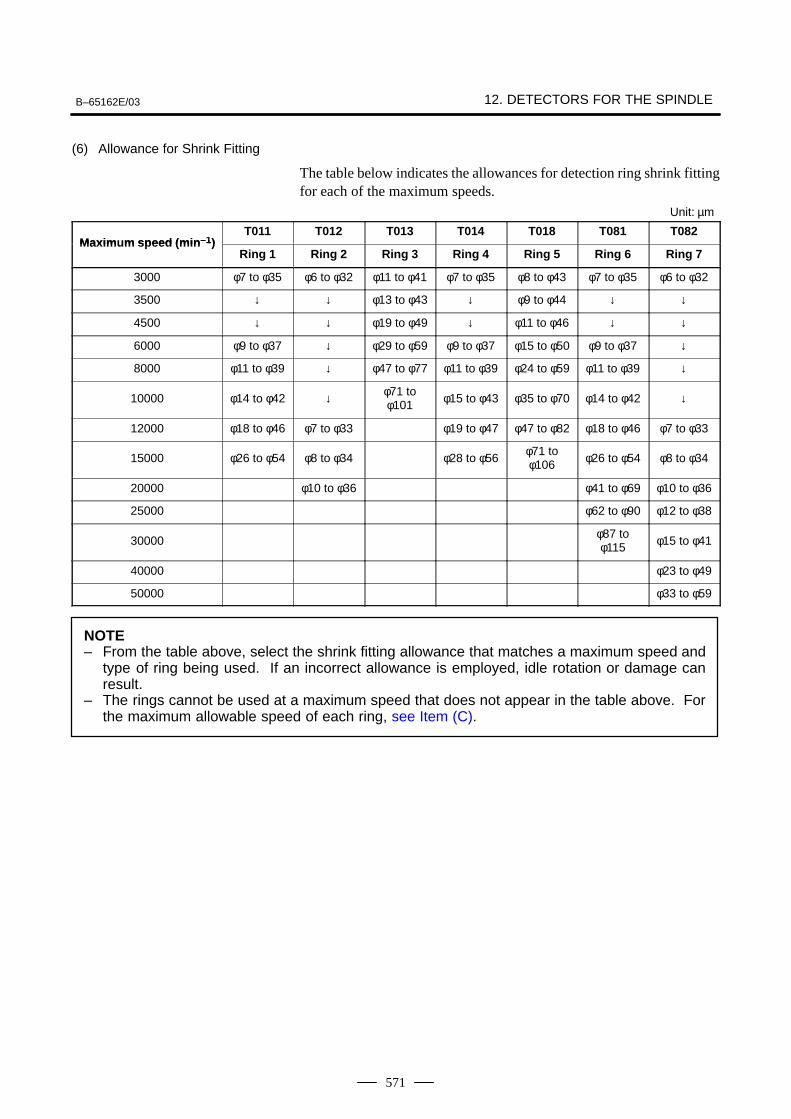
B–65162E/03 12. DETECTORS FOR THE SPINDLE
571
(6) Allowance for Shrink Fitting
The table below indicates the allowances for detection ring shrink fittingfor each of the maximum speeds.
Unit: µm
Maxim m speed (min –1)T011 T012 T013 T014 T018 T081 T082
Maximum speed (min –1)Ring 1 Ring 2 Ring 3 Ring 4 Ring 5 Ring 6 Ring 7
3000 φ7 to φ35 φ6 to φ32 φ11 to φ41 φ7 to φ35 φ8 to φ43 φ7 to φ35 φ6 to φ32
3500 ↓ ↓ φ13 to φ43 ↓ φ9 to φ44 ↓ ↓
4500 ↓ ↓ φ19 to φ49 ↓ φ11 to φ46 ↓ ↓
6000 φ9 to φ37 ↓ φ29 to φ59 φ9 to φ37 φ15 to φ50 φ9 to φ37 ↓
8000 φ11 to φ39 ↓ φ47 to φ77 φ11 to φ39 φ24 to φ59 φ11 to φ39 ↓
10000 φ14 to φ42 ↓ φ71 toφ101 φ15 to φ43 φ35 to φ70 φ14 to φ42 ↓
12000 φ18 to φ46 φ7 to φ33 φ19 to φ47 φ47 to φ82 φ18 to φ46 φ7 to φ33
15000 φ26 to φ54 φ8 to φ34 φ28 to φ56φ71 toφ106 φ26 to φ54 φ8 to φ34
20000 φ10 to φ36 φ41 to φ69 φ10 to φ36
25000 φ62 to φ90 φ12 to φ38
30000φ87 toφ115 φ15 to φ41
40000 φ23 to φ49
50000 φ33 to φ59
NOTE– From the table above, select the shrink fitting allowance that matches a maximum speed and
type of ring being used. If an incorrect allowance is employed, idle rotation or damage canresult.
– The rings cannot be used at a maximum speed that does not appear in the table above. Forthe maximum allowable speed of each ring, see Item (C).
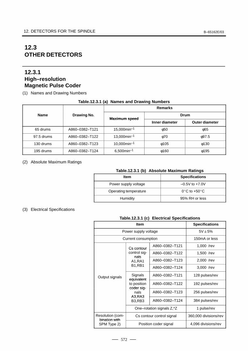
12. DETECTORS FOR THE SPINDLE B–65162E/03
572
(1) Names and Drawing Numbers
Table.12.3.1 (a) Names and Drawing NumbersRemarks
Name Drawing No.Maxim m speed
DrumMaximum speed
Inner diameter Outer diameter
65 drums A860–0382–T121 15,000min–1 φ50 φ65
97.5 drums A860–0382–T122 13,000min–1 φ70 φ97.5
130 drums A860–0382–T123 10,000min–1 φ105 φ130
195 drums A860–0382–T124 6,500min–1 φ160 φ195
(2) Absolute Maximum Ratings
Table.12.3.1 (b) Absolute Maximum RatingsItem Specifications
Power supply voltage –0.5V to +7.0V
Operating temperature 0C to +50C
Humidity 95% RH or less
(3) Electrical Specifications
Table.12.3.1 (c) Electrical SpecificationsItem Specifications
Power supply voltage 5V5%
Current consumption 150mA or less
Cs contourA860–0382–T121 1,000 /rev
Cs contourcontrol sig-
nalsA860–0382–T122 1,500 /rev
nalsA1,RA1B1 RB1
A860–0382–T123 2,000 /revB1,RB1 A860–0382–T124 3,000 /rev
Output signals Signalsequivalent
A860–0382–T121 128 pulses/revgequivalentto positioncoder sig-
A860–0382–T122 192 pulses/revcoder sig-
nalsA3 RA3
A860–0382–T123 256 pulses/revA3,RA3B3,RB3 A860–0382–T124 384 pulses/rev
One–rotation signals Z,*Z 1 pulse/rev
Resolution (com-bination with
Cs contour control signal 360,000 divisions/revbination withSPM Type 2) Position coder signal 4,096 divisions/rev
12.3OTHER DETECTORS
12.3.1High–resolutionMagnetic Pulse Coder
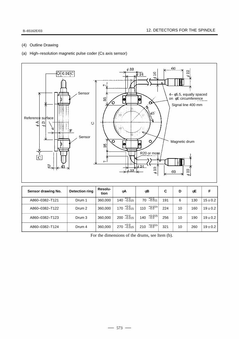
B–65162E/03 12. DETECTORS FOR THE SPINDLE
573
(4) Outline Drawing
(a) High–resolution magnetic pulse coder (Cs axis sensor)
Sensor
Sensor
Reference surface
Magnetic drum
Signal line 400 mm
4– φ5.5, equally spacedon φE circumference
R20 or more
Sensor drawing No. Detection ring Resolu-tion φA φB C D φE F
A860–0382–T121 Drum 1 360,000 140+0.0–0.015 70 +0.0
–0.011 191 6 130 150.2
A860–0382–T122 Drum 2 360,000 170+0.0–0.015 110 +0.015
–0.0 224 10 160 190.2
A860–0382–T123 Drum 3 360,000 200+0.0–0.015 140 +0.015
–0.0 256 10 190 190.2
A860–0382–T124 Drum 4 360,000 270+0.0–0.015 210 +0.015
–0.0 321 10 260 190.2
For the dimensions of the drums, see Item (b).
12. DETECTORS FOR THE SPINDLE B–65162E/03
574
NOTE– Use this sensor at temperatures not exceeding 50°C.– The high–resolution magnetic pulse coder is equipped with a preamplifier.– A sensor set consisting of a magnetic drum, sensor, and preamplifier is adjusted prior to
shipment, and the same serial number is stamped onto each of the components constitutingthat set. When using this sensor, check the serial numbers to ensure that the sensor set doesnot include a component having a different serial number. Moreover, never detach the sensorfrom its mounting plate.
– This sensor consists of electronic circuits and includes many magnetic components. Neverexpose the sensor to a magnetic field of 20 gauss or more. Be careful not to place the sensorin a magnetic field. Never place a magnet or magnetized object near this sensor.
– Check the output signals of this sensor. For output signal adjustment, refer to Part II of the”FANUC Built–in AC Spindle Motor α Series Descriptions (B–65202EN).”
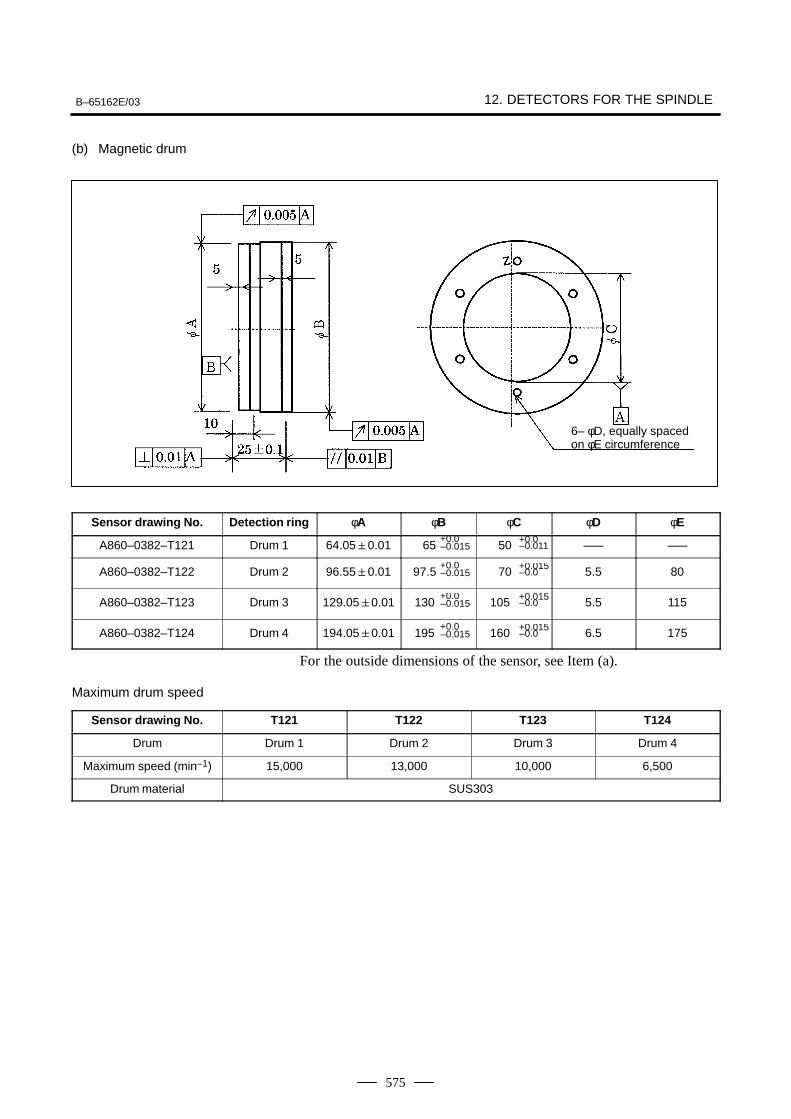
B–65162E/03 12. DETECTORS FOR THE SPINDLE
575
(b) Magnetic drum
6– φD, equally spacedon φE circumference
Sensor drawing No. Detection ring φA φB φC φD φE
A860–0382–T121 Drum 1 64.050.01 65+0.0–0.015 50 +0.0
–0.011 ––– –––
A860–0382–T122 Drum 2 96.550.01 97.5+0.0–0.015 70 +0.015
–0.0 5.5 80
A860–0382–T123 Drum 3 129.050.01 130+0.0–0.015 105 +0.015
–0.0 5.5 115
A860–0382–T124 Drum 4 194.050.01 195+0.0–0.015 160 +0.015
–0.0 6.5 175
For the outside dimensions of the sensor, see Item (a).
Maximum drum speed
Sensor drawing No. T121 T122 T123 T124
Drum Drum 1 Drum 2 Drum 3 Drum 4
Maximum speed (min–1) 15,000 13,000 10,000 6,500
Drum material SUS303
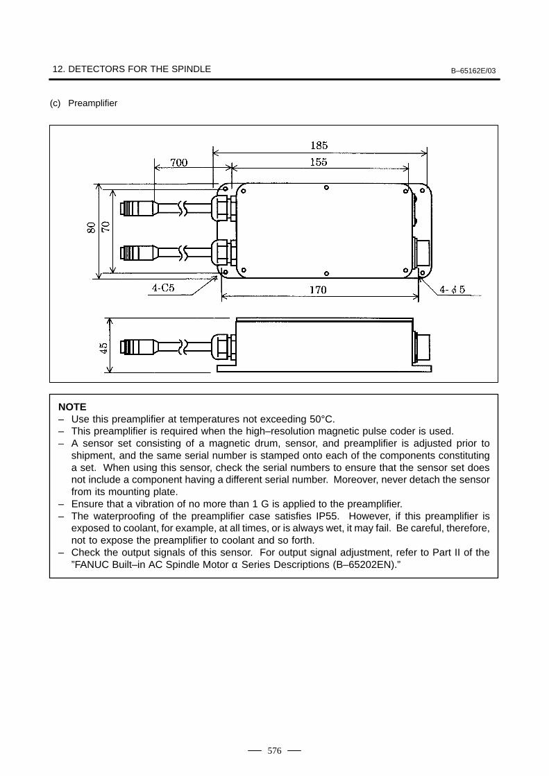
12. DETECTORS FOR THE SPINDLE B–65162E/03
576
(c) Preamplifier
NOTE– Use this preamplifier at temperatures not exceeding 50°C.– This preamplifier is required when the high–resolution magnetic pulse coder is used.– A sensor set consisting of a magnetic drum, sensor, and preamplifier is adjusted prior to
shipment, and the same serial number is stamped onto each of the components constitutinga set. When using this sensor, check the serial numbers to ensure that the sensor set doesnot include a component having a different serial number. Moreover, never detach the sensorfrom its mounting plate.
– Ensure that a vibration of no more than 1 G is applied to the preamplifier.– The waterproofing of the preamplifier case satisfies IP55. However, if this preamplifier is
exposed to coolant, for example, at all times, or is always wet, it may fail. Be careful, therefore,not to expose the preamplifier to coolant and so forth.
– Check the output signals of this sensor. For output signal adjustment, refer to Part II of the”FANUC Built–in AC Spindle Motor α Series Descriptions (B–65202EN).”
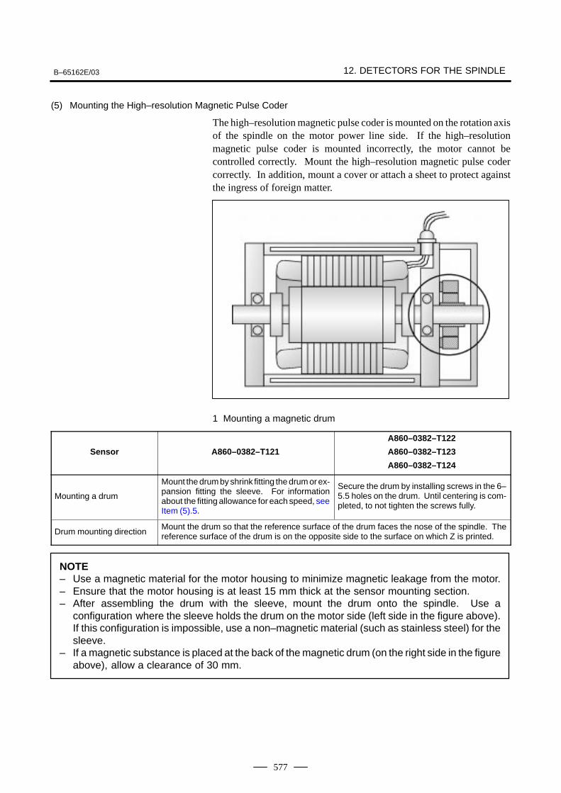
B–65162E/03 12. DETECTORS FOR THE SPINDLE
577
(5) Mounting the High–resolution Magnetic Pulse Coder
The high–resolution magnetic pulse coder is mounted on the rotation axisof the spindle on the motor power line side. If the high–resolutionmagnetic pulse coder is mounted incorrectly, the motor cannot becontrolled correctly. Mount the high–resolution magnetic pulse codercorrectly. In addition, mount a cover or attach a sheet to protect againstthe ingress of foreign matter.
1 Mounting a magnetic drum
Sensor A860–0382–T121
A860–0382–T122
A860–0382–T123
A860–0382–T124
Mounting a drum
Mount the drum by shrink fitting the drum or ex-pansion fitting the sleeve. For informationabout the fitting allowance for each speed, seeItem (5).5.
Secure the drum by installing screws in the 6–5.5 holes on the drum. Until centering is com-pleted, to not tighten the screws fully.
Drum mounting directionMount the drum so that the reference surface of the drum faces the nose of the spindle. Thereference surface of the drum is on the opposite side to the surface on which Z is printed.
NOTE– Use a magnetic material for the motor housing to minimize magnetic leakage from the motor.– Ensure that the motor housing is at least 15 mm thick at the sensor mounting section.– After assembling the drum with the sleeve, mount the drum onto the spindle. Use a
configuration where the sleeve holds the drum on the motor side (left side in the figure above).If this configuration is impossible, use a non–magnetic material (such as stainless steel) for thesleeve.
– If a magnetic substance is placed at the back of the magnetic drum (on the right side in the figureabove), allow a clearance of 30 mm.
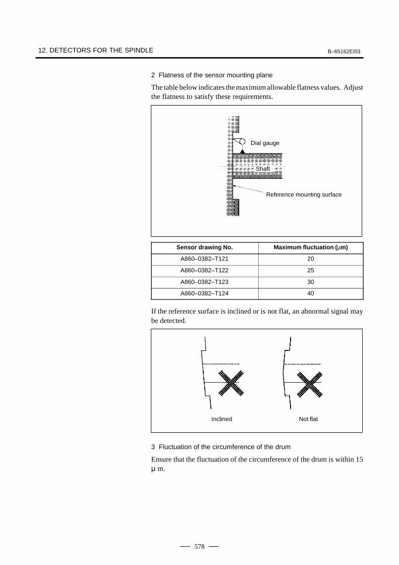
12. DETECTORS FOR THE SPINDLE B–65162E/03
578
2 Flatness of the sensor mounting plane
The table below indicates the maximum allowable flatness values. Adjustthe flatness to satisfy these requirements.
Dial gauge
Shaft
Reference mounting surface
Sensor drawing No. Maximum fluctuation ( µm)
A860–0382–T121 20
A860–0382–T122 25
A860–0382–T123 30
A860–0382–T124 40
If the reference surface is inclined or is not flat, an abnormal signal maybe detected.
Inclined Not flat
3 Fluctuation of the circumference of the drum
Ensure that the fluctuation of the circumference of the drum is within 15µ m.
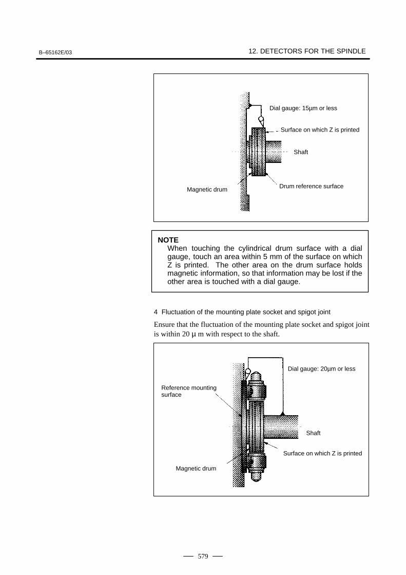
B–65162E/03 12. DETECTORS FOR THE SPINDLE
579
Dial gauge: 15µm or less
Surface on which Z is printed
Shaft
Drum reference surfaceMagnetic drum
NOTEWhen touching the cylindrical drum surface with a dialgauge, touch an area within 5 mm of the surface on whichZ is printed. The other area on the drum surface holdsmagnetic information, so that information may be lost if theother area is touched with a dial gauge.
4 Fluctuation of the mounting plate socket and spigot joint
Ensure that the fluctuation of the mounting plate socket and spigot jointis within 20 µ m with respect to the shaft.
Dial gauge: 20µm or less
Shaft
Magnetic drum
Reference mountingsurface
Surface on which Z is printed
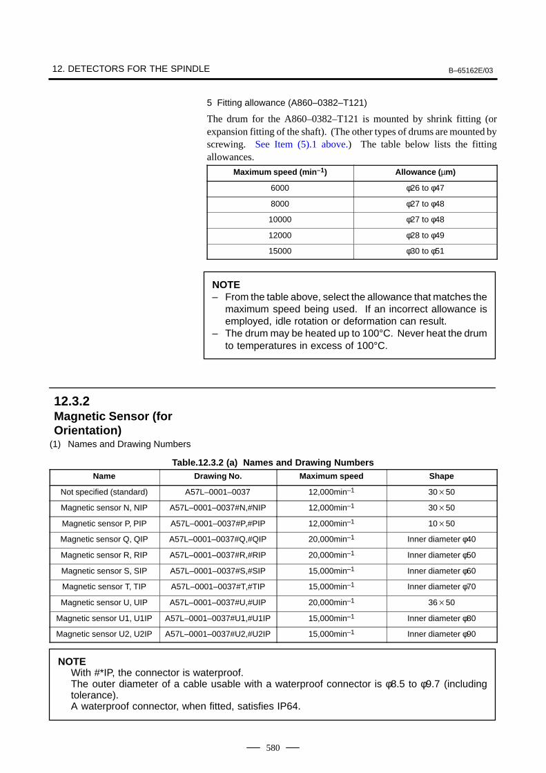
12. DETECTORS FOR THE SPINDLE B–65162E/03
580
5 Fitting allowance (A860–0382–T121)
The drum for the A860–0382–T121 is mounted by shrink fitting (orexpansion fitting of the shaft). (The other types of drums are mounted byscrewing. See Item (5).1 above.) The table below lists the fittingallowances.
Maximum speed (min –1) Allowance ( µm)
6000 φ26 to φ47
8000 φ27 to φ48
10000 φ27 to φ48
12000 φ28 to φ49
15000 φ30 to φ51
NOTE– From the table above, select the allowance that matches the
maximum speed being used. If an incorrect allowance isemployed, idle rotation or deformation can result.
– The drum may be heated up to 100°C. Never heat the drumto temperatures in excess of 100°C.
(1) Names and Drawing Numbers
Table.12.3.2 (a) Names and Drawing NumbersName Drawing No. Maximum speed Shape
Not specified (standard) A57L–0001–0037 12,000min–1 3050
Magnetic sensor N, NIP A57L–0001–0037#N,#NIP 12,000min–1 3050
Magnetic sensor P, PIP A57L–0001–0037#P,#PIP 12,000min–1 1050
Magnetic sensor Q, QIP A57L–0001–0037#Q,#QIP 20,000min–1 Inner diameter φ40
Magnetic sensor R, RIP A57L–0001–0037#R,#RIP 20,000min–1 Inner diameter φ50
Magnetic sensor S, SIP A57L–0001–0037#S,#SIP 15,000min–1 Inner diameter φ60
Magnetic sensor T, TIP A57L–0001–0037#T,#TIP 15,000min–1 Inner diameter φ70
Magnetic sensor U, UIP A57L–0001–0037#U,#UIP 20,000min–1 3650
Magnetic sensor U1, U1IP A57L–0001–0037#U1,#U1IP 15,000min–1 Inner diameter φ80
Magnetic sensor U2, U2IP A57L–0001–0037#U2,#U2IP 15,000min–1 Inner diameter φ90
NOTEWith #*IP, the connector is waterproof. The outer diameter of a cable usable with a waterproof connector is φ8.5 to φ9.7 (includingtolerance).A waterproof connector, when fitted, satisfies IP64.
12.3.2Magnetic Sensor (forOrientation)
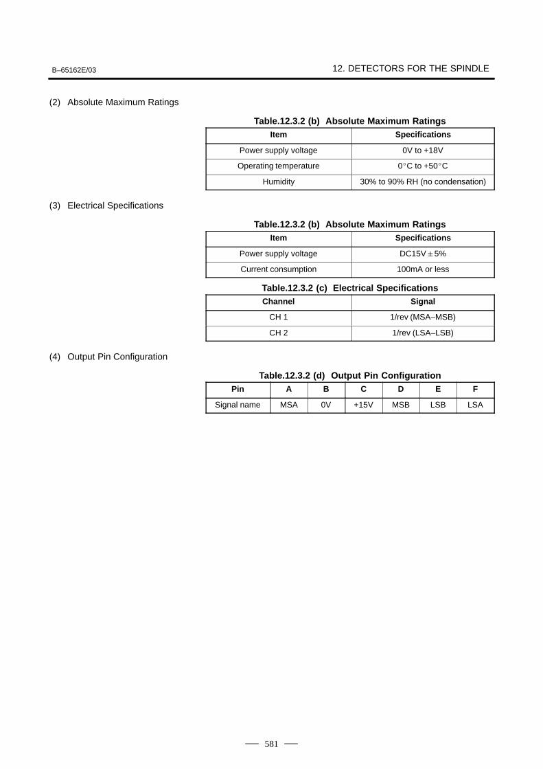
B–65162E/03 12. DETECTORS FOR THE SPINDLE
581
(2) Absolute Maximum Ratings
Table.12.3.2 (b) Absolute Maximum RatingsItem Specifications
Power supply voltage 0V to +18V
Operating temperature 0C to +50C
Humidity 30% to 90% RH (no condensation)
(3) Electrical Specifications
Table.12.3.2 (b) Absolute Maximum RatingsItem Specifications
Power supply voltage DC15V5%
Current consumption 100mA or less
Table.12.3.2 (c) Electrical SpecificationsChannel Signal
CH 1 1/rev (MSA–MSB)
CH 2 1/rev (LSA–LSB)
(4) Output Pin Configuration
Table.12.3.2 (d) Output Pin ConfigurationPin A B C D E F
Signal name MSA 0V +15V MSB LSB LSA
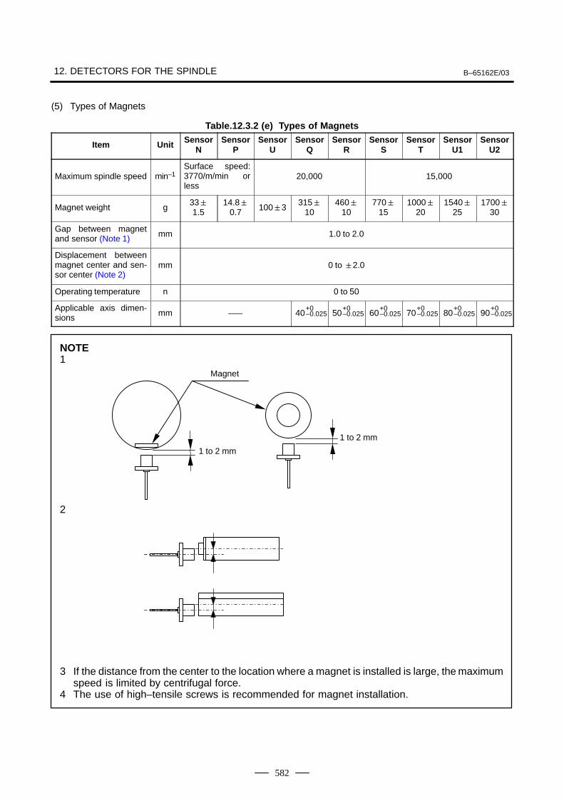
12. DETECTORS FOR THE SPINDLE B–65162E/03
582
(5) Types of Magnets
Table.12.3.2 (e) Types of Magnets
Item Unit SensorN
SensorP
SensorU
SensorQ
SensorR
SensorS
SensorT
SensorU1
SensorU2
Maximum spindle speed min–1Surface speed:3770/m/min orless
20,000 15,000
Magnet weight g331.5
14.80.7 1003
31510
46010
77015
100020
154025
170030
Gap between magnetand sensor (Note 1) mm 1.0 to 2.0
Displacement betweenmagnet center and sen-sor center (Note 2)
mm 0 to 2.0
Operating temperature n 0 to 50
Applicable axis dimen-sions mm ––– 40
+0–0.025 50
+0–0.025 60
+0–0.025 70
+0–0.025 80
+0–0.025 90
+0–0.025
NOTE1
2
3 If the distance from the center to the location where a magnet is installed is large, the maximumspeed is limited by centrifugal force.
4 The use of high–tensile screws is recommended for magnet installation.
Magnet
1 to 2 mm
1 to 2 mm
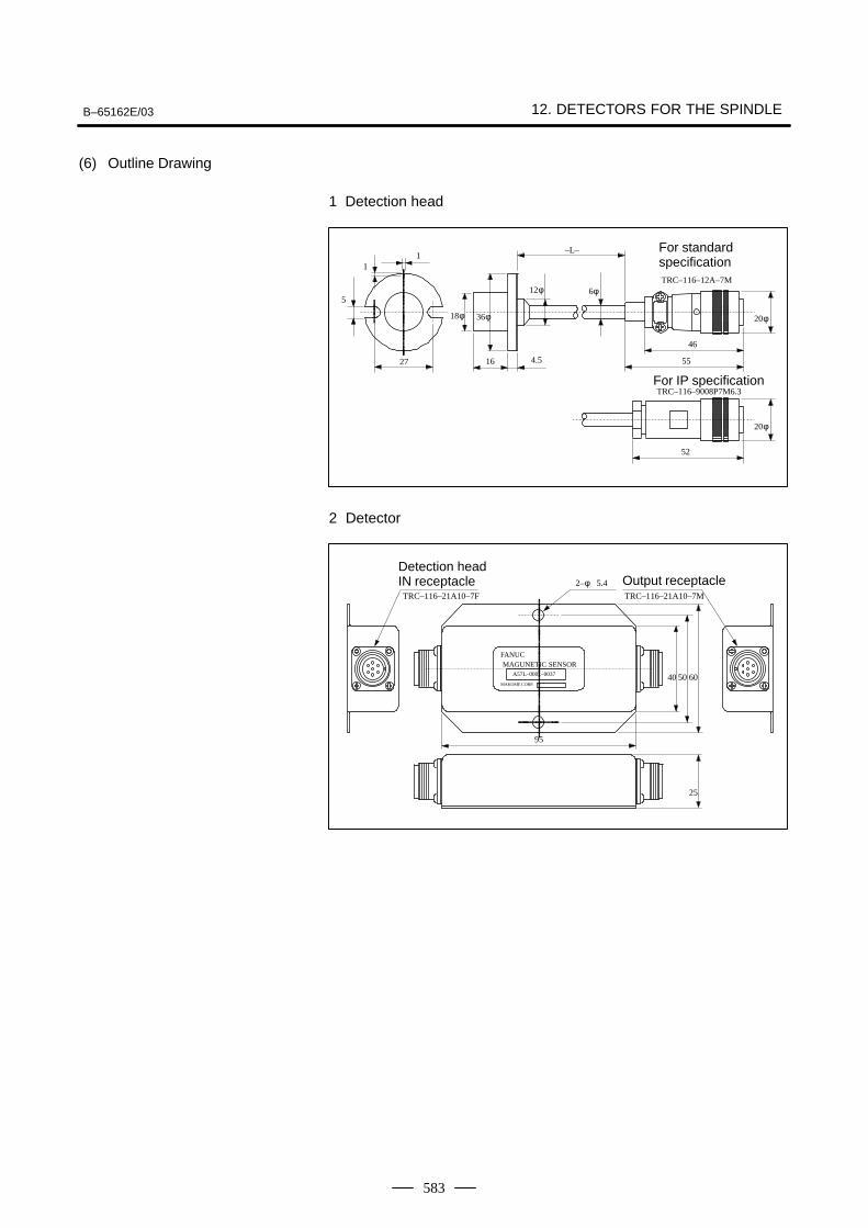
B–65162E/03 12. DETECTORS FOR THE SPINDLE
583
(6) Outline Drawing
1 Detection head
20φ
6φ12φ
36φ18φ
1
5
–L–
4.5 55
TRC–116–9008P7M6.3
46
TRC–116–12A–7M
1627
1
20φ
52
For standardspecification
For IP specification
2 Detector
25
605040
TRC–116–21A10–7M
MAKOME CORP.
A57L–0001–0037
FANUC MAGUNETIC SENSOR
95
2–φ 5.4
TRC–116–21A10–7F
Detection headIN receptacle Output receptacle
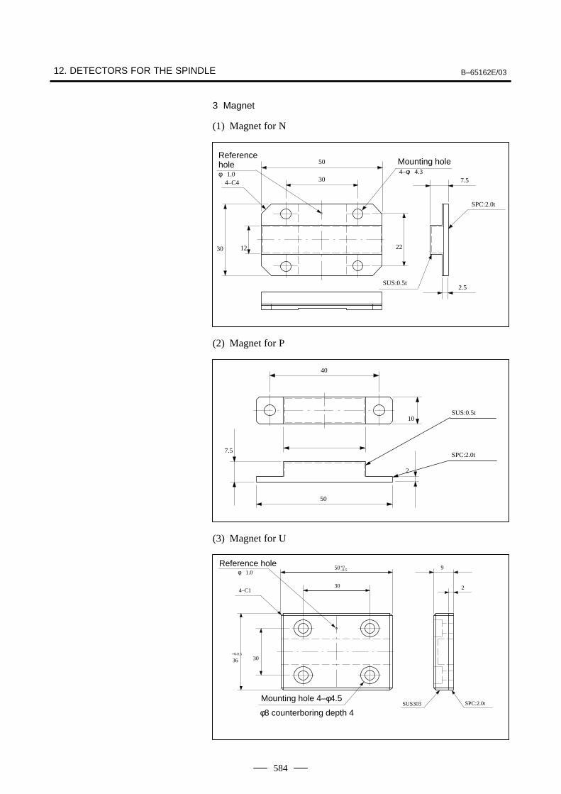
12. DETECTORS FOR THE SPINDLE B–65162E/03
584
3 Magnet
(1) Magnet for N
SUS:0.5t
SPC:2.0t
2.5
7.54–φ 4.3φ 1.0
4–C4
30 12 22
30
50Referencehole Mounting hole
(2) Magnet for P
40
SPC:2.0t
SUS:0.5t
7.5
2
10
50
(3) Magnet for U
SPC:2.0tSUS303
φ 1.0
4–C1
9
2
–0.5
–0.5
36+0
30
30
50+0Reference hole
Mounting hole 4–φ4.5
φ8 counterboring depth 4
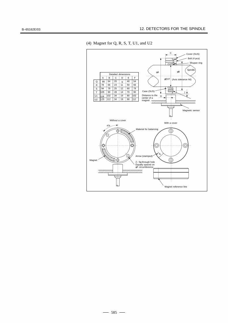
B–65162E/03 12. DETECTORS FOR THE SPINDLE
585
(4) Magnet for Q, R, S, T, U1, and U2
A B C D E F
Q 66 54 20 9 40 54
R 78 66 23 11 50 66
S 94 79 25 12 60 79
T 105 90 28 14 70 90
U1 118 102 34 19 80 102
U2 125 112 34 19 90 112
C
φEH7
φA
2
D
45k
Detailed dimensions
Cover (SUS)
Bolt (4 pcs)
Shupan ring
SpindleφB
(Axis tolerance h6)
Case (SUS)
Distance to thecenter of amagnet
Magnet
Magnetic sensor
Without a coverWith a cover
Material for balancing
Arrow (stamped)
2– 5φ through holeEqually spaced on φF circumference
Magnet reference line
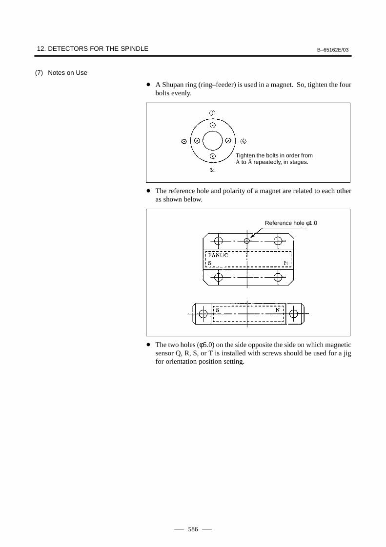
12. DETECTORS FOR THE SPINDLE B–65162E/03
586
(7) Notes on Use
A Shupan ring (ring–feeder) is used in a magnet. So, tighten the fourbolts evenly.
Tighten the bolts in order fromÀ to à repeatedly, in stages.
The reference hole and polarity of a magnet are related to each otheras shown below.
Reference hole φ1.0
The two holes (φ5.0) on the side opposite the side on which magneticsensor Q, R, S, or T is installed with screws should be used for a jigfor orientation position setting.
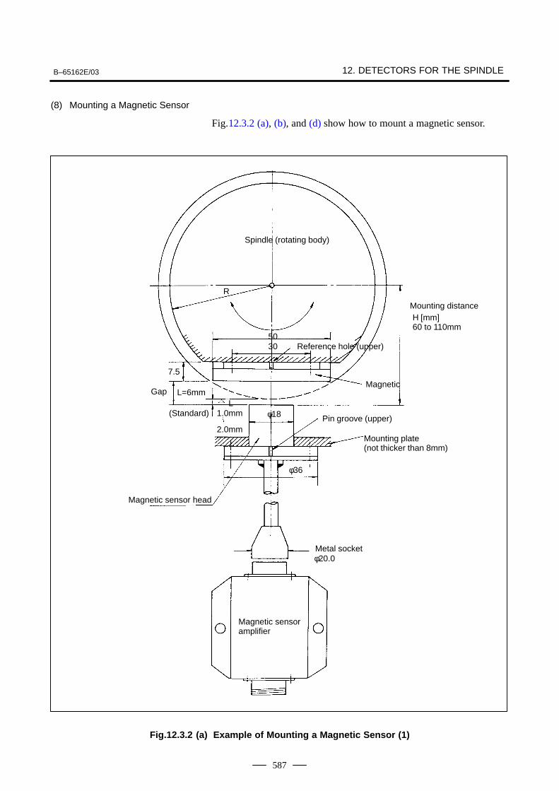
B–65162E/03 12. DETECTORS FOR THE SPINDLE
587
(8) Mounting a Magnetic Sensor
Fig.12.3.2 (a), (b), and (d) show how to mount a magnetic sensor.
Spindle (rotating body)
R
Reference hole (upper)5030
7.5
L=6mm
Mounting distanceH [mm]60 to 110mm
GapMagnetic
(Standard) 1.0mm
2.0mm
L
Pin groove (upper)
Mounting plate (not thicker than 8mm)
φ36
φ18
φ20.0
Magnetic sensor head
Metal socket
Magnetic sensoramplifier
Fig.12.3.2 (a) Example of Mounting a Magnetic Sensor (1)
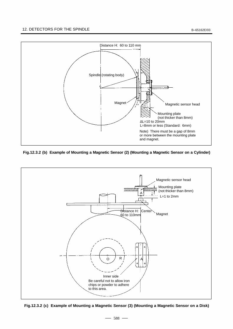
12. DETECTORS FOR THE SPINDLE B–65162E/03
588
Distance H: 60 to 110 mm
Spindle (rotating body)
Magnet Magnetic sensor head
Mounting plate (not thicker than 8mm)
∆L=10 to 20mmL=8mm or less (Standard: 6mm)
Note) There must be a gap of 8mmor more between the mounting plateand magnet.
Fig.12.3.2 (b) Example of M ounting a Magnetic Sensor (2) (Mounting a Magnetic Sensor on a Cylinder)
Magnetic sensor head
Mounting plate (not thicker than 8mm)
L=1 to 2mm
Distance H: 60 to 110mm
CenterMagnet
Inner sideBe careful not to allow ironchips or powder to adhereto this area.
O R A
A
Fig.12.3.2 (c) Example of Mounting a Magnetic Sensor (3) (Mounting a Magnetic Sensor on a Disk)
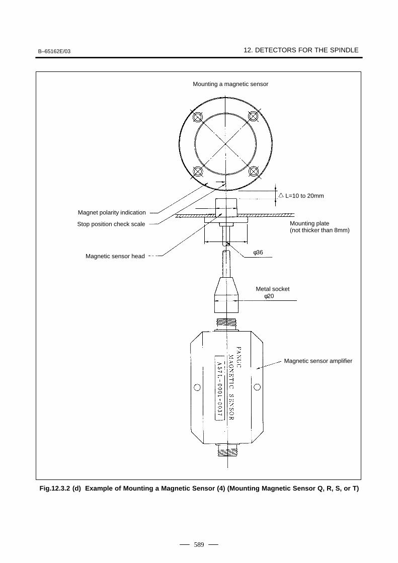
B–65162E/03 12. DETECTORS FOR THE SPINDLE
589
Mounting a magnetic sensor
L=10 to 20mm
φ20
φ36
Magnet polarity indication
Stop position check scale Mounting plate (not thicker than 8mm)
Magnetic sensor head
Metal socket
Magnetic sensor amplifier
Fig.12.3.2 (d) Example of Mounting a Magnetic Sensor (4) (Mounting Magnetic Sensor Q, R, S, or T)
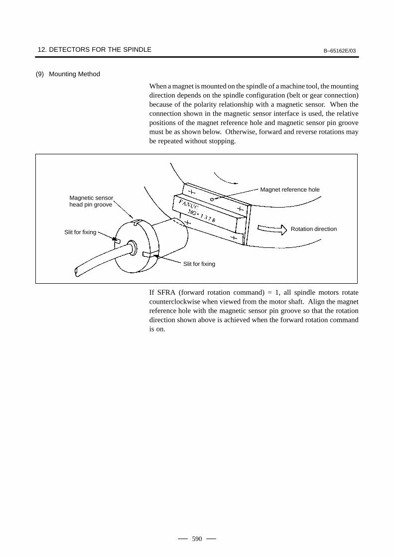
12. DETECTORS FOR THE SPINDLE B–65162E/03
590
(9) Mounting Method
When a magnet is mounted on the spindle of a machine tool, the mountingdirection depends on the spindle configuration (belt or gear connection)because of the polarity relationship with a magnetic sensor. When theconnection shown in the magnetic sensor interface is used, the relativepositions of the magnet reference hole and magnetic sensor pin groovemust be as shown below. Otherwise, forward and reverse rotations maybe repeated without stopping.
Magnet reference holeMagnetic sensorhead pin groove
Rotation direction
Slit for fixing
Slit for fixing
If SFRA (forward rotation command) = 1, all spindle motors rotatecounterclockwise when viewed from the motor shaft. Align the magnetreference hole with the magnetic sensor pin groove so that the rotationdirection shown above is achieved when the forward rotation commandis on.
B–65162E/03 12. DETECTORS FOR THE SPINDLE
591
(10) Notes on Mounting a Magnetic Sensor
(a) A magnetic sensor is mounted on the rotation body of the spindle.So, ensure that a magnet is not dislodged by centrifugal force. Thesurface speed of a magnet should not exceed 3770 m/min. (N and Ptypes)
(b) Mount a magnetic sensor amplifier as close to the sensor as possible.
(c) Never allow a magnetic substance to come close to the magneticsensor. (Otherwise, the stop position may change.) In particular,never place a magnetic device such as a solenoid near the magnet.
(d) Be careful not to allow iron chips or powder to adhere to the magnet.
(e) If the spindle contains a circuit such as a magnetic clutch for high/lowswitching that forms a magnetic loop, mount a magnet on anon–magnetic (such as aluminum) plate. The magnetic flux of themagnet at a stop position is zero. However, if the magnetic loop ofa magnetic clutch has an influence, a magnetic flux is always appliedwhen the magnetic clutch is on. Note that if the magnetic clutch isturned on and off at a stop position, the stable magnetic flux changes,thus causing the stop position to change.
(f) Pay careful attention to the configuration so that the cable side of themagnetic sensor head, magnetic sensor amplifier, and connectioncables are not exposed to lubricant or coolant.
(g) Mount the magnet of a magnetic sensor directly on the spindle. If amagnet is mounted by means of a gear connection or splineconnection, the repeatability degrades, depending on the amount ofbacklash between the spindle and magnet. For improvedrepeatability, also consider deterioration with age (such asmechanical wear).
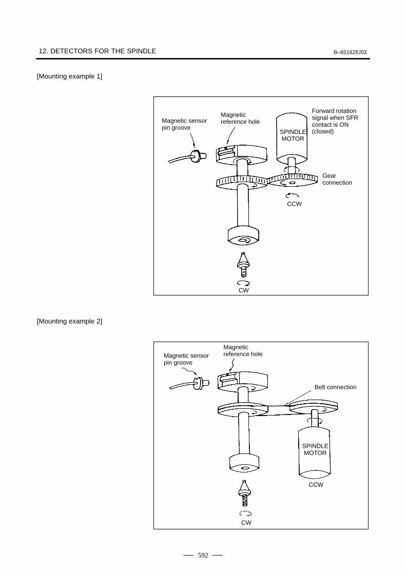
12. DETECTORS FOR THE SPINDLE B–65162E/03
592
[Mounting example 1]
Magnetic sensorpin groove
Magnetic reference hole
Forward rotationsignal when SFRcontact is ON(closed)
Gear connection
CCW
CW
SPINDLEMOTOR
[Mounting example 2]
Magnetic sensorpin groove
Magnetic reference hole
CCW
CW
SPINDLEMOTOR
Belt connection
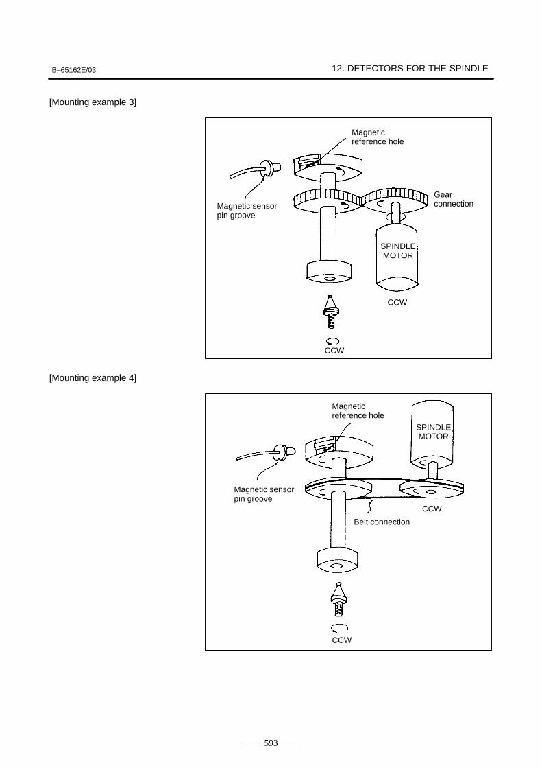
B–65162E/03 12. DETECTORS FOR THE SPINDLE
593
[Mounting example 3]
Magnetic sensorpin groove
Gear connection
CCW
SPINDLEMOTOR
CCW
Magnetic reference hole
[Mounting example 4]
Magnetic sensorpin groove
Magnetic reference hole
CCW
SPINDLEMOTOR
Belt connection
CCW
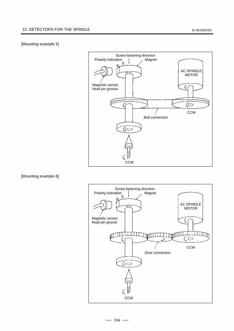
12. DETECTORS FOR THE SPINDLE B–65162E/03
594
[Mounting example 5]
Magnetic sensorhead pin groove
Polarity indication
NS
Screw fastening directionMagnet
AC SPINDLEMOTOR
Belt connectionCCW
CCW
[Mounting example 6]
Magnetic sensorhead pin groove
Polarity indication
NS
Screw fastening directionMagnet
AC SPINDLEMOTOR
CCW
CCW
Gear connection

APPENDIX

A. FITTING A LIGHTNING SURGEPROTECTION DEVICE B–65162E/03APPENDIX
596
A FITTING A LIGHTNING SURGE PROTECTION DEVICE
This appendix describes how to install a lightning surge protector andprovides notes on installation. For information about the lightning surgeprotector recommended by FANUC, see Section 8.1.11.
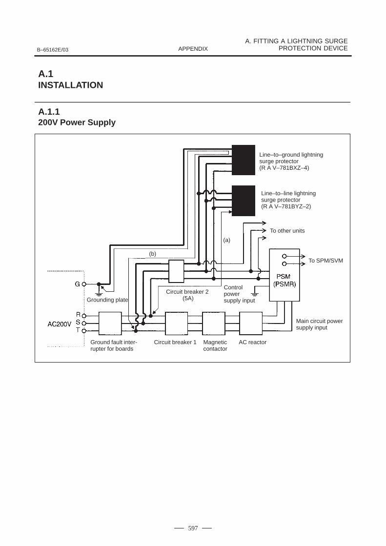
B–65162E/03
A. FITTING A LIGHTNING SURGEPROTECTION DEVICEAPPENDIX
597
Line–to–ground lightningsurge protector (R A V–781BXZ–4)
Line–to–line lightningsurge protector (R A V–781BYZ–2)
To other units
To SPM/SVM
Grounding plateCircuit breaker 2
(5A)
Controlpower supply input
Ground fault inter-rupter for boards
Circuit breaker 1 Magneticcontactor
AC reactor
Main circuit powersupply input
(a)
(b)
A.1INSTALLATION
A.1.1200V Power Supply
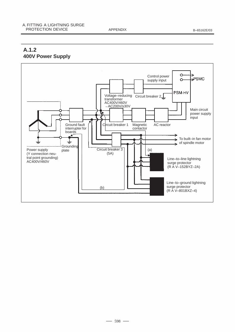
A. FITTING A LIGHTNING SURGEPROTECTION DEVICE B–65162E/03APPENDIX
598
Control powersupply input
Voltage–reducingtransformerAC400V/460V→AC200V/s30V
Circuit breaker 2
Main circuitpower supplyinput
Ground faultinterrupter forboards
Circuit breaker 1 Magneticcontactor
AC reactor
To built–in fan motorof spindle motor
GroundingplatePower supply
(Y connection neu-tral point grounding)AC400V/460V
Circuit breaker 3 (5A)
Line–to–line lightningsurge protector (R A V–152BYZ–2A)
Line–to–ground lightningsurge protector (R A V–801BXZ–4)
(a)
(b)
A.1.2400V Power Supply
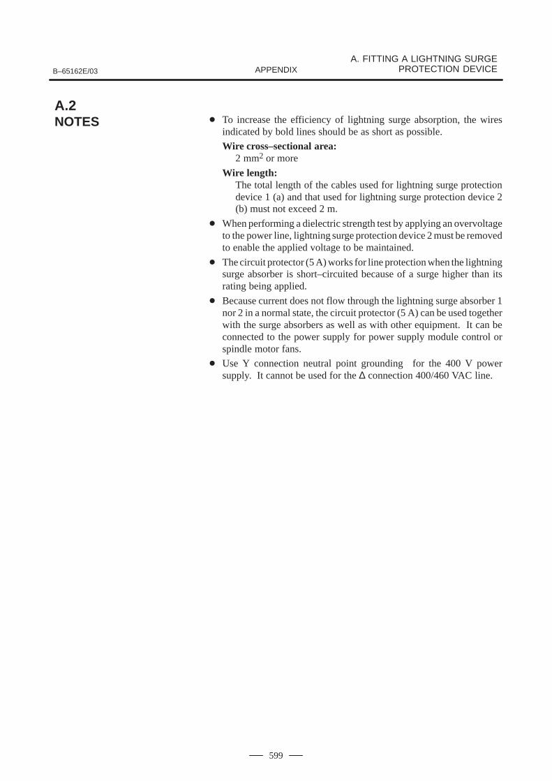
B–65162E/03
A. FITTING A LIGHTNING SURGEPROTECTION DEVICEAPPENDIX
599
To increase the efficiency of lightning surge absorption, the wiresindicated by bold lines should be as short as possible.
Wire cross–sectional area:2 mm2 or more
Wire length:The total length of the cables used for lightning surge protectiondevice 1 (a) and that used for lightning surge protection device 2(b) must not exceed 2 m.
When performing a dielectric strength test by applying an overvoltageto the power line, lightning surge protection device 2 must be removedto enable the applied voltage to be maintained.
The circuit protector (5 A) works for line protection when the lightningsurge absorber is short–circuited because of a surge higher than itsrating being applied.
Because current does not flow through the lightning surge absorber 1nor 2 in a normal state, the circuit protector (5 A) can be used togetherwith the surge absorbers as well as with other equipment. It can beconnected to the power supply for power supply module control orspindle motor fans.
Use Y connection neutral point grounding for the 400 V powersupply. It cannot be used for the ∆ connection 400/460 VAC line.
A.2NOTES
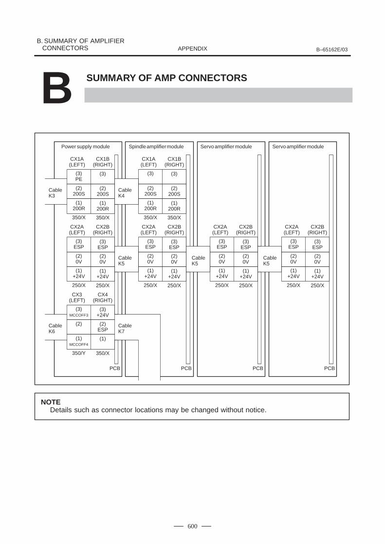
B. SUMMARY OF AMPLIFIER CONNECTORS B–65162E/03APPENDIX
600
B SUMMARY OF AMP CONNECTORS
CX1A(LEFT)
CableK4
Power supply module
CX1B(RIGHT)
(3)PE
(3)
(2)200S
(2)200S
(1)200R
(1)200R
350/X 350/X
CX2A(LEFT)
CX2B(RIGHT)
(3)ESP
(3)ESP
(2)0V
(2)0V
(1)+24V
(1)+24V
250/X 250/X
CX1A(LEFT)
CX1B(RIGHT)
(3) (3)
(2)200S
(2)200S
(1)200R
(1)200R
350/X 350/X
CX2A(LEFT)
CX2B(RIGHT)
(3)ESP
(3)ESP
(2)0V
(2)0V
(1)+24V
(1)+24V
250/X 250/X
CX3(LEFT)
CX4(RIGHT)
(3)MCCOFF3
(3)+24V
(2) (2)ESP
(1)MCCOFF4
(1)
350/Y 350/X
PCB PCB
Spindle amplifier module Servo amplifier module Servo amplifier module
CX2A(LEFT)
CX2B(RIGHT)
(3)ESP
(3)ESP
(2)0V
(2)0V
(1)+24V
(1)+24V
250/X 250/X
PCB
CX2A(LEFT)
CX2B(RIGHT)
(3)ESP
(3)ESP
(2)0V
(2)0V
(1)+24V
(1)+24V
250/X 250/X
PCB
CableK5
CableK6
CableK7
CableK5
CableK5
CableK3
NOTEDetails such as connector locations may be changed without notice.
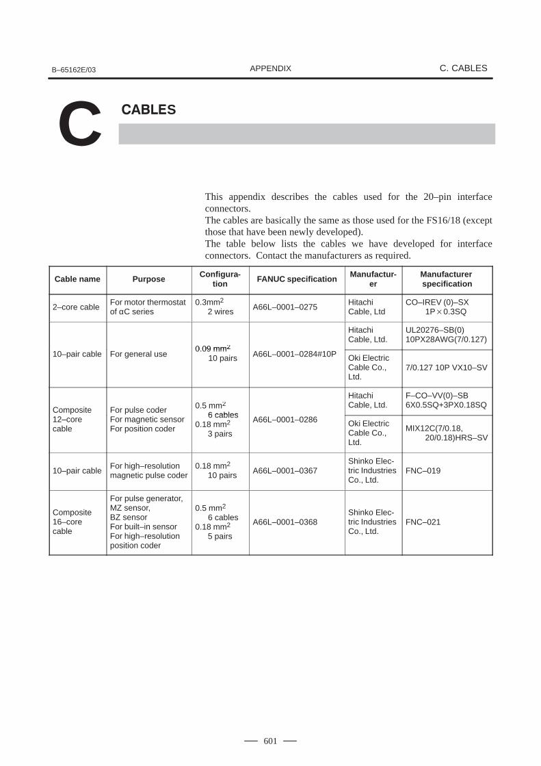
B–65162E/03 C. CABLESAPPENDIX
601
C S
This appendix describes the cables used for the 20–pin interfaceconnectors.The cables are basically the same as those used for the FS16/18 (exceptthose that have been newly developed).The table below lists the cables we have developed for interfaceconnectors. Contact the manufacturers as required.
Cable name Purpose Configura-tion FANUC specification Manufactur-
erManufacturer specification
2–core cableFor motor thermostatof αC series
0.3mm2
2 wires A66L–0001–0275HitachiCable, Ltd
CO–IREV (0)–SX 1P0.3SQ
0 09 mm2
HitachiCable, Ltd.
UL20276–SB(0)10PX28AWG(7/0.127)
10–pair cable For general use0.09 mm2
10 pairs A66L–0001–0284#10P Oki ElectricCable Co.,Ltd.
7/0.127 10P VX10–SV
Composite For pulse coder 0.5 mm2
6 cables
HitachiCable, Ltd.
F–CO–VV(0)–SB6X0.5SQ+3PX0.18SQ
Com osite12–corecable
For ulse coderFor magnetic sensorFor position coder
6 cables0.18 mm2
3 pairs
A66L–0001–0286 Oki ElectricCable Co.,Ltd.
MIX12C(7/0.18, 20/0.18)HRS–SV
10–pair cableFor high–resolutionmagnetic pulse coder
0.18 mm2
10 pairs A66L–0001–0367Shinko Elec-tric IndustriesCo., Ltd.
FNC–019
Composite16–corecable
For pulse generator, MZ sensor, BZ sensorFor built–in sensorFor high–resolutionposition coder
0.5 mm2
6 cables0.18 mm2
5 pairs
A66L–0001–0368Shinko Elec-tric IndustriesCo., Ltd.
FNC–021
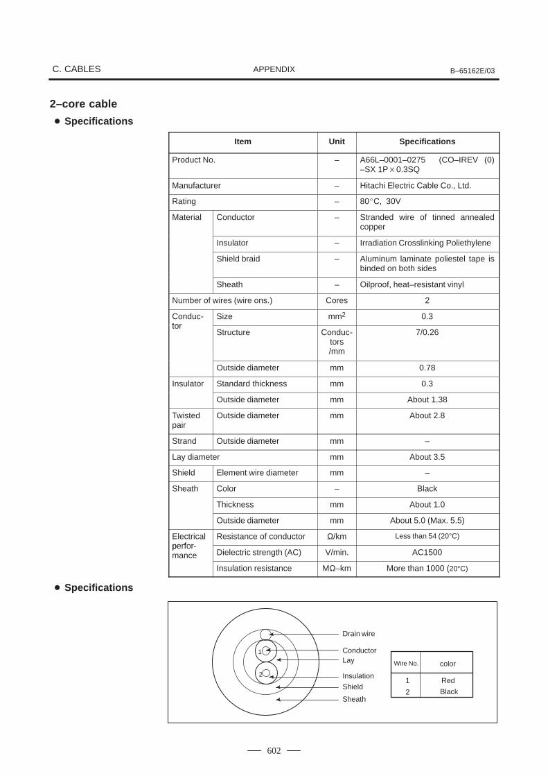
C. CABLES B–65162E/03APPENDIX
602
2–core cable
Item Unit Specifications
Product No. – A66L–0001–0275 (CO–IREV (0)–SX 1P0.3SQ
Manufacturer – Hitachi Electric Cable Co., Ltd.
Rating – 80C, 30V
Material Conductor – Stranded wire of tinned annealedcopper
Insulator – Irradiation Crosslinking Poliethylene
Shield braid – Aluminum laminate poliestel tape isbinded on both sides
Sheath – Oilproof, heat–resistant vinyl
Number of wires (wire ons.) Cores 2
Conduc-tor
Size mm2 0.3tor
Structure Conduc-tors/mm
7/0.26
Outside diameter mm 0.78
Insulator Standard thickness mm 0.3
Outside diameter mm About 1.38
Twistedpair
Outside diameter mm About 2.8
Strand Outside diameter mm –
Lay diameter mm About 3.5
Shield Element wire diameter mm –
Sheath Color – Black
Thickness mm About 1.0
Outside diameter mm About 5.0 (Max. 5.5)
Electricalperfor
Resistance of conductor Ω/km Less than 54 (20°C)perfor-mance Dielectric strength (AC) V/min. AC1500
Insulation resistance MΩ–km More than 1000 (20°C)
1
2
Wire No. color
1
2
Red
Black
Drain wire
Conductor
Insulation
Shield
Sheath
Lay
Specifications
Specifications
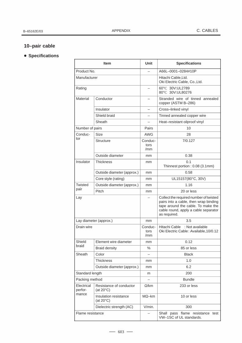
B–65162E/03 C. CABLESAPPENDIX
603
Item Unit Specifications
Product No. – A66L–0001–0284#10P
Manufacturer Hitachi Cable,Ltd.Oki Electric Cable, Co.,Ltd.
Rating – 60°C 30V:UL278980°C 30V:UL80276
Material Conductor – Stranded wire of tinned annealedcopper (ASTM B–286)
Insulator – Cross–linked vinyl
Shield braid – Tinned annealed copper wire
Sheath – Heat–resistant oilproof vinyl
Number of pairs Pairs 10
Conduc-tor
Size AWG 28tor
Structure Conduc-tors/mm
7/0.127
Outside diameter mm 0.38
Insulator Thickness mm 0.1Thinnest portion : 0.08 (3.1mm)
Outside diameter (approx.) mm 0.58
Core style (rating) mm UL15157(80°C, 30V)
Twistedpair
Outside diameter (approx.) mm 1.16pair
Pitch mm 20 or less
Lay – Collect the required number of twistedpairs into a cable, then wrap bindingtape around the cable. To make thecable round, apply a cable separatoras required.
Lay diameter (approx.) mm 3.5
Drain wire Conduc-tors/mm
Hitachi Cable : Not availableOki Electric Cable: Available,10/0.12
Shieldbraid
Element wire diameter mm 0.12braid
Braid density % 85 or less
Sheath Color – Black
Thickness mm 1.0
Outside diameter (approx.) mm 6.2
Standard length m 200
Packing method – Bundle
Electricalperfor-mance
Resistance of conductor(at 20°C)
Ω/km 233 or less
manceInsulation resistance (at 20°C)
MΩ–km 10 or less
Dielectric strength (AC) V/min. 300
Flame resistance – Shall pass flame resistance testVW–1SC of UL standards.
10–pair cable
Specifications
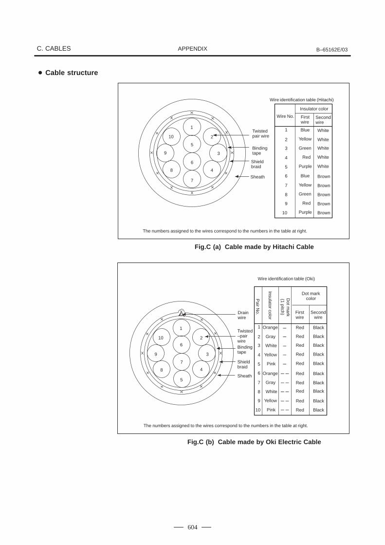
C. CABLES B–65162E/03APPENDIX
604
1
2
3
4
5
6
7
8
9
10
Wire identification table (Hitachi)
Wire No.
Insulator color
First wire
Secondwire
1
2
3
4
5
6
7
8
10
9
Blue
Yellow
Green
Red
Purple
Blue
Yellow
Green
Red
Purple
White
Brown
Twistedpair wire
Bindingtape
Shieldbraid
Sheath
The numbers assigned to the wires correspond to the numbers in the table at right.
White
White
White
White
Brown
Brown
Brown
Brown
Fig.C (a) Cable made by Hitachi Cable
Dot markcolor
Wire identification table (Oki)
1
2
3
4
5
6
7
8
10
9
Orange
Gray
White
Yellow
Pink
Orange
Gray
White
Yellow
Pink
Red
Firstwire
Secondwire
Black
Drain wire
Twisted–pairwireBinding tape
Shield braid
Sheath
The numbers assigned to the wires correspond to the numbers in the table at right.
1
2
3
4
5
6
7
8
9
10 Red
Red
Red
Red
Red
Red
Red
Red
Red
Black
Black
Black
Black
Black
Black
Black
Black
Black
Pair N
o.
Insulator color
Dot m
ark(1 pitch)
Fig.C (b) Cable made by Oki Electric Cable
Cable structure
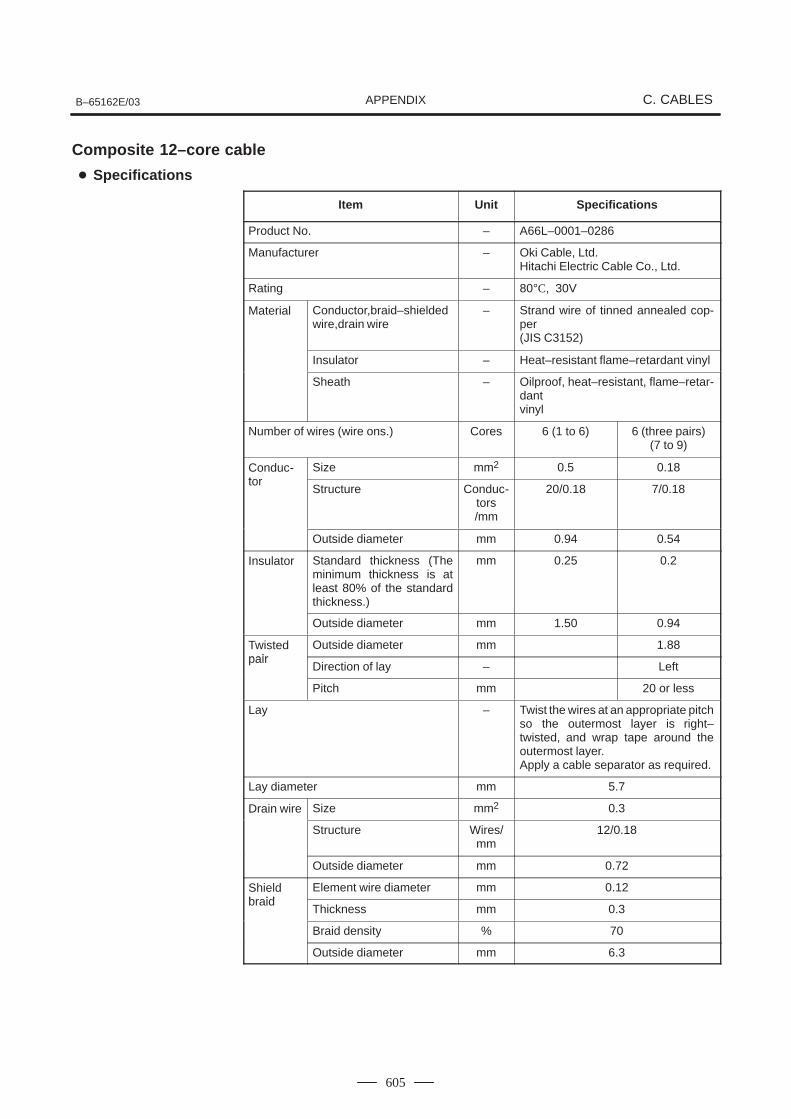
B–65162E/03 C. CABLESAPPENDIX
605
Composite 12–core cable
Item Unit Specifications
Product No. – A66L–0001–0286
Manufacturer – Oki Cable, Ltd.Hitachi Electric Cable Co., Ltd.
Rating – 80°C, 30V
Material Conductor,braid–shieldedwire,drain wire
– Strand wire of tinned annealed cop-per(JIS C3152)
Insulator – Heat–resistant flame–retardant vinyl
Sheath – Oilproof, heat–resistant, flame–retar-dantvinyl
Number of wires (wire ons.) Cores 6 (1 to 6) 6 (three pairs)(7 to 9)
Conduc-tor
Size mm2 0.5 0.18tor
Structure Conduc-tors/mm
20/0.18 7/0.18
Outside diameter mm 0.94 0.54
Insulator Standard thickness (Theminimum thickness is atleast 80% of the standardthickness.)
mm 0.25 0.2
Outside diameter mm 1.50 0.94
Twistedpair
Outside diameter mm 1.88pair
Direction of lay – Left
Pitch mm 20 or less
Lay – Twist the wires at an appropriate pitchso the outermost layer is right–twisted, and wrap tape around theoutermost layer. Apply a cable separator as required.
Lay diameter mm 5.7
Drain wire Size mm2 0.3
Structure Wires/mm
12/0.18
Outside diameter mm 0.72
Shieldbraid
Element wire diameter mm 0.12braid
Thickness mm 0.3
Braid density % 70
Outside diameter mm 6.3
Specifications
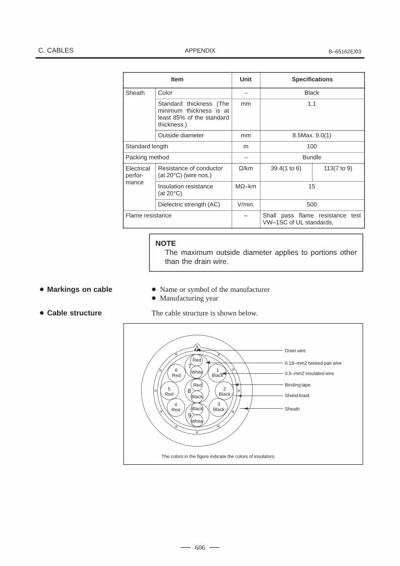
C. CABLES B–65162E/03APPENDIX
606
Item SpecificationsUnit
Sheath Color – Black
Standard thickness (Theminimum thickness is atleast 85% of the standardthickness.)
mm 1.1
Outside diameter mm 8.5Max. 9.0(1)
Standard length m 100
Packing method – Bundle
Electricalperfor-mance
Resistance of conductor(at 20°C) (wire nos.)
Ω/km 39.4(1 to 6) 113(7 to 9)
manceInsulation resistance (at 20°C)
MΩ–km 15
Dielectric strength (AC) V/min. 500
Flame resistance – Shall pass flame resistance testVW–1SC of UL standards,
NOTEThe maximum outside diameter applies to portions otherthan the drain wire.
Name or symbol of the manufacturer Manufacturing year
The cable structure is shown below.
The colors in the figure indicate the colors of insulators.
Drain wire
0.18–mm2 twisted pair wire
0.5–mm2 insulated wire
Binding tape
Shield braid
Sheath
Red
White
Black
1Black
2Black
3Black
4Red
5Red
6Red
7
8
9
Red
Black
White
Markings on cable
Cable structure
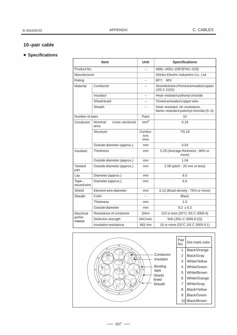
B–65162E/03 C. CABLESAPPENDIX
607
Item Unit Specifications
Product No. – A66L–0001–0367 (FNC–019)
Manufacturer Shinko Electric Industries Co., Ltd.
Rating – 80°C 60V
Material Conductor – Stranded wire of tinned annealed copper(JIS C 3152)
Insulator – Heat–resistant polivinyl chioride
Shield braid – Tinned annealed copper wire
Sheath – Heat–resistant, oil–resistance, flame–retardent polivinyl chioride (S–3)
Number of pairs Pairs 10
Conductor Nominal cross–sectionalarea
mm2 0.18
Structure Conduc-tors/mm
7/0.18
Outside diameter (approx.) mm 0.54
Insulator Thickness mm 0.25 (Average thickness : 90% ormore)
Outside diameter (approx.) mm 1.04
Twistedpair
Outside diameter (approx.) mm 2.08 (pitch : 25 mm or less)
Lay Diameter (approx.) mm 6.5
Tape–wound wire
Diameter (approx.) mm 6.6
Shield Element wire diameter mm 0.12 (Braid density : 75% or more)
Sheath Color – Black
Thickness mm 1.0
Outside diameter mm 9.2 0.3
Electricalperfor
Resistance of conductor Ω/km 110 or less (20°C JIS C 3005 6)perfor-mance
Dielectric strength VAC/min. 500 (JISx C 3005 8 (2))mance
Insulation resistance MΩ–km 15 or more (20°C JIS C 3005 9.1)
1 Black/Orange
Binding tapeShield braidSheath
2 Black/Gray
3 White/Yellow
4 White/Green
5 White/Brown
6 White/Orange
7 White/Gray
8 Black/Yellow
9 Black/Green
10 Black/Brown
PairNo. Dot mark color
InsulatorConductor
4
5
67
2
1
310
9
8
10–pair cable
Specifications
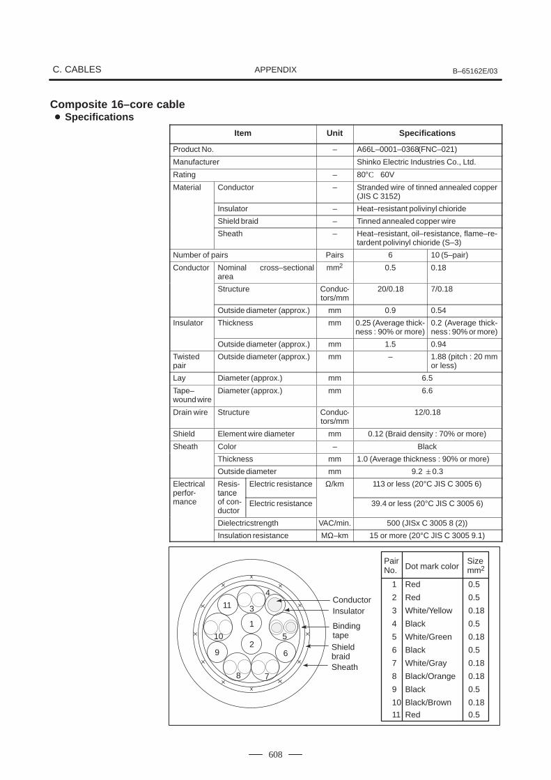
C. CABLES B–65162E/03APPENDIX
608
Composite 16–core cable
Item Unit Specifications
Product No. – A66L–0001–0368 (FNC–021)
Manufacturer Shinko Electric Industries Co., Ltd.
Rating – 80°C 60V
Material Conductor – Stranded wire of tinned annealed copper(JIS C 3152)
Insulator – Heat–resistant polivinyl chioride
Shield braid – Tinned annealed copper wire
Sheath – Heat–resistant, oil–resistance, flame–re-tardent polivinyl chioride (S–3)
Number of pairs Pairs 6 10 (5–pair)
Conductor Nominal cross–sectionalarea
mm2 0.5 0.18
Structure Conduc-tors/mm
20/0.18 7/0.18
Outside diameter (approx.) mm 0.9 0.54
Insulator Thickness mm 0.25 (Average thick-ness : 90% or more)
0.2 (Average thick-ness : 90% or more)
Outside diameter (approx.) mm 1.5 0.94
Twistedpair
Outside diameter (approx.) mm – 1.88 (pitch : 20 mmor less)
Lay Diameter (approx.) mm 6.5
Tape–wound wire
Diameter (approx.) mm 6.6
Drain wire Structure Conduc-tors/mm
12/0.18
Shield Element wire diameter mm 0.12 (Braid density : 70% or more)
Sheath Color – Black
Thickness mm 1.0 (Average thickness : 90% or more)
Outside diameter mm 9.2 0.3
Electricalperfor-
Resis-tance
Electric resistance Ω/km 113 or less (20°C JIS C 3005 6)erfor
mancetanceof con-ductor
Electric resistance 39.4 or less (20°C JIS C 3005 6)
Dielectricstrength VAC/min. 500 (JISx C 3005 8 (2))
Insulation resistance MΩ–km 15 or more (20°C JIS C 3005 9.1)
1 Red 0.5
Binding tapeShield braidSheath
2 Red 0.5
3 White/Yellow 0.18
4 Black 0.5
5 White/Green 0.18
6 Black 0.5
7 White/Gray 0.18
8 Black/Orange 0.18
9 Black 0.5
10 Black/Brown 0.18
PairNo. Dot mark color
InsulatorConductor
1
2
3
4
5
6
78
9
10
11
11 Red 0.5
Sizemm2
Specifications
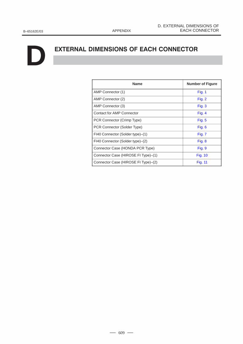
B–65162E/03
D. EXTERNAL DIMENSIONS OFEACH CONNECTORAPPENDIX
609
D
Name Numbe r of Figure
AMP Connector (1) Fig. 1
AMP Connector (2) Fig. 2
AMP Connector (3) Fig. 3
Contact for AMP Connector Fig. 4
PCR Connector (Crimp Type) Fig. 5
PCR Connector (Solder Type) Fig. 6
FI40 Connector (Solder type)–(1) Fig. 7
FI40 Connector (Solder type)–(2) Fig. 8
Connector Case (HONDA PCR Type) Fig. 9
Connector Case (HIROSE FI Type)–(1) Fig. 10
Connector Case (HIROSE FI Type)–(2) Fig. 11
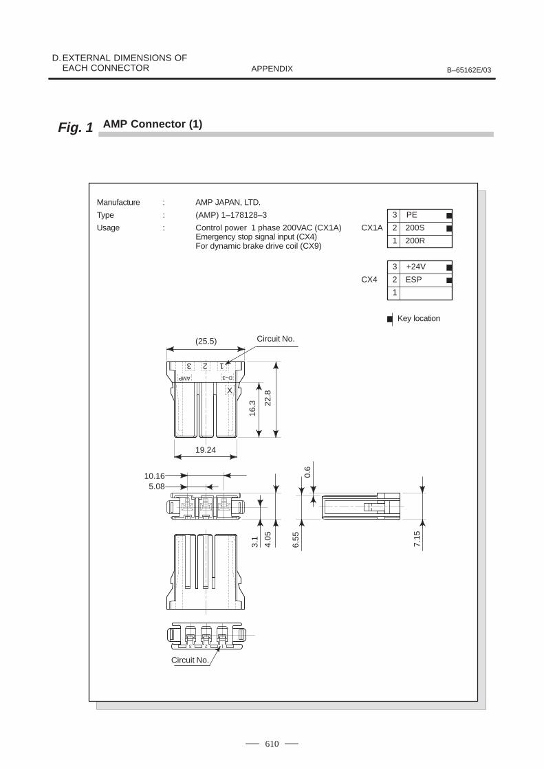
D.EXTERNAL DIMENSIONS OF EACH CONNECTOR B–65162E/03APPENDIX
610
Fig. 1 AMP Connector (1)
3 12
D–3AMP
(25.5)
19.24
16.3 22
.8X
10.165.08
4.05
3.1
123
0.6
6.55
7.15
Circuit No.
Circuit No.
Manufacture : AMP JAPAN, LTD.
Type : (AMP) 1–178128–3
Usage : Control power 1 phase 200VAC (CX1A)Emergency stop signal input (CX4)For dynamic brake drive coil (CX9)
Key location
3
2
1
+24V
ESPCX4
3
2
1
PE
200S
200R
CX1A
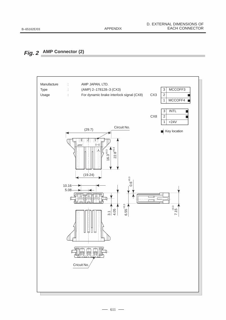
B–65162E/03
D. EXTERNAL DIMENSIONS OFEACH CONNECTORAPPENDIX
611
Fig. 2 AMP Connector (2)
Manufacture : AMP JAPAN, LTD.
Type : (AMP) 2–178128–3 (CX3)
Usage : For dynamic brake interlock signal (CX8)
Key location
3
2
1
MCCOFF3
MCCOFF4
CX3
3 12
AMP
(29.7)
(19.24)
16.3 22
.8
Y
10.165.08
4.05
3.1
123
Cricuit No.
0.6
6.55
7.15
Circuit No.
0.3
0.3
0.3
0.3
0.3
D–3
3
2
1
INTL
+24V
CX8
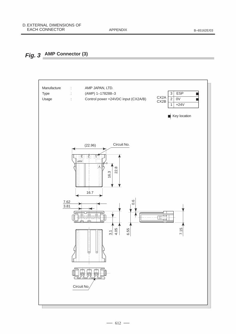
D.EXTERNAL DIMENSIONS OF EACH CONNECTOR B–65162E/03APPENDIX
612
Fig. 3 AMP Connector (3)
Manufacture : AMP JAPAN, LTD.
Type : (AMP) 1–178288–3
Usage : Control power +24VDC input (CX2A/B)
Key location
3
2
1
ESP
0V
+24V
CX2ACX2B
3 12
AMP
(22.96)
16.7
16.3 22
.8
Y
7.623.81
4.05
3.1
123
Circuit No.
0.6
6.55
7.15
Circuit No.
D–3
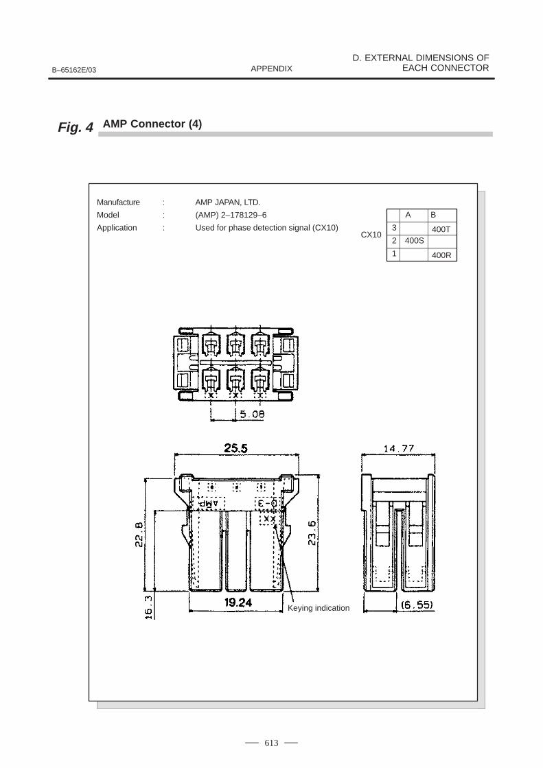
B–65162E/03
D. EXTERNAL DIMENSIONS OFEACH CONNECTORAPPENDIX
613
Fig. 4 AMP Connector (4)
Manufacture : AMP JAPAN, LTD.
Model : (AMP) 2–178129–6
Application : Used for phase detection signal (CX10) 3
2
A
400SCX10
1
400T
400R
B
Keying indication
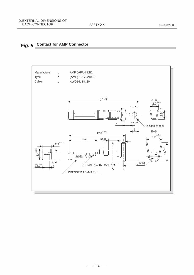
D.EXTERNAL DIMENSIONS OF EACH CONNECTOR B–65162E/03APPENDIX
614
Fig. 5 Contact for AMP Connector
Manufacture : AMP JAPAN, LTD.
Type : (AMP) 1–175218–2
Cable : AWG16, 18, 20
A–A2.9
2.9
B–B
A B
AB
(∅ 2.6)
–AMP
PLATING 1D–MARK
PRESSER 1D–MARK
0.2
0.
2
0.
2
0.5
0.
5
0.4
0.
5
0.4
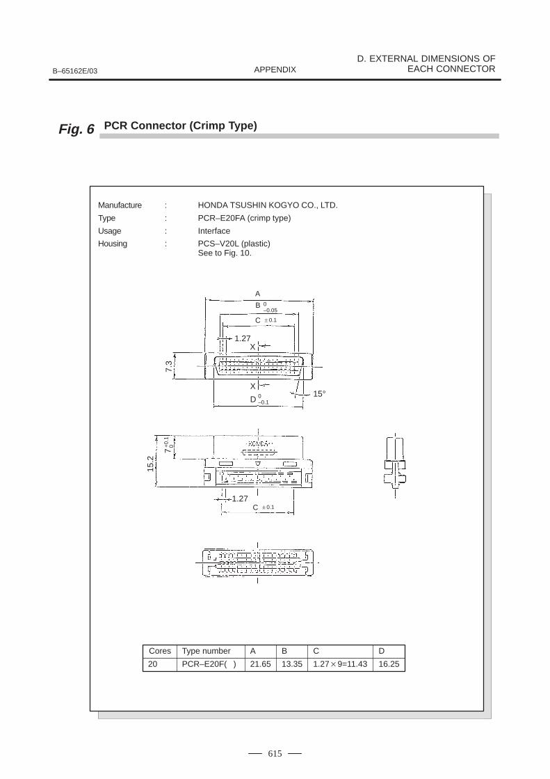
B–65162E/03
D. EXTERNAL DIMENSIONS OFEACH CONNECTORAPPENDIX
615
Fig. 6 PCR Connector (Crimp Type)
Manufacture : HONDA TSUSHIN KOGYO CO., LTD.
Type : PCR–E20FA (crimp type)
Usage : Interface
Housing : PCS–V20L (plastic)See to Fig. 10.
Cores
20
Type number
PCR–E20F( )
A
21.65
B
13.35
C
1.279=11.43
D
16.25
A
B
C
1.27X
X15°
D
1.27
0–0.05
0.1
0–0.1
C 0.1
7.3
15.2
7+
0.1
0
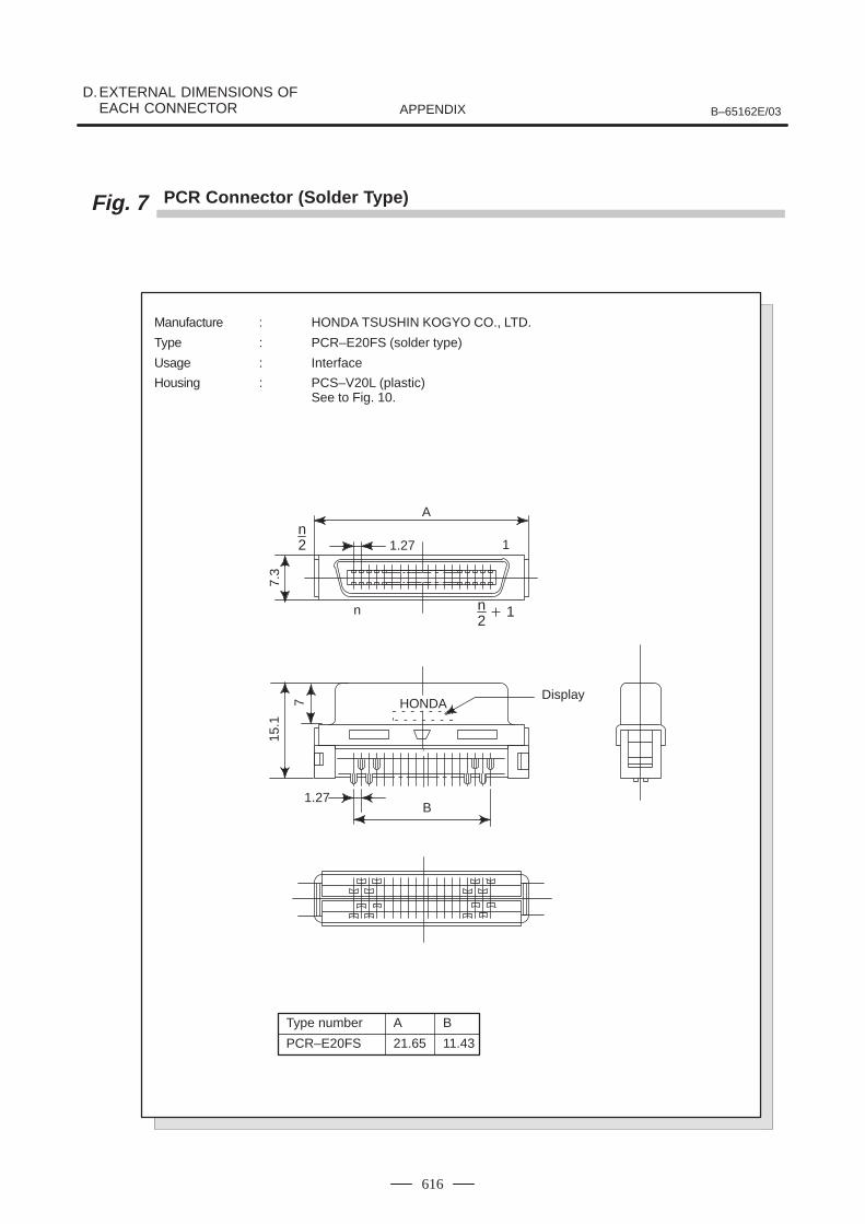
D.EXTERNAL DIMENSIONS OF EACH CONNECTOR B–65162E/03APPENDIX
616
Fig. 7 PCR Connector (Solder Type)
Manufacture : HONDA TSUSHIN KOGYO CO., LTD.
Type : PCR–E20FS (solder type)
Usage : Interface
Housing : PCS–V20L (plastic)See to Fig. 10.
Type number
PCR–E20FS
A
21.65
B
11.43
HONDA
1.27
A
1
7.3
n n2 1
7
15.1
B1.27
Display
n2
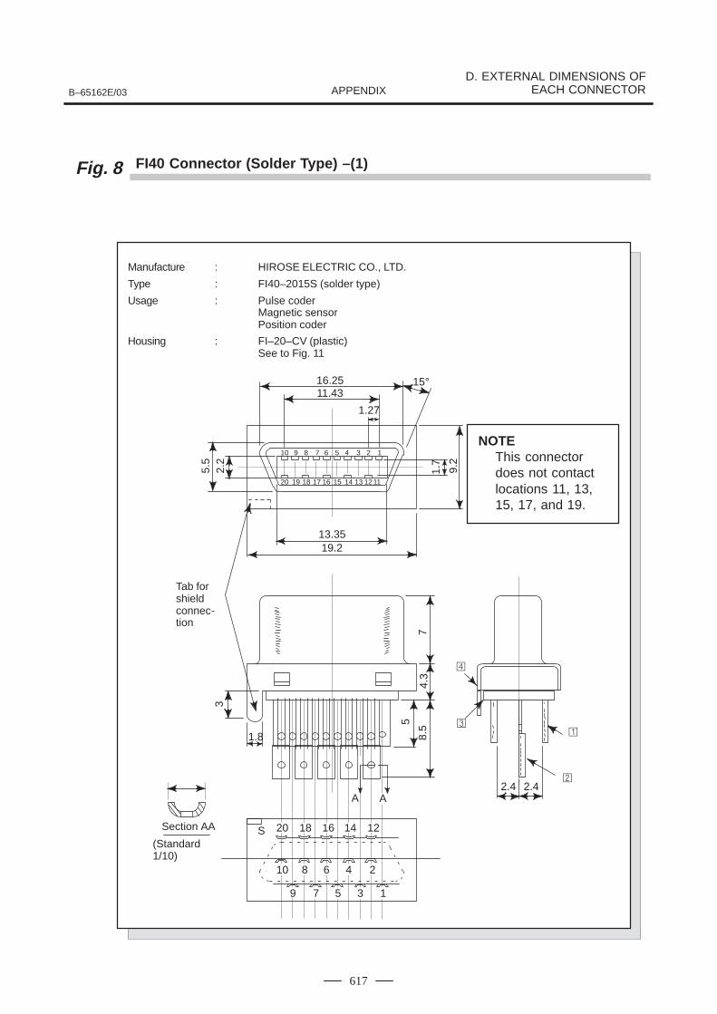
B–65162E/03
D. EXTERNAL DIMENSIONS OFEACH CONNECTORAPPENDIX
617
Fig. 8 FI40 Connector (Solder Type) –(1)
Manufacture : HIROSE ELECTRIC CO., LTD.
Type : FI40–2015S (solder type)
Usage : Pulse coderMagnetic sensorPosition coder
Housing : FI–20–CV (plastic)See to Fig. 11
16.2511.43
1.27
13.3519.2
15°
5.5
2.2
1.7
9.2
12345678910
11121314151617181920
S
1
2
3
4
5
6
7
8
9
10
1214161820Section AA
1.8
3
5
8.5
4.3
7
A A2.4 2.4
Tab forshieldconnec-tion
(Standard1/10)
NOTEThis connectordoes not contactlocations 11, 13,15, 17, and 19.
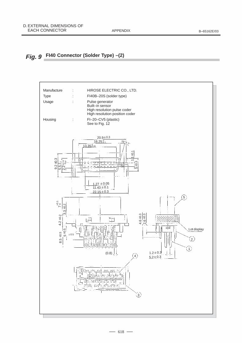
D.EXTERNAL DIMENSIONS OF EACH CONNECTOR B–65162E/03APPENDIX
618
Fig. 9 FI40 Connector (Solder Type) –(2)
Manufacture : HIROSE ELECTRIC CO., LTD.
Type : FI40B–20S (solder type)
Usage : Pulse generatorBuilt–in sensorHigh resolution pulse coderHigh resolution position coder
Housing : FI–20–CV5 (plastic)See to Fig. 12
20.916.25
13.35
1.2711.4322.15
1.25.2
Lot display
(0.8)
0.3
0.30.10.05
0.30.3
1
2
5
3
4
0–0.1
0–0.05
0.
11.
15
0.3
9.2
2.2
5.5 +
0.15
0.
30 –0
.1
0
8.5
5
4.2
7
3.3
0.5
0.
2
4.6
2.6
+0.
10
0.
5
0.
2
0.5
0.
3
0.3
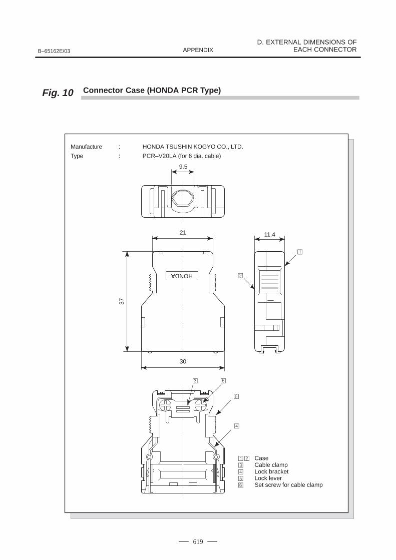
B–65162E/03
D. EXTERNAL DIMENSIONS OFEACH CONNECTORAPPENDIX
619
Fig. 10 Connector Case (HONDA PCR Type)
9.5
HONDA
21
30
37
11.4
Case Cable clamp Lock bracket Lock lever Set screw for cable clamp
Manufacture : HONDA TSUSHIN KOGYO CO., LTD.
Type : PCR–V20LA (for 6 dia. cable)
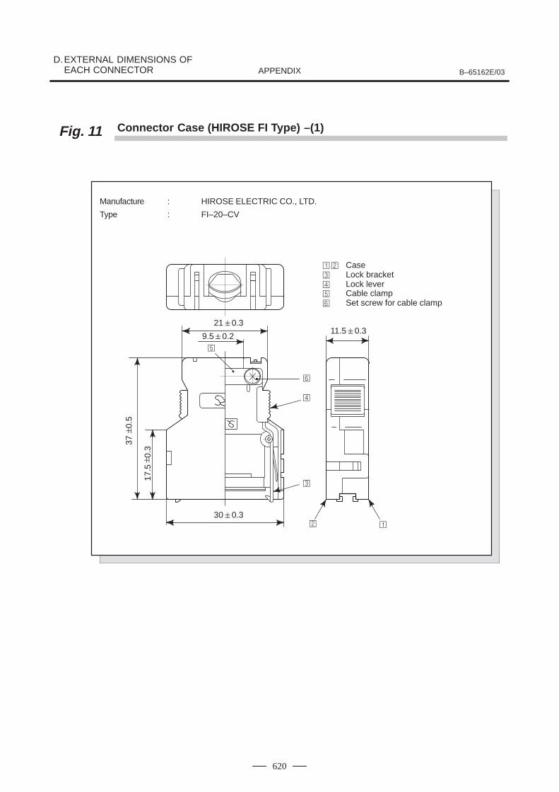
D.EXTERNAL DIMENSIONS OF EACH CONNECTOR B–65162E/03APPENDIX
620
Fig. 11 Connector Case (HIROSE FI Type) –(1)
Manufacture : HIROSE ELECTRIC CO., LTD.
Type : FI–20–CV
210.3
9.50.2
300.3
11.50.3
Case Lock bracket Lock lever Cable clamp Set screw for cable clamp
370.
5
17.5
0.3
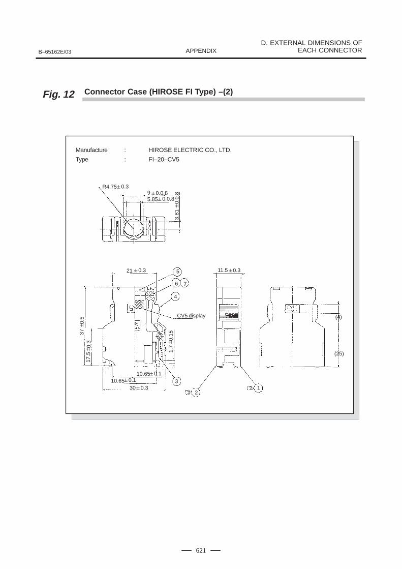
B–65162E/03
D. EXTERNAL DIMENSIONS OFEACH CONNECTORAPPENDIX
621
Fig. 12 Connector Case (HIROSE FI Type) –(2)
Manufacture : HIROSE ELECTRIC CO., LTD.
Type : FI–20–CV5
95.85
21
310.65
10.65
11.5
(25)
(4)
21
2230
0.30.3
0.30.1
0.1
CV5 display
0.0.80.0.8
R4.750.3
5
6 7
4
3.81
3717
.5
1.7
0.
3
0.5
0.
15
0.0.
8

E. CABLE LENGTH B–65162E/03APPENDIX
622
E FEEDBACK CABLE LENGTH
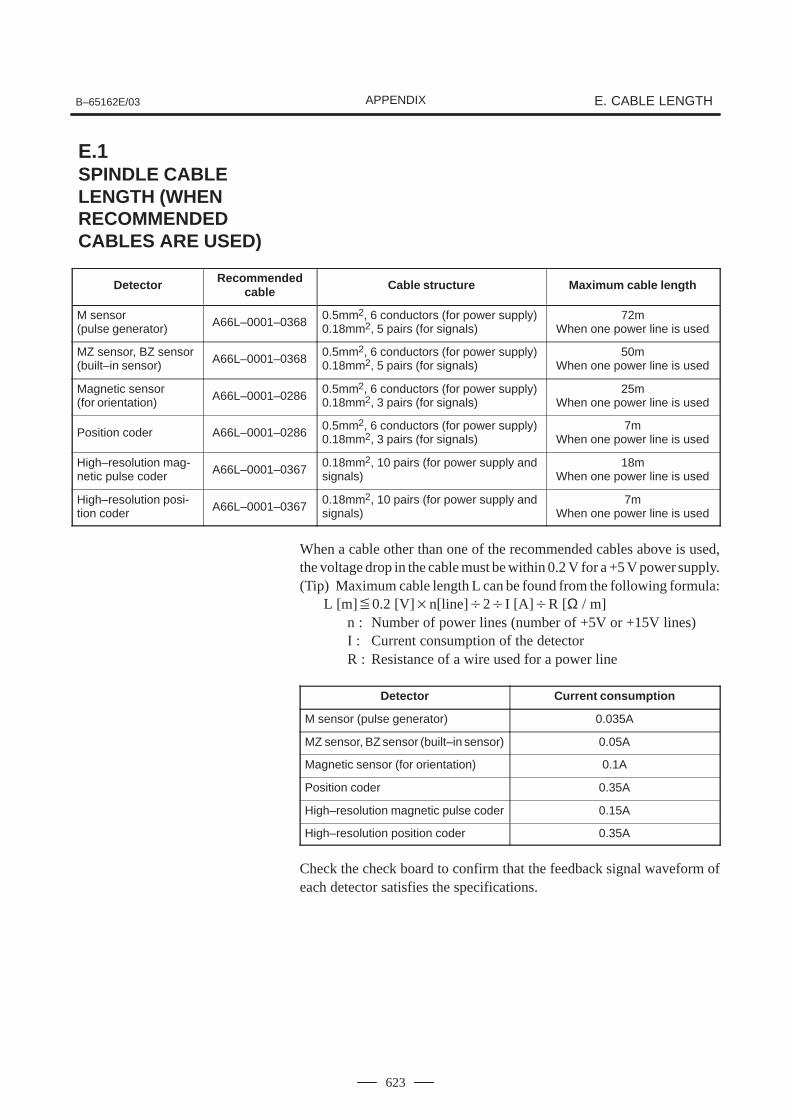
B–65162E/03 E. CABLE LENGTHAPPENDIX
623
Detector Recommendedcable Cable structure Maximum cable length
M sensor (pulse generator) A66L–0001–0368
0.5mm2, 6 conductors (for power supply)0.18mm2, 5 pairs (for signals)
72mWhen one power line is used
MZ sensor, BZ sensor(built–in sensor) A66L–0001–0368
0.5mm2, 6 conductors (for power supply)0.18mm2, 5 pairs (for signals)
50mWhen one power line is used
Magnetic sensor (for orientation) A66L–0001–0286
0.5mm2, 6 conductors (for power supply)0.18mm2, 3 pairs (for signals)
25mWhen one power line is used
Position coder A66L–0001–02860.5mm2, 6 conductors (for power supply)0.18mm2, 3 pairs (for signals)
7mWhen one power line is used
High–resolution mag-netic pulse coder A66L–0001–0367
0.18mm2, 10 pairs (for power supply andsignals)
18mWhen one power line is used
High–resolution posi-tion coder A66L–0001–0367
0.18mm2, 10 pairs (for power supply andsignals)
7mWhen one power line is used
When a cable other than one of the recommended cables above is used,the voltage drop in the cable must be within 0.2 V for a +5 V power supply.(Tip) Maximum cable length L can be found from the following formula:
L [m]0.2 [V]n[line]2I [A]R [Ω / m]n : Number of power lines (number of +5V or +15V lines)I : Current consumption of the detectorR : Resistance of a wire used for a power line
Detector Current consumption
M sensor (pulse generator) 0.035A
MZ sensor, BZ sensor (built–in sensor) 0.05A
Magnetic sensor (for orientation) 0.1A
Position coder 0.35A
High–resolution magnetic pulse coder 0.15A
High–resolution position coder 0.35A
Check the check board to confirm that the feedback signal waveform ofeach detector satisfies the specifications.
E.1SPINDLE CABLE LENGTH (WHEN RECOMMENDEDCABLES ARE USED)
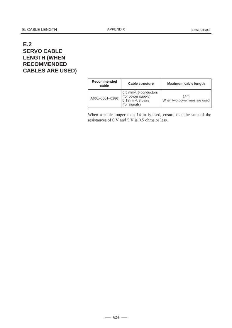
E. CABLE LENGTH B–65162E/03APPENDIX
624
Recommendedcable Cable structure Maximum cable length
A66L–0001–0286
0.5 mm2, 6 conductors (for power supply)0.18mm2, 3 pairs (for signals)
14mWhen two power lines are used
When a cable longer than 14 m is used, ensure that the sum of theresistances of 0 V and 5 V is 0.5 ohms or less.
E.2SERVO CABLE LENGTH (WHEN RECOMMENDEDCABLES ARE USED)
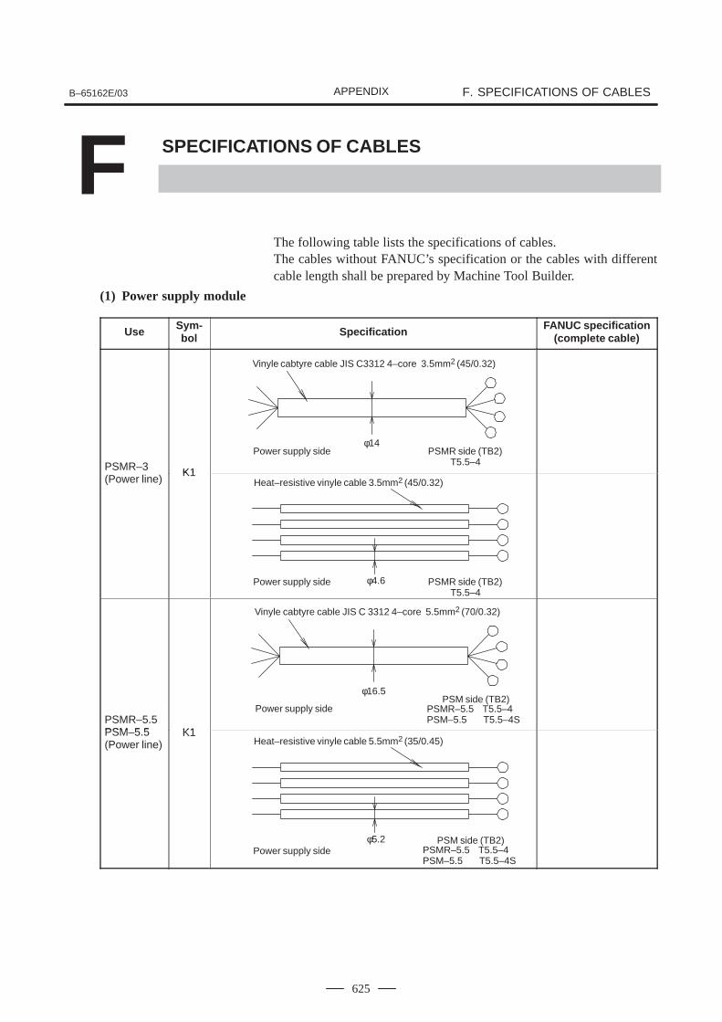
B–65162E/03 F. SPECIFICATIONS OF CABLESAPPENDIX
625
F SPECIFICATIONS OF CABLES
The following table lists the specifications of cables.The cables without FANUC’s specification or the cables with differentcable length shall be prepared by Machine Tool Builder.
(1) Power supply module
Use Sym-bol Specification FANUC specification
(complete cable)
PSMR–3 K1PSMR 3(Power line)
K1
PSMR–5.5PSM 5 5 K1PSM–5.5(Power line)
K1
Vinyle cabtyre cable JIS C3312 4–core 3.5mm2 (45/0.32)
Power supply sideφ14
PSMR side (TB2)T5.5–4
Heat–resistive vinyle cable 3.5mm2 (45/0.32)
Power supply side φ4.6 PSMR side (TB2)T5.5–4
Vinyle cabtyre cable JIS C 3312 4–core 5.5mm2 (70/0.32)
Power supply side
φ16.5PSM side (TB2)
PSMR–5.5 T5.5–4PSM–5.5 T5.5–4S
Heat–resistive vinyle cable 5.5mm2 (35/0.45)
Power supply sideφ5.2 PSM side (TB2)
PSMR–5.5 T5.5–4PSM–5.5 T5.5–4S
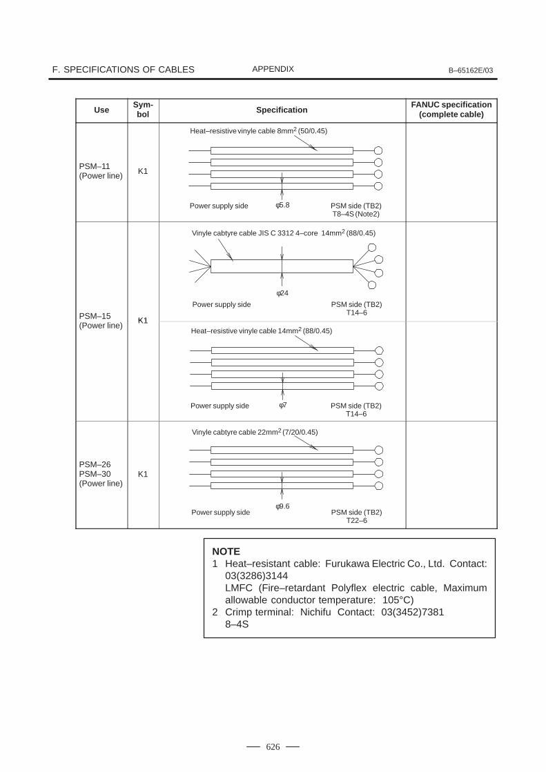
F. SPECIFICATIONS OF CABLES B–65162E/03APPENDIX
626
UseFANUC specification
(complete cable)SpecificationSym-bol
PSM–11(Power line) K1
PSM–15 K1PSM 15(Power line)
K1
PSM–26PSM–30(Power line)
K1
NOTE1 Heat–resistant cable: Furukawa Electric Co., Ltd. Contact:
03(3286)3144LMFC (Fire–retardant Polyflex electric cable, Maximumallowable conductor temperature: 105°C)
2 Crimp terminal: Nichifu Contact: 03(3452)73818–4S
Heat–resistive vinyle cable 8mm2 (50/0.45)
Power supply side φ5.8 PSM side (TB2)T8–4S (Note2)
Vinyle cabtyre cable JIS C 3312 4–core 14mm2 (88/0.45)
Power supply side
φ24
PSM side (TB2)T14–6
Heat–resistive vinyle cable 14mm2 (88/0.45)
Power supply side φ7 PSM side (TB2)T14–6
Vinyle cabtyre cable 22mm2 (7/20/0.45)
Power supply sideφ9.6
PSM side (TB2)T22–6
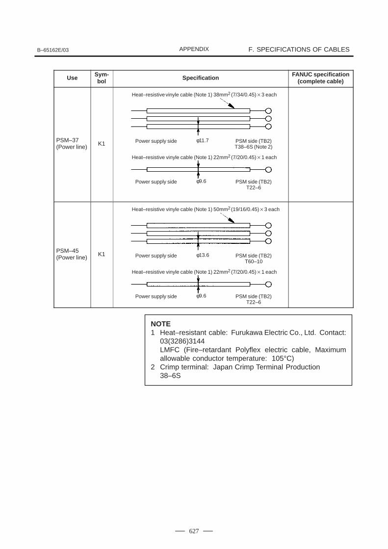
B–65162E/03 F. SPECIFICATIONS OF CABLESAPPENDIX
627
Use Sym-bol Specification FANUC specification
(complete cable)
PSM–37(Power line) K1
PSM–45(Power line) K1
NOTE1 Heat–resistant cable: Furukawa Electric Co., Ltd. Contact:
03(3286)3144LMFC (Fire–retardant Polyflex electric cable, Maximumallowable conductor temperature: 105°C)
2 Crimp terminal: Japan Crimp Terminal Production38–6S
Heat–resistive vinyle cable (Note 1) 38mm2 (7/34/0.45)3 each
Power supply side φ11.7 PSM side (TB2)T38–6S (Note 2)
Heat–resistive vinyle cable (Note 1) 22mm2 (7/20/0.45)1 each
Power supply side φ9.6 PSM side (TB2)T22–6
Heat–resistive vinyle cable (Note 1) 50mm2 (19/16/0.45)3 each
Power supply side φ13.6 PSM side (TB2)T60–10
Heat–resistive vinyle cable (Note 1) 22mm2 (7/20/0.45)1 each
Power supply side φ9.6 PSM side (TB2)T22–6
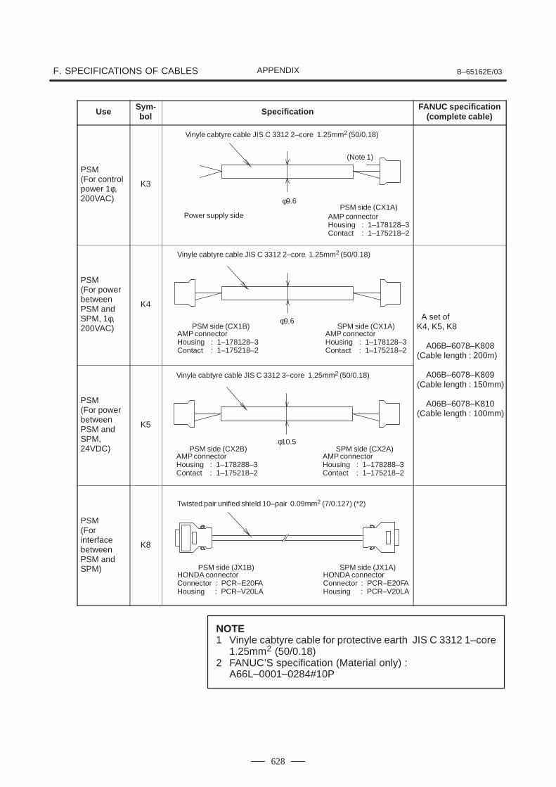
F. SPECIFICATIONS OF CABLES B–65162E/03APPENDIX
628
Use Sym-bol Specification FANUC specification
(complete cable)
PSM(For control power 1φ, 200VAC)
K3
PSM(For power betweenPSM and SPM, 1φ, 200VAC)
K4
A set ofK4, K5, K8
A06B–6078–K808(Cable length : 200m)
PSM(For power betweenPSM and SPM,24VDC)
K5
A06B–6078–K809(Cable length : 150mm)
A06B–6078–K810(Cable length : 100mm)
PSM(For interface betweenPSM and SPM)
K8
NOTE1 Vinyle cabtyre cable for protective earth JIS C 3312 1–core
1.25mm2 (50/0.18)2 FANUC’S specification (Material only) :
A66L–0001–0284#10P
Vinyle cabtyre cable JIS C 3312 2–core 1.25mm2 (50/0.18)
Power supply side
φ9.6PSM side (CX1A)
AMP connectorHousing : 1–178128–3Contact : 1–175218–2
(Note 1)
Vinyle cabtyre cable JIS C 3312 2–core 1.25mm2 (50/0.18)
φ9.6SPM side (CX1A)
AMP connectorHousing : 1–178128–3Contact : 1–175218–2
PSM side (CX1B)AMP connectorHousing : 1–178128–3Contact : 1–175218–2
Vinyle cabtyre cable JIS C 3312 3–core 1.25mm2 (50/0.18)
φ10.5SPM side (CX2A)
AMP connectorHousing : 1–178288–3Contact : 1–175218–2
PSM side (CX2B)AMP connectorHousing : 1–178288–3Contact : 1–175218–2
Twisted pair unified shield 10–pair 0.09mm2 (7/0.127) (*2)
SPM side (JX1A)HONDA connectorConnector : PCR–E20FAHousing : PCR–V20LA
PSM side (JX1B)HONDA connectorConnector : PCR–E20FAHousing : PCR–V20LA
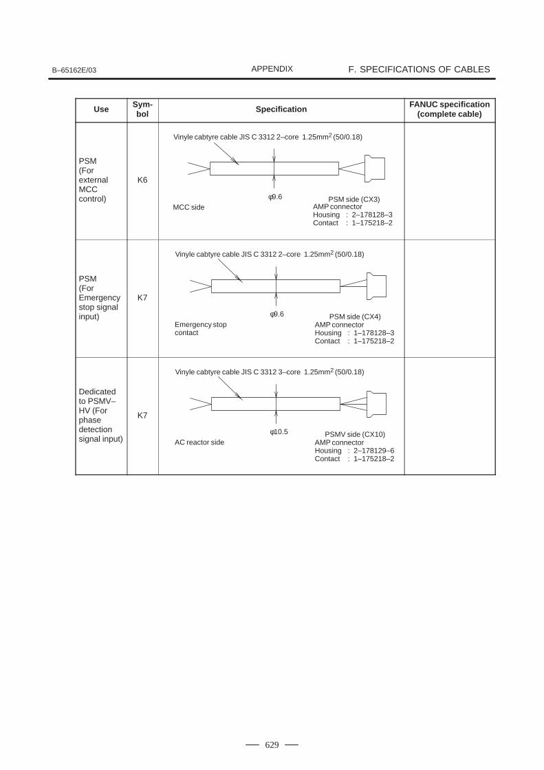
B–65162E/03 F. SPECIFICATIONS OF CABLESAPPENDIX
629
Use Sym-bol Specification FANUC specification
(complete cable)
PSM(For externalMCC control)
K6
PSM(For Emergencystop signal input)
K7
Dedicatedto PSMV–HV (Forphasedetectionsignal input)
K7
Vinyle cabtyre cable JIS C 3312 2–core 1.25mm2 (50/0.18)
MCC sideφ9.6 PSM side (CX3)
AMP connectorHousing : 2–178128–3Contact : 1–175218–2
Vinyle cabtyre cable JIS C 3312 2–core 1.25mm2 (50/0.18)
Emergency stopcontact
φ9.6 PSM side (CX4)AMP connectorHousing : 1–178128–3Contact : 1–175218–2
Vinyle cabtyre cable JIS C 3312 3–core 1.25mm2 (50/0.18)
AC reactor sideφ10.5 PSMV side (CX10)
AMP connectorHousing : 2–178129–6Contact : 1–175218–2
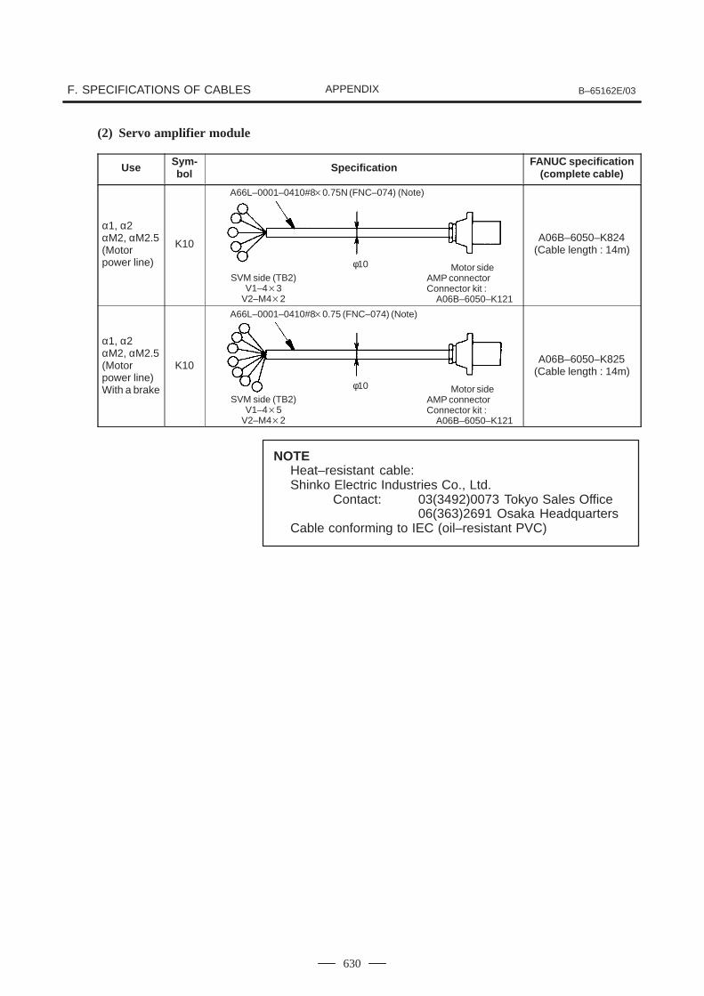
F. SPECIFICATIONS OF CABLES B–65162E/03APPENDIX
630
(2) Servo amplifier module
Use Sym-bol Specification FANUC specification
(complete cable)
α1, α2αM2, αM2.5(Motor power line)
K10A06B–6050–K824
(Cable length : 14m)
α1, α2αM2, αM2.5(Motor power line)With a brake
K10A06B–6050–K825
(Cable length : 14m)
NOTEHeat–resistant cable:Shinko Electric Industries Co., Ltd.
Contact: 03(3492)0073 Tokyo Sales Office06(363)2691 Osaka Headquarters
Cable conforming to IEC (oil–resistant PVC)
A66L–0001–0410#80.75N (FNC–074) (Note)
SVM side (TB2)V1–43
V2–M42
φ10 Motor sideAMP connectorConnector kit :
A06B–6050–K121
A66L–0001–0410#80.75 (FNC–074) (Note)
SVM side (TB2)V1–45
V2–M42
φ10 Motor sideAMP connectorConnector kit :
A06B–6050–K121
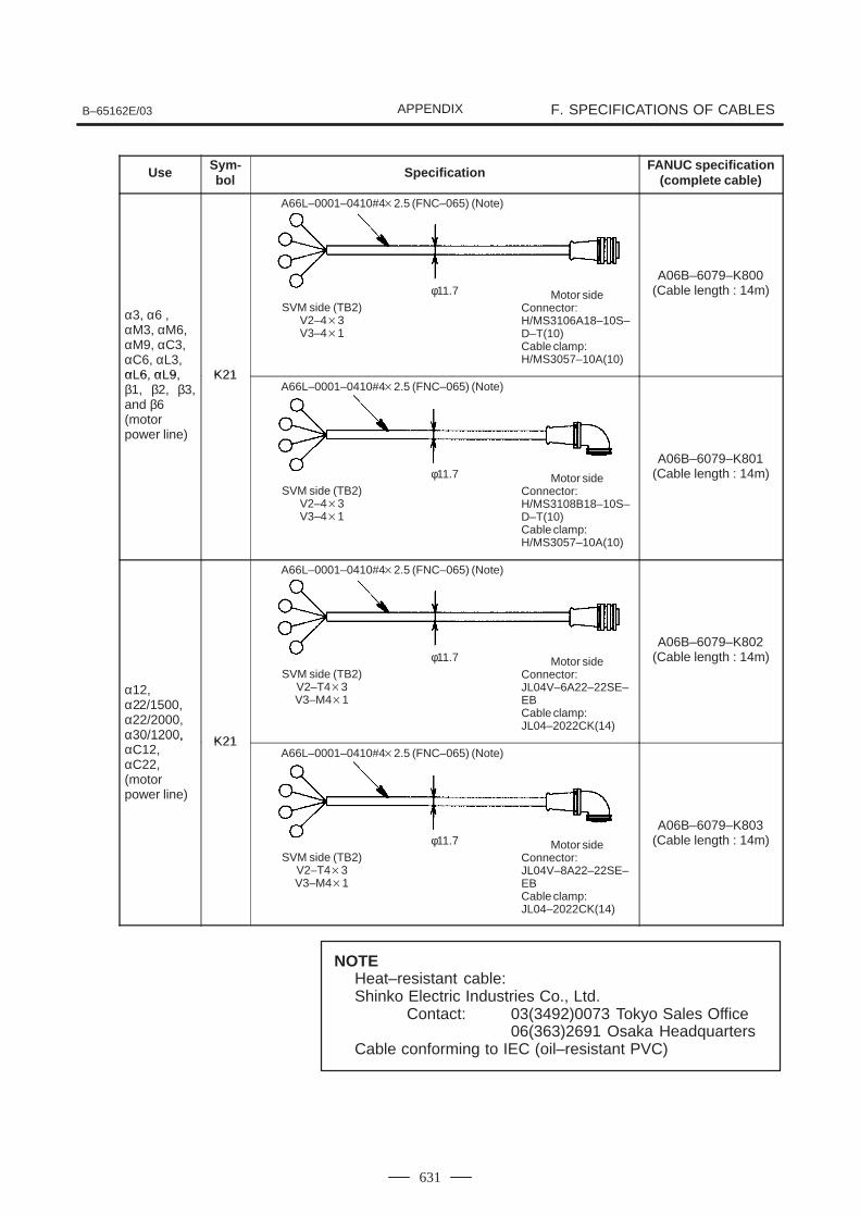
B–65162E/03 F. SPECIFICATIONS OF CABLESAPPENDIX
631
Use Sym-bol Specification FANUC specification
(complete cable)
α3, α6 ,αM3, αM6, αM9, αC3, αC6, αL3, αL6 αL9 K21
A06B–6079–K800(Cable length : 14m)
αL6, αL9, β1, β2, β3,and β6 (motor power line)
K21
A06B–6079–K801(Cable length : 14m)
α12,α22/1500,α22/2000,α30/1200, K21
A06B–6079–K802(Cable length : 14m)
α30/1200,αC12,αC22, (motor power line)
K21
A06B–6079–K803(Cable length : 14m)
NOTEHeat–resistant cable:Shinko Electric Industries Co., Ltd.
Contact: 03(3492)0073 Tokyo Sales Office06(363)2691 Osaka Headquarters
Cable conforming to IEC (oil–resistant PVC)
A66L–0001–0410#42.5 (FNC–065) (Note)
SVM side (TB2)V2–43V3–41
φ11.7 Motor sideConnector:H/MS3106A18–10S–D–T(10)Cable clamp:H/MS3057–10A(10)
A66L–0001–0410#42.5 (FNC–065) (Note)
SVM side (TB2)V2–43V3–41
φ11.7 Motor sideConnector:H/MS3108B18–10S–D–T(10)Cable clamp:H/MS3057–10A(10)
A66L–0001–0410#42.5 (FNC–065) (Note)
SVM side (TB2)V2–T43V3–M41
φ11.7 Motor sideConnector:JL04V–6A22–22SE–EBCable clamp:JL04–2022CK(14)
A66L–0001–0410#42.5 (FNC–065) (Note)
SVM side (TB2)V2–T43V3–M41
φ11.7 Motor sideConnector:JL04V–8A22–22SE–EBCable clamp:JL04–2022CK(14)
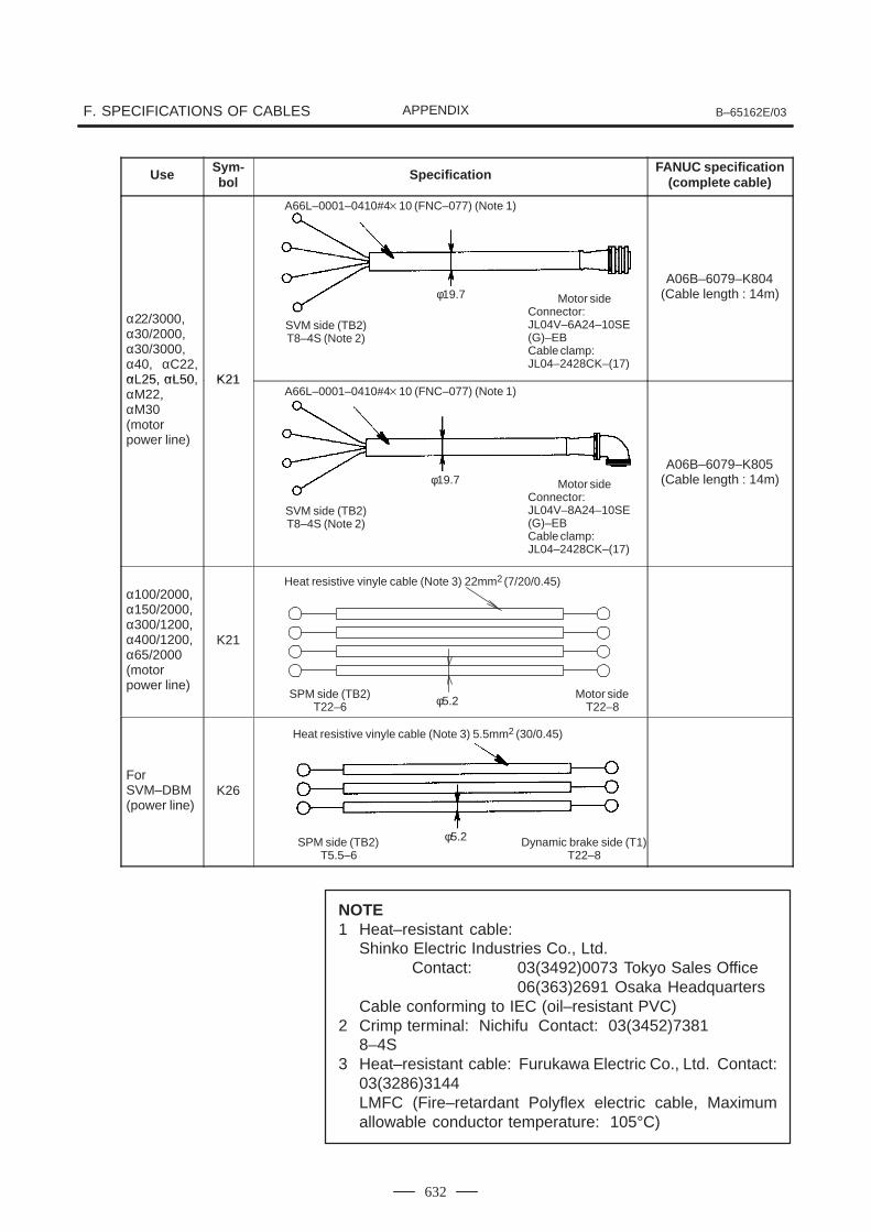
F. SPECIFICATIONS OF CABLES B–65162E/03APPENDIX
632
Use Sym-bol Specification FANUC specification
(complete cable)
α22/3000,α30/2000,α30/3000,α40, αC22,αL25 αL50 K21
A06B–6079–K804(Cable length : 14m)
αL25, αL50,αM22,αM30 (motor power line)
K21
A06B–6079–K805(Cable length : 14m)
α100/2000,α150/2000,α300/1200,α400/1200,α65/2000(motor power line)
K21
For SVM–DBM (power line)
K26
NOTE1 Heat–resistant cable:
Shinko Electric Industries Co., Ltd. Contact: 03(3492)0073 Tokyo Sales Office
06(363)2691 Osaka HeadquartersCable conforming to IEC (oil–resistant PVC)
2 Crimp terminal: Nichifu Contact: 03(3452)73818–4S
3 Heat–resistant cable: Furukawa Electric Co., Ltd. Contact:03(3286)3144LMFC (Fire–retardant Polyflex electric cable, Maximumallowable conductor temperature: 105°C)
A66L–0001–0410#410 (FNC–077) (Note 1)
SVM side (TB2)T8–4S (Note 2)
φ19.7 Motor sideConnector:JL04V–6A24–10SE(G)–EBCable clamp:JL04–2428CK–(17)
A66L–0001–0410#410 (FNC–077) (Note 1)
SVM side (TB2)T8–4S (Note 2)
φ19.7 Motor sideConnector:JL04V–8A24–10SE(G)–EBCable clamp:JL04–2428CK–(17)
Heat resistive vinyle cable (Note 3) 22mm2 (7/20/0.45)
SPM side (TB2)T22–6 φ5.2
Motor sideT22–8
Heat resistive vinyle cable (Note 3) 5.5mm2 (30/0.45)
SPM side (TB2)T5.5–6
φ5.2 Dynamic brake side (T1)T22–8
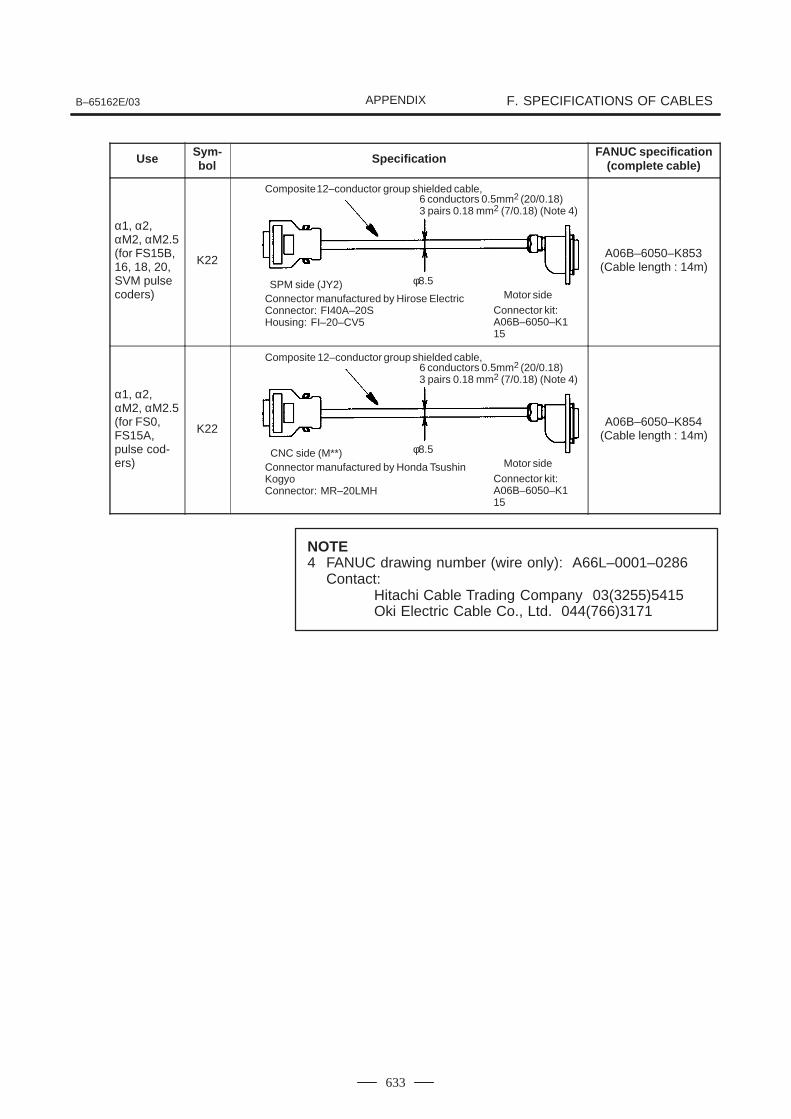
B–65162E/03 F. SPECIFICATIONS OF CABLESAPPENDIX
633
Use Sym-bol Specification FANUC specification
(complete cable)
α1, α2,αM2, αM2.5(for FS15B,16, 18, 20,SVM pulsecoders)
K22A06B–6050–K853
(Cable length : 14m)
α1, α2,αM2, αM2.5(for FS0,FS15A,pulse cod-ers)
K22A06B–6050–K854
(Cable length : 14m)
NOTE4 FANUC drawing number (wire only): A66L–0001–0286
Contact:Hitachi Cable Trading Company 03(3255)5415Oki Electric Cable Co., Ltd. 044(766)3171
Composite 12–conductor group shielded cable,
SPM side (JY2) φ8.5Motor side
6 conductors 0.5mm2 (20/0.18)3 pairs 0.18 mm2 (7/0.18) (Note 4)
Connector manufactured by Hirose ElectricConnector: FI40A–20SHousing: FI–20–CV5
Connector kit:A06B–6050–K115
Composite 12–conductor group shielded cable,
CNC side (M**) φ8.5Motor side
6 conductors 0.5mm2 (20/0.18)3 pairs 0.18 mm2 (7/0.18) (Note 4)
Connector manufactured by Honda TsushinKogyoConnector: MR–20LMH
Connector kit:A06B–6050–K115
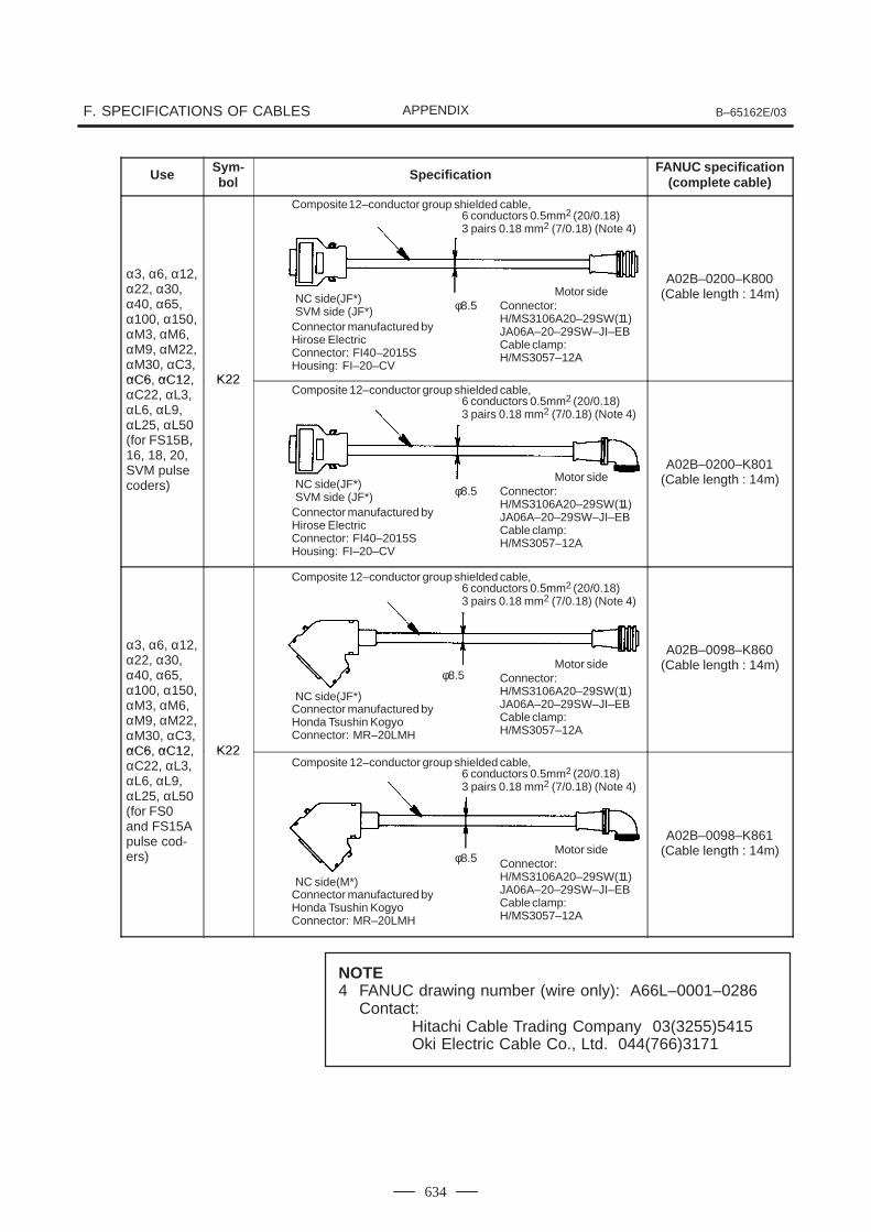
F. SPECIFICATIONS OF CABLES B–65162E/03APPENDIX
634
Use Sym-bol Specification FANUC specification
(complete cable)
α3, α6, α12,α22, α30,α40, α65,α100, α150,αM3, αM6,αM9, αM22,αM30, αC3,αC6 αC12 K22
A02B–0200–K800(Cable length : 14m)
αC6, αC12,αC22, αL3,αL6, αL9,αL25, αL50(for FS15B,16, 18, 20,SVM pulsecoders)
K22
A02B–0200–K801(Cable length : 14m)
α3, α6, α12,α22, α30,α40, α65,α100, α150,αM3, αM6,αM9, αM22,αM30, αC3,αC6 αC12 K22
A02B–0098–K860(Cable length : 14m)
αC6, αC12,αC22, αL3,αL6, αL9,αL25, αL50(for FS0and FS15Apulse cod-ers)
K22
A02B–0098–K861(Cable length : 14m)
NOTE4 FANUC drawing number (wire only): A66L–0001–0286
Contact:Hitachi Cable Trading Company 03(3255)5415Oki Electric Cable Co., Ltd. 044(766)3171
Composite 12–conductor group shielded cable,
NC side(JF*)SVM side (JF*) φ8.5
Motor side
6 conductors 0.5mm2 (20/0.18)3 pairs 0.18 mm2 (7/0.18) (Note 4)
Connector manufactured byHirose ElectricConnector: FI40–2015SHousing: FI–20–CV
Connector:H/MS3106A20–29SW(11)JA06A–20–29SW–JI–EBCable clamp:H/MS3057–12A
Composite 12–conductor group shielded cable,
NC side(JF*)
φ8.5Motor side
6 conductors 0.5mm2 (20/0.18)3 pairs 0.18 mm2 (7/0.18) (Note 4)
Connector manufactured byHonda Tsushin KogyoConnector: MR–20LMH
Connector:H/MS3106A20–29SW(11)JA06A–20–29SW–JI–EBCable clamp:H/MS3057–12A
Composite 12–conductor group shielded cable,
NC side(M*)
φ8.5Motor side
6 conductors 0.5mm2 (20/0.18)3 pairs 0.18 mm2 (7/0.18) (Note 4)
Connector manufactured byHonda Tsushin KogyoConnector: MR–20LMH
Connector:H/MS3106A20–29SW(11)JA06A–20–29SW–JI–EBCable clamp:H/MS3057–12A
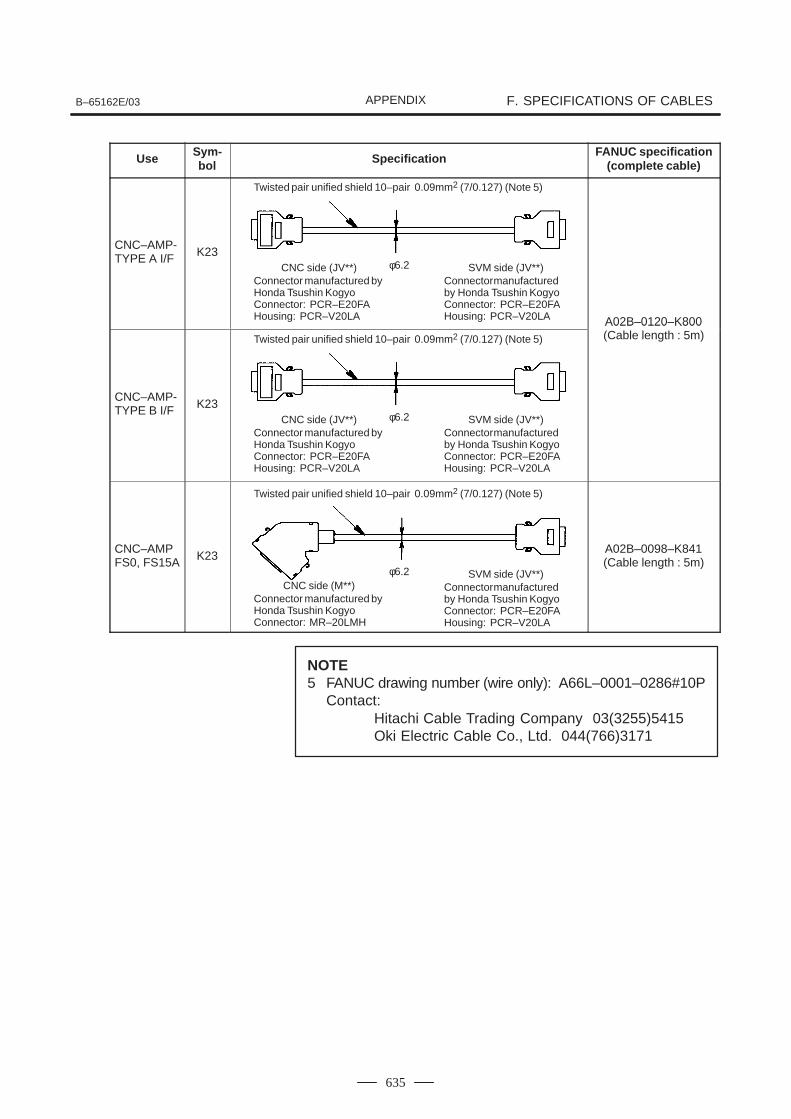
B–65162E/03 F. SPECIFICATIONS OF CABLESAPPENDIX
635
Use Sym-bol Specification FANUC specification
(complete cable)
CNC–AMP-TYPE A I/F K23
A02B–0120–K800
CNC–AMP-TYPE B I/F K23
A02B 0120 K800(Cable length : 5m)
CNC–AMPFS0, FS15A K23
A02B–0098–K841(Cable length : 5m)
NOTE5 FANUC drawing number (wire only): A66L–0001–0286#10P
Contact: Hitachi Cable Trading Company 03(3255)5415Oki Electric Cable Co., Ltd. 044(766)3171
Twisted pair unified shield 10–pair 0.09mm2 (7/0.127) (Note 5)
CNC side (JV**)Connector manufactured byHonda Tsushin KogyoConnector: PCR–E20FAHousing: PCR–V20LA
SVM side (JV**)Connector manufacturedby Honda Tsushin KogyoConnector: PCR–E20FAHousing: PCR–V20LA
φ6.2
Twisted pair unified shield 10–pair 0.09mm2 (7/0.127) (Note 5)
CNC side (JV**)Connector manufactured byHonda Tsushin KogyoConnector: PCR–E20FAHousing: PCR–V20LA
SVM side (JV**)Connector manufacturedby Honda Tsushin KogyoConnector: PCR–E20FAHousing: PCR–V20LA
φ6.2
Twisted pair unified shield 10–pair 0.09mm2 (7/0.127) (Note 5)
CNC side (M**)Connector manufactured byHonda Tsushin KogyoConnector: MR–20LMH
SVM side (JV**)Connector manufacturedby Honda Tsushin KogyoConnector: PCR–E20FAHousing: PCR–V20LA
φ6.2
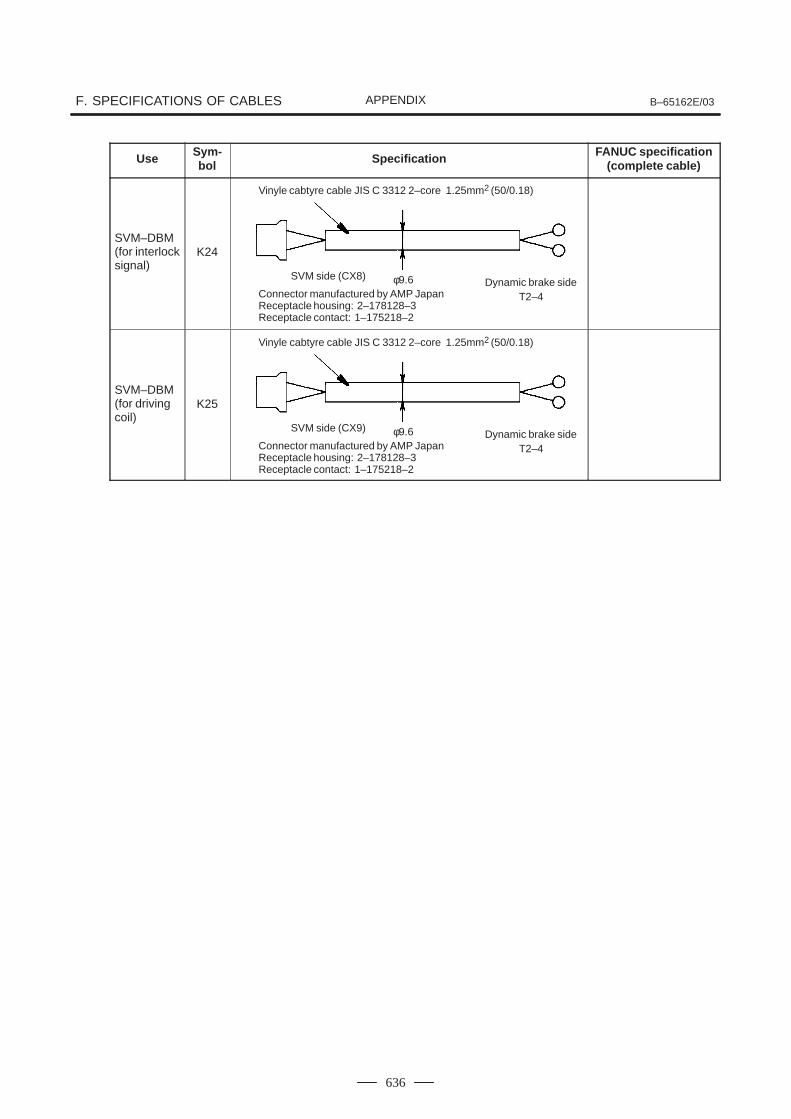
F. SPECIFICATIONS OF CABLES B–65162E/03APPENDIX
636
Use Sym-bol Specification FANUC specification
(complete cable)
SVM–DBM(for interlocksignal)
K24
SVM–DBM(for drivingcoil)
K25
Vinyle cabtyre cable JIS C 3312 2–core 1.25mm2 (50/0.18)
SVM side (CX8) φ9.6 Dynamic brake sideT2–4Connector manufactured by AMP Japan
Receptacle housing: 2–178128–3Receptacle contact: 1–175218–2
Vinyle cabtyre cable JIS C 3312 2–core 1.25mm2 (50/0.18)
SVM side (CX9) φ9.6 Dynamic brake sideT2–4Connector manufactured by AMP Japan
Receptacle housing: 2–178128–3Receptacle contact: 1–175218–2
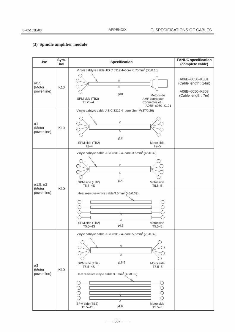
B–65162E/03 F. SPECIFICATIONS OF CABLESAPPENDIX
637
(3) Spindle amplifier module
Use Sym-bol Specification FANUC specification
(complete cable)
α0.5(Motor power line)
K10
A06B–6050–K801(Cable length : 14m)
A06B–6050–K803(Cable length : 7m)
α1(Motor power line)
K10
α1.5, α2(Motor K10(Motor power line)
K10
α3(Motor K10(Motor power line)
K10
Vinyle cabtyre cable JIS C 3312 4–core 0.75mm2 (30/0.18)
SPM side (TB2)T1.25–4
φ10 Motor sideAMP connectorConnector kit :
A06B–6050–K121
Vinyle cabtyre cable JIS C 3312 4–core 2mm2 (37/0.26)
SPM side (TB2)T2–4
φ12Motor side
T2–5
Vinyle cabtyre cable JIS C 3312 4–core 3.5mm2 (45/0.32)
SPM side (TB2)T5.5–4S
φ14 Motor sideT5.5–5
Heat resistive vinyle cable 3.5mm2 (45/0.32)
SPM side (TB2)T5.5–4S φ4.6
Motor sideT5.5–5
Vinyle cabtyre cable JIS C 3312 4–core 5.5mm2 (70/0.32)
SPM side (TB2)T5.5–4S
φ16.5 Motor sideT5.5–5
Heat resistive vinyle cable 3.5mm2 (45/0.32)
SPM side (TB2)T5.5–4S φ4.6
Motor sideT5.5–5
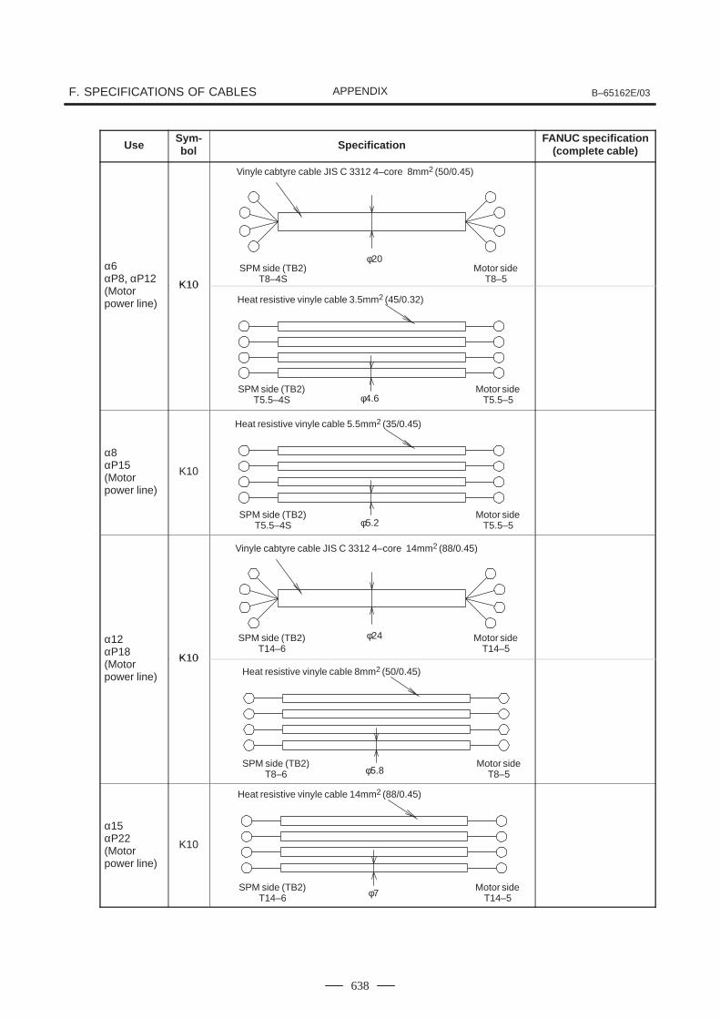
F. SPECIFICATIONS OF CABLES B–65162E/03APPENDIX
638
UseFANUC specification
(complete cable)SpecificationSym-bol
α6αP8, αP12 K10α , α(Motor power line)
K10
α8αP15(Motor power line)
K10
α12αP18 K10α(Motor power line)
K10
α15αP22(Motor power line)
K10
Vinyle cabtyre cable JIS C 3312 4–core 8mm2 (50/0.45)
SPM side (TB2)T8–4S
φ20Motor side
T8–5
Heat resistive vinyle cable 3.5mm2 (45/0.32)
SPM side (TB2)T5.5–4S φ4.6
Motor sideT5.5–5
Heat resistive vinyle cable 5.5mm2 (35/0.45)
SPM side (TB2)T5.5–4S φ5.2
Motor sideT5.5–5
Vinyle cabtyre cable JIS C 3312 4–core 14mm2 (88/0.45)
SPM side (TB2)T14–6
φ24 Motor sideT14–5
Heat resistive vinyle cable 8mm2 (50/0.45)
SPM side (TB2)T8–6 φ5.8
Motor sideT8–5
Heat resistive vinyle cable 14mm2 (88/0.45)
SPM side (TB2)T14–6 φ7
Motor sideT14–5
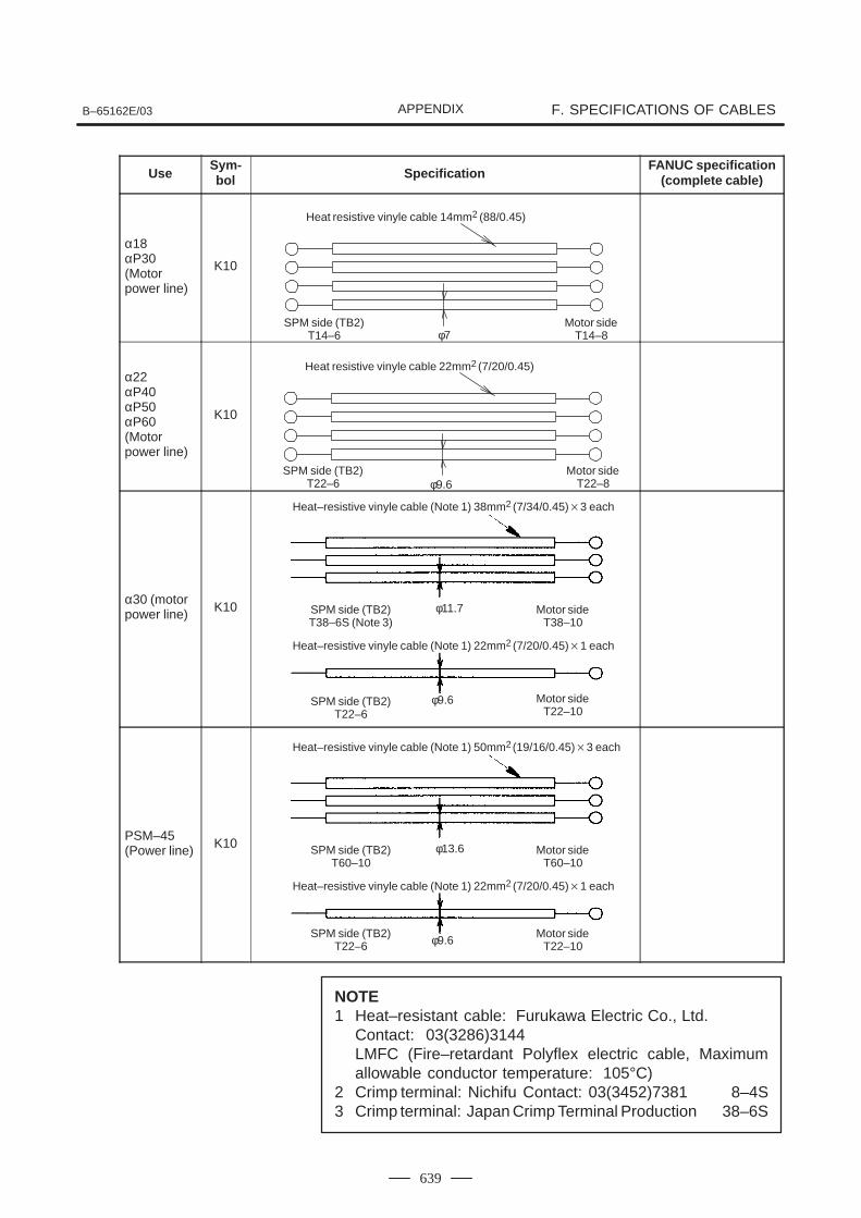
B–65162E/03 F. SPECIFICATIONS OF CABLESAPPENDIX
639
UseFANUC specification
(complete cable)SpecificationSym-bol
α18αP30(Motor power line)
K10
α22αP40αP50αP60(Motor power line)
K10
α30 (motorpower line) K10
PSM–45(Power line) K10
NOTE1 Heat–resistant cable: Furukawa Electric Co., Ltd.
Contact: 03(3286)3144LMFC (Fire–retardant Polyflex electric cable, Maximumallowable conductor temperature: 105°C)
2 Crimp terminal: Nichifu Contact: 03(3452)7381 8–4S3 Crimp terminal: Japan Crimp Terminal Production 38–6S
Heat resistive vinyle cable 14mm2 (88/0.45)
SPM side (TB2)T14–6 φ7
Motor sideT14–8
Heat resistive vinyle cable 22mm2 (7/20/0.45)
SPM side (TB2)T22–6 φ9.6
Motor sideT22–8
Heat–resistive vinyle cable (Note 1) 38mm2 (7/34/0.45)3 each
SPM side (TB2)T38–6S (Note 3)
φ11.7 Motor sideT38–10
Heat–resistive vinyle cable (Note 1) 22mm2 (7/20/0.45)1 each
SPM side (TB2)T22–6
φ9.6 Motor sideT22–10
Heat–resistive vinyle cable (Note 1) 50mm2 (19/16/0.45)3 each
SPM side (TB2)T60–10
φ13.6 Motor sideT60–10
Heat–resistive vinyle cable (Note 1) 22mm2 (7/20/0.45)1 each
SPM side (TB2)T22–6 φ9.6
Motor sideT22–10
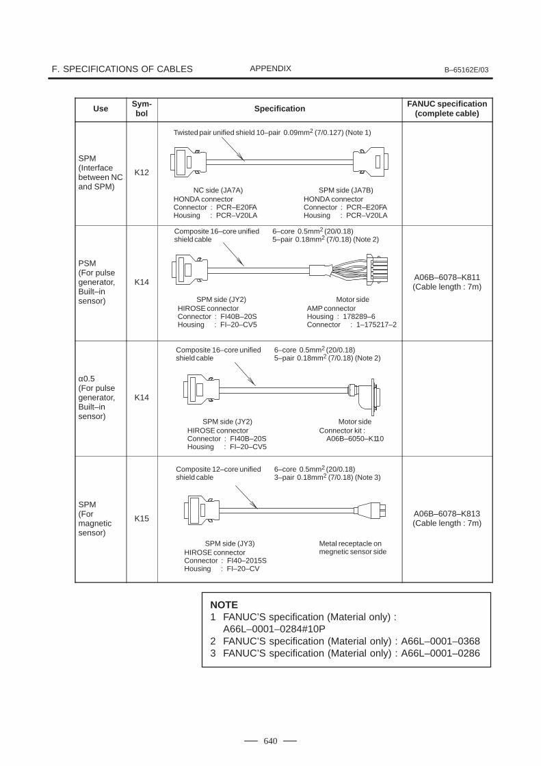
F. SPECIFICATIONS OF CABLES B–65162E/03APPENDIX
640
Use Sym-bol Specification FANUC specification
(complete cable)
SPM(Interfacebetween NCand SPM)
K12
PSM(For pulse generator,Built–in sensor)
K14A06B–6078–K811(Cable length : 7m)
α0.5(For pulse generator,Built–in sensor)
K14
SPM(For magneticsensor)
K15A06B–6078–K813(Cable length : 7m)
NOTE1 FANUC’S specification (Material only) :
A66L–0001–0284#10P2 FANUC’S specification (Material only) : A66L–0001–03683 FANUC’S specification (Material only) : A66L–0001–0286
Twisted pair unified shield 10–pair 0.09mm2 (7/0.127) (Note 1)
NC side (JA7A)HONDA connectorConnector : PCR–E20FAHousing : PCR–V20LA
SPM side (JA7B)HONDA connectorConnector : PCR–E20FAHousing : PCR–V20LA
Composite 16–core unified 6–core 0.5mm2 (20/0.18)shield cable 5–pair 0.18mm2 (7/0.18) (Note 2)
SPM side (JY2)HIROSE connectorConnector : FI40B–20SHousing : FI–20–CV5
Motor sideAMP connectorHousing : 178289–6Connector : 1–175217–2
Composite 16–core unified 6–core 0.5mm2 (20/0.18)shield cable 5–pair 0.18mm2 (7/0.18) (Note 2)
SPM side (JY2)HIROSE connectorConnector : FI40B–20SHousing : FI–20–CV5
Motor sideConnector kit :
A06B–6050–K110
Composite 12–core unified 6–core 0.5mm2 (20/0.18)shield cable 3–pair 0.18mm2 (7/0.18) (Note 3)
SPM side (JY3)HIROSE connectorConnector : FI40–2015SHousing : FI–20–CV
Metal receptacle on megnetic sensor side
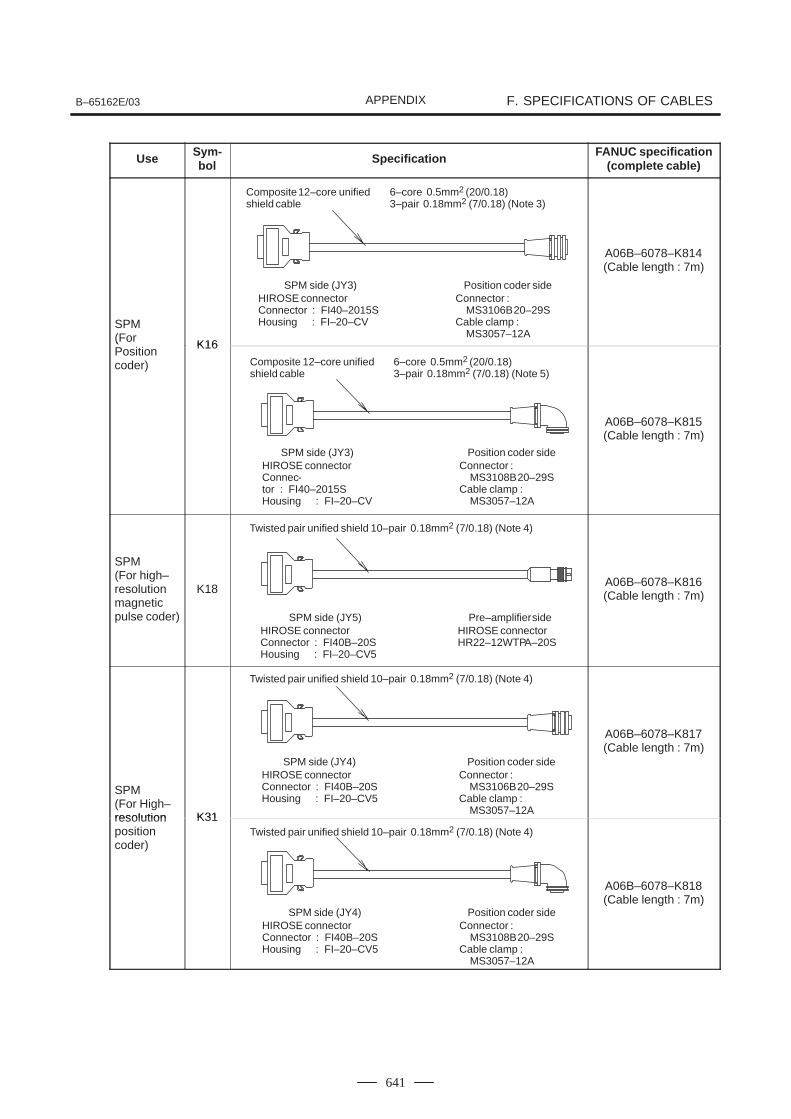
B–65162E/03 F. SPECIFICATIONS OF CABLESAPPENDIX
641
Use Sym-bol Specification FANUC specification
(complete cable)
SPM(For K16
A06B–6078–K814(Cable length : 7m)
(Positioncoder)
K16
A06B–6078–K815(Cable length : 7m)
SPM(For high–resolutionmagneticpulse coder)
K18A06B–6078–K816(Cable length : 7m)
SPM(For High–resolution K31
A06B–6078–K817(Cable length : 7m)
resolutionpositioncoder)
K31
A06B–6078–K818(Cable length : 7m)
Composite 12–core unified 6–core 0.5mm2 (20/0.18)shield cable 3–pair 0.18mm2 (7/0.18) (Note 3)
SPM side (JY3)HIROSE connectorConnector : FI40–2015SHousing : FI–20–CV
Position coder sideConnector :
MS3106B 20–29SCable clamp :
MS3057–12A
Composite 12–core unified 6–core 0.5mm2 (20/0.18)shield cable 3–pair 0.18mm2 (7/0.18) (Note 5)
SPM side (JY3)HIROSE connectorConnec-tor : FI40–2015SHousing : FI–20–CV
Position coder sideConnector :
MS3108B 20–29SCable clamp :
MS3057–12A
Twisted pair unified shield 10–pair 0.18mm2 (7/0.18) (Note 4)
SPM side (JY5)HIROSE connectorConnector : FI40B–20SHousing : FI–20–CV5
Pre–amplifier sideHIROSE connectorHR22–12WTPA–20S
Twisted pair unified shield 10–pair 0.18mm2 (7/0.18) (Note 4)
SPM side (JY4)HIROSE connectorConnector : FI40B–20SHousing : FI–20–CV5
Position coder sideConnector :
MS3106B 20–29SCable clamp :
MS3057–12A
Twisted pair unified shield 10–pair 0.18mm2 (7/0.18) (Note 4)
SPM side (JY4)HIROSE connectorConnector : FI40B–20SHousing : FI–20–CV5
Position coder sideConnector :
MS3108B 20–29SCable clamp :
MS3057–12A

F. SPECIFICATIONS OF CABLES B–65162E/03APPENDIX
642
NOTE1 FANUC’S specification (Material only) :
A66L–0001–0284#10P2 FANUC’S specification (Material only) : A66L–0001–03683 FANUC’S specification (Material only) : A66L–0001–02864 FANUC’S specification (Material only) : A66L–0001–0367

B–65162E/03
G. SERVO AMPLIFIER NOISEPROTECTIONAPPENDIX
643
G SERVO AMPLIFIER NOISE PROTECTION
This appendix describes how noise is generated when a servo motor orspindle motor is driven by a servo amplifier, and also describescountermeasures required for devices affected by noise.While referring to this appendix, the user should pay careful attention tonoise protection when installing the machine.
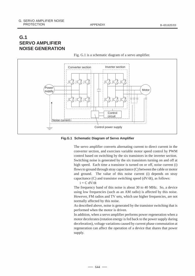
G. SERVO AMPLIFIER NOISE PROTECTION B–65162E/03APPENDIX
644
Fig. G.1 is a schematic diagram of a servo amplifier.
Converter section Inverter section
Powersupply Motor
Noise current i
Control power supply
Control circuit
Fig.G.1 Schematic Diagram of Servo Amplifier
The servo amplifier converts alternating current to direct current in theconverter section, and exercises variable motor speed control by PWMcontrol based on switching by the six transistors in the inverter section.Switching noise is generated by the six transistors turning on and off athigh speed. Each time a transistor is turned on or off, noise current (i)flows to ground through stray capacitance (C) between the cable or motorand ground. The value of this noise current (i) depends on straycapacitance (C) and transistor switching speed (dV/dt), as follows:
i = C dV/dtThe frequency band of this noise is about 30 to 40 MHz. So, a deviceusing low frequencies (such as an AM radio) is affected by this noise.However, FM radios and TV sets, which use higher frequencies, are notnormally affected by this noise.As described above, noise is generated by the transistor switching that isperformed when the motor is driven.In addition, when a servo amplifier performs power regeneration when amotor decelerates (rotation energy is fed back to the power supply duringdeceleration), voltage variations caused by current phase commutation atregeneration can affect the operation of a device that shares that powersupply.
G.1SERVO AMPLIFIER NOISE GENERATION
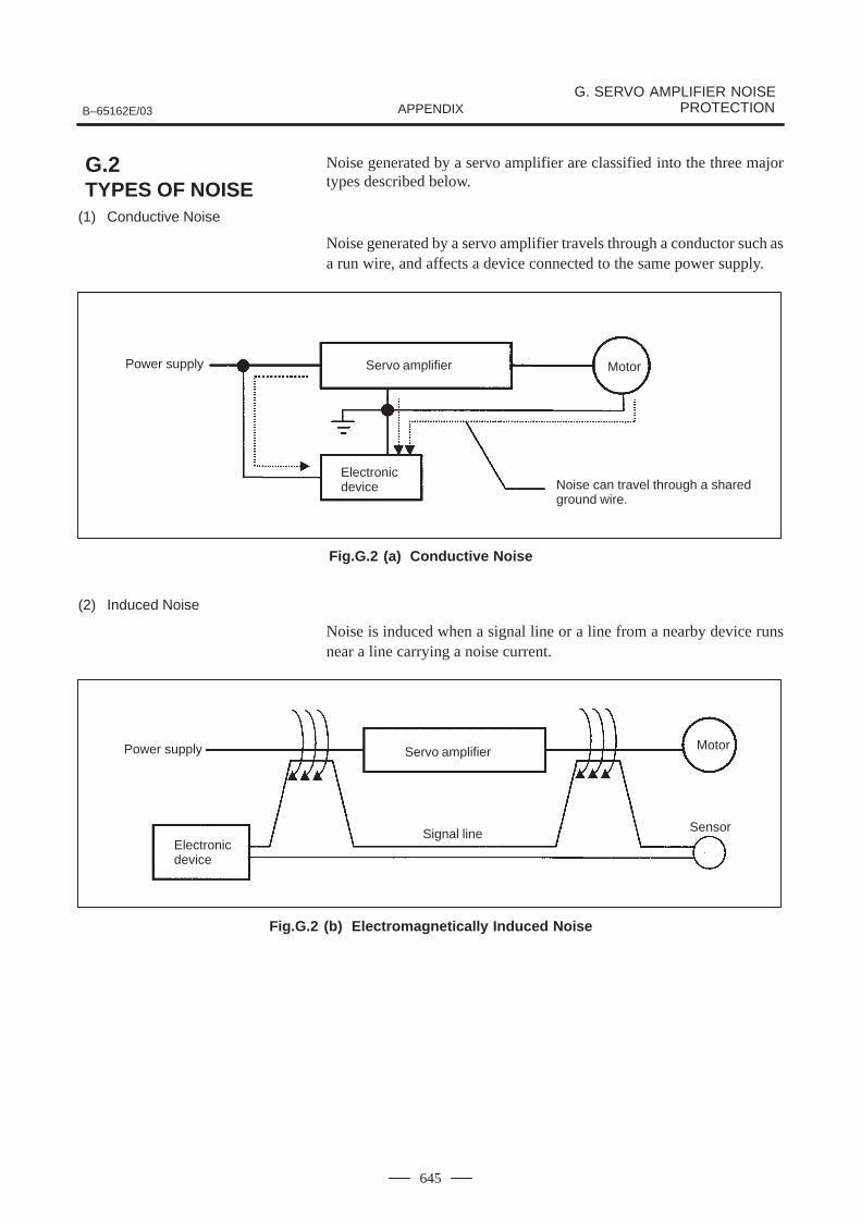
B–65162E/03
G. SERVO AMPLIFIER NOISEPROTECTIONAPPENDIX
645
Noise generated by a servo amplifier are classified into the three majortypes described below.
(1) Conductive Noise
Noise generated by a servo amplifier travels through a conductor such asa run wire, and affects a device connected to the same power supply.
Power supply Servo amplifier Motor
Electronicdevice Noise can travel through a shared
ground wire.
Fig.G.2 (a) Conductive Noise
(2) Induced Noise
Noise is induced when a signal line or a line from a nearby device runsnear a line carrying a noise current.
Power supply Servo amplifier Motor
Electronicdevice
SensorSignal line
Fig.G.2 (b) Electromagnetically Induced Noise
G.2TYPES OF NOISE
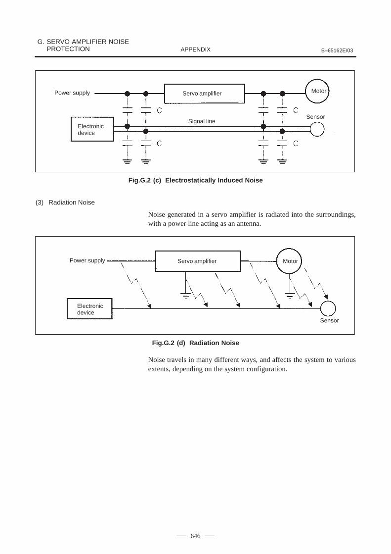
G. SERVO AMPLIFIER NOISE PROTECTION B–65162E/03APPENDIX
646
Power supply Servo amplifier Motor
Electronicdevice
SensorSignal line
Fig.G.2 (c) Electrostatically Induced Noise
(3) Radiation Noise
Noise generated in a servo amplifier is radiated into the surroundings,with a power line acting as an antenna.
Power supply Servo amplifier Motor
Sensor
Electronicdevice
Fig.G.2 (d) Radiation Noise
Noise travels in many different ways, and affects the system to variousextents, depending on the system configuration.
B–65162E/03
G. SERVO AMPLIFIER NOISEPROTECTIONAPPENDIX
647
Present–day technology cannot eliminate noise completely. So,cost–effective measures must be applied, depending on the level of thenoise and the status of the installation.
If a noise problem is detected after installation, more costs may be incurredto solve the problem. So, the following precautions must be applied:
1 Separate power lines and motor power lines from signal lines.
2 Contain power lines and motor power lines in a metallic conduit.
3 Perform appropriate grounding installation including groundingwire connections. (This also serves as a measure against electricshock due to leakage currents.)
4 Grounding wires should be as thick and short as possible.
The electric installation standard defines types of grounding as follows:
Type of grounding Application Ground resistance
Class–3 grounding 300VAC or less 100Ω or less
Special class–3 grounding 300VAC to 600VAC 10Ω or less
Noise–related measures including those for devices affected by noise,must be applied from the viewpoint of the entire system.
(1) Measures to be applied to a device affected by noise
1 Separate the power lines and motor power lines from the signallines to minimize the influence of noise.
2 Separate the power supply system to eliminate any noisepropagation path.
3 Run the signal lines through ferrite core beads to maximize theimpedance against noise.
4 Employ line filters and shielding wires for the signal lines toprotect against noise.
(2) Measures to be applied to a noise source
1 Reduce the level of noise by installing a noise protective devicesuch as a noise filter.
2 Confine noise by running the lines in metallic conduits or byusing shielding wires.
3 Eliminate any noise propagation path by using an insulatingtransformer.
(3) Measures specific to each type of noise
The types of noise are described in G.2 above. Different measuresshould be taken for each type of noise. The measures and their effectsdepend on the environment (power supply, electromagnetic wavestrength), machine operating status, machine anti–noise properties,and so forth.
G.3NOISE PROTECTION
G.3.1Precautions to beApplied Prior toInstallation
G.3.2Measures

G. SERVO AMPLIFIER NOISE PROTECTION B–65162E/03APPENDIX
648
Apply the most efficient measures as described in Table G.3.2
Table.G.3.2 Measures Specific to Each Type of Noise
Type of noise Conduc- Induced Radiationyp
MeasuresConductive noise
Inducednoise
Radiationnoise
Separation of power lines and motor power lines fromsignal lines
Use of metallic conduits
Wiring and grounding Elimination of parallel wiring
Employing shielded wires for power lines and motorpower lines
Secure grounding
Noise protective device Line filter Noise rotective device (at noise source) Insulating transformer
Noise protective device Running signal lines through ferrite core beads Noise rotective device (on devices affected by noise) Employing shielded wires for signal lines
Others Power system separation
(1) AM Radio
<<Symptoms>>When a motor is activated, radios in the plant pick up noise, such thatthe radio output becomes inaudible.
<<Possible causes>>Radiation noise from the motor power line connected to a servoamplifier is being picked up by the radios.
<<Measures>>
1 Install a noise filter (LC filter) on the power supply.
2 Install a capacitor between each input phase and ground.
<<Notes>> The measures described above may prove ineffective in some
areas, such as dense residential areas and mountain areas, whereradio signals are weak.
When installing a noise filter, minimize the length of the wiringbetween the filter and servo amplifier.
(2) FM Radio
<<Symptoms>>When the machine is operated, radios in the neighborhood areaffected by noise. A radio in a car parked outside the plant also picksup noise.
G.3.3Examples of NoiseProtection
B–65162E/03
G. SERVO AMPLIFIER NOISEPROTECTIONAPPENDIX
649
<<Possible causes>>The transformer on a utility pole is shared by neighbors, and noise isbeing radiated from the power supply wiring. Noise may also beconducted through the power supply line.
<<Measures>>
1 Install a noise filter (LC filter) on the power supply.
2 Feed power to the neighbors from a separate utility pole.
<<Notes>> When installing a noise filter, minimize the length of the wiring
between the filter and servo amplifier.
(3) Refrigerator
<<Symptoms>>When the spindle rotation is decelerated, the motor of a refrigeratorin the neighborhood makes an abnormal sound.
<<Possible causes>>The transformer on a utility pole is shared by neighbors, and voltagedistortion is caused by power regeneration at spindle deceleration.
<<Measures>>
1 Feed power to the neighbors from a separate utility pole.
2 Review the power supply capacity.
<<Notes>> A plant located in a dense residential area often takes its power
from a utility pole that also supplies power to neighboring houses(light power sharing), such that the power supply capacity of thesystem may be insufficient. In such a case, a larger powerdistortion may result, thus affecting the power being fed toneighboring houses.
(4) Telephone
<<Symptoms>>When the machine is operated, the telephone of a house across thestreet is affected by noise.
<<Possible causes>>When a high–frequency current from the servo amplifier or motorreturns through the ground of the transformer of the utility pole, itflows through the ground shield of the telephone line, generatingnoise by electrostatic induction.
<<Measures>>
1 Feed power to the neighbors from a separate utility pole.
2 Insert a capacitor on the grounding wire on the servo amplifierpower supply side.
<<Notes>> Noise consists of voice frequency components, so that a noise
filter (LC filter) may have no effect. Inserting a capacitor on a grounding wire increases the leakage
current, so that the ground fault interrupter may function.
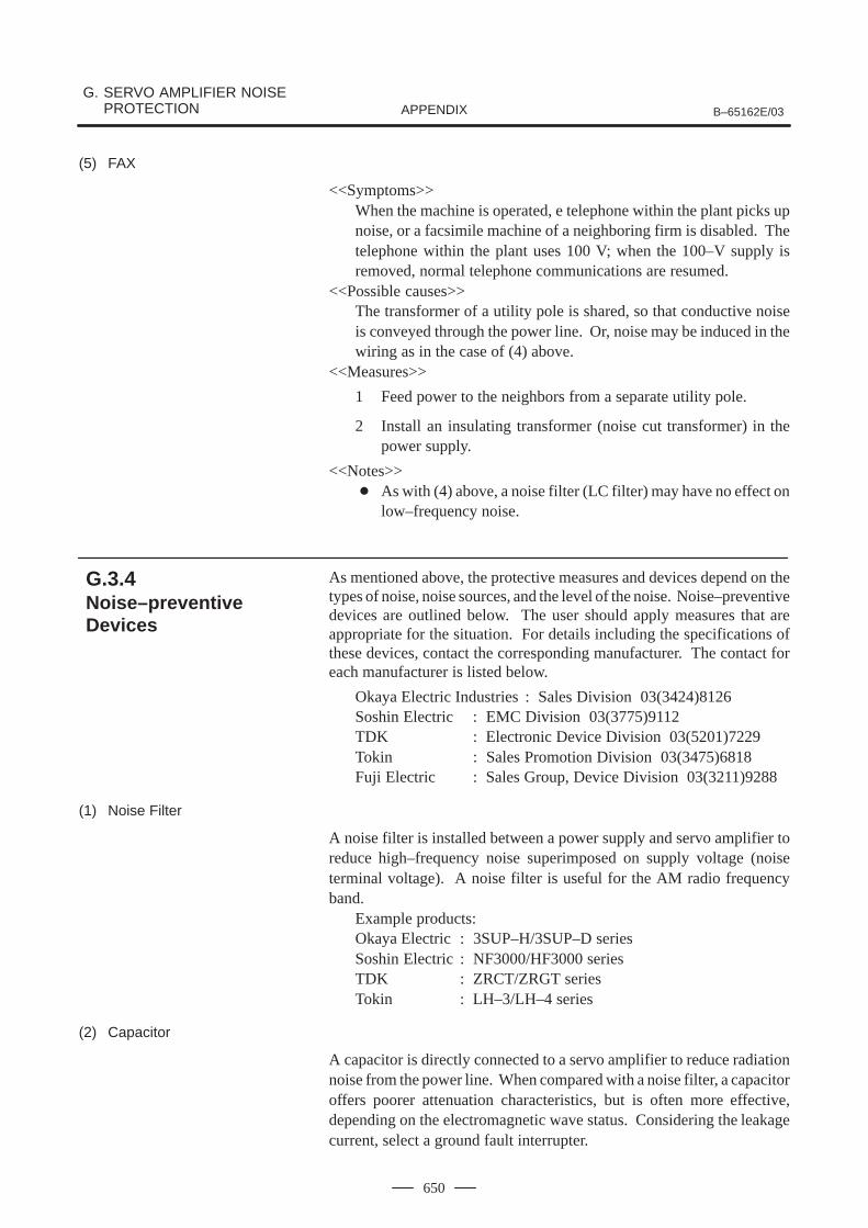
G. SERVO AMPLIFIER NOISE PROTECTION B–65162E/03APPENDIX
650
(5) FAX
<<Symptoms>>When the machine is operated, e telephone within the plant picks upnoise, or a facsimile machine of a neighboring firm is disabled. Thetelephone within the plant uses 100 V; when the 100–V supply isremoved, normal telephone communications are resumed.
<<Possible causes>>The transformer of a utility pole is shared, so that conductive noiseis conveyed through the power line. Or, noise may be induced in thewiring as in the case of (4) above.
<<Measures>>
1 Feed power to the neighbors from a separate utility pole.
2 Install an insulating transformer (noise cut transformer) in thepower supply.
<<Notes>> As with (4) above, a noise filter (LC filter) may have no effect on
low–frequency noise.
As mentioned above, the protective measures and devices depend on thetypes of noise, noise sources, and the level of the noise. Noise–preventivedevices are outlined below. The user should apply measures that areappropriate for the situation. For details including the specifications ofthese devices, contact the corresponding manufacturer. The contact foreach manufacturer is listed below.
Okaya Electric Industries : Sales Division 03(3424)8126Soshin Electric : EMC Division 03(3775)9112TDK : Electronic Device Division 03(5201)7229Tokin : Sales Promotion Division 03(3475)6818Fuji Electric : Sales Group, Device Division 03(3211)9288
(1) Noise Filter
A noise filter is installed between a power supply and servo amplifier toreduce high–frequency noise superimposed on supply voltage (noiseterminal voltage). A noise filter is useful for the AM radio frequencyband.
Example products: Okaya Electric : 3SUP–H/3SUP–D series Soshin Electric : NF3000/HF3000 series TDK : ZRCT/ZRGT series Tokin : LH–3/LH–4 series
(2) Capacitor
A capacitor is directly connected to a servo amplifier to reduce radiationnoise from the power line. When compared with a noise filter, a capacitoroffers poorer attenuation characteristics, but is often more effective,depending on the electromagnetic wave status. Considering the leakagecurrent, select a ground fault interrupter.
G.3.4Noise–preventiveDevices
B–65162E/03
G. SERVO AMPLIFIER NOISEPROTECTIONAPPENDIX
651
Example products : Okaya Electric : 3XYB–105 104Soshin Electric : LW3/LY3 series
(3) Zero–phase reactor
A zero–phase reactor is installed between a power supply and servoamplifier to reduce the amount noise being radiated from the power line.
Example product:Soshin Electric : RC series
(4) Noise Cut Transformer
A noise cut transformer is installed between a power supply and device.This transformer is used to reduce the amount of radiation noise (lowfrequency) being conveyed through a power line or ground wire.
Example product:Fuji Electric : FFT series
G. SERVO AMPLIFIER NOISE PROTECTION B–65162E/03APPENDIX
652
Harmonics and noise
A harmonic has an integral multiple of a fundamental frequency (50/60Hz), usually, up to several kHz; a higher frequency (several kHz or higher)is referred to as noise.In many cases, noise is generated from an inverter section, whileharmonics are generated from a converter section. Accordingly, thesediffer in the problems they incur and the corresponding countermeasures.For harmonics, a harmonics suppression guideline has been established.
G.4OTHERS
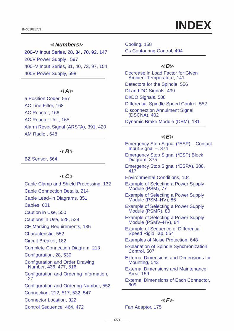
INDEXB–65162E/03
653
Numbers
200–V Input Series, 28, 34, 70, 92, 147
200V Power Supply , 597
400–V Input Series, 31, 40, 73, 97, 154
400V Power Supply, 598
A
a Position Coder, 557
AC Line Filter, 168
AC Reactor, 166
AC Reactor Unit, 165
Alarm Reset Signal (ARSTA), 391, 420
AM Radio , 648
B
BZ Sensor, 564
C
Cable Clamp and Shield Processing, 132
Cable Connection Details, 214
Cable Lead–in Diagrams, 351
Cables, 601
Caution in Use, 550
Cautions in Use, 528, 539
CE Marking Requirements, 135
Characteristic, 552
Circuit Breaker, 182
Complete Connection Diagram, 213
Configuration, 28, 530
Configuration and Order DrawingNumber, 436, 477, 516
Configuration and Ordering Information,27
Configuration and Ordering Number, 552
Connection, 212, 517, 532, 547
Connector Location, 322
Control Sequence, 464, 472
Cooling, 158Cs Contouring Control, 494
D
Decrease in Load Factor for GivenAmbient Temperature, 141
Detectors for the Spindle, 556DI and DO Signals, 499DI/DO Signals, 508Differential Spindle Speed Control, 552Disconnection Annulment Signal
(DSCNA), 402Dynamic Brake Module (DBM), 181
EEmergency Stop Signal (*ESP) – Contact
Input Signal –, 374Emergency Stop Signal (*ESP) Block
Diagram, 375Emergency Stop Signal (*ESPA), 388,
417Environmental Conditions, 104Example of Selecting a Power Supply
Module (PSM), 77Example of Selecting a Power Supply
Module (PSM–HV), 86Example of Selecting a Power Supply
Module (PSMR), 80Example of Selecting a Power Supply
Module (PSMV–HV), 84Example of Sequence of Differential
Speed Rigid Tap, 554Examples of Noise Protection, 648Explanation of Spindle Synchronization
Control, 507External Dimensions and Dimensions for
Mounting, 543External Dimensions and Maintenance
Area, 159External Dimensions of Each Connector,
609
FFan Adaptor, 175
B–65162E/03INDEX
654
Features, 435, 451, 476
Feedback Cable Length, 622
Fitting a Lightning Surge ProtectionDevice, 596
Frequency Arrival Signal (SARA), 424
Frequency Detecting Signal (SDTA), 423
Frequency–stop Detecting Signal (SSTA),422
G
Ground, 110
H
Heat Dissipation, 146
High–resolution Magnetic Pulse Coder,572
High–resolution Position Coder , 559
High–speed Orientation , 446
How to Select the Power Supply Module,67, 79
How to Select the Power Supply Module(PSM), 75
How to Select the Servo AmplifierModule, 68
IInput Power, 106
Input Power and Grounding, 106
Installation, 103, 597
Interface Signals, 373
LLeakage Current, 109
Lightning Surge Protector, 191
List of Motor Output Capacities for PowerSupply Selection, 87
Load Detection Signal (LDT1A, LDT2A),397
Load Detection Signal (LDTA), 425
Load Meter Voltage (LM), 405
M
Machine Ready Signal (MRDYA), 388,418
Magnetic Contactors, 184Magnetic Sensor (for Orientation), 580Magnetic Sensor Method Spindle
Orientation, 476Maintenance Areas, 211Maximum Output Capacity of Power
Supply Module, 75Maximum Output Capacity of Power
Supply Module (PSMR), 79Measures, 647Motor Power Off Signal (MPOFA), 401,
428Mounting Conditions and Notes, 562
N
Noise Prevention, 131Noise Protection, 647Noise–preventive Devices, 650Normal Rotation Command Signal
(SFRA), 389, 419Notes, 476, 599Notes on Amplifier Installation Related to
Safety Standards, 137Notes on the Emergency Stop Circuit
Configuration, 140Number of Connected Servo Amplifier
Modules and Spindle Amplifier Modules, 76, 79, 86
O
Obtaining the Maximum Output Capacityof a Power Supply Module, 85
Obtaining the Rated Output Capacity of aPower Supply Module, 85
Option Related to Spindle, 434Ordering Information, 34Other Detectors, 572
INDEXB–65162E/03
655
Outline Drawings, 160
Outline Drawings of Modules, 160
Output Frequency Display Signal (SM)(Usable as Load Meter Voltage SignalAccording to Parameter Setting), 429
PPanel Cut–out Diagrams, 194
Parameter List, 459, 473, 491
Parameters, 445, 466, 483, 501, 514,528, 539, 555
Position Coder Methed SpindleOrientation (αC Series Spindle), 435
Position Coders, 557
Power Supply Module, 22, 92, 97, 147,322
Power Supply Module ConnectionDiagram, 214
Power Supply Modules, 101, 154, 351
Power Transformer, 169
Precautions to be Applied Prior toInstallation, 647
Protecting External Electronic Devicesfrom Noise, 135
Protection Against Electric Shock, 139
Protective Installation, 140
R
Rated Output Capacity, 75
Rated Output Capacity (PSMR), 79
Regenerative Discharge Unit, 178
Restrictions, 531
Reverse Rotation Command Signal(SRVA), 390, 420
Rigid Tapping, 484
SSample Sequence, 500, 511
Selecting a Noise Filter, 136
Selecting a Power Supply Module(PSM–HV), 85
Selecting a Power Supply Module(PSMV–HV), 84
Selecting a Power Supply Module Whenthe Machining Cycle Frequency is High,76
Selecting a Regenerative Discharge Unit,81
Selecting a Spindle Amplifier Module, 74
Separation of Signal Lines, 131
Sequence, 457, 490, 524, 537
Sequence for Emergency Stop, 376
Sequence for Releasing EmergencyStop, 377
Sequences, 443, 481
Servo Amplifier Module, 24, 149, 327
Servo Amplifier Module (SVM), 94
Servo Amplifier Module (SVM–HV), 99
Servo Amplifier Module ConnectionDiagram, 244
Servo Amplifier Modules, 102, 156, 356
Servo Amplifier Noise Generation, 644
Servo Amplifier Noise Protection, 643
Servo Cable Length (whenRecommended Cables are Used), 624
Servo Motor, 87
Signal Explanation, 439, 478, 553
Signal For Controlling Velocity Integration(INTGA), 398
Signals, 453, 462, 470, 487
Soft Start Stop Cancel Signal (SOCAN),398
Specification No., 541
Specification of the External One–rotationSignal Switch, 474
Specifications, 91, 438, 453, 468, 478,498, 516, 531, 542
Specifications of Cables, 625
Specifications of the Position CoderSignal, 553
Speed Arrival Signal (SARA), 395
Speed Detecting Signal (SDTA), 393
B–65162E/03INDEX
656
Speed Integral Control Signal (INTGA),426
Speed Meter Voltage Signal (SM), 404
Speed Range Switching Control, 516
Spindle Alarm Signal (ALMA), 391, 421
Spindle Amplifier Module, 25, 96, 100,102, 152, 157, 342, 364
Spindle Amplifier Module ConnectionDiagram, 276
Spindle Amplifier Output Signals (αSeries Spindles), 404
Spindle Amplifier Output Signals (αCSeries Spindle), 429
Spindle Analog Override Command(OVRA), 427
Spindle Cable Length (whenRecommended Cables are Used), 623
Spindle Control DI Signal (PMC to CNC),379, 411
Spindle Control DO Signals (CNC toPMC), 384, 415
Spindle Control Signals, 520, 534
Spindle Control Signals (α seriesspindle), 378
Spindle Control Signals (αC SeriesSpindle), 410
Spindle Motor, 89
Spindle Orientation, 435
Spindle Orientation by External OneRotation Signal, 466
Spindle Orientation of IncrementalCommand Type (Spindle SpeedControl), 460
Spindle Orientation of Position CoderType (aC Series), 450
Spindle Override Command (Function)With Analog Input Voltage (OVRA), 399
Spindle Switching Control, 530
Spindle Synchronization Control, 504
Standard Class of Insulation Design, 137
Summary of Amp Connectors, 600
SWITCHING UNIT, 541
System Configuration, 452, 467, 484,495, 504
System Configurations, 461
TTorque Limiting Command Signal
(TLMHA) (Under development), 420
Torque Limiting Command Signal(TLMLA, TLMHA), 390
Types of Noise, 645
W
Weight, 101
ZZero–speed Detecting Signal (SSTA),
392
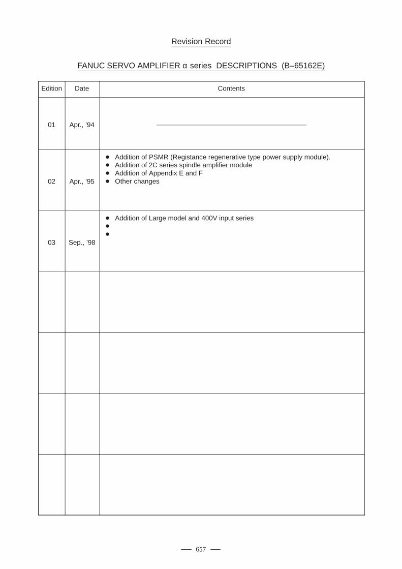
657
Revision Record
FANUC SERVO AMPLIFIER α series DESCRIPTIONS (B–65162E)
Edition Date Contents
01 Apr., ’94
02 Apr., ’95
Addition of PSMR (Registance regenerative type power supply module). Addition of 2C series spindle amplifier module Addition of Appendix E and F Other changes
03 Sep., ’98
Addition of Large model and 400V input series

No part of this manual may bereproduced in any form.
All specifications and designs aresubject to change without notice.

FANUC LTD
Printed in Japan


