FAQ_Near Field Probes V1.0.docx V1.0 FAQ Tekbox Near Field Probes Author: Mayerhofer 1 of 13 TekBox Digital Solutions 10-Jun-19 Index 1 How to calculate the magnetic and electric field ........................................................... 2 2 How to measure RF-currents........................................................................................ 2 3 Phase linearity .............................................................................................................. 7 4 Probe performance at low frequencies ......................................................................... 9 5 History ........................................................................................................................ 13
Transcript
FAQ_Near Field Probes V1.0.docx V1.0
FAQ Tekbox Near Field Probes
Author: Mayerhofer 1 of 13 TekBox Digital Solutions 10-Jun-19
Index
1 How to calculate the magnetic and electric field ........................................................... 2
2 How to measure RF-currents ........................................................................................ 2
4 Probe performance at low frequencies ......................................................................... 9
5 History ........................................................................................................................ 13
FAQ_Near Field Probes V1.0.docx V1.0
FAQ Tekbox Near Field Probes
Author: Mayerhofer 2 of 13 TekBox Digital Solutions 10-Jun-19
1 How to calculate the magnetic and electric field Near field probes are primarily designed for EMC probing. Probes dedicated for electric and magnetic field measurements are designed differently. They are based on small dipoles with integrated power detectors. They are often supplied via glass fiber and built symmetrically to minimize distortion of the field. EMC sniffer probes can be used to measure the magnetic or electric field, but be aware that the handle will cause distortions of the field and consequently degraded accuracy of the measurement. H-Field Probes:
𝐵 = 10(𝑃𝑜𝑢𝑡−𝑆−20 log10 𝐹)
20 Where B is the magnetic flux density, in Tesla F is the frequency of the received signal, in megahertz Pout is the probe output power into 50 ohms, in dBm S is a scaling factor, depending on the probe H20: S = 76 H10: S = 56 H5: S = 47 E-field probe E5:
𝐸 = 10(𝑃𝑜𝑢𝑡+112.5−20 log10 𝐹)
20 Where E is the electric field strength, in V/m F is the frequency of the received signal, in megahertz Pout is the probe output power into 50 ohms, in dBm 112.5 is the scaling factor for the E5 probe
Also refer to the excel sheet TBPS1.xls, which you can download from our web site
2 How to measure RF-currents
How can the output signal of the probes be converted into RF current? Though the H-field probes are not a substitute for dedicated RF current monitoring probes, they can be used to measure RF currents. The following table contains the frequency dependent trans-impedance of the H20, H10 and H5 near field probes. The trans-impedance values were measured with the probes placed directly on the surface of a 50 Ohm microstripline and include the loss of the supplied RG316 cable. Note that the probes must be oriented with their flat side in line with the microstripline (PCB trace) or wire under investigation. In contrary to dedicated RF current monitoring probes, in case of H-field probes, the wire under investigation shall not be fed through the opening of the probe.
RF-current [dBµA] = Probe Output Power [dBm] + 107 – transimpedance factor [dBΩ] The frequency and probe-dependent trans-impedance values can be found in the table below.
FAQ_Near Field Probes V1.0.docx V1.0
FAQ Tekbox Near Field Probes
Author: Mayerhofer 3 of 13 TekBox Digital Solutions 10-Jun-19
Picture 1: Correct positioning of the H-field probe Transimpedance Table:
Author: Mayerhofer 4 of 13 TekBox Digital Solutions 10-Jun-19
850 5.28 6.88 1.68
875 5.28 6.88 1.98
900 5.28 6.88 2.18
925 5.28 6.48 2.38
950 5.28 6.78 2.58
975 5.28 6.78 2.68
1000 5.28 6.78 2.78
1025 5.18 6.88 2.98
1050 4.88 6.98 3.08
1075 4.58 6.98 3.08
1100 4.38 7.18 2.98
1125 4.08 7.48 3.18
1150 3.68 7.68 3.38
1175 3.28 7.78 3.58
1200 2.88 7.88 3.68
1225 2.18 7.88 3.88
1250 1.18 7.88 4.18
1275 0.08 7.88 4.28
1300 -0.42 7.78 4.48
1325 1.58 7.68 4.58
1350 5.38 7.58 4.68
1375 9.48 7.48 4.78
1400 11.58 7.48 4.78
1425 11.68 7.38 4.68
1450 10.78 7.38 4.68
1475 9.88 7.28 4.48
1500 9.48 7.38 4.38
1525 8.88 7.48 4.38
1550 8.48 7.58 4.48
1575 7.68 7.68 4.58
1600 7.68 7.68 4.88
1625 7.28 7.78 5.18
1650 6.88 7.68 5.38
1675 6.38 7.48 5.58
1700 5.88 7.28 5.68
1725 5.48 6.98 5.68
1750 5.18 6.78 5.78
1775 4.98 6.48 5.68
1800 4.88 6.48 5.58
1825 4.78 6.48 5.58
1850 4.58 6.38 5.58
1875 4.58 6.38 5.38
1900 4.48 6.48 5.28
1925 4.38 6.68 5.28
1950 4.18 6.78 5.38
1975 3.88 6.78 5.38
2000 3.48 6.68 5.28
2025 3.08 6.58 5.38
2050 2.68 6.28 5.38
2075 2.48 5.98 5.28
2100 2.28 5.78 5.18
2125 1.88 5.48 5.08
2150 1.68 5.08 4.88
2175 1.58 4.98 4.58
2200 1.58 4.98 4.48
2225 1.48 5.08 4.38
2250 1.28 5.08 4.28
2275 1.08 5.08 4.18
2300 0.98 5.38 4.18
2325 0.88 5.78 4.48
2350 0.68 5.88 4.68
2375 0.58 5.78 4.78
2400 0.48 5.68 4.98
2425 0.48 5.38 5.38
2450 0.58 4.98 5.58
2475 0.88 4.48 5.48
2500 0.48 3.88 5.28
2525 0.78 3.48 5.18
FAQ_Near Field Probes V1.0.docx V1.0
FAQ Tekbox Near Field Probes
Author: Mayerhofer 5 of 13 TekBox Digital Solutions 10-Jun-19
2550 0.68 2.98 4.98
2575 1.08 2.58 4.68
2600 1.18 2.58 4.38
2625 0.98 2.68 4.18
2650 0.68 2.58 4.08
2675 0.48 2.68 4.08
2700 0.28 3.18 4.18
2725 -0.22 3.78 4.68
2750 -0.42 3.98 4.98
2775 -0.62 4.08 5.08
2800 -0.62 4.28 5.48
2825 -0.62 4.28 5.88
2850 -0.32 3.98 6.08
2875 0.18 3.48 5.98
2900 0.48 2.98 5.78
2925 0.78 2.38 5.68
2950 1.18 1.68 5.38
2975 1.68 0.88 5.08
3000 1.98 0.48 4.58
3025 2.98 -0.12 4.38
3050 1.78 -0.82 4.08
3075 1.58 -1.52 3.78
3100 1.38 -1.82 3.68
3125 0.98 -1.92 3.88
3150 0.88 -1.92 4.18
3175 1.08 -1.22 4.58
3200 1.58 0.68 5.08
3225 2.28 3.28 5.78
3250 3.18 5.88 6.48
3275 4.18 8.08 6.78
3300 5.08 9.38 6.88
3325 5.98 9.78 6.88
3350 6.78 9.48 6.78
3375 7.28 8.88 6.38
3400 7.58 8.18 5.88
3425 7.68 7.78 5.38
3450 7.58 7.38 5.18
3475 7.48 6.88 4.78
3500 7.58 6.68 4.58
3525 7.88 6.78 4.58
3550 8.18 6.98 4.68
3575 8.38 6.98 4.78
3600 8.48 7.08 4.88
3625 8.38 7.18 5.08
3650 8.18 7.28 5.48
3675 7.78 7.08 5.58
3700 7.28 6.68 5.48
3725 6.38 6.38 5.28
3750 5.38 6.08 5.08
3775 4.58 5.68 4.78
3800 3.58 5.48 4.28
3825 2.48 5.38 3.88
3850 1.28 5.48 3.78
3875 0.18 5.48 3.68
3900 -0.82 5.58 3.58
3925 -1.92 5.98 3.58
3950 -2.82 6.28 3.78
3975 -3.52 6.48 3.98
4000 -3.92 6.58 4.18
4025 -4.12 6.78 4.38
4050 -4.52 6.98 4.68
4075 -4.32 6.58 4.78
4100 -3.82 6.28 4.78
4125 -3.02 5.98 4.78
4150 -2.12 5.58 4.78
4175 -1.02 5.08 4.48
4200 0.38 4.58 3.88
4225 1.78 4.58 3.58
FAQ_Near Field Probes V1.0.docx V1.0
FAQ Tekbox Near Field Probes
Author: Mayerhofer 6 of 13 TekBox Digital Solutions 10-Jun-19
4250 2.98 4.58 3.48
4275 3.98 4.48 3.38
4300 4.88 4.38 2.98
4325 5.48 4.58 2.68
4350 5.88 5.08 3.08
4375 6.18 5.28 3.38
4400 6.38 5.38 3.48
4425 6.48 5.38 3.58
4450 6.78 5.48 3.98
4475 7.28 5.48 4.28
4500 7.78 5.28 4.48
4525 7.88 4.78 4.48
4550 8.08 4.28 4.28
4575 8.38 3.68 3.98
4600 8.78 3.28 3.58
4625 9.18 3.18 3.08
4650 9.28 3.18 2.78
4675 9.28 2.98 2.48
4700 9.28 2.88 1.98
4725 9.28 3.18 1.78
4750 9.28 3.68 1.78
4775 9.28 4.08 1.98
4800 9.28 4.38 2.18
4825 9.28 4.78 2.38
4850 9.38 5.18 2.88
4875 9.68 5.48 3.48
4900 9.98 5.48 3.88
4925 10.08 5.48 4.18
4950 10.08 5.38 4.48
4975 10.18 5.08 4.48
5000 10.38 4.68 4.48
5025 10.48 4.48 4.28
5050 10.48 4.28 4.18
5075 10.38 4.08 3.88
5100 10.18 3.68 3.38
5125 9.88 3.68 2.88
5150 9.78 5.58 2.78
5175 9.68 5.08 2.78
5200 9.38 4.58 2.58
5225 8.98 4.78 2.38
5250 8.58 5.08 2.38
5275 8.58 5.48 2.78
5300 8.58 5.88 3.18
5325 8.38 6.08 3.38
5350 7.98 5.98 3.48
5375 7.58 5.78 3.58
5400 7.58 5.78 3.78
5425 7.68 5.78 3.98
5450 7.58 5.68 3.98
5475 7.38 5.28 3.58
5500 7.28 4.88 3.08
5525 7.28 4.88 2.78
5550 7.48 5.28 2.88
5575 7.28 5.28 2.68
5600 6.78 5.08 2.18
5625 6.38 4.88 1.58
5650 6.28 5.18 1.38
5675 6.38 5.68 1.68
5700 6.38 6.18 1.88
5725 5.98 6.08 1.68
5750 5.48 5.98 1.58
5775 5.38 5.98 1.68
5800 5.58 6.18 2.08
5825 5.38 6.38 2.28
5850 5.48 6.08 2.08
5875 5.08 5.48 1.58
5900 5.18 5.38 1.28
5925 5.48 5.68 1.28
FAQ_Near Field Probes V1.0.docx V1.0
FAQ Tekbox Near Field Probes
Author: Mayerhofer 7 of 13 TekBox Digital Solutions 10-Jun-19
5950 5.78 5.98 1.38
5975 5.68 5.88 1.18
6000 5.38 5.38 0.78
Table 1: trans-impedance
Also refer to the excel sheet TBPS1.xls, which you can download from our web site
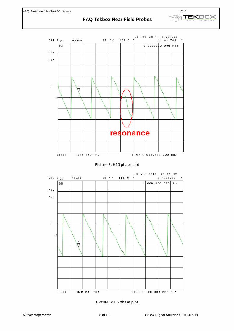
3 Phase linearity
We want to use the probes to measure high speed pulses on traces in the time domain. Is the probe phase linear? The probe phase is perfectly linear below the resonance frequency. H20 has two resonances in the frequency range up to 6 GHz. H10 has one resonance in the frequency range up to 6 GHz. H5 and E5 don´t have any resonance below 6 GHz.
Picture 2: H20 phase plot
FAQ_Near Field Probes V1.0.docx V1.0
FAQ Tekbox Near Field Probes
Author: Mayerhofer 8 of 13 TekBox Digital Solutions 10-Jun-19
Picture 3: H10 phase plot
Picture 3: H5 phase plot
FAQ_Near Field Probes V1.0.docx V1.0
FAQ Tekbox Near Field Probes
Author: Mayerhofer 9 of 13 TekBox Digital Solutions 10-Jun-19
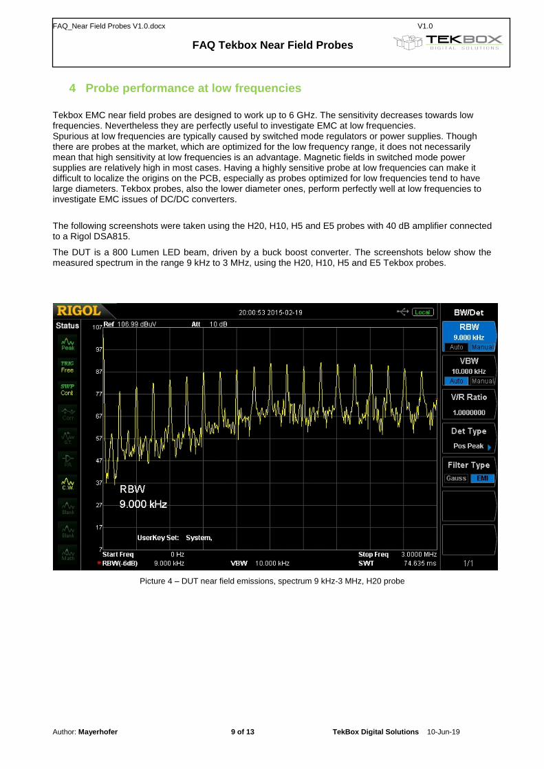
4 Probe performance at low frequencies
Tekbox EMC near field probes are designed to work up to 6 GHz. The sensitivity decreases towards low frequencies. Nevertheless they are perfectly useful to investigate EMC at low frequencies. Spurious at low frequencies are typically caused by switched mode regulators or power supplies. Though there are probes at the market, which are optimized for the low frequency range, it does not necessarily mean that high sensitivity at low frequencies is an advantage. Magnetic fields in switched mode power supplies are relatively high in most cases. Having a highly sensitive probe at low frequencies can make it difficult to localize the origins on the PCB, especially as probes optimized for low frequencies tend to have large diameters. Tekbox probes, also the lower diameter ones, perform perfectly well at low frequencies to investigate EMC issues of DC/DC converters.
The following screenshots were taken using the H20, H10, H5 and E5 probes with 40 dB amplifier connected to a Rigol DSA815.
The DUT is a 800 Lumen LED beam, driven by a buck boost converter. The screenshots below show the measured spectrum in the range 9 kHz to 3 MHz, using the H20, H10, H5 and E5 Tekbox probes.
Picture 4 – DUT near field emissions, spectrum 9 kHz-3 MHz, H20 probe
FAQ_Near Field Probes V1.0.docx V1.0
FAQ Tekbox Near Field Probes
Author: Mayerhofer 10 of 13 TekBox Digital Solutions 10-Jun-19
Picture 5 – DUT near field emissions, spectrum 9 kHz-3 MHz, H10 probe
Picture 6 – DUT near field emissions, spectrum 9 kHz-3 MHz, H5 probe
FAQ_Near Field Probes V1.0.docx V1.0
FAQ Tekbox Near Field Probes
Author: Mayerhofer 11 of 13 TekBox Digital Solutions 10-Jun-19
Picture 7 – DUT near field emissions, spectrum 9 kHz-3 MHz, E5 probe
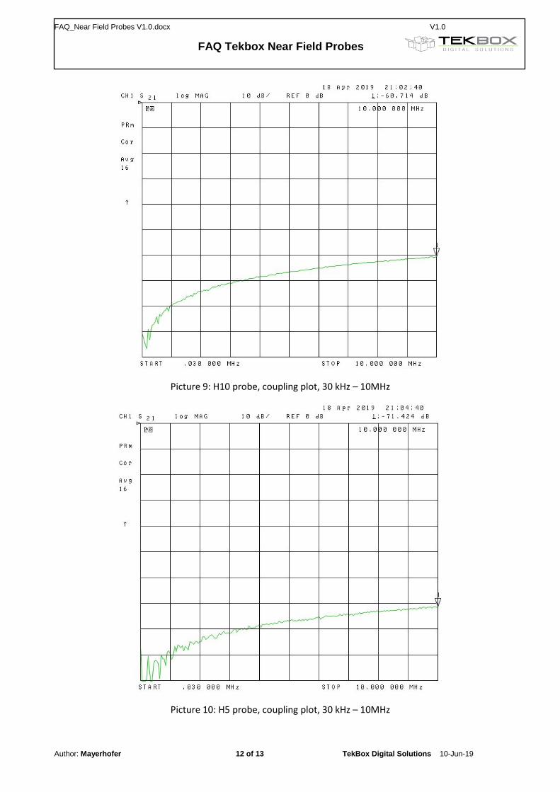
The coupling plots below show the performance of the near field probes at the low end of the frequency range: