Page | 1 INTRODUCTION TO NERFMTTI(ASSAM) By- Mr. Khagendra Bora Date - 04- july-2016 Northern Eastern Region Farm Machinery Training and Testing Institute (NERFMT&TI), Assam is not merely a name within the country among agricultural machinery institutions but a living culture. Transformation of this culture is the end result of untiring, dedicated and faithful services of a team of engineers, technicians and other personnel for the last thirty-eight years in the field of farm mechanization. The institute conducts training courses in operation, maintenance and repair of farm machinery and equipment, and in the improved mechanized farming techniques for the benefits of progressive farmers, tractor owners,
Transcript
P a g e | 1
INTRODUCTION TO NERFMTTI(ASSAM)
By- Mr. Khagendra Bora Date- 04-july-2016
Northern Eastern Region Farm Machinery Training and Testing Institute (NERFMT&TI), Assam is not merely a name within the country among agricultural machinery institutions but a living culture. Transformation of this culture is the end result of untiring, dedicated and faithful services of a team of engineers, technicians and other personnel for the last thirty-eight years in the field of farm mechanization. The institute conducts training courses in operation, maintenance and repair of farm machinery and equipment, and in the improved mechanized farming techniques for the benefits of progressive farmers, tractor owners, technicians, in-service personnel and foreign nationals sponsored under international co-operation programmes. Institute also conducts energy conservation and management camps and arrange training programmes for the women working in the field of agriculture. It is the official
P a g e | 2
institution in the country for the testing of combine harvesters, farm implements and machinery, irrigation pumps, stationery power engines and plant protection equipment.
LOCATION:
North bank of river Brahmaputra
Longitude range :- 92°16´ East -93°43´ East
Latitude Range :- 26°30´ North -27°01´ North
The institute located at about 275 kms. Aways from Guwahati and 4 kms from Bishwanath chariali centre on Bishwanath ghat road in Bishwanath chariali distt. & nearest airport is tezpur.
CLIMATE:
It lies in sub-tropical climatic region and enjoys monsoon type of climate summers are hot and humid, with an average temperature of 29°c .summer rain is heavy and its cause overflow and flood .Autumn are dry and warm.Winters are cold and dry w3ith average temperature of 16°.
HOW TO REACH:
The institute located at about 275 kms. Aways from Guwahati and 4 kms from Bishwanath chariali centre on Bishwanath ghat road in Bishwanath chariali dist. &Nearest Railway station is vishwanath chariali railway station , nearest airport is tezpur.
This training Centre is imparting training on the following courses:-
and Agriculture Implements, I.C. Engine, Irrigation Pumps, Plant Protection
Equipment, Straw & Grain Combine Harvesters etc.
2. Field practices on Tractor Operation with different matching implements.
P a g e | 3
1.Agricultural implements
a. MB plough
b. Disc plough
c. Harrows
d. Cultivators
e. seed drills
f. Transplanter
g. Planter
h. Reaper cum binder
i. Harvester
j. Combine harvester
h. Subsoiler
k. Side shifting rotavator
l. Chopper
m. Aero blast sprayer
n. Laser land leveller
0. Reaper binder
p. Ground nut digger
P a g e | 4
q. power weeder.
INTRODUCTION OF TRACTORTrainer:- Sh. A. Das (Sr. tech.) Date: 5-july-2016
Tractor:-
self-powered work vehicle, designed for pulling or pushing special machinery or heavy loads over land. Tractors are widely used in agriculture, building construction, and road construction, and for specialized service in industrial plants, railway freight stations, and docks. Applications also include snowplows and bulldozers ( Earth-Moving machine)
Types:-
There are two types of tractors: wheeled tractors, and crawler (track-laying) tractors. Wheeled tractors generally have two large rear wheels with pneumatic tires or ground-gripping metal lugs; they operate much like an automobile with a gearshift drive. Power is usually provided by a diesel or a gasoline engine. Crawler tractors are used for heavy pulling or pushing or for adverse terrain conditions. These tractors move on heavy, metal tracks that form a loop around large geared wheels; the wheels drive the metal tracks, and the tracks distribute the weight
P a g e | 5
over a wide area. Crawler tractors are well adapted to rough terrain, rice-land cultivation, and tillageoperations in loose and sandy soil. Lighter crawler tractors are frequently used for work on the sides of steep hills where they are less likely to overturn than wheeled tractors. The armored tank used in warfare is a military adaptation of the crawler tractor.
Uses:-
Farm tractors are used for plowing, cultivating, grading, or cutting, or for driving various agricultural machines.The use of tractors has revolutionized agriculture. The power capability of the modern tractor has led to higher productivity with a significantly reduced workforce. Early agricultural tractors were lumbering, heavy steam-engine vehicles moving on spiked or cleated metal wheels. These were rapidly replaced after the introduction of the general-purpose tractor in the 1920s, which by about 1933 featured the addition of pneumatic tires with rubber gripping lugs. The engine, in addition to providing pulling power, also drives a number of power take-off (PTO) shafts that can be used to operate accessory machinery. Large or special purpose tractors may also have a hydraulic power system that can be used to deploy or move various attachments such as bulldozer blades or snowplows. In recent years there has been a trend from four-wheeled to three-wheeled vehicles, where a single, central front wheel can operate more successfully among crops planted or cultivated in rows.
Crawler tractors are employed extensively in the building industry, where cranes or hoists are usually mounted directly on the tractor frame. The small, comparatively low-powered electric tractor, deriving its motor power from a storage battery, has been put to many specialized uses, such as handling freight and express material at railroad stations and steamship piers, and shifting material in large industrial plants and warehouses. Electric tractors are usually equipped with rubber-tired wheels. Other specialized tractors have been designed for numerous applications. For example, specialized tractors are used in mining operations, for many different forms of earth moving, and in the steel industry, where overhead tractors operate on tracks.
P a g e | 6
CHECKS DURING, PRE AND POST OPERATION OF TRACTOR
Trainer:- Sh A. Das(Sr.Tech.) Date: 5-july-2016 Sh B.Nath (Sr.Tech.)
Operation performed before starting a tractor:- 1. Fuel oil should be checked in the fuel tank. If it is not adequate, fuel oil
should be added to the tank.2. Lubricating oil should be checked, if necessary it should be topped up.3. Water in the radiator should be checked, if necessary it should be topped
up.4. Air cleaner should be checked to see whether it is clean or blocked. If
blocked, it should be cleaned.5. Transmission oil should be checked by a dipstick, if necessary it should be
topped up.6. Air pressure in the tyres should be checked and if necessary the tyres
should be inflated as recommended by the manufactures. 7. Fan belt should be checked by hand; if necessary it may be tightened or
loosened.8. Grease points should be checked, to see whether they have been greased
or not.9. Important nuts and bolts should be checked. If any of them are loose, it
should be tightened.10.The water level of the battery should be checked. If it is below the
partition wall, it should be filled up with distilled water.
P a g e | 7
Operation performed during operating a tractor:-
1. When some unusual sounds are heard in the tractor, it should be stopped immediately and the cause should be ascertained.
2. If the battery charging indicator does not show the charging current, the tractor should be stopped to find the cause.
3. If the oil pressure indicator does not show the normal pressure, the tractor should be stopped to find the cause.
4. If the temperature gauge is not showing normal temperature, the engine should be stopped to find the cause.
5. If the black smoke is continuously coming out of engine, the load should be decreased.
6. Gear should never be changed when the tractor is in motion.7. Always engage the clutch gently.8. While driving on roads both wheels are braked simultaneously.9. Reduce the speed before making a turn or applying the brakes.
Operation performed after operating a tractor:-1. After operating the tractor make use to stand it at the plane uniform
surface or land.2. Apply the parking brakes after stopping the tractor.3. Always lower down the all hitching implements after stopping the tractor.4. Turn off the main switch.
P a g e | 8
DRIVING OF TRACTORTrainer:- sh A. Das(Sr.Tech.) Date: 6-july-2016 Sh B.Nath(Sr. Tech.)
Method of starting a diesel tractor: -In order to start a tractor, the following sequence should be followed:
1. Always go up from left side of the tractor.2. Disengaged the parking brake.3. Put the gear shift lever and PTO lever into neutral position.4. Put the throttle lever in 3/4th position.5. Put the hydraulic control lever to the lowered position.6. Depress the clutch pedal and turn the starting key to the on position. Thus
the tractor will be started.
Safety Precaution during Tractor Driving:- The tractor must be trained or only trained person should be allowed
to drive tractor. Before moving the tractor trolley around, that any obstacles on the
road or any person between the tractor and the implement should be avoided.
No one allow that any person to climb the tractor while it moving. Even minor repairing work should not be done while engine is running. On slope land always lock the brake pedal when leaving the tractor and
also gear should be in the neutral position. The night temp. Should be in perfect working condition while tractor is
driving in night. On steep slope the tractor should be put in low gear at the same time
while coming down the slope the tractor should not in neutral gear. When the tractor is moving in high speed then sharp turning should be
avoided. The clutch pedal should be generally pressed and released.
P a g e | 9
The instruments on the control panel should be checked for their proper working.
Always follow the traffic rules while driving the tractor on the road.
Main practices of driving we have done:- Tractor moving forward and backward. Tractor moving with trolley forward and backward. Making “8” sign in forward and backward Proper hitching by implements to the tractor.
All these practice has done in first gear.Tractor provided to me:-
1. EICHER 2412. New Holland 30303. John Deere 53104. TAFE
These are the tractors which are provided to me. I was appointed on round “A” on 3030 new Holland.In the round ‘A’ I was only drive the tractor in L1 speed such as instructed to me by our instructor. Firstly I was sit on the tractor from left side and sited on the seat then I was check all the tractor necessary check-up’s which taught to me in the theory class. Then following operation was done by me:-Moving Tractor in forward direction:-For this operation I was started the tractor by the self starting device (key) then pressed the clutch of the tractor and then I put low gear and put 1st gear on the tractor.
Then I leave the press pedal of clutch slowly- slowly because if do not left the pedal, generally then the tractor will be jumped and it will be accidental. Well when I was left the tractor then tractor moving slowly-slowly forward direction. It was very challenging moment for me.
Moving Tractor in backward direction:-I was learning the gear shifting system in the previous operation. I was clutched the tractor when I putted on the neutral position then I was put it on the reverse gear then again put it on the L1 gear then pushed out the clutch.
P a g e | 10
When I was pushed out the clutch the tractor was started moving backward direction. In this operation we should careful but we do not take accelerator too much, and fully concentrate on the movement on the steering system.
Tractor Moving with trolley in forward & Backward Direction:-In the operation firstly we connect the trolley by the toe hook. Then I pressed the clutch & the change gear L1 forward direction. When I was left the tractor’s clutch then tractor was starting moving forward direction.
The main task is to move the tractor in the backward direction. When we move backward direction then we should noticed it that when trolley move to left side then we move the steering in left side, then trolley will move in right side and vice versa.
Making 8 by the tractor by (F+B):-It is done for the practice of the steering control. In this operation we move the tractor in line made 8-type track.This operation is done for the steering control and for fully control on the tractor.All these operations are done by all the tractors which were provided to me.
Method to stop a tractor:-Tractor is a heavy machine and it can cause serious accident if it is not stopped in time. The following procedure should be followed for stopping the movement of tractor.
1. Pull the throttle lever and reduce the engine speed to the lowest possible limit.
2. Decrease the clutch pedal and press the brake pedal of the tractor to stop the motion of the tractor.
3. Put the gear shift lever into neutral position.4. If an implement is attached to the tractor, hydraulic control lever should
be moved slowly to the lower position.5. Turn off the main switch.6. Apply the parking brakes, if necessary.
P a g e | 11
Maintenance of tractor: -The following are the main servicing & maintenance which is done in tractor:
1. Washing 2. Engine warm up 3. Oil draining 4. Oil filter change 5. Air cleaner oil change 6. Fan belt adjustment 7. Clutch free play adjustment 8. Break free play adjustment 9. Front wheel preloading 10.Greasing 11.Air pressure
Periodical maintenance of tractor:-
Daily (8to10) engine working hours:-1. Check oil level in oil sump if required then refill them and secure that tractor on the level surface.2. Clean and refill their cleaner bowl. In very dirty condition we check it move frequently and make sure that oil level does not move up by9.5mm above the recommended level mark.3. Inspect fuel sediment bowl for dirt or water and drain if necessary.4. Check the water level in the radiator.5. Check the belt pulley oil level and if necessary refill the same.6. Grease the front axle spindles and steering draglinks.7. Grease bearing of brake paddle assembly.8. Examine and fill up battery with distilled water if necessary.9. Check tyre pressure.
Weekly (50 to 60) engine working hours:-A. Engine -
Check fan belt tension
P a g e | 12
Check primary fuel filter deposit as well as for water accumulation, remove the sediments and water by opening the drain plug.
B. Transmission:- Check the correct oil level in the transmission box with the help of
dipstick provided and fills it if required.
C. Electrical:- Wipe battery with a clean cloth and grease terminals with
petroleum to prevent corrosion. Check tightness if securing strap’s of starter motor
After 15 days (120 to 125) engine working hours: -
1. Repeat the weekly schedule of maintenance.
2. Apply oil to the Dynamo and the starter.
3. Clean the carbon in the smoke-tube.
4. Change the engine oil.
5. In case the oil filter is made of paper, element, cloth, felt, etc. change them. Clean the metallic oil filter.
6. Check the free play of clutch and brake; it should be 15mm long. Adjust it according to the need.
Monthly (250) engine working hours: -
1. Repeat every step of 15 days maintenance.
2. If it is advised to clean the primary diesel filter, (in the manual supplied with the tractor) clean it or change it.
3. Wash the fuel filters and top up the oil-tank.
4. Check the water in the battery. If it’s relative density is below the mark, then change the battery.
P a g e | 13
After two months (500) engine working hours: -
1. Follow the monthly schedule of maintenance.
2. Change the other element of diesel filter.
3. Get the injector and diesel pump checked either by an authorized dealer or an experienced mechanic.
4. Contact your authorized dealer or an experienced mechanic for the inspection of valve.
5. Get the dynamo and the self starter inspected.
6. Open the oil tank and clean it.
P a g e | 14
TILLAGE AND TILLAGE IMPLEMENTSTraner:- Sh. D Kumar (Tech.Asst.) Date:- 12-july-2016
Tillage:
It is the mechanical manipulation of soil which provides a favorable condition for crop growth.
Types of tillage:
1. Primary tillage2. Secondary tillage
Primary tillage: it constitutes the initial major soil working operation. It is normally designed to reduce soil strength, cover plant materials, and rearrange aggregates.Secondary tillage: such tillage operations following primary tillage which are performed to create proper soil tilth for seeding and planting. Objectives of tillage:
a) To reduce the soil erosionb) To destroy and prevent weedsc) To destroy insects, pests and their breeding placesd) Add more humus and fertility to soil by covering the vegetation.
These are again sub divided into the following categories:a) One wayb) Two way
P a g e | 16
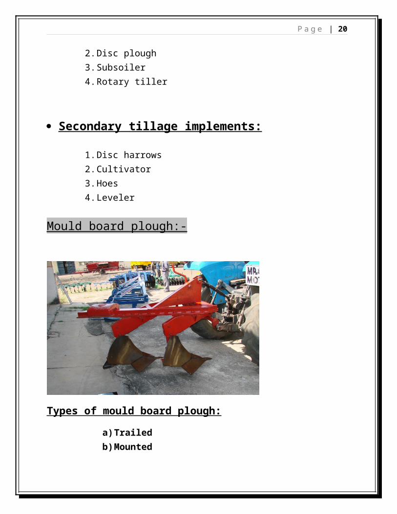
Trailed mould board plough: - This trailed type of plough is also known as pulling type of mould board plough and is complete unit in itself supported on two or three wheels. The complete unit is hitched to the drawbar of a tractor and it trails behind the same. These are available one to five bottoms depending upon the capacity of tractor to pull.Mounted mould board plough: - These types of ploughs are also called tractor mounted ploughs. These ploughs are attached to a tractor at three point linkage and controlled by hydraulic system of the tractor by depth and draft control levers. One way plough: - One ploughs throw the soil in one direction usually to the right when see from behind.Two way plough: - Two way plough has two i.e. , right and left bottoms. The bottoms of two way plough are so arranged that the right turning bottom can be quickly turned with the set which turns the soil to the left thus while ploughing when we have reached the end of the furrow we raise the plough, turn around and return across with two way plough. In this case no back furrow or uneven and shaken spouts are left in the field. Function of mould board plough:-
a) Cutting the furrow sliceb) Lifting the soilc) Turning the furrow sliced) Pulverizing the soil
Components of M.B. plough: -M.B. plough consists of these following parts,
a) Shareb) Mould boardc) Land sided) Frog e) Tail piece
Share: - It penetrates into the soil and makes a horizontal cut below the soil surface. It is sharp, well polished and pointed component. Different portion of share are,
a) Slip shareb) Slip- nose sharec) Shine shared) Bar point share
Mould board plough: - The mould board is that part of the plough which receives the furrow slice from the share and. It lifts, turns and breaks the furrow slice. To suit different soil condition and crop requirements, mould board has been designed in different shapes. These are,
a) General purposeb) Stubblec) Sod or breakerd) Slat
Land side: - It is the flat plate which bears against and transmits lateral thrust of the plough bottom to the furrow wall. It helps to resist the side pressure exerted by the furrow slice on the mould board. It also helps in stabilizing the plough while it is in operation. Land side is fastened to the frog with the help of plough bolts. The rear bottom end of the landside is known as heel which rubs against the furrow sole.Frog: - frog is the part of the plough bottom to which other components of the plough bottom are attached. It is an irregular piece of metal. Tail piece: - It is an important extension of mould board which helps in turning a furrow slice.
P a g e | 18
Plough accessories: -a) Frame and beam b) Cross shaftc) Coulterd) Jointere) Wheels
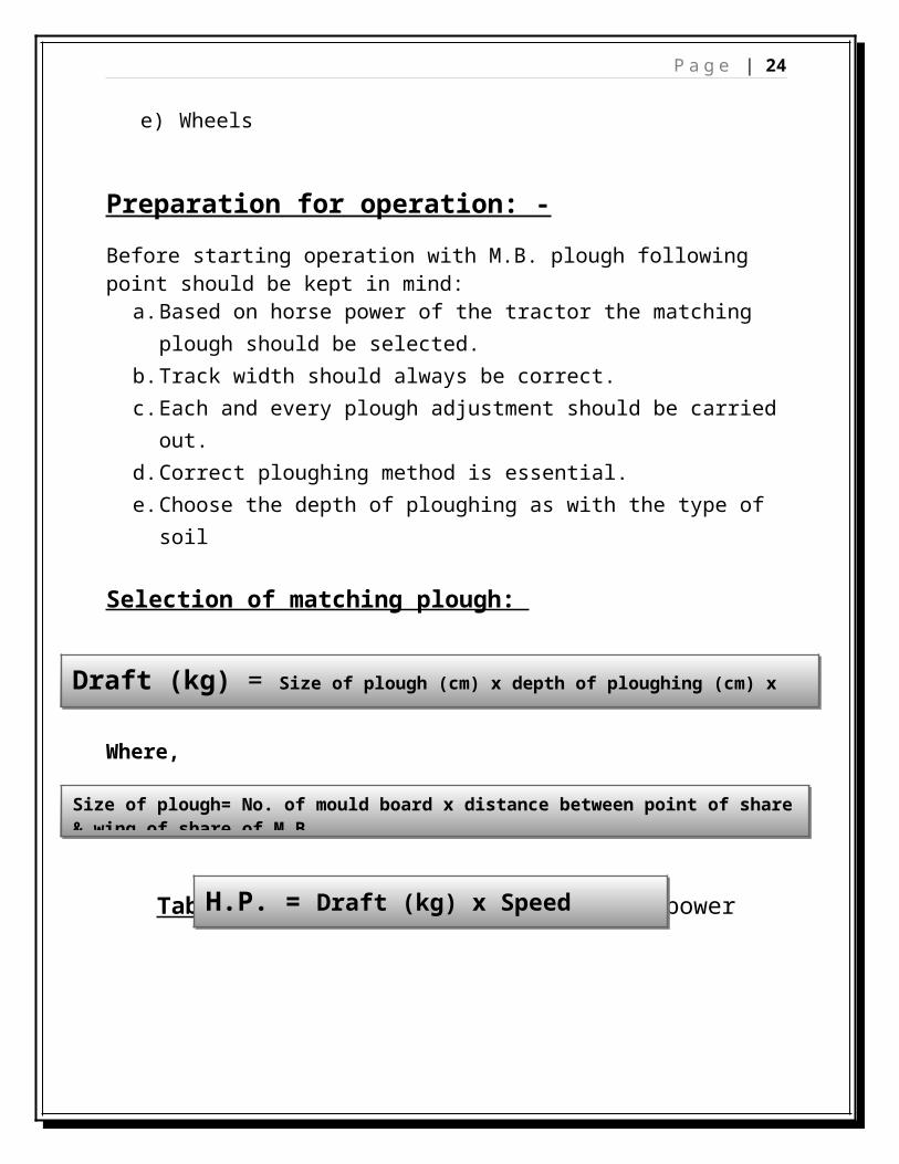
Preparation for operation: -
Before starting operation with M.B. plough following point should be kept in mind:
a. Based on horse power of the tractor the matching plough should be selected.
b. Track width should always be correct.c. Each and every plough adjustment should be carried out.d. Correct ploughing method is essential.e. Choose the depth of ploughing as with the type of soil
Selection of matching plough:
Where,
Table1.Table showing required horse power
Draft (kg) = Size of plough (cm) x depth of ploughing (cm) x soil resistance (kg/cm2)
Size of plough= No. of mould board x distance between point of share & wing of share of M.B.
H.P. = Draft (kg) x Speed (km/hr) / 270
P a g e | 19
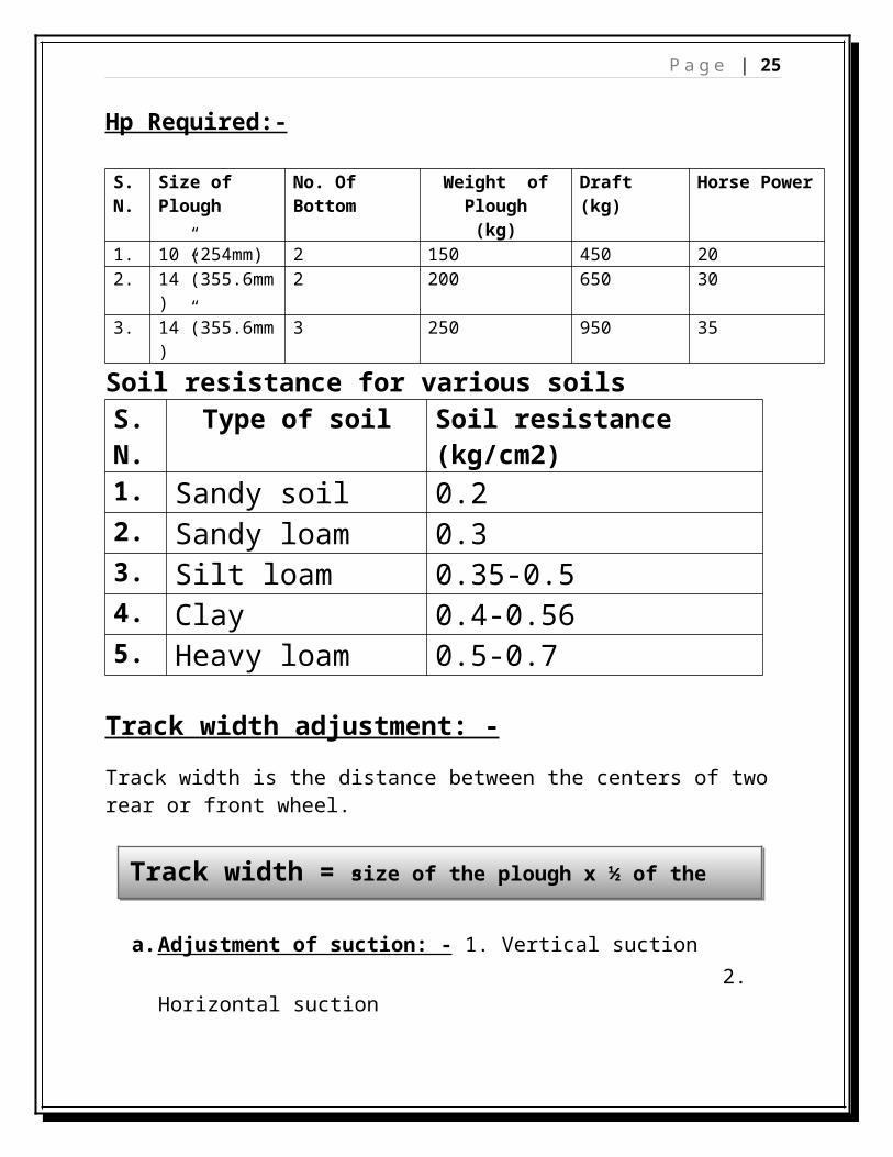
Hp Required:-
Soil resistance for various soilsS.N. Type of soil Soil resistance (kg/cm2)1. Sandy soil 0.22. Sandy loam 0.33. Silt loam 0.35-0.54. Clay 0.4-0.565. Heavy loam 0.5-0.7
Track width adjustment: -
Track width is the distance between the centers of two rear or front wheel.
a. Adjustment of suction: - 1. Vertical suction 2. Horizontal suction
Vertical suction: - This is the bend downward of the point of share to make the plough penetrate the soil to the proper depth when the plough is pulled forward. The amount of suction shall vary from 1/8” to 3/16”.This suction can be measured by placing a straight edge on the bottom of the plough extending from the heel of the bottom of land side to the point of share, then measuring vertically and the greatest clearance from the straight edge to the plough bottom.
Track width = size of the plough x ½ of the single bottom + 3”
S.N. Size of Plough No. Of Bottom Weight of Plough (kg)
Horizontal suction: - Horizontal suction is the amount the point of share is bend off line with the land side. The object of suction is to make the plough take the proper amount of furrow width.Horizontal suction is measured by placing a straight edge on the side of the plough extending from the heel of the landside to the point of share, then measuring horizontally the greatest distance from the straight edge to the plough bottom. The amount is usually about 3/16”.
Plough setting step by step sequence: -a) Cross shaft adjustment.b) Top link setting.c) Lower link setting.d) Coulter.e) Depth of work.f) Tractor and plough alignment.g) Final top link setting.h) Adjusting land side clearance.i) Adjustment of furrow wheel.
Methods of ploughing: - There are following methods of ploughing,1. Gathering 2. Casting3. Mixed method4. Corner to corner
Gathering: - Whenever a plough works round a strip of ploughed land, it is said to be gathering.Casting: - Whenever a plough works round a strip of unploughed land, it is said to be casting. Mixed method: - This is combined method of both “gathering” & “casting” applicable for larger fields. The whole field is divided into number of strips approximately of 20m-30m and 40m for 2, 3, and 4 bottom ploughs respectively. This gives saving in fuel and time.
P a g e | 21
Corner to corner: - This type of ploughing is carried out by reversible plough (two way plough). At the end of each furrow while turning, the mould board is turned to the other side. This provides saving of time by avoiding unnecessary turning.Disc plough: -Disc plough is an implement where the cutting and inversion of soil is performed by means of discs. This was introduced to reduce friction by rolling bottom instead of a bottom that would slide along. Unlike mould board plough, disc plough creates no suction but depends upon weight and disc angle for penetration, therefore they are heavily built. Disc plough must be operated in fairly slow, uniform speed for best cutting action and width of control.
The disc plough usage shows that it is adapted to condition where M.B. plough will not work.
1. It is suitable for dry, hard ground that cannot be penetrated with an M.B. plough.
2. Rough, stony and Rooty ground where the disc will ride over the roots.3. Sticky, waxy ground soil where mould board does not scour.4. It is often used after harvesting grain crops where the ground is hard.
Main parts of disc plough: -1. Concave disc2. Disc bearing3. Disc scraper 4. Standard 5. Frame6. Cross shaft7. Furrow wheel
Concave disc: - It is a circular, concave revolving steel plate used for cutting and inverting the soil. Diameter of disc varies from 60 to 80cm. The concavity of the disc called “dish” varies according to diameter.Disc bearing: - Roller bearings are usually placed in pairs. Taper roller bearing absorbs force in all direction and can readily adjust.Disc scrapper: - It is a device to remove soil that tends to stick to the working surface of disc.Standard: - the standard connects the disc bearing to the plough beam.
P a g e | 22
Cross shaft: - The steel shaft fitted to the plough at the front at right angles to the beam is known as cross shaft.Furrow wheel: - furrow wheel is fixed at the rear end of the plough to the main plough beam. The purpose of furrow wheel is to stabilize the rear of the plough and to hold it in a position to control the width of cut by the front disc.Tractor preparation: -The following are typical instructions for preparing a tractor for operation:
1. The horse power of tractor selected should match the implement.2. Adjust front & rear wheel track width.3. Provide adequate front end ballast for tractor stability.4. Provide proper rear furrow wheel weight.5. All plough adjustments should be carried out.6. Select load and depth control setting according to tractor operation
manual.Adjustments: - In order to get better result, the following adjustments are necessary:
1. Cutting angle adjustment.2. Width of cut adjustment.3. Leveling the plough.4. Tightening bearing.5. Furrow wheel adjustment.
Cutting angle adjustment: -
a) Disc angle adjustment2. Tilt angle adjustment.
Disc angleis the angle which the plain of cutting edge make with the line of travel. It is normally 42-47 degree. Reducing the angle increase disk rotation with respect to ground speed & reduce the tendency of the plough to overcut. Increase the disc angle improves disc penetration.Tilth angle is the angle which the plane of cutting edge makes with the vertical line. It ranges from 15-25 degree. Increasing the tilth angle improves the disc penetration in heavy, sticky soil. Decreasing the tilth angle improves the disc penetration in loose soil.
P a g e | 23
Secondary tillage implements:-
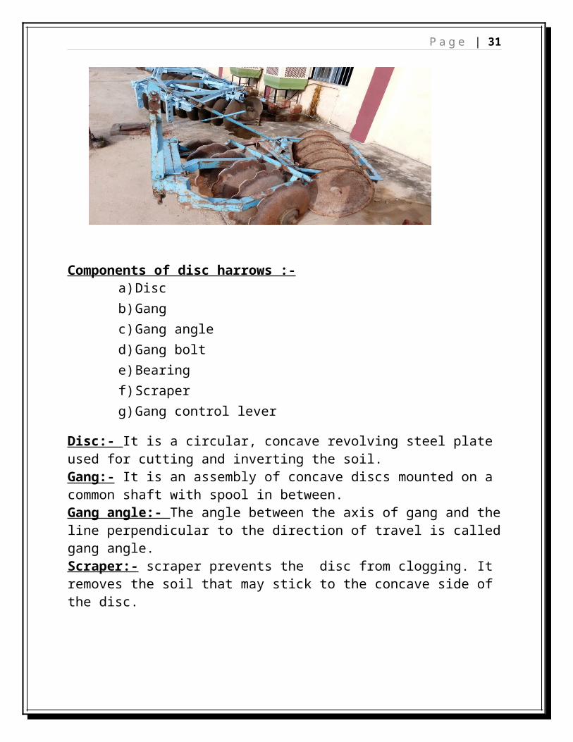
Harrow:-A harrow is an implement that cut the soil to a shallow depth for smoothening and pulverizing the soil as well as to cut the weeds and to mix materials with soil. It is an implement used to breaks the clods after ploughing, to collect trash from the ploughed land and to level the seed bed.Disc harrow:- It is a harrows which performs the harrowing operations by means of a set of rotating steel discs, each set being mounted on a common shaft.
Components of disc harrows :-a) Disc b) Gangc) Gang angle d) Gang bolt e) Bearing f) Scraper g) Gang control lever
Disc:- It is a circular, concave revolving steel plate used for cutting and inverting the soil.
P a g e | 24
Gang:- It is an assembly of concave discs mounted on a common shaft with spool in between.Gang angle:- The angle between the axis of gang and the line perpendicular to the direction of travel is called gang angle.Scraper:- scraper prevents the disc from clogging. It removes the soil that may stick to the concave side of the disc.
Cultivator: - It is an implement for inter cultivation with laterally adjustable tines or discs to work between crop rows. This can be used for seed bed preparation and for sowing with seeding attachment. These tines may have provision for vertical adjustments also.
The cultivator can be:-1. Disc cultivator 2. Rotary cultivator 3. Tine cultivator Disc cultivator: - It is a cultivator fitted with disc.Rotary cultivator: - It is a cultivator with tines or blades mounted on a power driven shaft.Tine cultivator: - It is a cultivator fitted with tines having shovels.
P a g e | 25
The operations performed by a cultivator:- a) Inter culture the fields b) Destroy the weeds in the field.c) Aerate the soil for the proper growth of crops.d) Conserve the moisture by preparing mulch on the surface.e) To sow seeds when it is provided with sowing attachments.f) To prevent surface evaporation and encourage rapid infiltration of rain
water into the soil.
P a g e | 26
IRRIGATION AND PLANT PROTECTION EQUIPMENTS
Trainer:- Sh. D.kumar Date: 15-july-2016
Why need irrigation ?*80 -90% parts make by water.* To seed bed preparing.* To dilute the fertilizer.*To destroy insect and weeds.
SOURCE OF IRRIGATION WATER:Natural water resources (pound, river canal and dam). Ground water resources (Pumps).
Transmission is a speed reducing mechanism, equipped with several gears. It may be called a sequence of gears and shaft, through which engine power is transmitted to the tractor wheels. The system consists of various devices that cause forward and backward moment of tractor to suit different field condition. The complete path of power from the engine to the wheels is called power trains.
Function of power transmission system:-1. To transmit power from the engine to the rear wheels of the tractor2. To make reduced speed available, to rear wheel of tractor3. To alter the ratio of wheel speed and engine speed in order to suit the
field conditions4. To transmit power through right angle drive, because the crankshaft and
rear axial are normally at right angle to each other
P a g e | 33
The Power Transmission System Consists Of:-1. Clutch 2. Transmission gears 3. Differential4. Final drive 5. Rear axial 6. Rear wheels
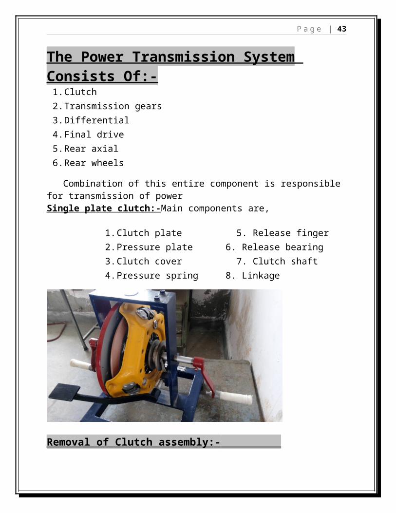
Combination of this entire component is responsible for transmission of power Single plate clutch:-Main components are,
Removal of Clutch assembly:- To remove the clutch, tractor has split in to two parts. Means the engine parts is separated from the transmission.We park the tractor on the leveled ground and kept the wooden blocks on the front side of the front wheel. All physical connection of the tractor will cut between the engine part and the transmission part of the tractor. After the removal of clutch assembly by special tools loosen all bolt connected it with fly wheel Before dismantling the assembly dot marks on the clutch cover, pressure Plate and fingers should be punched so that assembly can be done easily.The next step is to remove pr. Plate, release fingers, pr. Springs etc. Special tools are available which help in the gradual of the unit because the pr. Spring are compressed at very high pr. & any attempt to dismantle without pr. Controlled otherwise the cover will thrown out under spring force . Press gently by clutch dismantling tool and while under pr. The adjusting nuts should be opened .now slowly release the pr. & lift cover remove the release fingers& springs.
Inspection & Repair:-Inspect the clutch disc to make sure that the links are not loose, cracked worn out or oil soaked, the rivets are secure and there is no sign of overheating. The
P a g e | 35
living must be uniform all over engagement will not properly. The hub of clutch plate should be checked for extra wear.
Inspect the surface of the pressure plate & flywheel for grooving, cracking or distortion .if any scratches etc. are of very less depth it should be resurfaced. Generally the pressure plate is resurfaced and not the flywheel as this can effect engine balancing.The clutch shaft should be straight and if there is excessive wear on the splines, it needs replacementAssembly and reinstallation: --Assemble the clutch assembly exactly in the reverse sequence it was dissembled, insuring that the punch marks already made on the fitting at the time of disassembly tally. After assembly a centering tool is used for reinstalling the unit on the flywheel. This makes clutch plate have exactly in line with the pilot bearing. After the reinstalling the unit, the height of fingers are adjusted with the help of adjusting screw. Every clutch assembly has its own adjustment. The tip of all the fingers should equally above the hub of the clutch plate. Sometimes it is measured from some other fix point. Gear Box:-It is the combination of gear wheels by means of which motion is transferred from one shaft to another shaft is called gear train.
Types of gear box: -1. Constant mesh type 2. Sliding mesh type 3. Synchromesh type
P a g e | 36
Constant mesh type: -In the constant mesh transmission the gears are mounted so that they are always in mesh with at least one of the meshing gears free to rotate on the shaft. Splined coupling of various types, usually called shifter collars, are used to engage the gears.Sliding mesh type: - In sliding gear box spur gears are used. The gear ratio is selected by disengaging the traction clutch and sliding the gear on the shaft until it meshes with a mating gear. Synchromesh type: -A synchromesh type has small friction clutches, usually cone type that engages when shift is initiated. The resulting frictional torque is used to prevent engagement of the shifter collar until the rotational speed of the collar and gear are nearly the same, i.e. synchronized. When synchronization occurs, the frictional torque reduces and the shifter collar can then be engaged with the gear to complete the shift. The advantage of synchronized is that gear changes can be made easily without damaging the transmission, even when vehicle is moving.
Components of gear box:-1. Main gear shifting lever 2. Speed range selection lever
Gear box repair: -Basically the gear box transmission system does not require any major repair
unless they have been damaged due to any accident or any poor handling.
Besides damage to gears, worn out or damaged bearing, broken or destroyed
detent springs or some parts which need replacements during the replacement
P a g e | 37
of the part the transmission system should be disconnected from the engine. The
unit has to be further disconnected from the differential housing.
Remove the shift mechanism housing by opening the cover, gear, shift lever, rail
fork, detent balls & spring. The next step is the removal of the main shaft which
will depend upon the method of mounting of bearing on the transmission
housing.
If any baring or cone or any bearing assembles is found to be damaged it
repaired or replaced.
After the entire system has been dismounted and the damaged part replaced it
should be assemble exactly in opposite sequence of the dissemble care should
be taken to adjust the end play of the shaft & pre loading of the baring as per the
manufacturer recommended.
Bearing bushes & all sliding surfaces should be lubricated on the assembly oil;
seals should be lightly greased before assembly.
Differential: -Differential unit is a special arrangement of gears to permit one
of the rear wheels of the tractor to permit to rotate slower or faster than the
other. While turning the tractor on the curved path, the inner wheel has to travel
lesser distance than the outer wheel. The inner wheel requires lesser power than
the outer wheel; this condition is fulfilled by differential unit, which permits one
of the rear wheels of the tractor to move faster than the other at the turning
point. The differential unit consists of:
1. Differential casing
2. Differential pinion
3. Crown wheel
P a g e | 38
4. Half shaft
5. Bevel gear
Fig- Principle of differential
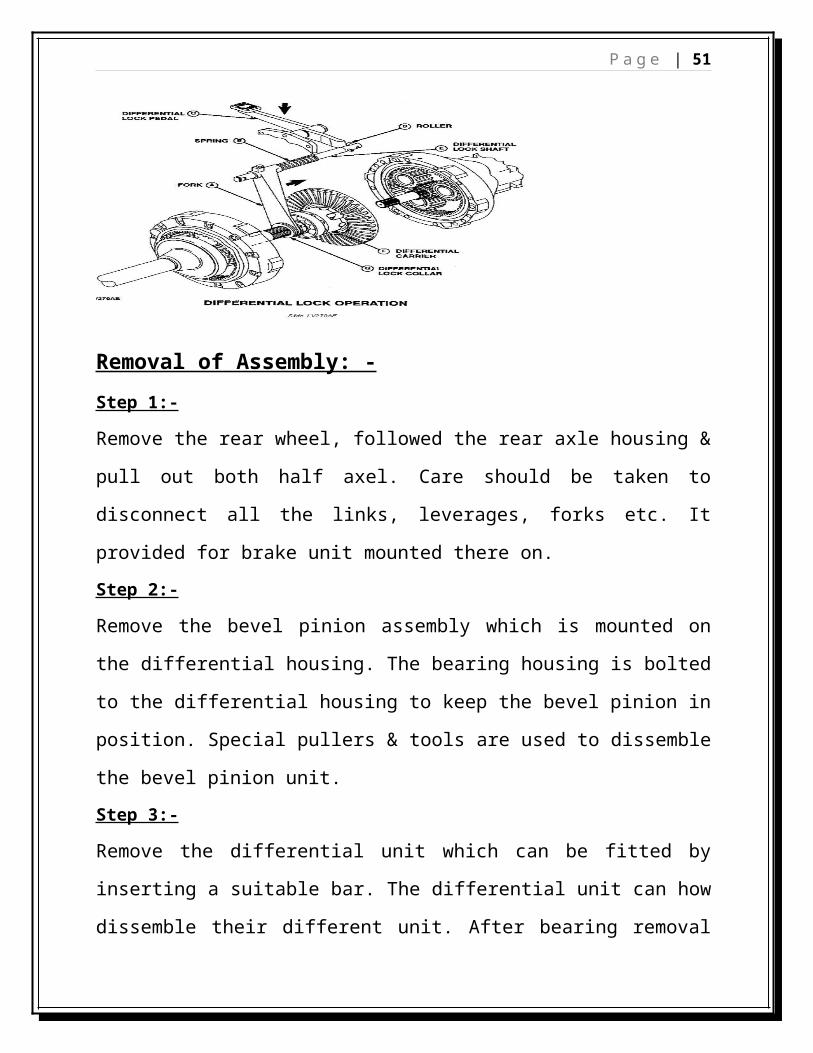
Differential Lock: -Whenever one wheel offers less resistance it turns faster
causing a loss of traction. If one wheel gets in the mud or loose soil, the wheel on the
solid ground will not be driven while the other spins around due to the differential
action. To overcome this problem, all tractors are provided with locking system known
P a g e | 39
as differential lock. The purpose of lock is to join both of axel so that even it one wheel
is under less resistance. The tractor comes out from the mud etc. As the both wheel
moves with the same speed apply equal traction
Removal of Assembly: -
Step 1:-
Remove the rear wheel, followed the rear axle housing & pull out both half axel.
Care should be taken to disconnect all the links, leverages, forks etc. It provided
for brake unit mounted there on.
Step 2:-
Remove the bevel pinion assembly which is mounted on the differential housing.
The bearing housing is bolted to the differential housing to keep the bevel pinion
in position. Special pullers & tools are used to dissemble the bevel pinion unit.
Step 3:-
Remove the differential unit which can be fitted by inserting a suitable bar. The
differential unit can how dissemble their different unit. After bearing removal
remove screw & open the differential cage. Before removing cage bolt the halves
should be marked so that the assembly can be done exactly same relationship.
P a g e | 40
Once the cage is opened the differential pinion gear and cross pins can be taken
out.
Reassembly:-
All disassembled parts are thoroughly cleaned & inspected for, the required
maintained. The assembly procedure is exactly reverse of the disassembly
procedure i.e. first the subassemblies of the differential and bevel pinion are
assembled and then the subassemblies are installed on the differential housing
to complete the differential system.
STEERING AND BRAKE SYSTEMTrainer:- Sh Achinta (Tech. Asst.) Date: 19-july-2016Sh. D.Hasnu (Technition)
STEERING SYSTEM:
Steering system is fitted in the tractor to have effective control throughout its range of speed irrespective of load and road/field condition by steering the machine right or left, without exerting much effort.
Classification of Steering System: -The steering system is classified in following types:- 1)Mechanical steering.2)Power steering.Mechanical steering can be:
1) Single drop arm.2) Double drop arm.
Main Parts of Steering System are:1) Steering Wheel:
P a g e | 41
2) Steering Outer tube3) Steering Shaft4) Steering Drop Arm5) Steering Gear Box6) Tie Rod7) King Pin
Steering Gear Box:The following types of gear boxes were illustrated during the course:
Worm & Sector Type: Worms are cut on steering shaft, this shaft is held in the housing with the help of two bearings, and one at the top and the other at bottom As such it can rotate easily- a sector with identical teeth is held on the sector shaft. On moving the worm, the sector also moves resulting in movement of sector shaft and drop arm.
Worm & Roller Type: In this case a worm is held in the housing with the help of two taper roller bearings. Steering rod is pressed fit in the worm. Sector shaft runs in two bushes, one fitted in the housing and other in the cap and has one U bolt in it. In this U one roller is fixed on the shaft with needle bearing in it and can move freely. This roller is always in contact with teeth of the worm. On moving the worm, this roller also moves resulting in movement of the sector shaft.
Worm & Nut Type: In this case worm and steering shafts are made out of a single piece. This shaft is suspended on self aligned bearing on the upper part of steering tube. This bearing is kept in position with the help of two rubber rings- one placed under the bearing and the other over the bearing and kept tightened with a cap. On moving the worm, the nut also moves up and down, moving the sector shaft along with it.
Worm and Nut with Recirculating Ball Type: Worm is held in the housing with the help of two taper roller bearings. To remove end play, the upper cap has threads made on it. By tightening or loosening this cap the end play is adjusted and the worm should be kept free. After adjustment, it is locked. Nut is screwed on the worm and brought to the centre of worm. 25 steel balls are placed in the nut and 13 steel balls are placed in the U tube. Grease is applied to the balls so that they do not slip while assembling. U tube is fixed on the ball nut. In this way there are 38 steel balls in one circuit. The second circuit is also completed and both tube locked with clamp. After having completed the ball nut, the ball nut is
P a g e | 42
moved on worm to see that there is no end play and nut is moving on worm freely.
Worm and Wheel Type: This type of steering is like worm and sector type, the only difference is that in this case complete gear is fixed on sector shaft whereas in sector type only a sector (of the gear).
POWER STEERING: - In power (hydraulic assisted mechanical) steering, the force required to turn the tractor is very negligible as compared to mechanical steering. In this case the only force required by the operator is to turn the steering wheel which in turn operated the spool valve through which the hydraulic power gives all the steering force. The power steering is fitted in Hindustan 614, MF 245, New Holland, John Deer and Mahindra Arjun tractors. The power steering is sometimes called Hydrostatic steering system. In this steering wheel movements are transmitted to the front wheels by pressurized oil, which helps in easy steering.
Parts of a Hydraulic Steering: -1) Steering wheel 2) HSU(Hydro Static Unit)3) Oil Tank4) Suction Pipe line5) External Gear Pump6) Delivery Pipe Line7) Retainer Pipe with filter8) Hydraulic Cylinder9) Double Acting Piston10) Steering Arm11) Spindle hub
Working of Hydraulic Steering Pump draws the oil from the hydraulic housing through the suction pipe and filter, and supply to the control valve, which directs the oil to the steering cylinder depending on the direction in which the steering wheel is
P a g e | 43
turned. If the steering wheel is not turned, the control valve allows the oil flow back to the hydraulic housing. The steering cylinder is double acting in which piston rod act as piston. The piston rod have the O-ring or oil seals to prevent the leakage of oil pressure steering cylinder is connected to the front axle member with tie rod ends to steering column.
CASTER Caster is the angle to which the steering pivot axis is tilted forward or rearward from vertical, as viewed from the side. If the pivot axis is tilted backward (that is, the top pivot is positioned farther rearward than the bottom pivot), then the caster is negative; if it's tilted forward, then the caster is positive.
CAMBER Camber is the angle of the wheel relative to vertical, as viewed from the front or the rear of the vehicle. If the wheel leans away from the vehicle, it has positive camber. If the wheel leans in towards the chassis, it has negative camber.
P a g e | 44
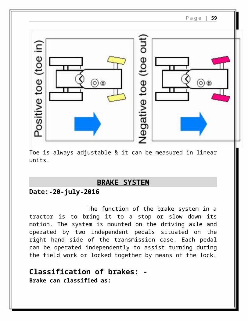
TOE Toe is the symmetric angle that each wheel makes with the longitudinal axis of the vehicle.
Positive toe, or toe in is the front of the wheel pointing in towards the centerline of the vehicle.
Negative toe, or toe out is the front of the wheel pointing in outwards the centerline of the vehicle.
Toe is always adjustable & it can be measured in linear units.
P a g e | 45
BRAKE SYSTEMDate:-20-july-2016
The function of the brake system in a tractor is to bring it to a stop or slow down its motion. The system is mounted on the driving axle and operated by two independent pedals situated on the right hand side of the transmission case. Each pedal can be operated independently to assist turning during the field work or locked together by means of the lock.
Classification of brakes: - Brake can classified as:
DISC TYPE:• A friction pads is pressed against both sides of a rotating disc.• This type of brake is commonly found on the front wheels of
cars.They have good air flow around the brake which quickly dissipates heat.
P a g e | 46
DISC TYPE BRAKE (DRY TYPE)HYDRAULIC BRAKE :It is based on the principle of the pascal’s law. The brake fluid which is usually a mixture of glycerine and alcohol is used .
P a g e | 47
HYDRAULIC SYSTEMTrainer:- Sh. Achinta (Tech. Asst.) Date: 21-july-2016Sh. D. hasnu(technition)
Basics of Hydraulics
1. Liquids do not have the shape of their own. They take the shape of the container.
2. Liquids are incompressible. 3. Liquids transmit applied pressure in all directions.4. Liquids provide great pressure in work force.
Hydraulic Facts:1. Hydraulic power is nearly always generated from mechanical power.2. Hydraulic power generated is used for doing the mechanical works.3. Hydraulic energy is neither created nor destroyed.4. Oil is normally pushed into a pump, not drawn into it. (Atmospheric
pressure provides the push)5. A pump does not create pressure, it creates the flow. Pressure is created
by resistance to flow.
Types of Hydraulic Systems: -There are two types of hydraulic systems namely
Hydrostatics (e.g. A torque converter) Hydrodynamics (e.g. Most hydraulic systems as in a tractor)
Basic Components of a Hydraulic System-a) Reservoir of oil tank g) lift pistonb) Hydraulic Pump h) loadc) Relief Valved) Control Valve
P a g e | 48
e) Control Valve Leverf) Lift Cylinder
Reading of Hydraulic Diagrams
High pressure oil
Medium Pressure oil
Low pressure oil
Pressure free oil
Trapped oil (between any parts of system)
Red light
Little fade red
Fade Red
Blue
Green
P a g e | 49
Direction of flow
Pressure against mechanical object which is restricted
Direction of mechanical movement
Rotation
Load or weight
Types of Hydraulic Pumps
On the basis of Power Driven:
Live Hydraulic Pumps: The pumps which are driven directly by the engine of the tractor are called Live Hydraulic Pump.
Non Live Hydraulic Pump: The pumps which are not driven directly from the engine, instead they are driven from any other system like shaft or gear etc.
On the basis of Design: There are three types of pumps on the basis of design:
Gear type pumps: They are of two types: 1. Internal gear type2. External gear type
Pumpdriven gear
idler gear
P a g e | 50
Vane Pumps: -They are also categorized as
(1). Unbalanced Vane Pumps: They are used in places where low pressure is required for doing work.(2). Balanced Vane Pumps: They are used in places where high pressure is required as in JCBs etc.
Piston Type Pumps: They are categorized asi. Axial Piston Pumps: The pistons are in a direction of axis of
rotation of pumps.ii. Radial Piston Pumps: The pistons are located in a direction
perpendicular to the axis of rotation of pumps.
During the study of pumps, tandem type of pump was dismantled and all its parts were studied along with the working.
P a g e | 51
iii. Inline Axial Piston Pumps: The base on which the piston are mounted is slightly tapered.
Some other types of pumps: Displacement Pumps: They are of two types:
i. Positive Displacement Pumps also called as oil type pumps (High Pressure Low Discharge).
ii. Non Positive Displacement Pumps also called as water type pumps (Low Pressure High Discharge).
The parts of the tendom pump are enlisted below:
1. Retainer Screw 10. Valve chamber assembly2. Front Casting 11. Pump shaft coupling3. Dowel Pin 12. Split pin4. Piston Units 13. Pump drive shaft5. Cam Blocks 14. Relief valve6. Circlip 15. Rear casting7. Valve Chamber Plug 16.valve inlet8. Spring 17.valve outlet.9. C Ring
Types of valves used in Hydraulic SystemsThere are three types of valves used in Hydraulic Systems. They are:
Pressure Control Valves (Used for controlling oil pressure). Direction Control Valves (Used for controlling of direction of oil flow).
They are of three types: Check Valve or Pressure Operated Non Return Valve(NRV) Rotary Valve (Hand or Lever Operated) Spool Valve (Lever operated)
Volume Control Valves (Used for the controlling of volume of oil flow).E.g. Needle Valve Terminologies:
Cracking Pressure: The pressure which is sufficient just to open the valve is called cracking pressure.Full Flow Pressure: The maximum pressure with which the oil flows after opening the valve.Pressure Override Condition: The condition b/w the cracking pressure and full flow pressure Is called the Pressure Override Condition.
P a g e | 52
Type of Ram Cylinders used in Hydraulic Systems:Generally Piston Type Ram Cylinders are used in the hydraulic Systems. There are two types of Piston type Ram Cylinders:
i. Single Acting: Only one side of the piston is pushed by the oil pressure while operating in one direction and the other direction is achieved by the discharge of the oil from the cylinder.
ii. Double Acting: Movement in one direction is achieved by pushing through oil pressure on one side of the piston, and the opposite direction is achieved by pushing through oil pressure on the other side of the piston.
Types of Hydraulic Systems:
There are two types of hydraulic systems used in tractors namely
Open Centre System: The open centre system uses a constant flow pump with an open centre spool valve so that when oil is not flowing to the cylinder, it can pass onto the reservoirs.
P a g e | 53
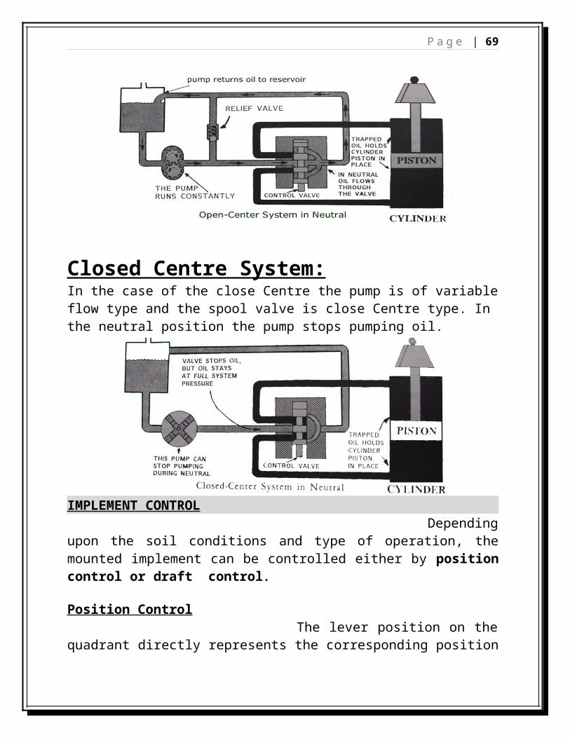
Closed Centre System:In the case of the close Centre the pump is of variable flow type and the spool valve is close Centre type. In the neutral position the pump stops pumping oil.
IMPLEMENT CONTROL Depending upon the soil conditions and type of operation, the mounted implement can be controlled either by position control or draft control.
Position Control The lever position on the quadrant directly represents the corresponding position or depth of the implement. Therefore in position control it is possible to present the working depth. When an implement set for a particular depth in a particular soil enters a heavier soil, the pull resistance increases, which can be observed by slipping of the driving wheels. The result is impaired soil structure and lower output. Therefore normally the position
P a g e | 54
control is used for weeders, planting and sowing machines, sprayers and for transportation of the implement. Draft ControlUnder this system control, the implement is set for a particular draft (drawbar pull) rather than depth. In varied soil conditions the implement automatically takes more or less depth to maintain the predetermined draft. Thus the implement is always running under a specific draft condition which has been once set by the operator as per requirement.
Benefits of ADDC:The benefits of ADDC are as follows:
a) Less fuel consumption.b) Safety for implements.c) Easy drivingd) Long life of engine, gear box and other parts.
Troubleshooting of Hydraulic System
1. Problem: System is not lifting. Causes:
Check oil level Key of pump gear is slipped. Differential valve is jam in open position. Spool is sticky inside the sleeve..
2. Problem : Lift is not lowering Causes:
Mode Selector Valve is closed after lifting. Port No. 3 of sleeve is closed. Hunting in sleeve.
3. Problem:System is heated upCauses:
Over loaded system. Extra pressure is created. Any component is blocked and creating extra pressure.
Note:Hydraulic oil and oil filter must be changed in every 1000 hours
Electrical system of tractor:The main purposes of electrical system of tractor are:
1. To supply current for lighting, starting & horn2. To store the current produced by dynamo/ alternator3. To stabilize the voltage in the electrical system by supplying current to the
electrical accessories when the charging system, is running at low speed
Components of electrical system:1. Battery2. Self starter 3. Dynamo4. Cut-out
1. Construction of battery:
P a g e | 56
It consists of various parts which is mention below Negative plate Positive plate Negative terminal Positive terminal Cell connector Filler cap Cover
The battery is made up of a number of individual cells in hard rubber caseAnd each cell contains positive and negative plates alternatively placed next to each other. These plates hold the active materials in flat grids made of lead and antimony. Charged negative plates contain spongy lead (Pb) which is gray in color. In between positive and negative plates, porous non conducting materials like rubber, synthetic or glass-mates are used as separators which prevent the plates from touching each other. The assembly consisting of positive plate, negative plate & separator is called an element. Each cell has a vent-cap at the top through which liquid electrolyte can be added and also provide a vent for the escape of gasses formed when the battery is charging.
Electrolyte solution:
The electrolyte solution is prepared in the glass container by slowly pouring concentrated (H2SO4 ) sulphuric acid in the water with constant stirring.
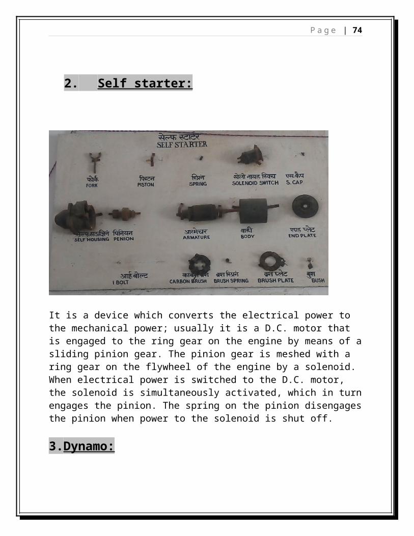
It is a device which converts the electrical power to the mechanical power; usually it is a D.C. motor that is engaged to the ring gear on the engine by means of a sliding pinion gear. The pinion gear is meshed with a ring gear on the flywheel of the engine by a solenoid. When electrical power is switched to the D.C. motor, the solenoid is simultaneously activated, which in turn engages the pinion. The spring on the pinion disengages the pinion when power to the solenoid is shut off.
3.Dynamo:
P a g e | 58
It works on the principle of Faraday’s first law of electro-magnetic induction where electrical power is produced by electro-magnetic induction.
Components of dynamo:The main components of dynamo are as under
Armature assembly Field coils Brushes End shield and body Pole shoes
A rectangular coil of wire is wound on an axis and is kept to rotate easily between the poles of magnet. The rotating coil is called armature. This is wound over thin plates of soft iron to increase the strength of magnetic field. The ends of the coil are in contact with split rings called commutator. Two carbon brushes are in contact with commutator to collect the current produced by the armature.
3. Cut-out: It is a safety device which is used for avoid from the overcharging of battery. Voltage and current regulator is usually called cut-out.It plays a very important part in the charging system of battery. The primary duty of this unit is to keep the voltage and current under control during the charging. At the same time it does not allow the battery current to reverse back to dynamo when the dynamo is running at less speed and producing less current.
Battery used in tractor:
P a g e | 59
Generally 6, 12, 18, 24 volt of battery are used in tractor. The specification of battery is listed in table.
ENGINE: An engine is a machine designed to convert energy into useful mechanical motion. Heat engines, including internal combustion engines and external combustion engines (such as steam engines) burn a fuel to create heat which is then used to create motion.
Classification of heat engines: -
P a g e | 60
Terminologies associated with engine1. Stroke: - It is the length travelled by the piston from BDC to TDC.2. Bore: - It is the diameter of the cylinder liner. 3. Swept Volume: - It is the total volume of the cylinder from TDC to BDC. 4. Clearance Volume: - It is the volume of the cylinder when the piston is at
TDC. 5. Total Volume: - It is the sum of Swept Volume and Clearance Volume. 6. Compression Ratio: - It is the ratio of total volume to the clearance
volume.7. IHP: - The power received by the piston head.8. BHP: - The power obtained by the flywheel.9. DBHP: - The power obtained at the drawbar of the tractor. It is the pulling
power of the tractor. 10.PTOHP: - The power obtained at the PTO shaft of the tractor. 11.Stroke-Bore ratio: - It is the ratio of the stroke length of the piston and
bore Dia of the cylinder.
REQUIREMENT FOR PROPER FUNCTIONING OF ENGINE
RotaryTurbine
P a g e | 61
There are various systems which are essential for the proper functioning of an engine. These systems are enlisted below:-
1. Inlet System: - Inlet system is provided in the tractor to collect the fresh air from the atmosphere, clean it and allow it to enter the combustion chamber. This system has the following parts:
i. Air Cleaner: Air cleaner purifies the air and makes it free from all fine impurities before entering of air into the combustion chamber. Two types of air cleaner namely wet and dry type is used. Dry type air cleaner is cylindrical in shape. Its outer part is made of metal screens and inner part is made of paper screen. The air being cleaned from the air cleaner goes to the inlet manifold. Wet type air cleaner consists of air precleaner which is a primary part to clean the air. From the air precleaner, air moves downward towards the bowl where oil is keep above the bowl, wire mesh is provided. The air enters here from the air pre-cleaner and after being purified goes to the manifold.
ii. Intake manifold:- From the air cleaner chamber, the air moves towards the intake manifold.
iii. Intake valve: - Intake valve is provided on the other side of the intake manifold, which allows the air to pass into the combustion chamber.
2. Exhaust System: - Exhaust system is provided in the tractor to pass out the exhaust gases in the atmosphere. It consists of three parts namely exhaust valve, exhaust manifold and muffler or silencer.
3. Fuel Supply System: - Fuel supply system is provided in tractor to constantly supply fuel in the engine for its functioning during its operation.
4. Lubrication System: - Lubrication system is provided in tractor to serve the following:
i. To reduce the friction between the sliding parts.ii. To reduce the temperature of the parts due to rubbing over
each other.iii. To provide sealing effect for the gases.
5. Cooling system: - Cooling system is provided in the tractor engine for cooling of the engine and maintains the working temperature of the engine for proper it’s functioning. Two types of cooling systems are used namely air cooling and water cooling.The components of water cooling system are
B. Ring spanners:- Double offset type ,bright nicikle plated selected tool steel. It is available 6to 32mm.
C. Sockets:-Chromium vanadium steel .It is available range in 8, 9, 10, 11, 12, 13, 14, 14, 15, 16, 17, 18, 19, 20, 21, 22, 23, 24, 25, 26, 27, 28, 29, 30, 31, 32 (All dim. in mm).
D. Sockets attachment:- Handle 6*1/2&8*1/2
Speed brace
Sliding T-Handle
Reversible ratchet
Ratchet
Square couple
Extension 5”, 3”
P a g e | 64
Universal joint 10”
E. Wrenches:-1. Adjustable wrenches: Selected carbon steel size 6”,8”,10”,12”2. Pipe wrenches: still son pattern selected carbon steel polished size 10”,14”,18”,24”3. Chain pipe wrenches:-Selected steel size 21”long . 4. Tappet wrenches :-Selected carbon steel size: 7/16”&1/2”,1/2”&9/16” 5.Allen key wrenches :-Chrome –Vanadium steel ,non metal finished British size :1/16”,5/64”,3/32”,1/8”,5/32”,3/16”,7/32”,1/4”,5/16”,3/8”
F. Pliers :- 1. Water pump pliers:-Chrome vanadium bright nickel plated size : 255mm,94’10”2. Lock ring pliers:-Chrome vanadium steel ,max. Opening 1*1/8” min. Opening 0.150” length 10*3/16 or 14”3. Break spring pliers:-Chrome vanadium steel 13*1/4 4. Clamp pliers:-8” carbon base 5. Combination slip pliers: - Chrome plated 6”,8”,10” long 6. Size cutting pliers:-5*1/2”,8”,10” long 7. Voice prip pliers:-7”&10”.
G. Hammer:-1.Ballpin hammer: 1/2lb,1lb,1*1/2lb,2lb,3lb.2. Plastic tip hammer: 1/2lb&1lb3. Brass hammer 4. Sludge hammer
H. Some special tools:-
1. Bore gauge 2. Value spring compressor 3. Vernier calipers 4. Micrometers 5.Filler gauge 6.Injector tester
Parts of Single Cylinder engine:
i. Baseii. Crankcase
iii. Flywheel
iv. Crankshaftv. Crank web
vi. Crankpin
P a g e | 65
vii. Crank gear, coverviii. Cam gear
ix. Cam shaftx. Cams
xi. Cam lopexii. Tappets
xiii. Push Rodxiv. Rocker armsxv. Valves (Inlet & Exhaust)
xvi. Gear coverxvii. Decompression lever
xviii. Rocker boxxix. Cylinder headxx. Cylinder liner
xxi. Cylinder blockxxii. Piston
xxiii. Connecting Rodxxiv. Gudgeon pinxxv. Big end & Small end of
connecting rodxxvi. Barrel
xxvii. Plungerxxviii. Fuel tank
xxix. Fuel pipesxxx. Inspection cover
xxxi. Fuel injector pumpxxxii. FI Pump bracket
xxxiii. Nozzlesxxxiv. Oil filterxxxv. Lever pin
xxxvi. Fulcrumxxxvii. Shim
xxxviii. Gasketxxxix. Guide pin (controlled by the
middle cam lope
P a g e | 66
TECHNICAL DETAILS OF 5-HP KIRLOSKER DIESEL ENGINE:-1. Engine type Internal combustion2. Cooling system Water cooled3. Horse power 54. RPM 15005. Bore 80 mm
6. Fuel Used High Speed Diesel
7. Compression Ratio 16.5:1
8. Length of Stroke 116mm
9. Swept Volume 553 cc
10. Capacity of oil sump 2.85 liters
11. Capacity of fuel tank 4.87 liters
12. Capacity of Cooling System by radiator
5.1 liters
13. Fuel Pump Bosh Type
14. Fuel Injection Timing 270 before TDC
15. Fuel Injection Pressure 211 kg/cm2
16. Tappet Clearance a) Inlet valve: 0.20 mmb) Exhaust valve: 0.25 mm
17. Bumping clearance 0.90 to 1.05 mm
18. Maximum ovality of crankshaft
0.075 mm
19. Crankshaft end play 0.12 – 0.30 mm
20. Connecting rod side clearance
0.10 – 0.25 mm
21. Maximum end clearance of piston ring
0.88 mm
22. Lubricating oil consumption 2.75 gm/hp/hr
23. Specific Fuel Consumption 199 gm/hp/hr
24. Valve face margin 0.75 mm
P a g e | 67
Sequence of dismantling of single cylinder engine
Fuel Tank: The fuel (diesel) is filled in this tank which is constantly provided to the engine for its operation. The nuts and bolts of the fuel tank casing were opened with the help of the spanners and the fuel tank was removed along with the hoses.
Rocker Box Cover: - It is also known as the tappet cover. It prevents the entrance of dust, dirt and other foreign materials from entering in the rocker box. It is fitted to rocker box by a screw or nut. It was opened with the help of ring or open end spanner.Rocker Box: - The rocket assembly is located inside the rocker box.Rocker Arm: - They operate the opening and closing of inlet and exhaust valves. The nuts and bolts of the rocker arms were opened and they were removed from the rocker box.
Push Rods: - The push rods are operated by the tappets (cam followers) which are again operated by the cam lope of the camshaft. They were taken out from the rocker box assembly. Decompressor lever: - It is used to break the compression of the engine during starting. Flywheel: The key of the flywheel was removed and the flywheel was detached from the crankshaft. Cylinder Head: - The cylinder head consists of following assembly:-
Breather Fuel Injector Inlet manifold Exhaust manifold Silencer or muffler
P a g e | 68
Removing of Cylinder Head:-
The cooling system was drained; the radiator hose was disconnected & other components which interfere during its removal.
The inlet & exhaust manifold were disconnected & the carbon was removed from the exhaust value opening before the removal of cylinder head.
The injector & spark plug were removed & the holes were cleaned by cotton rag.
The nuts of all valves arrangement were gradually removed by giving half turn at a time in sequence until all of them were quit loose.
The cylinder head was separated from the cylinder block. The gasket was removed. It is advised that the gasket must be changed every time the engine is assembled.
After the removal of cylinder head, the next step was to scrap the traces of carbon which was formed on the walls of combustion chamber & top of the piston. The scraper should be made by soft mild steel.After this the valve assembly was dismantled in sequence.
Complete Valve Assembly:-It consists following parts:-
Valve Valve Spring Spring Retainer Catcher Valve sheet insert
A single cylinder engine has two valves or two ports depending upon their types i.e. whether engine is 4-stroke or 2-stroke.In the Kirloskar AV1 single cylinder engine, one inlet and one exhaust valve isprovided. The parts of a valve are:
P a g e | 69
Valve tip Lock groove Stem Neck Face Margin Valve Head
Tappet Clearance: The clearance between the valve tip and rocker arm is called the tappet clearance. It is about 0.20 mm for inlet valve and about 0.25 mm for the exhaust valve.
Removing valves & Accessories:- The valves should be marked so that they can be replaced in their original position. Generally the size of head of exhaust valve is slightly greater than the inlet valve. For removing the valve assembly, valve spring was compressed with the fixture level & the spring locks were removed. The tools were released & the valve spring, retainers & valves were removed. When the values have been removed, the carbon deposit on the valves was cleaned.
Main parts of 5HP Water Cooled Diesel Engine:-
(A)Rocker Arm Box1. Decompression lever2. Rocker Arm3. Rocker Arm Assembly4. Valve adjusting screw5. Push rod6. Mounting hole
(B) Cylinder headi. Cylinder head
ii. Inlet valveiii. Exhaust valveiv. Exhaust manifold &
Silencer
v. Inlet manifold & air cleaner
vi. Injectorvii. Water outlet
viii. Nozzle tipix. Breather tube
P a g e | 70
x. Valve seatxi. Margin
xii. Neckxiii. Stampxiv. Locking groove
xv. Tipxvi. Valve returning spring
xvii. Valve returning seatxviii. Catcher
(C) Cylinder block(1) Head gasket(2) Liner or Cylinder (wet
type)(3) Bracket of fuel tank(4) Inlet pipe for fresh
water(5) Piston(6) Combustion chamber(7) Piston ring
(30) High pressure pipe which one end connected to the fuel injection pump and other end connected to the injector.
After removing of cylinder head, the fuel injection pump was removed and dismantled.
The parts of the FIP are:-
Delivery valve holder Delivery valve spring Delivery valve Delivery valve seat Pump Element
(Plunger & Barrel) Pump body Control rod or rack Control Sleeve Spring retainer Plunger spring C-lock Plunger guide Dust cover Lock spring Cover screw
P a g e | 72
Arrangement of FIP: On the inlet side, the plunger is fitted inside the barrel which is adjusted inside the pump body. Below the plunger, plunger spring is adjusted. On the bottom of the plunger, the spring is locked by a C-lock. Above this, the assembly is covered by a plunger guide. On the side of the pump body, the control rod or rack is provided which is adjusted with the control sleeve through rack and pinion arrangement. The control sleeve is provided in the outlet side of the injector pump body,. Below the control sleeve delivery valve seat is provided. On this the valve is adjusted followed by the valve spring. This assembly is covered and adjusted by the delivery valve holder.
The parts of a fuel injector are : Injector cap Spring holder Adjusting screw with lock nut Spindle spring Spindle Injector body Nozzle holder Nozzle Needle valve
The fuel supply pump forces fuel under low pressure (2 kg/cm2 approx.) through the fuel filters to the injection pump, which is generally driven by the camshaft. Its function is to deliver a metered quantity of fuel at a predetermined time under pressure (211 kg/cm2) through the tubing to the injection nozzles. These pumps are mostly constant stroke (jerk) type. The pump is an assembly of closely fitted accurately machined and polished plunger and barrel. The plunger has a helical cut in it and is retained in it. When the plunger is pumped, the fuel is injected through the helical cut in the plunger, and through barrel it is pumped out. The control of fuel is done by the control rack and control sleeve. If the spring in the injector gets loose, the injector tester is used to repair the spring and the injection pressure of 211 kg/cm2 is maintained.
P a g e | 73
Removing the piston and crankcase assembly1) First of all the gear cover was taken out. Then the crank gear and the cam
gear were taken out by removing their locking keys.
2) After this, the piston was removed from the crankshaft. The nuts and bolts were removed from the big end of the connecting rod. The piston was taken out of the crankcase.
3) The thrust of the piston is balanced by the balancing weight of ballasting weight. They were also removed from their positions.
4) The tappets were removed from their position.
5) Then, the crankshaft and the camshaft were removed from their position.
6) The oil in the sump was drained and was collected in a container. The crankcase was cleaned and was inspected for the traces of impurities present in the oil. All the fine particles were cleaned from the crankcase and oil sump.
P a g e | 74
Lubrication System:-Generally SAE 90 is preferred for the lubrication system of an engine but multiple grade oils can also be used.
The flow chart of lubrication system is illustrated below:
At the last day of our training , we were collected in a assembly for getting of our certificates of 25 days of training at NERFMTTI,Bishwanath chariali(Assam) . The Director K.K.Nagle, distributed the certificates to the individual students, and he motivated the trainees to contribute their knowledge for the development of the country.