Important Safety InstructionsRead all warnings and instructions in this manual. Save these instructions.
Model 224701 shown (does not include drum or Filter-Regulator-Lubricator Kit)
Warnings
2 308154G
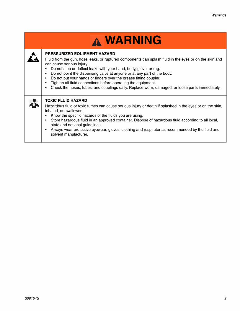
WarningsThe following warnings are for the setup, use, grounding, maintenance, and repair of this equipment. The exclama-tion point symbol alerts you to a general warning and the hazard symbols refer to procedure-specific risks. When these symbols appear in the body of this manual, refer back to these Warnings. Product-specific hazard symbols and warnings not covered in this section may appear throughout the body of this manual where applicable.
WARNINGEQUIPMENT MISUSE HAZARD Misuse can cause death or serious injury.• Do not operate the unit when fatigued or under the influence of drugs or alcohol.• Do not exceed the maximum working pressure or temperature rating of the lowest rated system com-
ponent. See Technical Data in all equipment manuals.• Use fluids and solvents that are compatible with equipment wetted parts. See Technical Data in all
equipment manuals. Read fluid and solvent manufacturer’s warnings. For complete information about your material, request MSDS from distributor or retailer.
• Do not leave the work area while equipment is energized or under pressure. • Turn off all equipment and follow the Pressure Relief Procedure when equipment is not in use.• Check equipment daily. Repair or replace worn or damaged parts immediately with genuine manu-
facturer’s replacement parts only.• Do not alter or modify equipment. Alterations or modifications may void agency approvals and create
safety hazards.• Make sure all equipment is rated and approved for the environment in which you are using it.• Use equipment only for its intended purpose. Call your distributor for information.• Route hoses and cables away from traffic areas, sharp edges, moving parts, and hot surfaces.• Do not kink or over bend hoses or use hoses to pull equipment.• Keep children and animals away from work area.• Comply with all applicable safety regulations.
FIRE AND EXPLOSION HAZARD When flammable fluids are present in the work area, such as gasoline and windshield wiper fluid, be aware that flammable fumes can ignite or explode. To help prevent fire and explosion:• Use equipment only in well ventilated area.• Eliminate all ignition sources, such as cigarettes and portable electric lamps. • Keep work area free of debris, including rags and spilled or open containers of solvent and gasoline.• Do not plug or unplug power cords or turn lights on or off when flammable fumes are present.• Ground all equipment in the work area.• Use only grounded hoses.• Stop operation immediately if static sparking occurs or you feel a shock. Do not use equipment
until you identify and correct the problem.• Keep a working fire extinguisher in the work area.
Warnings
308154G 3
PRESSURIZED EQUIPMENT HAZARDFluid from the gun, hose leaks, or ruptured components can splash fluid in the eyes or on the skin and can cause serious injury.• Do not stop or deflect leaks with your hand, body, glove, or rag.• Do not point the dispensing valve at anyone or at any part of the body.• Do not put your hands or fingers over the grease fitting coupler.• Tighten all fluid connections before operating the equipment.• Check the hoses, tubes, and couplings daily. Replace worn, damaged, or loose parts immediately.
TOXIC FLUID HAZARDHazardous fluid or toxic fumes can cause serious injury or death if splashed in the eyes or on the skin, inhaled, or swallowed.• Know the specific hazards of the fluids you are using.• Store hazardous fluid in an approved container. Dispose of hazardous fluid according to all local,
state and national guidelines.• Always wear protective eyewear, gloves, clothing and respirator as recommended by the fluid and
solvent manufacturer.
WARNING
Installation
4 308154G
Installation
Grounding
1. Pump: Connect a ground wire (A) to the pump. Con-nect to the other end to a true earth ground. Order Grounding Kit (Part No. 222084). (FIG. 1)
2. Air Compressor: Follow the manufacturer’s recom-mendations.
3. Use only metal or conductive containers.
4. All solvent pails used when flushing, according to local code. Use only metal pails, which are conduc-tive. Do not place the pail on a non-conductive sur-face, such as paper or cardboard, which interrupts the grounding continuity.
FIG. 1
A
Installation
308154G 5
Typical Installation1. Install the wheels on the dolly, or assemble the truck
according to the instructions supplied with it.
2. Put the drum on the dolly or truck. The truck has a chain and clip (A) to secure the drum.
3. Position the pump between the bung hole and vent hole of the drum. (FIG. 2 and FIG. 3)
4. Loosen the top screw (14) of each pump clamp (18) and reposition the clamps as needed to fit the rim of the drum.
5. Tighten the screws (17) to secure the pump to the rim of the drum.
6. Install the wand storage tube (supplied). Place the holder (206) on the lip of the dolly or truck.
7. Place the tube (202) in the holder and slide the bracket (203) over the tube.
8. Align the bracket (203) to the holder (206) and secure the bracket to the rim of the drum.
9. Remove the drum’s vent hole cover and install the vented fluid gauge (23).
10. Remove the drum’s bung hole cover and install the plug (24).
11. Put the 50” drain hose (1) into the drum through the bung hole.
12. Connect a wand (104) to the quick coupler (7). Store the wand in the storage tube (202) until needed.
FIG. 2: 55 Gallon Unit
A
103
206
202
18
101
7104
23
202
203
204/205
1
24
Installation
6 308154G
Air Regulation
If you are using the optional air line Filter-Regula-tor-Lubricator (Kit 110149), see page 6 for installation instruction.
If you are providing your own regulation, you should install a quick disconnect coupler at the air hose and pump inlet or regulator.
Optional Fluid Filter for Evacuation Mode
When evacuating particle-contaminated lubricants from the 16 or 55 gallon drum to another container use a suc-tion hose with filter (kit 223888) to prevent damage to the pump.
FIG. 3
16 gallon drum not included
101
105
206
202
24
204/205
1
203
202
23
7
104
Installation
308154G 7
Adding an Optional Air Line Filer-Regulator-Lubricator (FRL) Kit
Proper conditioning of compressed air help prolong the life of your pump. In the FRL Kit, the filter removes harmful dirt and moisture from the compressed air, the regulator controls air to the pump and the lubricator pro-vides automatic motor lubrication.
Graco FRL (Part No. 110149) should be mounted to the Fas-Vac with the Mounting Kit (Part No. 224759).
1. Remove the two manifold screws, flat washers, and lockwashers (A) from the pump.
2. Install the accessory bracket (B) so that its large hole faces up.
3. Install the screws and lockwashers (do not use the flat washers).
4. Remove the male quick disconnect fitting (20) from the pump and install it in the air filter inlet (J).
5. Hold the FRL with the air filter (H) to the left. Install the gauge (C) in the back port of the regulator (not the top) and turn it so the gauge faces up.
6. Install the plug (G) in the front port of the gauge.
7. Remove the lock ring (F) from the base of the air regulator knob.
8. Angle the FRL into the bracket so the gauge slides into the slot in the bracket.
9. Screw the lock ring (F) over the regulator knob to secure the assembly to the bracket.
10. Install a 90° nylon connector (E) to the FRL outlet on the side of the lubricator.
11. Install the other connector to the pump air restricter inlet (not visible in FIG. 4).
12. Tighten the connectors in a position that allows easy installation of the nylon tube (D). Install tube.
FIG. 4
20
A
BC D
E
F
G
J
H
Operation
8 308154G
Operation
Control Knob
The Fas-Vac system operates in two modes: evacuate lubricants from the crankcase or reservoir and collect the material in a 16 gallon or 55 gallon drum, and drain the stored lubricants from the drum to a larger container. The modes are selected with a lock-in-place control knob (A). See FIG. 5.
When the system is not in use, lock the knob in the evacuation mode.
Suction Wands
Experiment to determine which wand is best for your application. Typically, use the largest wand possible. A quick-disconnect coupler make it fast and easy to switch wands.
Fluid Gauge
The fluid gauge (23) indicates approximately how full the drum is to avoid over-filling it (FIG. 5). When it’s red cap is even with the top, the drum will be 75% to 80% full.
Evacuation
1. Check the gauge level.
2. Be sure that the control knob (A) is in the EVACUA-TION position and the safety clip (8) locks it in place.
3. Connect the air supply hose to the pump air inlet (B). Operate the pump at 40-50 psi (2.72- 3.4 bar, 0.27-0.34 MPa) for the best results.
4. Insert the suction wand (104) in the crankcase or reservoir.
5. Disconnect the air to the pump when the evacuation in complete.
Draining the Drum
1. Remove the suction wand (104).
2. Attach the suction hose quick-disconnect coupler to the male coupler fitting of a waste oil tank, or dis-charge the material to an access opening.
3. Pull out the safety clip (8) and turn the control knob (A) to drain drum.
4. Connect the air supply hose to the pump.
5. When the draining is complete, disconnect the air to the pump, turn the valve knob (A) back to the evacu-ation position and install the safety clip (8).
FIG. 5
10423
8
A
B(when using FRL kit)
Parts
308154G 9
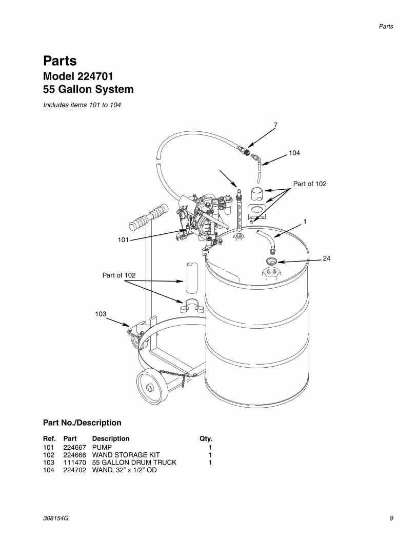
PartsModel 22470155 Gallon SystemIncludes items 101 to 104
Part No./Description
Part of 102
7
104
1
24
103
Part of 102
101
Ref. Part Description Qty.101 224667 PUMP 1102 224666 WAND STORAGE KIT 1103 111470 55 GALLON DRUM TRUCK 1104 224702 WAND, 32” x 1/2” OD
Parts
10 308154G
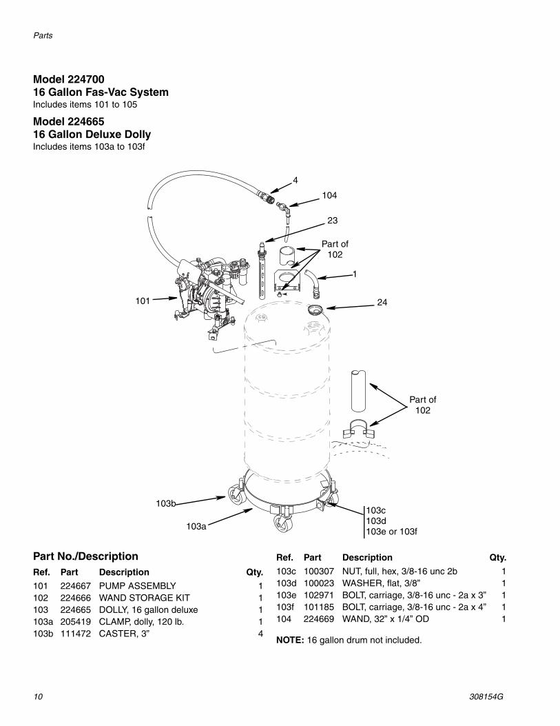
Model 224700 16 Gallon Fas-Vac System Includes items 101 to 105
Model 22466516 Gallon Deluxe DollyIncludes items 103a to 103f
18 187354 BRACKET, mounting 219❄ 241906 HUSKY 716 PUMP 120 169970 FITTING, air line 121 111474 HOSE, cpld 1/2-14 npt x 3/4-14 npt,
20” (0,5 m) long1
22 103473 STRAP, wire tie (not shown) 123 111467 GAUGE, drum fill 124 183553 PLUG, bung 125 187359 4-WAY VALVE 1❄See manual 308573 for parts
Ref. Part Description Qty.
Technical Data
12 308154G
Model 224666Wand Storage Kit
Part No./Description
Suction Wands with 32” TubeIncludes items 301 to 303Model 224669 is included with 16 gallon systemsModel 224702 is included with 55 gallon systems
Technical DataMaximum Air and Fluid Working Pressure..............................................................................50psi (3.5 bar, 0.35 MPa)System Wetted Parts........................................................................................PVC, High Density Polyethylene, Brass,
All written and visual data contained in this document reflects the latest product information available at the time of publication. Graco reserves the right to make changes at any time without notice.
For patent information, see www.graco.com/patents.
Original instructions. This manual contains English. MM 308154
Graco Headquarters: MinneapolisInternational Offices: Belgium, China, Japan, Korea
GRACO INC. AND SUBSIDIARIES • P.O. BOX 1441 • MINNEAPOLIS MN 55440-1441 • USA
Copyright 1991, Graco Inc. All Graco manufacturing locations are registered to ISO 9001.www.graco.com
Revised September 2012
Graco Standard WarrantyGraco warrants all equipment referenced in this document which is manufactured by Graco and bearing its name to be free from defects in material and workmanship on the date of sale to the original purchaser for use. With the exception of any special, extended, or limited warranty published by Graco, Graco will, for a period of twelve months from the date of sale, repair or replace any part of the equipment determined by Graco to be defective. This warranty applies only when the equipment is installed, operated and maintained in accordance with Graco’s written recommendations.
This warranty does not cover, and Graco shall not be liable for general wear and tear, or any malfunction, damage or wear caused by faulty installation, misapplication, abrasion, corrosion, inadequate or improper maintenance, negligence, accident, tampering, or substitution of non-Graco component parts. Nor shall Graco be liable for malfunction, damage or wear caused by the incompatibility of Graco equipment with structures, accessories, equipment or materials not supplied by Graco, or the improper design, manufacture, installation, operation or maintenance of structures, accessories, equipment or materials not supplied by Graco.
This warranty is conditioned upon the prepaid return of the equipment claimed to be defective to an authorized Graco distributor for verification of the claimed defect. If the claimed defect is verified, Graco will repair or replace free of charge any defective parts. The equipment will be returned to the original purchaser transportation prepaid. If inspection of the equipment does not disclose any defect in material or workmanship, repairs will be made at a reasonable charge, which charges may include the costs of parts, labor, and transportation.
THIS WARRANTY IS EXCLUSIVE, AND IS IN LIEU OF ANY OTHER WARRANTIES, EXPRESS OR IMPLIED, INCLUDING BUT NOT LIMITED TO WARRANTY OF MERCHANTABILITY OR WARRANTY OF FITNESS FOR A PARTICULAR PURPOSE.
Graco’s sole obligation and buyer’s sole remedy for any breach of warranty shall be as set forth above. The buyer agrees that no other remedy (including, but not limited to, incidental or consequential damages for lost profits, lost sales, injury to person or property, or any other incidental or consequential loss) shall be available. Any action for breach of warranty must be brought within two (2) years of the date of sale.
GRACO MAKES NO WARRANTY, AND DISCLAIMS ALL IMPLIED WARRANTIES OF MERCHANTABILITY AND FITNESS FOR A PARTICULAR PURPOSE, IN CONNECTION WITH ACCESSORIES, EQUIPMENT, MATERIALS OR COMPONENTS SOLD BUT NOT MANUFACTURED BY GRACO. These items sold, but not manufactured by Graco (such as electric motors, switches, hose, etc.), are subject to the warranty, if any, of their manufacturer. Graco will provide purchaser with reasonable assistance in making any claim for breach of these warranties.
In no event will Graco be liable for indirect, incidental, special or consequential damages resulting from Graco supplying equipment hereunder, or the furnishing, performance, or use of any products or other goods sold hereto, whether due to a breach of contract, breach of warranty, the negligence of Graco, or otherwise.
FOR GRACO CANADA CUSTOMERSThe Parties acknowledge that they have required that the present document, as well as all documents, notices and legal proceedings entered into, given or instituted pursuant hereto or relating directly or indirectly hereto, be drawn up in English. Les parties reconnaissent avoir convenu que la rédaction du présente document sera en Anglais, ainsi que tous documents, avis et procédures judiciaires exécutés, donnés ou intentés, à la suite de ou en rapport, directement ou indirectement, avec les procédures concernées.
Graco InformationFor the latest information about Graco products, visit www.graco.com.
TO PLACE AN ORDER, contact your Graco distributor or call to identify the nearest distributor.Phone: 612-623-6928 or Toll Free: 1-800-533-9655, Fax: 612-378-3590


![1 Pensions (FAS 87); Post Retirement Benefits (FAS 106); Post Employment Benefits (FAS 112); Disclosure about Pensions, etc. (FAS 132 [R]) – amendment.](https://static.documents.pub/doc/80x56/56649d1f5503460f949f3b1c/1-pensions-fas-87-post-retirement-benefits-fas-106-post-employment-benefits.jpg)


