22
APPLICATION: T 095G (95GPH @ 16-18psi) T 150G (150GPH @ 16-18psi) CLASS 1-CLASS 8 *Requires a Fuel Line Kit* INSTALLATION MANUAL

APPLICATION:T 095G (95GPH @ 16-18psi)
T 150G (150GPH @ 16-18psi)
CLASS 1-CLASS 8*Requires a Fuel Line Kit*
INSTALLATION MANUAL

FASS Recommended Application
T 095G Class 1– Class 7, Agriculture, Industrial, Recreational, Hwy and off-road.
Applications requiring fuel flow demands of 16-18psi and less than 95gph
T 150G Class 1– Class 8, Agriculture, Industrial, Recreational, Hwy and off-road.
Applications requiring fuel flow demands of 16-18psi and less than 150gph
¡WARNINGs! WARNING: Do not tie FASS Return in
with engine return. Back pressure can
cause damage to engine.
Read all instructions before starting installation of this product!
Installing the improper FASS Pump can cause severe engine damage. This unit was not de-
signed to be used on Unit Injected Mechanical Engines. Refer to the FASS kits with UIME
in the model number.
Do Not Remove any factory installed secondary fuel filter! Removal of a factory installed
secondary fuel filter may void the engine manufacturer’s warranty. This is the fuel filter
between the engines fuel pump and the injectors.
Be sure that the serial # on this installation manual matches that of the outside of the box.
Keep debris from entering the internals of the system during installation. Getting debris in
the water separator nipple can lock up the motor. If the motor does lock up from debris call
FASS for technical assistance.
Properly secure lines to prevent chaffing.
Use caution when drilling. Steer clear of any electrical wires , air lines or other damageable
components.

INSTALLATION MANUAL
Follow these steps to ensure a simple installation of your new
FASS TITANIUM FUEL SYSTEM
1. Read the installation manual completely before attempting installation. The instal-
lation of this product indicates that the buyer has read and understands the limita-
tions of the FASS manufacturers warranty agreement and accepts the responsibility
of its terms and conditions.
2. Inventory the package components. Notify the place of purchase immediately of
any parts missing or damaged.
3. The installation recommendations contained herein are guidelines. Use good judg-
ment and take into consideration your vehicles' accessories.
4. For best results in accuracy and efficiency (due to training, communication, and our
relationship with our dealer network), we recommend a ViP FASS dealer for the
installation. They are prepared to install the FASS fuel pumps with the most effi-
ciency. If a situation/problem arises during the installation, they are the most pre-
pared for that situation/problem. DPPI is not responsible for any installation mis-
takes.

Titanium Series
95 or 150 GPH
16-18 PSI (Approximately)
‘R’
Fuel Return to Tank
“E”
To Engine
Serial Number Location
‘G’
Fuel Pressure
‘T’
Fuel Inlet
Electric Heater
Port
“H”
Coolant Heater
2nd
Electric Heater Port
Installation
Step 1: Install Electrical Harness
Step 2: Prepare Suction and Return Lines
Step 3: Mount Fuel System
Step 4: Install Fuel Line
Step 5: Check Installation
A fuel pressure gauge is highly recommended to identify fuel filter life and to prevent engine damage!

Contents
WH-1001
BR-2001
MP-9026

Mounting Package Contents
Mounting template
RS-1001 RS-2684
Spade Terminal
10-273
4 Locking Nut 3/8”
3 WA-1001D
4 3/8-16”x 1 1/2” Hex Bolt
3 Hex Bolt 1/4-20 13/4"

Step 1: Installing Electrical Harness
A. Select best location in firewall for passage of wiring harness from cab to engine compartment.
B. Find or drill a 7/8” hole in firewall. Install RS-2684 grommet for ease of installation and protection of
wire harness.
C. Route red wire/ loom of the wire extension through the grommet in the firewall to the ignition or fuse
panel. Use of corrosion preventative spray and dielectric grease is recommended where electrical con-
nection are made..
D. Connect the “Red” lead to the “ON” terminal of the ignition switch or a terminal on the circuit break-
er board that is “hot” when the key is on. Use a test probe to locate the “hot side” of the circuit in
the fuse block.
E. Using the ring terminals, connect the green wire of the wire harness to the negative post.
Note: When connecting ground make sure connection is on a clean and not painted surface, ie Engine,
Frame, or Battery.
F. Properly secure all electrical leads and harness.
The installation of the electrical harness is done first, allowing power to be applied to the pump for
lubrication purposes.

NOTE
ATTENTION: While installing fittings into Titanium pump
DO NOT Apply side pressure to draw
tube of pump
Improper
Proper

Step 2: Mounting the FASS
A. Remove primary fuel and/or water separator. If primary filter is part of the fuel pump, ignore this step.
Some of the photo’s are of a different application, procedures are the same.
NOTE: Before installing fittings make sure to inspect for burs or flare imperfections.
When cutting fuel line make sure to blow out line to keep debris from moving forward.
B. Using thread tape, install the fittings into the “E” and the “T” ports (on opposite end). Torque to 40 lb./
ft.² Note: Do Not Put Thread Tape on Flare of Fitting ***The use of thread sealant
is not recommended***
C. Attach BR-2001 to back of system using the spacers and 1/4” bolts. Use the two bottom bolts and the
very top one bolt opening.
Step 2: Mounting the FASSSome of the photo’s are of a different application, procedures are the same.
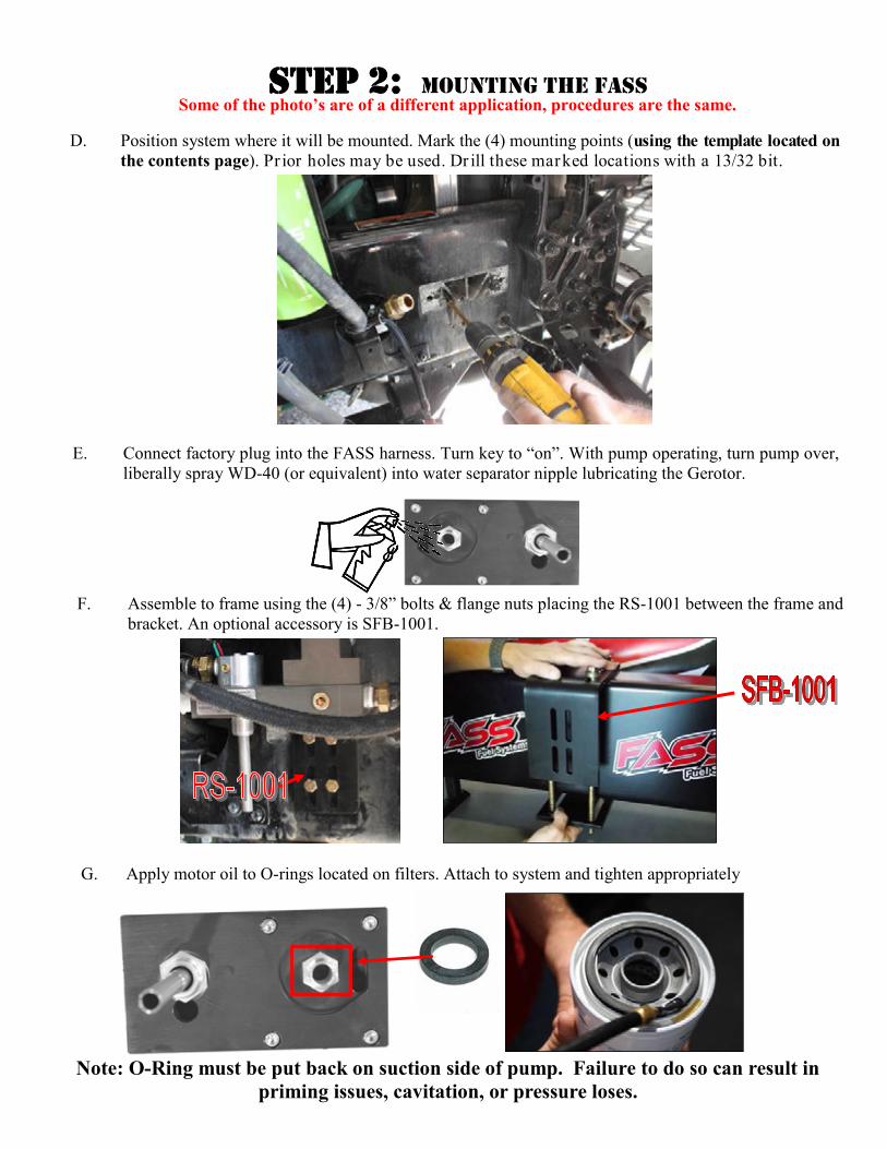
D. Position system where it will be mounted. Mark the (4) mounting points (using the template located on
the contents page). Pr ior holes may be used. Dr ill these marked locations with a 13/32 bit.
G. Apply motor oil to O-rings located on filters. Attach to system and tighten appropriately
E. Connect factory plug into the FASS harness. Turn key to “on”. With pump operating, turn pump over,
liberally spray WD-40 (or equivalent) into water separator nipple lubricating the Gerotor.
F. Assemble to frame using the (4) - 3/8” bolts & flange nuts placing the RS-1001 between the frame and
bracket. An optional accessory is SFB-1001.
Note: O-Ring must be put back on suction side of pump. Failure to do so can result in
priming issues, cavitation, or pressure loses.

Step 3: Identify Fuel Line Configuration
A. Fuel lines, excluding nylon type fuel lines, in excess of 6 years old should be replaced due to interior
lining deterioration. This condition can cause many problems including but not limited to: fuel starva-
tion, uneven fuel tank levels and etc.
B. When routing the return line from the FASS Fuel System, you will need to first identify your current
fuel system. Now match with the correct fuel line section below and follow the corresponding proce-
dures. Uneven fuel level conditions can occur between the tanks if the pickup/return lines are improp-
erly installed.
B1. Most Popular - Usually on 1994 Trucks & Newer including Volvo and Mercedes Engines:
Double Draw/Double Return Line System. FASS fuel line kit (FLK-S03) or Double Vent Return
Line Kit for trucks without the extra port of the fuel tanks(FLK-SO6)should have all of the product to
complete this process
B2. 2nd Most Popular - Usually on 1993 Trucks & Older (except 359 Peterbilt - next selection):
Single Draw/Single Return Line System. FASS fuel line kit (FLK-S02) should have all of the product
to complete this process
B3. 359 Peterbilt: Single Draw Out of Cross Over Fuel Line/Single Return Line System
Dual Tank Recommendation:
1st Choice - Conver t to a complete Double Draw/Double Return Line System(FLK-S03) or Dou-
ble Vent Return Line Kit (FLK-S06).
2nd Choice - Conver t to a true Single Draw/Single Return Line System FLK-S02).
For optimal engine performance gains, the return line should return to its own port.
B4. DD15 - DD15 Supply/Double Return Fuel Line Kit (FLK-S07) should have all of the product to
complete this process
Application Accessory
#10 Feed Line Kit FLK-S01
Single pick up/ Single Return FLK-S02
Double pick up/Double Return FLK-S03
Mercedes 4000 Series FLK-S03, FLK-S06, FLK-S04
Volvo D12-D15 FLK-S03, FLK-S06, FLK-S05
Below is a chart of available fuel line kits FASS has to offer. Using one of these kits will make
the installation cost effective and easier. This manual will refer to these FLK #’s
Take caution when producing extra ports. Do only as directed as to be careful not to cause
back pressure to engine return or severe engine damage.
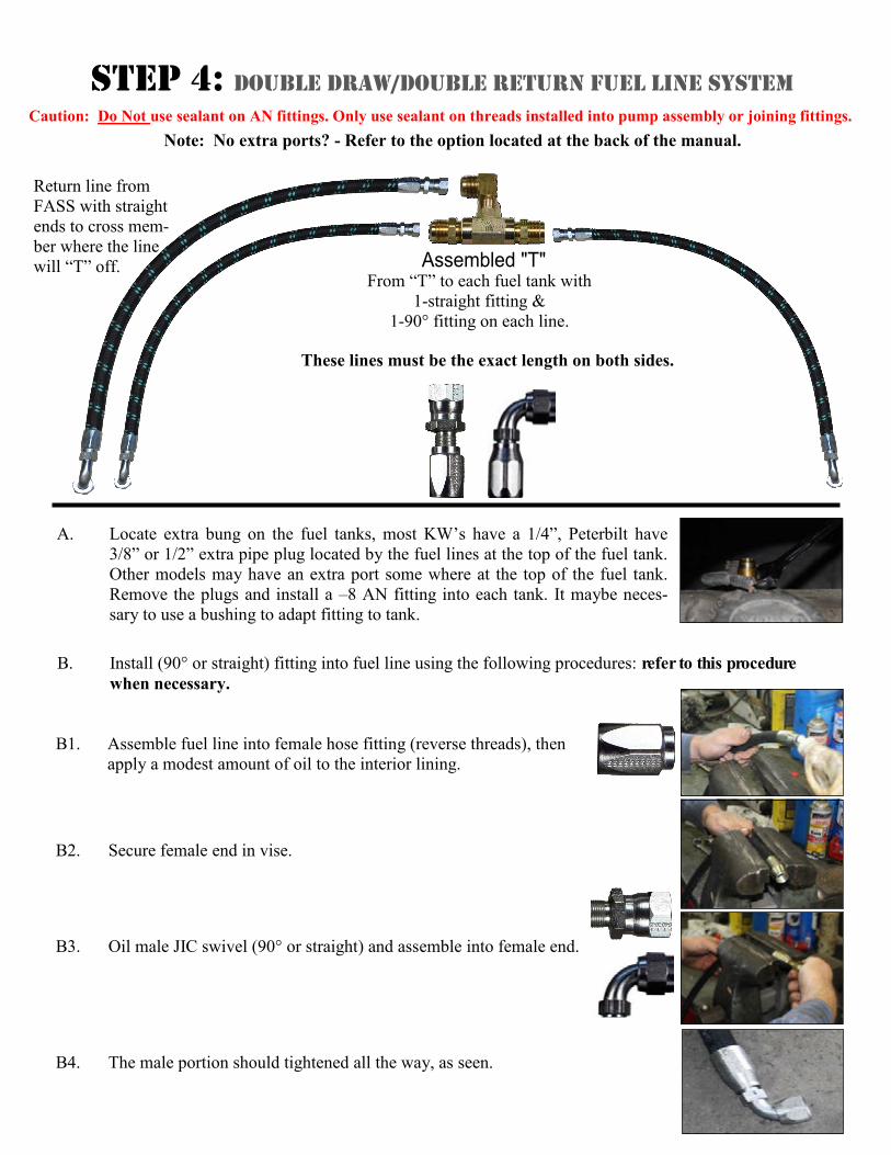
A. Locate extra bung on the fuel tanks, most KW’s have a 1/4”, Peterbilt have
3/8” or 1/2” extra pipe plug located by the fuel lines at the top of the fuel tank.
Other models may have an extra port some where at the top of the fuel tank.
Remove the plugs and install a –8 AN fitting into each tank. It maybe neces-
sary to use a bushing to adapt fitting to tank.
B2. Secure female end in vise.
B4. The male portion should tightened all the way, as seen.
B. Install (90° or straight) fitting into fuel line using the following procedures: refer to this procedure
when necessary.
B1. Assemble fuel line into female hose fitting (reverse threads), then
apply a modest amount of oil to the interior lining.
B3. Oil male JIC swivel (90° or straight) and assemble into female end.
Step 4: Double Draw/Double Return Fuel Line System
Caution: Do Not use sealant on AN fittings. Only use sealant on threads installed into pump assembly or joining fittings.
Note: No extra ports? - Refer to the option located at the back of the manual.
These lines must be the exact length on both sides.
Return line from
FASS with straight
ends to cross mem-
ber where the line
will “T” off. From “T” to each fuel tank with
1-straight fitting &
1-90° fitting on each line.

C. Assemble the “T” using (1) 3/8 NPT ‘T’, (2) -8 ANx3/8 MPT & (1) -8 ANx3/8
MPT 90° as seen in the photo.
J. In the same manner as previously covered, route and loosely connect the assem-
bled fuel lines discussed in this section to the appropriate points of connection
including the ‘T’.
E. Cut the fuel line and assemble a –8 AN hydraulic fitting in the opposite end of
the line connecting to the “R” port of the FASS.
D. Attach the line completed in Step 4b to the return port of the FASS labeled with
an “R”. Route to the center of the nearest cross member aligned with the ports in
the fuel tank being used for return fuel. Measure & mark this line as it will con-
nect to the 90° fitting of the “T” in this location.
K. Torque all connections to 18 ft./lbs. Secure the fuel line and all fittings. Continue
to Step 5
F. Assemble a –8 AN hydraulic fitting into one end of the remaining fuel line.
Route this fuel line from straight fitting of the “T” to the return port in the
fuel tank, mark & cut.
G. Caution: Route the side with the exhaust first as it will be necessary to trav-
el below the frame to avoid the exhaust, each side has to be the exact same
length. Later it will install as seen.
I. Assemble (1) of each –8 AN 90° & -8 AN Straight into each line addressed in
Steps 4f & 4g.
H. Cut the remaining fuel line to the “Exact” same length line as the line in Step 4f.
Step 4: Double Draw/Double Return Fuel Line System

Step 4: Single Draw/Single Return Fuel Line System
B. Install –8 AN hydraulic fitting into fuel line using the following procedures: refer to this procedure
when necessary.
B2. Secure female end in vise.
A. Locate a fuel return port into the fuel tank. Most KW’s have a 1/4”, Peterbilts
have 3/8” or 1/2” extra pipe plug located by the fuel lines at the top of the fuel
tank. Other models may have an extra port some where at the top of the fuel
tank. Remove the plugs and install the –8 ANx5/16 NPT into each tank, it may-
be necessary to use a brass bushing.
B1. Assemble fuel line into female hose fitting (reverse threads), then
apply a modest amount of oil to the interior lining.
B3. Oil male end of 90° JIC swivel fitting and assemble into female end.
B4. The male portion should tightened all the way, as seen.
Caution: Do Not use sealant on AN fittings. Only use sealant on threads installed into pump assembly or joining fittings.
Note: No extra ports? - Refer to the option located at the back of the manual.
Step 4: Single Draw/Single Return Fuel Line System
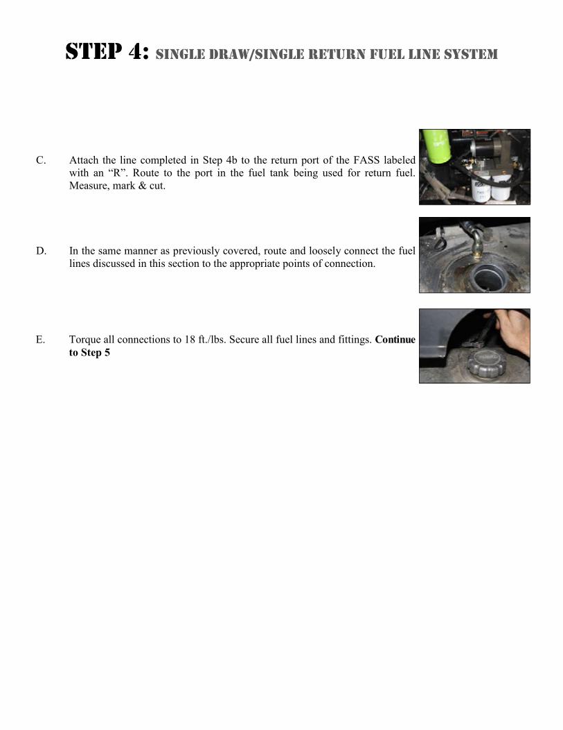
C. Attach the line completed in Step 4b to the return port of the FASS labeled
with an “R”. Route to the port in the fuel tank being used for return fuel.
Measure, mark & cut.
D. In the same manner as previously covered, route and loosely connect the fuel
lines discussed in this section to the appropriate points of connection.
E. Torque all connections to 18 ft./lbs. Secure all fuel lines and fittings. Continue
to Step 5
Step 5: Fuel Supply Line
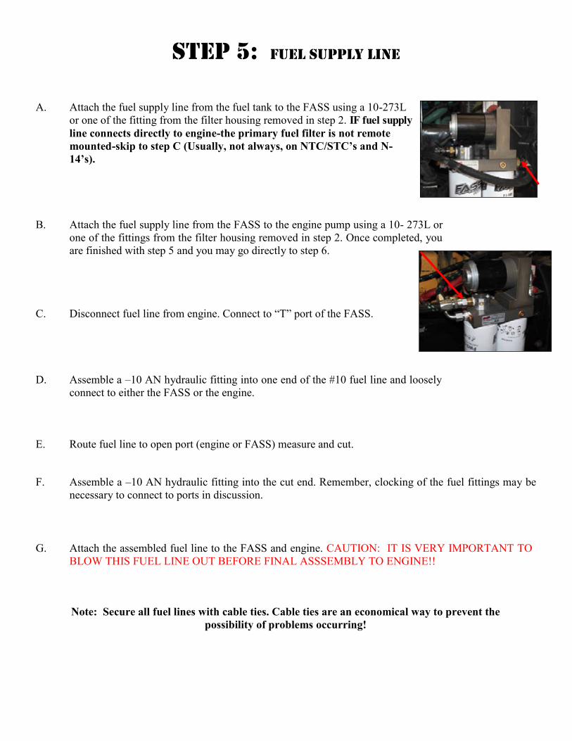
A. Attach the fuel supply line from the fuel tank to the FASS using a 10-273L
or one of the fitting from the filter housing removed in step 2. IF fuel supply
line connects directly to engine-the primary fuel filter is not remote
mounted-skip to step C (Usually, not always, on NTC/STC’s and N-
14’s).
B. Attach the fuel supply line from the FASS to the engine pump using a 10- 273L or
one of the fittings from the filter housing removed in step 2. Once completed, you
are finished with step 5 and you may go directly to step 6.
C. Disconnect fuel line from engine. Connect to “T” port of the FASS.
E. Route fuel line to open port (engine or FASS) measure and cut.
D. Assemble a –10 AN hydraulic fitting into one end of the #10 fuel line and loosely
connect to either the FASS or the engine.
F. Assemble a –10 AN hydraulic fitting into the cut end. Remember, clocking of the fuel fittings may be
necessary to connect to ports in discussion.
G. Attach the assembled fuel line to the FASS and engine. CAUTION: IT IS VERY IMPORTANT TO
BLOW THIS FUEL LINE OUT BEFORE FINAL ASSSEMBLY TO ENGINE!!
Note: Secure all fuel lines with cable ties. Cable ties are an economical way to prevent the
possibility of problems occurring!

B. Secure female end in vise.
D. The male portion should tightened all the way, as seen.
A. Assemble fuel line into female hose fitting (reverse threads), then
apply a modest amount of oil to the interior lining.
C. Oil male JIC swivel (90° or straight) and assemble into female end.
Step 6: Double Vent Line Return System
Caution: Do Not use sealant on AN fittings. Only use sealant on threads installed into pump assembly or joining fittings.
These lines must be the exact length on both sides.
Return line from
FASS with straight
ends to cross member
where the line will
“T” off.
E. Assemble the “T” using (1) 3/8 NPT ‘T’, (2) -8 ANx3/8 MPT & (1) -8 ANx3/8
MPT 90° as seen in the photo.
From “T” to each fuel tank with
2-straight fittings on 2 of the lines going to the Vent Line &
1-90° fitting on Return line connecting to the FASS

L. In the same manner as previously covered, route and loosely connect the assembled fuel lines discussed
in this section to the appropriate points of connection including the ‘T’.
G. Cut the fuel line and assemble a –8 AN hydraulic fitting in the opposite end of
the line connecting to the “R” port of the FASS.
F. Attach the line completed in Step 4b to the return port of the FASS labeled with
an “R”. Route to the center of the nearest cross member aligned with the ports in
the fuel tank being used for return fuel. Measure & mark this line as it will con-
nect to the 90° fitting of the “T” in this location.
M. Torque all connections to 18 ft./lbs. Secure the fuel line and all fittings. Continue to Step 5
H. Assemble a –8 AN hydraulic fitting into one end of the remaining fuel line.
Route this fuel line from straight fitting of the “T” to the return port in the fuel
tank, mark & cut.
I. Caution: Route the side with the exhaust first as it may be necessary to travel below the frame to
avoid the exhaust, each side has to be the exact same length. Later it will install as seen.
J. Cut the remaining fuel line to the “Exact” same length line as the line in Step 4f.
Step 6: Double Vent Line Return System
K. Assemble (2) of each -8 AN Straight into each side of the line addressed in Steps 4f & 4g.

Fuel Tank Vent Line
Fuel Tank
FASS Return
N. Locate Fuel Tank Vent Line and remove vent and vent line from tank. Thread tape reducer on both
ends and install reducer into tank. Once reducer has been secured install “T” onto reducer and secure.
Thread tape bushings and install them on the “T” . NOTE: Not all configurations will be able to be
assembled this way. Install the vent line on the top por tion of the “T” and the FASS return line
into the middle of the “T”. Repeat previous steps on other tank to install the Double Vent Line Return Kit.
Step 6: Double Vent Line Return System
O. The below picture illustrates the configuration previously mentioned..

Step 7: Review Installation & Secure Connections
A. Bolts and fasteners properly tightened?
B. Electrical harness and fuel lines secured and properly tightened?
C. Has the system been primed, refer to owners manual?
D. Check for leaks.
E. Start the engine
F. Recheck all fluid and filter connections for leaks
G. Product registration filled out and ready to be mailed or faxed.
B. Weld a Bung Fitting
1. Fire Hazard, must be accomplished by a professional.
A. Most Preferred & Easiest
1. Drill and tap a 3/8”fpt in the thicker band of aluminum as seen.
2. If possible, install the fuel tank vent in this port and connect the FASS
Option: 2 Ways of Producing Extra Ports (Bung fitting)
Note: The Red Plastic Plugs located in the “H” ports can stay in place fuel will not flow
through these ports. Coolant can be plumbed into these ports to heat the fuel in the Winter
months.
To assist with priming your FASS pump crack the FF-3003. Put power to the FASS pump to
activate the pump. When the tone of the pump changes you can tighten up the fuel filter.

Note: O-Ring must be put back on suction side of pump. Failure to do so can result in
priming issues, cavitation, or pressure loses.
Step 7: Review Installation & Secure Connections
Fuel Filter –Install FF-3003 on
side of pump with draw tube in
the middle of the filter nipple.
Water Separator Filter –Install FS-1001 on water
separator nipple without the draw tube. Make sure
to insert O-Ring provided on nipple.

Filter Cross References
Fuel Filter (Micron Rating) Water Separator (Micron Rating)
Thread Size (1-14) Thread Size (1-14)
Baldwin BF7633 (2M) Baldwin BF 1258 (10M)
Carquest 86528 (2M) Baldwin BF1214
CAT 1P2299 (6M) Baldwin BF7546 (10M)
CAT 1R0750 (2M) Donaldson P558000 (20M)
Donaldson P551025(4M) Donaldson P551000 (10M)
Donaldson P551311 (3M) Donaldson P551001(10M)
Donaldson P551313 (3M) Fleetguard FS1282 (14M)
Donaldson P553203(3M) Fleetguard FS-1000 (10M)
Donaldson P557440 (6M) Fleetguard FS-1001 (10M)
Fleetguard FF5320(2M) Fleetguard FS-1009(14M)
Fram P8334 (2M) Fleetguard FS-1212(14M)
Hastings FF1079 (2M) LuberFiner LFF8011
Wix 33352 (6M) LuberFiner LFF8000
Wix 33528 (2M) Motorcraft FD818 (14M)
Wix 33674 (2M) Wix 33405(14M)
Wix 33522 (10M)
(Currently in use)
Fuel (FWS-3003)
Water (FS-1001)


