5
Bulletin AQ6150SR-01EN Optical Wavelength Meter Optical Wavelength Meter AQ6150 series QUALITY INNOVATION FORESIGHT Fast, Accurate, and Cost-effective
Bulletin AQ6150SR-01EN
Optical Wavelength Meter
Op
tical Wavelen
gth
Meter A
Q6150 series
QUALITY INNOVATION FORESIGHTQUALITY INNOVATION FORESIGHT
Fast, Accurate, and Cost-effective
AQ6150 Series
AQ6150 AQ6151
2 3
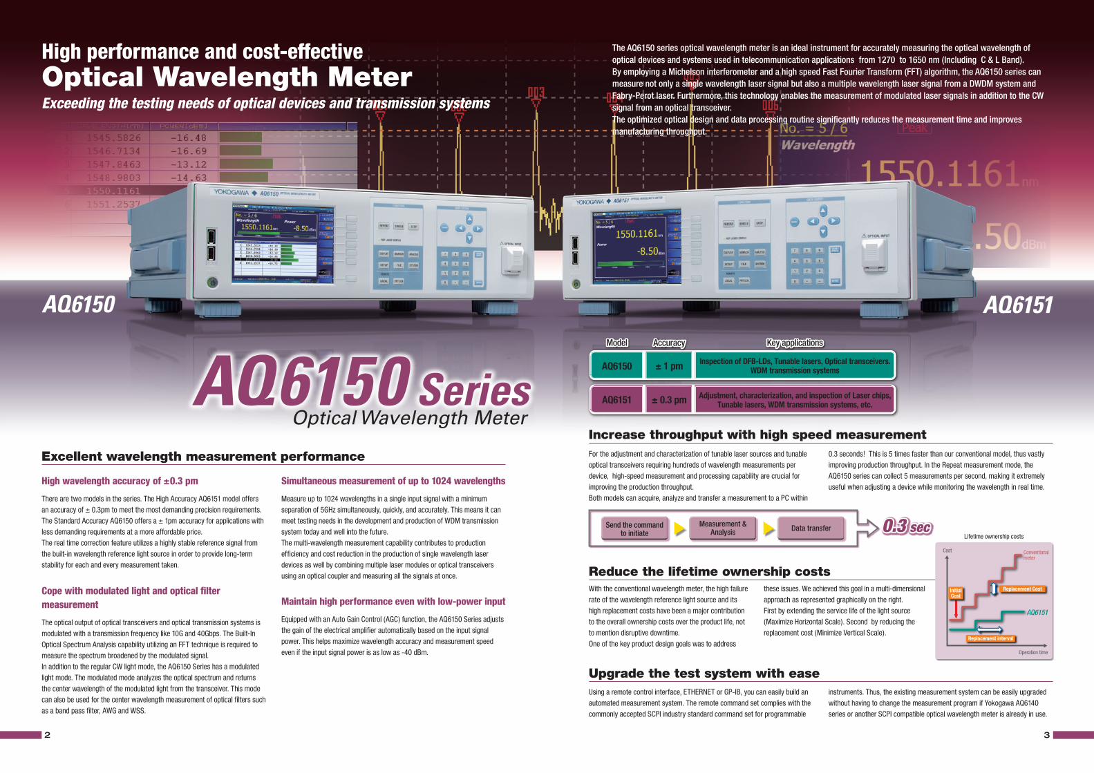
The AQ6150 series optical wavelength meter is an ideal instrument for accurately measuring the optical wavelength of optical devices and systems used in telecommunication applications from 1270 to 1650 nm (Including C & L Band).By employing a Michelson interferometer and a high speed Fast Fourier Transform (FFT) algorithm, the AQ6150 series can measure not only a single wavelength laser signal but also a multiple wavelength laser signal from a DWDM system and Fabry-Perot laser. Furthermore, this technology enables the measurement of modulated laser signals in addition to the CW signal from an optical transceiver.The optimized optical design and data processing routine significantly reduces the measurement time and improves manufacturing throughput.
High wavelength accuracy of ±0.3 pm
There are two models in the series. The High Accuracy AQ6151 model offers an accuracy of ± 0.3pm to meet the most demanding precision requirements. The Standard Accuracy AQ6150 offers a ± 1pm accuracy for applications with less demanding requirements at a more affordable price.The real time correction feature utilizes a highly stable reference signal from the built-in wavelength reference light source in order to provide long-term stability for each and every measurement taken.
Cope with modulated light and optical filter measurement
The optical output of optical transceivers and optical transmission systems is modulated with a transmission frequency like 10G and 40Gbps. The Built-In Optical Spectrum Analysis capability utilizing an FFT technique is required to measure the spectrum broadened by the modulated signal.In addition to the regular CW light mode, the AQ6150 Series has a modulated light mode. The modulated mode analyzes the optical spectrum and returns the center wavelength of the modulated light from the transceiver. This mode can also be used for the center wavelength measurement of optical filters such as a band pass filter, AWG and WSS.
Excellent wavelength measurement performance
Increase throughput with high speed measurement
Reduce the lifetime ownership costs
Upgrade the test system with ease
Simultaneous measurement of up to 1024 wavelengths
Measure up to 1024 wavelengths in a single input signal with a minimum separation of 5GHz simultaneously, quickly, and accurately. This means it can meet testing needs in the development and production of WDM transmission system today and well into the future. The multi-wavelength measurement capability contributes to production efficiency and cost reduction in the production of single wavelength laser devices as well by combining multiple laser modules or optical transceivers using an optical coupler and measuring all the signals at once.
Maintain high performance even with low-power input
Equipped with an Auto Gain Control (AGC) function, the AQ6150 Series adjusts the gain of the electrical amplifier automatically based on the input signal power. This helps maximize wavelength accuracy and measurement speed even if the input signal power is as low as -40 dBm.
For the adjustment and characterization of tunable laser sources and tunable optical transceivers requiring hundreds of wavelength measurements per device, high-speed measurement and processing capability are crucial for improving the production throughput.Both models can acquire, analyze and transfer a measurement to a PC within
With the conventional wavelength meter, the high failure rate of the wavelength reference light source and its high replacement costs have been a major contribution to the overall ownership costs over the product life, not to mention disruptive downtime.One of the key product design goals was to address
Using a remote control interface, ETHERNET or GP-IB, you can easily build an automated measurement system. The remote command set complies with the commonly accepted SCPI industry standard command set for programmable
0.3 seconds! This is 5 times faster than our conventional model, thus vastly improving production throughput. In the Repeat measurement mode, the AQ6150 series can collect 5 measurements per second, making it extremely useful when adjusting a device while monitoring the wavelength in real time.
instruments. Thus, the existing measurement system can be easily upgraded without having to change the measurement program if Yokogawa AQ6140 series or another SCPI compatible optical wavelength meter is already in use.
High performance and cost-effectiveOptical Wavelength MeterExceeding the testing needs of optical devices and transmission systems
Optical Wavelength Meter
Model Accuracy Key applications
AQ6150 ± 1 pm Inspection of DFB-LDs, Tunable lasers, Optical transceivers. WDM transmission systems
AQ6151 ± 0.3 pm Adjustment, characterization, and inspection of Laser chips, Tunable lasers, WDM transmission systems, etc.
Model Accuracy Key applications
these issues. We achieved this goal in a multi-dimensional approach as represented graphically on the right. First by extending the service life of the light source (Maximize Horizontal Scale). Second by reducing the replacement cost (Minimize Vertical Scale).
Send the commandto initiate
Measurement & Analysis Data transfer 0.3 sec
Lifetime ownership costs
AQ6151
Replacement Cost
Conventional meter
Cost
Operation time
Replacement interval
InitialCost
4 5
AQ6150 seriesOptical Wavelength Meter
Various view modes Efficient measurement & analysis functions
User-friendly interfaces
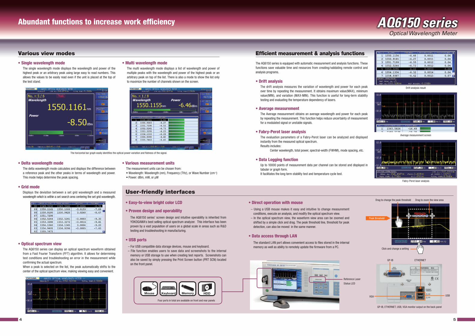
• Single wavelength mode The single wavelength mode displays the wavelength and power of the
highest peak or an arbitrary peak using large easy to read numbers. This allows the values to be easily read even if the unit is placed at the top of the test stand.
• Average measurement The Average measurement obtains an average wavelength and power for each peak
by repeating the measurement. This function helps reduce uncertainty of measurement for a modulated signal or unstable signals.
• Drift analysis The drift analysis measures the variation of wavelength and power for each peak
over time by repeating the measurement. It obtains maximum value(MAX), minimum value(MIN), and variation (MAX-MIN). This function is useful for long-term stability testing and evaluating the temperature dependency of lasers.
• Fabry-Perot laser analysis The evaluation parameters of a Fabry-Perot laser can be analyzed and displayed
instantly from the measured optical spectrum. Results includes: Center wavelength, total power, spectral-width (FWHM), mode spacing, etc.
• Delta wavelength mode The delta wavelength mode calculates and displays the difference between
a reference peak and the other peaks in terms of wavelength and power. This mode helps determine the peak spacing.
• Grid mode Displays the deviation between a set grid wavelength and a measured
wavelength which is within a set search area centering the set grid wavelength.
• Easy-to-view bright color LCD
• Proven design and operability The AQ6150 series’ screen design and intuitive operability is inherited from
YOKOGAWA‘s best selling optical spectrum analyzer. This interface has been proven by a vast population of users on a global scale in areas such as R&D testing and troubleshooting in manufacturing.
• USB ports – For USB compatible data storage devices, mouse and keyboard. – File function enables users to save data and screenshots to the internal
memory or USB storage to use when creating test reports. Screenshots can also be saved by simply pressing the Print Screen button (PRT SCN) located on the front panel.
• Direct operation with mouse – Using a USB mouse makes it easy and intuitive to change measurement
conditions, execute an analysis, and modify the optical spectrum view. – In the optical spectrum view, the waveform view area can be zoomed and
shifted by a simple click and drag. The peak threshold line, threshold for peak detection, can also be moved in the same manner.
• Data access through LAN The standard LAN port allows convenient access to files stored in the internal
memory as well as ability to remotely update the firmware from a PC.• Optical spectrum view The AQ6150 series can display an optical spectrum waveform obtained
from a Fast Fourier Transform (FFT) algorithm. It allows for determining test conditions and troubleshooting an error in the measurement while confirming the actual spectrum.
When a peak is selected on the list, the peak automatically shifts to the center of the optical spectrum view, making viewing easy and convenient.
• Multi wavelength mode The multi wavelength mode displays a list of wavelength and power of
multiple peaks with the wavelength and power of the highest peak or an arbitrary peak on top of the list. There is also a mode to show the list only to maximize the number of channels shown on the screen.
• Various measurement units The measurement units can be chosen from: • Wavelength: Wavelength (nm), Frequency (THz), or Wave Number (cm-1) • Power: dBm, mW, or µW
The horizontal bar graph easily identifies the optical power variation and flatness of the signal.
Drift analysis result
Average measurement screen
GP-IB, ETHERNET, USB, VGA monitor output on the back panel
Four ports in total are available on front and rear panels
The AQ6150 series is equipped with automatic measurement and analysis functions. These functions save valuable time and resources from creating/validating remote control and analysis programs.
Abundant functions to increase work efficiency
Drag to change the peak threshold
Peak threshold
Drag to zoom the view area
Click and change a setting
Mouse Memory HDDKeyboard
Fabry-Perot laser analysis
Reference Laser
Status LED
GP-IB ETHERNET
USBVGA
• Data Logging function Up to 10000 points of measurement data per channel can be stored and displayed in
tabular or graph form. It facilitates the long term stability test and temperature cycle test.
6 7
AQ6150 seriesOptical Wavelength Meter
Applications Major specifications
Principle
• WDM transmission systems In order to meet the rigorous demands of
current and next generation communication ne t works, developer s a re cons t an t ly challenged to improve the ef ficiency and capacity of the transmission system. In response to these challenges, var ious techniques have been developed, such as minimizing channel spacing, maximizing the number of channels and transmission rate, using sophisticated modulation schemes, etc.
In WDM transmission system testing, high wavelength accuracy is required for testing the system’s internal circuit boards such as laser modules and optical transceivers as well as the final output signal of the system.
– Simultaneous measurement of multi channel and narrow spacing WDM system
– Precise adjustment and inspection of laser sources
– Measurement of modulated signals
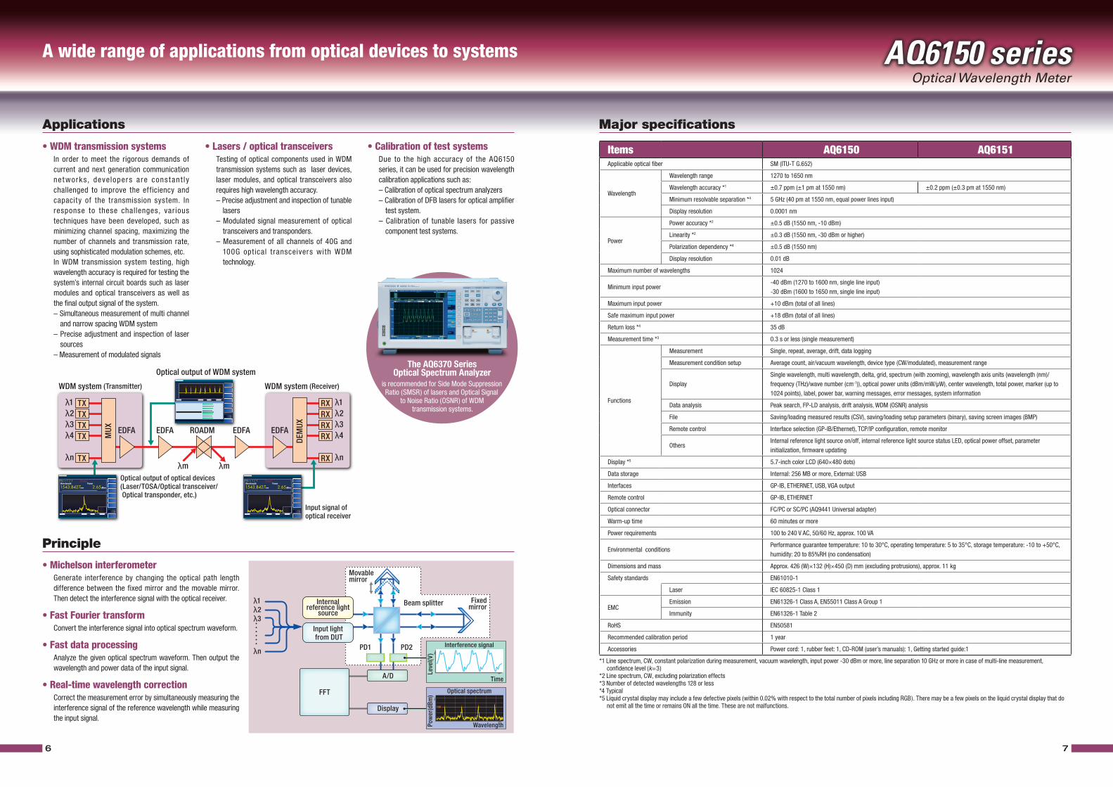
• Michelson interferometer Generate interference by changing the optical path length
difference between the fixed mirror and the movable mirror. Then detect the interference signal with the optical receiver.
• Fast Fourier transform Convert the interference signal into optical spectrum waveform.
• Fast data processing Analyze the given optical spectrum waveform. Then output the
wavelength and power data of the input signal.
• Real-time wavelength correction Correct the measurement error by simultaneously measuring the
interference signal of the reference wavelength while measuring the input signal.
• Lasers / optical transceivers Testing of optical components used in WDM
transmission systems such as laser devices, laser modules, and optical transceivers also requires high wavelength accuracy.
– Precise adjustment and inspection of tunable lasers
– Modulated signal measurement of optical transceivers and transponders.
– Measurement of all channels of 40G and 100G optical transceivers with WDM technology.
• Calibration of test systems Due to the high accuracy of the AQ6150
series, it can be used for precision wavelength calibration applications such as:
– Calibration of optical spectrum analyzers – Calibration of DFB lasers for optical amplifier
test system. – Calibration of tunable lasers for passive
component test systems.
A wide range of applications from optical devices to systems
is recommended for Side Mode Suppression Ratio (SMSR) of lasers and Optical Signal
to Noise Ratio (OSNR) of WDM transmission systems.
Wavelength Power
2.65dBm
No = 1 / 1 Peak
1543.8427nm
Wavelength Power
2.65dBm
No = 1 / 1 Peak
1543.8427nm
WDM system (Transmitter)
TXTX
EDFATX
MUX
TX
TX
λ1λ2λ3λ4
λn
RXRXRX
DEM
UX
RX
RX
λ1λ2λ3λ4
λnλmλm
WDM system (Receiver)
Optical output of WDM system
Optical output of optical devices(Laser/TOSA/Optical transceiver/ Optical transponder, etc.)
Input signal of optical receiver
EDFA ROADM EDFA EDFA
THR
Movablemirror
Fixedmirror
Internalreference light
source
Input light from DUT
PD1
FFT
PD2
A/D
Display
Pow
er(d
Bm)
Wavelength
Optical spectrum
Beam splitter
Leve
l(V)
Time
Interference signal
λ1λ2λ3
λn
The AQ6370 SeriesOptical Spectrum Analyzer
Items AQ6150 AQ6151Applicable optical fiber SM (ITU-T G.652)
Wavelength
Wavelength range 1270 to 1650 nm
Wavelength accuracy *1 ±0.7 ppm (±1 pm at 1550 nm) ±0.2 ppm (±0.3 pm at 1550 nm)
Minimum resolvable separation *4 5 GHz (40 pm at 1550 nm, equal power lines input)
Display resolution 0.0001 nm
Power
Power accuracy *2 ±0.5 dB (1550 nm, -10 dBm)
Linearity *2 ±0.3 dB (1550 nm, -30 dBm or higher)
Polarization dependency *4 ±0.5 dB (1550 nm)
Display resolution 0.01 dB
Maximum number of wavelengths 1024
Minimum input power-40 dBm (1270 to 1600 nm, single line input)-30 dBm (1600 to 1650 nm, single line input)
Maximum input power +10 dBm (total of all lines)
Safe maximum input power +18 dBm (total of all lines)
Return loss *4 35 dB
Measurement time *3 0.3 s or less (single measurement)
Functions
Measurement Single, repeat, average, drift, data logging
Measurement condition setup Average count, air/vacuum wavelength, device type (CW/modulated), measurement range
DisplaySingle wavelength, multi wavelength, delta, grid, spectrum (with zooming), wavelength axis units (wavelength (nm)/frequency (THz)/wave number (cm-1)), optical power units (dBm/mW/µW), center wavelength, total power, marker (up to 1024 points), label, power bar, warning messages, error messages, system information
Data analysis Peak search, FP-LD analysis, drift analysis, WDM (OSNR) analysis
File Saving/loading measured results (CSV), saving/loading setup parameters (binary), saving screen images (BMP)
Remote control Interface selection (GP-IB/Ethernet), TCP/IP configuration, remote monitor
OthersInternal reference light source on/off, internal reference light source status LED, optical power offset, parameter initialization, firmware updating
Display *5 5.7-inch color LCD (640×480 dots)
Data storage Internal: 256 MB or more, External: USB
Interfaces GP-IB, ETHERNET, USB, VGA output
Remote control GP-IB, ETHERNET
Optical connector FC/PC or SC/PC (AQ9441 Universal adapter)
Warm-up time 60 minutes or more
Power requirements 100 to 240 V AC, 50/60 Hz, approx. 100 VA
Environmental conditionsPerformance guarantee temperature: 10 to 30°C, operating temperature: 5 to 35°C, storage temperature: -10 to +50°C, humidity: 20 to 85%RH (no condensation)
Dimensions and mass Approx. 426 (W)×132 (H)×450 (D) mm (excluding protrusions), approx. 11 kg
Safety standards EN61010-1
Laser IEC 60825-1 Class 1
EMCEmission EN61326-1 Class A, EN55011 Class A Group 1
Immunity EN61326-1 Table 2
RoHS EN50581
Recommended calibration period 1 year
Accessories Power cord: 1, rubber feet: 1, CD-ROM (user’s manuals): 1, Getting started guide:1
*1 Line spectrum, CW, constant polarization during measurement, vacuum wavelength, input power -30 dBm or more, line separation 10 GHz or more in case of multi-line measurement, confidence level (k=3)*2 Line spectrum, CW, excluding polarization effects*3 Number of detected wavelengths 128 or less*4 Typical*5 Liquid crystal display may include a few defective pixels (within 0.02% with respect to the total number of pixels including RGB). There may be a few pixels on the liquid crystal display that do
not emit all the time or remains ON all the time. These are not malfunctions.
AQ6150 seriesOptical Wavelength Meter
* Any company’s names and product names mentioned in this document are trade names, trademarks or registered trademarks of their respective companies.
* "Typical" or “Typ." in this document means "Typical value", which is for reference, not guaranteed specification.
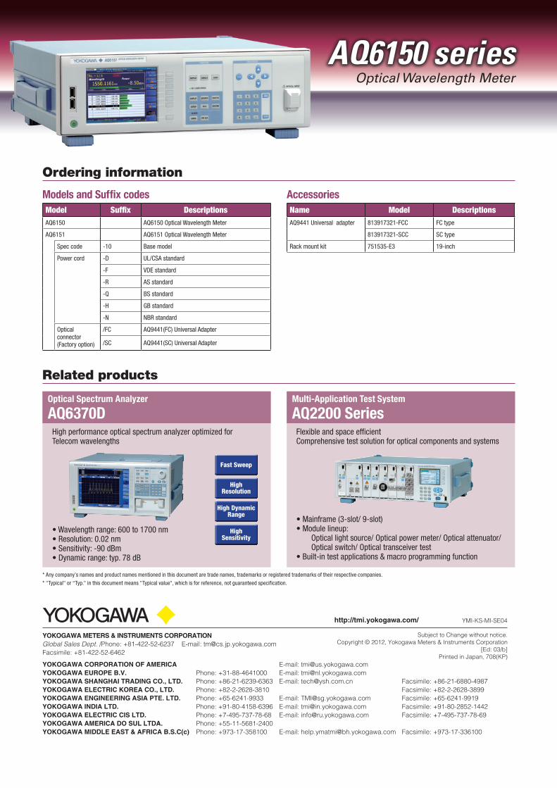
• Wavelength range: 600 to 1700 nm• Resolution: 0.02 nm• Sensitivity: -90 dBm• Dynamic range: typ. 78 dB
Models and Suffix codes Accessories
Ordering information
Related products
Model Suffix DescriptionsAQ6150 AQ6150 Optical Wavelength Meter
AQ6151 AQ6151 Optical Wavelength Meter
Spec code -10 Base model
Power cord -D UL/CSA standard
-F VDE standard
-R AS standard
-Q BS standard
-H GB standard
-N NBR standard
Opticalconnector(Factory option)
/FC AQ9441(FC) Universal Adapter
/SC AQ9441(SC) Universal Adapter
Name Model DescriptionsAQ9441 Universal adapter 813917321-FCC FC type
813917321-SCC SC type
Rack mount kit 751535-E3 19-inch
Multi-Application Test System
AQ2200 SeriesOptical Spectrum Analyzer
AQ6370DHigh performance optical spectrum analyzer optimized for Telecom wavelengths
Fast Sweep
High Resolution
High Dynamic Range
High Sensitivity
Flexible and space efficientComprehensive test solution for optical components and systems
• Mainframe (3-slot/ 9-slot)• Module lineup: Optical light source/ Optical power meter/ Optical attenuator/ Optical switch/ Optical transceiver test• Built-in test applications & macro programming function
Subject to Change without notice.Copyright © 2012, Yokogawa Meters & Instruments Corporation
[Ed: 03/b]Printed in Japan, 708(KP)
YOKOGAWA CORPORATION OF AMERICA E-mail: [email protected] YOKOGAWA EUROPE B.V. Phone: +31-88-4641000 E-mail: [email protected] YOKOGAWA SHANGHAI TRADING CO., LTD. Phone: +86-21-6239-6363 E-mail: [email protected] Facsimile: +86-21-6880-4987YOKOGAWA ELECTRIC KOREA CO., LTD. Phone: +82-2-2628-3810 Facsimile: +82-2-2628-3899YOKOGAWA ENGINEERING ASIA PTE. LTD. Phone: +65-6241-9933 E-mail: [email protected] Facsimile: +65-6241-9919 YOKOGAWA INDIA LTD. Phone: +91-80-4158-6396 E-mail: [email protected] Facsimile: +91-80-2852-1442YOKOGAWA ELECTRIC CIS LTD. Phone: +7-495-737-78-68 E-mail: [email protected] Facsimile: +7-495-737-78-69YOKOGAWA AMERICA DO SUL LTDA. Phone: +55-11-5681-2400 YOKOGAWA MIDDLE EAST & AFRICA B.S.C(c) Phone: +973-17-358100 E-mail: [email protected] Facsimile: +973-17-336100
YMI-KS-MI-SE04
YOKOGAWA METERS & INSTRUMENTS CORPORATIONGlobal Sales Dept. /Phone: +81-422-52-6237 E-mail: [email protected] Facsimile: +81-422-52-6462
http://tmi.yokogawa.com/


