Fast and reliable handoff for vehicular networks Zohar Naor Department of Mathematics, Physics, and Computer Science, University of Haifa, Israel article info Article history: Available online 18 May 2012 Keywords: Vehicular networks Mobility management Mobility anchor point Fast and reliable handoff abstract A layer-3 mobility management scheme for an all-IP Wireless Access Network (WAN), and in particular for vehicular networks, is developed in this paper. The proposed method enables fast and reliable handoff. This feature is extremely important for high speed vehic- ular networks. Since vehicles are characterized by likely-predictable path, as well as very high speed, handoff events can and should be predicted in order to achieve fast and reliable handoff. As it is shown in this study, the proposed scheme can significantly reduce the packet loss ratio caused by frequent handoff events experienced by high speed vehicles. This scheme is topology-independent in the sense that it does not assume any network topology. The key idea is to use a topology-learning algorithm that enables to perform localized mobility management, by efficiently re-selecting a Mobility Anchor Point (MAP) node. The goal of the proposed scheme is to maintain a continues connection subject to user-dependent delay constraints, while minimizing the signaling cost and packet loss ratio associated with handoff events. This scheme is consistent with the existing mobility management schemes currently used in Mobile IP (MIP) and cellular networks, and it fits into the Hierarchical Mobile IPv6 (HMIPv6) scheme defined in Mobile IPv6 (MIPv6) for integrating mobile terminals with the Internet wired backbone. Ó 2012 Elsevier B.V. All rights reserved. 1. Introduction The expected deployment of vehicular networks creates a new challenge to a proper design of mobility management scheme for such networks. Existing mobility management schemes are not optimal for these networks, since vehicles are expected to perform frequent handoff procedures while moving either from one base station to another, or from one system to another. For instance, high speed vehicles may experienced frequent layer-3 handoff events caused by in- ter-system handovers. These frequent handoff events are associated with packets loss and session discontinuity. The key idea in this study is to use topology learning com- bined with path prediction in order to foresee handoff events, and then to allocate the required wireless resources and conduct a soft layer-3 handoff. Mobile IPv4 (MIPv4) is not suitable for high mobility devices, since they are required to perform too many tasks of registration and deregistration. We consider a vehicular network (VN) which consists of Base stations (BSs), stationary Access Points (APs) to the Internet infrastructure and Mobile Ter- minals (MTs). An AP is a radio repeater used to provide Internet access to the MT. The term MT refers to any wire- less mobile device, for instance a vehicle. While the BSs and APs are static, an MT may roam across the system geo- graphic coverage area, and from one system to another. An MT may access an AP either directly, or via another MT, for instance a vehicle, to be used as an access router (AR) to the AP. Each AP is also an AR. The main concern of this study is on tracking the location of the MT across a VN, while keeping a continues connectivity between the MT and the wired network backbone. Mobile IP (MIP) supports mobility by specialized routers known as mobility agents. There are two types of mobility agents – the home agent and the foreign agent. The home agent is associated with the MT home network, and points to the foreign agent, which handles the care-of-address of the MT current location. Foreign agents are not required in MIPv6. The criterion for updating the home agent is left 1570-8705/$ - see front matter Ó 2012 Elsevier B.V. All rights reserved. http://dx.doi.org/10.1016/j.adhoc.2012.05.002 E-mail address: [email protected]Ad Hoc Networks 11 (2013) 2136–2145 Contents lists available at SciVerse ScienceDirect Ad Hoc Networks journal homepage: www.elsevier.com/locate/adhoc
Transcript
Ad Hoc Networks 11 (2013) 2136–2145
Contents lists available at SciVerse ScienceDirect
Ad Hoc Networks
journal homepage: www.elsevier .com/locate /adhoc
Fast and reliable handoff for vehicular networks
1570-8705/$ - see front matter � 2012 Elsevier B.V. All rights reserved.http://dx.doi.org/10.1016/j.adhoc.2012.05.002
Zohar NaorDepartment of Mathematics, Physics, and Computer Science, University of Haifa, Israel
a r t i c l e i n f o
Article history:Available online 18 May 2012
Keywords:Vehicular networksMobility managementMobility anchor pointFast and reliable handoff
a b s t r a c t
A layer-3 mobility management scheme for an all-IP Wireless Access Network (WAN), andin particular for vehicular networks, is developed in this paper. The proposed methodenables fast and reliable handoff. This feature is extremely important for high speed vehic-ular networks. Since vehicles are characterized by likely-predictable path, as well as veryhigh speed, handoff events can and should be predicted in order to achieve fast and reliablehandoff. As it is shown in this study, the proposed scheme can significantly reduce thepacket loss ratio caused by frequent handoff events experienced by high speed vehicles.This scheme is topology-independent in the sense that it does not assume any networktopology. The key idea is to use a topology-learning algorithm that enables to performlocalized mobility management, by efficiently re-selecting a Mobility Anchor Point(MAP) node. The goal of the proposed scheme is to maintain a continues connection subjectto user-dependent delay constraints, while minimizing the signaling cost and packet lossratio associated with handoff events. This scheme is consistent with the existing mobilitymanagement schemes currently used in Mobile IP (MIP) and cellular networks, and it fitsinto the Hierarchical Mobile IPv6 (HMIPv6) scheme defined in Mobile IPv6 (MIPv6) forintegrating mobile terminals with the Internet wired backbone.
� 2012 Elsevier B.V. All rights reserved.
1. Introduction deregistration. We consider a vehicular network (VN)
The expected deployment of vehicular networks createsa new challenge to a proper design of mobility managementscheme for such networks. Existing mobility managementschemes are not optimal for these networks, since vehiclesare expected to perform frequent handoff procedures whilemoving either from one base station to another, or from onesystem to another. For instance, high speed vehicles mayexperienced frequent layer-3 handoff events caused by in-ter-system handovers. These frequent handoff events areassociated with packets loss and session discontinuity.The key idea in this study is to use topology learning com-bined with path prediction in order to foresee handoffevents, and then to allocate the required wireless resourcesand conduct a soft layer-3 handoff. Mobile IPv4 (MIPv4) isnot suitable for high mobility devices, since they arerequired to perform too many tasks of registration and
which consists of Base stations (BSs), stationary AccessPoints (APs) to the Internet infrastructure and Mobile Ter-minals (MTs). An AP is a radio repeater used to provideInternet access to the MT. The term MT refers to any wire-less mobile device, for instance a vehicle. While the BSs andAPs are static, an MT may roam across the system geo-graphic coverage area, and from one system to another.An MT may access an AP either directly, or via anotherMT, for instance a vehicle, to be used as an access router(AR) to the AP. Each AP is also an AR. The main concern ofthis study is on tracking the location of the MT across aVN, while keeping a continues connectivity between theMT and the wired network backbone.
Mobile IP (MIP) supports mobility by specialized routersknown as mobility agents. There are two types of mobilityagents – the home agent and the foreign agent. The homeagent is associated with the MT home network, and pointsto the foreign agent, which handles the care-of-address ofthe MT current location. Foreign agents are not requiredin MIPv6. The criterion for updating the home agent is left
Z. Naor / Ad Hoc Networks 11 (2013) 2136–2145 2137
open, and depends on network parameters, such as delayand QoS. The mobility management in MIPv6 is brokendown into localized mobility management and globalmobility management. However, MIPv6 does not addressthe issue of handling the local mobility. Instead, it usesthe same mechanism for both global as well as local mobil-ity. Hierarchical MIPv6 (HMIPv6) has been proposed forlocalized mobility management. A new node in HMIPv6called the Mobility Anchor Point (MAP) is used as local en-tity to help performing a mobile handoff. The MAP, whichreplaces the MIPv4 foreign agent, can be located anywherewithin a hierarchy of routers. In contrast to the foreignagent, the MAP does not have to reside on each sub-net.However, the conditions under which the MT should re-se-lect a new MAP are left open, and are not addressed inHMIPv6 [2]. Since re-selecting the MAP is crucial for mini-mizing the handoff-related latency as well as the signalingassociated with MAP re-selection, the MAP replacementalgorithm is essential for conducting an efficient mobilitymanagement scheme. This algorithm is the main contribu-tion of this paper.
Recently proxy mobile IPv6 (PMIPv6), a network-basedmobility management protocol standardized by IETF,which is specified in [13] was proposed. Contrary to MobileIP approach, this protocol is implemented by the network,which is responsible for tracking the movements of the MTand initiating the required mobility signaling. This protocolis based on two main entities: Local Mobility Anchor (LMA)and Mobile Access Gateway (MAG). However, this protocolcan be implemented only on PMIPv6 networks.
1.1. Related works
The problem of enabling fast and reliable handoff is wellstudied, and many schemes were suggested in order to han-dle this problem. In [7] a fast handoff scheme based onmobility prediction was proposed. A selective neighborcaching scheme for fast handoff was suggested in [8]. Ascheme called SyncScan was proposed in [12] for IEEE802.11 networks. This scheme is based on continuouslytracking nearby base stations by synchronizing short listen-ing periods. Unfortunately, all these schemes are not appli-cable for vehicular networks, since they rely on directsensing of the BS by the MT. Unfortunately, very often thevehicle may communicate with its BS via another vehicle,using vehicle-to-vehicle (V2V) communication, or via an-other device, using vehicle-to-roadside (V2R) communica-tion. A network mobility protocol for vehicular ad hocnetworks was proposed in [14]. The key idea in [14] is touse vehicle-to-vehicle communication in order to obtainthe IP address of the next BS from other vehicles beforethe actual handoff. However, this method considers onlylayer-2 handoff, and does not consider layer-3 handoff. Inthis study it is argued that due to the relatively high veloc-ity of a typical vehicle, the best location managementscheme is to select a static node that can be used as the bestMobility Anchor Point (MAP), as defined in HMIPv6 [2]. Theissue of selecting the appropriate MAP has been addressedby several studies. These studies use heuristic algorithms tochoose the most appropriate MAP node, based on pre-assumptions about the MT mobility. The specification of
HMIPv6 [2] recommends to select the furthest MAP, in or-der to reduce the expected rate of re-registration events.This scheme is especially suitable for high mobility MTs,which are delay-tolerant. However, for a low mobility MT,that does not change its location, this scheme is inefficient.In addition, this scheme is not recommended for delay sen-sitive MTs. Another weakness of this scheme is that it maycause all the MTs residing in the same area to select thesame MAP node, which would become a point of perfor-mance bottleneck. The result would be a significant mes-sage delivery latency, caused by the high processing loadimposed on the MAP. An alternative scheme, proposed in[9], is to announce the MAP’s information, such as the traf-fic load on the MAP, in order to enable the MTs to performload-balanced MAP selection. A mobility-based MAP selec-tion schemes were proposed in [3,10]. The idea is that fastMTs select the furthest MAP, while the slow MTs selectthe nearest MAP. This scheme is useful for very fast MTsand very slow MTs, but for MTs in between (i.e. for moder-ate mobility MTs), it does not provide a good solution. Allthese studies mentioned above do not address the issueof MAP replacement, and assume that MAP re-selectionshould occur when the existing MAP is no longer valid(e.g., due to inter-system handover). To the best of ourknowledge, this study is one of the first attempts to enable,under certain conditions, replacing the MAP while it is stillvalid, in order to avoid packets loss due to handoff. Mostimportantly, all these studies cited above are applicableonly in HMIPv6 [2] networks. Due to the slow deploymentof HMIPv6 networks we cannot assume that a vehicularnetwork should be an HMIPv6 network.
A linked list (LL) of forwarding pointers was suggestedin [1,4,11,6]. The key idea is that instead of replacing theMAP, a linked list of pointers is established between the ac-cess routers along the MT roaming path. The LL scheme re-duces the rate of updating the home agent, at the expenseof increasing the expected delay of routing information tothe MT. Thus, it is not suitable for delay-sensitive MTs.
1.2. The contribution of this work
Existing MAP-based mobility management schemesmust be implemented on HMIPv6 networks, since they relyon the MAP announcement broadcasted by the potentialMAP nodes. Moreover, these schemes are based on dis-tance-based algorithms that rely on the DISTANCE field inthe router advertisement message. Due to the relativelyslow deployment of HMIPv6 networks, most of the compo-nents of existing IP networks support IPv4, and thereforethey cannot support these mobility management schemes.In particular, a vehicular network can be very often a heter-ogeneous network which may contain IPv4 as well asHMIPv6 components, owned by different operators. Theproposed method enables the MT to autonomously computeits distance from the potential candidates to become itsMAP node, and then to select the node which is the mostappropriate for its needs. According to our scheme, theMAP node should not be necessarily tracked directly bythe MT (i.e., the vehicle), as it is done in [7,8,12]. Rather,the MT can access its MAP node via another device, usingV2V and V2R communications. Since our scheme is
Domain of MAP1
MAP1 MAP2
Domain of MAP2
AP1 AP2 AP3 AP4 AP5
Fig. 1. The proposed mobility management scheme.
2138 Z. Naor / Ad Hoc Networks 11 (2013) 2136–2145
implemented in the network layer, the MT (i.e., the vehicle)can select its MAP node ahead of time, before it can directlysense its signals. In this sense, the proposed scheme is supe-rior to the fast handoff schemes described in [7,8,12]. Mostimportantly, the proposed scheme can be implemented onany all-IP wireless network. For instance, in IPv4 networksthe MT uses its foreign agent as its local sub-net forwardingserver, similarly to the MAP node. Moreover, while the ideaof using MAP for mobility management in IP networks hasbeen discussed very intensively, a relatively less effort hasbeen made in considering the criterions under which anexisting MAP node should be replaced by another MAPnode. To the best of our knowledge, this study is one ofthe first attempts to initiate, under certain conditions,MAP replacement while the existing MAP is still valid, in or-der to avoid packets loss due to MAP replacement. This fea-ture is especially important for high speed vehicles.Moreover, existing mobility management schemes are notsuitable for high speed vehicles. MIP is not optimized forsuch networks, since it uses an always-update strategy.Consequently, the amount of signaling required by thisscheme, and the packet loss ratio associated with thisscheme is too high, when it is implemented for high speedvehicles. MIPv6 does not address the issue of local mobility,and uses the same mechanism used for global mobility.HMIPv6 [2] addresses local mobility by using a MAP node,but does not define the conditions under which a validMAP node should be replaced. Thus, a MAP node is re-se-lected only upon moving out of the domain of the existingMAP node. Consequently, MAP replacement is associatedwith a handoff event, that may lead to a severe loss of pack-ets. The key idea of the proposed method is to use a topol-ogy-learning algorithm, in order to foresee MAPreplacement, and then to conduct soft handoff. This studyproposes a local mobility management scheme, especiallysuitable for vehicles, in which the MAP re-selection processis adjusted to both the network topology, as well as to theuser mobility and end-to-end connectivity and delay con-straints. This scheme is especially suitable for delay-sensi-tive applications, such as mobile video streaming, thatrequire low handoff-related latency, and for high mobilityterminals, such as vehicles. Partial results of this study werepresented in [5]. However, more than half of this study isnew. For instance, most of the analysis in this study, includ-ing all the proofs and Eqs. (2)–(20), and most of the simula-tion results, did not appear in [5].
1.3. Paper organization
The rest of this paper is organized as follows. The pro-posed mobility management scheme is introduced in Sec-tion 2. Analysis is given in Section 3, and simulation resultsare provided in Section 4. Finally, summary and concludingremarks are given in Section 5.
2. The proposed mobility management scheme
This work suggests a novel layer-3 mobility manage-ment scheme for all-IP vehicular networks. The key ideais that the MT uses a topology learning algorithm combinedwith path prediction in order to conduct a single pointer
forwarding strategy. Consequently, the MT is capable toforesee handoff events and thus to avoid session disconti-nuity. While schemes such as MIP and the cellular mobilitymanagement schemes force the MT when and where toregister, our scheme enables the MT to use the topologylearning algorithm in order to register only whenever thedata delivery latency experienced by the MT exceeds auser-dependent threshold. Using its knowledge about thenetwork topology, the MT is capable to perform soft hand-off procedures, by foreseeing handoff events. This feature isimportant for delay-sensitive applications, such as live vi-deo streaming, and for high speed MTs, such as vehicles.
Similarly to other methods, both cellular as well as MIP,it consists of two basic entities – a home server (HS) and aforwarding server (FS). The last one is used as a MAP node,as defined in HMIPv6, or as the MAG node, as defined inPMIPv6. The key idea is to use a static node nearby theMT as a single pointer forwarding server (FS) to the MT.The FS is valid as long as the MT is within less than DT hopsfrom its FS, where DT is a tunable parameter, which de-pends on the network topology, the MT delay sensitivity,the load on its current FS, and on the load along the pathto its FS. Since the process of updating the HS about thecurrent address of the MT is relatively long and compli-cated, there is no need to update the HS about each andevery AP re-selection. It is sufficient to update the nearbyFS. For cellular subscribers the HS is associated with theHLR, and the FS is associated with the VLR. For IPv4 net-works, the HS is associated with the home agent, and theFS is associated with the foreign agent.
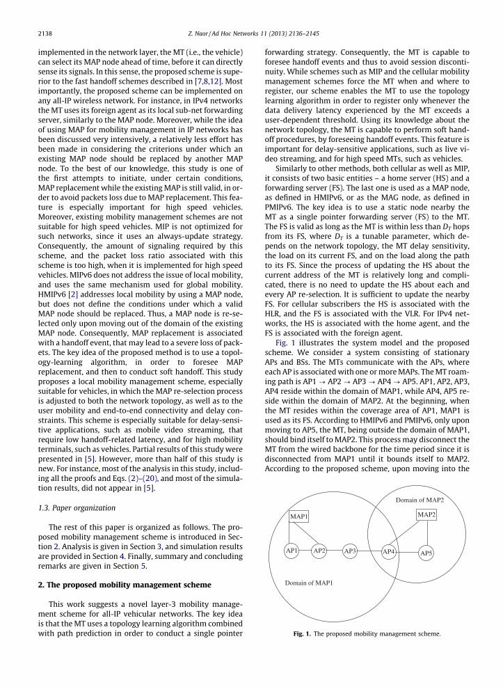
Fig. 1 illustrates the system model and the proposedscheme. We consider a system consisting of stationaryAPs and BSs. The MTs communicate with the APs, whereeach AP is associated with one or more MAPs. The MT roam-ing path is AP1 ? AP2 ? AP3 ? AP4 ? AP5. AP1, AP2, AP3,AP4 reside within the domain of MAP1, while AP4, AP5 re-side within the domain of MAP2. At the beginning, whenthe MT resides within the coverage area of AP1, MAP1 isused as its FS. According to HMIPv6 and PMIPv6, only uponmoving to AP5, the MT, being outside the domain of MAP1,should bind itself to MAP2. This process may disconnect theMT from the wired backbone for the time period since it isdisconnected from MAP1 until it bounds itself to MAP2.According to the proposed scheme, upon moving into the
Z. Naor / Ad Hoc Networks 11 (2013) 2136–2145 2139
coverage area of AP4, the MT uses its knowledge on thenetwork topology and its mobility pattern and registers toMAP2, which becomes its new FS. This soft handoff processshould reduce the packet loss ratio caused by replacing theMAP node, while keeping the latency of packets deliveredto the MT minimal. The decision when to change the FS de-pends on both the network topology, as well as on the MTmobility pattern and delay constraint. Moreover, since thecrucial parameter for FS re-selection is the delay experi-enced by the MT, the maximum number of hops betweenthe MT and its FS is a tunable parameter, which dependson the congestion on the links connecting the MT to itsFS, and on the MT delay constraint.
2.1. The topology learning algorithm
The goal of the topology learning algorithm is to com-pute the distance from the MT to its FS. There is no needfor the MT to be aware to the entire network topology.While roaming across the WAN, the MT learns the networktopology from the APs along its roaming path. Using thefact that each AP must be aware to its nearest neighbors,the knowledge of each AP along its roaming path is mergedinto the MT knowledge about the WAN topology. Below isa detailed description of this learning mechanism.
Definition 1. The connectivity graph G of a WAN is anundirected graph in which each vertex represents a node inthe WAN – either an AP or a BS, and an edge exists betweentwo vertexes if, and only if, the nodes associated with thesetwo vertexes can communicate directly one to each other,without using a third node.
Definition 2. The distance between two vertexes m1 andm2 in the connectivity graph, denoted by d(m1,m2), isdefined as the shortest path, in terms of number of edges,which connects m1 to m2. m2 is called a nearest neighborof m1 if d(m1,m2) = 1. For every vertex m, we defined(m,m) = 0.
The physical meaning of the distance between m1 andm2 is the minimum number of hops required to deliver amessage from m1 to m2. Two nodes m1 and m2 are callednearest neighbors if there is an edge on the connectivitygraph which connects m1 to m2.
Definition 3. The vicinity of a vertex m, denoted by Vm, isdefined as a sub-graph of the connectivity graph G, whichincludes the list of all the vertexes, both APs as well as BSs,that m is aware of. For each vertex v within its vicinity, mholds the IP address of v, its distance from m, and its type –either an AP or a BS.
Definition 4. The vicinity radius of a vertex m is defined asthe positive integer number r that satisfies the conditionsthat each vertex n that its distance from m is less than orequal to r (i.e., d(m,n) 6 r) must be in the vicinity of m,and the distance of each vertex n within the vicinity of mis not larger than r. That is, n 2 Vm M d(m,n) 6 r.
Since each AP must be aware to all its nearest neighbors,for every AP its vicinity radius must be greater than or equalto 1. However, since a multi-hop WAN is not necessarily
regular, some APs may be aware also to their neighbors ata distance of 2 hops and above. For instance, within acrowded urban area, both APs and BSs may be geographi-cally very close to each other. On the other hand, for ruralareas it is likely to have a vicinity radius equals 1. The hopdegree of a vertex m is defined as the vicinity radius of m.
The topology discovery algorithm performed by the MTis based on retrieving the vicinity of each AP along itsroaming path. By merging these vicinities into one graph,the MT can construct its own mobility graph, from whichthe MT can obtain the distance between any pair of nodesalong its roaming path. This information (i.e., the vicinity)can be either advertised periodically, or retrieved by aquery initiated by the MT. However, the vicinity of eachnode, say m, describes only the list of its neighbors, andtheir distance from m. Given that m1, m2 are nodes withinthe vicinity of m, in order to find out d(m1,m2) a learningmechanism must be used. For this reason, the MT mustuse the vicinity of more than one node.
Let m1, m2 be two vertexes in G. Then, the followingtheorem holds:
Theorem 2.1. A necessary and sufficient condition underwhich d(m1,m2) > r1 + r2 is that V1 \ V2 = ;.
Where V1, V2 are the vicinity of m1, m2, respectively,and r1, r2 are the vicinity radius of m1, m2, respectively.
Proof. Given that V1 \ V2 = ;, then we must haved(m1,m2) > r1 + r2. Otherwise, we consider the shortestpath from m1 to m2. If d(m1,m2) 6 r1 + r2 we must have foreach vertex x on this shortest path: d(m1,m2) =d(m1,x) + d(x,m2) 6 r1 + r2. Therefore we must have on thisshortest path at least one vertex x for which d(m1,x) 6 r1and d(x,m2) 6 r2. Thus, x 2 V1 \ V2, in contradiction to thefact that V1 \ V2 = ;. Therefore, we must haved(m1,m2) > r1 + r2. On the other direction, given thatd(m1,m2) > r1 + r2, we get that V1 \ V2 = ;. Otherwise, wemust have at least one vertex, say x, for which we have thatd(m1,x) 6 r1 and d(x,m2) 6 r2. Using the triangularinequality we get that d(m1,m2) 6 d(x,m1) + d(x, m2) 6r1 + r2, in contradiction to the fact that d(m1,m2) > r1 + r2.Thus, we must have V1 \ V2 = ;. h
Theorem 2.2. Given that an MT u knows the vicinity of twovertexes m1, m2, a sufficient condition under which u canaccurately compute the value of d(m1,m2) is that:
dðm1;m2Þ 6 r1þ r2; ð1Þ
where r1, r2 are the vicinity radius of m1, m2, respectively.
Proof. Let V1 and V2 be the vicinity of m1, m2, respectively.That is, V1,V2 are the lists of all the vertexes known to m1,m2, respectively, and their distance from m1, m2, respec-tively. Since d(m1,m2)6 r1 + r2, it follows from Theorem2.1 that V1 \ V2 – ;. In order to compute d(m1,m2),u canuse the triangular inequality for each vertexx, such thatx 2 V1 \ V2: d(m1,m2) 6 d(m1,x) + d(x,m2). Let x be a vertexwhich belongs to the shortest path connecting m1 to m2. Weselect x such that both conditions exist: (A) d(m1,x)6 r1, and
2140 Z. Naor / Ad Hoc Networks 11 (2013) 2136–2145
(B) d(x,m2)6 r2. We must have at least one vertex x that sat-isfies both conditions, since V1 \ V2 – ;. For this vertex x wemust have d(m1,m2) = d(m1,x) + d(x,m2). Thus, in order tocompute d(m1,m2) the MT u just needs to compute, for everyvertex x, x 2 V1 \ V2 the value of d(m1,x) + d(x,m2). The min-imum of this value over all the vertexes within V1 \ V2 yieldsthe correct value of d(m1,m2). h
We define the diameter D of a WAN as the longest dis-tance, in terms of number of edges, between any pair ofvertexes in G. Then, the following Theorem holds:
Theorem 2.3. Given that an MT knows the vicinity of twovertexes, say m1, m2, a sufficient condition under which theMT can accurately compute the distance d(m1,m2) is thatr1 + r2 P D.
Where r1, r2 are the vicinity radius of m1, m2, respec-tively, and D is the diameter of the WAN.
Proof. Let us consider the shortest path between m1 andm2. Since d(m1,m2) 6 D 6 r1 + r2, it follows from Theorem2.1 that we must have at least one vertex, say x, along thispath which satisfies the conditions that d(m1,x) 6 r1, andd(x,m2) 6 r2. The reason for this is that since x is along theshortest path between m1 and m2, given that r1 + r2 P Dwe must have: d(m1,x) + d(x,m2) = d(m1,m2) 6 D 6 r1 +r2. Therefore, it follows from Theorem 2.2, that the MTcan accurately compute the distance d(m1,m2). The dis-tance computation method is similar to the methoddescribed in the proof of Theorem 2.2. h
It follows from Theorem 2.3 that a sufficient condition toaccurately compute d(m1,m2) based only on the vicinity ofm1 and m2, for any pair of vertexes in G, is that for everyAP we have that its vicinity radius r satisfies the conditionr P bD/2c. This condition may look impractical at a firstsight. However, in reality an MT roaming across a WAN isaware to most APs along its roaming path. Thus, the topologylearning algorithm presented above should work in practice.
The topology discovery algorithm enables the MT tomaintain its network connectivity, while keeping the la-tency of message delivery below a pre-defined bound. Inorder to maintain connectivity, the MT selects a static nodethat can be used as a MAP node to be used as its FS, in asimilar manner to the usage of a foreign agent. As long asthe MT remains within the vicinity of its FS, its connectivityto the network backbone is maintained. However, whiledelay-tolerant MTs may prefer a weak connectivity, inorder to reduce their registration rate, delay-sensitiveMTs may prefer to switch their FS more frequently. Thecondition under which the MT can compute the distance,in terms of number of hops, between any pair of APs acrossits path, is given in the next Theorem.
Theorem 2.4. Let m1, m2 be vertexes in G having a vicinityradius of r1, r2, respectively. A sufficient condition underwhich d(m1,m2) can be computed accurately, is that thereexists a simple path (with no cycles in) connecting m1 and m2,for which each vertex x along this path satisfies the conditionx 2 Gu, where Gu is the subgraph of G obtained by merging thevicinity of each AP known to the MT u, and that there is nocycle in G larger than 2(r1 + r2) + 2 that connects m1 and m2.
Proof. Let P denotes the path for which each vertex x alongthis path satisfies the condition x 2 Gu. If d(m1,m2) 6 r1 + r2then it follows from Theorem 2.2 that d(m1,m2) can beobtained just from comparing the vicinity of m1 to that ofm2. Thus, we must have that d(m1,m2) P r1 + r2 + 1. IfP = d(m1,m2) then the shortest path on the subgraphobtained by merging the vicinity of each vertex along Pyields the accurate value of d(m1,m2). Using this estimatedevaluation of d(m1,m2) would not be accurate if, and only if,there exist another path between m1 and m2, which doesnot include any of the vertexes along P, which is shorter thanP. We get therefore that l(P) > d(m1,m2), where l(P) is thelength of P. Thus, l(P) > d(m1,m2) > r1 + r2. Hence, m1 andm2 must be on a cycle, whose length L is given by:L = l(p) + d(m1,m2) P 2d(m1,m2) + 1 P 2(r1 + r2+ 1) + 1 = 2(r1 + r2) + 3. h
It follows from Theorem 2.4 that an MT can compute itsdistance to its FS even outside its vicinity. An MT roamingacross a WAN can always determine the distance betweenany pair of nodes along its path, as long as this distance isless than or equal to 2rmin, where rmin is the minimal hopdegree in the WAN. Even for a larger distance, that isd > 2rmin, the topology discovery algorithm yields an accu-rate distance computation, unless there exist a cycle in theWAN having a length greater than 4rmin + 2. Even under theworst case scenario, for which rmin = 1, an MT can alwaysconduct a topology-independent mobility managementscheme under which the MT is within at most two hopsfrom its FS. Such a strategy guarantees a relatively low rateof updating the home agent, as well as a low upper boundon the latency of data delivery to the MT.
2.2. The proposed mobility management scheme – a formaldescription
The proposed mobility management scheme is asfollows:
1. Initialization: whenever the MT is associated with anew AP, the MT gets the vicinity of this AP.
2. While roaming across the network, the MT queriesabout the vicinity of each AP along its path.
3. Using Theorems 2.2, 2.3, and 2.4, the MT derives theconnectivity graph which describes the connectivitybetween any two APs along its path. Using this informa-tion, the MT obtains its distance from its FS.
4. Whenever the distance from its FS exceeds a pre-defined threshold, the MT selects its new FS, which isthe closest FS, that its distance from the MT decreasesalong its path.
The proposed binding update scheme consists of thefollowing steps:
1. The MT learns the network topology by querying itsnearest neighbors about the APs at their neighbor-hood and their distances. Each AP broadcasts itsidentity. The nearest neighbors of the AP receive this
Z. Naor / Ad Hoc Networks 11 (2013) 2136–2145 2141
message. Their distance from the AP is 1-hop. Theirneighbors that are not neighbors of the AP are at adistance 2-hops from the AP and so on.
2. Whenever the MT identifies entering to the servicearea of a new AP, this AP becomes its local server(LS), and the MT transmits a registration messageto the nearby AP, and informs its new LS the ID ofits previous server and FS.
3. The registration message is forwarded to the previ-ous LS.
4. The new LS updates its associated database, indicat-ing that the MT is now residing in its service area.
5. The new LS sends a registration cancelation messageto the previous LS, to inform the previous LS that theMT is now residing in its service area.
6. Upon receiving the registration cancelation message,the previous LS removes the user record from itsassociated database, and sends a cancelationacknowledgment message to the new LS. If the pre-vious LS is also the FS, it updates its pointer to pointto the new LS.
7. Upon receiving the cancelation acknowledgmentmessage, the new LS compares the ID of the previousLS with the ID of the FS. If they are different, and thedistance between the new LS and the FS, in terms ofnumber of hops, is less than a pre-defined distancethreshold DT – a binding update message is sent fromthe new LS to the FS, that informs the FS that the MThas moved to a new AP, and continue to the next step.If the distance between the new LS and the FS isgreater or equal to DT – a binding update message issent to the HS. In this case, go to step 9.
8. Upon receiving the binding update message, the FSupdates its pointer to point to the new LS and sendsa binding update acknowledge to the new LS. Thebinding update procedure is complete, do not con-tinue to the next step.
9. The new LS sends a binding update message to the HS,to inform that the MT is now residing in its servicearea. Upon receiving the binding update message, theHS modifies its pointer to point to the new LS, andsends a registration acknowledge message to thenew LS. If the distance between the HS and the newLS, in terms of number of hops, is greater than 2DT, thenthe new LS is from now on the new FS. If the distancebetween the HS and the new LS is less than or equalto 2DT, the HS does not use forwarding. The registrationacknowledge message sent by the HS to the new LS isused also as a forwarding acknowledge message, thatinforms the new LS which scheme must be used.
10. The HS sends a forwarding cancelation message tothe previous FS.
11. Upon receiving the forwarding cancelation message,the previous FS removes the user record from itsassociated database, and sends a cancelationacknowledgment message to the HS.
3. Analysis
In this section we analyze our mobility managementscheme from different aspects of correctness, robustness,
practicality, and complexity. The first aspect is its correct-ness. It follows from Theorem 2.3 that the MT can alwayscompute the distance between two nodes, say m1, m2,along its roaming path up to a distance of r1 + r2 hops,where r1, r2 are the hop degree of m1, m2, respectively.Since any AP must be aware to the IP address of its nearestneighbors, Theorem 2.3 implies that the MT can alwaysaccurately compute its distance from its FS up to a distanceof at least two hops. Using Theorem 2.1, a mobility manage-ment strategy that updates the MT home agent only whenits distance from its forwarding pointer server (e.g., the for-eign agent in MIP, or the MAP in HMIPv6) is at least 3 hopscan be always achieved, regardless the topology of the WAN.The proof follows directly from Theorem 2.1: At the firsttime that V1 \ V2 = ;, where V1, V2 are the vicinity of m1,m2, respectively, then we must have: d(m1,m2) > r1 +r2 P 2. Whenever the WAN topology is taken into consid-eration, even a higher value of the lower bound on the dis-tance, in terms of number of hops, between the MT and itsforwarding pointer server can be achieved, subject to theconstraints that follow from Theorem 2.4.
The mobility management scheme is robust in the sensethat even if the MT roaming path is not continues, the MTcan still recover the missing information from other APsalong its roaming path. This feature is important, sincedue to phenomenons such as temporary loss of line ofsight, it may happen that the connection between the MTand its associated AP is lost, and the MT next associationis with an AP which is not a nearest neighbor of its previ-ous associated AP. As we show below, for most practicalcases the topology discovery algorithm can recover fromthis situation. To prove that, let us denote the last AP thatits vicinity is known to the MT by m. It follows from Theo-rem 2.2 that even if for some reason the MT is not aware tothe vicinity of any of the nearest neighbors of m, this infor-mation can be recovered from their nearest neighbors, thattheir distance from m is 2, even if the hop degree of everyAP is only one. To prove this observation, we just have tosubstitute r1 = r2 = 1 and d(m1,m2) = 2 in Theorem 2.2, tosee that the condition for accurate distance computationholds. Note that from the definition of the WAN, each APmust have a hop degree of at least one. For instance, letus consider the worst case scenario where the hop degreeequals 1 for every AP. Under this condition, even if theMT roaming path is m1, m2, where d(m1,m2) = 2, theremust be an intermediate node, say t, such that t is a nearestneighbor of both m1 and m2. Comparing the vicinity of m1to the vicinity of m2, the MT can find t, and recover themissing information in its knowledge about the networktopology. Note that as the vicinity of the APs along itsroaming path increases, the MT capability to recover fromsuch scenarios increases too. For instance, using Theorem2.1, if the hop degree is at least 2 for all the APs, the MTmay be disconnected from its associated AP and stillrecover even if its next associated AP is at a distance of 4hops from its previous associated AP.
The complexity of the topology discovery algorithm is asfollows. The process of storing the vicinity of a node has amemory complexity of O(n), where n is the number ofAPs + BSs in the WAN. In order to merge the vicinity of anAP with the MT knowledge about the WAN, each node
2142 Z. Naor / Ad Hoc Networks 11 (2013) 2136–2145
already known to the MT must be compared to the nodeswithin the new vicinity. Thus, the merge process has a worstcase time complexity of O(n2). Since we compute the dis-tance for each AP with at most n neighbors, the worst casememory complexity is O(n2). Since this process is per-formed for each AP along the MT roaming path, the worstcase time complexity of the topology discovery algorithmis O(n3), and the worst case memory complexity is O(n2).
In terms of practicality, the information used for topol-ogy discovery already exists in current WANs, since any APmust be aware to its nearest neighbors. Due to its simplic-ity and low complexity, the proposed mobility manage-ment scheme can be easily applied on MTs. There is noneed for any hardware modification, and there is no needto use any information that is not currently available.Moreover, since the nearby AP which is used as the MTFS is used as its foreign agent in MIPv4, or as its MAP inHMIPv6, the proposed scheme can be applied on any IPWAN network.
4. Performance analysis and simulation results
To compare the performance of the proposed methodwith that of alternative methods, we consider an indepen-dent and identically distributed (i.i.d) motion model. Tomodel the movement of the MTs, it is assumed that timeis slotted, and an MT can make at most one movement toanother AP during one time unit, which can be arbitrarysmall. The movements are assumed to be stochastic andindependent from one MT to another. An MT can moveat each time unit to a neighboring AP with probability P,or remains attached to its current AP with probabilityQ = 1 � P. To further consider the worst situation for theproposed scheme we consider a metropolitan area, inwhich a random walk model can be used as the motionmodel, unlike the highway in which the motion can be eas-ily predicted. The system considered is an infinite twodimensional system with grid topology, using the Manhat-tan metric for distance computation. Therefore, the MT canmove either horizontally or vertically to each one of itsfour nearest neighbors. The distance between two APs ismeasured by the number of hops required to deliver amessage from one AP to the other. It is assumed that eachAP has exactly four nearest neighbors, and the distance iscomputed using the city block metric (known also as Man-hattan metric). That is, the distance is the sum of the hor-izontal and vertical distances.
Since the probability to switch from one AP to anotherduring a time unit is P, the expected number of movementsbetween neighboring APs during t time units is given by
M ¼ tP: ð2Þ
Given that the threshold length of the chain of pointershandled by the LL scheme is k, the length of the chain ofpointers at the arrival time of the call is given by
l ¼ m mod k; ð3Þ
where m is the number of AP movements since the lastsession. Since the delay of the session set up procedure
depends on the time period required to query all the APsalong the chain of pointers, the session set up delay is pro-portional to the length l given in Eq. (3). The expected in-crease in the session set up delay incurred by theproposed method, in comparison with MIP is either zeroor 1, depending on the distance between the MT and itsFS. Hence, given that the length of the time interval be-tween two consecutive sessions is t, the expected increasein the session set up delay is given by
delayðtÞ ¼ 1� P0ðtÞ < 1� ð1� PÞt ; ð4Þ
where P0(t) is the probability that after t time units the dis-tance between the MT and its FS is zero. That is, either theMT has made no movement during t time units, with prob-ability (1 � P)t, or that the MT has traveled a distance ofnDT hops, n = 0, 1, 2 . . . The expected ratio of the sessionset up delay under the LL scheme to the session set up de-lay under the proposed scheme is bounded from below bythe ratio of the length l given in Eq. (3), to the upper boundon the expected delay given in Eq. (4).
The number of HS location update events under the LLscheme is simply the number of times that the length ofthe chain of pointers has exceeded the value of k duringthe time interval between two successive sessions. Hence,it is given by
ULL ¼Psk
� �; ð5Þ
where the parameter s is the length of the time interval be-tween two successive sessions. The number of HS locationupdate events between two successive sessions under theproposed location management scheme depends on thedistance, in terms of number of hops, traveled by the MTduring this time period. According to the two dimensionali.i.d. model used in this study, an MT can move, at eachtime unit, either horizontally to the left or to the right withprobabilities plh and prh respectively, or move vertically tothe right or to the left with probabilities prv and plv, respec-tively. The probability to move either horizontally or verti-cally is given by
Ph ¼ plh þ prh; Pv ¼ plv þ prv : ð6Þ
In order to travel a distance of d hops along one axis, sayto the left, the number of movements to the left must ex-ceed the number of movements to the right by exactly dmovements. Hence, given that the MT has made m move-ments since its last HS location update, the probabilityalh(d,m) to travel a distance of d hops horizontally to theleft is given by
alhðd;mÞ ¼m
m�d2
!p
mþd2
lh pm�d
2rh ; ð7Þ
if m P d P 1 and m � d is even, and 0 otherwise. Similarly,the probability to travel a distance of d hops horizontally tothe right, given that m movements were made since thelast HS location update is given by
arhðd;mÞ ¼m
m�d2
!p
mþd2
rh pm�d
2lh ; ð8Þ
Z. Naor / Ad Hoc Networks 11 (2013) 2136–2145 2143
if m P d P 1 and m � d is even, and 0 otherwise. The prob-ability to travel a distance of dh hops along this axis is theprobability to travel dh hops either to the right or to the left
aðdh;mÞ ¼ arhðdh;mÞ þ alhðdh;mÞ: ð9Þ
Similarly, the probability to travel a distance of dv hopsvertically is given by a(dv,m). Substitute Eqs. (7) and (8) inEq. (9) yields
aðdh;mÞ ¼ pdhrh þ pdh
lh
� � m
x
� �px
rhpxlh; ð10Þ
if m P dh P 1 and m � dh is even, and 0 otherwise, wherex ¼ m�dh
2 . The probability to make m movements during ttime units is given by
bðm; tÞ ¼t
m
� �Pmð1� PÞt�m
; ð11Þ
if m 6 t, and 0 if m > t.The probability of traveling a distance d, given that the
MT has made m movements, is the sum of all probabilitiesof traveling a distance dh along the horizontal axis, and adistance dv along the vertical axis, where dh + dv = d, sub-ject to the condition that the number of movements alongthe horizontal axis is mh, and the number of movementsalong the vertical axis is mv, such that mh + mv = m. Notethat given d, m, dh, mh, it follows that mv = m �mh, and thatdv = d � dh. Hence, given d and m, the pair (mv,dv) is deter-mined by the pair (mh,dh) and the constraint thatmh + mv = m P d = dh + dv. The probability of traveling adistance d, given that the MT has made m movements, fromwhich mh movements along the horizontal axis, and giventhat the MT has traveled a distance dh along the horizontalaxis, is given by:
sðd;m; dh;mhÞ ¼ 4mh
mh�dh2
!m�mh
ðm�mhÞ�ðd�dhÞ2 :
!ð12Þ
For mh � dh even, m � d even, and d > dh > 0. For mh � dh
even, m � d even, where dh equals either zero or d, it fol-lows that:
sðd;m; dh;mhÞ ¼ 2mh
mh�dh2
!m�mh
ðm�mhÞ�ðd�dhÞ2 :
!ð13Þ
For any other case s(d,m,dh, mh) = 0. The probability oftraveling a distance d, given that the MT has made m move-ments, is the sum over all possible values of mh that satisfythe constraints mentioned above:
Sðd;mÞ ¼Xd
dh¼0
Xm
mh¼dh
sðd;m; dh;mhÞ ð14Þ
Using the constraints dh 6mh 6m, dh 6 d, andd � dh = dv 6mv = m �mh, it follows that:
dh ¼ d� dv P d�mv ¼ d� ðm�mhÞ: ð15Þ
Hence, it follows from Eq. (14) and (15) that:
Sðd;mÞ ¼ 14m
Xm
mh¼0
m
mh
� � Xminfmh ;dg
dh¼maxf0;d�ðm�mhÞgsðd;m;dh;mhÞ:
ð16Þ
The probability of traveling a distance of d hops duringexactly t time units is the sum over all probabilities S(d,m),where m ranges from d to t:
cðd; tÞ ¼Xt
m¼d
Sðd;mÞbðm; tÞ: ð17Þ
Hence, given that the time interval between two consecu-tive sessions is s time units, the expected number of HSlocation update events during this time period is given by
UðDT ; sÞ ¼Xs
d¼DT
cðd; sÞ dDT
� �: ð18Þ
The explanation of Eq. (18) is as follows: given that theMT has traveled a distance of d hops, the number of HSlocation update events during the traveling time is
dðd;DTÞ ¼d
DT
� �: ð19Þ
Using the fact that c(d,t) = 0 if d > t, we get that the ex-pected number of HS location update events during timeinterval of s time units is the sum over all possibilities totravel a distance of d hops during s time units, multipliedby d
DT
j k, where d ranges from d = DT to d = s. Substitute
Eq. (17) in Eq. (18) we get that
UðDT ; sÞ ¼Xs
d¼DT
Xs
m¼d
Sðd;mÞbðm; sÞ dDT
� �; ð20Þ
if DT 6 s, and 0 if DT > s.
4.1. Simulation results
In this section we use simulation to compare the perfor-mance of the proposed scheme with the performance ofMIPv6, PMIPv6, and the linked-list (LL) scheme [1,4,11,6].Note that HMIPv6 [2] is not considered, since the proposedmethod fits into HMIPv6, and the main difference betweenthe proposed method and [2] is expressed in the MAPreplacement criterion. The system considered is based ontwo dimensional grid topology, as described previously inthis section. Each tile has dimensions of 250 � 250 m.The performance metrics are the packet loss ratio, messagedelivery delay, and the number of binding update events.
Fig. 2 depicts the packet loss ratio caused by handoff, gi-ven in percentage, for MIPv6, PMIPv6, the linked-list (LL)scheme [1,4,11,6], and the proposed scheme. The packetloss ratio is depicted as a function of the mobility to ses-sion ratio l, defined as the expected number of BSs associ-ated with the MT between two consecutive sessions. TheMT under consideration is a delay-sensitive terminal(e.g., during video session). Therefore, upon moving awayfrom its MAP for three hops and above, though yet withinthe MAP domain, the MT must bind itself to a closer MAP.For this reason, both PMIPv6 and the LL scheme suffer froma significant loss of packets. On the other hand, using theMIP scheme, the MT must perform frequent binding up-date tasks caused by handoff events, that lead to a signifi-cant loss of packets. The proposed method demonstratesthe best performance among these methods. For lowmobility users the packet loss ratio caused by handoff
0 2 4 6 8 100
2
4
6
8
10
12
14
16
18
20
Mobility to Session Ratio µ
Pack
et L
oss
Rat
io (p
erce
ntag
e)−: proposed method*: MIPv6 o: LL method
x: PMIPv6
Fig. 2. The packet loss ratio caused by handoff, given in percentage, forMIPv6, PMIPv6, the LL scheme, and the proposed method, as a function ofthe mobility to session ratio l, for delay-sensitive MT.
2144 Z. Naor / Ad Hoc Networks 11 (2013) 2136–2145
ranges from 1% to 2% for all the schemes under consider-ation (though the proposed scheme shows the best perfor-mance). However, the superiority of the proposed methodincreases with the mobility to session ratio, and for highmobility users (e.g., high speed vehicles) the packet loss ra-tio expected for the proposed method is three times betterthan MIPv6 (5% packet loss ratio versus 15%).
Fig. 3 depicts the expected delay for message deliveryfor MIPv6, the LL scheme, and the proposed method. Theexpected delay, measured by the number of hops, is de-picted as a function of the mobility to session ratio l, fora distance threshold DT = 2. Note that as the length of thelinked list used by the LL scheme exceeds its maximumlength, an HS location update occurs. Therefore the tempo-rary reduction in the packet delivery latency depicted inFig. 3 is expected from the LL scheme for high mobilityMTs. This temporary reduction is achieved at the cost ofincreasing the HS location update rate. It is clearly shown
0 2 4 6 8 100
1
2
3
4
5
6
7
8
9
10
Mobility to Sesion Ratio µ
Expe
cted
pac
ket d
eliv
ery
dela
y *: MIPv6
o: LL method
−: proposed method
Fig. 3. The expected latency for message delivery, in terms of number ofhops, for MIPv6 that does not use HMIPv6, the LL scheme, and theproposed method, as a function of the mobility to session ratio l.
that the expected delay produced by both MIPv6 (that doesnot use HMIPv6) and the LL method is significantly largerthan the equivalent delay expected from the proposedmethod. The superiority of the proposed method increaseswith l.
Fig. 4 depicts the ratio of the expected delay (measuredby the number of hops) for message delivery for the LLscheme to the expected delay for the proposed method,as a function of the length of the time interval betweentwo successive sessions, measured in minutes, for twocases of vehicle velocity, of 10 mph and 20 mph. A distancethreshold of DT = 3 was used by the proposed method, anda chain length threshold of k = 5, above which the LL meth-od should update the HS, was used. As expected, the delayfor message delivery expected for the LL method is signif-icantly larger than the equivalent delay expected for theproposed method. The delay ratio, defined as the numberof hops required for message delivery expected for the LLscheme, divided by the equivalent number expected forthe proposed method, increases with mobility, and withthe length of the time interval between two successive ses-sions. For the extreme case of high mobility user and timeinterval of 60 min between two successive sessions, thedelay for message delivery expected for the LL method is10 times larger than the equivalent delay expected forthe proposed method.
Fig. 5 depicts the expected number of binding updateevents for the linked list method, MIP, and the proposedmethod, as a function of the mobility to session ratio l,for directional mobility pattern, that is plh = 3prh, Pv = 0,and P = 0.3 (see Eq. (6)). The proposed method has the bestperformance, while MIP has the worst performance. Aspredicted by Eq. (20), the superiority of the proposedmethod increases with mobility. The simulation resultsverify the number of binding update events expected fromEq. (20). At the extreme case of high mobility to session ra-tio, the number of binding events expected for MIP is about20 times larger than the equivalent number expected forthe proposed method. Thus, for high speed vehicles the
0 10 20 30 40 500
1
2
3
4
5
6
7
8
9
10
Time
Del
ay R
atio
x: V = 20mpho: V = 10mph
Fig. 4. The ratio of the expected delay for message delivery for the linkedlist method to the expected delay for message delivery for the proposedmethod, as a function of the length of the time interval between twosuccessive sessions.
Fig. 5. The expected number of binding update events for the linked listmethod, MIP, and the proposed method, as a function of the mobility tosession ratio l, for directional mobility pattern, high mobility MTs.
Z. Naor / Ad Hoc Networks 11 (2013) 2136–2145 2145
performance of the proposed method is significantly muchbetter than the performance of all the other methods.
5. Summary and concluding remarks
The method proposed in this study is particularly suit-able for vehicular networks. However, it can be easily ap-plied for any all-IP wireless network. It offers fast andreliable handoff and a reduced delay for message delivery,as well as a reduced rate of HS location update, in compar-ison with MIP, MIPv6, and the LL method [1,4,11,6]. Theconcept of using a MAP node can be easily used to inte-grate a vehicular network with both cellular networks aswell as an all-IP network, and fits into HMIPv6. The pro-posed scheme does not make pre-assumptions, neitherabout the vehicle mobility pattern, nor about the networktopology. An important feature of the proposed scheme isthat it can be easily implemented, even on IPv4 networks.
References
[1] C. Chu, C. Weng, Pointer forwarding MIPv6 mobility management,in: Proc. IEEE GLOBCOM 2002, December 2002.
[2] H. Soliman, C. Castelluccia, K.E. Malki, L. Bellier, Hierarchical mobileIPv6 mobility management (HMIPv6), IETF RFC 4140, August 2005.
[3] K. Kawano et al., A mobility-based terminal management in IPv6networks, IEICE Trans. Commun. E85-B (10) (2002).
[4] W. Ma, Y. Fang, Dynamic hierarchical mobility management strategyfor mobile IP networks, IEEE J. Selected Areas Commun. 22 (4)(2004).
[5] Z. Naor, Mobility management for wireless metropolitan areanetworks, in: IEEE Sarnoff Symposium 2010, April 2010, Princeton,NJ, USA.
[6] S. Pack, B. Lee, T. Kwon, Y. Choi, A pointer forwarding scheme withmobility-aware binding update in mobile IPv6 networks, ComputCommun 31 (5) (2008).
[7] S. Pack, Y. Choi, Fast handoff scheme based on mobility prediction inpublic wireless LAN systems, Proc. IEE Commun. 151 (2004) 489–495.
[8] S. Pack, H. Jung, T. Kwon, Y. Choi, A Selective neighbor cachingscheme for fast handoff in IEEE 802.11 wireless networks, Proc. ofIEEE ICC (2005).
[9] H. Soliman, Hierarchical Mobile IPv6 Mobility Management(HMIPv6), Internet Draft, 2003.
[10] Y. Xu et al., A Local Mobility Agent Selection Algorithm for MobileNetworks, Proc. IEEE ICC (2003).
[11] M. Yi, C. Hwang, A pointer forwarding for minimizing signing cost inhierarchical mobile IPv6 networks, in: Proc. EUC 2004, 2004.
[12] I. Ramani, S. Savage, SyncScan: practical fast handoff for 802.11infrastructure networks, Proc. IEEE INFOCOM (2005) 675–684.
[13] S. Gundavelli, K. Leung, V. Devarapalli, K. Chowdhury, B. Patil, ProxyMobile IPv6, RFC 5213, August 2008.
[14] Yuh-Shyan Chen, Ching-Hsueh Cheng, Chih-Shun Hsu, Ge-MingChiu, Network mobility protocol for vehicular ad hoc networks, in:IEEE Wireless Communications and Networking Conference (WCNC2009), Budapest, Hungary, 5–8 April, 2009.
Zohar Naor received the PhD degree inComputer Science from Tel Aviv University,Tel Aviv, Israel, in 2000. Since 2003 he is withthe University of Haifa, Israel. His areas ofinterests include wireless networks, resourcemanagement of computer networks, mobilitymanagement, search strategies, and multipleaccess protocols.