TECHNICAL INFORMATION AND START-UP Translation of the original German operating instructions On-board Fast Charger NLG664-U0 BRUSA Elektronik AG Neudorf 14 CH-9466 Sennwald +41 81 758 19 00 www.brusa.biz [email protected]
Transcript
TECHNICAL INFORMATION AND START-UP
Translation of the original German operating instructions
On-board Fast Charger NLG664-U0
BRUSA Elektronik AG Neudorf 14 CH-9466 Sennwald +41 81 758 19 00 www.brusa.biz [email protected]
Technical information and start-up
Fast Charger NLG6xx
2
LEGAL NOTICE
Publisher BRUSA Elektronik AG Neudorf 14 CH–9466 Sennwald T +41 81 758 19 - 00 F +41 81 758 19 - 99 www.brusa.biz [email protected]
Updates In light of the further technical development of our products, we reserve the right to make constructional changes. Any changes will be made known in the relevant manuals through the replacement of the relevant pages and/or a revision of the electronic data storage device.
13 Index ....................................................................................................................................... 64
Technical information and start-up Fast Charger NLG6xx
7
1 Foreword
Dear Customer!
With the BRUSA NLG6 charger, you have purchased a versatile high-performance product. The device is a power electronics product which uses dangerous voltages and currents, thus special expertise with respect to handling and operation of such systems is required!
Read this manual – particularly the chapter Safety and warning instructions – carefully before you install the Fast Charger NLG6xx or carry out any other work on it!
1.1 General characteristics
INFORMATION
Below there is a short overview of the performance and versatility of the NLG6 charger. You will find details on the individual properties as you read through this manual.
Manufactured and tested according to European automotive standards.
This VDE-certified charger complies with all applicable European legal requirements. EMC compliance is to be achieved in combination with the vehicle.
Galvanic isolation between mains and battery circuit guarantees optimum protection of personnel.
Touch and leakage current values remain within required limits, without further measures.
The charger can be used in connection with a standard type A RCD.
The power factor cos(phi) is nearly =1, therefore the available mains power is used to the maximum.
The charging current contains a very low ripple.
Charging from single or three-phase outlet.
Parallel connection of several chargers is possible, in order to achieve higher charging power.
Highly efficient (typically >94%).
Robust against dust, humidity, vibration etc.
Technical information and start-up
Fast Charger NLG6xx
8
1.2 Labelling information, traceability and documentation of devices and components BRUSA Elektronik AG ensures a complete quality proof for all raw materials, manufacturing
processes and products by means of suitable labelling and traceability measures.
Traceability shall be organised in such a way that in the event of a defect the following characteristics can be identified at any time:
Manufacturer
Production batch
Production line
Original batch
2 List of abbreviations
Throughout this manual, certain specific technical abbreviations are used. The following table provides an overview of these abbreviations and their meaning:
Abk. Bezeichnung Abk. Bezeichnung
BMS BatteryΜanagementSystem LV Low Voltage BTLcycle Time quanta per Bit NBT NLG Netzladegerät (AC charger) CAN Controller Area Network PFC Power Factor Correction CP Contol Pilot PI Power Indicator EME Electromagnetic Emission PLC PowerLine Communication EMI Electromagnetic Interference PRC Power Ripple Compensation EVSE Electric Vehicle Supply Equipment PWM Pulse-Width Modulation GND Ground RTC Real Time Clock HV High Voltage (hazardous voltage) SAE Society of Automotive Engineers IEC International Electrotechnical Commission SJW Synchronization Jump Width LED Light Emitting Diode VCU Vehicle Control Unit
Technical information and start-up Fast Charger NLG6xx
9
3 Safety and warning instructions
In this chapter, you will find safety instructions applying to this device. These instructions refer to the assembly, start-up and the running operation in the vehicle. Always read and observe these instructions in order to protect people's safety and lives and to avoid damage to the device!
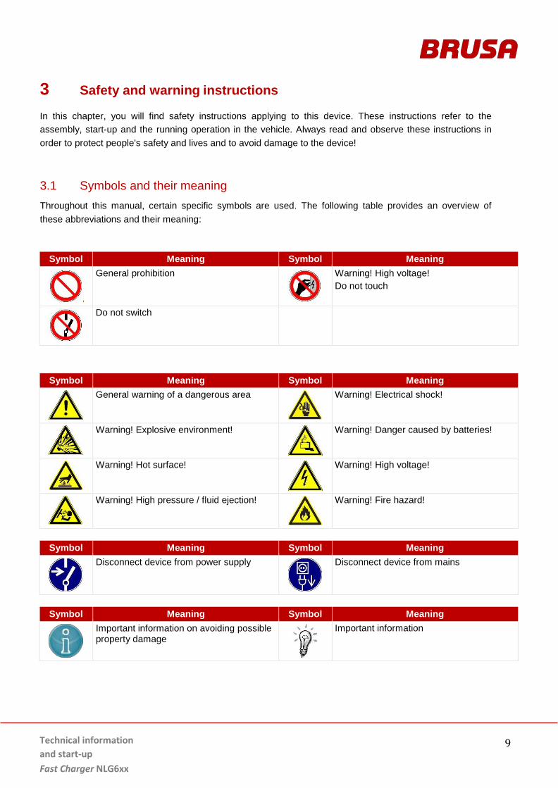
3.1 Symbols and their meaning Throughout this manual, certain specific symbols are used. The following table provides an overview of these abbreviations and their meaning:
Symbol Meaning Symbol Meaning
General prohibition
Warning! High voltage! Do not touch
Do not switch
Symbol Meaning Symbol Meaning
General warning of a dangerous area
Warning! Electrical shock!
Warning! Explosive environment!
Warning! Danger caused by batteries!
Warning! Hot surface!
Warning! High voltage!
Warning! High pressure / fluid ejection!
Warning! Fire hazard!
Symbol Meaning Symbol Meaning
Disconnect device from power supply
Disconnect device from mains
Symbol Meaning Symbol Meaning
Important information on avoiding possible property damage
Important information
Technical information and start-up
Fast Charger NLG6xx
10
3.2 Safety instructions and danger levels
DANGER This instruction warns about severe irreversible risks of personal injury with possibly fatal consequences. Avoid this risk by adhering to these instructions!
CAUTION This instruction warns about a minor risk of injury! Avoid this risk by adhering to these instructions!
INSTRUCTION
This instruction warns against possible damages to property if the following instructions and work procedures are not observed.
INFORMATION
This type of instruction makes important information known to the reader.
WARNING This instruction warns about the risk of severe but reversible injury! Avoid this risk by adhering to these instructions!
Technical information and start-up Fast Charger NLG6xx
11
3.3 Generally applicable safety measures The following safety measures have been developed based on the knowledge of the manufacturer. They are incomplete as they can be supplemented by local and/or country-specific safety instructions and guidelines for accident prevention.
The system integrator and/or distributor of the device must therefore supplement the present general safety instructions with country-specific and local guidelines.
3.3.1 Safety instructions for cooling water systems
WARNING Cooling fluid ejection! Danger of burns! Check the water tightness of the cooling water system, particularly the pipes, screw joints and
pressure tanks!
Repair any identifiable leaks immediately!
Ensure at all times that the maximum permissible pressure in the cooling system is not exceeded (e.g. by installation of pressure compensation valves)!
Ensure at all times that the maximum permissible cooling water temperature is not exceeded!
3.3.2 Safety instructions for mechanical systems
DANGER Explosive environment! Danger to life! Do not store any highly flammable substances or combustible fluids in the direct surroundings of
the device! Sparks forming at the device's connections can set these on fire and lead to explosions!
CAUTION
Hot surfaces! Burn hazard! The device produces high temperatures when in operation! Therefore, the device is to be
handled with care and caution at all times!
Technical information and start-up
Fast Charger NLG6xx
12
3.3.3 Safety instructions for handling and operation
INSTRUCTION Damage to HV battery: Make sure that the voltage range of the device complies with the voltage range of the HV battery!
Only use technically suitable and high-quality cables! Should you have any further questions, please contact BRUSA Elektronik AG under the manufacturer address mentioned in chapter 4.6.
INSTRUCTION
Damage to the charger: When connecting the device, always ensure that the mains voltage is within the permissible
range (refer to chapter 6.1 Technical data)!
A high cooling water temperature and/or ambient temperature reduces the life span! Therefore, ensure that the device is continuously cooled sufficiently!
Do not install the device in direct sunlight and in direct proximity to heat sources!
Even though the device has a high IP protection class, direct contact with water (rain, splashing water) and dirt should be avoided.
Under no circumstances should you put a low-resistance connection between the HV contacts, the housing contacts and the LV contacts! This will lead to malfunctions and in time to the destruction of the device!
Prevent any penetration of fluids into the device (e.g. during assembly work)! Fluid ingress will lead to a short circuit and subsequently to damage to the device!
In the case of any fluid ingression, do not start the device and immediately contact BRUSA Elektronik AG.
The tightness of the battery charger can only be guaranteed if all the signal cable to the signal connectors are packaged and connected to a tight unit. If this is not the case in one of the cables, it must be separately sealed.
Technical information and start-up Fast Charger NLG6xx
13
3.3.4 Safety instructions for electrical systems
DANGER High voltage! Danger to life! Never touch the HV wires or HV connections without ensuring the absence of voltage
beforehand!
The device may only be connected by a qualified electrician! Refer to chapter 3.5 Requirements on the start-up personnel
Safety installations must never be by-passed or circumvented! Any resulting malfunctions could have life threatening consequences!
Never connect the device to a socket without a protective earth conductor!
Always apply a residual current device (RCD) to the mains connection!
CAUTION
Damage to the cable! Fire hazard! If a cable drum is used as an extension cord to the mains connection, it might ignite due to heat
accumulation! Therefore, always unwind the cable drum completely!
INSTRUCTION
The device is never to be opened! The opening of the device (sealed housing) directly leads to the forfeiture of any liability by BRUSA Elektronik AG! Refer to chapter 11 Liability
INFORMATION
When working on a HV system, the following 5 safety rules have to be strictly adhered to: Disconnect system from power. Switch off the ignition. Remove service / maintenance plug and/or turn off main battery switch Remove fuse
Ensure that the system cannot be reactivated. Keep ignition key safe to prevent unauthorised access. Keep the service / maintenance plug safe in order to prevent unauthorised access and/or
use lockable cover cap to ensure that the main battery switch is not reactivated.
Ensure that the device is de-energised by using a suitable voltage tester (pay attention to the voltage range!)
Earth and short-circuit the system.
Cover or isolate adjacent live parts.
Technical information and start-up
Fast Charger NLG6xx
14
3.4 Safety installations / power limitations
3.4.1 Control Pilot acc. to SAEJ1772 and / or IEC61851
Control-Pilot (CP) is a standardised signal transmitted via an additional conductor in the charging plug. The CP interface enables a bidirectional exchange of information between the charging station and electric vehicle and is globally standardised. Thanks to this signal, the EVSE can provide the charger with information on the permissible maximum current load of the mains socket and the available power capacity. In case of the NLG6, this current can be max 32 A (= max. current limited by the charger). The charging process is coordinated via this signal and appropriate grounding is ensured.
The Control Pilot is a safety measure that also increases the reliability of the charging process of an electric vehicle. It is absolutely necessary if the charging current on the mains side exceeds 16 A.
3.4.2 Mains overvoltage protection
Overvoltage protection is integrated in the charger to provide permanent protection against overloading. Mains overvoltage is detected by the quick sensor system and leads to immediate shut down of the charger. Highly energetic overvoltage (e.g. due to lightning) is absorbed by protective elements.
Also on the output side, overvoltage protection is integrated. The quick sensor system detects overvoltage on the HV battery side (e.g. load drop or fluctuations) and the charger is immediately shut down.
3.4.3 Mains protection input current
On the charger, each phase (L1, L2, L3, N) is protected by a 40 A fuse in order to protect the device and electric systems from damage due to overcurrent. If one of these fuses is blown, the charger must be returned to BRUSA Elektronik AG! Do not open the device – no user serviceable parts inside.
3.4.4 Overcurrent protection
Overcurrent protection is integrated in the charger to avoid overload damage. The quick sensor system detects any overcurrent and either reduces the current by regulation or shuts the charger down.
INSTRUCTION
We strongly recommended that you install a suitable overcurrent protection (fuse) close to the battery between charger and battery, in order to protect the wires between charger and battery!
Technical information and start-up Fast Charger NLG6xx
15
3.4.5 Overtemperature protection (derating)
INSTRUCTION Continuous operation at the temperature limit will inevitably lead to a higher level of wear of the components!
The charger protects itself through temperature dependent derating. If the charger reaches a defined temperature limit, it reduces the power (derating) to protect the charger from damage due to overheating. The power is reduced according to the temperature increase in order to keep the temperature within the target range. The charging process is not interrupted though, but continues seamlessly without reduced power. If the temperature of the coolant exceeds +65 °C, we recommend to shut down the charger to prevent damage. We recommend not to exceed a maximum coolant temperature of +55 °C.
In total, the NLG6 charger is equipped with 10 temperature sensors in different areas. Depending on the operation situation, activation time and temperature of the derating may thus vary.
Technical information and start-up
Fast Charger NLG6xx
16
3.4.6 HV Interlock acc. to LV123
The interlock is a protective loop in the vehicle which monitors the drive components. It also allows monitoring of HV side plug connections at the charger. Wiring of the interlock pins does not influence the functionality of the charger, but in order to ensure safety, we strongly recommend that an interlock system is employed! These interlock pins can carry +/-48VDC nominal to Gnd, at 10mA (max. 20mA).
Technical information and start-up Fast Charger NLG6xx
17
3.4.7 Proximity Detection acc. to IEC 61851
Proximity defines an additional resistor attached to the connector of the charging cord, which indicates the maximum ampacity of the cord. This resistor is measured by the charger and defines the amount of current that the cord is allowed to conduct. This resistor is standardised and therefore independent of the manufacturer. Due to Proximity Detection the charger can detect:
Whether a charging cable is connected to the vehicle
Which cable type is connected
Which amperage is possible with the charging cable (range of 6 -
63 A) The NLG6 charger generally limits the possible charging current
to max. 32 A.
INFORMATION For this function, a 4.7 kΩ resistor must be integrated in the Charge Coupler! This must be provided by the customer (refer to drawing).
3.4.8 Active discharge
The device features active discharge of circuits. As soon as the device is disconnected from the HV, the internal HV circuits discharge:
at applied HV voltage 320 V = < 2.4 s to < 30 V
at applied HV voltage 420 V = < 4.7 s to < 30 V
Technical information and start-up
Fast Charger NLG6xx
18
3.5 Requirements on the start-up personnel All courses of action described in this manual may only be carried out by a qualified electrician! Specialist staff are defined as electricians who have had
specific professional training,
have knowledge and experience in the field of electronics / electric mobility,
as well as knowledge of relevant provisions and dangers
for which they can provide proof. Furthermore, they must be able to assess the work assigned to them independently, identify possible dangers and establish necessary protection measures.
Technical information and start-up Fast Charger NLG6xx
19
4 General
4.1 Content and scope of this manual The present documentation gives an overview of all required working steps regarding the installation and operation of the charger and the necessary safety measures.
It contains technical data, application information and a basic description of the charger and its functions.
The operational and safety instructions provided are to be adhered to in order to ensure personal safety as well the ongoing optimum functioning of the charger. This is also a precondition to meet warranty requirements of BRUSA Elektronik AG.
4.2 Scope of the documentation
INFORMATION In order to successfully commission the charger, you need this manual and the software manual, and possibly further software. BRUSA will be happy to provide this so-called (documentation-) “customer package” by download links.
4.3 Scope of delivery
Meaning Pieces Illustration 1. Mains charger NLG664 1
Technical information and start-up
Fast Charger NLG6xx
20
4.4 Optional scope of delivery
INFORMATION These accessories can be obtained optionally from BRUSA Elektronik AG.
Meaning Type Illustration
1. NLG6 CEQ 4-part cable set, assembled on one side 13198 --- 2. Quick connection cooling water ports 90° Norma PS3
(required inner diameter of cooling water tube = 18 mm) MHAA776
3. Quick connection cooling water ports 0° Norma PS3
(required inner diameter of cooling water tube = 18 mm) MHAA775
4.5 Applicable standards The NLG6 charger is designed according to IEC61851 (mains side) and LV123 (HV DC side).
The NLG6 charger is exclusively approved for Europe.
The NLG6 charger is CE compliant. EMC radiation must be evaluated and tested in the complete system, since mounting and wiring have a large influence on radiation behaviour.
This manual has been produced under application and consideration of the EC guidelines, national laws and harmonised standards (EN) valid at the time of production relevant to the Fast Charger NLG6xx .
Technical information and start-up Fast Charger NLG6xx
21
5 Use and limitations of the product
5.1 Proper use The BRUSA Fast Charger NLG6xx is suitable for the integration into vehicles for charging different battery types such as Li-ion batteries, NiCd batteries or LeadAcid batteries. In case you plan to use it for other purposes, please contact the company BRUSA Elektronik AG in advance at the manufacturers address as given in chapter 4.6.
The operator must always ensure that the individual operating limits of the connected battery are
not exceeded in any phase of the charging process.
The charger must exclusively be operated within the limits defined in chapter 5.2.
Compliance with the relevant EMV directive has to be proven by the vehicle integrator at the vehicle itself.
5.2 Improper Use / Limitations of the product Applications that do not conform to the conditions and requirements stated in the technical documents and data sheets of the manufacturer are regarded as improper use.
The following limit values are defined for the operation of the Fast Charger NLG6xx. Operation outside of these defined limit values may lead to the device becoming damaged and subsequently to life-threatening situations and is therefore not permitted!
NLG664 / 665 Unit Min. Input voltage 1-phase 200 VAC
Max. Input voltage 1-phase 250 VAC
Min. Input voltage 3-phase 360 VAC
Max. Input voltage 3-phase 440 VAC
Max. Input current 3-phase (each phase) 32 A
Max. Input current 1-phase (limited on SW side) 16 A
Max wiring system voltage (destruction of the device) 27 V
Max. wiring system current (without motor control) 350 mA
Max. cooling circuit pressure 3.0 bar
Ambient temperature range for storage - 40 to + 105 °C
Ambient temperature range, operation - 40 to + 85 °C
Correct function of the charger requires that the voltage range of the battery matches the voltage range of the charger! Batteries with deviating behaviour may cause the charger to malfunction! In case of doubt or open questions, please refer to BRUSA Elektronik AG before attempting to operate the unit.
Technical information and start-up
Fast Charger NLG6xx
22
Technical information and start-up Fast Charger NLG6xx
23
6 About this device
6.1 Technical data
AC input NLG664 Unit Min. Input voltage 1-phase 200 VAC
Max. input voltage 1-phase 250 VAC
Min. input voltage 3-phase 360 VAC
Max. input voltage 3-phase 440 VAC
Max. input current 3-phase (each phase) 32 A
Max. input current 1-phase 30 A
Voltage HV battery for automatic activation 1-phase charging when starting the charging process
< 310 V
Voltage HV battery for automatic activation 3-phase charging when starting the charging process
>/= 310 V
Switchover threshold 1-phase to 3-phase 316 V
Input frequency 45-65 Hz
Max. Input power 22 kW
Power factor > 0.99 ---
Power Factor Correction (PFC) Yes ---
Mains protection all phases 40 A
Lightning protection, overvoltage protection IEC61000-4-5 Class 2 ---
X capacity 4.7 µF
Y capacity L1 PE 20 nF
DC output NLG664 Unit
Voltage range 3-phase 310 - 430 VDC
Voltage range 1-phase 200 - 450 VDC
Measuring accuracy charging voltage (over complete temperature range) +/- 1 %
Max. charging current 3-phase 60 A
Max. charging current 1-phase 20 A
Max. charging power 3-phase 20.5 kW
Max. charging power 1-phase 7 kW
Efficiency (P = Pa1max) 3-phase > 94 %
Efficiency (P = Pa1max) 1-phase > 90 %
Measuring accuracy charging current +/- 0.5 % or A
Max. Overvoltage due to load dump at max. charging power 505 VDC
X output capacity 24.5 (+/- 1.5) µF
Y output capacity B+(B-) PE 94 (+/- 15) nF
Active discharge output capacitor Yes ---
Technical information and start-up
Fast Charger NLG6xx
24
Wiring system interface AUX NLG664 Unit Wiring system voltage 6 - 16 V
Max. wiring system current (without locking motor operation) 350 mA
Wiring system standby current (without pin HW_WakeUp) @ Uaux = 12 V 300 µA
Thermal / Cooling system NLG664 Unit
Amount of coolant in device 0.21 L
External diameter of cooling water connection ports Quick connection PS3 mm
Minimum coolant temperature at inlet - 40 °C
Maximum coolant temperature at inlet + 65 °C
Mixture ratio of coolant (glycol / water) 50 / 50 %
Min. coolant flow rate 5.0 l/min
Coolant flow rate (recommended) 6-8 l/min
Coolant pressure drop @ 6l/min, Tcoolant = 25°C (with a coolant mixture ratio of 50 / 50)
< 100 mbar
Max. cooling circuit pressure 3.0 bar
Ambient temperature range for storage - 40 to + 105 °C
Ambient temperature range, operation 2 - 40 to + 85 °C
Basic mechanical data NLG664 Unit
Weight (without cooling water) 12.0 kg
Housing material EN AC-AlSi9MgMn ---
Main cover material AlMg2Mn0.8 ---
Water cover material AlMgSi1 ---
Housing volume 11.0 l
IP protection class (connected) IP6KX / IPX9K / IPX7 ---
IP protection class (unconnected) applies to HV plugs only IPXXB ---
Height 84 mm
Width 346 mm
Length (including mains plug) 514 mm
Safety and protective functions NLG664 Unit
Isolation between mains input and DC output LV123 / IEC61851 ---
Mains input overvoltage protection 264 V
Open circuit protection yes ---
Internal over temperature protection yes ---
Temperature sensor input for PT1000 yes ---
Connector lock charging cable yes ---
Isolation resistor (initial) min. > 5 MΩ
Technical information and start-up Fast Charger NLG6xx
25
CAN parameters NLG664 Unit CAN 2.0B --- ---
CAN baud rate 500 kBd
CAN input capacity 47 pF
CAN High – Low input resistance 36 kΩ
Power-up time / ready for charging (until CAN communication) 1 s
Sample point 81 %
BTL cycles 16 ---
SJW 3 ---
6.2 Warnings on the device Warning signs are installed on the device to warn the operator of possible dangers. Should one of these warning signs be missing or become illegible due to wear and tear, it is to be renewed immediately. To get an original label, please contact BRUSA support at the manufacturing address given in chapter 4.6 !
Technical information and start-up
Fast Charger NLG6xx
26
6.3 Technical properties High charging power up to 22 kW
1-phase and 3-phase charging supported
Galvanic isolation between mains and HV battery
No DC-fault current possible, therefore the use of a Class A Ground Fault Interrupter is sufficient
Very compact and lightweight design ensuring high power density (1.8 kW/kg)
Power Ripple Compensation in 1-phase operation (PRC)
DC motor (actuator) control possible
2 x CAN interface: Vehicle CAN and diagnostic CAN (SW download via CAN feasible with special toolkit)
Mains side complies with IEC 61851-1 (type 2 Mennekes)
HV side complies with LV123
3 x LED output (PWM, configurable via CAN, high side driver)
Battery friendly charging even at high power, thanks to low battery current ripple
Evaluation of external PT1000 sensors
Vehicle WakeUp output to wake up the vehicle when the charging plug is plugged in
6.4 Basic function The NLG6 transforms 1- or 3-phase alternating current into direct current and provides galvanic isolation between the public AC grid and the HVDC system of the electric vehicle. This allows for charging the battery on one hand, and on the other hand ensures the safety of both grids.
Battery charging is controlled by CAN, i.e. NLG6 limits current and voltage to the values received by CAN. If for a certain time (ca. 0.5s) no such signals are received, the unit interrupts the charge in order to protect the battery.
NLG6 contains an interface for IEC-61851 / SAE-J1772 signals, i.e. the respective safety signals and protocols like Control Pilot and Proximity are served according to the standards. Additionally, there are protection measures integrated in the unit (temperature detection and derating, fuses) to protect the unit from overload and to interrupt the power flow in case of potentially dangerous situations and fault patterns.
Technical information and start-up Fast Charger NLG6xx
27
6.4.1 Voltage-dependent control of 1-phase and 3-phase charging
The NLG6 enables 3-phase charging for battery voltage of ≥ 310 V to ≤ 430 V at max. 22kW. Outside this range, single-phase-charging is performed at max. 7kW. A hysteresis is programmed for this switchover threshold defining the following switchover point:
If the battery voltage is < 310 V when switching on the charger, 1-phase charging is automatically activated. Subsequently, the charger automatically switches to 3-phase charging if the battery voltage reaches ≥ 316 V (hysteresis-dependent switchover threshold). If the battery voltage is ≥ 310 V when switching on the charger, 3-phase charging is automatically activated.
6.4.2 PFC compensation
To optimize the power factor of the charger, a mains-synchronized current control system was implemented. It is controlled by means of PFC topology (Power Factor Correction) as well as active control of current drawn from mains according to the momentary mains voltage.
6.4.3 PRC compensation
Sophisticated switching technology enables 1-phase operation with low power ripple at the output without the need for large electrolytic capacitors. In 3-phase operation, this is achieved naturally by the continuous energy flow from the AC side provided by a 3-phase system.
Technical information and start-up
Fast Charger NLG6xx
28
Charging modes (Mode2 and Mode3 charging)
INFORMATION
By default, the NLG6 supports Mode2 and Mode3 charging.
Mode 2: Alternating current (AC) charging at a local standard socket or CEE socket, by using an In Cable Control Box (ICCB) integrated in the charging cable. The ICCB ensures a correct charging procedure controlled by safety signals and -equipment according to the respective standards.
Mode 3: Alternating current (AC) charging from a dedicated EV charging appliance, either provided by means of a socket (usually type 1 or type 2) or a fixed mode 3 charging cable connected to the installation. The safety signals and equipment are provided by the respective mode 3 charging appliance.
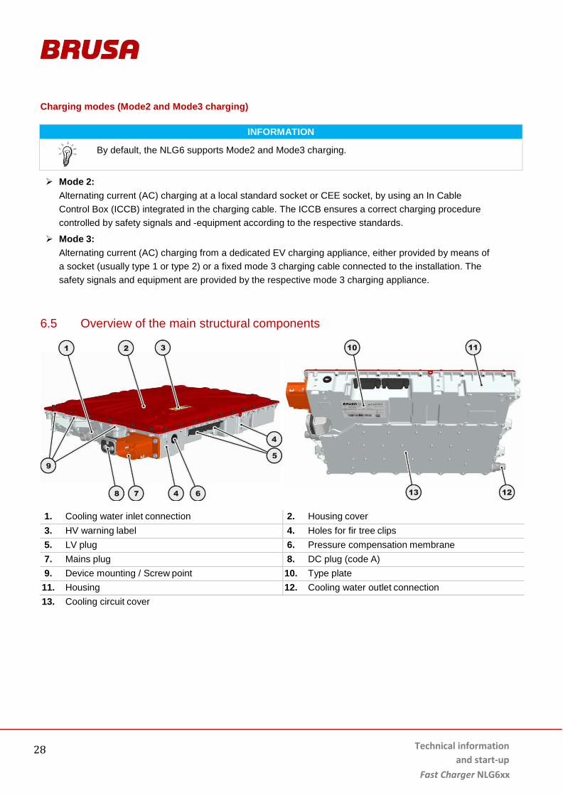
6.5 Overview of the main structural components
1. Cooling water inlet connection 2. Housing cover 3. HV warning label 4. Holes for fir tree clips 5. LV plug 6. Pressure compensation membrane 7. Mains plug 8. DC plug (code A) 9. Device mounting / Screw point 10. Type plate 11. Housing 12. Cooling water outlet connection 13. Cooling circuit cover
Technical information and start-up Fast Charger NLG6xx
29
6.6 Dimensions and installation information For the installation of the charger, the following must be adhered to:
The charger must be installed at a secure location out of reach of the user of the vehicle. This is to
prevent dangers such as accidental touching of HV components or skin burns on the hot housing.
When selecting the installation location, it must be ensured that the pressure compensation membrane on the housing and the connectors are situated above the wading depth of the respective vehicle.
Despite its high IP protection class, the charger should be installed at a dry location, safe from splashing water, dirt and stone chipping.
The tightness of the battery charger can only be guaranteed if all signal wires to the signal connectors are assembled and connected to a tight unit on both sides. If this is not the case for a cable or wire, it must be sealed separately.
The mechanical fixture is to be designed in such a way, that the device is installed in a fixed position and with as little vibrations as possible.
The device must not be operated without a functioning cooling system. Failure to do so will result in permanent loss of the function of the unit.
Cooling water ducts must have sufficient play and must not come into contact with sharp-edged components.
All cable connections must be secured with strain relief elements near the device (not included in the scope of delivery).
Cable connections must have sufficient play and must not come into contact with sharp-edged components.
The housing cover should be sufficiently ventilated (no heat accumulation).
Technical information and start-up
Fast Charger NLG6xx
30
6.6.1 Fixing points
1. Device mounting
M8 x 20 screw Torque = 25 Nm
2. Holes for attachment of fir tree clips
Technical information and start-up Fast Charger NLG6xx
31
6.6.2 Dimensions
6.6.3 Installation position
INSTRUCTION The charger should be installed horizontally (housing cover aligned horizontally). Maximum tilting of 60° on graphically displayed sides is permitted. Deviating installation positions may lead to insufficient cooling performance and damage to the charger! Due to the position of the pressure compensation membrane, the charger should be installed inclined upwards as shown on the right.
α = 60° β = 60°
Technical information and start-up
Fast Charger NLG6xx
32
6.7 Vehicle installation basic principle
Technical information and start-up Fast Charger NLG6xx
33
6.8 Block diagram
Technical information and start-up
Fast Charger NLG6xx
34
6.9 Type plate
1. Manufacturer address 2. Series number and date of production 3. Supplier number (specified by the customer) 4. Space for customer specific labels 5. 3D bar code 6. 2D bar code 7. IP protection class not connected 8. IP protection class fully connected 9. Max. DC side charging capacity 10. Max. AC side charging capacity 11. Hardware product number
(specified by the customer) 12. Scope of delivery product number
(specified by the customer) 13. Classification
Technical information and start-up Fast Charger NLG6xx
35
7 Connections
7.1 Electrical
INFORMATION Information about required mating plug types can be found in the chapter of the respective plug, or on the charger drawing.
1. Grounding screw GND (equipotential bonding)
for M6 x 20 screw Torque = 12.5 Nm refer to chapter 7.1.1 Grounding Screw (equipotential bonding)
2. DC plug (code A) refer to chapter 7.1.2 Pin assignment DC plug (Code A, device side)
1. Kl30 +12 V (plus wiring system) 2. EV_CAN_H EV CAN high 3. Kl30C Kl30 Crash 4. HVIL_out HV interlock loop output 5. --- not connected 6. --- not connected 7. Kl31 Ground (minus wiring system) 8. EV_CAN_L EV CAN low 9. HVIL_in HV interlock loop input 10. HW_WakeUp Hardware wake up (input) 11 Debug_CAN_H CAN high Debug 12. Debug_CAN_L CAN low Debug
7.1.4.1 Pin 1 Kl30
INSTRUCTION At this pin, supply voltage may not reach > 27 V under any circumstances! Over this voltage, the device may be severely damaged!
Via pin 1 Kl30, the device is supplied with wiring system voltage.
If AC voltage is connected to the device, internal circuitry is powered from AC and so the power consumption at pin 1 Kl30 is reduced to almost 0 A.
Technical information and start-up
Fast Charger NLG6xx
40
7.1.4.2 Pin 2 EV_CAN_H / Pin 8 EV_CAN_L
INFORMATION These two pins must be connected to the CAN bus of the vehicle. This enables control of the
charger.
This CAN bus offers WakeUp, see chapter 7.3.1 WakeUp via CAN (CAN for Vehicle Control Unit (VCU))
Internal wiring
CAN 2.0B, 500 kBaud
In the charger, there is no termination present (CAN-terminating resistor)
The CAN IDs can be changed by PARAM tool if required.
7.1.4.3 Pin 3 Kl30C
Internal wiring
In case of a crash (other vehicle bumps into charging vehicle), the charger immediately disconnects the energy flow.
Control Pilot is set to status B.
AC voltage is switched off by EVSE.
<1 V conforms to Crash
100n
F
Pin 3 Kl30c
1k 1k
10nF
22k
10k 47
0pF 1,0V
3,2V
Pin 8 EV_CAN_L
Pin 2 EV_CAN_H
33pF
33
pF
TJA1043
Technical information and start-up Fast Charger NLG6xx
41
>5 V conforms to no Crash
Technical information and start-up
Fast Charger NLG6xx
42
7.1.4.4 Pin 4 HVIL_out / Pin 9 HVIL_in
Internal wiring
The (externally created and evaluated) interlock signal is transmitted over the DC plug. As a result, the correct connection of the DC plug is constantly monitored. If the DC plug is disconnected or not properly locked, the charger and battery should immediately be switched off by the external interlock system, so dangerous situations can be avoided.
7.1.4.5 Pin 7 Kl31
This pin is directly connected to the housing (ground connection).
7.1.4.6 Pin 10 HW_WakeUp
Internal wiring
Via this pin (HW_WakeUp), the charger can be woken up from sleep state. Refer to chapter 7.3.3 WakeUp via Pin HW-WakeUp
100n
F
Pin 10 HW_WakeUp
1k
10nF
1k
10k
1,0V
3,2V
22k
Pin 4 HVIL_OUT
Pin 9 HVIL_IN
470p
F
22Ω
470p
F
49kΩ
49kΩ
DC-Connector
Technical information and start-up Fast Charger NLG6xx
43
7.1.4.7 Pin 11 Debug_CAN_H / Pin 12 Debug_CAN_L
INFORMATION The Debug-CAN bus is designed for troubleshooting. Therefore, its data are only relevant for
the company BRUSA.
If an error occurs on the charger, the data of this CAN bus can also be logged by the customer. This may be helpful in case of an in-depth system diagnosis.
The Debug-CAN bus must not be connected to the vehicle CAN bus, as this may lead to signal disturbances in the CAN network of the vehicle due to bus overload.
Internal wiring
CAN 2.0B, 500 kBaud
In the charger there is no termination (CAN-terminating resistor)
1. POS_S Locking system feedback signal 2. PROX_D Proximity Detection Resistor 3. LED_Green Output LED green 4. LED_Blue Output LED blue 5. RELAY_L1 Plug locking 6. RELAY_L2 --- 7. TEMP_Con Input PT1000 temperature sensor 8. RELAY_U2 Vehicle WakeUp output 9. LED_Red Output LED red 10 RELAY_U1 Plug unlocking 11 CTL_PIL Control Pilot 12 Kl31_out Earth output LED
7.1.5.1 Pin 1 POS_S
Internal wiring
Via pin 1 POS_S the position of the locking drive (open / closed) can be read out.
< 0.5 V corresponds to locking open (no charging)
>5 V corresponds to locking closed (charging is possible)
100n
F
Bolt Pos
1k
10nF
22k
470p
F 1,0V
3,2V
10k
5V
Technical information and start-up Fast Charger NLG6xx
45
Technical information and start-up
Fast Charger NLG6xx
46
7.1.5.2 Pin 2 PROX_D
Via input pin 2 PROX_D the proximity resistor of the charger is measured an interpreted.
The charger assumes that a 4.7 kΩ resistor is installed in the Charge Coupler in addition to the proximity resistor (see chapter 3.4.7. Proximity Detection).
The maximum current of the charging cable is defined by the proximity resistor according to the following table:
Amperage Resistance
Max. 63 A 100 R
Max. 32 A 220 R
Max. 20 A 680 R
Max. 13 A 1 k5
7.1.5.3 Pin 3 LED green / Pin 4 LED_blue / Pin 9 LED_Red
Internal wiring
LEDs are supplied by a PWM pulsed 20 mA constant current source.
The LED current is fed back over pin 12 Kl31_out.
LED
100n
F
100n
F
47k
Pow
er s
uppl
y 20
mA
Volta
ge
mea
sure
men
t
150k
Technical information and start-up Fast Charger NLG6xx
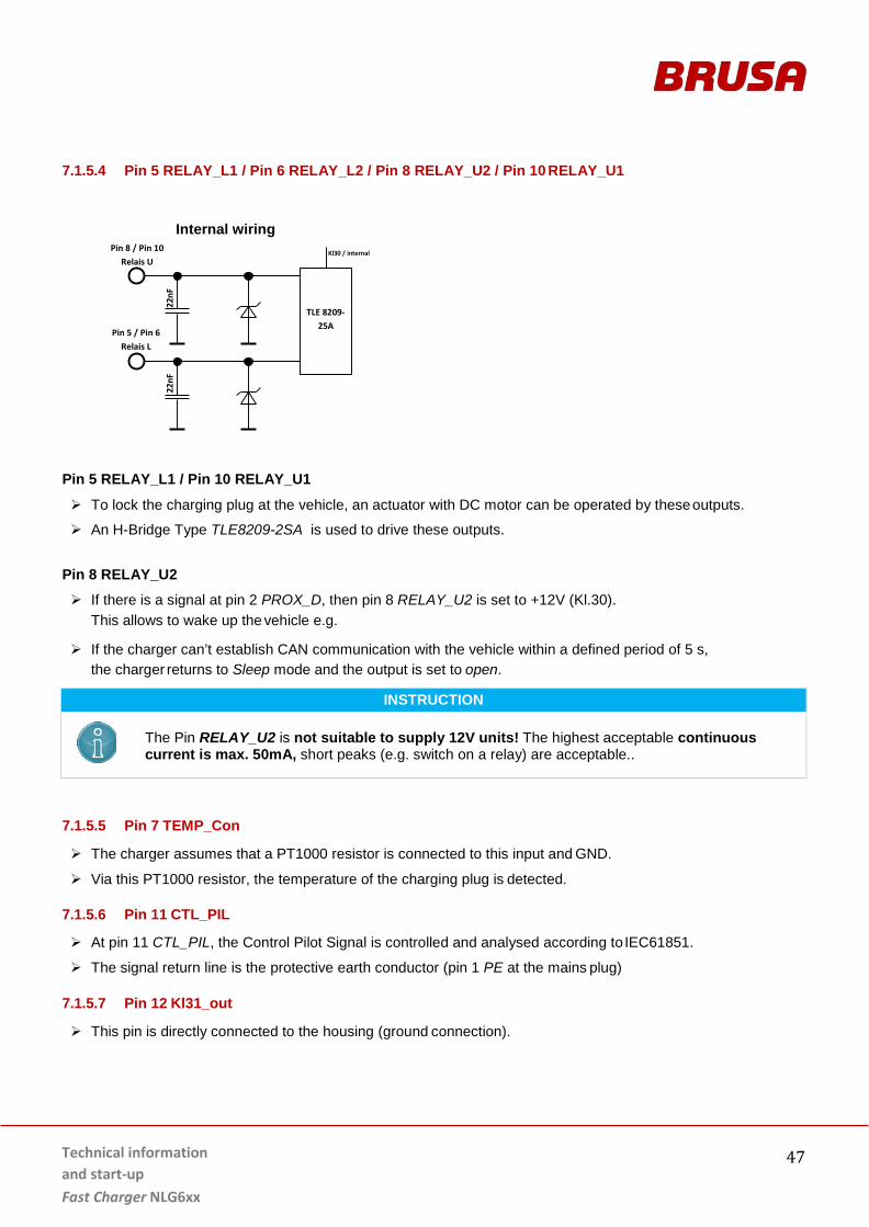
To lock the charging plug at the vehicle, an actuator with DC motor can be operated by these outputs.
An H-Bridge Type TLE8209-2SA is used to drive these outputs.
Pin 8 RELAY_U2
If there is a signal at pin 2 PROX_D, then pin 8 RELAY_U2 is set to +12V (Kl.30). This allows to wake up the vehicle e.g.
If the charger can’t establish CAN communication with the vehicle within a defined period of 5 s, the charger returns to Sleep mode and the output is set to open.
INSTRUCTION
The Pin RELAY_U2 is not suitable to supply 12V units! The highest acceptable continuous current is max. 50mA, short peaks (e.g. switch on a relay) are acceptable..
7.1.5.5 Pin 7 TEMP_Con
The charger assumes that a PT1000 resistor is connected to this input and GND.
Via this PT1000 resistor, the temperature of the charging plug is detected.
7.1.5.6 Pin 11 CTL_PIL
At pin 11 CTL_PIL, the Control Pilot Signal is controlled and analysed according to IEC61851.
The signal return line is the protective earth conductor (pin 1 PE at the mains plug)
7.1.5.7 Pin 12 Kl31_out
This pin is directly connected to the housing (ground connection).
Pin 5 / Pin 6 Relais L
Pin 8 / Pin 10 Relais U
22nF
22
nF
TLE 8209-25A
Kl30 / internal
Technical information and start-up
Fast Charger NLG6xx
48
7.2 Cooling water connections
INSTRUCTION When the cooling system is connected, attention must be paid that the cooling water inlet and outlet are connected correctly! Swapping the connections may lead to malfunctions in the cooling systems and consequently to overheating of the device!
1. Cooling water inlet
(for connection of Normaquick PS3*) 2. Cooling water outlet
(for connection of Normaquick PS3*)
* required inner diameter of cooling water tube = 18 mm
Technical information and start-up Fast Charger NLG6xx
49
7.3 Wakeup mechanism
INFORMATION The NLG6 features several WakeUp mechanisms to wake up the device from sleep. The
following chapters contain an overview and descriptions of the various WakeUp mechanisms.
For a successful WakeUp, AUX voltage must always be between 9 and 16 V.
7.3.1 WakeUp via CAN
As soon as there is any communication on the CAN bus, the charger wakes up.
Technical information and start-up
Fast Charger NLG6xx
50
7.3.2 WakeUp via Proximity
As soon as a charging cable is connected to the charging socket of the vehicle (Charge Coupler), the charger detects the proximity resistor and wakes up. Also refer to chapter 3.4.7 Proximity Detection acc. to IEC 61851
7.3.3 WakeUp via Pin HW-WakeUp
The charger wakes up as soon as voltage at this pin exceeds 4.2 V (edge-controlled event). Now, the charger tries to establish a connection via CAN to the higher-level control system (e.g. VCU).
7.3.4 WakeUp via Control Pilot CP
Control-Pilot (CP) is a standardized safety signal transmitted via an additional conductor in the charging plug. The charging station can wake up the charger via CP signal. This function can be used e.g. to program a specific charging period at the charging station in order to control the charge depending on electricity tariff.
7.3.5 WakeUp via AC (mains voltage)
The charger wakes up as soon as mains voltage is supplied to the contacts of the AC plug.
Technical information and start-up Fast Charger NLG6xx
51
7.4 Power limitations / Limiting controller
INFORMATION To protect the charger and connected peripherals (e.g. HV battery, charging cable, Wallbox) from damage due to overload, several load limits must be considered. The charger continuously monitors whether all operating values are within the permissible range, and reduces charging power if required (derating).
7.4.1 Input current limitation Indem
The input current is limited by the other limiters, the technical limits of the device, the charging cable (Proximity Detection) and the charging station (Control Pilot).
Technical information and start-up
Fast Charger NLG6xx
52
7.4.2 Input power limitation Pndem
The charger permanently monitors the charging power and limits it to a max. of 22 kW. In a 3x230V/400V grid, this corresponds to a phase current of 32 A. The maximum mains capacity is country-specific and directly influences the available charging power. Lower mains capacity respectively leads to lower charging capacity.
7.4.3 Mains voltage dependent limitation
Derating is automatically activated by the charger, if a voltage dip or distorted electrical supply occurs. This relieves the network and the charger continues charging with reduced power. In case of heavily distorted network voltage (very rarely), derating is respectively adjusted to minimize output ripple current.
7.4.4 Proximity Detection
The Proximity Detection system is safety-relevant. Further information can be found in chapter 3.4.7 Proximity Detection acc. to IEC 61851
7.4.5 Control Pilot
The Control Pilot is safety-relevant. Further information can be found in chapter 3.4.1 Control Pilot acc. to SAEJ1772 and / or IEC61851
7.4.6 Temperature derating
Further information can be found in chapter 3.4.5 Overtemperature protection (derating)
7.4.7 Output current limitation Iadem
Maximum output current (Imax) of the charger is 60 A. If battery voltage exceeds 330 V, the charging current is defined by the maximum mains power. For low battery voltages (< 330 V), charging capacity is limited by the maximum output current of 60 A.
7.4.8 Output voltage limitation Uadem
To protect the HV battery from overcharging, the output current is reduced as soon as the end-of-charge voltage is reached. The output current can be reduced to 0 A this way.
The achievable output voltage is 200 – 450 V.
Technical information and start-up Fast Charger NLG6xx
53
8 Efficiency
8.1.1 Level of efficiency 1-phase charging Efficiency vs. charging power single phase charging, at different battery voltages (200VDC / 300VDC).
8.1.2 Level of efficiency 3-phase charging Efficiency vs. charging power three phase charging, at different battery voltages (310VDC, 340VDC, 400VDC)
Technical information and start-up
Fast Charger NLG6xx
54
9 Installation / Start-up
9.1 Installation and connection of charger
DANGER High voltage! Danger to life! If the HV battery is activated, connected HV cables carry high voltage! For this reason, never
connect HV cables without ensuring that the unit is not live!
WARNING Suspended loads! Crushing hazard for feet! When lifting the device out, it may fall down if the lifting equipment is not operated properly!
Do not operate lifting equipment without having received appropriate training!
Always act carefully and avoid jerking movements!
INFORMATION Prior to installation, visually check the packing material and particularly the device itself for damage. Each device undergoes a strict quality and function test at BRUSA before distribution. However, we do not have any influence on shipping and loading of our products.
Procedure step Illustration / Other Information
1. Disconnect the HV supply. Ensure that the HV system is not live!
2. Use appropriate equipment to lift the charger out of
its packaging.
Charger weight = 12 kg
---
3. Remove the protective covers of the electrical connectors (DC plug, mains plug and LV plug). ---
4. Use fir tree clips (1) on the housing as applicable (up to 4 clips).
Technical information and start-up Fast Charger NLG6xx
55
Procedure step Illustration / Other Information 5. Carefully install the charger at its installation
location.
Fasten the screws (1).
If mounting plates (adapter plates) are to be used, these must be attached to the charger first.
Torque = 20 Nm +/- 2 Nm
6. Remove covers (1) of the cooling water
connections.
7. Connect the cooling water connections (1) and (2)
to the charger.
Always check that cooling water inlet (1) and cooling water outlet (2) are connected correctly!
Ensure that the PS3 quick connection of both connections is properly engaged! Manually check if the connection is secure!
Technical information and start-up
Fast Charger NLG6xx
56
Procedure step Illustration / Other Information 8. Establish earth connection to the chassis.
The charger is equipped with three earth connections (1), (2) and (3). At least one earth connector must be connected!
Torque = 12.5 Nm +/- 1.5 Nm
For information on earth connection refer to chapter 7.1.1 Grounding Screw (equipotential bonding)
9. Connect the LV plugs (1) and (2) to the charger.
Manually check if the LV plugs (1) and (2) are fastened securely!
Always ensure suitable mounting of the required strain relief elements!
The tightness of the battery charger can only be guaranteed if all the signal cables to the signal connectors are packaged and connected to a tight unit. If this is not the case in one of the cables, it must be sealed separately.
10. Connect the mains plug (1) to the charger.
Manually check if the mains plug (1) is secure!
Always ensure suitable mounting of the required strain relief element!
Technical information and start-up Fast Charger NLG6xx
57
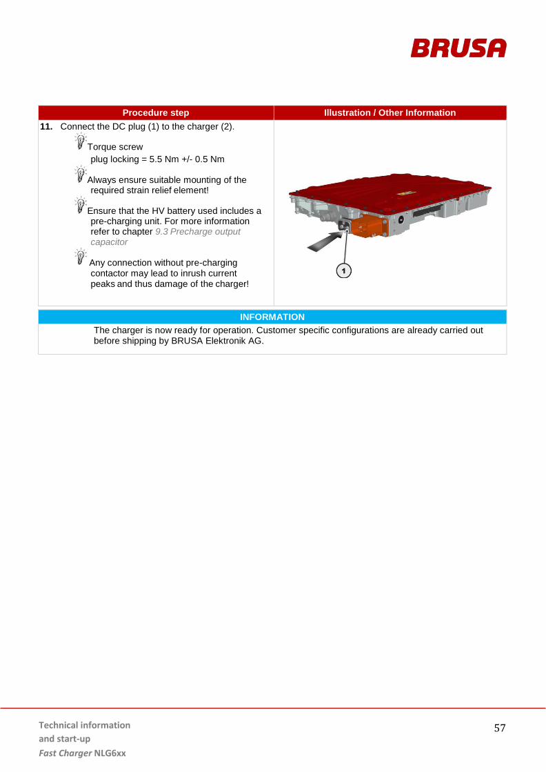
Procedure step Illustration / Other Information 11. Connect the DC plug (1) to the charger (2).
Torque screw plug locking = 5.5 Nm +/- 0.5 Nm
Always ensure suitable mounting of the required strain relief element!
Ensure that the HV battery used includes a pre-charging unit. For more information refer to chapter 9.3 Precharge output capacitor
Any connection without pre-charging contactor may lead to inrush current peaks and thus damage of the charger!
INFORMATION The charger is now ready for operation. Customer specific configurations are already carried out before shipping by BRUSA Elektronik AG.
Technical information and start-up
Fast Charger NLG6xx
58
9.2 Removing the charger
Procedure step Illustration / Other Information
1. Disconnect the HV supply. Ensure that the HV system is not live!
2. Secure the system against restarting by
other personnel! ---
3. Disconnect the DC plug (1) from the charger.
DANGER
WARNING
High voltage! Danger to life!
If the HV battery is activated, HV cables carry high voltage! Under no circumstances carry out work on the device without first ensuring that there is no voltage in the HV system!
High voltage! Danger to life!
After disconnecting the mains and DC connections, the charger requires approx. 5s to discharge its capacitors. This time period must always be observed before carrying out further work, in order to avoid electrical shocks!
Suspended loads! Crushing hazard for feet!
When lifting the device out, it may fall down if the lifting equipment is not operated properly!
Do not operate lifting equipment without having received appropriate training!
Always act carefully and avoid jerking movements!
Technical information and start-up Fast Charger NLG6xx
59
Procedure step Illustration / Other Information 4. Disconnect the mains plug (1) from the charger.
5. Wait at least 5 seconds before performing the
following steps.
Capacitors are discharged
6. Disconnect the LV plugs (1) and (2) from the charger.
7. Disconnect the earth connection from the charger.
The charger is equipped with three ground connections (1), (2) and (3). At least one of them needs to be connected to achieve proper grounding.
Technical information and start-up
Fast Charger NLG6xx
60
Procedure step Illustration / Other Information 8. Disconnect the cooling water connections (1) and (2)
from the charger.
These connections are achieved with PS3 quick connections.
9. Attach the covers (1) to the cooling water
connections.
10. Remove all cables attached to the charger, e.g. at
the fir tree clips (1).
11. Ensure that all connections have been disconnected
from the charger and no connections remain (e.g. wire connectors).
---
Technical information and start-up Fast Charger NLG6xx
61
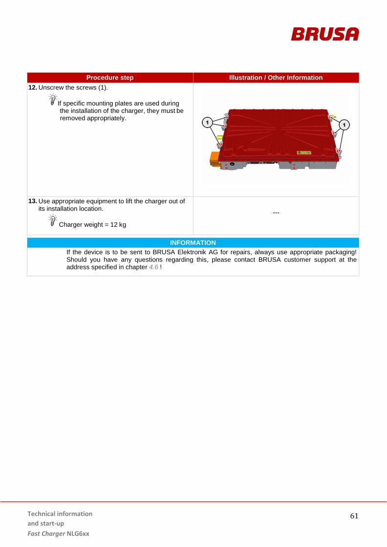
Procedure step Illustration / Other Information 12. Unscrew the screws (1).
If specific mounting plates are used during the installation of the charger, they must be removed appropriately.
13. Use appropriate equipment to lift the charger out of
its installation location.
Charger weight = 12 kg
---
INFORMATION If the device is to be sent to BRUSA Elektronik AG for repairs, always use appropriate packaging! Should you have any questions regarding this, please contact BRUSA customer support at the address specified in chapter 4.6 !
Technical information and start-up
Fast Charger NLG6xx
62
9.3 Precharge output capacitor
HINWEIS
In order to avoid the formation of sparks (and/or damage to the device) when connecting the charger to the battery, the internal capacity of 24.5 uF must always be pre-charged from the battery’s DC-link via a pre-charging resistor!
When using a PTC as pre-charging resistor, the latter may heat up in case of multiple subsequent pre-charging attempts. If the PTC gets hot, pre-charging is temporarily not possible. In that case, the PTC needs to cool down for some time before attempting to pre-charge again.
Technical information and start-up Fast Charger NLG6xx
63
The process of pre-charging is as follows:
1. The main contactor HV- (3) closes. 2. The pre-charging contactor (1) closes.
Ensure that the pre-charging contactor (1) as well as the pre-charging resistor RP (4) are designed for the maximum pre-charging current. Please note that the pre-charging contactor (1) must be able to interrupt the pre-charging current in the case of a fault! Monitor the pre-charging time and open the pre-charging contactor (1) again if the condition U1 - U2 < 10 V is not fulfilled even after a specified maximum period.
3. The main contactor HV+ (2) closes. The main contactor (2) may only close if the condition U1 - U2 < 10 V is fulfilled.
4. The pre-charging contactor (1) opens. The HV connection to the device is now established.
10 Operation
INFORMATION
The unit is controlled via CAN, please see Software Manual for more information. Also refer to chapter 4.2 Scope of the documentation.
11 Warranty and Guarantee The warranty corresponds to the regulations in our currently valid general terms and conditions see under www.brusa.biz/en/support/terms-conditions.html.
12 Instructions regarding disposal
A basic requirement for the re-use and recycling of used electronic devices is the correct disposal. With the implementation of the electric and electronic device regulation (ElektroG), since 24 March 2006, electronic devices may no longer be disposed of along with ordinary household waste but must be separately collected and recorded by a specialist services. Disposal through a specialist service significantly helps to avoid dangers to people and nature. Therefore, in the case of disposal, we recommend contacting a recognised specialist disposal service.
Installation into the vehicle .................................................. 32 NLG6xx .................................................................................. 33
C CAN specification ....................................................................... 24 control connector LV
Code A ................................................................................... 39 Control connector LV ................................................................. 35
Code B ................................................................................... 43 Control Pilot................................................................... 15, 43, 49 Cooling system..................................................................... 16, 46 Customer package ..................................................................... 20
L LED pin assignment .................................................................... 44 Level of efficiency ...................................................................... 51
N Notes on assembly ..................................................................... 13 Notes on life span ...................................................................... 13
Important instructions .......................................................... 12 Safety installations ..................................................................... 24 Serial number ............................................................................. 34
T Technical properties ..............................................................7, 26 Thermal / Cooling system .......................................................... 23
V Validity ......................................................................................... 3 Voltage pre-charging .................................................................. 61
W WakeUp mechanism ............................................................47, 48 Warranty .................................................................................... 20