Page 1
Fast Handover Using Explicit Multicast for IPv6-based
Wireless LAN Networks
Lei LI
DOCTOR OF
PHILOSOPHY
Department of Informatics,
School of Multidisciplinary Sciences,
the Graduate University for Advanced Studies (SOKENDAI)
2005 (School Year)
July 2005
Page 2
Fast Handover Using Explicit Multicast for
IPv6-based Wireless LAN Networks
Abstract
This thesis is devoted to improve the service performance for the multimedia
traffics in wireless LAN networks. Review of TCP/IP model and Wireless LAN are
conducted. An abstract model of network mobility framework is achieved based on
investigating the state of art of mobility support. By the analysis of this model, we
propose a new Xcast based scheme (X&M) to improve the deficiencies of Mobile IP
(v4/v6). We evaluate the improvement of its handover performance and conduct
the simulation to compare the different handover performance of X&M scheme and
other existing schemes. We also propose to two-level mobility for wireless LAN
based on the study of network mobility. Finally we argue that the two proposals
can be used together to achieve good service performance for wireless multimedia
communication in wireless LAN.
Page 3
Acknowledgements
First and foremost, I would like to express my profound gratitude to my research
supervisor Assoc. Prof. Shunji Abe for leading me toward the completion of this
dissertation. This work could never have been completed without his invaluable
directions, enlightenment, advices and constants support. Also I would like to thank
other supervisors, Prof. Shigeki Yamada and Prof. Toru Hasegawa, and other
professors, Assoc. Prof. Yusheng Ji and Prof. Noboru Sonehara, for their guidance
and their valuable comments.
This Ph.D. has been financially supported by NTT DATA Corporation and NII.
I would like to thank all people in the above cited organizations that supports me
to finish my Ph.D.
I
Page 4
Contents
Contents II
List of Figures VI
List of Tables VIII
1 Introduction 1
1.1 Motivations and Objectives . . . . . . . . . . . . . . . . . . . . . . . 1
1.2 Organization of This Dissertation . . . . . . . . . . . . . . . . . . . . 4
2 IP-based Networks 6
2.1 Terminology . . . . . . . . . . . . . . . . . . . . . . . . . . . . . . . . 7
2.1.1 Mobile Host . . . . . . . . . . . . . . . . . . . . . . . . . . . . 7
2.1.2 Mobile Network . . . . . . . . . . . . . . . . . . . . . . . . . . 8
2.2 Network-layer Mobility . . . . . . . . . . . . . . . . . . . . . . . . . . 10
2.3 Handover Classification . . . . . . . . . . . . . . . . . . . . . . . . . 11
2.3.1 Classified by the Number of Access Points Involved . . . . . . 11
2.3.2 Classified by Initiation of Handover . . . . . . . . . . . . . . . 12
2.4 Architecture of IP-Based Networks . . . . . . . . . . . . . . . . . . . 13
2.5 Routing . . . . . . . . . . . . . . . . . . . . . . . . . . . . . . . . . . 15
2.5.1 Unicast Routing . . . . . . . . . . . . . . . . . . . . . . . . . 15
2.5.2 Traditional Multicast Routing . . . . . . . . . . . . . . . . . . 16
2.5.3 Traditional Multicast versus Small Group Multicast . . . . . . 18
2.6 IP-based Wireless LAN Networks . . . . . . . . . . . . . . . . . . . . 19
2.6.1 Wireless LAN . . . . . . . . . . . . . . . . . . . . . . . . . . . 20
II
Page 5
Contents III
3 Mobility Support: State of the Art 22
3.1 IETF Mobility Support Schemes . . . . . . . . . . . . . . . . . . . . . 22
3.1.1 Mobile IP Fundamentals . . . . . . . . . . . . . . . . . . . . . 22
3.1.2 Mobile IPv4 . . . . . . . . . . . . . . . . . . . . . . . . . . . . 23
3.1.3 Mobile IPv4 and Mobile Networks . . . . . . . . . . . . . . . . 24
3.1.4 Mobile IPv4 and Mobile Networks . . . . . . . . . . . . . . . . 25
3.1.5 IETF Hierarchical Mobile IPv6 . . . . . . . . . . . . . . . . . 26
3.2 Mobility Support Approaches . . . . . . . . . . . . . . . . . . . . . . 28
3.2.1 Cellular IP . . . . . . . . . . . . . . . . . . . . . . . . . . . . . 28
3.2.2 HAWAII . . . . . . . . . . . . . . . . . . . . . . . . . . . . . 28
3.2.3 Fast Handover Enhancement . . . . . . . . . . . . . . . . . . . 29
3.2.4 Helmy . . . . . . . . . . . . . . . . . . . . . . . . . . . . . . . 29
3.2.5 DNS Updates . . . . . . . . . . . . . . . . . . . . . . . . . . . 30
3.3 Mobility Support Architectures . . . . . . . . . . . . . . . . . . . . . 30
3.4 Network Mobility . . . . . . . . . . . . . . . . . . . . . . . . . . . . . 31
3.4.1 Prefix Scope Binding Updates . . . . . . . . . . . . . . . . . . 31
3.4.2 IETF NEMO Basic Protocol . . . . . . . . . . . . . . . . . . . 32
4 Problem Statement and Requirements 33
4.1 Objectives . . . . . . . . . . . . . . . . . . . . . . . . . . . . . . . . . 33
4.2 Design Requirements . . . . . . . . . . . . . . . . . . . . . . . . . . . 34
4.3 IP Mobility Support in the Literature . . . . . . . . . . . . . . . . . . 39
4.3.1 Macro-mobility . . . . . . . . . . . . . . . . . . . . . . . . . . 39
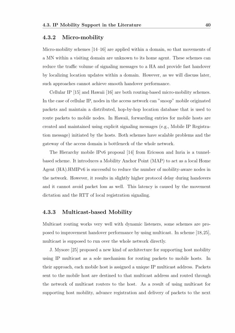
4.3.2 Micro-mobility . . . . . . . . . . . . . . . . . . . . . . . . . . 40
4.3.3 Multicast-based Mobility . . . . . . . . . . . . . . . . . . . . . 40
4.3.4 Xcast-based Mobility . . . . . . . . . . . . . . . . . . . . . . . 41
4.4 Summary . . . . . . . . . . . . . . . . . . . . . . . . . . . . . . . . . 41
5 The Proposed Xcast Based Micro-mobility (X&M) 43
5.1 Candidate Access Router Discovery (CARD) Protocol . . . . . . . . . 43
5.1.1 Introduction . . . . . . . . . . . . . . . . . . . . . . . . . . . . 43
5.1.2 Functional Overview . . . . . . . . . . . . . . . . . . . . . . . 45
Page 6
Contents IV
5.1.3 Approaches for Candidate Access Router Discovery . . . . . . 46
5.2 X&M Mechanism . . . . . . . . . . . . . . . . . . . . . . . . . . . . . 49
5.2.1 Reducing the Delay Due to 802.11 Channel Scanning . . . . . 52
5.2.2 Reducing the Delay Due to the Mobile IP Registration Pro-
cedure . . . . . . . . . . . . . . . . . . . . . . . . . . . . . . . 54
5.3 Handover Procedure of X&M . . . . . . . . . . . . . . . . . . . . . . 54
5.4 Adaptive Algorithm of CAT Threshold Selection . . . . . . . . . . . . 59
5.5 Summary . . . . . . . . . . . . . . . . . . . . . . . . . . . . . . . . . 61
6 Two-level Mobile Routing System 63
6.1 Handover of the Local Node . . . . . . . . . . . . . . . . . . . . . . . 65
6.1.1 Functions in the LN . . . . . . . . . . . . . . . . . . . . . . . 67
6.1.2 Functions in the HA . . . . . . . . . . . . . . . . . . . . . . . 67
6.1.3 Functions in the MR . . . . . . . . . . . . . . . . . . . . . . . 67
6.2 Route Optimization and Seamless Handover of MR . . . . . . . . . . 68
7 Simulation Evaluation Models and Results 70
7.1 Simulation Model Requirements . . . . . . . . . . . . . . . . . . . . . 70
7.2 Simulation Network Model . . . . . . . . . . . . . . . . . . . . . . . . 70
7.2.1 Network topology . . . . . . . . . . . . . . . . . . . . . . . . . 70
7.3 Value of CAT Threshold . . . . . . . . . . . . . . . . . . . . . . . . . 72
7.4 Performance Metrics . . . . . . . . . . . . . . . . . . . . . . . . . . . 73
7.4.1 Handover Latency . . . . . . . . . . . . . . . . . . . . . . . . 73
7.4.2 UDP Packet Loss and Duplication Caused by Handover . . . . 75
7.5 Simulation Results and Evaluations . . . . . . . . . . . . . . . . . . . 76
7.5.1 Unidirectional Movement . . . . . . . . . . . . . . . . . . . . . 76
7.5.2 Bi-directional Movement . . . . . . . . . . . . . . . . . . . . . 81
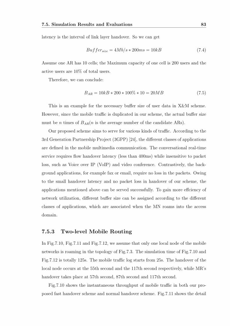
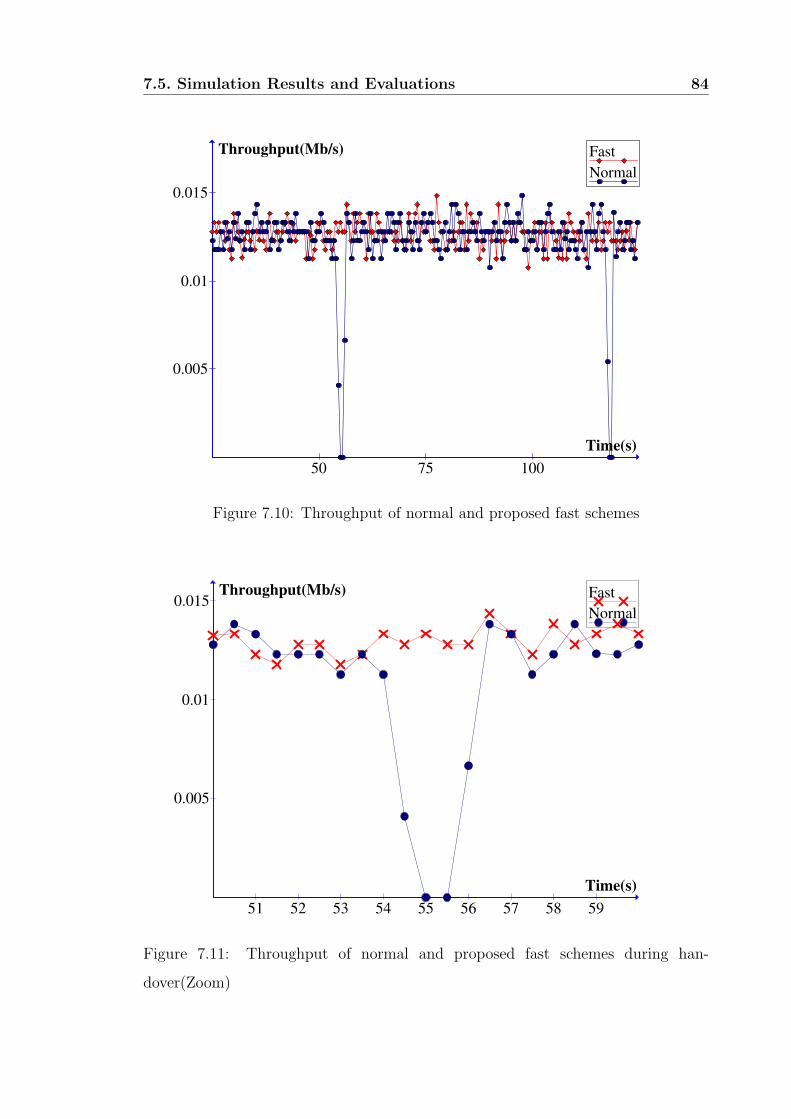
7.5.3 Two-level Mobile Routing . . . . . . . . . . . . . . . . . . . . 83
7.6 Summary . . . . . . . . . . . . . . . . . . . . . . . . . . . . . . . . . 85
8 Mobility Model 87
8.1 Abstraction Model . . . . . . . . . . . . . . . . . . . . . . . . . . . . 87
Page 7
Contents V
8.1.1 Bhagwat’s Abstraction Model . . . . . . . . . . . . . . . . . . 87
8.1.2 A More Detailed Abstraction Model . . . . . . . . . . . . . . . 88
8.2 Mobility Support Frameworks . . . . . . . . . . . . . . . . . . . . . . 91
8.2.1 Routing-based Framework . . . . . . . . . . . . . . . . . . . . 92
8.2.2 Two-Tier Addressing Category . . . . . . . . . . . . . . . . . 93
8.3 Analysis of the Framework . . . . . . . . . . . . . . . . . . . . . . . 101
8.4 Summary . . . . . . . . . . . . . . . . . . . . . . . . . . . . . . . . . 104
9 Conclusions and Perspectives 106
9.1 Conclusions . . . . . . . . . . . . . . . . . . . . . . . . . . . . . . . . 106
9.2 Perspectives and Future Work . . . . . . . . . . . . . . . . . . . . . . 107
Bibliography 109
List of Publications 116
Page 8
List of Figures
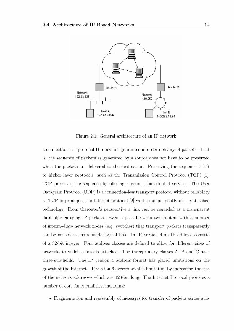
2.1 General architecture of an IP network . . . . . . . . . . . . . . . . . . 14
3.1 Mobile IPv4 network architecture . . . . . . . . . . . . . . . . . . . . 24
4.1 Classification of IP applications with respect to their requirements . . 36
5.1 A message flow for L2 beacon-based discovery . . . . . . . . . . . . . 50
5.2 Xcast based HMIPv6 scheme . . . . . . . . . . . . . . . . . . . . . . . 51
5.3 Signal strength threshold values . . . . . . . . . . . . . . . . . . . . . 55
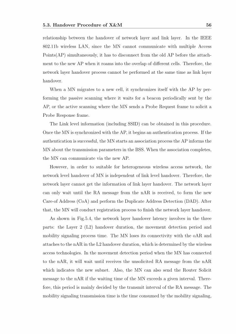
5.4 The L2 handover & the L3 handover in wireless LAN . . . . . . . . . 57
5.5 Handover procedure of X&M scheme in Wireless LAN . . . . . . . . . 58
5.6 The general adaptive algorithm for CAT selection . . . . . . . . . . . 61
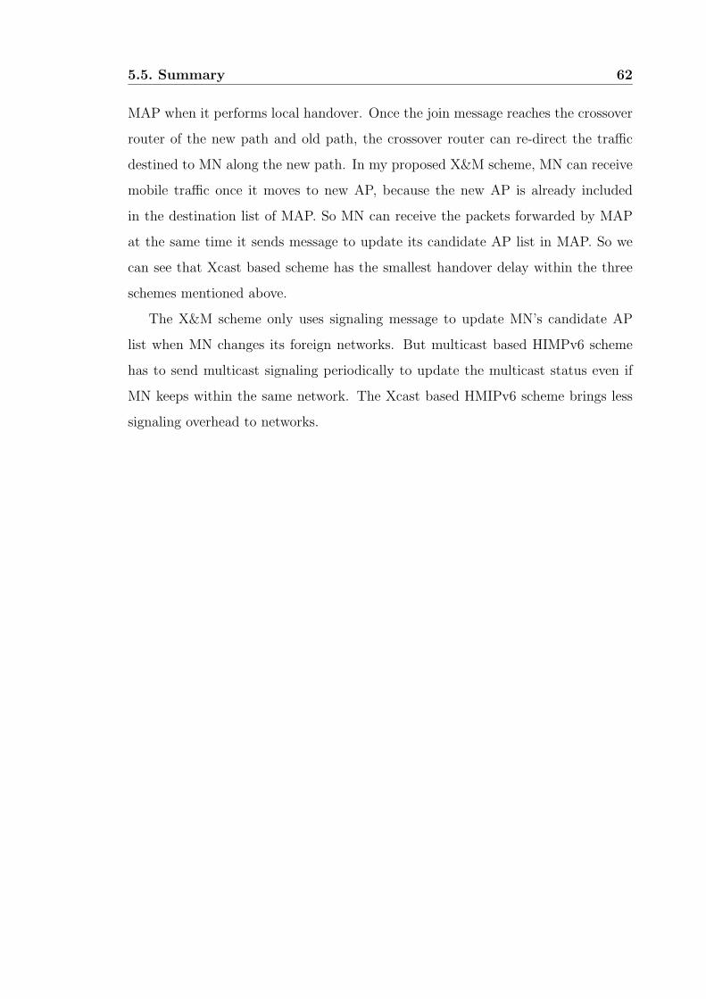
6.1 Handover procedure of LN . . . . . . . . . . . . . . . . . . . . . . . . 64
6.2 Proposed fast handover for LN . . . . . . . . . . . . . . . . . . . . . . 66
6.3 Xcast in two-level mobility system . . . . . . . . . . . . . . . . . . . . 69
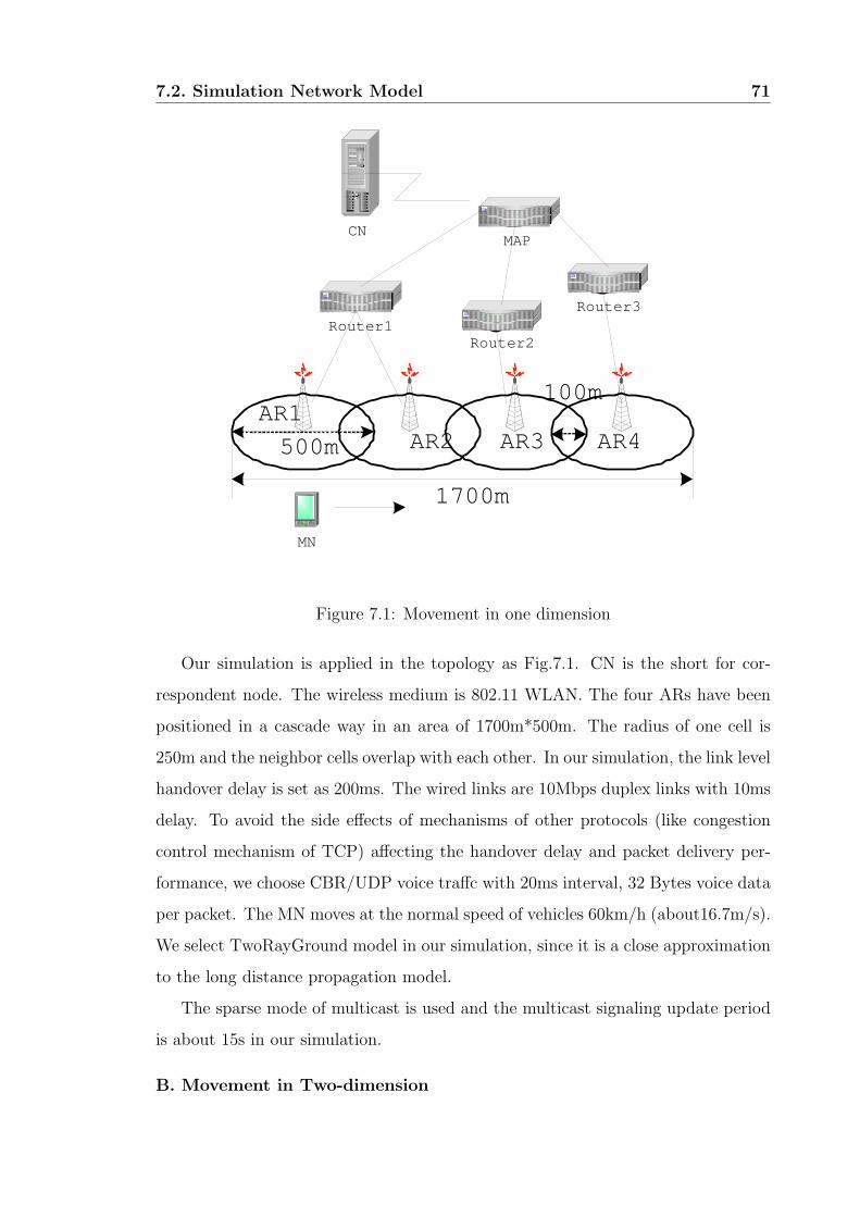
7.1 Movement in one dimension . . . . . . . . . . . . . . . . . . . . . . . 71
7.2 Movement in two-dimension . . . . . . . . . . . . . . . . . . . . . . . 72
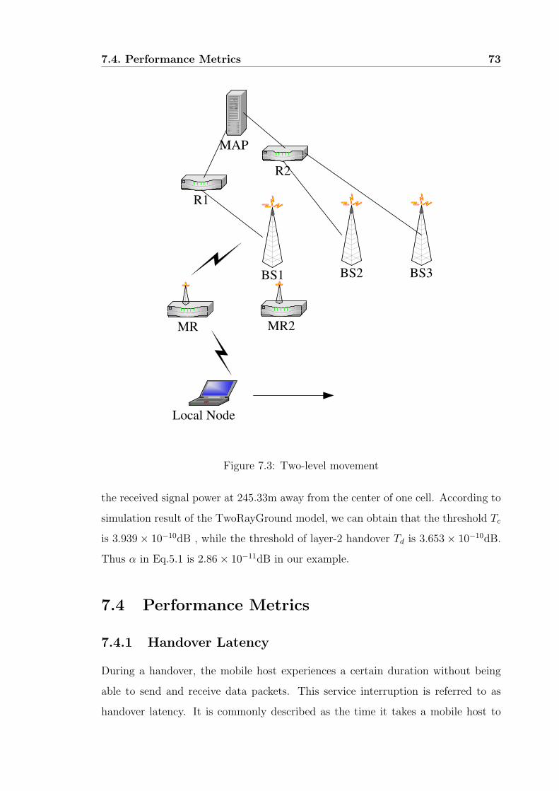
7.3 Two-level movement . . . . . . . . . . . . . . . . . . . . . . . . . . . 73
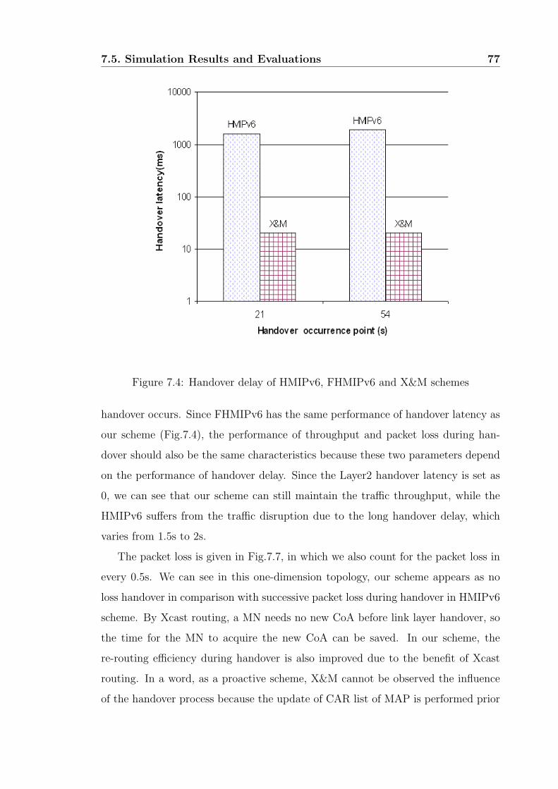
7.4 Handover delay of HMIPv6, FHMIPv6 and X&M schemes . . . . . . 77
7.5 Throughput of HMIPv6 and X&M schemes . . . . . . . . . . . . . . . 78
7.6 Throughput of HMIPv6 and X&M schemes during handover (zoom) . 78
7.7 Packet loss of HMIPv6 and X&M schemes . . . . . . . . . . . . . . . 80
7.8 Bandwidth overhead of HMIPv6, multicast and X&M schemes . . . . 80
7.9 Re-routing during handover for HFMIPv6 and X&M schemes . . . . . 81
7.10 Throughput of normal and proposed fast schemes . . . . . . . . . . . 84
VI
Page 9
List of Figures VII
7.11 Throughput of normal and proposed fast schemes during handover(Zoom) 84
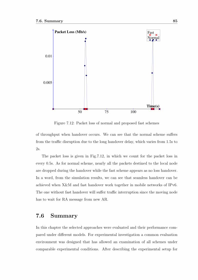
7.12 Packet loss of normal and proposed fast schemes . . . . . . . . . . . . 85
8.1 Location directory framework . . . . . . . . . . . . . . . . . . . . . . 95
8.2 Third party framework . . . . . . . . . . . . . . . . . . . . . . . . . . 95
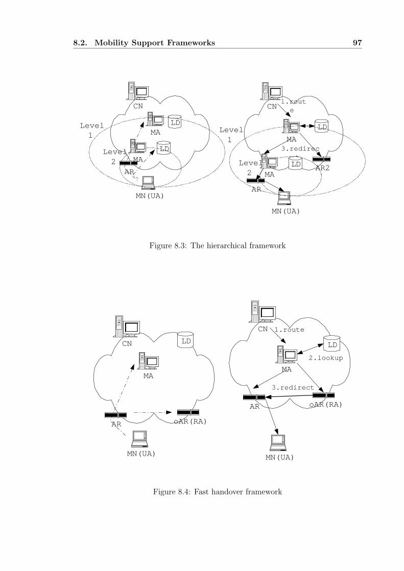
8.3 The hierarchical framework . . . . . . . . . . . . . . . . . . . . . . . 97
8.4 Fast handover framework . . . . . . . . . . . . . . . . . . . . . . . . . 97
8.5 Multicast and Xcast framework . . . . . . . . . . . . . . . . . . . . . 101
Page 10
List of Tables
7.1 Packet loss rate . . . . . . . . . . . . . . . . . . . . . . . . . . . . . . 81
7.2 Network overhead . . . . . . . . . . . . . . . . . . . . . . . . . . . . . 82
8.1 Protocols of the frameworks . . . . . . . . . . . . . . . . . . . . . . . 102
8.2 Taxonomy of proposals . . . . . . . . . . . . . . . . . . . . . . . . . . 104
VIII
Page 11
Chapter 1
Introduction
1.1 Motivations and Objectives
As we see in today’s life, geographical mobility of people is increasing. This is
the result of the pressure of the professional life and the family scattering, which
impact the social life, this in turn generating a need for more mobility. In these
conditions, anyone would wish to benefit from the same social and professional
environment without restriction of the current geographical location. The Era of
digital information could in a way achieve this wish. More and more executives or
representatives are expecting to transfer files from their workplace file system, to
obtain on-line information, to communicate with their customers and providers as if
they were at their office in front of their computer. Similarly, a traveller would like
to stay in touch with his family and friends, sending them photographs and sounds,
while listening to its favorite music. As a result from this, there is a continuous
interest in the Internet, the most appropriate media for digital information exchange,
while cellular telephony gives people the opportunity to be reachable anywhere.
Despite this, the cellular network is currently tuned to carry voice only although
there is also a desire to transmit other types of data, whereas the Internet doesn’t
allow effective mobile communications as in cellular telephony.
At the same time that mobility of people is required, recent advances in computer
miniaturization and wireless technology promise increasingly powerful, light, small
and functional wireless devices. As more and more people are travelling with a
1
Page 12
1.1. Motivations and Objectives 2
laptop, a PDA, a WAP or i-mode phone, a digital camera, or any other high-tech
device, there is a desire to connect it to the Internet from anywhere, at anytime, and
to remain permanently connected to it without any disruption of service. No one
should be abstained from using its usual computing resources and Internet access
while moving, especially when travelling by train or by plane. However, the Internet
it is not tuned to allow mobility in the midst of data transfers because protocols
used in the Internet are not conceived for devices that frequently change their point
of attachment in the Internet topology. Basically, something similar to cellular
telephony as compared to fixed telephony is needed in the Internet. The Internet
must be upgraded with mobility support.
Indeed, mobility support is not only concerned with mobile devices. There are
situations where an entire network could migrate in the Internet topology, which
we refer to as a mobile network. Applications include networks attached to peo-
ple (Personal Area Network or PAN) and networks of sensors deployed in aircrafts,
boats, cars, trains, etc. For instance, an airline or a train company could provide
permanent on-board Internet access, allowing passengers to use their laptop, PDA,
or mobile phone to connect to remote hosts, download music or video, browse the
web, etc. During an international fare, the aircraft or the train changes its point of
attachment to the Internet and gets Internet access from distinct Internet Service
Providers. Similarly, a coach, the metropolitan public transport, or the taxi com-
pany could allow passengers to connect their PAN to the Internet via the embarked
network, therefore ensuring, while on-board, an alternative to the metropolitan cel-
lular network, in terms of price or available bandwidth, access control, etc.
The wireless Internet consists of multiple wireless IP access networks and wired
IP networks that interconnect wireless IP access networks. Certainly, most wireless
IP nodes will be mobile and thus they will change their point of network attachment.
There are two types of network attachment points: base station and access router.
The base station is a link layer device that provides connectivity between wireless
hosts and the wired network. The access router is the edge router in the wireless
IP access network that provides routing services for the wireless hosts. Therefore, a
wireless IP node is involved in two types of handovers: link-layer handover that is
Page 13
1.1. Motivations and Objectives 3
between two base stations and IP-layer handover that is between two access routers.
In most cases, an IP-layer handover is accompanied by a link-layer handover.
The IP address often plays two roles in the Internet: identifier for routing and
identifier for the node. Network applications deal with IP addresses directly when
establishing direct connections with the application entities in the remote nodes in
which the IP address is the node identifier. In this sense, it is desirable to use the
same IP address regardless of the location of the node. On the other hand, when
the node changes its topological location by moving from an IP subnet to another
subnet, the node should get a new IP address that is routable. By routable we mean
that the IP packets destined to the mobile node should have the new IP address
valid in the new subnet after the handover.
The task of mobility management in the wireless Internet is basically enabling
network applications to continuously operate, at the required quality of service
(QoS), in the wireless mobile nodes throughout an IP-layer handover.
Handovers can be handled in various layers. The link layer is not appropriate
to handle IP-layer handover because typically link layer protocols do not carry IP-
layer information. Modifying lots of link layer protocols to support IP mobility
management would not be practical or feasible. If the network application is aware
of an IP-layer handover, certainly the application entities can facilitate a handover
by simply informing the peer application entity of the new IP address. In our
research we focus on fast handover and mobility management in the network layer.
The advantage of network layer mobility management is that the transport layer or
applications do not see IP address change due to handover.
Our main contribution of this dissertation is as follows:
Based on the study of the existing works on the mobility management, we pro-
pose an efficient seamless handover scheme (X&M) for the WLAN road information
system. In our proposal, we use explicate multicast routing to forward traffic and a
new layer-2 trigger to get the information of list of potential access routers respec-
tively. Furthermore, it is more feasible than other proactive handover schemes. In
addition, this new trigger can also be used in any case where the information of new
AR is needed in wireless LAN networks. We also present a two-level mobility rout-
Page 14
1.2. Organization of This Dissertation 4
ing system based on our X&M scheme and IETF network mobility (NEMO) basic
protocol to provide large bandwidth for dynamic networks. Finally, we validated
the performance of our solutions by means of simulation, using Ns-2, which required
important enhancements to the publicly available code. Our simulations are mainly
concerned with measuring disruption of throughput caused by the network layer
handover process. Our simulation results showed that our proposal is a seamless
handover solution to the mobile network implemented by wireless LAN.
1.2 Organization of This Dissertation
This Ph.D. dissertation thus investigates issues for fast handover schemes and mo-
bility management in an IPv6 based wireless LAN network. The document is struc-
tured as follows:
In chapter 2, we first define the terminology that we are going to use in this
dissertation, and then we describe IP protocol suite and particularly the network
layer, in charge of node-to-node communication. We give brief review on TCP/IP,
IPv6 and wireless LAN first. We then detail the general problem caused by mobility,
and why the network layer cannot handle it efficiently. As a result of mobility, a
new route must be found. Since the IP address must reflect the location in the
Internet topology, mobility usually generates a change of the physical IP address
every time a node is attached to a new link in the Internet topology. This poses
two questions: how to advertise the new topological location and how to handle the
change of address at the transport layer where the IP address is used as an identifier.
Once the mobility problem is defined, we study the State of the Art in the area of
host mobility support. This study is essential in order to investigate how current
host mobility and network mobility support schemes.
We address the question of mobility support specifically. As a solution based on
Hierarchy Mobile IPv6, we propose a seamless handover scheme, Xcast-based micro-
mobility (X&M) scheme, which is suitable for IEEE 802.11 road wireless communi-
cation system. Here the seamless means nearly no handover delay and low packet
loss during the handover. It often happens that a MN may disconnect from its
Page 15
1.2. Organization of This Dissertation 5
provider for some time which causes packet loss, however, it is out of consideration
in our paper and we suppose the ARs is well arranged to let MN connect with its
provider’s networks all the time.
Explicit multicast (Xcast) is also applied to Hierarchy Mobile IPv6 (HMIPv6)
networks to achieve efficient re-routing during handover. One of our main contri-
bution is to propose an efficient method to get the information of neighbor cells in
the reactive wireless networks as WLAN and accordingly determine the potential
ARs of the given MN, which makes multicast-like fast handover schemes feasible in
WLAN.
X&M scheme can be also applied to mobile networks besides mobile hosts. A
two-level mobile routing system is present to achieve the overall seamless handover
for the local nodes behind the mobile routers.
The performance of our proposal is evaluated by means of simulation. We first
start by the configuration of our simulations and our metrics used for the evaluation.
Then, we conclude by the performance analysis that validates our solutions. And
finally we define an abstraction model, summarized existing schemes by the location
of these components in the network architecture, and the functions they perform.
All proposals are then fetched in a few set of frameworks which each exhibit some
specific characteristics of the proposals. We then conclude that an efficient mobility
approach can be achieved by combining different framework unit properly in or-
der to provide merits of existing schemes while avoid their drawback by using the
abstraction model of IP mobility.
Page 16
Chapter 2
IP-based Networks
A network is simply speaking a collection of nodes and links. The Internetterminol-
ogy distinguishes two kinds of nodes: a router is a node that forwards packets not
explicitly addressed to itself whereas a host is any node that is not a router. We will
refer to the term end-node as the node that initiates or terminates the transmission
of a packet, i.e. the source or the destination of the packet. Any router that forwards
the packet closer to the destination on the path between the source and the desti-
nation will be referred to as an intermediate router. A node’s attachment to a link
is termed interface. Nodes may have any number of interfaces, and each interface
may be attached to distinct links. All nodes connect on the same communication
link form what is usually term a subnet (typically, an Ethernet link, or a 802.11b
WLAN). Subnets are interconnected by means of routers. Thus, a router typically
has at least two interfaces and routers are primarily used to forward traffic between
subnets.
The role of internetworking is to interconnect all the networks that form the
Internet so that any two nodes can communicate with each other. As a result
from this, the Internet is not specific network technology-dependent, allowing a
global network of unlimited scope and reach. This has largely accounted for its
success. Inter-networking is performed by the TCP/IP protocol suite. Unlike circuit-
switched technologies like ATM or telephone networks, TCP/IP it relies on the
connectionless concept. In this concept, routers cooperate to determine the path
toward the destination and carry packets between the two nodes. The forwarding
6
Page 17
2.1. Terminology 7
decision called routing is made on a per-packet basis. The intelligence is indeed put
at the edge of the network (i.e. end-nodes), whereas the purpose of the network
infrastructure is only to provide internetworking. This allows an easy deployment
of new functionalities without need to upgrade the network infrastructure.
2.1 Terminology
2.1.1 Mobile Host
We shall refer to a mobile node as an Internet node that changes its point of at-
tachment to the network topology, i.e. a node that moves from a subnet to another.
We refer to visited links as the subsequent subnets where a mobile node is attached.
The routers that serve the visited link and provide Internet access to mobile nodes
are termed access routers (ARs). The access network is a cellular network that
provides Internet access to wireless nodes. The access point (AP) is the link-layer
attachment point that interfaces between a wireless technology and the sub network.
In addition to the terminology mentioned above, the following items are addressed:
• Care-of Address(CoA): The termination point of a IP-IP tunnel toward a
mobile node.
• Correspondent Node (CN): A peer with which a mobile node is communicat-
ing. A correspon-dent node may be either mobile or stationary host.
• Home Prefix: A bit string that consists of some number of initial bits of an IP
address which identifies the home link within the Internet topology (i.e. the
IP subnet prefix corresponding to the mobile node’s home address, as defined
in Mobile IPv6).
• Foreign Prefix: A bit string that consists of some number of initial bits of
an IP address which identifies a foreign link within the Internet topology.
• Handover: A process by which an Internet host changes its point of attachment
from one subnet to another.
Page 18
2.1. Terminology 8
• Handover Latency: The duration of interruption to data ow from and to the
mobile node caused by a handover.
2.1.2 Mobile Network
We refer to a mobile network as a network whose border router dynamically changes
its point of attachment to the Internet and thus its reachability in the topology. Our
study is concerned by concrete instances of mobile networks that may be deployed in
the near future and for which there already exists a tremendous need. Those includes
trains, aircrafts, cars, buses that want to offer permanent Internet access to Internet
appliances carried by passengers and fixed appliances deployed within the mobile
network. As an example of a mobile network, an airline company could provide
permanent on-board Internet access, allowing passengers to use their laptops, PDA
or mobile phone to connect to remote hosts, download music or video, browse the
web. At the same time, air control traffic could be exchanged between the aircraft
and air traffic control stations (this scenario has been investigated by Eurocontrol
- European Organization for the Safety of Air Navigation - since 1998). During
a transatlantic flight, the aircraft changes its point of attachment to the Internet.
Over the oceans, the aircraft gets connected to the Internet through a geostationary
satellite; over the ground, it’s through a radio link. Handovers do typically not
occur very often (a radio link may cover 400-500 kilometers), but it may happen
between distinct ISPs. To describe such kind of scenarios, we need to define a
new terminology in addition to the already existing terms. We therefore introduce
the following new terms relevant to mobile networks. First, we refer to the border
routers that attach the mobile network to the rest of the Internet as the mobile
routers (MRs). A mobile router has at least two interfaces, the first attached to
the visited link, and the other attached to an internal link of the mobile network.
We call mobile network node (MNN) any host or router located within the mobile
network, either permanently or temporarily. A MNN may be any of a mobile router,
a local fixed node, a local mobile node, or a visiting mobile node. All MNNs share
a common and permanent IP prefix that we call the mobile network prefix. The
mobile network prefix is a bit string that consists of some number of initial bits which
Page 19
2.1. Terminology 9
identifies the set of subnets that compose the mobile network. It also identifies the
topological location of the mobile network when the mobile router is attached to its
home link. In addition, we call correspondent node (CN) any external node that is
communicating with one or more MNNs.
• Mobile IP Subnet: A mobile network composed of a single IP-subnet.
• Mobile Router(MR): The border router which attaches the mobile network
to the rest of the Internet. The mobile router has at least two interfaces, an
external interface, and an internal interface.The mobile router maintains the
Internet access for the mobile network. It is used as a gateway to route packets
between the mobile network and the fixed Internet.
• Local Node(LN): Any host or router located within the mobile network.
• Visiting Mobile Node(VMN): A mobile node that does not belong to the
mobile network and that changes its point of attachment from a link outside
the mobile network to a link within the mobile network (the home link of the
VMN is not a link within the mobile network). A VMN that attaches to a
link within the mobile network obtains an address on that link.
• Node Behind the MR: Synonym for a mobile network node (MNN).
• Mobile Network Prefix: A bit string that consists of some number of ini-
tial bits of an IP address that is common to all IP addresses in the mobile
network (i.e. all MNNs have the same IPv6 network identifier). For a mobile
network restricted to a single mobile IP-subnet, the mobile network prefix is
the network identifier of this subnet. In some circumstances, the mobile net-
work prefix may be that of the home prefix or the foreign prefix with a longer
number of bits, but not necessarily, as this will be developed later in this study.
• Multi-homing: A mobile network that has two or more active interfaces con-
nected to distinct parts of the Internet. This could either be a single MR with
two interfaces simultaneously connected to the Internet, or the mobile network
may be connected to the Internet via two or more MRs. In the first case, we
Page 20
2.2. Network-layer Mobility 10
could think of a unique router used to connect a car both to the cellular phone
network and to a navigation satellite. In the second case, we may think of a
PAN where a GSM phone is used to connect the PAN to the cellular phone
network whereas a Bluetooth PDA is used to collect bus timetables from the
city bus network. In this situation both the phone and the PDA are mobile
routers.
2.2 Network-layer Mobility
IP-layer (or network-layer) mobility arises when a portion of the Internet changes
its point of attachment in the IP hierarchy. We will speak about host mobility
when a host changes its point of attachment to the Internet topology. We will speak
about network mobility when the router that connects an entire network changes
its point of attachment to the Internet topology. We shall use the term mobile node
alternatively for a mobile host or a mobile router as long as we don’t pay attention
to potential nodes behind the mobile router. IP-layer mobility occur in situations
where a node is plugged from one subnet to another or preferably where a wireless
node connects to the Internet by means of any wireless technology, for instance
802.11b WLAN, Bluetooth, satellite link, GSM, etc. We note that a topological
displacement does not necessarily preclude a geographical displacement. This may
for instance be the case when a mobile node is able to connect to the Internet by
means of two or more wireless technologies or when it switches from one ISP to
another that offers better prices. Similarly, a geographical displacement does not
preclude a change of the point of attachment to the Internet topology. This may
arise when a mobile node is, for instance, attached to a wireless access point which
spans a very large geographical area or when a mobile node switches from one access
point to another that belongs to the same subnet (for example a node that switches
from a 802.11b WLAN AP to a GSM AP). In this situation, the mobile node is still
attached to the same subnet. From a network layer point of view, there is no change
of topological location, and no change of IP address either. This type of mobility
is best referred to as link-local mobility and is best handled at the link-layer. It
Page 21
2.3. Handover Classification 11
is therefore out of scope of the present study and will be left out throughout this
report. Two subnets may be geographically very close but topologically distant.
Given the fact that topologically distant sections of the Internet usually belong to
distinct domains or sites, mobility could be classified according to the following two
definitions:
Local-Area Mobility refers to mobility within a single administrative domain,
i.e. between subnets topologically close in the IP hierarchy. In the literature, and
depending on the definition of “closeness”, this is also termed intra-site mobility,
intra-domain mobility, local mobility or micro-mobility. As an instance of Local-
Area Mobility, the displacement of a node within a limited vicinity of adjacent
subnets, like in a campus, that belong to the same organization or between ARs
that belong to the same ISP. Wide-Area Mobility refers to mobility across domain
boundaries, i.e. between subnets topologically distant in the IP hierarchy. In the
literature, and depending on the definition of “remoteness”, this is also termed inter-
site mobility, inter-domain mobility, or global mobility, or macro-mobility. Ash an
instance of Wide-Area Mobility, displacement of a node between distinct ISPs or
organizations, or between widely separated sites of a single organization.
2.3 Handover Classification
Handover in particular communication networks differs greatly. In order to gener-
alize handover procedures, handover can be classified with respect to the following
criteria:
2.3.1 Classified by the Number of Access Points Involved
• Hard handover: With hard handover the terminal has connectivity to a single
access point, either the old or the new one in any point of time. Typically,
TDMA-based wireless technologies, such as IEEE 802.11 employ hard han-
dover. The control of hard handover is more simple since there is no ambiguity
over which access point the mobile terminal shall communicate.
• Soft handover: With soft handover the terminal has connectivity to more
Page 22
2.3. Handover Classification 12
than one access point simultaneously. It requires that wireless cells overlap.
Certain access technologies offer soft handover functionality inherently. For
example, in Wideband Code Division Multiple Access (WB-CDMA) the neigh-
boring cell frequencies are the same as in the current cell and spreading codes
are used to identify logical channels in a cell. Since a terminal is able to re-
ceive multiple logical channels simultaneously, a terminal can be connected to
two or more access points. This facilitates the deferment of the point of time
for the handover decision. Typically, a terminal switches to a soft handover
state if it has connectivity to more than one access points. If the terminal is
not in this state then the transmission power is controlled according to the
cell which the terminal receives with the highest signal strength. With other
access technologies, such as TDMA, soft handover can be realized at the ex-
pense of additional hardware, such as duplicated transmitters and receivers.
The advantage of soft handover is the shorter service interruption caused by
handover. A disadvantage is the duplication of data during the soft handover
phase that may degrade the total system throughput.
• Predictive handover:With predictive handover a set of access points may
receive data for a mobile terminal in advance of handover. The current access
point in the set is usually referred to as active and forwards the data to the
mobile host, the other access points are passive and buffer the data. The
buffered data are forwarded when the mobile terminal registers.
2.3.2 Classified by Initiation of Handover
• Terminal-initiated handover: In terminal-initiated handover the terminal
manages the handover process, i.e. decides both the time when to handover
as well as the target access point. Usually, the handover is triggered when the
signal strength of a neighboring cell exceeds the signal strength of the current
cell by a given threshold.
• Network-initiated handover: In network-initiated handover the network
manages the handover process. It is assumed that the network is able to
Page 23
2.4. Architecture of IP-Based Networks 13
determine the target access point (e.g. by determining the location of the
terminal using GPS or movement prediction, etc.).
• Network-initiated, terminal-assisted handover: In this handover type
the network initiates the handover based on information sent by the terminal.
For example, the terminal may frequently send measurement reports with
certain measurement values to the network and the network decides both the
time when to handover as well as the target access point.
2.4 Architecture of IP-Based Networks
In general, an IP-based network consists of a number of interconnected components
as shown in Fig. 2.1. An internet is a collection of interconnected networks that
can be further sub-divided into subnets. Each network owns an identifying network
address which differentiates it from other networks. A network in turn is a collection
of interconnected hosts. Each host carries an address which is unique within the
network, more precisely, the interface in a host is identified by a unique address. The
combination of network address and host address uniquely identifies the host within
the extent of the internet. Hosts are assumed to be static and the unique identifier
is often referred to as a permanent address. Multiple networks or subnetworks are
interconnected by routers.
A router has multiple interfaces, each is identified by an IP address unique in
each of the connected networks. A router can be attached to very different types of
subnets, such as Ethernet, token ring, and point-to-point links. To enable routers to
work correctly, the assignment of subnet addresses is managed by a central authority
that does not permit duplicate addresses. In IP-based networks data units traversing
the internet are called datagrams or packets. They carry source and destination IP
address in their header. Routers examine the destination subnet address of packets
arriving at their inputs to determine which output to use in order to route packets
toward their destinations.
Hence, the main functionality of IP routers is the forwarding of packets on a route
through the network. This is referred to as connection-less transport of packets. As
Page 24
2.4. Architecture of IP-Based Networks 14
Figure 2.1: General architecture of an IP network
a connection-less protocol IP does not guarantee in-order-delivery of packets. That
is, the sequence of packets as generated by a source does not have to be preserved
when the packets are delivered to the destination. Preserving the sequence is left
to higher layer protocols, such as the Transmission Control Protocol (TCP) [1].
TCP preserves the sequence by offering a connection-oriented service. The User
Datagram Protocol (UDP) is a connection-less transport protocol without reliability
as TCP in principle, the Internet protocol [2] works independently of the attached
technology. From therouter’s perspective a link can be regarded as a transparent
data pipe carrying IP packets. Even a path between two routers with a number
of intermediate network nodes (e.g. switches) that transport packets transparently
can be considered as a single logical link. In IP version 4 an IP address consists
of a 32-bit integer. Four address classes are defined to allow for different sizes of
networks to which a host is attached. The threeprimary classes A, B and C have
three-sub-fields. The IP version 4 address format has placed limitations on the
growth of the Internet. IP version 6 overcomes this limitation by increasing the size
of the network addresses which are 128-bit long. The Internet Protocol provides a
number of core functionalities, including:
• Fragmentation and reassembly of messages for transfer of packets across sub-
Page 25
2.5. Routing 15
networks which support smaller packet sizes than the user data of packets,
• Routing of packets through the network where each source must know the
location of the local router directly attached to the same network/subnetwork,
• Error reporting to the source when packets are discarded by routers or some
other reporting functions.
2.5 Routing
Routing protocols aim at routing datagrams to the relevant destination node by
the most optimal path. The actual forwarding of packets from a sender node to
a destination node is based on routes computed by the routing protocols. Each
router is required to run at least an instance of a unicast routing protocol while
running a multicast routing protocol is optional. Unicast routing protocols are used
to route packets between any tow nodes whereas multicast routing protocols are
used to optimize bandwidth consumption when there are multiple destinations for a
given packet. Multicast routing is a means of minimizing bandwidth use by sending
only one copy of a packet on a particular link when there is more than one recipient
reachable through that link. Hence, the aim of multicast routing is to avoid duplicate
information flowing over the same link. The sections below first introduce unicast
routing before describing traditional multicast and then Small Group Multicast, an
orthogonal and more recent multicast technique. We conclude this section with a
comparison of the two multicast techniques.
2.5.1 Unicast Routing
In the unicast model, the purpose of the routing protocol is to update topological
changes. It maintains a routing table used to determine the path toward any part
of a network. The routing table is computed by a routing algorithm according to
some metrics. The best route may be determined in terms of minimum cost of delay,
bandwidth overload and probability losses and may differ depending on some local
policy. Once an incoming packet arrives, the routing table is searched for a route
Page 26
2.5. Routing 16
to the destination as specified in the IP address destination field of the IP header.
The routing information in the table is hierarchical and records the next hop toward
a host (host-specific route) or preferably to a network or set of networks, i.e. a
network prefix (network-specific route). The table is searched for the longest prefix
match and the next hop toward the destination is returned. The packet is then
forwarded to the next hop and so on until it reaches the node corresponding to the
IP destination address.
2.5.2 Traditional Multicast Routing
The traditional concept of multicast relies on the multicast model, as defined by
Deering [3]. In this model, a multicast address is assigned to a collection of nodes
that Dense-Mode Protocols: this category is also known as broadcast-and-prune and
always use a Reverse Shortest Path Tree rooted at the source (source specific SPT).
Data packets are periodically flooded on the distribution tree, and routers that don’t
have receivers prune the branch of the tree. Pruning ensures that packets are not
transmitted on branches where there are no subscribers. This category performs
better when the topology is densely populated by group members since routers are
less likely to prune the branch of the tree. Every router keeps state information for
every source, regardless there actually exists members for the group.
Sparse-Mode Protocols: this category is also known as explicit-join. It either
uses a SPT or a CBT. A router acting as a Rendez-Vous Point (RP) or core is used
as a meeting place to bring sources and receivers together. Members are expected
to send explicit join messages to the RP. The source sends data to the RP which
relays along the multicast distribution tree. This category is more efficient for a
few widely distributed group members. Finding an optimal RP for the group is a
NP-complete problem and requires the knowledge of the whole network topology.
Distance Vector Multicast Routing Protocol (DVMRP) [4] a Dense-Mode Proto-
col based on the Reverse Path Forwarding (RPF) algorithm. The multicast tree is a
Reverse Shortest Path Tree created using broadcast-and-prune. The source broad-
cast the packet and routers perform a RPF check in order to see if the packet was
routed from the shortest path from the source. If so the router forwards the packet
Page 27
2.5. Routing 17
to all its neighbors unless they receive an explicit prune from their neighbor down
the tree. Otherwise, the packet is discarded. Leaf routers check for the existence
of members on their attached subnets by means of IGMP form a multicast group.
A multicast routing protocol construct a multicast delivery tree. Groups are open:
the source does not know about members, the source does not need be member and
the source only knows the multicast address of the group. Groups are dynamic:
new members can join and leave at any time and do not need to register or to
negotiate their participation with a centralized group management entity. Usually,
a group membership protocol is associated with the multicast routing protocol to
gather with information about the existence of group recipients for a given multi-
cast group. IGMP is the protocol used in IPv6 for this purpose. It informs a given
router that there exist subscribers to a given group on its attached subnet. Then,
packets sent to the multicast address are duplicated by routers whenever the next
hop toward members of the group differ.
Only a minority of the routers actually deployed in the Internet are multicast-
enabled. Consequently, multicast routing is ensured by the Mbone, a virtual multi-
cast network where connectivity between two multicast-enabled routers is ensured
by point-to-point tunnels. These routers run the mrouted daemon. We commonly
distinguish two kinds of multicast delivery tree, the Shortest Path Tree (SPT), and
the Shared Tree, or Core-Based Tree (CBT). The SPT is a minimum spanning tree
rooted at the source. Each source in the group has its own SPT. The CBT is a
single delivery tree built per multicast group, and is shared by all senders in this
group. This tree is rooted at a single core router. Multicast protocols are classified
in the two following categories: If there is no members, they send a prune message
toward the source. The broadcast-and-prune is repeated periodically.
• Core-Based Tree(CBT) [5]: is a Sparse-Mode protocol. As it name stands for,
it makes use of a single Core-Based Tree rooted at a core. The source sends
the data to the core and the members send explicit join messages to the core.
The multicast distribution tree is bidirectional. This is more efficient when
packets from the source cross the branches of the tree. In this case, packets
are not only sent up to the core, but also down the tree. However, this also
Page 28
2.5. Routing 18
adds more complexity. In practice, only a few vendors support CBT.
• PIM-SM [6]: a group has only a single RP and share a single shared tree rooted
at the RP. The RP must be discovered by all routers, using a bootstrap proto-
col (a bootstrap protocol is included in version 2), that also provides robustness
on case of failure of the RP. Members send explicit join messages to the RP. As
a result of these messages, forwarding state is created in each router between
the member and the RP. The source encapsulates data to the RP where the
encapsulation header is stripped off the packet. Packets are then forwarded
along the shared tree. If there are no forwarding state, the RP sends a mes-
sage (register stop) to the source. The overhead of the encapsulation can be
avoided by establishing forwarding state between the source and the RP. A
particularity of this protocol is the ability to switch from a shared tree to a
shortest path tree.
• PIM-DM: is very similar to DVMRP, with two major differences. First, PIM-
DM uses the routing table to perform Reverse Path Forwarding checks, and is
independent of the algorithm used to build the routing table. Second, PIM-
DM forwards packets on all its interfaces. Neighbor routers on the reverse
path must then prune when the Reverse Path Forwarding check fails. This
diminishes complexity of the protocol.
• MOSPF [7]: is a Dense-Mode Protocol. As its name stands for, it is built on
top of OSPF and makes use of its unicast routing table to build the multicast
tree.
2.5.3 Traditional Multicast versus Small Group Multicast
Explicit multicast (denoted as Xcast) [8] is the small group multicast by including
explicit list of destination addresses in the header of IP packet. This scheme is
solely based on unicast system. The intermediate routers look up all next hops of
each destination on this list using their unicast routing tables and then relay one
datagram for each next hop.
Page 29
2.6. IP-based Wireless LAN Networks 19
The intuitive comparison between the two techniques shows that small group
multicast seems more appropriate for a large number of multicast groups with a
short number of members, whereas traditional multicast is more appropriate for a
large number of group members. Both techniques are indeed complementary to one
another since a “one size fits all protocol seems unable to meet the requirements of all
applications”. Applications of small group multicast include narrowcast-like (or few-
to-few) applications (IP telephony, collaborative applications), whereas traditional
multicast is targeted to broadcast-like (or one-to-many) applications (e.g. TV and
radio programs, weather forecast, etc.).
2.6 IP-based Wireless LAN Networks
A wireless IP-based network is a network with hosts that are connected by means
of a wireless links and with components making use of the TCP/IP protocol suite.
It is expected that in today’s wireless networks more and more components will
be replaced by IP-capable components. The final stage of this evolution is referred
to as an all-IP wireless network. In an all-IP wireless network all components are
replaced by IP networking equipment.
Today a wired LAN can offer users high bit rates to meet the requirements of
bandwidth consuming services like video conferences, streaming video etc. With this
in mind a user of a WLAN will have high demands on the system and will not accept
too much degradation in performance to achieve mobility and flexibility. This will
in turn put high demands on the design of WLANs of the future. In this paper, we
first discuss the various Wireless LAN standards available for deployment. Secondly,
a study on the challenging factors of these with a little overview on security issues
in wireless LAN is discussed. Finally, an analysis of the available Wireless LAN
standards and a feasible solution for future deployment is discussed.
A wireless LAN is based on a cellular architecture where the system is subdivided
into cells, where each cell is controlled by a Base station.
Page 30
2.6. IP-based Wireless LAN Networks 20
2.6.1 Wireless LAN
• Access point (AP): Any entity that has station functionality and provides
wireless access to the fixed network.
• Base Service Set (BSS):An access point is connected to a wired network
and a set of wireless stations.
There are several wireless LAN solutions available today, with varying levels of
standardization and inter-operability. Two solutions that currently lead the industry
are, HomeRF and Wi-Fi (IEEE 802.11b [10]). Of these two, 802.11 technologies [11]
enjoy wider industry support and are targeted to solve Enterprise, Home and even
public “hot spot” wireless LAN needs. Wireless LAN standards that are currently
being explored in the field of communications technology are:
• IEEE 802.11(802.11a/b/g),
• HiperLAN/2,
• Bluetooth, and
• HomeRF.
In our research, we refer to wireless LAN as IEEE 802.11 series.
The IEEE finalized the initial standard for wireless LANs, IEEE 802.11 in June
1997. This initial standard specifies a 2.4 GHz operating frequency with data rates of
1 and 2 Mbps. With this standard, one could choose to use either frequency-hopping
or direct sequence (two non compatible forms of spread spectrum modulation).
Because of relatively low data rates (as compared to Ethernet), products based
on the initial standard did not flourish as many had hoped.
In late 1999, the IEEE published two supplements to the initial 802.11 standard:
802.11a and 802.11b (Wi-Fi). The 802.11a standard (High Speed Physical Layer in
the 5 GHz Band) specifies operation in the 5 GHz band with data rates up to 54
Mb/s. The advantages of this standard (compared to 802.11b.Higher Speed Physical
Layer Extension in the 2.4 GHz Band) include having much higher capacity and
less RF (radio frequency) interference with other types of devices (e.g., Bluetooth).
Page 31
2.6. IP-based Wireless LAN Networks 21
However, 802.11a isn’t compatible with 802.11b and 802.11g products. As with
the initial standard, 802.11b operates in the 2.4 GHz band, but it includes 5.5
and 11 Mb/s in addition to the initial 1 and 2 Mb/s. The 802.11b standard only
specifies direct sequence modulation, but it is backward compatible with the initial
direct sequence wireless LANs. The IEEE 802.11b standard is what most companies
choose today for deploying wireless LANs.
802.11g standard extends the data rates in the 2.4 GHz band to 54 Mb/s using
OFDM (orthogonal frequency division multiplexing). Companies can easily scale
their existing 802.11b products to become 802.11g-compliant through firmware up-
grades. This enables companies having existing 802.11b infrastructures to scale up
their network via relatively simple cost-effective changes.
Page 32
Chapter 3
Mobility Support: State of the Art
This chapter presents a number of mobility support schemes. They can all fit in
distinct frameworks. We begin our study with the official IETF standard or work in
progress, namely Mobile IPv4, Mobile IPv6, and Hierarchical Mobile IPv6. Other
proposals are more or less detailed according to the available information and their
relevance to this present study.
3.1 IETF Mobility Support Schemes
3.1.1 Mobile IP Fundamentals
Mobile IP is the official IETF standard for host mobility support. It is developed
in the Mobile IP working group for both IPv4 and IPv6. The first section describes
features common to IPv4 and IPv6, and then we detail the protocols.
Mobile IP can be seen as a sub-layer that provides additional services between
the network and transport layers. It introduces two-tier addressing as the solution
to the conflicting dual semantic and use of IP addresses. Two-tier addressing asso-
ciates a mobile node with two distinct addresses, a permanent home address, and
a temporary careof address. An address translation mechanism offers migration
transparency to upper layers and insures backward compatibility with transport
protocols.
Connections are not disrupted as a result of mobility. This solves the question
22
Page 33
3.1. IETF Mobility Support Schemes 23
of mobility without changing the mobile node’s IP address.
The home address is obtained on a link in the home network (home link) and
serves as a location invariant node identifier. It is configured with the home prefix.
The careof address is obtained on the link in the visited network (foreign link) and
serves as a location identifier, i.e. a routing directive which reflects the current point
of attachment to the Internet. It is configured with the foreign prefix. The binding
between the home address and the careof address is registered with the home agent
(HA), a special router1 on the home link able to intercept packets intended to the
MN. A correspondent node willing to communicate with a mobile node first calls the
DNS which returns the home address of the mobile node. Packets are then routed
to the home link where they are intercepted and encapsulated by the HA to the
careof address.
3.1.2 Mobile IPv4
Mobile IPv4 (RFC2002) [12] is the official IETF standard to support mobility in
IPv4. When roaming, the MN detects its movement by listening to agent adver-
tisements sent by the foreign agent (a dedicated Mobile IPv4 access router on each
foreign link). When it attaches to a new foreign link, the MN first obtains a new
careof address. This careof address can alternatively be a co-located address (i.e.
this address is obtained through DHCP) or a forwarding address (i.e. this address
of the foreign agent) Then, a Registration Request containing the binding between
the permanent and the temporary addresses is sent to the HA. The HA acknowl-
edges with a Registration Reply, and records the binding in a table (Binding Cache).
There is no routing optimization in this RFC, so packets sent by CNs always get
routed to the home link of the MN where they are intercepted by the HA. The HA
performs a lookup in its Binding Cache and encapsulates the packets to the MN’s
careof address. The packet is whether decapsulated by the foreign agent or the
mobile node itself.
Page 34
3.1. IETF Mobility Support Schemes 24
FA
HA
FA2 Visited
Network
Home Network
Core
Networks
MN
CN
Figure 3.1: Mobile IPv4 network architecture
3.1.3 Mobile IPv4 and Mobile Networks
A very brief section in the Mobile IPv4 specification proposes a solution to support
single mobile IP-subnets as standard mobile nodes. A commercial implementation
of this has been announced very recently by Cisco Systems. The mobile IP-subnet
is no more than a subnet attached to a mobile router MR. The MR performs Mobile
IPv4. It has a permanent home address on its home link and gets a new careof
address on each subsequent foreign link where it attaches. As a usual mobile node,
a Registration Request is sent to MR’s home agent to instruct it to intercept and
tunnels packets to its careof address.
• Terminal-initiated Handover: In order to intercept packets intended to
LNs2, two means are suggested, but not detailed. In the first one, the HA
is configured with a permanent registration for each LN that indicates MR’s
home address as the LN’s careof address. Datagrams sent by CNs are in-
tercepted by the HA and encapsulated to the careof address of the mobile
Page 35
3.1. IETF Mobility Support Schemes 25
IP-subnet where it is decapsulated by the FA and forwarded back to the LN.
In the second one, Internet access to the mobile network is advertised by the
MR through a bi-directional tunnel using normal IP protocols.
• Nested Mobility: When a visiting mobile node VMN enters a mobile IP-
subnet. The VMN operates Mobile IPv4 as usual mobile nodes. VMN obtains
a careof address from a router serving as a FA in the mobile network and
registers it with its HA. This careof address is configured with the mobile
network prefix. Datagrams sent by CN are routed to the home address and
then encapsulated by the VMN’s HA to the care-of address. If the mobile
IP-subnet has moved, datagrams are intercepted again, this time by the HA
serving the MR, and encapsulated to its careof address. The FA serving the
MR decapsulates the datagram andforwards it to the where it is decapsulated
by the FA serving the VMN. As we note, triangle routing occurs two times.
3.1.4 Mobile IPv4 and Mobile Networks
Mobile IPv6 [13] is adapted from Mobile IPv4 with Routing Optimization and takes
advantage of the enhanced features of IPv6 over IPv4. It is still a work in progress
but should become an IETF Proposed Standard in a short future, when security
issues are solved. Although it is not yet standardized, every IPv6 node is in principle
required to implement Mobile IPv6, thus ensuring wide support of mobility.
Mobile IPv6 defines two Destination Extension Header Options: the Home Ad-
dress Option and the Binding Update Option. When roaming, the MN detects its
movement and obtains a new careof address on each subsequent foreign link it visits.
The careof address is obtained using either stateless or stateful DHCPv6 Address
Auto configuration. The MN may own several careof addresses at anytime, one of
which is selected as the primary careof address.
The registration of the binding between its home address and the primary careof
address is performed by means of a Binding Update (BU) message. The BU is a
datagram that contains a Binding Update Option which records the careof address
and a Home Address Option which specifies the Home Address. All packets carrying
Page 36
3.1. IETF Mobility Support Schemes 26
a Binding Update Option must also contain an AH or an ESP Extension Header
used for authentication. In order to bypass ingress filtering, the source address of
packets emitted by the MN is usually set to the careof address while the Home
Address is inserted in a Home Address Option of the Destination Extension Header.
Once it receives a valid BU, the home agent records in its Binding Cache the
binding between the home address and the careof address. This home address is
used as the key for searching the Binding Cache. As a result of this registration,
the home agent adds a host-specific route for the mobile node’s home address (i.e.
for a 128-bit IPv6 address) via its careof address through a tunnel. Then, the home
agent uses “gratuitous” Neighbor Advertisement messages to intercept all datagrams
intended for the MN and encapsulates them to the current careof address.
At this point, the MN may also send a BU containing its primary careof address
to some or all CNs recorded in its Binding List to avoid triangle routing via the HA.
The CN authenticates the packet by means of the AH or ESP Extension Header.
Forthcoming packets are directly sent to the careof address using an IPv6 Routing
Extension Header containing the home address.
BUs could be piggybacked in payload datagrams or sent alone in separate packets
containing no payload. BUs are resent periodically whether or not the MN sends
or receives any actual traffic. Though, the MN must not send BUs more frequently
than one per second. Typically, the MN sends 5 consecutive BUs at this rate just
after forming a new careof address, if it is going to be used as the primary careof
address.
This ensures quick update of the Binding Caches and avoids packets to be sent to
the former point of attachment in case some BUs get lost. After these 5 consecutive
BUs, the MN may keep sending BUs, but at a lower rate (typically every 10 seconds)
in order to refresh the Binding Caches.
3.1.5 IETF Hierarchical Mobile IPv6
Hierarchical Mobile IPv6 [14] is a recent IETF work in progress in the Mobile IP
working group. It extends Mobile IPv6 and separates Local-Area Mobility from
Wide-Area Mobility. The main benefit of this proposal is to render Local-Area
Page 37
3.1. IETF Mobility Support Schemes 27
Mobility transparent to CNs and to limit Mobile IPv6 signaling in the backbone.
This work is based on some former work developed at INRIA as early as in 1997.
Hierarchical Mobile IPv6 introduces a new entity, the Mobility Anchor Point (MAP),
which is an enhanced HA. A MAP is servicing a domain and receives all packets
intended for mobile nodes located in its area of administration. The specification
proposes two modes of operation, the Basic Mode and the Extended Mode.
A MN that performs Basic Mode has two careof addresses. The regional careof
address (RCoA) is received from the MAP (i.e. the RCoA is a forwarding address on
the MAP’s subnet; it’s not a topologically correct address for the MN) and is kept
as long as the MN remains located in the same administrative domain. The MN
also gets a local careof address (LCoA) on each visited link. The MN establishes the
binding between the current RCoA and the LCoA with the MAP which acts as a
kind of local HA. The MN also registers the binding between its home address and
the RCoA with its HA and CNs. All packets intended to the MN are therefore sent
to the RCoA using a Routing Extension Header. Packets get to the MAP’s subnet
where they are encapsulated by the MAP to the current LCoA. The registration is
illustrated on fig. 3.6. As we see, Local-Area Mobility within the site is transparent
to the HA and CNs. Local-Area Mobility is only perceived by the MAP which keeps
and up-to-date entry between the RCoA and the current LCoA. As in Mobile IPv6,
BUs must be sent periodically to the HA to refresh the binding between its home
address and its RCoA.
The recent Extended Mode work in Hierarchal Mobile IPv6 is seen as a solution
to support visiting mobile nodes. In this case, a hierarchy of MAPs is deployed.
There is a MAP in the visited domain, and the MR is acting as the MAP for nodes
visiting the mobile network. The Extended Mode provides a topologically correct
address to the VMN when it enters a mobile network. The MR, as a mobile node,
performs Basic Mode and obtains a RCoA from the MAP in the visited domain and
a LCoA on each visited link. As a MAP, it advertises its LCoA in the MAP Option.
A VMN that enters the mobile network obtains a local careof address LCoA on the
visited link and listens to MAP advertisements. It uses the MAP’s current local
careof address as its RCoA. The VMN first registers the binding between its home
Page 38
3.2. Mobility Support Approaches 28
address and its LCoA with its MAP (MR), and then registers the binding between
its home address and its RCoA .
3.2 Mobility Support Approaches
The literature usually discusses two distinct ways to tackle the question of mobility
support in IPv4. This discussion is equally applicable to IPv6. The first one is
to redesign the TCP/IP addressing scheme, and the second one is to adapt to the
existing protocols while providing additional services that preserve backward com-
patibility. With the advent of IPv6, we advocate a third one: embedding mobility
support directly in the network layer.
3.2.1 Cellular IP
The Cellular IP proposal from Columbia University (COMET) and Ericsson [15]
defines a new routing protocol to handle Local-Area Mobility (the term used in the
papers is micro-mobility) in an IP cellular network. It relies on Mobile IPv4 to
provide Wide Area Mobility. The usual unicast routing protocols are replaced by
Cellular IP. A MN entering a new domain is assigned a careof address, no change
of address is required when the MN changes its point of attachment within the
domain. Cellular IP supports fast handover and paging techniques. It integrates
location management and handover support with routing. To minimize control
messaging, regular data packets transmitted by MNs are used to refresh host location
information and to maintain reverse path routes from the MN to the domain border
router. In order to extend battery life and to reduce traffic on the air interface, MNs
do not have to update their location upon each handover. The location of idle MNs
is tracked only approximately by Cellular IP. When there is a pending packet for an
idle MN, this one is paged, and the MN updates its location.
3.2.2 HAWAII
The HAWAII [16] protocol from Lucent Technologies defines a routing protocol
to handle Local-Area Mobility and relies on Mobile IPv4 to provide Wide-Area
Page 39
3.2. Mobility Support Approaches 29
Mobility. A MN entering a new domain is assigned a careof address. It retains
its careof address while moving within the visited domain, thus the HA does not
need to be notified unless the MN moves to a new domain. Router in the domain
maintain host-specific routes for each MN in the domain. The routing information
is created, updated and modified by explicit signaling messages sent by MNs. A
multicast protocol is used to page the MN when incoming data packets arrive and
no recent routing information is available.
3.2.3 Fast Handover Enhancement
Fast Mobile IPv6(FMIPv6) [17] allows the mobile nodes to create a new valid care-of
address before the movement to the new wireless access point. It tries to shorten
the handover procedure in both movement detection period and the mobility sig-
naling transmission period by taking the advantage of the information of link level
handover. A tunnel between the new Access Router (nAR) and the old Access
Router (oAR) of the MN is set up to forward packets destined to the MN from its
oAR in order to avoid packet loss during the handover. However, in the case that
new care-of address cannot be acquired by the MN before link layer handover, the
handover performance will be degraded greatly because of the normal movement
detection. Besides, when MN roams in the overlap coverage of multiple neighbor
cells, e.g. the cross of two roads, it is difficult to select the only one nAR without
the knowledge of MN’s movement. Moreover, the re-routing path for handover in
FMIPv6 is formed as the path from oAR to nAR, which is not the optimal path
in the most cases. Therefore, the previous packets tunnelled from oAR and new
packets arrived at nAR will cause the packet mis-ordering in the MN.
3.2.4 Helmy
A. Helmy proposed another scheme [18, 19] in which multicast routing is applied
to forward data packets from correspondent nodes to mobile nodes in IPv6. The
objective is to reduce latency and packet loss during handovers in order to meet the
requirements for audio applications. The MN is identified by a multicast group and
Page 40
3.3. Mobility Support Architectures 30
joins the group from the visited subnets. CNs send data packets to this multicast
group. The use of multicast is advocated because it is perceived that the movement
of the MN is in a geographical vicinity, thus limiting the number of hops necessary
to reach the multicast distribution tree.
3.2.5 DNS Updates
A. C. Snoeren proposes an end-to-end architecture based on dynamic DNS updates
[20]. This proposal is targeted to TCP-based applications. The MN obtains a new
address on each visited link and updates the DNS mappings for its domain name.
A migration process is required to maintain the connection. The transport protocol
is aware of the mobility mode during the migration process. This proposal avoids
triangle routing but incurs handover delays due to DNS update and migration delays.
3.3 Mobility Support Architectures
This study first shows that the current IETF standards are somewhat based on
an initial proposal defined as early as in the eighties. The effort conducted in the
beginning of the nineties at the IETF resulted in a number of proposals that fi-
nally served as the foundation for the existing Mobile IP standards. Then, later
proposals are more or less extensions or adaptation of Mobile IP to meet further re-
quirements like reducing signaling overload, handover delays, and packet loss during
handovers. A number of other proposals provide valuable ideas but are inadequate
for IPv6, mainly due to security concerns and implementation concerns which limit
the deployment of a potentially good mechanism, or diminish the optimality of the
solution.
Recent work in IPv6 shows that Mobile IPv6 is better perceived as a protocol to
solve Wide-Area Mobility rather than Local-Area Mobility. Since the home agent
and the CNs must be notified upon every displacement of the MN, Mobile IPv6
is clearly inefficient in terms of signaling overhead for MNs with a high movement
frequency between topologically adjacent subnets (e.g. while walking in the street
or driving a car). Even if displacements are confined in a limited part of the topol-
Page 41
3.4. Network Mobility 31
ogy, control traffic is propagated over the entire network. In addition, Mobile IPv6
does not provide means to solve open issues when mobility occurs between adja-
cent subnets: smooth handover, fast handover, packet loss, handover delay, context
transfer.
Despite its critics, Mobile IPv6 is the most advanced solution. Security aspects
are well addressed in the specification, though there are still security holes, as cur-
rently debated at the IETF. Thus, extensions to provide for effective performance
transparency are being designed, principally in the Mobile IP and the Seamoby
(Context Transfer) working groups. Simultaneously, the current work on routing
protocols (Cellular IP, HAWAII), which also addresses the above issues, was judged
too immature and consequently moved to the IETF.
To conclude with this section, three main groups of proposals emerge clearly
from this study: hierarchical-based proposals which led to Hierarchical Mobile IPv6,
currently being standardized at the IETF, as a solution for Wide-Area Mobility
to reduce signaling load in the core network, micro-mobility proposals (Cellular
IP, HAWAII, ...) as an orthogonal solution for Local-Area Mobility management,
and multicast-based proposals which exploit the common points between mobility
management and multicast group management to provide a location independent
and invariant node identifier.
3.4 Network Mobility
3.4.1 Prefix Scope Binding Updates
T. Ernst [21] has proposed to extend Mobile IPv6 with “Prefix Scope Binding Up-
dates”. Instead of establishing a one-to-one relationship between a home address
and a care-of-address, the binding establishes a many-to-one relationship between
the set of nodes that share the same mobile network prefix and a care-of-address. A
Binding between the Mobile Network Prefix and the MR’s care-of address is added
in the entry of HA. Thus all packets with a destination address corresponding to
the Mobile Network Prefix are routed to the MR’s care-of address. In this proposal,
BU messages containing the Mobile Network Prefix are sent by MR to HA and its
Page 42
3.4. Network Mobility 32
CNs in order to allow redirection or optimal routing respectively. According to this
idea, mobility of network is transparent to the subnets behind the mobile router.
3.4.2 IETF NEMO Basic Protocol
The NEMO Basic protocol [22,23] gives the basic support solution by setting up bi-
directional tunnels between the mobile routers (MRs) connecting the mobile network
to the Internet and their respective Home Agents (HAs). The NEMO Basic protocol
requires the MR to act on behalf of the nodes within its mobile network. Firstly,
the MR indicates to it’s HA that it is acting as a MR as opposed to a mobile host.
Secondly, the MR informs the HA of the mobile network prefixes. These prefixes are
then used by the HA to intercept packets addressed to the mobile nodes and tunnel
them to the MR (at its care-of address), which in turn decapsulates the packets
and forwards them to the mobile nodes. Packets in the reverse direction are also
tunneled via the HA in order to overcome Ingress filtering restrictions. In this case
the HA decapsulates the packets and forwards them to the Correspondent Nodes.
The NEMO basic protocol supposes that all the local node behind the mobile
network is fixed. However, when people with subscribers try to move in the aircraft
or train, the ongoing traffic may be ended due to its change attachment to MRs. A
restart operation is needed for the local node to re-connect with its CN.
Page 43
Chapter 4
Problem Statement and
Requirements
4.1 Objectives
It is important to architect emerging wireless IP networks to support real-time media
applications such as Voice over IP (VoIP), as well as data applications. One of the
key issues for VoIP networks is providing the Quality of Service (QoS) consistent
with the user expectations. This is recognized as the single biggest challenge in
providing high quality voice on wired IP-based networks. In wireless networks, one
of the principal additional factors affecting QoS is minimizing service disruption
during handovers of the mobile nodes. While buffering and forwarding packets to
the new base station or attachment point from the old base station could be used
to reduce packet loss due to handover, this procedure can introduce unacceptable
delay into real-time media applications such as VoIP. Therefore, study of seamless
handover scheme is needed in order to minimize the handover latency and avoid the
packet loss.
Suppose the mobile node (MN) could know or predict the new foreign agent
(FA) before data transport from the old FA to the MN is disrupted. If this is
possible, the network can set up data forwarding to the new FA while the MN is still
communicating with the old FA and thus reduce the handover latency significantly.
Nowadays, it is possible in IS-95 (CDMA) or 3G networks [24] (also based on
33
Page 44
4.2. Design Requirements 34
CDMA) where the soft handover procedure permits the MN to simultaneously re-
ceive signals from the old and new base stations. Thus the MN can inform the old
base station of the identification information of the new base station. The old FA
can learn the IP address of the new FA from the identification of the new base sta-
tion and map it to the IP address of the new FA with the aid of a directory server.
Third-Generation (3G) wireless networks, based on Wideband CDMA (W-CDMA)
will likely have similar capabilities.
But this capability is neither available nor easily feasible in many current and
emerging packet-based wireless networks (eg, GSM, GPRS, 802.11). It is not de-
sirable to impose such a capability as a requirement for Mobile IPv6, considering
the complexity of predicting the new AR or the diversity of the wireless link tech-
nologies. While it is difficult to know or predict the new FA exactly (the case of
wireless LAN), it is not too difficult to find a reasonable set of candidate ARs (i.e.,
neighbors) that are likely to be the new AR after a handover. Therefore, our scheme
is proposed to solve this problem.
4.2 Design Requirements
A general concern in wireless networks is the communication quality. The today’s
cellular networks were mainly designed for voice applications. The requirements of
these applications are low end-to-end delay and small jitter at a fixed data rate.
In future IP-based wireless networks a diversity of applications with different appli-
cation requirements are expected. A network that would meet the most stringent
requirements for all applications ( if possible) would inefficiently use resources.
Therefore, applications used in wireless IP-based networks are classified into
several categories with respect to their requirements for the service quality.
In principal, not all applications used in a wire-line environment work properly
in a mobile environment. Therefore, some applications will be adapted to the lim-
itations in a wireless environment (mobile host with small processing power and
energy, limited bandwidth, etc.) and will have less stringent application require-
ments than in wire-line networks. Other applications can be kept unmodified, but
Page 45
4.2. Design Requirements 35
should work with as little impairment as possible. Additionally, the mobility of hosts
facilitates new applications (e.g. location-based services) and enable requirements
for applications that are not known from non-mobile networks.
Another concern in wireless networks is scalability: It is expected that next
generation wireless IP based networks must support a very high number of mobile
hosts, at least as many as the number of subscribers in today’s cellular networks.
Therefore, any scheme for mobility support must be scalable with the number of
mobile hosts and should minimize the costs for mobility support. Minimizing the
impairment of application performance due to mobility, as well as the costs of mobil-
ity support are antagonistic requirements. As an example, a scheme that facilitates
seamless handover for any application may incur a high signaling overhead which
limits its scalability.
Key requirements of applications can be expressed in terms of Quality of Service
(QoS) parameters:
• Delay and jitter,
• Reliability, and
• Bandwidth.
whereas the three parameters depend from each other.
Delay refers to the duration of time it takes to transmit a packet from the
source to the destination. The delay includes the duration of time for packetization,
physical transmission, queuing, and synchronization (e.g. waiting for corresponding
samples from other data flows). The variation in delay is termed jitter. Jitter can
be smoothed by means of packet buffering at the expense of a higher delay.
Reliability describes the requirement of the application to tolerate packet loss.
Typically, packet loss is caused by congestion in the network. In wireless networks
packet loss also occur due to an error-prone wireless channel. Error control, i.e. re-
transmission of packets or Forward Error Correction (FEC), improves the reliability
at the expense of the delay and bandwidth.
Bandwidth expresses the data transmission capability of the network. On the one
hand, the overall network bandwidth must meet the sum of the applications band-
Page 46
4.2. Design Requirements 36
Applications
Real-time
applications
One-way Two-way
Elastic
applications
File transfer
E-mail Web
browsing
Stored audio/
video Financial
applications
Real-time audio/
video interactive
games
Figure 4.1: Classification of IP applications with respect to their requirements
width requirements. On the other hand, it must be ensured that each application
gets a fair share of the overall bandwidth.
In order to classify IP applications with respect to their requirements it is com-
mon to distinguish applications by means of their requirements for delay (real-time
and delay-insensitive) and data rate (independent data-rate and elastic): Typically,
applications can be categorized into real time applications with independent data
rate (short real-time applications) and elastic, delay-insensitive applications (short
elastic applications). A real-time IP application is based on packetization of a
source signal, the transmission of this packet flow across the network, and then
de-packetization at a distant sink. Typically, real-time applications require a min-
imum of bandwidth to work well. They do not work properly if the minimum of
resources is not available. In contrast, elastic applications make use of the available
bandwidth. If the bandwidth is not temporarily available, elastic applications will
wait without being severely affected.
Real-time applications that realize a two-way communication require a low delay
in order to ensure the interactivity of the application. Real-time applications with
one-way communication (streaming or stored audio- and/or video) require the limi-
Page 47
4.2. Design Requirements 37
tation of the delay to a certain maximum. These applications use a play-out buffer
in order to remove the packet jitter. Therefore, they require an a-priori knowledge
about the maximum delay in order to adjust the size of their play-out buffer and are
sensitive to a maximum delay. With respect to reliability, real-time applications are
loss-tolerant. An interrelation between loss and delay exists: If data are buffered as
in streaming audio/video applications with a play-out buffer, then any data arriving
before this playback point can be used to reconstruct the original signal, while any
data after that point will be useless and the reliability suffers.
Elastic applications are not time sensitive, but require a fully reliable data trans-
fer. The reliability is ordered by a reliable transport protocol, such as TCP. Again,
there is an interrelation between delay and reliability. When packets are lost, these
packets are retransmitted at the expense of an increased delay. However, elastic
applications usually tolerate this increased delay up to a certain degree.
Host mobility pertains to all of the three key parameters delay, reliability and
packet loss. As it will be described in the coming sections, a mobility scheme
can increase the network delay by routing of packets on an indirect path from the
application source to the sink. Also, an application experiences a handover by a
service interruption and data loss. A service interruption due to handover of 100s of
ms impairs the interactivity of two-way real-time applications. One-way real-time
applications are pertained if the service interruption exceeds the play-out time of
packet buffered in the play-out buffer.
Elastic applications tolerate the service interruption caused by handover up to a
certain degree. Since transport protocols ensures the reliability of packet loss, elastic
applications also tolerate packet loss caused by handover. However, the transport
protocols such as TCP are designed and optimized to cope with losses caused by
network congestion. Their utilization in mobile networks with handover is an open
question.
Based on the discussion above, an efficient scheme for network layer handover
should satisfy:
• Short Handover Latency and Small Packet Loss: The latency of the net-
work layer handover should be shortened to avoid the traffic disruption, so
Page 48
4.2. Design Requirements 38
that real time traffic can be applied in IP-based mobile networks. Link layer
trigger can be adopted to achieve this point.
• Optimal Routing: Non-optimal routing increases bandwidth consumption
and transmission delays. So an important requirement of a new handover
scheme is to take the route optimization into consideration.
• Small Signaling Overhead: Routing packets efficiently from a CN to the
current location of the mobile network is usually performed at the cost of
control traffic. The cost of this control traffic has to be balanced against the
expected gain of optimal routing. Minimizing the amount of control traffic
has always been an important concern for host mobility support. Due to
a potentially large number of CNs, this becomes an even more important
requirement for network mobility support.
• Small Data Overhead: To avoid the packet loss during handover, some broad-
cast /multicast scheme is applied. However, since the redundant packets con-
sume extra network bandwidth, the number of these packets should be limited
as the minimum size.
• Scalability: Scalability has always been an important concern in the design
of new protocols. As far as host mobility is concerned, mobility support has
to take into consideration a growing number of mobile nodes and should even
assume that a major part of the nodes composing the Internet are mobile in
the near future. This means that signaling load and memory consumption
should scale to an important number of mobile nodes.
Besides, our scheme should also satisfy with special requirement for Wireless
LAN:
• Proactive Handover Support for Wireless LAN: Since wireless LAN can-
not support multiple channels communication simultaneously, we have to find
out the information of the potential new AR in order to perform proactive
handover.
Page 49
4.3. IP Mobility Support in the Literature 39
4.3 IP Mobility Support in the Literature
4.3.1 Macro-mobility
The classical solution for mobility support is Mobile IP. Mobile IP overcomes the
general mobility problem by using additional agents in the network to map the
mobile host’s identity to its current location ensuring that arbitrary hosts can com-
municate with a mobile host in an uninterrupted way even while the host moves
around. Mobile IPv4 and Mobile IPv6 are the macro-mobility protocols which can
be used in flat network. In mobile IPv6, when a Mobile Node (MN) roams into
the coverage of new IP subnet, it can receive the periodical Router Advertisement
(RA) messages from the nAR. By analyzing the RA messages, MN can detect the
new IP subnet. Then the MN manages to form the new Care-of address in the new
subnet and send the Binding Update (BU) message to register with its Home Agent
(HA) and Correspondent Nodes (CN). The MN cannot receive the IP packets dur-
ing this handover period, furthermore, the packets from the CN will be lost because
they are still forwarded to the oAR. Consequently, wireless applications experience
a noticeable degradation in service quality with handover.
Mobile IP has been widely criticized for its performance problems and for not
matching all possible requirements for a mobility concept. Some of these require-
ments are technology-driven: The need for higher bandwidths results in the use of
ever higher frequency bands with high attenuation and low wall penetration making
very small cells a necessity. In highly mobile environments very frequent handovers
occur resulting in performance degradation and frequent disturbances of communi-
cation. Using different types of cells with different technologies and communication
radii, organized into a hierarchical system, could overcome some of these problems
but would also result in new problems. Other requirements are user-driven: Exam-
ples include different types of access needs (e.g. WB-CDMA offering soft handover
capability) or service requirements (low loss versus low jitter).
As Mobile IP has been criticized on the grounds of such diverse requirements,
other concepts have been proposed that also solve the fundamental mobility problem
in a different manner.
Page 50
4.3. IP Mobility Support in the Literature 40
4.3.2 Micro-mobility
Micro-mobility schemes [14–16] are applied within a domain, so that movements of
a MN within a visiting domain are unknown to its home agent. These schemes can
reduce the traffic volume of signaling messages to a HA and provide fast handover
by localizing location updates within a domain. However, as we will discuss later,
such approaches cannot achieve smooth handover performance.
Cellular IP [15] and Hawaii [16] are both routing-based micro-mobility schemes.
In the case of cellular IP, nodes in the access network can ”snoop” mobile originated
packets and maintain a distributed, hop-by-hop location database that is used to
route packets to mobile nodes. In Hawaii, forwarding entries for mobile hosts are
created and maintained using explicit signaling messages (e.g., Mobile IP Registra-
tion message) initiated by the hosts. Both schemes have scalable problems and the
gateway of the access domain is bottleneck of the whole network.
The Hierarchy mobile IPv6 proposal [14] from Ericsson and Inria is a tunnel-
based scheme. It introduces a Mobility Anchor Point (MAP) to act as a local Home
Agent (HA).HMIPv6 is successful to reduce the number of mobility-aware nodes in
the network. However, it results in slightly higher protocol delay during handovers
and it cannot avoid packet loss as well. This latency is caused by the movement
dictation and the RTT of local registration signaling.
4.3.3 Multicast-based Mobility
Multicast routing works very well with dynamic listeners, some schemes are pro-
posed to improvement handover performance by using multicast. In scheme [18,25],
multicast is supposed to run over the whole network directly.
J. Mysore [25] proposed a new kind of architecture for supporting host mobility
using IP multicast as a sole mechanism for routing packets to mobile hosts. In
their approach, each mobile host is assigned a unique IP multicast address. Packets
sent to the mobile host are destined to that multicast address and routed through
the network of multicast routers to the host. As a result of using multicast for
supporting host mobility, advance registration and delivery of packets to the next
Page 51
4.4. Summary 41
cell in advance of handover is proposed. However, the benefit of this kind of scheme
is limited by the scalability problem of multicast itself.
In scheme [19], multicast is applied to local access domain to avoid the defects
mentioned above. The authors define the set of potential new access routers as the
Candidate Access Router set (CAR-set). Within the access domain, MAP forwards
mobile traffics to the CAR-set of the MN by site-local multicast. It can get good
performance for proactive handover, in which the new AR is known to the MN a prior
to its disconnection from the old AR. In reactive handover, an abrupt disconnection
from the old AR results in the MN to switch over to the new AR, e.g. handover in
IEEE 802.11 networks. In this scenario the AR cannot get the information about
either the new AR or the leaving time of the MN. So mobile traffics are always
forwarded to the CAR-set of MN. Besides, packet loss may occur because of the link
level handover.
Since scheme [19] achieves less latency at the sacrifice of network scalability and
protocol simplicity for wireless LAN networks. Therefore, we refer to one simple
model when we speak to multicast based scheme in this paper later. The intra-
domain handover is performed through standard IP-multicast join/prune mecha-
nisms. Thus traffic is forwarding by duplicate traffic during handover.
4.3.4 Xcast-based Mobility
Xcast is also introduced to IP-based mobility in order to take the advantage of its
efficient rerouting. In scheme [26], Xcast is adopted to Mobile IPv6 networks. The
destinations list stored in the server should be updated in time once the member of
Xcast group changes. In this case, the handover performance will be not good, if
the source server is far away from the current visiting domain of the Mobile Node
(MN). Also, it may bring out security problem.
4.4 Summary
In order to provide Quality of Service (QoS) for kinds of applications in IP-based
networks for mobile users, an enhancement of classical Mobile IP is needed. Real
Page 52
4.4. Summary 42
time applications require small delay while elastic applications require no packet
loss. Therefore, an efficient handover scheme should satisfy the requirements of dif-
ferent application classes. Short handover latency, small packet loss, small signaling
and data overhead, Scalability are the general conditions of new handover scheme.
Besides, proactive handover support is also needed as the special requirement for
Wireless LAN. Many micro-mobility approaches are proposed to improve the han-
dover performance of Mobile IP. However, it is still a challenge to satisfy all the
above requirements. Therefore, based on the above discussion of requirements for
efficient mobility scheme, we propose our seamless handover approach since next
chapter.
Page 53
Chapter 5
The Proposed Xcast Based
Micro-mobility (X&M)
In this chapter, we propose a seamless handover scheme, Xcast-based micro-mobility
(X&M) scheme, which is suitable for IEEE 802.11 road wireless communication sys-
tem. In our proposal, explicit multicast (Xcast) is applied to Hierarchy Mobile IPv6
(HMIPv6) networks to achieve efficient re-routing during handover. The main con-
tribution of this paper is to propose an efficient method to get the information of
neighbor cells in the reactive wireless networks as WLAN and accordingly deter-
mine the potential ARs of the given MN, which makes multicast-like fast handover
schemes feasible in WLAN.
5.1 Candidate Access Router Discovery (CARD)
Protocol
5.1.1 Introduction
For a break-before-make handover(e.g. handovers in WLAN), it will be great helpful
to know the information of new access router of one handover beforehand. The
candidate access router discovery protocol [9] is a protocol to solve this problem
for homogeneous wireless networks as well as heterogenous wireless networks. The
SeaMoby working group of the IETF has been working on standardization of the
43
Page 54
5.1. Candidate Access Router Discovery (CARD) Protocol 44
candidate access router protocol but still it is far from being a standard.
Base stations and access routers are two primary components of the access net-
work in the wireless Internet. The primary function of base stations is providing
reliable layer-2 connectivity between mobile nodes and access routers.
The access routers provide routing services. While a mobile node is roaming,
after aperiod of time, it will generally need to handover from one access router to
anotheraccess router. In a homogeneous wireless network, a mobile node would
consider thesignal strength or the air link quality to the base station as the most
important, if not sole,criterion in selecting the target base station in a handover.
And, the target access router in a handoff would be almost automatically deter-
mined as the target base station is selected, unless a base station serves multiple
access routers. Mobile IP uses ICMP router advertisement messages or foreign agent
advertisementmessages to deliver information about the individual access router (or
foreign agent) tomobile nodes. The current ICMP router advertisement contains
mainly just the IP addressof the access router and the network prefix or care-of-
addresses that can be used by thevisiting mobile nodes. So even though IP layer
handoff is performed in the wireless Internet, just the signal quality of beacons from
base stations or advertisement messagesfrom the access routers is available as criteria
for network selection.
This should be fine if the wireless network is homogeneous. When the network is
homogeneous, there is not much difference between attachment points (base station
oraccess router) in terms of total bandwidth, security requirements, price, and so on.
However the wireless Internet should operate on top of diverse wireless link [27]tech-
nologies, just like the wired Internet. Many different wireless link technologies are
being used and in particular the WLAN (wireless LAN) technologies such as various
802.11 variations [10, 11] and cellular network technologies such as GPRS, UMTS
andCDMA2000 are going to coexist and interoperate. Already, some cellular phones
are equipped with Bluetooth interfaces [28] and also dual- or multi-mode wirelessin-
terface devices supporting cellular network technologies and WLAN in the research
works [29].
Thus a mobile node may have multiple choices of network access in the wire-
Page 55
5.1. Candidate Access Router Discovery (CARD) Protocol 45
lessInternet. Mobility management or target access router selection in such a het-
erogeneous wireless network requires consideration of various factors beyond signal
strength of the air links. Different air link technologies are different in totalband-
width, bandwidth allocation method for individual mobile nodes, propagation de-
lay,and so on. Also, there may be significant cost differences.
A primary difference from the cellular networks, where certain spectrum is li-
censed to particular network operators, the wireless Internet will include corporate
or home wireless networks operating on unlicensed spectrum as well. Since the
network deployment is generally not coordinated among different network owners,
receiving a signal from a base station does not mean that the base station is available
for use by the mobile in question. There is a good chance that authentication with
the base station or the access router fails because the mobile node does not have the
privilege to use the network. If a break-before-make handover method is used for
such a failed handover, the application traffic of the mobile node will be disrupted.
This means the mobile node needs to be aware whether it has the privilege to use
the base station or the access router that is the handover target before breaking the
existing air link to the current base station or the access router.
Therefore we need a mechanism to provide mobile nodes with the information
about base stations or access routers that can be a target of the next handover.
Such a mechanism should provide the means for the following:
• Identifying or discovering the candidates of the next handover target;
• Collecting and representing the information of the candidates;
• Distributing the information to mobile nodes or other entities.
5.1.2 Functional Overview
The key internal outcome of the protocol is to build the CAR Table at each access
router. The first task of the protocol is to build the CAR Table correctly and
maintain it efficiently. In particular, maintaining the integrity of the information
in the CAR Table is important to enable various applications of the information.
The types of the attributes to be in the CAR Table are open and thus new types of
Page 56
5.1. Candidate Access Router Discovery (CARD) Protocol 46
attributes can be defined and added. The key problem in building the CAR Table is
to find out the IP address of the neighboring access routers. Once two neighboring
access routers know the IP address of each other, they will communicate with each
other over the wired network, and they will exchange all the attribute information.
Since there can be multiple base stations associated with an access router, the
handover target candidates should be specified up to the base station L2 ID. So
the discovery process identifies the information pair (access router IP address, base
station L2 ID). Following our terminology shown in the previous subsection, the
discovery process is designed to identify the candidate NAP (network attachment
point) as quickly as possible.
The protocol provides a means to update the CAR Table when the information
in the table becomes obsolete. For example, when an AR is uninstalled, the relevant
CAR Table entries are removed automatically in the neighboring ARs.
Once each AR built its CAR Table, the AR can provide the information in the
CAR Table to the MNs, or the mobility management system can use the information.
A MN may need just a part of the information in the CAR Table. For example, if the
MN has only an 802.11b interface, and thus it needs to know only neighboring NAPs
supporting 802.11b. The protocol allows the MN to specify the needed information
when it requests the CAR information from the AR.
5.1.3 Approaches for Candidate Access Router Discovery
The dynamic routing protocols such as RIP and OSPF discover the wired topology
of the Internet. One may wonder whether such dynamic routing protocols cannot
be used for candidate access router discovery. A router can send the advertisement
message to its neighboring routers without knowing their IP addresses because a
neighboring router must be across a link. By receiving the advertisement message
and checking the source address of the message from a neighboring router, a router
can discover the IP address of a neighboring access router.
This method cannot be applied to candidate access router discovery because
two neighboring access routers are not necessarily connected via a link and thus
they cannot exchange advertisement messages directly. For the same reason, the
Page 57
5.1. Candidate Access Router Discovery (CARD) Protocol 47
neighbor discovery mechanism of IPv6 does not work for candidate access route
discovery. Also notice that neighboring access routers may belong to different IP
domains. While we can say neighboring access routers are geographically adjacent,
they can be far way in the network topology sense. There are three cases indicating
when two access routers are neighboring to each other. The first case is that a MN
detects, at the same location, the L2 beacons from two base stations associated with
the two ARs respectively. The second case is when a MN is handed over from/to the
AR to/from the other AR. The third case is when the estimated coverage area of
the AR overlaps with that of the new AR. So we can list three approaches for CAR
discovery: L2 Beacon-Based Discovery, Handover-Based Discovery and Geographical
Information-Based Discovery.
A. Geographical Information Based Approach
Since we are considering geographical overlapping ARs, one may think that the
information of the location and the coverage area shape and size of the ARs could
be distributed and each AR determine its neighboring ARs from this information.
The location information and the coverage area shape and size would generally be
configured statically. In this case, the ARs would flood the information among
the ARs using multicast as the link state routing protocol like OSPF does. OSPF
can use broadcasting since it advertises on its local links, but the CAR discovery
mechanism should use multicast since the ARs are remotely distributed in the wired
network. A problem with this approach is that the coverage shape and area are not
easy to define precisely and do indeed change dynamically —even when physical
equipment (base stations or access points) is not added or removed. Typically, cov-
erage is affected by physical objects. The coverage area may not look like a circle in
many cases even if we consider only two dimensions. It becomes much more com-
plicated if we consider three-dimensional coverage, which is appropriate for WLANs
in multi-story/multi-tenant buildings. Another problem with this approach is that
the flooding of the geographical information is not scalable over domain boundaries.
So we need to introduce something like an inter-domain CAR discovery protocol for
the information flooding. The inter-domain CAR discovery agents should be con-
figured to exchange the information with the discovery agents of certain domains
Page 58
5.1. Candidate Access Router Discovery (CARD) Protocol 48
that have ARs neighboring to ARs of the local domain. That is, the administrator
should know, in advance, the list of the domains which have, at least, one AR that
is neighboring to an AR of the local domain. This approach reduces the meaning
of the dynamic discovery. Also we cannot define or summarize the geographical in-
formation. Pretty much the entire information of one domain should be flooded to
another domain. Thus this could be a quantity of information large enough to cause
a scalability concern, since a domain may have multiple geographically neighboring
domains. This approach is distinguished from the former two approaches in that it
does not rely on the MN at all. On the other hand, having GPS equipment would
not be a problem for operators or big corporations, but it is not a simple thing for
small offices or home WLAN users unless the BS is equipped with the GPS terminal
function. This is another disadvantage of this mechanism.
B. Handover Based Approach
This idea was presented in Internet Draft [30] proposing a fast handover mech-
anism, NeighborCasting, as one of the two competing proposals for the standard
CARD protocol in the SeaMoby working group in 2002 [9]. The MN hands over
from AR to AR and thus it will know the IP address of neighboring ARs. In the
most straightforward and simplest form, the MN remembers the IP address of the
AR it was attached to previously (previous AR) and relays this information to the
AR to which it is currently attached after the handover (new AR). In this way, the
new AR gets to know the IP address of the previous AR. The new AR informs the
previous AR of the new AR’s IP address so that the previous AR also gets to know
the new AR as a neighbor. A variation of this mechanism is that the MN informs
the previous AR of the new AR’s IP address directly via the wired network. Then
the previous AR gets to know the IP address of the new AR.
It is a delicate distinction to differentiate who discovers whom in this approach
but it affects the security requirements and the details of the protocol.
C. Beacon Based Approach
In this approach the MN receives the L2 beacons of the neighboring ARs and
informs the current AR of the L2 IDs included in the beacons of the neighboring AR,
Page 59
5.2. X&M Mechanism 49
as Fig.5.1. Then the current AR sends an inquiry including the L2 ID using multicast
in the wired network and the AR having the L2 ID replies to it with its IP address
[31]. It is similar to the well-known ARP (Address Resolution Protocol) [32]. One
can notice that this approach may cause too much traffic overhead if the multicast
inquiry messages cross the domain boundaries. As mentioned above, geographical
adjacency is independent of the IP-domain boundary, and thus inter-domain search
is inevitable. One can improve the protocol by having a per-domain discovery agent
that handles inter-domain inquiry. That is, the access router sends an inquiry using
unicast to the per-domain discovery agent and the agent sends a multicast inquiry
within the local domain if it does not have an answer. Also, if the discovery agent
does not get a response from the local domain ARs, it sends an inquiry to the
discovery agents in other domains using multicast. Each discovery agent may answer
the inquiry or sends an inquiry to its own domain ARs using multicast. This new
mechanism will have much less traffic overhead since fewer nodes participate in
the inter-domain multicasting, but it introduces more infrastructure requirements
and complexity. Furthermore, we can introduce multiple-level hierarchies among
discovery agents to reduce traffic overhead further and the traffic overhead will be
significantly reduced as the system converges, that is, when most access routers have
replied to the discovery agents.
We see that the MN plays a key role in the dynamic candidate access router
discovery in the L2 beacon-based approach and the handover-based approach. The
two approaches are called MN-assisted discovery approaches and are consistent with
the increased processing power of today’s MNs .
Therefore, in our proposal ,we try to modify the L2 Beacon-Based Discovery to
avoid its drawback, in order to suit for wireless LAN networks.
5.2 X&M Mechanism
From the relationship between the network layer handover and the link layer han-
dover, we can argue that our work can be concentrated to shorten the movement
detection period and mobility signaling process time, among the three parts of the
Page 60
5.2. X&M Mechanism 50
Figure 5.1: A message flow for L2 beacon-based discovery
latency, which are at least several times as large as the former. The simplest solution
to shorten the handover interval is to send periodically broadcasting RA messages
within a rather smaller interval. Whatever, this method will introduce extra signal-
ing overhead in the wireless link. Furthermore, the “broadcast storm” will be arisen
because of the frequent broadcasting.
In mobile network scenario, the current served AR and potential ARs of MN
form the destination address list in the server. So the destination list can also be
called candidates AR (CAR) list of the MN. Once the MN moves to new foreign
network, it should send the update message to the server to update its CAR list.
As shown in Fig5.2, in hierarchical network, the CAR list is stored in MAP and
sent by IP header. Before MN performs handover, we should make sure that the
new AR is included in the CAR list. When MN is roaming between local access
networks, MAP encapsulates and forwards the mobile traffic to the CAR list of
MN using Xcast. The CAR list can be MN’s current attached AR and the most
likely attached neighbor ARs. All member routers in the list remain joined to the
Xcast group as long as the MN is not connected to the new AR. The entry of
Xcast state of the MN in the MAP will timeout after some time when the MN
achieves a stable network-level connectivity in its coverage area. Thus it can avoid
the ping-pong problem of handover. In our proposal, Xcast is used by MAP due to
the handover of MN. In the other time, MAP has no CAR entry in its cache and
Page 61
5.2. X&M Mechanism 51
AR1
AP 1
AP 2
R1
MAP
AR2
R4
AP 4 AP 3
Correspondent Node
Home Agent
Mobile Node
To:A
R1,
AR2
MN-->AR1,AR2
To:A
R1 To:AR2
Core
Network
Figure 5.2: Xcast based HMIPv6 scheme
forwards mobile traffic as normal unicast in order to decrease the duplicate traffic.
Every time MN moves within the different subnet of the same access domain, the
update of the destination list in the MAP is necessary. This Xcast forwarding
scheme is only adopted to the traffic of forward direction. In the reverse direction,
traffic is transmitted using the routable address L-CoA and ID (home address) of
MN together.
The key point of this scheme is to determine the CAR list efficiently and reliably.
In cellular scenario, the handover procedure is initiated by mobile network. So
it is possible to know the potential ARs prior to handover (proactive handover).
Scheme [18] also achieves good performance in this case. In some cases the new
AR can be predicted with some degree of accuracy,for example when the vehicles
Page 62
5.2. X&M Mechanism 52
move in a known trajectory. It is more difficult to determine the candidate ARs in
the networks models where mobile-initiated handover is performed, such as wireless
LAN. Therefore, in the following, we mainly concentrate on the determination of
candidate ARs in wireless LAN. We propose an underlying trigger to solve this
problem.
In the case of IP handover, an underlying trigger is a signal sent to network layer
protocol when a link layer event relate to the link level handover process occurs.
The MN can know the link level information of its neighbors by active or passive
scan for the channels. So our work is to get the mapping link level information
(Service Set Identifier (SSID), MAC address, etc.) of the neighbors to network level
information. Our method is set different SSIDs for different IP subnets within the
access domain and than try to get the mapping of SSID to the IP address of the
subnet router-AR.
SSID is regarded as the network name of wireless LAN. It differentiates one
Wireless LAN from another. MN gets SSID of new Access Point (AP) when it
performs channel probe procedure. In our proposal, SSID should be set differently
for each IP subnet in order to work as a link layer label for the IP subnet.
Each AR can be manually set the mapping of the IP address of all its neigh-
bor routers and the corresponding SSID. When it is difficult to determine the AR
neighbors, AR can keep the mapping entries of all the subnets within its access
domain.
The key ideas that we suggest for reducing the handover latency are the following.
5.2.1 Reducing the Delay Due to 802.11 Channel Scanning
There are two types of scanning in 802.11: passive and active. Passive scanning
tunes into a channel and wait for beacons. The typical beacon period of 802.11
APs is 100ms. So the passive scanning requires around 100ms for each channel. In
the US, there are 11 channels, including the current channel the MN is using in an
802.11b WLAN. Thus the passive scanning of the 10 other channels means 1 second
of latency. Active scanning sends a Probe Request message on a channel and waits
for replies from APs operating in the channel. Since the AP may send the reply
Page 63
5.2. X&M Mechanism 53
message as soon as it receives the Probe Request message, the MN does not have to
wait for a long time. If there are multiple APs operating in the channel, the reply
messages from the APs will arrive randomly following the 802.11 MAC mechanisms.
Certainly the arrival time of the reply messages depends on the traffic in the channel.
Thus the waiting period of the active scanning has impact on probability of success
of the active scanning. Because active scanning can be done in shorter time than
the passive scanning, active scanning is selected for our fast handover mechanism.
Therefore, proactive search is needed. The proactive search is to enable the MN
to search for neighboring APs early on, that is, before the signal from the current
AP deteriorates below the threshold level. The firmware of the 802.11 interface has
its own decision point for channel scanning. We call it reactive search when the MN
scans channels when the signal from the current AP becomes too weak, and thus the
interface is forced to start a full search or it cannot maintain communication with
the current AP. A proactive search should be done in a way not to cause disruption
of the user traffic. Or it should be done while there is no user traffic. Also it can give
a hint about which neighboring APs are closer than others. Some of the neighboring
APs may be located on the other side of the current cell when the MN is way off
the center of the current cell and the MN can avoid scanning for those APs with the
signal strength getting weaker at timecritical moments.
In our method, a new trigger called Candidate AR Trigger (CAT) is defined.
It works when the Received Signal Strength (RSS) of the MN reduces to certain
threshold. The threshold of received signal level Tc, which is used to invoke CAT,
can be denoted as Eq.(5.1).
lg(Tc) = lg(Td) + α; (α > 0) (5.1)
Where Td is the received signal strength of wireless node when it is about to
perform link level handover; α is the parameter which relates to the time of updating
the CAR list maintained in the MAP. The determination method of α depends on
real networks.
Page 64
5.3. Handover Procedure of X&M 54
5.2.2 Reducing the Delay Due to the Mobile IP Registra-
tion Procedure
The Round Trip Time(RTT) of registration message can enlarge the handover la-
tency. Therefore, a like-up trigger is used to inform the MN about connecting to
new link. Then MN notifies its attachment to nAR by sending forwarding request
message containing its R-CoA. So the nAR can send the buffered traffic to MN be-
fore MN’s registration. Therefore when Xcast routing is applied during handover,
no immediate Mobile IP registration is needed.
5.3 Handover Procedure of X&M
The user traffic delivery is at three different stages: before handover, during han-
dover, and after handover. Before the handover, the user traffic is transferred by
the HA to the old AR (the current AR before the handoff) and the current AR
relays the user traffic to the MN. During the handoff, the user traffic is forwarded
by Xcast to the neighboring ARs by the MAP. The MN will start receiving the user
traffic from the new AR as soon as it finishes the L2 handover. After the handover,
the HA forwards the user traffic to the MN via new FA. By starting forwarding the
user traffic to the new FA proactively before handover, the MN is able to receive
the user traffic as soon as the MN establishes a new link to the new AR. This is
the main logical approach to reduce the handover latency in our proposal. Another
key idea is that the MN or the network does not have to uniquely identify the new
AR before the handover to reduce the handover latency, since the user traffic can
be forwarded to all the candidates of the new AR, which are the neighboring ARs.
Below is a more detailed description of the handover mechanism.
In the following description, we assume that only the signal quality of the current
AP and the neighboring APs are utilized in handover decisions. After the MN
connects to the current AR (oAR), the MN gets the information about neighboring
APs and ARs by SSID information. The MN gets the information when the signal
strength of the current AP is strong enough not to interrupt the user traffic. Then
the MN monitors the signal quality of the current AP continuously. As recommended
Page 65
5.3. Handover Procedure of X&M 55
Figure 5.3: Signal strength threshold values
earlier, the MN may perform a full search at its convenience. Fig.5.3 shows the
various signal strength threshold values.
When the signal quality falls below the search CAT threshold, the MN starts
performing the proactive (and possibly selective) search. In the first proactive search,
the MN finalizes the list of APs to be considered as the target candidates.
The Monitor state of MN is entered automatically on initializing the wireless
interface after power on or reset. The MN in the Monitor state continuously monitors
the signal strength of the current AP. If the current AP’s signal strength falls below
the search threshold, the MN enters the Scanning state which triggers the proactive
scanning for the neighboring AP. If the timer to query neighbor information is
expired, the CAT is triggered to get the information of the neighboring APs or ARs
in the Discovery state. Unless the current signal strength rises back above the search
threshold, the MN enters the Decision state and chooses the target AP for handover
among the APs whose signal strength is higher than the current AP’s signal strength
by more than the difference threshold.
Once the Candidate ARs are chosen and the MN has the advertisement infor-
mation of them, the MN enters the handover execution phase.
Suppose mobile IP is applied to Wireless LAN networks, Fig. 5.4 describes the
Page 66
5.3. Handover Procedure of X&M 56
relationship between the handover of network layer and link layer. In the IEEE
802.11b wireless LAN, since the MN cannot communicate with multiple Access
Points(AP) simultaneously, it has to disconnect from the old AP before the attach-
ment to the new AP when it roams into the overlap of different cells. Therefore, the
network layer handover process cannot be performed at the same time as link layer
handover.
When a MN migrates to a new cell, it synchronizes itself with the AP by per-
forming the passive scanning where it waits for a beacon periodically sent by the
AP, or the active scanning where the MN sends a Probe Request frame to solicit a
Probe Response frame.
The Link level information (including SSID) can be obtained in this procedure.
Once the MN is synchronized with the AP, it begins an authentication process. If the
authentication is successful, the MN starts an association process the AP informs the
MN about the transmission parameters in the BSS. When the association completes,
the MN can communicate via the new AP.
However, in order to suitable for heterogeneous wireless access network, the
network level handover of MN is independent of link level handover. Therefore, the
network layer cannot get the information of link layer handover. The network layer
can only wait until the RA message from the nAR is received, to form the new
Care-of Address (CoA) and perform the Duplicate Address Detection (DAD). After
that, the MN will conduct registration process to finish the network layer handover.
As shown in Fig.5.4, the network layer handover latency involves in the three
parts: the Layer 2 (L2) handover duration, the movement detection period and
mobility signaling process time. The MN loses its connectivity with the oAR and
attaches to the nAR in the L2 handover duration, which is determined by the wireless
access technologies. In the movement detection period when the MN has connected
to the nAR, it will wait until receives the unsolicited RA message from the nAR
which indicates the new subnet. Also, the MN can also send the Router Solicit
message to the nAR if the waiting time of the MN exceeds a given interval. There-
fore, this period is mainly decided by the transmit interval of the RA message. The
mobility signaling transmission time is the time consumed by the mobility signaling,
Page 67
5.3. Handover Procedure of X&M 57
...
Timeout
1. L2 Handover
Active Scanning
Passive Scanning
Probe Request
Probe
response
beacon
Authentication
Authenticati
on
Association Request Association
response
Router Solicition
Router Advertisment
New link detection
New CoA and DAD
MN new AP new AR HA
Binding Update
Binding
Achknowledge
L3 Handover
CN
2
3
2. Movement detection 3. Registration duration
Loss
Loss
.
.
.
Packet
Figure 5.4: The L2 handover & the L3 handover in wireless LAN
Page 68
5.3. Handover Procedure of X&M 58
MN nAP oAR MAP
P r o b e R e q u e s t
P r o b e R e s p o n s e
( N e w S S I D ) ( M A C ) S S I D M e s s a g e
C A R l i s t u p d a t e
SSID<-> IPof AR
MN<-> CAR1,CAR2...
CARi/nAR
P a c k e t
oAP CAT Trigger
linklayer
handover
Handover RequestHandover Response
timeout
Inv
D f
Probe D p
oAP: current AP, nAP: new APoAR:old AR, nAR:new AR, CAR: candidates of AR
SSIDlist
CN
Xcast forwardingperiod
Normalforwardingperiod
P a c k e t
X c a s t R e q u e s t
New AR update
Figure 5.5: Handover procedure of X&M scheme in Wireless LAN
which depends on the particular mobility management mechanism. The handover
procedure in this scenario is depicted in Fig.5.5.
When the MN detects that the received signal strength from its current AP (or
AR) is below certain threshold defined to indicate the imminent handover condition,
it begins to scan channels for new AP (or AR). If the SSID of the potential AP is
different with MN’s own SSID, it indicates that MN is possible to involve in network
level handover. The CAT is triggered. Otherwise, link layer handover is performed.
When CAT is triggered, it selects one or multiple SSIDs of potential ARs by certain
policies, and then it sends a new type of MAC message containing the SSIDs list to
its current AR. On receiving this type of message, AR is triggered to mapping the
SSIDs to IP addresses of ARs and sends the information of candidate AR list to the
MAP by IP packet. The MAP will initiate or update the cache of the candidate AR
list of the MN after it receives the list update packet. The MAP forwards mobile
traffic by Xcast to the CAR list of MN until after some time, the MN is supposed
Page 69
5.4. Adaptive Algorithm of CAT Threshold Selection 59
to be in stable status. The CARs can buffer the mobile traffic for MN when MN
connects with the new AR, the buffered packets will be sent to MN to avoid packet
loss.
5.4 Adaptive Algorithm of CAT Threshold Selec-
tion
As we can see from Fig.5.5, the threshold should be properly chosen to satisfy the
following condition to avoid packet loss:
Inv ≥ Dp + Df (5.2)
Where Inv denotes the interval from the time the CAT trigger of MN works
to the time link level handover starts; Dp is the delay of MN’s probe procedure,
generally speaking, it is about 180ms; Df is the forwarding delay from MN to MAP,
it depends on the distance from MN to MAP and traffic condition of network. The
most efficient value of the threshold is to let Inv equals the sum of above two delays.
Although precise value of Dp depends on the distance from the MN to MAP and
traffic condition of network, it won’t vary in a wide range with the change of the MN’s
point of attachment. So we assume it as a constant value in our paper to simplify
the problem. As a result, Inv can also be regarded as a constant. TwoRayGround
model is a close approximation to the long distance radio propagation model that
can be denoted by:
Pr(d) =PtGtGrh
2
t h2
t
d4L(5.3)
Where Pt is the transmitted signal power, Gt,Gr are the antenna gains of the
transmitter and the receiver respectively, ht and hr are the heights of the transmit
and receive antennas respectively, L is the system loss. When MN travels within
the access domain, all the other parameters keep unchanged except d, namely the
distance from the location of the MN to the center of its served cell. As a result,
Eq.(5.3) can be simplified as Eq.(5.4).
Page 70
5.4. Adaptive Algorithm of CAT Threshold Selection 60
Pr(d) = C/d4 (5.4)
Where C is a constant.
Therefore, suppose Td is the threshold of the received signal strength to initiate
link level handover and R is the radius of one cell, we can get the CAT threshold Tc
as:
Tc = (1
1 − ∆d/R)4Td (5.5)
Where ∆d is the distance between the location where the received power of MN
is the CAT threshold and the place where link level handover occurs. As we can see,
Tc only varies due to the value ∆d, which is also the distance covered by MN within
the time interval Inv. Therefore, we consider the value Tc based on the different
movement patterns of a MN in the following two cases.
• MN with constant speed: In the case of our discussed highway scenario, the
movement of a car can be regarded as a constant speed, denoted as v. There-
fore we can get Tc as a constant value.
Tc = (1
1 − Inv ∗ v/R)4Td (5.6)
• MN with variable velocity: In this case, to calculate Tc is much more com-
plicate, since it varies with MN’s velocity.
Therefore, we consider about the instantaneous Tc, which is valid only in short
time instance. Since ∆d can be estimated by the current velocity and acceleration
of the MN in a short interval, we can get the value of instantaneous Tc by Eq.5.5.
Therefore, finally we can get a close approximation of Tc by conducting this calcula-
tion continually. Here we give the adaptive algorithm of CAT threshold estimation
for a general case. Assume that MN’s velocity is known to this algorithm module.
Fig.5.6 shows the flow chat of our adaptive algorithm. MN monitors its velocity
periodically, if the velocity has changed, MN will calculate the instantaneous value
Tc0. Meanwhile MN will also detect the received signal strength (RSS) to check if
Page 71
5.5. Summary 61
Tc 0
v RSS
Y Y
Y
N N
RSS : Recevied Signal Strength
RSS is about
Tc 0 ?
N Tc 1 = Tc 0 ?
CAT
Trigger
calculate
Tc ( v )
v has
changed?
Tc 0 = Tc 1
Tc 1
Figure 5.6: The general adaptive algorithm for CAT selection
the value is close to Tc0, if so MN will recalculate the instantaneous value Tc1 to get
more precise value of Tc based on current movement pattern of MN. If Tc1 doesn’t
approximate to Tc0, update of the instantaneous value Tc0 is needed. Otherwise we
can get the correct value of Tc. Since the RSS equals to Tc now, the CAT is triggered
to initiate X&M handover procedure.
5.5 Summary
When the MN performs local handover in HMIPv6 scheme, it must register its new
location to its local MAP before it receives packets forwarded by the MAP. In the
multicast based HMIPv6 (MHMIPv6) scheme, the MN sends join message towards
Page 72
5.5. Summary 62
MAP when it performs local handover. Once the join message reaches the crossover
router of the new path and old path, the crossover router can re-direct the traffic
destined to MN along the new path. In my proposed X&M scheme, MN can receive
mobile traffic once it moves to new AP, because the new AP is already included
in the destination list of MAP. So MN can receive the packets forwarded by MAP
at the same time it sends message to update its candidate AP list in MAP. So we
can see that Xcast based scheme has the smallest handover delay within the three
schemes mentioned above.
The X&M scheme only uses signaling message to update MN’s candidate AP
list when MN changes its foreign networks. But multicast based HIMPv6 scheme
has to send multicast signaling periodically to update the multicast status even if
MN keeps within the same network. The Xcast based HMIPv6 scheme brings less
signaling overhead to networks.
Page 73
Chapter 6
Two-level Mobile Routing System
With the rapid development of wireless access technologies and mobile terminals,
people are able to access Internet via heterogeneous wireless networks with one
mobile terminal. It is possible for one Mobile Router(MR) covering heterogeneous
wireless networks (e.g. Wireless LAN, UMTS), therefore, different internal IP sub-
nets may share one outer interface of MR. Mobile users may change the attached
IP subnet by changing to another type of wireless access networks even though the
mobile user doesn’t move. The IETF NEMO basic protocol is not suitable for this
scenario. Although our research is focused on wireless LAN, our proposal for fast
handover for different mobile networks (mobility-level two) in this chapter is easy
to extend to multi-homing scenario. In this chapter, a two-level mobility model is
proposed to make it possible for a node in motion to access Internet via a router
in motion. This two-level routing system is proposed referring to the concept of
network mobility. NEMO Basic protocol (and its possible handover enhancement
scheme) is mobility level one. This mobility level handles with the movement of MR.
Since the entire mobile network can be considered as one mobile node, as depicted
in NEMO protocol, the general handover enhancement schemes for mobile IP can
also be applied to improve handover performance. Mobility level-two responses for
the local node’s handover between different MR, as shown in Fig.6.1.
In our scheme, mobile traffic is delivered by bi-directional tunnels between the
MR and its HA. The stationary nodes are invisible from outside networks as well.
Especially we argue that these nodes desired to change its attached MR should
63
Page 74
Chapter 6. Two-level Mobile Routing System 64
BS
MR
ROUTER
Correspondent Node
Home Agent
Local Node
Mobile prefix->MR
Mobile prefix2->MR2
MR2
BS2
ROUTER2
1.moving
4.Traffic
Redirection
Core network
3. send new
BU to HA
Home address(LN) ->Mobile prefix2
2.RA
Mobility Level 1
Mobility Level 2
Figure 6.1: Handover procedure of LN
be mobility-aware. Unlike the local fixed nodes in NEMO protocol, MR cannot
send this BU message on behalf of the local node since the MR doesn’t keep the
information of connectivity for particular nodes in its mobile subnets. The moving
local node sends the BU message containing the mobile network prefix of new MR
to its HA.
In order to acquire the Care-of Address of new MR, a new flag is necessary
in the RA message to denote the MR. The periodically RA messages inform its
mobile networks about the mobile network prefix. The different information of
mobile network prefix indicates the change of attached MR and then causes the
local nodes to send their BU messages to its HA. Since HA has already contained
Page 75
6.1. Handover of the Local Node 65
the mapping from mobile network prefix to its corresponding MR, HA will add the
binding between the address of local node in the home network and the mobile
network prefix of the new MR.
The traffic destined to the moving local node will be forwarded to the home
network. HA will intercept the packets and lookup its binding entry mapping this
home address to the mobile network prefix of new MR and then get the care-of
address of new MR by its mobile prefix. Finally these packets are tunneled to the
new MR which in turn decapsulates the packets and delivers them to the roaming
local node.
6.1 Handover of the Local Node
Handover of local node is possible in our proposal as shown in Fig.6.1. As de-
scribed in the NEMO protocol, the local node communicates with its CN via the
bi-directional tunnel between HA and MR, due to the security consideration. The
local node may move between the MRs within the train. Upon receiving the RA
message, it checks the information of the mobile network prefix. When the node
receives the RA message from MR2, it will send BU message with the mapping of
its home address and the mobile network prefix of MR2 to its HA. After that, the
traffic destined to the local node will be redirected to MR2 via HA.
Compared with the basic NEMO protocol, this approach can avoid the traffic
re-initiate from the stationary node during its movement. However this handover
performance is related to the arriving time of new MR’s RA message. Since the
period of sending the RA message is limited to avoid wasting the network bandwidth,
moreover, the binding update process also adds excess handover delay. Therefore,
its service performance is explicitly degraded.
Therefore, in order to perform the movement detection more efficiently, the L2-
trigger is introduced to our handover scheme. A L2 trigger is the information based
on the link layer protocol, which is below the IP protocol, in order to begin the L3
handover before the L2 handover ends. It contains information on the L2 connection
and on the link layer identification of the different entities.
Page 76
6.1. Handover of the Local Node 66
As depicted in Fig.6.2, when the local node finishes to perform the link layer
handover, namely the link to new MR is established, the L2-trigger will inform the
moving node. Then the node can send RA solicitation message to new MR. Upon
the receipt of the RA message from new MR, BU message is sent immediately.
Therefore the handover delay is much smaller and traffic redirection will be faster.
Although we discuss LN in motion for wireless LAN, it can be also used to the
handover process for heterogeneous wireless access technologies as long as unique
layer 2 trigger is defined to make it transparent to different wireless networks.
BS
MR
ROUTER
Correspondent Node
Home Agent
Local Node
Mobile prefix->MR
Mobile prefix2->MR2
MR2
BS2
ROUTER2
1.Moving 2.Link up
6.Traffic
Redirection
Core network
5. send new
BU to HA
Home address(LN) ->Mobile prefix2
4.RA 3.RS
Figure 6.2: Proposed fast handover for LN
Page 77
6.1. Handover of the Local Node 67
6.1.1 Functions in the LN
For the stationary nodes in the mobile networks, MR’s movement is transparent to
them. As in NEMO protocol, these nodes are still kept mobility-unware. The local
nodes in is subsection refer to those desired seamless connectivity service despite of
their movement. The function of the local node is the most important change of our
proposal.
• Upon receiving RA messages, the mobile network prefix of new MR is analyzed.
The local node is able to send BU message containing the new mapping of local
node’s home address and its visiting mobile network prefix to HA.
• L2-trigger is applied to the local node, which can notify the connectivity with
new link, once the like layer handover is finished.
6.1.2 Functions in the HA
In our proposed mobile routing system, HA is one of the main function nodes. A
little modification is done to it in order to meet the demand of our approach.
• HA handles mobile network prefix registration procedure as defined in NEMO
protocol. Besides, it will also process the binding registration of the local node,
as extended by our proposal. Bind acknowledgement message by HA is sent
when necessary.
• Correspondingly, HA keeps the binding entry of mobile network prefix to its
corresponding MR as well as the new mapping of local node’s home address
and its visiting mobile network prefix is added by our proposal.
• A bi-directional tunnel is established and traffic destined to the mobile net-
works behind MR is intercepted by HA and delivered via the bi-directional
tunnel.
6.1.3 Functions in the MR
MR is another main function node. The following is based on the NEMO protocol
with a little changes.
Page 78
6.2. Route Optimization and Seamless Handover of MR 68
• The RA message is extended in our approach to indicate MR to the local nodes
in MR’s mobile networks.
• MR sends the BU messages containing its Care-of Address to its HA on behalf
of the nodes behind it.
• MR establishes the bi-directional tunnel by negotiating with HA as in NEMO
protocol.
6.2 Route Optimization and Seamless Handover
of MR
As described in NEMO protocol, traffic destined to the mobile networks is forwarded
by the bi-directional tunnel. This sub-optimal routing is inefficient because it would
incur excess delays and increase the packet size. It is due to the introduction of
a mobile router in the communication between a node inside a mobile network
and a correspondent node that raises an issue in using MIPv6 route optimization
mechanisms for network mobility, since the nodes within the mobile network are
unable to perform the MIPv6 Return Routability test (RR). This is not possible since
the nodes within the network do not have their own care-of addresses. Therefore,
to propose the route optimization schemes is great challenge for NEMO protocol.
In order to achieve overall seamless handover, MR’s handover performance is
also the key point in the whole mobile network handover. It is known to all that
the long handover delay will cause explicit traffic disruption in the mobile networks
behind it if only Mobile IP is used. Therefore other schemes are needed to achieve
the seamless handover performance.
The two problems mentioned above are among the most attractive research top-
ics. To solve the problems, X&M scheme is applied to our mobile routing system as
an enhancement scheme for mobility level one.
Fig.6.3 shows how X&M scheme is adopted to two-level mobility system. Here
Xcast is performed to the potential access routers of MR(BS1,BS2 in the figure).
As we can seen, Xcast initiation is performed before MR’s link level handover,
Page 79
6.2. Route Optimization and Seamless Handover of MR 69
and then mobile traffics are delivered by Xcast routing. Once MR finishes its link
level handover, which can be notified by a link up trigger, it sends RA message
immediately to indicate its movement to new access router. The MR and local
nodes will renew their BU information to MAP.
BS
R Correspondent Node
BS2
R2
1.Xcast initiation
4.send new
BU to HA
3.Xcast
forwarding
MAP
MR->R,R2
MR
Local Node
MR
Local Node
2.CAR list Core Network
Figure 6.3: Xcast in two-level mobility system
Page 80
Chapter 7
Simulation Evaluation Models and
Results
7.1 Simulation Model Requirements
Since our proposal is provided based on HMIPv6, as a proactive multicast-like
scheme, we compare our handover performance with HMIPv6, the proactive Multi-
cast based handover scheme (Mcast in short) and HMIPv6 with FMIPv6 (HFMIPv6).
Here the Mcast is similar with scheme [19], however in scheme [19] the mobile traffic
is forwarded by multicast routing all the time as long as MN stays in the same access
domain because of no information of MN’s movement in WLAN. Since we can get
the neighborhood information by the L2 trigger, Mcast is implemented based on the
information of CARs as a proactive handover scheme. The throughput of mobile
traffic is logged for every 0.5s. Therefore, the handover latency and packet loss can
be obtained by analysis the log file of the simulation.
7.2 Simulation Network Model
We simulate our proposal in different network scenarios with NS-2 [33].
7.2.1 Network topology
A. Movement in One Dimension
70
Page 81
7.2. Simulation Network Model 71
Router1 Router2
MAP
Router3
500m
100m
1700m
CN
AR1 AR2 AR3 AR4
MN
Figure 7.1: Movement in one dimension
Our simulation is applied in the topology as Fig.7.1. CN is the short for cor-
respondent node. The wireless medium is 802.11 WLAN. The four ARs have been
positioned in a cascade way in an area of 1700m*500m. The radius of one cell is
250m and the neighbor cells overlap with each other. In our simulation, the link level
handover delay is set as 200ms. The wired links are 10Mbps duplex links with 10ms
delay. To avoid the side effects of mechanisms of other protocols (like congestion
control mechanism of TCP) affecting the handover delay and packet delivery per-
formance, we choose CBR/UDP voice traffc with 20ms interval, 32 Bytes voice data
per packet. The MN moves at the normal speed of vehicles 60km/h (about16.7m/s).
We select TwoRayGround model in our simulation, since it is a close approximation
to the long distance propagation model.
The sparse mode of multicast is used and the multicast signaling update period
is about 15s in our simulation.
B. Movement in Two-dimension
Page 82
7.3. Value of CAT Threshold 72
AR1 AR2
AR3 AR4
MN
150M250M
Figure 7.2: Movement in two-dimension
We also consider random movement of MN in more complicate case. We keep
the wired part as Fig.7.1 and rearrange the four ARs to overlap with each other
within the coverage area of 850m*850m as Fig.7.2. In order to get the time irrelevant
results, MN keeps random movement with the total area in 36000 simulation seconds.
C. Two-level Movement
Fig.7.3 shows the simulation topology of the two-level mobile routing system.
In our simulation, the MR moves at the normal speed of vehicles 60km/h (about
16.7m/s). The local node moves at the walking speed of 2m/s respectively.
7.3 Value of CAT Threshold
First of all, let’s take the simulation scenario for example to count for the CAT
threshold. Here we consider the maximum value of different parts of delay in Eq.5.2.
If the actual delay is smaller, Xcast forwarding will be performed before L2 han-
dover according to our calculated CAT threshold. The probe delay Dp is 180ms as
mentioned above. To simulate popular case, the maximum forwarding delay from
MN to MAP is set as 100 ms in our discuss. Thus Inv is 280ms. The location of
MN when the CAT threshold arrives is Inv × Speed of MN = 4.67m away from
the location MN performs link level handover. Therefore, the value of threshold is
Page 83
7.4. Performance Metrics 73
BS1
R1
MAP
Local Node
BS3
R2
MR2 MR
BS2
Figure 7.3: Two-level movement
the received signal power at 245.33m away from the center of one cell. According to
simulation result of the TwoRayGround model, we can obtain that the threshold Tc
is 3.939 × 10⁻¹⁰dB , while the threshold of layer-2 handover Td is 3.653 × 10⁻¹⁰dB.
Thus α in Eq.5.1 is 2.86 × 10⁻¹¹dB in our example.
7.4 Performance Metrics
7.4.1 Handover Latency
During a handover, the mobile host experiences a certain duration without being
able to send and receive data packets. This service interruption is referred to as
handover latency. It is commonly described as the time it takes a mobile host to
Page 84
7.4. Performance Metrics 74
resume data traffic after the handover event has occurred.
In order to determine the handover latency precisely, it is worth considering
the handover latency in detail. The handover latency can be decomposed into two
phases: the duration to detect the handover and to execute the handover (THODe-
tect and THOExec). However, it depends on the handover type, whether the phase
contributes to the handover latency. Considering hard handover, THODetect de-
pends on several issues: First, the time it takes for a mobile host to move from the
coverage of the old wireless cell to the new cell contributes to THODetect. This
time depends on the spatial coverage (spatial overlap cells, gaps between cells), and
therefore strongly on the environmental conditions for wireless propagation. Second,
the mobile host must associate with the new access point and probably de-associate
with the old access point at the link layer. The duration of time for this process is
technology-specific. Third, in comparison to advertisement-based trigger a link-layer
trigger for handover can shorten THODetect significantly.
How fast a link-layer trigger reacts to the loss/re-establishment of link-layer
connectivity depends on the used parameter for link-layer trigger (signal strength,
bit error rate, etc.) and again on technology-specific values (such as frequency of
link-layer beacons). With soft handover the mobile host is able to have connectivity
to the old and the new access point simultaneously. In the case of overlapping
wireless cells the mobile host receives data packets on the link to the old access point
until the data path is switched to the link of the new access point. Consequently,
for soft handover THODetect does not contribute to the handover latency. If the
wireless cells do not overlap, the time it takes to move to the new cell until the
handover is detected is considered as THODetect.
With a predictive handover scheme, the new access point forwards buffered data
packets to the mobile host as soon as the mobile host has associated with that acess
point. Therefore, the duration THODetect is as large as with the hard handover
scheme, and has the same dependencies as described above. In comparison with the
hard handover scheme THOExec for predictive handover is expected to be shorter
since the traffic flow is considered to be resumed when the mobile starts receiving
the buffered packets.
Page 85
7.4. Performance Metrics 75
For the measurement of the handover latency the following traffic flow model is
defined: A continuous traffic flow of packets is received by a mobile host whereas the
mobile host executes a handover during the receive process. The handover latency is
then defined as the duration from the reception of the last packet before handover via
the old access point to the reception of the first packet via the new access point. The
granularity of the measure is determined by the inter-packet time of the traffic flow.
It is precise for a infinitesimal small inter-packet times. In reality, the granularity
is determined by the timer granularity of the operating system and can be regarded
as a measurement error.
7.4.2 UDP Packet Loss and Duplication Caused by Han-
dover
The packet loss is the number of packets that are lost during the handover process. In
general, in wireless and mobile networks packet loss is mostly caused by bit errors in
an error-prone wireless channel, congestion in the network, or due to handover. The
main reason for packet loss caused by handover is the fact that packets are routed to
the old access point while the link to the old access point is already broken. These
packets might be dropped by the old access point. In order to estimate the packet
loss due to handover, the overall packet loss must be decomposed into the portions
by each contributing reason for loss. In this evaluation the following assumptions
are made: The wireless channel is assumed to be reliable, and the network nodes
operate under low up to medium load. Hence, the other reasons for packet loss than
handover (congestion, error prone wireless channel) can be neglected.
The number of lost packets is an indicator for the service quality seen by the
application. Real-time applications that realize a two-way communication require a
small end-to-end delay, and therefore, can not retransmit lost packets. Other appli-
cations that require a certain degree of reliability, retransmit packets. Retransmis-
sions, in turn, increase the delay and jitter, and consume bandwidth. Additionally,
flow control mechanisms triggered by loss reduce the transmission rate of the sender.
The duplication of packets has less impact on the application than packet loss. Usu-
ally, duplicated packets are dropped at the application layer. However, the number
Page 86
7.5. Simulation Results and Evaluations 76
of duplication packets per handover is a measure for the amount of unnecessary
usage of bandwidth, in particular of the wireless link.
The network bandwidth overhead of the mobility schemes can be calculated as
follows:
Bandwidth For each of the above costs, the bandwidth consumption is expressed
in a number of bits per second during an interval p and is given by:
Bandwidthcost = Costmulticast + Costmobility (7.1)
7.5 Simulation Results and Evaluations
7.5.1 Unidirectional Movement
In Fig.7.4, Fig.7.5, Fig.7.6 and Fig.7.7, we assume that only one MN is roaming
in the topology of Fig.7.1. The simulation time is totally 100s. The mobile traffic
starts from 1.7s and the handover occurs at about 21.0s and 54s respectively. Fig.7.4
shows the handover delay for HMIPv6, Fast handover enhanced HMIPv6 (denoted
as FHMIPv6) and X&M scheme. The handover latency is calculated by the time
interval between the last packet received from oAR and the first packet received
from nAR.
We can see that the handover latency for HMIPv6 is 1.6s at simulation time
21.0s and 1.9s at 54s, while handover latency for FHMIPv6 and X&M scheme is
about 0.02s during handover. Since the mobile traffic adopted in our simulation
has about 20ms packet arrival interval, FHMIPv6 and X&M scheme nearly bring
no extra delay to handover procedure. Since L2 trigger is adopted in FHMIPv6 and
X&M scheme, the handover delay can be minimized. HMIPv6 detects the movement
of MN by Router Advertisement message, so MN has to wait until its receive the
RA message. We can see that by using L2 trigger in the handover scheme, the
handover delay can be greatly shortened (about 1% of HMIPv6 handover delay in
our simulation result).
Fig.7.5 shows the instantaneous throughput (logged in every 0.5s) of mobile
traffic in HMIPv6 and X&M schemes. Fig.7.6 shows the detail of throughput when
Page 87
7.5. Simulation Results and Evaluations 77
Figure 7.4: Handover delay of HMIPv6, FHMIPv6 and X&M schemes
handover occurs. Since FHMIPv6 has the same performance of handover latency as
our scheme (Fig.7.4), the performance of throughput and packet loss during han-
dover should also be the same characteristics because these two parameters depend
on the performance of handover delay. Since the Layer2 handover latency is set as
0, we can see that our scheme can still maintain the traffic throughput, while the
HMIPv6 suffers from the traffic disruption due to the long handover delay, which
varies from 1.5s to 2s.
The packet loss is given in Fig.7.7, in which we also count for the packet loss in
every 0.5s. We can see in this one-dimension topology, our scheme appears as no
loss handover in comparison with successive packet loss during handover in HMIPv6
scheme. By Xcast routing, a MN needs no new CoA before link layer handover, so
the time for the MN to acquire the new CoA can be saved. In our scheme, the
re-routing efficiency during handover is also improved due to the benefit of Xcast
routing. In a word, as a proactive scheme, X&M cannot be observed the influence
of the handover process because the update of CAR list of MAP is performed prior
Page 88
7.5. Simulation Results and Evaluations 78
X&M
HMIPv6
10 20 30 40 50 60 70 80 90
0.004
0.008
0.012
0.016
Time(s)
Throughput(Mb/s)
Figure 7.5: Throughput of HMIPv6 and X&M schemes
X&M
HMIPv6
21 22 23 24
0.004
0.008
0.012
0.016
Time(s)
Throughput(Mb/s)
Figure 7.6: Throughput of HMIPv6 and X&M schemes during handover (zoom)
Page 89
7.5. Simulation Results and Evaluations 79
to MN’s handover.
The network bandwidth overhead is given in Fig.7.8. Here the network band-
width overhead means the bandwidth consumed by signaling messages and dupli-
cated data packets caused by delivering the useful data traffic in the scope of the
access domain. As we can see from Fig.7.8, the network bandwidth overhead of
X&M is mainly caused by the duplicate packets of Xcast. Our proposal brings
only very small network overhead compared with multicast based schemes. Xcast
forwarding is acted within the fix networks, which consumes no extra wireless band-
width. The CAR list is updated only when the MN is about to perform the network
layer handover.
Since we propose to remain Xcast forwarding to avoid the sudden disconnection
caused by MN’s movement in our scheme, the redundant packets exist within the
lifetime of the entry of the CAR list. However, this extra network overhead is in
the wired network. The overhead of Mcast is larger than our proposal because of
the multicast signaling. The network overhead of HMIPv6 is the smallest since it is
only caused by the BU and BA messages in the registration duration. From Fig.7.4
we can see that as the proactive handover scheme, our X&M and HFMIPv6 have
the similar performance. However, the different performance of re-routing in our
scheme and HFMIPv6 can be observed as Fig.7.8. We can see that MN receives
packets from both nAR and oAR at the same time in HFMIPv6. MN can receive
the packets coming from the nAR soon after the L2 handover. After oAR receives
MN’s forwarding request, oAR will also deliver the buffered packets to MN’s new
location. From Fig.7.9, we can observe the mis-ordering packets and the delay (0.2s
in our simulation) caused by re-routing the buffered packets in oAR. However, since
mobile traffic is buffered in nAR (as one of the CARs) before handover in our scheme,
the buffered packets are delivered in sequence by nAR. This mis-ordering problem
of HFMIPv6 may enlarge buffer size of MNs. Moreover, this packet mis-ordering
after handover will cause the unnecessary slow start of TCP traffic.Therefore, the
traffic re-routing caused by handover in our proposal is more efficient than that in
HFMIPv6.
Page 90
7.5. Simulation Results and Evaluations 80
HMIPv6
X&M
10 20 30 40 50 60 70 80 90
0.005
0.01
0.015
Time(s)
Packet loss(Mb/s)
Figure 7.7: Packet loss of HMIPv6 and X&M schemes
X&M
HMIPv6
Mcast
10 20 30 40 50 60 70 80 90
0.005
0.01
Time(s)
Network Overhead(Mb/s)
Figure 7.8: Bandwidth overhead of HMIPv6, multicast and X&M schemes
Page 91
7.5. Simulation Results and Evaluations 81
X&M
HFMIPv6
20.85 20.9 20.95 21 21.05 21.1 21.15 21.2 21.25 21.3 21.35
975
985
995
Time(s)
Packet Number
Packets from nAR
Packets from oAR L2 Handover
0.2s Re-routing
delay
Figure 7.9: Re-routing during handover for HFMIPv6 and X&M schemes
7.5.2 Bi-directional Movement
We can see from Table 7.1 that the difference result in this scenario is packet loss
can be observed in HFMIPv6 since it pre-handover process is more complicate and
slower than our proposal. In addition, since HFMIPv6 has to predict the nAR, it
only cannot always achieve good performance in this complicate simulation scenario.
Again the packet loss rate of X&M is 0. The packet loss rate of HMIPv6 is still the
highest.
The network overhead has to be mentioned again. Here we describe the relative
network overhead of the X&M, which is counted as the ratio of the bandwidth
Table 7.1: Packet loss rate
Protocols Value
X&M 0
HMIPv6 6.33%
HFMIPv6 0.01%
Page 92
7.5. Simulation Results and Evaluations 82
Table 7.2: Network overhead
Protocols Value
X&M 2.27%
HMIPv6 0.002%
Mcast 2.78%
HFMIPv6 0.25%
consumed by network overhead to the throughput of the useful data. The simulation
result is as Table 7.2. Therefore, in the X&M scheme, the overhead caused by the
duplicate packets isn’t very large and is quite acceptable compared to other schemes.
In the case of our mobile multimedia road communication architecture, the MN
has no information of the new AR due to the wireless LAN specifications. It is why
new link-layer triggers are introduced to our X&M scheme. Therefore, the MN can
predict the new AR according to the link layer information. In our proposed scheme,
the handover delay of the network layer within one access domain can be reduced to
nearly the same as link layer handover as we see from the above simulation results.
Meanwhile, packet loss can be avoided by the low handover latency. On the one
hand, small handover disruption will bring less packet loss, on the other hand, the
small handover delay makes the buffering mechanism feasible because the maximum
buffer size is related to the handover delay. The approximately necessary buffer size
in AR BAR can be calculated by:
BAR = Buffersize ∗ Mobilityuser (7.2)
where Buffersize is the average buffer size for One user; Mobilityuser is the number
of the active users. And Buffersize can be denoted by
Buffersize = Bandwidthuser ∗ Delayhandover (7.3)
Bandwidthuser is the average bandwidth of the users, while Delayhandover is the
delay of network layer handover during which mobile traffic is buffered. Here, we use
MPEG2 traffic to simulate our user traffic. As for our X&M scheme, the handover
Page 93
7.5. Simulation Results and Evaluations 83
latency is the interval of link layer handover. So we can get
Buffersize = 4Mb/s ∗ 200ms = 10kB (7.4)
Assume one AR has 10 cells; the Maximum capacity of one cell is 200 users and the
active users are 10% of total users.
Therefore, we can conclude:
BAR = 10kB ∗ 200 ∗ 100% ∗ 10 = 20MB (7.5)
This is an example for the necessary buffer size of user data in X&M scheme.
However, since the mobile traffic is duplicated in our scheme, the actual buffer size
must be n times of BAR(n is the average number of the candidate ARs).
Our proposed scheme aims to serve for various kinds of traffic. According to the
3rd Generation Partnership Project (3GPP) [24], the different classes of applications
are defined in the mobile multimedia communication. The conversational real-time
service requires flow handover latency (less than 400ms) while insensitive to packet
loss, such as Voice over IP (VoIP) and video conference. Contrastively, the back-
ground applications, for example fax or email, require no loss in the packets. Owing
to the small handover latency and no packet loss in handover of our scheme, the
applications mentioned above can be served successfully. To gain more effciency of
network utilization, different buffer size can be assigned according to the different
classes of applications, which are associated when the MN roams into the access
domain.
7.5.3 Two-level Mobile Routing
In Fig.7.10, Fig.7.11 and Fig.7.12, we assume that only one local node of the mobile
networks is roaming in the topology of Fig.7.3. The simulation time of Fig.7.10 and
Fig.7.12 is totally 125s. The mobile traffic log starts from 25s. The handover of the
local node occurs at the 55th second and the 117th second respectively, while MR’s
handover takes place at 57th second, 87th second and 117th second.
Fig.7.10 shows the instantaneous throughput of mobile traffic in both our pro-
posed fast handover scheme and normal handover scheme. Fig.7.11 shows the detail
Page 94
7.5. Simulation Results and Evaluations 84
Fast
Normal
50 75 100
0.005
0.01
0.015
Time(s)
Throughput(Mb/s)
Figure 7.10: Throughput of normal and proposed fast schemes
Fast
Normal
51 52 53 54 55 56 57 58 59
0.005
0.01
0.015
Time(s)
Throughput(Mb/s)
Figure 7.11: Throughput of normal and proposed fast schemes during han-
dover(Zoom)
Page 95
7.6. Summary 85
Fast
Normal
50 75 100
0.005
0.01
Time(s)
Packet Loss (Mb/s)
Figure 7.12: Packet loss of normal and proposed fast schemes
of throughput when handover occurs. We can see that the normal scheme suffers
from the traffic disruption due to the long handover delay, which varies from 1.5s to
2s.
The packet loss is given in Fig.7.12, in which we count for the packet loss in
every 0.5s. As for normal scheme, nearly all the packets destined to the local node
are dropped during the handover while the fast scheme appears as no loss handover.
In a word, from the simulation results, we can see that seamless handover can be
achieved when X&M and fast handover work together in mobile networks of IPv6.
The one without fast handover will suffer traffic interruption since the moving node
has to wait for RA message from new AR.
7.6 Summary
In this chapter the selected approaches were evaluated and their performance com-
pared under different models. For experimental investigation a common evaluation
environment was designed that has allowed an examination of all schemes under
comparable experimental conditions. After describing the experimental setup for
Page 96
7.6. Summary 86
each case study, a set of experiments were conducted, the performance results pre-
sented and analytically validated. Based on the performance results, the following
conclusion can be drawn.
In the case study X&M scheme, its predictive handover policy provides a lossless
handover for mobile traffic. The handover latency of basic HMIPv6 is 1.5−2s in our
simulation scenario. In combination with L2 handover trigger, our scheme reduces
the service interruption of the basic HMIPv6 by over 1.5s.
The packet loss for UDP traffic corresponds directly with the service interruption
is reduced to 0, whereas under the same experimental conditions with basic and
hierarchical Mobile IPv6 nearly dropped all packets during traffic interruption. The
number of packets is about
ArrivalRate(1/20ms) ∗ HMIPv6handoverlatency(2s) = 100 (7.6)
Compared to HMIPv6 and multicast based schemes, our scheme offers consider-
able bandwidth overhead caused by Xcast forwording (about 1/(20ms) *32B/s(duplicate
packets bandwidth)*200ms (Xcast duration) =320B for once handover process).
This overhead is smaller than multicast base scheme and larger than HMIPv6
scheme. Compared with FHMIPv6, our scheme can avoid the packet mis-ordering
problem, which can shorten the queuing delay for buffer and minimize the necessary
buffer size. In the cast study two-level routing, a seamless handover of our proposal
can also be observed by the simulation results of throughput and packet loss un-
der traffic interruption. From the above simulation results, we can see that as the
proactive handover scheme, our X&M is more reliable than FMIPv6 and costs less
network bandwidth compared to the proactive multicast based schemes.
Page 97
Chapter 8
Mobility Model
Due to the drawback of mobile IP, many mobility schemes are proposed. In order
to classify and analysis mobility support schemes, we want to outline what are the
components of the different mobility architectures and their corresponding function.
Therefore, we define an abstraction model based on existing works.
8.1 Abstraction Model
In reference [34], the authors define an abstraction model, which fits a number
of mobility support proposals. It is presented in the first section. We advocate
that Bhagwat’s abstraction model is too restrictive to capture the granularity of
all possible mobility frameworks because it was defined to compare an initial set of
host mobility proposals which fall in the same class. Particularly, it doesn’t help us
to identify where and how are performed the mobility support services. We have
therefore defined our own abstraction model. It is described in the second section.
8.1.1 Bhagwat’s Abstraction Model
In their paper [34], the authors define two functions, and four architecture compo-
nents.
A. Functions
87
Page 98
8.1. Abstraction Model 88
• function f(MN permanent_addr)--> MN temporary_addr: This function re-
places the permanent address contained into the destination address field of
the IP packet with the current temporary address of the mobile node. With
respect to our mobility services and terminology, this basically corresponds to
Location Lookup plus Routing. This function actually maps a node identifier
to a location identifier.
• function g(MN temporary_addr)-->MN permanent_addr: This function re-
places the temporary address contained into the destination address field of
the IP packet with the permanent address of the mobile node. With respect
to our mobility services, this corresponds to an inverse Location Lookup plus
Routing. This function actually maps a location identifier to a node identifier.
Both functions are applied on each packet. As a result, the operation is trans-
parent to both ends.
B. Architecture Components
• Location Directory (LD): This component is a database which records the
mapping between the permanent address and the temporary address.
• Address Translation Agent (ATA): This component performs the function
f. It queries the LD and may cache the answer locally in order to improve
processing delays.
• Forwarding Agent (FA): This component performs the function g.
• Location Update Protocol (LUP): The LUP is a reliable mechanism that
keeps the LD and its cache consistent.
8.1.2 A More Detailed Abstraction Model
Our model is based on Bhagwat’s model and refines it. We define four functions
and six architecture components.
A. Functions
Page 99
8.1. Abstraction Model 89
The following mobility management functions may be supported:
• Update(database, node_id, location_id): This function triggers the in-
sertion or update in a database of a binding between a node identifier and
a location identifier. This function may be performed as often as the mobile
node enters a new subnet. The trade-off is keeping an up-to-date location
identifier which optimizes routing versus minimizing signaling overhead.
• Lookup(database, node_id,)--> location_id: This function queries a data-
base for a location identifier corresponding to the node identifier, provided as
an input. In some cases, a location identifier may be used in place of a node
identifier as an input (for instance if implemented as a chain of forwarding ad-
dresses, as justified by hierarchical schemes). This function may be performed
from any place in the network between the sender and the recipient, and any
number of times. It is best performed with minimum delay.
• Redirect(packet, original dest, new dest): This function redirects a
packet to a new destination. As a result of this function, the packet destination
of the packet is modified. The packet takes a different path than the one it was
originally taking (the packet is re-routed). This means that some additional
operations not considered as part of the usual routing functions (like routing
table lookup and output interface selection) are performed on the incoming
packet. This function could be performed by means of Encapsulation, but is
not limited to this.
• Forward(packet): This function is similar to redirect but leaves the destina-
tion of the packet unchanged (the packet is not re-routed). This means that
some additional operations not considered as part of the usual routing func-
tions (like routing table lookup and output interface selection) are performed
on the incoming packet. This function could be performed by means of any of
the following existing mechanisms: Decapsulation, Routing Extension Header
(source routing), etc, but is not limited to these.
B. Architecture Components
Page 100
8.1. Abstraction Model 90
• The Location Directory: The Location Directory is a repository that records
binding between a node identifier and its corresponding location identifier. It
may be centralized, distributed or hierarchical and be subdivided into:
– Primary Location Directory (PLD): the database where is recorded
the most up-to-date copy of a particular binding.
– Secondary Location Directory (SLD): a database where is recorded a
less up-to-date copy of a particular binding, like a cache (i.e. a copy of the
binding registered in the PLD that may not be maintained up-to-date).
• Mobility Agents (MA): A Mobility Agent is an entity that performs one or
several of the mobility management functions outlined in the previous section.
A Mobility Agent could be any of the following ones:
– Updating Agent: a Mobility Agent that maintains a binding in the Lo-
cation Directory by means of the Update function.
– Locating Agent: a Mobility Agent that queries the Location Directory
by means of the Lookup function.
– Redirecting Agent: a Mobility Agent that receives a packet not in-
tended to itself, that performs some mobility management processing on
the packet (Redirect function), and that redirects the packet to a new
destination (Forward function). As a result from this, the header of the
packet is modified.
– Forwarding Agent: a Mobility Agent that receives a packet not intended
to itself, that mat perform some mobility management processing on
the packet (Forward function), and that forwards it toward its original
destination ( Forward function). As a result from this, the header of the
packet is not modified.
• Location Update Protocol (LUP): The LUP is a reliable mechanism that
keeps the LD and its cache consistent. It performs Location Update (manage-
ment of the Location Directory) and Location Lookup (query of the Location
Directory).
Page 101
8.2. Mobility Support Frameworks 91
With respect to the three mobility services and to our abstraction model, Lo-
cation Update means how to update the Location Directory whereas Location
Lookup means how to query the Location Directory. Location Update and
Location Lookup are performed respectively by the Update and Lookup func-
tions. These functions account for the signaling between the Mobility Agents
and the Location Directory. In addition, Routing means how to deliver data-
grams to the specified destination given its location identifier and is performed
by means of two new functions, Update and Lookup, in addition to the usual
routing functions at the routers. With this model, we are able to determine
where in the network the components are located.
• Movement Detection Protocol (MDP):
The MDP is a reliable mechanism that detects the movement of the mobile
node. In Mobile IPv6, the default MDP has no special signaling, just takes
the advantage of IPv6 Router Advertisement (RA)/Router Solicitation (RS)
message. Therefore, the performance of this default MDP relate to RA period
of the access router. The default movement detection is performed by the
Update Agent.
In the fast handover enhanced schemes, Link-layer trigger is introduced to
MDP. With the assistance of L2-trigger, MDP can inform the mobile node
of the handover information of link layer. Therefore, network layer handover
latency is minimized. The L2-trigger is implemented by the Update Agent,
while the MDP message is handled in the Mobility Agent.
8.2 Mobility Support Frameworks
All studied mobility proposals make use of all or some of the components of our
abstraction model, but in a different way. Our study shows that the main differ-
ence between the different proposals is the architecture of the Location Directory,
its location in the topology, and the location and number of Mobility Agents. In
practice, mobility components may be located anywhere in the network and may be
Page 102
8.2. Mobility Support Frameworks 92
distributed (duplicated or hierarchical) or centralized. In addition, they make use
of distinct node identifier and location identifier.
This allows us to identify two distinct categories and a few basic frameworks in
which all schemes could be ranged. Typically, most of the studied mobility schemes
could be ranged in more than one framework at the same time.
All proposals without exception handle mobility at the network layer can be
achieved by two distinct means: most of the proposals fit into the Two-Tier Ad-
dressing Category, while some proposals fit into the Routing-Based Category.
8.2.1 Routing-based Framework
In the routing-based framework, the three mobility services (Location Update, Loca-
tion Lookup and Routing) are performed by enhanced routing protocols. No specific
Mobility Agents, or Location Update Protocol is really needed. The MN retains its
address which is used both as the node identifier and location identifier. As a result
of the displacement of the MN, host-specific routes are propagated by the routing
protocol and new routes are computed. The MN doesn’t participate actively in
this process. CNs do not need to know the topological location of the MN. Packet
forwarding from a CN to the current topological location of the MN solely relies on
the routing protocol and the location information recorded in the forwarding table.
This framework adapts to the mobility addressing problem by avoiding the ad-
dress change. However, it requires the ability for the routing protocol to react
quickly to topology changes and routers to keep host-specific entries in their for-
warding table. This contrasts with the route aggregation effort of conventional
routing protocols. Since the lack of routing aggregation does not scale to a large
number of nodes, a solution based on this framework is clearly inadequate for Wide-
Area Mobility. On the other hand, it may be adequate for Local-Area Mobility as
demonstrated by Cellular IP and HAWAII. Both solutions define a specific routing
protocol to handle Local-Area Mobility and make use of Mobile IPv6 to handle
Wide-Area Mobility. In practice, new mechanisms like paging are introduced as a
means to keep state in routers only for active MNs. Paging offers better scalability,
while it reduces battery consumption and signaling. Authors usually claim faster
Page 103
8.2. Mobility Support Frameworks 93
handovers, and the ability to react quicker to failed links.
8.2.2 Two-Tier Addressing Category
Two-Tier Addressing, as defined in reference [34], adapts to the addressing problem
posed by mobility quite well by associating a mobile node with two addresses: a
permanent address, used as the node identifier, and a temporary address, used as a
routing directive (location identifier).
Thanks to Two-Tier Addressing, the mobility management is transparent to the
already deployed network, which is probably one of its main advantages. No changes
are required at upper-layers either. The first issue is how to distribute the routing
directive to a number of nodes or servers in the network. The second issue is how to
route the packet to the current topological location of the MN. Encapsulation and
source routing are the main mechanisms used to redirect packets to a new address.
They do this without actually rewriting the destination address of the packets.
In practice, the node identifier could alternatively be a virtual address, a forward-
ing address, or a multicast address, while the location identifier could alternatively
be the address of a forwarding address) (e.g. the address of a RA), or a chain of
forwarding addresses, or a physical address (a topologically correct address owned
by the mobile node on its current point of attachment). Any number of Lookup
functions may be performed along the path between the source and the destina-
tion of a packet. In this case, subsequent calls to the Location Directory return a
chain of forwarding addresses. The MN is usually responsible to maintain an up-to-
date binding between the two addresses in the Location Directory (Location Update
service).
With respect to our abstraction model, the Updating Agent is co-located with the
MN while the other components (Locating Agent, Forwarding Agent and Redirecting
Agent) are distributed differently.
A. Location Directory Framework (Proactive Framework)
This framework is based on the Two-Tier Addressing Framework and is illus-
trated on Fig.8.1. A remote Location Directory holds bindings between the node
Page 104
8.2. Mobility Support Frameworks 94
identifier and the location identifier. The binding in the Location Directory is main-
tained by the MN, itself acting as a Updating Agent. The Location Directory is
queried by the CN, acting as a Locating Agent, for the current location identifier
of the MN before packets could actually be sent to it. No other MA is needed. A
central and real-time realization of the Location Directory is infeasible, thus the Lo-
cation Directory must be distributed. In this case, the location identifier returned
by the Location Directory may be cached in a Secondary Location Directory di-
rectly at the Locating Agent. There is of course a tradeoff between querying the
Location Directory before sending each packet, which leads to longer delays but
provides the most up-to-date binding for the MN; and querying it from time to time
which results in less processing delays, but may cause packets to be routed to a
non-accurate location. Thus, a Location Update Protocol must keep bindings up-
to-date at both the Primary Location Directory and Secondary Location Directory.
In any case, querying the Location Directory, and maintaining consistency between
the Primary Location Directory and the Secondary Location Directory incurs a
considerable amount of traffic.
B. Third Party Framework (Reactive Framework)
This framework, as illustrated on Fig.8.2, is based on the Two-Tier Addressing
Framework. The CN does not need to query the Location Directory for the tem-
porary address of the MN and does not care about its topological location. Thus,
the Location Update Protocol is minimized. Packets are directly sent to the MN’s
permanent address but get intercepted by a MA (the ”third party”) that imple-
ments both a Redirecting Agent, and a Locating Agent. When it receives a packet
intended to a MN, this MA acts as a Locating Agent and queries the Location Di-
rectory. Then, as a Redirecting Agent, it redirects the packet towards the actual
location of the MN.
The MN has two addresses: the permanent address is the physical home address
obtained on the native subnet (home link) and used as the node identifier, and the
temporary address is a physical address obtained on each visited link, used as the
location identifier. A dedicated router on the home link, usually termed the home
Page 105
8.2. Mobility Support Frameworks 95
LD
AR
MN(UA)
CN
Update
LD
AR
MN
CN
1.lookup
2
3
Figure 8.1: Location directory framework
LD
AR
MN(UA)
CN
Update
LA/RA
LD
AR
MN
CN 1.route
2.lookup
3.redirect
LA/RA
Figure 8.2: Third party framework
Page 106
8.2. Mobility Support Frameworks 96
agent (HA), plays the role of the Third-Party. The principle of this framework is to
allow a MN to be always reachable at its home address. The HA acts as the Locating
Agent and the Redirecting Agent and implements a local Location Directory. The
MN acts as a Updating Agent and keeps the binding up-to-date at the HA. Since an
individual HA only cares about MNs that have obtained their home address on its
link, a HA must be deployed in every subnet. The Location Directory is therefore
distributed amongst all the HAs in the Internet.
This framework has a number of drawbacks. First, the HA is a single point of
failure and must be notified by the MN upon every displacement in the topology.
Second, packets do not follow the most optimal path (triangle routing). Longer
delays and data losses may result during handovers particularly when the MN per-
forms Wide-Area Mobility. Basically, this framework is more appropriate for mobile
nodes that usually reside on their home link and occasionally move away from it.
Mobile IPv4 is the most popular implementation of this framework. The perfor-
mance of the Home Agent Framework could largely be enhanced with a Secondary
Location Directory duplicated in the corresponding networks, usually at the CN it-
self. The CN would then also act as a Locating Agent. This avoids triangle routing
via the HA but puts an additional burden in the network in terms of signaling load
to maintain up-to-date bindings in the Secondary Location Directory. This mainte-
nance is both the MN’s responsibility and CN’s responsibility. Proposals with this
enhancement fall both in the Location Directory Framework and the Third-Party
Framework. This is the case for Mobile IPv4 with Routing Optimization, Mobile
IPv6, and other proposals.
This framework may be further subdivided into the Hierarchical Framework, the
Fast handover Framework, Multicast and Xcast Framework.
C. The Hierarchical Framework
This framework is based on the Third-Party Framework. As illustrated on
Fig.8.3, the Internet is divided into a hierarchy of levels. A hierarchical Location
Directory is distributed between each level and records a chain of forwarding ad-
dresses. The Location Directory at level m records a binding between a forwarding
Page 107
8.2. Mobility Support Frameworks 97
LD
AR
MN(UA)
CN
MA
MA
LD Level 1
Level 2
LD
AR
CN 1.rout
e
3.redirec t
MA
AR2
MN(UA)
MA LD Level
2
Level 1
Figure 8.3: The hierarchical framework
AR
MN(UA)
CN
MA
LD
oAR(RA)
LD
AR
CN 1.route
3.redirect
MA
oAR(RA)
MN(UA)
2.lookup
Figure 8.4: Fast handover framework
Page 108
8.2. Mobility Support Frameworks 98
address used as a routing directive to route the packet up to level m and a forwarding
address to route the packet up to level m. A third-party MA is co-located with the
Location Directory at each level and serves all the MNs in the lower levels. The MA
plays both the role of a Locating Agent, and a Forwarding Agent or a Redirecting
Agent. The MN obtains a forwarding address in each level in the hierarchy of MAs.
CNs are not aware of the current location of the MN, they only know the node
identifier, which is the forwarding address that indicates the top-level MA. The MN
registers itself with the MA in the lowest level. It only registers with the MA at the
level above when it crosses level boundaries.
A large number of proposals could be ranged into this framework, but usually
not exclusively (Hierarchical Mobile IPv6). All proposals that distinguish Local-
Area Mobility from Wide-Area Mobility could indeed range into this framework. In
this case, a framework is used to manage Wide-Area Mobility, while another one is
usually used to manage Local-Area Mobility.
This framework has a number of advantages when used to manage Wide-Area
Mobility:
• A MN appears stationary from the point of view of the upper level. Local
motion of the MN is therefore transparent to the CN. There is no impact on
upper layer protocols, and this provides location privacy to the MN.
• Signaling load resulting from the local motion of the mobile is confined lo-
cally. Since most signaling is not exposed to the core network, this framework
diminishes the signaling load burden and scales to a larger number of MNs.
• Compared to the Home Agent Framework, it permits faster handovers and
thus results in less handovers latency and losses during the transition phase
which is only performed with the closest MA.
• It could ease deployment of distinct Local-Area Mobility protocols in each
administrative domain. Wide-Area Mobility between domains that run a dis-
tinct Local-Area Mobility could be achieved by means of an inter-operability
protocol.
Page 109
8.2. Mobility Support Frameworks 99
D. Fast Handover Framework
This framework is based on the third-party Addressing. In this framework,
Redirect Agent is also located in old access router (oAR) besides in the intermediate
Mobility Agent, as seen in Fig.8.4. Since special MDP is applied by using L2-trigger
in this framework, the handover latency is very small. The fast handover enhanced
schemes for IPv6 and IPv4 can be good examples of this framework.
E. Multicast Framework
This framework is based on the Two-Tier Addressing and also relies on network
mechanisms developed for multicast routing. Each MN is associated with a multicast
address that actually corresponds to a group with only one member. In practice, the
MN has three addresses: a permanent IP address, used as the node identifier and
recorded in the DNS, a permanent multicast address, used as a location independent
and invariant location identifier, and a temporary physical address obtained on each
visited link. This last address is used to join the multicast group and as a further
location identifier.
The Location Directory records the binding between the permanent IP address
and the multicast address. There are no particular requirements upon its location in
the framework. The Location Update service is the MN’s responsibility (Updating
Agent). A multicast address must be obtained first, and registered permanently in
the Location Directory. Following this, upon every re-location in a new subnet, the
MN must join and leave the group with the transcient physical address obtained on
the visited subnet. As a Locating Agent, the CN calls the Location Directory for the
multicast address of the MN. As this is a permanent binding, the Location Directory
need only be called once. CNs send packets directly to this multicast address and
remain unaware of the physical location of the MN.
The Routing service is performed by multicast routing protocols. A multicast
tree is constructed down to the transcient physical address of the MN. Routers
don’t have the knowledge of the topological location of the mobile, they simply
forwards datagrams along the multicast tree towards the MN. Routers can be seen
Page 110
8.2. Mobility Support Frameworks 100
as Forwarding Agents, but in practice they are standard multicast routers with no
additional facilities pertaining to mobility support.
Numerous proposals have investigated the use of multicast one way or another
to benefit from its diffusion property. This framework is usually used as a means
to route data packets from CNs down to the MN (Helmy [19]). Multicast is also
sometimes used to deliver paging messages or another broadcast-like packet, to
provide smooth handover between adjacent subnets.
The multicast framework has a number of advantages:
• It achieves the separation of the location identifier and node identifier by allo-
cating an address that exhibits exactly what is needed by mobility: a location
independent and invariant addressing.
• It hides local motion to CNs and thus limits signaling and provides location
privacy to the MN.
• Ability to support mobility with minimal changes in the infrastructure, since
the mechanism may not be deployed only for mobility. Although the mul-
ticast technology is still not mature enough, reference [25] suggests that the
multicasting infrastructure could be used to solve the problem of mobility
support essentially for free. For doing so, the forthcoming development of
multicast should address issues that are common to multicast and mobility
support. Multicasting and mobile networking indeed exhibit interesting simi-
larities which may be well addressed together. Authors of these proposals ad-
vocate that an effective multicast protocol that meets the requirements would
solve both the question of multicast routing and mobility support at the same
time since it merges the effort made in the two distinct areas.
• Multicast capabilities must be supported by every IPv6 router, which means
that subscription to a group and multicast forwarding are presently supported.
• The MN can receive packets on distinct interfaces at the same time if it joins
the group with distinct addresses. This could facilitate hand-offs when packets
are sent both on the previous visited link and the current visited link.
Page 111
8.3. Analysis of the Framework 101
LD
AR
MN(UA)
CN
Update FA
LD
AR
MN
CN 1.route
3.redirect
FA
AR2
MN
2
Figure 8.5: Multicast and Xcast framework
• Another perceived benefit of multicasting is its desirable properties in terms
of resource reservation in future Integrated Services Networks [25].
As for the drawbacks, there presently doesn’t exist a multicast protocol able to
support all the usual requirements (scalability, low overhead, ...), particularly as far
as Wide-Area Mobility is concerned.
F: Xcast Framework
This framework is based on the Two-Tier Addressing, just like the multicast
framework. However, no multicast address is needed in this case. The binding
update information is also the same as the procedure of multicast framework. Unlike
the multicast, in this framework the binding information kept in the LD is the
mapping from MN’s node ID to its candidate access router. The proposal Xcast for
MIPv6 is a good example.
8.3 Analysis of the Framework
The existing schemes can be classified into the frameworks mentioned above. The
adopted protocols of the different frameworks can be listed as Tab. 8.1. From
Page 112
8.3. Analysis of the Framework 102
Table 8.1: Protocols of the frameworks
Frameworks LD Binding MD
Routing-based NONE(routing table) None(host-spec.
routes)
No
LD Dedicate server+CN Node ID. − >temp.
addr.
No(RA/RS msg.)
Third Party Third Party Fwd. addr.
− >temp.addr.
No(RA/RS msg.)
Hierarchical Between 3rd-Parties Fwd. addr. − >fwd.
addr.
No(RA/RS msg)
Fast handover 3rd Party+AR Fwd. addr. − >temp.
addr.
Dedicate signal.
Multicast Dedicate server Permanent
addr.− >mcast addr.
No (RA/RS msg.)
Xcast Dedicate server Permanent
addr.− >dest.Addr.list
No(RA/RS msg.)
this table, we see the difference of these frameworks in the protocols. Routing-
based framework has the simplest protocols. For all kinds of Two-Tier Addressing
framework, the dedicated server for location directory is necessary. Especially, fast
handover framework has dedicated signaling for its movement detection.
By establishing this mobility model and define the different frameworks, we can
classify one mobility scheme and distinguish it from other schemes clearly. All the
studied mobility support proposals are summarized Tab. 8.2. We list one or more
frameworks in which it could be classified (we use LD, Hier and 3rd Party for Lo-
cation Directory Framework, Hierarchical Framework and Third Party Framework
respectively). As we see, proposals can hardly be classified in a single framework.
One framework can be regarded as one basic unit. An efficient mobility scheme
can be achieved by combining the merit of the different frameworks. A binding is
Page 113
8.3. Analysis of the Framework 103
maintained at the CN belong partly to the Location Directory Framework. This
is the case for Mobile IPv4 with Routing Optimization, Hierarchical Mobile IPv6,
and MIP. We advocate that most proposals fail to scale to a wide-area network due
to the amount of signaling generated in the backbone. Lastly, the routing is nearly
optimal when packets don’t have to transit trough a virtual or actual home network
but have to be encapsulated between MAs.
Proposals in the Network-Based Category do not need a Location Directory
nor a Location Update Protocol. The mobile node retains its address and the
network adapts to topology changes. On the other hand, proposals in the Two-Tier
Addressing Category achieve the separation of the node identifier and the location
identifier by assigning two addresses to a mobile node: a Location Directory is
needed to record bindings between the node identifier and the location identifier,
an a Location Update Protocol to maintain up-to-date bindings and locate the
mobile node. Simply speaking, mobility is hidden to the end-nodes and supported
by the network in the first category, whereas mobility is hidden to the network and
supported by the end-nodes and a limited number of dedicated servers in the second
category.
The first category has a few perceived advantages over the second. The first
category avoids the overhead introduced by mobility management signaling, encap-
sulation, source routing and triangle routing, at the expense of flooding host-specific
routes (routing-based framework). It avoids single points of failure since routing pro-
tocols are usually designed to adapt quickly to topology changes under link failures.
Second, it facilitates quality of service (QoS). The second category indeed maintains
state in the network transparently to the routers, which makes traffic reservation
harder.
On the other hand, the most important drawback of the first category is that
there is no network scalability. It seems therefore interesting to separate Local-Area
Mobility from Wide-Area Mobility. The use of a hierarchical scheme to separate
both types of mobility allows combining local-area mobility with the domain only
and transparently to the global network.
Our proposed X&M scheme can also be achieved upon the study of existing
Page 114
8.4. Summary 104
Table 8.2: Taxonomy of proposals
Proposal Framework(s) Scalable Direct
Routing
Mobile IPv4 3rd party No No
Mobile IPv4 with Route Optimi. 3rd party + LD No Yes
Mobile IPv6 3rd party + LD No Yes
Hierarchical Mobile IPv6 Hier+3rd party + LD Yes Nearly
Cellular IP Hier Routing + 3rd party Yes No
HAWAII Hier Routing + 3rd party Yes No
IPv6 Fast Handover Fast+3rd party No No
Helmy multicast No No
IPv6 Xcast Xcast No No
DNS Location Directory No Yes
proposals and our mobility frameworks. The new scheme should include the merit
of different frameworks. A hierarchical combination of the frameworks emerges as a
requirement to support mobility. The use of multicast is also promising, but scalable
and cheap multicast is required. Therefore, Xcast seems as a promising approach
to provide the efficient re-routing caused by IP layer handover. Fast handover also
can be considered because of its small handover latency.
8.4 Summary
Based on the study of existing IP mobility support schemes, an abstraction mobil-
ity model is concluded in this chapter. This model is based on Bhagwat’s model,
but new functions and components are defined. Routing-based framework and two-
tier addressing framework are two large categories of frameworks. All the mobility
support schemes can be classified into these two categories. Two-tier addressing cat-
egories can be divided into location directory framework and third-party framework.
Page 115
8.4. Summary 105
And according to our existing mobility schemes, third-party framework can in turn
divided into hierarchical framework, fast handover framework, multicast framework
and Xcast framework. Each framework is considered as one unique unit. Therefore,
the existing mobility support schemes can be denoted by several frameworks. This
makes performance analysis of each mobility schemes much easier. We can see the
merit of one mobility scheme by considering the merit of component frameworks. For
example, our X&M scheme can be denoted as Hierarchical + 3rd party + LD+Fast
handover+Xcast. Therefore, small handover latency and efficient re-routing during
handover of X&M is easily understood.
Page 116
Chapter 9
Conclusions and Perspectives
9.1 Conclusions
In this dissertation, we have studied host mobility support together with network
mobility support. The terminology of our study is presented first. TCP/IP referenc-
ing model is also reviewed. We study the specifications of wireless LAN, and then
upon the study of the existing works on the mobility management, we propose an
efficient seamless handover scheme (X&M) for the WLAN road information system.
In our proposal, we use Xcast routing to forward traffic and CAT trigger to get
the information of CAR list respectively. The analysis and simulation results show
that our proposed X&M scheme has almost no handover delay and packet loss when
the CAT threshold is selected properly. Furthermore, it is more feasible than other
proactive handover schemes. In addition, our proposed CAT trigger scheme can also
be used in any case where the information of new AR is needed. Network Mobility
is also taken into consideration in our proposal. We present a two-level mobility
routing system. Our X&M scheme and NEMO protocol acts as mobility level one.
The motion of the node behind mobile network is level two. The overall network
architecture is also presented. Besides, an enhancement for mobility level two is pro-
posed to contribute the overall end-to-end seamless handover. Finally, we validated
the performance of our solutions by means of simulation, using NS-2, which required
important enhancements to the publicly available code. Our simulations are mainly
concerned with measuring disruption of throughput caused by the network layer
106
Page 117
9.2. Perspectives and Future Work 107
handover process. We simulate our X&M scheme under different wireless network
conditions. Scenario 1 is wireless network for road communication system in order
to show basic advantage of our scheme. Our simulation results showed that our
proposal can have no packet loss and low handover latency compared to other han-
dover solutions without using link level information (HMIPv6 in our simulation).
Meanwhile our scheme occupies small network bandwidth compared by handover
enhancements applied by multicasting routing. And finally, our scheme also has
advantage over Fast handover enhanced HMIPv6 scheme (FHMIPv6) by avoiding
the packet mis-ordering problem as we can conclude from our above simulation re-
sults. Scenario 2 is done in more complicate wireless environment, where multiple
wireless channels are available at the same time. Our scheme can have multiple
CARs in this case, however FHMIPv6 can only have one nAR at the same time.
Therefore, our simulation above results show that our scheme can avoid packet loss
as well while FHMIPv6 begins to suffer packet loss since the slow establishment of
the tunnel between oAR and nAR when handover happens too often. Simulations
have also been conduct for two-level mobility. Our fast handover scheme can avoid
traffic interruption by shortening the movement detection. we present the
Finally, abstract models of mobile network architecture are discussed. Based
on the analysis of this model, the existing IP mobility schemes can be denoted by
one or several mobility frameworks which are composed by the basic functions and
components. We can achieve better understanding of different mobility schemes by
analyzing the merits and drawbacks of the unique mobility frameworks. This also
helps to understand the merits of our proposed X&M scheme.
9.2 Perspectives and Future Work
A vision like this makes great demands on mobile networks, and in this context,
problems need to be solved before Ubiquitous Computing becomes a reality. Cer-
tainly, the next generation of mobile network will cope with some of these problems.
Future mobile networks will offer services where users can move freely almost any-
where and communicate with any one, any time, and in any form using the best
Page 118
9.2. Perspectives and Future Work 108
service available. They will support different types of mobility. In a scenario with
true mobility dynamic changes of the supporting access point during a session (usu-
ally referred to as handover) are expected to appear, possibly even several times
during a single session. The grade of service continuity in spite of handover is one of
the essential quality features. In order to provide seamless handover across possibly
heterogeneous networks it is required that the networks interact and co-operate to
offer the best service available. Up to now, our study has only focused on some
aspects of the topic in wireless LAN: providing continuous Internet connectivity to
mobile nodes (hosts and networks), minimizing latency and packet loss caused by
MN’s handover process. Other aspects are left for future study. We would particu-
larly focus on multi-homing for heterogeneous networks, the route optimization and
security aspects. More questions were probably raised rather than answered during
the course of this study. In a sense, the present document does the spade-work on
the question of IP mobility support. We have to keep trace on this research topic.
Page 119
Bibliography
[1] J. Postel, “Transmission Control Protocol DARPA Internet Program Protocol
Specification,” RFC 793, IETF, Sep. 1981.
[2] J. Postel, “Internet Protocol DARPA Internet Program Protocol Specifica-
tion,” RFC 791, IETF, Sep. 1981.
[3] S. Deering and D. Cheriton, “Multicast Routing in Datagram Internetworks
and Extended LANs, ” ACM Transactions on Computer Systems, Vol. 8, No.
2, pp. 85-111, May, 1990.
[4] D. Waitzman, C. Partridge, and S. Deering. “Distance Vector Multicast Rout-
ing Protocol,” RFC 1075, IETF, Nov. 1988.
[5] T. Ballardie, P. Francis, and J. Crowcroft, “Core Based Trees (CBT) An
Architecture for Scalable Inter-Domain Multicast Routing,” Proceedings of
ACM Sigcomm93, Vol.23, No. 4, pp.85-95, Sep. 1993.
[6] D. Estrin, D. Farinacci, D. Thaler, S. Deering, M. Handley, V. Jacobson, C.
Liu, P. Sharma, and L. Wei. “Protocol Independant Multicast-Sparse Mode
(PIM-SM): Protocol Specification,” RFC 2362, IETF, June, 1998.
[7] J. Moy,“Multicast Routing Extensions for OSPF,” Communications of the
ACM, Vol.37, No.8, pp.61-66, Aug. 1994.
[8] R. Boivie, N. Feldman, Y. Imai, W. Livens, D. Ooms, and O.Paridaens, “Ex-
plicit Multicast (Xcast) Basic Specification,” internet draft, draft-ooms-xcast-
basic-spec-02.txt, Oct. 2001.
109
Page 120
Bibliography 110
[9] D. Trossen, G. Krishnamurthi, H. Chaskar, and J. Kempf, “Issues in candidate
access router discovery for seamless IP-level handoffs, ” draft-ietf-seamoby-
cardiscovery-issues-03.txt, work in progress, June, 2002.
[10] http://grouper.ieee.org/groups/802/11/, IEEE 802.11b Specification.
[11] http://grouper.ieee.org/groups/802/11/,IEEE 802.11 Specification.
[12] C. E. Perkins, “IP Mobility Support,” RFC 2002, Oct. 1996.
[13] D. B. Johnson and C. Perkins, “Mobility Support in IPv6,” RFC 3775, IETF,
June, 2004.
[14] H. Soliman, C. Castelluccia, K. El-Malki, and L. Bellier, “Hierarchical Mobile
IPv6 mobility management,”Internet draft, draft-ietf-mobileip-hmipv6-07.txt,
Oct. 2002.
[15] A. T. Campbell, J. Gomez, S. Kim, A. G. Valko, Z. R. Turanyi, and C.
Wan, “Design, Implementation and Evaluation of Cellular IP,” IEEE Personal
Communications, pp.42-49, Aug. 2000.
[16] R. Ramjee, T. La Porta, S. Thuel, K. Varadhan, and S. Wang, “HAWAII:
A Domain-based Approach for Supporting Mobility in Wide-Area Wireless
Networks,” IEEE/ACM Transactions on Networking, Vol.10, No.3, pp.396-
410, June, 2002.
[17] G. Dommety, A. Yegin, C. Perkins, G. Tsirtsis, K. El-Malki and M.Khalil,
“Fast handovers for mobile IPv6,” Internet draft, draft-ietf-mobileip-fast-
mipv6-04.txt , Mar. 2002.
[18] A. Helmy, “A Multicast-based Protocol for IP Mobility Support,” ACM SIG-
COMM 2nd International Workshop on Networked Group Communications,
pp.49-58, Nov. 2000.
[19] A. helmy, M. Jaseemuddin, and G. Bhaskara, “Multicast-based Mobility:A
Novel Architecture for Efficient Micro-Mobility,” IEEE Journal on Selected
Page 121
Bibliography 111
Areas in Communications (JSAC), Special Issue on All-IP Wireless Networks,
Vol. 22, No. 4, pp. 677-690, May 2004.
[20] A. C. Snoeren and H. Balakrishnan, “An End-to-End Approach to Host Mo-
bility, ”In Proceedings of the Sixth Annual International Conference on Mobile
Computing and Networking, MOBICOM2000, pp. 155-166, Aug.2000.
[21] T. Ernst, A. Olivereau, L. Bellier, C. Castelluccia, and H. Lach, “Mobile
Networks Support in Mobile IPv6 (Prefix Scope Binding Updates), ” Internet
draft, draft-ernst-mobileip-v6-network-03.txt, Mar. 2002.
[22] R. Wakikawa, A. Petrescu, and P. Thubert, “Network Mobility (NEMO) Basic
Support Protocol,” RFC3963, Jan. 2005.
[23] http://www.ietf.org/html.charters/nemocharter. html.
[24] Http:// www.3gpp.org.
[25] J. Mysore and V. Bharghavan,“ A New-Multicasting-based Architecture for
Internet Host Mobility,” In Proc. of the Third ACM/IEEE International Con-
ference on Mobile Computing and Networking (MobiCom), pp.161-172, Sep.
1997.
[26] Y. Ezaki and Y. Imai, “Mobile IPv6 handover by Explicit Multicast,” Internet
draft, draft-ezaki-handover-xcast-00.txt, Nov. 2000.
[27] J. Kempf, D. Funato, K. El Malki, Y. Gwon, M. Pettersson, P.Roberts, H.
Soliman, A. Takeshita, and A. E. Yegin, “Supported optimized handover for
IP mobility - requirements for underlying systems, ” Internet draft, draft-
manyfolksl2- mobilereq-01.txt, Nov. 2001.
[28] http://www.nokiausa.com/realestate/solution ops/3650, Nokia 3600 and
Nokia 3650.
[29] http://www.infoworld.com/article/03/12/03/HN3gwlanhandset 1.html, NEC
and NTT DoCoMO.
Page 122
Bibliography 112
[30] E. Shim, J. Redlich, and R. Gitlin, “Secure Candidate Access Router Discov-
ery,” WCNC03, Mar. 2003.
[31] D. Funato, X. He, C. Williams, and A. Takeshita, “Geographically Adjacent
Access Router Discovery Protocol,” draft-funato-seamoby-gaard-00.txt, work
in progress, Nov. 2001.
[32] D. Plummer, “An Ethernet Address Resolution Protocol,” RFC 826, Nov.
1982.
[33] http://www.isi.edu/nsnam/ns/
[34] P. Bhagwat, C. Perkins, and S. Tripathi, “Network Layer Mobility: an Archi-
tecture and Survey, ” IEEE Personal Communications, Vol. 3, No.3, pp.54-64,
June, 1996.
[35] S. Deering and R. Hinden, “Internet Protocol, Version 6 (IPv6) Specification,”
RFC 2460, IETF, Dec. 1998.
[36] G. Bianchi, “Performance Analysis of the IEEE 802.11 Distributed Coordina-
tion Function,” IEEE Journal on Selected Areas in Communications (JSAC),
VOL. 18, No.3, pp.535-547, Mar. 2000.
[37] E. Gustafsson, A. Jonsson, and C. Perkins, “Mobile IP Regional Registration,”
Internet Draft, draft-ietf-mobileip-reg-tunnel-06.txt, Work in Progress, Mar
2002.
[38] T. Narten, E. Normark, and W. Simpson, “Neighbor Discovery for IP Version
6 (IPv6)”, RFC 2461, Dec. 1998.
[39] J. Bound, M. Carney, C. Perkins, and R. Droms, “Dynamic Host Configuration
Protocol for IPv6 (DHCPv6),” Internet Draft, draft-ietf-dhc-dhcpv6-19.txt,
June, 2001.
[40] S. Thomson and T. Narten, “IPv6 Stateless Address Autoconfiguration,” RFC
2462, Dec. 1998.
Page 123
Bibliography 113
[41] S. Seshan, H. Balakrishnan, and R. Katz, “Handoffs in Cellular Wireless Net-
works: The Daedalus Implementation and Experience,” Wireless Personal
Communications, Vol.4, No. 2, pp.141-162 Mar. 1997.
[42] H. Balakrishnan, S. Seshan, and R. Katz, “Improving Reliable Transport and
Handover Performance in Cellular Wireless Networks,” ACM Wireless Net-
works, Vol.1, No.4, pp.469-482, Dec. 1995.
[43] http://www.bluetooth.org.
[44] http://grouper.ieee.org/groups/802/15/.
[45] T. Bates, R. Chandra, D. Katz, and Y. Rekhter, “Multiprotocol Extensions
to BGP-4,” RFC 2283, IETF, Feb. 1998.
[46] S. Kumar, P. Radoslavov, D. Thaler, C. Alaettinoglu, D. Estrin, and M. Han-
dley, “The MASM/BGMP Architecture for inter-domain multicast routing, ”
ACM Sigcomm98, Vol.28, No. 4,pp.93-104, Oct. 1998.
[47] M. Ishiyama, M. Kunishi, K. Uehara, H. Esaki, and F. Teraoka,“ LINA: A New
Approach to Mobility Support in Wide Area Networks,”IEICE Transactions
on Communications, Vol. E84-B, No.8, Aug. 2001.
[48] http://www.its-jp.org.
[49] L. Li and S. Abe, “A Xcast-based Seamless Handover Scheme over Wireless
AN,” IEICE Transactions on Communications, Special Issue on Ubiquitous
Networks, vol.E88-B, No.3, pp.965-972, Mar. 2005.
[50] L. Li and S. Abe, “A Micro-Mobility Scheme based on Explicit Multi-
cast,”APCC/MDMC’04, vol. 2, pp.898-902, Aug. 2004.
[51] L. Li and S. Abe, “A Network Layer Seamless Handover Scheme based on
Xcast for Wireless LANs,” IEEE WCNC2005, Session NET16-3, Mar. 2005.
[52] L. Li and S. Abe, “A Novel Mobile Routing System for IPv6,” IASTED
CSA2005, Session 3, July, 2005.
Page 124
Bibliography 114
[53] L. Li and S. Abe, “Study for Mobile Networks of IPv6 -Two-Level Mobile
Routing System,” IEICE Technical Report CQ2005-15(2005-4), Apr. 2005.
[54] L. Li and S. Abe, “ Fast Handover Scheme for Network Mobility in IPv6,”
IEICE Technical Report NS2005-34 (2005-5), May, 2005.
[55] S. Seshan, H. Balakrishnan, and R. Katz, “Handoffs in Cellular Wireless Net-
works: The Daedalus Implementation and Experience,” Kluwer International
Journal of Wireless Communications Systems, pp.141-162, Vol. 4, No. 2, Jan.
1997.
[56] A.R Modarressi and S. Mohan, “Control and Management in Next Generation
Networks: Challenges and Opportunities,” IEEE Communication Magazine,
pp. 94-102, Vol. 0163-6804/00, Oct. 2000.
[57] H. Parikh, H. Chaskar, D. Trossen, and G. Krishnamurathi, “Seamless Handoff
of Mobile Terminal from WLAN to CDMA2000 Network,” working paper,
2004.
[58] I. F. Akyildiz, J. Xie, and S. Mohanty,“A Survey of Mobility Management in
Next Generation All IP based Wireless Systems,” IEEE Wireless Communi-
cations, pp 16-28, vol. 1536-1284/04, Aug. 2004.
[59] S. Sharma, N. Zhu, and T. Chiueh, “Low Latency Mobile IP handoff for
Infrastructure Mode Wireless LANs,” IEEE IEEE Journal on Selected Areas
in Communications (JSAC), pp.643-652, Vol. 22, No. 4, May 2004.
[60] F. M. Chiussi, D. A. Khotimsky, and S. Krishnan, “Mobility Management
in Third-Generation All-IP Networks,” IEEE Communications Magazine,
pp.124-35, Sep. 2002.
[61] A. T. Campbell, J. Gomez, S. Kim, C-Y. Wan, Z. R. Turanyi and A. G.
Valko, “Comparison of IP Micromobility Protocols,” IEEE Wireless Commu-
nications, pp.72-82, Feb. 2002.
Page 125
Bibliography 115
[62] M. E. Kounavis, A. T. Campbell, G. Ito, and G. Bianchi, “Design, Implemen-
tation and Evaluation of Programmable Handoff in Mobile Networks,” ACM
Mobile Networks and Applications., pp.443-461, Vol. 6, No.5, Sep. 2001.
[63] J. Abley, B. Black, and V. Gill, “Goals for IPv6 Site-Multihoming Architec-
tures,” RFC 3582, Aug. 2003.
[64] G. Huston, “Architectural Approaches to Multi-Homing for IPv6,” Internet-
Draft, Feb. 2005.
[65] J. C-S. Wu, C-W. Cheng, G-K. Ma, and N-F. Huang, “Intelligent Handoff for
Mobile Wireless Internet,” Mobile Networks and Applications, Vol. 6, No.1,
pp.67-79, Jan./Feb. 2001.
[66] R. Koodli and C. E. Perkins, “Fast Handovers and Context Transfers in Mobile
Networks,” ACM Computer Communication Review, Vol.31, No.5, pp.37-47,
Oct. 2001.
[67] A. Iera, A. Molinaro, and S. Marano, “Handoff Management With Mobility
Estimation in Hierarchical Systems,” IEEE Transactions on Vehicular Tech-
nology, pp.915-934, Vol.51, No.5, Sep. 2002.
[68] K. Calvert, M. Doar, and E. Zegura, “Modeling Internet Topology,” IEEE
Communications, pp.160-163, June, 1997.
[69] R. Ramjee, T. La Porta, L. Salgarelli, S. Thuel, K. Varadhan, and L. Li,
“IP-based access network infrastructure for next-generation wireless data net-
works,” IEEE Personal Communications, Vol. 7 No. 4, pp.34-41, Aug. 2000.
[70] J. Kempf, P. Calhoun, and C. Pairla, “Foreign Agent Assisted Handover,”
Internet-draft, draft-calhoun-mobileip-proactive-fa- 01.txt, June, 2000.
Page 126
List of Publications
Referred Publications and Transactions
Transactions and Journals
1. Lei Li and Shunji Abe, “A Xcast-based Seamless Handover Scheme over
Wireless LAN,” IEICE Transactions on Communications, Special Issue on
Ubiquitous Networks, vol.E88-B, No.3, pp.965-972, Mar. 2005.
Conference Proceedings
1. Lei Li and Shunji Abe, “A Micro-Mobility Scheme based on Explicit Multicast,”
APCC/MDMC’04, vol. 2, pp.898-902, Aug. 2004.
2. Lei Li and Shunji Abe, “A Network Layer Seamless Handover Scheme based on
Xcast for Wireless LANs,” IEEE WCNC2005, Session NET16-3, Mar. 2005.
3. Lei Li and Shunji Abe, “A Novel Mobile Routing System for IPv6,” IASTED
CSA2005, Session 3, July, 2005.
Presentations and Posters
1. Lei Li and Shunji Abe, “Study for Mobile Networks of IPv6 -Two-Level Mobile
Routing System,” IEICE Technical Report CQ2005-15(2005-4), Apr. 2005.
2. Lei Li and Shunji Abe , “ Fast Handover Scheme for Network Mobility in IPv6,”
IEICE Technical Report NS2005-34 (2005-5), May, 2005.
3. Lei Li and Shunji Abe, “Studies on fast handover protocols in mobile IPv6,”
NII Open House, May, 2004.
4. Lei Li and Shunji Abe, “Study for Mobile Networks of IPv6 -Two-Level Mobile
Routing System,” NII Open House, June, 2005.
116