Page 1
Technical Disclosure Commons
Defensive Publications Series
May 09, 2019
Fast multi-phase trans-inductor voltage regulatorN/A
Follow this and additional works at: https://www.tdcommons.org/dpubs_series
This work is licensed under a Creative Commons Attribution 4.0 License.This Article is brought to you for free and open access by Technical Disclosure Commons. It has been accepted for inclusion in Defensive PublicationsSeries by an authorized administrator of Technical Disclosure Commons.
Recommended CitationN/A, "Fast multi-phase trans-inductor voltage regulator", Technical Disclosure Commons, (May 09, 2019)https://www.tdcommons.org/dpubs_series/2190
Page 2
Fast multi-phase trans-inductor voltage regulator
ABSTRACT
Data centers employ powerful application-specific integrated circuits (ASICs) that
consume significant amounts of current, e.g., up to a thousand amperes, and fluctuate rapidly in
their power demand. Due to various factors, e.g., large output impedance, increasing space
occupied by decoupling capacitors, etc., the multi-phase voltage regulator that traditionally
supplies such loads is reaching the limits of its performance. This disclosure describes a multi-
phase trans-inductor voltage regulator (TLVR). The TLVR is such that each of its phases has an
output inductor that is the secondary winding of a transformer whose primary windings are all
connected in a series loop. The phases are driven by interleaved pulse-width modulated (PWM)
waveforms. In the event of a transient in the load, the duty cycle of the PWM waveform of a
phase is adjusted such that all phases respond with a changed current. The result is an extremely
fast transient response that matches the demands of the load in amperage and bandwidth.
KEYWORDS
● Multi-phase voltage regulator
● Decoupling capacitor
● Trans-inductor
● Transient response
● Load transient
● Voltage regulator bandwidth
● Trans-inductor voltage regulator
● Pulse width modulation (PWM)
2
: Fast multi-phase trans-inductor voltage regulator
Published by Technical Disclosure Commons, 2019
Page 3
BACKGROUND
Data centers employ powerful ASICs, e.g., CPUs, GPUs, machine-learning accelerators,
network switches, servers, etc., that consume significant amounts of current, e.g., up to a
thousand amperes, and fluctuate rapidly in their power demand. Multi-phase voltage regulators
(VR) are traditionally used to supply such loads. To keep up with the increasing amperage and
bandwidth of the loads, the phase count of the VR and its output decoupling capacitance have
been increased. These have improved the transient response of the traditional VR to some extent;
however, due to its large output impedance, the space occupied by the decoupling capacitors (of
either multi-layer ceramic or polymer types) and the distance of the decoupling capacitors from
the load, the traditional VR is reaching the limits of performance, e.g., measured in terms of
transient response and current-sourcing capacity.
Other techniques to improve the traditional VR, e.g., increasing switching frequency
and/or reducing inductances, have improved transient response, but at the cost of efficiency.
Coupled inductor technology has relatively low leakage inductance, and hence relatively fast
transient response. However, it comprises too many stock-keeping units across applications, and
is also difficult to manufacture.
3
Defensive Publications Series, Art. 2190 [2019]
https://www.tdcommons.org/dpubs_series/2190
Page 4
Fig. 1: Operation of a traditional multi-phase voltage regulator. (A) Circuit topology (B) PWM
waveforms that drive each phase (C) Voltage regulator response during a load transient
Fig. 1 illustrates the operation of a traditional multi-phase voltage regulator. Fig. 1A
illustrates the circuit topology, which comprises N phases. In this example, N=6. Each phase of
the VR is driven by pulse-width modulated PWM waveforms (Fig. 1B) that are interleaved
across phases. The PWM waveforms are independently controlled by a PWM controller that can
adjust the duty cycle based on the load. Fig. 1C illustrates the output inductor current in each
phase, the sum of which is fed to the load. When a load transient occurs, e.g., a sudden increase
in current demand, the duty cycle of each phase is increased (102) to ramp up the output current.
However, the increase in duty cycle of a specific phase only increases the output current of that
4
: Fast multi-phase trans-inductor voltage regulator
Published by Technical Disclosure Commons, 2019
Page 5
phase (104). To match the total output current to the increased demand, multiple phases have to
increase their output; the time taken to do so is unacceptably long. The result is a low slew rate
for the total output current, e.g., a slow VR response to load transients.
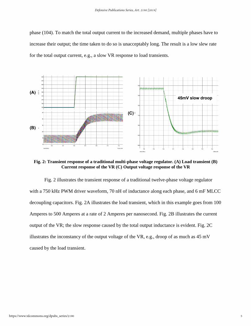
Fig. 2: Transient response of a traditional multi-phase voltage regulator. (A) Load transient (B)
Current response of the VR (C) Output voltage response of the VR
Fig. 2 illustrates the transient response of a traditional twelve-phase voltage regulator
with a 750 kHz PWM driver waveform, 70 nH of inductance along each phase, and 6 mF MLCC
decoupling capacitors. Fig. 2A illustrates the load transient, which in this example goes from 100
Amperes to 500 Amperes at a rate of 2 Amperes per nanosecond. Fig. 2B illustrates the current
output of the VR; the slow response caused by the total output inductance is evident. Fig. 2C
illustrates the inconstancy of the output voltage of the VR, e.g., droop of as much as 45 mV
caused by the load transient.
5
Defensive Publications Series, Art. 2190 [2019]
https://www.tdcommons.org/dpubs_series/2190
Page 6
DESCRIPTION
Fig. 3: Multi-phase trans-inductor voltage regulator (TLVR). (A) Single-secondary TLVR (B) Dual-
secondary TLVR
This disclosure describes a multi-phase trans-inductor voltage regulator (TLVR),
example topologies of which are illustrated in Fig. 3. Fig. 3A illustrates an N-phase single-
secondary TLVR and Fig. 3B illustrates an N-phase dual-secondary TLVR. In a similar manner,
N-phase triple-secondary, N-phase quadruple-secondary, etc., TLVRs can be defined. The TLVR
is such that each of its phases has an output inductor (302a-b) that is the secondary winding of a
transformer whose primary windings (304a-b) are all connected in a series loop. In the event of a
6
: Fast multi-phase trans-inductor voltage regulator
Published by Technical Disclosure Commons, 2019
Page 7
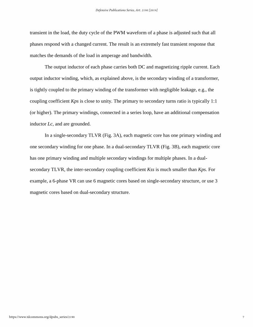
transient in the load, the duty cycle of the PWM waveform of a phase is adjusted such that all
phases respond with a changed current. The result is an extremely fast transient response that
matches the demands of the load in amperage and bandwidth.
The output inductor of each phase carries both DC and magnetizing ripple current. Each
output inductor winding, which, as explained above, is the secondary winding of a transformer,
is tightly coupled to the primary winding of the transformer with negligible leakage, e.g., the
coupling coefficient Kps is close to unity. The primary to secondary turns ratio is typically 1:1
(or higher). The primary windings, connected in a series loop, have an additional compensation
inductor Lc, and are grounded.
In a single-secondary TLVR (Fig. 3A), each magnetic core has one primary winding and
one secondary winding for one phase. In a dual-secondary TLVR (Fig. 3B), each magnetic core
has one primary winding and multiple secondary windings for multiple phases. In a dual-
secondary TLVR, the inter-secondary coupling coefficient Kss is much smaller than Kps. For
example, a 6-phase VR can use 6 magnetic cores based on single-secondary structure, or use 3
magnetic cores based on dual-secondary structure.
7
Defensive Publications Series, Art. 2190 [2019]
https://www.tdcommons.org/dpubs_series/2190
Page 8
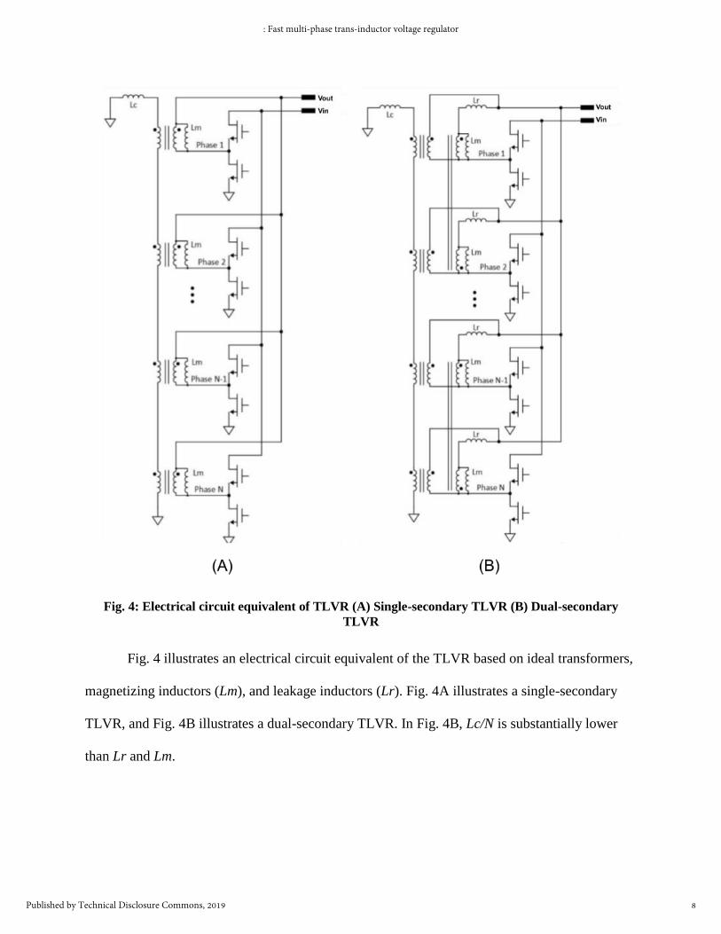
Fig. 4: Electrical circuit equivalent of TLVR (A) Single-secondary TLVR (B) Dual-secondary
TLVR
Fig. 4 illustrates an electrical circuit equivalent of the TLVR based on ideal transformers,
magnetizing inductors (Lm), and leakage inductors (Lr). Fig. 4A illustrates a single-secondary
TLVR, and Fig. 4B illustrates a dual-secondary TLVR. In Fig. 4B, Lc/N is substantially lower
than Lr and Lm.
8
: Fast multi-phase trans-inductor voltage regulator
Published by Technical Disclosure Commons, 2019
Page 9
Fig. 5: Steady-state operation of a TLVR. (A) Single-secondary TLVR (B) Driving PWM
waveforms (C) Currents through the magnetizing inductor of each phase (D) Current through the
primary windings (E) Output current of each phase
Fig. 5 illustrates steady-state, e.g., absent load transients, operation of a (single-
secondary) TLVR (Fig. 5A). Fig. 5B illustrates the PWM waveforms that drive each phase. At
steady state, the PWM waveforms of all phases are equally interleaved. Fig. 5C illustrates the
magnetizing current carried by the magnetizing inductor Lm of each phase. As shown, the
magnetizing current includes a DC bias current as well as a triangle ripple current at switching
frequency. Fig. 5D illustrates the current through the primary windings, e.g., through the
compensation inductor Lc. The current through the compensation inductor comprises a ripple
9
Defensive Publications Series, Art. 2190 [2019]
https://www.tdcommons.org/dpubs_series/2190
Page 10
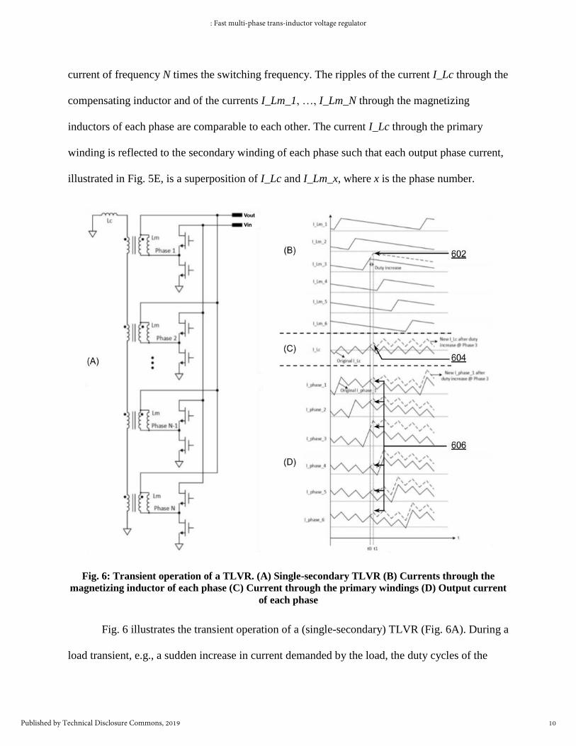
current of frequency N times the switching frequency. The ripples of the current I_Lc through the
compensating inductor and of the currents I_Lm_1, …, I_Lm_N through the magnetizing
inductors of each phase are comparable to each other. The current I_Lc through the primary
winding is reflected to the secondary winding of each phase such that each output phase current,
illustrated in Fig. 5E, is a superposition of I_Lc and I_Lm_x, where x is the phase number.
Fig. 6: Transient operation of a TLVR. (A) Single-secondary TLVR (B) Currents through the
magnetizing inductor of each phase (C) Current through the primary windings (D) Output current
of each phase
Fig. 6 illustrates the transient operation of a (single-secondary) TLVR (Fig. 6A). During a
load transient, e.g., a sudden increase in current demanded by the load, the duty cycles of the
10
: Fast multi-phase trans-inductor voltage regulator
Published by Technical Disclosure Commons, 2019
Page 11
driving PWM waveforms (not shown) are adjusted by a PWM controller. The change in PWM
duty cycle causes a change in the magnetizing current I_Lm_x (Fig. 6B) through the magnetizing
inductor (602), manifesting, e.g., as a greater amplitude to the triangle ripple waveform. In turn,
the current I_Lc (Fig. 6C) through the compensation inductor also changes (604). Since the phase
currents (Fig. 6D) are a superposition of I_Lc and I_Lm_x, all output phase currents experience a
current change (606). This results in the fast transient response of the TLVR. Effectively, the
equivalent total output inductance of the TLVR is substantially lower than traditional multi-
phase VR implementation.
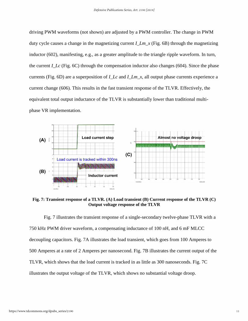
Fig. 7: Transient response of a TLVR. (A) Load transient (B) Current response of the TLVR (C)
Output voltage response of the TLVR
Fig. 7 illustrates the transient response of a single-secondary twelve-phase TLVR with a
750 kHz PWM driver waveform, a compensating inductance of 100 nH, and 6 mF MLCC
decoupling capacitors. Fig. 7A illustrates the load transient, which goes from 100 Amperes to
500 Amperes at a rate of 2 Amperes per nanosecond. Fig. 7B illustrates the current output of the
TLVR, which shows that the load current is tracked in as little as 300 nanoseconds. Fig. 7C
illustrates the output voltage of the TLVR, which shows no substantial voltage droop.
11
Defensive Publications Series, Art. 2190 [2019]
https://www.tdcommons.org/dpubs_series/2190
Page 12
Comparing Fig. 7 to Fig. 2, it is seen that the TLVR bandwidth is almost five times that of the
traditional multi-phase voltage regulator.
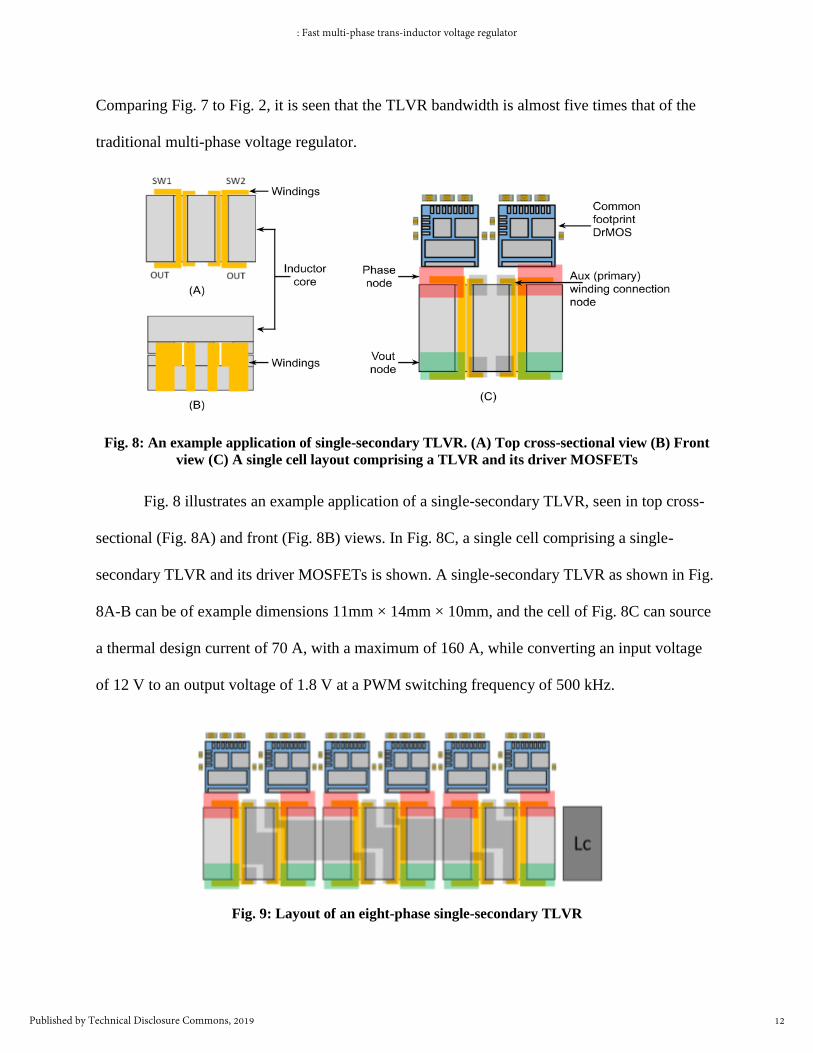
Fig. 8: An example application of single-secondary TLVR. (A) Top cross-sectional view (B) Front
view (C) A single cell layout comprising a TLVR and its driver MOSFETs
Fig. 8 illustrates an example application of a single-secondary TLVR, seen in top cross-
sectional (Fig. 8A) and front (Fig. 8B) views. In Fig. 8C, a single cell comprising a single-
secondary TLVR and its driver MOSFETs is shown. A single-secondary TLVR as shown in Fig.
8A-B can be of example dimensions 11mm × 14mm × 10mm, and the cell of Fig. 8C can source
a thermal design current of 70 A, with a maximum of 160 A, while converting an input voltage
of 12 V to an output voltage of 1.8 V at a PWM switching frequency of 500 kHz.
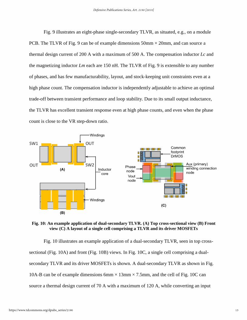
Fig. 9: Layout of an eight-phase single-secondary TLVR
12
: Fast multi-phase trans-inductor voltage regulator
Published by Technical Disclosure Commons, 2019
Page 13
Fig. 9 illustrates an eight-phase single-secondary TLVR, as situated, e.g., on a module
PCB. The TLVR of Fig. 9 can be of example dimensions 50mm × 20mm, and can source a
thermal design current of 200 A with a maximum of 500 A. The compensation inductor Lc and
the magnetizing inductor Lm each are 150 nH. The TLVR of Fig. 9 is extensible to any number
of phases, and has few manufacturability, layout, and stock-keeping unit constraints even at a
high phase count. The compensation inductor is independently adjustable to achieve an optimal
trade-off between transient performance and loop stability. Due to its small output inductance,
the TLVR has excellent transient response even at high phase counts, and even when the phase
count is close to the VR step-down ratio.
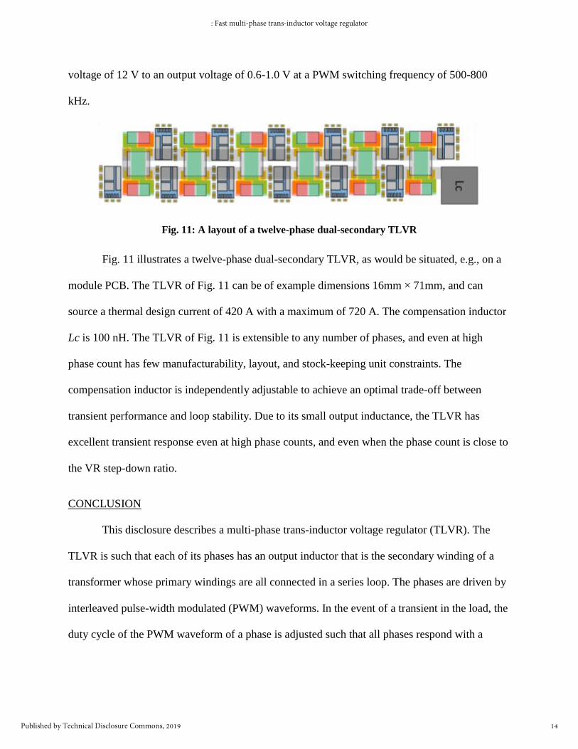
Fig. 10: An example application of dual-secondary TLVR. (A) Top cross-sectional view (B) Front
view (C) A layout of a single cell comprising a TLVR and its driver MOSFETs
Fig. 10 illustrates an example application of a dual-secondary TLVR, seen in top cross-
sectional (Fig. 10A) and front (Fig. 10B) views. In Fig. 10C, a single cell comprising a dual-
secondary TLVR and its driver MOSFETs is shown. A dual-secondary TLVR as shown in Fig.
10A-B can be of example dimensions 6mm × 13mm × 7.5mm, and the cell of Fig. 10C can
source a thermal design current of 70 A with a maximum of 120 A, while converting an input
13
Defensive Publications Series, Art. 2190 [2019]
https://www.tdcommons.org/dpubs_series/2190
Page 14
voltage of 12 V to an output voltage of 0.6-1.0 V at a PWM switching frequency of 500-800
kHz.
Fig. 11: A layout of a twelve-phase dual-secondary TLVR
Fig. 11 illustrates a twelve-phase dual-secondary TLVR, as would be situated, e.g., on a
module PCB. The TLVR of Fig. 11 can be of example dimensions 16mm × 71mm, and can
source a thermal design current of 420 A with a maximum of 720 A. The compensation inductor
Lc is 100 nH. The TLVR of Fig. 11 is extensible to any number of phases, and even at high
phase count has few manufacturability, layout, and stock-keeping unit constraints. The
compensation inductor is independently adjustable to achieve an optimal trade-off between
transient performance and loop stability. Due to its small output inductance, the TLVR has
excellent transient response even at high phase counts, and even when the phase count is close to
the VR step-down ratio.
CONCLUSION
This disclosure describes a multi-phase trans-inductor voltage regulator (TLVR). The
TLVR is such that each of its phases has an output inductor that is the secondary winding of a
transformer whose primary windings are all connected in a series loop. The phases are driven by
interleaved pulse-width modulated (PWM) waveforms. In the event of a transient in the load, the
duty cycle of the PWM waveform of a phase is adjusted such that all phases respond with a
14
: Fast multi-phase trans-inductor voltage regulator
Published by Technical Disclosure Commons, 2019
Page 15
changed current. The result is an extremely fast transient response that matches the demands of
the load in amperage and bandwidth.
15
Defensive Publications Series, Art. 2190 [2019]
https://www.tdcommons.org/dpubs_series/2190