Tenth MSU Conference on Differential Equations and Computational Simulations. Electronic Journal of Differential Equations, Conference 23 (2016), pp. 119–129. ISSN: 1072-6691. URL: http://ejde.math.txstate.edu or http://ejde.math.unt.edu ftp ejde.math.txstate.edu FAST SOLUTION OF PHASE UNWRAPPING PARTIAL DIFFERENTIAL EQUATION USING WAVELETS MARYAM RAHNEMOONFAR Abstract. Phase unwrapping is the most critical step in the processing of synthetic aperture radar interferometry. The phase obtained by SAR interfer- ometry is wrapped over a range from -π to π. Phase unwrapping must be performed to obtain the true phase. The least square approach attains the unwrapped phase by minimizing the difference between the discrete partial derivatives of the wrapped phase and the discrete partial derivatives of the unwrapped solution. The least square solution will result in discrete version of the Poisson’s partial differential equation. Solving the discretized Poisson’s equation with the classical method of Gauss-Seidel relaxation has extremely slow convergence. In this paper we have used Wavelet techniques which over- come this limitation by transforming low-frequency components of error into high frequency components which consequently can be removed quickly by using the Gauss-Seidel relaxation method. In Discrete Wavelet Transform (DWT) two operators, decomposition (analysis) and reconstruction (synthe- sis), are used. In the decomposition stage an image is separated into one low-frequency component (approximation) and three high-frequency compo- nents (details). In the reconstruction stage, the image is reconstructed by synthesizing the approximated and detail components. We tested our algo- rithm on both simulated and real data and on both unweighted and weighted forms of discretized Poisson’s equation. The experimental results show the effectiveness of the proposed method. 1. Introduction Due to the nature of SAR imaging, it does not contain information about the absolute phase of the returning radar echoes, but the phase is wrapped to the in- terval [-π,π]. Reconstruction of the absolute phase from the wrapped phase value is called phase unwrapping. Phase unwrapping is the key step in interferometric synthetic aperture radar (InSAR) processing. InSAR is a technique that uses two or more SAR images over the same area for extracting high-resolution digital ter- rain data. The technique relies on the measurement of the phase of the echoed signal rather than its amplitude, as found in conventional imaging radar system. The extreme sensitivity of the technique to altitude changes, high spatial resolu- tion and broad swath coverage makes it an extensive and accurate measurement 2010 Mathematics Subject Classification. 65T60, 35-04. Key words and phrases. Wavelets. c 2016 Texas State University. Published March 21, 2016. 119
Transcript
Tenth MSU Conference on Differential Equations and Computational Simulations.
Electronic Journal of Differential Equations, Conference 23 (2016), pp. 119–129.
ISSN: 1072-6691. URL: http://ejde.math.txstate.edu or http://ejde.math.unt.edu
ftp ejde.math.txstate.edu
FAST SOLUTION OF PHASE UNWRAPPING PARTIALDIFFERENTIAL EQUATION USING WAVELETS
MARYAM RAHNEMOONFAR
Abstract. Phase unwrapping is the most critical step in the processing of
synthetic aperture radar interferometry. The phase obtained by SAR interfer-ometry is wrapped over a range from −π to π. Phase unwrapping must be
performed to obtain the true phase. The least square approach attains theunwrapped phase by minimizing the difference between the discrete partial
derivatives of the wrapped phase and the discrete partial derivatives of the
unwrapped solution. The least square solution will result in discrete versionof the Poisson’s partial differential equation. Solving the discretized Poisson’s
equation with the classical method of Gauss-Seidel relaxation has extremely
slow convergence. In this paper we have used Wavelet techniques which over-come this limitation by transforming low-frequency components of error into
high frequency components which consequently can be removed quickly by
using the Gauss-Seidel relaxation method. In Discrete Wavelet Transform(DWT) two operators, decomposition (analysis) and reconstruction (synthe-
sis), are used. In the decomposition stage an image is separated into one
low-frequency component (approximation) and three high-frequency compo-nents (details). In the reconstruction stage, the image is reconstructed by
synthesizing the approximated and detail components. We tested our algo-
rithm on both simulated and real data and on both unweighted and weightedforms of discretized Poisson’s equation. The experimental results show the
effectiveness of the proposed method.
1. Introduction
Due to the nature of SAR imaging, it does not contain information about theabsolute phase of the returning radar echoes, but the phase is wrapped to the in-terval [−π, π]. Reconstruction of the absolute phase from the wrapped phase valueis called phase unwrapping. Phase unwrapping is the key step in interferometricsynthetic aperture radar (InSAR) processing. InSAR is a technique that uses twoor more SAR images over the same area for extracting high-resolution digital ter-rain data. The technique relies on the measurement of the phase of the echoedsignal rather than its amplitude, as found in conventional imaging radar system.The extreme sensitivity of the technique to altitude changes, high spatial resolu-tion and broad swath coverage makes it an extensive and accurate measurement
means in many fields; namely earthquake monitoring, erosion studies, and miningprospecting. The technique brings strong advantages such as independency of nat-ural illumination or recognizable targets over classical stereoscopic optical imaging.
A variety of approaches to 2-D phase unwrapping have been proposed recently.They can be classified to path-following and least-squares methods, respectively.Path-following algorithms [1, 5, 6] are based on the identification of residues, localerrors in the measured phase caused by signal noise or by actual discontinuities,and the definition of suitable branch cuts to prevent any integration path crossingthese cuts. The estimated neighboring pixel differences of unwrapped phase areintegrated along paths avoiding the branch cuts where these estimated differencesare inconsistent [5]. The problems of this approach are the definition of suitablebranch cuts and the time consuming computations.
The least-squares method is based on partial differential equation which extractsthe phase partial derivatives and then finds the unwrapped surface that best fitsthese derivatives. This technique was introduced in the late 70’s by Fried and Hud-gin [2, 7] and later refined in 1989 and 1994 by Ghiglia and Romero [3, 4]. Becausethis approach does not depend on path-following or branch-cutting techniques, it isreliable. To accelerate the convergence of solution of the phase unwrapping partialdifferential equation, direct methods based on the fast Fourier transform (FFT)[11] or the discrete cosine transform (DCT) [4] can be applied. Despite its robust-ness and speed, the technique has an inadequacy of unwrapping through phaseinconsistencies rather than unwrapping around them that causes errors in the un-wrapped surface. This problem is overcome by introducing weight functions. Inthe weighted case, direct methods cannot be used and iterative methods should beadopted. Gauss-Seidel relaxation is the classical iterative method for solving thelinear system. Due to its extremely slow convergence, Gauss-Seidel relaxation isnot a practical method but it can be base of some practical algorithms such asmultigrid [10] or wavelet [8, 12] for solving the weighted least squares phase un-wrapping. The multigrid method is an efficient algorithm to improve convergencerate. However, this method needs an additional weight restriction operator whichis very complicated and can be erroneous.
In this article, wavelet technique is used for the fast solution of phase unwrap-ping partial differential equation. Wavelet technique overcomes the limitation ofslow convergence of Gauss-Seidel relaxation by transforming low-frequency compo-nents of error into high frequency components which consequently will be removedquickly by using the Gauss-Seidel relaxation method. In Discrete Wavelet Trans-form (DWT) two operators, decomposition (analysis) and reconstruction (synthe-sis), are used. In the decomposition stage an image is separated into one low-frequency component (approximation) and three high-frequency components (de-tails). In the reconstruction stage, the image is reconstructed by synthesizing theapproximated and detail components. In this paper the proposed phase unwrappingapproach is applied both on simulated and real data. Moreover, a post-processingstep is applied to the wavelet unwrapped phase to ensure the congruency of theunwrapped phase to the wrapped phase. Another correction model is also intro-duced to remove the error - caused by atmosphere, phase and baseline - and toimprove the accuracy of the generated DEM. After this short introduction, phase
EJDE-2016/CONF/23 FAST SOLUTION 121
unwrapping concept and the proposed wavelet technique for both weighted and un-weighted least square are explained in section 2. Experimental results are presentedin section 3, Finally conclusion is drawn.
2. Phase unwrapping
The first step of a typical InSAR processing routine is the co-registration of theslave image over the master one and computation of the interferogram by multiply-ing the complex value of the master image by the complex conjugate number of thecorresponding pixel in the slave image. This Interferogram should undergo a flatearth correction, which is the removal of strong contribution due to the slant rangegeometry using the orbit data. An interferogram contains phase information whichis directly related to topography. Since this phase is given in modulo 2π, there isan ambiguity in calculating the correct integer number of 2π phase cycles that needto be added to each phase measurement in order to obtain the correct slant rangedistance. This ambiguity solution is referred to as phase unwrapping which is animportant issue in the derivation of elevations using the InSAR technique.
The problem of phase unwrapping has been the focus of InSAR research forseveral years. Numerous methods were proposed and implemented for the mostcomplex issue of the interferometric processing chain. The two major approachesare “path-following” and “least-squares” algorithms. Path-following algorithmsuse localized pixel-by-pixel operations to unwrap the phase, while least-squaresalgorithms minimize a global measure of the differences between the gradients ofthe wrapped input phase and those of the unwrapped solution. In this article,we use a wavelet algorithm for solving the two dimensional least-squares phaseunwrapping.
Let us assume that the phase of interferogram, ψi,j , which is between −π andπ is known. We want to determine the unwrapped phase value, ϕi,j , at the samegrid locations
ψi,j = ϕi,j + 2πk, (2.1)where k is an integer and −π < ψi,j < π. The least square approach attains thisunwrapped phase by minimizing the difference between the discrete partial deriva-tives of the wrapped phase and the discrete partial derivatives of the unwrappedsolution. The partial derivatives of the wrapped phase is
The values of the solution array at the boundaries are defined by the boundaryconditions
ϕ−1,j = ϕ1,j , ϕi,−1 = ϕi,1,
ϕM+1,j = ϕM−1,j , ϕi,N+1 = ϕi,N−1.(2.7)
Equation (2.5) is a discretization of the Poisson equation in a rectangular grid:
∂2
∂x2ϕ(x, y) +
∂2
∂y2ϕ(x, y) = ρ(x, y) (2.8)
Writing the above equation in matrix format yields the equation
Aϕ = ρ (2.9)
where A is a sparse matrix and ϕ is the solution of phase unwrapping. The classicalmethod for solving the discretized Poisson equation is Gauss-Seidel relaxation. Dueto its extremely slow convergence, Gauss-Seidel relaxation is not a practical method,but it is the base of the wavelet method. The Gauss-Seidel relaxation is essentially alocal smoothing operator that removes the high-frequency components of the errorvery rapidly but the low-frequency components extremely slowly. The wavelettechnique overcomes this limitation by transforming low-frequency components oferror into high-frequency components which consequently can be removed quicklyby using the Gauss-Seidel relaxation method.
2.1. Wavelet phase unwrapping. The wavelet theory allows a very general andflexible description to transform signals from a time domain to a time-frequencydomain, so-called time-scale domain. The representation is a suitable alternativeto the window Fourier transform. Wavelet transform uses short window for highfrequencies, leading to a good time resolution and larger windows for low frequenciesleading to a good frequency resolution. The one-dimensional continuous wavelettransform of a signal x(t) is defined by [9]
Wψ(a, b) =∫ +∞
−∞x(t)ψ∗a,b(t)dt
ψa,b(t) =1√|a|ψ(t− ba
)(2.10)
where ψa,b(t) stands for a given wavelet function and a and b are the scale andtranslation parameters, respectively. The wavelet transform provides the time-frequency information of a signal simultaneously. The continuous wavelet transformis computed by changing the scale of analysis window, shifting the window in time,multiplying by the signal and integrating over all the times. It is essentially ameasure of correlation between a signal and various wavelets derived from a mother.In Discrete Wavelet Transform (DWT), this is turned into a filtering operationwith a sequence of high-pass and low-pass filters of different cut-off frequencies toanalyze the signal at different scales. The signal is passed through a series of highpass filters and low pass filters. Filtering a signal corresponds to the convolution ofthe signal with impulse response of a filter. The DWT is computed as the signalsat different frequency bands with different resolutions by decomposing them intoapproximation and detail components. The decomposition is achieved at successive
EJDE-2016/CONF/23 FAST SOLUTION 123
high pass and low pass filtering of the time domain signal. The approximation anddetail components are convolved recursively with the same low-pass and high-passfilters until they reach a certain level. The discrete form of equation (2.10) can bewritten as:
caj,k[x(t)] = DS[∑
x(t) g∗j (t− 2j
k)]
cdj,k[x(t)] = DS[∑
x(t) h∗j (t− 2j
k)](2.11)
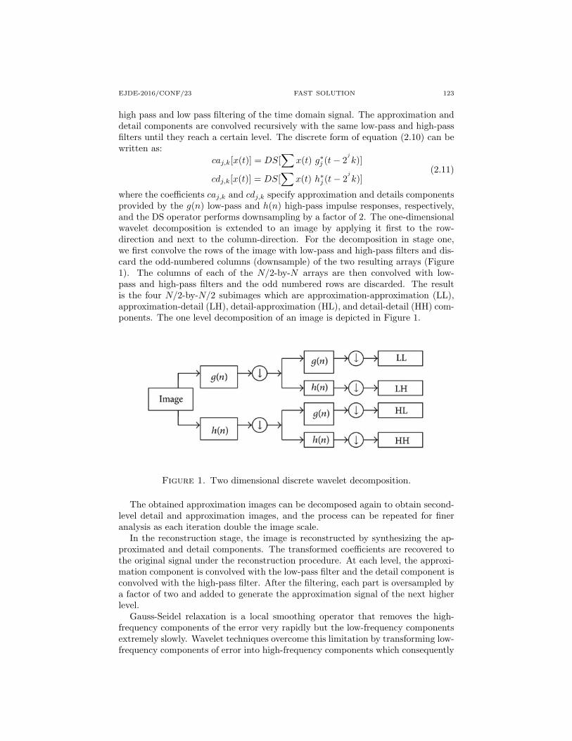
where the coefficients caj,k and cdj,k specify approximation and details componentsprovided by the g(n) low-pass and h(n) high-pass impulse responses, respectively,and the DS operator performs downsampling by a factor of 2. The one-dimensionalwavelet decomposition is extended to an image by applying it first to the row-direction and next to the column-direction. For the decomposition in stage one,we first convolve the rows of the image with low-pass and high-pass filters and dis-card the odd-numbered columns (downsample) of the two resulting arrays (Figure1). The columns of each of the N/2-by-N arrays are then convolved with low-pass and high-pass filters and the odd numbered rows are discarded. The resultis the four N/2-by-N/2 subimages which are approximation-approximation (LL),approximation-detail (LH), detail-approximation (HL), and detail-detail (HH) com-ponents. The one level decomposition of an image is depicted in Figure 1.
Figure 1. Two dimensional discrete wavelet decomposition.
The obtained approximation images can be decomposed again to obtain second-level detail and approximation images, and the process can be repeated for fineranalysis as each iteration double the image scale.
In the reconstruction stage, the image is reconstructed by synthesizing the ap-proximated and detail components. The transformed coefficients are recovered tothe original signal under the reconstruction procedure. At each level, the approxi-mation component is convolved with the low-pass filter and the detail component isconvolved with the high-pass filter. After the filtering, each part is oversampled bya factor of two and added to generate the approximation signal of the next higherlevel.
Gauss-Seidel relaxation is a local smoothing operator that removes the high-frequency components of the error very rapidly but the low-frequency componentsextremely slowly. Wavelet techniques overcome this limitation by transforming low-frequency components of error into high-frequency components which consequently
124 M. RAHNEMOONFAR EJDE-2016/CONF/23
can be removed quickly by using the Gauss-Seidel relaxation method. For solvingequation (2.9) by wavelet algorithm, after relaxing v1 times on the equation (2.9)with the initial guess 0, the residual error of this equation is transformed by thedecomposition step of the DWT into the second level. Then, further relaxation isperformed on the residual equation Ae = r in the low-frequency component (LL)of the second level with the initial guess e = 0, where r = ρ − Aϕ̂ is the knownresidual error. The resulting solution of the lower component of the coarser gridis regarded as an intermediate solution whose residual error is transformed to thethird level with DWT. This process continues until we reach the coarsest grid. Atthis point the solution is then transferred to the finer grid by the reconstructionanalysis of DWT; ultimately, it will be added to the approximation ϕ̂. This processyields a better solution on the finer grid.
2.2. Weighted wavelet phase unwrapping. The weighted least square approachattains the unwrapped phase by minimizing the difference between the discrete par-tial derivatives of the wrapped phase and the discrete partial derivatives of the un-wrapped solution. The solution ϕi,j that minimizes L is the weighted least squaresolution, where L is
L =∑i
∑j
wxi,j(ϕi,j − ϕi−1,j −∆xi,j)2
+∑i
∑j
wyi,j(ϕi,j − ϕi,j−1 −∆yi,j)2
(2.12)
where wx and wy are weight functions and ∆x and ∆y are the partial derivativesof the wrapped phase:
∆xi,j = W{ψi+1,j − ψi,j}∆yi,j = W{ψi,j+1 − ψi,j}
(2.13)
where W is the wrapping operator. The least squares solution of (2.12) yields theequation
Equation (2.14) is a weighted and discrete version of the Poisson’s partial differentialequation (PDE) which in matrix format yields the equation
Bϕ = ρ (2.16)
where B is a sparse matrix and ϕ is the solution of phase unwrapping.As it can be seen from equation(2.16), the weight array is embedded in the matrix
B, and the wavelet decomposition of B conducts the decomposition of the weightarray simultaneously. Therefore, the reduction of the weight array to a smallerscale is accomplished automatically and the separate weight reduction operationis not required. Therefore solving this equation with wavelet transform is similarto unweighted case. Because the least-squares solution minimizes the squares ofthe differences between the gradients of the solution and the phase, the solutionsare not congruent to the wrapped phase [10]. Therefore, after solving equation(2.16) with a wavelet algorithm, it is necessary to perform a post-processing step
EJDE-2016/CONF/23 FAST SOLUTION 125
by subtracting the solution from the wrapped input phase, rewrapping the result,and then adding it back into the solution.
3. Experimental results
In this section we present the results of wavelet algorithm on several datasetincluding simulated data, SAR interferometry and differential SAR interferometry.
3.1. Simulated Data. In the first example, the phase pattern of pixels is simulatedas shown in figure 2(a). Then the phase was wrapped to the interval of −π to π(figure 2(b)). To evaluate the performance of the proposed method, we unwrappedthe phase using wavelet technique and then compared it with the Gauss-Seidel,and multigrid[10] methods. The reconstructed phase pattern via Gauss-Seidel,multigrid and wavelet method with the same number of iterations (100 iterations)are shown in 2(a). Comparing the results with the original shape (figure 2(a)), weachieved the average of 2.88 and 2.10 differences (error) for multigrid and waveletmethods, respectively. This shows that the wavelet method is more accurate thanthe multigrid and it converges faster.
In other experiment a terrain model is generated with fractal (figure 3(a)). Thephase is wrapped to the interval of −π to π to simulate the interferogram (Figure3(b)). In this case a weighted wavelet and multigrid method is used. Figures 3(c)and 3(d) show the weights in x and y direction. Weights are extracted by varianceof phase derivatives in x any y direction. Figure 3(e) shows the reconstructed phasepattern of wavelet method. In this case the RMS error for wavelets is 0.62 whileit is 0.66 for multigrid that shows a better solution of wavelet in weighted case. Itis explained in previous section that the least squares solutions are not congruentto the wrapped input phase, so a post-processing step was done on two results.The RMS errors after the post-processing step are 0.13 and 0.24 for wavelet andmultigrid, respectively.
3.2. Real data. In the second part of the experimental results, the proposedmethod was tested on some real data. In the first part, two single look complexSAR images of ENVISAT ASAR data are used to generate Digital Elevation Model(DEM). In the second part three single look complex SAR images of ENVISATASAR data are used to create differential interferogram to study earthquake.
3.3. Digital elevation model. SAR Interferometry is based on the measurementof phase differences caused by a path difference, in the slant range direction, of theradar signal. A path difference, and consequently an interferometric pattern, canbe caused by a slight change in the angle under which the same terrain is seen inthe two images (Figure 4). By considering images taken from the sensor at twoslightly different positions we can deduce the height of the terrain. This approachof InSAR is used to produce Digital Elevation Models (or DEM’s) of the surface.The phase fringes, obtained in this way after phase unwarpping stage, are directlyrelated to the terrain height.
In this experiment, two single look complex SAR images of ENVISAT ASARdata were used for creating DEM. After co-registration of two images and creat-ing interferogram, the filtered interferograms were unwrapped using the weightedwavelet algorithm. The coherence map of the area is used for weight function.Coherence map is created based on the correlation between two images. For both
126 M. RAHNEMOONFAR EJDE-2016/CONF/23
(a) Original function (b) Wrap Function
Figure 2. 2(a) Simulated phase pattern, 2(b) wrapped phase,2(c) unwrapped phase with Gauss-Seidel method, 2(d) unwrappedphase with multigrid, 2(e) unwrapped phase with wavelet.
x and y directions, the same weight function is applied. After the phase unwrap-ping step by weighted wavelet algorithm, the post-processing step is also performedto achieve congruence between the unwrapped phase and the wrapped phase. Inorder to construct the DEM, the unwrapped phases were converted to height andthen geocoded. To evaluate the results, the DEM generated as the result of In-SAR processing was compared with a DEM generated from a 1/25000 scale map.The evaluation was performed in two regions of the Kerman province, Fahraj andNosratabad, due to reference DEM availability in these two regions. The averageamount of height difference between the DEM produced by SAR Interferometryand the reference DEM was 3.05 and 2.60 meter for Fahraj and Nosratabbad, re-spectively. Our results are in good agreement with the reported accuracy for InSAR
EJDE-2016/CONF/23 FAST SOLUTION 127
Figure 3. 3(a) Simulated phase pattern with fractal, 3(b)wrapped phase, 3(c) weights in x direction, 3(d) weights in y direc-tion, 3(e) unwrapped phase with weighted wavelet phase unwrap-ping.
method which is between 3 to 20 meters. The reason for better accuracy in Nos-rataabad is due to higher coherency in that region.
3.4. SAR differential interferometry. To detect the land deformation causedby earthquake, volcano or landslide, it is necessary to compare two images of thesame area which are taken exactly from the same position in two different times. Inpractice, however it is highly improbable that the sensor will return exactly to thesame position twice and the baseline will always be different from zero. This causesthe presence of a topographic component in the measured interferometric phase,which adds up to the deformation information. The topographic contribution canbe separated and subtracted from the deformation by using the so-called differentialtechnique. A second interferogram is generated with two images taken over a timeinterval during which no significant deformation had occurred. This interferogram,
128 M. RAHNEMOONFAR EJDE-2016/CONF/23
Figure 4. SAR interferometry for DEM generation.
which will thus contain only topographic information, is re-scaled and subtractedfrom the one of interest, leaving in this latter only the deformation signal.
In this experiment three single look complex SAR images of ENVISAT ASARdata were used. Two images were taken before earthquake and one image afterearthquake. Figure 5 shows the differential interferogram.
Figure 5. Differential interferogram obtained from three SAR images.
EJDE-2016/CONF/23 FAST SOLUTION 129
The magnitude of the earthquake calculated using the differential SAR interfer-ometry was 6.4 which is in very good agreement with ground-based measurementsshowing the magnitude of 6.5.
Conclusion. An effective method to solve the phase unwrapping partial differ-ential equation based on the wavelet approach has been discussed. The Waveletapproach overcomes the low convergence rate of Gauss-Seidel relaxation method bytransforming low-frequency components of error into high frequency components.By decomposing an image into one low-frequency component (approximation) andthree high-frequency components (details) and solving the low-frequency portion ofthe new system, it speeds up the overall system convergence rate. The proposedalgorithm was tested on both simulated and real data; and they shows better resultthan Gauss-Seidel relaxation and the multigrid methods. Since the new transformedsystem is mathematically equivalent to the original matrix both for the weightedand unweighted least squares phase unwrapping, its solution is exact to the originalequation.
References
[1] T. J. Flynn; Two-dimensional phase unwrapping with minimum weighted discontinuity,
JOSA A, 14 (1997), pp. 2692–2701.
[2] D. L. Fried; Least-square fitting a wave-front distortion estimate to an array of phase-difference measurements, JOSA, 67 (1977), pp. 370–375.
[3] D. C. Ghiglia, L. A. Romero; Direct phase estimation from phase differences using fast elliptic
partial differential equation solvers, Optics letters, 14 (1989), pp. 1107–1109.[4] D. C. Ghiglia, L. A. Romero; Robust two-dimensional weighted and unweighted phase un-
wrapping that uses fast transforms and iterative methods, JOSA A, 11 (1994), pp. 107–117.
[5] R. M. Goldstein, H. A. Zebker, C. L. Werner; Satellite radar interferometry: Two-dimensional phase unwrapping, Radio Science, 23 (1988), pp. 713–720.
[6] I. Gurov and M. Volkov; Fringe evaluation and phase unwrapping of complicated fringe
patterns by the data-dependent fringe processing method, Instrumentation and Measurement,IEEE Transactions on, 55 (2006), pp. 1634–1640.
[7] R. H. Hudgin; Wave-front reconstruction for compensated imaging, JOSA, 67 (1977), pp. 375–378.
[8] S. B. Kim, Y. S. Kim; Least squares phase unwrapping in wavelet domain, IEE Proceedings-
Vision, Image and Signal Processing, 152 (2005), pp. 261–267.[9] Y. Meyer; Wavelets and operators, vol. 1, Cambridge university press, 1995.
[10] M. D. Pritt; Phase unwrapping by means of multigrid techniques for interferometric sar,
Geoscience and Remote Sensing, IEEE Transactions on, 34 (1996), pp. 728–738.[11] M. D. Pritt, J. S. Shipman; Least-squares two-dimensional phase unwrapping using fft’s,
Geoscience and Remote Sensing, IEEE Transactions on, 32 (1994), pp. 706–708.
[12] M. Rahnemoonfar, B. Plale; Dem generation with sar interferometry based on weightedwavelet phase unwrapping, in Computing for Geospatial Research and Application (COM.
Geo), 2013 Fourth International Conference on, IEEE, 2013, pp. 87–91.
Maryam RahnemoonfarDepartment of Computer Science, Texas A&M University-Corpus Christi, 6300 OceanDr., Corpus Christi, TX 78412, USA