Executive Summary RP 930-307
FATIGUE OF DIAPHRAGM-GIRDER CONNECTIONS
Sponsored by
The Alabama Department of Transportation Montgomery, Alabama
Higftway Research Center Harbert Engineering Center
Presented by
J. Michael Stallings Thomas E. Cousins
J. W. Tedesco
~Ubum 9AiverslJY.. Alabama 36849-5337
April 1996
TECHNICAL REPORT STANDARD TITLE PAGE
1. Report No. 2. Government Accession No. 3. Recipient's Catalog No.
4. Title and Subtitle 5. Report Date
Fatigue of Diaphragm-Girder Connections April 1996
6. Performing Organization Code
7. Author(s) Stallings, J. Michael, Cousins, Thomas E., Tedesco, J. W. 8. Performing Organization Report No.
9. Performing Organization Name and Address 10. Work Unit No. Auburn University Highway Research Center 11. Contract or Grant No. 238 Harbert Engineering Center 930-307 Auburn, AL 36849-5337
13. Type of Report and Period Covered
12. Sponsoring Agency Name and Address Executive Summary Alabama Department of Transportation Research and Development Bureau 1409 Coliseum Boulevard 14. Sponsoring Agency Code
Montgomery, AL 36130-3050
15. Supplementary Notes ,
16. Abstract
Distortion-induced fatigue cracking has occurred at hundreds of diaphragm-girder connections in multi-girder steel bridges in Birmingham, Alabama in recent years. The research goal was an improved maintenance strategy for repair and maintenance of the bridges so the potential for future cracking is minimized. The investigation included field measurements of distortion-induced stresses at connections, field measurements of the effects of removing diaphragms from two in-service bridges, structural evaluations of typical bridge designs, Finite Element Method analyses of typical bridge designs, and laboratory testing of bolted connections.
Results indicate interior diaphragms can be removed from many existing bridges without significant negative effects. Guidelines for evaluating candidate bridges were developed for both simple spans and continuous spans. A bolted connection was designed, installed in the field, and tested. Tests confirmed the new design performed better than the original design.
17. Key Words 18. Distribution Statement
Bridges, fatigue, tests, diaphragms, load distribution No Restriction
19. Security Classif. (of this report) 20. Security Classif. (of this page) 21. No. of Pages 22. Price
None None 16
Form DOT F 1700.7 (8-69)
ACKNOWLEDGEMENT
The material contained herein was obtained or developed in connection with a research project, "Fatigue of Diaphragm-Girder Connections," RP 930-307, conducted by the Highway Research Center at Auburn University. The research project was sponsored by the Alabama Department of Transportation (ALDOT) and the Federal Highway Administration (FHWA). Traffic control, bridge inspection vehicles, test load vehicles and operators for the field testing, and manpower and equipment for removal of diaphragms from existing bridges were provided by the Alabama Department of Transportation Maintenance Bureau and Third Division. Fatigue testing equipment was purchased with funding from the sponsors. The support, interest, cooperation, and assistance of many personnel from ALDOT and FHWA is gratefully acknowledged. Much work by graduate students Matthew D. Bell, Daniel G. Davis, David A. Lower, Nathan M. Porter, Thomas E. Stafford, and Dennis Tow is gratefully acknowledged.
DISCLAIMER
The contents of this report reflect the views of the authors who are responsible for the facts and accuracy of the data presented herein. The contents do not necessarily reflect the official views or policies of the Alabama Department of Transportation or Auburn University. The report does not constitute a standard, specification, or regulation.
Executive Summary
FATIGUE OF DIAPHRAGM-GIRDER CONNECTIONS
by
J. Michael Stallings Thomas E. Cousins
J. W. Tedesco
sponsored by
The Alabama Department of Transportation Montgomery, Alabama
April 1996
SUMMARY
Construction of the interstate highway system through downtown Birmingham
began in the late 1960's, and multi-girder steel bridges were used extensively. In most
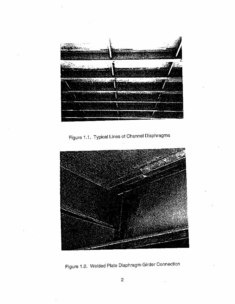
bridges, rolled W-shapes were used for girders and rolled channels for the diaphragms.
The diaphragm-girder connections were typically made of a flat plate shop welded to
the girder web and field welded to the diaphragm. The diaphragm connection plates
were not attached to the girder flanges because welding to a tension flange was
discouraged in common design practice at that time.
Over the last six years bridge inspectors have discovered distortion-induced
fatigue cracks in the welds, connection plates, diaphragms, and girder webs at
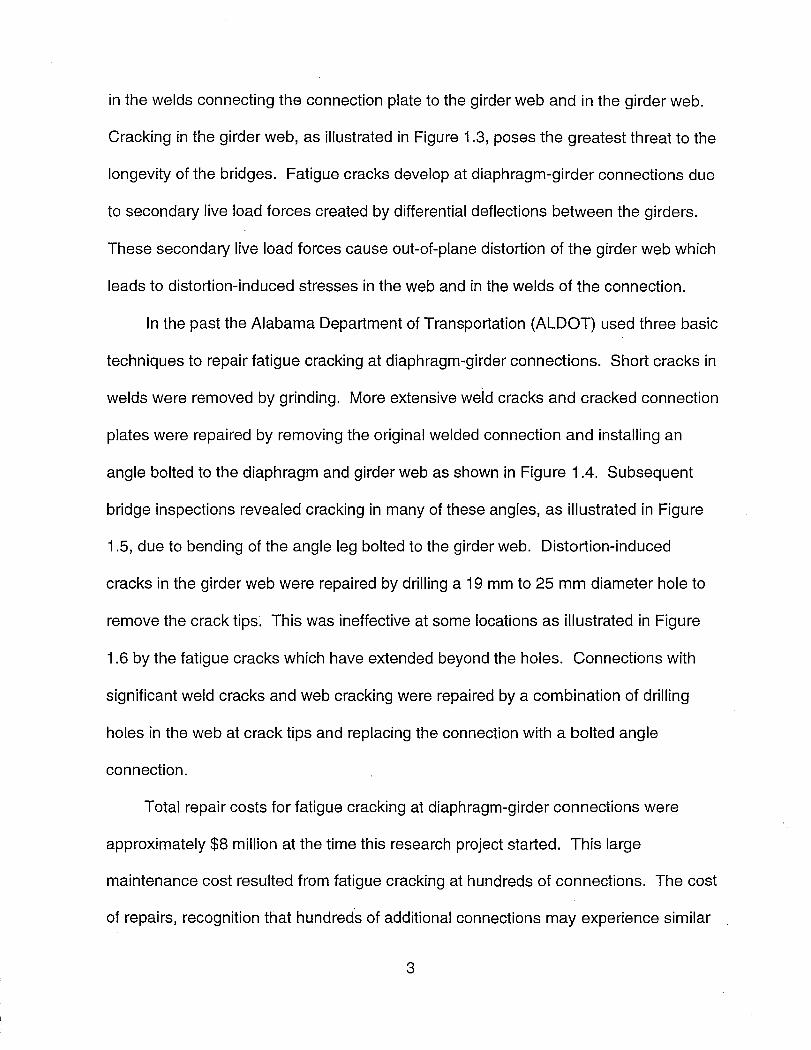
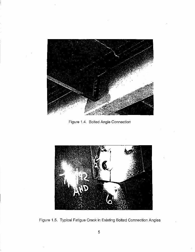
hundreds of the diaphragm-girder connections in the Birmingham bridges. Repairs
included removing cracked welds, drilling holes at crack tips, and replacing welded
connections with a bolted angle connection. Subsequent bridge inspections revealed
that holes drilled at crack tips were ineffective at some connections and fatigue cracks
had initiated in many of the bolted connection angles after only two years in-service.
The project goal was to develop an improved maintenance strategy for repairing
diaphragm-girder connections and maintaining the bridges so that the potential for
future cracking is minimized. The following options were investigated: continued use of
holes drilled at the tips of web cracks, removal of interior diaphragms to eliminate
diaphragm-girder connections, and redesign of the bolted connection angle to improve
the fatigue life. The investigations included field measurements of distortion-induced
stresses at connections, field measurements of the effects of removing diaphragms from
two in-service bridges, structural evaluations of typical bridge designs, Finite Element
ii
Method analyses of typical bridge designs to evaluate the effects of removing
diaphragms, and laboratory testing of bolted diaphragm-girder connections.
Results of the research indicate interior diaphragms can be removed from
existing bridges without significant negative effects. Guidelines for evaluating candidate
bridges were developed for both simple spans and continuous spans. Evaluations of
five typical designs were performed which indicate that all interior diaphragms can be
remove from the (two) simple span bridges investigated and approximately half the
interior diaphragms can be removed from the (three) continuous span bridges
investigated.
The cause of the fatigue cracking in the original bolted connection angles used in
repairs was identified, and a new design was developed. Laboratory tests and field
measurements confirmed that the fatigue performance of the new design was better
than that of the original design. The new design is proposed for use at connections
where diaphragms are not removed.
iii
TABLE OF CONTENTS OF FINAL REPORT
List of Figures .................................................. vii
List of Tables .................................................. xiv
CHAPTER ONE: INTRODUCTION.................................. 1 BACKGROUND ........................................... 1 PROJECT OBJECTIVES .................... . . . . . . . . . . . . . . .. 6
Holes Drilled at Crack Tips ............................. 7 Diaphragm Removal ............ _ ...................... 7 Relocation of Diaphragms and Redesign of Bolted . . . . . . . . . .. 8
Connections
CHAPTER TWO: FIELD EVALUATION OF FATIGUE CRACKING ........ 13 INTRODUCTION •........................................ 13 BRIDGE DESCRIPTIONS .................................. 14 DIAPHRAGM-GIRDER CONNECTION DESCRIPTIONS .......... 22 CONNECTION WEB GAP LENGTHS ......................... 24 INSTRUMENTATION AND DATA ACQUISITION ................ 28 Instrumentation . . . . . . . . . . . . . . . . . . . . . . . . . . . . . . . . . . . . . . . . . .. 28 Data Acquisition System ................................... 36 Calibration Tests. . . . . . . . . . . . . . . . . . . . . . . . . . . . . . . . . . . . . . . . .. 37 Traffic Tests ............................................. 39
Data Reduction ..................................... 4.0 Effective Stress Range .................................... 41 TEST RESULTS, BEHAVIOR AND ANALYSIS . . . . . . . . . . . . . . . . .. 42 Methodology for Evaluating Field Measurements ................ 43 Fatigue Categories for Critical Locations in Web Gap ............. 44 Analysis of Web Gap Stress Range Results .................... 45
Type A Welded Plate Connection ....................... 49 Type B Welded Plate Connection ......... ~ . . . . . . . . . . . .. 51 Type C Welded Angle Connection. . . . . . . . . . . . . . . . . . . . . .. 52 Type D Bolted Angle Connection . . . . . . . . . . . . . . . . . . . . . . .. 52 Type E Bolted Angle Connection . . . . . . . . . . . . . . . . . . . . . . .. 54 Type F Bolted Angle Connection . . . . . . . . . . . . . . . . . . .. . . .. 56 Type G Bolted Angle Connection ....................... 56
BEHAVIOR OF BOLTED CONNECTION ANGLES. . . . . . . . . . . . . .. 57 Type DAngle . . . . . . . . . . . . . . . . . . . . . . . . . . . . . . . . . . . . . .. 59 Type E Angle . . . . . . . . . . . . . . . . . . . . . . . . . . . . . . . . . . . . . .. 61 Type F Angle .......................... . . . . . . . . . . . .. 62 Type G Angle ....................................... 62 Effectiveness of the Hole Drilling Retrofit Technique. . . . . . . .. 62 Discussion of the Bolted Connection Results .............. 64
iv
Overall Comparison of the Bolted Web Gap and Angle . . . . . .. 64 Results
EFFECTS OF STAGGERED DIAPHRAGMS. . . . . . . . . . . . . . . . . . .. 65 CONCLUSIONS . . . . . . . . . . . . . . . . . . . . . . . . . . . . . . . . . . . . . . . . .. 65
CHAPTER THREE: LABORATORY INVESTIGATION OF BOLTED . ... . . .. 68 CONNECTIONS INTRODUCTION ......................................... 68 TEST SPECIMEN AND TEST DESIGN . . . . . . . . . . . . . . . . . . . . . . .. 70
Connection Angle Sizes. . . . . . . . . . . . . . . . . . . . . . . . . . . . . .. 70 Laboratory Model Description .......................... 73 Loading Method . . . . . . . . . . . . . . . . . . . . . . . . . . . . . . . . . . . .. 78 Instrumentation ..................................... 79 Data Acquisition . . . . . . . . . . . . . . . . . . . . . . . . . . . . . . . . . . . .. 86
ANALYSIS AND DISCUSSION OF RESULTS. . . . . . . . . . . . . . . . . .. 87 Bolted Angle Behavior . . . . . . . . . . . . . . . . . . . . . . . . . . . . . . .. 87 Fatigue Test Results ................................. 93 Comparison of Performance of Connection Angle Types ..... 98 Flexibility of Bolted Angle Connections .................. 100 Fatigue Performance of Connection Angles .............. 103 Web Gap Behavior ................................. 108 Effect of Connection Angle Type on Web Gap Flexibility .... 109 Fatigue Performance of Web Gaps . . . . . . . . . . . . . . . . . . . .. 111
CONCLUSIONS . . . . . . . . . . . . . . . . . . . . . . . . . . . . . . . . . . . . . . . .. 111
CHAPTER FOUR: STRUCTURAL EVALUATIONS ................... 116 INTRODUCTION ........................................ 116 THEORETICAL BACKGROUND: LATERAL TORSIONAL. . . . . . .. 118
BUCKLING LATERAL TORSIONAL BUCKLING ANALYSES ............... , 127
Results of the L TB Analyses .......................... 129 RATING ANALYSES ..................................... 138 WIND LOAD ANALYSIS ................................... 142 TEMPORARY BRACING REQUIREMENTS ................... 147 CONCLUSIONS ............................... , . . . . . . . .. 148
CHAPTER FIVE: EFFECTS OF REMOVING DIAPHRAGMS FROM A .... 150 24.5 METER COMPOSITE SIMPLE SPAN INTRODUCTION ........................................ 150 BRIDGE DESCRIPTION .................................. 150 INSTRUMENTATION AND DATA ACQUISITION ............... 152 DESCRIPTION OF FIELD TESTS . . . . . . . . . . . . . . . . . . . . . . . . . .. 158
Calibration Tests ................................... 158 Normal Traffic Tests. . . . . . . . . . . . . . . . . . . . . . . . . . . . . . . .. 159
CALIBRATION TESTS RESULTS ........................... 161'
v
Comparisons with Calculated Stresses .. . . . . . . . . . . . . . . .. 167 NORMAL TRAFFIC TESTS RESULTS ....................... 170 AASHTO WHEEL LOAD DISTRIBUTION FACTORS AND . . . . . . .. 183
CALCULATED WHEEL LOAD DISTRIBUTION FACTORS CONCLUSIONS . . . . . . . . . . . . . . . . . . . . . . . . . . . . . . . . . . . . . . . .. 185
CHAPTER SIX: EFFECTS OF REMOVING DIAPHRAGMS FROM A ..... 186 76 METER 3 SPAN CONTINUOUS BRIDGE INTRODUCTION ..................................... '. .. 186 BRIDGE DESCRIPTION .................................. 186 INSTRUMENTATION AND DATA ACQUISITION ............... 191 DESCRIPTION OF FIELD TESTS ........................... 193 CALIBRATION TESTS RESULTS ........................... 193 COMPARISON WITH CALCULATED STRESSES .............. 206 NORMAL TRAFFIC TESTS RESULTS ....................... 209 CONCLUSIONS . . . . . . . . . . . . . . . . . . . . . . . . . . . . . . . . . . . . . . . .. 224
CHAPTER SEVEN: ANALYTICAL EVALUATION OF REMOVING. . . . . . .. 226 DIAPHRAGMS INTRODUCTION ........................................ 226 FINITE ELEMENTS MODELS .............................. 226 STATIC FEM ANALYSES ................................. 235 SIMPLE SPAN BRIDGES ................................. 236 SKEWED SIMPLE SPANS ................................ , 241 CONTINUOUS SPAN BRIDGES ............................ 246 CONCLUSIONS . . . . . . . . . . . . . . . . . . . . . . . . . . . . . . . . . . . . . . . .. 257
CHAPTER EIGHT: CONCLUSIONS AND RECOMMENDATIONS ........ 258 CONCLUSIONS . . . . . . . . . . . . . . . . . . . . . . . . . . . . . . . . . . . . . . . .. 258 RECOMMENDATIONS ................................... 260
REFERENCES. . . . . . . . . . . . . . . . . . . . . . . . . . . . . . . . . . . . . . . . . . . . . . .. 262 APPENDICES ................................................ 266
APPENDIX A: NON-COMPOSITE BRIDGE ANALYSIS. . . . . . . . .. 267 APPENDIX B: COMPOSITE BRIDGE ANALYSIS . . . . . . . . . . . . . .. 284 APPENDIX C: NON-COMPOSITE BRIDGE ANALYSIS .......... 302
vi
BACKGROUND
Multi-girder steel bridges are common along the state and interstate highway
systems throughout the United States. The steel girders span in the direction of traffic
flow from bent to bent and serve as the primary load carrying members. The structural
system is tied together by a reinforced concrete deck slab and transverses steel
members, or diaphragms, that are connected to the girders. Diaphragms at the girder
supports provide resistance to transverse traffic and wind loadings.' Interior
diaphragms stabilize the girders during construction and placement of the deck, and
also serve to some extent to distribute traffic loads transversely among the girders.
Construction of the interstate highway system through downtown Birmingham
began in the late 1960's, and multi-girder steel bridges were used extensively.
Primarily rolled W-shapes were used for girders and rolled channels for the
diaphragms as shown in Figure 1.1. The diaphragm-girder connection in the original
construction typically consisted of a plate field welded to the channel diaphragm and
shop welded to the girder web. A typical connection is shown in Figure 1.2. Some
connections were made using an angle welded to the girder web instead of a flat plate.
The diaphragm connection plates were not attached to the girder flanges because
welding to a tension flange was discouraged in common design guides at that time.
Over the last six years bridge inspectors have discovered fatigue cracking in the
welds and base metal in many of the welded diaphragm-girder connections. Cracks
have been discovered in the welds connecting the diaphragm to the connection plate,
1
Figure 1.1. Typical Lines of Channel Diaphragms
Figure 1.2. Welded" Plate Diaphragm-Girder Connection
2
in the welds connecting the connection plate to the girder web and in the girder web.
Cracking in the girder web, as illustrated in Figure 1.3, poses the greatest threat to the
longevity of the bridges. Fatigue cracks develop at diaphragm-girder connections due
to secondary live load forces created by differential deflections between the girders.
These secondary live load forces cause out-of-plane distortion of the girder web which
leads to distortion-induced stresses in the web and in the welds of the connection.
In the past the Alabama Department of Transportation (ALDOT) used three basic
techniques to repair fatigue cracking at diaphragm-girder connections. Short cracks in
welds were removed by grinding. More extensive weld cracks and cracked connection
plates were repaired by removing the original welded connection and installing an
angle bolted to the diaphragm and girder web as shown in Figure 1.4. Subsequent
bridge inspections revealed cracking in many of these angles, as illustrated in Figure
1.5, due to bending of the angle leg bolted to the girder web. Distortion-induced
cracks in the girder web were repaired by drilling a 19 mm to 25 mm diameter hole to
remove the crack tips~ This was ineffective at some locations as illustrated in Figure
1.6 by the fatigue cracks which have extended beyond the holes. Connections with
significant weld cracks and web cracking were repaired by a combination of drilling
holes in the web at crack tips and replacing the connection with a bolted angle
connection.
Total repair costs for fatigue cracking at diaphragm-girder connections were
approximately $8 million at the time this research project started. This large
maintenance cost resulted from fatigue cracking at hundreds of connections. The cost
of repairs, recognition that hundreds of additional connections may experience similar
3
Bottom of Top Flange ~
Radius
Fatigue cracks 20-50mm in length at toe of welds
Radius
Bottom Flange
"""" Fatigue cracks up to 125mm in web close to web-flange radius
Fatigue cracks in web propagating from weld up to 125mm long
Connection Plate
Figure 1.3. Typical Web Gap Cracks
4
Figure 1.4. Bolted Angle Connection
Figure 1.5. Typical Fatigue Crack in Existing Bolted Connection Angles
5
Figure 1.6. Web Cracks at Welded Plate Connection with Drilled Hole Repair
problems, and concern that the repairs being performed were not permanent provided
motivation for this research.
PROJECT OBJECTIVES
The overall goal of this project was to develop a maintenance strategy for
repairing fatigue cracking at diaphragm-girder connections and maintaining the bridges
so that the potential for future fatigue cracking is minimized. Specific objectives were
. to investigate the following maintenance options: complete or partial removal of interior
diaphragms, continued use of hole drilling to repair web cracks, and relocation and/or
redesign of bolted connection angles. A description of the options is given below
along with the methodology used to evaluate each one.
6
Holes Drilled at Crack Tips
Past laboratory tests by Fisher et al. (1990) indicate that drilling a hole at the tip
of a distortion-induced fatigue crack is an effective repair under certain stress
conditions. Inspections of bridges in Birmingham just prior to the start of this project
revealed cracks propagating beyond the holes at approximately five percent of the
connections where holes were drilled. This could result from missing the crack tip
when the hole was drilled or from re-initiation of the crack as a result of very high
distortion-induced stresses. One objective of this project was to use field
measurements of stresses at several connections to evaluate the potential for
successful permanent arrest of distortion-induced web cracks. The evaluation was
performed using field measurements of distortion-induced stresses at 13 different
welded connections in various bridges around the Birmingham area.
Diaphragm Removal
Diaphragms have been required in multi-girder steel bridges at a spacing no
greater than 7.6 m since 1944 by the American Association of State Highway and
Transportation Officials' Standard Specifications for Highway Bridges (1944). The
7.6 m limit was apparently an arbitrary limit which was possibly based on construction
requirements. Early experts such as Newmark (1948) recognized that diaphragms had
. only a small effect on the performance of a bridge after the concrete deck was
completed.
The goal here is to identify conditions where diaphragms can be removed from
existing bridges to eliminate diaphragm-girder connections where fatigue cracking is a
problem. By eliminating the connection, the fatigue problem is solved.
7
Several parallel efforts were undertaken to investigate the effects of diaphragm
removal. Structural evaluations were performed for five typical bridges. These
evaluations included a load rating analysis, wind load analysis, and a lateral-torsional
buckling analysis for continuous span bridges. The results of the evaluations illustrate
the effects of diaphragm removal with standard engineering calculations. The
structural evaluations provide a methodology for evaluating other bridges where
diaphragm removal is desirable and provide example calculations.
Effects of diaphragm removal were also investigated by field tests. Load tests
were performed on two bridges, a long simple span and a three span continuous
bridge, before and after all the interior diaphragms were removed. To extend the
investigation beyond the practical limits of field tests, Finite Element Method (FEM)
analyses were performed on eight bridges which cover a wide range of typical bridge
geometries.
Relocation of Diaphragms and Redesign of Bolted Connections
The possibility that complete diaphragm removal may not be feasible for all
bridges was recognized before the project began. Results early in the project
illustrated that complete removal was not always possible. Logical alternatives include
moving the diaphragms to locations where the potential for cracking is minimized and
redesigning the connections to improve the fatigue life. Trade-offs between the costs
of moving lines of diaphragms and expected improvements in the fatigue life of
proposed new connections narrowed the focus of the research to improving the
performance of bolted diaphragm-girder connections.
8
Field observation of numerous cracked connection angles, such as the one
shown in Figure 1.5, indicated that the fatigue crack initiated at the outside surface of
the angle in front of the bottom bolt. Fatigue cracks were observed to initiate at the
edge of an indentation created by the nut or bolt head during tightening as shown in
Figure 1.7, or a short distance in front of the bolt as shown in Figure 1.8. The fatigue
crack propagated inward and lengthwise along the angle as illustrated by the shape of
the fatigue crack in Figure 1.8. The inward crack propagation resulted from a tensile
bending stress at the outside face of the angle caused by the diaphragm pushing on
the bottom of the angle. Subsequent field and laboratory test data confirm this
conclusion and show this is possible due to the existence of a gap between the inside
face of the angle and the girder web as shown in Figure 1.9. The width, or size, of the
gap limits how much the diaphragm can push the angle to close the gap, and places a·
limit on the maximum possible magnitude of the tensile stress range which causes
fatigue cracking.
A truck crossing a bridge can cause the diaphragm to push or pull on the bottom
of a connection angle based on where the connection is relative to the loaded traffic
lane. Generally, all connections undergo some pushing and pulling from truck traffic
distributed among the traffic lanes. Field measurements of stresses in angles of the
original design show that very heavy trucks pull (or pry) on the bottom of the angle
sufficiently to cause yielding in front of the bottom bolt. This yielding results in a
permanent increase in the width of the gap between the angle leg and the girder web
which accelerates fatigue crack initiation.
9
Figure 1.7. Fatigue Crack at Indentation Caused by Bolt Head
Figure 1.8. Fatigue Crack In Front of Bolt
10
Girder Web
J
Connection Angle
Location of Crack Initiation
---j-j--j-T--------------------------- _____ _ '_(::~;)
Gap
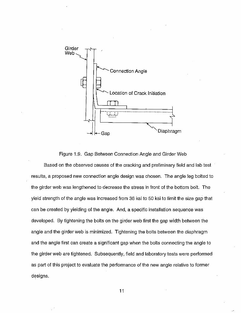
Figure 1.9. Gap Between Connection Angle and Girder Web
Based on the observed causes of the cracking and preliminary field and lab test
results, a proposed new connection angle design was chosen. The angle leg bolted to
the girder web was lengthened to decrease the stress in front of the bottom bolt. The
yield strength of the angle was increased from 36 ksi to 50 ksi to limit the size gap that
can be created by yielding of the angle. And, a specific installation sequence was
developed. By tightening the bolts on the girder web first the gap width between the
angle and the girder web is minimized. Tightening the bolts between the diaphragm
and the angle first can create a significant gap when the bolts connecting the angle to
the girder web are tightened. Subsequently, field and laboratory tests were performed
as part of this project to evaluate the performance of the new angle relative to former
designs.
11
CONCLUSIONS
Field measurements of distortion-induced stresses were made at welded
diaphragm-girder connections typical of the original bridge construction. The
measured stresses were compared with laboratory test results of other researchers.
These comparisons indicate the stress ranges at most connections are high enough
that fatigue cracking is expected at additional connections and reinitiation of fatigue
cracking is expected at some connections where hole drilling alone is used to repair
fatigue cracks in the girder webs.
Fatigue cracking of bolted connection angles used to replace original welded
connections was found to be strongly influenced by the gap between the leg of the
connection angle and the girder web. The gap results from fit-up error, the installation
procedure, and yielding of the angle due heavy trucks. A new angle design and
installation procedure was proposed and tested in the laboratory and in the field. The
new design performed better in the laboratory and field tests than the angle design
most commonly used by ALDOT in previous repairs. The test results indicate that the
likelihood of fatigue cracking of the new angle design is reduced but not eliminated.
The new installation procedure was used to install four lines of diaphragms in an
existing bridge, and the procedure appears practical.
Field installation and tests were performed using new diaphragms and
connection angles installed at two different distances below the top girder flanges (web
gap lengths). No significant difference resulted from the two different distances.
Hence, exiting holes in the girder webs for connection angle bolts drilled during
previous repairs can be used for installing angles of the new design.
12
Removal of all interior diaphragms to eliminate fatigue damaged diaphragm
girder connections from composite simple span bridges is feasible. Field tests and
Finite Element Method (FEM) analyses confirm that the increase in interior girder
stresses resulting from complete diaphragm removal is approximately ten to 15
percent. Removal of all interior diaphragms from continuous span non-composite
bridges is not feasible. For the bridges investigated, one line of diaphragms on each
side of the interior supports is required for bracing against lateral-torsional buckling.
The increase in stresses in typical interior girders is found to be approximately the
same as for simple span bridges and does not represent a significant increase.
Changes in the live load stresses in the exterior girders due to removing
diaphragms in both simple and continuous span bridges are insignificant. This
observation is important because the wind loading stresses on exterior girders are
significantly increased by removal of interior diaphragms. Wind loading is not critical
for the bridges investigated; however, the research results do show that a structural
evaluation including loading combinations with wind loading must be investigated
before removing all diaphragms from an existing bridge.
The increases in deck slab bending moments due to removing diaphragms are
slightly greater (5 to 7 percent) than the stress increases experienced by the girders.
From FEM analyses of a typical simple span bridge, the transverse positive bending
moments midway between the girders increased approximately 15 to 20 percent. The
negative transverse moments over the girders decreased. These results are
corroborated by theoretical results presented by Newmark (1946). Increased positive
13
moments may shorten the remaining life of the deck, but are judged not to have a
significant effect on the interstate highway bridges in Birmingham.
RECOMMENDATIONS
The following strategy for maintaining fatigue damaged diaphragm-girder
connections in multi-girder bridges with rolled section girders and channel diaphragms
is recommended based on the results of the research.
Removal of interior diaphragms (not at supports) is recommended to eliminate
unnecessary lines of interior diaphragms. Diaphragms at supports are necessary to
resist transverse horizontal loads and should not be removed for any reason. The first
line of diaphragms on each side of interior supports of continuous span girders are
necessary for bracing against lateral-torsional buckling and should remain in-place. A
structural evaluation should be performed on a candidate bridge to verify that
combined dead load, live load and wind load stresses on the exterior girders are
acceptable with the diaphragms removed. If these combined stresses are found
unacceptable, removal of only some lines of diaphragms and/or all interior diaphragms
except those between the exterior girder and first interior girder should be investigated.
Removal of only selected connections and diaphragms is desirable because
maintenance costs are avoided, or delayed, at some connections. Removal of
complete lines of diaphragms is not required. To repair fatigue cracking in parts of the
connection other than the girder web, an individual diaphragm can be removed to
eliminate the affected connection. To repair distortion-induced fatigue cracks in the
girder web, the diaphragms on both sides of the affected girder should be removed.
14
The fatigue cracks in the girder web should be repaired by drilling a hole at the crack
tips as in previous repairs.
Fatigue damaged connections at necessary lines of interior diaphragms should
be replaced with a bolted connection of the new design proposed here. The
connection angles should be installed by bolting to the girder web first then to the
diaphragm to avoid creation of a gap between the connection angle and girder web.
Connection angles should be installed with approximately a 90 mm gap between the
top of the connection angle and the bottom of the top girder flange. This will allow
existing holes from previous connection replacements to be utilized. Connections at
both ends of an individual diaphragm should be replaced at the same time to avoid
misalignment of the diaphragm. Fatigue cracks in the girder webs should be repaired
by drilling a hole at the crack tips (as performed in previous repairs) before installing
the new connections.
15
REFERENCES
American Association of State Highway and Transportation Officials (AASHTO). (1944). Standard Specifications for Highway Bridges. Washington, D.C.
Fisher, J.W., Jin, J., Wagner, D.C. and Yen, B.T. (1990). "Distortion Induced Cracking in Steel Bridge Members." Center for Advanced Technology for Large Structural Systems Report No. 90-07. Lehigh University. 101 pages.
Newmark, N. (1948). "Design of I-Beam Bridges." Proceedings. ASCE. Paper No. 2381.
Newmark, N. (1946). "Studies of Slab Beam Highway Bridges." University of Illinois Engineering Experiment Station. Bulletin Series No. 363.
16