2009 American WJTA Conference and Expo August 18-20, 2009 z Houston, Texas Paper FATIGUE PERFORMANCE ENHANCEMENT OF AWJ-MACHINED AIRCRAFT ALUMINUM WITH DRY-GRIT BLASTING H.-T. Liu OMAX Corporation, Kent, Washington, U.S.A. T. Gnäupel-Herold NIST Center for Neutron Research, Gaithersburg/University of Maryland, Department of Materials Science and Engineering, College Park, Maryland, U.S.A. Y. Hovanski, M. E. Dahl Pacific Northwest National Laboratory, Richland, Washington, U.S.A. ABSTRACT The effects of dry-grit blasting of AWJ-machined dog-bone specimens of aircraft aluminum with aluminum oxide abrasives were investigated in terms of enhancement in fatigue performance and mitigating concerns of abrasive contamination. Results obtained from fatigue tests have indicated that the surface roughness, R a , of AWJ-induced striations is inversely proportional to the fatigue life. The fatigue life of AWJ-machined and baseline specimens, excluding those processed subsequently with dry-grit and AWJ blasting, decreases with the increase in R a . Removal of the striations with dry-grit blasting only reduces the surface roughness somewhat and the resulted R a is still higher than that of the conventionally machined edges. The fatigue life of the dry-grit blasted specimens should not have exceeded that of the baseline counterparts. Yet the dry-grit blasting process has extended the fatigue life of the specimens by more than three times. Similar trend is observed for AWJ-machined specimens followed by AWJ blasting. The extraordinary boost in the fatigue performance could be attributed to the induction of residual compressive stresses by dry-grit and AWJ blasting and was subsequently confirmed experimentally. Dry-grit blasting could be carried out efficiently and cost effectively by stacking and the benefits gained from this secondary process simply outweigh the marginal cost increase. Therefore, waterjet technology combined with dry-grit blasting has the potential of not only lowering the costs for manufacturing aircraft aluminum but also significantly enhancing the fatigue performance. Organized and Sponsored by the WaterJet Technology Association
Transcript
2009 American WJTA Conference and Expo August 18-20, 2009 Houston, Texas
Paper
FATIGUE PERFORMANCE ENHANCEMENT OF AWJ-MACHINED
AIRCRAFT ALUMINUM WITH DRY-GRIT BLASTING
H.-T. Liu OMAX Corporation, Kent, Washington, U.S.A.
T. Gnäupel-Herold
NIST Center for Neutron Research, Gaithersburg/University of Maryland, Department of Materials Science and Engineering, College Park, Maryland, U.S.A.
Y. Hovanski, M. E. Dahl
Pacific Northwest National Laboratory, Richland, Washington, U.S.A.
ABSTRACT The effects of dry-grit blasting of AWJ-machined dog-bone specimens of aircraft aluminum with aluminum oxide abrasives were investigated in terms of enhancement in fatigue performance and mitigating concerns of abrasive contamination. Results obtained from fatigue tests have indicated that the surface roughness, Ra, of AWJ-induced striations is inversely proportional to the fatigue life. The fatigue life of AWJ-machined and baseline specimens, excluding those processed subsequently with dry-grit and AWJ blasting, decreases with the increase in Ra. Removal of the striations with dry-grit blasting only reduces the surface roughness somewhat and the resulted Ra is still higher than that of the conventionally machined edges. The fatigue life of the dry-grit blasted specimens should not have exceeded that of the baseline counterparts. Yet the dry-grit blasting process has extended the fatigue life of the specimens by more than three times. Similar trend is observed for AWJ-machined specimens followed by AWJ blasting. The extraordinary boost in the fatigue performance could be attributed to the induction of residual compressive stresses by dry-grit and AWJ blasting and was subsequently confirmed experimentally. Dry-grit blasting could be carried out efficiently and cost effectively by stacking and the benefits gained from this secondary process simply outweigh the marginal cost increase. Therefore, waterjet technology combined with dry-grit blasting has the potential of not only lowering the costs for manufacturing aircraft aluminum but also significantly enhancing the fatigue performance.
Organized and Sponsored by the WaterJet Technology Association
1. INTRODUCTION
For fatigue critical (“Class 1”) aerospace applications, aircraft aluminum parts are required to go through subsequent processing using more conventional machining/cutting method to remove the machining allowance (MA). In particular, abrasive-waterjet (AWJ) machining induces a unit pattern of striations (Chen et al., 2003) that could be a source for premature initiation of microcracking after many loading cycles. Unless specified otherwise, even for the fatigue non-critical parts (“Classes 2 through 4”), the default is “Class 1” for safety consideration. The requirement of a secondary process for AWJ-machined parts has greatly negated the merits (cost-effectiveness) of waterjet technology. Recognizing the tremendous cost advantage of AWJ machining and recent advancement in waterjet technology for precision machining, OMAX Corporation launched an R&D program to revisit and upgrade the specifications for AWJ machining. Some cost savings are envisioned if it can be shown that AWJ net cut parts have comparable durability properties as those conventionally machined and/or a cost effective secondary process could be identified.
A test matrix was designed to investigate the fatigue characteristics of AWJ-machined aluminum parts in combination with several subsequent machining processes. The fatigue characteristics of dog-bone specimens machined with a conventional CNC tool was used as the reference (baseline). To carry out the R&D program, two duplicate sets of AWJ-machined “dog bone” specimens were prepared for a range of edge qualities using two AWJ nozzles with different sizes of abrasives at up to five quality levels (Liu et al., 2009). Secondary processes including sanding, dry-grit and AWJ blasting were subsequently applied to several subsets of AWJ-machined specimens. CNC-machined specimens with the average surface roughness, Ra ≤ 1.6 μm, were used as the reference to assess the fatigue performance of AWJ-machined parts. Independent fatigue tests of AWJ-machined specimens, with and without secondary processes, were conducted in two laboratories. Test parameters were closely matched so that the test results could be reliably served to validate each other and to improve the statistical significance of the data.
The objectives were to determine the most cost-effective means in an attempt to take advantage of waterjet technology. The specific objectives are:
• How does the fatigue performance of AWJ-machined parts with minimum amplitude of striation fare with that of conventional-machined parts?
• Is there a low-cost secondary process that could be adopted to satisfy or surpass the requirements for fatigue critical performance, provided that the secondary machining process is still required?
The average surface roughness, Ra, measured at the bottom of machined specimens was used to characterize the specimens measured conventionally or with abrasive waterjets. Ra of the AWJ-machined surfaces at the highest quality level of 5 using 220-mesh garnet before and after sanding or grit blasting was around 3.1 and 2.4 μm. Test results show that the fatigue life is proportional to quality levels of AWJ-machined edges or inversely proportional to Ra of the striation pattern. Even at quality level five (Q5), the average fatigue life of AWJ-machined parts is about 30% shorter than those machined with conventional tools, consistent with the Ra measurements (Liu et al., 2009). From the surface roughness point of view, the fatigue life of the dry-grit blasted specimens should not have exceeded that of the baseline counterparts. Yet
the dry-grit blasting process has extended the fatigue life of the AWJ-machined specimens and the baseline counterparts by more than three times. Of interest is that all specimens except those going through grit and AWJ blasting broke at the gage area whereas the fatigue failure shifts from the gage area to the grip area for the grit- and AWJ-blasted specimens. Since the grit and AWJ blasted specimens did not break at the gage area, by definition, they have not physically failed at the termination of the fatigue tests. Therefore, the actual fatigue lives of the grit and AWJ blasted specimens are higher than the reported values corresponding to the test cycles at which the tests terminated. It is therefore important to recognize that the values thus reported are actually lower than the minimum fatigue lives of those specimens.
The extraordinary boost in the fatigue performance could be attributed to the induction of residual compressive stresses by dry-grit blasting. The ability to induce residual compressive stresses has been observed in related processes of “shot peening”, “waterjet peening”, and “abrasive-waterjet peening” (Meged, 2006; Wang et al., 1998a, 1998b; Dai and Shaw, 2007; Ramulu et al., 2000; 2002; and Arola et al., 2006). Liu et al. (2009) also conducted a finite element analysis to confirm that the fatigue failure would shift from the gage to grip areas provided the compressive stresses induced by grit and AWJ blasting are sufficiently large.
Since dry-grit blasting could be carried out via stacking, the combined process of AWJ machining and dry-grit blasting is still more cost-effective than conventional machine tools. If Liu et al.’s finding of three times plus enhancement in the fatigue life could be verified rigorously, the combined process would be a preferred choice for machining aircraft metals. This would certainly further broaden the market share of waterjet machine tools for high-value added jobs. A follow-on investigation was carried out with the objective of correlating the enhancement in fatigue performance and the induction of the residual compressive stresses by dry-grit and AWJ blasting. Residual compressive stresses of selected dog-bone specimens were measured by means of X-ray diffraction at the NIST Center for Neutron Research National Institute of Standards and Technology. In addition, Ra is used as the independent variable against which the fatigue life and residual compressive stress were plotted. It is important to quantify the effect of surface roughness on fatigue lives of specimens machined with different tools. We could then assess whether improvement in fatigue performance could be achieved by applying various secondary processes such as sanding, dry-grit and AWJ blasting.
Measurements of fatigue life and residual compressive stresses were conducted on selected dog-bone specimens made from aircraft aluminum ANSI 2024 (T3). Dog-bone specimens were machined by AWJs and CNC milling (baseline). For AWJ machining, two nozzles with garnet abrasives of different grit sizes were used. Secondary processes of sanding, dry-grit blasting, and AWJ blasting were performed on some of the AWJ-machined dog-bone specimens. The secondary processes were performed to reduce the surface roughness of the AWJ-induced striation. The average roughness, Ra, of the machined edges was measured at the gage of the dog-bone specimens to characterize their surface condition (Mahr/Federal Pocket Surf Model 2X-192586). This instrument uses a sampling length (aka. cutoff) of .03 and a sweep distance of .15). For the AWJ-machined specimens, Ra was measured at the bottom of the machined edge at which the roughness of AWJ-induced striation is the maximum.
It has been demonstrated that the fatigue life of AWJ-machined dog-bone specimens is slightly lower than their baseline counterpart. However, the fatigue life of dry-grit blasted AWJ-machined specimens increases at least three times that of the ones without dry-grit blasted and of the baseline counterparts, respectively. The dramatic increase in the fatigue life due to dry-grit
blasting is believed to be due to the “shot peening” effect as residual compressive stresses were induced by such a process. The present experiments were conducted as a follow-on work of Liu et al. (2009) to verify that dry-grit blasting indeed induces residual compressive stresses at the gage area. Furthermore, we intend to establish a quantitative correlation between the fatigue life and the induced compressive stresses. Also included are the results of AWJ-blasted specimens of which significant fatigue performance is found. For comparison, the measured fatigue life and residual compressive stresses were plotted against the measured Ra of dog-bone specimens.
2. EXPERIMENTAL METHODS AND FACILITIES
2.1 Abrasive-Waterjets
All except the conventionally machined specimens were machined with an OMAX’s JetMachining® Center Model 2652, equipped with two nozzles. Nozzles 1 and 2 correspond to MAXJET®5 and MINIJET, respectively. The dimensions of orifices and mixing tubes for these nozzles and the flow characteristics operating at 345 MPa are listed in Table 1. In the table, the diameter ratio refers to that of the orifice and mixing tube. Abrasives were gravity fed into the nozzle. The abrasive mass flow rate was controlled by the ID of the abrasive feed valve installed in the hopper. For AWJ blasting following AWJ machining, Nozzle 2 was modified by intentionally chip the orifice severely to generate a large jet spread such that the entire edge of the specimens could be covered.
2.2 Dog-Bone Specimen
Two sets of dog-bone specimens made from ANSI 7075 – T6 and 2024 – T3 were prepared for conducting independent fatigue tests (Liu et al., 2009). A subset of the 2024-T3 specimens was selected for measurements of residual compressive stresses at their gage. Figure 1 illustrates the geometry of the dog-bone specimens. The thickness of the dog-bone specimen is 3.175mm (0.125”). Among the specimens, one of the sets, 2OMS125-1/-5, was machined with conventional tools to Ra ≤ 1.6 μm (0.063"). The measured fatigue lives of these specimens served as the baseline for evaluating the fatigue performance of those machined with AWJs.
Three sets of specimens were first AWJ machined followed by three secondary processes. One of the secondary processes was conducted by sanding the gage area to Ra < 3.2 μm (0.125”). The other secondary process was to blast with dry 180-mesh aluminum oxide until the striation pattern visually disappeared. The third secondary process involved AWJ blasting of the gage area. The final AWJ-blasting process adopted is described below. In order to generate an AWJ with a wide spread to cover the entire thickness of the dog-bone specimens, nozzle 3 was modified from Nozzle 2 by installing a badly chipped orifice and a large ID mixing tube (see Table 1). The operating pressure was also lowered to 69.0 MPa to reduce the material removal rate. Preliminary results show that a two-step AWJ blasting processes must be used to reduce Ra to values comparable to that of the conventionally machined counterpart. The first step used 80-mesh garnet to blast the gage areas to remove the striation pattern; the second step used 220-mesh garnet to smooth the edge. Refer to the Appendix for a description of the dry-grit and AWJ blasting processes. ® JetMachining and MAXJET are registered trademark of OMAX Corporation
2.3 Fatigue Test Setup
Fatigue tests were conducted in the Fatigue and Fracture laboratory at PNNL. For the test, the specimen was gripped at its two ends with a cyclic loading applied until it failed. The number of cycles at which the specimen fails is defined as the fatigue life of that specimen. The test system used in this study was a MTS 50 Kip servo hydraulic test frame MTS model 312.31 that was controlled with an Instron 8800 digital controller. The load cell was a MTS 25 metric ton model 661.23A.01. The wedge action grips were a MTS model 647 controlled with a MTS model 585.60 grip supply.
Fatigue testing was performed in accordance with ASTM standards E466-96 and E468-90. Specimens were prepared per section 5.2.2.2 of E466, providing a continuous radius between ends of a rectangular cross section. Fatigue test parameters appropriate for the aluminum fatigue specimens were chosen. These parameters were in specified guidelines in applicable ASTM standards and required a maximum axial stress limit of 207 MPa (30 ksi) at the reduced gage section. As such, each specimen was measured in thickness and width using a standard digital dial caliper to five significant figures. The minimum cross-sectional area of the reduced gage section was determined using these measurements, and an appropriate load was selected to reach to the 207 MPa (30 ksi) limit. An R-value of 0.06 was specified for all testing, providing a ratio of minimum to maximum stress that always kept the specimen loaded in tension.
All fatigue testing was performed at ambient room temperature using constant amplitude loading. Standard lab practices were used for testing all fatigue specimens. Alignment of each test specimen was set and checked using mechanical stops against the hydraulic grips. Grip pressure was set at 19.3 MPa (2.8 ksi). Limits were set on the digital controller to protect the sample during loading and to detect fractures in the sample. The constant amplitude sine wave was observed on an oscilloscope during testing as a secondary verification of the load values that were set and displayed on the digital controller. The load cell in the test frame was verified prior to testing and post testing against a calibrated load cell.
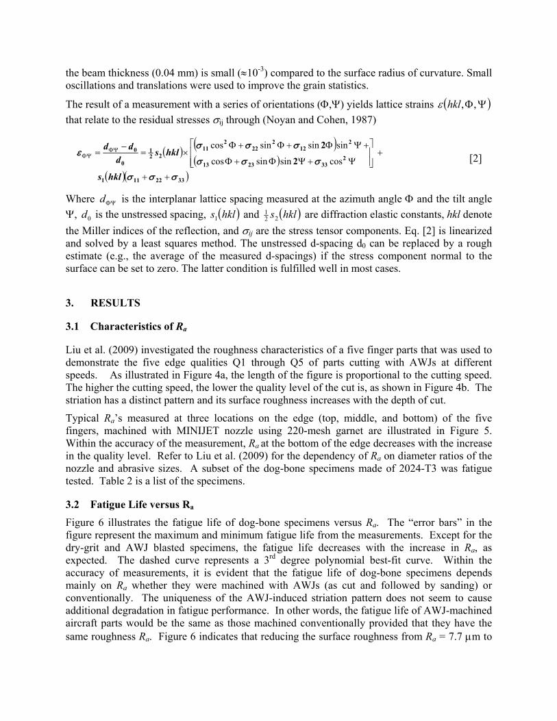
2.4 X-Ray Facility and Measurement Procedure Residual compressive stresses at the gage were measured using x-ray diffraction facility at NIST Center for Neutron Research. The basis for the evaluation of residual stresses by x-ray diffraction is the measurement of inter-atomic lattice spacings in crystalline materials using Bragg's equation:
θλ sin2 hkld= [1] Where λ is the x-ray wavelength, dhkl is the lattice spacing for the reflection defined by the Miller indices (hkl), and θ is the Bragg angle. As with any strain gage-based stress measurement, strains have to be measured in more than one direction, thus the need to rotate and tilt the specimen. The angles of rotation and tilt are commonly referred to as Φ and Ψ, respectively.
Sample mounting and tilt mode are shown in Figures 2 and 3, respectively. The wavelength was Cr-Kα, λ=2.2896 A, the reflection used was Al (311) at 2θ =140°. The range of psi-tilts (see Figure 3) was ±35° and lattice strains were measured for 21 different psi values in this interval. Curved surfaces such as for the specimens used here tend to produce geometric aberrations of the measured d-spacings. In order to avoid such detrimental effects, a small beam technique as described in Gnäupel-Herold (2009) was used with beam dimensions 3 mm × 0.04 mm such that
the beam thickness (0.04 mm) is small (≈10-3) compared to the surface radius of curvature. Small oscillations and translations were used to improve the grain statistics.
The result of a measurement with a series of orientations (Φ,Ψ) yields lattice strains ( )ΨΦ,,hklε that relate to the residual stresses σij through (Noyan and Cohen, 1987)
( ) ( )( )
( )( )3322111
2332313
212
222
211
221
0
0 2
2
σσσ
σσσ
σσσε
++
+⎥⎥⎦
⎤
⎢⎢⎣
⎡
Ψ+ΨΦ+Φ
+ΨΦ+Φ+Φ×=
−= ΦΨ
ΦΨ
hkls
hklsd
ddcossinsincos
sinsinsincos [2]
Where ΦΨd is the interplanar lattice spacing measured at the azimuth angle Φ and the tilt angle Ψ, 0d is the unstressed spacing, ( )hkls1 and ( )hkls22
1 are diffraction elastic constants, hkl denote the Miller indices of the reflection, and σij are the stress tensor components. Eq. [2] is linearized and solved by a least squares method. The unstressed d-spacing d0 can be replaced by a rough estimate (e.g., the average of the measured d-spacings) if the stress component normal to the surface can be set to zero. The latter condition is fulfilled well in most cases.
3. RESULTS
3.1 Characteristics of Ra
Liu et al. (2009) investigated the roughness characteristics of a five finger parts that was used to demonstrate the five edge qualities Q1 through Q5 of parts cutting with AWJs at different speeds. As illustrated in Figure 4a, the length of the figure is proportional to the cutting speed. The higher the cutting speed, the lower the quality level of the cut is, as shown in Figure 4b. The striation has a distinct pattern and its surface roughness increases with the depth of cut.
Typical Ra’s measured at three locations on the edge (top, middle, and bottom) of the five fingers, machined with MINIJET nozzle using 220-mesh garnet are illustrated in Figure 5. Within the accuracy of the measurement, Ra at the bottom of the edge decreases with the increase in the quality level. Refer to Liu et al. (2009) for the dependency of Ra on diameter ratios of the nozzle and abrasive sizes. A subset of the dog-bone specimens made of 2024-T3 was fatigue tested. Table 2 is a list of the specimens.
3.2 Fatigue Life versus Ra Figure 6 illustrates the fatigue life of dog-bone specimens versus Ra. The “error bars” in the figure represent the maximum and minimum fatigue life from the measurements. Except for the dry-grit and AWJ blasted specimens, the fatigue life decreases with the increase in Ra, as expected. The dashed curve represents a 3rd degree polynomial best-fit curve. Within the accuracy of measurements, it is evident that the fatigue life of dog-bone specimens depends mainly on Ra whether they were machined with AWJs (as cut and followed by sanding) or conventionally. The uniqueness of the AWJ-induced striation pattern does not seem to cause additional degradation in fatigue performance. In other words, the fatigue life of AWJ-machined aircraft parts would be the same as those machined conventionally provided that they have the same roughness Ra. Figure 6 indicates that reducing the surface roughness from Ra = 7.7 μm to
1.7 μm more than doubles the fatigue life. Smoothing the edges of specimens machined with the AWJ to Q3 with Nozzle 1 by sanding from Ra = 5.6 μm to 3.2 μm has improved only slightly the fatigue performance according to the trend of the best-fit curve.
The best-fit fatigue life for the combined AWJ and grit blasting process would have been 153 kilocycles according to the above criterion on the surface roughness. However, the actual fatigue life for the specimens prepared with the combined process is higher than 658 kilocycles, 4.3 times the best-fitted value, at which the fatigue tests were terminated because the specimens broke at the grip rather than at the gage. The actual fatigue life of specimens machined by the combined process is therefore not known but is at least 3.4 and 4.4 times longer that those machined by the conventional tool and by AWJs, respectively.
For the AWJ-blasted specimens, three out of the four specimens subject to fatigue tests broke at the grip area whereas one of them broke at the gage area. The one that broke at the gage area did not show any increase in the fatigue life. Apparently, the AWJ did not cover the entire gage area uniformly during blasting. As a result, there would be no residual compressive stress induced in the area that was missed by AWJ blasting and, therefore, no increase in fatigue performance. On the other hand, the specimens that broke at the grip area indicate the AWJ blasting had successfully covered the entire gage area uniformly and result in significant enhancement in the fatigue performance similar to those of grit-blasted ones. To compare the fatigue performance of AWJ-and dry-grit blasted specimens with those of the rest of the specimens, we treat the AWJ-blasted specimen that broke at the gage as an outlier and exclude the measured fatigue life of that specimen in calculating the average fatigue life.
Evidently, both the dry-grit and AWJ blasting processes have modified the surface and subsurface stress structure of the AWJ-machined edges leading to such a phenomenal enhancement in the fatigue performance. Literature has demonstrated that processes of “waterjet peening”, “abrasive-waterjet peening”, and “shot peening” are capable of inducing residual compressive stresses of the surface/subsurface of the workpieces (Meged, 2006; Wang et al., 1998a, 1998b; Dai and Shaw, 2007; Ramulu et al., 2000; 2002; and Arola et al., 2006). The residual compressive stresses are capable of retarding and inhibiting surface crack initiation and propagation under cyclic loading, leading to significant improvement in fatigue performance. Dry-grit and AWJ blasting processes are expected to be capable of inducing residual compressive stresses leading to the observed improvement in fatigue performance.
3.3 Fatigue Life versus Residual Compressive Stresses
Figure 7 illustrates the results of residual compressive stresses measured at the x-ray diffraction facility at NIST. The abscissa and ordinate are the surface roughness and residual compressive stresses, respectively. The error bars correspond to one standard deviation. The residual compressive stresses measured at two penetration depths of 20 and 60 nm using two wavelengths – Cr-Ka (0.29 nm) and Cu-Ka (0.154 nm). It is evident that the magnitude of the residual compressive stresses reduces with the penetration depth, as expected. The results show that the residual compressive stresses induced by conventional machining are the minimum for all specimens. The average residual compressive stresses induced by dry-grit and AWJ blasting processes are nearly 4 times those induced by conventional machining. These results correlate well with the increase in the fatigue life of the specimens machined with the combined process of AWJ and grit blasting, as illustrated in Figure 6.
It is interesting to point out that AWJ machining does increase the residual compressive stresses but appears to have little effect, if any, on enhancing the fatigue performance, as seen from Figure 6. Figure 7 shows that the maximum near-surface residual compressive stresses induced by dry-grit and AWJ blasting processes have magnitudes nearly equal to that of the 207-MPa load applied to the specimens during fatigue tests. With extrapolations from the stresses measured at the two depths of 20 nm and 60 nm, the induced surface stresses would even be closer or exceed the fatigue load. In other words, these specimens were only subject to a maximum tensile stress of about 20 MPa or less and were in compression during most of the fatigue cycles. On the other hand, specimens not dry-grit and AWJ blasted were subject to between 50 MPa to 150 MPa tensile stress and were in tension about half of the time or longer during the part of the fatigue cycle under tension loading. Based on the results shown in Figures 6 and 7, it is evident that Ra generally dominates residual compressive stresses. Induced compressive stresses become effective in enhancing fatigue performance only when their magnitudes are comparable to (or larger than) that of the loading of fatigue tests, particularly for specimens with small Ra.
3.4 Images of Failed Edges
To help understand the failure process of dog-bone specimens prepared by various processes during fatigue tests, the failed edges were visualized via micrographs. Attempts were made to determine whether we could identify how and where the fatigue cracks were initiated. It is hoped that understanding the source of crack initiation would help optimize the various processes to maximize the fatigue performance.
Figure 8 illustrates micrographs of the two halves of several failed specimens viewed with a microscope at 6.4X (Leica, Model WILDM3B). The micrographs were captured with a Dina digital camera (Model DVN 2001). The micrographs were oriented so that the bottom edge of the specimens coincided with that of the jet exit surface. At exit, the AWJ induced a minute burr that can be either detected visually or by touch. On the other hand, the edge of the entry surface is slightly rounded with no burr. At the common end of the edges, the shiny area corresponds to the yielding interface developed during the course of the fatigue tests. One of the sides of the shiny area coincides with a part of the bottom, top, or both surfaces of the specimen. For the AWJ-cut specimens with edge quality below Q4 (Figure 8a and 8b), yielding consistently begins at the bottom where the amplitude of striations is the maximum. This also applies to the Q3 AWJ-cut specimens (AS125) that are subsequently sanded (Figure 8c). Close examination of the shiny areas reveals the presence of fine features that converge toward the location where failure was initiated.
Note that sanding the AWJ-cut edges from Ra = 5.5 μm to 3.2 μm only removes the high spots but not the valleys of striations. The striation pattern on the AWJ as-cut surface is masked by the randomness of the rough surface. The characteristics of the striation pattern become recognizable after the AWJ-cut edge was sanded. Fatigue cracks are expected to initiate at the edge of the exit surface where Ra is still the maximum after sanding.
For the baseline specimens (MS125) with very small surface roughness Ra ≤ 1.6 μm, there appears to have no preference where yielding begins. Figure 8d shows that yielding begins at the edges of both the top and bottom surfaces for the specimen MS125-3. Other images of conventionally machined specimens show that yielding either begins on the top or bottom
surface. For the AWJ-cut specimens with quality levels greater than Q3, Figure 4 shows that the striation patterns deviate from those of the low-quality levels. At Q5, the striation pattern is straight and barely visible. Based on the surface roughness criterion, these specimens should behave similarly to those of the AWJ-cut and sanded ones. Examination of the failed specimens of AQ5220 with Ra = 3.5 μm shows that yielding begins at either surface. By grit blasting the AWJ-cut specimens AQ5220, Ra only reduces from 3.5 μm to 2.5 μm. In the absence of induced residual compressive stresses, these specimens would be expected to behave similarly to those between AWJ as-cut (AQ5220) and conventionally machined (MS125) parts. The grit-blast induced residual compressive stresses, however, strengthen the fatigue resistance of the gage area. The weakest spot shifts from the gage area to elsewhere. The specimens break at the grip area because that is where the cyclical loading is applied. As such, their actual fatigue lives are certainly higher than the recorded cycles when the tests terminated. The same applies to the AWJ-blasted specimens that their actual fatigue lives are higher than those plotted in Figure 6.
4. SUMMARY AND DISCUSSION
Test results have shown that the surface roughness Ra is the major factor in determining the fatigue life of aircraft aluminum dog-bone specimens whether they are machined conventionally or by AWJs with and without subsequent sanding (Figure 6). Significant enhancement in the fatigue performance is, however, achieved by a simple dry-grit blasting secondary process with 180-mesh aluminum oxide. Although the actual fatigue life of the grit-blasted specimens was not known because the recorded fatigue life corresponds to the loading cycle at which the tests were terminated due to failure of the specimens at the grip rather than the gage (the narrowest cross-section). The fatigue life of grit-blasted specimens is therefore at least 3 and 4 times longer than those of conventionally machined and AWJ as-cut counterparts, respectively.
The remarkable fatigue performance of the dry-grit and AWJ-blasted specimens is due to residual compressive stresses induced by these processes. There is abundant literature on improvement of fatigue performance due to similar processes such as shot, waterjet, and abrasive-waterjet peening (Meged, 2006; Wang et al., 1998a, 1998b; Dai and Shaw, 2007; Ramulu et al., 2000; 2002; and Arola et al., 2006). Measurements of residual compressive stresses of the specimens at NIST have confirmed that dry-grit and AWJ blasting processes indeed impart considerable increase in compressive stresses than conventional machining does, as illustrated in Figure 7. However, AWJ machining also leads to increase in compressive stresses but without noticeable improvement in the fatigue life.
Test results indicate that the fatigue life depends primarily on Ra, as established in the trend of the fitted curve in Figure 6, whether the specimens are cut with conventional or AWJ machining. The same dependency applies when conventional machining is applied as the secondary process to remove the AWJ-induced striation. Figure 6 implies that further reduction in Ra of the dog-bone specimens would not lead to meaningful benefits as far as enhancement of fatigue performance is concerned. From the machining point of view, one could achieve Ra ≈ 0.8 μm by using a good cutting head with special care. Additional grinding could achieve Ra ≈ 0.4 μm, whereas honing, lapping, or buffing could further reduce Ra ≈ 0.2 μm. The added machining costs for each halving of Ra would become increasingly expensive, as expected. Even for Ra ≈ 0.2 μm, the estimated fatigue life extrapolated from the fitted formula is 292 kilocycles which is not even half of the minimum counterpart of the grit-blasted specimens.
The processes of grit- and AWJ-blasting induce residual compressive stresses that are comparable to the maximum loading of fatigue tests. As such, the specimens are only subject to very low to no tensile stress for a very short duration during each fatigue cycle. The low or no tensile stress together with short exposure is the key to the significant enhancement of fatigue performance. Dry-grit blasting is considerably simpler and more cost-effective to apply than AWJ blasting. Therefore, the combined process of AWJ machining and grit blasting would offer an optimum solution for fatigue-critical applications for cost-effectiveness and operational simplicity. The combined AWJ machining and grit blasting is expected to be at least as cost-effective as conventional machining. The benefits of gaining a minimum factor of a three fold increase in fatigue performance by dry grit blasting simply outweigh the marginal increase in the manufacturing cost, if any. Furthermore, there is room for optimization of the combined process to achieve the maximum fatigue performance.
As the use of titanium on aircraft has been steadily increasing to replace aluminum, the R&D team is currently investigating the fatigue performance of titanium dog-bone specimens. Titanium has been used extensively on military aircraft and spacecraft because it is capable of operating at considerably higher temperatures than aluminum. Preliminary fatigue test results have shown a similar trend in increasing fatigue performance by dry-grit blasting.
ACKNOWLEDGMENT
This work is supported by an OMAX IR&D fund for the investigation of fatigue characteristics of AWJ-machined aluminum parts. Fatigue tests reported herein were conducted at PNNL’s material laboratory under the support of a TAP Agreement 08-02. AWJ-machining of the specimens was conducted by Mr. David McNiel, college intern at OMAX. Measurements of residual compressive stresses were conducted in the x-ray diffraction facility at National Institute of Standards and Technology. The efforts of Mr. Darren Stang for providing inputs to the interpretation of fatigue test results are acknowledged herein.
DISCLAIMER
Certain commercial firms and trade names are identified in this paper in order to specify aspects of the experimental procedure adequately. Such identification is not intended to imply recommendation or endorsement by NIST, nor is it intended to imply that the materials or equipment identified are necessarily the best available for the purpose.
REFERENCES
Arola, D., Alade, A. E., and Weber, W. (2006) “Improving Fatigue Strength of Metals using abrasive waterjet peening,” Machining Science and Technology, Vol. 10, No. 2, pp.197-218.
Chen, F.L., Wang, J., Lemma, E., and Siores, E. (2003) “Striation Formation Mechanisms on the Jet Cutting Surface,” J. Mat. Proc. Tech., Vol. 141, pp. 213-218.
Dai, K. and Shaw, L. (2007) “Comparison between Shot Peening and Surface Nanocrystallization and Hardening Processes,” Materials Science & Engineering. A. Structural materials: properties, microstructure and processing. Vol. 463, no. 1, p. 46-53.
Gnäupel-Herold, T. (2009) “Formalism for the Determination of Intermediate Stress Gradients using X-ray Diffraction,” J. Appl. Cryst. 42, 192–197
Hovanski, Y. and Dahl, M. E. (2008) “Fatigue Testing of Abrasive Water Jet Cut Specimens,” PNNL Report #17578, Prepared under TAP Agreement 08-02 and Contract No. DE-AC05-76RL01830, May, pp. 21.
Meged, Y. (2006) “Shot-Peening Effects on Metal Erosion,” J. Testing and Evaluation, Vol. 34, No. 4, Paper ID JTE12749.
Noyan, I. C. and Cohen, J. B. (1987) Residual Stress Measurement by Diffraction and Interpretation, Springer, New York (1987)
Ramulu, M., Kunaporn, S., Arola D., Hashish, M., and Hopkins, J. (2000) “Waterjet Machining and Peening of Metals,” ASME J. Pressure Vessel Technology, 122 (1), pp. 90-95.
Ramulu, M., Kunaporn, S., Jenkins, M. G., Hashish, M., and Hopkins, J. (2002) “Fatigue Performance of Waterjet Peened Aluminum Alloy,” ASME J. Pressure Vessel Technology, 123 (1), pp. 118-123.
Wang, S., Li, Y., Yao, M., and Wang, R. (1998a) “Fatigue Limits of Shot-Peened Metals,” J. Materials Proc. Tech., Vol. 73, pp. 57-63.
Wang, S., Li, Y., Yao, M., and Wang, R. (1998b) “Compressive Residue Stress Introduced by Shot Peening,” J. Materials Proc. Tech., Vol. 73, pp. 64-73.
Table 1. Dimensions and flow characteristics of two AWJ nozzles (p = 345 MPa)
¥ Orifice was intentionally chipped to increase jet spread for AWJ blasting
Table 2. Partial list of dog-bone specimens for fatigue tests
Specimen Number
# of Speci-mens Tested Conditions for Specimen Preparation
2OMS125-1/-5 4 Machined (Ra ≤ 1.6 μm) Baseline 2OAS125-1/-5 4 AWJ-cut Q3 & Sand to Ra ≤ 3.2 μm 80 mesh, Nozzle 1 2OAQ380-1/-5 4 AWJ-cut to Q3 80 mesh, Nozzle 1 2OAQ580-1/-5 4 AWJ-cut to Q5 80 mesh, Nozzle 1 2OAQ1220-1/-5 4 AWJ-cut to Q1 80 mesh, Nozzle 1 2OAQ3220-1/-5 4 AWJ-cut to Q3 220 mesh, Nozzle 22OAQ5220-1/-5 4 AWJ-cut to Q5 220 mesh, Nozzle 2
2OAQ5220T-1/-5 4 AWJ-cut to Q5 with sacrificial tape 220 mesh, Nozzle 22OAQ5220G-1/-5 4 AWJ-cut to Q5 & dry-grit blasted 220 mesh, Nozzle 22OAQ5220A-1/-5 4 AWJ-cut to Q5 & AWJ blasted 220 mesh, Nozzle 2
All SP00223 Kt 1.5 except for thickness; All in "L" direction Fmax of 209 MPa (30 ksi), R=0.06, 10 Hz; All gage section edges will be broken to 0.076 mm (0.003”) minimum.
Figure 2. Goniometer (with different samples) and sample mounting for fatigue specimens
Figure 1. Dog-bone specimen and typical AWJ machined part
a. AWJ-machined five-finger part at qualities 1
(Q1) through 5 (Q5)
b. Striation patterns for Q1 through Q5
Figure 3. Omega mode as used for measurements on the fatigue
Figure 4. Five-finger part machined with OMAX’s JetMachining Center
Figure 5. Ra of edges of five-finger parts machined with AWJ
APPENDIX - DESCRIPTION OF DRY-GRIT AND AWJ BLASTING PROCESSES
A-1. DRY-GRIT BLASTING PROCESS
The dry-grit blasting process is simple and cost effective to carry out. Ten specimens were stacked and held together with rubber bands. The air pressure was set at 414 KPa (60 psi). 180-mesh aluminum oxide was used as the abrasive. Each side of the stack was blasted twice: once for about 30 seconds and visually inspected for the obliteration of AWJ-induced striations, then blasted for
a. AQ1220-3 (broke at gage) e. AQ5220-1 (broke at gage)
b. AQ380-1 (broke at gage) f. AQ5220G-1 (broke at grip)
c. AS125-2 (broke at gage) g. AQ5220G-2 (broke at grip)
d. MS125-3 (broke at gage)
Figure 8. Micrographs of broken edges of the dog-bone specimens (6.4X)
another 15 seconds for a total of about 45 seconds per side. After dry-grit blasting, embedded garnet abrasives were mostly removed and garnet embedment became a non-issue. Note that the grit blasting process could be carried out by stacking many parts together during production runs to further increase productivity and lower costs.
A-2. AWJ BLASTING PROCESS
Several series of tests were conducted to determine the optimum procedures for reducing the Ra value of AWJ-machined edges. The following procedures were adopted:
• Intentionally chip an orifice with a 0.51 mm (0.02”) ID to generate a bad AWJ with a large spread to cover the entire thickness of the specimens
• A mixing tube with an ID of 1.07 mm (0.042”) was used with the chipped orifice. • A two-step process was used to blast the AWJ-machined edges. The first step used the nozzle
with the chipped 0.51 mm (0.02”) ID and 80 mesh garnet. The jet pressure, standoff distance, and abrasive flow rate were set to 69 MPa (10 ksi), 25.4 mm (1.0”), and 0.15 kg/min (0.335 lb/min), respectively. The edges of the specimens were blasted four times with the nozzle moving at a speed of 8.9 m/min (35 in/min).
• The second step uses the same nozzle but with finer garnet (220 mesh) to remove small roughness features left on the surface after blasting with the 80-mesh garnet. Under this condition, the edges of the specimens were blasted six times at the same nozzle speed.
• Figures A-a and A-b show the photos of edges before and after AWJ blasting. The first step of 80-mesh AWJ blasting is essential for reducing Ra effectively. Figure A-c illustrates photos of the specimen edges without the 80-mesh AWJ blasting. The 220 mesh garnet alone is too small to remove relatively large-scale surface roughness features.
a. Edges of AWJ-as-cut
specimens b. Edges after two-step (80- and
220-mesh) blasting c. Edges after single-step blasting (skip 80-mesh)
Figure A. Visual comparison of AWJ-as cut specimens before and after the AWJ blasting