International Journal of Electrical and Electronics
Engineering Research (IJEEER)
ISSN 2250-155X
Vol. 3, Issue 2, Jun 2013, 285-296
© TJPRC Pvt. Ltd.
FAULT ANALYSIS AND IMPROVEMENT OF POWER QUALITY USING 15 LEVEL
CASCADED STATCOM
J. H. V. VEERA RAGHAVA1 & K. CHANDRA SEKHAR
2
1Assistant Professor, R.V. R & J. C college of Engineering, Guntur, Andhra Pradesh, India
2Professor & Head of the Department, EEE, R.V. R & J. C college of Engineering, Guntur, Andhra Pradesh, India
ABSTRACT
Many static synchronous compensators (STATCOMs) utilize multilevel converters due to the following: 1) Lower
harmonic injection into the power system; 2) Decreased stress on the electronic components due to decreased voltages; and
3) Lower switching losses. One disadvantage, however, is the increased likelihood of a switch failure due to the increased
number of switches in a multilevel converter. A single switch failure, however, does not necessarily force an (2n + 1)-level
STATCOM offline. Even with a reduced number of switches, a STATCOM can still provide a significant range of control
by removing the module of the faulted switch and continuing with (2n − 1) levels. This approach introduces an approach to
detect the existence of the faulted switch, identify which switch is faulty, and reconfigure the STATCOM. This approach is
illustrated on an eleven-level STATCOM and the effect on the dynamic performance and the total harmonic distortion
(THD) is analyzed.
KEYWORDS: Fault Detection, Multilevel Converter, Static Synchronous Compensator (STATCOM)
INTRODUCTION
An inverter is a device that converts dc input power to ac output power at desired output of voltage and frequency.
The inverter is used to control the fundamental voltage magnitude and the frequency of the ac output voltage. It is evident
that the multilevel concept will be a prominent choice for power electronic systems in future years. Multi-level inverters
are the modification of basic bridge inverters. They are normally connected in series to form heaps of level. The output
voltage and power increase with number of levels. Adding a voltage level involves adding a main switching device to each
phase. Unlike the diode clamp or flying capacitors inverter, the cascaded inverter does not require any voltage-clamping
diodes or voltage balancing capacitors. The cascaded H-bridge multilevel Inverter uses separate dc sources (SDCSs). The
multilevel inverter using cascaded-inverter with SDCSs synthesizes a desired voltage from several independent sources of
dc voltages, which may be obtained from either batteries, fuel cells, or solar cells. The switches used in the inverter will
choose by voltage and frequency ratings. Since the inverter comes under medium voltage and medium frequency condition
we use IGBT‟s as the switches in the inverters.
As higher level converters are used for high output rating power applications, a large number of power switching
devices will be used. Each of these devices is a potential failure point. Therefore, it is important to design a sophisticated
control to produce a fault-tolerant STATCOM. A faulty power cell in a cascaded H-Bridge STATCOM can potentially
cause switch modules to explode [10] leading to the fault conditions such as a short circuit or an overvoltage on the power
system resulting in an expensive down time [11]. Subsequently, it is crucial to identify the existence and location of the
fault for it to be removed. Several fault detection methods have been proposed over the last few years [10]–[18]. Resistor
sensing, current transformation and VCE sensing are some of the more common approaches. For example, a method based
on the output current behavior is used to identify IGBT short circuits [12]. The primary drawback with the proposed
286 J. H. V. Veera Raghava & K. Chandra Sekhar
approach is that the fault detection time depends on the time constant of the load. Therefore, for loads with a large RL time
constant, the faulty power cell can go undetected for numerous cycles, potentially leading to circuit damage. Another fault
detection approach proposed in [13] is based on a switching frequency analysis of the output phase voltage. This method
was applied to flying capacitor converters and has not been extended to cascaded converters.
In this paper, the method we propose requires only that the output dc link voltage of each phase be measured. This
measurement is typically accomplished anyway for control purposes. If a fault is detected, the module in which the fault
occurred is then isolated and removed from service. This approach is consistent with the modular design of cascaded
converters in which the cells are designed to be interchangeable and rapidly removed and replaced. Until the module is
replaced, the multilevel STATCOM continues to operate with slightly decreased, but still acceptable, performance. In
summary, this approach offers the following advantages:
No additional sensing requirements;
Additional hardware is limited to two by-pass switches per module;
Is consistent with the modular approach of cascaded multilevel inverter; and
The dynamic performance and THD of the STATCOM is not significantly impacted.
PROPOSED NOVEL CONVERTER
Cascaded H-Bridge Inverter
Working Principle
Figure 1 shows the single cell of multilevel-cascaded H- bridge configuration. The output of this cell will have
three levels namely +V, 0 and –V. The switch position and the output voltage and the state of the H-Bridge are given in
table I. Using one single H-Bridge, a three level inverter can be realized. These H-Bridge cells can be connected in
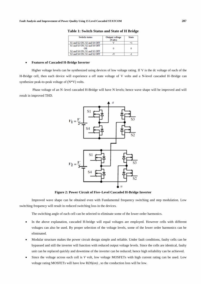
cascade to obtain multilevel-cascaded H-Bridge inverter. The power circuit of five level cascaded H-bridge inverter is
shown in figure 2. If V is the dc volt age of each H –bridge cell, then a five level inverter phase voltage will have five
levels namely +2V, +V, 0, -V and –2V. Similarly seven level inverter will have +3V, +2V, +V, 0, -V, -2V and -3V. A five-
level cascaded H-Bridge inverter requires two H-Bridges. A seven-level cascaded H-Bridge inverter requires three H-
Bridges. In general a N-level inverter requires (N-1)/2 H-Bridge cells in each phase and phase voltage will have N levels.
Figure 1: Power Circuit of Single H-Bridge Cell
Fault Analysis and Improvement of Power Quality Using 15 Level Cascaded STATCOM 287
Table 1: Switch Status and State of H Bridge
Features of Cascaded H-Bridge Inverter
Higher voltage levels can be synthesized using devices of low voltage rating. If V is the dc voltage of each of the
H-Bridge cell, then each device will experience a off state voltage of V volts and a N-level cascaded H–Bridge can
synthesize peak-to-peak voltage of (N*V) volts.
Phase voltage of an N–level cascaded H-Bridge will have N levels; hence wave shape will be improved and will
result in improved THD.
Figure 2: Power Circuit of Five–Level Cascaded H-Bridge Inverter
Improved wave shape can be obtained even with Fundamental frequency switching and step modulation. Low
switching frequency will result in reduced switching loss in the devices.
The switching angle of each cell can be selected to eliminate some of the lower order harmonics.
In the above explanation, cascaded H-bridge will equal voltages are employed. However cells with different
voltages can also be used. By proper selection of the voltage levels, some of the lower order harmonics can be
eliminated.
Modular structure makes the power circuit design simple and reliable. Under fault conditions, faulty cells can be
bypassed and still the inverter will function with reduced output voltage levels. Since the cells are identical, faulty
unit can be replaced quickly and downtime of the inverter can be reduced; hence high reliability can be achieved.
Since the voltage across each cell is V volt, low voltage MOSFETs with high current rating can be used. Low
voltage rating MOSFETs will have low RDS(on) , so the conduction loss will be low.
288 J. H. V. Veera Raghava & K. Chandra Sekhar
Figure 3: Fifteen Level Cascaded H-Bridge Inverter
The power circuit of the proposed fifteen level cascaded H-Bridge inverter is shown in Figure 3. The dc voltage of
each of the H-Bridge cells is set at 48Volts and the peak output voltage is 325 volts. The proposed fifteen-level inverter is
simulated in MATLAB-SIMULINK toolbox. A single-phase, 2KVA, R-L load of 0.866 power factor is assumed.
15-Level CMLI
Lastly, seven switching angles were calculated for 15-level CMLI for its 7 H-bridges using N-R method. The
calculated switching angles (including multiple solutions) are shown. In this case, more number of harmonic components
(six) as compared to 7 and 11 level CMLIs THD contents in output voltage reduces appreciably. The harmonic components
eliminated are 5th, 7th, 11th, 13th, 17th
and 19th. The output voltage THD content is calculated using equation (6) with
x=23 and the corresponding plot is shown. It is to be noted here that among different solution sets of switching angles
computed as above, the THD is computed by using those switching angles which are producing minimum THD (this
applies for the values of m where multiple solution exist).
It can be observed that THD level in output voltage is strictly satisfying IEEE-519 standard for normal working
range of modulation indices. Some of calculated switching angles have been shown in Table III for reference. By bringing
THD level below threshold value is very significant as THD produces various losses and undesirable effects in electric
power systems and equipments.
It can be observed that the range of modulation index for which solution for switching angles exist decreases with
the increase in number of levels but the occurrence of multiple solutions increase with the increase in number of level i.e.
for 7-level inverter only two sets of solution exist, for 11-level four sets of solution exist and for 15-level nine sets of
Fault Analysis and Improvement of Power Quality Using 15 Level Cascaded STATCOM 289
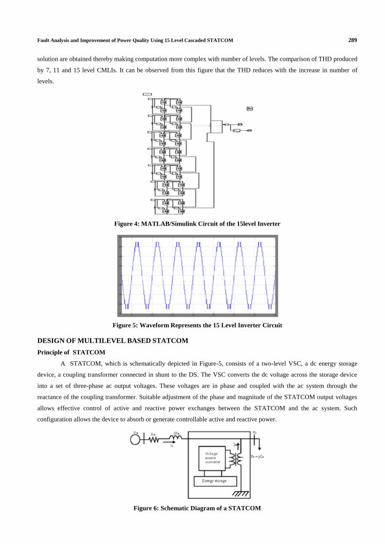
solution are obtained thereby making computation more complex with number of levels. The comparison of THD produced
by 7, 11 and 15 level CMLIs. It can be observed from this figure that the THD reduces with the increase in number of
levels.
Figure 4: MATLAB/Simulink Circuit of the 15level Inverter
Figure 5: Waveform Represents the 15 Level Inverter Circuit
DESIGN OF MULTILEVEL BASED STATCOM
Principle of STATCOM
A STATCOM, which is schematically depicted in Figure-5, consists of a two-level VSC, a dc energy storage
device, a coupling transformer connected in shunt to the DS. The VSC converts the dc voltage across the storage device
into a set of three-phase ac output voltages. These voltages are in phase and coupled with the ac system through the
reactance of the coupling transformer. Suitable adjustment of the phase and magnitude of the STATCOM output voltages
allows effective control of active and reactive power exchanges between the STATCOM and the ac system. Such
configuration allows the device to absorb or generate controllable active and reactive power.
Figure 6: Schematic Diagram of a STATCOM
290 J. H. V. Veera Raghava & K. Chandra Sekhar
Here, such device is employed to provide continuous voltage regulation using an indirectly controlled converter.
As shown in Figure-1 the shunt injected current Ish corrects the voltage sag by adjusting the voltage drop across the system
impedance Zth. The value of Ish can be controlled by adjusting the output voltage of the converter. The shunt injected
current Ish can be written as,
Ish = IL – IS = IL – (Vth – VL) / Zth (1)
Ish /_η = IL /_- θ (2)
The complex power injection of the STATCOM can be expressed as,
Ssh = VL Ish* (3)
Control for Reactive Power Compensation
The main aim of the control scheme is to maintain constant voltage magnitude at the load point. The control
system only measures the rms voltage at the load point, i.e., no reactive power measurements are required.
Figure 7: PI Control for Reactive Power Compensation
The controller input is an error signal obtained from the reference voltage and the rms terminal voltage measured.
Such error is processed by a PI controller; the output is the Id, which is provided to the PWM signal generator as shown in
figure-6. The PI controller processes the error signal and generates the required active power component to drive the error
to zero, i.e. the load rms voltage is brought back to the reference voltage.
Control for Harmonics Compensation
The Modified SRFT method is presented in [7]. It is called the instantaneous current component (id-iq) method.
This is similar to the SRFT method. The transformation angle „θ‟ is now obtained with the voltages of the ac network. The
major difference is that, due to voltage harmonics and imbalance, the speed of the reference frame is no longer constant. It
varies instantaneously depending of the waveform of the three phase voltage system. In this method the compensating
currents are obtained from the instantaneous active and reactive current components of the nonlinear load. In the same
way, the mains voltages V (a,b,c) and the available currents il (a,b,c) in α-β components must be calculated as given by (4),
where C is Clarke Transformation Matrix. However, the load current components are derived from a SRF based on the
Park transformation, where „θ‟ represents the instantaneous voltage vector angle (5).
𝐼𝑙𝛼𝐼𝑙𝛽
= 𝐶
𝐼𝑙𝑎𝐼𝑙𝑏𝐼𝑙𝑐
(4)
𝐼𝑙𝑑𝐼𝑙𝑞
= 𝑐𝑜𝑠𝜃 𝑠𝑖𝑛𝜃−𝑠𝑖𝑛𝜃 𝑐𝑜𝑠𝜃
𝐼𝑙𝛼𝐼𝑙𝛽
, 𝜃 = 𝑡𝑎𝑛−1 𝑉𝛽
𝑉𝛼 (5)
Figure 8: Block Diagram of SRF Method
Fault Analysis and Improvement of Power Quality Using 15 Level Cascaded STATCOM 291
Figure 8 shows the block diagram SRF method. Under balanced and sinusoidal voltage conditions angle θ is a
uniformly increasing function of time. This transformation angle is sensitive to voltage harmonics and unbalance; therefore
dθ/dt may not be constant over a period. With transformation given below the direct voltage component is
𝑖𝑙𝑑𝑖𝑙𝑞
= 1
𝑉𝛼2+𝑉𝛽
2 𝑉𝛼 𝑉𝛽
−𝑉𝛽 𝑉𝛼 (6)
𝑖𝑐𝛼𝑖𝑐𝛽
= 1
𝑉𝛼2+𝑉𝛽
2 𝑉𝛼 −𝑉𝛽𝑉𝛽 𝑉𝛼
𝑖𝑐𝑑𝑖𝑐𝑞
(7)
𝐼𝐶𝑜𝑚𝑝 ,𝑎
𝐼𝐶𝑜𝑚𝑝 ,𝑏
𝐼𝐶𝑜𝑚𝑝 ,𝑐
= 𝐶 𝑇 𝑖𝑐𝛼𝑖𝑐𝛽
(8)
Cascaded H-Bridge Multilevel Inverter
Figure 9: Circuit of the Single Cascaded H-Bridge Inverter
Figure 9 shows the circuit model of a single CHB inverter configuration. By using single H-Bridge we can get 3
voltage levels. The number of output voltage levels of CHB is given by 2n+1 and voltage step of each level is given by
Vdc/2n, where n is number of H-bridges connected in cascaded. The switching sequence is given in Table-I.
PWM Techniques for CHB Inverter
The most popular PWM techniques used for CHB inverter are 1. Phase Shifted Carrier PWM (PSCPWM), 2.
Level Shifted Carrier PWM (LSCPWM)
Case-1:- Phase Shifted Carrier PWM (PSCPWM)
Figure 10: Phase Shifted Carrier PWM
Figure-10 shows the PSCPWM. In general, a multilevel inverter with m voltage levels requires (m–1) triangular
carriers. In the PSCPWM, all the triangular carriers have the same frequency and the same peak-to-peak amplitude, but
there is a phase shift between any two adjacent carrier waves, given by φcr=3600/(m–1). The modulating signal is usually a
three-phase sinusoidal wave with adjustable amplitude and frequency. The gate signals are generated by comparing the
modulating wave with the carrier waves. It means for five-level inverter, four triangular carriers are needed with a 90°
292 J. H. V. Veera Raghava & K. Chandra Sekhar
phase displacement between any two adjacent carriers. In this case the phase displacement of Vcr1 = 0°, Vcr2 = 90°, Vcr1- =
180° and Vcr2- = 270°.
Case-2:- Level Shifted Carrier PWM (LSCPWM)
Figure 11: Level Shifted Carrier PWM (IPD)
Figure-11 shows the LSCPWM. The frequency modulation index is given by
mf = fcr / fm, (34)
where fm is modulating frequency and fcr are carrier waves frequency. The amplitude modulation index „ma‟ is
defined by
ma = Vm / Vcr (m-1) for 0 ≤ ma ≤ 1 (35)
Where Vm is the peak value of the modulating wave and Vcr is the peak value of the each carrier wave [1]. The
amplitude modulation index, ma is 1 and the frequency modulation index, mf is 6. The triggering circuit is designed based
on the three phase sinusoidal modulation waves Va, Vb, and Vc. The sources have been obtained with same amplitude and
frequency but displaced 120° out of the phase with each others. For carriers signals, the time values of each carrier waves
are set to [0 1/600 1/300] while the outputs values are set according to the disposition of carrier waves. After comparing,
the output signals of comparator are transmitted to the IGBTs. Figures 10, 11 and 12s how the waveforms based on three
schemes of LSCPWM: (a) in phase disposition (IPD) fig-11, where all carriers are in phase; (b) alternative phase opposite
disposition (APOD) fig-13, where all carriers are alternatively in opposite disposition; and (c) phase opposite disposition
(POD) fig-13, where all carriers above zero reference are in phase but in opposition with those below the zero reference
[1]. Out of IPD, APOD and POD; the authors studied that, IPD give better harmonic performance.
Figure 12: Alternative Phase opposite Disposition (APOD)
Figure 13: Phase opposite Disposition (POD)
Fault Analysis and Improvement of Power Quality Using 15 Level Cascaded STATCOM 293
MATLAB/SIMULINK MODELING AND SIMULATION RESULTS
Figure-14 shows the Matab/Simulink power circuit model of STATCOM. The system parameters chosen are
source voltage (Vs) as 11kv, 50Hz AC supply, DC bus capacitance 1550μF, Inverter series inductance 10mH, Source
resistance of 0.1Ω and inductance of 0.9mH. Nonlinear loads with resistance and inductance are chosen as 30mH and 60Ω
respectively.
Figure 14: Matlab/Simulink Power Circuit Model of STATCOM
Figure 15 shows the three phase source voltages, three phase source currents with STATCOM. It is clear that with
STATCOM even though load current is non sinusoidal, source currents are sinusoidal.
Figure 15: Source Voltage with STATCOM
Figure 16 shows the three phase source currents with STATCOM.
Figure 16: Source Current with STATCOM
Figure17 shows the load currents respectively with STATCOM.
Figure 17: Load Currents with STATCOM
294 J. H. V. Veera Raghava & K. Chandra Sekhar
Figure 18 shows the DC bus voltage is regulated to 11kv by using PI regulator.
Figure 18: DC Bus Voltage for PSCPWM
Figure 19 shows the phase-A source voltage and current, even though the load is non linear RL load the source
power factor is unity.
Figure 19: Phase-A Source Voltage and Current
Figure 20 shows the harmonic spectrum of Phase –A Source current without STATCOM. The THD of source
current without DSTACOM is 36.89%.
Figure 20: Harmonic Spectrum of Phase-A Source Current without STATCOM
Figure 21 shows the harmonic spectrum of Phase –A Source current with STATCOM. The THD of source current
with DSTACOM is 5.05%
Figure 21: Harmonic Spectrum of Phase-A Source Current with STATCOM
Fault Analysis and Improvement of Power Quality Using 15 Level Cascaded STATCOM 295
STATCOM with Fault in Gate Driver
Figure 22 shows the phase-A voltage of five level output of phase shifted carrier PWM inverter with fault in the
gate driver. The fault is applied between 0.1 and 0.2 sec.
Here one voltage level is missing during the period of fault.
Figure 22: Output Waveform with Fault
Figure 23 shows the filtered waveform by using the filter. The fall in the voltage is clearly observed during the
fault.
Figure 23: Filtered Waveform
Figure 24 shows the Active and reactive power waveforms with DSTACTOM
Figure 24: Waveform of the Active and Reactive Power with STATCOM
CONCLUSIONS
This paper presents Novel Hybrid H-Bridge multilevel converter. The proposed converter produces more voltage
levels with less number of switches compared to H- bridge configuration. This will reduce number of gate drivers and
296 J. H. V. Veera Raghava & K. Chandra Sekhar
protection circuits which in turn reduces the cost and complexity of the circuit. In this paper, the design procedure for
single cell based on cost and losses optimization is carried out. The selection of a single cell is based on SSOA (safe
operating Area) and Thermal Rating .The selection of capacitor and heat sink is also carried out. A SIMULINK based
model is developed and Simulation results are presented. The total harmonic distortion is also caluculated.THD before
fault is 0.64%, THD during fault is 1.28% and THD after the fault is 0.64%.
REFERENCES
1. J. S. Lai and F. Z. Peng, “Multilevel converters – A newbreed of power converters”, IEEE Trans. Ind. Appl.,
V32, No. 3, pp. 509-517, May/Jun.,1996.
2. José Rodríguez, Jih-Sheng Lai, FangZhengPeng “Multilevel Inverters: A Survey of Topologies, Controls, and
Applications “IEEE Trans. Ind. App, VOL. 49, NO. 4, August 2002.
3. K.A Corzine, and Y.L Familiant, “A New Cascaded Multi-level H-Bridge Drive,” IEEE Trans. Power.Electron.,
vol.17, no.1, pp.125-131. Jan 2002.
4. Manjrekar, M. D., Lipo, T. A. “A hybrid multilevel inverter topology for drive applications”. in Proc. of APEC,
1998, p. 523–529.
5. R. Schnell, U. Schlapbach, “Realistic benchmarking of IGBT – modules with the help of a fast and easy to use
simulation tool”.
6. Jean-Philipe Hasler, “DC Capacitor Sizing for SVC Light Industrial Application”.
7. G.Carrara, S.Gardella, M.Marchesoni, R.salutari,and G.sciutto, “A New Multilevel PWM Method; A theoretical
analysis,” IEEE Trans. Power.Electron., vol.7, no.3, pp.497-505. Jul.1992.
8. L.M.Tolber, T.G.Habetler, “Novel Multilevel inverter Carrier based PWM Method,” IEEE Ind.Appli., vol.35.
pp.1098-1107. Sep/Oct 1999.
9. Holmes, D. G. and Lipo, T. A., Pulse width modulation for power converters: principles and practice, IEEE.
10. V. Dinavahi, R. Iravani, and R. Bonert, “Design of a real-time digital simulator for a D-STATCOM system,”
IEEE Trans. Ind. Electron., vol. 51, no. 5, pp. 1001–1008, Oct. 2004.
11. B. Singh, S. Murthy, and S. Gupta, “STATCOM-based voltage regulator for self-excited induction generator
feeding nonlinear loads,” IEEE Trans. Ind. Electron., vol. 53, no. 5, pp. 1437–1452, Oct. 2006.
12. D. Soto and T. C. Green, “A comparison of high-power converter topologies for the implementation of FACTS
controllers,” IEEE Trans. Ind. Electron., vol. 49, no. 5, pp. 1072–1080, Oct. 2002.