International Journal of Science and Research (IJSR) ISSN (Online): 2319-7064 Index Copernicus Value (2013): 6.14 | Impact Factor (2013): 4.438 Volume 4 Issue 1, January 2015 www.ijsr.net Licensed Under Creative Commons Attribution CC BY Fault Detection in Transmission Line by Magnitude and Phase Angle Extraction based on Neuro – Fuzzy Approach G. Geetha 1 , Dr. K. Elango 2 1 PG Scholar, Valliammai Engineering College, Chennai, India 1 Professor & Head, Valliammai Engineering College, Chennai, India Abstract: The main aim of this paper is to detection and classifies the various types of ground and line faults in transmission line. A new current decomposition is proposed in order to derive the positive, negative and zero current components. The faults may be an insulation failure of conductors and cables, lightning or accidental faulty operation of any connected equipment. In a transmission line detection a fault is very important since if any fault occurs in finding fault may leads to disoperation of the transmission line protection system. So either a disturbances or steady state variations are called power quality variation. In this paper, a new concept is used for online symmetrical components and phase-angle extraction from high voltage transmission-line faults. This method is based on the fuzzy interference system and the instantaneous power theory. The average and oscillating terms of the powers in the αβ frame are separated by using fuzzy logic controller. After various shunt faults phase angle is estimated at each phase of the line. This approach is very much suitable for online implementation. Keywords: ANN, fuzzy interference system, instantaneous power theory, symmetrical components, unsymmetrical faults, transmission- line protection 1. Introduction In a power system, they are categorized in generation, transmission and distribution. Transmission system protection is mainly carried out by relay and circuit breaker. Relay is the sensing devices during any fault occur on the transmission line such as lightning and insulation failure of any conductors. The generated power should be transferred to load end without any loss through the transmission line [1], hence transmission system play a vital role in a power system. Over a last few decades, many papers are published for transmission line protection based on the wavelet transforms, artificial neural networks and other optimization techniques. All the real and reactive power calculation is based on the instantaneous power theory on the basis of stationary reference frames and Clarke’s transformation [2]. This method is very much suitable for the both steady state and transient state. It is also suitable during any non stationary conditions and unbalanced condition results in the distorted voltage. 2. Transmission Line Protection Fuzzy logic controller has the various engineering applications mainly on protection of power system. In recent years we used artificial neural network and also fuzzy for transmission lines protection, it has several studies such as fault detection, fault classification and fault location. The association of neural networks with fuzzy logic introduced to improve the architecture. The authors in [3] detect the fault based on the artificial neural network. An adaptive neural network and fuzzy interference system is used in [4]. This ANFIS is very effective including the low and high impedance faults accurately within the half a period of time cycle. Hence this ANFIS gives the more accurate results. 2.1 Direct and Inverse Current Computation In this paper, positive sequence current, negative sequence current and zero sequence current is terminology as a direct and inverse current. Based on the instantaneous power theory, symmetrical components are extracted. P-q power is calculated based on the above theory and also their average and oscillating components are separated. It is denoted as a p d, q d . Similarly inverse current is computed and it is denoted by p i , q i . In order for the transformation to be invertible, a third variable, known as the zero-sequence component, is added. The resulting transformation is (1) Where f represents voltage, current, flux linkages, or electric charge; and T is the transformation matrix. T αβ0 =2/3 (2) Paper ID: SUB15500 1187
Transcript
International Journal of Science and Research (IJSR) ISSN (Online): 2319-7064
Index Copernicus Value (2013): 6.14 | Impact Factor (2013): 4.438
Volume 4 Issue 1, January 2015 www.ijsr.net
Licensed Under Creative Commons Attribution CC BY
Fault Detection in Transmission Line by Magnitude and Phase Angle Extraction based on Neuro – Fuzzy
Approach
G. Geetha1, Dr. K. Elango2
1PG Scholar, Valliammai Engineering College, Chennai, India
1Professor & Head, Valliammai Engineering College, Chennai, India Abstract: The main aim of this paper is to detection and classifies the various types of ground and line faults in transmission line. A new current decomposition is proposed in order to derive the positive, negative and zero current components. The faults may be an insulation failure of conductors and cables, lightning or accidental faulty operation of any connected equipment. In a transmission line detection a fault is very important since if any fault occurs in finding fault may leads to disoperation of the transmission line protection system. So either a disturbances or steady state variations are called power quality variation. In this paper, a new concept is used for online symmetrical components and phase-angle extraction from high voltage transmission-line faults. This method is based on the fuzzy interference system and the instantaneous power theory. The average and oscillating terms of the powers in the αβ frame are separated by using fuzzy logic controller. After various shunt faults phase angle is estimated at each phase of the line. This approach is very much suitable for online implementation. Keywords: ANN, fuzzy interference system, instantaneous power theory, symmetrical components, unsymmetrical faults, transmission-line protection 1. Introduction In a power system, they are categorized in generation, transmission and distribution. Transmission system protection is mainly carried out by relay and circuit breaker. Relay is the sensing devices during any fault occur on the transmission line such as lightning and insulation failure of any conductors. The generated power should be transferred to load end without any loss through the transmission line [1], hence transmission system play a vital role in a power system. Over a last few decades, many papers are published for transmission line protection based on the wavelet transforms, artificial neural networks and other optimization techniques. All the real and reactive power calculation is based on the instantaneous power theory on the basis of stationary reference frames and Clarke’s transformation [2]. This method is very much suitable for the both steady state and transient state. It is also suitable during any non stationary conditions and unbalanced condition results in the distorted voltage. 2. Transmission Line Protection Fuzzy logic controller has the various engineering applications mainly on protection of power system. In recent years we used artificial neural network and also fuzzy for transmission lines protection, it has several studies such as fault detection, fault classification and fault location. The association of neural networks with fuzzy logic introduced to improve the architecture. The authors in [3] detect the fault based on the artificial neural network. An adaptive neural network and fuzzy interference system is used in [4]. This ANFIS is very effective including the low and high
impedance faults accurately within the half a period of time cycle. Hence this ANFIS gives the more accurate results. 2.1 Direct and Inverse Current Computation In this paper, positive sequence current, negative sequence current and zero sequence current is terminology as a direct and inverse current. Based on the instantaneous power theory, symmetrical components are extracted. P-q power is calculated based on the above theory and also their average and oscillating components are separated. It is denoted as a pd, qd. Similarly inverse current is computed and it is denoted by pi, qi. In order for the transformation to be invertible, a third variable, known as the zero-sequence component, is added. The resulting transformation is
(1) Where f represents voltage, current, flux linkages, or electric charge; and T is the transformation matrix.
International Journal of Science and Research (IJSR) ISSN (Online): 2319-7064
Index Copernicus Value (2013): 6.14 | Impact Factor (2013): 4.438
Volume 4 Issue 1, January 2015 www.ijsr.net
Licensed Under Creative Commons Attribution CC BY
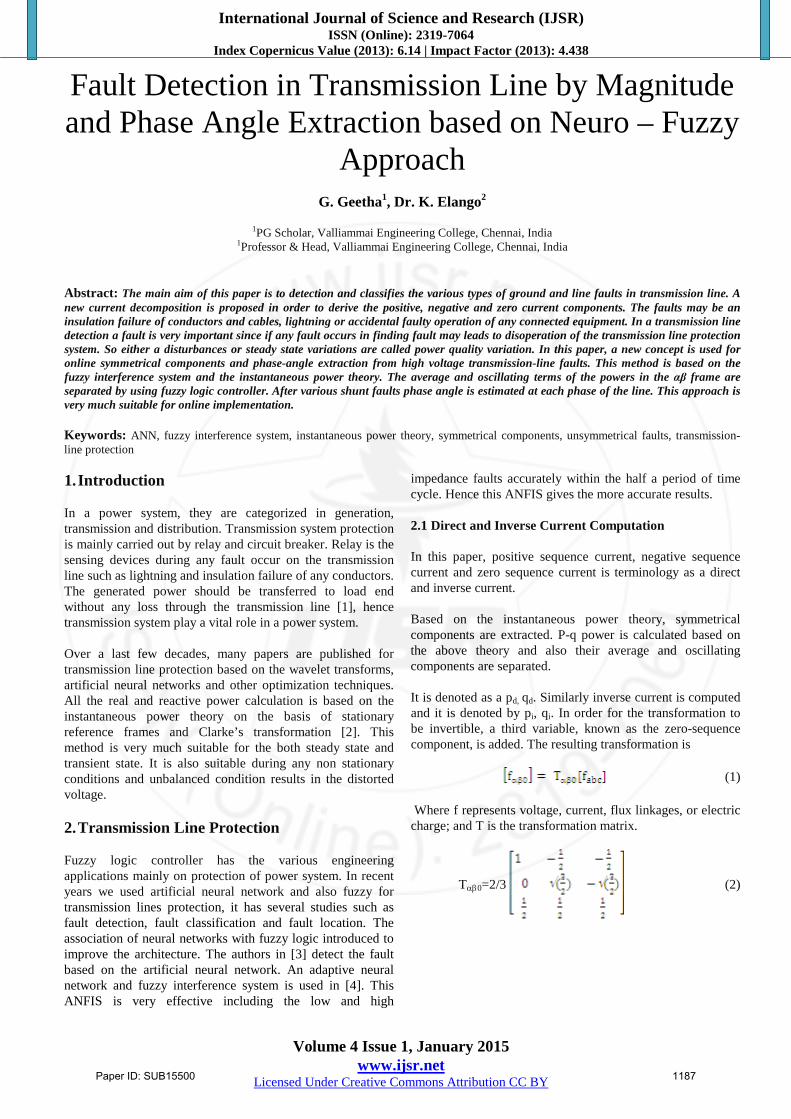
Figure1: Phasor diagarm for transformation
The Inverse Clarke transformation is expressed by the following equations:
Va=Vα (3)
Vb= (4)
Vb= (5) Thus PLL is an electronic module which locks the output to the input. Here voltage is taken as input for the P-Q computation after Clarke’s transformation and phase angle is taken as input for the fuzzy logic controller to separate average and oscillating components. The inverse transformation is given by
(6) Here we consider positive sequence current as a direct current, negative sequence current as a inverse current. This current is calculated based on following equation:
= √2/3 CT32 Iabc (7)
Then the real and reactive power is computed separately for direct components by following equations:
= (8)
= (9)
Pd= Vαd iβd + Vβd iβd (10)
Pi= Vαi iβi + Vβi iβi (11)
Where real power is taken as p = 3IcosΦ and reactive power is q = 3IsinΦ. The overall block diagram is given below; it uses instantaneous power theory for computing active and oscillating power after fault.
This equation can be decomposed into oscillatory and average terms:
Pl= Pl+Pl and Ql = Ql +Ql (12) Pl and Ql are oscillatory terms and Pl and Ql are average terms for easy analysis of real and reactive power computation and also for fault classification in transmission lines. 3. Fuzzy for Symmetrical Components The above procedure is used to classify the faults, in the three phase to ground fault in the beginning of the fault there will be presence of inverse and homopolar component current and it disappears at the end of the fault. During single line to ground fault following equation is obtained.
Ia1 = Ia2 = Ia0 = (Ia/3) (13)
If = 3Ia1 (14) To check the test system efficiency and also the robustness by varying the length of the transmission line as 50km, 100km and 200km, and also by changing the load angle. If any line to line fault occurs in the power system then the time taken fault occurring is more due to the presence harmonics components. This is because of mutual impedance between the phases. Hence the derived equations under the line to line fault condition:
Va1 = Va2; Ia0 = 0; Ia2 = -Ia1 (15)
If = Ib = - Ic = [3 Vf / (Z1 + Z2)] (16) Similarly for line to line ground fault occurs at any point in a test system. Let we consider fault occur between the two phases as b and c, then the following are the equations derived during fault in a transmission line as given below:
Va1 = Va2 = Va0 = (Va/3) (17)
Ia1 = Vf / [Z1+Z2Z0/(Z2+Z0)] (18)
If = 3Ia0 (19) The analysis of this different type of symmetrical components is used for the identification of nature of fault. During normal condition or any symmetrical fault conditions the zero sequence components and negative sequence currents are nearly equal to zero. The presence of only negative or inverse components represents the line to line fault has occurred in transmission line has been proposed in [14]. Similarly if negative or inverse component and zero or homopolar components presents in a transmission line be a double line to ground fault.
International Journal of Science and Research (IJSR) ISSN (Online): 2319-7064
Index Copernicus Value (2013): 6.14 | Impact Factor (2013): 4.438
Volume 4 Issue 1, January 2015 www.ijsr.net
Licensed Under Creative Commons Attribution CC BY
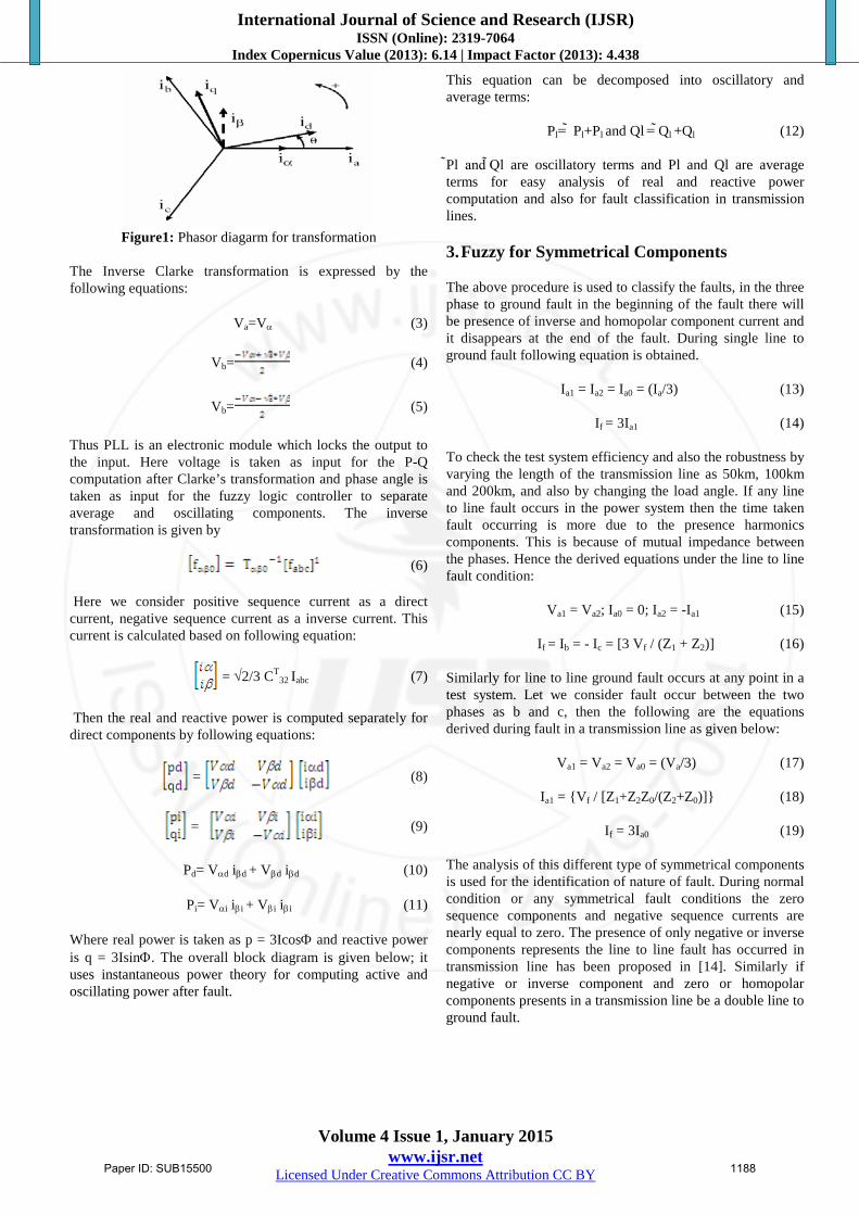
Figure 2: System under study for fault classification with the block diagram of the direct and inverse current
Fuzzy interference system is adjustable based on human operator decision or based on mathematical equations. In the MATLAB Simulink this simulation block diagram can be easily test the fuzzy logic controller. This given system can be done by using graphical tools or by using any command line functions or by using neuro fuzzy techniques. Let membership function is given by MF or x in A. The membership value always lies between 0 and 1. Generally in fuzzy interference system there are two types of expert system namely sugeno type and Mamdani type both are varied by its outputs. The process of mapping all the input to an output is carried out by fuzzy logic controller. Hence based on the mapping all the decision is done as classifying the various line and shunt faults.
Figure 3: Flowchart for fault classificaiton
The input to the fuzzy logic controller is instantaneous three phase current values, and also it takes the angle from PLL. Here trapezoidal membership functions used. This model is developed in MATLAB software using fuzzy logic tool box. From the input real and reactive power is calculated by using current and voltage from phase locked loop. The fuzzy rule is formed by applying fuzzy operator. The output of the membership function is shaped on the basis of firing strength of the rules. The product and minimum are most commonly used implication method. Raw data is extracted using Takagi-Sugeno system. It is developed by human expert systems that are purely linguistic rather than numerical data this steps are carried out as shown in Figure 3 Each rule of the output is added together by the process of aggregation. Implication process is performed by aggregation of truncated output. Defuzzifier is defined as the aggregated output of fuzzy set. In defuzzification process is the simplest and commonly used is gravity method. The information of all the inputs are combined to a single non fuzzy output which finds the type of fault occurred in transmission line. In this paper the membership functions are taken as a high, normal and low as fault range. It is denoted as follows: μ1, μ2, and μ3. The above functional block diagram Figure 2 as two sources connected through a transmission lines. Instantaneous current values are taken from three phase transmission line, and then current is measured by using current transformer. Three phase current values are converted to two phase reference frame as α and β by Clarke transformation. The Phase locked loop estimate voltage and phase angle by feedback loop. The reactive and real power is determined by using instantaneous power theory. Here fuzzy
International Journal of Science and Research (IJSR) ISSN (Online): 2319-7064
Index Copernicus Value (2013): 6.14 | Impact Factor (2013): 4.438
Volume 4 Issue 1, January 2015 www.ijsr.net
Licensed Under Creative Commons Attribution CC BY
block is used separately for direct current computation and inverse current. 4. Fault Classification By Fuzzy Nine different unsymmetrical faults types can be observed in this paper, three single line to ground faults, three double line to ground faults and three line to line faults. The symbol g represents the ground. The symbol a, b and c are represents the three phases as shown in the given Table 1 & 2.
Table 1: Fault Classification By Fuzzy - 100km
Type of Fault Normal | I | in kA Fault | I | in kA
Phase a-g 8.958 12.473
Phase b-g 8.8887 14.207
Phase c-g 8.9533 13.74
Phase a-b 9.4061 14.654
Phase b-c 8.956 15.063
Phase c-a 9.1357 14.087
Phase a-b-g 9.083 12.615
Phase b-c-g 9.2432 13.17
Phase c-a-g 9.369 12.093
Table 2: Fault Classification By Fuzzy - 50km
Type of fault Normal | I | in kA Fault | I | in kA
Phase a-g 9.2367 13.14
Phase b-g 9.1701 14.353
Phase c-g 9.233 14.021
Phase a-b 9.6864 16.358
Phase b-c 9.5217 15.22
Phase c-a 9.7125 15.901
Phase a-b-g 9.023 12.871
Phase b-c-g 9.6864 15.21
Phase c-a-g 9.7125 14.402
Table 1 and Table 2 shows the fault current magnitude estimated by the fuzzy interference system for all fault types in an unloaded system. Fault occurs at t=0.04 s to t=0.2 s and at the middle of the transmission line length (L=100km) with fault resistance of Rf=20Ω, by comparing the results in Table 4. However, for faults farthest from the first source, the fault magnitude estimation is less accurate. Thus, a complete fault detection and classification module is done using the fuzzy logic controller for classify all the different fault types in HV transmission lines, by considering different fault location as line length of 200km, 100km and 50km and also for different fault times.
Table 3: System Parameters Description Values
Source voltage(v) 200kv
Frequency(f) 50 Hz
Source resistance(Rs) 0.8929Ω
Source impedance(Ls) 16.58mH
Line length(L) 100km or 50km
Direct sequence impedance(Zd) 12.73+j293mΩ/km
homopolar sequence impedance (Zo)
386.4+j1295.7mΩ/km
5. Results and Discussion 5.1 Performance of the Fuzzy The following are results observed for the various types of ground faults and shunt faults the Figure 4 is the single line to ground fault waveform as given in the following sections.
Table 4: Fault Classification
Current Magnitude
Normal Condition MIN I(kA) MAX
I(kA)
During Fault MIN I(kA) MAX
I(kA)
Phase A 8.9581 10.0639 12.0936 14.6547
Phase B 8.8827 10.0233 12.0267 15.6329
Phase C 8.9481 10.3043 11.9689 14.8541
The Table 4 shows the minimum and maximum current ranges under normal conditions and also fault conditions. It explains for each phase separately. The identification of various shunt faults in transmission line is based on positive, negative and homopolar currents. Here from 1 to 60 harmonics range is considered, that is one full cycle. It consists for both even and odd harmonic ranges, the following are the various results obtained during line and shunt faults as shown. In figure 5 is the line to line fault, which shows the presence of both positive and negative sequence current components. After the various line faults and ground faults in transmission line have different phase angles as shown in Table 5. During line to ground fault, only the affected phase will have changes and in remaining two phases there will be no changes.
International Journal of Science and Research (IJSR) ISSN (Online): 2319-7064
Index Copernicus Value (2013): 6.14 | Impact Factor (2013): 4.438
Volume 4 Issue 1, January 2015 www.ijsr.net
Licensed Under Creative Commons Attribution CC BY
Figure 4: Single line to ground fault
At the time of line faults such as phase b to phase c fault, the current magnitude will be more higher than the gound faults. Since while any fault occurs on the transmission line the fault current will flow through the ground and also faulted line. The figure.6. shows the double to gound fault as phase c to phase a- ground fault.Here we can obserb the magnitude of current is less when compare with the line-line faults.
Figure 5: Line to line fault
The following parameters are used to identify fault in transmission line as shown in Table 3. Here the faults as said to be a power quality variation they are classified as either disturbances or steady sate variations. The following Table 4 shows variation of current during fault condition, it may be either line fault or ground faults. This interferes the normal flow of current is known as fault. In such a condition the fault current will tends to move in either through ground or through affected line.
Figure 6: Double line to ground fault
Table 5: Phase Angle Estimated By Fuzzy Type of fault Anga(o) Angb(o) Angc(o)
Phase a-g 5.26 126.3 117.5
Phase b-g 117.3 1.12 120.9
Phase c-g 126.8 119.3 1.12
Phase a-b 60.7 60.5 180
Phase b-c 180 59.1 59.9
Phase c-a 59.9 180 60.7
Phase a-b-g 50.2 62.3 171.2
Phase b-c-g 172.3 57.2 63.2
Phase c-a-g 63.2 180 55.27 6. Conclusion Thus the main objective of project is fault detection in the transmission line is done. The current magnitude for line to line faults such as phase a-phase b fault or phase b to phase c faults or phase c to phase a faults is high than the double line to ground faults as phase a to phase b to ground fault and so on. Similarly various phase angles are estimated at each fault. A new approach for online symmetrical components and phase-angle extraction from high-voltage transmission-line faults are detected and classified the various line faults and ground faults. The current transformation is proposed in order to derive the direct, inverse and homoploar sequence current as positive, negative, and zero sequence current components. Thus phase angle is determined after the various shunt faults occurs on transmission system. The average and oscillating terms of powers in the αβ frame are separated by using two fuzzy logic controllers. The fuzzy use a real power, reactive power, direct axis current angle and inverse axis current angle as inputs in order to learn the linear combination of the real and reactive power. The resulting symmetrical components are used by fuzzy for phase-angle estimation between direct and inverse current components. These phase angles permit classifying the fault types as single line to ground faults, line to line faults and double line to ground faults. Thus simulation results show the good performance and the accuracy in identifying the various transmission line faults. And also same procedure used to identify the three phase to ground fault or symmetrical fault to improve the protective schemes in transmission line. References [1] A. G. Phadke and J. S. Thorp, Computer Relaying for
Power Systems, 2nd ed. Hoboken, NJ: Wiley, 2009. [2] H. Akagi, E. H.Watanabe, and M. Aredes, Instantaneous
Power Theoryand Applications to Power Conditioning. Hoboken, NJ:Wiley/IEEE,2007.
[3] J. A. Jiang, C. s. Chen, and C. W. Liu, “A new protection scheme forfault detection, direction discrimination, classification, and location in transmission lines,” IEEE Trans. Power Del., vol. 18, no. 1, pp. 34–42, Jan. 2003.
[4] N. K. Nguyen, D. Flieller, P.Wira, and D. Abdeslam, “Neural network for phase and symmetrical components estimation in power systems,” in Proc. 35th Annu. Conf.
International Journal of Science and Research (IJSR) ISSN (Online): 2319-7064
Index Copernicus Value (2013): 6.14 | Impact Factor (2013): 4.438
Volume 4 Issue 1, January 2015 www.ijsr.net
Licensed Under Creative Commons Attribution CC BY
IEEE Ind. Electron. Soc., Porto, Portugal, Nov. 2009, pp. 3–5.
[5] Raj K. Aggarwal, Q.Y.Xuan,T. john, Furang Li and Allen Bennett, ”A novel approach to fault diagnosis in multicircuit transmission lines using fuzzy ARTmap neural networks,” IEEE Trans. Neural networks, vol. 10, no.5, Sep. 1999.
[6] Y. H. Song, Q. X. Xuan, and A. T. Johns, “Comparison studies of fiveneural network based fault classifiers for complex transmission lines,” Elect. Power Syst. Res., vol. 43, no. 2, pp. 125–132, Nov. 1997.
[7] P.K. Dash,A.K.Pradhan and G.Panda,”Applicaiton of minimal radial basis function neural network to distance protection,” IEEE Trans. Power Del., vol. 16, no. 1, pp. 68–74, Jan. 2001.
[8] Whei-Min Lin, Chin-Der Yang, Jia-Hang Lin and Ming-Tang Tsay,”A fault classification method by RBF neural network with OLS learning procedures,” IEEE Trans. Power Del., vol. 16, no. 4, pp. 473–477, Oct. 2001.
[9] T. Dalstein and B. Kulicke, “Neural network approach to fault classification for high speed protective relaying,” IEEE Trans. Power Del., vol. 10, no. 2, pp. 1002–1009, Apr. 1995.
[10] T. Bouthiba, “Fault detection and classification technique in EHV transmission lines based on artificial neural networks,” Eur. Trans. Elect. Power J., vol. 15, no. 5, pp. 443–454, 2005.
[11] M. S. Pasand, H. K. Zadeh, and O. P. Malik, “Transmission line fault detection and phase selection using ANN,” presented at the Int. Conf. Power Syst. Transients, New Orleans, LA, 2003.
[12] E. A. Mohamed, H. A. Talaat, and E. A. Khamis, “Fault diagnosissystem for tapped power transmission lines,” Elect. Power Syst. Res., vol. 80, no. 5, pp. 599–613, May 2010.
[13] F. L. Yousfi, D. O. Abdeslam, and N. K. Nguyen, “Adaline for fault detectionin electrical high voltage transmission line,” in Proc. IEEE 36th Annu. Conf. Ind. Electron. Soc., Glendale, AZ, 2010, pp. 1963–1968.
[14] O. Karacasu and M. H. Hocaoglu, “An Adaline based arcing faultdetection algorithm for single-pole autoreclosers,” Elect. Power Syst. Res., vol. 81, no. 2, pp. 367–376, Feb. 2011.
[15] Huisheng wang and W.W.L keerthipala,”Fuzzy neuro approach to fault classification for transmission line protection,” IEEE trans.power Del., vol.13, no.4, oct.1998.
[16] L.A. Zadeh, (1965), “Fuzzy Sets”, Journal of Information and Control, Vol 8, pp 338-353, USA.
[17] Biswarup Das and J.Vittal Reddy, ”Fuzzy-Logic-Based fault classification scheme for digital distance protection,” IEEE Trans. Power Del., vol. 20, no. 2, pp. 609–616, Jan. 2003.
[18] Math Works, MATLAB/Simulink R2008 (B) software, www.mathworks.com.
Author Profile
G. Geetha obtained her B.E. degree in Electrical and Electronics Engineering from Anna University, Chennai, and Tamilnadu, India in 2013. She is pursuing M.E-Power Systems
Engineering at Valliammai Engineering College under Anna University, Chennai in the Department of Electrical Electronics and Engineering. Her area of interest is power system analysis and power system protection based on neural networks, fuzzy logic controller, and other optimization techniques.
Dr. K. Elango received his B.E. degree in Electrical and Electronics Engineering from Alagappa Chettiar College of Engineering and technology at Madurai Kamaraj University,
Karaikudi, Tamilnadu, India in 1998. He received his M.E. degree in Power System Engineering from Annamaliai University, Chidambaram, and Tamilnadu, India in 2000. He received his Ph.D. degree in Congestion Management in Deregulated Power Systems from Anna University, Chennai, and Tamilnadu, India in 2012. He is reviewer of many international journals. He has published several technical papers in national and international journals and proceedings. His current research interests include the transmission congestion management in restructured power system, power system optimization. He is a member of the IEEE, ISTE and ISC.