Fault Tolerant
Electromechanical Actuators
for Aircraft
John William Bennett
A thesis submitted for the degree of Doctor of Philosophy
Newcastle University
School of Electrical, Electronic and Computer
Engineering
© November 2010
Preface 1
ACKNOWLEDGEMENTS
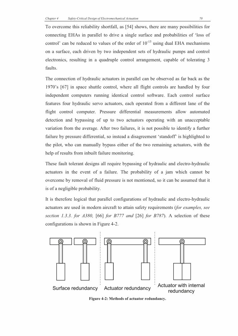
The author would like to thank BAE Systems, Eaton Aerospace Ltd. (formerly Fr-
HiTEMP), Goodrich Actuation Systems and Airbus UK for working alongside
Newcastle University on the two More Electric Aircraft projects and providing many
learning experiences along the way. Particular regards to Graham Mason for his awe-
inspiring knowledge of safety-critical control systems. Kind regards also to EPSRC
and the DTI for their financial contributions towards the research.
Thanks to those who’ve been my supervisors and mentors over the last decade,
Barrie, Dave and Alan. Thanks for providing a steady deluge of work, albeit often
enjoyable and also for frequently reminding me that doing the job is only part of the
task, understanding it is useful too.
Thanks to the many people who’ve passed through the doors of the Power
Electronics Drives & Machines laboratories; Glynn, Steve, Simon, Matthew, Little
Ross, Big Ross, Andrew, Chris, Ed and all the many others who’ve made working in
such a grim building into such a pleasant experience and have also imparted some
knowledge along the way.
Much gratitude to Darren, Jack, Allan, James, Chris, Stuart and the other technicians,
I’m the worst person in the world at delegating tasks, so thanks for sharing the
workload when actually given the chance. Without these gents, such a volume of
electric drives would not have passed out the door, or my cars passed so many
MOTs.
Kind regards to Steve and to the rest of my car club and also my many long-term
friends, for showing me that pulling cars apart and going out many times a week is
much more appealing than sitting down to write a long-overdue thesis. Again, thanks
for that....
And finally, thanks to my family and the biggest ‘thank-you’ to Linda, for
encouraging me to concentrate and complete this thesis and also for enduring months
and months of nights in, often seeing me only at the dinner table and putting up with
too many cases of ‘it’s nearly done’. When all is done and dusted, I’ve got some
making up to do...x
Preface 2
ABSTRACT
This thesis reviews the developments in commercial aviation resulting from More
Electric Aircraft initiatives. The present level of electromechanical actuation is
considered with discussion of the factors affecting more widespread use.
Two rather different electromechanical actuators are presented for commercial
aircraft; DEAWS electrical flap actuation and ELGEAR nose wheel steering. Both
projects are industrially driven with specifications based on existing medium-sized
commercial aircraft.
Methods comparing fault tolerant electric drive topologies for electrical actuators are
presented, showing two different categories of electric drive and comparing each
category in a variety of operating conditions to assess size and component count.
The safety-driven design process for electromechanical actuators is discussed with
reliability calculations presented for both proposed actuators, showing where fault
tolerant design is required to meet safety requirements. The selection of an optimum
fault tolerant electric drive for each actuator is discussed and fault tolerant control
schemes are presented.
The development of the electric flap and nose wheel steering systems is described,
with the focus on the work performed by the author, primarily on the power
electronic converters and control software.
A comprehensive range of laboratory and industrial results are given for both
actuators, showing demonstrations of fault tolerance at power converter and actuator
levels. Following testing, further analysis is given on various issues arising prior and
during testing of both converters, with design considerations for future
electromechanical actuators.
From design testing and analysis, the two projects can be compared to attempt to
determine the optimal electromechanical actuator topology and to consider the
challenges in evolving the two actuators to aerospace products.
Preface 3
CONTRIBUTIONS TO KNOWLEDGE
Contributions to knowledge in the field of power electronics, machines and drives
include:
· The first demonstration that new electromechanical actuators for flap actuation
and nose wheel steering can meet reliability and performance targets with the
introduction of fault tolerance.
· A new understanding of fault-tolerant permanent magnet drive configurations,
indicating how different options influence size and complexities for actuation-
type applications.
· New knowledge of how to produce fault tolerant actuation systems to meet
safety requirements, based on reliability data, aircraft interfaces and safety-
critical control schemes.
· Practical knowledge of optimal fault tolerant control strategies, gathered from
the implementation of the drive technologies in the new actuators, including two
torque ripple minimization techniques.
· Understanding of input filter sizing and torque synchronisation methods for fault
tolerant systems.
Preface 4
SYMBOLS & ABBREVIATIONS
A Amperes
A/D Analogue to Digital Converter
ac Alternating current
ACE Actuator Control Electronics
ASIC Application-Specific Integrated
Circuit
CMS Control and Monitoring System
CPU Central Processing Unit
DAC Digital to Analogue Converter
dc Direct current
DEAWS Distributed Electrically Actuated
Wing System
DSP Digital Signal Processor
DTI Dept. of Trade & Industry
EABSYS Electrically Actuated Braking
System
EHA Electro-Hydrostatic Actuator
EBHA Electrical Backup Hydraulic
Actuator
ELGEAR Electric Landing Gear Extend and
Retract
EMA Electromechanical Actuator
F.T. Fault Tolerant
FCC Flap Control Computer
FPGA Field-Programmable Gate Array
H.V. High Voltage
IGBT Insulated Gate Bipolar Transistor
LVDT Linear Variable Differential
Transformer
MCU Motor Control Unit
MTBF Mean Time Between Failure
NWS Nose Wheel Steering
PFC Primary Flight Computer
P.U. Per Unit
r/min Revolutions per minute
RVDT Rotary Variable Differential
Transformer
s Seconds
SPI Serial Peripheral Interface
THS Tail Horizontal Stabiliser
UART Universal Asynchronous Receiver
/Transmitter
V Volts
v.f. Variable Frequency
Preface 5
PUBLISHED WORK
From the work documented in this thesis, the author has co-written the following
papers which have been presented and published, or accepted for publication:
“Safety-Critical Design of Electromechanical Actuation Systems in Commercial
Aircraft”
Bennett, J.W. Mecrow, B.C. Atkinson, D.J. IET Electric Power Applications, 2010.
“A Prototype Electrical Actuator for Aircraft Flaps”
Bennett, J.W. Mecrow, B.C. Jack, A.G. Atkinson, D.J. IEEE Transactions on Industrial Applications,
May-June 2010, pp 915-921, Vol. 46, Iss. 3.
“A Fault Tolerant Electric Drive for an Aircraft Nose Wheel Steering
Actuator”
Bennett, J.W. Mecrow, B.C. Atkinson, D.J. Maxwell, C.J. Benarous, M. 5th
IET Power Electronics
Machines and Drives Conference, 2010.
“Failure Mechanisms and Design Considerations for Fault Tolerant Aerospace
Drives”
Bennett, J.W. Mecrow, B.C. Jack, A.G. Atkinson, G.J, IEEE International Conference on Electric
Machines and Drives, 6-8 September 2010.
“A Prototype Electrical Actuator for Aircraft Flaps and Slats”
Bennett, J.W. Mecrow, B.C. Jack, A.G. Atkinson, D.J. Sheldon, S. Cooper, B. Mason, G. Sewell, C.
Cudley, D. IEEE International Conference on Electric Machines and Drives, 15 May 2005, pp.41 - 47.
“Fault-Tolerant Control Architecture for an Electrical Actuator”
Bennett, J.W. Jack, A.G. Mecrow, B.C. Atkinson, D.J. Sewell, C. Mason, G. IEEE 35th Annual
Power Electronics Specialists Conference, 20-25 June 2004, pp.4371 – 4377, Vol.6.
“Choice of Drive Topologies for Electrical Actuation of Aircraft Flaps and
Slats”
Bennett, J.W. Mecrow, B.C. Jack, A.G. Atkinson, D.J. Sewell, C. Mason, G. Sheldon, S. Cooper,
B. Second International Conference on Power Electronics, Machines and Drives, 31 March - 2 April
2004, pp.332 – 337, Vol.1.
In addition the following papers have been presented on work involving the author
and described within this thesis:
“The Distributed Electrical Actuation of Aircraft Flaps and Slats”
Mason, G. Everndon, Bennett, J,. UK Magnetics Society, Electrical Drive Systems for the More
Electric Aircraft, one day Seminar, University of Bristol, 14 April 2005,
“Electrically Actuated Landing Gear for a Civil Aircraft Application”
Thomas, J. Maxwell, C. Benarous, M. UK Magnetics Society, More Electric Aircraft, one day
Seminar, University of Bristol, 2 April 2009,
Preface 6
TABLE OF CONTENTS
111 Electrical Actuation Systems in Commercial Aircraft ............................................... 9
1.1 Incentives for aircraft to become ‘More Electric’ ............................................ 10
1.2 Actuation in commercial aircraft ..................................................................... 12
1.3 More Electric Actuation in commercial aircraft .............................................. 14
1.3.1 The Electro-Hydrostatic Actuator ............................................................. 14
1.3.2 The Electrical Backup Hydraulic Actuator ............................................... 15
1.3.3 More Electric technologies in production aircraft ................................... 16
1.4 Reliability and safety........................................................................................ 19
1.5 Research into future technologies .................................................................... 21
1.5.1 Electrical generation and distribution ...................................................... 22
1.5.2 Electric fuel pumps .................................................................................... 25
1.5.3 Surface actuation ...................................................................................... 26
1.5.4 Actuator power converter research .......................................................... 28
1.6 Conclusions ...................................................................................................... 30
222 The DEAWS and ELGEAR Projects ........................................................................ 33
2.1 The Distributed Electrically Actuated Wing System ....................................... 33
2.1.1 Advantages of distributed electrical high lift surfaces .............................. 34
2.1.2 Reliability requirements for high lift surfaces .......................................... 37
2.1.3 Initial specifications .................................................................................. 38
2.2 The Electric Landing Gear Extend And Retract: Nose Wheel Steering .......... 39
2.2.1 Advantages of electrical landing gear actuation ...................................... 41
2.2.2 Reliability requirements for nose wheel steering ...................................... 42
2.2.3 Initial specifications .................................................................................. 43
2.3 Conclusions ...................................................................................................... 44
333 Fault Tolerant Drive Topologies ................................................................................ 46
3.1 Motor technologies........................................................................................... 47
3.2 Phase modules .................................................................................................. 48
3.3 Comparison under normal operating conditions .............................................. 49
3.3.1 A conventional 3-phase, ‘star’ connected motor ...................................... 50
3.3.2 Motors with n+1 isolated phases .............................................................. 52
3.3.3 Motors with multiple 3 phase sets (‘3n+3’) .............................................. 53
3.4 Comparison when operating at low speed ....................................................... 54
3.5 Torque ripple at standstill................................................................................. 57
Preface 7
3.6 Overall comparison .......................................................................................... 63
3.7 Conclusions ...................................................................................................... 65
444 Safety-Critical Design of Electromechanical Actuation .......................................... 68
4.1 Designing a electromechanical actuation system ............................................. 68
4.1.1 Existing fault tolerant actuator configurations ......................................... 68
4.1.2 Electromechanical actuator configurations .............................................. 71
4.1.3 Sensing the motor shaft angle in a fault tolerant drive ............................. 75
4.1.4 Position control of an electromechanical actuator ................................... 76
4.1.5 Communications and voting within a fault tolerant drive ........................ 78
4.1.6 Detection of signal and controller faults using voters .............................. 82
4.1.7 Implementation considerations for cross-communications ...................... 85
4.2 The DEAWS system ........................................................................................ 87
4.2.1 Selecting the topology ............................................................................... 87
4.2.2 The actuator control scheme ..................................................................... 95
4.3 The ELGEAR Nose Wheel Steering system .................................................... 99
4.3.1 Selecting the topology ............................................................................... 99
4.3.2 The actuator control scheme ................................................................... 102
4.4 Conclusions .................................................................................................... 106
555 Actuator Development and Construction ............................................................... 108
5.1 Design of the DEAWS actuator ..................................................................... 108
5.1.1 Motor ....................................................................................................... 109
5.1.2 Gearbox ................................................................................................... 113
5.1.3 Power electronic converter ..................................................................... 114
5.2 Design of the ELGEAR Nose Wheel Steering .............................................. 121
5.2.1 Design of the actuator and motor ........................................................... 121
5.2.2 Design of the motor drive electronics ..................................................... 126
5.3 Conclusions .................................................................................................... 132
666 Performance Analysis and Fault Handling ............................................................. 134
6.1 DEAWS testing and results ............................................................................ 134
6.1.1 Laboratory tests and results .................................................................... 134
6.1.2 DEAWS Industrial test setup ................................................................... 141
6.2 ELGEAR NWS testing and results ................................................................ 153
6.2.1 Newcastle University tests....................................................................... 154
6.2.2 Tests at Goodrich Actuation Systems ...................................................... 164
6.2.3 Tests at Airbus ......................................................................................... 167
Preface 8
6.3 Conclusions .................................................................................................... 169
777 Implementation Considerations for Electromechanical Actuators ...................... 172
7.1 Current shifting for torque ripple compensation ............................................ 172
7.2 Input power quality for multiple single phase drives ..................................... 177
7.3 ELGEAR lane synchronisation ...................................................................... 183
7.4 Implementing an actuator with a torque/speed profile ................................... 187
7.4.1 Implementation of a torque limiter ......................................................... 188
7.4.2 Operation under aiding load ................................................................... 190
7.5 Turn-off regeneration in low capacitance drives ........................................... 191
7.6 Conclusions .................................................................................................... 196
888 Conclusions ................................................................................................................ 199
999 Appendix A ................................................................................................................ 206
9.1 Minimum speed needed to overcome torque ripple ....................................... 206
9.2 Example of current reshaping ........................................................................ 207
9.3 Torque and current waveforms for n+1 phase motors. .................................. 208
111000 APPENDIX B ............................................................................................................ 210
10.1 DEAWS flap operation ................................................................................ 210
111111 Appendix C ................................................................................................................ 211
11.1 Further details on DEAWS hardware and software ..................................... 211
11.1.1 DEAWS control software ...................................................................... 211
11.1.2 DEAWS control hardware .................................................................... 213
11.1.3 DEAWS power electronic hardware ..................................................... 215
11.2 Further details on ELGEAR hardware and software ................................... 217
11.2.1 ELGEAR control software .................................................................... 217
11.2.2 ELGEAR control hardware ................................................................... 218
11.2.3 ELGEAR power electronic hardware ................................................... 220
111222 Appendix D ................................................................................................................ 222
12.1 Simulation of dual lane operation of ELGEAR NWS ................................. 222
111333 Index of Figures ......................................................................................................... 226
111444 References .................................................................................................................. 231
Chapter 1 Electrical Actuation Systems in Commercial Aircraft 9
111 EElleeccttrriiccaall AAccttuuaattiioonn
SSyysstteemmss iinn CCoommmmeerrcciiaall
AAiirrccrraafftt
ower in an aircraft can be defined as ‘primary’ or ‘secondary’ power.
Primary power is created by the propulsion system. Conventionally this involves
combusting aviation fuel in a gas turbine, producing thrust either with exhaust gases
– a ‘turbojet’/‘turbofan’, or by driving a propeller – a ‘turboprop’.
Secondary power is derived from the primary power by generators connected to the
engines. It is used to supply energy to all systems on the aircraft. On commercial
aircraft there are typically four forms of secondary power [1]:
· Hydraulic - for actuation of flight control surfaces.
· Pneumatic - for environmental control and wing de-icing.
· Electric - for avionics and utility functions.
· Mechanical - for engine driven ancillaries, such as fuel pumps.
By definition, an ‘electric aircraft’ would require both primary and secondary power
to be 100% electrical. Unmanned Aerial Vehicles, with battery energy storage and
electric motors driving propellers can be considered ‘electric aircraft’ [2] and studies
have considered the impact of scaling this technology to passenger aircraft [3].
Unfortunately there is still a requirement for considerable scientific and engineering
advancements, particularly in energy storage, before a purely electric passenger
commercial aircraft is viable. Attaining the thrust capability of a gas turbine engine
from a similarly-sized electric alternative is impossible with existing technology [3].
The concept of an aircraft with purely electrical power for the secondary systems was
considered as far back as the 1970’s. Despite retaining the use of gas turbines for
propulsion, this arrangement was named the ‘All Electric Aircraft’ (AEA). Various
P
Chapter 1 Electrical Actuation Systems in Commercial Aircraft 10
companies conducted studies into the feasibility of the AEA in the 1980’s, including
NASA with their Integrated Digital Electronic Aircraft program. Hoffman et al. [4]
predicted that an all-electric-aircraft could reduce aircraft weight by 10% and fuel
consumption by 9%. These improvements are based on predicted data for power
supplies, actuators and de-icing that are now considered inaccurate or unfeasible;
however, many principles of the study remain valid, in particular ‘load-sharing’.
Hoffman et al. suggest that conventional hydraulic, electrical and pneumatic systems
are under-utilised as the generators must be sized for the peak power conditions,
although for the majority of flight time the power requirements are much lower. Peak
loads do not occur simultaneously for the three systems, so a combined system could
be rated for considerably less than the combined peak powers, thus giving a
considerable size reduction. An electrical power supply was chosen for the combined
system since electricity is essential for avionics, lighting and the cabin, while
electrical actuators and electrical air conditioning can perform tasks normally
assigned to hydraulics and pneumatics respectively.
The studies of the 1980’s concluded that an AEA was feasible with existing
technology, but such a radical change in aircraft systems was a step-too-large for the
aerospace industry [1]. Instead, industry has aimed for a gradual adoption of
electrical technology into the secondary systems of their aircraft. This process of
change was named the More Electric Aircraft (MEA).
Subsequent MEA research programmes were initiated for military [5] and
commercial aviation, with the UK Department of Trade and Industry setting up a
MEA initiative in the 1990’s, supporting commercial aerospace manufacturers and
research institutions in various MEA-based projects (see section 1.5 for examples).
1.1 INCENTIVES FOR AIRCRAFT TO BECOME ‘MORE ELECTRIC’
There are many incentives for adopting more electrical systems on aircraft, but in the
case of commercial aircraft, the main underlying factor is financial. Many of the
potential advantages of electrical systems will inherently reduce operational costs –
for example any reduction in aircraft weight could be re-allocated to a saving in fuel,
an increased payload (passengers or cargo) or an increased range, all of these
increasing profitability [4,6]. Any reduction of fossil fuel burning can also be seen to
have environmental benefits.
Chapter 1 Electrical Actuation Systems in Commercial Aircraft 11
Although MEA do not feature the single secondary electrical power source of the
AEA, converting a proportion of hydraulic and pneumatic systems to electric can still
provide a reduction in net power supply weight by load-sharing. Weight reductions
are also possible by simplifying the distribution networks of secondary power
systems. Where networks of hydraulic pipes, pumps, valves, coolers and reservoirs
are replaced by electrical cables, there can be a net reduction in weight. In addition,
with future advances in technology, electrical power generators could be made
significantly smaller and more efficient by eliminating gearboxes and integrating
more closely with the engine.
Where electronics allows the removal of pipework, valves and mechanical linkages,
inspection and maintenance is reduced. Hydraulics require frequent inspection for
leaks and topping-up of fluid, whereas electronics require much less inspection time
and can offer self-diagnosis of degradation or failure. A reduction in the time
required for maintenance will result in lower servicing costs and more time for the
aircraft to remain in active service. Installation and removal of components can also
be simplified if the disconnection procedure of pipes or couplings is replaced by
unplugging of electrical connectors.
There is potential for electrical systems to offer improved reliability over existing
systems, which would increase the lifespan of components; however, it is an
essential requirement that the safety of an electrical actuator equals or betters that of
the system it replaces. By eliminating hydraulics from areas of potential combustion,
it has been suggested that electrical systems offer a safety advantage [7,8].
Electrical systems could also offer increased performance, versatility and efficiency.
Free from the restrictive pipework networks of hydraulics and with the potential for
improved functionality, electric actuators could be distributed to provide new levels
of flight control. Automated adjustment of flight control and engine systems already
provides a fuel saving in existing aircraft by improving aerodynamics and throttle
response [9] and this can improve with more widespread use of electric control
systems on the aircraft.
Hydraulics systems can be very noisy, with actuators often audible from the cabin, so
any reduction in noise with an electrical alternative would be considered a benefit to
passenger comfort.
Chapter 1 Electrical Actuation Systems in Commercial Aircraft 12
1.2 ACTUATION IN COMMERCIAL AIRCRAFT
An actuator is defined simply as an operating device and in the case of aircraft,
actuators are used to move components to allow manoeuvring on the ground and in
the air. Actuators are almost always hydraulic and much of the More Electric
Aircraft research involves investigating electrical alternatives.
Manoeuvring is performed with a variety of control surfaces or mechanisms on the
ground and throughout the flight, some of which are shown in Figure 1-1.
AileronsRudderElevatorsSpoilersFlapsSlats
Figure 1-1: Flight control surfaces.
The ‘primary’ control surfaces consist of:
· Ailerons. These are present on the outer trailing edge of the wings and control
the rotation of the aircraft along the longitudinal axis – i.e. the roll. The ailerons
on the two wings conventionally move in opposite directions.
· Rudder. The rudder is present on the tail and deflects left or right to alter the
rotation of the aircraft along its horizontal axis – i.e. the yaw.
· Elevators. These are situated on the horizontal tail fins and deflect up or down
to point the nose of the aircraft down or up, respectively – i.e. the pitch.
Chapter 1 Electrical Actuation Systems in Commercial Aircraft 13
The secondary controls and other actuation points include:
· Spoilers. Often referred to as air-brakes, these increase the drag on the wing,
allowing altitude to be reduced without pointing the nose downwards and
increasing airspeed.
· Flaps. These extend to increase the wing area, increasing the maximum lift co-
efficient and are used for take-off and landing. They are situated on the inside
trailing edge of each wing.
· Slats. These perform a similar task to the flaps by lowering the stall-speed of the
aircraft, thus aiding landing and take-off.
· Landing Gear. As well as take-off and landing, the landing gear is required for
taxiing to and from the runway. There are multiple actuators required for
stowing, deployment and steering.
In addition, ‘trim’ controls also exist to compensate for errors such as heading offsets
from aerodynamic and weight imbalances. For example, as cargo may not be ideally
centralized, the pilot can set the trim to counteract the effects, rather than manually
compensating via the primary controls for the duration of the flight. Some aircraft
simply use zero offset adjustments of the primary surfaces to set trim, while others
have additional actuated trim surfaces – for example the A380 features a horizontal
trim stabilizer on the tail (see 1.3.3).
The term ‘fly-by-wire’ was introduced in the 1960’s to commercial aircraft [9].
Whereas previously there were mechanical linkages between the control levers in the
cockpit and the actuator, fly-by-wire replaced this link with a sensor on the cockpit
lever and a wired analog/digital link to the actuator. Although control is electric, via
servo valves at the actuators, power is still provided by pressurised hydraulic supply
lines.
The term ‘power-by-wire’ applies to an actuator that is powered from an electrical
supply. An aim of the MEA initiative is to increase the quantity of power-by-wire
actuators on aircraft.
Chapter 1 Electrical Actuation Systems in Commercial Aircraft 14
1.3 MORE ELECTRIC ACTUATION IN COMMERCIAL AIRCRAFT
1.3.1 The Electro-Hydrostatic Actuator
One of the first developments of the More Electric Aircraft initiative was the Electro-
Hydrostatic Actuator (EHA), a hybrid electrical/hydraulic device and a successor to
similar actuators used in the Vulcan bomber of the 1950’s [10], but designed to meet
modern civil aviation safety standards. The actuator is hydraulic in operation;
however, the hydraulic fluid is self-contained and pressurised by an inbuilt electric
motor to move the actuator. Significant pressure is only required for movement,
resulting in an energy saving over the conventional hydraulic servo-actuator which
maintains pressure when holding [11]. As only an electrical supply is needed, the
EHA is power-by-wire, thus following the MEA path of migrating devices to
electrical generators and saving weight and maintenance by removing hydraulic
supply networks. There are also safety advantages in running electrical cables along
the fuselage rather than hydraulic pipes and less hazardous hydraulic fluids can be
used in localized systems than the conventional Skydrol™.
1 2
pumpmotorcontroller
x
x*
Figure 1-2: A380 EHA photo and topology (photo c/o Goodrich).
Internally, a power electronic converter drives a permanent-magnet, brushless dc
motor to speeds up to 10,000r/min and 50kW [7], to drive a pump, as in Figure 1-2.
By changing the direction the motor/pump, hydraulic fluid can be pumped into
chamber 1 to extend the actuator arm, or into 2 to retract. The device operates in
position control, with a linear position transducer (LVDT) feeding the arm angle
back to the controller. Without a hydraulic supply network in which to dissipate heat,
the casing of the actuator acts as a passive heatsink. When stationary the motor is
rotating at a low speed (100r/min) to overcome leakage flow in the actuator and
pump [12].
Chapter 1 Electrical Actuation Systems in Commercial Aircraft 15
EHAs could be considered an interim stage in the transition from hydraulic to
electromechanical actuation, although there are benefits in this hybrid approach:
· Hydraulic actuators can have a very high power density, which is increased as
fluid pressure is increased.
· With its compact design, an EHA can almost be considered a direct physical
replacement for a conventional hydraulic unit, so design of the aircraft can be
relatively conventional and thus more appealing to aircraft manufacturers.
· Upon failure, hydraulic rams will no longer be able to exert force and will
default to a damping action, rather than locking solid or exerting a drag force.
This allows the actuator to ‘fail-safe’, so where multiple actuators drive a
surface, the remaining actuators can still provide movement.
· As multiple EHAs can be used to drive a surface for safety backup purposes,
there is no requirement for backup technology within a single EHA, so a
conventional motor-converter can be used
1.3.2 The Electrical Backup Hydraulic Actuator
Figure 1-3: EBHA from A380 rudder (c/o Goodrich).
The Electrical Backup Hydraulic Actuator (EBHA) uses the modern electrical
technology of the EHA but in a rather different arrangement - the unit is a hydraulic
actuator with an electrical backup [9].
The actuator connects to the aircraft hydraulic supply for a primary source of power,
with electronics providing the control signals, as is normal with ‘fly by wire’. As a
back-up, the actuator also includes an electric pump which, in the event of hydraulic
supply failure, can pressurise the fluid in the actuator allowing full operation of the
hydraulics from an electrical supply.
Chapter 1 Electrical Actuation Systems in Commercial Aircraft 16
1.3.3 More Electric technologies in production aircraft
The Airbus A380 debuted in 2007, the largest commercial aircraft in the world and a
showcase for new technology, including many ‘more-electric’ approaches to flight
control actuation. Figure 1-4 shows the actuator configuration for the flight controls.
With the technologies available at the time of design, hydraulic and electro-hydraulic
actuation were considered a necessity due to the size of the aircraft and the forces
required. To minimise the size of the actuators, 5000psi was used, rather than the
conventional 3000psi. Hydraulic actuators are present on each type of control
surface, although where safety and design permits, electrical technology is used in
parallel or as a backup. In the event of a complete hydraulic supply failure, the
aircraft is capable of flight using 100% electrical and electro-hydraulic actuation,
although EBHAs are only intended for backup and are therefore rated for a short
operating cycle [13]. The total estimated weight saving due to the electro-hydraulic
actuators and moving to higher fluid pressure is claimed to be over 1.5 tonnes [10].
There are 8 spoiler surfaces on each wing, all of which use conventional hydraulic
actuators, bar surfaces 5 and 6 which use EBHAs. Two hydraulic power supplies
(‘green’ and ‘yellow’) are alternated between surfaces, so that if a supply fails, there
remains an even distribution of functioning spoilers across the wing.
As the spoilers employ hydraulic or electro-hydraulic actuators, failure of an actuator
will result in the actuator reverting to a damping mode, rather than a jam. The failed
surface will ‘blow back’ to an aerodynamically safe position, while the remaining
spoilers will be sufficient for air-braking. In the event of complete hydraulic failure,
the EBHAs on surfaces 5 and 6 will provide emergency functionality from electrical
supplies.
The three aileron surfaces of a wing are each powered by dual actuators, so loss of an
aileron would require failure of both actuators. The mid and inboard surfaces are
sufficient for flight control following an outboard failure, so both use an EHA in
parallel with a hydraulic actuator, allowing electrically powered operation in the
event of total hydraulic failure.
Elevators are similar to the mid and inboard ailerons in their use of hydraulic
actuators and EHAs on each surface. As elevators are flight critical, every surface
will be able to operate from an electrical source in the event of hydraulic failure.
Chapter 1 Electrical Actuation Systems in Commercial Aircraft 17
s.
Fig
ure 1
-4: A
rch
itecture o
f fligh
t con
trol su
rfaces in
the A
irbu
s A3
80
. Co
urtesy
of G
oo
drich
Actu
atio
n S
ystem
s.
E2
GY
S3
S1
P3
P1
P2
BB S
3S
2S
1S
2S
2S
1S
1S
3
GY
GY
GY
GY
12
34
56
78
GY
GY
GY
GY
12
34
56
78
SP
OIL
ER
SS
PO
ILE
RS
S2
S3
P2
S2
P1
YG
AIL
ER
ON
S
O/B
Med
I/B
YY
G AIL
ER
ON
S
O/B
Med
I/B
GG
Sp
eed b
rak
es, Gro
un
d sp
oilers
Roll su
rfaces
S3
P3
S1
S3
P3
P1
S1
S2
S2
E1
E1
P2
S3
E2
E2
P2
P3
P2
P3
Y
(Colo
rs on
E1
, E2
and
E3
for rep
resenta
tion
pu
rposes o
nly
, no en
gin
eering).
G
Con
ven
tion
al h
yd
raulic
servocon
trol.
EH
A, E
lectro
Hyd
rosta
tic Actu
ator.
EB
HA
, Elec
trical B
ackup
Hyd
rau
lic Actu
ato
r.
E1
E2
GR
EE
N h
yd
raulic
system
YY
EL
LO
W h
yd
raulic
system
E1
E1
AC
pow
er (AC
1ess sid
e 1)
E2
E2
AC
pow
er (AC
2ess sid
e 2)
E3
E3
AC
pow
er (AC
1 sid
e 1)
P1
, P2
, P3
,
S1
, S2
, S3
Prim
and S
ec F
ligh
t Con
trol C
om
puters
E1
E2
BB
BB
CM
ultim
ate b
ack
up c
on
trol
Rec
on
figu
ratio
n a
rrow
Elec
trical M
oto
r.
E1
E2
E1
E2
YG
TH
S
P3
P2
P1
P2
O/B
I/B
YG E
LE
VA
TO
RS
P2
P1
O/B
I/B
TH
SA
P1
EL
EV
AT
OR
S
trim
switc
hes
P3
B
GY G YP
1
P3
E1
E1
P2
E2
E3
BB
Vertic
al
Sta
biliz
er
Up
per
Ru
dd
er
Lo
wer
Ru
dd
er
S3
S1
P1
S1
S2
Sla
ts
GE
1
Fla
ps
GY
Ped
als
Feel a
nd
Trim
Un
it
28
VD
C1
ess2
8V
DC
1
S3
S1
Sp
eed b
rak
es, Gro
un
d sp
oilers
S2
S1
P2
P1
S2
S1
P2
P1
S1
S3
P1
P3
S1
S3
P1
P3
Com
mand
un
it: u
nit A
, unit B
Roll su
rfaces
E2
GY
S3
S1
P3
P1
P2
BB S
3S
2S
1S
2S
2S
1S
1S
3
GY
GY
GY
GY
12
34
56
78
GY
GY
GY
GY
12
34
56
78
SP
OIL
ER
SS
PO
ILE
RS
S2
S3
P2
S2
P1
YG
AIL
ER
ON
S
O/B
Med
I/B
YY
G AIL
ER
ON
S
O/B
Med
I/B
GG
Sp
eed b
rak
es, Gro
un
d sp
oilers
Roll su
rfaces
S3
P3
S1
S3
P3
P1
S1
S2
S2
E1
E1
P2
S3
E2
E2
P2
P3
P2
P3
Y
(Colo
rs on
E1
, E2
and
E3
for rep
resenta
tion
pu
rposes o
nly
, no en
gin
eering).
G
Con
ven
tion
al h
yd
raulic
servocon
trol.
EH
A, E
lectro
Hyd
rosta
tic Actu
ator.
EB
HA
, Elec
trical B
ackup
Hyd
rau
lic Actu
ato
r.
E1
E2
GR
EE
N h
yd
raulic
system
YY
EL
LO
W h
yd
raulic
system
E1
E1
AC
pow
er (AC
1ess sid
e 1)
E2
E2
AC
pow
er (AC
2ess sid
e 2)
E3
E3
AC
pow
er (AC
1 sid
e 1)
P1
, P2
, P3
,
S1
, S2
, S3
Prim
and S
ec F
ligh
t Con
trol C
om
puters
E1
E2
BB
BB
CM
ultim
ate b
ack
up c
on
trol
Rec
on
figu
ratio
n a
rrow
Elec
trical M
oto
r.
E1
E2
E1
E2
YG
TH
S
P3
P2
P1
P2
O/B
I/B
YG E
LE
VA
TO
RS
P2
P1
O/B
I/B
TH
SA
P1
EL
EV
AT
OR
S
trim
switc
hes
P3
B
GY G YP
1
P3
E1
E1
P2
E2
E3
BB
Vertic
al
Sta
biliz
er
Up
per
Ru
dd
er
Lo
wer
Ru
dd
er
S3
S1
P1
S1
S2
Sla
ts
GE
1
Fla
ps
GY
Ped
als
Feel a
nd
Trim
Un
it
28
VD
C1
ess2
8V
DC
1
S3
S1
Sp
eed b
rak
es, Gro
un
d sp
oilers
S2
S1
P2
P1
S2
S1
P2
P1
S1
S3
P1
P3
S1
S3
P1
P3
Com
mand
un
it: u
nit A
, unit B
Roll su
rfaces
Chapter 1 Electrical Actuation Systems in Commercial Aircraft 18
There are two rudders, each actuated with a pair of EBHAs. The configuration allows
a rudder to operate with a failure of an actuator, or multiple power supply failures.
The tail hydraulic stabilizer (THS), an additional secondary flight control on larger
aircraft, features a hydraulic actuator and an electric-hydraulic actuator. The electric-
hydraulic actuator contains both a hydraulic and electric motor with a speed-
summing gearbox, so either can move the actuator if the other is stationary or
jammed. All flaps and slats are powered via driveshafts from two speed-summed
motors within the body of the aircraft, both of which are hydraulic on the flaps, while
one motor is electric on the slats.
A summary of the key points in the A380 configuration can be made:
· Hydraulic actuators are the foremost source of actuation power.
· The entire architecture is arranged so that full functionality can be maintained
with the loss of an actuator, a power supply, a control signal and where
aerodynamically safe, complete loss of drive to a control surface.
· For surfaces which are critical to remaining airborne, functionality can be
maintained after failure of two power supplies.
· The aircraft can fly for limited periods using only electrically powered actuators,
although performance will be limited as a result of no functioning flaps and a
reduced number of active surfaces.
· The rudders are the only surfaces to feature solely electro-hydraulic actuators;
however, as EBHAs are used, they are still primarily driven from hydraulic
power supplies, with electrical providing the emergency backup.
· Only the slats and the tail horizontal stabiliser feature electromechanical
actuators. As a jam is considered a failure possibility in an electric motor, or the
associated mechanism (e.g. a ball screw), electrics are confined to control
surfaces which can either be locked in the event of a failure or as backup where
torque-summing gearboxes can overcome jams.
From a safety-backup viewpoint, the advantages of the More Electric approach are
made clear in the A380 architecture. With 2 hydraulic and 3 electric power sources
there are a total of 5 power supplies used on the flight control surfaces. This could all
be accommodated by 5 hydraulic supplies, but, as multiple electric power supplies
Chapter 1 Electrical Actuation Systems in Commercial Aircraft 19
would already be present for avionics and cabin electrics, re-using these as backup
supplies to actuators achieves the same 5 supply safety level with just 2 hydraulic
systems.
Another significant change from convention in the A380 is the introduction of
variable-frequency power generators. The variable frequency results from the
absence of Constant Speed Drives (CSD), mechanical devices translating a variable-
speed engine output to a constant speed mechanical input for an electrical generator
[14]. Removing the CSDs result in a weight saving and an estimated 50% increase in
electrical power system efficiency [10], although, since the generator output now
varies with engine speed, all connected electronics must operate from a power supply
frequency varying between 400 and 800Hz.
Although a very recent example, the A380 is not the first instance of More Electric
technologies in modern commercial aircraft. In the early 1990’s, Boeing were
implementing an electrical backup arrangement for the flaps and slats in the 777
[15]. The system is similar to the A380 in that central hydraulic motors drive the
flaps and slats, with electrical motors as backup. The main difference is that an
electric clutch couples the electric motor, rather than a speed summing gearbox. The
777 was also the first 100% fly-by-wire Boeing aircraft.
1.4 RELIABILITY AND SAFETY
The actuator arrangements described in section 1.3 are all derived from
comprehensive studies of component reliability and the reliability requirements for
safety regulations.
Reliability is conventionally expressed as a Mean Time Between Failure (MTBF),
with aerospace adopting the units of ‘flight hours’. A component with a MTBF of 1
billion flight hours would be predicted to suffer one failure if 1 billion of the
components were operated for 1 hour on an aircraft – i.e. a 1 in a billion chance of
failure during a 1 hour flight. MTBF is not an indication of lifespan, so a single
component would not be estimated to last 1 billion hours in service as degradation
occurs over time, decreasing the reliability.
When considering aircraft safety, the acceptable probability of a failure event
occurring determines the reliability requirements of the associated components. As is
convention with probability, failure probabilities are expressed as a fraction per flight
Chapter 1 Electrical Actuation Systems in Commercial Aircraft 20
hour, so a probability of 1.0 is a guaranteed failure during an hour of flight and
1×10⁻³
is a 1 in 1000 chance of failure during an hour of flight.
As an example; if the acceptable failure of the propulsion system is 1×10⁻⁹
, then the
combined MTBF of the propulsion-providing components must be 1 billion hours.
If no individual engine systems are available with this reliability, two engines can be
used and configured so both are completely independent and either capable of
propelling the aircraft. To calculate the implications of this, from ‘compound
probability’, the probability of two completely independent events occurring is equal
to the product of their probabilities:
1-1 baba PPP ´=&
If a and b are the failure probabilities of each engine and are considered to be of the
same value (as they are identical engines) then the probability of both occurring is:
1-2 2
aba PP =×
If for our example the allowed probability of both occurring is 1×10⁻⁹
, the minimum
reliability requirement for a single engine per flight hour is calculated as:
1-3 59 1016.3101 -- ´=´=aP
The MTBF requirement for a single engine is the reciprocal: 31,622 flight hours.
So, for a subsystem of failure probability p, putting n completely independent
subsystems in parallel gives a failure probability of pn.
Seemingly unfeasible reliability requirements can be met by putting backup sub-
systems in parallel. An electronic system with duplication of components to provide
alternatives when one fails is known has having redundancy. This allows continued
operation after a fault, referred to as fault tolerance.
There are restrictions to adding components in parallel, as the added complexity
results in more components that may fail. Using the engine example, if there are n
engines, each of reliability Pa, then the probability of a single engine failing, Ps, is:
1-4 as nPP =
If an engine was designed from eqn. 1-2 to precisely attain the failure probability of
3.16×10⁻⁵
and two engines were used in the aircraft, the probability of an engine
randomly failing is now 6.32×10⁻⁵
. While it may be allowable to fly with certain
component failures, increasing the component count to attain safety targets will
Chapter 1 Electrical Actuation Systems in Commercial Aircraft 21
ultimately result in more time with the aircraft out of service, undergoing repairs.
The use of more reliable components will result in fewer required in parallel to meet
safety requirements and thus reduce the maintenance requirements.
The safety requirements of actuation systems vary throughout the aircraft as they are
determined by the resulting severity of a failure. As can be observed in the A380, the
primary flight control surfaces must function throughout the flight, so multiple
actuators are present on multiple surfaces, with multiple power sources.
The safety requirements for loss of function are lower for flight surfaces that are not
critical to flight, but in which failure would result in reduced performance or an
emergency landing, although the faulted surface must not jeopardize the overall
control of the aircraft. For example, each spoiler surface on the A380 contains only
an individual actuator as air-braking can be performed from the remaining spoilers;
however, a failed spoiler must blow back under aerodynamic forces, so there must be
no jam of a failed actuator.
At the design stage, the failure probability of components is calculated using fault-
tree analysis, as shown for a rudder example on an unmanned aircraft in [16]. The
probability of a failure is derived from all potential failures leading to its occurrence,
resulting in a tree of associated events, with values based on sourced component
failure data.
1.5 RESEARCH INTO FUTURE TECHNOLOGIES
While the A380 is the commercial debut for many ‘power-by-wire’ technologies,
many existing aircraft are decades behind with some not fully fly-by-wire [9], let-
alone power-by-wire. With new replacements due for many aircraft, there are
opportunities to apply More Electric technologies, of similar levels to the A380 and
beyond.
The Totally Integrated More Electric System – TIMES was an initiative setup in
2001 [6] by a consortium of UK aerospace companies to investigate further
development of aircraft electrical technologies, including optimizing the design of
potential future aircraft around electrical technologies (rather than adapting
conventional aircraft or designing components to retro-fit). This section considers
some of the More Electric research from TIMES and other initiatives.
Chapter 1 Electrical Actuation Systems in Commercial Aircraft 22
1.5.1 Electrical generation and distribution
There is much scope for development in the electrical power generation on aircraft.
Although the direct-drive, purely electric system of the All Electric Aircraft could be
considered the goal, new developments aim to evolve the existing electric/hydraulic/
pneumatic systems in a More Electric Aircraft.
IntegratedDriveGenerator
acc.g’box
airstart
hyd.pump
High pressureshaft
electrical bus
hydraulic bus
step-asideg’box
CSD
electricalgenerator
Intermediatepressure shaft
Lowpressure shaft
Figure 1-5: Secondary power generation from triple-shaft turbofan engine.
Conventionally electrical power is derived through a series of steps (Figure 1-5):
· A step-aside gearbox derives a right angle output from the main engine shaft at
the high pressure spool section.
· The right-angle take-off shaft drives an accessory gearbox (for hydraulic and
pneumatics) and an Integrated Drive Generator.
· The IDG incorporates a CSD, capable of translating a variable speed mechanical
input into a constant speed mechanical output.
· The CSD mechanical output feeds an electrical generation unit which outputs a
constant 400Hz ac at 115V.
As discussed in 1.3.3, the A380 eliminates the CSD by effectively connecting an
electrical generator directly to the step-aside gearbox, resulting in a variable-
frequency ac supply. Conventional fixed-frequency generators are not suitable for
this arrangement so Oliaya et al. [17] describe the design of a new generator to
Chapter 1 Electrical Actuation Systems in Commercial Aircraft 23
accept the HP engine-speed shaft, at 11400 to 23400r/min and output an electrical
signal of 380 to 720Hz at 115V ac (120kVA). All electrical systems on the aircraft
must interface to the V.F. supply, so adaptation may be required in some cases where
400Hz-specific devices cannot accept 780Hz.
Research is ongoing into the next logical stage of optimizing the power generation;
to remove all gearboxes and drive a generator directly from the gas turbine. Provost
[18] proposes an idealised All Electric Aircraft arrangement with multiple electric
generators located within the gas turbine, directly on the 10~25kr/min intermediate
and high-pressure spool shafts and also on the low pressure spool at the rear of the
engine. Using the shaft-mounted generators, the design proposes an electrical link
between the intermediate and high pressure shafts of the engine, allowing improved
engine control and vastly simpler mechanics by reducing compressor stages and
eliminating bleed valves. Without pneumatics to start the engine, this feature will
instead be performed by the generator, acting as a starter motor. As there are no
accessory gearboxes, hydraulic and pneumatic supplies are derived electrically so an
electric alternative for wing de-icing will be required, as this is conventionally
achieved pneumatically using a hot air bleed from the engine. Although Provost
proposes a theoretical target, there is scope for incorporating aspects of the vision
into existing engines as part of the MEA initiative.
Powell et al. designed a prototype switched-reluctance machine for locating on the
high pressure spool shaft, intended to operate at 350 - 400°C [19] while Hall et al.
provided further research into this area, designing a switched-reluctance
starter/generator with an outer rotor to overcome mechanical expansion issues with
such a large, high speed machine [20]. With the More Electric aircraft requiring a
greater amount of electrical power generation, the machine is sized for 200kW
generation, with an input speed of 13,000r/min.
There are proposed generators to locate on the 1050-3100r/min low-pressure spool
shaft, with Mitcham and Cullen of Rolls-Royce discussing 250kW direct-drive and
geared permanent magnet generators using oil and air cooling to keep windings
below 250°C [21]. A direct drive 250kW prototype generator was subsequently
developed, with test data presented in [22]. A direct-drive, low pressure shaft
generator and power converter is also undergoing research [23] with a 70kW
Chapter 1 Electrical Actuation Systems in Commercial Aircraft 24
permanent magnet machine using 5 independent phases, each driven from a separate
power converter for fault tolerance.
In addition to normal generation, the low-pressure shaft can be used to provide 25kW
of emergency power from the windmilling effect of the engine, post failure. A 25kW
prototype permanent magnet generator was designed and constructed by Burrow et
al. [24], optimised for the windmilling condition, with the aim of eliminating the
emergency Run Air Turbine on the body of the aircraft. The generator operates over
a 3000-36000r/min range using a step-up gearbox from the LP shaft [25].
It is notable that all the generators proposed in [19-23] state or imply a dc output
from the power electronic converters, rather than the variable frequency ac of the
A380. With only theoretical aircraft considered for most research, a voltage standard
for future MEA & AEA power supplies is yet to be established; however, the high-
voltage dc supply is expected to become a reality, with the Boeing 787 featuring a
±270V dc power bus, derived by autotransformers/rectifiers on the ac bus [26].
The advantages of dc transmission, listed by Provost [18], include smaller
transmission cables (due to skin effect with ac transmission) and the elimination of
voltage converters within connected devices. Conventionally power electronic
converters use an internal interim dc stage, so a dc supply eliminates the requirement
for rectification. Bi-directional power flow is also simplified without an ac/dc
conversion stage.
There is a requirement for larger circuit breakers on dc supplies as there is no zero-
crossing point to break the circuit and there have been safety concerns over discharge
dangers, although research has shown dc systems actually achieve higher power
transmission capability than ac with the same cable density [27].
Both the high and low pressure shaft generators discussed by Hall and Mitcham
[20,21] suggest a need for fault-tolerance within the engine generators, with Todd
[23] demonstrating a separate electric controller for each phase of the generator for
fault-tolerance and Sun [22] presenting phase fault-mitigation strategies. With most
commercial aircraft featuring multiple engines, each driving separate electrical bus
generators, there is already an inherent redundancy of the power supplies. Although
no supporting data is given in [20, 21, 22 & 23] it could be inferred that the
reliability of an embedded electrical generator and drive cannot meet the reliability
Chapter 1 Electrical Actuation Systems in Commercial Aircraft 25
of an existing gearbox-based generator (see Figure 1-5) without fault-tolerance, or
that there is a desire to significantly increase the reliability of electrical generation.
Avery et al.[28] state that fault tolerance is applied in permanent magnet generators
to mitigate against the failure modes resulting in torque ripple or excessive winding
temperatures due to short circuits. The implications of generator failures on the
operation of a gas turbine must be considered if there is a risk of affecting the engine
operation and some of the possible fault conditions are investigated by Sun et al. [22]
on their 250kW fault tolerant generator.
It is also logical that, with an embedded electrical generator on a More Electric
aircraft proposing to supply an increased number of electrical devices, including
pumps to derive hydraulic supplies, safety requirements will be higher than those of
conventional generation.
1.5.2 Electric fuel pumps
Haylock et al. developed a 16kW prototype aircraft fuel pump in 1994-1997 [29].
The design was a ‘proof of concept’ that could evolve to replace conventional
mechanical pumps, offering improved control over flow rates, as opposed a flow rate
directly linked to the engine speed. The motor initially consisted of a 6-phase
brushless permanent magnet motor operating up to 13,000r/min and submerged in
aviation fuel. The pump pioneered a fault tolerant permanent magnet motor drive
arrangement, with each phase winding electrically, magnetically and thermally
isolated and individually controlled from an independent power converter. Full
output power capability is achievable with one motor winding or converter faulted.
The power electronic converters are capable of detecting short-circuits within motor
windings and taking remedial action to prevent over-heating. A 4-phase variant was
later produced [30], offering the same performance and fault tolerance, but with a
lower component count.
The 4-phase fuel pump motor was redesigned by Atkinson et al. [31] to a 100kW
prototype, capable of operating to 30,000r/min. The substantial redesign accounted
for the increased machine losses when scaling the permanent magnet 16kW motor,
reducing a potential 19kW of loss to 5.7kW. This prototype pump was sized for a
large future More Electric aircraft.
Chapter 1 Electrical Actuation Systems in Commercial Aircraft 26
The fault tolerant laboratory demonstrations described by Haylock focused on faults
within the motor and power-electronic converter. This work was taken a stage further
by Green et al., initially by evolving the power electric controller to operate
sensorless [32]. With work based on the original 6-phase motor, a sensorless scheme
for each motor phase was proposed, on the assumption that a true fault tolerant
electric drive would require an independent controller for each phase. This
eliminated the requirement for 6 mechanical position sensors. This ‘lanes of power’
approach was continued in [33], where a three-phase active rectifier was developed
for each motor phase controller, providing an interface to a variable-frequency
supply of 360 to 860Hz, 115Vrms, the proposed power supply for the A380 at the
time of research. The active rectifier approach was to allow bi-directional power
flow, minimise harmonic distortion and attain unity power factor.
1.5.3 Surface actuation
The present drive in actuation research is to move from the electro-hydraulic power-
by-wire solutions of the EHA and EBHA to purely electric EMAs (electromechanical
actuators). Whereas previously EMAs were considered too slow and bulky to
compete with hydraulics on surface actuation, the advent of digital motor drives and
improvements in motors have made the EMA more viable. Theoretically, alongside
an electro-hydraulic actuator, a modern EMA should be smaller as there is no
internal reservoir, stiffer as there is no fluid-based loading, more efficient without
fluid pumping losses and easier to maintain and store without hydraulic leaks [34].
The LEMAS – Large Electro-Mechanical Actuation System, is a prototype
laboratory actuator developed for application on the spoiler surfaces. Initial research
considered a selection of permanent magnet, brushless dc machines [35], although
finally a 4-phase switched reluctance motor was selected for the 25kW actuator [36].
The actuator has a linear arm arrangement, with the motor driving a gearbox to
operate a ball screw mechanism to move the spoiler.
Conventionally the spoiler surfaces use only one actuator per surface, as fault-
tolerance is achieved at the wing-level by multiple spoilers (see 1.3.3 for A380
example). Although re-emphasised in [36] that fault tolerance is not a requirement, a
topology is considered for the SRM with each of the 4 phases capable of running
from individual power electronic converters. Although the fault tolerance allows
electric drive and supply failures, there is no mechanism in LEMAS to overcome a
Chapter 1 Electrical Actuation Systems in Commercial Aircraft 27
mechanical jam in the system, preventing the spoiler from blowing back in the event
of a failure.
A very similar spoiler actuation system, also employing a switched-reluctance motor
is proposed by Fronista et al. [37] although the work presented is in the conceptual
stages with an identical motor-level fault tolerant scheme.
The ball screw and roller screw are the common choice for linear actuators, based
around a threaded screw shaft, a threaded nut and ball bearings or rollers in-between.
Although these devices are not found on primary control surfaces of commercial
aircraft, they often feature secondary surfaces such as flaps and slats. Throughout the
service life of Concorde, roller screws performed gate actuation of the engine air
intakes with no failures [38].
Garcia et al., discuss the EMA for primary flight control surfaces [39] drawing
comparisons with the EHA and highlighting the susceptibility of jamming as a major
issue with the adoption of the EMA in aircraft. The solutions proposed are to
eliminate gearboxes using a direct-drive motor and ball screw arrangement and to
improve fault-monitoring to pre-empt jam conditions in the motor or ball screw.
Work on a technology demonstrator of direct-drive EMA was described by Gerada et
al. in [40]. A rollerscrew is used, so although gearbox-free, the screw mechanism
infers a rotary-linear gearing ratio, allowing huge loads to be driven by relatively low
torques. Permanent magnet motors with high pole numbers were simulated with
results for fault mitigation of open circuit phases and terminal short circuits.
Although intended for driving a spoiler, a fault tolerant drive topology was proposed,
with individual controllers for each motor phase. The technology demonstrator motor
is rated for a nominal torque of 27Nm, which although requiring a slightly larger
motor than a geared equivalent, is still feasible and is claimed to result in an overall
reduced weight and inertia.
A demonstrator direct-drive rudder actuator was considered by Aten et al, intended
for loads of 159,000N using a permanent magnet motor operating with 17.9Nm at
9047r/min [41]. Later results show a constructed demonstrator operating with a load
of 55,000N [42]. Fault tolerance is not employed within the electric drive as research
focuses on the performance aspects of the EMA and the matrix converter motor drive
(see section 1.5.4); although it is acknowledged that an EMA for a rudder application
is a long way from aviation acceptance as ‘safe’.
Chapter 1 Electrical Actuation Systems in Commercial Aircraft 28
An actuator consisting only of a linear motor could be considered truly ‘direct drive’
and such a solution is proposed by Zeigler et al. [43]. Basic fault tolerant schemes
are suggested, although the ability to connect multiple linear motors in parallel
without risk of a jam is the most significant advantage of the technology.
Unfortunately, with an active mass of 1.3kg to drive 1.3kN, scaling such a
technology by an order of 100× for an actuation surface would result in an
excessively heavy actuator, rendering the current technology unsuitable for aviation.
The EABSYS project [8] involves EMAs to apply the wheel brakes of an aircraft. As
conventional systems are hydraulic, the usual benefits of replacing hydraulic with
electric are cited, along with improved brake torque control and the elimination of
flammable hydraulic fluids from the brake systems. The proposed brake caliper uses
a pair of miniature actuators (electric motors, gearboxes and a roller screws) to apply
linear force to the disc. Miniature friction brakes lock the motor when the required
braking force is achieved so electrical power is no longer required.
A dual-lane controller operates the system, with each controller operating an actuator
on both wheel calipers. A mechanical lever arrangement within the calipers requires
one actuator to hold and the other to apply force in order to brake the wheel. In the
event of a loss-of-drive failure, an actuator will default to a holding configuration via
miniature power-off friction brakes. This allows the remaining actuator to operate the
brake. In the event of an actuator jamming on, the brake will not operate unless the
remaining actuator applies a force.
Ertugrul et al. discuss a fault tolerant actuator configuration in [44]. Rather than
focusing on a particular actuator, instead a fault tolerant motor demonstrates a dual
rotor arrangement on a common shaft and two corresponding stators. Ertugrul also
discusses simulation of a three-way control scheme with a dedicated controller for
each stator/rotor and a third supervisory controller. As the actuator has no specific
application, it is described as direct-drive and exists purely as a laboratory concept
demonstrator.
1.5.4 Actuator power converter research
There has been a considerable body of research concerning the configuration of
electric drives on More Electric Aircraft. With conventional aircraft offering an ac
supply, power electronic controllers for motors are based around an ac-dc-ac
Chapter 1 Electrical Actuation Systems in Commercial Aircraft 29
arrangement and various alternatives have been considered for the ac-dc supply
interface and rectification stage.
With the advent of variable-frequency power supplies in the A380 and an increase in
electrical devices, 12-pulse autotransformers [45] were adopted for some electric
systems as a standard ac-dc (6-pulse) diode rectifier will not meet the ac power
quality requirements due to poor power factor and non-sinusoidal current waveforms.
A 12-pulse autotransformer effectively splits and phase shifts a 3-phase waveform
into 6-phases, with 2 sets of diode rectifiers and an LC filter also present. The result
is a much more sinusoidal current drawn from the supply and no requirement for
electronic control. With the 400Hz+ ac supply on aircraft the autotransformer can be
rather compact, with a complete transformer/rectifier 5kW arrangement weighing
2.8kg [46].
The three-phase active rectifier, used by Green for a fuel pump application [33] is
acceptable for many applications as it can offer sinusoidal input currents with unity
power factor and with filter requirements comparable in size or even smaller than
those of a 12-pulse autotransformer [46]. It offers the advantage of bi-directional
power flow, although there are more power devices than a 12-pulse system and
control circuitry is required.
It should be noted that as neither the autotransformer nor the three-phase active
rectifier are inherently fault tolerant and present a single point of failure, particularly
following a power supply failure, a fault tolerant electrical actuator may require a
separate rectification unit on each lane of power.
Considerable research has been undertaken into Matrix Converters with the intention
of aircraft surface actuation. The Matrix Converter is a direct ac-ac converter,
providing the capabilities of a back-to-back active rectifier and motor drive inverter,
but with a matrix of bi-directional switches rather than a pair of transistor bridges
and an interim dc ‘link’. By going directly ac-ac, rather than ac-dc-ac, the aim is to
provide a more compact form of power electronics, replacing the conventional dc
link capacitor with an LC filter on the ac input. Results in [41] show a simulation of
a 24kW matrix converter driving an induction machine to operate a rudder actuator.
Input filters of 60mF and 63mH are used on each phase. This was later realised in the
20kW demonstrator of [42] and [47]. Also presented in [48] is an EHA using a fault
tolerant 5-phase motor with a ‘single sided’ matrix converter for each motor phase,
Chapter 1 Electrical Actuation Systems in Commercial Aircraft 30
providing 5 lanes of power. As EHAs are usually non-fault tolerant, employing
conventional motor/drive configurations (see 1.3.1) this arrangement is claimed to
improve upon the reliability as multiple power supplies can be utilised. This
laboratory demonstration converter also uses an FPGA with hysteresis control,
therefore requiring far less complex control electronics than a processor arrangement
– particularly important if multiple control elements are required in a converter.
It is important to note that, if in future, dc power supplies are accepted as the
aviation-standard, then there will be no requirement to interface to an ac supply, so a
conventional dc-ac transistor-bridge configuration will be a sufficient motor drive
arrangement, although filtering will be required to maintain an acceptable dc input
current.
1.6 CONCLUSIONS
The overriding factor in the adoption of More Electric Technology on aircraft
actuation is passenger safety.
The oft-quoted NASA studies of the 1980’s [4] suggest weight saving data for an
All-Electric-Aircraft based on purely theoretical single-phase 20kHz ac transmission
systems with resonant power converters and ac-ac motor drive electronics. A dual-
electric actuator drive is considered sufficient to operate a surface.
Decades later, even though these predicted electronic arrangements are
unrepresentative of modern systems, it is actually the safety requirements which have
disproved claims of a commercial all-electric-aircraft being feasible.
If the feasibility of a concept is measured by the willingness of aerospace
manufacturers and aviation authorities to accept it, then the A380 shows the
acceptable level of More Electric technology in current aircraft. When observing the
actuation systems of the A380, it is clear that hydraulics remain the predominant
method of actuation on all flight controls, with electrically powered actuators present
in far smaller quantities. In addition, on primary control surfaces any electrically
powered actuators are electro-hydraulic with electronics supplying a localised pump
and actuation performed hydraulically. Some secondary surfaces feature electric
motors for electromechanical actuation, although these are surfaces in which jam is
not catastrophic and a hydraulic motor is also present in parallel, using a speed-
summing gearbox to allow operation following a jam of either motor.
Chapter 1 Electrical Actuation Systems in Commercial Aircraft 31
There are many actuator configurations for the flight controls of the A380, all
employing redundancy to tolerate failures including power supplies, control signals
and complete actuator failure. Redundancy is achieved either by multiple actuators
on a surface, multiple surfaces performing a task or in the case of some secondary
surfaces, with a single actuator driven from multiple motors. The revert-to-damping
of hydraulic and electro-hydraulic actuation allows parallel connection of actuators
or a surface to blow-back to an aerodynamically neutral state following a failure. The
implementation of electromechanical actuators in these cases is hampered by the risk
of mechanical jams.
While it is conceivable that electro-hydraulic actuators could one day allow a More
Electric aircraft with no hydraulic supply buses, there remains considerable research
before electromechanical actuation is considered for more safety-critical control
surfaces, in particular the three primary controls. Although actuators have been
proposed for some of these surfaces and for the spoilers, even using ‘direct drive’
systems without gearboxes, there remains a risk of a mechanical jam in the roller
screw or ball screw mechanisms which must be overcome to attain airworthiness.
Solutions to the jam problem are under consideration, with Thomas et al. proposing a
dual load-path ball screw arrangement in [49] for the main landing gear actuation of
the ELGEAR project (see section 2.2 for more details), although the weight and
component counts of such measures must be considered. Actuators consisting of
linear motors have also been suggested, removing all gearing and bearings, although
the power density of these machines is inadequate at present.
There appears more scope for manufacturer approval of electromechanical actuators
in less safety-critical applications. The flap, slat and tail stabilisers of the A380 and
the flap and slats of the 777 are mechanically coupled systems, many featuring
electric motors in parallel with hydraulic motors and it is quite conceivable that such
systems could be made fully electric as the aircraft can remain flyable following a
complete jam of the surfaces.
The EABSYS project shows how a dual electromechanical actuator can operate a
brake system after the event of any single failure, including an actuator jam.
Manufacturer approval seems attainable as EABSYS reached the stage of installation
and successful flight on an Airbus test aircraft.
Chapter 1 Electrical Actuation Systems in Commercial Aircraft 32
In other More Electric areas, such as engine generators and fuel pumps, the design
challenges are focused on designing suitably compact motors and electronics capable
of enduring the extremely harsh operating environment requirements. While
mechanical and electrical failures remain an important consideration, particularly if
engine performance is affected, the implications are potentially less severe due to the
parallel backup afforded by multiple engines and generators. The application of
embedded engine electrical generators seems feasible in the not-too-distant future
and this will in-turn drive the abandoning of hydraulic power supplies to actuators.
This thesis focuses on the research and design of two very different electrical
actuation systems for the More Electric Aircraft. The safety aspects of both systems
are considered throughout, driving the design process and producing two actuation
systems with a potential of commercial acceptance exceeding many research
prototypes. Fault tolerance is considered in detail at an electric drive level and at a
system level, with the required control strategies presented and demonstrated on
industrial test rigs.
Chapter 2 The DEAWS and ELGEAR Projects 33
222 TThhee DDEEAAWWSS aanndd EELLGGEEAARR
PPrroojjeeccttss
his thesis features research on aspects of two industry-driven More Electric
Aircraft projects:
· DEAWS, an electric flap and slat system, developed between 2001 and 2004.
· ELGEAR, an electric landing gear system, of which a nose wheel steering
actuator was developed between 2007 and 2009.
2.1 THE DISTRIBUTED ELECTRICALLY ACTUATED WING SYSTEM
The flap and slat high-lift surfaces in commercial aircraft (section 1.2)
conventionally feature mechanical shafts across the wingspan, driven from a central
hydraulic motor arrangement. Due to the permanent coupling to the shafts, the entire
flap system moves in unison, as do the slats. A typical flap and slat arrangement is
shown in Figure 2-1.
Slats
Flaps
Hydraulic
Motors
Figure 2-1: A typical flap and slat arrangement for a small commercial aircraft.
The Distributed, Electrically Actuated Wing System (DEAWS) was a DTI funded
industrial/university research project to investigate the feasibility of electrically
powered flap and slat systems, dispensing with the shafts across the wingspan and
central motor systems and instead distributing electrical actuators across the flaps or
slats (Figure 2-2).
T
Chapter 2 The DEAWS and ELGEAR Projects 34
Slats
Flaps Electricalpower &
signal buses
ElectromechanicalActuators
Figure 2-2: An example DEAWS flap and slat systems with one actuator per surface.
The topology for flaps and slats is very similar, hence DEAWS was proposed as a
technology suitable for either system.
There were four partners on the project:
· BAE Systems, Rochester. Avionics specialists and responsible for the overall
system architecture.
· FR-HiTEMP, Tichfield. Design and manufacture of the actuators and also
providing testing facilities.
· BAE Systems, Woodford. Aircraft manufacturers, responsible for providing
information on existing actuators, including costs, weights, reliability and also
feasibility studies of the new system, including aerodynamics.
· Newcastle University. Design and manufacture of the power electronic
controller and design of the electric motor.
There is no specific target aircraft, rather a transferable design suitable for potential
future aircraft. Trade studies conducted by BAE Systems were based around the
A320, a medium-sized 180 seat aircraft; however, it was noted that the technology
will be scalable for different sized aircraft as safety requirements have the greatest
influence on the design and these remain essentially the same.
2.1.1 Advantages of distributed electrical high lift surfaces
The drive for researching fully-electric flap and slat systems follows the More
Electric Aircraft aims of sharing more devices on electrical power generation
systems and reducing hydraulic generation systems. Reducing system complexity
can also yield weight and maintenance savings.
The diagram shown earlier in Figure 2-2 may suggest DEAWS to be potentially
more complex than a conventional system; however, the schematic of a 146/RJ flap
Chapter 2 The DEAWS and ELGEAR Projects 35
system in Figure 2-3 highlights the true complexity of a conventional flap system
(and the case is similar for slats). To meet safety requirements, a dual motor
arrangement is necessary for the power source, requiring two networks of hydraulic
pipework and associated reservoirs and valves (not shown). The outputs of the two
motors are fed into a speed-summing gearbox, allowing the system to operate with
one motor unpowered or jammed. The system is normally operated in an ‘active-
active’ configuration, with both motors running. In the event of a motor failure, the
remaining motor operates the flaps at half speed. All data is obtained from BAE
Systems Woodford [50].
Figure 2-3: The 146/RJ flap system (courtesy BAE Systems Woodford).
A distributed system requires more motors than the conventional arrangement,
although each motor is only rated for the torque of a single flap/slat and therefore
will be of a much smaller power requirement than a central unit.
A shaft breakage could be potentially catastrophic, as could overloading a flap
mechanism, therefore the 146/RJ features mechanical torque-limiting units on every
flap-track mechanism. A distributed system has no common shaft to break and will
contain inherent digital torque-sensing on each flap/slat motor to prevent damage to
localised mechanisms. Mechanical torque limiters have a considerable mass and also
require manual inspection and resetting after a ‘trip’. This can result in nuisance
lock-ups on aircraft, where control of the flaps or slats is lost until the aircraft can be
hand-inspected and reset on land.
Chapter 2 The DEAWS and ELGEAR Projects 36
Maintaining the port and starboard flaps at the same angle is critical to flight safety,
so a series of sensors are used on the 146/RJ to detect asymmetry from mechanical
failure. A pulse generator on the central motor provides a speed signal, while
resolvers at both ends of the shafts record the flap angle. Microswitches are toggled
when the flap is fully extended or retracted. The safety lane computer identifies any
anomalies between all the sensors and shuts the entire system down, to within 1º of
port and starboard asymmetry. Brake units on either ends of the wingspan shafts lock
the system in this failure condition.
Without a common shaft across the wingspan, ensuring the flaps are at the correct
angle at all times is the main priority of the DEAWS system. Although emergency
brakes may still be required on each flap/slat surface, the associated sensors and
wiring can be integrated into the distributed actuators, rather than from a central
monitor. Modern electrical sensors can also be smaller than existing sensors –
particularly the pitch-trim correction units; sensors on the main shaft with integrated
step-down gearboxes to estimate the output flap angle, rather than measure it
directly.
A major potential advantage of the distributed system is the ability to move
individual flap and slat surfaces to different angles. Although maintaining symmetry
between port and starboard will always be essential, varying the angles between
inboard and outboard surfaces may prove aerodynamically advantageous. Performing
an angle variation on conventional systems would require additional differential
gearboxes, with offset motors (Figure 2-4); however, this ability would be inherent in
a distributed arrangement.
+q’1q’2
q’a
q’2 = q q’ + ’1 a
Motor 1Motor 2
Figure 2-4: An arrangement for altering deployment angle of adjacent flap/slat surfaces.
Chapter 2 The DEAWS and ELGEAR Projects 37
In the event of an actuator failure, DEAWS could allow the aircraft to lock a failed
surface and the corresponding surface on the other wing, but maintain operation of
the remaining surfaces, giving surface-level fault tolerance.
2.1.2 Reliability requirements for high lift surfaces
Safety requirements will determine the architecture of the DEAWS system and the
proposed solution must attain the reliability levels of conventional aircraft systems.
From Airbus data, the main failure conditions of flap and slat systems are presented,
with the maximum allowable probability for the failure occurring:
· Asymmetry – probability < 10-10
per flight hour. The port and starboard
flap/slat surfaces must not vary by more than 5% of their travel. A 5% variation
in surface angle between wings will require the pilot to use 10% of the roll
control (via the ailerons) to counteract the resultant forces. Any greater
asymmetry could result in loss of aircraft control, hence this condition is
considered ‘safety-critical’. 5% of travel is also an extreme condition and it is
desirable for the symmetry to remain much closer than this tolerance.
· Uncommanded movement – probability < 10-10
per flight hour. Another safety
critical factor is ensuring that the probability of more than 1% of flap/slat
actuator travel occurring uncommanded/‘uncontrolled’ is less than 10-10
per
flight hour. Whereas asymmetry considers the positional accuracy of flaps when
controlled, uncommanded movement can involve a breakage or an erroneous
actuator action and as these could result in rapid surface movement, which the
pilot may not be able to respond to, such events must be arrested quickly, hence
the 1% tolerance.
· Inability to extend/retract flaps/slats – probability < 10-5
per flight hour.
Flaps and slats are actuated at take-off and landing and an inability to extend
will result in an aborted take-off or emergency landing. If the surfaces will not
retract after take-off, then the pilot will have to return to the airport and if the
surfaces will not retract after landing, then the aircraft will be grounded for
repairs. Failure to deploy during flight will result in an emergency landing and is
therefore an increased risk. While none of these conditions are catastrophic, they
are all undesirable.
Chapter 2 The DEAWS and ELGEAR Projects 38
· Incorrect indication to pilot – probability < 10-9
per flight hour. The pilot
must be correctly notified of the flap/slat status at all times in order to take
appropriate action to maintain stability and safety. For example, a flap/slat
problem may require an emergency landing; however, if the pilot is unaware of
a problem and attempts a conventional landing, the consequences may be
catastrophic.
2.1.3 Initial specifications
With the A320 providing a baseline target aircraft for the DEAWS system, a
representative load profile was generated by BAE systems. Figure 2-5 shows the
peak load profile for the flap system using a rotary actuator. Each A320 wing
contains two flaps, the inboard driven by stations 1 and 2 and the outboard by
stations 3 and 4.
Figure 2-5: Load profile for DEAWS flaps.
A 30 second extension and retraction time was set as a target for the flaps, although
this is the minimum speed requirement – as little as 15 seconds is allowed. A
minimum delay of 60 seconds between extension and retractions is imposed, as
repeated operation in the air is not necessary and would only be performed during an
aborted landing.
It was decided that a demonstrator flap actuator should be sized for the worst-case
condition; a single actuator driving both stations of the outboard flap (3 & 4), giving
a total peak load of 22800Nm. A full flap extension is 112°, so to achieve this in 30
seconds requires a peak power of 1.5kW.
Chapter 2 The DEAWS and ELGEAR Projects 39
The rack and pinion gears in the 5 slat surfaces move through 568° in 30 seconds,
with the peak torques much lower than the flaps, with the inboard slat experiencing
the highest loads of 1432Nm and 839Nm at the stations, corresponding to 473W and
277W. At the conception stages of the project it was decided to manufacture only
one prototype system, which will be for the flaps as they require much higher power
levels than the slats. Results were later scaled by BAE systems to assess suitability
for the slats.
The power supply requirements are based on the A380 variable frequency system,
with a three-phase 115V ac 360-800Hz supply, which can be rectified to 270V dc for
the power electronics and the motor. The maximum rate of frequency change is
100Hz/s. The harmonic spectrum limit for input current is shown in Figure 2-6 as a
multiple of the nominal sinusoidal current. It is notable that the 9,13th
and 23rd
peaks
resemble that of a 12-pulse autotransformer [51], suggesting the specification is
formed around such devices. From conversations with Airbus it is believed that a
degree of flexibility in meeting this distortion specification is allowed, should a
device prove beneficial in other areas, such as cost, weight and performance.
Figure 2-6: Current harmonic limits for operation from an Airbus V.F. supply.
2.2 THE ELECTRIC LANDING GEAR EXTEND AND RETRACT: NOSE
WHEEL STEERING
The Electrical Landing Gear Extend And Retract project, ‘ELGEAR’ is an industrial
funded project investigating all-electric landing gear systems on commercial aircraft.
Chapter 2 The DEAWS and ELGEAR Projects 40
The project was instigated by Airbus UK, with three industrial organizations;
Goodrich Actuation Systems, General Electric and Messier-Dowty (and their sub-
contractors) designing and manufacturing alternative solutions for potential use on
future Airbus aircraft.
Figure 2-7 shows the nose wheel landing gear and half of the main landing gear on
an A320. All actuation is hydraulic and both systems feature a bay door actuator, an
‘actuating cylinder’ to raise and lower the gear, uplocks to hold the gear up in the bay
and a lock stay to a fix the landing gear arms in extended positions. The nose wheel
features a hydraulic steering system.
Figure 2-7: A320 nose (l) and main(r) landing gear.
In addition to developing electrical actuators for the main landing gear extend/retract
and lock stay, Goodrich Actuation Systems in Wolverhampton were responsible for
an electrical nose-wheel-steering system, with the power electronic controller
researched, designed and manufactured by the author.
The Airbus A320 was selected as a baseline target aircraft, although, like DEAWS,
the system is investigated as a proof-of-concept, intended for future, more-electric
aircraft, rather than to retrofit an existing product.
Chapter 2 The DEAWS and ELGEAR Projects 41
2.2.1 Advantages of electrical landing gear actuation
As with the DEAWS project, the ELGEAR electromechanical actuation is proposed
as an improvement on the conventional hydraulic arrangements, as operating more
actuators from electrical power leads to an overall optimization of the power supplies
on the aircraft ( see 1.1).
A more specific advantage of ELGEAR is the elimination of hydraulics from the
landing gear bays. The wheel brakes can become extremely hot and in certain
instances the pilot must delay take-off until the brakes have cooled from the previous
landing. This is due to the flammability of hydraulic fluid and the proximity to hot
brakes with the gear stowed away.
A specific advantage to electric nose-wheel-steering is that the conventional
hydraulic systems can suffer from an amount of ‘shimmy’ – a wheel-wobble
vibration effect caused by backlash in the mechanical components of the steering
arrangement. Many hydraulic systems use a ‘rack and pinion’ arrangement which is
prone to shimmy due to clearances between gear teeth.
The operation of a rack and pinion system is illustrated in Figure 2-8. A pair of
hydraulic linear actuators push and pull the steering rack, rotating the pinion gear and
the steering leg. Despite the dual actuators, the system is not fault tolerant as the two
actuating cylinders are hydraulically linked and operate in tandem.
Hydraulic linearactuator with
rack and pinion
Rotates lower section of leg
Figure 2-8: Hydraulic rack-and-pinion nose-wheel steering.
Chapter 2 The DEAWS and ELGEAR Projects 42
Figure 2-9 shows a photograph and diagram of another hydraulic arrangement where
two linear actuators push or pull the steering directly. The photograph reveals some
of the pipework complexity in a relatively simple hydraulic arrangement.
Figure 2-9: A340 NWS with rotary hydraulic push-pull arrangement.
To rotate the leg one actuator pushes on the leg while the other pulls. Both actuators
pivot to follow the rotating leg, although there are points of rotation where only one
actuator can provide a force. For this reason the system is not fault tolerant at an
actuator level. In the case of the A380, a small electric pump can pressurise the local
accumulator for the nose-wheel steering hydraulics, thus providing a backup
hydraulic power source [52].
Hydraulic actuators are placed near the centre of the leg, resulting in a considerable
moment of force on the extension/retraction actuator, which is physically restricted
to pushing and pulling near the pivot at the top of the leg. A system with the mass
relocated higher up the leg would require less structural strength and actuation
requirements, resulting in a weight saving [49].
2.2.2 Reliability requirements for nose wheel steering
The basic premise of the ELGEAR nose wheel steering (NWS) is to produce a nose-
wheel leg using electric motors for actuation. As is the case with all electric
actuation, the reliability must meet or exceed that of the conventional hydraulic
arrangement and this will determine the selected design architecture.
Chapter 2 The DEAWS and ELGEAR Projects 43
In the case of nose-wheel steering, a directional change and thus actuation, is only
required when on the ground and moving to and from the runway – ‘taxiing’. This
would suggest that failure to steer is not so much a safety concern, more a problem
with lost operational hours resulting from repairs.
For ELGEAR it is actually a requirement to have an aircraft fully operational and
safe to fly with a known fault - The Manufacturers Minimum Equipment List
requests that ‘no single failure of a generator, bus bar, power drive electronic or
motor will ground the aircraft’ [49]. This therefore constrains the NWS to using at
least two power supplies, motors and controllers.
One condition that could be determined safety-critical is for the steering to move to
an undesired angle when performing a landing or take-off as this could result in the
aircraft leaving the runway at speed. This is not a problem on the hydraulic systems
as the steering is disabled during take-off and landing. Unpowered hydraulic
actuators will revert to a damping mode and the corrective forces from the moving
aircraft will pull the nose-wheel straight. This is referred to as ‘free to castor mode’.
The ELGEAR actuator will have to offer a ‘free to castor’ method and ensure this
mode is always selectable.
2.2.3 Initial specifications
The main operating specifications for the nose wheel steering actuator are:
· Supply voltage: ± 270V dc.
· Peak torque: 7000Nm
· Max operating speed: 18.5º/sec
· Peak output power: ~1kW
The required torque profile for different steering angles is shown in Figure 2-10.
Defining 0º as straight ahead, the steering can physically move from +95º
(clockwise) to -95º, although the commanded movement and range of loaded
operation is only ±75º. Clockwise and anticlockwise loads are identical. The red
trace shows the torque profile where the actuator is moving against the force induced
by the tyres on the runway, whereas the blue trace shows where these loads are
assisting. The profile is more severe than that observed in reality, since no loads are
exerted when the steering is straight ahead and torques will be lower towards the
Chapter 2 The DEAWS and ELGEAR Projects 44
centre of steering; however, it is preferable to design an actuator capable of peak
torque at all operational steering angles.
Figure 2-10: Torque/angle profile for ELGEAR NWS.
The torque/speed envelope for the actuator is shown in Figure 2-11. The optimal
operating speed is 18.5º/sec, although under load this can fall and at the peak load of
7kNm, only 10º/sec is required. Effectively, the actuator slows as it is loaded.
Figure 2-11: Torque/speed profile of ELGEAR actuator.
The ±270V supply allows 540V for use by the power electronic controller and motor.
2.3 CONCLUSIONS
Two projects are presented that are both potentially viable for future More Electric
aircraft. With existing More Electric landing gear and flap/slat systems featuring
Chapter 2 The DEAWS and ELGEAR Projects 45
electric motors in backup configurations, eliminating hydraulics completely is a
logical step forwards.
As the specified power levels of 1-2kW are relatively low, far smaller electric drives
will be required than for actuation of primary control surfaces or spoilers [53] and
both proposed systems have very short operational duty cycles.
The ‘jam’ problem associated with failure of electromechanical actuators can be
sidestepped in DEAWS as the flap system must be locked in the event of a serious
failure. Meanwhile the ELGEAR NWS will employ a free-to-castor mechanism to
overcome any actuator jams.
There are effectively two stages of reliability/safety for both systems:
· Ensuring the system does not shut down.
· Ensuring the system does not lose control.
Whereas DEAWS specifies a minimum loss of operation probability of 10-5
per
flight hour, ELGEAR specifies that no single failure will result in a shutdown. This
entails that both systems will require a degree of fault-tolerance, in the case of
DEAWS this is because 10-5
is considered out of reach for motors and drives. Even
the military-grade electric motor drives used in EHAs cannot meet such a high
specification, with Sadeghi et al. [54] giving a failure probability of 1.5×10⁻⁴
per
flight hour for the electric drive components.
Ensuring the system does not lose control carries a significantly higher requirement
for DEAWS, although full motor drive functionality is not required in this case as the
system can be considered under control if locked with brakes. The free-to-castor
mode of the ELGEAR NWS allows the system to default to an controlled state,
determined by corrective forces on the wheel, although there is no strict safety
requirements to ensure this, since operation is only required when taxiing.
In terms of technological steps forward, it could be said that DEAWS presents the
largest step and thus takes the largest risk in gaining acceptance and approval by
manufacturers. Eliminating the wingspan driveshafts and distributing actuation is a
massive variation from existing arrangements and proving the safety, while
maintaining a cost-effective system is a considerable challenge.
Chapter 3 Fault Tolerant Drive Topologies 46
333 FFaauulltt TToolleerraanntt DDrriivvee
TTooppoollooggiieess
ith safety requirements and specifications for DEAWS and ELGEAR
suggesting a need for fault-tolerance within the electric drives of the
actuators, a study was undertaken to compare the many different topologies for a
fault tolerant drive, with the intention of finding an optimum.
As demonstrated by many existing aircraft, multiple motors can be used to drive
electromechanical actuators by means of clutch [15] or speed-summing gearboxes
(see 1.3.3 & 2.1 ). These arrangements allow operation after failure of one motor,
although there is an additional mass and reliability penalty in the gearbox.
The concept of a motor capable of operation after a fault has been a research topic
for many years. In 1980, Jahns [55] proposed driving each phase of an induction
motor from a separate power converter H-bridge. This allowed operation following
an open or short circuit within a motor winding or failure of a power converter.
Subsequent research has considered the faulted behaviour of switched reluctance
machines [56], and latterly, permanent magnet motors [29], [57].
While fault tolerant drives attempt to segregate the motor windings and power
electronic converter into separate lanes, there remains a common rotor and bearings.
Although the likelihood of winding failure is considered lower than that of bearing
failure during prolonged operation [58], winding short-circuits or loss of power can
result from errors within the power electronic converter so reliability of the winding
and converter lane should be considered as a whole, resulting in a failure probability
significantly higher than the bearings. Comprehensive discussion on this is presented
in chapter 4.
This chapter looks at the different configurations for fault tolerant drives, comparing
sizes, component counts and reliability under a variety of operating conditions. With
actuators capable of stopping and starting at any position, full torque is required at all
speeds, including a stationary rotor, so the motors considered here must produce full
W
Chapter 3 Fault Tolerant Drive Topologies 47
torque at all rotor positions, following a single fault in a winding or power electronic
converter.
3.1 MOTOR TECHNOLOGIES
With this body of work concerning research into the optimal electric drive topology
for an electromechanical actuator, the optimal motor technology must first be
considered.
Initial specifications for DEAWS and ELGEAR indicate output torque requirements
in kNm, but power requirements less than 2kW due to low operating speeds. High
speed motors with gearing are therefore essential in achieving compact actuators.
Since the research of Jahns, it has become well recognised that induction motors are
not inherently suited to safety critical fault tolerant applications. With extensive
coupling between phases required to produce a rotating field and a common neutral
point, sufficient electrical and electromagnetic isolation between drive ‘lanes’ cannot
be achieved.
Switched reluctance motors are well established as inherently fault tolerant, using
single tooth windings and independent power circuits for each phase. Unfortunately
the SRM can only provide substantial torque from each phase for about 1/3 of an
electrical cycle, so, unless there are at least 6 phases, a failed phase will result in
rotational angles where no remaining phases can provide significant torque. A high
phase number requires a high number of power electronic devices and if each phase
is to be allocated to a separate electronic converter and power supply, then the
complexity may be prohibitive.
Permanent magnet machines have been shown to offer the highest torque per unit
density of the three motor types [59], since the armature is not required to provide
magnetising current. When rotating, permanent magnets induce a back emf in the
windings which remains present when a phase is faulted or unpowered and can
induce massive currents in any short-circuited windings. Strategies to detect short
circuits and minimise these currents are well established, with special machines
designed with an increased reactance, in which the current of a winding short circuit
can be to limited to 1 P.U. by imposing a terminal short circuit via the electronic
converter [29].
Chapter 3 Fault Tolerant Drive Topologies 48
It seems clear from both a size and complexity perspective that permanent magnet
motors are the optimum choice for the relatively low power electrical actuators.
Further discussion in this chapter applies to permanent magnet motors, although
some of the concepts may be applicable to the other motors.
3.2 PHASE MODULES
To describe how a motor and controller can be split into individual phases or sets of
phases, a ‘module’ will be defined. A module is one element of a fault tolerant
electric drive – i.e. a ‘lane’ of control and can be considered to be composed of
either:
· A single motor phase, isolated electrically and magnetically from all other
phases and supplied from a single-phase transistor H-bridge.
· A set of 3, star-connected phases, isolated from all other phases and supplied
from a 3-phase transistor bridge.
To represent redundancy, it will be assumed that there are n+1 modules in a fault
tolerant drive. In the event of a module failing, the remaining n modules continue to
produce full torque.
Thus, features will be compared for:
· n+1 phase drives: e.g. 3+1, 5+1.
· 3n+3 phase drives: e.g. 3+3, 2×3+3, 3×3+3.
Modules composed of sets of two-phase drives are not included, as each module
would contain two single phase motors supplied from single phase bridges.
Consequently this becomes a special case of multiple single phase drives.
Conventional transistor H-bridges with dc input supplies are considered for
calculations. Alternative converter types and additional rectifiers will simply involve
scaling the results presented and should not affect any conclusions.
Fault tolerant drives which are not composed of independent modules with isolated
dc supplies, motor windings, power electronics and control electronics cannot be
considered as these feature single points of failure. For these reasons, standard drives
with additional power devices for fault bypassing, such as those described be
Chapter 3 Fault Tolerant Drive Topologies 49
Welchko et al. [60] cannot be considered truly fault tolerant as only specific motor
and electronic faults may be tolerated.
3.3 COMPARISON UNDER NORMAL OPERATING CONDITIONS
The power electronic devices for different drive configurations can be compared in
terms of their total power switch VA ratings, calculated by the product of the peak
current, dc link voltage and the number of switching devices:
3-1 devicesVIVA DCpk ´´=
It will be assumed that the dc link voltage is fixed; therefore calculations are based
on the peak current and the number of switching devices. Furthermore, the back emf
of each phase will be assumed to be sinusoidal, as will be the current when operating
in the unfaulted condition. The peak current is considered to be the current drawn
when the motor and drive are operating after a fault. i.e. with n of the n+1 phases
contributing to torque production.
A standard 3-phase, star connected drive with a 6-transistor bridge is used as the
basis for comparison in all calculations. This will be considered to have a motor size
of 1, with the converter size calculated in 3.3.1.
In addition to power devices, gate-drive circuitry is also a consideration. Gate drives
require isolated power supplies and while these supplies are minimised when
switching devices share a common emitter/source connection (e.g. all the ground-
referenced lower devices in a bridge), these vary between the two topologies.
Chapter 3 Fault Tolerant Drive Topologies 50
3.3.1 A conventional 3-phase, ‘star’ connected motor
Figure 3-1: Conventional 3-phase power electronics and winding layout.
A standard 3-phase bridge requires 6 IGBTs and freewheeling diodes (Figure 3-1).
There are six switching devices and from eqn. 3-1 the KVA is given by:
3-2 6ˆ ××= phdc IVKVA
and the power by:
3-3 ff cos2
ˆ
2
ˆ3cos3
phph
rmsrms
IVIVP ×=××=
fcosˆˆ2
3phphIV=
Allowing for space vector modulation or third-harmonic injection, the peak phase
voltage, phV̂ can be up to 3
dcV without distortion (a 15% increase from the
2dcV
of
conventional sinusoidal PWM [61]), so combining these two equations will give a
KVA/KW rating of:
3-4 ff cos
34
cosˆ32
3
ˆ6==
phdc
phdc
IV
IV
KW
KVA
If the reactance of the machine is negligible, so that the voltage and current supplied
to the drive are always in phase, then the KVA/KW is ~6.9. This is an unrealistic
assumption. In fault tolerant permanent magnet drives, the motor inductance is
increased so that a terminal short will result in a fault current induced by the back
emf, which cannot exceed the nominal rated current, normalised to 1 ‘per unit’
Chapter 3 Fault Tolerant Drive Topologies 51
(P.U.). To ensure 1 P.U. current in a short-circuit condition, it is therefore required
that the per-unit reactance and back emf are of equal value [29].
In the event of a terminal short circuit
3-5 X
V
L
kI
emf
e
emfe
sc ==w
w
If Isc is limited to 1 P.U., then
3-6 ..1 UPXVemf ==
Normalising the output voltage (VPWM) of a fault tolerant converter to 1P.U., the
vector diagrams of Figure 3-2, show that the required voltage is ~37% greater with a
fault tolerant motor than for a conventional motor (with 0.2 P.U. reactance in this
example). The same proportional increase can be assumed for all the permanent
magnet machine topologies in this analysis, so this is not considered in subsequent
comparisons.
Vemf
Ia
VPWM
jX Is a
Vemf
Ia
VPWM
jX Is a
f(45°)
( ) 22
emfasPWM VIjXV +=
(1P.U.)
(0.71 P.U.)
(0.71 P.U.)
(0.2 P.U.)
(0.71 P.U.)(0.73P.U.)
Fault tolerant Conventional
(1 P.U.) (1 P.U.)
f(16°)
Figure 3-2: PM synchronous machines with 0.71 P.U. and 0.2 P.U. reactance.
Other factors to compare:
· Machine size: This is the baseline, so the machine size is defined as 1.
· Gate drives: A minimum of 4 isolated power supplies are required, 1 for each
of the 3 upper devices and 1 shared between the lower devices.
Chapter 3 Fault Tolerant Drive Topologies 52
3.3.2 Motors with n+1 isolated phases
DC Supply
)1( +´ n
Figure 3-3: A single phase module.
The motor must be able to deliver rated power with n powered phases and 1 phase
failed/redundant. To provide isolation between phases, each phase is operated by an
independent H-bridge.
Each phase has a dedicated H-bridge, so the full dc link voltage can be applied and
dcph VV =)
. Increasing the number of phases will decrease the current required in each
phase and therefore the current rating of each power device.
Each H-bridge requires 4 devices, so there are )1(4 +n devices in total. The KVA is
given by:
3-7 )1(4ˆ +××= nIVKVA phdc
The output power is given by:
3-8 ff cos2
ˆ
2
ˆcos
phph
rmsrms
IVnInV ×=×
fcosˆˆ2
phphIVn
=
(Note: Although there may be n+1 phases, rated power must be supplied by n
phases.)
As dcph VV =)
, the KVA/KW is:
3-9 fff cos
88
cos2
)1(4
cosˆ2
)1(4ˆn
n
n
IVn
nIV
KWKVA
phdc
phdc+
=+
=+´´
=
Chapter 3 Fault Tolerant Drive Topologies 53
· Machine size: In order to produce rated torque with one module failed the
machine size is increased by the ratio (n+1)/n.
· Gate drives: For each H-bridge, 3 isolated supplies are required (1 for each of
the upper devices and 1 shared between the 2 lower transistors). Therefore
3(n+1) gate drive supplies are required.
3.3.3 Motors with multiple 3 phase sets (‘3n+3’)
The motor is divided into sets of 3-phase star-connected modules, each powered by
3-phase transistor bridges. Rated power is supplied by n sets of 3-phase modules
with one 3-phase module redundant. For example, in a 3×2+3 system, six phases
supply active power and three phases are redundant. Three sets of three-phase
bridges are required. Figure 3-3 shows the case for n=1, i.e. a 3+3 motor:
Figure 3-4: A 3+3 motor (n=1).
As with the standard 3-phase star-connected motor, peak phase voltage can be up to
3dcV
, without distortion.
The current required by each phase module will decrease as n increases.
There are 6 switches required for every set of 3-phases, hence )1(6 +n switches.
The KVA is given by:
3-10 )1(6ˆ +×× nIV phdc
The output power is given by:
3-11 fff cosˆˆ2
3cos2
ˆ
2
ˆ3cos3 phph
phph
rmsrms IVnIV
nInV =×=×
As3
dcph
VV =)
, the KVA/KW is:
Chapter 3 Fault Tolerant Drive Topologies 54
3-12 fff cos
3434
cos32
3
)1(6
cosˆ32
3
)1(6ˆn
n
n
InV
nIV
KW
KVA
phdc
phdc+
=+
=+××
=
· Machine Size: The machine size is once more increased by the ratio of active +
redundant to active modules: (n+1)/n.
· Gate drives: A minimum of 4 isolated power supplies are required for each set
of 3-phases, 1 for each of the 3 upper devices and 1 shared between the lower
devices. This requires 4+4n power supplies.
3.4 COMPARISON WHEN OPERATING AT LOW SPEED
Although a shorted module exerts no significant drag torque on the drive at high
speeds, when the fault current is limited by the phase reactance, there is a low speed
at which a shorted module will exert significant braking torque. As the speed drops
the fault current remains constant as long as the per unit reactance (which drops with
speed) is still significantly larger than the per unit resistance. Therefore the loss in
the faulted phase remains constant, but because the speed is lower, the braking torque
rises inversely proportional to speed.
Consider Figure 3-5, which shows a phasor diagram of a shorted phase winding:
w ye f
j LIwe
IR
Figure 3-5: Phasor diagram of a machine with a terminal short-circuit.
The power lost in the winding is given by:
3-13 RiP 2=
Trigonometrically resolving the phasor voltages to find i²:
3-14 ( ) ( ) ( )222LIIR efe wyw +=
Chapter 3 Fault Tolerant Drive Topologies 55
3-15 ( )222
22
2
LRI
e
fe
w
yw
+=Þ
the power can be shown as:
3-16 RLR
Pe
fe
222
22
w
yw
+=
This is a maximum at high ωe, tending towards:
3-17 RL
f
2
÷÷ø
öççè
æy
A drag torque exists, as follows:
3-18 222
2
LR
Rp
PT
e
fe
m w
yw
w +==
where p is the number of pole pairs.
This is a maximum when:
3-19 0)(
20
2222
22
222
2
=+
×-
+Þ=
¶¶
LR
LR
LR
RT
e
efe
e
f
e w
wyw
w
y
w
3-20 222
221
LR
L
e
ee
www
+
×=Þ
3-21 2222
e
2 2Lω LR ew=+Þ
Hence the maximum drag torque is at the frequency where R=weL and is of
magnitude:
3-22 L
pL
LpT
f
e
fe
22
2
22
22 y
w
yw==
and is independent of R.
If fpupuL y= then Tdrag = 0.5 of the rated torque of one phase at the frequency of:
3-23 0.1<<=pu
pu
puL
Rw
Hence the peak braking torque is predicted to be one half of the rated torque of the
shorted module and occurs at a per unit speed given by the ratio of the module per
unit resistance to the per unit reactance. This will typically be at 3-10% of rated
speed. In order to validate these predictions, measurements were made upon a
demonstrator fault tolerant machine with the parameters given in Table 3-1.
Chapter 3 Fault Tolerant Drive Topologies 56
Parameter Value
Pole pairs 4
Resistance 0.156W
Inductance 1.275mH
r.m.s. field flux-linkage 0.0258 volt-seconds
Table 3-1: Measured per-phase parameters of a fault tolerant demonstrator machine.
The machine was mechanically coupled to an external drive so that it could be run at
a range of speeds when unexcited. Shaft torque was measured using a commercial
torque transducer. The machine was initially rotated with all phases open-circuit and
the shaft torque measured, this torque being due to friction, bearing loss, windage
and iron loss. The test was then repeated with a single phase shorted at its terminals.
The difference between torques measured in the two tests was that exerted by the
shorted phase, assuming that the iron loss is unchanged. Figure 3-6 shows these
measurements alongside predictions using the parameters of Table 3-1 and there is
generally good agreement. Peak torques are within 2% of each other, although the
measured peak value is at a slightly lower speed than predicted. This may be due to
changes in the phase resistance with temperature.
0
0.2
0.4
0.6
0.8
1
1.2
0 1000 2000 3000 4000 5000Speed (revs per min)
To
rqu
e (
Nm
)
measured
Predicted
Figure 3-6: Measured and predicted braking torque exerted by a single phase short-circuit in a
demonstrator fault tolerant drive.
For an actuator electric drive required to provide rated torque at all speeds, an over-
rating factor must be included to overcome this braking torque. With one lane short-
circuited, the n remaining lanes must provide 1 P.U. torque and overcome 0.5 P.U
drag from failed lane:
3-24 TnT 5.01+=
Chapter 3 Fault Tolerant Drive Topologies 57
where T is the rated torque of one lane and can be given by:
3-25 5.0
1
-=
nT
As n+1 lanes are present, the total P.U. rating of the fault tolerant drive is given by:
3-26 5.0
1
-+
n
n
The relative effects of this on different topologies are discussed later in this chapter.
3.5 TORQUE RIPPLE AT STANDSTILL
When a module fails it can no longer contribute to torque. The loss of torque is not
necessarily equal at all positions, leading to torque ripple. This torque ripple is not
likely to be important in a machine rotating at reasonable speed, because the inertia
of the machine and load will ensure that the machine continues to rotate, responding
only to the mean torque requirement. However, when the machine is stationary or
running very slowly, this is no longer the case and it becomes necessary to produce
rated torque at all positions in order to ensure that the drive can start. Again, it is
assumed a requirement for an actuator drive motor to produce rated torque at
standstill. (Appendix A presents calculations for the example motor used in 3.4,
showing a minimum speed of the order of 130r/min for the inertial energy of the
rotor to subsume the torque ripple from a failed phase under nominal loading.)
The effect of different drive configurations upon the near-standstill torque capability
will be examined in this section, leading to a torque scaling factor needed by the
remaining modules to overcome this problem. Firstly an overview of the two module
types can be made:
· A 3n+3 motor consists of multiple 3-phase windings, each set with 120°
separated, star-connected phases. Each 3-phase set is capable of running the
motor with constant torque at all positions. Therefore a failure will result in the
shutting down of a 3-phase winding but will not result in a torque ripple.
· In an n+1 motor, failure of a phase will result in a phase imbalance, resulting in
a torque ripple.
Consider a motor with 3 isolated phases, each phase supplied from a single phase
bridge (i.e. 2+1). The drive must be capable of running with only 2 phases to give
Chapter 3 Fault Tolerant Drive Topologies 58
fault-tolerance. If the back emf and current are assumed to be 1 P.U. and in phase,
the relationship between current, back emf and torque is shown in Figure 3-7.
Figure 3-7: Torque and current / back emf in one phase of a 2+1 motor.
The combined torques from all 3 phases are shown in Figure 3-8 :
Figure 3-8: Torques from each phase of a 2+1 motor and sum output torque.
Now if one of the 3 phases fails open-circuit at speed, it will produce no torque. If
the motor continues to run unadjusted, the torques are as shown in Figure 3-9.
Chapter 3 Fault Tolerant Drive Topologies 59
Figure 3-9: Phase torques in a 2+1 motor with 1 failed phase.
Note how at some positions the torque capability has fallen to only one third of the
unfaulted case. To cancel out the ripple torque, the functional phases have to
compensate for the torque lost from the failed phase. In the example above, at the
point of maximum ripple, phases b and c need to provide three times their normal
torque to compensate for the loss of phase a.
For a fault tolerant motor with n+1 phases, the unfaulted mean torque capability is
phaseTn )1( + where phaseT is the mean torque capability of each phase.
When one phase fails there is a peak loss of torque at certain positions,
corresponding to phaseT2 ; hence the ratio of torque capability when faulted to that
when unfaulted is:
3-27 1
1
+-
n
n
Therefore, to be capable of producing rated torque at all positions, the functioning
phases must increase their output torque by:
3-28 1
1
-+
n
n
at the point of maximum ripple to maintain full output torque.
A simple but effective technique for cancelling out torque ripple is to calculate, for
all positions, the ratio between the torque available and the torque required. The
torque from the functional phases can then be increased by this factor:
Chapter 3 Fault Tolerant Drive Topologies 60
3-29 available
required
oldphasenewphaseT
TTT ´= __
The effects of this on the 2+1 motor phase torques are shown in Figure 3-10:
Figure 3-10: Ripple-compensating torques in a 2+1 motor with 1 failed phase.
To increase the torque from a phase, as the voltage from the dc link remains constant,
the current must be increased. The increase in current to allow torque reshaping
determines to what extent the rating of a machine & drive must be increased.
It must be noted that no torque feedback is required to reshape the torque and
current. The power electronics controlling the healthy phases will be aware of which
phase is faulted and thus the expected torque ‘dip’ across 360 electrical degrees.
A derivation of current shaping in a 2+1 system is given in Appendix A, pp.9.2.
Figure 3-11: Reshaped currents and torques in a faulted 2+1 motor.
Chapter 3 Fault Tolerant Drive Topologies 61
As Figure 3-11 shows, although the sum instantaneous phase torque may be required
to increase by ´==-+
31
3
1
1
n
n, the peak current is only required to increase by
approximately 1.8×. Experimental results of this current shaping technique were
published by the author in 2003 [62], although similar reshaping techniques were
presented by Ede et al. in 2002 [63,64] and later by Zhu et al. in 2008 [65]. While
the approach by Zhu employs the same technique as the author, the reshaping
calculations employed by Ede result in considerably different currents to those
shown in this chapter. The motors developed by Ede et al. feature non-sinusoidal
back emf waveforms, so even when unfaulted, the current waveforms are shaped to
provide a smooth torque. Additionally, in the case of a motor short-circuit, the
waveforms are reshaped to compensate for the instantaneous drag torque from the
failed phase. As stated earlier in this section, for the high speed motors considered in
this thesis, the effects of drag torque from a short circuit are considered to occur at
speeds much higher than those at which torque ripple effects may occur, so the drives
need not be designed to cope with both effects occurring simultaneously.
The torque ripple in a 3+1 motor with one failed phase is shown in Figure 3-12. The
torque has fallen to a minimum of ( ) ( ) ´=+- 5.01313 , at positions where the failed
phase output would normally be at a maximum.
Figure 3-12: 3+1 motor with one failed phase.
The reshaped waveforms to compensate for the torque ripple are shown in Figure
3-13. It is clear that phase c, 180° from the failed phase a, has increased its current to
a peak of 2 P.U. in the worst case. This is a case for motors with even numbers of
Chapter 3 Fault Tolerant Drive Topologies 62
phases, as the symmetrical distribution will result in only the opposite phase to a
faulted phase being capable of contributing additional torque at all positions.
Figure 3-13: Reshaped motor currents and torques in 3+1 motor with one failed phase.
Torques and currents have been calculated for various other n+1 phase motors and
the resulting graphs are available in Appendix A, pp.207. The following observations
can be made.
· For motors where n+1 is an even value, the peak current increase is given by:
3-30 1
1
-+
n
n
· For motors where n+1 is an odd value, the required peak current increase is less
than 1
1
-+
n
n. As no simple equation can be derived to relate this current to n,
specific values are listed later in this chapter (pp.67).
It must be noted that the torque ripple is only a problem at low speed. This means
that the extra voltage required to produce the non-sinusoidal current waveforms is
not an issue for the drive rating as at low speeds the motor requires relatively low
voltages in the healthy case and the additional faulted voltage is still well within the
voltage capability of the drive. As speed builds up and the torque ripple becomes
subsumed within the inertia of the machine, it is no longer useful, or necessary, to
reshape the current waveforms.
Chapter 3 Fault Tolerant Drive Topologies 63
3.6 OVERALL COMPARISON
The relative electrical machine size and power electronic converter complexity for
numerous fault tolerant drive configurations have been evaluated for three conditions
in which rated torque must be produced when faulted:
· High Speed: Drag torque from a short-circuit module and torque ripple effects
are insignificant.
· Low speed: The drag torque from a shorted module has been shown to rise to a
peak of ½ the motoring torque. The speed at this point is considered high
enough for the inertia of the machine to overcome any significant effects of
torque ripple and the system will only respond to the mean torque produced.
· With the machine near stationary, when torque ripple is an issue for (n+1)
drives consisting of multiple single phase windings.
Fault tolerant electromechanical actuators are assumed to require rated torque at all
motor angles. With true direct-drive actuators very unlikely due to high torque
requirements, motors coupled through gearboxes and ball/roller screw mechanisms
must perform many revolutions to move an actuator through the full range of motion
and must therefore provide rated torque at all angles. An actuator can be stopped and
restarted at any position, so starting operation must always be considered under the
peak torque from the worst case load profile.
To summarise the findings; a fault tolerant machine must be over-rated to provide
worst-case peak torque when faulted, at any rotor position and must also overcome
the peak drag torque once rotating.
The extra torque required for overcoming torque ripple and drag will only occur
briefly during the acceleration of the motor, so the thermal limit capability of the
drive is unaffected. The motor must be electromagnetically capable of producing this
short term overload torque (i.e. without saturation or magnet demagnetization
limiting overload torque) and power electronics must be rated for the additional
current.
Full details of calculated results for n+1 and 3n+3 topologies are presented in Table
3-2 at the end of this chapter (pp.67), while a summary is shown in Figure 3-14. The
machine ‘size factor’ is the ratio of peak torque over and above the thermal limit
torque of a conventional motor and is derived from the operating condition requiring
Chapter 3 Fault Tolerant Drive Topologies 64
the greatest over-rating. In practice meeting this peak torque will require that
sufficient iron is included in the armature to avoid saturation, which might amount to
a 50-60% increase in tooth and core back cross-sections for a doubling in peak
torque capability. It is unlikely that increases in peak torque will require deeper
magnets, since the magnets need to be relatively deep to avoid mutual coupling
between phases (to meet fault tolerant requirements). Results are also presented for
KVA/KW ratings under the various operating conditions. An additional converter
over-rating of 2 , due to the increase in per-unit reactance for fault tolerance
(f=45°, pp.51) is incorporated into the results, including the standard 3-phase drive.
Figure 3-14: Motor size, converter size and complexity of fault-tolerant topologies.
From Figure 3-14 it can be seen that as the number of modules increase, the overall
size of the fault tolerant drive tends to decrease, but the component count increases.
Higher module numbers will show a levelling-out of drive size, but an ever-
increasing component count. The shaded bars of the 1+1 motor represent infinity as
this motor will not provide full torque at standstill from one phase and hence is not a
feasible actuator motor.
Motors with three phase modules generally require a smaller overrating than those
with single phase modules at standstill. This is because they do not introduce torque
ripple.
For values of n, three phase modules produce the same relative low-speed drag
torque as single phase modules; however, to minimize this effect, larger numbers of
n are required and this results in a much higher component count for 3-phase
Chapter 3 Fault Tolerant Drive Topologies 65
systems; e.g. a 2×3+3 system produces the same drag torque as a 2+1 system, but
requires 50% more power devices.
Despite the trend for higher values of n requiring smaller drives, it can be observed
that a 2+1 arrangement appears to offer a more optimal solution than 3+1, requiring
a similar sized machine and power electronic VA quantity, but only 75% of the
components. This is because even numbers of phases seem to cope less well with
torque ripple at standstill.
As the number of single-phase modules increases to 4+1 or 5+1, the machine “size
factor” falls from 2.0 to 1.5, alongside a similar reduction in KVA rating. Although a
notable improvement, this must be factored against an increase in component and
connection number. Once more, the odd number of phases (4+1) seems to be a better
choice than the even number (5+1), offering similar sizing with a lower component
count. The quad three-phase arrangement (3×3+3) offers a similar motor and
converter size with the same number of devices as a 5+1, although converters with
such high values of n are perhaps overly complex and may require increased
maintenance due to the higher component counts, resulting in increased probability
of individual component failure.
3.7 CONCLUSIONS
This analysis suggests that the best combination of component count, converter size
and machine size occurs with either 2+1 or 4+1 phases, supplied from single phase
bridges. The former has only 60% of the device number of the latter, but requires a
33% larger motor and a 40% greater converter volt-ampere rating.
Although not affected by torque ripple, three phase machines appear at a
disadvantage as higher numbers of modules to overcome drag torque will result in
50% more devices than single phase systems. For this reason, the most basic 3+3
machine suffers from a very large over-rating factor and a 2×3+3 would require a
motor of 50% the size; however, this is a nine-phase motor with considerable
component count and a three-way control architecture.
When selecting a topology by the number of control lanes, if a duplex system is
required then only a 3+3 motor can be utilised as a 1+1 motor cannot start itself at
all angles following a fault. If a triplex system is required then a 2+1 or a 2×3+3
motor can be selected; however, the 2+1 offers 50% fewer switching devices and
Chapter 3 Fault Tolerant Drive Topologies 66
75% of the isolated gate drivers. If a quadruplex system is required, the same
comparison applies for 3+1 and 3×3+3.
The calculations presented here are based on actuators with emphasis on full torque
at all speeds and angles. Where a load profile does not require full torque at low
speeds – for example, a pump application, the effects of torque ripple at standstill
may be irrelevant and the designer must compare the speeds affected by drag torque
against the required torque/speed profile to determine whether it is actually necessary
to over-rate to compensate.
Calculations are based on conventional transistor bridges with dc inputs; however,
values can be adjusted to include drives with ac rectification inputs and also to motor
drive variants such as matrix converters. Regardless of converter arrangement, each
phase must operate from a separate converter to follow the fault-tolerant ‘lanes of
power’ approach and motor sizes will be unaffected. The component counts may
vary with different power electronic converter technologies, but the results will
simply be scaled with trends remaining the same for values of n.
The calculations are unaffected by the duty cycle of the actuator. If a converter
accelerates almost instantly to full speed, passing through the torque ripple and drag
torque regions in milliseconds, the motor must still be electromagnetically over-rated
to overcome these effects, as must the power converter peak current rating.
S
tan
da
rd
M
ult
iple
sin
gle
ph
as
es
Mu
ltip
le t
hre
e-p
ha
se
s
Ph
ase
co
nfig
ura
tio
n
3
1
+1
2
+1
3
+1
4
+1
5
+1
3+
3
2x3
+3
3
×3
+3
N
um
ber
of
lane
s p
ost-
fault
-
1
2
3
4
5
1
2
3
Moto
r p
ha
se
s
3
2
3
4
5
6
6
9
12
N
um
ber
of
pow
er
sw
itch
es
6
8
12
16
20
24
12
18
24
G
ate
dri
ve
po
we
r su
pp
lies
3
6
9
12
15
18
8
12
16
N
o.
of
ma
ch
ine c
onn
ectio
ns
3
4
6
8
10
12
6
9
12
M
ach
ine s
ize
fa
cto
r a
t h
igh s
pee
d
1.0
0
2.0
0
1.5
0
1.33̇
1.2
5
1.2
0
2.0
0
1.5
0
1.33̇
C
on
ve
rte
r K
VA
/KW
(in
c. 0.7
07 P
.U.
reacta
nce
)
at h
igh s
pe
ed
9.8
0
22.6
3
16.9
7
15.0
8
14.1
4
13.5
8
19.6
0
14.7
0
13.0
6
Mach
ine s
ize
fa
cto
r to
ove
rcom
e d
rag t
orq
ue
at
low
sp
ee
ds
N/A
4.0
0
2.0
0
1.6
0
1.4
3
1.3
3
4.0
0
2.0
0
1.6
0
Co
nve
rte
r K
VA
/KW
fo
r lo
w s
pee
ds
N/A
45.2
5
22.6
3
18.1
0
16.1
8
15.0
8
39.1
9
19.6
0
15.6
8
Mach
ine s
ize
fa
cto
r to
ove
rcom
e to
rqu
e r
ipp
le a
t sta
nd
still
N/A
N/A
1.8
8
2.0
0
1.4
9
1.5
0
2.0
0
1.5
0
1.3
3
Co
nve
rte
r K
VA
/KW
nea
r sta
nd
still
N/A
N/A
2
1.2
7
22.6
3
16.8
6
16.9
7
19.6
0
14.7
0
13.0
3
Ove
rall
ma
ch
ine s
ize
fa
cto
r 1.0
0
N
/A
2.0
0
2.0
0
1.4
9
1.5
0
4.0
0
2.0
0
1.6
0
Ove
rall
co
nve
rte
r K
VA
/KW
9.8
0
N
/A
22.6
3
22.6
3
16.8
6
16.9
7
39.1
9
19.6
0
15.6
8
Ta
ble
3-2
: M
oto
r a
nd
co
nv
erte
r s
ize
an
d c
om
ple
xit
y f
or
con
ven
tio
na
l a
nd
fa
ult
to
lera
nt
per
ma
nen
t m
ag
net
dri
ve c
on
fig
ura
tio
ns.
Chapter 4 Safety-Critical Design of Electromechanical Actuation 68
444 SSaaffeettyy--CCrriittiiccaall DDeessiiggnn ooff
EElleeccttrroommeecchhaanniiccaall AAccttuuaattiioonn
lectric drives can be designed to continue operation after a fault by employing
the fault tolerant topologies discussed in chapter 3, although for use within an
electromechanical actuator (EMA) on a commercial aircraft there are many
additional considerations.
The review of flight control surfaces in chapter 1 highlights the level of safety
backup systems required in commercial aircraft. Multiple actuators are employed on
flight-critical surfaces and surfaces are required to continue operation after failures of
external interfaces, such as loss of power supplies and control computers.
This chapter initially discusses safety-driven design for flight control actuators and
considers where electromechanical actuators may be applied and where limitations
occur, such as those resulting in the ‘jam’ problem highlighted in chapter 1. Where
fault tolerance may be prove advantageous, discussion is given on the control
requirements to ensure the multiple ‘lanes’ operate in a manner that complements,
rather than compromises, the safety and reliability benefits.
Latterly the considered topologies of the DEAWS and ELGEAR NWS systems are
presented and analysed. Although actuator design choices were made in conjunction
with industrial partners, observations, justifications and calculations given within this
chapter are those of the author.
4.1 DESIGNING A ELECTROMECHANICAL ACTUATION SYSTEM
4.1.1 Existing fault tolerant actuator configurations
All potential failure conditions in an aircraft have an acceptable probability of
occurring which corresponds to the severity of the outcome. During the design
process this is considered in the Failure Modes and Effects Analysis and any new
devices must be designed to meet these failure probabilities.
E
Chapter 4 Safety-Critical Design of Electromechanical Actuation 69
In the case of a control surface, a failure which will result in loss of the aircraft is
considered the most severe and must therefore have an exceedingly low probability
of occurrence. This can be observed in the various safety requirements for the
DEAWS system (see section 2.1.2), where any failure resulting in a catastrophic
failure of the aircraft has a failure probability of <10-9
per flight hour. Similar failure
probability requirements are also is stated by Yeh [66] for failures which may affect
the aircraft structure.
Primary flight control surfaces are critical to an aircraft remaining airborne, so failure
probabilities can be considered of the order of 10-9
per flight hour. To understand the
existing arrangements of actuators, the reliability of a single actuator can be
considered. With the Electro-Hydraulic Actuator (EHA) present on primary control
surfaces of modern aircraft, this is a good basis for calculations.
A breakdown of the failure probabilities for components within a military EHA are
given by Sadeghi and Lyons [54]. A simple fault-tree of a single-lane EHA can be
constructed using this data (Figure 4-1), resulting in a failure probability of
1.98×10⁻⁴
.
ElectronicController
1.23x10⁻⁴
Inverter
3x10⁻⁵
Motor
1.2x10⁻⁵
Pump
1x10⁻⁵
EHAmechanism
2.35x10⁻⁵
Loss ofoutput
1.98x10⁻⁴
Figure 4-1: Simplex EHA fault tree. Failure probabilities per flight hour.
It should be noted that the electronic controller failure probability incorporates power
supply and control signal failures. Accurate failure probability data is difficult to find
and predicted component reliabilities may vary between sources and also between
commercial and military actuators; however, a failure probability of 1.98×10⁻⁴
per
flight hour is many orders of magnitude greater than the required 10-9
for a primary
control surface and indicates a single EHA will not be suitable.
Chapter 4 Safety-Critical Design of Electromechanical Actuation 70
To overcome this reliability shortfall, as [54] shows, there are many possibilities for
connecting EHAs in parallel to drive a single surface and probabilities of ‘loss of
control’ can be reduced to values of the order of 10-15
using dual EHA mechanisms
on a surface, each driven by two independent sets of hydraulic pumps and control
electronics, resulting in a quadruple control arrangement, capable of tolerating 3
faults.
The connection of hydraulic actuators in parallel can be observed as far back as the
1970’s [67] in space shuttle control, where all flight controls are handled by four
independent computers running identical control software. Each control surface
features four hydraulic servo actuators, each operated from a different lane of the
flight control computer. Pressure differential measurements allow automated
detection and bypassing of up to two actuators operating with an unacceptable
variation from the average. After two failures, it is not possible to identify a further
failure by pressure differential, so instead a disagreement ‘standoff’ is highlighted to
the pilot, who can manually bypass either of the two remaining actuators, with the
help of results from inbuilt failure monitoring.
These fault tolerant designs all require bypassing of hydraulic and electro-hydraulic
actuators in the event of a failure. The probability of a jam which cannot be
overcome by removal of fluid pressure is not mentioned, so it can be assumed that it
is of a negligible probability.
It is therefore logical that parallel configurations of hydraulic and electro-hydraulic
actuators are used in modern aircraft to attain safety requirements (for examples, see
section 1.3.3. for A380, [66] for B777 and [26] for B787). A selection of these
configurations is shown in Figure 4-2.
Surface redundancy Actuator redundancyActuator with internal
redundancy
Figure 4-2: Methods of actuator redundancy.
Chapter 4 Safety-Critical Design of Electromechanical Actuation 71
The three common arrangements are:
· Surface redundancy: Where multiple surfaces perform an aerodynamic task,
such as spoilers, a single actuator can be employed on each surface. Following
actuator failure, the fail-to-damping of the hydraulics allows the surface to be
aerodynamically blown to a neutral position and the remaining surfaces to
provide control.
· Actuator redundancy: Where multiple actuators move a surface, a failed
actuator reverts to damping and torque is provided by the remaining actuator.
· Actuator with internal redundancy: Actuators with multiple internal
hydraulic paths (e.g. EBHAs) allowing tolerance of power supply failure
although the single path of actuation represents a common point of failure. On
the A380 rudder this arrangement is used in conjunction with surface and
actuator redundancy.
4.1.2 Electromechanical actuator configurations
The first stage in assessing the applicability of electromechanical actuators (EMAs)
in aircraft is to produce a fault tree to compare with the EHA. An EMA is assumed to
consist of a power electronic controller, motor, gearbox and ball/roller screw
mechanism. The power electronic controller, power supply and control signal failure
rates can be assumed to be similar to the EHA values provided by Sadeghi and Lyons
[54] as both technologies feature conventional electric drives. A recent breakdown of
motor reliability data is given by Pieters et al. in [68] where a MTBF is given as 1.4
million hours, which can be proportioned between bearing and winding failures
using the respective values of 95% and 2%, suggested in [58]. To estimate the failure
probability of a gearbox, it is assumed that bearing failures are the dominant factor,
so a gearbox with 10 bearings is used – this would be the case in a 4 planet
epicyclical unit. A roller screw is considered as the most likely option for linear
actuation, for which reliability data is predicted in [69]. The resulting fault tree is
shown in Figure 4-3.
Chapter 4 Safety-Critical Design of Electromechanical Actuation 72
Loss ofoutput
1.61x10⁻⁴
Motorwindings
1.38x10⁻⁸
Powersupply
5.4x10⁻⁵
Controlsignals
1.3x10⁻⁵
Actuatormechanism
GearboxMotor
bearings
6.6 x10⁻⁷
8.55x10⁻⁵
Controller&
inverter
Figure 4-3: Single channel EMA fault tree with failure probabilities per flight hour.
From the data it is clear that an EMA offers a similar failure probability to that of an
EHA and is completely unsuitable for a safety critical application requiring a 10-9
failure probability per flight hour. The logical solution is to connect multiple EMAs
in parallel, in a similar manner to the schemes described in section 4.1.2; however,
this is not a viable option.
As discussed in chapter 1, the motor rotor, bearings, gearbox and actuator
mechanism of the EMA have the potential for seizures, so there is not the inherent
fail-to-damping mode of a hydraulic actuating cylinder. If EMA redundancy is to be
implemented with parallel actuators, then a failsafe mechanism will be required to
decouple a jammed actuator (i.e. a clutch), or a mechanism with a negligible
probability of a jam, such as the dual load-path ball screw proposed in [49], adding
considerable weight and complexity. Figure 4-4 shows topologies for clutch and dual
load-path EMA systems capable of tolerating a jam. It must be noted that a
mechanism to combine the two lanes must be downstream of all jam-capable
components, including gearboxes and therefore at the point of maximum torque.
Surface/moving part
EMAmechanism
ClutchControl
electronics& motor
EMAmechanism
ClutchControl
electronics& motor
Surface/moving part
Dual load-pathEMA
mechanism
Controlelectronics& motor
Controlelectronics& motor
Figure 4-4: Two jam-tolerant EMA topologies.
In depth discussion of these schemes is beyond the scope of this work, but the
difficulties in applying electromechanical actuators to the most safety-critical control
surfaces are apparent.
Chapter 4 Safety-Critical Design of Electromechanical Actuation 73
With the EMA fault tree suggesting that the electronic controller, control signals and
aircraft power supply offer the greatest risk of failure, it is viable to consider the
potential reliability improvements of employing a fault tolerant drive configuration.
With the fault tolerant drive topologies of chapter 3 all capable of operating
following one fault in the motor or power electronic converter, probability of failure
can represented by two drives in parallel as two failures are required for loss of
output. The redrawn fault tree is shown in Figure 4-5.
Loss of output
8.68x10-6
x2
1.5 x10⁻⁴
2.3 x10⁻⁸
Actuatormechanism
GearboxMotor
bearings
6.6 x10⁻⁷
Motorwindings
1.4x10⁻⁸
Powersupply
5.4x10⁻⁵
Controlsignals
1.3x10⁻⁵
8.6x10⁻⁵
Controller&
inverter
Figure 4-5: Dual channel EMA fault tree with failure probabilities per flight hour.
The resulting failure probability is far lower than the single channel solution and is
now dictated by the mechanical components. While the mechanical failure
probabilities could be deemed overly pessimistic, as they are derived from long term
operational failures, rather than random failure during a single flight, it is unlikely
that a significant increase in reliability is possible.
The results do indicate that an individual EMA with fault-tolerance could be viable
for systems with a less strict probability for loss of output, and where a jam is not
catastrophic, such as the flap/slats of DEAWS, with an allowed 1×10⁻⁵
per flight hour
for loss of operation.
This data also suggests that while removing the gearbox may provide a reduction in
component count, the motor bearings and to a greater extent, the roller screw, are still
a dominating factor in the overall failure probability. In other areas where fault
tolerant electric drives are under consideration, such as engine generators (section
Chapter 4 Safety-Critical Design of Electromechanical Actuation 74
1.5.1) there is obviously no actuator mechanism, so only the motor bearings offer a
single point of failure and the failure probability will be reduced accordingly.
As an alternative to fault tolerant drives, similar functionality could be achieved with
a pair of motors and a speed summing or clutch system. Such an arrangement is
shown below a fault tolerant drive in Figure 4-6.
powercontrol power
electronics
power
signals
LANE 3
powercontrol power
electronics
power
signals
LANE 2
fault tolerantmotor
powercontrol power
electronics
power
signals
LANE 1
actuatorgearbox
control powerelectronics
power
signals
control powerelectronics
power
signals
LANE 1
LANE 2
Motor 1
+
Motor 2
actuatorgearbox
Figure 4-6: An actuator with a fault tolerant drive (top) and a pair of motors (bottom).
A dual motor arrangement is capable of operation following the failure of a set of
motor bearings; however, the component count and weight is higher due to the
additional motor packaging. Both schemes are valid in an EMA although neither
presents a significant safety advantage as the single points of failure in the gearbox
and actuator mechanism remain. The work in this thesis will focus on actuators with
fault tolerant motors.
With the conclusion that an EMA with fault tolerance is sufficiently reliable for
application in non-flight critical actuation systems, an optimum fault tolerant drive
topology can be considered.
It should be noted that the drive shown in Figure 4-6 and many of the topologies
discussed in chapter 3 feature three or more lanes of controllers and motor windings.
Although theoretically only two lanes are required for any system to operate
following a single fault, in the case of n+1 drives (pp.48), three or more lanes may be
required in order to provide rotation post-fault.
Chapter 4 Safety-Critical Design of Electromechanical Actuation 75
When designing any fault tolerant aerospace drive the cost and maintenance penalties
(section 1.4) of overly complex systems must be considered. With each lane of a
fault tolerant drive requiring a separate power supply it must be noted that there are
only a finite number of power buses and control channels available on a commercial
aircraft. For example, the A380 is fitted with 3 ac supply buses for the wing actuation
systems so fitting an EMA with a fault tolerant drive of 4 or more lanes would result
in significant penalties for the additional supply generation, cabling and also for the
control computer signalling. In the same way, fault tolerant generators and fuel
pumps with high lane numbers such as that proposed in [23] & [31] will require
either a corresponding number of supply buses or a method of coupling all lanes to
buses which does not compromise fault tolerance of the motor/ generator or multiple
supply buses following a single failure.
While the conclusions of chapter 3 suggest the multiple single-phase ‘2+1’ drive to
offer a good compromise between size and complexity, the larger dual three-phase
‘3+3’ drive may also appear attractive to system designers where two power supplies
and control signals are preferable to three. It can be concluded that there is no
optimum fault tolerant drive configuration for an actuator, and a topology must be
selected on a case-by-case basis.
It is however, insufficient to consider fault tolerant drives purely from a topological
perspective, particularly as the fault trees presented here are somewhat simplified. A
more in-depth review of the internal architectures is required to ensure such drives
can become a viable reality within an EMA.
4.1.3 Sensing the motor shaft angle in a fault tolerant drive
With high performance drives a method to determine the rotor commutation angle is
required for optimum performance. Commutation angle can be determined without a
physical angle sensor, i.e. ‘sensorless’, by a variety of techniques monitoring the
motor commutation current or voltage [70,71,72]. Such a technique was successfully
employed by Green et al. on a fault tolerant fuel pump [32]. Unfortunately sensorless
commutation has limitations at standstill or low-speeds and is therefore not suited to
actuator applications which typically require rated torque at all speeds.
Where a physical commutation angle sensor is a requirement, conventionally an
encoder, resolver or hall-effect sensor array is mounted on the stator to measure the
Chapter 4 Safety-Critical Design of Electromechanical Actuation 76
rotor angle. In fault tolerant applications with multiple lanes controlling one motor, a
single sensor shared between lanes would be a common point of failure and would
also compromise isolation boundaries. In addition, conventional sensors will only
operate from a single power supply or excitation source and therefore must be
electrically allocated to a specific lane.
The logical solution is to use multiple position sensors, each allocated to a different
control lane. It is possible to manufacture position sensors with multiple transducers
in a single housing and sharing a common shaft, although the designer will have to
carefully consider the mechanical reliability as any single points of failure will
compromise the fault tolerance.
4.1.4 Position control of an electromechanical actuator
Actuators will generally operate under position control – the pilot demands a position
and the actuator follows.
Rather than routing all communications links between the cockpit and the actuator,
localised control computers can act as intermediate stages, grouping signals from
multiple actuators. An example of this can be seen in the Boeing 777 flight controls
[66], where a bank of 4 ‘Actuator Control Electronic’ (ACE) units receive pilot lever
commands as analogue inputs and remotely control the hydraulic servo actuators.
This approach reduces cabling and allows a surface to be controlled by actuators
operating from multiple ACEs for fault tolerance. The ACEs also provide a digital
bus link to the primary flight computers for automated monitoring and autopilot
commands.
Conventional position control typically consists of a set of nested current, speed and
position ‘loops’ as shown in Figure 4-7. In the 777 and many other hydraulic servo
systems the position loop is contained within the ACE, with analogue signals to the
servo valves to move the actuators and position feedback sensors. This allows the
ACE to monitor ‘first hand’ the position of the actuator and detect any errors;
however, with improvements in processing technology it is viable to contain all
control loops within EHAs and EMAs. By modularising the control in this manner,
the data transmission between the ACE and the actuator is reduced, with position
demand signals requiring a relatively low bandwidth and return data only required to
relay status information. One area of concern is detecting position sensor failures and
Chapter 4 Safety-Critical Design of Electromechanical Actuation 77
this must be performed either by cross comparison of data between actuators or
between lanes in a fault tolerant actuator, otherwise additional, dedicated, position
sensors will be required for the ACE to oversee operation. This modularised system
is the most elegant; however, it must be noted that an actuator with a fault tolerant
drive will require a position controller within each lane in order to maintain true
redundancy and each lane will require a connection to an ACE.
Figure 4-7: Example of nested position, speed and torque control loops in an actuator.
When considering a method for position sensing in an EMA, the motor drive
electronics will already sense the motor commutation angle and this could be
considered for calculating the actuator position. Despite EMAs featuring ball/roller
screws mechanisms and gearboxes, output position can be predicted by accumulating
motor revolutions, dividing by the effective gearing ratio and if the output is non-
linear, multiplying by a function f:p (which could be in the form of a look-up-table):
4-1 ( )[ ]å D´= ratiogearanglemotorpfpositionActuator _/_:_
With a fault tolerant drive featuring multiple commutation sensors, this method will
provide a position feedback signal for each lane; however, there are potential issues:
· Any movement of the actuator without power, or any spurious loss of power
forcing a reset of the processing electronics, will result in a variation between
the accumulated position and the actual actuator angle.
· Where a clutch mechanism is required to decouple the motor from the actuator,
it will also disconnect the commutation sensor from the actuator.
Chapter 4 Safety-Critical Design of Electromechanical Actuation 78
· Any position calculated from the motor can not take into account backlash, skew
or breakage between the motor output and the actuator output.
It is therefore necessary to employ dedicated output position sensors on many
electric actuators and where a fault tolerant drive is employed, multiple position
sensors distributed between lanes to avoid single-point failures, exactly as with
commutation angle sensors.
4.1.5 Communications and voting within a fault tolerant drive
Communication is required to provide demands and return status information from
actuators. It can also be used between control lanes in a fault tolerant system for
synchronisation and to identify and overcome failures.
A two-way communications link can be lost via the physical connection or failure of
a connected device at either end. When more than two devices share a connection,
measures must be taken to accommodate one device short-circuiting or spreading
erroneous data onto the link, or in the worst-case, transferring a high-voltage failure
to other connected devices. For these reasons, a fault-tolerant system will require
individual connections between a control computer and each power electronic lane.
Similarly, where links between lanes are required, discrete links are required between
every lane. Galvanic isolation may also be required at some stage within the lanes.
The primary flight computers (PFC) of the 777 provide an example of a fault-
tolerant, isolated communications arrangement (Figure 4-8).
PSU
CPU:AMD
29050
ARINC629
Interface
PSU
CPU:
68020
Motorola/Freescale
ARINC629
Interface
PSU
CPU:Intel
80486
ARINC629
Interface
Left PFC
Left bus
Centre bus
Right bus
PSU
CPU:AMD
29050
ARINC629
Interface
PSU
ARINC629
Interface
PSU
CPU:Intel
80486
ARINC629
Interface
Centre PFC
PSU
CPU:AMD
29050
ARINC629
Interface
PSU
ARINC629
Interface
PSU
CPU:Intel
80486
ARINC629
Interface
Right PFC
CPU:
68020
Motorola/Freescale
CPU:
68020
Motorola/Freescale
Figure 4-8: Boeing 777 ‘Triple-triple’ primary flight control computers [66].
There are three PFCs, each containing a further three internal processing elements.
Three ARINC 629 serial buses distribute flight control data across the aircraft and
the PFCs interface to this bus using ‘current-mode’ couplers, providing galvanic
Chapter 4 Safety-Critical Design of Electromechanical Actuation 79
isolation. Although a PFC can read from every bus, transmission is only possible to
one assigned bus, preventing corruption of multiple buses with erroneous data.
Each PFC contains three processors for three-way voting on parameters. Each
processor is from a different manufacturer, running alternative versions of the same
program. This concept of non-identical software was proposed by Chen and
Avizienis in 1978 [73] as ‘n-version programming’, offering an improvement over
the identical multi-lane control already used in space shuttles [67]. Multiple instances
of the same algorithm are programmed by completely independent teams of
programmers, with no interaction. This reduces the possibility of common software
faults. In the 777 this concept is extended to non-identical processing elements to
eliminate common faults in the processors and compilers. Faults are identified and
overcome by majority voting of variables at stages of the software execution.
The transferral of data between control lanes for voting is a common method of
detecting errors and filtering anomalies and in the case of a fault-tolerant EMA there
are three main areas where data can be shared:
· Input demands: Each lane can feature a separate communications link to a
control computer so, in the event of a communications channel failure, only one
lane will lose input demands. Each lane could even be assigned to a different
control computer if required. By sharing input demands between lanes, a lane
with a failed demand input can obtain demands via another lane and maintain
operation, thus adding signal-level fault tolerance.
· Sensor feedback: Each lane will have independent motor and actuator sensing.
Certain sensors, such as actuator position, should return near-identical data to
each lane. By sharing the sensor values across lanes, failed sensors can be
detected and values can also be consolidated to find an average, thus reducing
noise.
· Internal parameters: Each lane may require the operational status of the other
lanes in order to control its own output, especially if a change in behaviour is
required post-fault (such as the current reshaping shown in section 3.5). There
may also be requirements for synchronization between lanes.
Chapter 4 Safety-Critical Design of Electromechanical Actuation 80
‘Consolidation’ is the process of cross-comparing data to find a true value and to
detect whether a value is a significant deviation from the norm and a potential
failure.
An example of a 3-lane system consolidating data is shown in Figure 4-9. The solid
lines represent incoming signals I1, I2 and I3 and the dashed lines represent the same
signals shared between the modules on inter-module data links. In normal operation
the three inputs should be identical, as should the outputs (O1, O2 and O3). In the
event of either I1, I2 and I3 deviating from the common value, the median of the
remaining two values should generate identical outputs at O1 , O2 and O3, allowing
all three lanes to continue operation.
Median Select
I1
Median Select
Median Select
I2
I3
Lane 1
Lane 2
Lane 3
O1O1
O2
O3
Figure 4-9: Consolidation of 3 values across 3 lanes.
When considering the failure probability of a system, data consolidation effectively
provides parallel signals to each lane, adding an extra level of signal fault tolerance.
The extensive failure analysis presented by Sadeghi and Lyons [54] encompasses the
safety benefits of inter-lane voting in actuators.
Although [67] and [73] employ majority voting and Figure 4-9 lists median selection,
there are various voting strategies available and different voting methods must be
applied to certain data types.
Included in the voting strategies discussed by Blough et al. [74] are:
Chapter 4 Safety-Critical Design of Electromechanical Actuation 81
· Mean: The sum of all values, divided by the number of values. Once calculated,
this mean value is either taken to be as the true input, or the nearest input value
to the mean is selected.
· Median: All values are ordered by magnitude and the central value is selected
to be the true input. For cases where there are an even number of values the
mean is taken from the central two values.
· Majority: A value is taken to be correct if it occurs in more than 50% of cases.
· Plurality: The value occurring the most often over a time period is selected.
Although a plurality voter can be shown to be very accurate at determining the true
value, data must be collected by multiple samples over a period of time and occur
repeatedly. Electric drives process data with fixed-frequency control loops and data
may change on each iteration of these loops, so unless the cross-comparison data is
transmitted at a far higher bandwidth than the loops, repeat data will never occur
frequently and a plurality voter will be of little use.
It is also possible to incorporate ‘weighting’ into the voting schemes, in which values
are assigned a weight related to their likelihood of being correct. This may produce
more accurate results in certain instances; however, for fast changing signals over a
large range of numbers, pre-assigning a weight to particular values may be
impossible or introduce extra processing complexity.
For voting of measurement signals with a level of noise, such as analogue feedback
sensing, ‘inexact voting’, the majority voter will almost certainly fail as there is a
very high probability that all the sampled values will be slightly different. Median
and mean are the most applicable voters in this case. Table 4-1 shows an example of
three typical analogue signals and how mean, median and majority will interpret the
consolidated value.
Input A Input B Input C Mean Median Majority
92.7 88.9 0 60.53 88.9 -
Table 4-1: Example of an inexact voter, e.g. for an analogue feedback signal.
Input C shows a zero value to represent failure of a sensor. This zero value causes a
large drift in the mean, whereas the median effectively disregards the failed sensor.
The majority cannot generate a result as no input occurs more than the others.
Chapter 4 Safety-Critical Design of Electromechanical Actuation 82
Table 4-2 shows an example of three demand signals, sent from a control computer
to three lanes of a drive – ‘exact voting’. Each lane will normally receive identical
demands, but in this case input C is faulted (a disconnection, resulting in zero data).
Data A Data B Data C Mean Median Majority
92 92 0 61.3 92 92
Table 4-2: Example of an exact voter e.g. for a digital demand signal.
Taking the mean would again allow one erroneous signal to corrupt the true value,
whereas the median and majority voters allow the correct value to propagate. For
exact signals, the majority voter can actually prove advantageous, according to
studies performed by Latif-Shabgahi et al. [75], as in the case of multiple signal
errors a ‘no result’ will be returned, whereas the median will return an incorrect
result. From implementing voters in drive software, the author has also noted that
with no requirement for data-reordering or comparing, a majority voter can produce a
result with less computational complexity than a median voter, particularly in cases
involving simple Boolean data.
In the case of erroneous data, there are many schemes, including those suggested in
[75], [76] to obtain correct data; however, like the plurality voter, repeated
transmission of data is required to construct trends to ‘smooth’ out errors and this is
not always applicable to dynamic systems such as those within EMAs.
With selection of the appropriate scheme for a particular data type, the median or
majority voters will be adequate for comparison of data between lanes in a fault
tolerant drive EMA.
4.1.6 Detection of signal and controller faults using voters
When voting between lanes in a controller, a signal demonstrating a repeated
deviation from the calculated ‘true’ value can be deemed as faulty. A method of
calculating this is to use threshold values and error counters. This process requires
two inputs of the voter to agree, in order to determine the ‘true’ value and highlight
the faulted input, so three or more inputs are required. If a fault tolerant system
features only two lanes, the two-way data can only be compared to detect a
disagreement, and the voter can not be used to overcome a signal error.
A control lane can identify itself as faulty using built-in hardware testing, or by
identifying its own data as faulty after cross-comparing with the other control lanes.
Chapter 4 Safety-Critical Design of Electromechanical Actuation 83
A controller lane falsely declaring itself faulted and shutting down is undesirable, but
provided the probability is low, may will be permissible as a fault tolerant system can
still function afterwards using the remaining lanes.
A lane can highlight another lane as faulty if the data presented for consolidation
appears out of tolerance, or missing. Figure 4-10 shows this process in a 3 lane
system. Data is compared via cross-monitoring and from this, each lane can decide if
itself and the other lanes are healthy and transmit an enable signal. The supply
contactor on each lane requires a minimum of two enables to activate a lane.
cro
ss-m
on
itorin
g
Lane A
2
supply
22
supply
supply
contactor
Lane B
Lane C
enable
Figure 4-10: Shutdown mechanism for 3 lanes.
In a system with 2 lanes, the scheme is reduced to that of Figure 4-11.
Lane Asupply
supply
contactor
Lane B
enable
Figure 4-11: Shutdown mechanism for 2 lanes.
Chapter 4 Safety-Critical Design of Electromechanical Actuation 84
Table 4-3 presents the possible shutdown logic for a healthy lane A and a faulty lane
B. It is assumed that in certain cases lane A has successfully detected a fault in lane
B and in other cases lane B has self-detected a fault.
A
self-enable A enable from B
B self-enable
B enable from A
A Supply (AND)
B Supply (AND)
1 All ok 1 1 1 1 ON ON
2 B fault, detected only by A 1 1 1 0 ON OFF
3 B fault, detected only by B 1 1 0 1 ON OFF
4 B fault, detected by A and B 1 1 0 0 ON OFF
5 B enable out fault 1 0 1 1 OFF ON
6 B dual fault, detected only by A 1 0 1 0 OFF OFF
7 B dual fault, detected only by B 1 0 0 1 OFF OFF
8 B fault, detected by A and B 1 0 0 0 OFF OFF
Table 4-3: Shutdown logic in a 2 lane system with faults on lane B.
Rows 1 to 4 show that B is correctly shut down and lane A continues to operate in all
cases where a fault is detected and a correct enable signal is transmitted from the
faulty lane.
Rows 5 to 8 can be considered to represent a faulted enable signal from lane B to
lane A. In row 5, as lane B is otherwise unfaulted, the system continues operation on
lane B and lane A is incorrectly shutdown, which although not ideal, will maintain
operation.
In rows 6 to 8, the combination of a faulted enable out signal and a detected
controller fault in lane B results in a total shutdown. Although these could be
considered double-fault conditions (where shutdown is acceptable), the designer
would have to ensure that no single controller fault in lane B will disable B and
incorrectly remove the enable signal to lane A. This may prove difficult as even the
most simple fault - loss of power to B, could result in such a condition.
Some of the deadlock/disagreement limitations of two-lane systems can be overcome
by adding additional monitoring to effectively increase the parameters to vote on.
One solution is to use observer schemes, which run within each lane and contain
software models of a healthy system and where signals and performance deviate
from the ideal model, errors can be deduced. Model-based schemes are used in
electric power-assist steering systems [77,78] as a fail-safe shutdown mode is
essential in event of electric drive failure. Observer schemes can allow detection of
faults which are not covered by conventional self-monitoring of cross-comparison of
Chapter 4 Safety-Critical Design of Electromechanical Actuation 85
sensor values – for example a slipping of a commutation sensor could result in a lane
outputting negative torque and if commutation angles are not cross-compared due to
bandwidth limitations, an observer scheme in each lane could declare a fault from the
resulting performance variation.
4.1.7 Implementation considerations for cross-communications
In a conventional electric drive the motor commutation code (or ‘current loop’) is
operated at the highest iteration rate (usually 10’s of kHz), while the speed and
position loops are operated at a significantly slower rate. The iteration rates are
normally determined by motor specifications and performance bandwidth
requirements. A fault tolerant system can follow the conventional arrangement but
with the additional task of data consolidation between lanes.
Data consolidation requires a physical data connection between modules and the
required consolidation rate will determine the transfer rate of this connection. Cost
and complexity will impose restrictions on the number of wired connections between
lanes and the transmission speeds, particularly if galvanic isolation is required.
Figure 4-12 shows the data that could be compared between nested control loops
within two lanes of an EHA. Data for consolidation is transmitted and processed at
the rate of the associated control loop, so performing all consolidation at the rate of
the position controller will require the lowest bandwidth.
currentcontroller
speedcontroller
positioncontroller
iteration rate
currentcontroller
speedcontroller
positioncontroller
current demandscommutation anglephase currentsbridge voltages
speed demandsspeed calculationcurrent demands
position demandsposition feedbackspeed demands
control inputs
control inputs
Figure 4-12: Cross-comparison of signals between control loops.
Ideally only position controller data comparisons will be required to ensure both
lanes are moving with the same demand and that position feedback sensors are in
agreement. If both position controllers have identical demands and feedback then the
speed control loops should receive identical demands in both lanes. Similarly, as
Chapter 4 Safety-Critical Design of Electromechanical Actuation 86
both lanes share a common motor with a common rotor, the commutation sensors
should derive identical speed signals in both lanes.
With both lanes powering independent sets of motor windings, there should be no
requirement to share phase currents, voltages or commutation angles. In reality the
operation is considerably more complex, and findings are discussed in detail in
section 7.3.
Safety requirements for an actuator may also determine the rate at which data must
be consolidated in order to detect a serious fault. For example, the DEAWS system
designer must consider the fastest possible uncontrolled flap movement and ensure
the fault consolidation software can react quick enough to respond within the
allowed 1% of uncontrolled movement allowance (see section 2.2.2). System
specifications may also have tolerances for performance glitches due to fault
handling and recovery which will determine the required response rate of the
associated control loops.
The discussion in this section has focused on EMAs in which all lanes are active
simultaneously when the system is operating unfaulted. If, for example, a dual-lane
system is designed to run in ‘active-standby’ then data consolidation will not be
required for synchronisation between lanes, although cross-communication may still
be required to detect errors in control signals, sensors and the active controller.
Chapter 4 Safety-Critical Design of Electromechanical Actuation 87
4.2 THE DEAWS SYSTEM
To attain the specified requirements for the DEAWS system (section 2.1), a series of
trade studies were performed by BAE Systems. The trade studies were combined
with studies from the author at Newcastle University (chapter 3) to produce a design
topology. The control system within the actuator is designed with the guidance of
BAE Systems, Rochester. This section presents an independent review of the
considered and selected topology.
4.2.1 Selecting the topology
In the trade studies all feasible topologies were considered for an actuator applicable
to a flap or slat surface, with component count, cost and reliability compared. For
simplification of development, the system is designed to interface with a rotary
flap/slat mechanism such as that of the A380. The rotary mechanism is based around
two gearboxes on either side of the surface rotating an arm to extend or retract the
surface and is shown in APPENDIX B (pp.210).
Due to the high torque requirements on the input to the gearboxes, it was also
determined that the DEAWS actuator would include an additional gearbox on the
output of the motor.
From a safety perspective the operation of a flap or slat system is significantly
different to other control surfaces in that operation is not critical to the aircraft
remaining airborne. From section 2.1.2 the specified probability for a failure-to-
operate is <10-5
per flight hour, whereas for control surfaces critical to flight, failure
probabilities would be 10-9
or lower. Calculations in section 4.1.2 suggest this is
within the realm of a single EMA (section 4.1.2) although a degree fault tolerance
will be required.
A greater safety concern is the ‘uncommanded movement’ probability of 10-10
per
flight hour. Uncommanded movement involves incorrectly driving the flaps/slats to
an unspecified angle, or releasing control as surfaces may not ‘blow back’ to a safe
angle and may instead cause the aircraft to roll. Rather than attempt to engineer a
sufficiently reliable active system to maintain the surfaces under control with motors,
it was deemed more feasible to utilise brakes to lock the system in the event of a
serious failure and also to hold the surfaces when at a desired position, since
Chapter 4 Safety-Critical Design of Electromechanical Actuation 88
operational duty cycles are relatively short so powering motors throughout the flight
is excessive. Frictional ‘power-off’ brakes will be employed to lock the mechanisms
unless a power signal is applied. This also results in a locked system upon complete
power supply failure, which is also a fail-safe requirement.
Figure 4-13 shows the approximate safety requirements for sections of the system,
with the strictest requirement by far being the probability (l) of 1×10⁻¹⁰
per flight
hour for the brakes to fail to hold the surface.
Flap/Slat
EMAmechanism
BrakeControl
electronics& motor
lrelease < 1x10⁻⁵
lbrake < 1x10⁻¹⁰lrotate < 1x10
-5
Figure 4-13: Allowable EMA failure probabilities for a DEAWS 'fail-freeze' surface.
Topologies were considered featuring a flap/slat surface driven from actuators on
both sides and also from one side, using a shaft. Figure 4-14 shows a simplified
example of shafted and an unshafted arrangements. For this and similar figures, ‘p’
represents a position transducer, ‘b’ represents a brake, ‘m’ represents a motor, ‘g’
represents the DEAWS gearbox and ‘MCU’ represents a power electronic ‘motor
control unit’. The existing flap/slat gearing and mechanism are shown in red.
Flap/Slat
flap mechanismand gearboxes
p
MCU
g
b
m
Flap/Slat
MCU
p
MCU
g
b
m
g
b
m
p
Figure 4-14: Diagram of shafted (l) and unshafted flap/slat actuation (r).
It was decided that placing the brakes on the motor output was preferable due to the
smaller torques upstream of the gearboxes; however, this places additional safety
requirements on the gearbox to hold the flap/slat after the brakes are applied post-
fault. Eliminating the shaft between both sides of the surface offers a weight
reduction, although this is nullified if adding a second motor drive arrangement
makes the system heavier.
Chapter 4 Safety-Critical Design of Electromechanical Actuation 89
A conventional flap arrangement (see section 2.1) uses torque limiters to prevent a
shaft breaking in the event of a jam. The shafted DEAWS arrangement could
potentially snap a shaft if the undriven side becomes jammed so a broken or
overloaded shaft could be detected by strain gauges and position transducers;
however, debate remains as to what action would be deemed acceptable in the event
of a breakage. It may be possible to hold an entire flap/slat from the actuator
mechanism on one side, although this is unclear from initial data provided for the
project. The alternative is to combine a brake into the undriven side to hold in the
event of a shaft break; however, as it is downstream of the motor gearbox this brake
will be far greater in size.
The unshafted arrangement has the issue of an undetected electronic failure driving
the flap/slat sides unevenly, causing a skew or even surface damage.
Ultimately trade studies determined that the complexity of the additional motor and
electronics for the unshafted arrangement resulted in a heavier and more expensive
system and was therefore not desirable.
In both arrangements it must be noted that multiple position sensors would be
required on each side of the flap/slat surface, otherwise the system cannot discern
between a mechanism fault and a broken sensor.
Additional studies were conducted into topologies involving the sharing of
electronics between adjacent flaps/slats. A basic diagram is shown in Figure 4-15.
The sharing arrangement effectively provides a second MCU to oversee the actions
of the surface-driving MCU and apply the brakes if any anomalies occur.
Flap/Slat Flap/Slat
MCU
p
MCU
g
b
m
p g
b
m
Figure 4-15: Sharing arrangement between flap/slat actuators.
The sharing arrangement shown cannot operate after a fault as the second MCU has
no motor driving capability. To add fault-tolerance, multiple MCUs and motors (or
Chapter 4 Safety-Critical Design of Electromechanical Actuation 90
fault-tolerant motors) will be needed on each flap/slat and doing so will add extra
position monitoring and brake control, nullifying the benefits of sharing information
between adjacent flap/slats. With a preference towards a shafted arrangement and
fully independent electronics on each surface, a series of schemes for driving from
one shaft were considered with two basic arrangements shown in Figure 4-16.
Flap/Slat
MCU MCU
Flap/Slat
MCU MCU MCUMCU
2/3 2/3
pg
b
m
p
b
p p pg
b
m
p
b
p p
Figure 4-16: Duplex (left) and triplex (right) flap/slat control.
In addition to maintaining multiple position transducers on each side, the two
example schemes consider dual brakes a necessity for guaranteed safe shutdown. The
second scheme in Figure 4-16 considers a third motor control unit, which although
not required to operate the motor, is present for additional monitoring of signals and
voting on parameters. The ‘3/2’ brake controller units will perform a vote on three
incoming signals to determine whether to release a brake.
To fully assess the suitability of the schemes for DEAWS, failure analysis
calculations must be performed. Although detailed ‘failure mode effects and
analysis’ was performed by BAE systems, an alternative, generalised overview is
presented here by the author.
To meet the failure to operate condition, a fault tree of a single DEAWS actuator can
be constructed to highlight the areas dictating the reliability.
Attempting to accurately assess the reliability of an EMA from second-hand data is
near-impossible due to variations in collected data, the inability to verify the initial
sources and ideally requiring a breakdown of all the different failure modes for
Chapter 4 Safety-Critical Design of Electromechanical Actuation 91
components; however, in Table 4-4 the data obtained for the EMA calculations in
section 4.1.2 is shown alongside proprietary data used by BAE Systems for the
DEAWS trade studies. DEAWS data is used for position sensors and brakes as these
are project specific.
DEAWS Sadeghi [54] Tavner [58] Pieters [68] Lemor [69]
control signals 4.50×10⁻⁵ 1.30×10
-5
power supply 1.20×10⁻⁵ 5.40×10
-5
electronic controller 2.80×10⁻⁵ 8.55×10
-5
motor windings 3.90×10⁻⁶ 9.48×10
-8 1.38×10
-8
motor bearings (jam) 1.10×10⁻⁶ 3.00×10
-6 6.55×10
-7
motor (total) 5.00×10⁻⁶ 1.20×10
-5 3.16×10
-6 6.9×10
-7
motor gearbox 5.70×10⁻⁷ 6.55×10
-6
actuator mechanism 1.10×10⁻⁶ 1.45×10
-6
position sensors 2.0×10⁻⁶
brake jam on 2.8×10⁻⁶
brake disconnect 2.4×10⁻⁶
Table 4-4: Failure probabilities (per flight hour) for EMA components from various sources.
Most data is of similar orders of magnitude, although the DEAWS actuator
mechanism data is for a rotary system, consisting of a pair of gearboxes, whereas the
data used earlier in this thesis is based on a roller screw. The DEAWS motor bearing
failure is a probability of a rotor jam, rather than a specific bearing failure.
The fault tree shown in Figure 4-17 is constructed for a single EMA operating the
flap system, featuring a single electric drive, motor and actuator system. There are
two position sensors represented in one block - one for commutation and one for flap
angle feedback. Failure modes resulting in loss of output are shown. The DEAWS
data is used in this calculation, although the alternative values of Table 4-4 will
produce similar results and allow the same conclusions to be drawn.
Loss ofoutput
9.85x10⁻⁵
2.8x10⁻⁵
Motorwindings
3.9x10⁻⁶
PSU
1.2x10⁻⁵
Controlsignals
4.5x10⁻⁵
Position or commutation sensor
4x10⁻⁶
Actuatormechanism
Motorbearings
1.1 x10⁻⁶
GearboxBrake
(jam on)
2.8x10⁻⁶
Controller&
inverter
Figure 4-17: Fault tree for loss of output from a simplex DEAWS actuator.
The probability of loss of output is notably in excess of the 1×10⁻⁵
per flight hour
required for the system. With the motor and electric controller components having
Chapter 4 Safety-Critical Design of Electromechanical Actuation 92
the higher failure probabilities, the tree can be recalculated to include a dual-lane
fault tolerant motor (Figure 4-18).
Loss ofoutput
5.62x10-6
x2
9.29 x10⁻⁵
8.63 x10⁻⁹
2.8x10⁻⁵
Motorwindings
3.9x10⁻⁶
PSU
1.2x10⁻⁵
Controlsignals
4.5x10⁻⁵
Position or commutation sensor
4x10⁻⁶
Controller&
inverter
Actuatormechanism
Motorbearings
1.1 x10⁻⁶
GearboxBrake
(jam on)
2.8x10⁻⁶
Figure 4-18: Fault tree for loss of output from a DEAWS actuator with a 2-lane motor.
The failure probability of the system is reduced below the 1×10⁻⁵
requirement with
the duplex motor, to the point where the motor bearings and actuator components
become the dominating factor. Although a more detailed fault-tree system was
performed by BAE systems, this tree shows that a dual-lane EMA should be
sufficient to attain the loss of operation safety requirement for a flap/slat system.
The ‘loss of control’ condition must also be considered and the dual-lane fault tree
can be reconstructed with component failures that may lead to this event (Figure
4-19). To maintain control, only the brakes are required to function – the motor is not
a factor, although the controller electronics are required to interface to the brakes and
position sensors. Relevant failure probabilities are provided from the trade studies for
brake and actuator failure modes, although these are not orders-of-magnitude away
from values used in the previous fault trees.
The tree shows that the system falls short of the 1×10⁻¹⁰
failure probability target and
it is the dual-lane power electronics and the actuator/brake mechanical sections
which are restricting the reliability.
Chapter 4 Safety-Critical Design of Electromechanical Actuation 93
Actuatordisconnect
Loss of control
2.88x10⁻⁷
Gearboxdisconnect
Brakeoff
2.4x10-7
x2
8.7 x10⁻⁵
7.57 x10⁻⁹
2.8x10⁻⁵
PSU
1.2x10⁻⁵
Controlsignals
4.5x10⁻⁵
Position or commutation sensor
4x10⁻⁶
Controller&
inverter
Figure 4-19: Fault tree for loss of control from a DEAWS actuator with a 2-lane motor.
As the flap system is driven from both sides, it is possible to separate the actuator
mechanism into two identical halves, effectively adding two sets of brakes, gearbox
and actuator mechanics. Although both halves will operate in unison from a single
controller, two load paths would be provided for holding in the event of a mechanical
failure. The dual-lane motor can be extended to a three-lane motor to provide a third
set of control electronics and position sensor interfaces.
The resulting failure-tree can be seen in Figure 4-20. Although the tree is far
simplified from the analysis performed in the trade studies, the system is
significantly below the 1×10⁻¹⁰
failure probability. It can be summarised that
although a two-lane fault-tolerant motor is sufficient for operation, to maintain safety
a third set of control electronics are required for additional monitoring and brake
control (although these do not need to interface to a motor and the motor is not
required to operate after two failures). Having a third electronic system allows voting
on parameters, eliminating 2-way ‘deadlocks’ and allowing additional levels of
signal fault tolerance (see section 4.1.5). The equivalent of a parallel-actuator
arrangement is also required, although as this is required to hold the system when
failed, there is no requirement to overcome the jam in one actuator mechanism.
Chapter 4 Safety-Critical Design of Electromechanical Actuation 94
Actuatordisconnect
Gearboxdisconnect
Brakeoff
2.4x10-7
x3
6.59 x10-13
x2
7.84 x10⁻¹⁴
2.8 x10⁻⁷
Loss of control
8.7 x10⁻⁵
2.8x10⁻⁵
PSU
1.2x10⁻⁵
Controlsignals
4.5x10⁻⁵
Position or commutation sensor
4x10⁻⁶
Controller&
inverter
Figure 4-20: Fault tree for loss of control with two load paths and a 3-lane motor drive.
With motor operation only required following one fault, all of the fault tolerant drive
topologies described in chapter 3 should be suitable for DEAWS. However, with the
requirement for a third lane for voting and monitoring, a motor with three lanes must
be selected, or a two lane motor with an additional monitoring lane.
The topology selected with the industrial partners is shown in Figure 4-21.
Flap/Slat
p p p p
2/3
g g
b b
2/3
MCU MCU MCUMCU
m
Figure 4-21: The selected DEAWS triplex topology.
Chapter 4 Safety-Critical Design of Electromechanical Actuation 95
The brake voting is simplified for clarity, although each brake essentially requires
two out of three signals in order to release.
A 3-module fault-tolerant motor consisting of 3 single phase windings (2+1) was
selected over a motor consisting of 3 three-phase windings (2×3+3) due to the
significantly lower component count.
It was also decided not to use a dual three-phase 3+3 drive as the studies of chapter 3
showed this to have considerable size penalty against the 2+1 machine.
The three lanes of power electronics and motor windings are shown in Figure 4-22.
Each lane features a communications link to the flap control computer and there is a
pair of bi-directional links between every lane to consolidate data.
CPU
CPU
CPU
FlapControl
Computer
q
q
q
Figure 4-22: Fault-tolerant Power electronic drive arrangement.
A major conclusion from the trade studies is that the DEAWS system is not a cost-
effective solution for the slat system. This is due to the large number of slat surfaces
on the target aircraft, requiring a large quantity of actuators with a weight and
complexity far in excess of the existing arrangement. As a result later research
focused only on a flap actuator.
4.2.2 The actuator control scheme
The triplex electric drive arrangement described in section 4.3.1 and the existing
mechanism for the A320 were used as a basis for the design of the DEAWS actuator.
Between all the partners companies on the project, a design for an actuator was
formed (Figure 4-23).
Chapter 4 Safety-Critical Design of Electromechanical Actuation 96
Figure 4-23: A single DEAWS actuator.
The main components of the actuator are:
· An existing A320 rotary actuator mechanism with 318:1 gearbox. DEAWS
is designed to interface to an existing rotary mechanism (see APPENDIX B).
· A triplex motor control unit (MCU), containing three lanes of power
electronics, as shown earlier in Figure 4-22.
· A brushless dc, 3× single phase fault-tolerant motor. A 2+1 arrangement.
· Multiple resolvers. A set of three resolvers to provide motor commutation
angle to all 3 lanes.
· A 2-way gearbox housing. A pair of 37:1 step-down gearboxes in one housing.
· Multiple actuator position sensors. Linear and rotary position transducers on
each actuator arm.
· Torque sensing. Strain gauges to detect excessive torques and prevent shaft
breakages.
· Brakes. Dual-wound friction brakes which release on application of 24V dc.
Overall reduction ratio from motor to flap
end: 11766:1
Brushless dc motor
MCU
FCC
Positional transducers
Gearbox housing
Existing A320 actuator gearbox
Flap
Positional transducers
Resolvers
Dual-wound brake
Gearset
Linking shaft
Strain gauges
Chapter 4 Safety-Critical Design of Electromechanical Actuation 97
· Flap control computer (FCC). A computer representing a three-lane flap
control computer.
The gearbox contains two gearing sets and can be driven from one motor or two.
When a single motor is used, a linking shaft is inserted to join the motor to both gear
sets. Although not the selected arrangement for the project, removing the shaft
allows the system to represent a dual motor unshafted actuator (similar to Figure
4-14), should future testing require this.
The 37:1 gearbox ratio is combined with the 318:1 actuator gearbox to give an
overall 11766:1 ratio between the electric motor and the flap.
The input to the system is ultimately determined from the flap lever in the cockpit.
The pilot moves the lever to one of a set of predetermined flap positions, which is
then converted by the FCC to an actuator shaft angle and transmitted to each control
lane.
The internal control scheme for a single lane is shown in Figure 4-24. This can be
implemented in a variety of formats, including a processor, FPGA or even discrete
digital/analogue circuits.
median
Cro
ss c
om
pare
fro
m m
odule
B
Cro
ss c
om
pare
fro
m m
odule
C
Position demand
Position P.I. Loop
Speed P.I. Loop
CurrentP.I. Loop
Speed adjust
median
2 out of 3
Output Enable
Motorshaft anglefeedback
Cro
ss c
om
pare
to m
odule
s B
&C
Health statusChecks
Fla
p C
ontro
l Com
pute
r
Actuator positionsensor
median
MotorPhase
Non-linearconversion
Figure 4-24: DEAWS control scheme within one MCU lane.
Chapter 4 Safety-Critical Design of Electromechanical Actuation 98
The flap angle demand is transmitted to each of the modules by an RS-232
communications link. The repeat rate of the messages is 100Hz, which is also the
iteration rate of the position and speed control loops.
The position of the flap is measured by rotary (RVDT) transducers on the two flap
gearbox outputs and linear (LVDT) transducers on the flap arms. The four
transducers are fed back and distributed amongst the three lanes, (with lane b
receiving two signals). The signals are then consolidated between the modules with
look up tables converting the LVDT measurements to rotary angles. Although not
illustrated, logic will also be included to detect skew and breakages of the flap
mechanism by monitoring position sensors between lanes.
Each lane uses the demanded shaft angle and the consolidated shaft angle as
parameters in the position control loop. The position loop outputs a speed demand to
the speed loop.
The speed loop controls the motor up to speeds of 10,000r/min, but a speed offset
command from the flap computer allows this to be reduced, which is necessary to
maintain precise synchronisation between flaps.
The speed loop outputs a current demand for the current controller, which outputs a
PWM voltage to the phase winding of the motor. A resolver for each lane provides a
motor commutation angle for the current controller.
All the demand data transmitted from the flap control computer is consolidated
between the 3 lanes using median select routines to overcome signal errors. Position
measurements are returned to the FCC to detect anomalies and allow a remote
shutdown via the ‘output enable’ signal.
The returned position measurement data is also used by the FCC to maintain
symmetry between flaps. The symmetry controller will limit the speed of a faster flap
to ensure movement is in unison and brakes will be applied if asymmetry limits are
exceeded.
Each brake is dual-wound to add additional lanes of control and improve reliability.
Power is removed in an emergency shutdown and also when the demanded position
is reached so that motors need not be energised when the flaps are stationary, which
will be for the majority of the flight duration.
Chapter 4 Safety-Critical Design of Electromechanical Actuation 99
4.3 THE ELGEAR NOSE WHEEL STEERING SYSTEM
The ELGEAR NWS prototype was envisaged as requiring a fault-tolerant electric
drive from the conceptual stages, driven by the requirement that ‘no single failure of
a generator, busbar, power drive electronic of motor will ground the aircraft’ (see
section 2.2.2). Existing nose wheel steering arrangements are based on a single-lane
hydraulic actuator but are capable of switching between power supplies (section 2.2).
4.3.1 Selecting the topology
As steering is required when taxiing to and from the runway, loss of steering ability
is not critical to safety. At take-off and landing the steering is simply required to
follow the (straight) heading of the aircraft. To ensure that no electrical failure points
the steering at an undesired angle at landing and take-off, a ‘free to castor’ mode is
required. In hydraulic systems ‘free to castor’ is achieved by removing the hydraulic
supply. With an electro mechanical actuator, to mitigate for any jam condition the
ELGEAR NWS is designed with an integral clutch which must be engaged to couple
the electric actuator to the front axle.
So there are effectively two levels of failure to be designed into the system:
· Failure of one motor drive lane, resulting in continued operation using the
remaining motor drive(s).
· Failure of the entire system, resulting in disengaging of the clutch and free to
castor.
Figure 4-25 shows a basic EMA fault-tree constructed for the NWS. With
information unavailable from the ELGEAR trade studies, the most recent failure
probabilities from the EMA studies of section 4.1.2 will be used where possible. It is
assumed that due to the torque requirements a gearbox will be required; however,
there will be no other gearing or mechanism in the steering as it far simpler than a
flap mechanism. The failure probability of the clutch is assumed to be similar to that
of the frictional brakes used in DEAWS as both feature friction plates and solenoids.
The resulting probability of loss of steering suggests a very reliable system which
even surpasses the requirements for a ‘failure to deploy’ for the DEAWS flap/slat
Chapter 4 Safety-Critical Design of Electromechanical Actuation 100
system (a failure requiring an emergency landing – a much more severe outcome
than an inability to steer when taxiing).
8.6x10⁻⁵
Motorwindings
1.4x10⁻⁸
Loss ofsteering
9.6x10⁻⁶
Motorbearings
6.6 x10⁻⁷
Gearbox
2.4x10⁻⁷
PSU
5.4x10⁻⁵
Controlsignals
1.3x10⁻⁵
Position or commutation sensor
4x10-6
x2
1.57 x10⁻⁴
2.45 x10⁻⁸
Controller&
inverter
ClutchMechanism
Figure 4-25: Fault tree for NWS loss-of-steering.
The duplex motor configuration can be considered sufficient to tolerate the ‘no single
electrical failure’ condition and provides a very high reliability.
Although not specified in the project, the free-to-castor condition could be
considered a strict safety requirement as a set of failures resulting in an undesired
steering angle when taking off or landing could result in a serious outcome. A dual-
solenoid clutch will most likely be required so either lane is capable of driving the
system following a fault, although this allows an erroneous lane to drive the system.
However, with a clutch that requires power to engage, the system can be remotely
disconnected and made safe in the event of a lane disagreement. The cross-
monitoring and shutdown scheme for a 2-way system proposed back in Figure 4-11
(pp.83) also presents a method to disable the system in any deadlock. It is also
necessary for the clutch to be placed downstream of the gearbox so no mechanical
failure will prevent free castor.
With a duplex motor sufficient, the only 2-module fault-tolerant motor topology
capable of providing torque at all positions when faulted is a dual 3-phase (3+3)
motor (see chapter 3). The main drawback of this topology is that due to half the
Chapter 4 Safety-Critical Design of Electromechanical Actuation 101
motor potentially providing a drag torque when faulted, the 3+3 motor has an over-
rating factor of 4× (calculated from eqn. 3-26, pp.57), a value twice that of the
DEAWS 2+1 motor. Another drawback of a 2-lane control topology is the inability
to vote on lane failures, with the potential for deadlocks (see section 4.1.5).
A fault-tolerant drive topology similar to that of DEAWS could also be applied to the
NWS, offering a smaller motor and three-way-voting. The ELGEAR partners
decided that the 3+3 topology was preferable due to fewer control electronics and a
requirement for only two electric power supplies and communications links. The
weight penalty was deemed insignificant in respect to the overall mass of the
actuator. It was decided that where a 2-lane system could result in deadlocks,
additional communication and feedback signals could be used to increase voting
parameters although as shown in Table 4-3 (pp.84) provided faults are detected by
either lane, a duplex system can remain operational post-fault.
The intended default operation for the actuator is to drive the motor from both motor
winding sets simultaneously in order to minimise the current levels and heating. This
is known as ‘active-active’ and is the same approach adopted for DEAWS.
The proposed architecture for the NWS system can be seen in Figure 4-26. The 3+3
motor will drive a 596:1 step-down gearbox to rotate the nose wheels clockwise or
anti-clockwise. By default the wheels are decoupled from the motor/gearbox by the
clutch with a dual-wound control solenoid for operation by either lane. A pair of
position transducers on the output shaft provides angle feedback to the two Motor
Control Units. The Control and Monitoring computer interfaces to the NWS using
the ARINC 429 serial protocol with two transmit and one receive connection to each
MCU.
Chapter 4 Safety-Critical Design of Electromechanical Actuation 102
Gearbox
pp
Control &Monitoring
Clutch
p
s
ss
m
Position transducer
Clutch solenoid
Duplex fault-tolerant motor
ARINC 429
MCUMCU
Figure 4-26: Top-level schematic of ELGEAR nose-wheel steering
4.3.2 The actuator control scheme
The control and monitoring computer (C&MS) shown in Figure 4-26 is designed and
manufactured by G.E. Aviation and its internal specifications are not detailed in this
body of work. It is intended to control all the ELGEAR projects – i.e. the nose-wheel
steering, nose wheel extend/retract, main landing gear extend/retract, lock stay
actuators and all door locks. Pilot control of the nose wheel steering is from a pair of
tiller-inputs in the cockpit, allowing two people to steer the aircraft. The inputs are
summed by the C&MS to give a steering angle demand. As the C&MS handles the
entire landing gear system, it determines when the steering is available – i.e. the
landing gear must be fully deployed and the ground speed within specifications to
allow the NWS to operate. The control signals use the high-speed ARINC 429
protocol, a bussed system which multiple ELGEAR projects will share.
Figure 4-27 shows a more detailed description of the fault-tolerant control scheme.
The fault-tolerant 3+3 motor contains a pair of three-phase windings, each capable of
providing full rated torque at all speeds. A dual resolver arrangement allocates a
Chapter 4 Safety-Critical Design of Electromechanical Actuation 103
commutation angle signal to each MCU lane and a dual thermocouple arrangement
allows each lane to detect overheating of its own motor winding set.
MCU
r
Control & Monitoring System
Tx1A Tx2ARx1 Rx2
ttResolver
Thermocouple
r
t
Cross-communications
ARINC communications
Tx1B Tx2B
3+3 motor
MCU
Figure 4-27: ELGEAR signals and motor drive and configuration.
A high-speed, isolated, communications link allows each MCU to compare and
consolidate control data and fault information.
There are two transmission channels between the CMS and each MCU. The MCU
must see identical data on these channels to determine whether a signal is valid.
The original Airbus-driven specification is to operate the nose wheel steering using
one of the two sides. For example, if side 1 is selected, the MCU and motor on side 1
drive the actuator and side 2 is in standby. Control is alternated between side 1 and
side 2 on subsequent flights to ‘exercise’ both sides and detect dormant failures. In
the event of a side not functioning, the CMS will attempt to use the other side.
The Goodrich/Newcastle design approach is to use both lanes of the nose wheel
steering simultaneously so, unless faulted, the control operates in a master-slave type
configuration. For example, if side 1 is providing the control inputs then MCU 1 is
the master and MCU 2 (the slave) will obtain the control input data from MCU 1 via
the cross-communications link.
Chapter 4 Safety-Critical Design of Electromechanical Actuation 104
Cro
ss co
mpare
to
oth
er la
ne
Position demand
Position P.I. Loop
Speed P.I. Loop
CurrentP.I. Loop
Speed limit
Mode select
Motorshaft anglefeedback
Steering positionfeedback
Health statuschecks
Con
trol &
Mon
itorin
g c
om
pu
ter (C
MS
)
mean
Side Select
Actuator anglefeedback
Cro
ss co
mpa
re
from
oth
er la
ne
MotorPhase
Set
Figure 4-28: Internal control scheme of a NWS MCU lane.
The control scheme for a motor controller lane is shown in Figure 4-28. The control
loops receive their input commands from either directly the CMS or via other MCU
lane, dependant on the ‘side select’ command (from the CMS). Additionally each
input is sent across two ARINC channels, for error detection, but this is not
represented here for clarity reasons.
The input commands to the MCU are relatively simple, comprising of:
· Position demand – i.e. the required steering angle.
· Speed limit – this is almost always set to 20°/sec, instructing the NWS to
operate as fast as possible, but can be reduced.
· Mode – a series of operating modes:
o Normal: Clutch engaged, normal position control.
o Limited: Clutch engaged, move to centralize steering at 1°/sec.
o Inhibited: Clutch and power electronics disengaged – ‘free to castor’.
o BIT: Built-in self test routine.
· Side Select – i.e. which side is master.
Chapter 4 Safety-Critical Design of Electromechanical Actuation 105
The position speed and current loops within the MCU are conventional PI loops and
initial studies by Goodrich suggested that to attain a fast steering response, a
relatively high sampling rate is required for the position and speed loops, therefore
these will be operated at 1kHz. The demands from the CMS will be sent at 50Hz, but
the actuator position sensor will be sampled at 1kHz. The current P.I. loop is
considered relatively conventional, so a maximum sampling rate of 20kHz was
assumed (depending on power transistors and subsequent thermal results).
Whereas the DEAWS will use median select routines to compare data, this feature is
not applicable to ELGEAR. The four ARINC transmission channels allow a signal to
be transmitted twice to the master lane, and where a repeated variation is noted, a
signal error is declared and the slave lane will become the master to exercise the
alternative pair of transmission channels. Consolidation of position feedback data
between the two MCU lanes to compensate for signal errors is not possible with the
initial schemes presented here, so to highlight significant measurements anomalies a
tolerance band will be set. A 4-way position sensor arrangement in later revisions
will overcome these limitations.
Chapter 4 Safety-Critical Design of Electromechanical Actuation 106
4.4 CONCLUSIONS
Safety calculations for electromechanical actuators have been shown, demonstrating
why applicability of present technologies is restricted by the mechanical components
of the actuators. It has been shown that by adding fault tolerance, the safety of such
actuators is made suitable for applications where failure to operate will not result in a
catastrophic failure of the aircraft.
The concept of independent lanes with a fault tolerant drive has been explored in
detail, discussing the partitioning of control, signalling and measuring requirements
for a system to become a practical reality in an aerospace electromechanical actuator
application.
Fault tolerant topologies have been considered from a control perspective, with the
advantages of voting in systems with three or more lanes described. This suggests
that of the electric drive topologies proposed in chapter 3, those featuring three or
more electronic control lanes will be advantageous from a control perspective.
Reliability studies indicate that tolerance of one motor or converter fault is sufficient
for an electromechanical actuator as any gains from additional fault tolerance are
nullified by the mechanical restrictions of the actuator. The maximum number of
lanes in a fault tolerant drive is restricted by component count and by the number of
power supplies and communications links available on an aircraft. Existing power
supply arrangements for actuators suggest a system with two or three lanes to be a an
optimum arrangement. Considering the n+1 and 3n+3 topologies of chapter 3, it
could be initially summarised that a three single-phase 2+1 controller appears to be
the optimum topology in terms of control lanes, component count and mass.
The trade study process of the DEAWS system was described, with a review of the
selected topology and the safety requirements attained through fault tolerance.
The ELGEAR NWS system was also analysed, although safety requirements are less
well defined as the system is required to operate only when taxiing. Despite studies
of chapter 3 indicating a dual three-phase motor to be 2× the size of the 2+1 and a
dual-lane architecture not optimal for voting, a 3+3 drive was selected for the NWS
as a three-lane system was considered to have excessive control electronics. Analysis
has shown that a 2-lane architecture is capable of attaining safety requirements and
that the system can remain operational if single faults are correctly identified. In the
Chapter 4 Safety-Critical Design of Electromechanical Actuation 107
case of voting deadlocks over feedback signals it is expected that additional signals
can be added at a later date, although such cases are not considered critical provided
the system can safely default to a ‘free to castor’ mode in a deadlock.
From the trade study research, the DEAWS system was determined to have a much
higher component failure rate than an existing hydraulic arrangement. This is due in
part to the distributed actuator approach, rather than solely the fault-tolerant
electrical actuation. Although safety requirements are met, the increased component
and maintenance costs resulted in DEAWS being unsuitable for the slat system due
to a greater number of control surfaces than the flap system.
Chapter 5 Actuator Development and Construction 108
555 AAccttuuaattoorr DDeevveellooppmmeenntt
aanndd CCoonnssttrruuccttiioonn
his chapter documents the design and construction of both the DEAWS and
the ELGEAR actuators, with the main focus on the work carried out by
Newcastle University.
5.1 DESIGN OF THE DEAWS ACTUATOR
The DEAWS motor and power electronics were researched and designed at
Newcastle University and the gearbox by FR Hi-TEMP. The power electronic
controllers were assembled at Newcastle and the motor, gearbox and actuators were
constructed at Fr Hi-TEMP.
The actuator follows the design topology described in section 4.2 and a single
prototype actuator was designed for the worst-case load of 22,800Nm; experienced
by an actuator driving both stations of an outboard flap (see 2.1.3).
As the actuator is designed to interface to a conventional flap mechanism with a
318:1 gearbox (see 4.2.2), the output torque of the actuator is approximately 72Nm
in the worst-case. With the planned 37:1 actuator gearbox, the motor will experience
1.95Nm. These parameters do not include losses in the actuator gearbox and include
no over-rating margins; hence values were increased to the following specification:
· Motor peak torque: 3.4Nm at all speeds and with 2 out of three lanes
operating.
· Motor operating speed: 10,000r/min.
The specification demands a maximum extension time of 30 seconds so a
10,000r/min operating speed, results in a 22s flap extension and a peak power
requirement of 2kW, which must be obtained from a 115Vrms 400-800Hz ac source.
T
Chapter 5 Actuator Development and Construction 109
5.1.1 Motor
A 2+1 permanent magnet synchronous motor with three independent phase windings
was designed by Prof. B.C. Mecrow with assistance from Dr. G.J. Atkinson at
Newcastle University. The machine is designed with the phase windings constrained
to separate thirds of the stator with no slot containing coils from multiple phases and
no overlapping of end windings. This mechanical separation reduces the thermal
coupling and thus the probability of an overheating fault propagating between two
phases.
The machine is also designed with the each phase per-unit inductance being equal to
the per-unit back emf, in order to maintain rated current in the case of a terminal
short-circuit (section 3.4).
After a large number of trial designs, the end-result is the phase-grouped motor in
Figure 5-1. The red, green and blue coils in the second image show the distribution
of the three phases.
Figure 5-1: The DEAWS 2+1 motor design.
The coils for each winding are spread over three adjacent teeth and then separated
from the adjacent module’s windings by spacer teeth. The three teeth of a module
occupy a full pole pitch, thus maximizing the winding factors to unity.
The adjacent teeth of a module are wound in a North, South, North arrangement and
brought out to two wires as there is no star point.
Chapter 5 Actuator Development and Construction 110
Figure 5-2: Clockwise from top left, flux distribution at no load, flux from a single, unfaulted
phase at full load, no load with a shorted phase and full load unfaulted.
Figure 5-2, bottom right, shows a simulated faulted phase with the coils wrapped
around the three teeth on the right of the figure. Induced currents in the shorted phase
prevent any net magnetic flux from linking that phase, but have no significant effect
upon any other phase. The bottom left simulation shows a clockwise torque on the
rotor in an unfaulted condition. Table 5-1 gives the parameters of the designed motor
with predicted values of back emf, resistance and inductance.
To attain the rated torque of 3.4Nm, the peak instantaneous currents of each phase
are shown in Table 5-2. The highest current is due to low-speed drag torque where an
over-rating of 2× is required, although this will be for a relatively short time in
normal operation as the machine accelerates through the drag to the peak speed of
10,000 r/min.
Chapter 5 Actuator Development and Construction 111
Stator teeth 9 (+ 3 spacers)
Magnet poles 10
Magnet type Samarium cobalt (for high temp tolerance)
Lamination material Low-loss silicon steel
Lamination thickness 0.2mm
Coils per phase 3
Turns per coil 23
Slot fill factor 0.6
Wire diameter 1.4mm
Wire insulation High Temperature Class (200°C+)
Back emf constant 0.0158 V per r/min (peak)
Phase resistance at 20°C 0.13W
Phase self-inductance 780μH
Inter-phase mutual inductance 6.3μH
Table 5-1: DEAWS motor parameters.
Unfaulted operation 15 A
High speed, one phase open or short-circuit 22.5 A
Near standstill, one phase open or short-circuit 28.2 A
One phase short circuit, low speed 30 A
Table 5-2: Motor peak currents to attain a peak torque of 3.4Nm.
Table 5-3 lists two of the major sources of electrical loss – winding loss and
lamination iron loss. All losses are predicted for operation at 3.4Nm, 10,000r/min
and a maximum operational temperature of 150°C, with the exception of the short
circuit value which is predicted for the region where peak drag torque occurs,
although, again, this condition will occur briefly during acceleration to 10,000r/min.
Losses for 0.35mm laminations are shown for comparison to the selected 0.2mm.
Total winding loss (unfaulted) 67 W
Total winding loss (one phase o/c) 100 W
Total winding loss (one phase s/c) 189 W
Iron loss 105 W (0.35 mm laminations)
66 W (0.2 mm laminations)
Table 5-3: Calculated motor losses.
Chapter 5 Actuator Development and Construction 112
The motor is of a segmental construction. Teeth segments were wire eroded from
low-loss silicon steel, stacked and placed into a custom-made jig. Adhesive is
applied to the inner and outer faces of the stacks and allowed to penetrate between
segments (via capillary action) prior to clamping and setting.
Figure 5-3: Motor segments (left) and individual laminations (right).
The segment stacks were wound and then assembled into the motor arrangement. An
outer casing is interference fitted using heat, with an additional Loctite 648(™
)
adhesive applied (Figure 5-4).
Figure 5-4: Individual wound segments (left) and assembled into outer sleeve (right).
As discussed in 4.1.3, to prevent a single point of failure in a fault tolerant system it
is necessary to use multiple resolvers. In the DEAWS drive, each lane has a
dedicated resolver and all three are located at the back of the motor and are coupled
to the main shaft via a gear system. Each resolver contains a locating pin which will
shear in the event of a resolver jamming, thus mechanically decoupling the resolver
from the shared shaft (Figure 5-5). Although the rotor and central gear remain single
points of failure, FR-HiTEMP deemed the added tolerance of resolver jam and
shorter casing length preferable to arranging three resolvers in-line.
Chapter 5 Actuator Development and Construction 113
Figure 5-5: Triplex resolver arrangement.
5.1.2 Gearbox
The gearbox for the DEAWS project was designed as a versatile prototype for R&D,
as opposed to an optimized production unit, consequently there are two identical
halves to the gearbox (Figure 5-6), each designed with a 37:1 step-down ratio and
capable of interfacing to a flap track mechanism.
Figure 5-6: Internal diagram of DEAWS actuator gearbox (c/o FR-HiTEMP).
As described in 4.2.2, a cross-shaft between gear sets can be removed to drive two
output shafts from two electric motors. The shaft is fitted by default for all results
presented in this work.
Chapter 5 Actuator Development and Construction 114
The internal construction features a two-stage spur gear set and a final planetary
stage. Torque arms allow the fitment strain gauges to allow the MCU lanes to initiate
a shutdown in the event of overloading.
The combined motor, gearbox and a termination box is shown in Figure 5-7. The
termination box is intended to represent a production-sized power electronic
converter, but for the research and development stage, it serves as a junction box
between the motor, flap sensors and an external power electronic converter.
Figure 5-7: DEAWS with termination box and one motor (c/o FR-HiTEMP).
5.1.3 Power electronic converter
The aim for the first phase of the DEAWS project was to construct a prototype
demonstrator rig. The electronics will power the actuator and demonstrate the
handling of certain deliberately-imposed faults. As a ‘proof of concept’, the design is
based around functionality and an operational representation, rather than a
component-level prototype of an aerospace-class actuator. The ‘technology readiness
level – TRL’ can be considered around level 3, where 0 is a paper study and 8 is an
aircraft device. The arrangement of the power electronic converter follows the
topology diagram presented in Figure 4-22 (pp.95).
As Newcastle University has undertaken prior research onto fault mechanisms within
permanent magnet machines [29,79] it was deemed unnecessary to incorporate
handling of motor turn-turn short-circuits and specific power device faults within the
power electronic converter. The purpose of the DEAWS system was to demonstrate
faults at an actuator level, including communications failures. Demonstration of
motor and converter failures therefore involved real-time de-powering of winding
Chapter 5 Actuator Development and Construction 115
modules and off-line imposing of short-circuits at the motor terminals in order to
monitor operation with absent modules and with drag torque.
5.1.3.1 High voltage electronics
The 2+1 fault-tolerant motor requires a power electronic controller lane for each
phase winding and an aircraft-representative power supply for each controller. At the
time of the project conception, the specification of the power supply was based on
the A380, i.e. three-phase variable frequency ac at 115Vrms, with harmonic distortion
required to follow the profile shown in Figure 2-6, pp.39.
The subsequent emergence of dc as a possible power source (see 1.5.1) led to a
decision not to focus on ac power supply interfacing, so a diode bridge rectifier was
deemed suitable for ac-dc conversion on the demonstrator. Basic rectification
remained to allow operation from the aircraft-representative 115Vrms, v.f. power
supplies at FR-Hi-TEMP, demonstrating operation of the power electronics and
motor with a 270V dc link.
The power circuit for a power electronic converter module is shown in Figure 5-8.
5x irg4pc50ud
Z4Z5
2x470uF
V
A
Figure 5-8: Circuit diagram of a DEAWS power module.
One module consists of a 3-phase rectifier, a capacitor bank, a single-phase IGBT H-
bridge, a dump resistor circuit, voltage measurement and current measurement. With
regeneration of power undetermined for the aircraft application, but required on the
test rig power supplies, the dump resistor bank is external to the drive.
Electrolytic capacitors were used for the 270V dc link within the drive. Due to
lifespan and atmospheric performance issues these would not be acceptable in an
aerospace-grade prototype, but for a concept-stage demonstrator it was deemed
unnecessary to focus on capacitor minimisation and use of polymer or ceramic
Chapter 5 Actuator Development and Construction 116
technologies. Each power converter contains 940mF of capacitance, although this
value is a result of selecting electrolytic capacitors for their ripple current rating and
is considered massively in excess of what would actually be required in terms of
capacitance. More research on this is presented in section 7.2. The additional
capacitance helps filters the additional voltage ripple when developing the system on
a 50Hz test supply and ensures a steady 270V throughout testing.
A detailed description of the components within each power module is given in
Appendix C, pp. 215.
5.1.3.2 Processing and low-voltage electronics
For development purposes it was decided that a single processing unit would be used
to operate all three power electronic lanes. Funds were focused on a development
system with relatively limitless processing capability to provide versatile control
development. Code is structured to emulate a triplex system in software, simplifying
future porting of code to individual processors and also to aid in development and
validation of fault-tolerant control algorithms.
The processing system is by Sundance Multiprocessor Technologies featuring a
TMS320C6701 floating point digital-signal-processor, operating at 160 MHz and
capable of 1 billion floating point operations a second. Communications and
analogue measurement signals are passed directly to the system, while an external
FPGA board generates PWM signals, handles shutdown logic, interfaces to the three
resolver demodulation circuits and operates auxiliary contactors.
A more detailed description of the control software and hardware is given in
Appendix C, section11.1.
5.1.3.3 Communications
With just one processor, inter-module communications cannot be physically
represented. Instead, as the 3 lanes are represented in software, shared variables are
stored in global memory and accessed during the execution of the code for each lane,
where the data is consolidated with median select voters.
Three physical communications links to the flap control computer are required to
demonstrate operation after the loss of a link.
Chapter 5 Actuator Development and Construction 117
Three of the RS232 UART channels on the Sundance system are used for bi-
directional communications to the flap control computer and each channel is
allocated to an internal ‘software module’. A fourth UART channel is used for PC-
based diagnostics and for control without an FCC present. This allows detailed
monitoring of drive parameters, including commutation waveforms and the ability to
disable power electronic lanes to test faulted conditions (Figure 5-9). With three
control lanes emulated within the DSP, viewing of all internal parameters is critical
for developing and debugging the triplex control software.
Figure 5-9: DEAWS PC diagnostics interface
Chapter 5 Actuator Development and Construction 118
The control computer links transmit and receive at 10ms intervals, corresponding to
the sampling rate of the position controllers within each lane. The selected baud rate
is 115200bps, the fastest possible speed of the UART devices. This is well in excess
of the required speed to transmit the position, speed and enable demands from the
FCC, but allows for additional parameters in future and keeps the signal transmission
period short.
5.1.3.4 Brake driver electronics
As the DEAWS system is a demonstrator, the control electronics for the brake driver
and voting circuitry (see 4.2.2) were placed in an external ‘break out box’ to the
motor drive unit (Figure 5-10). The operator can toggle switches to impose real-time
faults on the brake drive circuitry to demonstrate the fault tolerance of the voters.
Figure 5-10: Brake driver box (left) and internal electronics (right).
It is foreseen that, due to the safety critical nature of the brakes, the 2/3 brake voters
of a flight-standard system would require housing in external, galvanically isolated
packages to the control electronics. With the actuator featuring a pair of dual-wound
brakes, four voting circuits would be required for each actuator, although only one
brake was used for the demonstrator, requiring two identical circuits within the
break-out-box. Trade studies by BAE Systems deemed it necessary to include
additional fault monitoring to avoid failure of two voters releasing the brakes - a
catastrophic condition which must be less than 1×10⁻¹⁰
per flight hour. Figure 5-11
shows the circuitry for a brake voter with feedback monitoring by the control lanes –
this effectively mirrors the brake voter logic in the control lane processor so if the
brake voter makes an unspecified decision then a second transistor is opened to
Chapter 5 Actuator Development and Construction 119
unpower the circuit and hold the brakes on – a condition far safer than an
unscheduled release. The voting logic in the brake out box is represented by PIC
microcontrollers.
A
2/3 brakevoter logic
Motor controller lane
Brake disableBrake monitoringsoftware
Brake releasesoftware
Brake release signals from other lanes
Brake PSU
One coil ofdual-wound
brake
Figure 5-11: Internal logic of brake driver (c/o BAE systems).
5.1.3.5 Overall Layout
The arrangement of the DEAWS laboratory controller is shown in Figure 5-12. To
drive the low-voltage electronics, a 240V ac to 12V PSU is included in the
controller, a process that would ultimately be derived from the aircraft supply in each
controller lane. Another demonstrator addition is an isolator PCB, to galvanically
isolate the DSP system from the PC to reduce common-mode interference when
debugging. Figure 5-13 shows photographs of a constructed controller and actuator.
Front (Low Voltage)
CPU boardIsolation
DC PSU
FPGA board
TopPower ModulesL.V. section
Figure 5-12: Layout of DEAWS controller.
Chapter 5 Actuator Development and Construction 120
Figure 5-13: A constructed DEAWS controller (left) and actuator (right).
Chapter 5 Actuator Development and Construction 121
5.2 DESIGN OF THE ELGEAR NOSE WHEEL STEERING
Research, design and construction of the ELGEAR nose wheel steering was split
between two parties. Goodrich Actuation Systems were responsible for design of the
fault-tolerant motor, gearbox, clutch and the actuator. Newcastle University were
responsible for the fault-tolerant power electronic controller.
ELGEAR was intended to be more representative of an aerospace system, with a
higher technology readiness level than DEAWS, achieved by more representative
components, packaging and design.
As with DEAWS, the fault-tolerant aspects of ELGEAR were focused on the
actuator operation, rather than internal motor faults and specific power switching
device failures. Converter level faults can be imposed by software disabling of
electronics and removal of power supplies or communications links. Motor faults are
performed off-line by applying a link to short all 3 motor terminals together – the
mechanism conventionally employed to limit fault currents from inter-winding turn
faults within the motor [29] and which will provide a drag torque, as described in
section 3.4.
5.2.1 Design of the actuator and motor
Based on the outline specifications shown in section 2.2.3, a nose wheel actuator
system was designed, capable of load torque in excess of 7000Nm and an operating
speed in excess of 18°/s. The actuator is based around a 595:1 gearbox, housed
within the centre of the 3+3 motor. The gearbox is an existing Goodrich design, but
interfaces to a new planetary clutch arrangement (Figure 5-14).
Chapter 5 Actuator Development and Construction 122
clutch plates
sun
planets
annulus
T from gearbox T to
leg
T/6
5/6T
Figure 5-14: ELGEAR planetary clutch.
When engaged the clutch locks the sun to the annulus, forcing the planets and the
output shaft to rotate. When disengaged, the planets and sun rotates freely. The gear
ratio results in the sun transferring 1/6 of the output torque, resulting in a much
smaller clutch design.
Goodrich Actuation systems were responsible for the design of the fault-tolerant 3+3
phase motor. A permanent magnet synchronous machine was selected due to the high
power density and scope for fault-tolerance.
Calculations in section 3.4 predict a 3+3 motor to be 4× larger than a normal 3-phase
motor. This over-sizing factor is mainly because each motor lane must be rated to
provide output torque at all speeds and also overcome the drag torque from the other
motor, should it be short-circuited after a fault.
With some data based on simulation predictions by Goodrich, the specifications of
the motor are given in Table 5-4.
Chapter 5 Actuator Development and Construction 123
Stator teeth 24
Magnet poles 20
Outside diameter 230mm
Stack length 20mm
Coils per phase 2
Back EMF constant 0.276V per r/min (peak, ph-ph)
Phase self-inductance 21.36mH
Phase resistance 3.84W
Torque constant 2.315Nm/A(peak)
Field flux linkage per 3-ph module 0.292Vs(rms)
Table 5-4: ELGEAR motor parameters
The motor is an inner rotor design, intended to sit around the actuator gearbox.
(Figure 5-15). The decision was made to space the three phase windings 120º apart,
thus interleaving the phases of each lane. Constraining each three-phase set to half a
motor would provide ideal physical isolation; however, it was feared that when
operating from one lane, the imbalance of forces on the rotor would lead to increased
bearing wear. Similar concerns were noted by Takorabet et al. [80], with alternative
suggestions for grouping of phases. As it is only the inter-turn connections in
ELGEAR that overlap, physical separation could be improved in future revisions
with only packaging alterations, including bringing the two sets of motor connections
out on alternate axial ends of the stator.
Figure 5-15: ELGEAR windings (left), stator (middle) and rotor (right) (c/o Goodrich).
Chapter 5 Actuator Development and Construction 124
With a 595:1 gearbox, 7kNm of actuator torque corresponds to 11.6Nm motor
torque; however, the peak output torque is taken to be 17Nm, to allow a gearbox
efficiency of 70% and to provide some over-rating margin. At 17Nm output, the peak
currents per motor half are calculated to be approximately:
Normal operating condition 4.2A (per lane)
Other lane unpowered 8.4A
Other lane short-circuited 11.7A
Table 5-5: Motor peak currents to attain a peak motor torque of 17Nm.
The required torque profile for a three-phase winding set is shown in Figure 5-16.
The load torque profile is calculated from the actuator torque specifications of Figure
2-11 (pp.44) with the 596:1 gearbox and 70% efficiency. Using the predicted
inductance, resistance, field flux linkage and equation 3-18 (pp.55), the drag torque
profile can be predicted when one three phase lane is shorted. With one motor lane
failed and short-circuited, the sum of the load and drag torque profiles must be met
by the remaining operational lane.
Figure 5-16: ELGEAR NWS torque vs. speed profile for a 3-phase winding module.
The actuator will effectively be commanded to operate at the greatest speed
permitted by the torque/speed profile for a given torque, which at 7kNm, corresponds
to a minimum of 10º/sec and 1000r/min at the motor. This is comfortably above the
200r/min region of peak drag torque, reducing the additional load and heating effects
from a shorted lane. There are no specified acceleration limits, so the controller will
demand a maximum torque output in order to accelerate the motor to maximum
Chapter 5 Actuator Development and Construction 125
speed as quickly as possible. This is in the order of milliseconds, so the operating
time around the peak drag region of 200r/min will be negligible and will not
determine the thermal design of the motor or the converter heatsink requirements.
A pair of conventional resolvers are mounted on rear of the motor. Unlike DEAWS,
the resolver rotors share a common shaft, as Goodrich Actuation Systems considered
the probability of a resolver jam insufficient to warrant a decoupling arrangement.
A sketch of the assembled actuator is shown in Figure 5-17. The motor, gearbox and
clutch are located at the top of the steering leg. The entire lower section of the leg (in
red) is rotated, with position feedback given by RVDTs mounted above the torque-
tube section. A torque arm couples the upper and lower sections of torque tube,
which are separated internally by a shock absorber. The wheels mount to the lower
axle. As with hydraulic systems, the actuator for extending and retracting the steering
is at the top of the leg (green), although as the NWS motor is located at the top, the
load exerted on the arm is lower than with hydraulic steering systems.
Figure 5-17: Nose wheel steering actuator. (c/o Goodrich)
Chapter 5 Actuator Development and Construction 126
5.2.2 Design of the motor drive electronics
From the outset of the ELGEAR NWS project, the physical size of the power
electronic controller was considered an important factor. A compact design using
completely bespoke circuit board layouts offers a better representation of a final
product than an oversized laboratory demonstrator, based around commercially
available control and power electronic circuit boards.
5.2.2.1 High voltage electronics
A high-voltage power-electronic main-board was designed for each power electronic
lane. The power supply specifications for the NWS are relatively simple; a ±270V dc
supply is available to each lane with the peak allowable current draw at 40A. During
consultation with the motor designer at Goodrich, it was decided that the full 540V
should be utilised, as power levels can be achieved with lower current (and therefore
smaller power components and less losses) than a 270V system.
The basic circuit for the high voltage main board is shown in Figure 5-18:
Figure 5-18: Power board circuit for a lane controller.
The motor commutation section of the circuit is a conventional 3-phase bridge, using
IRGP30B120KD-P IGBTs with inbuilt ‘ultrafast’ soft recovery diodes, rated to
1200V and 25A at 25°C. As electrolytic capacitors are unsuitable for aviation-grade
power electronics, polypropylene capacitors are used. Four Cornell-Dubliner 20mF,
750V capacitors are placed in parallel to make up an 80mF ‘dc link’. Each capacitor
has a ripple current rating of 19A with a peak of 740A. With a dc supply, there is no
requirement to filter out ripple from rectified ac, therefore the capacitors are present
to act as a lowpass filter, acting on the PWM 10-20kHz currents.
At the time of the NWS project conception, detailed power supply requirements were
difficult to obtain, so estimates for acceptable input current distortion were made as
Chapter 5 Actuator Development and Construction 127
the system is still a prototype. To correctly size the dc capacitors for PWM ripple
filtering, the cut-off frequency must be calculated:
5-1 LC
fp2
1=
L is the inductance of the power supply and although an exact number is unavailable,
a figure of 10mH per line was suggested by Goodrich, which ties in with the 20mH
summed value used by Aten et al. in [41].
With 20mH in the supply, the 80mF capacitance gives a cut-off frequency of
approximately 4kHz, which is comfortably lower than the intended PWM rates.
A dedicated input inductor could be included in this filter to achieve the same cut-off
frequency and minimise the capacitance, so for future revisions there is allocated
space in the casing to incorporate such a device in each lane.
Further work on the requirements for LC filters on dc systems is presented in section
7.2. and operational issues with a relatively low dc link capacitance are investigated
in section 7.5.
Regeneration into the supply was permitted by Airbus, so there is no requirement for
the controller to absorb energy when an aiding load is applied. However, as testing
was at a variety of locations and not all test-rigs permit regeneration, it must be
factored into the design, hence the dump resistor circuit. For a safety margin, it is
assumed that regenerative loads may equal motoring loads, although they may be
lower in reality as the aiding load will overcome the gearbox losses. With a peak
power of approximately 1kW, regeneration can be handled relatively easily - for
example a 100W external resistor on a 540V dc link will dissipate ~3kW and draw
only 5A, which can easily be conducted through an IGBT.
Each lane must drive a solenoid to activate the clutch mechanism of the actuator. The
solenoid is designed to operate from 540V and must be energized with a constant 4A
to engage the clutch. A transistor circuit similar to the regeneration circuit is included
for the solenoid, although as the solenoid is inductive, a larger 18A freewheeling
diode, capable of conducting a continual 4A dc is required.
For additional details on the high voltage electronics, see Appendix C, section 11.2.
Chapter 5 Actuator Development and Construction 128
5.2.2.2 Processing and low-voltage electronics
From the outset, it was decided that the NWS electronics would represent a true
fault-tolerant system at a hardware level – an independent control board is used with
each high voltage motherboard. This is made feasible by designing a controller
optimized for the task, as opposed to an excessively powerful testbench orientated
system with unused I/O.
Figure 5-19 shows the entire electric drive for the NWS actuator. There are two
power motherboards, each containing a stack of PCBs, the lower for the gate driver
and the upper two for the processing and low-voltage electronics (subsequent
revisions have combined the control boards onto one PCB).
Figure 5-19: Two ELGEAR NWS power electronic controller ‘MCU’ lanes.
The ELGEAR control electronics is based around the dsPIC33FJ128MC708
microcontroller. This is a motor-control optimised device with on-board PWM
generation and A/D conversion. 40 million instructions a second are possible, and
16k of RAM is present, although less than 25% of each are required. While this
device is not aerospace-certified and a custom processor or gate array would most
likely be required for future revisions, use of a dsPIC on ELGEAR highlights how
only a low-cost, relatively simple processing element is required.
The microcontroller must execute the full fault tolerant control scheme of Figure
4-28 (pp.104) at 1kHz, requiring handling of communications, reading of RVDT
position transducers and execution of the position and speed PI control loops.
Chapter 5 Actuator Development and Construction 129
It is also necessary to execute commutation code at PWM rate (10kHz), in which
motor currents and dc voltage must be sampled, the resolver angle must be read from
the R/D converter and the current PI loop must be executed. The current loop is a
vector control scheme featuring D and Q axis PI control with a space-vector
modulation scheme synthesising the output currents and allowing a 15% higher
terminal voltage than basic sinusoidal commutation.
Motor temperature is also sampled by the processor for an emergency shutdown in
the event of motor over-heating.
A 28V dc supply is available for all the control hardware, so a series of switch-mode
power supplies convert this to 3.3V, 5V and 12V, to power all the devices on the
PCB. For the demonstrator this 28V is taken from the aircraft ‘essential bus’,
although for an aircraft-grade actuator the MCU would be required to derive the 28V
from the ±270V dc.
Additional details on the ELGEAR control software and processing electronics are
available in Appendix C, section 11.2.
5.2.2.3 Communications
Each control lane must perform a variety of communications tasks over two
mediums, ARINC429 and RS-232.
There are two incoming ARINC 429 signals to a control lane and a requirement to
return one transmission. Two Holt International Hi-3585 integrated circuits are used
for this interface, each containing an ARINC receiver and transmitter and buffers. In
addition to the NWS, other ELGEAR devices may share the same ARINC link, so
the Hi-3585 can be programmed to accept only messages with the labels specific to
the NWS, thus saving on unnecessary SPI transmissions to the main processor.
The ARINC arrangement is as shown earlier in, Figure 4-27 (pp.103). The two
incoming channels are compared and data is only accepted if identical and this
comparison is handled by the 1kHz main control loop within the processor. Outgoing
ARINC packets are synthesized in the processor and passed serially to the Hi-3585
for transmission.
Although position control is executed at 1kHz, incoming data from the Control and
Monitoring is 50Hz.
Chapter 5 Actuator Development and Construction 130
For consolidation of input signals and fault data, a cross-communications channel is
present on each controller. The dsPIC features an in-built UART which allows a
fully duplex transmission system between lanes using only two signal wires. A
digital-magnetic-isolator device is used on each lane to galvanically isolate incoming
signals (to prevent fault-propagation) while allowing a data transfer rate in excess of
1Mbps. To allow sharing of data in the 1kHz control loops, a message packet is
transmitted at 2kHz. There is no synchronization method between lanes, so
transmitting at 2× minimizes the sampling delay of shared parameters. A
transmission length of 10 bytes was initially specified, allowing position demands
and feedback, status information and room for spare parameters.
Additional research and investigation on the cross-communications requirements are
given in section 7.3.
Although ARINC provides the command inputs to the controllers, a PC interface is
included to allow an alternative method of control and improved diagnostics. Over
50 parameters are transmitted to the PC with a 20Hz graphical display showing the
input and feedback parameters for the D-axis, Q-axis, speed and position PI control
loops (Figure 5-20), allowing real-time adjustment of control loop tuning without
additional diagnostic hardware.
The interface emulates the ARINC arrangement with a separate RS-232 channel to
communicate to each controller lane. Replicating the Airbus ELGEAR
communication protocol, in order to send a demand to both units, the user sends a
side select command to both lanes to configure one lane as a master and then
demands are transmitted to this lane. The master then passes the demands to the slave
lane using the cross communications.
As with the DEAWS PC interface, the user can inject software faults to disable lanes
and individual device failures can be monitored from Vce saturation data obtained
from the HCPL-316 gate drive devices.
Chapter 5 Actuator Development and Construction 131
Figure 5-20: ELGEAR PC control interface.
5.2.2.4 Packaging
Two complete MCU controller units are shown in Figure 5-21, each featuring two
lanes. Both are electronically identical although the MCU on the left is a laboratory
test unit, designed for future research and development and The unit on the right is
packaged into a 146×200mm box, for installation on a test-rig at Airbus.
Figure 5-21: Laboratory (l) and industrial (r) MCU dual-lane controllers.
Chapter 5 Actuator Development and Construction 132
5.3 CONCLUSIONS
Two electromechanical actuators have been designed and constructed using two very
different fault-tolerant configurations.
Although ELGEAR NWS and DEAWS are designed to different aerospace prototype
technology levels, their resemblance to flight-grade hardware varies for different
aspects of the actuators.
The packaging of the DEAWS actuator includes fitments for dual motor operation,
should future research on a flap without a common shaft be required (see section
4.2.1) but otherwise packaging and size is comparable to a flight standard actuator
for an outboard flap.
The ELGEAR NWS actuator is an entirely new nose wheel steering design, although
featuring components from other Goodrich aerospace products with new additions
such as the planetary clutch. Only a single clutch solenoid is present, which requires
one controller to be powered at all times for loaded operation. This is acceptable for
a demonstration, although faults can only be imposed on the non-controlling lane.
Both motors are reasonably representative of flight-grade motors, allowing for design
optimisations and material changes. However, where DEAWS groups the three phase
windings to separate sections of the motor with spacer teeth, NWS interleaves the
two three-phase winding sets. For a more safety-critical application, a more
significant thermal barrier between motor lane end-winding connections will be
required, although this is an alteration at a packaging level rather than an
electromagnetic design level.
The power electronic controllers vary significantly in their representations of aircraft
hardware. The single processor system of DEAWS is a much higher-level hardware
representation than the NWS, although the software algorithms and communications
systems allow sophisticated fault-tolerant three-lane control with voting, using
schemes presented by BAE systems, based on real safety-critical hardware systems.
The ELGEAR NWS goes a stage further than most research-level fault-tolerant
drives, featuring a full duplex controller with full cross-communications and
aerospace-standard ARINC 429 communications. The resulting dual-lane controller
is of a size comparable to a flight-grade system. Hardware topology changes aside, it
would be expected that while the electronics can be optimised, a flight-standard
Chapter 5 Actuator Development and Construction 133
system would require extra filtering and suppression circuitry, potentially increasing
the MCU size. Although not a flight approved component, the dsPIC offers an
extremely functional device in a compact package. Demonstrating a fully-functional
fault-tolerant system on a relatively simple device suggests to aerospace
manufacturers that a cost-effective, compact, solution is achievable with a approved
processors or logic hardware of a similar low-complexity.
The two projects are specified for two very different power supply standards,
variable frequency ac and dc. With DEAWS research commencing in 2001, the
variable frequency ac supply follows that of the A380, with Airbus considered a
potential customer. With ELGEAR work commencing in 2007, Airbus specified dc
supplies for ELGEAR. From the literature review of chapter 1, it is the view of the
author that dc will become the accepted standard for actuation and this simplifies the
evolution of both systems to a flight standard of hardware, with no research required
on rectification technology.
Both systems will regenerate considerable amounts of power; DEAWS on retraction,
as the aerodynamic loads attempt to push the flaps into the wing and ELGEAR from
the corrective forces pushing the wheels straight when taxiing. There is no definite
information on the quantities of regeneration allowed on a More Electric aircraft,
with some sources claiming it to be completely disallowed [81], so it may be possible
that the two systems could ultimately require integral dump resistors. For the
demonstration test-rig, each DEAWS lane features an external dump resistor, as does
ELGEAR, although as the Airbus test facilities allow regeneration via an external
dump circuit, this feature is not normally in use.
The use of separate control lanes in ELGEAR NWS allows research into potential
balancing and synchronisation issues of a fault-tolerant motor. Resolving any arising
issues are important if the actuator is to run reliably with the lanes ‘active-active’ and
tolerate all types of single electric drive faults, as intended.
Motor and power device-level fault monitoring is sidelined for the initial DEAWS
and ELGEAR NWS projects in order to concentrate on system-level faults. If
required, features developed from existing research can be incorporated into the
projects at a later date.
Chapter6 Performance Analysis and Fault Handling 134
666 PPeerrffoorrmmaannccee AAnnaallyyssiiss aanndd
FFaauulltt HHaannddlliinngg
esting of DEAWS and ELGEAR NWS is detailed in this chapter, presenting
results from the fault tolerant electric drives and from the entire assembled
actuation systems.
For both systems the focus of testing is at a top-level, observing fault-tolerant
performance of the actuator, or multiple actuators. Motor and drive faults are
confined to de-powering of converters, off-line short circuiting of motors and
removal of communications links, as much research has already been undertaken on
motor turn-turn short circuits and individual device failure within power converters.
6.1 DEAWS TESTING AND RESULTS
The testing of the DEAWS actuator was performed in two stages:
· A series of initial tests were performed within Newcastle University on the
motor and power electronic converter.
· The motor and power electronics were transferred to a test-rig at FR-HiTEMP,
where the gearbox and demonstrator flap system were connected and a series of
performance tests were carried out by the author and BAE Systems to prove the
functionality of the complete system.
6.1.1 Laboratory tests and results
In addition to ensuring operation, the initial laboratory tests allowed measurement of
motor currents and motor output torque to observe behaviour, in particular the
current shaping algorithms to overcome torque ripple at near-standstill speeds.
A load-rig was set up with the DEAWS motor mechanically coupled to a commercial
high speed induction motor, via a torque transducer (Figure 6-1). A four quadrant
commercial inverter controlled the induction motor, providing an aiding and
antagonistic load to the DEAWS motor.
T
Chapter6 Performance Analysis and Fault Handling 135
Figure 6-1: DEAWS motor (right) on laboratory test bed.
The single-channel RS232 diagnostics interface described in section 5.1.3.3 provides
a ‘backdoor’ interface, allowing the user to issue torque demand inputs to the three
lanes and also receive detailed operational status of the power electronic controller
lanes. Although emulated on one processor, each of the three software control lanes
can be software disabled in real-time to test the fault-handling capabilities of the
triplex control scheme.
6.1.1.1 Back emf verification
The load inverter was used to rotate the DEAWS motor for back emf measurement.
The emf value is critical as motor and power electronic current levels are based on a
predicted 0.0158 V per r/min, i.e. 158Vpeak at full speed, (section 5.1.1, p.p.109).
Figure 6-2: DEAWS back emf (red), ideal sine wave (blue) measured at 8500r/min.
Chapter6 Performance Analysis and Fault Handling 136
Measured results (Figure 6-2) showed the actual back emf to be 0.0129 V per r/min,
so to achieve the intended power output will require a 1.23× greater current than
predicted. The predicted data in Table 5-2 (p.p. 111) must be revised:
Unfaulted operation 18.5 A
High speed, one phase open or short-circuit 27.7 A
Near standstill, one phase open or short-circuit 34.7 A
One phase short-circuit, low speed 36.9 A
Table 6-1: Revised motor peak currents to attain a peak torque of 3.4Nm.
While still within the device specifications for the power electronic controllers, there
will be additional heating and the 36.9A short-circuit current approaches the peak
measuring range of the current sensor boards. Due to discrepancies between
electromagnetic simulations and the manufactured motor, the back-emf is also non-
sinusoidal, which may have an effect on the low-speed torque ripple compensation.
6.1.1.2 Torque ripple tests
The DEAWS controller employs the current shaping system described in section 3.5
to overcome torque ripple from a lane failure at very low speed. Laboratory tests
with a torque transducer allowed the performance of this system to be verified, as
successful operation is essential for the actuator to be able to start with two lanes.
To observe the requirement for torque ripple compensation, two lanes of the
controller were operated in torque control from the PC interface, with a sufficient
torque demand to start the machine and accelerate with both lanes operating in
sinusoidal mode (the third lane was unpowered, simulating an open circuit failure).
The load machine was set to operate as a constant drag load, representing a frictional
load, while the torque transducer measured the variations in output torque from the
fault tolerant motor. The applied load torque of ~2Nm was far lower than the rated
torque of the 2+1 motor, but sufficient to show the resulting ripple torque when
operating the motor from two phases with no ripple compensation strategy.
Acceleration in sinusoidal 2-phase mode is shown in Figure 6-3. Although the mean
torque was around 2Nm, the instantaneous torque rippled between 1.5 and 3Nm. The
back emf of the disabled phase is shown in green and it can be seen that the points of
lowest output torque occur where this is at maximum amplitude, as expected.
Chapter6 Performance Analysis and Fault Handling 137
Figure 6-3: DEAWS start-up currents & torque with phase c failed open-circuit and no current
reshaping.
Figure 6-4 shows the same start-up operation but with application of the current
reshaping method described in 3.5, pp.57 (see Appendix A for derivation). The
resulting torque was much flatter than in the sinusoidal case, although slight spikes
were evident between the peaks of the two phase currents.
Figure 6-4: DEAWS start-up currents and torque with current reshaping.
To determine the source of these remaining torque ripple spikes, the current shaping
techniques were simulated using the same algorithms, but applying the measured
back emf data from the motor. As the measured emf was non-sinusoidal, but the
reshaped currents are intended to compensate a sinusoidal drop in torque from the
failed phase, there is a possibility that the waveforms are not ideal for the motor.
Chapter6 Performance Analysis and Fault Handling 138
Results of this are shown in Figure 6-5. By normalising measured back emf data and
applying the sinusoid-based reshaping system to the readings, it can be seen that the
additional 3rd
harmonic components of the emf result in periods where there are
torque spikes above the target mean of 1.5 P.U. The location of the torque peaks in
this data correspond with the peaks measured in the laboratory tests.
Figure 6-5: Predicted torques from sinusoidal reshaping using non-sinusoidal back emfs.
It is clear that, to obtain a flat torque output at low speeds, a current reshaping
scheme such as that described in [63,64] is necessary, based on a measured back emf
model of the motor, rather than idealised sinusoids.
A dynamic comparison of the torque ripple between sinusoidal and reshaped currents
can be made by operating the drive at low speeds and alternating between modes
(Figure 6-6). The same torque demand was present before and after the switchover.
Results show this peak output of approximately 1.8Nm was only attained by the
sinusoidal system at periods where the instantaneous power of the failed phase (Vc,
back emf shown in green) would have been zero – i.e. the deviations in the torque
output follow the profile of the failed phase. With reshaping, the torque was
significantly flatter and close to the demanded level. As the resulting mean torque
was higher, the motor began to accelerate, hence the sudden increasing of frequency
post switchover.
Chapter6 Performance Analysis and Fault Handling 139
Figure 6-6: Measured results when alternating between sinusoidal and reshaped currents.
6.1.1.3 Drag torque tests
In the case of a motor winding short circuit, fault currents are minimised to 1P.U. by
applying a terminal short-circuit. To measure the drag torque resulting from the
short-circuit, one phase of the motor was manually short-circuited at the terminals
and the motor was rotated by the load machine while torque and short-circuit current
were measured. The results of this are shown in Figure 6-7. The motor was operated
to 1600r/min, as at this speed the drag torque had reduced to a mean of 0.45Nm from
a peak of 2Nm at 200r/min. The short-circuit current becomes speed independent at
high speed, with a peak of 28.0A.
Figure 6-7: DEAWS drag torque and current from a short-circuit winding.
A close-up of the drag torque and short-circuit current waveforms is shown in Figure
6-8. The drag torque is sinusoidal and at twice the electrical frequency, as would be
Chapter6 Performance Analysis and Fault Handling 140
expected from a motoring or braking torque. Measurements and analysis were only
performed at low speeds as the bandwidth limitations of the torque transducer and
the inertia of the motor will eventually filter the sinusoidal components of the torque.
Figure 6-8: Drag torque & current from DEAWS short-circuit winding, close-up.
To test the load performance of the converter when operating with one phase lane
short circuit, the maximum rated load of 3.4Nm was applied from the load motor and
a start-up was performed from two phases. As the controller was operating on two
lanes, the waveforms were automatically reshaped to compensate for a torque ripple
due to an absent phase. The resulting torque and the envelope of the phase currents
are shown in Figure 6-9.
Figure 6-9: DEAWS motor start-up with 3.4Nm load and 1 phase short-circuit.
The controller was operated in torque mode, with the minimum demand applied to
start and accelerate the motor through the drag torque region, which corresponded to
Chapter6 Performance Analysis and Fault Handling 141
a peak reshaped current of 33A, close to the predicted value of 36.9A given in Table
6-1 (pp.136).
As drag torque effects are much lower near standstill, the initial output torque is
dictated only by the ability of the reshaped waveforms to overcome torque ripple to
provide a mean torque of 3.4Nm. As the phase current amplitudes were fixed by the
controller (for constant torque operation), the effects of the drag torque at higher
speeds would only be observable through reduced acceleration. It should be re-
emphasised that the currents are not reshaped to overcome the sinusoidal nature of
the drag torque. With the additional inertia provided by a complete actuator, it is
expected that the inertia of the system will be sufficiently high for only the mean
drag torque to be overcome. Additionally, if desired, the reshaped currents could
revert to sinusoidal waveforms once sufficient speed is attained in order to reduce
peak currents in the power devices.
6.1.2 DEAWS Industrial test setup
The industrial test-rig for the DEAWS project was designed and constructed by
Comar Engineering Services and resides at FR Hi-TEMP (now Eaton) in Titchfield
(Figure 6-10).
Friction loading was considered initially, but as an actual flap will experience
considerable aiding loads, an active hydraulic system allowed aiding and antagonistic
loads. Using PC control, representative load profiles can be applied.
Figure 6-10: Photographs of the DEAWS actuator (l) and the DEAWS test rig (r).
Loading a flap with representative aerodynamic loads will require a hydraulic rig
capable of up to 20-30kNm, which would require excessively large hydraulics.
Instead loads were applied to the output shafts of the DEAWS actuator (at the output
of the 37:1 gearbox), bypassing the 318:1 flap gearbox and mechanism, but reducing
Chapter6 Performance Analysis and Fault Handling 142
the loading torque accordingly. Miniature 318:1 gearboxes were included to allow
movement of an unloaded, visual representation of a flap arrangement, providing a
flap position signal via LVDTs and RVDTs which was fed back to the motor
controllers.
A crucial element of DEAWS is the ability to demonstrate symmetry between flap
surfaces. To demonstrate this, the test rig consisted of two full actuators, representing
actuators on the outboard flap of either wing. To reduce test-rig complexity, one
actuator featured only a single-sided output drive to a half-flap. Representative load
could still be applied to the half-flap and it offered the same actuator functionality as
the full flap, other than an ability to demonstrate skewing. The complete flap test
arrangement is illustrated in Figure 6-11.
It should be re-emphasised that while the two control electronic boxes reside outside
the test unit, a flight standard actuator would feature all electronics within the
junction box on the housing.
Actuator:2+1 motor
37:1 gearbox
Flap 1
Actuator:2+1 motor
37:1 gearbox
Flap 2
Lan
e 3
Lan
e 1
Lan
e 3
Lan
e 1
Flap ControlComputer
Moto
r co
ntro
l unit 2
Moto
r co
ntro
l unit 1
Hydraulic load
Hydraulic load
Hydraulic load
pp p
p
318:1 gearbox
Position transducersfor actuator electronics
Co
mm
uta
tion
an
d fe
ed
back
RS-232 control signals
Figure 6-11: DEAWS industrial test rig configuration.
The Flap Control Computer is designed to control a real flap mechanism; hence
position demands in the tests were issued for deployment angles of an actual flap. As
DEAWS uses a rotary flap mechanism, with position feedback sensors on the 318:1
gearbox outputs, a non-linear look-up table converts the flap demands into rotary
angles (see Figure 4-24, pp.97). The relationship between the rig angle and an actual
flap arm are shown in Figure 6-12.
Chapter6 Performance Analysis and Fault Handling 143
Figure 6-12: Relationship between test rig arm and actual flap,
Data from test rig results was recorded with independent transducers on the hydraulic
loading system, using software integration to calculate the flap angle downstream of
the 318:1 gearboxes. These rig transducers provided verification of the DEAWS
position transducers (see Figure 4-23, pp.96). Position monitoring data was returned
from three locations; each side of the full flap (‘1L’ and ‘1R’) and the half-flap (‘2’).
Five sets of results are presented here, showing normal and faulted operation:
· Positional accuracy of the flaps.
· Performance (time to extend, retract and respond to step demands).
· Response under varying loads.
· Symmetry control between flaps.
· Thermal response under long term, repeated duty cycles.
The load profiles for the tests were based on those shown in 2.1.3 (pp.38), but scaled
as loading was upstream of the 318 gearbox (which is estimated to have an efficiency
of 75%). The profiles for the two stations of the outboard flap were used as the
actuator was designed for these higher loads. Flap 1 must drive an equivalent load of
station 4 on the left side and station 3 on the right. Flap 2 must drive the equivalent
load of station 3. Although the actuator on Flap 1 must simply drive the sum of the
two torques, applying different loads to each side allowed testing for skewing of the
actuator mechanism.
Chapter6 Performance Analysis and Fault Handling 144
In the worst-case, the actuator on flap 1 will be required to drive a peak torque of
95Nm when the peak sum of loads on the two sides is the equivalent of 22800Nm
flap arm loading. At this point the electric motor will be required to output around
3.4Nm, taking into account the 37:1 actuator gearbox and an efficiency of 75%.
6.1.2.1 Full speed slew from end to end
Demanding a full flap extension from both flap surfaces demonstrates the extension
time. By disabling symmetry control, the variation in speed between the two,
theoretically identical, actuators can be compared.
Prior to recording, the FCC demanded 0º on both flaps to fully retract the surfaces. A
full extension (110º) was demanded on both flaps and once at the full extension, the
flaps were allowed to settle for a few seconds before being fully retracted to 0º. The
test was repeated for a selection of load conditions including faulted operation.
Figure 6-13 shows the flap angles for a 30% load condition, where the actuator on
flap 1 experienced a total load from both sides of approximately 28Nm at the peak of
the load profile. No errors were imposed on the system for this test.
Figure 6-13: Extension and Retraction. 28Nm peak load, no symmetry correction.
Even without symmetry control, the arms of the two flaps moved together and
remained reasonably close, although the settling angles varied by more than the
allowable 5% (5.5º arm angle) (see section 2.1.2). As a representative flap load
profile was applied, the torque varied across the range of movement, although the
arm angles did not reflect this variation which implies good torque/speed control.
Chapter6 Performance Analysis and Fault Handling 145
The grouping of the position signals was significantly worse at the retracted position.
For the two sides of flap 1, this would imply an unacceptable level of skew across the
flap. From investigation, the variation was attributable to extreme levels of backlash
in the 318:1 gearboxes between the actuator output and the flap arms. Although a
failing of the test rig, rather than the actuator, the backlash proved more of a problem
for later positional accuracy tests than for extension and retraction times.
The flap extension times under the various loads are shown in Figure 6-14. Results
were taken for both flaps and also for the full flap (‘1’) with one electrical lane
disabled to operate the motor from 2 phases.
Figure 6-14: Extension time of flaps under varying loads.
Flap 2 showed a slightly greater variation in extend times than flap 1. On post-test
analysis this was believed to be due to different speed-loop control parameters – the
integrator scaling (Ki) being larger in the flap 1 controller software at the time of
testing. Flap 1 operating on two or three phases showed the smallest variation in
extend times, although one spurious 27 second extension was recorded when
operating on two phases. Results were collated over a period of days, with minor
adjustments and test condition variations forming possible causes for the seemingly
random jumps in some of the traces.
Chapter6 Performance Analysis and Fault Handling 146
Figure 6-15: Retraction time of flaps under varying loads.
Figure 6-15 shows the retract times for the various loads, although data was only
complied from the three phase conditions for both flaps. Where both flap readings
were taken at a particular shaft load, the time variations were minimal. Retract times
can decrease with higher shaft loads as the aerodynamic forces are assisting the flap
on retraction (i.e. attempting to push the surfaces back into the wing). The actuators
are operating in a regenerative mode, dissipating the assisting power into dump
resistor banks.
The target extension and retraction times were both 22 seconds (section 5.1), based
on gearing ratios and the motors operating at 10,000r/min. Although the recorded
extension and retraction times were within the 30 seconds permitted in the initial
specifications (section 2.1.3), there were still significant deviations from the target.
In retrospect this can be attributed to inadequate tuning of the software control loops
within the controllers, resulting in a failure to meet the demanded motor speeds.
6.1.2.2 Step position demand
By demanding a series of positions in 5º stages, the step response of the actuator was
noted. Once each angle demand was reached the actuator applied the friction brakes
and switched off the motor. To reduce the effects of backlash, the test was performed
in one direction. Results were obtained for the full flap (‘1’) to show the variation
between transducers on both sides. The maximum flap load profile was applied with
a peak sum of 95Nm.
Chapter6 Performance Analysis and Fault Handling 147
The position demands were in 5º flap angle steps; however, as the measured rig
angles were rotary values and follow a non-linear relationship (shown back in Figure
6-12); the demands were transposed into rig angles for the results in Figure 6-16.
Figure 6-16: 5º step flap angle demands under 95Nm total peak load.
The results would appear slow for a conventional step response; however, this is
simply due to the limitation of the maximum rate of flap travel (around 5º/s, set by
the 10,000r/min of the motors). Good position holding was visible at each step,
suggesting accurate position control to reach the demanded angle and successful
apply the friction brakes – which was visually verified at each stage. Unfortunately
the unequal and significant backlash of the measurement system remained apparent
in the results towards the two extremities of movement, particularly for the left side
of the flap. Again, this was a test-rig issue rather than with the actuator and an actual
flap gearbox and track mechanism would not suffer such quality issues.
6.1.2.3 Symmetry Control
Probably the most critical test for the flap actuators is proving that symmetry can be
maintained, as it is a crucial safety requirement (section 2.1.2), with a variation limit
of 5% (of full travel) allowed between surfaces. For maintaining symmetry, the
worst-case real-life condition is with both flaps loaded, but one actuator operating on
two phases due to a fault.
A typical load profile of normal operating conditions (~53Nm peak) was applied and
Figure 6-17 shows the extension profiles of the two flaps with symmetry control
switched off. Flap 2 was operated using 2 motor phases. A 2 second time delay
Chapter6 Performance Analysis and Fault Handling 148
between reaching the destination angle was visible as the two flaps gradually drifted
apart, giving a peak 10º variation in rig arm angle, clearly in excess of the 5%
allowed error on 110º of travel.
Figure 6-17: Extension of 2 flaps without symmetry control, 53kNm peak load.
For the results shown in Figure 6-18, the symmetry controller in the FCC was
switched on and attempting to maintain symmetry. The symmetry controller takes
the returned positions from the two actuators and limits the maximum motor speed of
whichever flap is nearer the demanded position, allowing the slower flap to catch-up.
Figure 6-18: Extension of 2 flaps with symmetry control, 53kNm peak load.
Both flaps moved much closer together, with the 3-phase flap (‘1’) increasing its
extension time from the previous test to match the faulted flap (‘2’). Even when not
considering effects of measuring noise and backlash in the results, the peak variation
was around 3º, comfortably within the allowed tolerance.
Chapter6 Performance Analysis and Fault Handling 149
6.1.2.4 Flap jam
The most severe symmetry test is to jam one of the flaps while performing an
extension. In order to prevent uncontrolled movement, the FCC should detect the
excessive asymmetry and apply the brakes to all flaps on the aircraft.
To test the jam condition, a hydraulic brake on the test rig was applied to the half-
flap (2), midway through an extension. The unloaded condition best demonstrates the
symmetry error response as both the flaps will be moving at their maximum speed.
The jam response (Figure 6-19) appeared instant, with both flaps stopping movement
at the same point. The torque reading from flap 2 is shown as it highlights the point
where a jam occurs. The flap control computer estimated the asymmetry to be within
0.5° for the estimated flap arm angle.
Figure 6-19: Flap 2 jammed at 13s, unloaded.
Unfortunately results were hampered again by backlash in the rig position
transducers, which was particularly evident at the initial 0° position. A large degree
of noise appeared on the traces after the system applied the brakes, although actual
movement was zero as all points were locked by the hydraulic or friction brakes.
6.1.2.5 Communications link failure
A production DEAWS actuator would contain considerably more data links than the
demonstrator actuator, as three completely separate power electronic controllers
would be used for each motor, with processors communicating via isolated links (see
4.1.5). Although inter-drive links are not physically present on the single DSP test
system, the three communications links from the FCC to each virtual drive within an
Chapter6 Performance Analysis and Fault Handling 150
actuator can be tested. As data is cross-compared between the three lanes for signal
fault tolerance (section 4.1.5), loss of one signal channel should have no noticeable
effect. This was the case when tested, so for a visible demonstration of the
communications links, one serial link to Flap 2 was removed prior to testing and then
a second unplugged mid-extension. The same 30% load as in 6.1.2.1 was applied.
As Figure 6-20 shows, at the point of the second link removal (around 15 seconds)
both flaps halted immediately. As the cross-comparison system cannot generate a
‘true’ value from one out of three variables, the lanes disable and send a fault signal
back to the FCC, which immediately shuts down the entire system (both flaps) with
the power-off brakes. Unfortunately the rig transducers suggested noticeable
asymmetry at the point of failure; however, the FCC measured a peak of only 0.5º
asymmetry from the actuator sensors, so the error was attributed again to the
backlash on the actuator gearboxes and sensors, rather than the control response.
Figure 6-20: Removal of 2 serial links.
6.1.2.6 Endurance Testing
An endurance test was necessary to determine the thermal performance of the system
under a realistic performance duty-cycle, although the system must also be able to
cope with the worst-case load conditions. A composite load profile was therefore
applied to the demonstration flap system, consisting of a typical extension load, with
7 spoiler-extension loads overlaid, which are 3.5× the normal extension torque, but
only for 20% of the overall duty cycle. The 3.5× loads were spread across the
extension profile as a series of spikes to even out the loading and to exercise the
ability to cope with sudden load changes. The resulting load profile is shown in
Chapter6 Performance Analysis and Fault Handling 151
Figure 6-21. As in previous tests, the test rig applied different loads to the left and
right sides (‘stations’) of flap 1 and the greater of these loads was also applied to flap
2.
Figure 6-21: Load profile for duty cycle thermal test.
The load profile was applied repeatedly to obtain a thermal profile of the system and
Figure 6-22 shows the two minute duty cycle, with an extension, pause, retraction
and then a 60 second delay.
0 sec 30 sec 120 sec
Retracted
Extended
60 sec
Time
Flap Position
Figure 6-22: DEAWS duty cycle.
Twenty five of the two minute load cycles were run consecutively and
thermocouples inside the two actuators monitored the winding and iron temperatures.
Flap 2 was operated by two phases to monitor any effects of operating in the
reversionary mode and to see the thermal transfer to the dormant phase (U).
The results are shown in Figure 6-23. Midway through the tests flap 2 suffered a
failure of a motor drive dump resistor bank, but the tests were allowed to continue
with the motor disabled as it demonstrated the cooling profile of the system.
Chapter6 Performance Analysis and Fault Handling 152
Figure 6-23: Thermal profile from DEAWS duty cycle testing.
The results show typical thermal curves and extrapolation predicts that flap 1 will
reach steady-state around 90°C. Each spike on the curves was due to the short-term
heating of the load profile. The minimal heating of dormant phase U on flap 2
highlighted the successful thermal isolation between motor windings of the fault-
tolerant motor.
Chapter6 Performance Analysis and Fault Handling 153
6.2 ELGEAR NWS TESTING AND RESULTS
A key difference between DEAWS and ELGEAR testing was that the nose wheel
steering could be fully tested as a stand-alone item – for performance testing there
were no requirements for multiple landing gear actuators to be tested simultaneously.
There were three parts to testing, all conducted by the author:
· Initial testing of motor and drive-electronics at Newcastle University.
· Unloaded testing of completed actuator at Goodrich Actuation Systems,
Wolverhampton.
· Hydraulic load testing of completed actuator at Airbus, Filton.
Using a dynamometer test-rig at Newcastle, the fault tolerant motor was loaded with
representative loads of the final system, including varying profiles. Without the
actuator, the only control-related aspects that could not be tested were the clutch
solenoid and the position feedback (although the latter could be simulated by
counting motor revolutions).
The majority of the results presented were performed at Newcastle on a
dynamometer rig, using a torque transducer and an induction motor load (Figure
6-24), although results at Goodrich and Airbus are described subsequently.
Figure 6-24: ELGEAR motor (left) on laboratory dynamometer.
The completed actuator is shown in Figure 6-25, at Goodrich initially (left) and
finally at Airbus (right).
Chapter6 Performance Analysis and Fault Handling 154
Figure 6-25: Photograph of ELGEAR actuator at Goodrich (l) and at Airbus (r).
6.2.1 Newcastle University tests
A large suite of approval tests were performed on the MCU and a test motor at
Newcastle. From the ELGEAR specification (see section 2.2.3) the peak actuator
load is 7000Nm and taking the 596:1 gearbox into account, with a predicted
efficiency of 70%, this results in a 17Nm load on the output shaft of the test motor.
Operation was repeatedly tested at this torque for a variety of test conditions and at a
variety of operating speeds, including some in excess of the required load/speed
profile.
However, for the results presented in this section the test motor was operated to
represent an actuator load of 5000Nm at 10º/s, corresponding to 12Nm, 1000r/min at
the motor. The loading system offered better stability in this less harsh condition,
enabling better analysis of performance. Evidence of operation at full torque can be
observed in the Airbus tests (section 6.2.3).
Control signals were input using the debugging interface described in section 5.2.2.3.
The controllers were configured in software to operate in speed control mode, unless
otherwise stated.
Chapter6 Performance Analysis and Fault Handling 155
6.2.1.1 Back emf test
As with DEAWS, establishing that the back emf of the motor was within
specification was important in verifying all subsequent loaded testing. The motor
was driven by the loading system and operated at 1500r/min (the maximum speed
available from the induction machine load). The back emf was measured phase-
phase from two output terminals and results are shown in Figure 6-26.
Figure 6-26: ELGEAR back emf at 1500r/min.
A peak of 465V was measured and with the electrical frequency at 250Hz this
corresponds to 0.31V per r/min. This is 1.12× the 0.27V per r/min predicted in
section 5.2.1. When measured with an LCR bridge, the phase inductance was 23mH
and the phase resistance 3.0W.
6.2.1.2 Lane failure transient response
The response of the motor drive electronics to the switch-off of a winding set is
demonstrated in Figure 6-27. At around 0.3 seconds lane B was instructed via the PC
diagnostics interface to switch off all output phases. There is no specific software
mechanism for handling the loss of a winding set. Instead the speed controller in
Lane A inherently compensates for any resulting drop in speed by increasing the
torque output. After a dip of nearly 200r/min, the speed returned to 1000r/min after
~0.5 seconds. The response time of the NWS can be potentially improved by
adjusting the settings of the 1kHz speed control loop, which can output up to 15A of
current (equating to nearly 40Nm of torque), for a much more severe acceleration,
although this is restricted for mechanical and thermal reasons. As there are no formal
Chapter6 Performance Analysis and Fault Handling 156
requirements for recovery time after a fault, the system is considered acceptable if
the settings allow it to achieve frequency response requirements (section 6.2.2.2).
Figure 6-27: NWS response to an electric drive lane switch off, with 12Nm load.
A close-up view of the lane switch-off is shown in Figure 6-28. The currents for lane
A and lane B were measured by hall-effect probes on the corresponding ‘U’ phases
of each motor half and therefore due to magnetic symmetry, should be in phase at all
times. This is evident from the trace, prior to switch-off. At switch-off the amplitude
of lane B falls to zero immediately and A begins to ramp up.
Figure 6-28: Close-up of 2 lanes after switch off of B at 0.3 seconds.
For a condition more representative of an aircraft-level failure, the 540V supply to
lane A was unplugged for the results shown in Figure 6-29.
Chapter6 Performance Analysis and Fault Handling 157
Figure 6-29: Step response after removal of DC supply to lane A, with 12Nm load.
As expected, the results were almost identical to the software switch-off, although
the torque and speed variations appeared slightly less, suggesting a softer change in
response. The much shorter time base of Figure 6-30 reveals the subtle differences.
Figure 6-30: Close-up of lane A disconnection.
Although the point of power supply removal was not recorded, the fall in current
magnitude of lane A and corresponding increase in lane B can be witnessed around
0.12 seconds. With a supply unplugged, the drive will continue to operate post-fault
until the polypropylene capacitor voltage falls to 400V, at which point the motor is
switched off, with a ‘270V failure’, occurring at approximately 0.13 seconds in the
test.
Chapter6 Performance Analysis and Fault Handling 158
6.2.1.3 Speed step response with two lanes active
For this ‘active-active’ test, from standstill, a target speed of 1000r/min was
simultaneously issued to both lanes (Figure 6-31).
Figure 6-31: 12Nm loaded speed step response with both lanes active.
There are no speed ramps specified in the software, so acceleration is limited only by
the controller software current/torque limits. Control loops are tuned to meet
bandwidth specifications described in section 6.2.2.2. When an active lane detects
another active lane, via the cross-communications, peak winding current is restricted
to prevent excessive output torque which could potentially damage the actuator.
With the controllers effectively operating in torque saturation due to the huge speed
error at turn-on, both outputted their peak currents, which active-active corresponded
to 6A (capable of driving up to 14Nm per lane). The 16Nm initial load torque was a
result of the motor fighting the inertia of the load machine and the applied 12Nm
load. Despite a notable over-speed, a result of overshoot in the speed PI control
software, the motor accelerated to 1000r/min in 200ms and the current envelopes of
the two lanes were identical (see 7.3 for more discussion). Peak currents were around
2.5A in each lane, which using the predicted torque constant of 2.315Nm/A (section
5.2.1) should correspond to 6.6Nm per lane, or 13.2Nm in total, 10% higher than the
measured torque.
6.2.1.4 Speed step response with one lane unpowered
The step response test was repeated for Figure 6-32, but with lane B inhibited
(‘active-standby’). When lane A receives an inactive status signal from lane B, the
Chapter6 Performance Analysis and Fault Handling 159
output current limit is doubled to 12A. As shown in the previous transient fault-
responses, the speed controller will inherently increase current output, should the
load increase; however, an increase in the peak torque limit is necessary to allow one
lane to drive up to the rated 17Nm load with an acceptable overhead for acceleration
of inertia.
Figure 6-32: 12Nm loaded speed step response with only lane A active.
As a result of the peak current increasing from 6A to 12A, the acceleration of the
motor was near-identical to the active-active condition. The speed controller output
remained in saturation, demanding the maximum output current until 1000r/min was
reached. The peak steady state current was 5A, double the active-active condition, as
expected with only one lane providing the torque.
6.2.1.5 Speed step response with one lane short-circuited
To demonstrate the drag torque effects of a shorted winding set, prior to power-up
the motor windings for lane B were disconnected and all three phase terminals were
shorted together. A current probe remained on the U phase of the shorted lane to
display the short circuit currents (Figure 6-33).
With a shorted lane, the speed stabilisation and acceleration times were substantially
longer than the ‘active-active’ and ‘active-standby’ conditions, with the motor taking
400ms to reach 1000r/min. Again, the output current saturation limit of 12A could be
increased to improve the acceleration; however, with no formal requirements for
operation with a shorted winding set, the system performance can be considered
acceptable.
Chapter6 Performance Analysis and Fault Handling 160
Figure 6-33: 12Nm loaded speed step response with lane B short circuited
Based on the drag torque predictions in section 5.2.1, at around 100r/min the active
motor lane should require a peak current of 1.4× the 5A required in active-standby
test in order to drive the 12Nm load and overcome the peak drag torque. This was not
apparent in the results since the controller was in current saturation throughout
acceleration to 1000r/min. Instead a non-linear acceleration profile can be observed,
where the rate of acceleration increases at higher speeds as the effects of drag torque
reduce. It can also be observed that the steady state current requirement has risen
slightly over the active-standby test. From predictions, the drag torque should be
around 3Nm at 1000r/min, corresponding to a 1.25× increase over the active-standby
value of 5A, requiring 6.25A which ties in with the currents observed.
Figure 6-34 shows a close-up of the acceleration section of the waveform.
Figure 6-34: Close-up of 12Nm loaded speed step response, showing short-circuit current of B.
Chapter6 Performance Analysis and Fault Handling 161
The peak short-circuit current in lane B (purple) is a predicted value, calculated by
taking equation 3-14 (pp.54) for the voltages within a short-circuited winding and re-
arranging in terms of i:
6-1 ( )222
22
LR
ki
e
ee
ww+
=
Measured values of ke= 0.296V/rad/s, R= 3.0W and L=23mH were used and the
value of we was obtained from the speed measurement of the load rig (green trace).
Despite the effects of low speed noise in the speed measurement, the measured short
circuit currents follow the predicted values closely.
As the speed increases, the resistive term becomes negligible and the current profile
tends towards:
6-2 L
ki e=
This predicts a constant peak short-circuit current of 6.43A at higher speeds, tying in
with the measured value of 6.1A.
6.2.1.6 Thermal duty cycle tests
To test the thermal response of the actuator a repeatable duty cycle was devised by
Goodrich, based on worst-case data from Airbus. A target of 50 minutes continuous
taxiing, with the steering loaded at all times, was set. A composite motor load profile
was applied, consisting of 7Nm, 11Nm and 13Nm loads over 150 seconds
(Figure 6-35), repeated 20 times, or until the actuator failure.
Figure 6-35: ELGEAR duty cycle.
Chapter6 Performance Analysis and Fault Handling 162
The motor was operated with a maximum speed 1400r/min, above the required
torque/speed profile, but specified by Goodrich to test the speed and torque over-
rating margins of the drive.
The test was performed three times at Newcastle, firstly with both controller lanes
active, then with one side unpowered and finally with one side short-circuited at the
motor terminals. Motor temperatures were recorded with thermocouples on the end
windings of an equivalent phase of each lane and the controller IGBT temperatures
recorded using a thermal camera, focusing on the device casings.
Tests were performed on a test motor and the prototype controller which was
ultimately delivered to Airbus. The controller was bolted to a heatsink of
200×300×50mm for the tests, as the original 10mm aluminium base plate was
considered insufficient for continued operation over 20 minutes and the controller
will ultimately be bolted to a metal airframe in an aero application.
The motor thermal profile is shown in Figure 6-36.
Figure 6-36: Thermal response of ELGEAR motor to a repeated duty cycle.
The A_A traces show both motor sides active and heating by an identical amount. A
temperature rise of 20°C was measured after 50 minutes.
The A_S traces show motor 1 active and motor 2 in standby. The active phase was
hotter, as expected, although only experiencing a 46°C rise after 50 minutes. It can
also be noted that the temperature of the standby phase increased by 26°C. This may
be partially attributed to the end winding overlapping of the two motor phase sets
and the resulting heat transfer.
Chapter6 Performance Analysis and Fault Handling 163
The A_SC traces show motor 1 operating and motor 2 short-circuited at the
terminals. This test was aborted after 6 minutes as the heating was excessive and
potentially damaging to the insulation of the test motor. A target of 20 minutes
operation was desired for this condition, so either a higher temperature insulation,
improved motor design or improved heat transfer method are required to fulfil this, if
prolonged operation is required at the test conditions.
The short-circuited motor experienced a greater heating effect than the active motor,
although the tests of 6.2.1.5 show the fault current to be 6.1A - within predictions.
The lower temperature of the active lane can be attributed to the mean torque of the
profile being 8.5Nm and only 2.5Nm of drag torque at the test speed of 1400r/min.
This requires a peak current of only 4.8A to drive the motor.
The IGBT temperatures for the same tests are shown in Figure 6-37. The results
correspond with the apparent trends in the motor temperatures, although the initial
rise was sharper, but the following gradient more shallow. The active-active
condition registered a transistor short-circuit failure around 17 cycles, although this
was immediately reset by the operator, assuming an nuisance trip; however, the
controller appeared to be heating up much faster subsequently, suggesting damage.
Figure 6-37: Thermal response of ELGEAR Lane A IGBTs to a repeated duty cycle.
In the active-short-circuit test the controller appeared to overcome the initial 40°C
rise after 2 test cycles; however, conclusions on the thermal profile could not be
made due to the limited scope of the results. With no formal Airbus requirements for
operating with a short-circuited winding set, it was not deemed a high priority to
improve the motor to obtain a longer operating interval.
Chapter6 Performance Analysis and Fault Handling 164
Later discussions with Airbus suggested the thermal tests were overly-harsh and it
was unlikely the actuator would ever be subject to 50 minutes continued operation at
such high loads.
6.2.2 Tests at Goodrich Actuation Systems
With no facility for loading the actuator, the tests at Goodrich were confined to
functionality checks of the full assembled actuator, namely mechanical operation,
clutch solenoid and position control via the gearbox and position sensing RVDTs.
6.2.2.1 Full speed steering transitions
Steering the actuator to all degrees of travel demonstrates the position control.
Demands for -75° and +75° were input via ARINC to rotate the steering. Both lanes
were powered for the initial test but as there was no active load, currents were small
since the actuator must only overcome its own inertial and frictional losses.
Figure 6-38 shows the results. The position and speed traces were obtained from
transducers mounted on the test rig, while the currents were measured from the U
phases of the two motor drive lanes. The currents have been artificially offset by
-20A on the graph for clarity of waveforms. The measured winding currents were
negligible as the system is unloaded, increasing only when the motor was required to
change velocity. The acceleration time was negligible, resulting in linear changes of
position as the actuator operated at an unloaded speed of ±14°/s (1400r/min at the
motor), accelerating and decelerating almost instantly on the recorded time base.
Figure 6-38: Side-to-side NWS full actuator transition.
Chapter6 Performance Analysis and Fault Handling 165
Although the scope for testing at Goodrich was limited, a side-to-side transition was
performed with one winding unpowered mid-travel (Figure 6-39).
Figure 6-39: Side-to-side NWS actuator travel with lane B fault at 6.5s.
The fault was imposed on lane B via the PC diagnostics interface at around 6.5
seconds and the resulting current envelope increase is visible on lane A (which has
been offset by 5 amps for clarity). Any change in the speed rate was minimal so there
were no discernable effects on the actuator transition. The effects of a failure could
be more pronounced with a loaded actuator, although they would be expected to
follow the fast-responding trends shown in section 6.2.1.2.
6.2.2.2 Frequency response
The Airbus frequency response requirements for the actuator specify a -3dB gain
point at 1Hz and a phase lag of 90° at 2.5Hz. To test the response, an unloaded
actuator was injected with a position demand signal from a frequency analyzer and
the measured position (from the rig transducer) was fed back. A sine-wave position
demand of 4° was directly input to the A/D converter of the processor on one lane
(with the other lane receiving this demand via the cross-communications link) and
the response monitored as the frequency ramped from 0.1Hz to 10Hz.
The time-domain response is shown in Figure 6-40, with the demand and feedback
signals offset from the current waveforms for clarity. As expected, the actuator
ability to follow the demanded waveform eventually faltered as the frequency
increased. Although not shown in detail, the lane currents (both near identical)
increased to saturation levels as the system lost tracking. This was due to the position
Chapter6 Performance Analysis and Fault Handling 166
error within the controller rapidly increasing towards a peak of 4° as the gain and
phase errors increased, which, due to the high proportional gain, resulted in a
saturation of the speed and current loops.
Figure 6-40: NWS frequency response test.
The outputs of the frequency response analyzer are shown in Figure 6-41 and Figure
6-42. The actuator gain fell by 3dB at approximately 1.5Hz and the phase error
exceeded 90° by 0.8Hz. As the frequency headed towards 10Hz, the system was
completely incapable of tracking the demand so the gain and phase errors rapidly
increased and results appeared almost random.
Figure 6-41: NWS gain plot.
Chapter6 Performance Analysis and Fault Handling 167
Figure 6-42: NWS phase plot.
Although the gain response was acceptable, the phase margin fell some way short of
the 2.5Hz target. From observing the system, some failings appeared to be within the
actuator, rather than the response of the controller. There was a measured 2.5° of
backlash and twist between the motor output and the base of the nose wheel leg. The
RVDTs were positioned on the output of the gearbox so the position feedback
involved a true measurement of the output angle; however, the motor must overcome
the backlash every time a directional change is required. Although 2.5° corresponds
to 4.1 motor revolutions, at 1000r/min this adds 0.25 seconds to the response time.
6.2.3 Tests at Airbus
At the time of writing, only commissioning and basic tests were performed at Airbus.
Test facilities included a full Control and Monitoring System (CMS) prototype with
full ARINC communications links and a hydraulic loading system.
The most comprehensive test for the actuator was to apply the maximum rated torque
of 7kNm in one direction and to demand, via CMS, 75° output angle in a clockwise
and anti-clockwise direction. The default speed limit of 20°/s was instructed from the
CMS, signalling the NWS to operate as fast as possible, depending on load. It was
decided that the operating speed of the NWS would be internally limited to 10°/s to
remain within the torque/speed profile (see section 7.4 for more discussion). The
results of this slew are shown in Figure 6-43. As with previous Newcastle and
Goodrich tests, the acceleration times were minimal, resulting in a trapezoidal
position profile, as the actuator moved at the 10°/s limit. There was an offset in the
demand and measured position, due to variation between the measuring sensors on
Chapter6 Performance Analysis and Fault Handling 168
the hydraulic load and the RVDTs on the NWS, although this can be easily corrected
for future testing.
Figure 6-43: 7kNm loaded end-end slew.
To demonstrate the effects of a fault, end-end slews were demanded again, but the
±270V contactors for lane A were disconnected mid-slew (Figure 6-44).
Figure 6-44: 7kNm loaded end-end slew. S1 faulted at ~37s.
The disconnection can be observed in the lane A health signal. Up until 37 seconds,
both lane health values were 10V – i.e. healthy. At 37 seconds the supply was
removed to lane A and the health signal fell to 0V. The response to the loss of a lane
exceeded expectations with a near-seamless transition and the output angle blip
almost undetectable. A minor disturbance in the movement occurred around 40s due
to the CMS responding to the unhealthy lane A by changing the ARINC transmission
Chapter6 Performance Analysis and Fault Handling 169
to lane B and briefly demanding zero position. This was attributed to an error in the
CMS rather than the NWS electronics.
It must be noted that the 28V to both control electronics was connected throughout
the test; hence lane A remained capable of transmitting error signals back to the
CMS and to lane B. In an aerospace-grade actuator the 28V would be derived from
the ±270V, so the system would have to react to a complete loss of signals from the
faulted lane. Theoretically the software could be altered to regard a missing lane as
faulted; however, in an active-active duplex configuration if one lane loses
communications with the other it cannot determine whether the communications or
the other lane is at fault, so potential failure modes involving such conditions will
need to be further considered.
6.3 CONCLUSIONS
A full suite of tests for two fault tolerant electromechanical actuators was presented,
including results from industrial aerospace test facilities. Results show motor and
actuator responses for a variety of loads under normal and faulted conditions.
The DEAWS project shows the performance of a fault-tolerant 2+1 drive, based on
multiple single phases. Results verify the predicted torque ripple and drag torque
effects discussed in chapter 3 and show how current reshaping can overcome torque
ripple and help start the motor under rated load and with one phase short-circuited.
The test facility at Fr-HiTEMP demonstrated how a pair of actuators can respond to a
series of faults. Operation is shown with simulated faults in the motor and power
electronics, demonstrating that full operational performance following a single
electrical fault is possible – essential to meet the failure to operate probability
requirement of 1×10⁻⁵
per flight hour. Although only simulated on a DSP
development system, the control and monitoring was representative of a true triplex
control and monitoring scheme and provided a high integrity flap demonstrator,
capable of 3-way voting on parameters for real-time fault identification and handling.
Safety critical operation was shown, where flap symmetry was post-fault and the
system shuts down in the event of a double-failure, using power-off brakes.
The ELGEAR NWS project demonstrated a physically representative dual-lane fault
tolerant system with two separate drive lanes controlling a single actuator with only
an isolated cross-communications link to share data. Motor and actuator response
Chapter6 Performance Analysis and Fault Handling 170
was demonstrated under faulted conditions, highlighting the rapid recovery from
simulated and real error conditions on a test bench and on a loaded actuator at
Airbus. The sharing of data between the two, otherwise independent, controllers is
essential for simultaneous operation of both lanes and fault handling. The challenges
involved in implementing this are presented in section 7.3.
Both systems meet their associated industrial performance specifications. The nature
of the industrial-driven tests and measured results highlight how response rates are
critical for gearbox-based actuator applications, with controllers continually
operating in speed and current saturation regions.
Results for both systems were impeded by mechanical issues. In the case of DEAWS
the backlash of the 318:1 gearbox resulted in positional measurement errors. This is a
result of demonstrator-only, unloaded gearboxes, intended for a visual flap
representation and such backlash would not exist in an actual rotary flap gearbox.
The associated difficulties inspired the testing of a basic motor-turns counting system
as a backup sensing method. Although unable to provide a position at power-up,
turns counting provided a noticeable improvement in the accuracy of position control
and could be considered as an additional measurement signal in a future flap system
project. Such a system could not be implemented in the NWS due to the presence of
the clutch, decoupling the motor from the RVDTs (see section 4.1.4.)
In the NWS, the frequency response of the actuator was limited by the considerable
backlash in the system. Some degree of backlash will always be present in a system
with a high ratio gearbox, but this will require minimising on the NWS if the
frequency response is deemed a strict requirement.
Temperature monitoring proved a major failure in the NWS project. A decision to
use k-type thermocouples to allow the MCU controllers to monitor motor winding
temperatures resulted in temperature monitoring unable to cope with EMC radiated
from the motor drive. This prevented any testing of thermal shutdown capabilities
and other sensing methods such as Resistive Thermal Devices will be considered for
future projects. Where thermal results are present, monitoring was performed using
thermocouples and monitoring hardware independent and shielded from the
controller.
The thermal data from the two projects highlights the effects of thermally isolating
phases in a fault-tolerant motor, with the NWS demonstrating significant transfer of
Chapter6 Performance Analysis and Fault Handling 171
heat between the motor winding sets. As noted in chapter 5, packaging and wire
distribution could be altered to improve the motor lane segregation in the NWS. A
redesign of the NWS will be required if the target of 20 minutes operation with a
lane short-circuited is to be met, although, like the 50 minutes duty cycle test, this
may be ultimately considered excessive for requirements.
Goodrich mechanical data revealed that the ultimate loading torque of the NWS is
8500Nm and exceeding this may damage the actuator. From this, a decision was
made to impose a current limit in each control lane, so that when operating active-
active, both lanes were restricted to an equivalent actuator output of 4250Nm and
when only one lane is operating, the torque is 8500Nm. The operational mode is
determined by fault data transferred between the two lanes; however, future research
may be necessary to assess the reliability of this system, as any error which
incorrectly allows both lanes to contribute full torque will result in 19,000Nm.
For both actuators, a method of coping with regenerative energy was required, even
when unloaded, due to the inertia present. To evolve DEAWS and ELGEAR to
aerospace products, a firm specification on regeneration of energy into the supplies
will be required and if it not permitted, then sizeable braking resistors will need to be
incorporated into the power electronic controllers.
While most of the predicted and measured values of motor parameters were close,
the back emf of both systems was notably different from predictions. Whereas
158Vpeak was predicted for DEAWS, the resulting 128Vpeak required considerably
more current to attain torque levels and the additional 3rd
harmonic reduced the
effectiveness of the sinusoid-based torque ripple compensation scheme. In ELGEAR
the back emf was 12% higher than predicted, which although having minimal effect
on the current levels, presented difficulties in attaining the torque-speed profile for
the actuator. This and other implementation challenges are discussed in detail in
chapter 7.
Chapter7 Implementation Considerations for Electromechanical Actuators 172
777 IImmpplleemmeennttaattiioonn
CCoonnssiiddeerraattiioonnss ffoorr
EElleeccttrroommeecchhaanniiccaall AAccttuuaattoorrss
uring the development and testing stages of DEAWS and ELGEAR, a
number of issues were resolved or highlighted for future consideration in
evolving the technologies towards implementation on an aircraft. This chapter
presents some of the more significant issues.
7.1 CURRENT SHIFTING FOR TORQUE RIPPLE COMPENSATION
When operating a fault-tolerant electric drive based on n+1 single-phase modules at
low speeds, reshaping of the current waveforms (see sections 3.5 and 6.1.1.2) is not
the only method of achieving a constant torque at all angles following loss of a lane.
Constant torque may also be achievable by altering the phase angles of the currents.
As with current reshaping, phase angle shifting assumes that the motor speed is near
standstill and the drag torque from a short-circuit phase is negligible. Example
calculations will be presented for the 2+1 motor of the DEAWS system for
comparison with the current reshaping method presently implemented.
The per-unit currents, motor voltages (back emf) and torque profile for a 2+1 motor
with one failed phase are shown in Figure 7-1. Phases a and b are healthy and phase
c is faulted and producing zero torque (c is omitted from the graph, for clarity).
D
Chapter7 Implementation Considerations for Electromechanical Actuators 173
Figure 7-1: Uneven torque in a 2+1 motor with failed phase ‘c’ (at 270°).
Observing the position of the torque dips from the nominal value of 1.5 P.U., it is
apparent that shifting the torque profiles of phases a and b towards the dip at 150°
will result in more even torque distribution. If it is possible for the resultant torques
of a and b to be separated by 180°, then the torque distribution will be even at all
positions. Moving the torque angles requires altering of the current waveforms as the
back emfs (Ea,Eb) are fixed by the motor.
For the example in Figure 7-1, consider the effects of advancing the phase angle of
current Ia and retarding angle of current Ib by an equal amount, l, to shift them
towards torque dip resulting from the absent current c.
The torque from phases a and b with is given by:
7-1 ( ) mbbba EIEIT w+=
Making everything variables of the electrical angle, x:
7-2 ( ) ( ) ( ) ( )( ) mxExIxExIT w°-×°-+×= 120sin120sinsinsin
Adding the shifting constant l to the current:
7-3 ( ) ( ) ( ) ( )( ) mxExIxExIT wll °-×+°-+×-= 120sin120sinsinsin
The terms of phase b can be expressed as cosines, reducing the angle values and
allowing the equation to be re-arranged to:
7-4 ( ) ( ) ( ) ( )[ ]llw
+°-°-+-= 30cos30cossinsin xxxxIE
Tm
Chapter7 Implementation Considerations for Electromechanical Actuators 174
A value of l resulting in an equation that no longer varies with x will produce equal
torque at all angles. If 30° is substituted for l, the equation is simplified slightly to
satisfy the difference formula identity:
7-5 ( ) BABABA coscossinsincos +=-
Substituting l =30°:
7-6 ( ) ( ) ( ) ( )[ ]xxxxIE
Tm
cos30cossin30sin +°-+°-=w
Now taking A as (x-30°) and B as (x) and applying the difference identity gives:
7-7 ( )[ ]xxIE
Tm
-°-= 30cosw
The result cancels out x and gives an equation independent of electrical angle:
7-8 2
3
m
IET
w=
With I,E and mw at 1P.U, the resulting torque is 0.866 P.U., rather than the nominal
1.5 P.U. with 3 unfaulted phases. Adding a scaling factor to the shifted currents will
result in a torque of 1.5 P.U.:
7-9 mm
IEIET
ww5.1
2
33 =´=
The results of a 30° shift and a 3 scale are shown in Figure 7-2.
Figure 7-2: Torque of 2+1 machine with a and b currents shifted 30° and scaled by 3 .
Chapter7 Implementation Considerations for Electromechanical Actuators 175
This current shifting method can be compared with the current shaping discussed in
section 3.5 to determine the optimum reversionary method. Power dissipation is a
main consideration, as whichever scheme provides rated torque with minimal current
is preferable, so by considering the instantaneous squares of the altered currents, the
proportions of resistive (I2R) losses can be compared.
Figure 7-3 shows the I² values of a 2+1 motor with phase c failed open circuit and
the remaining phases shifted by 30° and scaled by 3 . The peak level of the summed
I² values is 4.5 P.U and the cycle mean 3 P.U.
Figure 7-3: Power loss estimation for current angle shifting.
Figure 7-4 shows the squares of the equivalent reshaped currents in a 2+1 motor
(pp.60). The peak level of the summed I² values is 4.5 P.U. and the mean 2.6 P.U.
Figure 7-4: Power loss estimation for current re-shaping.
Chapter7 Implementation Considerations for Electromechanical Actuators 176
The mean I² differences infer that for the same output torque, current shifting
requires more current and thus incurs more losses. Figure 7-2 also shows brief
periods where one phase is outputting a motoring torque and the other an opposing
torque. The phase with the opposing torque will be regenerating energy and the
implications of this must be considered. As each phase will most likely operate from
a different power supply, energy will not be locally circulated, so the system will
require a means to either dissipate, store, or return this energy to the supply (if
permitted). Storing of this energy may present difficulties at lower speeds as the
regenerative periods of rotation will be longer.
Table 7-1 provides a comparison for current shifting on three, four and five-phase
machines, with the phase shift and current increase required to achieve rated torque
at all angles. In the 3+1 machine the phase at 180° to the failed phase is not shifted,
while the two other phases are moved by ±60°. In the 4+1 machine all four phases
are shifted by ±18° to achieve optimal torque sharing.
It can be observed that the I² values are consistently higher with current shifting than
by employing reshaping techniques. The required peak currents are equal or slightly
lower when current shifting, but as currents are scaled equally at all angles, there are
higher mean losses compared to the reshaping scheme, where current is increased
only at the required angles.
Motor Optimum phase shift
Peak current when current shifting (P.U.)
Sum of mean I² when current shifting (P.U.)
Peak current when current
reshaping (P.U.)
Sum of mean I² when current
reshaping (P.U.)
2+1 30° 1.732 3 1.88 2.6
3+1 60° (+0°) 2 6 2 2.81
4+1 18° 1.3143 3.455 1.49 3.22
Table 7-1: Current shifting and reshaping for n+1 motors with one faulted phase.
It can be concluded that, as a method of overcoming torque ripple at low speeds,
current shifting can offer slightly lower peak device currents than current reshaping;
however, losses are higher and bidirectional power flow may occur. Nevertheless, in
the case of a geared EMA, the typical motor acceleration is so high that a speed will
be reached where inertia overcomes any torque ripple in milliseconds and neither
scheme will be required for a significant time period, so any extra heating from
adopting a current shifting system would be negligible.
Chapter7 Implementation Considerations for Electromechanical Actuators 177
7.2 INPUT POWER QUALITY FOR MULTIPLE SINGLE PHASE DRIVES
The prototype DEAWS system does not focus on the interfacing of motor drive
electronics to aircraft supplies for reasons stated in section 5.1.3.1 (pp.115). One area
where the design impact of supply interfacing was not initially considered is the
input filtering requirements for fault tolerant electric drives, where each lane is
operated from a separate power supply.
The instantaneous power delivered by each phase of a conventional electric drive is
dependent on the electrical angle of the motor. As the phases are electrically
displaced to give a constant motor torque at all angles of rotation, the power drawn
from the supply is the sum of these powers and balances to a dc quantity. This is
illustrated for a three phase converter in Figure 7-5. Where the drive is interfaced to
an ac bus with a converter capable of minimal distortion and unity power factor, the
current drawn will be sinusoidal and of constant amplitude. Fault tolerant drives
consisting of multiple three-phase lanes (section 3.2) behave in this conventional
manner as each lane is effectively a conventional three phase electric drive.
input dc power
output power to motor
ac-dc
input ac power
Figure 7-5: Input and output power balance for a conventional three phase converter.
In the case of a fault tolerant drive consisting of multiple single phases, each phase
lane will typically be connected to an independent power supply. Where insufficient
filtering is present on the system, the instantaneous power supplied to the motor will
be pulled directly from the supply, resulting in a supply current harmonic at twice the
motor electrical frequency (Figure 7-6). Where the drive is connected to an ac bus,
the power drawn from the supply will be modulated by this ripple effect.
Chapter7 Implementation Considerations for Electromechanical Actuators 178
output power to motor
ac-dc
input dc power input ac power
ac-dc
ac-dc
Figure 7-6: Power in a converter with three independent phases and insufficient filtering.
In aerospace applications there are considerable mass and size penalties for large
passive filters, particularly as larger alternatives to electrolytic capacitors are used,
such as polypropylene.
To assess what impact this effect will have on the DEAWS system, a simulation can
be performed to model the power requirements for a variety of input filters. Research
was undertaken by Khatre et al. [82] into modelling the DEAWS system with an
active rectifier input, capable of interfacing to a variable frequency aircraft supply
and with a more representative filter than the 940mF electrolytic bank of the
laboratory demonstrator. Unfortunately these simulations model the DEAWS motor
with a conventional three phase motor drive, so are unrepresentative of a true
isolated single phase system and the filter requirements must be reassessed.
A Matlab Sim Power Systems model can be created for one power lane of DEAWS.
For simplicity of modelling and with dc power supplies featuring on new aircraft, the
lane is interfaced to a 270V dc supply and dc input currents are monitored. As shown
in Figure 7-6, any distortion on the dc input would manifest itself as a modulation
effect on an ac-connected system, so results are relevant to both supplies.
As a basis for establishing input filter values representative of an actuator on a real
aircraft an aerospace standard will be used. The RTCA, DO-160f document contains
guidelines for input power quality on new ±270V dc systems and states an allowed
distortion level of 0.14× for devices drawing between 1 and 10kW [83]. The 0.14 is a
multiple of the mean current drawn when the device is operating in a steady state
condition at maximum load. In the case of DEAWS, this is where the controller is
operating from two lanes, each outputting a 27.7A sine-wave at 10,000r/min (an
Chapter7 Implementation Considerations for Electromechanical Actuators 179
electrical frequency of 833Hz) into a back emf of 128V. The model of the lane is
shown in Figure 7-7 with the power electronic H-bridge, digital controller, input
inductor and dc link capacitor, the latter two sized to filter the input current to the
DO-160f standard. A supply impedance of 20mH, 0.04W is also included, based on
values stated by Goodrich for the cabling between an actuator and a power supply
(also equalling the value stated by Aten et al [41] when simulating an actuator).
Where possible, commercially available capacitor and inductor values are used in
this study as, although not optimal, they prove the system can become a physical
reality and also give a basic representation of volume and mass.
v+-
g
A
B
+
-
Supply impedance
Motor winding
1
Motor current
In1
Logging
subsystem
Input fi lter
27.7
Demand (A)
DC linkDC 270V
Demand
Current Feedback
Back EMF
PWM
Controller
1
Back emf measurement
Back emf
Figure 7-7: Matlab Sim Power model of a single DEAWS module.
A 10kHz PWM controller (Figure 7-8) represents the control scheme used in the
prototype demonstrator. The controller is tuned to produce a winding current in
phase with the motor back emf, for optimal power output. To allow a settling time
for the simulation, a ramp block restricts the output for a brief start-up period,
although all the results presented here are taken once the system is in a steady state.
1
PWM
-K-
normalise
1
adjust
1/zsin
Trigonometric
Function
In2Out1
Subsystem1
ScopeSaturation at +/-1
Saturation
Product1Product
E Out
PI Controller
-K-
Normalise
40A => 1
Initial settl ing
ramp
-K-Gain1
Angle
Add
3Back EMF2Current Feedback
1
Demand
Figure 7-8: Current controller model.
Chapter7 Implementation Considerations for Electromechanical Actuators 180
For the first run of the simulation the input filter physically implemented on the
ELGEAR NWS system is used (see section 5.2.2.1) to allow a direct comparison.
This consists of an 80mF dc link capacitor and no input inductor, relying only on the
20mH supply impedance for filtering. Results are shown in Figure 7-9.
Figure 7-9: Simulated DEAWS current and voltage waveforms with 80mF and 20mH.
Although the controller successfully synthesises a 27.7A sine-wave, there is an
excessive ripple at 2× motor electrical frequency on the dc input supply current,
peaking at 25A, considerably higher than the 10.1A mean current and 18× higher
than the allowable 0.14× limit. This arrangement could not be a practical reality and
the input filter must be adjusted.
For a visual comparison, results were obtained experimentally from a single three-
phase lane of the ELGEAR NWS system, operating at a nominal speed of 1000 r/min
and 12Nm of motor load. The existing 80mF dc link capacitor bank remains and
20mH of supply inductance is added to represent the cabling in an aircraft and to
match the simulation of the DEAWS system. Results are shown in Figure 7-10, with
one of the three output phase currents displayed.
Chapter7 Implementation Considerations for Electromechanical Actuators 181
Figure 7-10: Measured ELGEAR NWS input current distortion with 80mF and 20mH.
The distortion present on the input current is due to the tracking of the current PI
controllers within the converter and is non periodic. Although exceeding the 0.14×
requirement at points, the input current is significantly smoother than the DEAWS
simulation and is as-expected for a system with multiple motor phases driven from a
common supply.
The 1200V, 4×20mF polypropylene capacitor bank of the ELGEAR system is
governing factor in the physical size of the converter and adding anything physically
larger to DEAWS would compromise the space envelope of the actuator. Using the
same commercial capacitor range as in ELGEAR [84], a 600V, 3×30mF capacitor
bank is achievable, so this will be used as an initial capacitance value for an
improved filter.
Simulations were run with an assortment of inductor values, with the results shown
in Figure 7-11 obtained with a 1.1mH inductor.
Chapter7 Implementation Considerations for Electromechanical Actuators 182
Figure 7-11: DEAWS current and voltage waveforms with 90mF capacitance, 1.1mH inductor.
With the new filter, the input current distortion is reduced to 14% of the 11A mean
value, so the system is just on the limit of acceptability for DO-160f, although an
11A dc, 1.1mH inductor is significant in volume and weight. From observing
available components on the EPCOS power line choke datasheet [85], a 1.1mH, 12A
inductor can be made up with two 2.2mH 6A inductors in parallel. With one inductor
measuring 40×111×51mm (l×d×h) and weighing 600g, this is a considerable size
and weight to add to a single converter lane, with a total of 3.6kg required across the
three H-bridges of the 2+1 system.
The designer can alter the ratio of inductance to capacitance to maintain the same
level of input distortion, although a size/mass trade-off occurs. For example, the
same input current ripple level can be obtained with a 16A, 0.29mH inductor and
360mF of capacitance, resulting in a 600g inductor weight reduction, but incurring a
300% capacitor volume increase.
It can be concluded that there is a considerable additional input filter requirement for
a fault tolerant system based on single-phase bridge modules where each phase is
supplied independently. Although the required filtering is physically achievable, it
represents a considerable weight and volume disadvantage over systems based on
multiple three-phase winding modules.
Chapter7 Implementation Considerations for Electromechanical Actuators 183
7.3 ELGEAR LANE SYNCHRONISATION
When running the ELGEAR NWS motor drive ‘active-active’, the issue of
synchronisation between the two controller lanes is a significant consideration.
Although overlooked in many fault tolerant prototypes, particularly where single
processing units are used for convenience, even early dual-lane electromechanical
actuators, such as those demonstrated by Thompson [86], featured sharing of motor
current demands between processing electronic lanes.
On the ELGEAR NWS a 1Mbit, isolated RS-232 channel is the sole method of
communications between lanes and with an absolute maximum limit of 100 bits per
PWM cycle (at 10kHz), the amount of data which can be exchanged is limited.
It is necessary to determine the points in the control scheme where a synchronisation
method is required, so the three PI control loops within each lane are considered,
with parameters listed in Table 7-2. Numbers are normalised and handled as fractions
within the dsPIC software, with ±1.0 representing the full range of a 16-bit register.
Controller Demand Feedback Scale Resolution Sample
rate Kp Ki Output Range
Position ARINC RVDT 180° = 1.0 0.1° 1kHz 38.3 0 ±0.5
Speed Position output Resolver
2000r/min
= 1.0 14.7r/min 1kHz 0.64 0.01 ±0.6
Current D and Q
Speed output
Hall sensors
15A = 1.0 0.03A 10kHz 1.36 0.02
SVM 540V to motor
Table 7-2: ELGEAR control loop parameters.
The software follows the conventional arrangement of nested position, speed and
current PI loops similar to that shown back in Figure 4-7 (pp.77), but with two
identical PI loops for the ‘D’ & ‘Q’ parameters of the vector current control. When
determining synchronisation requirements the inputs and outputs of each loop can be
considered separately:
· Position demand: At the outermost level, the ARINC position demand inputs to
the two lanes are identical as a result of multiple ARINC inputs for noise
elimination and a master-slave arrangement which ensures the input parameters
for the selected ‘master’ lane are used by both lanes (pp.104).
· Position feedback: The two lanes receive an actuator angle measurement from
independent RVDTs and there will be variations in this data, owing to sensor
alignment, accuracy and noise. At best, the resolution of the angle measurement
Chapter7 Implementation Considerations for Electromechanical Actuators 184
is limited to 0.1° (of ±75° full-scale) by the 10-bit A/D converter of the dsPIC,
although testing showed a measurement error of up to 2.4° at the outer ranges of
actuator travel, introduced by the RVDT demodulation circuitry. For dynamic
response (6.2.2.2, pp.165) only a proportional controller is used in the position
loop, with a very high gain value and output saturation at ±1000 r/min.
Therefore any minor measurement variation will result in considerable speed
and torque demand variations between lanes. A simulation is shown in
Appendix D, highlighting the potential variations. Consequently for the NWS it
has been assumed essential to share position feedback between lanes, each
taking an average to ensure identical data. A tolerance band identifies a large
variation between measurements and a potential sensor error.
· Speed demand: With identical position demand and measurement data ensured
through synchronisation, the resulting speed demand data should be identical for
each lane.
· Speed feedback: At 1000r/min, the 12-bit AD12S200 resolver interface is
counting through 68266 steps per second. For a fast dynamic response, the
speed loops within the controllers operate with a 1kHz sampling rate, which
results in 68 resolver steps between each sample at 1000r/min, corresponding to
a speed resolution of only 14.7r/min. With an integrator present within the speed
controller, the effects of even a 14.7r/min variation between the lanes can result
in a large wind-up, resulting in an equally large variation in torque output
between lanes (see Appendix D for examples). Although the sampling rate can
be decreased to improve the speed measurement accuracy, integrator wind-up
can still occur with smaller disagreements. The integrator could be eliminated
and the proportional gain increased, resulting in a much harsher controller
operating at the saturation thresholds of the torque demand, but a simpler option
is to share data to ensure a common speed value in each lane. If demand and
feedback data is made identical for both lanes then the resulting torque demands
will be identical.
· Torque/current demand: An alternative to consolidating position or speed
feedback data is to simply consolidate the torque demands between lanes.
Although the current loops operate at 10kHz, the input demands are produced in
the speed loop, so the consolidation is only required at 1kHz.
Chapter7 Implementation Considerations for Electromechanical Actuators 185
· Torque/current feedback: Although when active-active, both converters
should be synthesizing identical sets of three-phase currents, there are no
obvious control benefits in attempting to share current feedback signals between
the two lanes, or to consolidate PWM output demands. Although comparison of
winding currents and resolver signals could be used to highlight faults,
exchanging data at the 10kHz rate of the current controller will require a much
higher data bandwidth than exchanging data at the position or speed controller
rates.
For the NWS prototype it was decided to consolidate torque demands between the
lanes when running active-active. To demonstrate the need for synchronisation the
controller was operated on the Newcastle test-rig under speed control with no
synchronisation. A 1000r/min speed demand was issued to both lanes and a 12Nm
load was repeatedly applied and removed. The envelope of the resulting currents is
shown in Figure 7-12, showing a symmetrical phase in each controller (the current in
lane A is offset by -6 amps for clarity).
Figure 7-12: Speed control with applied steps of torque, no synchronisation.
It is clear that lane B draws twice the current of lane A when the load is applied.
A close-up of the transition from loaded to unloaded is shown in Figure 7-13. At the
start of the trace both lanes are outputting currents in the same direction, although of
unequal magnitude. Following the removal of the load, the currents in the two lanes
are opposing and the lanes effectively force-fighting, with one producing an
accelerating torque and the other a braking. Although the net torque is zero, the
Chapter7 Implementation Considerations for Electromechanical Actuators 186
braking lane will be regenerating energy into the supply and both lanes will be
wasting heat energy as a result of unnecessary power flow.
Figure 7-13: Close-up of speed control with applied steps of torque, no synchronisation.
With the torque demand synchronisation applied, each lane will simply perform a
mean between its own speed loop output and that of the other lane, using the result as
the current controller demand. The effect of this is near 50:50 torque sharing, as
shown in Figure 7-14.
Figure 7-14: Speed control. Lane currents with applied steps of torque, torque-sharing on.
A close-up is shown in Figure 7-15, with both lanes demanding near-identical
currents. After the load is removed the peak currents are negligible as the force-
fighting has been eliminated.
Chapter7 Implementation Considerations for Electromechanical Actuators 187
Figure 7-15: Close-up of lane currents with applied steps of torque. Torque-sharing on.
The torque sharing feature was deemed a requirement for optimum thermal
performance and implemented during the development stages of ELGEAR. It is
present for all results in this thesis and features on the completed actuator installed at
Airbus. When a lane is faulted, or the controller deliberately operated in active-
standby, the operating lane will synthesise and apply its own current demands.
It could be argued that linking the current demands of the two lanes compromises
fault-tolerance, as one lane could inform the other of an incorrect demand, thus
resulting in two incorrect outputs. This is more a restriction of a duplex system, as a
triplex arrangement can provide a median torque value and identification of any out-
of-tolerance data from a lane.
7.4 IMPLEMENTING AN ACTUATOR WITH A TORQUE/SPEED PROFILE
Each motor controller lane of the ELGEAR NWS was initially designed for a
torque/speed profile derived from the Airbus specification shown in section 2.2.3.
Unlike DEAWS, which is sized for the same peak torque at all speeds, the ELGEAR
motor torque/speed profile decreases from 1000r/min upwards (see Figure 5-16,
pp.124).
The actuator was intended to operate at speeds up to 1800r/min, reducing speed as
load is applied. From the torque/speed profile a power graph can be derived for a
single electric drive (Figure 7-16), operating in isolation and against the drag torque
from a motor terminal short of the other lane. It should be noted that when operating
Chapter7 Implementation Considerations for Electromechanical Actuators 188
active-active, the power requirement is halved as the torque is proportioned 50:50
between lanes.
Figure 7-16: ELGEAR power profile.
Neglecting the required power profile and designing a drive capable of full torque at
all speeds (as with DEAWS), would result in a rating for 17Nm at 1834r/min and a
>70% larger drive. It is therefore optimal to design the system to follow the
torque/speed profile.
7.4.1 Implementation of a torque limiter
The optimal design for a motor specifies a sufficiently high back emf to maintain
rated torque at rated speed, with a minimal winding current. The balance of voltage
vectors is shown in the phasor diagram of Figure 7-17, with the vector controller
within the motor drive maintaining the quadrature axis current in phase with the
motor back emf.
Vemf
Iq
VPWM
jX Iq q
Id
I
jX Id d
Figure 7-17: Phasor voltages for zero current angle.
Chapter7 Implementation Considerations for Electromechanical Actuators 189
When a torque is specified out of the working range of the electric drive, there is
insufficient PWM voltage available to overcome the back emf and synthesise the
required winding currents. From practical experience, insufficient voltage can result
in instability of current control with non-sinusoidal waveforms, resulting in rough
operation and motor heating.
Although it may appear unreasonable to apply a load out of range of the actuator,
such conditions are unavoidable when following a torque/speed profile where the
actuator is commanded to move as fast as possible, dependent on load torque. If the
torque is minimal then the motor may achieve 1800r/min; however, it is entirely
feasible for a load to be subsequently applied that can only be attained at 1000r/min
and the actuator will be forced out of range and must respond quickly by reducing
speed.
To stay within the operating range of the drive, the controller must adopt one of the
following two options:
a) Current limit: For the measured supply voltage and the measured operating
speed, the current/torque output does not exceed the rating of the controller.
b) Speed limit: For the measured supply voltage and the measured torque, the speed
output does not exceed the operating range of the controller.
With the nested control loops of the controller following the conventional order of
position à speed à current, restricting the current output for a given speed is far
more logical than inserting additional feedback control to alter the speed demands,
depending on the current demands. Hence option a) is selected.
From the torque/speed profile of the ELGEAR controller and the motor parameters,
the operating currents for a single lane can be calculated, as in Figure 7-18.
The figure shows the peak currents available without field weakening and when field
weakening applies an optimum d-axis current of 5.5A to overcome the back emf.
540V is assumed in the calculations, although the ratings will fall if the supply drops.
It is clear that the torques at lower speeds cannot be maintained throughout the full
operational speed range and that field weakening is required to attain the required
torque at the highest speeds, although up to 1400r/min is otherwise achievable. Field
weakening was not implemented for the demonstrator as the speeds obtained without
were considered sufficient for research and development.
Chapter7 Implementation Considerations for Electromechanical Actuators 190
Figure 7-18: ELGEAR NWS motor/converter current limits.
To implement the current/torque limiter, a three-dimensional look-up-table was
implemented. The table consisted of peak current vs. speed curves for a selection of
supply voltages between 415 and 540V with software interpolation between points.
Although the measured back emf was higher than predicted, it is notable that the
NWS prototype motor was specifically designed to require field weakening at higher
speeds. The use of field weakening on a fault tolerant drive raises a point of concern,
noted by Mellor et al. on a two-lane fault tolerant traction drive [87]. If the drive is
operating on one lane, using field weakening to attain high speeds, then at the point
where the back emf of the unpowered lane exceeds the supply voltage, regeneration
will occur. As the NWS is connected directly to a stiff 540V dc supply, a braking
torque will be exerted at these higher speeds. To avoid this, the standby/faulted
controller must impose a three-phase terminal short-circuit, requiring the controller
to have failed in such a manner that this remains achievable.
7.4.2 Operation under aiding load
As per the specifications (section 2.2.3), the NWS must operate with antagonistic and
aiding load. The motor must therefore act in motoring and generation modes,
respectively. The torque limiter was initially designed and tested with antagonistic
loads.
Aiding loads attempt to accelerate the actuator in the direction of travel and where
aiding load is applied outside the safe operating region; the torque limiter will act to
reduce the torque output of the lane. Unfortunately a drop in torque results in the
Chapter7 Implementation Considerations for Electromechanical Actuators 191
aiding load accelerating the actuator, moving even further from the safe operating
region. The actuator effectively ‘runs away’ until the aiding load is reduced to a level
within the operating range of the drive. This is a critical failing of the torque limiter.
Some factors lessen the effects of aiding loads:
· As the aiding load is transferring energy to the actuator, the actuator motor does
not have to apply torque to overcome the losses in the gearbox as these are
overcome by the aiding load. In the case of the NWS, a 70% gearbox efficiency
results in a 7000Nm aiding load requiring 8.2Nm of torque from the motor,
compared to a 7000Nm antagonistic load requiring 16.8Nm.
· The controller is in a regenerative mode of operation when the load is aiding.
This can result in a dc link above the supply rating and a higher PWM voltage,
increasing the operating range of the drive. However, in the case of the NWS,
the controller is configured to regenerate energy directly to the Airbus dc power
supply, which is held at 540V, so the converter voltage will not exceed this.
For the timescale of the NWS project it was ultimately deemed sufficient to remove
the torque limiter and reduce the peak operating speed of the controller to 1000r/min,
where maximum aiding or antagonistic load of 7000Nm can be applied without
exceeding the safe operational range. Although this is acceptable for demonstrative
purposes, to evolve the project further to attain the desired operation under a
torque/speed profile, a balance must be reached:
· A torque limiter is required for antagonistic load at motor speeds over
1000r/min as conditions will occur which exceed the output capabilities of the
controller and the speed must drop accordingly.
· With aiding loads, the torque limiter profile may still be applied, but rather than
removing torque once the profile is exceeded, a method to increase the
operational range must be considered. Field weakening would be a potential
solution, although for the NWS this would still not accommodate the sudden
application of rated low-speed torque at 1800r/min.
7.5 TURN-OFF REGENERATION IN LOW CAPACITANCE DRIVES
With electrolytic capacitors widely considered unsuitable, physically larger
polypropylene capacitors are used for high-altitude aerospace electric drives, so it is
Chapter7 Implementation Considerations for Electromechanical Actuators 192
particularly important to minimise this capacitance. Although a more aerospace
representative design than DEAWS, the 80mF capacitor bank of the ELGEAR NWS
was specified to operate in conjunction with 20mH of supply inductance to filter out
10kHz PWM ripple (see 5.2.2.1 and 7.2) and in a production converter, an inductor
could be included in the drive to allow a trade-off between capacitor volume and
inductor mass.
When testing the NWS controller at Newcastle, a number of motor controllers were
damaged when attempting to change the direction of the motor. In order to perform a
speed reversal, even when unloaded, the inertial energy within the motor must be
dissipated via the controllers to bring the motor to a standstill, before rotating in the
opposite direction.
Due to the unidirectional limitation of the 540V power supply at Newcastle, each
lane of the NWS is equipped to drive an external dump resistor to dissipate
regenerative energy. An external diode is present on the supply to each lane to
prevent regeneration and therefore the dc link capacitors can rise above 540V.
Although the power supply at Airbus allows regeneration and is ‘stiff’ at 540V, the
Newcastle arrangement represents a typical non-regenerative setup for a fault
tolerant actuator.
When examining the damaged converters, IGBTs were found to be damaged. As
failure occurred when performing an unloaded speed reversal, any motor currents
were brief and within the specified 15A software limits of the controller. Rather than
current overload damage, the possibility of excessive dc link voltage was considered.
Haskew and Hill [88] discuss the concept of switch-level regeneration within motor
drives and this is of particular relevance to aerospace-designed converters with
minimal dc link capacitance.
Electric drive regeneration occurs in multiple stages and these can be shown on a
single-phase H-bridge for simplicity. For this example, it is assumed that due to prior
regeneration, the voltage across the dc link capacitor, Vc is higher than the dc supply
voltage, so the capacitor can be considered as the supply source, with the supply
regeneration-blocking diode (not shown) reverse biased.
The first stage is controlled switching of the IGBTs, as in Figure 7-19. The converter
is actively regenerating from the motor in this example, with the back emf acting as a
Chapter7 Implementation Considerations for Electromechanical Actuators 193
source. This effectively sums the dc link capacitance and the back emf voltages and
connects them across the motor windings. This will rapidly build up the current
within the winding inductance.
The voltage across the inductor is given by:
7-10 IRVVV emfCL -+=
Ldi/dtIRI
Vc
I
Figure 7-19: Switching IGBTs to sum back emf with supply.
During this stage the current in the inductor will build up following:
7-11 L
V
t
i L=¶¶
The build-up of current is not perfectly linear as the circuit is effectively a series
RLC arrangement, so discharging of the capacitor and increasing current through the
phase resistance will dynamically alter the values of Vc and IR. It should be
emphasised that at this initial stage, the energy transferred to the inductor is from
both the dc capacitor and the motor back emf source, with the ratio proportional to
their voltages (for example, if Vemf is 270V and Vc is 540V, then 66% of the
additional inductor energy is from the capacitor).
As ELGEAR windings are switched with 10kHz unipolar PWM, the next stage of
operation is to switch on both top or bottom IGBTs to enable a freewheeling path for
the inductor current (Figure 7-20). The current will continue to rise during this
transition, but at a lower rate, driven only by the motor back emf.
Chapter7 Implementation Considerations for Electromechanical Actuators 194
Ldi/dtIRI
Figure 7-20: IGBT controlled freewheeling.
The final stage of regeneration is to switch on the bottom left and top right IGBTs.
As anti-parallel diodes are fitted to prevent damaging reverse conduction of the
IGBTs, the current will continue to flow using these diodes, back into the dc link
capacitor (Figure 7-21). This will attempt to increase the voltage in the capacitor.
Ldi/dtIRI
I
Vc
Figure 7-21: Turn-off of transistors and freewheeling path.
As with the first stage, the circuit is now an RLC arrangement and:
7-12 CLemf VIRVV =--
Current flows in the same direction through the inductor and into the capacitor,
increasing the stored charge and Vc, but as Vc is > Vemf, VL becomes negative and the
inductor current decreases. If the commutation controller dictates, this process will
occur until the inductor current reaches zero and if the two parallel IGBTs remain
switched on, the inductor current will eventually flow in the negative direction,
discharging the capacitor.
This multi-stage process results is an increased capacitor voltage from charge
provided by the motor back emf. Although this process is controlled, the alternative
is that, should all IGBTs be switched off during regeneration (i.e. during a failure),
then the last stage of the process will involuntarily occur, remaining until all the
Chapter7 Implementation Considerations for Electromechanical Actuators 195
energy within the motor inductance is transferred to the capacitor, via the anti
parallel diodes. When an electric drive is controlling a dump resistor, this may also
be disabled at this point, resulting in an uncontrolled rise of the capacitor voltage.
While a controller can offer fully independent operating of the motor and dump
resistor circuits, the logical regeneration fail-safe when the controller cannot
maintain the dc link below a safe threshold is to depower the motor and dump
resistors.
In the case of the NWS, the dump resistor is switched across the dc capacitor bank
when Vc exceeds 590V and should the dump resistor fail to dissipate enough energy;
the drive will shut down all motor and resistor IGBTs at 680V to prevent over-
voltage damage. It is the subsequent transfer of energy at this ‘fail-safe’ shut-down
point that must be considered.
A laboratory demonstration of this operation is shown in Figure 7-22, with a close-up
in Figure 7-23. The NWS is operating without a brake resistor present to highlight
the over-voltage shutdown events.
Figure 7-22: Regeneration, then switch-off.
The initial rise in current and dc link voltage at 0.07s is controlled regeneration, as
the NWS drive absorbs power from the aiding load into the dc link capacitor. At
0.784s, the capacitor voltage exceeds the shutdown threshold of 680V and all IGBTs
are switched off. The current in lane A (showing a single phase of the motor)
collapses and the capacitor voltage continues to rise, but following a different profile.
From this point the energy within the motor inductance is transferring to the
Chapter7 Implementation Considerations for Electromechanical Actuators 196
capacitor through the anti-parallel diodes and as the motor current falls, the capacitor
voltage increases.
Figure 7-23: Close-up of regeneration, and switch-off spike. 730V on capacitor at end of process.
Although a relatively minor increase in voltage, this process is uncontrolled and must
be considered when specifying the dc link capacitor value for a converter. On the
ELGEAR NWS demonstrator the capacitor bank is rated for 750V and this test
condition has raised the capacitor voltage close to this limit. In reality the 750V
rating voltage of the capacitor bank is under-specified; however, even with higher
rated components; the voltage increase is still an additional step towards the
breakdown voltage of the power transistors, which must be considered.
Designers of aerospace converters with fault tolerant permanent magnet motors of
inherently high inductance and electric drives where capacitance is minimised,
should consider these uncontrolled energy transfers when specifying components.
7.6 CONCLUSIONS
Through research and design of the ELGEAR NWS and DEAWS, a series of design
considerations have been presented in this chapter. All are of relevance beyond the
scope of their associated project, as part of the myriad of challenges when
implementing fault tolerant electric drives and actuators for aerospace applications.
Current shifting, to overcome torque ripple in faulted multiple single-phase drives,
could be considered more of a software option than a design consideration. Although
torque ripple can theoretically be eliminated and the peak currents are slightly lower
Chapter7 Implementation Considerations for Electromechanical Actuators 197
than current reshaping, the higher power dissipation makes current-shifting a less
attractive proposition; however, there may be applications where sinusoidal currents
are preferred to relatively complex reshaped waveforms.
A very significant consideration when designing a fault tolerant system is the
additional input current distortion for drives based on single phase winding modules.
The extra inductance and capacitance required for a system such as DEAWS to attain
aerospace requirements makes the filter considerably larger than an equivalent
multiple three-phase system. This presents a considerable disadvantage for single-
phase based systems, which may nullify the merits of a potentially smaller motor and
converter than a three-phase alternative.
The requirement for data sharing in a fault tolerant control system was presented in
this chapter. The criticality of minor signal variations between lanes, such as speed
sensing, may not be apparent on many laboratory fault tolerant systems where
multiple control lanes are simulated on a single processor. Information sharing must
be considered for any drive running all lanes simultaneously. The torque sharing
method applied to the ELGEAR NWS is very simple and although effective, poses a
few additional questions regarding the fault-tolerance of such a scheme on a duplex
controller, should one controller give false information to the other about the torque
output. This will be a future consideration in the evolution of the system or any other
duplex active-active system.
Difficulties in designing an electric actuator to follow a torque/speed profile and
dynamically adjust the speed, depending on load, have been presented. This could be
considered an uncommon method of operation as an actuator could be designed to
operate at a fixed speed and known load, but allowing an actuator to increase speed
where possible could be advantageous in reducing movement time. Such a mode of
operation may be inappropriate for actuators used on flight control surfaces due to
the resulting unpredictability of the rate of movement.
The turn-off regeneration observed on the ELGEAR NWS controller is symptomatic
of electric drives with low capacitances. Although the rise observed in the dc link
voltage of the NWS cannot be confirmed as damaging, designers of aerospace
electric drives must account for the discharging of motor energy when attempting to
minimise quantities of capacitance.
Chapter7 Implementation Considerations for Electromechanical Actuators 198
Many of the considerations presented highlight the difficulties faced in transferring
laboratory prototype fault tolerant systems to aerospace products. It could be
questioned whether aerospace manufacturers will ultimately approve electric drives
requiring complicated post-fault mitigation strategies, such as torque ripple
compensation, or even imposing short-circuits to overcome limit the impact of
winding faults.
Similarly, there may be difficulties in assessing all the potential failure modes of
fault tolerant drives where high bandwidth cross-communication is required and
where disabled or faulted electronic lanes remain capable of generating high dc link
voltages or drag torques in the motor.
Chapter 8 Conclusions 199
888 CCoonncclluussiioonnss
The existing research and development of actuation for the More Electric Aircraft
has been assessed, with safety the dominating factor in the airworthiness of new
actuation technologies. The application of electromechanical actuation in existing
aircraft is limited as reliability is not considered as high as hydraulic and electro-
hydraulic actuation.
Whereas hydraulic actuators will revert to a failsafe damping mode, allowing a
surface to ‘blow back’ to a safe position or parallel actuators to continue movement,
electromechanical ball or roller screw actuators may suffer a jam within the screw,
gearbox or motor.
Two very different electromechanical actuation systems have been presented in this
thesis, for systems where a mechanical jam can either be overcome by decoupling, or
does not present a significant safety risk when handled correctly. As a result, both the
DEAWS electrical flap system and the ELGEAR nose wheel steering provide a more
viable step towards aerospace acceptance than many ‘blue sky’ research projects.
With a degree of fault tolerance foreseen for both projects and permanent magnet
motors selected for optimum torque density at the required power levels, fault
tolerant permanent magnet drive topologies have been researched with two variants
of drives identified: n+1 (single-phase drives) and 3n+3 (3-phase) drives.
The sizes of the motor and power electronics were assessed for both these drive
topologies under three operating conditions, high speed, low speed and near
standstill. Use of multiple single phase lanes (n+1 drives) presents a disadvantage at
low speed due to the torque ripple resulting from a failed phase; however, multiple
three phase lanes (3n+3 drives) require a higher component count for the same motor
size and power converter KVA rating.
A table of electronic converter and motor sizes for all viable n+1 and 3n+3 drives
has been presented, allowing selection of the optimum permanent magnet drive
topology for an application.
Chapter 8 Conclusions 200
Aspects of the trade study process for both actuation systems have been discussed,
with safety calculations presented for both, highlighting the potential failure modes.
For DEAWS, as subsequent flight is possible, the failure-to-operate probability of a
flap system is 1×10⁻⁵
per flight hour, a significantly less stringent condition than the
<1×10⁻¹⁰
expected for a primary flight control surface. It has been shown that the jam
probability of an electromechanical actuator is sufficiently low to achieve this
requirement but that a fault tolerant electric drive is required to reduce the associated
failure probability by overcoming a single electrical failure of the motor, control
electronics, signalling or power supplies.
The probability of an uncommanded flap movement, either due to aerodynamic
forces following loss of power or an incorrect actuator operation is specified as
1×10⁻¹⁰
per flight hour, as this could result in a roll of the aircraft. To attain this, it
has been shown that power-off brakes and three lanes of control electronics are
required. The 2+1 electric drive was identified as an ideal topology for DEAWS as it
provides an optimum balance of size and component count, whilst providing full
motor control following a fault. The three processing elements in the 2+1 system
allowed triplex monitoring and voting of the flap position sensors and high integrity
control, allowing the system to apply the brakes following a disagreement between
the two remaining lanes in the event of a second fault.
The ELGEAR nose wheel steering employs a clutch to decouple the nose leg from
the actuator mechanism in the event of a failure, including a jam. As the steering is
only required for taxiing, failure of the electronics or removal of the power supplies
will release the clutch and allow a safe landing or takeoff. Although specific safety
requirements are not discussed, the steering is required to operate after any single
electrical fault, therefore the minimum option of a duplex system was selected. The
3+3 electric drive was selected as a three lane motor drive such as that of DEAWS
was considered to have an excessive component count and the relatively high 4×
over-sizing of the 3+3 motor was not deemed significant in respect to the overall
actuator mass.
In assessing the safety requirements of the actuation systems it is clear that the
failure of a power supply or control signal must be considered as critical as that of an
electric drive lane, therefore true fault tolerant systems must use independent power
supplies and control signals for each lane. It is also apparent that three or more lanes
Chapter 8 Conclusions 201
allow voting of parameters, so two lane systems may require extra measures to avoid
deadlocks in the event of a disagreement.
Prototype actuators were produced for both systems, each featuring fault tolerant
motors, gearboxes, actuator mechanisms and power electronic converters. The latter
has been described in detail in this thesis, including the necessary fault tolerant
control schemes. Cost and development restrictions limited the power electronic
controller of DEAWS to a single DSP emulating three processing elements, although
fully independent H-bridges were implemented for each lane and the powerful
processor allowed rapid implementation of current reshaping waveforms and a
representation of an aerospace triplex control scheme with ‘high integrity’
monitoring of the actuator. This safety critical control aspect leaves much scope for
future research. With the ELGEAR NWS a true duplex converter arrangement was
produced, with completely independent motor drive electronic lanes and real-time
synchronization. The NWS converter is far more compact than the earlier DEAWS
system and features much simpler processing devices, yet maintains the full
functionality required for the Airbus demonstrator with ample code and processing
headroom for evolving the system to handle motor winding short-circuit faults and
even model-based algorithms for improved fault detection. The fully independent
processing lanes of the ELGEAR control electronics highlighted the need for
synchronisation when operating both lanes simultaneously, a requirement not
apparent on DEAWS as emulating multiple processors in a single DSP can mask data
and timing variations.
A series of laboratory tests were performed on the electric drives of DEAWS and
ELGEAR, using a dynamometer to demonstrate the fault-handling of the two
systems in response to open circuit conditions and the performance under normal,
open circuit and terminal short-circuit conditions. Results were also presented from
successful demonstrations on actuator test benches at FR-HiTemp and Airbus,
showing loaded actuator performance and failure responses.
The development and testing highlighted a series of implementation considerations
for both systems, the most critical being the requirement for additional filtering on
n+1 based fault tolerant electric drives, which could result in a considerable size and
weight penalty.
Chapter 8 Conclusions 202
In hindsight, the question could be asked:
“Which fault tolerant system is best for an actuator application, the DEAWS 2+1 or
the ELGEAR 3+3?”
There is no clear answer and the two actuator applications are very different, but the
advantages of each system for their application can be compared:
DEAWS advantages
· Although only intended to tolerate one motor or power converter lane failure,
the 2+1 system provides three-way sensor monitoring and allows majority
voting of variables and detection of a faulted lane. This is critical to ensure the
brakes are applied in the event of a second fault and difficulties may arise in
ensuring this will always occur with a two lane system, such as the ELGEAR
3+3 controller. Additional monitoring and voting hardware could be added to a
3+3, without adding lanes of power electronic controllers or motors, but the 2+1
offers a more elegant solution.
· The 2+1 fault tolerant motor is half the size of an equivalent 3+3 due to the
lower drag torque effect of a short-circuit within a lane at low speed and rated
torque. As multiple actuators will be present across the wingspan, a 50% saving
in motor mass is significant. A triple three-phase drive (2×3+3) would require
the same motor size as the 2+1 but has a 50% higher power electronic device
count, although no torque ripple compensation would be required and the input
filter requirements would be much smaller.
ELGEAR advantages:
· Only two electric drives are required for a duplex system and although the
power device count is the same as the 2+1, only two sets of control electronics
and power supplies are required, with much reduced signalling from the Control
and Monitoring and between controllers.
· Torque ripple does not occur following loss of a lane. There is no requirement
for an active lane to reshape and scale the winding currents to maintain a smooth
torque at very low speeds.
· The 3+3 attains the target of operation after one fault. With no safety
requirement given in ELGEAR for handling of a second fault, the 3+3 is
Chapter 8 Conclusions 203
sufficient. The ultimate fail-safe condition is to release the clutch and with
steering only required when taxiing, this can be performed by removal of both
power supplies, if desired. Additional monitoring can be added to handle
potential deadlocks of a 2-way system, but in the case of steering when taxiing,
three lanes of monitoring is excessive and pilot intervention could toggle
between lanes, if required.
· The 3+3 system has a far smaller input filter requirement than the DEAWS
single phase systems. Although not considered at the time of design, the
DEAWS 2+1 filter requirement is significant and will result in a considerable
mass and volume penalty.
If a drive topology for a more generalised actuator were to be designed then a
combination of both technologies could be considered. While the 3+3 is larger, this
is offset by the reduced control complexity, a much lower filter requirement and no
requirement to compensate for torque ripple at low speeds. A third lane could be
introduced for monitoring and voting but with no power electronic capability and
although a third power supply and communications link would be required, this
would eliminate the deadlocks of a two lane system.
Would this generalised actuator be suitable for all aircraft surfaces? No. With
existing roller or ball screws, the mechanical safety of the actuator mechanism would
be considered unsuitable for primary surfaces and even if mechanical failure were
deemed impossible, it would be a considerable task designing and verifying a fault
tolerant electric drive capable of tolerating multiple faults in order operate with a
failure rate below 1×10⁻¹⁰
per flight hour.
With the safety of mechanical actuation technologies (in particular roller screws)
constantly being reassessed, the challenges in the aerospace approval of fault tolerant
electromechanical actuators must be considered.
The DEAWS and ELGEAR NWS avoid the failings of many ‘fault tolerant’ drives
by using topologies allowing independent lanes of power with independent power
supplies, signals and processing, rather than attempting fault tolerance within a single
drive [60]. By requiring only two or three power supplies (i.e. one to each lane), the
difficulties in commissioning fault tolerant drives with higher lane numbers (e.g.
[20]) are also avoided.
Chapter 8 Conclusions 204
Research is required to assess all the failure modes and effects within fault tolerant
drives. Where synchronisation is employed, a detailed analysis of potential common
failures must be undertaken. Synchronisation can be sidestepped by operating
electric drives in active-standby, the mode of operation for the alternative ELGEAR
NWS actuators produced by Nottingham/G.E.[89], with two fully independent
motors and power electronics proposed. The NWS presented in this thesis is also
capable of operating in active-standby, although full independence of controllers (no
cross-communications) would remove the ability to compare position sensors and
other fault cross-monitoring, relying on a drive which detects all its own faults,
requiring overseeing electronics to detect anomalies, or the pilot to realise and switch
lanes. A notable active-active benefit, demonstrated by the NWS presented here, is
the fast system recovery following a fault, although it could be argued this is
unnecessary for a system used only during taxiing.
Another potential hurdle for fault tolerant systems is the requirements and behaviour
post-fault. Where a motor short-circuit has occurred, a lane must remain powered to
actively short-circuit the motor terminals and minimise fault currents [29]. The
acceptability of this must be considered, in particular the heating effects on the motor
following a second failure resulting in loss of transistor operation. An unpowered
lane will also become live, should the connected motor be rotated from another lane
and this may be undesirable. These faults are limited to permanent magnet machines
and there may be future research into considering the advantages of switched
reluctance motors in smaller actuators. Some of the additional motor mass of the
SRM may be offset by the absence of faulted drag torque, while torque ripple issues
may be avoided by parallel multiphase configurations similar to the ELGEAR 3+3.
It can be concluded that, while the two actuators presented here are a step forward,
there is scope for much further research into actuators for More Electric Aircraft.
As an epilogue, it may be noted the DEAWS system was ultimately deemed
unacceptable to Airbus, not due to the design of the fault tolerant electronics, but due
to concerns over placing the brakes on the high speed side of the gearbox, which
would involve holding the flap from one side following a gearbox disconnection,
something considered unsafe. A revised design was proposed to address these
concerns and work has been undertaken by the author on a successor to the project.
Chapter 8 Conclusions 205
To summarise, this thesis has presented an application-level analysis of actuation in
commercial aircraft, considering systems from a safety perspective to show where
electromechanical actuators can be applied and where fault tolerance is necessary.
New methods of determining the optimum permanent magnet electric drive topology
have been presented, alongside their associated fault-tolerant control strategies and
the aircraft-level constraints upon drive designs. Two industrial projects were
presented, showing application of two very different fault tolerant actuators and their
associated electric drives, both of which were compared and contrasted. Through
experimentation, fault tolerant control schemes were verified, including algorithms to
compensate for torque ripple and synchronisation between fault tolerant lanes in a
drive. Additional findings were also presented, providing further information into the
challenges involving laboratory based research projects for viable aircraft hardware.
Appendices 206
999 AAppppeennddiixx AA
9.1 MINIMUM SPEED NEEDED TO OVERCOME TORQUE RIPPLE
Rotational energy is given by:
9-1 2
21 wIE =
Moment of inertia, I, of a solid cylinder of radius r, length l and density r:
9-2 4
21 lrI pr=
9-3 24
41 wprlrE =\
Estimation of energy required to overcome a torque ripple:
In the worst case, assume that a failed phase no longer contributes to torque for one
quarter of an electrical cycle (healthy torque is sinusoidal so average output was only
for ½ a cycle and at twice the electrical frequency.) If there are P pole pairs then the
energy associated with this loss of torque is given by:
9-4 P
TTenergy4
2pdq ==
For the fault tolerant drive described in 3.4 (and also in [29]), with a nominal peak
phase torque of 2Nm and 8 poles, this energy is
9-5 J785.044
22=
´´ p
The rotor dimensions and density are r=0.054m , l=0.08m, r=7800kg/m3
Hence, using equation 9-3, the stored inertial energy in the rotor is
9-6 2324 102.4054.0780008.04
wwp -´=´´´
The rotational mass could be far greater when shaft, gearbox and actuator rotating
mass are included, but just taking the motor alone, the minimum speed needed to
overcome the torque ripple is given by:
9-7 23102.4785.0 w-´= ,
7.13=w rad/s, i.e. 131 r/min.
Appendices 207
9.2 EXAMPLE OF CURRENT RESHAPING
Consider the instantaneous torque of a 2+1 machine operating with all three phases:
9-8 ( ) mcba PPPT w++=
[ ] [ ] [ ]m
EIEIEIT
wpapapapaaa )32sin()32sin()32sin()32sin(sinsin -´-++´++´
=
We can rearrange to separate out the angle-varying power components:
9-9 [ ] [ ] [ ])32sin()32sin()32sin()32sin(sinsin papapapaaaw -´-++´++´=mTIE
In a three phase machine, the sum of the three angle varying components is
nominally a constant 1.5. When a phase fails, such as c in this example, the resulting
sum of the angle-varying components is equal to the failed component subtracted
from the nominal constant value:
9-10 [ ])32sin()32sin(5.1 papa -´--
Making the assumption that the failed phase current and back emf would have been
sinusoidal, the equation simplifies to.
9-11 )32(sin5.1 2 pa --
The deviation from the nominal value of 1.5 is given by:
9-12 5.1
)32(sin5.1 2 pa --
The reciprocal of this can be applied as a scaling to the remaining phases to increase
their angle-varying components to the nominal value of 1.5 at all angles.
9-13 [ ]
[ ])32sin()32sin()32(sin5.1
5.1
sinsin)32(sin5.1
5.1
2
2
papapa
aapa
w
+´+úû
ùêë
é
--+
´úû
ùêë
é
--=mTIV
As the back emf of the remaining phases is fixed, only the currents may be altered to
increase the angle-varying power. We can re-arrange and simplify the equation to
9-14 m
VI
VI
Tw
papa
paa
paa
)32sin()32(sin5.1
)32sin(5.1sin
)32(sin5.1
sin5.122
+úû
ùêë
é
--+
+úû
ùêë
é
--=
Thus the currents for the two remaining phases, a and b, in this 2+1 motor are:
9-15 )32(sin5.1
sin5.12 pa
a--
Iand
)32(sin5.1
)32sin(5.12 pa
pa--
+I
Appendices 208
9.3 TORQUE AND CURRENT WAVEFORMS FOR N+1 PHASE MOTORS.
Figure 9-1: 4+1 phase motor torque waveforms with phase a open circuit and no current
reshaping.
Figure 9-2: 4+1 phase motor with current reshaping.
Appendices 209
Figure 9-3: 5+1 phase motor torque waveforms with phase a open circuit and no current
reshaping.
Figure 9-4: 5+1 phase motor with current reshaping.
Appendices 210
111000 AAPPPPEENNDDIIXX BB
10.1 DEAWS FLAP OPERATION
Figure 10-1: Operation of DEAWS rotary flap mechanism.
Appendices 211
111111 AAppppeennddiixx CC
11.1 FURTHER DETAILS ON DEAWS HARDWARE AND SOFTWARE
11.1.1 DEAWS control software
The control scheme for a single lane of the DEAWS controller is shown in Figure
11-1. Each control lane contains an identical software control scheme with nested
proportional-integral (PI) loops for position, speed and current.
PI+
-IGBT
H- bridge
VPWM
Iq
k·d /dtq
PI+
-P
+
-Motor phase
pos*w*
wmotor
I*
Sta
tus o
f
oth
er
lane
sSine
look-up table
Currentre-shaping
Flaparm
g’box(+ flap
mechanism)
rvdt/lv
dt
speed limit
FlapControl
Computer
Figure 11-1: DEAWS control diagram.
The position controller compares a demanded flap angle from the flap control
computer against the measured flap angle from the RVDT and LVDT transducers on
the flap mechanism. Whilst full position control is performed in each of the drive
lanes, the symmetry controller in the FCC also receives a copy of the position data
from each lane, allowing detection of anomalies and determining of a ‘true’ flap
angle. A speed limit parameter is transmitted from the FCC, allowing the motor
speed to be reduced from a maximum of 10,000r/min. The symmetry controller is
within the BAE Systems FCC, so considered out of the scope of this thesis, however
it’s basic function is to compare the flap angles of corresponding actuators on each
wing, adjusting the speed limits to slow the faster flap so it remains in symmetry
with the slower flap. When symmetry deviates beyond an acceptable tolerance, a
brake signal is transmitted to all lanes on all flaps, applying the friction brakes and
locking the entire flap system.
Appendices 212
Identical PI controller code is used for the position, speed and current loops,
following the conventional arrangement shown in Figure 11-2. Constants are set for
the proportional and integral gains (kp and ki), with values obtained by real-time
tuning of the drive on a testbench and on the flap test rig (see section 6.1), using the
user interface shown in Figure 5-9 (pp. 117).
z-1
ki
kp
+
+
+
+
+
-
reference
fee
db
ack
limi
limout
++
feed forward
Figure 11-2: PI controller diagram.
All parameters are stored in RAM and are adjustable via the user interface. In the
position control PI loop, the speed limiter parameter (from the FCC), controls the
motor speed by writing to the output limit parameters (±limout). In the current PI
loop, the predicted back EMF of the motor (calculated from the motor speed,
commutation angle and a look-up-table) is added as a feed-forward term for
improved control stability.
It should also be noted that, prior to use in the PI control loops, the data from the
FCC (position demand, speed limit and control logic) is cross-voted between lanes to
ensure identical parameters are used in each lane. This voting scheme is shown in
Figure 4-24 ( pp.97).
As the speed loop output is a DC current demand, a sinusoidal current demand is
derived using the motor angle (via a resolver). In the case where current must be
reshaped at low speeds, following a lane failure (see section 3.5) a current reshaping
block scales the sinusoidal current reference to produce a reshaped waveform. Two
reshaping routines are present in the block since the required reshaping is dependent
on which of the other 2 lanes has failed, and therefore the status of all lanes is cross-
communicated at this point (simply an exchange of variables between function
blocks when performed within the single DSP lab demonstrator). The current PI
controller attempts to synthesise the pure or reshaped sine-wave current demand by
controlling the modulation of the PWM output.
Appendices 213
The position and speed loops are sampled at 100Hz, while the current loop and
current shaping are calculated at PWM rate (10kHz). As three lanes are simulated on
a single processor, the sampling of the control loops in all of the lanes is inherently
synchronised to common interrupts, so no specific inter-lane synchronisation method
is required.
11.1.2 DEAWS control hardware
A Sundance Multiprocessor Technologies development system controls all three
power electronic lanes in the DEAWS prototype. The system consists of a series of
processing cards and a base-board:
· SMT335 CPU board: TMS320C6701 DSP, with SPI communications header.
· SMT397 Data Acquisition board: 12× 12-bit 50ksps A/D converters and 4×
12-bit DACs.
· SMT118 Motherboard: 4× RS232 UARTs and power supplies to other boards.
Figure 11-3: Sundance DSP system (l) and FPGA development board (r).
Communications between boards is via the ‘Sundance data bus’, in which devices on
all boards are allocated to memory addresses accessible by the DSP. All inter-board
control is made transparent to the user by factory-programmed mapping and
sequencing ASICs.
The TMS320C6701 is not a motor-control specific processor, hence the requirement
for the SMT397 to perform analogue-digital conversions. This is also apparent in the
lack of digital inputs and outputs and pulse width modulation.
Appendices 214
For the control of an H-bridge, two PWM channels are required for each power
electronic module, as independently modulated leg signals allow unipolar switching.
Each channel must also be split into two inverse signals for complementary
switching of an IGBT pair, incorporating dead-time delays to prevent shoot-through
when transitioning between an upper and lower device. A signal to the braking
resistor IGBT and a fault-feedback signal from every IGBT is additionally required
while it is also necessary to have fast shutdown capability in the event of a fault. It is
desirable to implement this shutdown logic in hardware, rather than software, as a
processor failure could result in a fault propagating and damaging the expensive
CPU development system and any connected systems. In total, across the 3 lanes, 12
PWM, 3 braking and 15 feedback signals are required. Signals for contactors and
other ancillaries are also needed.
To perform all this hardware control, a Field Programmable Logic Array (FPGA) is
used as it allows user-defined logic and timing hardware to be implemented on a
single device (often with 200+ reconfigurable pins). The FPGA selected for the
prototype is a Xilinx Spartan 2, 50,000 gate, development board (Figure 11-3). The
FPGA code is self-written and intended to interface to the Serial Peripheral Interface
on the TMS320C6701. The SPI is a high speed, direct link to the DSP, with data
appearing in directly accessible registers. The SPI can be operated at sufficient clock
speeds to allow megabits of data transfer.
A 10kHz PWM trigger pulse is generated in the FPGA and sent to an external
interrupt pin on the DSP. This synchronises the A/D sampling on the SMT397 and
the current commutation algorithms in the DSP, leading to a series of SPI
transmissions to pass PWM demand data to the FPGA and to return status and other
data.
Another task for the FPGA is resolver interfacing. Each winding module is assigned
to a resolver (section 4.1.3) and each resolver must have an excitation and
demodulation circuit with and an interface to the DSP. Although the DEAWS
prototype uses only one DSP, to represent the three lane modular approach, each
resolver must be fed back to the DSP and handled by a representative software lane.
Three AD2S80 resolver-digital converter chips are connected to the FPGA. The
converter chips are mounted on a custom-made daughterboard which plugs onto the
FPGA development board. Also present on the converter board is a sinusoidal
Appendices 215
excitation signal for each resolver. Each AD2S80 provides a 13-bit conversion of the
connected resolver position. The 13-bit data is converted to SPI packets and sent to
the DSP, along with the fault data.
11.1.3 DEAWS power electronic hardware
Figure 11-4 shows a constructed power electronic module for a lane within the
DEAWS demonstrator.
Figure 11-4: Photograph of a single phase power electronic module.
The motor winding is driven from an H-bridge of four IRG4PC50UD IGBTs while
an additional IGBT drives an external braking resistor to dissipate power from aiding
loads, since the on-board diode rectifier can not regenerate into the AC supply. All
IGBTs and diodes are in T0-247 discrete packages, with IGBTs featuring internal
fast-recovery diodes. Discrete packages may take up more collective area than
combined modules, but they can be easily arranged to suit converter layouts and can
be individually replaced after a failure. To keep the design compact, a heatsink/fan
arrangement cools the power devices, although in an aircraft version only passive
cooling would be permitted; via the outside casing of the converter.
Each IGBT has a plug-in gate-drive PCB, based around an HCPL-316 optocoupler
and a dc-dc converter. The output stage of the gate drive is galvanically isolated from
the low-voltage input side for operator safety reasons and to prevent processor
damage after catastrophic failure of a high-voltage device. Unlike ‘bootstrap’
circuits, the dc-dc converter arrangement allows indefinite gate-drive power,
providing a permanent high-side drive if over-modulation is required. Vce saturation
detection is also a feature of the HCPL-316, providing an automatic IGBT turn-off
Appendices 216
after ~3ms if excessive current causes the on-state voltage of the IGBT to exceed 7V
(e.g. in the case of a device short-circuit). Fault data is returned to the CPU/FPGA
controller where the switching logic is configured to disable the entire lane module
following any single device fault.
A measurement board on the underside of the module employs an LTS15-NP hall-
effect current transducer to measure the output currents of the H-bridge. A 200 kHz
bandwidth provides a generous margin for the 10 kHz sampling rate of the processor
current control loop.
An AN101 op-amp allows a galvanically isolated measurement of the dc link
voltage, using a high-voltage potential divider network as the signal input.
The measurement board uses on-board operational amplifiers to scale all signals to
the ± 10V levels for processor A/D interfacing.
Appendices 217
11.2 FURTHER DETAILS ON ELGEAR HARDWARE AND SOFTWARE
11.2.1 ELGEAR control software
The basic control scheme for the dual-lane ELGEAR drive is shown in Figure 11-5.
Figure 11-5: ELGEAR control scheme.
SV
Md
,q
ab,
PI
PI
+
-
+
-
d,q
ab,
a,b
,c
ab,
IGB
T
3b
ridg
eF
Va,b
,cV
aV
q
I*d
Ia
Vd
Vb
IbIq
Id
Ib
Ia
q
k·d
/dt
q
PI
+
-P
+-
S/2
SV
Md
,q
ab,
PI
PI
+
-
+
-
d,q
ab,
a,b
,c
ab,
IGB
T
3b
ridg
eF
Va,b
,cV
aV
q
I*d
Ia
Vd
Vb
IbIq
Id
Ib
Ia
q
k·d
/dt
q
PI
+
-P
+
-S
/2
nose
leg
½ m
oto
r
½ m
oto
r
Clu
tch
g’box
rvdtrvdt
pos*
+p
os*
w*
wm
oto
r
wm
oto
r
w*
I*q
I*q
Lan
e A
Lan
e B
side select
Appendices 218
Both control lanes contain identical software, each employing nested position, speed
and current control loops. Vector control with space vector modulation is employed
for improved current control and to attain a 15% higher voltage than sinusoidal
PWM [61]. The position and speed loops are computed at a 1kHz iteration rate,
while the current vector loops are computed at the 10kHz the PWM iteration rate.
Identical PI controller code is used for the position, speed and current loops,
following the conventional diagram shown in Figure 11-2 (pp.212). The kp and ki
constants for the position, speed and current loops can be set by the debugging
interface shown in Figure 5-20, (pp.131) and were defined by real-time tuning of the
controller on laboratory and industrial test-rigs (see section 6.2 for tests, while PI
constants are listed in Table 7-2, pp. 183). Integrator and output saturation limits are
also set (±limi, ±limout respectively) and in the case of the position loop, the output
limit can be adjusted via the ARINC communications input for external control of
the maximum speed of the actuator (a possible feature in a later revision of the
CMS). In addition, the output limits of the speed loop are internally configured to
values representing 0.5× or 1× rated torque, dependant on whether the actuator is
operating in active-active or active-standby mode respectively. This prevents
excessive output torque when operating in active-active mode (these variable torque
limits can be observed in the results of section 6.2.1.2, pp.155).
Cross-communications links can also be observed in the control scheme of Figure
11-5. Each lane receives ARINC input data, including a ‘side select’ command (see
Figure 4-28, pp.104 for more details). The side select will define one lane as master,
and the other as slave, with the slave obtaining its inputs from the master lane via the
cross-communications. This allows dual-lane operation following an ARINC failure
to one lane, as the control and monitoring system can change the master lane.
11.2.2 ELGEAR control hardware
Further details on the hardware outlined in section 5.2.2.2 are listed below:
· A/D converters. 10 A/D channels are sampled by the dsPIC33FJ128MC708 in
each ELGEAR controller lane, including motor currents, dc link voltage, RVDT
position sensors, solenoid current and a test input for frequency response
analysis. All channels are sampled at PWM frequency and the entire process is
Appendices 219
automated via DMA, so the user software can simply read the converted data
from an array, once all conversions are complete.
· Motor resolver. The motor resolver is interfaced to the dsPIC using an
AD2S1200 12-bit Resolver to Digital converter chip, providing excitation
signals and demodulation in a compact 12mm² surface mount package. The
converter is configured to communicate using an SPI link and on each execution
of the current commutation code, the motor angle is sampled by the processor.
· RDVT position transducer. The RVDTs used for actuator output angle sensing
are modulated with an AD598 device, which also demodulates the measured
angle to a dc voltage, which is fed back to the aforementioned processor A/D
inputs via an op amp circuit. In retrospect, this arrangement was not ideal, as the
A/D converter has only 10-bit precision, leaving only 1024 steps to measure a
190º movement, thus a resolution of 0.19º. This was just on the verge of
acceptability for positional accuracy; however, there is little scope for noise in
the signalling, conversion, scaling or sampling process.
· Motor temperature. Two AD590 thermocouple interface ICs allow direct
connection of k-type thermocouples to the controller, with data is converted to a
digital value and sent via SPI to the dsPIC.
· Communications. The dsPIC handles two ARINC channels of data using HI
3585 transceiver devices which communicate to the processor via SPI. Two on-
board UART devices are also used for cross-communications between lanes and
for a PC diagnostics interface. More information is given in section 5.2.2.3.
Appendices 220
Figure 11-6: ELGEAR control schematic.
11.2.3 ELGEAR power electronic hardware
Further details on the hardware outlined in section 5.2.2.1 are presented here:
Current sensing in the ELGEAR electronic controllers is performed by LTS15-P
hall-effect current sensors, present on two of the motor phase legs and providing
measurement of up to 15A. These are fed via potential dividers straight to the main
processors. A hall-effect current transformer measures the voltage at the dc link
Appendices 221
capacitors via a 54kW load resistor, drawing a nominal current of 10mA at 540V.
Both sensors provide galvanic output isolation between the processing hardware and
the high voltage hardware.
All power electronic components are arranged as shown in Figure 11-7, with the
power devices on the underside of the PCB, which is then clamped onto an
aluminium bedplate of 8×146×222mm, allowing short-term use of the controller,
although it should be clamped to a larger heatsink for repeated use at high loads.
Figure 11-7: Power PCB arrangement (l) and power transistor location (r).
The capacitors and sensors are on the top-side of the main PCB and spaced to allow
for a stack of control boards proving the control hardware.
A 135×80mm gate drive board plugs into the power PCB and contains 8 isolated
driver circuits to switch the 8 IGBTs on the main board. Each gate driver features an
HCPL-316 optocoupler, while an arrangement of NTA1215 dc-dc converters provide
isolated power for low and high side devices. As with DEAWS (pp.215), these
circuits provide isolated control of the transistor gates and automatic shutdown in the
event of transistor over-currents, via Vce saturation monitoring. The gate drive board
is configured to switch off all 8 devices in the event of any failure, although this can
be reset by the processor, should unfaulted devices be required to switch on for post-
fault handling.
Appendices 222
111222 AAppppeennddiixx DD
12.1 SIMULATION OF DUAL LANE OPERATION OF ELGEAR NWS
A MATLAB simulation of the dual-lane control scheme of the NWS is shown in
Figure 12-1. The motor model contains only an inertial effect and the actuator is
unloaded. The sampling and quantisation of the resolver-digital-converters is
modelled for both lanes and a digital error can be injected to the lower lane (A).
Similarly a position feedback scaling error can also be injected into lane A. Figure
12-2 shows the control scheme within a lane subsystem, sampled at 1kHz. Only the
position and speed loops are simulated, with the torque output of the speed loops
used to drive the very simple load model, rather than including a current/torque loop
and detailed electric motor drive model. The switch within the control loops allows
enabling of synchronisation, which is disabled for all results to highlight the variation
in torque demands between the two lanes when variations in measured signals occur.
1
speed error injection
Pos_f eedback
sy nc
Pos_dem
speed_f eedback (Rpm)
mode
Te
sy nc_out
Subsystem2
Pos_f eedback
sy nc
Pos_dem
speed_f eedback (Rpm)
mode
Te
sy nc_out
Subsystem1
Step
T w
Motor
Logging
1
s
Integrator1pos_dem
Goto3Torques
Goto2
actuator_angle
Goto1
rpm
Goto
360/595
Gearbox
-K-
Gain4
4096
Gain3
1
Gain2
-K-
Gain1
4096
Gain
z-1
z
Difference1
z-1
z
Difference
3
Constant1
Add
Torque (Nm)
Position Demand
motor angle
motor Hz
Figure 12-1: NWS Dual-lane controller simulation schematic.
Te
Resolver
RVDT
2
sync_out
1
Te
z
1
Unit Delay1
z
1
Unit Delay
Scope
Saturation2
Saturation1Saturation
Multiport
Switch
0.5
0.5
1/90
1/2000
32
Kt1
s
Integrator
rpm_dem2
Goto
0.64
Gain3
-K-
Gain2
38.3
Gain1
1/90
Gain
5
mode
4
speed_feedback (Rpm)
3
Pos_dem
2 sync
1
Pos_feedback
Figure 12-2: Speed and position control loops within one NWS lane.
Appendices 223
Figure 12-3 shows a transition of the actuator from 0° to 75° and back to 0°. Identical
measurements are used for both lanes, so this can be considered the ideal situation.
Acceleration is rapid, as in the real system, with an initial overshoot before the speed
settles at 1000r/min. The position controller relies on a high proportional gain and
saturation of the output, so the speed demand is almost always 1000r/min (shown as
10 on the lower traces). With identical feedback signals to both lanes, the speed
demands and torque outputs are identical (hence lane A values are not visible on the
lower trace). With no load, torque is only exerted to accelerate the inertia..
Figure 12-3: Simulation of NWS operation with identical measurements to both lanes.
The effects of a 1% measurement error applied to the position feedback of lane A
(data is multiplied 1.01) are shown in Figure 12-4. The output from both lanes is
identical while the speed controller is in saturation (1000r/min) and the actuator is
accelerating towards 75°. A problem arises at 75° where the 1% variation in
feedback results in the two lanes force-fighting to move the actuator to their own
slightly different interpretations of 75°. Speed integrator wind-up occurs as both
lanes are unable to overshoot and settle the actuator at the target position, resulting in
severe torque fighting as the actuator continues to operate.
Appendices 224
Figure 12-4: Simulation of NWS operation with 1% measurement variation between lanes.
The resulting effects of a 1-bit resolver position error producing a speed
measurement variation between lanes is shown in Figure 12-5. The position feedback
signals are made identical for both lanes. The resolver error effectively adds a
constant 14.7r/min onto the speed calculation for lane A, resulting in a wind-up of
the speed integrator as the motor is considered to be moving at the incorrect speed.
With the integrator resulting in an increasing torque demand, the other lane has to
counteract this to maintain correct position control. Although in reality a more
random variation in speed measurements could be expected than a constant error, the
simulation shows how rapidly integrators will wind-up with a relatively small error.
Appendices 225
Figure 12-5: Simulation of NWS operation with speed measurement variation between lanes.
13 Index of Figures 226
111333 IInnddeexx ooff FFiigguurreess
Figure 1-1: Flight control surfaces. ...................................................................................................... 12
Figure 1-2: A380 EHA photo and topology (photo c/o Goodrich). ..................................................... 14
Figure 1-3: EBHA from A380 rudder (c/o Goodrich). ......................................................................... 15
Figure 1-5: Secondary power generation from triple-shaft turbofan engine. ....................................... 22
Figure 2-1: A typical flap and slat arrangement for a small commercial aircraft. ................................ 33
Figure 2-2: An example DEAWS flap and slat systems with one actuator per surface. ...................... 34
Figure 2-3: The 146/RJ flap system (courtesy BAE Systems Woodford). ........................................... 35
Figure 2-4: An arrangement for altering deployment angle of adjacent flap/slat surfaces. .................. 36
Figure 2-5: Load profile for DEAWS flaps. ......................................................................................... 38
Figure 2-6: Current harmonic limits for operation from an Airbus V.F. supply. ................................. 39
Figure 2-7: A320 nose (l) and main(r) landing gear. ............................................................................ 40
Figure 2-8: Hydraulic rack-and-pinion nose-wheel steering. ............................................................... 41
Figure 2-9: A340 NWS with rotary hydraulic push-pull arrangement. ................................................ 42
Figure 2-10: Torque/angle profile for ELGEAR NWS. ....................................................................... 44
Figure 2-11: Torque/speed profile of ELGEAR actuator. .................................................................... 44
Figure 3-1: Conventional 3-phase power electronics and winding layout. .......................................... 50
Figure 3-2: PM synchronous machines with 0.71 P.U. and 0.2 P.U. reactance. .................................. 51
Figure 3-3: A single phase module....................................................................................................... 52
Figure 3-4: A 3+3 motor (n=1). ........................................................................................................... 53
Figure 3-5: Phasor diagram of a machine with a terminal short-circuit. .............................................. 54
Table 3-1: Measured per-phase parameters of a fault tolerant demonstrator machine. ........................ 56
Figure 3-6: Measured and predicted braking torque exerted by a single phase short-circuit in a
demonstrator fault tolerant drive. ......................................................................................................... 56
Figure 3-7: Torque and current / back emf in one phase of a 2+1 motor. ............................................ 58
Figure 3-8: Torques from each phase of a 2+1 motor and sum output torque. .................................... 58
Figure 3-9: Phase torques in a 2+1 motor with 1 failed phase. ............................................................ 59
Figure 3-10: Ripple-compensating torques in a 2+1 motor with 1 failed phase. ................................. 60
Figure 3-11: Reshaped currents and torques in a faulted 2+1 motor. ................................................... 60
Figure 3-12: 3+1 motor with one failed phase. .................................................................................... 61
Figure 3-13: Reshaped motor currents and torques in 3+1 motor with one failed phase. .................... 62
Figure 3-14: Motor size, converter size and complexity of fault-tolerant topologies. ......................... 64
Table 3-2: Motor and converter size and complexity for conventional and fault tolerant permanent
magnet drive configurations. ................................................................................................................ 67
Figure 4-1: Simplex EHA fault tree. Failure probabilities per flight hour. .......................................... 69
Figure 4-2: Methods of actuator redundancy. ...................................................................................... 70
Figure 4-3: Single channel EMA fault tree with failure probabilities per flight hour. ......................... 72
13 Index of Figures 227
Figure 4-4: Two jam-tolerant EMA topologies. ................................................................................... 72
Figure 4-5: Dual channel EMA fault tree with failure probabilities per flight hour. ............................ 73
Figure 4-6: An actuator with a fault tolerant drive (top) and a pair of motors (bottom). ..................... 74
Figure 4-7: Example of nested position, speed and torque control loops in an actuator. ..................... 77
Figure 4-8: Boeing 777 ‘Triple-triple’ primary flight control computers [66]. .................................... 78
Figure 4-9: Consolidation of 3 values across 3 lanes. .......................................................................... 80
Table 4-1: Example of an inexact voter, e.g. for an analogue feedback signal. ................................... 81
Table 4-2: Example of an exact voter e.g. for a digital demand signal. ............................................... 82
Figure 4-10: Shutdown mechanism for 3 lanes. ................................................................................... 83
Figure 4-11: Shutdown mechanism for 2 lanes. ................................................................................... 83
Table 4-3: Shutdown logic in a 2 lane system with faults on lane B. ................................................... 84
Figure 4-12: Cross-comparison of signals between control loops. ....................................................... 85
Figure 4-13: Allowable EMA failure probabilities for a DEAWS 'fail-freeze' surface. ....................... 88
Figure 4-14: Diagram of shafted (l) and unshafted flap/slat actuation (r). ........................................... 88
Figure 4-15: Sharing arrangement between flap/slat actuators. ........................................................... 89
Figure 4-16: Duplex (left) and triplex (right) flap/slat control. ............................................................ 90
Table 4-4: Failure probabilities (per flight hour) for EMA components from various sources. ........... 91
Figure 4-17: Fault tree for loss of output from a simplex DEAWS actuator. ....................................... 91
Figure 4-18: Fault tree for loss of output from a DEAWS actuator with a 2-lane motor. .................... 92
Figure 4-19: Fault tree for loss of control from a DEAWS actuator with a 2-lane motor. ................... 93
Figure 4-20: Fault tree for loss of control with two load paths and a 3-lane motor drive. ................... 94
Figure 4-21: The selected DEAWS triplex topology. .......................................................................... 94
Figure 4-22: Fault-tolerant Power electronic drive arrangement. ........................................................ 95
Figure 4-23: A single DEAWS actuator. .............................................................................................. 96
Figure 4-24: DEAWS control scheme within one MCU lane. ............................................................. 97
Figure 4-25: Fault tree for NWS loss-of-steering. .............................................................................. 100
Figure 4-26: Top-level schematic of ELGEAR nose-wheel steering ................................................. 102
Figure 4-27: ELGEAR signals and motor drive and configuration. ................................................... 103
Figure 4-28: Internal control scheme of a NWS MCU lane. .............................................................. 104
Figure 5-1: The DEAWS 2+1 motor design. ..................................................................................... 109
Figure 5-2: Clockwise from top left, flux distribution at no load, flux from a single, unfaulted phase at
full load, no load with a shorted phase and full load unfaulted. ......................................................... 110
Table 5-1: DEAWS motor parameters. .............................................................................................. 111
Table 5-2: Motor peak currents to attain a peak torque of 3.4Nm. .................................................... 111
Table 5-3: Calculated motor losses. ................................................................................................... 111
Figure 5-3: Motor segments (left) and individual laminations (right). ............................................... 112
Figure 5-4: Individual wound segments (left) and assembled into outer sleeve (right). .................... 112
Figure 5-5: Triplex resolver arrangement. ......................................................................................... 113
Figure 5-6: Internal diagram of DEAWS actuator gearbox (c/o FR-HiTEMP). ................................ 113
Figure 5-7: DEAWS with termination box and one motor (c/o FR-HiTEMP). ................................. 114
13 Index of Figures 228
Figure 5-8: Circuit diagram of a DEAWS power module. ................................................................. 115
Figure 5-9: DEAWS PC diagnostics interface ................................................................................... 117
Figure 5-10: Brake driver box (left) and internal electronics (right). ................................................. 118
Figure 5-11: Internal logic of brake driver (c/o BAE systems). ......................................................... 119
Figure 5-12: Layout of DEAWS controller. ....................................................................................... 119
Figure 5-13: A constructed DEAWS controller (left) and actuator (right). ........................................ 120
Figure 5-14: ELGEAR planetary clutch. ............................................................................................ 122
Table 5-4: ELGEAR motor parameters .............................................................................................. 123
Figure 5-15: ELGEAR windings (left), stator (middle) and rotor (right) (c/o Goodrich). ................. 123
Table 5-5: Motor peak currents to attain a peak motor torque of 17Nm. ........................................... 124
Figure 5-16: ELGEAR NWS torque vs. speed profile for a 3-phase winding module....................... 124
Figure 5-17: Nose wheel steering actuator. (c/o Goodrich) ............................................................... 125
Figure 5-18: Power board circuit for a lane controller. ...................................................................... 126
Figure 5-19: Two ELGEAR NWS power electronic controller ‘MCU’ lanes. .................................. 128
Figure 5-20: ELGEAR PC control interface. ..................................................................................... 131
Figure 5-21: Laboratory (l) and industrial (r) MCU dual-lane controllers. ........................................ 131
Figure 6-1: DEAWS motor (right) on laboratory test bed. ................................................................. 135
Figure 6-2: DEAWS back emf (red), ideal sine wave (blue) measured at 8500r/min. ....................... 135
Table 6-1: Revised motor peak currents to attain a peak torque of 3.4Nm. ....................................... 136
Figure 6-3: DEAWS start-up currents & torque with phase c failed open-circuit and no current
reshaping. ........................................................................................................................................... 137
Figure 6-4: DEAWS start-up currents and torque with current reshaping. ........................................ 137
Figure 6-5: Predicted torques from sinusoidal reshaping using non-sinusoidal back emfs. ............... 138
Figure 6-6: Measured results when alternating between sinusoidal and reshaped currents. .............. 139
Figure 6-7: DEAWS drag torque and current from a short-circuit winding. ...................................... 139
Figure 6-8: Drag torque & current from DEAWS short-circuit winding, close-up. ........................... 140
Figure 6-9: DEAWS motor start-up with 3.4Nm load and 1 phase short-circuit. .............................. 140
Figure 6-10: Photographs of the DEAWS actuator (l) and the DEAWS test rig (r). .......................... 141
Figure 6-11: DEAWS industrial test rig configuration. ..................................................................... 142
Figure 6-12: Relationship between test rig arm and actual flap, ........................................................ 143
Figure 6-13: Extension and Retraction. 28Nm peak load, no symmetry correction. .......................... 144
Figure 6-14: Extension time of flaps under varying loads. ................................................................ 145
Figure 6-15: Retraction time of flaps under varying loads. ................................................................ 146
Figure 6-16: 5º step flap angle demands under 95Nm total peak load. .............................................. 147
Figure 6-17: Extension of 2 flaps without symmetry control, 53kNm peak load. .............................. 148
Figure 6-18: Extension of 2 flaps with symmetry control, 53kNm peak load. ................................... 148
Figure 6-19: Flap 2 jammed at 13s, unloaded. ................................................................................... 149
Figure 6-20: Removal of 2 serial links. .............................................................................................. 150
Figure 6-21: Load profile for duty cycle thermal test. ....................................................................... 151
Figure 6-22: DEAWS duty cycle. ...................................................................................................... 151
13 Index of Figures 229
Figure 6-23: Thermal profile from DEAWS duty cycle testing. ........................................................ 152
Figure 6-24: ELGEAR motor (left) on laboratory dynamometer. ...................................................... 153
Figure 6-25: Photograph of ELGEAR actuator at Goodrich (l) and at Airbus (r). ............................. 154
Figure 6-26: ELGEAR back emf at 1500r/min. ................................................................................. 155
Figure 6-27: NWS response to an electric drive lane switch off, with 12Nm load. ........................... 156
Figure 6-28: Close-up of 2 lanes after switch off of B at 0.3 seconds. .............................................. 156
Figure 6-29: Step response after removal of DC supply to lane A, with 12Nm load. ........................ 157
Figure 6-30: Close-up of lane A disconnection. ................................................................................. 157
Figure 6-31: 12Nm loaded speed step response with both lanes active. ............................................ 158
Figure 6-32: 12Nm loaded speed step response with only lane A active. .......................................... 159
Figure 6-33: 12Nm loaded speed step response with lane B short circuited ...................................... 160
Figure 6-34: Close-up of 12Nm loaded speed step response, showing short-circuit current of B. .... 160
Figure 6-35: ELGEAR duty cycle. ..................................................................................................... 161
Figure 6-36: Thermal response of ELGEAR motor to a repeated duty cycle. ................................... 162
Figure 6-37: Thermal response of ELGEAR Lane A IGBTs to a repeated duty cycle. ..................... 163
Figure 6-38: Side-to-side NWS full actuator transition...................................................................... 164
Figure 6-39: Side-to-side NWS actuator travel with lane B fault at 6.5s. .......................................... 165
Figure 6-40: NWS frequency response test. ....................................................................................... 166
Figure 6-41: NWS gain plot. .............................................................................................................. 166
Figure 6-42: NWS phase plot. ............................................................................................................ 167
Figure 6-43: 7kNm loaded end-end slew. .......................................................................................... 168
Figure 6-44: 7kNm loaded end-end slew. S1 faulted at ~37s. ............................................................ 168
Figure 7-1: Uneven torque in a 2+1 motor with failed phase ‘c’ (at 270°). ....................................... 173
Figure 7-2: Torque of 2+1 machine with a and b currents shifted 30° and scaled by 3 . .................. 174
Figure 7-3: Power loss estimation for current angle shifting. ............................................................ 175
Figure 7-4: Power loss estimation for current re-shaping. ................................................................. 175
Table 7-1: Current shifting and reshaping for n+1 motors with one faulted phase. ........................... 176
Figure 7-5: Input and output power balance for a conventional three phase converter. ..................... 177
Figure 7-6: Power in a converter with three independent phases and insufficient filtering. .............. 178
Figure 7-7: Matlab Sim Power model of a single DEAWS module. .................................................. 179
Figure 7-8: Current controller model. ................................................................................................ 179
Figure 7-9: Simulated DEAWS current and voltage waveforms with 80mF and 20mH. .................... 180
Figure 7-10: Measured ELGEAR NWS input current distortion with 80mF and 20mH. .................... 181
Figure 7-11: DEAWS current and voltage waveforms with 90mF capacitance, 1.1mH inductor. ..... 182
Table 7-2: ELGEAR control loop parameters. ................................................................................... 183
Figure 7-12: Speed control with applied steps of torque, no synchronisation. ................................... 185
Figure 7-13: Close-up of speed control with applied steps of torque, no synchronisation. ................ 186
Figure 7-14: Speed control. Lane currents with applied steps of torque, torque-sharing on. ............. 186
Figure 7-15: Close-up of lane currents with applied steps of torque. Torque-sharing on. ................. 187
Figure 7-16: ELGEAR power profile. ................................................................................................ 188
13 Index of Figures 230
Figure 7-17: Phasor voltages for zero current angle........................................................................... 188
Figure 7-18: ELGEAR NWS motor/converter current limits............................................................. 190
Figure 7-19: Switching IGBTs to sum back emf with supply. ........................................................... 193
Figure 7-20: IGBT controlled freewheeling. ...................................................................................... 194
Figure 7-21: Turn-off of transistors and freewheeling path. .............................................................. 194
Figure 7-22: Regeneration, then switch-off........................................................................................ 195
Figure 7-23: Close-up of regeneration, and switch-off spike. 730V on capacitor at end of process. . 196
Figure 9-1: 4+1 phase motor torque waveforms with phase a open circuit and no current reshaping.
............................................................................................................................................................ 208
Figure 9-2: 4+1 phase motor with current reshaping. ........................................................................ 208
Figure 9-3: 5+1 phase motor torque waveforms with phase a open circuit and no current reshaping.
............................................................................................................................................................ 209
Figure 9-4: 5+1 phase motor with current reshaping. ........................................................................ 209
Figure 10-1: Operation of DEAWS rotary flap mechanism. .............................................................. 210
Figure 11-1: DEAWS control diagram. ............................................................................................. 211
Figure 11-2: PI controller diagram. .................................................................................................... 212
Figure 11-3: Sundance DSP system (l) and FPGA development board (r). ....................................... 213
Figure 11-4: Photograph of a single phase power electronic module. ............................................... 215
Figure 11-5: ELGEAR control scheme. ............................................................................................. 217
Figure 11-6: ELGEAR control schematic. ......................................................................................... 220
Figure 11-7: Power PCB arrangement (l) and power transistor location (r)....................................... 221
Figure 12-1: NWS Dual-lane controller simulation schematic. ......................................................... 222
Figure 12-2: Speed and position control loops within one NWS lane................................................ 222
Figure 12-3: Simulation of NWS operation with identical measurements to both lanes. ................... 223
Figure 12-4: Simulation of NWS operation with 1% measurement variation between lanes. ........... 224
Figure 12-5: Simulation of NWS operation with speed measurement variation between lanes. ........ 225
13 Index of Figures 231
111444 RReeffeerreenncceess
1 Jones, R.I. Coll. of Aeronautics, Cranfield University. “The More Electric Aircraft: the past and the
future?”, IEE Colloquium on Electrical Machines and Systems for the More Electric Aircraft, (Ref.
No. 1999/180), pp.1/1-1/4.
2 Mecrow, B.C, Bennett, J.W, Jack, A.G, Atkinson D.J, Freeman, A.J, “Very High Efficiency Drives
for Solar Powered Unmanned Aircraft”,18th International Conference on Electrical Machines, 6-9
Sept, 2008, pp.1-6.
3 Choi, B.B. Brown, G.V. “Fuel-Cell-Powered Electric Motor Drive Analyzed for a Large Airplane”,
NASA R&T report, http://www.grc.nasa.gov/WWW/RT/2004/RS/RS11S-choi.html.
4 Hoffman, A.C. Hansen, I.G. Beach, R.F. Plencher, R.M. Dengler, R.P. Jefferies, K.S. Frye, R.J.
“Advanced Secondary Power System for Transport Aircraft” NASA technical paper 2463, May 1985.
5 Weimer, J.A. “The Role of Electric Machines and Drives in the More Electric Aircraft”, IEEE
International Electric Machines and Drives Conference, 1-4 June 2003, pp.11-15.
6 Cutts, S.J. “A Collaborative Approach to the More Electric Aircraft”, International Conference on
Power Electronics, Machines and Drives 2002, (Conf. Publ. No. 487), 4-7 June 2002, pp.223- 228.
7 Churn, P.M. Maxwell, C.J. Schofield, N. Howe, D. Powell, D.J. “Electro-Hydraulic Actuation of
Primary Flight Control Surfaces”, IEE Colloquium on All Electric Aircraft (Digest No. 1998/260), 17
Jun 1998, pp.3/1-3/5.
8 Collins, A. “EABSYS: Electrically Actuated Braking System”, IEE Colloquium on Electrical
Machines and Systems for the More Electric Aircraft (Ref. No. 1999/180), 29 October 1999, pp.4/1-
4/5.
9 Robin, T. “From Fly by Wire to Power by Wire More Electric for Green Plane”, SKF presentation
to Pollutec, Dec 2009.
10 Adams, C. “A380 ‘More Electric’ Aircraft”, Avionics Magazine, October 1, 2001,
http://www.aviationtoday.com/av/issue/feature/A380-More-Electric-Aircraft_12874.html
11 Moir, I. Seabridge, A. “Aircraft Systems: Mechanical, Electrical and Avionics Subsystems
Integration”, Published by John Wiley and Sons, 2008, ISBN 0470059966, 9780470059968.
12 Crowder, R.M. “Electrically powered actuation for civil aircraft, Actuator Technology: Current
Practice and New Developments”, IEE Colloquium on (Digest No: 1996/110), 10 May 1996, pp.5/1-
5/3.
13 Heney, P.J. “A380 Pushes 5000 PSI into the Realm of the Common Man”, Hydraulics and
Pneumatics Magazine, http://www.hydraulicspneumatics.com/200/Issue/Article/False/6497/Issue
14 Moir, I. “The All-Electric Aircraft-Major Challenges”, IEE Colloquium on All Electric Aircraft, 17
Jun 1998, pp.2/1-2/6.
15 Rea, J. “Boeing 777 High Lift Control System”, IEEE Aerospace and Electronic Systems
Magazine, Aug 1993, Volume: 8, Issue: 8, pp.15-21.
16 Nystrom, B. Austrin, L. Ankarback, N. Nilsson, E. “Fault Tree Analysis of an Aircraft Electric
Power Supply System to Electrical Actuators”, International Conference on Probabilistic Methods
Applied to Power Systems, 2006, 11-15 June 2006, pp.1-7.
17 Olaiya, M. Buchan, N. “High Power Variable Frequency Generator for Large Civil Aircraft”, IEE
Colloquium on Electrical Machines and Systems for the More Electric Aircraft (Ref. No. 1999/180),
1999, pp.3/1-3/4.
18 Provost, M.J. “The More Electric Aero-Engine: a General Overview from an Engine
Manufacturer”, IEE Power Electronics, Machines and Drives Conference, April 2002, Bath, UK,
pp.246-251.
14 References 232
19 Powell, D.J. Jewell, G.W. Howe, D. Atallah, K. “Rotor Topologies for a Switched-Reluctance
Machine for the 'More-Electric' Aircraft Engine”, IEE Proceedings on Electric Power Applications,
May 2003, pp.311- 318.
20 Hall, R. Jack, A.G. Mecrow, B.C. Mitcham, A.J. “Design and Initial Testing of an Outer Rotating
Segmented Rotor Switched Reluctance Machine for an Aero-Engine Shaft-Line-Embedded
Starter/Generator”, IEEE International Conference on Electric Machines and Drives, May 2005,
pp.1870-1877.
21 Mitcham, A.J. Cullen, J.J.A. “Permanent magnet generator options for the More Electric Aircraft”,
International Conference on Power Electronics, Machines and Drives (Conf. Publ. No. 487), 4-7 June
2002, pp.241- 245.
22 Wang J, Sun Z, Ede J.D, Jewell G.W, Cullen J.J.A, Mitcham A.J, “Testing of a 250-kilowatt fault-
tolerant permanent magnet power generation system for large aeroengines”, AIAA Journal of
Propulsion and Power, Vol. 24(2), 2008, pp.330-335.
23 Todd, R. Abd Hafez, A.A. Forsyth, A.J. Long, S.A. “Single Phase Controller Design for a Fault
Tolerant Permanent Magnet Generator”, IEEE Vehicle Power and Propulsion Conference (VPCC),
Sept 3-5, 2008.
24 Burrow, S.G. Mellor, P.H. Churn, P. Sawata, T. Holme, M. “Sensorless Operation of a Permanent-
Magnet Generator for Aircraft”, IEEE Transactions on Industry Applications, Jan.-Feb. 2008,
Volume: 44, Issue: 1, pp.101-107.
25 Cossar, C. Sawata, T. “Microprocessor Controlled DC Power Supply for the Generator Control
Unit of a Future Aircraft Generator with a Wide Operating Speed Range”, 31 March-2 April 2004,
pp.458- 463, Vol.2.
26 Nelson, T. “787 Systems and Performance”, Boeing Commercial Airplanes.
27 Cotton, I. Nelms, A. Husband, M. “Defining safe operating voltages for aerospace electrical
systems”, Electrical Insulation Conference and Electrical Manufacturing Expo, 2007, 22-24 Oct.
2007, pp.67-71.
28 Avery, C.R.; Burrow, S.G.; Mellor, P.H. “Electrical generation and distribution for the more
electric aircraft”, 42nd International Universities Power Engineering Conference, 4-6 Sept. 2007,
pp.1007 – 1012.
29 Haylock, J.A. Mecrow, B.C. Jack, A.G. Atkinson, D.J. “Operation of a Fault Tolerant PM Drive
for an Aerospace Fuel Pump application”, Eighth International Conference on Electrical Machines
and Drives (Conf. Publ. No. 444), 1-3 Sep 1997, pp.133-137.
30 Mecrow, B.C. Jack, A.G. Atkinson, D.J. Green, S. Atkinson, G.J. King, A. Green, B. “Design and
Testing of a 4 Phase Fault Tolerant Permanent Magnet Machine for an Engine Fuel Pump,” IEEE
Transactions on Energy Conversion, vol. 19, no. 4, Dec. 2004, pp.671–678.
31 Atkinson, G.J. Mecrow, B.C. Jack, A.G. Atkinson, D.J. Sangha, P. Benarous, M. “The Analysis of
Losses in High-Power Fault-Tolerant Machines for Aerospace Applications”, IEEE Transactions on
Industry Applications, Sept.-Oct. 2006 Volume: 42, Issue: 5, pp.1162-1170.
32 Green, S. Atkinson, D.J. Jack, A.G. Mecrow, B.C. King, A. “Sensorless Operation of a Fault
Tolerant PM Drive”, IEE Proceedings on Electric Power Applications, Mar 2003, Vol. 150, Issue: 2,
pp.117- 125.
33 Green, S. Atkinson, D.J. Mecrow, B.C. Jack, A.G. Green, B. “Fault Tolerant, Variable Frequency,
Unity Power Factor Converters for Safety Critical PM Drives”, IEE Proceedings on Electric Power
Applications, 7 Nov. 2003, Vol. 150, Iss. 6, pp.663- 672.
34 Jensen, C. Jenney, G.D. Raymond, B. Dawson, D. “Flight test experience with an EMA on the F18
systems research aircraft”, 19th
Digital Avionics Systems Conference, 7-13th
Oct 2000.
35 Atallah, K. Caparrelli, F. Bingham, C.M. Schofield, N. Howe, D. Mellor, P.H. Maxwell, C.
Moorhouse, D. Whitley, C. “Permanent Magnet Brushless Drives for Aircraft Flight Control Surface
Actuation”, IEE Colloquium on Electrical Machines and Systems for the More Electric Aircraft (Ref.
No. 1999/180), 1999, pp.8/1-8/5.
14 References 233
36 Cossar, C. Kelly, L. Miller, T.J.E. Whitley, C. Maxwell, C. Moorhouse, D. “The Design of a
Switched Reluctance Drive for Aircraft Flight Control Surface Actuation”, IEE Colloquium on
Electrical Machines and Systems for the More Electric Aircraft (Ref. No. 1999/180), 1999 pp.2/1-2/8.
37 Fronista, G.L. Bradbury, G. “An Electromechanical Actuator for a Transport Aircraft Spoiler
Surface”, 27 Jul-1 Aug 1997, Vol. 1, pp.694-698.
38 Lemor, P.C. “The roller screw, an efficient and reliable mechanical component of electro-
mechanical actuators”, Proceedings of the 31st Intersociety Energy Conversion Engineering
Conference, 11-16 Aug 1996, pp.215-220, vol.1.
39 Garcia, A. Cusido, J. Rosero, J.A. Ortega, J.A. Romeral, L.”Reliable Electro-Mechanical Actuators
in Aircraft”, Aug. 2008, Volume: 23, Issue: 8, pp.19-25.
40 Gerada, C. Bradley, K.J. “Integrated PM Machine Design for an Aircraft EMA”, IEEE
Transactions on Industrial Electronics, Sept. 2008, pp.3300-3306.
41 Aten, M. Whitley, C. Towers, G. Wheeler, P. Clare, J. Bradley, K. “Dynamic Performance of a
Matrix Converter Driven Electro-Mechanical Actuator for an Aircraft Rudder”, Second International
Conference on Power Electronics, Machines and Drives, 2004. (PEMD 2004), (Conf. Publ. No. 498),
31 March-2 April 2004, Vol. 1, pp.326- 331.
42 de Lillo, L. Empringham, L. Wheeler, P. Clare, J. Bradley, K. “A 20 KW Matrix Converter Drive
System for an Electro-Mechanical Aircraft (EMA) Actuator”, 2005 European Conference on Power
Electronics and Applications, pp.6.
43 Ziegler, N.; Matt, D.; Jac, J.; Martire, T.; Enrici, P. “High force linear actuator for an aeronautical
application. Association with a fault tolerant converter”, International Aegean Conference on
Electrical Machines and Power Electronics, 10-12 Sept. 2007, pp.76 - 80
44 Ertugrul, N. Soong, W. Dostal, G. Saxon, D, “Fault Tolerant Motor Drive System with
Redundancy for Critical Applications”, IEEE 33rd Annual Power Electronics Specialists Conference
2002, Vol. 3, pp.1457- 1462.
45 Kamath, G.R. Runyan, B. Wood, R. “A Compact Autotransformer Based 12-Pulse Rectifier
Circuit”, The 27th Annual Conference of the IEEE Industrial Electronics Society 2001, Vol. 2,
pp.1344-1349.
46 Gong, G. Heldwein, M.L. Drofenik, U. Minibock, J. Mino, K. Kolar, J.W. “Comparative
Evaluation of Three-Phase High-Power-Factor AC-DC Converter Concepts for Application in Future
More Electric Aircraft”, IEEE Transactions on Industrial Electronics, June 2005, Vol. 52, Iss. 3,
pp.727- 737.
47 Wheeler, P W Kearns, P Bradley, K J de Lilo, L Robson, P Whitley, C Clare, J C Empringham, L
Pickering, S Lampard, D Towers, G “An Integrated Machine and Matrix Converter based High Power
Rudder EMA”, The 3rd IET International Conference on Power Electronics, Machines and Drives,
Mar. 2006, pp.167-171.
48 Huang, X. Bradley, K. Goodman, A. Gerada, C. Wheeler, P. Clare, J. Whitley, C. “Fault-Tolerant
Brushless DC Motor Drive For Electro-Hydrostatic Actuation System In Aerospace Application”,
Conference Record of the 2006 IEEE Industry Applications Conference, 41st IAS Annual Meeting, 8-
12 Oct. 2006, Vol. 1, pp.473-480.
49 Thomas. J, Maxwell.C, Benarous.M, “Electrically Actuated Landing Gear for a Civil Aircraft
Application”, UK Magnetics Society More Electric Aircraft Seminar, 2 April 2009, pp.1.
50 Cannon, W.E. “A Pictorial Tour of the 146/RJ Flap Circuit”, BAE Systems document, 2000.
51 Ferland, G. Chikhani, A. Cartier, J.C. “Harmonic and Transient Analysis of an Aircraft Electrical
Distribution System”, Canadian Conference on Electrical and Computer Engineering, 14-17 Sep 1993,
pp.668-671.
52 Messier-Bugatti “LEHGS, Local Electro-Hydraulic Generation System”, www.messier-
bugatti.com.
53 Han, L. Wang, J. Howe, D. “Stability Assessment of Distributed DC Power Systems for ‘More-
Electric’ Aircraft”, 4th IET Conference on Power Electronics, Machines and Drives, 2008, 2-4 April
2008, pp.661-665.
14 References 234
54 Sadeghi, T. Lyons, A. “Fault Tolerant EHA Architectures”, IEEE Aerospace and Electronic
Systems Magazine, Mar 1992 Volume: 7, Issue: 3, Part 1 pp.32-42.
55 Jahns, T.M. “Improved Reliability in Solid-State AC Drives by Means of Multiple Independent
Phase Drive Units”, IEEE Transactions on Industry Applications, May 1980, Volume: IA-16, Issue: 3,
pp.321-331.
56 Miller, T.J.E. “Faults and Unbalance Forces in the Switched Reluctance Machine”, Conference
Record of the 1993 IEEE Industry Applications Society Annual Meeting, 1993, 2-8 Oct 1993, Volume
1, pp.87-96.
57 Spee, R.; Wallace, A.K. “Remedial strategies for brushless DC drive failures”, Power Electronics
Specialists Conference, 11-14 April 1988 pp.199 – 206, vol.1
58 Tavner, P.J. Hasson, J.P. “Predicting the Design Life of High Integrity Rotating Electrical
Machines”, Ninth International Conference on Electrical Machines and Drives, 1999, pp.286-290.
59 Jack, A.G.; Mecrow, B.C.; Haylock, J.A. “A comparative study of permanent magnet and switched
reluctance motors for high-performance fault-tolerant applications”, IEEE Transactions on Industry
Applications, Vol. 32, Iss. 4, July-Aug. 1996, pp.889 - 895
60 Welchko, B.A. Lipo, T.A. Jahns, T.M. Schulz, S.E. “Fault tolerant three-phase AC motor drive
topologies; a comparison of features, cost, and limitations”, IEEE International Electric Machines and
Drives Conference, 1-4 June 2003, pp.539- 546 vol.1.
61 van der Broeck, H.W. Skudelny, H.-C. Stanke, G.V. “Analysis and realization of a pulsewidth
modulator based on voltage space vectors” IEEE Transactions on Industry Applications, Jan/Feb
1988, pp.142 – 150.
62 Bennett, J.W. Jack, A.G. Mecrow, B.C. Atkinson, D.J. Sewell, C. Mason, G. “Fault-Tolerant
Control Architecture for an Electrical Actuator”, IEEE 35th Annual Power Electronics Specialists
Conference, 20-25 June 2004, pp.4371- 4377 Vol.6.
63 Ede, J.D. Atallah, K. Wang,J. Howe, D. “Effect of Optimal Torque Control on Rotor Loss of Fault-
Tolerant Permanent-Magnet Brushless Machines”, IEEE Transactions on Magnetics, Sep 2002,
pp.3291- 3293.
64 Ede, J.D. Atallah, K. Wang, J.B. Howe, D. “Modular Fault-Tolerant Permanent Magnet Brushless
Machines”, International Conference on Power Electronics, Machines and Drives, 4-7 June 2002.
pp.415- 420.
65 Zhu, J.W. Ertugrul, N. Soong, W.L. “Fault Analysis and Remedial Strategies on a Fault-Tolerant
Motor Drive with Redundancy”, IEEE International Electric Machines & Drives Conference, 3-5 May
2007, pp.1119-1124.
66 Yeh, Y.C. “Triple-Triple Redundant 777 Primary Flight Computer”, IEEE Proceedings on
Aerospace Applications Conference, 3-10 Feb 1996, pp.293-307, vol.1.
67 J.R. Sklaroff, "Redundancy Management Technique for Space Shuttle Computers”, IBM Journal of
Res. and Dev., Vol. 20, Jan.1976, pp.20-25.
68 Pieters, P. Riikonen, J. “Case study: To eliminate major root causes of failures with VSDs
installations”, 5th Petroleum and Chemical Industry Conference Europe - Electrical and
Instrumentation Applications, 10-12 June 2008, pp.1-7.
69 Lemor, P.C. “The roller screw, an efficient and reliable mechanical component of electro-
mechanical actuators”, Proceedings of the 31st Intersociety Energy Conversion Engineering
Conference, 11-16 Aug 1996, pp.215-220, vol.1.
70 Acarnley, P.P. Watson, J.F. “Review of position-sensorless operation of brushless permanent-
magnet machines”, IEEE Transactions on Industrial Electronics, April 2006, Vol. 53, Iss. 2, pp.352-
362.
71 Johnson, J.P. Ehsani, M. Guzelgunler, Y. “Review of sensorless methods for brushless DC”,
Industry Applications Conference Annual Meeting, 3-7th
Oct 1999, pp.143-150, vol.1.
72 Kim,e-H. Lee, H-W. Ehsani, M. “State of the art and future trends in position sensorless brushless
DC motor/generator drives”, 31st Annual Conference of IEEE Industrial Electronics Society, 6-10
Nov. 2005, pp.1728-1725.
14 References 235
73 Chen, L. Avizienis, A. “N-Version Programming: A Fault Tolerance Approach to Reliability of
Software Operations”, IEEE 8th
Annual International Symposium on Fault-Tolerant Computing, 1978,
pp.13-19.
74 D. M. Blough and G. F. Sullivan, “A comparison of voting strategies for fault-tolerant distributed
systems”, IEEE Proceedings of 9th Symposium on Reliable Distributed Systems, Oct. 1990, pp.136-
145.
75 Latif-Shabgahi, G. Bennett, S. and Bass, J. M. “Smoothing voter: A novel voting algorithm for
handling multiple errors in fault-tolerant control systems”, Microprocessors and Microsystems, 27(7),
pp.303-313.
76 Gersting, J.L. Nist, R.L. Roberts, D.B. Van Valkenburg, R.L. “A Comparison of Voting
Algorithms for n-version Programming”, Proceedings of the 24th International Conference on System
Sciences, 8-11 Jan 1991, pp.253-262, vol.2.
77 Lawson, M. Chen, X. “Fault tolerant control for an electric power steering system”, IEEE
International Conference on Control Applications, 3-5 Sept. 2008, pp.486-491.
78 Dumont, P.E. Aitouche, A. Merzouki, R. Bayart, M. “Fault Tolerant Control on an Electric
Vehicle”, IEEE International Conference on Industrial Technology, 15-17 Dec. 2006, pp.2450-2455.
79 Haylock, J.A. Mecrow, B.C. Jack, A.G. Atkinson, D.J. “Operation of fault tolerant machines with
winding failures”, IEEE International Electric Machines and Drives Conference Record, 18-21 May
1997, pp.MC3/10.1-MC3/10.3.
80 Takorabet, N. Caron, J.P. Vaseghi, B. Nahid-Mobarakeh, B. Meibody-Tabar, F. Humbert, G.
“Study of Different Architectures of Fault Tolerant Actuator Using a Double-Star PM Motor”,
Industry Applications Society Annual Meeting, 5-9 Oct. 2008, pp.1-6.
81 Imayavaramban, M.; Wheeler, P.W. “Avoiding Regeneration with a Matrix Converter Drive”,
IEEE Power Electronics Specialists Conference, 17-21 June 2007, pp.2529 - 2534
82 Khatre, M. Jack, A.G. “Simulation of PMSM VSI Drive for Determination of the Size Limits of
the DC-Link Capacitor of Aircraft Control Surface Actuator Drives”, International Conference on
Power Electronics, Drives and Energy Systems, 12-15 Dec, 2006 pp.1-6.
83 RTCA, “DO-160F. Environmental Conditions and Test Procedures for Airborne Equipment”.
Aviation industry standards and procedures document, 2007. pp.16-41
84 CDE Cornell Dubliner “Type UNL ElectroFilm High Current Capacitors”, product datasheet.
85 EPCOS “Power line chokes”, product datasheet.
86 Thompson, K. “Notes on `The electric control of large aeroplanes'” IEEE Aerospace and
Electronic Systems Magazine, Dec 1988, pp.19-24.
87 Mellor, P.H. Allen, T.J. Ong, R. Rahma, Z. “Faulted behaviour of permanent magnet electric
vehicle traction drives”, IEEE International Electric Machines and Drives Conference, 1-4 June 2003,
pp.554- 558, vol.1.
88 Haskew, T.A. Hill, E.M. “Regeneration mechanisms in a DC motor with an H-bridge inverter”,
International Conference on Electric Machines and Drives, May 1999, pp.531-533.
89 Wijekoon, T. Empringham, L. Wheeler, P.W. Clare, J.C. Whitley, C. Towers, G. “Aircraft
Electrical Landing Gear Actuation Using Dual-output Power Converter with Mutual Power Circuit
Components”, 24th IEEE Applied Power Electronics Conference and Exposition, 8-10 Sept. 2009,
pp.1-10.