Centre Scientifique et Technique du Bâtiment 84 avenue Jean Jaurès CHAMPS-SUR-MARNE F-77447 Marne-la-Vallée Cedex 2 Tél. : (33) 01 64 68 82 82 Fax : (33) 01 60 05 70 37 Member of www.eota.eu European Technical Assessment ETA-02/0042 of 22/11/2017 English translation prepared by CSTB - Original version in French language General Part Nom commercial Trade name Hilti HSL-3, HSL-3-R Famille de produit Product family Cheville métallique à expansion par vissage à couple contrôlé, pour béton fissuré et non fissuré Torque-controlled expansion anchor for use in cracked and non- cracked concrete Titulaire Manufacturer Hilti Corporation Feldkircherstrasse 100 FL-9494 Schaan Principality of Liechtenstein Usine de fabrication Manufacturing plants Hilti plants Cette évaluation contient: This assessment contains 37 pages incluant 34 pages d’annexes qui font partie intégrante de cette évaluation 37 pages including 34 pages of annexes which form an integral part of this assessment Base de l‘ETE Basis of ETA DEE 330232-00-0601 “Ancrages mécaniques dans le béton” EAD 330232-00-0601 “Mechanical fasteners for use in concrete” Cette évaluation remplace: This assessment replaces ETE-02/0042 issue le 07/09/2015 ETA-02/0042 issued on 07/09/2015 Translations of this European Technical Assessment in other languages shall fully correspond to the original issued document and should be identified as such. Communication of this European Technical Assessment, including transmission by electronic means, shall be in full. However, partial reproduction may be made, with the written consent of the issuing Technical Assessment Body. Any partial reproduction has to be identified as such.
English translation prepared by CSTB - Original version in French language
General Part
Nom commercial Trade name
Hilti HSL-3, HSL-3-R
Famille de produit Product family
Cheville métallique à expansion par vissage à couple contrôlé, pour béton fissuré et non fissuré
Torque-controlled expansion anchor for use in cracked and non-cracked concrete
Titulaire Manufacturer
Hilti Corporation Feldkircherstrasse 100 FL-9494 Schaan Principality of Liechtenstein
Usine de fabrication Manufacturing plants
Hilti plants
Cette évaluation contient: This assessment contains
37 pages incluant 34 pages d’annexes qui font partie intégrante de cette évaluation 37 pages including 34 pages of annexes which form an integral part of this assessment
Base de l‘ETE Basis of ETA
DEE 330232-00-0601 “Ancrages mécaniques dans le béton”
EAD 330232-00-0601 “Mechanical fasteners for use in concrete”
Cette évaluation remplace: This assessment replaces
ETE-02/0042 issue le 07/09/2015 ETA-02/0042 issued on 07/09/2015
Translations of this European Technical Assessment in other languages shall fully correspond to the original issued document and should be identified as such. Communication of this European Technical Assessment, including transmission by electronic means, shall be in full. However, partial reproduction may be made, with the written consent of the issuing Technical Assessment Body. Any partial reproduction has to be identified as such.
European technical assessment ETA-02/0042-2
English translation prepared by CSTB
Page 2 of 37 | 22 / 11 / 2017
Specific Part
Technical description of the product
The Hilti heavy duty HSL-3 and HSL-3-R anchor is a torque-controlled expansion anchor made of galvanised or stainless steel which is placed into a drilled hole and anchored by torque controlled expansion.
The product description is given in Annexes A.
Specification of the intended use
The performances given in Section 3 are only valid if the anchor is used in compliance with the specifications and conditions given in Annexes B.
The verifications and assessment methods on which this European Technical Assessment is based lead to the assumption of a working life of the anchor at least 50 years. The indications given on the working life cannot be interpreted as a guarantee given by the producer, but are to be regarded only as a means for choosing the right products in relation to the expected economically reasonable working life of the works.
Performance of the product
1.1 Mechanical resistance and stability (BWR 1)
Essential characteristic Performance
Characteristic tension resistance in case of static and quasi-static loading according ETAG001, Annex C and CEN/TS 1992-4
See Annex C1, C2
Characteristic shear resistance in case of static and quasi-static loading according ETAG001, Annex C and CEN/TS 1992-4
See Annex C3, C4
Displacements under tension and shear loads in case of static and quasi-static loading
See Annex C5, C6
Characteristic tension resistance in case of seismic performance category C1 according EOTA TR045
See Annex C7, C8
Characteristic shear resistance in case of seismic performance category C1 according EOTA TR045
See Annex C9
Displacements under tension and shear loads in case of seismic performance category C1, according EOTA TR045
See Annex C10
Characteristic tension resistance in case of seismic performance category C2 according EOTA TR045
See Annex C11
Characteristic shear resistance in case of seismic performance category C2 according EOTA TR045
See Annex C12
Displacements under tension and shear loads in case of seismic performance category C2 according EOTA TR045
See Annex C13
1.2 Safety in case of fire (BWR 2)
Essential characteristic Performance
Reaction to fire Anchorages satisfy requirements for Class A1
Resistance to fire See Annex C14, C15, C16, C17, C18
1.3 Hygiene, health and the environment (BWR 3)
Regarding dangerous substances contained in this European technical approval, there may be requirements applicable to the products falling within its scope (e.g. transposed European legislation and national laws, regulations and administrative provisions). In order to meet the provisions of the Construction Products Directive, these requirements need also to be complied with, when and where they apply.
European technical assessment ETA-02/0042-2
English translation prepared by CSTB
Page 3 of 37 | 22 / 11 / 2017
1.4 Safety in use (BWR 4)
The essential characteristics regarding Safety in use are included under the Basic Works Requirement Mechanical resistance and stability.
1.5 Protection against noise (BWR 5)
Not relevant.
1.6 Energy economy and heat retention (BWR 6)
Not relevant.
1.7 Sustainable use of natural resources (BWR 7)
For the sustainable use of natural resources no performance was determined for this product.
1.8 General aspects relating to fitness for use
Durability and Serviceability are only ensured if the specifications of intended use according to Annex B1 are kept.
Assessment and verification of constancy of performance (AVCP)
According to the Decision 96/582/EC of the European Commission1, as amended, the system of assessment and verification of constancy of performance (see Annex V to Regulation (EU) No 305/2011) given in the following table apply.
Product Intended use Level
or Class System
Metal anchors for use in concrete
For fixing and/or supporting to concrete, structural elements (which contributes to the stability of the works) or heavy units
― 1
Technical details necessary for the implementation of the AVCP system
Technical details necessary for the implementation of the Assessment and verification of constancy of performance (AVCP) system are laid down in the control plan deposited at Centre Scientifique et Technique du Bâtiment.
The manufacturer shall, on the basis of a contract, involve a notified body approved in the field of anchors for issuing the certificate of conformity CE based on the control plan.
Issued in Marne La Vallée on 22-11-2017 by
Charles Baloche The original French version is signed
Directeur technique
1 Official Journal of the European Communities L 254 of 08.10.1996
Static and quasi-static loading: all sizes. Seismic performance category C1 and C2: sizes see Table B1.
Base materials:
Reinforced or unreinforced normal weight concrete according to EN 206:2013. Strength classes C20/25 to C50/60 according to EN 206:2013. Cracked and non-cracked concrete.
Use conditions (Environmental conditions):
HSL-3, HSL-3-G, HSL-3-B, HSL-3-SH, HSL-3-SK made of galvanized steel: Structures subject to dry internal conditions.
HSL-3-R, HSL-3-GR, HSL-3-SKR made of stainless steel A4: Structures subject to dry internal conditions and also in structures subject to external atmospheris exposure (including industrial and marine environment) or exposure in permanently damp internal conditions, if no particular aggressive conditions exist. Note: particular aggressive conditions are e.g. permanent, alternating immersion in seawater or the splash zone of seawater, chloride atmosphere of indoor swimming pools or atmosphere with extreme chemical pollution (e.g. in desulphurization plants or road tunnels, where de-icing products are used).
Design:
Anchorages are designed under the responsibility of an engineer experienced in anchorages and concrete work.
Verifiable calculation notes and drawings are prepared taking account of the loads to be anchored. The position of the anchor is indicated on the design drawings (e.g. position of the anchor reloative to reinforcement or to supports etc.).
Anchorages under static or quasi-static loading are designed in accordance with: CEN/TS 1992-4:2009 or ETAG001, Annex C.
Anchorages under seismic actions (cracked concrete) are designed in accordance with: EOTA Technical Report TR 045, Edition February 2013 or CEN/TS 1992-4:2009, Annex D.
Anchorages shall be positioned outside of critical regions (e.g. plastic hinges) of the concrete structure. Fastenings in stand-off installation or with a grout layer under seismic action are not covered in this European technical assessment (ETA).
Installation:
Anchor installation carried out by appropriately qualified personnel and under the supervision of the person responsible for technical matters of the site.
The anchor may only be set once. Drilling technique: see Table B1 and Table B2. Cleaning the hole of drilling dust. In case of aborted hole, drilling of new hole at a minimum distance of twice the depth of the aborted
hole, or smaller distance provided the aborted drill hole is filled with high strength mortar and no shear or oblique tension loads in the direction of aborted hole.
Intended use Specifications
European technical assessment ETA-02/0042
English translation prepared by CSTB
Page 9 of 37 | 22 / 11 / 2017
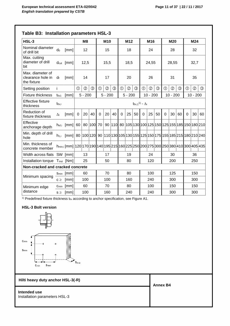
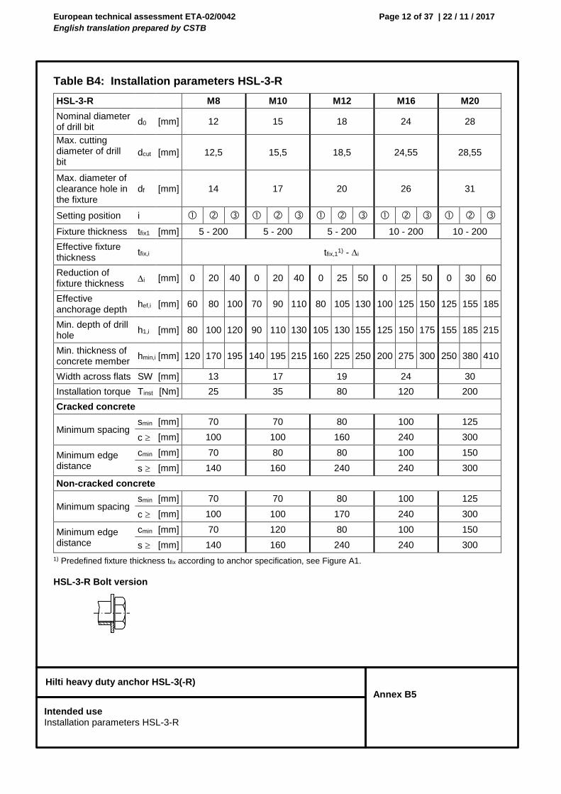
Hilti heavy duty anchor HSL-3(-R)
Annex B2
Table B1: Specifications of intended use
Anchorages subject to: HSL-3 HSL3-G HSL-3-B HSL-3-SK HSL-3-SH
Static and quasi static loading in cracked and non-cracked concrete - hammer drilling and diamond coring
M8-M24 M8-M24 M12-M24 M8-M12 M8-M12
Seismic performance category C1 - hammer drilling and diamond coring
M8-M24 M8-M20 M12-M24 M8-M12 M8-M12
Seismic performance category C2 - hammer drilling only
M10-M20 M10-M20 M12-M20 M10-M12 M10-M12
Anchorages subject to: HSL-3-R HSL-3-GR HSL-3-SKR
Static and quasi static loading in cracked and non-cracked concrete - hammer drilling
M8-M20 M8-M20 M8-M12
Seismic performance category C1 - hammer drilling
M8-M20 M8-M20 M8-M12
Table B2: Drilling technique
Anchorages subject to: HSL-3 HSL3-G HSL-3-B HSL-3-SK HSL-3-SH
Installation torque Tinst [Nm] The torque moment is controlled by the safety cap.
Non-cracked and cracked concrete
Minimum spacing smin [mm] 80 100 125 150
c [mm] 160 240 300 300
Minimum edge distance cmin [mm] 80 100 150 150
s [mm] 240 240 300 300
cmin
cmin hmin
smin
smin
Intended use Installation parameters HSL-3-B
European technical assessment ETA-02/0042
English translation prepared by CSTB
Page 19 of 37 | 22 / 11 / 2017
Hilti heavy duty anchor HSL-3(-R)
Annex B12
Installation instruction
Hole drilling and cleaning
a) Hammer drilling (HD) with manual cleaning (MC):
b) Diamond coring (DD) with flushing and blowing
Anchor setting
Hammer setting, check setting
Anchor torqueing
Use torque wrench
Intended use Installation instruction
European technical assessment ETA-02/0042
English translation prepared by CSTB
Page 20 of 37 | 22 / 11 / 2017
Hilti heavy duty anchor HSL-3(-R)
Annex C1
Table C1: Characteristic values of resistance under tension load in case of static and quasi-static loading HSL-3(-R), HSL-3-G(-GR), HSL-3-B, HSL-3-SH, HSL-3-SK(-SKR)
Performances Characteristic resistance under tension load Design according to CEN/TS 1992-4:2009 or ETAG001, Annex C
European technical assessment ETA-02/0042
English translation prepared by CSTB
Page 22 of 37 | 22 / 11 / 2017
Hilti heavy duty anchor HSL-3(-R)
Annex C3
Table C2: Characteristic values of resistance under shear load in case of static and quasi-static loading HSL-3(-R), HSL-3-G(-GR), HSL-3-B, HSL-3-SH, HSL-3-SK(-SKR)
Performances Characteristic resistance under shear load Design according to CEN/TS 1992-4:2009 or ETAG001, Annex C
European technical assessment ETA-02/0042
English translation prepared by CSTB
Page 24 of 37 | 22 / 11 / 2017
Hilti heavy duty anchor HSL-3(-R)
Annex C5
Table C3: Displacements under tension load in case of static and quasi-static loading - HSL-3(-R), HSL-3-G(-GR), HSL-3-B, HSL-3-SH, HSL-3-SK(-SKR)
Table C4: Displacements under shear load in case of static and quasi-static loading - HSL-3, HSL-3-G, HSL-3-B, HSL-3-SH, HSL-3-SK
Size M8 M10 M12 M16 M20 M24
HSL-3, HSL-3-G, HSL-3-B, HSL-3-SH, HSL-3-SK
Tension load in non-cracked concrete
N [kN] 9,3 11,7 14,3 20,0 27,9 36,7
Corresponding displacement
N0 [mm] 0,1 0,1 0,2 0,3 0,4 0,5
N [mm] 0,2 0,2 0,2 0,4 0,4 0,6
Tension load in cracked concrete
N [kN] 3,6 6,4 10,2 14,3 20,0 26,2
Corresponding displacement
N0 [mm] 0,5 0,5 0,6 0,6 0,7 0,8
N [mm] 1,1 1,1 1,1 1,1 1,1 1,1
HSL-3-R, HSL-3-GR, HSL-3-SKR
Tension load in non-cracked concrete
N [kN] 9,5 13,3 17,1 23,8 33,3 -
Corresponding displacement
N0 [mm] 0,15 0,48 0,41 0,22 0,33 -
N [mm] 0,51 0,51 0,51 0,51 0,51 -
Tension load in cracked concrete
N [kN] 5,7 7,6 11,4 17,1 23,8 -
Corresponding displacement
N0 [mm] 1,17 0,75 2,42 6,37 2,99 -
N [mm] 1,35 0,94 1,66 1,33 1,27 -
Size M8 M10 M12 M16 M20 M24
HSL-3, HSL-3-B, HSL-3-SH, HSL-3-SK
Shear load in cracked and non-cracked concrete
V [kN] 17,8 34,6 51,2 90,6 106,3 116,9
Corresponding displacement
v0 [mm] 3,8 5,2 6,3 8,5 7,3 9,5
v [mm] 5,7 7,8 9,4 12,7 11,0 14,3
HSL-3-G
Shear load in cracked and non-cracked concrete
V [kN] 8,6 23,9 33,9 68,9 88,7 116,9
Corresponding displacement
v0 [mm] 3,7 5,0 6,0 7,9 7,8 9,5
v [mm] 5,6 7,4 9,0 11,9 11,8 14,3
Performances Displacements
European technical assessment ETA-02/0042
English translation prepared by CSTB
Page 25 of 37 | 22 / 11 / 2017
Hilti heavy duty anchor HSL-3(-R)
Annex C6
Table C5: Displacements under shear load in case of static and quasi-static loading - HSL-3-R, HSL-3-GR, HSL-3-SKR
Size M8 M10 M12 M16 M20 M24
HSL-3-R, HSL-3-GR, HSL-3-SKR
Shear load in cracked and non-cracked concrete
V [kN] 19,2 28,0 45,0 74,0 72,3 -
Corresponding displacement
v0 [mm] 12,26 8,13 7,47 41,11 12,44 -
v [mm] 18,4 12,2 11,2 61,7 18,7 -
Performances Displacements
European technical assessment ETA-02/0042
English translation prepared by CSTB
Page 26 of 37 | 22 / 11 / 2017
Hilti heavy duty anchor HSL-3(-R)
Annex C7
Table C6: Characteristic values of resistance under tension load in case of seismic category C1 - HSL-3(-R), HSL-3-G(-GR), HSL-3-B, HSL-3-SH, HSL-3-SK(SKR)
1) In absence of other national regulations 2) Parameter according to TR045 3) Parameter according to CEN/TS 1992-4:2009 4) Pull-out failure is not decisive for design.
Performances Characteristic resistance under seismic actions, seismic category C1 Design according to TR045 or CEN/TS 1992-4:2009
European technical assessment ETA-02/0042
English translation prepared by CSTB
Page 27 of 37 | 22 / 11 / 2017
Hilti heavy duty anchor HSL-3(-R)
Annex C8
Table C6: Continued
1) In absence of other national regulations 2) Parameter according to TR045 3) Parameter according to CEN/TS 1992-4:2009 4) Pull-out failure is not decisive for design.
Performances Characteristic resistance under seismic actions, seismic category C1 Design according to TR045 or CEN/TS 1992-4:2009
European technical assessment ETA-02/0042
English translation prepared by CSTB
Page 28 of 37 | 22 / 11 / 2017
Hilti heavy duty anchor HSL-3(-R)
Annex C9
Table C7: Characteristic values of resistance under shear load in case of seismic category C1 - HSL-3(-R), HSL-3-G(-GR), HSL-3-B, HSL-3-SH, HSL-3-SK(-SKR)
1) In absence of other national regulations 2) Parameter according to TR045 3) Parameter according to CEN/TS 1992-4:2009
Table C10: Characteristic values of resistance under tension load in case of seismic category C2 - HSL-3, HSL-3-G, HSL-3-B, HSL-3-SH, HSL-3-SK
1) In absence of other national regulations 2) Parameter according to TR045 3) Parameter according to CEN/TS 1992-4:2009 4) Pull-out failure is not decisive for design.
Performances Characteristic resistance under seismic actions, seismic category C2 Design according to TR045 or CEN/TS 1992-4:2009
European technical assessment ETA-02/0042
English translation prepared by CSTB
Page 31 of 37 | 22 / 11 / 2017
Hilti heavy duty anchor HSL-3(-R)
Annex C12
Table C11: Characteristic values of resistance under shear load in case of seismic category C2 - HSL-3, HSL-3-G, HSL-3-B, HSL-3-SH, HSL-3-SK
1) In absence of other national regulations 2) Parameter according to TR045 3) Parameter according to CEN/TS 1992-4:2009 4) Pull-out failure is not decisive for design.
Table C15: Characteristic tension resistance under fire exposure for Hilti metal expansion anchor HSL-3(-R), HSL-3-G(-GR), HSL-3-B, HSL-3-SH, HSL-3-SK(-SKR) in cracked and non-cracked concrete
1) Pull-out failure is not decisive for design. 2) In absence of other national regulations the partial safety factor for resistance under fire exposure γM,fi = 1,0 is
Performances Characteristic resistance of tension load resistance under fire resistance
European technical assessment ETA-02/0042
English translation prepared by CSTB
Page 35 of 37 | 22 / 11 / 2017
Hilti heavy duty anchor HSL-3(-R)
Annex C16
Table C16: Characteristic shear resistance under fire exposure for Hilti metal expansion anchor HSL-3(-R), HSL-3-G(-GR), HSL-3-B, HSL-3-SH, HSL-3-SK(-SKR) in cracked and non-cracked concrete
In absence of other national regulations the partial safety factor for resistance under fire exposure γM,fi = 1,0 is
The initial value V0Rk,c,fi of the characteristic resistance in concrete C20/25 to C50/60 under fire exposure may be determined by:
V0Rk,c,fi = 0,25 x V0Rk,c (≤ R90) V0Rk,c,fi = 0,20 x V0Rk,c (R120) with V0Rk,c,fi initial value of the characteristic resistance in cracked concrete C20/25 under normal temperature.
Performances Characteristic resistance of shear load resistance under fire resistance
European technical assessment ETA-02/0042
English translation prepared by CSTB
Page 37 of 37 | 22 / 11 / 2017
Hilti heavy duty anchor HSL-3(-R)
Annex C18
Table C16: Continued
In absence of other national regulations the partial safety factor for resistance under fire exposure γM,fi = 1,0 is
The initial value V0Rk,c,fi of the characteristic resistance in concrete C20/25 to C50/60 under fire exposure may be determined by:
V0Rk,c,fi = 0,25 x V0Rk,c (≤ R90) V0Rk,c,fi = 0,20 x V0Rk,c (R120) with V0Rk,c,fi initial value of the characteristic resistance in cracked concrete C20/25 under normal temperature.
Performances Characteristic resistance of shear load resistance under fire resistance