FBD-NT Press Brake Machine Description General view of machine ............................................................. 2 Functions ..................................................................................... 4 Specifications............................................................................... 8 Machine.................................................................................... 8 Numerical controls ................................................................... 9 List of standard NC functions ................................................... 9 Accessories for voltage change .............................................. 10 Dimensions of machine ........................................................... 11 Backgauge.................................................................................. 12 One-touch stopper fingers ....................................................... 12 Worksheet overhang ............................................................... 13 1
Transcript
FBD-NT Press Brake Machine Description
General view of machine .............................................................2 Functions.....................................................................................4 Specifications...............................................................................8
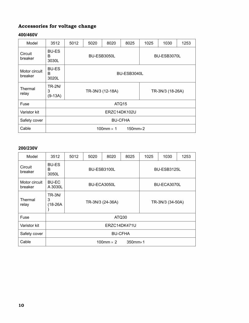
Machine....................................................................................8 Numerical controls ...................................................................9 List of standard NC functions ...................................................9 Accessories for voltage change ..............................................10 Dimensions of machine...........................................................11
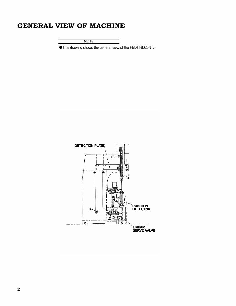
● This drawing shows the general view of the FBDIII-8025NT.
2
3
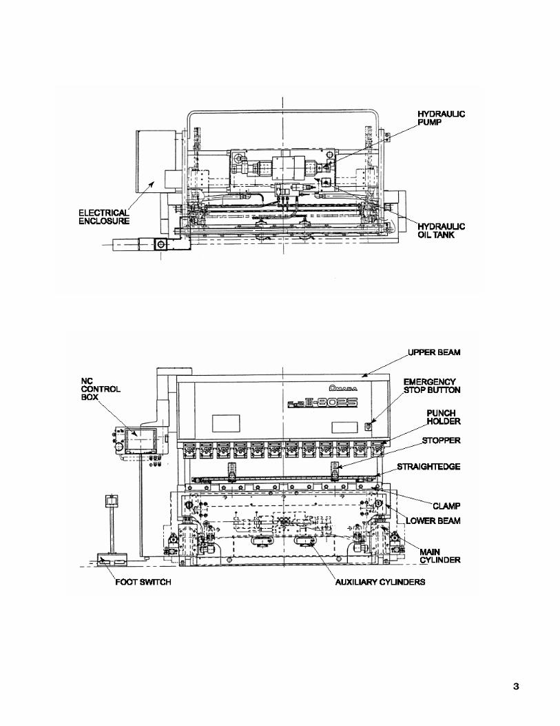
FUNCTIONS This machine is a press brake whose lower beam is hydraulically raised by the linear servo valves at the right and left sides. The UP and DOWN foot pedals are pressed to move up and down the lower beam. The punches are mounted in the punch holders attached to the upper beam, and the dies and die holders are mounted on the lower beam. The worksheet is laid over the dies, supported by hand, and bent by raising the lower beam onto the punches. The bend angle of the worksheet depends on the clearance between the dies and punches. The lower beam is moved up and down by the main cylinders installed on the right and left sides. The auxiliary cylinders are installed at the center of the lower beam to prevent a long worksheet from being bent with a greater angle toward the center (or to keep the clearance between the upper and lower beams uniform in the longitudinal direction). The bend angle is finely adjusted by the right and left linear servo valves, which can also be controlled independently to tilt the lower beam. This tilting function allows the difference in the bend angle between the right and left sides of the worksheet to be compensated for and the worksheet to be offset bent (or bent off the center of the machine). The worksheet can also be pushed against the stoppers of the backgauge to determine its bend position. The machine can be operated from the NC control box.
4
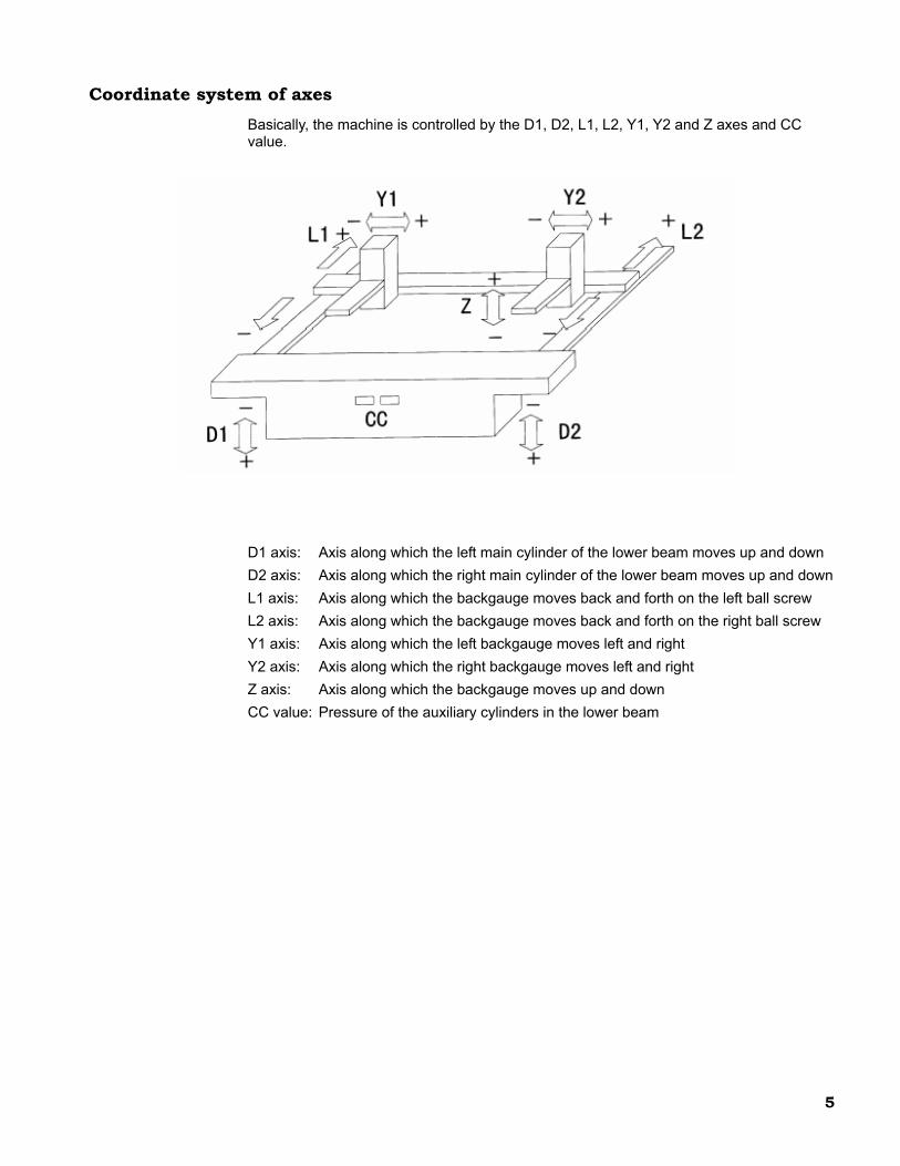
Coordinate system of axes Basically, the machine is controlled by the D1, D2, L1, L2, Y1, Y2 and Z axes and CC value. D1 axis: Axis along which the left main cylinder of the lower beam moves up and down D2 axis: Axis along which the right main cylinder of the lower beam moves up and down L1 axis: Axis along which the backgauge moves back and forth on the left ball screw L2 axis: Axis along which the backgauge moves back and forth on the right ball screw Y1 axis: Axis along which the left backgauge moves left and right Y2 axis: Axis along which the right backgauge moves left and right Z axis: Axis along which the backgauge moves up and down CC value: Pressure of the auxiliary cylinders in the lower beam
5
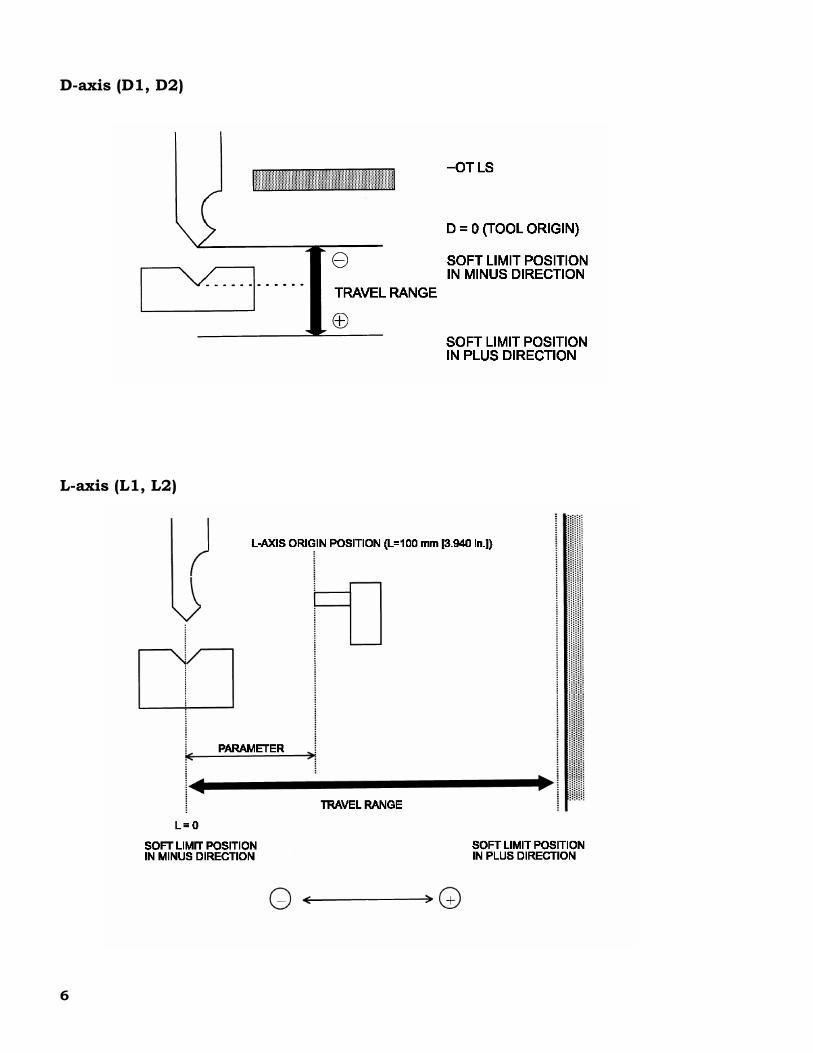
D-axis (D1, D2)
L-axis (L1, L2)
6
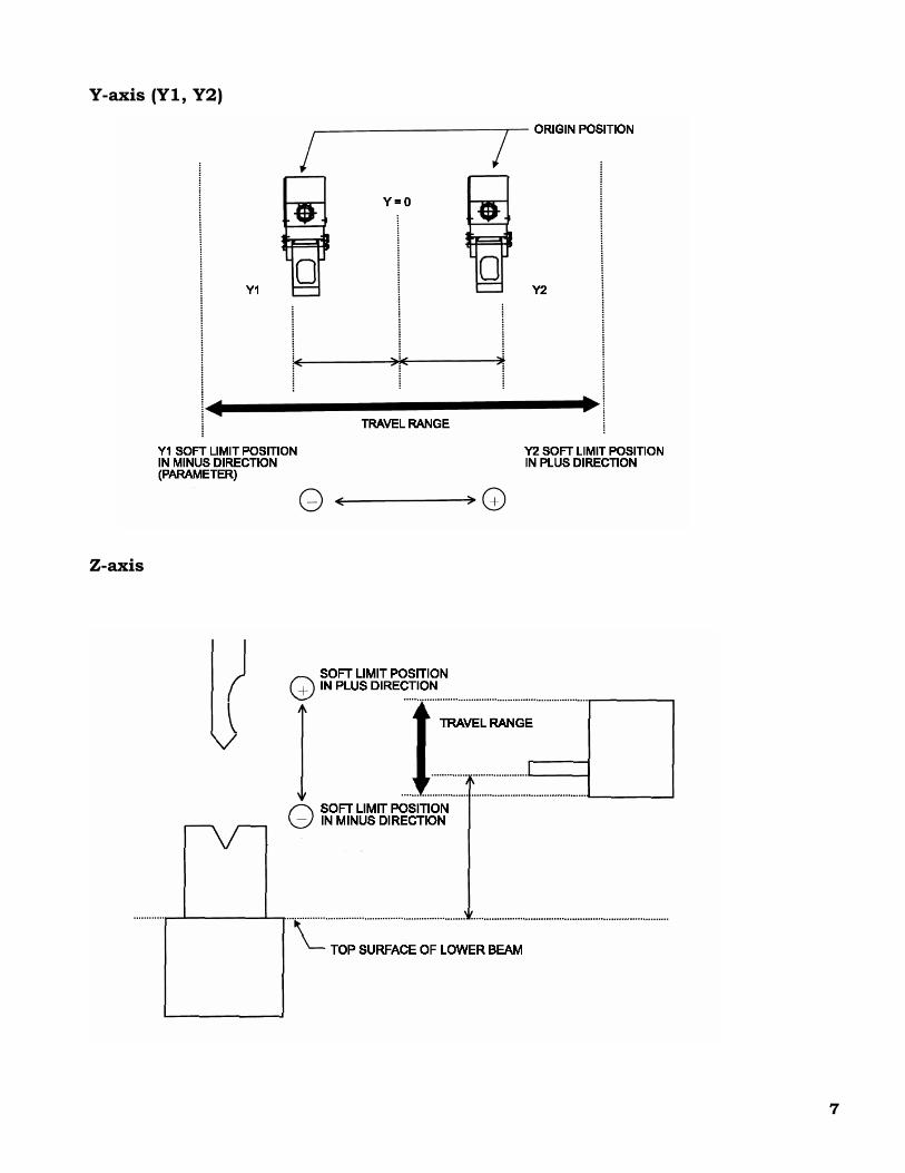
Y-axis (Y1, Y2)
Z-axis
7
SPECIFICATIONS
Machine Model FBD III
3512 FBD III 5012
FBD III 5020
FBD III 8020
FBD III 8025
FBD III 1025
FBD III 1030
FBD III 1253
Maximum bend length mm (in.) 1200 (47.28)
1200 (47.28)
2000 (78.80)
2000 (78.80)
2500 (98.48)
2500 (98.48)
3000 (118.20)
3000 (118.20)
Tonnage capacity metric tons (US
tons)
35 (39)
50 (55)
50 (55)
80 (88)
80 (88)
100 (110)
100 (110)
125 (138)
Vertical stroke of lower beam
mm (in.)
150 (5.91)
Rising speed of lower beam at 50/60 Hz
mm/sec (in./sec)
77/90 (3.03/3.55)
Bending speed of lower beam at 50/60 Hz
mm/sec (in./sec)
8/9 (0.31/0.35)
Lowering speed of lower beam
mm/sec (in./sec)
90* (3.54)
Number of main cylinders (Number of auxiliary cylinders)
2 (2)
Hydraulic pump motor output
kW (HP)
5.5 (7.5)
7.5 (10)
7.5 (10)
7.5 (10)
7.5 (10)
11 (15)
11 (15)
11 (15)
Hydraulic unit tank capacity
liters (US gal)
90 (23.7)
90 (23.7)
70 (18.4)
70 (18.4)
70 (18.4)
90 (23.7)
90 (23.7)
90 (23.7)
Machine weight metric tons (US
tons)
3.0 (3.3)
3.2 (3.5)
4.0 (4.4)
5.0 (5.5)
6.2 (6.8)
6.5 (7.2)
7.6 (8.4)
8.8 (9.7)
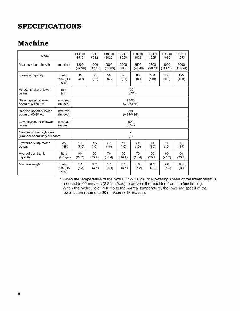
* When the temperature of the hydraulic oil is low, the lowering speed of the lower beam is reduced to 60 mm/sec (2.36 in./sec) to prevent the machine from malfunctioning. When the hydraulic oil returns to the normal temperature, the lowering speed of the lower beam returns to 90 mm/sec (3.54 in./sec).
8
Numerical controls Position command method Incremental
Number of control axes Simultaneous 8-axis automatic operation (D1, D2, L1, L2, Y1, Y2, Z1, Z2)
D-axis 0.001 mm (0.0001 in.) Least input increment L-axis 0.01 mm (0.001 in.)
Storage tools Stored as AMADA standard tools
Display method 14.1” color LCD
D-axis 1 to 8 mm/sec (0.039 to 3.03 in./sec) Feeding speed
L-axis 30000 mm/min (1181.10 in./min)
D-axis 0 to 150.00 mm/sec (0 to 5.9055 in.) Movable range
L-axis 2 to 501 mm (0.081 to 19.678 in.), –OT, +OT soft LS
Power 200/230/400/460 V
Temperature 0 to 40°C (32 to 104°F) when operating Environment
Humidity 75% (relative humidity), non-condensing
LIST OF STANDARD NC FUNCTIONS • Offset bending • Automatic calculation • Angle compensation • Playback function • Pullback function • All set input • Idle timer • Slowdown timer • Multiple lower limits (stepless) • Backgauge operation selection (automatic) • Elongation compensation value table • Angle compensation value table • Quantity setup • Stroke counter • Clock function • Integrating timer • Tool allowable pressure check function • Optional input • Elongation compensation function
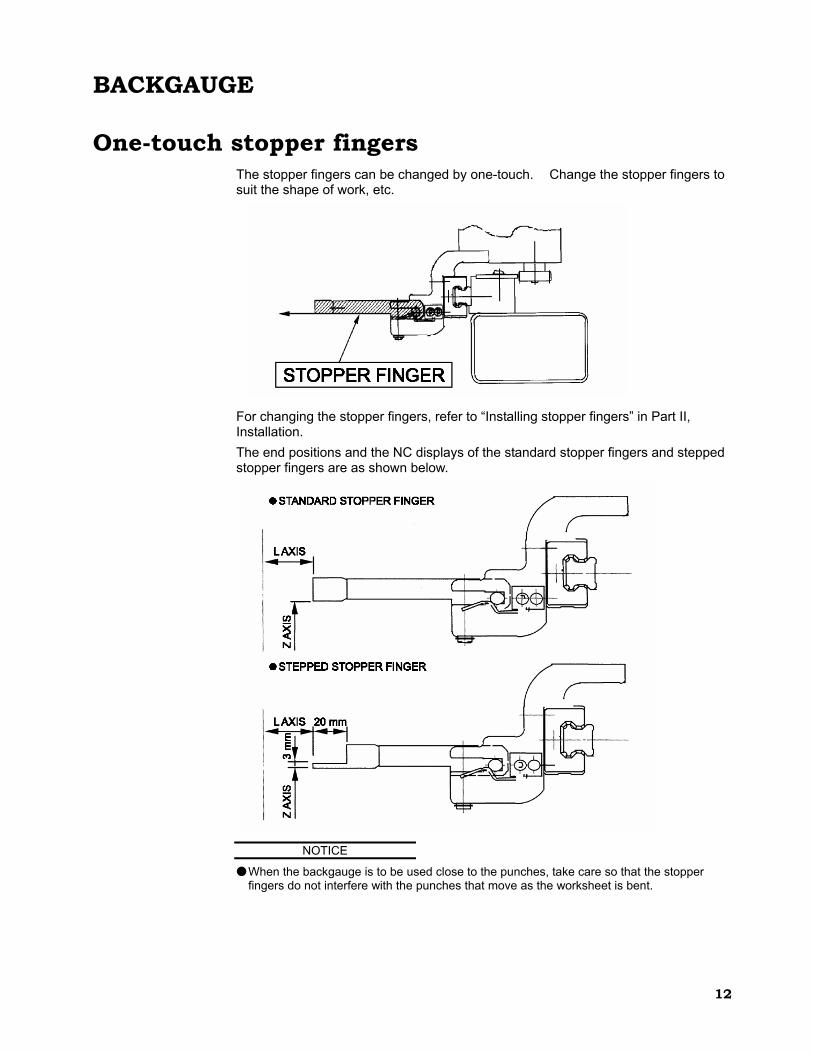
One-touch stopper fingers The stopper fingers can be changed by one-touch. Change the stopper fingers to suit the shape of work, etc.
For changing the stopper fingers, refer to “Installing stopper fingers” in Part II, Installation. The end positions and the NC displays of the standard stopper fingers and stepped stopper fingers are as shown below.
NOTICE
● When the backgauge is to be used close to the punches, take care so that the stopper fingers do not interfere with the punches that move as the worksheet is bent.
-1
I12
I-2
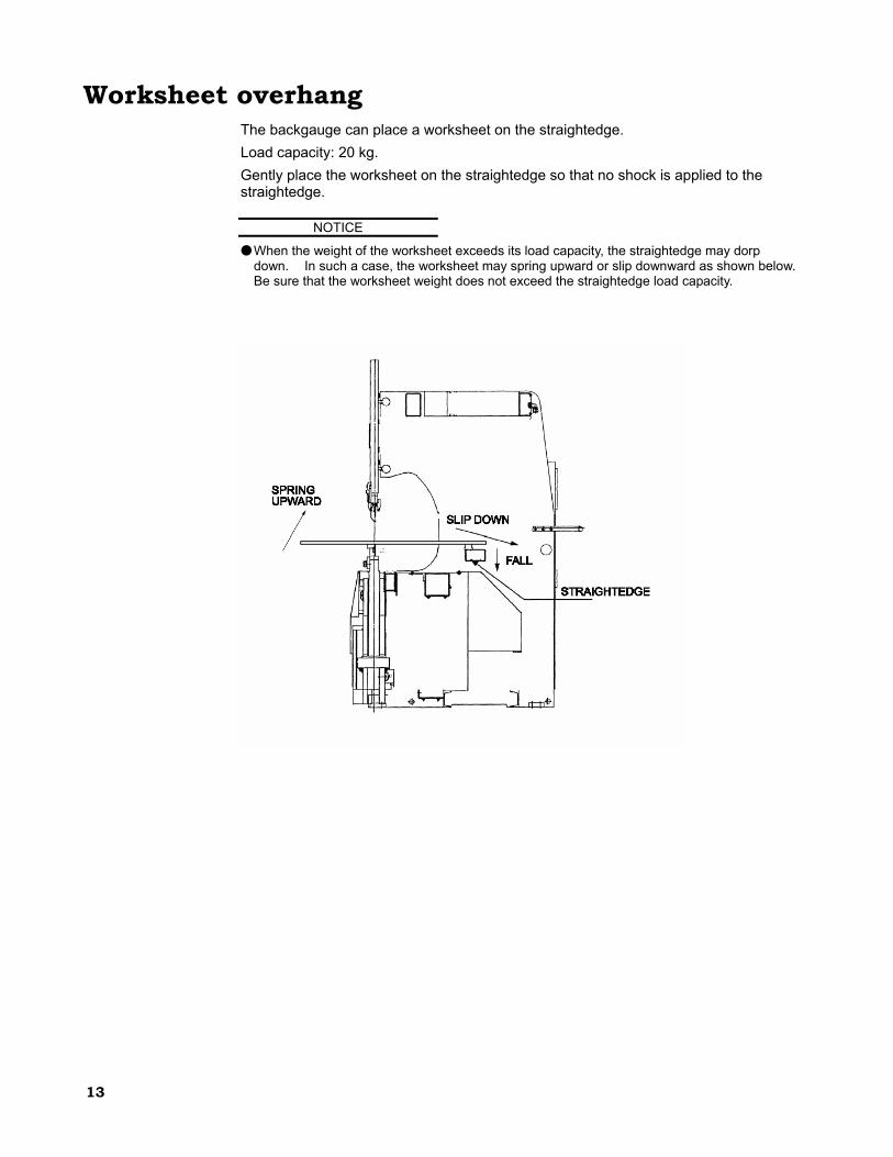
Worksheet overhang The backgauge can place a worksheet on the straightedge. Load capacity: 20 kg. Gently place the worksheet on the straightedge so that no shock is applied to the straightedge.
NOTICE
● When the weight of the worksheet exceeds its load capacity, the straightedge may dorp down. In such a case, the worksheet may spring upward or slip downward as shown below. Be sure that the worksheet weight does not exceed the straightedge load capacity.