112
N9967V3 4/04 Rev. A FBII Security System Security System Security System Security System OMNI ® 624 Version 2.X Installation and Setup Guide
N9967V3 4/04 Rev. A
FBII Security SystemSecurity SystemSecurity SystemSecurity System
OMNI®624
Version 2.X
Installation and Setup Guide
ii
THANK YOU for your purchase of the OMNI624 Security System.
The purpose of this manual is to give you a brief overview of the OMNI®624 control panels, and provides instructions for installing a basic system. Honeywell is always available to serve YOU. Our SALES and TECHNICAL SUPPORT staff are available to assist you in any way possible.
World Wide Web Address ..........................................http://www.honeywell.com/security FAX ...............................................................................................................516-921-4327
Sales Inside the United States .....................................................................800-645-5430 Outside the United States...................................................................516-921-8666
Technical Support: (8 a.m.-8 p.m. E.S.T.) Inside the United States .....................................................................800-645-7492 Outside the United States...................................................................516-921-8666
Before you call Technical Support, PLEASE be sure you: • Check the wiring diagram and verify your connections. • Check all fuses. • Assure that the transformer and backup battery voltages are supplying the proper voltage
levels. • Verify your programming information. • Read this manual thoroughly. • Consult the Troubleshooting Section of this manual. • Note the proper model number of this product, and the version level (if known) along with any
documentation that came with the product. • Have your company name and telephone number ready.
This information will allow us to service you more quickly and effectively. Please, remember to BE PATIENT while waiting on the telephone; your call will be answered as soon as possible.
FOR YOUR CONVENIENCE, a separate Programming Guide is included with this manual. It provides space for listing entries for each programming question.
NEW FEATURES OF VERSION 2.X • Wireless Jamming Detection Processing • Crystal Controlled Real-Time Clock • Silent Zone, RF Jam, and Keypad Tamper
Triggers
• Keypad Tamper to Detect Keypad Removal • Activate Dial Delay if Armed-Stay Option • Keypad Supervision and Zone Unbypass
Logged

iii
Table of Contents • • • • • • • • • • • • • • • • • • • • • • • • • • • • • • • • • • • • • • • • • • •
SECTION 1 – CENTRAL STATION REPORTING FORMATS....................................................... 1–1 System Features .................................................................................................................................. 1–1 Special Notes........................................................................................................................................ 1–2
SECTION 2 – SYSTEM WIRING AND HOOKUP .............................................................................. 2–1 System Wiring Diagram ...................................................................................................................... 2–1 Terminal Connections.......................................................................................................................... 2–2 Auxiliary Device Current Draw Worksheet........................................................................................ 2–5 Wiring Information for Keypads & Other Devices............................................................................. 2–6
SECTION 3 – PC BOARD AND KEYPAD MOUNTING ................................................................... 3–1 Mounting the OMNI624 PC Board ..................................................................................................... 3–1 Mounting the RF Expander Module ................................................................................................... 3–2 Mounting the Zone Expander Module ................................................................................................ 3–2 Keypad Mounting Instructions ........................................................................................................... 3–2
SECTION 4 – SYSTEM CONFIGURATION ....................................................................................... 4–1 Partitioning .......................................................................................................................................... 4–1 Hardwire Zones and Zone Expansion Module.................................................................................... 4–1 Wireless Transmitters ......................................................................................................................... 4–2 Relay/Trigger Outputs......................................................................................................................... 4–3 Paging Feature..................................................................................................................................... 4–4
SECTION 5 – SYSTEM OPERATION.................................................................................................. 5–1 Power Up/System Reset....................................................................................................................... 5–1 Keypads ................................................................................................................................................ 5–1 Keypad Sounder................................................................................................................................... 5–3 Keypad Backlight Timer...................................................................................................................... 5–4 Keypad Addressing .............................................................................................................................. 5–5 Arming the System .............................................................................................................................. 5–5 User Code Programming ..................................................................................................................... 5–8 User Deletion ..................................................................................................................................... 5–10 Keypad Emergency Conditions ......................................................................................................... 5–10 Quick Command Modes..................................................................................................................... 5–11
SECTION 6 – SYSTEM PROGRAMMING .......................................................................................... 6–1 Programming Methods ........................................................................................................................ 6–1 System Default..................................................................................................................................... 6–1 Keypad Programming.......................................................................................................................... 6–2 Installer Modes Summary ................................................................................................................... 6–5 Data Entry via Keypads ...................................................................................................................... 6–9 Summary of System Programming ................................................................................................... 6–11 Programming Submode 1: SYSTEM OPTIONS............................................................................... 6–11 Programming Submode 2: ZONE PROGRAMMING / REPORT CODES ....................................... 6–45 Programming Submode 3: WIRELESS TRANSMITTER PROGRAMMING.................................. 6–51
iv
Programming Submode 4: DESCRIPTOR PROGRAMMING ......................................................... 6–53 SECTION 7 – SUMMARY OF KEYPAD FUNCTIONS ..................................................................... 7–1
User Functions..................................................................................................................................... 7–1 Installer Modes .................................................................................................................................... 7–2
SECTION 8 – CENTRAL STATION REPORTING FORMATS....................................................... 8–1 General Information ............................................................................................................................ 8–1 Standard (3x1 or 4x1) .......................................................................................................................... 8–1 Extended (3x1 Ext. or 4x1 Ext.) .......................................................................................................... 8–2 Partial Extended (3x1 Part. Ext. or 4x1 Part. Ext.) ........................................................................... 8–2 3x2 or 4x2 ............................................................................................................................................. 8–3 FBII Superfast (4x3x1) ........................................................................................................................ 8–3 ADEMCO 4x1 Express ........................................................................................................................ 8–4 ADEMCO 4x2 Express ........................................................................................................................ 8–4 ADEMCO Contact ID .......................................................................................................................... 8–5
SECTION 9 – TROUBLESHOOTING.................................................................................................. 9–1 SECTION 10 – REGULATORY/LIMITATIONS STATEMENTS................................................... 10–1 SECTION 11 – CE LOW VOLTAGE DIRECTIVE............................................................................ 11–1
v
Conventions Used in This Manual • • • • • • • • • • • • • • • • • • • • • • • • • • • • • • • • • • • • • • • • • • •
Before you begin using this manual, it is important that you understand the meaning of the following symbols (icons) and text note.
UL These notes include specific information that must be followed if you are installing this system for a UL Listed application.
These notes include information that you should be aware of before continuing with the installation, and which, if not observed, could result in operational difficulties.
!
This symbol indicates a critical note that could seriously affect the operation of the system, or could cause damage to the system. Please read each warning carefully. This symbol also alerts the user to the possibility of physical harm if instructions are not followed as written.
Note: These text notes are provided throughout the manual to provide informative information and
shortcut tips for the installer.

vi

1–1
S E C T I O N 1
Introduction • • • • • • • • • • • • • • • • • • • • • • • • • • • • • • • • • • • • • • • • • • •
System Features The OMNI®624 is a state-of-the-art microprocessor-based control/communicator that provides 2 partitions and supports both hardwire and wireless zones. Programming can be performed through any of the compatible keypads, or the system can be uploaded and downloaded remotely using the Compass Downloader Software. Additionally, the software can be programmed to control remote actions, such as arming, disarming, bypassing, etc. Programming options are stored in an Electrically Erasable Programmable Read Only Memory (EEPROM). The EEPROM is nonvolatile, meaning that programmed instructions will not be lost in the event of a loss of power. Features of the OMNI624 include: • 2 independent partitions • Up to 24 zones that may be comprised of a
combination of hardwire and wireless or wireless zones
• 6 hardwire zones (all fully programmable, including keyswitch), expandable to 8 additional hardwire zones using optional plug-in OMNIEXP8 Expansion module
• Hardwire zones can be configured as standard or double-balanced, or can be set for zone doubling (providing up to 24 hardwire zones if zone expander is used)
• Up to 24 wireless protection zones plus up to 8 wireless keys
• Cross-zoning capability • 32 User Codes (either 4-digit or 6-digit codes
can be used) • Up to 12 keypads (OMNI-LCD, OMNI-LCD-US,
XK7LC, OMNI-KP, OMNI-KP-US)
• OMNI-LCD, OMNI-KP, and XK7LC keypads are not for sale in the USA.
• XK108 keypads may also be used; however, the system can only have XK108 type keypads attached and the system must be set up as having one partition.
• Keypad programming and remote programming via PC and modem
• 3 emergency keypad conditions (Panic, Fire, & Auxiliary)
• 128 Event History Log (alarms, troubles, low battery, bypasses, central station (CS) test, openings & closings) and keypad events
• 20 programmable relay outputs (using optional XL4705 modules)
• 4 built-in programmable trigger outputs (2 triggers if relay module is used)
• Real-time clock (displays time & date via LCD keypad) with reminder when clock needs to be set
• CS test timer by event, time or both (1 hour, 1, 7, 27, 60, 90 Days)
• Customer control of Chime mode and Pager mode
• Quick Arming, Quick Bypass, and Quick Force Arming
• CS reporting by zone • False alarm prevention features: Crossed
Zones, Exit Error, Recent Close, Swinger Shutdown
• Cancel Code & System Stabilization during power-up
• Arming by keyswitch in Away or Stay mode • Keypad Tamper/Lockout with optional CS
reporting • Restore transmission options: After Loop or
After Bell
OMNI624 Installation and Setup Guide
1–2
• Upload/download and remote commands • 3 methods of uploading/downloading: PC,
operator-initiated, and unattended • Paging (audio format) capabilities • Auto-arming at a specific time of day with
capability to arm in either Away, Stay, or Instant modes
• Dual entry timers
• Fire zone reset through keypad • Glassbreak reset through keypad • Bell Test, Low Battery Test, AC loss and
communications failure • Input power: 16.5VAC, 25VA; 12VDC, 4-7AH • Output power: 12VDC, 500mA • Bell output power: 12VDC, 1A
Special Notes
!
IMPORTANT - Failure to install and program this unit in accordance with the UL requirement is a violation of the listing mark. For more information on UL Listings, contact Underwriters Laboratories, Progress Department, 333 Pfingsten Road, Northbrook, IL 60062.
UL Listings The OMNI624 is the Residential (Household) version of the control panel, and has been Listed by Underwriters Laboratories for the following applications:
• UL 1023 Household Burglary • UL 985 Household Fire Warning
FCC Registration Number: 5GBUSA-44003-AL-E
References to Programming Questions
Programming questions are grouped into 4 installer programming submodes, as follows: 1 – System Options 2 – Zone and Report Code Programming 3 – Wireless Zone/Keyfob Programming 4 – Zone Descriptor Programming
Throughout this manual, programming question references without a submode designation pertain to questions in submode 1 (system options). Programming questions for other submodes include the appropriate submode number.

2–1
S E C T I O N 2
System Wiring and Hookup • • • • • • • • • • • • • • • • • • • • • • • • • • • • • • • • • • • • • • • • • • •
System Wiring Diagram
OMNI624 Installation and Setup Guide
2–2
SYSTEM STABILIZATION MODE: When powering up a system that was previously armed when power was removed, the system will enter a 2-minute stabilization period. This 2-minute interval is used to allow motion detectors to stabilize. “PLEASE STAND BY” and “POWER UP DELAY” are displayed on the OMNI-LCD, OMNI-LCD-US and XK7LC keypads. “PL” is displayed on the OMNI-KP and OMNI-KP-US keypads, and the Armed LEDs on both types of keypads are lit. All LEDs on the XK108 keypad are lit.
Terminal Connections 1 & 2 — TRANSFORMER: Connect the 16.5VAC 25VA transformer, utilizing 18AWG (1mm dia.) or
larger wire at a distance not to exceed 15 feet (4.5m) from the panel, to an unswitched source of AC mains power (120 or 220VAC). The system can supply up to 1.8 amps of total current. For US installations, use an ADEMCO No. 1321 transformer or for Canadian installations, use an ADEMCO No. 1321CN transformer. For all other installations, use a transformer that complies with the above specifications. Do not use any other rating transformer, as this may result in improper operation or damage to the unit. The “AC/LOW BAT” keypad LED remains ON while AC power is present. If an AC loss occurs, the “AC/LOW BAT” LED turns off immediately. If AC power remains OFF for 15 minutes, the system pulses the keypad buzzer and transmits a power-loss message to the central station, if programmed to do so. THE KEYPAD BUZZER CAN BE SILENCED by entry of any valid user code. When AC restores, the “AC/LOW BAT” LED lights immediately, and a Restore code is reported, if programmed.
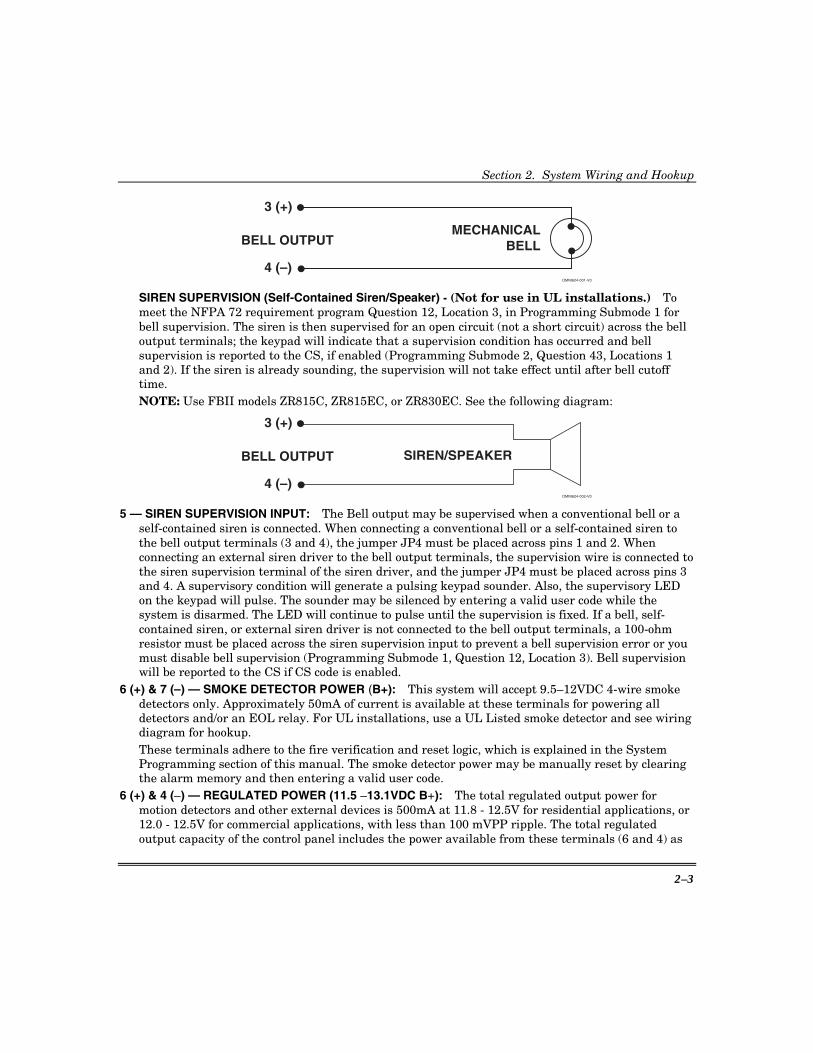
3(+) & 4(–) — BELL OUTPUT: The total output power available for sounding devices is 1 amp (650 mA for UL installations) at 11.5 - 13.1VDC. These terminals will deliver CONSTANT output on BURGLARY, AUDIBLE PANIC, and BELL TEST. On a FIRE condition, a PULSED or TEMPORAL output can be generated. There are separate bell cutoff times programmable for burglary and fire conditions within the programming sequence. For UL Household Fire Warning System installations, the speaker must be mounted indoors for best audibility. Also, for UL installations, use only one speaker. NOTE: Before connecting sounding devices, please consult their specifications for proper current draw. Otherwise, the bell fuse (F1) may be blown. NFPA 72 REQUIREMENT: All the interconnecting pathways (cable, wire, etc.) between the alarm system initiating device (control panel) and the signaling device (bell, speaker, siren, etc.) shall be monitored for an occurrence of an open circuit, which prevents the normal operation of the system. An occurrence of an open circuit shall be indicated by a distinctive trouble signal.
BELL SUPERVISION (Bell) - To meet the NFPA 72 requirement, program Question 12, Location 3, in Programming Submode 1 for bell supervision. The bell is then supervised for an open circuit (not a short circuit) across the bell output terminals; the keypad will indicate that a bell supervision condition has occurred and fire trouble is reported to the CS if enabled. If the bell is already ringing, the supervision will not take effect until after bell cutoff time. Refer to the following diagrams:
Section 2. System Wiring and Hookup
2–3
3 (+)
OMNI624-001-V0
MECHANICALBELLBELL OUTPUT
4 (–)
SIREN SUPERVISION (Self-Contained Siren/Speaker) - (Not for use in UL installations.) To meet the NFPA 72 requirement program Question 12, Location 3, in Programming Submode 1 for bell supervision. The siren is then supervised for an open circuit (not a short circuit) across the bell output terminals; the keypad will indicate that a supervision condition has occurred and bell supervision is reported to the CS, if enabled (Programming Submode 2, Question 43, Locations 1 and 2). If the siren is already sounding, the supervision will not take effect until after bell cutoff time. NOTE: Use FBII models ZR815C, ZR815EC, or ZR830EC. See the following diagram:
3 (+)
OMNI624-002-V0
SIREN/SPEAKERBELL OUTPUT
4 (–)
5 — SIREN SUPERVISION INPUT: The Bell output may be supervised when a conventional bell or a self-contained siren is connected. When connecting a conventional bell or a self-contained siren to the bell output terminals (3 and 4), the jumper JP4 must be placed across pins 1 and 2. When connecting an external siren driver to the bell output terminals, the supervision wire is connected to the siren supervision terminal of the siren driver, and the jumper JP4 must be placed across pins 3 and 4. A supervisory condition will generate a pulsing keypad sounder. Also, the supervisory LED on the keypad will pulse. The sounder may be silenced by entering a valid user code while the system is disarmed. The LED will continue to pulse until the supervision is fixed. If a bell, self-contained siren, or external siren driver is not connected to the bell output terminals, a 100-ohm resistor must be placed across the siren supervision input to prevent a bell supervision error or you must disable bell supervision (Programming Submode 1, Question 12, Location 3). Bell supervision will be reported to the CS if CS code is enabled.
6 (+) & 7 (–) — SMOKE DETECTOR POWER (B+): This system will accept 9.5–12VDC 4-wire smoke detectors only. Approximately 50mA of current is available at these terminals for powering all detectors and/or an EOL relay. For UL installations, use a UL Listed smoke detector and see wiring diagram for hookup. These terminals adhere to the fire verification and reset logic, which is explained in the System Programming section of this manual. The smoke detector power may be manually reset by clearing the alarm memory and then entering a valid user code.
6 (+) & 4 (–) — REGULATED POWER (11.5 –13.1VDC B+): The total regulated output power for motion detectors and other external devices is 500mA at 11.8 - 12.5V for residential applications, or 12.0 - 12.5V for commercial applications, with less than 100 mVPP ripple. The total regulated output capacity of the control panel includes the power available from these terminals (6 and 4) as

OMNI624 Installation and Setup Guide
2–4
well as the power used by the keypads (23 [+] and 20 [–]) and smoke detectors (7 [–] and 6 [+]). Therefore, to determine the total power available from these terminals, subtract the power consumed by the keypads and smoke detectors. NOTE: For UL installations, total current cannot exceed 180mA including the keypads connected to terminals 20 through 23.
ZONE INFORMATION (HARDWIRED ZONES): 8 (+) & 9 (–) Zone 1 [Default = DELAY] 13 (+) & 12 (–) Zone 4 [Default = INSTANT] 10 (+) & 9 (–) Zone 2 [Default = INTERIOR] 14 (+) & 15 (–) Zone 5 [Default = INSTANT] 11 (+) & 12 (–) Zone 3 [Default = INSTANT] 16 (+) & 15 (–) Zone 6 [Default = INSTANT]
Normally-closed devices may be wired in series; normally open devices may be wired in parallel. A 2.2k-ohm end-of-line resistor can be installed on all zones. (Refer to the wiring diagram.) The standard loop response time is 280mS on all zones. The factory default values for each zone are listed in the table above; however, any zone can be programmed for the following types: delay, perimeter, interior, fire, 24-hr. alarm, or 24-hr. trouble. Further explanation of the zone types can be found in the System Programming section of this manual. See the “Hardwired and Zone Expansion Module” paragraph in Section 4: System Configurations for information on zone doubling (to increase the number of available hardwire zones) and the use of double-balanced zones. NOTE: Loop response is defined as the minimum time required for a fault to trip a zone.
RF RECEIVER — ZONE INFORMATION (WIRELESS ZONES): Up to 24 wireless zones can be used if the ZR401, ZR402EU, or OMNI-RF Wireless Expansion Module is installed. The maximum number of zones (24) includes the 6 basic wired zones, wired zones using the expansion module, and the wireless zones. Compatible ADEMCO 5800 Series or FBII ZR500 Series wireless devices must be used. See the “Wireless Zones” paragraph in Section 4: System Configuration for more information on using wireless zones and for a list of compatible transmitters. The ZR402EU, OMNI-RF Wireless Expansion Modules, and ZR500 Series wireless devices have not been evaluated by UL.
20 (BLK), 21 (YEL), 22 (GREEN) & 23 (RED) — KEYPADS: Up to 12 keypads may be wired to these terminals. The connections are as follows: 20 (BLACK = negative), 21 (YELLOW = data in), 22 (GREEN = data out) and 23 (RED = positive power). Refer to the table in the “Auxiliary Device Current Draw Worksheet” paragraph of this section to obtain keypad current draw information. NOTE: In some installations, it may be necessary to use shielded wire to prevent radio frequency interference.
24 — EARTH GROUND: Connect this grounding lug to a cold-water pipe utilizing 18AWG (1mm dia.) wire at a distance of no greater than 15 feet (4.5m). Use a noncorrosive metal strap firmly secured to the pipe to which the lead is electrically connected and secured. If the premises pipes terminate in PVC, this terminal must be connected to a 6-foot (2m) grounding rod.
25 (BRN), 26 (GRAY), 27 (GREEN) & 28 (RED) — TELEPHONE LINE: Connect the RJ31X cord as follows: 25 (BROWN = Home Ring), 26 (GRAY = Home Tip), 27 (GREEN = Telco Tip), 28 (RED = Telco Ring). Insert the plug into an USOCRJ31X Jack (or a CA31A Jack for Canadian installations). The system should not be connected to party lines or coin-operated phones.
!
If this control panel will be used for uploading, downloading, or remote-command applications, the telephone line connected to the control panel must not be shared with a fax machine or modem. Furthermore, this device should not be connected to a phone line that has Call Waiting, unless the Call Waiting Interrupt numbers are programmed into the panel dialing sequence.

Section 2. System Wiring and Hookup
2–5
BACKUP BATTERY: The RED (+) and BLACK (–) flying leads must be connected to a 12VDC 4–7AH lead acid battery, to serve as backup power in the event of AC loss. A battery test occurs approximately every minute. Low-battery condition occurs at nominal 11VDC. The keypad AC/LOW BAT LED and buzzer will pulse slowly when a low-battery condition is detected. The system reports this condition to the CS if programmed to do so. There is also an option that prevents the system from arming if a low battery has been detected (see Question 14, L2). Battery restoral will occur within 4 minutes, at the next battery test. The buzzer may be silenced by entry of any valid user code. NOTE: For UL installations, use two 4AH batteries connected in parallel.
TRIGGER/RELAY OUTPUTS: The control panel has four built-in programmable trigger outputs. In addition, up to four XL4705 Relay Modules can be connected, providing 20 additional programmable relay outputs. If the Relay Modules are used (enable modules in Programming Submode 1, Question 12, L2), then built-in triggers 3 and 4 are no longer used as trigger outputs, but serve as clock and data inputs for the relay modules. See Programming Submode 1, Questions 32–43, for valid trigger/relay types and programming. NOTE: In order to connect devices to the triggers, use connector XL4612TC (trigger cable). Connect to terminal P1 VBELL to obtain a POSITIVE reference point. Triggers 1, 2, 3, and 4 (3 and 4 when not using XL4705) will go to a negative ground potential when active. For UL installations, the trigger outputs shall be connected to devices rated to operate over the range from 10.1–14.0VDC at 50mA.
Auxiliary Device Current Draw Worksheet
DEVICE CURRENT DRAW
FOR EACH NUMBER OF UNITS
TOTAL CURRENT FOR ALL UNITS
Control Panel 65mA 1 65mA OMNI-LCD/OMNI-KP-US (Standby/Alarm)
40mA/180mA
XK7LC 65mA OMNI-KP/OMNI-KP-US (Standby/Alarm)
40mA/70mA
XK108 30mA PIR ** Smoke Detector ** Glassbreak Detector ** ** **
TOTAL CURRENT FOR ALL DEVICES =(500mA max.)***
** If the system is using devices such as PIR's, smoke detectors, etc., refer to the specifications for that particular device's current draw. If the total current draw for all devices exceeds 500mA, use an additional power supply. *** For UL installations, do not exceed 180mA.
NFPA, UL, and the California State Fire Marshal require the backup battery to provide power for 24 hours. The maximum aux. power will vary by the ampere/hour rating of the battery used:5AH = 95mA; 7AH = 180mA; 8AH = 210mA.

OMNI624 Installation and Setup Guide
2–6
Wiring Information for Keypads & Other Devices
KEYPADS & OTHER DEVICES If single or multiple devices are connected on a single 4-wire or 2-wire run ("daisy chained") to the control terminals, do the following:
Determine the current drawn by the unit(s) connected to the single-wire run, then refer to the Wiring Run Table below to determine the maximum wire length that can be safely used for each wire size.
In some cases, the total current drawn may result in a value not shown in the table. For example, if you plan to use #22 gauge (0.64mm) wire and the total current drawn is 400mA (a value between 300mA and 500mA), the maximum wire length you should use is approximately 65 ft. or 20m (a length between 50 and 80 ft or 15m and 24m). Other maximum wire lengths for values of current not shown in the table can be calculated in a similar manner.
Maximum wire lengths for a device that is "home run" to the control can also be determined from the table, based on the current draw of that device alone.
Wiring Run Table For Devices Drawing Power From Terminals 23 (+) & 20 (–)
TOTAL CURRENT DRAWN BY ALL UNITS ON A SINGLE WIRE RUN WIRE SIZE
50mA or less 100mA 300mA 500mA
#22 (0.64mm) 500 ft. (152m) 250 ft. (76m) 80 ft. (24m) 50 ft. (15m)
#20 (0.8mm) 750 ft. (229m) 380 ft. (116m) 130 ft. (40m) 80 ft. (24m)
#18 (1mm) 1300 ft. (396m) 650 ft. (198m) 220 ft. (67m) 130 ft. (40m)
#16 (1.3mm) 2000 ft. (610m) 1000 ft. (305m) 330 ft. (100m) 200 ft. (70m)
Examples:
1. What is the maximum distance from the control panel for one keypad drawing 30mA using #20 gauge (0.8mm dia.) wire?
Using the table above, the keypad can be placed no farther than 750 ft. (230m) away from the panel (50mA or less).
2. What is the maximum distance for 5 smoke detectors drawing 0.25mA (50µA each) using #22 gauge (0.64mm dia.) wire connected in a single-wire run?
Using the table above, the farthest smoke detector can be placed no more than 500 ft. (150m) away from the panel.

3–1
S E C T I O N 3
PC Board and Keypad Mounting • • • • • • • • • • • • • • • • • • • • • • • • • • • • • • • • • • • • • • • • • • •
Mounting the OMNI624 PC Board NOTE: The door of the metal cabinet may be removed to make it easier to install the control panel. Remove the door as follows:
1. With the cabinet laying on a flat surface, swing open the door to its full-open position.
2. Slide the door out of its retaining slots in the cabinet and store in a safe place. BEFORE MOUNTING PRINTED CIRCUIT BOARD, BE CERTAIN THAT APPROPRIATE METAL KNOCKOUTS HAVE BEEN REMOVED FROM THE METAL CABINET. DO NOT ATTEMPT TO REMOVE THE KNOCKOUTS AFTER CIRCUIT BOARD HAS BEEN INSTALLED.
3. Insert top of circuit board into slots at top of cabinet. Make sure that circuit board rests in slots as indicated in the diagram shown below.
4. Swing base of circuit board onto the raised cabinet tabs.
5. Secure the sides of the PC board to the enclosure using the 2 screws provided.
CABINET
DETAIL CANTENNA AND GROUNDING LUG INSTALLATION
ANTENNAMOUNT
(2 PLACES)
ANTENNA(2)
SCREW(2)
BOARDSUPPORTING
SLOTS
RCVR BRD
DETAIL ASIDE VIEWOF BOARD
SUPPORTING SLOTS
DETAIL BSIDE VIEW
OF MOUNTINGSCREW
GROUNDINGLUG
(2)
pcb_mount-006-V0
CIRCUIT BOARD
CABINET
CONTROL CIRCUIT BOARD
++
CONTROL CIRCUIT BOARD
RFRECEIVER
ANTENNAS
(INSERT INRIGHT-HANDTERMINALS)
RFRECEIVER

OMNI624 Installation and Setup Guide
3–2
Mounting the RF Expander Module 1. Mount the receiver board on top of the
control PC board as shown in the diagram at right.
2. Insert grounding lugs (supplied) into the left-hand terminals of the antenna blocks and secure them to the cabinet with the screws provided.
3. Insert the receiver's antennas through the top of the cabinet into the blocks' right-hand terminals. Tighten screws.
BOARD
ZR401/ZR402EU/OMNI-RFRF RECEIVER
OM
NI6
24-0
04-V
1
Mounting the Zone Expander Module 1. Mount the zone expander board onto the control PC board pins where shown in the diagram below. 2. Connect zone wiring as shown on the wiring diagram earlier in this manual.
BOARD
OMNIEXP 8HARDWIRE ZONE EXPANDER
OM
NI6
24-0
05-V
1
Keypad Mounting Instructions The security system is compatible with the following addressable keypads: • LCD (alpha) Keypad: OMNI-LCD, OMNI-LCD-US, and XK7LC • Fixed-Word Keypad: OMNI-KP and OMNI-KP-US • LED Keypad: XK108 See the Installation Instructions provided with the keypads for mounting procedures.

4–1
S E C T I O N 4
System Configuration • • • • • • • • • • • • • • • • • • • • • • • • • • • • • • • • • • • • • • • • • • •
Partitioning This system provides the ability to arm and disarm 2 different areas, known as partitions, each as if it had its own control. A partitioned system allows the user to disarm certain areas while leaving other areas armed, or to limit access to certain areas to specific individuals. Each user of the system can be assigned to operate either or both partitions, and can be given a different authority level in each. Users with authority levels of 1 and 2 may view or program users in other partitions, using the [#] [0] or [#] [7] commands. Partitions are defined when zone information is programmed (submode 2 Questions 1–24). Once the enabled zones have been established, the system will read each zone definition and, if the zone is enabled, will use the partition information from each of these zones to enable the system’s partitioning. Partitioning must start with partition 1; you cannot have partition 2 without using partition 1. Keypads: Each keypad must be given an address that is unique (from other keypads of the same type) and assigned to one partition (Installer Mode 1, Questions 44–45).
!
XK108 keypads may also be used; however, the system can only have XK108 type keypads attached and the system must be set up as having one partition.
Zones: Each zone must be assigned to one partition (submode 2, Questions 01–24). The zones assigned to a partition are displayed on that partition's keypad(s). Users: Each user can be assigned to one or more partitions. A level 1 or level 2 user with access to more than one partition (multiple access) can "log on" to one partition from another partition's keypad using the [#] [0] command.
UL
UL Installation Requirements: • All partitions must be owned and managed by the same person. • All partitions must be part of one building at one street address. • The audible alarm device(s) must be placed where it/they can be heard by all partitions.
Hardwire Zones and Zone Expansion Module Hardwired Zones: Consist of 6 on-board hardwired zones with a plug-in expansion module to allow 8 additional hardwired zones. System options allow for all hardwired zones to be configured as E.O.L., N.C., N.O., double-balanced, or configured for zone doubling. Standard Mode: Each zone may be programmed as EOL 2.2K, normally closed or normally open. Zones 5 and 6 can be set as fast zones (for normally closed loops only). Refer to the connection diagram for wiring connections. Double-Balanced Zones: In this configuration, tampers may be detected for both shorted and opened loops. Tamper conditions will cause an alarm if armed and a fault if disarmed with visible tamper indication on the keypad. Up to eight 2.2K resistors are wired in series across normal shorted
OMNI624 Installation and Setup Guide
4–2
detectors, plus one 2.2K end of line resistor. Any device that opens adds 2.2K to the loop causing an alarm. If the loop resistance exceeds 22K, the loop is considered tampered. If the system is set for double-balanced, this will override any individual zone settings. Zone Doubling: Up to 24 zones may be used as hardwired if an expander is also used when this zone option is selected. The zones are consecutive on each physical loop. The low zone uses a 3.3K resistor and the next zone uses a 7.5K resistor. The loop is wired with normally shorted devices in parallel. This means that Loop 1 uses the 3.3K resistor for Zone 1 and the 7.5K resistor for zone 2; Loop 2 contains zones 3 and 4, etc. In Zone programming (Programming Submode 2, Question 50, L3 and L4), the value of 00 disables zone doubling; otherwise, program the first odd numbered loop that zone doubling is to begin. For example, programming a “15” in the zone doubling question means that loop 15 on the zone expander will contain zones 15 and 16, and loop 16 will contain zones 17 and 18. Only odd numbers may be selected because the system scans 2 consecutive zones at one time. Cross Zoning: Two groups of 2-zone crosses can be programmed. Two cross-zone timers are programmable (Question 53, L3 [timer 1] and L4 [timer 2] in Programming Submode 2: Zone Programming) in 15-second increments (15 Sec. to 4 min.) Cross-zone processing only occurs when controlled zones are armed or on 24-hour zones. Cross zoning has not been evaluated by UL. NOTE: Delay zones should not be programmed as crossed zones. Cross zoning functions in either of 2 ways: • If the group contains 2 different zones, when the first zone in the group is tripped, the cross-zone
timer loads and starts counting. An alarm will occur if: The other zone in the same group trips before the timer reaches 0. This causes an alarm on the second zone to trip. The first zone to trip will only go into alarm if it is still violated at the time the second zone causes an alarm. or The timer expires and the zone that started the timer is still violated and has not restored during the entire timing cycle.
• The zone is crossed to itself (e.g., Programming Submode 2, Question 51 is programmed as 0101 – Zone 1 crossed to itself) and the zone has tripped 3 times within the timing period (Pulse counter).
Zone Expander Module: Using the OMNIEXP8 Zone Expander Module, up to 8 additional hardwire zones can be used. These zones can be configured as standard (EOL, NC, NO), double balanced, or set for zone doubling. Refer to Section 3: PC Board and Keypad Mounting for information on installing the Zone Expander Module. Zone doubling and double balanced zones have not been evaluated by UL.
Wireless Transmitters Using the ZR401, ZR402EU, or OMNI-RF wireless Expander Module, up to 24 wireless zones plus up to 8 wireless keyfobs can be used. Each zone or keyfob must be programmed and its serial number entered in programming mode. NOTES: For 433.92MHz, use the ZR402EU Expander Module.
For 868MHz, use the OMNI-RF Expander Module When using the ZR401, you must use ZR401 V1.1 or later for proper system operation.
The ZR401, ZR402EU, and OMNI-RF features two antennas to provide diversity. One is located on the module and the other is located on the control’s PC board.
Section 4. System Configuration
4–3
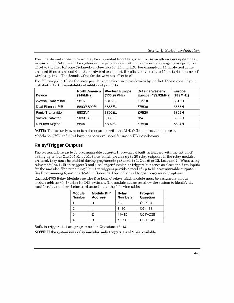
The 6 hardwired zones on board may be eliminated from the system to use an all-wireless system that supports up to 24 zones. The system can be programmed without skips in zone usage by assigning an offset to the first RF zone (Submode 2, Question 50, L1 and L2). For example, if 14 hardwired zones are used (6 on board and 8 on the hardwired expander), the offset may be set to 15 to start the usage of wireless points. The default value for the wireless offset is 07.
The following chart lists the most popular compatible wireless devices by market. Please consult your distributor for the availability of additional products.
Device North America (345MHz)
Western Europe (433.92MHz)
Outside Western Europe (433.92MHz)
Europe (868MHz)
2-Zone Transmitter 5816 5816EU ZR510 5816H
Dual Element PIR 5890/5890PI 5888EU ZR530 5888H
Panic Transmitter 5802MN 5802EU ZR520 5802H
Smoke Detector 5808LST 5808EU N/A 5808H
4-Button Keyfob 5804 5804EU ZR590 5804H
NOTE: This security system is not compatible with the ADEMCO bi–directional devices.
Models 5802MN and 5804 have not been evaluated for use in UL installations.
Relay/Trigger Outputs The system allows up to 22 programmable outputs. It provides 4 built-in triggers with the option of adding up to four XL4705 Relay Modules (which provide up to 20 relay outputs). If the relay modules are used, they must be enabled during programming (Submode 1, Question 12, Location 2). When using relay modules, built-in triggers 3 and 4 no longer function as triggers but serve as clock and data inputs for the modules. The remaining 2 built-in triggers provide a total of up to 22 programmable outputs. See Programming Questions 32–43 in Submode 1 for individual trigger programming options.
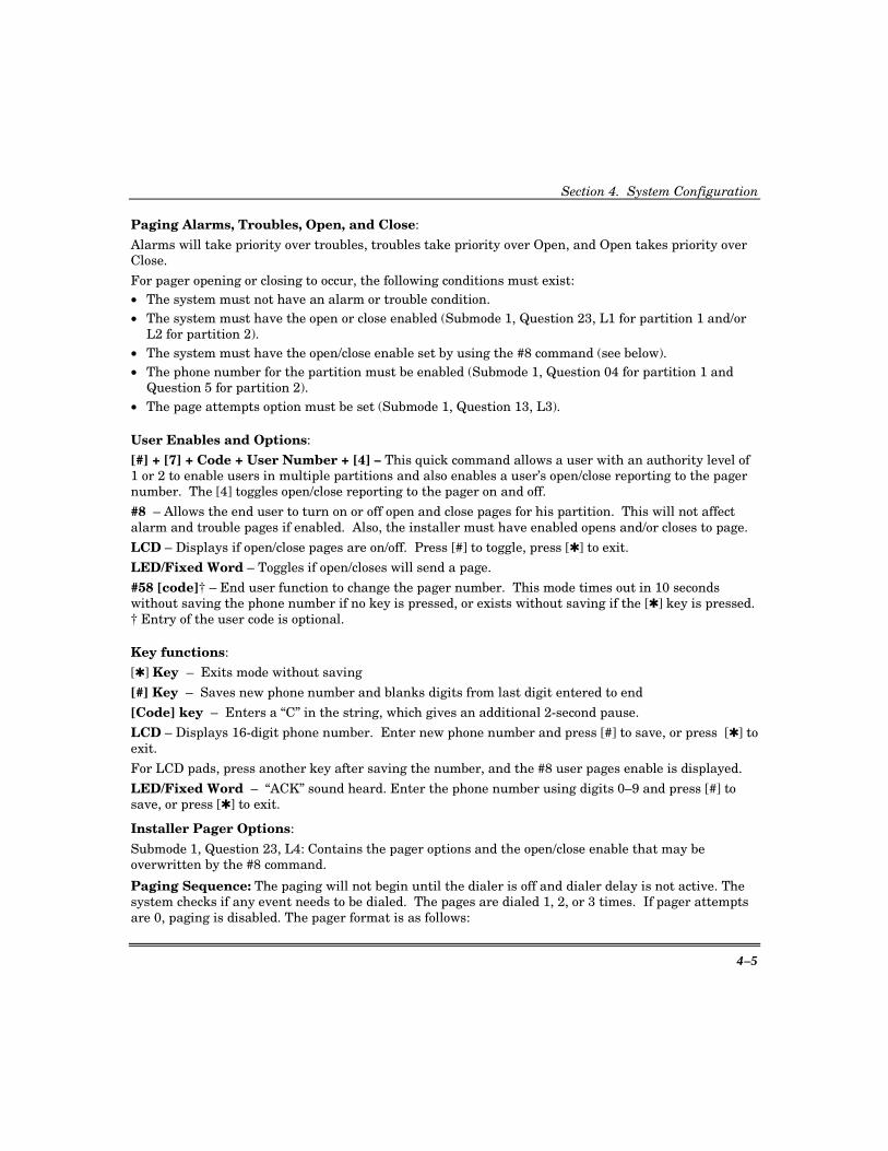
Each XL4705 Relay Module provides five form C relays. Each module must be assigned a unique module address (0–3) using its DIP switches. The module addresses allow the system to identify the specific relay numbers being used according to the following table:
Module Number
Module DIP Address
Relay Numbers
Program Question
1 0 1–5 Q32–34
2 1 6–10 Q34–36
3 2 11–15 Q37–Q39
4 3 16–20 Q39–Q41
Built-in triggers 1–4 are programmed in Questions 42–43.
NOTE: If the system uses relay modules, only triggers 1 and 2 are available.

OMNI624 Installation and Setup Guide
4–4
Connect the Relay Modules as shown:
1 2 3 4 5 6 7 8 9 10 11 12 13 14 15 16 17 18 19 20GND DATA CLK +12V NO NC C NO NC C NO NC C NO NC C NO NC C
Relay 1 Relay 2 Relay 3 Relay 4 Relay 5
XL4705 RELAYMODULE
CONNECTTO EARTHGROUND
TO AUX POWERTERMINALS
CONNECT TO TRIGGER 4
CONNECT TO TRIGGER 3
DATA
CLOCK
12V
REFER TO “DIP SWITCH ADDRESSING”
TABLE FOR SETTINGS
DIP SWITCHES
DIP SWITCH 1: In the ON position, inverts Relays 2 and 4, e.g., if wired for normally closed (N.C.), relay will change to normally open (N.O.), and vice versa.
SW1ON
OFF
1 2 3 4DIP SWITCHES
SHOWN IN “OFF” POSITION
Trigger Address Switch 2 Switch 3 Switch 4
1–5 OFF OFF OFF
6–10 ON OFF OFF
11–15 OFF ON OFF
16–20 ON ON OFF
DIP SWITCH ADDRESSING
* Modules may have to be powered from a separate12V power source if the total current drawn by the relay modules exceeds the current available from the control panel’s Auxiliary Power output.
SW1
USE TWISTEDPAIR FOR THESE WIRES
(4)
(7)
OMNI624-006-V0 XL4705 Current Advisory: Standby = 16mA
Each active relay = 40mA Total current drain with all five relays active = 200mA If a separate power supply is used to power the module, you must connect the power supply ground to the control panel ground terminal.
Paging Feature Summary: A 16-digit phone number to dial for paging by each partition (#58 user function), which the end user or installer can reprogram, is entered in Submode 1, Question 4 (partition 1) and Question 5 (partition 2). The number of times the pager number is dialed is installer-programmable from 1–3 times. The installer also selects which events may cause a page. Four conditions may be selected: (1) zone alarms, (2) 24-hour zone troubles, (3) openings, and (4) closings. The conditions are programmed in Submode 1, Question 23, Location 1 for partition 1 and Location 2 for partition 2. Each user code may also be enabled/disabled from sending pages on opens and closes. Additionally, paging may be turned on or off for opening and closing.
NOTE: Only one event is paged-based on the priority described next.
Section 4. System Configuration
4–5
Paging Alarms, Troubles, Open, and Close:
Alarms will take priority over troubles, troubles take priority over Open, and Open takes priority over Close.
For pager opening or closing to occur, the following conditions must exist: • The system must not have an alarm or trouble condition. • The system must have the open or close enabled (Submode 1, Question 23, L1 for partition 1 and/or
L2 for partition 2). • The system must have the open/close enable set by using the #8 command (see below). • The phone number for the partition must be enabled (Submode 1, Question 04 for partition 1 and
Question 5 for partition 2). • The page attempts option must be set (Submode 1, Question 13, L3).
User Enables and Options:
[#] + [7] + Code + User Number + [4] – This quick command allows a user with an authority level of 1 or 2 to enable users in multiple partitions and also enables a user’s open/close reporting to the pager number. The [4] toggles open/close reporting to the pager on and off.
#8 – Allows the end user to turn on or off open and close pages for his partition. This will not affect alarm and trouble pages if enabled. Also, the installer must have enabled opens and/or closes to page.
LCD – Displays if open/close pages are on/off. Press [#] to toggle, press [✱] to exit.
LED/Fixed Word – Toggles if open/closes will send a page.
#58 [code]† – End user function to change the pager number. This mode times out in 10 seconds without saving the phone number if no key is pressed, or exists without saving if the [✱] key is pressed. † Entry of the user code is optional.
Key functions:
[✱] Key – Exits mode without saving
[#] Key – Saves new phone number and blanks digits from last digit entered to end
[Code] key – Enters a “C” in the string, which gives an additional 2-second pause.
LCD – Displays 16-digit phone number. Enter new phone number and press [#] to save, or press [✱] to exit.
For LCD pads, press another key after saving the number, and the #8 user pages enable is displayed.
LED/Fixed Word – “ACK” sound heard. Enter the phone number using digits 0–9 and press [#] to save, or press [✱] to exit.
Installer Pager Options:
Submode 1, Question 23, L4: Contains the pager options and the open/close enable that may be overwritten by the #8 command.
Paging Sequence: The paging will not begin until the dialer is off and dialer delay is not active. The system checks if any event needs to be dialed. The pages are dialed 1, 2, or 3 times. If pager attempts are 0, paging is disabled. The pager format is as follows:

OMNI624 Installation and Setup Guide
4–6
Account Event Zone/User Terminator 1234 [0, 1, or 9] [000-255] [#]
where: Opening = 0 Closing = 1
Alarm or Trouble = 9 This data is transmitted 2 times with a 5-second pause between rounds.
5–1
S E C T I O N 5
System Operation • • • • • • • • • • • • • • • • • • • • • • • • • • • • • • • • • • • • • • • • • • •
Power Up/System Reset SYSTEM STABILIZATION MODE: Upon power-up of the system, if the system was previously armed, all the lights on the LED keypad(s) will turn ON momentarily or, in the case of an LCD display installation, the keypad(s) will display “PLEASE STAND BY POWER UP DELAY” HOWEVER, THE ZONES WILL NOT RESPOND TO ALARM CONDITIONS FOR APPROXIMATELY 2 MINUTES. The 2-minute interval is used to allow motion detectors (interior zones) to stabilize in order to prevent false alarms. This 2-minute delay can be disabled by shorting the yellow and black keypad wires (reduces the power-up reset time to approximately 5 seconds). Upon system power-up, if the system was previously disarmed, the power-up reset time will be approximately 5 seconds. If total system power is lost, upon power restoral the system will return to its previously armed state.
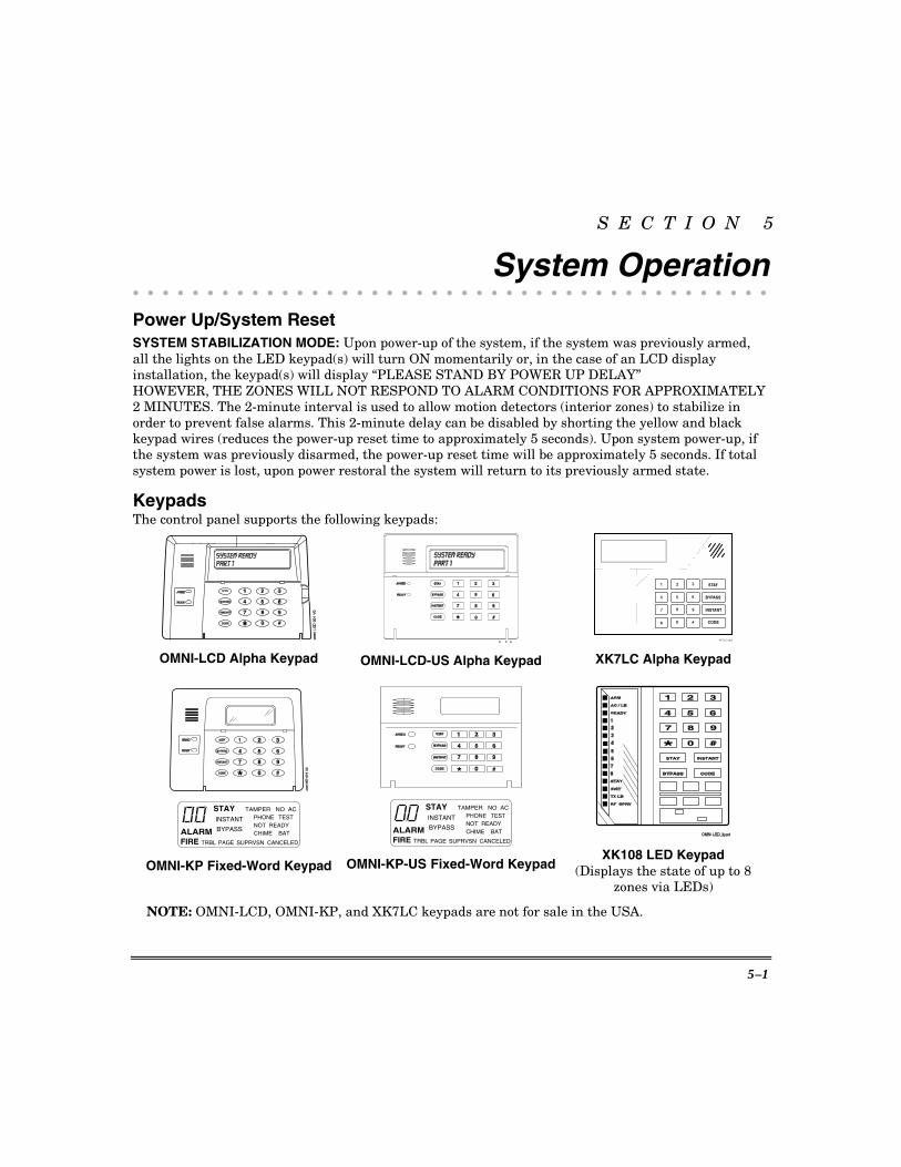
Keypads The control panel supports the following keypads:
OMNI-LCD Alpha Keypad
OMNI-LCD-US Alpha Keypad
STAY
BYPASS
INSTANT
CODE
1 2 3
4 5 6
7 8 9
* 0 #
XK-7LC_kypd XK7LC Alpha Keypad
ALARMFIRE
INSTANT
BYPASS
TRBL PAGE
STAY
SUPRVSN CANCELED
CHIME BATNOT READYPHONE TEST
TAMPER NO AC
OMNI-KP Fixed-Word Keypad
ALARMFIRE
INSTANT
BYPASS
TRBL PAGE
STAY
SUPRVSN CANCELED
CHIME BATNOT READYPHONE TEST
TAMPER NO AC
OMNI-KP-US Fixed-Word Keypad
XK108 LED Keypad (Displays the state of up to 8
zones via LEDs)
NOTE: OMNI-LCD, OMNI-KP, and XK7LC keypads are not for sale in the USA.
OMNI624 Installation and Setup Guide
5–2
1) ZONE STATUS LEDS (XK108) These LEDs display the current zone status including alarms, bypasses, and faults. Each condition will cause these LEDs to operate differently as follows:
ALARMS Fast Blink (approx. 150mS ON – 150mS OFF). TROUBLES Slow Pulse (approx. 600mS ON – 600mS OFF). BYPASSES Blink (100mS ON – 900mS OFF). Zone bypasses are displayed as a very slow blink of the zone LED light. FAULTED ZONES Solid ON. Faulted zones are the lowest-priority indication. Faulted burglary zones are displayed with the LED solidly ON while the system is disarmed. NORMAL OFF
Upon entry, the keypad sounder will annunciate to warn the user to disarm the system. In addition, the respective zone LED(s) will be ON to indicate zones which are violated (e.g., entry door and motion detector).
2) ARM/DISARM LED (ALL KEYPADS) This LED/display indicates that the system is currently armed (ON) or disarmed (OFF).
Fast Blink Alarm mode (alarms have occurred) Slow Blink Unable to communicate with central station
3) STAY LED This LED/display indicates that the system has been armed in the STAY, STAY/INSTANT, or AUTO/STAY mode. STAY/INSTANT is enabled in programming Question 14, Location 1. The STAY LED indicates the following:
ON Stay/AutoStay zones are bypassed OFF Stay/AutoStay zones are normal
4) INSTANT LED This LED/display indicates that the system has been armed in the INSTANT or STAY/INSTANT mode, meaning that the system is currently armed, all delay zones are instant (no delay time). See programming Question 14, Location 1.
ON Delay zones are currently instant OFF Delay zones are normal
5) AC/LOW BATTERY LED This LED/display indicates the current power status of the panel as follows:
ON AC is present OFF No AC, running on battery backup Slow Blink Low-battery condition detected
6) READY LED This LED/display indicates that the system is ready for arming. The READY LED is common to all BURGLARY ZONES with the following indications:
ON System ready to be armed OFF System not ready to be armed

Section 5. System Operation
5–3
Slow Blink Indicates Installer programming mode Fast Blink Alarm Memory mode
7) SUPER LED This LED/display indicates the status of supervised devices as follows:
Slow Blink Bell supervision Fast Blink Zone tamper
8) [STAY] BUTTON The [STAY] button arms the system, excluding zones programmed as Stay/AutoStay zones. This provides exterior protection of the premises while allowing full access throughout the interior.
9) [BYPASS] BUTTON The [BYPASS] button is used to temporarily exclude protection to a specific zone(s).
10) [INSTANT] BUTTON If pressed, the [INSTANT] button allows arming the system in the INSTANT mode; with the [STAY] button, it enables arming the system in the STAY/INSTANT mode. NOTE: INSTANT mode is enabled in Question 14, Location 1.
11) [CODE] BUTTON The [CODE] button is used to allow entry into the Installer programming mode and permits the entry of user codes.
12) KEYPAD AUXILIARY KEYS Pressing the auxiliary keys (XK108: two keys labeled P, A, or F at the same time; OMNI-LCD/ OMNI-LCD-US/XK7LC/OMNI-KP/OMNI-KP-US: 1/3, 7/9, ✱/#) initiates a CS transmission, if programmed, of programmed functions (e.g., PANIC, AUXILIARY, or FIRE), and causes annunciation of the keypad sounder and turns on the bell output. The programmed functions are defined in Programming Submode 1, Questions 26 and 27.
See “Keypad Emergency Conditions” in this section for alternate auxiliary keys.
Keypad Sounder The sounder (or loudspeaker) housed inside the keypad emits (annunciates) sounds according to the condition of the security system.
Enabling keypad sounder: XK7LC: Set the 4th DIP switch on the back of the keypad (remove cover) on or off to turn sounder on/off. OMNI-KP and OMNI-KP-US: Press the BYPASS and CODE keys at the same time and hold down for two seconds until you hear a beep. Press any key (except the [✱] key) to toggle the sounder on or off.
0 = Sounder off 1 = Sounder on
Press the [✱] key to exit the sounder menu.
OMNI624 Installation and Setup Guide
5–4
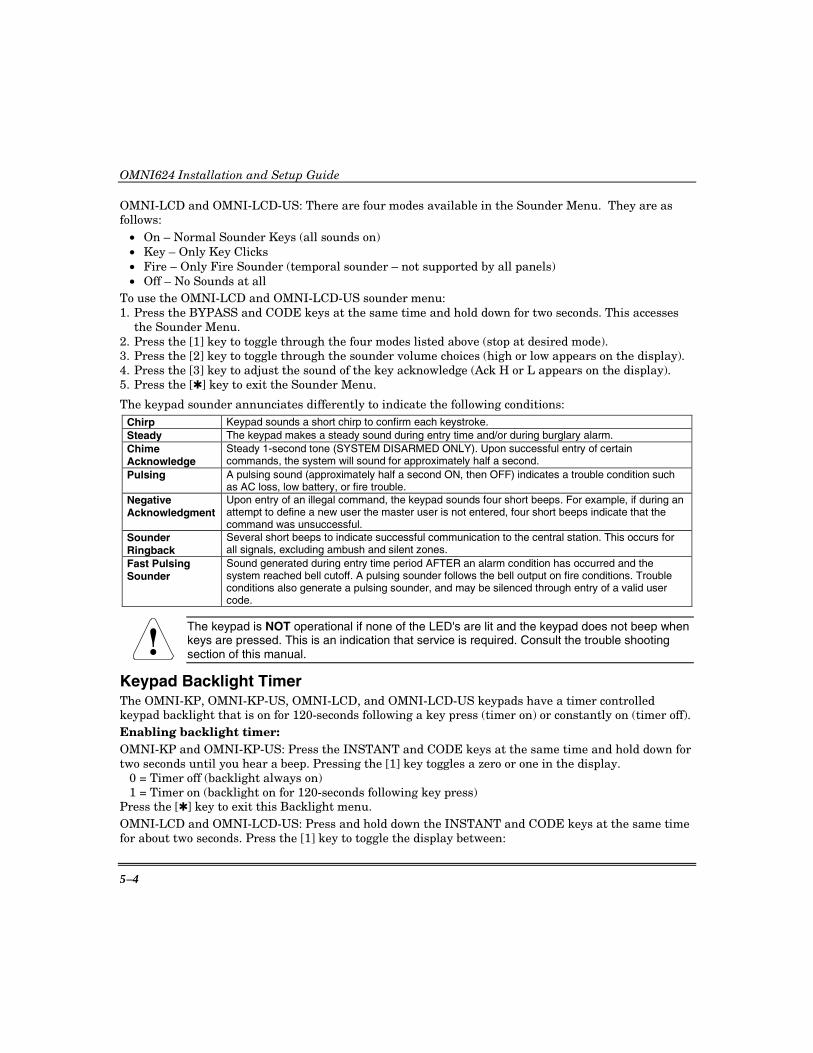
OMNI-LCD and OMNI-LCD-US: There are four modes available in the Sounder Menu. They are as follows:
• On – Normal Sounder Keys (all sounds on) • Key – Only Key Clicks • Fire – Only Fire Sounder (temporal sounder – not supported by all panels) • Off – No Sounds at all
To use the OMNI-LCD and OMNI-LCD-US sounder menu: 1. Press the BYPASS and CODE keys at the same time and hold down for two seconds. This accesses
the Sounder Menu. 2. Press the [1] key to toggle through the four modes listed above (stop at desired mode). 3. Press the [2] key to toggle through the sounder volume choices (high or low appears on the display). 4. Press the [3] key to adjust the sound of the key acknowledge (Ack H or L appears on the display). 5. Press the [✱] key to exit the Sounder Menu.
The keypad sounder annunciates differently to indicate the following conditions: Chirp Keypad sounds a short chirp to confirm each keystroke. Steady The keypad makes a steady sound during entry time and/or during burglary alarm. Chime Acknowledge
Steady 1-second tone (SYSTEM DISARMED ONLY). Upon successful entry of certain commands, the system will sound for approximately half a second.
Pulsing A pulsing sound (approximately half a second ON, then OFF) indicates a trouble condition such as AC loss, low battery, or fire trouble.
Negative Acknowledgment
Upon entry of an illegal command, the keypad sounds four short beeps. For example, if during an attempt to define a new user the master user is not entered, four short beeps indicate that the command was unsuccessful.
Sounder Ringback
Several short beeps to indicate successful communication to the central station. This occurs for all signals, excluding ambush and silent zones.
Fast Pulsing Sounder
Sound generated during entry time period AFTER an alarm condition has occurred and the system reached bell cutoff. A pulsing sounder follows the bell output on fire conditions. Trouble conditions also generate a pulsing sounder, and may be silenced through entry of a valid user code.
!
The keypad is NOT operational if none of the LED's are lit and the keypad does not beep when keys are pressed. This is an indication that service is required. Consult the trouble shooting section of this manual.
Keypad Backlight Timer The OMNI-KP, OMNI-KP-US, OMNI-LCD, and OMNI-LCD-US keypads have a timer controlled keypad backlight that is on for 120-seconds following a key press (timer on) or constantly on (timer off). Enabling backlight timer: OMNI-KP and OMNI-KP-US: Press the INSTANT and CODE keys at the same time and hold down for two seconds until you hear a beep. Pressing the [1] key toggles a zero or one in the display.
0 = Timer off (backlight always on) 1 = Timer on (backlight on for 120-seconds following key press)
Press the [✱] key to exit this Backlight menu. OMNI-LCD and OMNI-LCD-US: Press and hold down the INSTANT and CODE keys at the same time for about two seconds. Press the [1] key to toggle the display between:

Section 5. System Operation
5–5
Backlight 120s time out and
Backlight Always On Press [✱] key to exit this Backlight menu.
Keypad Addressing This address will identify the keypad number to the control panel. A maximum of 12 keypads (OMNI-KP, OMNI-KP-US, OMNI-LCD, OMNI-LCD-US, or XK7LC,) can be identified, but the total of 12 cannot be comprised of more than 8 LCD keypads or a combination of 8 LED/fixed-word keypads. NOTE: The XK108 keypad may also be used on the system; however, when using the XK108, keypad addressing does not apply. Additionally, you can not use any other type of keypad if using XK108’s on the system. Set the OMNI-KP, OMNI-KP-US, OMNI-LCD, and OMNI-LCD-US keypad addresses by doing the following (refer to the instructions provided with the keypads for additional information on setting the keypad addresses): 1. Within 30 seconds of applying power to the unit, press the [CODE] and [STAY] keys at the same
time and hold them for several seconds. 2. When the display shows a single digit pulsing, enter the address 1–8 for fixed-word and for LCD
keypads. 3. To terminate the mode, press [✱].
Switch Address
1 2 3 01 ON ON ON 02 off ON ON 03 ON off ON 04 off off ON 05 ON ON off 06 off ON off 07 ON off off
Set the XK7LC keypad address by using its DIP switches.
Refer to the instructions provided with the keypad for additional information on setting the keypad address.
08 off off off
Arming the System The system can be armed only if all burglary zones are in ready state (not faulted):
LCD Keypad Fixed-Word Keypad LED Keypad Indicator LED Lit Ready Ready Ready Display SYSTEM READY N/A N/A
TO ARM: Enter any programmed four-digit user code. NOTE: The factory default for user #1 is 1234. The ARMED LED will light and the user may pass through interior zones (if necessary) and exit through an exit/entry zone for the time period programmed as the exit delay. LCD display keypads provide the following indications:
LCD Keypad Fixed-Word Keypad LED Keypad Indicator LED Lit Armed Armed Armed Display ON: AWAY; EXIT NOW AWAY N/A

OMNI624 Installation and Setup Guide
5–6
The system can be armed without the backup battery being connected; however, the AC/LB or BAT light will flash depending on the keypad used.
Arm While Faulted: If programmed (Submode 1, Question 14, Location 2), the user can arm the system while a delay or interior zone is still faulted.
AUTO STAY ARMING TO ARM: Enter any programmed four-digit user code. If the user does not access an exit/entry zone during the exit time and auto stay zones are programmed, the panel arms Auto Stay and bypasses any zones programmed to do so.
LCD Keypad Fixed-Word Keypad LED Keypad
Indicator LED Lit Armed Armed Armed, Stay
Display ON:AUTO STAY STAY N/A
NOTE: The system will not Auto Stay arm if an Instant zone is faulted when the user code is entered.
STAY ARMING TO ARM: Press the [STAY] key followed by a four-digit user code. This will arm the system with all programmed interior zones bypassed.
LCD Keypad Fixed-Word Keypad LED Keypad
Indicator LED Lit Armed Armed Armed, Stay
Display ON: STAY STAY N/A
INSTANT ARMING TO ARM: Press the [INSTANT] key followed by a four-digit user code. The INSTANT and ARM LEDs will light continuously.
LCD Keypad Fixed-Word Keypad LED Keypad
Indicator LED Lit Armed Armed Armed, Instant
Display ON: INSTANT INSTANT N/A
The entire security system (interior and exterior) is armed at this time, eliminating the entry time delay(s) that have been programmed into the system. NOTE: The Instant mode can be enabled through programming Submode 1, Question 14, Location 1.
STAY/INSTANT ARMING
TO ARM: Press the [STAY] key; press the [INSTANT] key and enter a four-digit user code. The STAY/INSTANT mode will arm the system with the characteristics of both the STAY and INSTANT modes. The keypads will have the ARM, INSTANT and STAY LEDs turned ON continuously.
LCD Keypad Fixed-Word Keypad LED Keypad Indicator LED Lit Armed Armed Armed, Instant, Stay Display ON: STAY/INS STAY
INSTANT N/A
The system will be armed with the interior zones bypassed and the delay zones instant. NOTE: The STAY/INSTANT mode can be enabled through programming Question 14, Location 1.
Section 5. System Operation
5–7
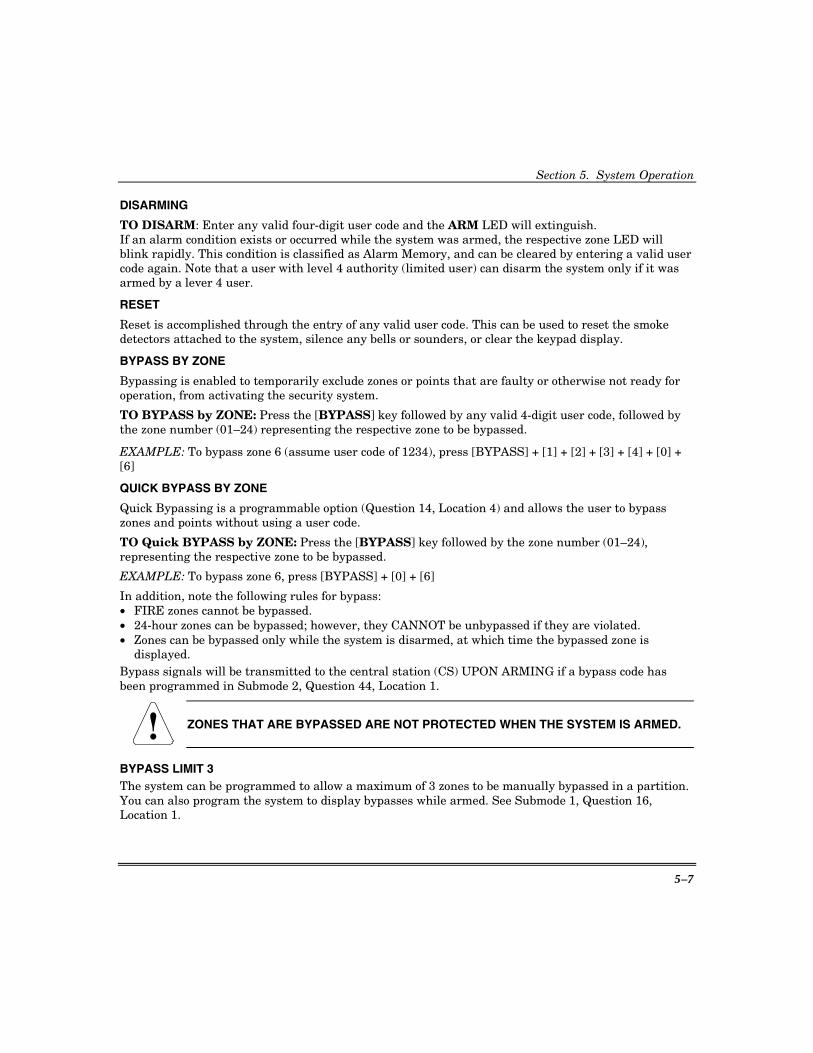
DISARMING
TO DISARM: Enter any valid four-digit user code and the ARM LED will extinguish. If an alarm condition exists or occurred while the system was armed, the respective zone LED will blink rapidly. This condition is classified as Alarm Memory, and can be cleared by entering a valid user code again. Note that a user with level 4 authority (limited user) can disarm the system only if it was armed by a lever 4 user.
RESET
Reset is accomplished through the entry of any valid user code. This can be used to reset the smoke detectors attached to the system, silence any bells or sounders, or clear the keypad display.
BYPASS BY ZONE
Bypassing is enabled to temporarily exclude zones or points that are faulty or otherwise not ready for operation, from activating the security system.
TO BYPASS by ZONE: Press the [BYPASS] key followed by any valid 4-digit user code, followed by the zone number (01–24) representing the respective zone to be bypassed.
EXAMPLE: To bypass zone 6 (assume user code of 1234), press [BYPASS] + [1] + [2] + [3] + [4] + [0] + [6]
QUICK BYPASS BY ZONE
Quick Bypassing is a programmable option (Question 14, Location 4) and allows the user to bypass zones and points without using a user code.
TO Quick BYPASS by ZONE: Press the [BYPASS] key followed by the zone number (01–24), representing the respective zone to be bypassed.
EXAMPLE: To bypass zone 6, press [BYPASS] + [0] + [6]
In addition, note the following rules for bypass: • FIRE zones cannot be bypassed. • 24-hour zones can be bypassed; however, they CANNOT be unbypassed if they are violated. • Zones can be bypassed only while the system is disarmed, at which time the bypassed zone is
displayed. Bypass signals will be transmitted to the central station (CS) UPON ARMING if a bypass code has been programmed in Submode 2, Question 44, Location 1.
!
ZONES THAT ARE BYPASSED ARE NOT PROTECTED WHEN THE SYSTEM IS ARMED.
BYPASS LIMIT 3 The system can be programmed to allow a maximum of 3 zones to be manually bypassed in a partition. You can also program the system to display bypasses while armed. See Submode 1, Question 16, Location 1.
OMNI624 Installation and Setup Guide
5–8
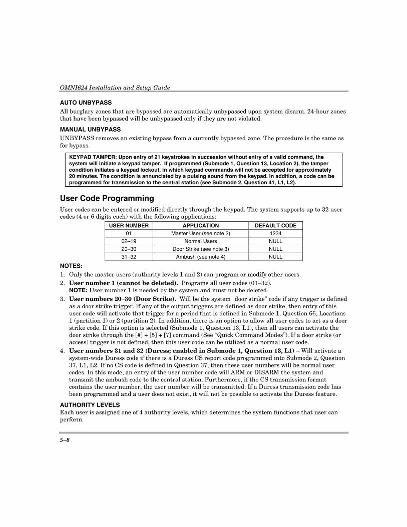
AUTO UNBYPASS All burglary zones that are bypassed are automatically unbypassed upon system disarm. 24-hour zones that have been bypassed will be unbypassed only if they are not violated.
MANUAL UNBYPASS UNBYPASS removes an existing bypass from a currently bypassed zone. The procedure is the same as for bypass.
KEYPAD TAMPER: Upon entry of 21 keystrokes in succession without entry of a valid command, the system will initiate a keypad tamper. If programmed (Submode 1, Question 13, Location 2), the tamper condition initiates a keypad lockout, in which keypad commands will not be accepted for approximately 20 minutes. The condition is annunciated by a pulsing sound from the keypad. In addition, a code can be programmed for transmission to the central station (see Submode 2, Question 41, L1, L2).
User Code Programming User codes can be entered or modified directly through the keypad. The system supports up to 32 user codes (4 or 6 digits each) with the following applications:
USER NUMBER APPLICATION DEFAULT CODE 01 Master User (see note 2) 1234
02–19 Normal Users NULL
20–30 Door Strike (see note 3) NULL
31–32 Ambush (see note 4) NULL
NOTES: 1. Only the master users (authority levels 1 and 2) can program or modify other users. 2. User number 1 (cannot be deleted). Programs all user codes (01–32).
NOTE: User number 1 is needed by the system and must not be deleted. 3. User numbers 20–30 (Door Strike). Will be the system "door strike" code if any trigger is defined
as a door strike trigger. If any of the output triggers are defined as door strike, then entry of this user code will activate that trigger for a period that is defined in Submode 1, Question 66, Locations 1 (partition 1) or 2 (partition 2). In addition, there is an option to allow all user codes to act as a door strike code. If this option is selected (Submode 1, Question 13, L1), then all users can activate the door strike through the [#] + [5] + [7] command (See “Quick Command Modes”). If a door strike (or access) trigger is not defined, then this user code can be utilized as a normal user code.
4. User numbers 31 and 32 (Duress; enabled in Submode 1, Question 13, L1) – Will activate a system-wide Duress code if there is a Duress CS report code programmed into Submode 2, Question 37, L1, L2. If no CS code is defined in Question 37, then these user numbers will be normal user codes. In this mode, an entry of the user number code will ARM or DISARM the system and transmit the ambush code to the central station. Furthermore, if the CS transmission format contains the user number, the user number will be transmitted. If a Duress transmission code has been programmed and a user does not exist, it will not be possible to activate the Duress feature.
AUTHORITY LEVELS Each user is assigned one of 4 authority levels, which determines the system functions that user can perform.
Section 5. System Operation
5–9
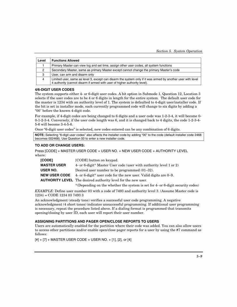
Level Functions Allowed
1 Primary Master can view log and set time, assign other user codes, all system functions
2 Secondary Master, same as primary Master except cannot change the primary Master’s code
3 User, can arm and disarm only
4 Limited user, same as level 3, except can disarm the system only if it was armed by another user with level 4 authority (cannot disarm if armed with user of higher authority level).
4/6-DIGIT USER CODES The system supports either 4- or 6-digit user codes. A bit option in Submode 1, Question 12, Location 3 selects if the user codes are to be 4 or 6 digits in length for the entire system. The default user code for the master is 1234 with an authority level of 1. The system is defaulted to 4-digit user/installer code. If the bit is set in installer mode, each currently programmed code will change to six digits by adding a “00" before the known 4-digit code.
For example, if 4-digit codes are being changed to 6 digits and a user code was 1-2-3-4, it will become 0-0-1-2-3-4. Conversely, if the user code length was 6, and it is changed back to 4 digits, the code 1-2-3-4-5-6 will become 3-4-5-6. Once “6-digit user codes” is selected, new codes entered can be any combination of 6 digits.
NOTE: Selecting “6-digit user codes” also affects the installer code by adding “00” to the code (default installer code 2468 becomes 002468). Use Question 00 to enter a new installer code.
TO ADD OR CHANGE USERS:
Press [CODE] + MASTER USER CODE + USER NO. + NEW USER CODE + AUTHORITY LEVEL where:
[CODE] [CODE] button on keypad. MASTER USER 4- or 6-digit* Master User code (user with authority level 1 or 2) USER NO. Desired user number to be programmed (01–32). NEW USER CODE 4- or 6-digit* user code for the new user. Valid digits are 0–9. AUTHORITY LEVEL The desired authority level for the new user.
*(Depending on the whether the system is set for 4- or 6-digit security codes)
EXAMPLE: Define user number 03 with a code of 7493 and authority level 3. (Assume Master code is 1234) = CODE 1234 03 7493 3 An acknowledgment (steady tone) verifies a successful user code programming. A negative acknowledgment (4 short tones) indicates unsuccessful programming. If additional user programming is necessary, repeat the procedure listed above. If a dialing format is programmed that transmits opening/closing by user ID, each user will report their user number.
ASSIGNING PARTITIONS AND PAGER OPEN/CLOSE REPORTS TO USERS Users are automatically enabled for the partition where their code was added. You can also allow users to access other partitions and/or enable open/close pager reports for a user by using the #7 command as follows:
[#] + [7] + MASTER USER CODE + USER NO. + [1], [2], or [4]

OMNI624 Installation and Setup Guide
5–10
where: MASTER USER User with authority level 1 or 2. USER NO. The user that will be assigned access to other partitions. 1, 2, or 4 Select 1 or 2 to assign access to a partition to that user. Select 4 to enable open/close paging report for that user.
To exit this mode, press [✱].
User code programming can ONLY be performed while the system is DISARMED.
User Deletion User codes (02–32) can be deleted from any keypad. Once deleted, their values are null.
TO DELETE USERS: [CODE] + MASTER CODE + USER NO. + [#]
where:
[CODE] [CODE] button on keypad.
MASTER CODE Master User code.
USER NO. Desired user number being deleted (02–32).
[#] [#] button.
Keypad Emergency Conditions The system is capable of transmitting four keypad auxiliary conditions as follows:
CONDITION KEYSTROKES CS REPORT ENABLE OPTIONS (aud./silent; arm beeps; relays)
PANIC # & ✱ (at the same time)
Submode 2, Question 38, L1, L2
See Submode 1, Question 27, L1, L2 Immediate and unabortable.
FIRE 7 & 9 (at the same time)
Submode 2, Question 40, L1, L2
See Submode 1, Question 26, L3, L4
AUXILIARY 1 & 3 (at the same time)
Submode 2, Question 40, L3, L4
See Submode 1, Question 26, L1, L2
DURESS User code #31 and 32
Submode 2, Question 37, L1, L2
See Submode 1, Question 13, L1
The keypads have additional keys dedicated for emergency conditions. These can be activated by pressing both keys at the same time (see “Keypads” in this section).
Audible Panic, Fire, and Audible Auxiliary can be RESET BY ENTERING ANY VALID USER CODE.
Section 5. System Operation
5–11
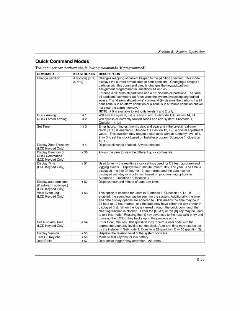
Quick Command Modes The end user can perform the following commands (if programmed):
COMMAND KEYSTROKES DESCRIPTION Change partition # 0 [code] [0, 1,
2, or 9] Changes mapping of current keypad to the partition specified. This mode displays the current armed state of both partitions. Changing a keypad’s partition with this command directly changes the keypad/partition assignment programmed in Questions 44 and 45. Entering a “0” arms all partitions and a “9” disarms all partitions. The “arm all partitions” command (0) force arms the system bypassing any faulted zones. The “disarm all partitions” command (9) disarms the partions if a 24 hour zone is in an alarm condition or a zone is in a trouble condition but will not clear the alarm memory. NOTE: # 0 is available to authority levels 1 and 2 only.
Quick Arming # 1 Will arm the system, if it is ready to arm. Submode 1, Question 14, L4 Quick Forced Arming # 2 Will bypass all currently faulted zones and arm system. Submode 1,
Question 14, L4 Set Time # 3 Enter hours, minutes, month, day, and year and if the crystal real-time
clock (RTC) is enabled (Submode 1, Question 13, L2), a crystal adjustment value. This question may require a user code with an authority level of 1, 2, or 3 to set the clock based on Installer program (Submode 1, Question 16, L2).
Display Zone Directory (LCD Keypad Only)
# 4 Displays all zones enabled. Always enabled.
Display Directory of Quick Commands (LCD Keypad Only)
# 50 Allows the user to view the different quick commands.
Display Time (LCD Keypad Only)
# 51 Used to verify the real-time clock settings used for CS test, auto-arm and logging events. Displays hour, minute, month, day, and year. The time is displayed in either 24 hour or 12 hour format and the date may be displayed with day or month first, based on programming options in Submode 1, Question 16, location 3.
Display auto-arm time (if auto-arm optioned ) (LCD Keypad Only)
# 52 Displays hour and minute of auto-arm time.
View Event Log (LCD Keypad Only)
# 53 This option is enabled for users in Submode 1, Question 17, L1. If enabled, the event log may be seen for the system. Additionally, the time and date display options are adhered to. This means the time may be in 24 hour or 12 hour format, and the date may have either the day or month displayed first. When the log is viewed through the quick command, the clear log function is blocked. Either the [STAY] or the [✱] key may be used to exit this mode. Pressing the [#] key advances to the next valid entry and pressing the [CODE] key backs up to the previous entry.
Set Auto-arm Time (LCD Keypad Only)
# 54 Enter Hour, Minutes. This question may require a user code with the appropriate authority level to set the clock. Auto-arm time may also be set by the installer in Submode 1, Questions 29 (partition 1) or 30 (partition 2).
Display Version # 55 Displays the revision level of the system software. Test RF Keyfobs # 56 Mode to test keyfobs for low battery. Door Strike # 57 Door strike trigger/relay activation. All Users.

OMNI624 Installation and Setup Guide
5–12
COMMAND KEYSTROKES DESCRIPTION Change pager number # 58 Lets the user modify the current pager phone number.
Note: Once the number is changed, pager reports will go to that number until the number is changed again using the #58 command.
Display/Toggle Chime #6 The LCD keypad will display current state and provide option to toggle the current state. The LED pads will simply toggle the chime state and beep once to indicate the state has changed.
Multi-partition assignment
#7 [Code] [user no.] [1, 2, or 4]
(4 = enable paging)
Allows the assignment of user codes to multiple partitions. User with authority of 1 or 2 is required to enter this mode. This allows users to be enabled in both partitions (1 and 2) and also enables the user for paging (4).
Pager enable #8 Toggle state of pager. Works same as chime. For user open/close only. User On-line Download #9 Starts remote connect sequence with PC downloader.
Quick commands are valid for 10 seconds of no activity, unless otherwise stated.
CHANGE PARTITION: [#] [0] [#] [0] [CODE] [0], [1], [2], or [9] OMNI-KP and OMNI-KP-US keypads display “EC” (enter code) after pressing #0, then display “CP” (change partition) after entering the user code. NOTE: #0 is available to authority level 1 and 2 users only.
QUICK ARMING: # 1 If programmed, Quick Arming will be permitted. Quick Arming allows arming the system without entry of a user code, and reports as user F or 128 if CID reporting is being used. Quick Arming has not been evaluated by UL. NOTE: The system must be in Ready mode. A user code is required to disarm the system. Options include:
[STAY] [#] [1] Quick Arm the System in the STAY mode [INSTANT] [#] [1] Quick Arm the System in the INSTANT mode [STAY][INSTANT] [#] [1] Quick Arm the System in the STAY/INSTANT mode
QUICK FORCED ARMING: # 2 If programmed, then Quick Forced Arming will be permitted. Quick Forced Arming allows arming the system without entry of a user code, and bypasses any bypassable zones that are not ready. It reports as user F or 127 if CID reporting is being used. Quick Forced Arming has not been evaluated by UL. NOTE: Bypassed zones will include all of the individual points assigned to the zone. A user code is required to disarm.
SET TIME: # 3 Pressing [#] [3] sets the time of the system clock. If a user code is required to set the time, then enter:
[#] + [3] + USER NO. + HOUR + MINUTE + MONTH + DAY + YEAR + CRYSTAL ADJUST (optional) + ADJUST VALUE (optional)
where: USER NO. = a valid 4-digit user code HOUR = two-digit hour of day in military time; e.g., 7AM = 07; 3PM = 15 MINUTE = two-digit minutes of hour; e.g., 9 min = 09; 29 min. = 29
Section 5. System Operation
5–13
MONTH = two-digit month of year (01 - 12); e.g., Feb = 02; Oct = 10 DAY = two-digit day of month (01-31) YEAR = two-digit year 00-99; e.g., 1998 = 98; 2000 = 00 CRYSTAL ADJUST = One-digit entry that is requested if using the Crystal RTC (enabled in Submode
1, Question 13, Location 2). If the clock is keeping the correct time, enter 1 followed by 00 for the adjust value. If the clock is not keeping the correct time, enter 1 (Adjust up - Clock slow) or 2 (Adjust down - Clock fast). For example, if the clock is showing 5:02 and the actual time is 5:00, enter 2.
ADJUST VALUE = The number of seconds to be added to or subtracted from the RTC on a daily basis. Note that the system only displays this prompt if the Crystal RTC has been enabled (Submode 1, Question 13, Location 2). Valid entries are 00 for no change, 1–29 for seconds to add (per day), or 1–29 for seconds to subtract (per day). To calculate the amount of change: 1. Determine how far off the clock is (in seconds) from the correct time. For
example, under Crystal Adjust above, the example was that the clock was showing 5:02 and the actual time was 5:00. Therefore, the clock is 2 minutes or 120 seconds (2 X 60 = 120) fast.
2. Determine the number of days since the last time the clock was set. For example, assume that it is now May 1 and the clock was last set on April 1. Therefore, it has been 30 days since the last time the clock was set.
3. Divide the number of seconds that the clock is off by the number of days since the last time the clock was set. For example, in the steps above we found that the clock was off by 120 seconds and the number of days since it was last set was 30. Therefore, 120 divided by 30 is 4 seconds as the Adjust Value.
4. Enter the result of step 3 as the adjust value. If the value entered is valid, an acknowledgement is sounded. If the value entered is not within the valid range, an error is sounded.
If a user code is not required to set the time, then enter: [#] + [3] + HOUR + MINUTE + MONTH + DAY + YEAR+ CRYSTAL ADJUST (optional)
ADJUSTMENT VALUE (optional) In either case, the LCD keypads display a prompt for each entry. On LED keypads, the sounder beeps after each entry. The system exits this mode either automatically (no keys are pressed), after the last entry (YEAR), or after the [✱] key is pressed. NOTE: The system time clock is used for the system test transmission as well as the auto arming function and log.
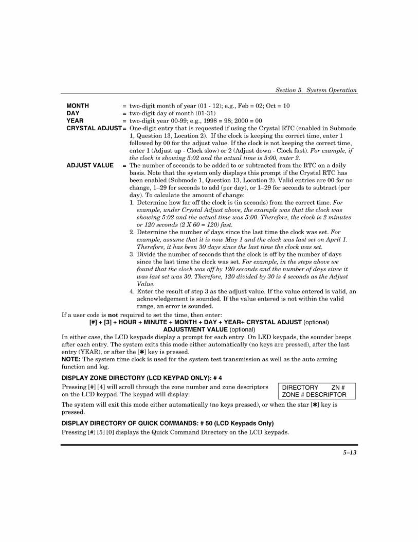
DISPLAY ZONE DIRECTORY (LCD KEYPAD ONLY): # 4 Pressing [#] [4] will scroll through the zone number and zone descriptors on the LCD keypad. The keypad will display:
DIRECTORY ZN # ZONE # DESCRIPTOR
The system will exit this mode either automatically (no keys pressed), or when the star [✱] key is pressed.
DISPLAY DIRECTORY OF QUICK COMMANDS: # 50 (LCD Keypads Only) Pressing [#] [5] [0] displays the Quick Command Directory on the LCD keypads.
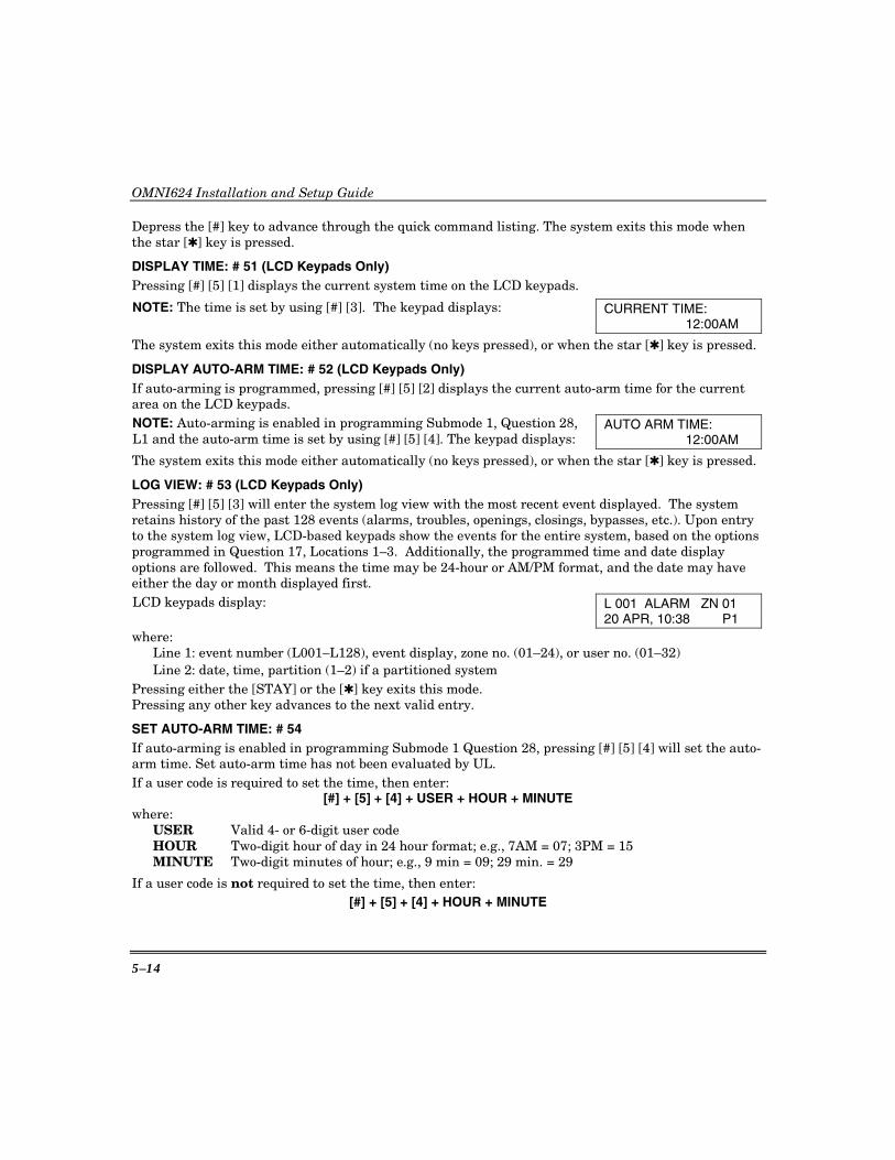
OMNI624 Installation and Setup Guide
5–14
Depress the [#] key to advance through the quick command listing. The system exits this mode when the star [✱] key is pressed.
DISPLAY TIME: # 51 (LCD Keypads Only) Pressing [#] [5] [1] displays the current system time on the LCD keypads.
NOTE: The time is set by using [#] [3]. The keypad displays: CURRENT TIME: 12:00AM
The system exits this mode either automatically (no keys pressed), or when the star [✱] key is pressed.
DISPLAY AUTO-ARM TIME: # 52 (LCD Keypads Only) If auto-arming is programmed, pressing [#] [5] [2] displays the current auto-arm time for the current area on the LCD keypads. NOTE: Auto-arming is enabled in programming Submode 1, Question 28, L1 and the auto-arm time is set by using [#] [5] [4]. The keypad displays:
AUTO ARM TIME: 12:00AM
The system exits this mode either automatically (no keys pressed), or when the star [✱] key is pressed.
LOG VIEW: # 53 (LCD Keypads Only) Pressing [#] [5] [3] will enter the system log view with the most recent event displayed. The system retains history of the past 128 events (alarms, troubles, openings, closings, bypasses, etc.). Upon entry to the system log view, LCD-based keypads show the events for the entire system, based on the options programmed in Question 17, Locations 1–3. Additionally, the programmed time and date display options are followed. This means the time may be 24-hour or AM/PM format, and the date may have either the day or month displayed first. LCD keypads display: L 001 ALARM ZN 01
20 APR, 10:38 P1 where:
Line 1: event number (L001–L128), event display, zone no. (01–24), or user no. (01–32) Line 2: date, time, partition (1–2) if a partitioned system
Pressing either the [STAY] or the [✱] key exits this mode. Pressing any other key advances to the next valid entry.
SET AUTO-ARM TIME: # 54 If auto-arming is enabled in programming Submode 1 Question 28, pressing [#] [5] [4] will set the auto-arm time. Set auto-arm time has not been evaluated by UL. If a user code is required to set the time, then enter:
[#] + [5] + [4] + USER + HOUR + MINUTE where:
USER Valid 4- or 6-digit user code HOUR Two-digit hour of day in 24 hour format; e.g., 7AM = 07; 3PM = 15 MINUTE Two-digit minutes of hour; e.g., 9 min = 09; 29 min. = 29
If a user code is not required to set the time, then enter: [#] + [5] + [4] + HOUR + MINUTE
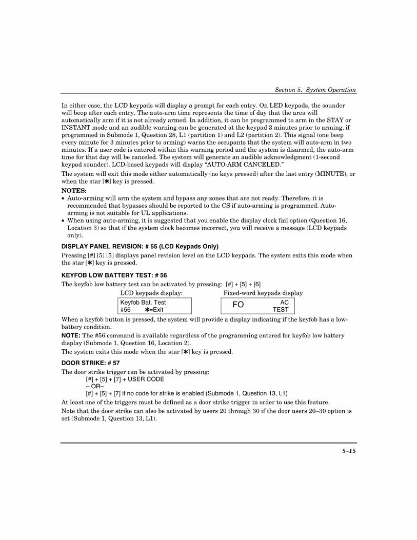
Section 5. System Operation
5–15
In either case, the LCD keypads will display a prompt for each entry. On LED keypads, the sounder will beep after each entry. The auto-arm time represents the time of day that the area will automatically arm if it is not already armed. In addition, it can be programmed to arm in the STAY or INSTANT mode and an audible warning can be generated at the keypad 3 minutes prior to arming, if programmed in Submode 1, Question 28, L1 (partition 1) and L2 (partition 2). This signal (one beep every minute for 3 minutes prior to arming) warns the occupants that the system will auto-arm in two minutes. If a user code is entered within this warning period and the system is disarmed, the auto-arm time for that day will be canceled. The system will generate an audible acknowledgment (1-second keypad sounder). LCD-based keypads will display “AUTO-ARM CANCELED.”
The system will exit this mode either automatically (no keys pressed) after the last entry (MINUTE), or when the star [✱] key is pressed.
NOTES: • Auto-arming will arm the system and bypass any zones that are not ready. Therefore, it is
recommended that bypasses should be reported to the CS if auto-arming is programmed. Auto-arming is not suitable for UL applications.
• When using auto-arming, it is suggested that you enable the display clock fail option (Question 16, Location 3) so that if the system clock becomes incorrect, you will receive a message (LCD keypads only).
DISPLAY PANEL REVISION: # 55 (LCD Keypads Only) Pressing [#] [5] [5] displays panel revision level on the LCD keypads. The system exits this mode when the star [✱] key is pressed.
KEYFOB LOW BATTERY TEST: # 56 The keyfob low battery test can be activated by pressing: [#] + [5] + [6]
LCD keypads display: Fixed-word keypads display
Keyfob Bat. Test #56 ✱=Exit
FO AC TEST
When a keyfob button is pressed, the system will provide a display indicating if the keyfob has a low-battery condition. NOTE: The #56 command is available regardless of the programming entered for keyfob low battery display (Submode 1, Question 16, Location 2). The system exits this mode when the star [✱] key is pressed.
DOOR STRIKE: # 57 The door strike trigger can be activated by pressing: [#] + [5] + [7] + USER CODE – OR– [#] + [5] + [7] if no code for strike is enabled (Submode 1, Question 13, L1) At least one of the triggers must be defined as a door strike trigger in order to use this feature. Note that the door strike can also be activated by users 20 through 30 if the door users 20–30 option is set (Submode 1, Question 13, L1).
OMNI624 Installation and Setup Guide
5–16
UL DOOR STRIKE is not a permitted programming option for any UL installation.
CHANGE/VIEW PAGER NUMBER: # 58 If enabled (Submode 1, Question 23, L4), the [#] [5] [8] command can be used to change the pager phone number. This mode times out in 10 seconds without saving the phone number if no key is pressed, or exists without saving if the [✱] key is pressed.
DISPLAY/TOGGLE CHIME: # 6 If the Chime option is programmed for any of the zones (Submode 2, Questions 01–24, L4), then pressing [#] [6] will display and toggle (turn OFF/ON) the system chime. The system will exit this mode either automatically (no keys pressed), or when the star [✱] key is pressed.
MULTI-PARTITION ASSIGNMENT: # 7 This quick command allows a user with an authority level of 1 or 2 to enable users in multiple partitions and also enables a user’s open/close reporting to the pager number. The command is entered as [#] [7] + Code + User Number + [4] where [4] toggles open/close reporting to the pager on and off.
TOGGLE OPEN/CLOSE REPORTS: # 8 If the Toggle Open/Close Reports is enabled, then pressing [#] [8] toggles (turn OFF/ON) the open/close reports being sent to the pager. To toggle Open/Close Reports on, the following conditions must exist: • The system must not have an alarm or trouble condition. • The system must have the open or close enabled (Submode 1, Question 23, L1 for partition 1 and L2
for partition 2). • A pager phone number must be programmed (Submode 1, Question 04 for partition 1 and Question 5
for partition 2). • The page attempts option must be set (Submode 1, Question 13, L3).
USER ON-LINE DOWNLOAD: # 9 If programmed (Question 13, L1), pressing [#] [9] on the keypad enables the user to initiate a remote communications session with the CS downloading computer at the control station location. On-line downloading allows the user to call the office and discuss the action required, and allows the CS operator to complete the request while on-line with no additional telephone call needed. User on-line download has not been evaluated by UL. On-line connection is to be made as follows: 1. User dials the CS Downloading modem telephone line from the premises telephone. Connection is
made with a person at the CS downloading computer and the account to be downloaded is verbally identified. The CS computer is placed into a mode in which it attempts to establish a connection with the site.
2. Next, the user will be instructed to enter #9 on the keypad, which causes the control panel to disconnect the (premises) customer side of the phone line, react as if it had received a request for a remote communications session, and look for the standard panel-to-CS protocol.
3. Once the standard connection is made, the remote communications session can take place (upload, download, remote commands).

6–1
S E C T I O N 6
System Programming • • • • • • • • • • • • • • • • • • • • • • • • • • • • • • • • • • • • • • • • • • •
Programming Methods The system can be programmed using either of two methods: • Directly, using any supported keypad. NOTES:
1. If there are no keypads connected to the system, keypad address 8 is automatically enabled. This allows an LCD to be temporarily connected for programming the system.
2. If XK108 keypads are the only keypads used in the system, but you want to program the system using an LCD keypad, you must power down the system, disconnect the XK108 keypads, connect the LCD keypad, and then power up the system. When you press the Stay button to exit installer programming, immediately disconnect the LCD keypad and reconnect the XK108 keypads.
• Remotely, using the PC DOWNLOADING software (Compass Downloader).
System Default The system is shipped from the factory with specific default values suitable for a typical installation. If the default values are suitable for your installation, then programming can be simplified. The default values are listed with each programming question.
To reset the system to the default values, do one of the following: A. Press the [1] and [3] keys at the same time while in the Installer Mode 1 programming mode. B. Use Installer Mode 5 (press [CODE] + [✱] + installer code + [5] + [5]).
NOTE: After the entry of the first 5: LCD keypads display – System Default <5> Yes <✱> No
Fixed-Word keypads display – d5
C. Remove power (AC and DC), short JP1 and JP2, then re-apply power (with JP1 and JP2 still shorted). Wait at least 8 seconds, and then remove the short with power still applied.
When the system is defaulted, the system will revert to factory-programmed values and go through the reset and warm-up time sequence.
A programming option can be selected through the Compass Downloader Software known asDefault Lockout. If selected, a system default reset will change all of the programmableoptions with the exception of the CSID (a code used by the software to identify the panel duringremote connections) and the installer code. This prevents hostile account takeovers.
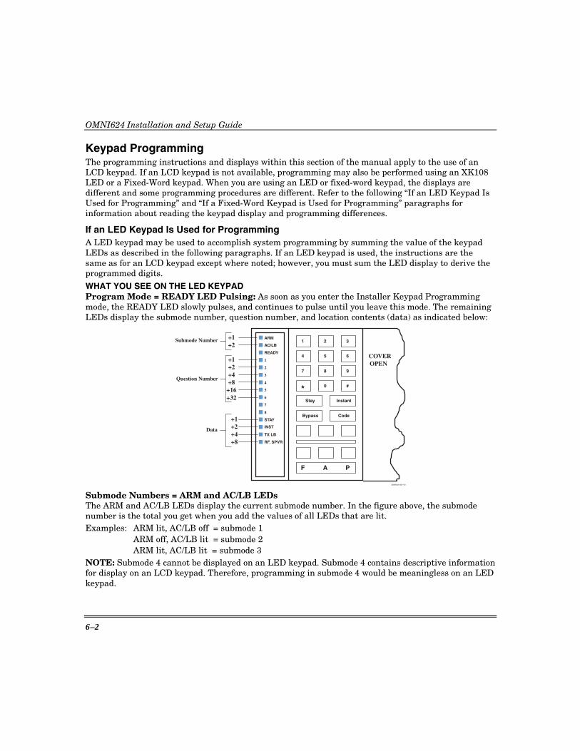
OMNI624 Installation and Setup Guide
6–2
Keypad Programming The programming instructions and displays within this section of the manual apply to the use of an LCD keypad. If an LCD keypad is not available, programming may also be performed using an XK108 LED or a Fixed-Word keypad. When you are using an LED or fixed-word keypad, the displays are different and some programming procedures are different. Refer to the following “If an LED Keypad Is Used for Programming” and “If a Fixed-Word Keypad is Used for Programming” paragraphs for information about reading the keypad display and programming differences.
If an LED Keypad Is Used for Programming A LED keypad may be used to accomplish system programming by summing the value of the keypad LEDs as described in the following paragraphs. If an LED keypad is used, the instructions are the same as for an LCD keypad except where noted; however, you must sum the LED display to derive the programmed digits. WHAT YOU SEE ON THE LED KEYPAD Program Mode = READY LED Pulsing: As soon as you enter the Installer Keypad Programming mode, the READY LED slowly pulses, and continues to pulse until you leave this mode. The remaining LEDs display the submode number, question number, and location contents (data) as indicated below:
ARM
AC/LB
READY
1
2
3
4
5
6
7
8
STAY
INST
COVEROPEN
Stay Instant
Bypass Code
* 0 #
7 8 9
4 5 6
1 2 3
PAF
+1+2+4+8
+16
TX LB
RF. SPVR
+1+2+4+8
Question Number
Data
+1+2
Submode Number
OMNI624-007-V0
+32
Submode Numbers = ARM and AC/LB LEDs The ARM and AC/LB LEDs display the current submode number. In the figure above, the submode number is the total you get when you add the values of all LEDs that are lit. Examples: ARM lit, AC/LB off = submode 1
ARM off, AC/LB lit = submode 2 ARM lit, AC/LB lit = submode 3
NOTE: Submode 4 cannot be displayed on an LED keypad. Submode 4 contains descriptive information for display on an LCD keypad. Therefore, programming in submode 4 would be meaningless on an LED keypad.
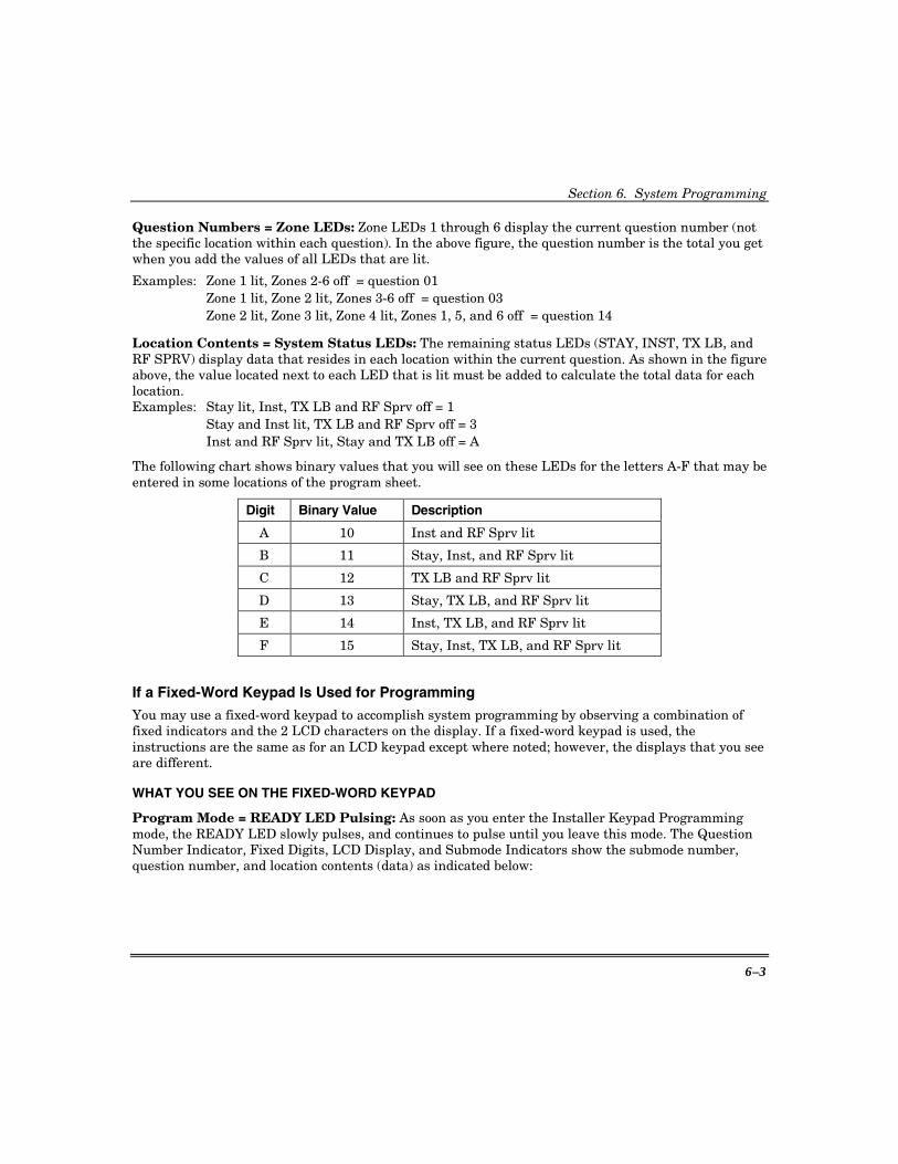
Section 6. System Programming
6–3
Question Numbers = Zone LEDs: Zone LEDs 1 through 6 display the current question number (not the specific location within each question). In the above figure, the question number is the total you get when you add the values of all LEDs that are lit.
Examples: Zone 1 lit, Zones 2-6 off = question 01 Zone 1 lit, Zone 2 lit, Zones 3-6 off = question 03 Zone 2 lit, Zone 3 lit, Zone 4 lit, Zones 1, 5, and 6 off = question 14
Location Contents = System Status LEDs: The remaining status LEDs (STAY, INST, TX LB, and RF SPRV) display data that resides in each location within the current question. As shown in the figure above, the value located next to each LED that is lit must be added to calculate the total data for each location. Examples: Stay lit, Inst, TX LB and RF Sprv off = 1
Stay and Inst lit, TX LB and RF Sprv off = 3 Inst and RF Sprv lit, Stay and TX LB off = A
The following chart shows binary values that you will see on these LEDs for the letters A-F that may be entered in some locations of the program sheet.
Digit Binary Value Description
A 10 Inst and RF Sprv lit
B 11 Stay, Inst, and RF Sprv lit
C 12 TX LB and RF Sprv lit
D 13 Stay, TX LB, and RF Sprv lit
E 14 Inst, TX LB, and RF Sprv lit
F 15 Stay, Inst, TX LB, and RF Sprv lit
If a Fixed-Word Keypad Is Used for Programming
You may use a fixed-word keypad to accomplish system programming by observing a combination of fixed indicators and the 2 LCD characters on the display. If a fixed-word keypad is used, the instructions are the same as for an LCD keypad except where noted; however, the displays that you see are different.
WHAT YOU SEE ON THE FIXED-WORD KEYPAD
Program Mode = READY LED Pulsing: As soon as you enter the Installer Keypad Programming mode, the READY LED slowly pulses, and continues to pulse until you leave this mode. The Question Number Indicator, Fixed Digits, LCD Display, and Submode Indicators show the submode number, question number, and location contents (data) as indicated below:

OMNI624 Installation and Setup Guide
6–4
ALARMFIRE
INSTANT
BYPASS
TRBL PAGE
STAY
SUPRVSN CANCELED
CHIME BATNOT READYPHONE TEST
TAMPER NO AC21
FIXEDDIGITS
SUBMODEINDICATORS
QUESTIONNUMBERINDICATOR
LCDDISPLAY
OMNI624-008-V0
Submode Indicators = STAY, INSTANT, and BYPASS indicators: The STAY, INSTANT, and BYPASS indicators provide the current submode number. The current submode number is as follows:
STAY lit, INSTANT and BYPASS off = submode 1 STAY and INSTANT lit, BYPASS off = submode 2 STAY, INSTANT, and BYPASS lit = submode 3
NOTE: Submode 4 cannot be displayed on a fixed-word keypad. Submode 4 contains descriptive information for display on an LCD keypad. Therefore, programming in submode 4 would be meaningless on a fixed-word keypad.
Question Numbers = ALARM indicator and LCD display: While ALARM is lit, the LCD digits are displaying a question number. When a question number is entered on the keypad, ALARM will light and the LCD digits will display the question number for 2 seconds before automatically changing to a display of the Location and Location Content. ALARM extinguishes when the display switches to Location/Location Content.
Location and Location Contents = Fixed Digits and LCD display: The location number will normally be shown in the first-character position of the 2-character LCD display. However, when the question contains more than 9 locations, the fixed digits will be used with the first LCD character to indicate locations 10 through 19 (fixed digit 1 and the LCD character) or 20 through 29 (fixed digit 2 and the LCD character). While the location number is being displayed, the content of the location is displayed in the second-character position of the 2-character LCD display.
KEY ENTRIES The below listing provides the function of certain key sequences when a fixed-word keypad is used to program the system.
Section 6. System Programming
6–5
KEY ENTRY FUNCTION [#] Advance to the next location within the current question; or advance to the
next question if already displaying the last location in the current question. [✱] + 00–99 Go to a specific question selected by 00 to 99. [CODE] + 1–6 Enter A through F as data where:
[CODE] + [1] = A [CODE] + [4] = D [CODE] + [2] = B [CODE] + [5] = E [CODE] + [3] = C [CODE] + [6] = F
[✱] + [BYPASS] + 1–3 Change mode where: [✱] + [BYPASS] + [1] = submode 1 [✱] + [BYPASS] + [2] = submode 2 [✱] + [BYPASS] + [3] = submode 3
[INSTANT] Advance to the next question. [STAY] Exit the programming mode.
Installer Modes Summary There are 9 installer modes in this panel. TO ENTER INSTALLER MODES, press [CODE] + [✱] + Installer Code + X where: [CODE] CODE button
[✱] Star (✱) button Installer Code 4- or 6-digit Installer Code as programmed; default = 2468 X Single digit indicating the installer mode, as follows:
1 INSTALLER KEYPAD PROGRAMMING 4 submodes: 1- System Options 2- Zone and Report Code Programming 3- Wireless Zone/Keyfob Programming 4- Zone Descriptor Programming (LCD keypads only)
2 PROGRAMMING REVIEW MODE (no changes can be made) 4 submodes: 1- System Options 2- Zone and Report Code Programming 3- Wireless Zone/Keyfob Programming 4- Zone Descriptor Programming (LCD keypads only)
3 WALK TEST WITH REDUCED RF GAIN 4 SYSTEM LOG VIEW (LCD keypads only) 5 SYSTEM DEFAULT 6 CLEAR TAMPER FAULTS (if programmed) 8 UNATTENDED DOWNLOAD 9 ON-LINE DOWNLOADING
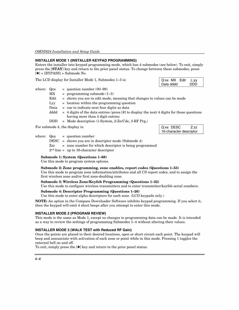
OMNI624 Installation and Setup Guide
6–6
INSTALLER MODE 1 (INSTALLER KEYPAD PROGRAMMING) Enters the installer into keypad programming mode, which has 4 submodes (see below). To exit, simply press the [STAY] key and return to the prior panel status. To change between these submodes, press [✱] + [BYPASS] + Submode No.
The LCD display for Installer Mode 1, Submodes 1–3 is: Q:xx MX Edit L:yy Data dddd DDD
where: Qxx = question number (00–99) MX = programming submode (1–3) Edit = shows you are in edit mode, meaning that changes to values can be made Lyy = location within the programming question Data = cue to indicate next four digits as data dddd = 4 digits of the data entries (press [#] to display the next 4 digits for those questions
having more than 4 digit entries DDD = Mode description (1-System, 2-Zn/Cde, 3-RF Prg,)
For submode 4, the display is: Q:xx DESC Z:zz 16-character descriptor
where: Qxx = question number DESC = shows you are in descriptor mode (Submode 4) Zzz = zone number for which descriptor is being programmed 2nd line = up to 16-character descriptor
Submode 1: System (Questions 1–68) Use this mode to program system options.
Submode 2: Zone programming, zone enables, report codes (Questions 1–53) Use this mode to program zone information/attributes and all CS report codes, and to assign the first wireless zone and/or first zone-doubling zone.
Submode 3: Wireless Zone/Keyfob Programming (Questions 1–32) Use this mode to configure wireless transmitters and to enter transmitter/keyfob serial numbers.
Submode 4: Descriptor Programming (Questions 1–26) Use this mode to enter alpha descriptors for each zone. (LCD keypads only.)
NOTE: An option in the Compass Downloader Software inhibits keypad programming. If you select it, then the keypad will emit 4 short beeps after you attempt to enter this mode.
INSTALLER MODE 2 (PROGRAM REVIEW) This mode is the same as Mode 1, except no changes to programming data can be made. It is intended as a way to review the settings of programming Submodes 1–4 without altering their values.
INSTALLER MODE 3 (WALK TEST with Reduced RF Gain) Once the points are placed in their desired locations, open or short circuit each point. The keypad will beep and annunciate with activation of each zone or point while in this mode. Pressing 1 toggles the external bell on and off. To exit, simply press the [✱] key and return to the prior panel status.

Section 6. System Programming
6–7
INSTALLER MODE 4 (SYSTEM LOG VIEW) The system retains history of the past 128 events (alarms, troubles, openings, closings, bypasses, etc.). Upon entry to the system log view, LCD-based keypads show the events for the entire system, based on the options programmed in Question 17, Locations 1–3. Additionally, the programmed time and date display options are followed. This means the time may be 24-hour or AM/PM format, and the date may have either the day or month displayed first. When the log is viewed through the quick command, the clear log function is blocked. This mode is available only on LCD keypads.
Pressing either the [STAY] or the [✱] key exits this mode. Pressing the [#] key advances to the next valid entry. Pressing the [CODE] key backs up to the previous entry. Pressing the [BYPASS] key clears the system log.
LCD keypads display events as: L 001 ALARM ZN 01 20 APR, 10:38 P1
where: Line 1: event number (L001–L128), event display, zone no. (01–24), or user no. (01–32) Line 2: date, time, partition (1–4) if a partitioned system
Event Displays
Event Display Event Display System Troubles Special Arming System AC Loss Lnnn AC Loss Quick Arm Lnnn Quick Armed System Low Batt Lnnn Batt. Fail Quick Force Arm Lnnn Forced Arm Comm. Fail Lnnn Comm. Fail Stay Key Arm Lnnn Quick Armed CS Test Lnnn CS Test Remote Arm Lnnn Remote Arm System Download Lnnn Downloaded Auto-arm Lnnn Auto-armed Phone Fail Lnnn Phone Fail Instant Arms Away Lnnn Quick Armed Special Alarms Other Events Keypad ✱ & # Lnnn Keypad ✱ & # Alarms Lnnn Alarm Zn xx Keypad 7 & 9 Lnnn Keypad 7 & 9 Troubles Lnnn Troub Zn xx Keypad 1 & 3 Lnnn Keypad 1 & 3 Zone Low Battery Lnnn Lo Bat Zn xx Keypad Duress Lnnn Duress Zone Supervision Lnnn Super Zn xx Keypad Tamper Lnnn Key Tamper Zone Bypass Lnnn Bypas Zn xx Zone Tamper Lnnn Tampr Zn xx Opening Lnnn Opn User xx Closing Lnnn Clo User xx
INSTALLER MODE 5 (SYSTEM DEFAULT)
This mode can initiate a system default. The system will then revert to factory-programmed values and go through the reset sequence and the warm-up time sequence.
INSTALLER MODE 6 (CLEAR TAMPER FAULTS)
This mode clears all tamper displays in all partitions for double balanced and RF zones that have restored, and is an Installer reset function.

OMNI624 Installation and Setup Guide
6–8
INSTALLER MODE 8 (INSTALLER UNATTENDED DOWNLOAD)
For UL installations, Installer Unattended Download may NOT be used. The control panel dials (up to 8 times) the telephone number of the CS Downloading Computer without the need to have the operator present. The CS Downloading computer telephone number (Question 01) and an unattended identification number (Question 02) in the Downloader Software will be programmed into dedicated memory locations.
Unattended download requires the following sequence:
NOTE: Prior to entering this mode, the PC operator must know the unattended identification number for each panel to be downloaded and modem phone number for the CS Downloading computer.
1. The PC operator must select UNATTENDED DOWNLOAD in the Downloader Software Main Menu.
2. Enter unattended download mode: [CODE] + [✱] + Installer Code + [8].
3. The system will now enter keypad programming, Question 01. Enter the telephone number of the central station downloading computer (each digit followed by the [#] key; e.g., [1] [#] [2] [#] [3] [#] etc.) into this question (20 digits max). This phone number should be the same as the CS callback number (Question 03 from keypad programming if the panel is programmed for callback).
4. Press the [INSTANT] key to proceed to Question 02. Next, enter the desired unattended identification number (each digit followed by the [#] key). This will be used by the Compass software in the CS downloading computer to determine the proper account information to download to this subscriber. The unattended identification number must be 12 digits in length. It is the unattended identification number (not the account number) that will be communicated to the Compass software in the CS downloading computer. For unattended identification numbers fewer than 12 digits, you must enter leading 0's to make the number 12 digits long.
Example: for unattended identification number 345, enter 0 # 0 # 0 # 0 # 0 # 0 # 0 # 0 # 0 # 3 # 4 # 5 #
5. Press the [STAY] key to exit programming mode. The control panel will now dial the telephone number entered into the callback number. The downloading computer must be placed into the Unattended Communications option from the main menu. Upon connection with the computer, the system will obtain the unattended identification number programmed in step 4 and perform the desired download operation.
NOTE: The CS downloading computer must be waiting in the Unattended Communications mode and preprogrammed with the account information in order for the unattended download to be functional.
UL The unattended download mode CANNOT be used in UL installations.
INSTALLER MODE 9 (ON-LINE DOWNLOAD)
In this mode, the installer can initiate a remote communications session with the CS Downloading computer at the control panel location. Typically, the CS initiates a remote communications session. On-line Downloading allows the installer to call the office (from the same telephone line as the panel),
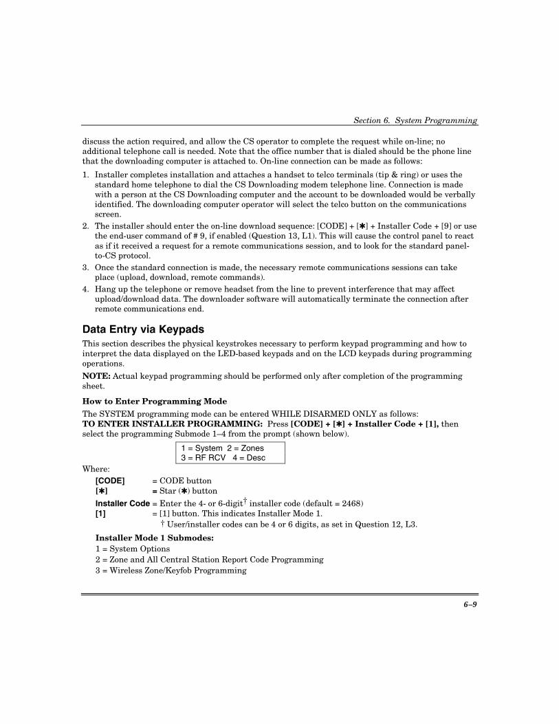
Section 6. System Programming
6–9
discuss the action required, and allow the CS operator to complete the request while on-line; no additional telephone call is needed. Note that the office number that is dialed should be the phone line that the downloading computer is attached to. On-line connection can be made as follows:
1. Installer completes installation and attaches a handset to telco terminals (tip & ring) or uses the standard home telephone to dial the CS Downloading modem telephone line. Connection is made with a person at the CS Downloading computer and the account to be downloaded would be verbally identified. The downloading computer operator will select the telco button on the communications screen.
2. The installer should enter the on-line download sequence: [CODE] + [✱] + Installer Code + [9] or use the end-user command of # 9, if enabled (Question 13, L1). This will cause the control panel to react as if it received a request for a remote communications session, and to look for the standard panel-to-CS protocol.
3. Once the standard connection is made, the necessary remote communications sessions can take place (upload, download, remote commands).
4. Hang up the telephone or remove headset from the line to prevent interference that may affect upload/download data. The downloader software will automatically terminate the connection after remote communications end.
Data Entry via Keypads This section describes the physical keystrokes necessary to perform keypad programming and how to interpret the data displayed on the LED-based keypads and on the LCD keypads during programming operations. NOTE: Actual keypad programming should be performed only after completion of the programming sheet.
How to Enter Programming Mode The SYSTEM programming mode can be entered WHILE DISARMED ONLY as follows: TO ENTER INSTALLER PROGRAMMING: Press [CODE] + [✱] + Installer Code + [1], then select the programming Submode 1–4 from the prompt (shown below).
1 = System 2 = Zones 3 = RF RCV 4 = Desc
Where: [CODE] = CODE button [✱] = Star (✱) button
Installer Code = Enter the 4- or 6-digit† installer code (default = 2468) [1] = [1] button. This indicates Installer Mode 1.
† User/installer codes can be 4 or 6 digits, as set in Question 12, L3. Installer Mode 1 Submodes: 1 = System Options 2 = Zone and All Central Station Report Code Programming 3 = Wireless Zone/Keyfob Programming
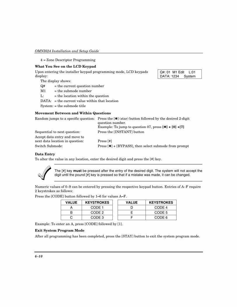
OMNI624 Installation and Setup Guide
6–10
4 = Zone Descriptor Programming
What You See on the LCD Keypad Upon entering the installer keypad programming mode, LCD keypads display:
Q#: 01 M1 Edit L:01 DATA: 1234 System
The display shows: Q# = the current question number M1 = the submode number L: = the location within the question DATA: = the current value within that location System: = the submode title
Movement Between and Within Questions Random jumps to a specific question: Press the [✱] (star) button followed by the desired 2-digit
question number. Example: To jump to question 07, press [✱] + [0] +[7] Sequential to next question: Press the [INSTANT] button Accept data entry and move to next data location in question: Press [#] Switch Submode: Press [✱] + [BYPASS], then select submode from prompt
Data Entry To alter the value in any location, enter the desired digit and press the [#] key.
The [#] key must be pressed after the entry of the desired digit. The system will not accept thedigit until the pound [#] key is pressed so that if a mistake was made, it can be changed.
Numeric values of 0–9 can be entered by pressing the respective keypad button. Entries of A–F require 2 keystrokes as follows:
Press the [CODE] button followed by 1–6 for values A–F.
VALUE KEYSTROKES VALUE KEYSTROKES A CODE 1 D CODE 4 B CODE 2 E CODE 5 C CODE 3 F CODE 6
Example: To enter an A, press [CODE] followed by [1].
Exit System Program Mode
After all programming has been completed, press the [STAY] button to exit the system program mode.

Section 6. System Programming
6–11
Question Acknowledgment
The keypad will beep between keystrokes. In addition, a beep will be generated confirming advancement between question numbers. Four beeps will be generated if an invalid input is entered. Upon entry of an invalid input, you remain at the same question number and location as prior to the input error.
To Enter Programming: [CODE] + [✱] + 4- or 6-digit Installer Code + [1] +submode 1–4
To Skip a Question: [✱] + 2-digit Question Number
To Move Within a Question: Press the [#] until the desired location is reached
To Enter Data: single digit: 0–9, A–F + [#]
Hexadecimal Entries: A = [CODE] [1] D = [CODE] [4] B = [CODE] [2] E = [CODE] [5] C = [CODE] [3] F = [CODE] [6]
To Exit Programming: Press the [STAY] button
Summary of System Programming
Installer Mode 1: Programming Questions This section defines the programming questions and the values for each question. You should complete the SYSTEM PROGRAMMING WORKSHEET (insert) before entering data.
Programming Submode 1: SYSTEM OPTIONS Enter Installer Programming mode, then press [1] at the submode prompt to enter System Options submode.
QUESTION 00 INSTALLER CODE N/U N/U
L1 L2 L3 L4 L5 L6 L7 L8 NOTE: When Programming Submode 1 is entered, the System automatically displays Question 01. To display this question for review and/or modification of the Installer Code, you enter [✱] + [0] + [0]. Enter the 4- or 6-digit Installer Code in Question 00 locations L1–L4 for a 4-digit code or L1–L6 for a 6-digit code. When using a 4-digit code, L4 and L5 may be left at the default value of “0”. IMPORTANT: When using a 6-digit code, enter the third through sixth digits of the code in L1–L4 respectively and the first and second digits in L5 and L6 respectively. For example:
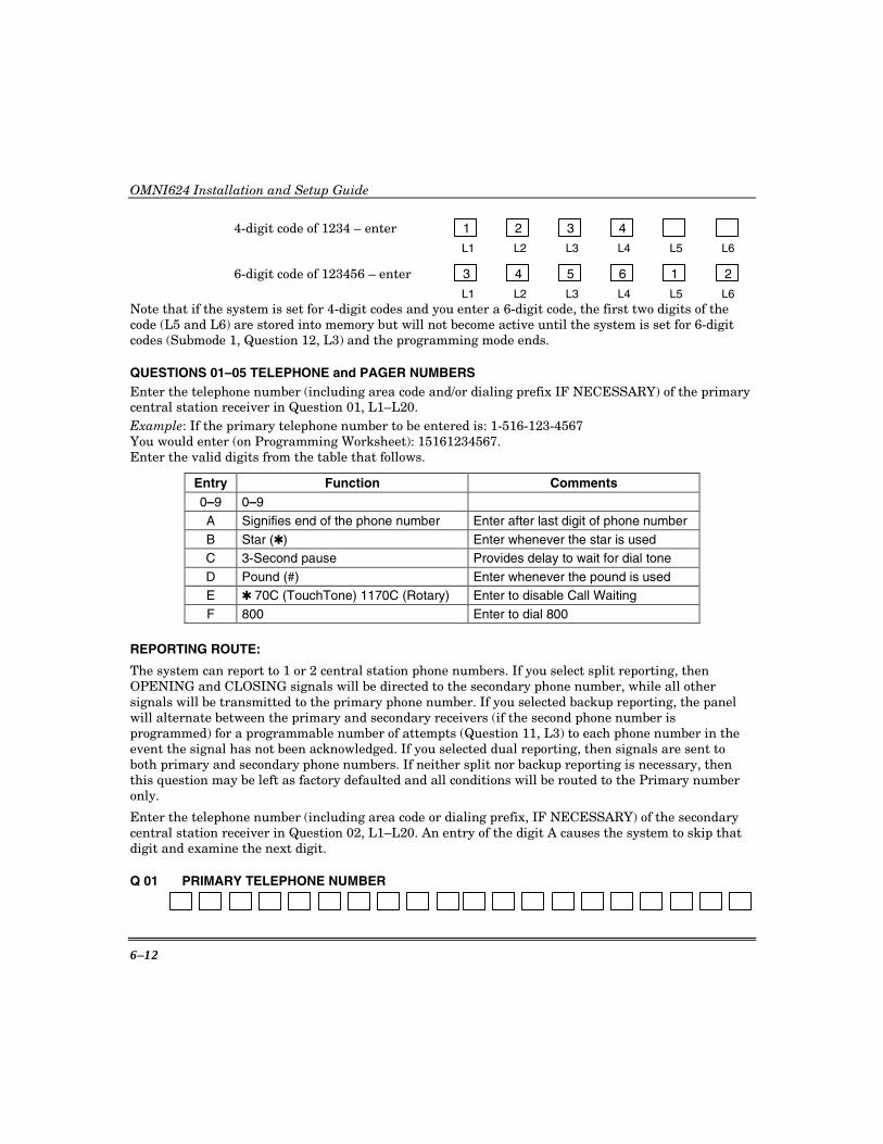
OMNI624 Installation and Setup Guide
6–12
4-digit code of 1234 – enter 1 2 3 4
L1 L2 L3 L4 L5 L6
6-digit code of 123456 – enter 3 4 5 6 1 2
L1 L2 L3 L4 L5 L6 Note that if the system is set for 4-digit codes and you enter a 6-digit code, the first two digits of the code (L5 and L6) are stored into memory but will not become active until the system is set for 6-digit codes (Submode 1, Question 12, L3) and the programming mode ends.
QUESTIONS 01–05 TELEPHONE and PAGER NUMBERS Enter the telephone number (including area code and/or dialing prefix IF NECESSARY) of the primary central station receiver in Question 01, L1–L20. Example: If the primary telephone number to be entered is: 1-516-123-4567 You would enter (on Programming Worksheet): 15161234567. Enter the valid digits from the table that follows.
Entry Function Comments 0–9 0–9
A Signifies end of the phone number Enter after last digit of phone number B Star (✱) Enter whenever the star is used C 3-Second pause Provides delay to wait for dial tone D Pound (#) Enter whenever the pound is used E ✱ 70C (TouchTone) 1170C (Rotary) Enter to disable Call Waiting F 800 Enter to dial 800
REPORTING ROUTE:
The system can report to 1 or 2 central station phone numbers. If you select split reporting, then OPENING and CLOSING signals will be directed to the secondary phone number, while all other signals will be transmitted to the primary phone number. If you selected backup reporting, the panel will alternate between the primary and secondary receivers (if the second phone number is programmed) for a programmable number of attempts (Question 11, L3) to each phone number in the event the signal has not been acknowledged. If you selected dual reporting, then signals are sent to both primary and secondary phone numbers. If neither split nor backup reporting is necessary, then this question may be left as factory defaulted and all conditions will be routed to the Primary number only.
Enter the telephone number (including area code or dialing prefix, IF NECESSARY) of the secondary central station receiver in Question 02, L1–L20. An entry of the digit A causes the system to skip that digit and examine the next digit.
Q 01 PRIMARY TELEPHONE NUMBER

Section 6. System Programming
6–13
Q 02 SECONDARY TELEPHONE NUMBER
Q 03 CALLBACK TELEPHONE NUMBER
Enter the telephone number (including area code or dialing prefix, if necessary) for this control panel to reach the callback number location. The callback number is the optional location of the Downloading Software where the control panel will call during a remote communications (upload/download etc.) session. During remote communications, the programming device and the control panel will first confirm the CS security code. If valid, communications can begin. If a callback number is defined, the control panel will hang up and dial the callback number. For no callback capability, enter “A” in L1–L20.
Q 04 PAGER PARTITION 1 TELEPHONE NUMBER
Enter the pager number for reports from partition 1, up to 16 digits (including area code or dialing prefix, if necessary). For no partition 1 pager report, enter “A” in L1–L16.
Q 05 PAGER PARTITION 2 TELEPHONE NUMBER
Enter the pager number for reports from partition 2, up to 16 digits (including area code or dialing prefix, if necessary). For no partition 2 pager report, enter “A” in L1–L16.
QUESTIONS 06–09 ACCOUNT NUMBERS
Primary account: Enter the 3- or 4-digit subscriber account numbers for central station phone number 1 in Questions 06 (partition 1) and 08 (partition 2) locations L1–L4. If a 3-digit number is used, then enter an “A” in location L4. Valid entries are 0–9, and B–F.
Secondary account: Enter the 3- or 4-digit subscriber account numbers for Central Station phone number 2 in Questions 07 (partition 1) and 09 (partition 2) locations L1–L4. If the second phone number is not used, this question can be left at the factory default of all “A’s.”
THIS ACCOUNT NUMBER MUST BE ENTERED IF YOU HAVE PROGRAMMED A SECOND RECEIVER PHONE NUMBER FOR BACKUP/SPLIT REPORTING AND DUAL REPORTING.
Q 06 PRIMARY ACCOUNT NUMBER PARTITION 1
L1 L2 L3 L4
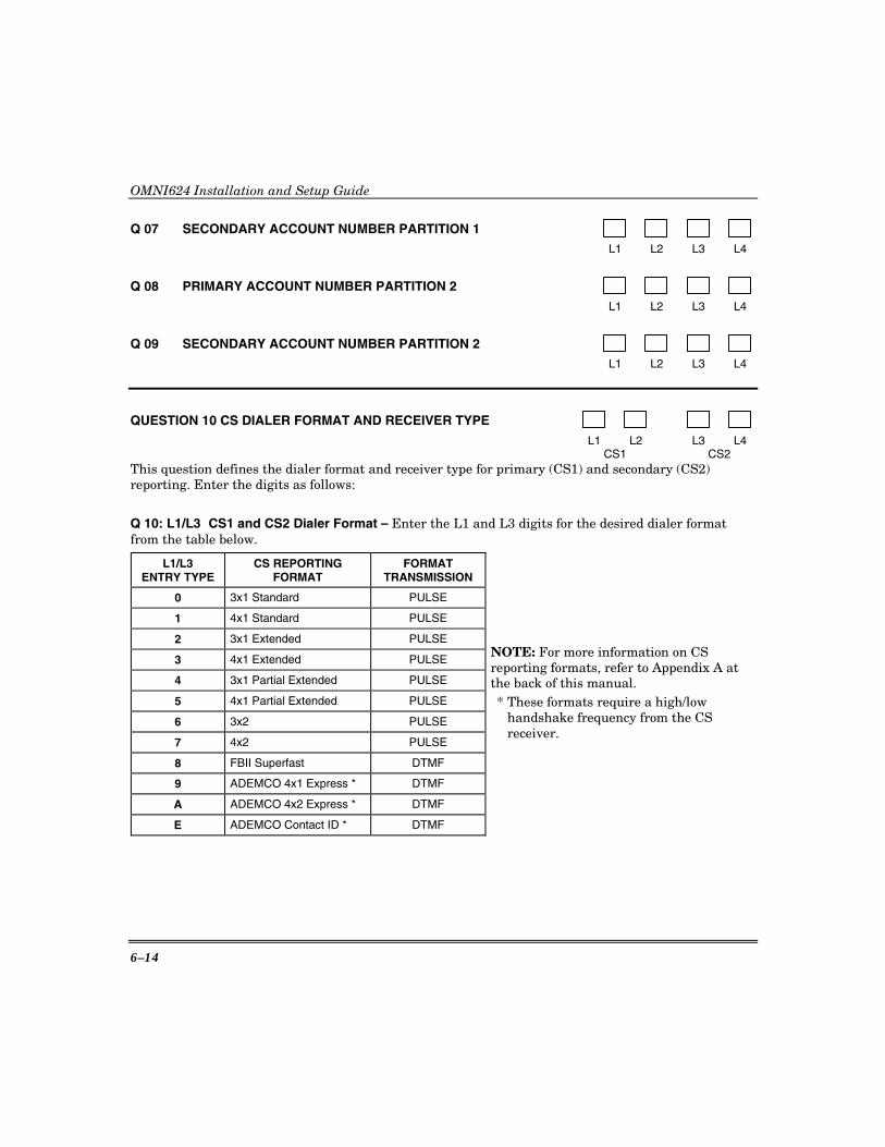
OMNI624 Installation and Setup Guide
6–14
Q 07 SECONDARY ACCOUNT NUMBER PARTITION 1
L1 L2 L3 L4
Q 08 PRIMARY ACCOUNT NUMBER PARTITION 2
L1 L2 L3 L4
Q 09 SECONDARY ACCOUNT NUMBER PARTITION 2
L1 L2 L3 L4
QUESTION 10 CS DIALER FORMAT AND RECEIVER TYPE
L1 L2 L3 L4 CS1 CS2 This question defines the dialer format and receiver type for primary (CS1) and secondary (CS2) reporting. Enter the digits as follows:
Q 10: L1/L3 CS1 and CS2 Dialer Format – Enter the L1 and L3 digits for the desired dialer format from the table below.
L1/L3 ENTRY TYPE
CS REPORTING FORMAT
FORMAT TRANSMISSION
0 3x1 Standard PULSE
1 4x1 Standard PULSE
2 3x1 Extended PULSE
3 4x1 Extended PULSE
4 3x1 Partial Extended PULSE
5 4x1 Partial Extended PULSE
6 3x2 PULSE
7 4x2 PULSE
8 FBII Superfast DTMF
9 ADEMCO 4x1 Express * DTMF
A ADEMCO 4x2 Express * DTMF
E ADEMCO Contact ID * DTMF
NOTE: For more information on CS reporting formats, refer to Appendix A at the back of this manual. * These formats require a high/low
handshake frequency from the CS receiver.
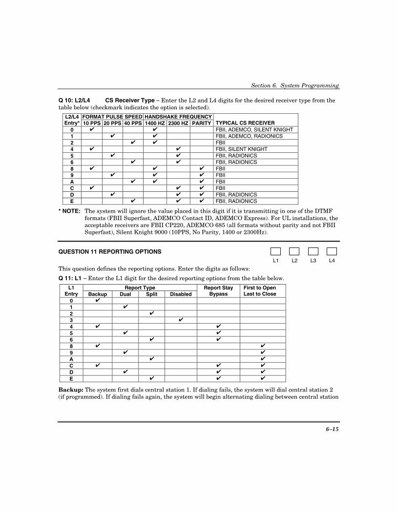
Section 6. System Programming
6–15
Q 10: L2/L4 CS Receiver Type – Enter the L2 and L4 digits for the desired receiver type from the table below (checkmark indicates the option is selected).
FORMAT PULSE SPEED HANDSHAKE FREQUENCYL2/L4 Entry* 10 PPS 20 PPS 40 PPS 1400 HZ 2300 HZ PARITY TYPICAL CS RECEIVER
0 ✔ ✔ FBII, ADEMCO, SILENT KNIGHT 1 ✔ ✔ FBII, ADEMCO, RADIONICS 2 ✔ ✔ FBII 4 ✔ ✔ FBII, SILENT KNIGHT 5 ✔ ✔ FBII, RADIONICS 6 ✔ ✔ FBII, RADIONICS 8 ✔ ✔ ✔ FBII 9 ✔ ✔ ✔ FBII A ✔ ✔ ✔ FBII C ✔ ✔ ✔ FBII D ✔ ✔ ✔ FBII, RADIONICS E ✔ ✔ ✔ FBII, RADIONICS
* NOTE: The system will ignore the value placed in this digit if it is transmitting in one of the DTMF formats (FBII Superfast, ADEMCO Contact ID, ADEMCO Express). For UL installations, the acceptable receivers are FBII CP220, ADEMCO 685 (all formats without parity and not FBII Superfast), Silent Knight 9000 (10PPS, No Parity, 1400 or 2300Hz).
QUESTION 11 REPORTING OPTIONS L1 L2 L3 L4
This question defines the reporting options. Enter the digits as follows:
Q 11: L1 – Enter the L1 digit for the desired reporting options from the table below.
Report Type L1 Entry Backup Dual Split Disabled
Report Stay Bypass
First to Open Last to Close
0 ✔
1 ✔
2 ✔
3 ✔
4 ✔ ✔
5 ✔ ✔
6 ✔ ✔
8 ✔ ✔
9 ✔ ✔
A ✔ ✔
C ✔ ✔ ✔
D ✔ ✔ ✔
E ✔ ✔ ✔
Backup: The system first dials central station 1. If dialing fails, the system will dial central station 2 (if programmed). If dialing fails again, the system will begin alternating dialing between central station

OMNI624 Installation and Setup Guide
6–16
1 and central station 2 until contact is established or the maximum number of dialing attempts (see Question 11, Location 3) expires. Dual: Events will be sent to both central station phone numbers. Split Reporting: If split reporting is enabled, then all reports other than openings and closings will be sent to CS#1. Openings/closings will be transmitted to CS#2. Dialer Disable: This option will turn OFF the digital dialer, making the control a local panel. The Dialer Disable selection shall not be selected for UL installations. Report Stay Bypass: This option specifies that bypasses will be transmitted upon Stay or Auto Stay arming. If this option is selected, then bypasses will be transmitted for each Stay/Auto Stay zone that has been bypassed with STAY or Auto Stay arming. NOTE: Bypasses will be transmitted only if there is a bypass code defined (see Submode 2, Question 44, L1). First to Open/Last to Close: If selected, open/close reports are only sent after all partitions are armed/disarmed. The open report will indicate only the partition that first disarmed the system. The close report will indicate only the partition that was the last to arm the system (thus causing all partitions to be armed).
Q 11, L2 Restore Reporting – Enter the digit for the type of Restore reports to be sent. Program the actual Restore report codes in Submode 2, Question 47.
L2 Entry
Supervision Restore
Tamper Restore
RF Low Bat. Restore
0 1 ✔ 2 ✔ 3 ✔ ✔ 4 ✔ 5 ✔ ✔
6 ✔ ✔ 7 ✔ ✔ ✔
Q 11, L3 CS Dialer Attempts – This option selects the number of times the communicator will attempt to dial both CS receivers. If CS #2 is not programmed, then this option determines the dialer attempts to CS #1. Enter the number of attempts, 1–15.
NOTE: This is valid for all CS receiver formats. Enter a digit from the table that follows. L3
Entry Dialer
Attempts L3
Entry Dialer
Attempts
0 1 8 8 1 1 9 9 2 2 A 10 3 3 B 11
UL For UL installations you must select a value between 5 and 10.
4 4 C 12 5 5 D 13 6 6 E 14 7 7 F 15

Section 6. System Programming
6–17
Q 11, L4 Restore Reporting – Enter the digit for the type of Restore reports to be sent. Program the actual trouble Restore report code in Submode 2, Question 44, Location 4. Program the actual zone Restore report code in Submode 2, Question 44, Location 2.
L4 Entry
Send AC Restore
Send Low Bat. Restore
Send Zone Restore
Restore Follows Loop
0 1 ✔ 2 ✔ 3 ✔ ✔ 4 ✔ 5 ✔ ✔ 6 ✔ ✔ 7 ✔ ✔ ✔ C ✔ ✔ D ✔ ✔ ✔ E ✔ ✔ ✔ F ✔ ✔ ✔ ✔
Send Zone Restore & Restore Follows Loop: Normally, zone restores are sent at bell cutoff, when the panel is disarmed, and when the panel is reset. If you select Restore Follows Loop, zone Restore reports will be sent as soon as the zone restores.
QUESTION 12 SYSTEM OPTIONS
L1 L2 L3 L4
This question defines various system-wide options.
Q 12, L1 – Enter the L1 digit for the desired options from the table that follows.
L1 Entry
No Bell if Dial Delay
Fast Zones
5/6
Double-Balanced
Zones 0 1 ✔ 2 ✔ 3 ✔ ✔ 4 ✔ 5 ✔ ✔ 6 ✔ ✔ 7 ✔ ✔ ✔ 8 9 ✔ A ✔ B ✔ ✔
C ✔
D ✔ ✔
E ✔ ✔
F ✔ ✔ ✔
No Bell if Dial Delay: If selected, bell sounding will not occur until the dialer is activated (bell is delayed by the same amount of time as the dial delay setting). See Question 19, Location 4 for setting the dial delay (15–255 seconds) and Submode 2, Questions 1–24, Location 4 to enable the dial delay for each zone. Fast Zones 5/6: Sets zones 5 and 6 to fast response (10mS). If set, these zones must be wired as NC loops (cannot be double-balanced zones or part of zone doubling). Double-Balanced Zones: Select if using double-balanced zones. This option allows hardwired zones to be wired such that a tamper will be detected on an open or a shorted loop.
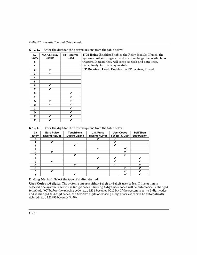
OMNI624 Installation and Setup Guide
6–18
Q 12, L2 – Enter the digit for the desired options from the table below.
L2 Entry
XL4705 Relay Enable
RF Receiver Used
0
1
2 ✔
3 ✔
4
5
6 ✔
7 ✔
8 ✔
9 ✔
A ✔ ✔
B ✔ ✔
C ✔
D ✔
E ✔ ✔
F ✔ ✔
4705 Relay Enable: Enables the Relay Module. If used, the system’s built-in triggers 3 and 4 will no longer be available as triggers. Instead, they will serve as clock and data lines, respectively, for the relay module. RF Receiver Used: Enables the RF receiver, if used.
Q 12, L3 – Enter the digit for the desired options from the table below.
User Codes L3 Entry
Euro Pulse Dialing (66:33)
TouchTone (DTMF) Dialing
U.S. Pulse Dialing (60:40) 4-Digit 6-Digit
Bell/Siren Supervision
0 ✔ ✔ 1 ✔ ✔ 2 ✔ ✔ 4 ✔ ✔ 5 ✔ ✔ 6 ✔ ✔ 8 ✔ ✔ ✔
9 ✔ ✔ ✔
A ✔ ✔ ✔
C ✔ ✔ ✔
D ✔ ✔ ✔
E ✔ ✔ ✔
Dialing Method: Select the type of dialing desired. User Codes 4/6 digits: The system supports either 4-digit or 6-digit user codes. If this option is selected, the system is set to use 6-digit codes. Existing 4-digit user codes will be automatically changed to include “00” before the existing code (e.g., 1234 becomes 001234). If the system is set to 6-digit codes and is changed to 4-digit codes, the first two digits of existing 6-digit user codes will be automatically deleted (e.g., 123456 becomes 3456).
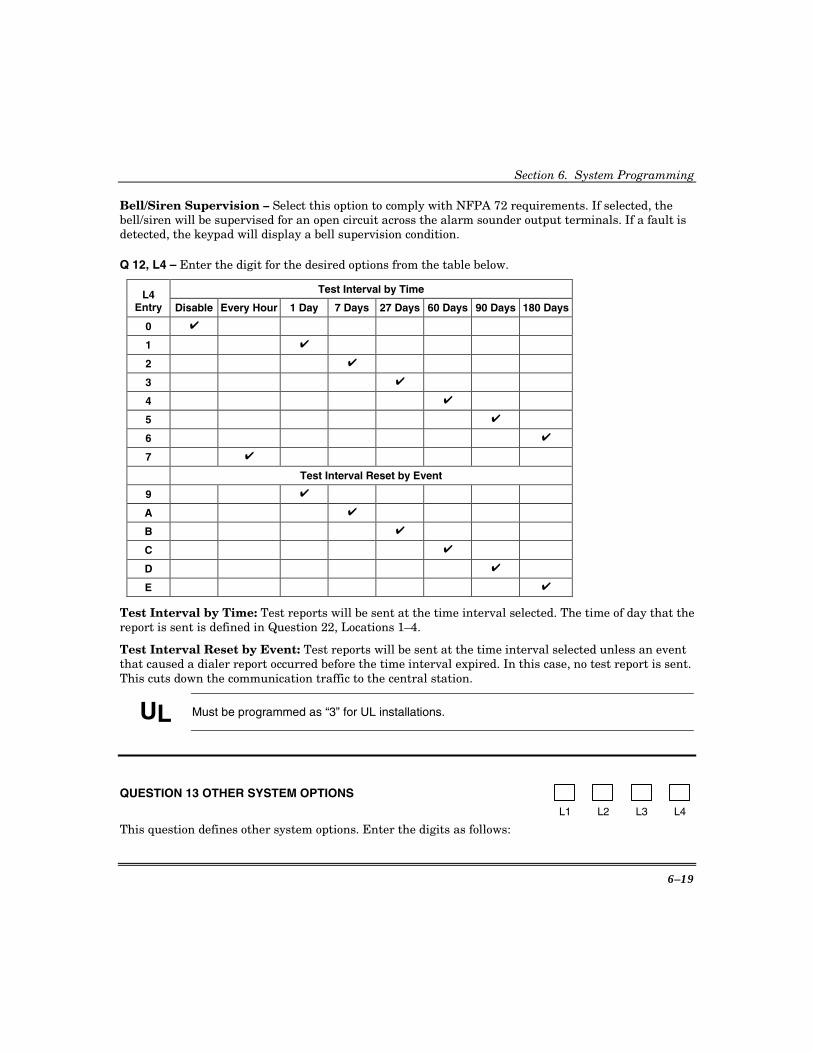
Section 6. System Programming
6–19
Bell/Siren Supervision – Select this option to comply with NFPA 72 requirements. If selected, the bell/siren will be supervised for an open circuit across the alarm sounder output terminals. If a fault is detected, the keypad will display a bell supervision condition.
Q 12, L4 – Enter the digit for the desired options from the table below.
Test Interval by Time L4 Entry Disable Every Hour 1 Day 7 Days 27 Days 60 Days 90 Days 180 Days
0 ✔
1 ✔
2 ✔
3 ✔
4 ✔
5 ✔
6 ✔
7 ✔
Test Interval Reset by Event
9 ✔
A ✔
B ✔
C ✔
D ✔
E ✔
Test Interval by Time: Test reports will be sent at the time interval selected. The time of day that the report is sent is defined in Question 22, Locations 1–4.
Test Interval Reset by Event: Test reports will be sent at the time interval selected unless an event that caused a dialer report occurred before the time interval expired. In this case, no test report is sent. This cuts down the communication traffic to the central station.
UL Must be programmed as “3” for UL installations.
QUESTION 13 OTHER SYSTEM OPTIONS
L1 L2 L3 L4
This question defines other system options. Enter the digits as follows:
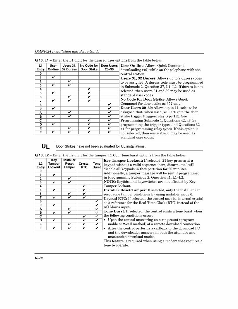
OMNI624 Installation and Setup Guide
6–20
Q 13, L1 – Enter the L1 digit for the desired user options from the table below. L1
Entry User
On-line Users 31, 32 Duress
No Code for Door Strike
Door Users 20–30
0
1 ✔
2 ✔
3 ✔ ✔
4 ✔
5 ✔ ✔
6 ✔ ✔
7 ✔ ✔ ✔
8 ✔
9 ✔ ✔
A ✔ ✔
B ✔ ✔ ✔
C ✔ ✔
D ✔ ✔ ✔
E ✔ ✔ ✔
F ✔ ✔ ✔ ✔
User On-line: Allows Quick Command downloading (#9) while on the telephone with the central station. Users 31, 32 Duress: Allows up to 2 duress codes to be assigned. A duress code must be programmedin Submode 2, Question 37, L1–L2. If duress is not selected, then users 31 and 32 may be used as standard user codes. No Code for Door Strike: Allows Quick Command for door strike as #57 only. Door Users 20–30: Allows up to 11 codes to be assigned that, when used, will activate the door strike trigger (trigger/relay type 1E). See Programming Submode 1, Questions 42, 43 for programming the trigger types and Questions 32–41 for programming relay types. If this option is not selected, then users 20–30 may be used as standard user codes.
UL Door Strikes have not been evaluated for UL installations.
Q 13, L2 – Enter the L2 digit for the tamper, RTC, or tone burst options from the table below.
L2 Entry
Key Tamper Lockout
Installer Reset
Tamper Crystal
RTC Tone Burst
0
1 ✔
2 ✔
3 ✔ ✔
4 ✔
5 ✔ ✔
6 ✔ ✔
7 ✔ ✔ ✔
8 ✔
9 ✔ ✔
A ✔ ✔
B ✔ ✔ ✔
C ✔ ✔
D ✔ ✔ ✔
E ✔ ✔ ✔
F ✔ ✔ ✔ ✔
Key Tamper Lockout: If selected, 21 key presses at a keypad without a valid sequence (arm, disarm, etc.) will disable all keypads in that partition for 20 minutes. Additionally, a tamper message will be sent if programmed in Programming Submode 2, Question 41, L1–L2. NOTE: Keyfobs and keyswitches are not affected by Key Tamper Lockout. Installer Reset Tamper: If selected, only the installer can reset zone tamper conditions by using installer mode 6. Crystal RTC: If selected, the control uses its internal crystalas a reference for the Real Time Clock (RTC) instead of the AC Mains input. Tone Burst: If selected, the control emits a tone burst when the following conditions occur: • Upon the control answering on a ring count (program-
mable or 2-call method) of a remote download connection. • After the control performs a callback to the download PC
and the downloader answers in both the attended and unattended download modes.
This feature is required when using a modem that requires a tone to operate.
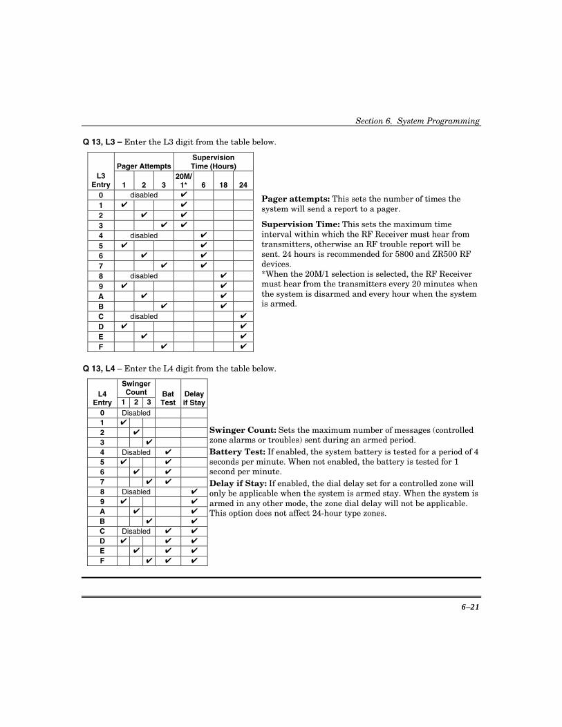
Section 6. System Programming
6–21
Q 13, L3 – Enter the L3 digit from the table below.
Pager AttemptsSupervision Time (Hours)
L3 Entry 1 2 3
20M/1* 6 18 24
0 disabled ✔
1 ✔ ✔
2 ✔ ✔
3 ✔ ✔
4 disabled ✔
5 ✔ ✔
6 ✔ ✔
7 ✔ ✔
8 disabled ✔
9 ✔ ✔
A ✔ ✔
B ✔ ✔
C disabled ✔
D ✔ ✔
E ✔ ✔
F ✔ ✔
Pager attempts: This sets the number of times the system will send a report to a pager.
Supervision Time: This sets the maximum time interval within which the RF Receiver must hear from transmitters, otherwise an RF trouble report will be sent. 24 hours is recommended for 5800 and ZR500 RF devices. *When the 20M/1 selection is selected, the RF Receiver must hear from the transmitters every 20 minutes when the system is disarmed and every hour when the system is armed.
Q 13, L4 – Enter the L4 digit from the table below.
Swinger Count L4
Entry 1 2 3 BatTest
Delay if Stay
0 Disabled 1 ✔ 2 ✔ 3 ✔ 4 Disabled ✔ 5 ✔ ✔ 6 ✔ ✔ 7 ✔ ✔ 8 Disabled ✔ 9 ✔ ✔ A ✔ ✔ B ✔ ✔ C Disabled ✔ ✔ D ✔ ✔ ✔ E ✔ ✔ ✔ F ✔ ✔ ✔
Swinger Count: Sets the maximum number of messages (controlled zone alarms or troubles) sent during an armed period. Battery Test: If enabled, the system battery is tested for a period of 4 seconds per minute. When not enabled, the battery is tested for 1 second per minute. Delay if Stay: If enabled, the dial delay set for a controlled zone will only be applicable when the system is armed stay. When the system is armed in any other mode, the zone dial delay will not be applicable. This option does not affect 24-hour type zones.
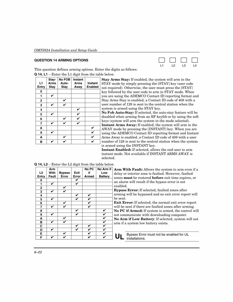
OMNI624 Installation and Setup Guide
6–22
QUESTION 14 ARMING OPTIONS
L1 L2 L3 L4 This question defines arming options. Enter the digits as follows: Q 14, L1 – Enter the L1 digit from the table below.
L1 Entry
Stay-Arms Stay
No FOB Auto-Stay
Instant Arms Away
Instant Enabled
0
1 ✔
2 ✔
3 ✔ ✔
4 ✔
5 ✔ ✔
6 ✔ ✔
7 ✔ ✔ ✔
8 ✔
9 ✔ ✔
A ✔ ✔
B ✔ ✔ ✔
Stay Arms Stay: If enabled, the system will arm in the STAY mode by simply pressing the [STAY] key (user code not required). Otherwise, the user must press the [STAY] key followed by the user code to arm in STAY mode. When you are using the ADEMCO Contact ID reporting format and Stay Arms Stay is enabled, a Contact ID code of 408 with a user number of 128 is sent to the central station when the system is armed using the STAY key. No Fob Auto-Stay: If selected, the auto-stay feature will be disabled when arming from an RF keyfob or by using the soft keys (system will arm the system in the mode selected). Instant Arms Away: If enabled, the system will arm in the AWAY mode by pressing the [INSTANT] key. When you are using the ADEMCO Contact ID reporting format and Instant Arms Away is enabled, a Contact ID code of 408 with a user number of 128 is sent to the central station when the system is armed using the INSTANT key. Instant Enabled: If selected, allows the end user to arm instant mode. Not available if INSTANT ARMS AWAY is selected.
Q 14, L2 – Enter the L2 digit from the table below.
L2 Entry
Arm With Fault
BypassError
Exit Error
No PC if
Armed
No Arm ifLow
Battery 0 ✔
1 ✔ ✔
2 ✔
3 ✔ ✔
4 ✔ ✔
5 ✔ ✔ ✔
6 ✔ ✔
7 ✔ ✔ ✔
8 ✔ ✔
9 ✔ ✔ ✔
A ✔ ✔
B ✔ ✔ ✔
C ✔ ✔ ✔
D ✔ ✔ ✔ ✔
Arm With Fault: Allows the system to arm even if a delay or interior zone is faulted. However, faulted zones must be restored before exit time expires, or an alarm will result if the bypass error is not enabled. Bypass Error: If selected, faulted zones after arming will be bypassed and no exit error report will be sent. Exit Error: If selected, the normal exit error report will be sent if there are faulted zones after arming. No PC if Armed: If system is armed, the control will not communicate with downloading computer. No Arm if Low Battery: If selected, system will not arm if a system low battery exists.
E ✔ ✔ ✔
F ✔ ✔ ✔ ✔
UL Bypass Error must not be enabled for UL installations.
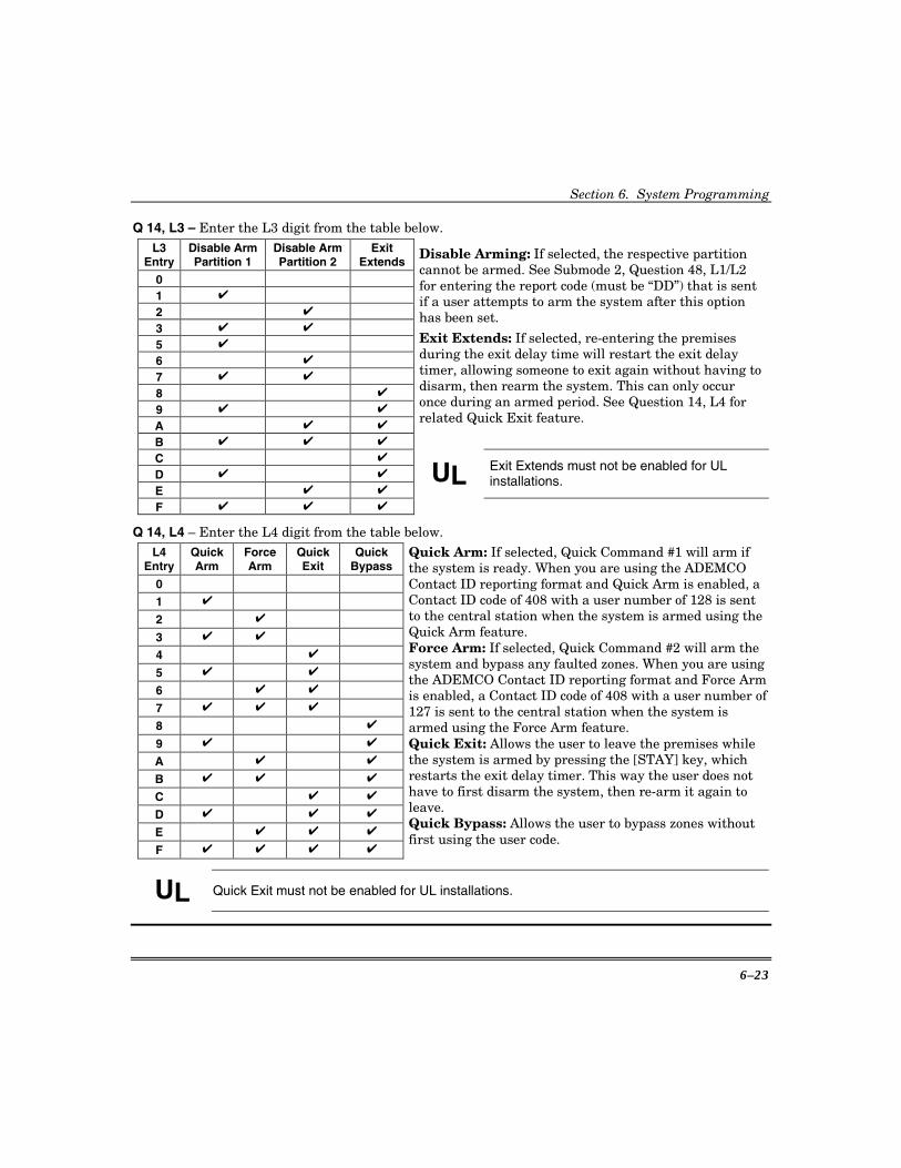
Section 6. System Programming
6–23
Q 14, L3 – Enter the L3 digit from the table below. L3
Entry Disable Arm Partition 1
Disable Arm Partition 2
Exit Extends
0
1 ✔
2 ✔
3 ✔ ✔
5 ✔
6 ✔
7 ✔ ✔
8 ✔
9 ✔ ✔
A ✔ ✔
B ✔ ✔ ✔
Disable Arming: If selected, the respective partition cannot be armed. See Submode 2, Question 48, L1/L2 for entering the report code (must be “DD”) that is sent if a user attempts to arm the system after this option has been set.
Exit Extends: If selected, re-entering the premises during the exit delay time will restart the exit delay timer, allowing someone to exit again without having to disarm, then rearm the system. This can only occur once during an armed period. See Question 14, L4 for related Quick Exit feature.
C ✔
D ✔ ✔
E ✔ ✔ UL
Exit Extends must not be enabled for UL installations.
F ✔ ✔ ✔
Q 14, L4 – Enter the L4 digit from the table below. L4
Entry Quick Arm
Force Arm
Quick Exit
Quick Bypass
0
1 ✔
2 ✔
3 ✔ ✔
4 ✔
5 ✔ ✔
6 ✔ ✔
7 ✔ ✔ ✔
8 ✔
9 ✔ ✔
A ✔ ✔
B ✔ ✔ ✔
C ✔ ✔
D ✔ ✔ ✔
E ✔ ✔ ✔
F ✔ ✔ ✔ ✔
Quick Arm: If selected, Quick Command #1 will arm if the system is ready. When you are using the ADEMCO Contact ID reporting format and Quick Arm is enabled, a Contact ID code of 408 with a user number of 128 is sent to the central station when the system is armed using the Quick Arm feature. Force Arm: If selected, Quick Command #2 will arm the system and bypass any faulted zones. When you are using the ADEMCO Contact ID reporting format and Force Arm is enabled, a Contact ID code of 408 with a user number of 127 is sent to the central station when the system is armed using the Force Arm feature. Quick Exit: Allows the user to leave the premises while the system is armed by pressing the [STAY] key, which restarts the exit delay timer. This way the user does not have to first disarm the system, then re-arm it again to leave. Quick Bypass: Allows the user to bypass zones without first using the user code.
UL Quick Exit must not be enabled for UL installations.
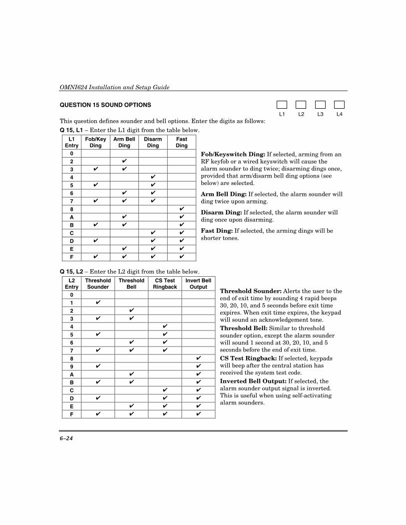
OMNI624 Installation and Setup Guide
6–24
QUESTION 15 SOUND OPTIONS
L1 L2 L3 L4 This question defines sounder and bell options. Enter the digits as follows:
Q 15, L1 – Enter the L1 digit from the table below. L1
Entry Fob/Key
Ding Arm Bell
Ding Disarm
Ding Fast Ding
0
2 ✔
3 ✔ ✔
4 ✔
5 ✔ ✔
6 ✔ ✔
7 ✔ ✔ ✔
8 ✔
A ✔ ✔
B ✔ ✔ ✔
C ✔ ✔
D ✔ ✔ ✔
E ✔ ✔ ✔
F ✔ ✔ ✔ ✔
Fob/Keyswitch Ding: If selected, arming from an RF keyfob or a wired keyswitch will cause the alarm sounder to ding twice; disarming dings once, provided that arm/disarm bell ding options (see below) are selected.
Arm Bell Ding: If selected, the alarm sounder will ding twice upon arming.
Disarm Ding: If selected, the alarm sounder will ding once upon disarming.
Fast Ding: If selected, the arming dings will be shorter tones.
Q 15, L2 – Enter the L2 digit from the table below. L2
Entry Threshold Sounder
Threshold Bell
CS Test Ringback
Invert Bell Output
0
1 ✔
2 ✔
3 ✔ ✔
4 ✔
5 ✔ ✔
6 ✔ ✔
7 ✔ ✔ ✔
8 ✔
9 ✔ ✔
A ✔ ✔
B ✔ ✔ ✔
C ✔ ✔
D ✔ ✔ ✔
E ✔ ✔ ✔
F ✔ ✔ ✔ ✔
Threshold Sounder: Alerts the user to the end of exit time by sounding 4 rapid beeps 30, 20, 10, and 5 seconds before exit time expires. When exit time expires, the keypad will sound an acknowledgement tone. Threshold Bell: Similar to threshold sounder option, except the alarm sounder will sound 1 second at 30, 20, 10, and 5 seconds before the end of exit time. CS Test Ringback: If selected, keypads will beep after the central station has received the system test code. Inverted Bell Output: If selected, the alarm sounder output signal is inverted. This is useful when using self-activating alarm sounders.
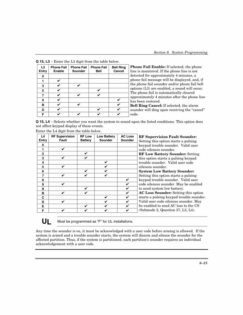
Section 6. System Programming
6–25
Q 15, L3 – Enter the L3 digit from the table below.
L3 Entry
Phone Fail Enable
Phone Fail Sounder
Phone Fail Bell
Bell Ring Cancel
0
1 ✔
3 ✔ ✔
5 ✔ ✔
7 ✔ ✔ ✔
9 ✔ ✔
B ✔ ✔ ✔
D ✔ ✔ ✔
F ✔ ✔ ✔ ✔
Phone Fail Enable: If selected, the phone line is monitored. If the phone line is not detected for approximately 4 minutes, a phone fail message will be displayed, and, if the phone fail sounder and/or phone fail bell options (L3) are enabled, a sound will occur. The phone fail is automatically cleared approximately 4 minutes after the phone line has been restored. Bell Ring Cancel: If selected, the alarm sounder will ding upon receiving the “cancel” code.
Q 15, L4 – Selects whether you want the system to sound upon the listed conditions. This option does not affect keypad display of these events. Enter the L4 digit from the table below.
L4 Entry
RF Supervision Fault
RF Low Battery
Low Battery Sounder
AC Loss Sounder
0
1 ✔
2 ✔
3 ✔ ✔
4 ✔
5 ✔ ✔
6 ✔ ✔
7 ✔ ✔ ✔
8 ✔
9 ✔ ✔
A ✔ ✔
B ✔ ✔ ✔
C ✔ ✔
D ✔ ✔ ✔
E ✔ ✔ ✔
F ✔ ✔ ✔ ✔
RF Supervision Fault Sounder: Setting this option starts a pulsing keypad trouble sounder. Valid user code silences sounder. RF Low Battery Sounder: Setting this option starts a pulsing keypad trouble sounder. Valid user code silences sounder. System Low Battery Sounder: Setting this option starts a pulsing keypad trouble sounder. Valid user code silences sounder. May be enabled to send system low battery. AC Loss Sounder: Setting this option starts a pulsing keypad trouble sounder. Valid user code silences sounder. May be enabled to send AC loss to the CS (Submode 2, Question 37, L3, L4).
UL Must be programmed as “F” for UL installations.
Any time the sounder is on, it must be acknowledged with a user code before arming is allowed. If the system is armed and a trouble sounder starts, the system will disarm and silence the sounder for the affected partition. Thus, if the system is partitioned, each partition’s sounder requires an individual acknowledgement with a user code.

OMNI624 Installation and Setup Guide
6–26
QUESTION 16 DISPLAY OPTIONS
L1 L2 L3 L4 This question defines display options. Enter the digits as follows:
Q 16, L1 – Enter the L1 digit from the table below. L1
Entry Armed Bypass
Display Display Fault
On Entry No AC Loss
Display Manual
Bypass Limit 30
1 ✔
2 ✔
3 ✔ ✔
4 ✔
5 ✔ ✔
6 ✔ ✔
7 ✔ ✔ ✔
8 ✔
9 ✔ ✔
A ✔ ✔
B ✔ ✔ ✔
C ✔ ✔
Armed Bypass Display: If selected, pressing the [BYPASS] key will scroll bypassed zones while the system is armed. Display Fault on Entry: Display faults (open zones) during entry delay time. No AC Loss Display: If selected, the AC loss message will not be displayed on LCD keypads. Manual Bypass Limit 3: If selected, no more than 3 zones can be manually bypassed.
D ✔ ✔ ✔
E ✔ ✔ ✔
F ✔ ✔ ✔ ✔ UL
Do not enable No AC Loss Display (must display AC loss) for UL installations.
Q 16, L2 – Enter the L2 digit from the table below.
L2 Entry
No Code Set
Time
Daylight Saving
(Summer) Time
Keypad Extinguish
Keyfob Low Bat.
Display0
1 ✔
2 ✔
3 ✔ ✔
4 ✔
5 ✔ ✔
6 ✔ ✔
7 ✔ ✔ ✔
8 ✔
9 ✔ ✔
A ✔ ✔
B ✔ ✔ ✔
C ✔ ✔
D ✔ ✔ ✔
E ✔ ✔ ✔
F ✔ ✔ ✔ ✔
No Code Set Time: If selected, allows Quick Command #3 to set time. Intended for low-security installations. Daylight Saving (Summer) Time: If selected, the system will automatically adjust for daylight saving (summer) time (U.S. standard: First Sunday in April at 2:00 AM, the clock goes ahead 1 hour; last Sunday in October at 2:00 AM, the clock goes back 1 hour to standard time). Keypad Extinguish: If selected, the keypad display and LEDs will turn off after 1 minute of no key presses. Keyfob Low-Battery Display: This option determines whether low-battery messages from keyfobs will be displayed. If selected, display is enabled. Note that even if this display is disabled, keyfob low-battery conditions can be checked by using the #56 Quick Command.

Section 6. System Programming
6–27
Q 16, L3 – This location selects the type of clock displays. Enter the L3 digit from the table below.
Clock Day/Month L3 Entry AM/PM 24hr mm/dd dd/mm
Display Time
Display Clock Fail
0 ✔ ✔
1 ✔ ✔
2 ✔ ✔
3 ✔ ✔
4 ✔ ✔ ✔
5 ✔ ✔ ✔
6 ✔ ✔ ✔
7 ✔ ✔ ✔
8 ✔ ✔ ✔
9 ✔ ✔ ✔
A ✔ ✔ ✔
B ✔ ✔ ✔
C ✔ ✔ ✔ ✔
D ✔ ✔ ✔ ✔
E ✔ ✔ ✔ ✔
F ✔ ✔ ✔ ✔
Clock: Shows time in 24-hour format, 00–23 hours. Otherwise, 1–12 hours with A or P. Day/Month: Time displayed as day, then month (23, Feb. 1990); otherwise, as U.S. standard (Feb. 23, 1999). NOTE: Clock set is always entered as 24-hour time, with order the same (in case LED.) See quick command #3. Display Time: LCD only. Displays time (last six digits) during status scroll on line 2. NOTE: The descriptor should be limited to 10 characters when time is displayed or it will be overwritten by the time. Display Clock Fail: LCD only. If the system goes through a hardware reset (loss of all power or watchdog reset), the clock will not be correct and a message will be displayed indicating this.
Q 16, L4 – Language Select: This location selects the language for the keypad display as follows:
0 = English 3 = French 1 = Italian 4 = Dutch 2 = Spanish 5 = Portuguese
QUESTION 17 LOG OPTIONS N/U
L1 L2 L3 L4
This question defines event log options. Enter the digits as follows:

OMNI624 Installation and Setup Guide
6–28
Q 17, L1 – Enter the L1 digit from the table below.
L1 Entry
Event Log by Part. / All
Enable #53 Log Command
Log Zone Alarms
Log Zone Troubles
0 ✔
1 ✔
2 ✔ ✔
3 ✔ ✔
4 ✔ ✔
5 ✔ ✔
6 ✔ ✔ ✔
7 ✔ ✔ ✔
8 ✔ ✔
9 ✔ ✔
A ✔ ✔ ✔
B ✔ ✔ ✔
C ✔ ✔ ✔
D ✔ ✔ ✔
E ✔ ✔ ✔ ✔
F ✔ ✔ ✔ ✔
By Part. / All: If selected, only the events having occurred in the partition in which the keypad is mapped are displayed. Otherwise, all system events are displayed. Enable #53 Log Command: If selected, users will be able to view the log using the #53 command. Log Zone Alarms/Troubles: If selected, alarms and troubles will be included in the event log.
Q17, L2 – Enter the L2 digit for the desired events to be recorded in event log.
L2 Entry
Log Open
Log Close
Log System Events
Log Key Events
0
1 ✔
2 ✔
3 ✔ ✔
4 ✔
5 ✔ ✔
6 ✔ ✔
7 ✔ ✔ ✔
8 ✔
9 ✔ ✔
A ✔ ✔
B ✔ ✔ ✔
C ✔ ✔
D ✔ ✔ ✔
E ✔ ✔ ✔
F ✔ ✔ ✔ ✔

Section 6. System Programming
6–29
Q17, L3 – Enter the L3 digit for the desired events to be recorded in event log
L3 Entry Log RF Battery Log RF Supervision Log Tamper Log Bypass 0 1 ✔
2 ✔
3 ✔ ✔
4 ✔
5 ✔ ✔
6 ✔ ✔
7 ✔ ✔ ✔
8 ✔
9 ✔ ✔
A ✔ ✔
B ✔ ✔ ✔
C ✔ ✔
D ✔ ✔ ✔
E ✔ ✔ ✔
F ✔ ✔ ✔ ✔
QUESTION 18 BELL TIMEOUT/AC DELAY/RING COUNT
L1 L2 L3 L4 Burg bell Fire bell AC dial Ring timeout timeout delay count
Q 18, L1/L2 – Burglary Bell/Fire Bell Timeout
Enter the L1 and L2 digits for the desired burglary and fire bell/siren timeouts, respectively, from the table below.
Entry BURGLARY &
FIRE BELL TIMEOUTS Entry BURGLARY &
FIRE BELL TIMEOUTS
1 3 minutes 9 27 minutes
2 6 minutes A 30 minutes
3 9 minutes B 33 minutes
4 12 minutes C 36 minutes
5 15 minutes D 39 minutes
6 18 minutes E 42 minutes
7 21 minutes F Infinite
8 24 minutes
UL Must be programmed as “2” for UL installations.
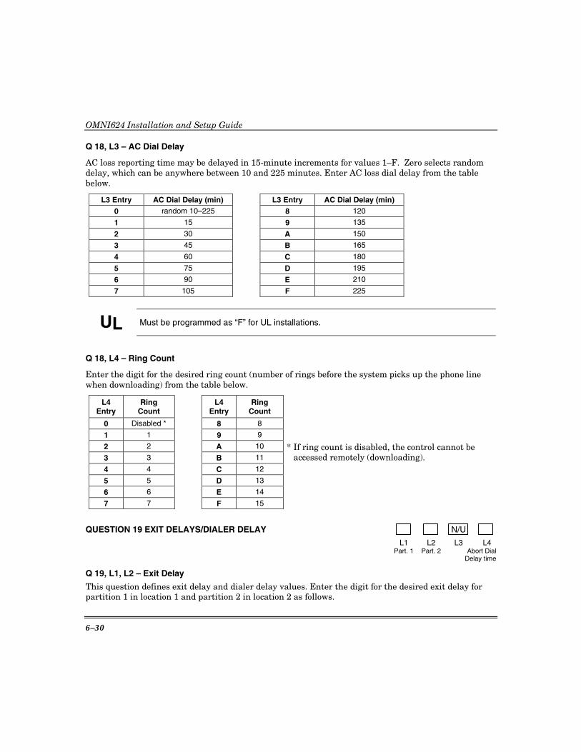
OMNI624 Installation and Setup Guide
6–30
Q 18, L3 – AC Dial Delay
AC loss reporting time may be delayed in 15-minute increments for values 1–F. Zero selects random delay, which can be anywhere between 10 and 225 minutes. Enter AC loss dial delay from the table below.
L3 Entry AC Dial Delay (min) L3 Entry AC Dial Delay (min)
0 random 10–225 8 120
1 15 9 135
2 30 A 150
3 45 B 165
4 60 C 180
5 75 D 195
6 90 E 210
7 105 F 225
UL Must be programmed as “F” for UL installations.
Q 18, L4 – Ring Count
Enter the digit for the desired ring count (number of rings before the system picks up the phone line when downloading) from the table below.
L4 Entry
Ring Count
L4 Entry
Ring Count
0 Disabled * 8 8
1 1 9 9
2 2 A 10
3 3 B 11
4 4 C 12
5 5 D 13
6 6 E 14
7 7 F 15
* If ring count is disabled, the control cannot be accessed remotely (downloading).
QUESTION 19 EXIT DELAYS/DIALER DELAY N/U
L1 L2 L3 L4 Part. 1 Part. 2 Abort Dial Delay time
Q 19, L1, L2 – Exit Delay
This question defines exit delay and dialer delay values. Enter the digit for the desired exit delay for partition 1 in location 1 and partition 2 in location 2 as follows.

Section 6. System Programming
6–31
L1-L2 Entry
Exit Timeouts
L1-L2 Entry
Exit Timeouts
0 4 MINUTES, 30 SECONDS 8 1 MINUTE, 20 SECONDS 1 10 SECONDS 9 1 MINUTE, 30 SECONDS 2 20 SECONDS A 1 MINUTE, 40 SECONDS 3 30 SECONDS B 1 MINUTE, 50 SECONDS 4 40 SECONDS C 2 MINUTES 5 50 SECONDS D 2 MINUTES, 10 SECONDS 6 1 MINUTE E 2 MINUTES, 20 SECONDS 7 1 MINUTE, 10 SECONDS
F 2 MINUTES, 30 SECONDS
NOTE: Entry delay time-outs are selected for each partition in questions 20–21.
UL Must be programmed as “5” for UL installations.
Q 19, L4 – Dialer Delay
Enter the L4 digit for the desired dialer delay from the following table. L4
Entry Dialer Delay (Seconds)
L4 Entry
Dialer Delay (Seconds)
0 15 8 90 1 20 9 105 2 25 A 120 3 30 B 150 4 40 C 180
NOTE: Dialer Delay is system-wide. It is not partition specific.
5 50 D 210 6 60 E 240 7 75 F 255
UL Must be programmed as “0” for UL installations.
Q 20/21 ENTRY DELAYS 1 and 2 N/U N/U
L1 L2 L3 L4 Part. 1 Part. 2
These questions define entry delays 1 and 2 for each partition. Location 1 is for partition 1 and Location 2 is for partition 2 in each question. Enter the digits from the following table.
L1-L4 Entry
Entry Delay Seconds
L1-L4 Entry
Entry Delay Seconds
0 1 8 75 1 5 9 90 2 10 A 105 3 15 B 120 4 20 C 150
UL Must be programmed as “6” for UL installations.
5 30 D 180 6 45 E 210 7 60 F 240
Q 20 – ENTRY DELAY 1 Q 21 – ENTRY DELAY 2
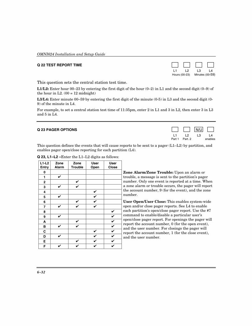
OMNI624 Installation and Setup Guide
6–32
Q 22 TEST REPORT TIME
L1 L2 L3 L4 Hours (00-23) Minutes (00-59)
This question sets the central station test time. L1/L2: Enter hour 00–23 by entering the first digit of the hour (0–2) in L1 and the second digit (0–9) of the hour in L2. (00 = 12 midnight)
L3/L4: Enter minute 00–59 by entering the first digit of the minute (0-5) in L3 and the second digit (0-9) of the minute in L4.
For example, to set a central station test time of 11:35pm, enter 2 in L1 and 3 in L2, then enter 3 in L3 and 5 in L4.
Q 23 PAGER OPTIONS N/U
L1 L2 L3 L4 Part 1 Part. 2 enables
This question defines the events that will cause reports to be sent to a pager (L1–L2) by partition, and enables pager open/close reporting for each partition (L4).
Q 23, L1–L2 –Enter the L1–L2 digits as follows:
L1-L2 Entry
Zone Alarm
Zone Trouble
User Open
User Close
0
1 ✔
2 ✔
3 ✔ ✔
4 ✔
5 ✔ ✔
6 ✔ ✔
7 ✔ ✔ ✔
8 ✔
9 ✔ ✔
A ✔ ✔
B ✔ ✔ ✔
C ✔ ✔
D ✔ ✔ ✔
E ✔ ✔ ✔
F ✔ ✔ ✔ ✔
Zone Alarm/Zone Trouble: Upon an alarm or trouble, a message is sent to the partition’s pager number. Only one event is reported at a time. When a zone alarm or trouble occurs, the pager will report the account number, 9 (for the event), and the zone number.
User Open/User Close: This enables system-wide open and/or close pager reports. See L4 to enable each partition’s open/close pager report. Use the #7 command to enable/disable a particular user’s open/close pager report. For openings the pager will report the account number, 0 (for the open event), and the user number. For closings the pager will report the account number, 1 (for the close event), and the user number.
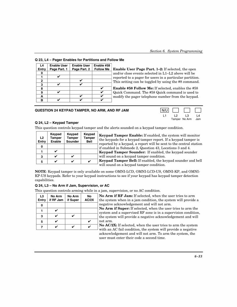
Section 6. System Programming
6–33
Q 23, L4 – Pager Enables for Partitions and Follow Me
L4 Entry
Enable User Page Part. 1
Enable User Page Part. 2
Enable #58 Follow Me
0
1 ✔
2 ✔
3 ✔ ✔
8 ✔
9 ✔ ✔
A ✔ ✔
B ✔ ✔ ✔
Enable User Page Part. 1–2: If selected, the open and/or close events selected in L1–L2 above will be reported to a pager for users in a particular partition. This setting can be toggled by using the #8 command.
Enable #58 Follow Me: If selected, enables the #58 Quick Command. The #58 Quick command is used to modify the pager telephone number from the keypad.
QUESTION 24 KEYPAD TAMPER, NO ARM, AND RF JAM N/U
L1 L2 L3 L4 Tamper No Arm Jam
Q 24, L2 – Keypad Tamper This question controls keypad tamper and the alerts sounded on a keypad tamper condition.
L2 Entry
Keypad Tamper Enable
Keypad Tamper Sounder
Keypad Tamper
Bell
0
1 ✔
3 ✔ ✔
5 ✔ ✔ ✔
Keypad Tamper Enable: If enabled, the system will monitor the keypads for a keypad tamper report. If a keypad tamper is reported by a keypad, a report will be sent to the central stationif enabled in Submode 2, Question 43, Locations 3 and 4. Keypad Tamper Sounder: If enabled, the keypad sounder will sound on a keypad tamper condition. Keypad Tamper Bell: If enabled, the keypad sounder and bell will sound on a keypad tamper condition.
NOTE: Keypad tamper is only available on some OMNI-LCD, OMNI-LCD-US, OMNI-KP, and OMNI-KP-US keypads. Refer to your keypad instructions to see if your keypad has keypad tamper detection capabilities.
Q 24, L3 – No Arm if Jam, Supervision, or AC This question controls arming while in a jam, supervision, or no AC condition.
L3 Entry
No Arm if RF Jam
No Arm if Super
No AC/2X
0
1 ✔
3 ✔ ✔
5 ✔ ✔
7 ✔ ✔ ✔
No Arm if RF Jam: If selected, when the user tries to arm the system when in a jam condition, the system will provide a negative acknowledgement and will not arm. No Arm if Super: If selected, when the user tries to arm the system and a supervised RF zone is in a supervision condition, the system will provide a negative acknowledgement and will not arm. No AC/2X: If selected, when the user tries to arm the system with an AC fail condition, the system will provide a negative acknowledgement and will not arm. To arm the system, the user must enter their code a second time.

OMNI624 Installation and Setup Guide
6–34
Q 24, L4 – Jam Enable, Jam Type, Jam Detection Action This question defines if the system should detect a jam signal from the RF receiver, and if detected, determines the type of jamming to be recognized and the action to be performed (sounder or bell). RF Jamming has not been evaluated by UL. NOTE: RF Jamming detection will only function if the system uses a ZR402EU or OMNI-RF Receiver that has jam output capability.
Jam Type Jam Detection Action L4 Entry
Jam Enable US Euro Silent Sounder Bell
0
1 ✔ ✔ ✔
3 ✔ ✔ ✔
5 ✔ ✔ ✔
7 ✔ ✔ ✔
9 ✔ ✔ ✔
B ✔ ✔ ✔
D ✔ ✔ ✔ ✔
F ✔ ✔ ✔ ✔
Jam Enable: The system will monitor the Jam signal from the receiver and when received, check the jam signal for the criteria set in the Jam Type definition. When a valid jam signal is detected, a message is displayed on the keypad. This keypad message can be cleared by entering a user code if the jamming condition has ceased. Jam Type: The jam type defines the criteria that the jam signal must meet to be considered a valid jamming signal. The types are as follows:
EUROPEAN (Euro): If a jam signal is detected for a total of 30 seconds in a 60-second period (not necessarily in one continuous stretch), then qualify it as a jam condition and report it. DOMESTIC (US): If a jam signal is detected for a period of 20 consecutive seconds, then qualify it as a jam condition and report it.
Jam Detection Action: The actions that can be taken by the system when a valid jam signal is detected is to report the jam, report the jam and sound the keypad sounder or alarm sounder, or report the jam and sound both the keypad sounder and alarm sounder. The report code is programmed in Submode 2, Question 39, L3 and L4.
Q 25 NOT USED
QUESTION 26 SOFT KEY FUNCTIONS (1 & 3/7 & 9)
L1 L2 L3 L4 1 & 3 Keys 7 & 9 Keys
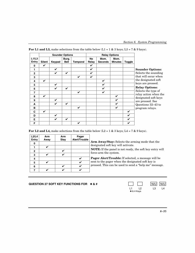
Section 6. System Programming
6–35
For L1 and L3, make selections from the table below (L1 = 1 & 3 keys; L3 = 7 & 9 keys).
Sounder Options Relay Options L1/L3 Entry Silent Keypad
Burg. Bell Temporal
No Relay
Mom. Seconds
Mom. Minutes Toggle
0 ✔ ✔
1 ✔ ✔
2 ✔ ✔ ✔
3 ✔ ✔
4 ✔ ✔
5 ✔ ✔
6 ✔ ✔ ✔
7 ✔ ✔
8 ✔ ✔
9 ✔ ✔
A ✔ ✔ ✔
B ✔ ✔
C ✔ ✔
D ✔ ✔
E ✔ ✔ ✔
F ✔ ✔
Sounder Options: Selects the sounding that will occur when the designated soft keys are pressed. Relay Options: Selects the type of relay action when the designated soft keys are pressed. See Questions 32–43 to program relays.
For L2 and L4, make selections from the table below (L2 = 1 & 3 keys; L4 = 7 & 9 keys).
L2/L4 Entry
Arm Away
Arm Stay
Pager Alert/Trouble
0
1 ✔
2 ✔
3 ✔ ✔
4 ✔
5 ✔ ✔
6 ✔ ✔
7 ✔ ✔ ✔
Arm Away/Stay: Selects the arming mode that the designated soft key will activate. NOTE: If the panel is not ready, the soft key entry will force-arm the system.
Pager Alert/Trouble: If selected, a message will be sent to the pager when the designated soft key is pressed. This can be used to send a “help me” message.
QUESTION 27 SOFT KEY FUNCTIONS FOR ✱ & # N/U N/U
L1 L2 L3 L4 ✱ & # Keys

OMNI624 Installation and Setup Guide
6–36
For L1, make selections from the table below.
Sounder Options Relay Options L1/L3 Entry Silent Keypad
Burg. Bell Temporal
No Relay
Mom. Seconds
Mom. Minutes Toggle
0 ✔ ✔
1 ✔ ✔
2 ✔ ✔ ✔
3 ✔ ✔
4 ✔ ✔
5 ✔ ✔
6 ✔ ✔ ✔
7 ✔ ✔
8 ✔ ✔
9 ✔ ✔
A ✔ ✔ ✔
B ✔ ✔
C ✔ ✔
D ✔ ✔
E ✔ ✔ ✔
F ✔ ✔
For L2, make a selection from the table below.
L2 Entry
Arm Away
Arm Stay
Pager Alert/Trouble
0
1 ✔
2 ✔
3 ✔ ✔
4 ✔
5 ✔ ✔
6 ✔ ✔
7 ✔ ✔ ✔
Arm Away/Stay: Selects the arming mode that the designated soft key will activate. NOTE: If the panel is not ready, the soft key entry will force-arm the system.
Pager Alert/Trouble: If selected, a message will be sent to the pager when the designated soft key is pressed. This can be used to send a “help me” message.
QUESTION 28 AUTO-ARM ENABLES N/U
L1 L2 L3 L4 Q 28, L1–L2 Part 1 Part. 2 Up/About
This question enables auto-arming. See Question 29 (partition 1) and 30 (partition 2) for setting the auto-arm times for each partition. Enter the L1–L2 digits as follows:
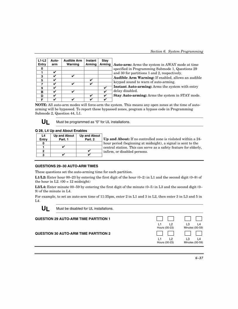
Section 6. System Programming
6–37
L1-L2 Entry
Auto-arm
Audible Arm Warning
Instant Arming
Stay Arming
0
1 ✔
3 ✔ ✔
5 ✔ ✔
7 ✔ ✔ ✔
9 ✔ ✔
B ✔ ✔ ✔
D ✔ ✔ ✔
F ✔ ✔ ✔ ✔
Auto-arm: Arms the system in AWAY mode at time specified in Programming Submode 1, Questions 29 and 30 for partitions 1 and 2, respectively. Audible Arm Warning: If enabled, allows an audible keypad sound to warn of auto-arming. Instant Auto-arming: Arms the system with entry delay disabled. Stay Auto-arming: Arms the system in STAY mode.
NOTE: All auto-arm modes will force-arm the system. This means any open zones at the time of auto-arming will be bypassed. To report these bypassed zones, program a bypass code in Programming Submode 2, Question 44, L1.
UL Must be programmed as “0” for UL installations.
Q 28, L4 Up and About Enables L4
Entry Up and About
Part. 1 Up and About
Part. 2 0
1 ✔
2 ✔
3 ✔ ✔
Up and About: If no controlled zone is violated within a 24-hour period (beginning at midnight), a signal is sent to the central station. This can serve as a safety feature for elderly, infirm, or disabled persons.
QUESTIONS 29–30 AUTO-ARM TIMES
These questions set the auto-arming time for each partition.
L1/L2: Enter hour 00–23 by entering the first digit of the hour (0–2) in L1 and the second digit (0–9) of the hour in L2. (00 = 12 midnight)
L3/L4: Enter minute 00–59 by entering the first digit of the minute (0–5) in L3 and the second digit (0–9) of the minute in L4.
For example, to set an auto-arm time of 11:35pm, enter 2 in L1 and 3 in L2, then enter 3 in L3 and 5 in L4.
UL Must be disabled for UL installations.
QUESTION 29 AUTO-ARM TIME PARTITION 1 L1 L2 L3 L4 Hours (00-23) Minutes (00-59)
QUESTION 30 AUTO-ARM TIME PARTITION 2 L1 L2 L3 L4 Hours (00-23) Minutes (00-59)
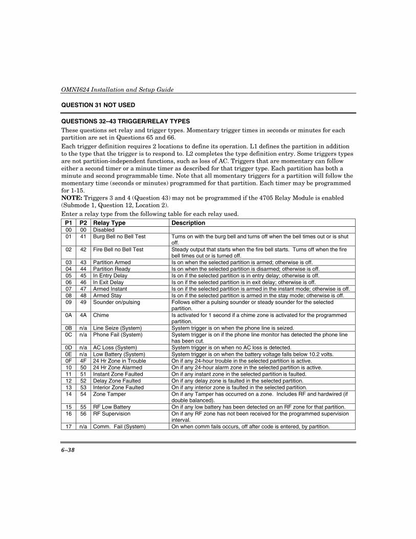
OMNI624 Installation and Setup Guide
6–38
QUESTION 31 NOT USED
QUESTIONS 32–43 TRIGGER/RELAY TYPES These questions set relay and trigger types. Momentary trigger times in seconds or minutes for each partition are set in Questions 65 and 66. Each trigger definition requires 2 locations to define its operation. L1 defines the partition in addition to the type that the trigger is to respond to. L2 completes the type definition entry. Some triggers types are not partition-independent functions, such as loss of AC. Triggers that are momentary can follow either a second timer or a minute timer as described for that trigger type. Each partition has both a minute and second programmable time. Note that all momentary triggers for a partition will follow the momentary time (seconds or minutes) programmed for that partition. Each timer may be programmed for 1-15. NOTE: Triggers 3 and 4 (Question 43) may not be programmed if the 4705 Relay Module is enabled (Submode 1, Question 12, Location 2). Enter a relay type from the following table for each relay used.
P1 P2 Relay Type Description 00 00 Disabled 01 41 Burg Bell no Bell Test Turns on with the burg bell and turns off when the bell times out or is shut
off. 02 42 Fire Bell no Bell Test Steady output that starts when the fire bell starts. Turns off when the fire
bell times out or is turned off. 03 43 Partition Armed Is on when the selected partition is armed; otherwise is off. 04 44 Partition Ready Is on when the selected partition is disarmed; otherwise is off. 05 45 In Entry Delay Is on if the selected partition is in entry delay; otherwise is off. 06 46 In Exit Delay Is on if the selected partition is in exit delay; otherwise is off. 07 47 Armed Instant Is on if the selected partition is armed in the instant mode; otherwise is off. 08 48 Armed Stay Is on if the selected partition is armed in the stay mode; otherwise is off. 09 49 Sounder on/pulsing Follows either a pulsing sounder or steady sounder for the selected
partition. 0A 4A Chime Is activated for 1 second if a chime zone is activated for the programmed
partition. 0B n/a Line Seize (System) System trigger is on when the phone line is seized. 0C n/a Phone Fail (System) System trigger is on if the phone line monitor has detected the phone line
has been cut. 0D n/a AC Loss (System) System trigger is on when no AC loss is detected. 0E n/a Low Battery (System) System trigger is on when the battery voltage falls below 10.2 volts. 0F 4F 24 Hr Zone in Trouble On if any 24-hour trouble in the selected partition is active. 10 50 24 Hr Zone Alarmed On if any 24-hour alarm zone in the selected partition is active. 11 51 Instant Zone Faulted On if any instant zone in the selected partition is faulted. 12 52 Delay Zone Faulted On if any delay zone is faulted in the selected partition. 13 53 Interior Zone Faulted On if any interior zone is faulted in the selected partition. 14 54 Zone Tamper On if any Tamper has occurred on a zone. Includes RF and hardwired (if
double balanced). 15 55 RF Low Battery On if any low battery has been detected on an RF zone for that partition. 16 56 RF Supervision On if any RF zone has not been received for the programmed supervision
interval. 17 n/a Comm. Fail (System) On when comm fails occurs, off after code is entered, by partition.
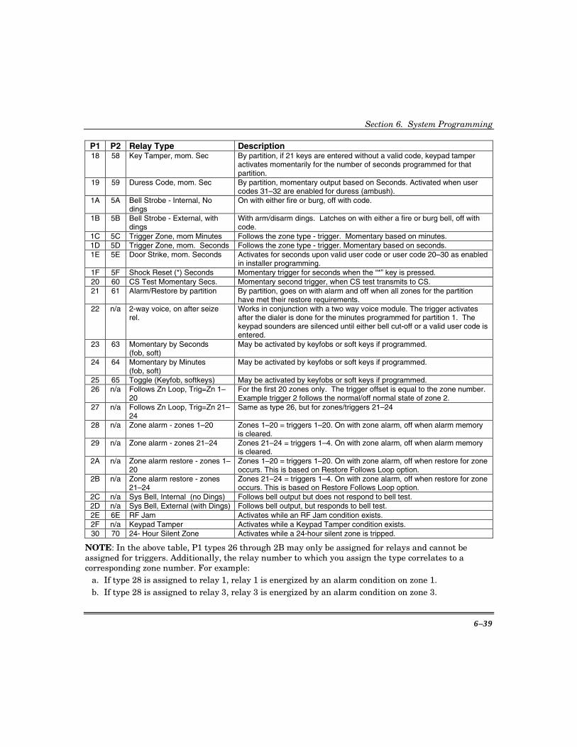
Section 6. System Programming
6–39
P1 P2 Relay Type Description 18 58 Key Tamper, mom. Sec By partition, if 21 keys are entered without a valid code, keypad tamper
activates momentarily for the number of seconds programmed for that partition.
19 59 Duress Code, mom. Sec By partition, momentary output based on Seconds. Activated when user codes 31–32 are enabled for duress (ambush).
1A 5A Bell Strobe - Internal, No dings
On with either fire or burg, off with code.
1B 5B Bell Strobe - External, with dings
With arm/disarm dings. Latches on with either a fire or burg bell, off with code.
1C 5C Trigger Zone, mom Minutes Follows the zone type - trigger. Momentary based on minutes. 1D 5D Trigger Zone, mom. Seconds Follows the zone type - trigger. Momentary based on seconds. 1E 5E Door Strike, mom. Seconds Activates for seconds upon valid user code or user code 20–30 as enabled
in installer programming. 1F 5F Shock Reset (*) Seconds Momentary trigger for seconds when the “*” key is pressed. 20 60 CS Test Momentary Secs. Momentary second trigger, when CS test transmits to CS. 21 61 Alarm/Restore by partition By partition, goes on with alarm and off when all zones for the partition
have met their restore requirements. 22 n/a 2-way voice, on after seize
rel. Works in conjunction with a two way voice module. The trigger activates after the dialer is done for the minutes programmed for partition 1. The keypad sounders are silenced until either bell cut-off or a valid user code is entered.
23 63 Momentary by Seconds (fob, soft)
May be activated by keyfobs or soft keys if programmed.
24 64 Momentary by Minutes (fob, soft)
May be activated by keyfobs or soft keys if programmed.
25 65 Toggle (Keyfob, softkeys) May be activated by keyfobs or soft keys if programmed. 26 n/a Follows Zn Loop, Trig=Zn 1–
20 For the first 20 zones only. The trigger offset is equal to the zone number. Example trigger 2 follows the normal/off normal state of zone 2.
27 n/a Follows Zn Loop, Trig=Zn 21–24
Same as type 26, but for zones/triggers 21–24
28 n/a Zone alarm - zones 1–20 Zones 1–20 = triggers 1–20. On with zone alarm, off when alarm memory is cleared.
29 n/a Zone alarm - zones 21–24 Zones 21–24 = triggers 1–4. On with zone alarm, off when alarm memory is cleared.
2A n/a Zone alarm restore - zones 1–20
Zones 1–20 = triggers 1–20. On with zone alarm, off when restore for zone occurs. This is based on Restore Follows Loop option.
2B n/a Zone alarm restore - zones 21–24
Zones 21–24 = triggers 1–4. On with zone alarm, off when restore for zone occurs. This is based on Restore Follows Loop option.
2C n/a Sys Bell, Internal (no Dings) Follows bell output but does not respond to bell test. 2D n/a Sys Bell, External (with Dings) Follows bell output, but responds to bell test. 2E 6E RF Jam Activates while an RF Jam condition exists. 2F n/a Keypad Tamper Activates while a Keypad Tamper condition exists. 30 70 24- Hour Silent Zone Activates while a 24-hour silent zone is tripped.
NOTE: In the above table, P1 types 26 through 2B may only be assigned for relays and cannot be assigned for triggers. Additionally, the relay number to which you assign the type correlates to a corresponding zone number. For example:
a. If type 28 is assigned to relay 1, relay 1 is energized by an alarm condition on zone 1. b. If type 28 is assigned to relay 3, relay 3 is energized by an alarm condition on zone 3.
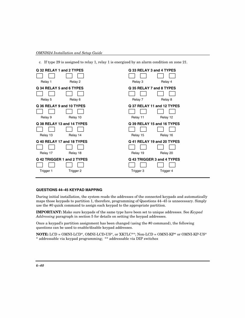
OMNI624 Installation and Setup Guide
6–40
c. If type 29 is assigned to relay 1, relay 1 is energized by an alarm condition on zone 21.
Q 32 RELAY 1 and 2 TYPES Q 33 RELAY 3 and 4 TYPES
Relay 1 Relay 2 Relay 3 Relay 4
Q 34 RELAY 5 and 6 TYPES Q 35 RELAY 7 and 8 TYPES
Relay 5 Relay 6 Relay 7 Relay 8
Q 36 RELAY 9 and 10 TYPES Q 37 RELAY 11 and 12 TYPES
Relay 9 Relay 10 Relay 11 Relay 12
Q 38 RELAY 13 and 14 TYPES Q 39 RELAY 15 and 16 TYPES
Relay 13 Relay 14 Relay 15 Relay 16
Q 40 RELAY 17 and 18 TYPES Q 41 RELAY 19 and 20 TYPES
Relay 17 Relay 18 Relay 19 Relay 20
Q 42 TRIGGER 1 and 2 TYPES Q 43 TRIGGER 3 and 4 TYPES
Trigger 1 Trigger 2 Trigger 3 Trigger 4
QUESTIONS 44–45 KEYPAD MAPPING
During initial installation, the system reads the addresses of the connected keypads and automatically maps those keypads to partition 1, therefore, programming of Questions 44–45 is unnecessary. Simply use the #0 quick command to assign each keypad to the appropriate partition.
IMPORTANT: Make sure keypads of the same type have been set to unique addresses. See Keypad Addressing paragraph in section 5 for details on setting the keypad addresses.
Once a keypad’s partition assignment has been changed (using the #0 command), the following questions can be used to enable/disable keypad addresses.
NOTE: LCD = OMNI-LCD*, OMNI-LCD-US*, or XK7LC**; Non-LCD = OMNI-KP* or OMNI-KP-US* * addressable via keypad programming; ** addressable via DIP switches
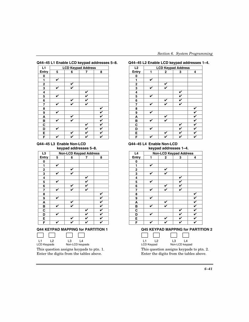
Section 6. System Programming
6–41
Q44–45 L1 Enable LCD keypad addresses 5–8. Q44–45 L2 Enable LCD keypad addresses 1–4. LCD Keypad Address LCD Keypad Address L1
Entry 5 6 7 8 L2
Entry 1 2 3 4 0 0
1 ✔ 1 ✔
2 ✔ 2 ✔
3 ✔ ✔ 3 ✔ ✔
4 ✔ 4 ✔
5 ✔ ✔ 5 ✔ ✔
6 ✔ ✔ 6 ✔ ✔
7 ✔ ✔ ✔ 7 ✔ ✔ ✔
8 ✔ 8 ✔
9 ✔ ✔ 9 ✔ ✔
A ✔ ✔ A ✔ ✔
B ✔ ✔ ✔ B ✔ ✔ ✔
C ✔ ✔ C ✔ ✔
D ✔ ✔ ✔ D ✔ ✔ ✔
E ✔ ✔ ✔ E ✔ ✔ ✔
F ✔ ✔ ✔ ✔
F ✔ ✔ ✔ ✔
Q44–45 L3 Enable Non-LCD Q44–45 L4 Enable Non-LCD keypad addresses 5–8. keypad addresses 1–4.
Non-LCD Keypad Address Non-LCD Keypad Address L3 Entry 5 6 7 8
L4 Entry 1 2 3 4
0 0
1 ✔ 1 ✔
2 ✔ 2 ✔
3 ✔ ✔ 3 ✔ ✔
4 ✔ 4 ✔
5 ✔ ✔ 5 ✔ ✔
6 ✔ ✔ 6 ✔ ✔
7 ✔ ✔ ✔ 7 ✔ ✔ ✔
8 ✔ 8 ✔
9 ✔ ✔ 9 ✔ ✔
A ✔ ✔ A ✔ ✔
B ✔ ✔ ✔ B ✔ ✔ ✔
C ✔ ✔ C ✔ ✔
D ✔ ✔ ✔ D ✔ ✔ ✔
E ✔ ✔ ✔ E ✔ ✔ ✔
F ✔ ✔ ✔ ✔
F ✔ ✔ ✔ ✔
Q44 KEYPAD MAPPING for PARTITION 1 Q45 KEYPAD MAPPING for PARTITION 2
L1 L2 L3 L4 L1 L2 L3 L4 LCD Keypads Non-LCD keypads LCD Keypad Non-LCD keypad
This question assigns keypads to ptn. 1. This question assigns keypads to ptn. 2. Enter the digits from the tables above. Enter the digits from the tables above.

OMNI624 Installation and Setup Guide
6–42
QUESTIONS 46–48 NOT USED
QUESTIONS 49–64 KEYFOB BUTTON FUNCTIONS and USERS The following odd-numbered questions set the RF keyfob button functions. The even-numbered questions assign the partition in which the keyfob functions and the associated users for open/close reporting. See Installer Mode 3, Questions 25–32 to assign the number of buttons used by each keyfob and to store their serial numbers. For odd numbered questions, enter the digits in each location as follows:
L1-L4 Entry Keyfob Function
L1-L4 Entry Keyfob Function
0 Disabled 6 Keypad 7 & 9 1 Disarm 7 Keypad * & # 2 Arm Away 8 Keypad 1 & 3 3 Arm Stay 9 Relay Type 23 (mom. seconds)4 Arm Instant A Relay Type 24 (mom. minutes) 5 Arm Stay/Instant B Relay Type 25 (toggle)
YOU MUSTPROGRAM
THIS BUTTON
LOOP 3
LOOP 1
LOOP 2LOOP 4
5804 Wireless Key
NOTE: If an arming function is assigned to the keyfob and it is used to arm the system when the system is not ready, the system will be force armed.
For even-numbered questions, enter the digits as follows (L1: not used): L2: Enter the partition number (P1=1; P2=2) for arming/disarming for this keyfob. This defines the partition in which the keyfob is located. L3/L4: Enter the user number (01–32) associated with this keyfob. Enter the first digit of the user number in L3 and enter the second digit in L4.
UL Keyfobs have not been evaluated for UL installations.
Q 49 KEYFOB 1 FUNCTIONS Q 50 KEYFOB 1 USER
N/A
L1 L2 L3 L4 L1 L2 L3 L4 Button 1 Button2 Button 3 Button 4 Arm Part. User number
Q 51 KEYFOB 2 FUNCTIONS Q 52 KEYFOB 2 USER
N/A
L1 L2 L3 L4 L1 L2 L3 L4 Button 1 Button2 Button 3 Button 4 Arm Part. User number
Q 53 KEYFOB 3 FUNCTIONS Q 54 KEYFOB 3 USER
N/A
L1 L2 L3 L4 L1 L2 L3 L4 Button 1 Button2 Button 3 Button 4 Arm Part. User number

Section 6. System Programming
6–43
Q 55 KEYFOB 4 FUNCTIONS Q 56 KEYFOB 4 USER
N/A
L1 L2 L3 L4 L1 L2 L3 L4 Button 1 Button2 Button 3 Button 4 Arm Part. User number
Q 57 KEYFOB 5 FUNCTIONS Q 58 KEYFOB 5 USER
N/A
L1 L2 L3 L4 L1 L2 L3 L4 Button 1 Button2 Button 3 Button 4 Arm Part. User number
Q 59 KEYFOB 6 FUNCTIONS Q 60 KEYFOB 6 USER
N/A
L1 L2 L3 L4 L1 L2 L3 L4 Button 1 Button2 Button 3 Button 4 Arm Part. User number
Q 61 KEYFOB 7 FUNCTIONS Q 62 KEYFOB 7 USER
N/A
L1 L2 L3 L4 L1 L2 L3 L4 Button 1 Button2 Button 3 Button 4 Arm Part. User number
Q 63 KEYFOB 8 FUNCTIONS Q 64 KEYFOB 8 USER
N/A
L1 L2 L3 L4 L1 L2 L3 L4 Button 1 Button2 Button 3 Button 4 Arm Part. User number
QUESTIONS 65–66 RELAY/TRIGGER TIME for MOMENTARY OUTPUTS These questions set the relay/trigger time for each partition. The time set applies to all triggers within that partition. From the following table, enter the desired time the relay/triggers should remain activated (for Question 65, the times are in minutes, for Question 66 the times are in seconds):
L1-L2 Entry
RELAY TIME (Q65=min/Q66=sec)
L1-L2 Entry
RELAY TIME (Q65=min/Q66=sec)
L1-L2Entry
RELAY TIME (Q65=min/Q66=sec)
0 same as entering “1” 6 6 C 12 1 1 7 7 D 13 2 2 8 8 E 14 3 3 9 9 F 15 4 4 A 10 5 5 B 11
Q 65 RELAY/TRIGGER TIME MINUTES N/U N/U
L1 L2 L3 L4 Part.1 Part. 2
Q 66 RELAY/TRIGGER TIME SECONDS N/U N/U
L1 L2 L3 L4 Part.1 Part. 2
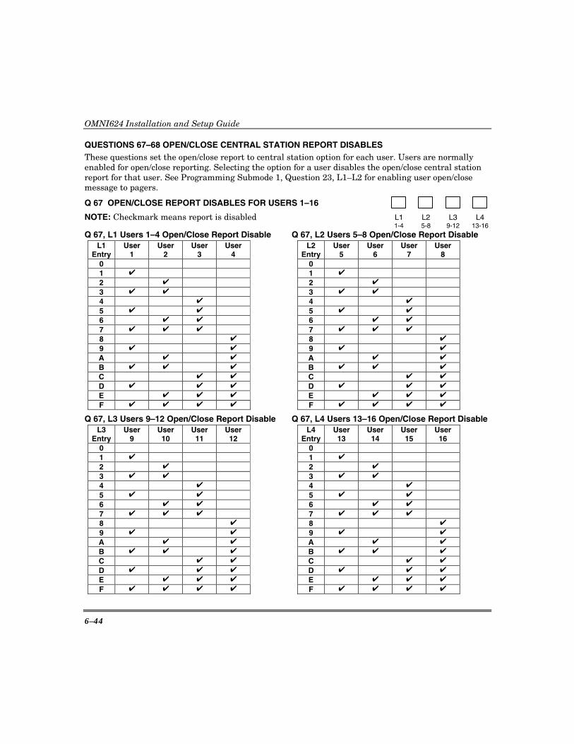
OMNI624 Installation and Setup Guide
6–44
QUESTIONS 67–68 OPEN/CLOSE CENTRAL STATION REPORT DISABLES These questions set the open/close report to central station option for each user. Users are normally enabled for open/close reporting. Selecting the option for a user disables the open/close central station report for that user. See Programming Submode 1, Question 23, L1–L2 for enabling user open/close message to pagers.
Q 67 OPEN/CLOSE REPORT DISABLES FOR USERS 1–16
NOTE: Checkmark means report is disabled L1 L2 L3 L4 1-4 5-8 9-12 13-16
Q 67, L1 Users 1–4 Open/Close Report Disable Q 67, L2 Users 5–8 Open/Close Report Disable L1
Entry User
1 User
2 User
3 User
4 L2
EntryUser
5 User
6 User
7 User
8 0 0
1 ✔ 1 ✔
2 ✔ 2 ✔
3 ✔ ✔ 3 ✔ ✔
4 ✔ 4 ✔
5 ✔ ✔ 5 ✔ ✔
6 ✔ ✔ 6 ✔ ✔
7 ✔ ✔ ✔ 7 ✔ ✔ ✔
8 ✔ 8 ✔
9 ✔ ✔ 9 ✔ ✔
A ✔ ✔ A ✔ ✔
B ✔ ✔ ✔ B ✔ ✔ ✔
C ✔ ✔ C ✔ ✔
D ✔ ✔ ✔ D ✔ ✔ ✔
E ✔ ✔ ✔ E ✔ ✔ ✔
F ✔ ✔ ✔ ✔ F ✔ ✔ ✔ ✔
Q 67, L3 Users 9–12 Open/Close Report Disable Q 67, L4 Users 13–16 Open/Close Report Disable L3
Entry User
9 User10
User 11
User 12
L4 Entry
User13
User14
User 15
User 16
0 0
1 ✔ 1 ✔
2 ✔ 2 ✔
3 ✔ ✔ 3 ✔ ✔
4 ✔ 4 ✔
5 ✔ ✔ 5 ✔ ✔
6 ✔ ✔ 6 ✔ ✔
7 ✔ ✔ ✔ 7 ✔ ✔ ✔
8 ✔ 8 ✔
9 ✔ ✔ 9 ✔ ✔
A ✔ ✔ A ✔ ✔
B ✔ ✔ ✔ B ✔ ✔ ✔
C ✔ ✔ C ✔ ✔
D ✔ ✔ ✔ D ✔ ✔ ✔
E ✔ ✔ ✔ E ✔ ✔ ✔
F ✔ ✔ ✔ ✔ F ✔ ✔ ✔ ✔

Section 6. System Programming
6–45
Q 68 OPEN/CLOSE REPORT DISABLES FOR USERS 17–32
L1 L2 L3 L4 17-20 21-24 25-28 29-32
Q 68, L1 Users 17–20 Open/Close Report Disable Q 68, L2 Users 21–24 Open/Close Report Disable L1
Entry User 17
User18
User 19
User 20
L2 Entry
User21
User22
User 23
User 24
0 0
1 ✔ 1 ✔
2 ✔ 2 ✔
3 ✔ ✔ 3 ✔ ✔
4 ✔ 4 ✔
5 ✔ ✔ 5 ✔ ✔
6 ✔ ✔ 6 ✔ ✔
7 ✔ ✔ ✔ 7 ✔ ✔ ✔
8 ✔ 8 ✔
9 ✔ ✔ 9 ✔ ✔
A ✔ ✔ A ✔ ✔
B ✔ ✔ ✔ B ✔ ✔ ✔
C ✔ ✔ C ✔ ✔
D ✔ ✔ ✔ D ✔ ✔ ✔
E ✔ ✔ ✔ E ✔ ✔ ✔
F ✔ ✔ ✔ ✔ F ✔ ✔ ✔ ✔
Q 68, L3 Users 25–28 Open/Close Report Disable Q 68, L4 Users 29–32 Open/Close Report Disable L3
Entry User 25
User26
User 27
User 28
L4 Entry
User29
User30
User 31
User 32
0 0
1 ✔ 1 ✔
2 ✔ 2 ✔
3 ✔ ✔ 3 ✔ ✔
4 ✔ 4 ✔
5 ✔ ✔ 5 ✔ ✔
6 ✔ ✔ 6 ✔ ✔
7 ✔ ✔ ✔ 7 ✔ ✔ ✔
8 ✔ 8 ✔
9 ✔ ✔ 9 ✔ ✔
A ✔ ✔ A ✔ ✔
B ✔ ✔ ✔ B ✔ ✔ ✔
C ✔ ✔ C ✔ ✔
D ✔ ✔ ✔ D ✔ ✔ ✔
E ✔ ✔ ✔ E ✔ ✔ ✔
F ✔ ✔ ✔ ✔ F ✔ ✔ ✔ ✔
Programming Submode 2: ZONE PROGRAMMING / REPORT CODES Press [✱] + [BYPASS] while in Installer Mode 1, then press [2] to enter Zone Programming submode.
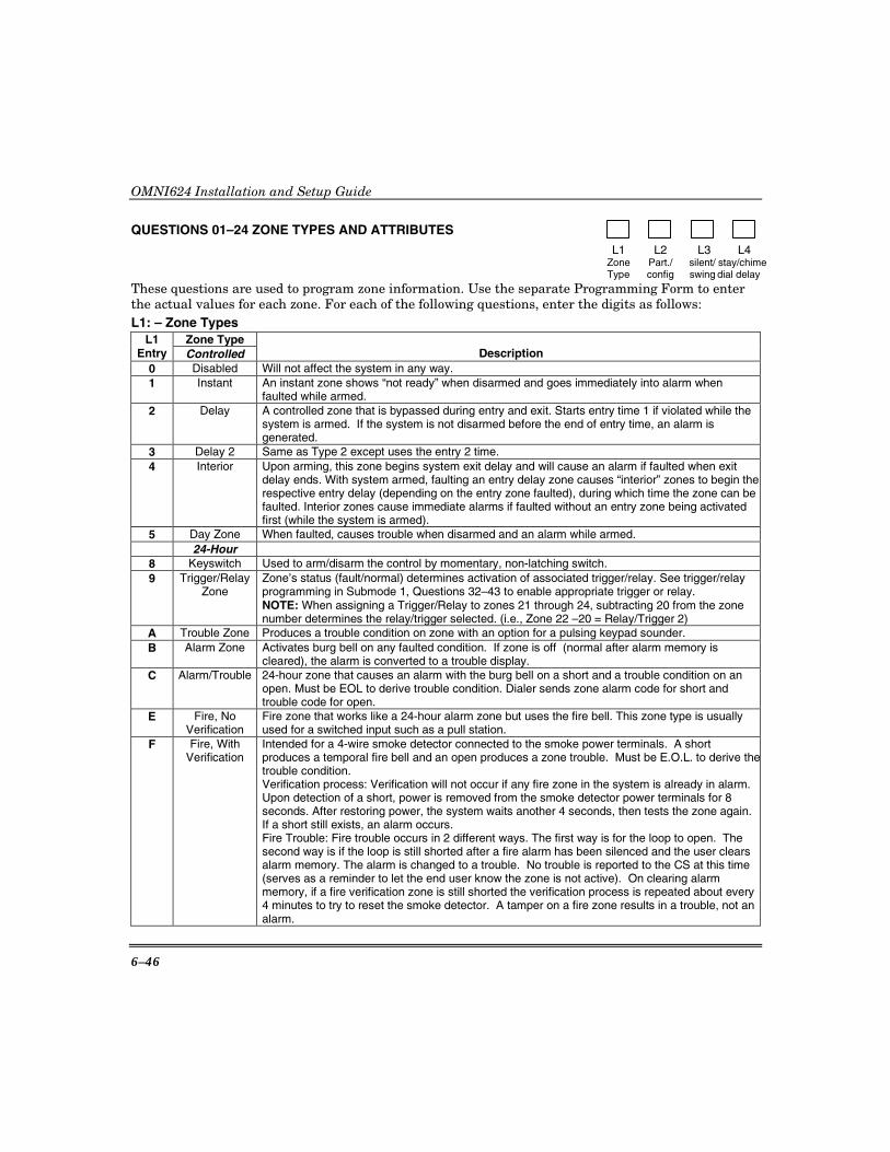
OMNI624 Installation and Setup Guide
6–46
QUESTIONS 01–24 ZONE TYPES AND ATTRIBUTES
L1 L2 L3 L4 Zone Part./ silent/ stay/chime Type config swing dial delay
These questions are used to program zone information. Use the separate Programming Form to enter the actual values for each zone. For each of the following questions, enter the digits as follows: L1: – Zone Types
Zone Type L1 Entry Controlled Description
0 Disabled Will not affect the system in any way. 1 Instant An instant zone shows “not ready” when disarmed and goes immediately into alarm when
faulted while armed. 2 Delay A controlled zone that is bypassed during entry and exit. Starts entry time 1 if violated while the
system is armed. If the system is not disarmed before the end of entry time, an alarm is generated.
3 Delay 2 Same as Type 2 except uses the entry 2 time. 4 Interior Upon arming, this zone begins system exit delay and will cause an alarm if faulted when exit
delay ends. With system armed, faulting an entry delay zone causes “interior” zones to begin the respective entry delay (depending on the entry zone faulted), during which time the zone can be faulted. Interior zones cause immediate alarms if faulted without an entry zone being activated first (while the system is armed).
5 Day Zone When faulted, causes trouble when disarmed and an alarm while armed. 24-Hour
8 Keyswitch Used to arm/disarm the control by momentary, non-latching switch. 9 Trigger/Relay
Zone Zone’s status (fault/normal) determines activation of associated trigger/relay. See trigger/relay programming in Submode 1, Questions 32–43 to enable appropriate trigger or relay. NOTE: When assigning a Trigger/Relay to zones 21 through 24, subtracting 20 from the zone number determines the relay/trigger selected. (i.e., Zone 22 –20 = Relay/Trigger 2)
A Trouble Zone Produces a trouble condition on zone with an option for a pulsing keypad sounder. B Alarm Zone Activates burg bell on any faulted condition. If zone is off (normal after alarm memory is
cleared), the alarm is converted to a trouble display. C Alarm/Trouble 24-hour zone that causes an alarm with the burg bell on a short and a trouble condition on an
open. Must be EOL to derive trouble condition. Dialer sends zone alarm code for short and trouble code for open.
E Fire, No Verification
Fire zone that works like a 24-hour alarm zone but uses the fire bell. This zone type is usually used for a switched input such as a pull station.
F Fire, With Verification
Intended for a 4-wire smoke detector connected to the smoke power terminals. A short produces a temporal fire bell and an open produces a zone trouble. Must be E.O.L. to derive thetrouble condition. Verification process: Verification will not occur if any fire zone in the system is already in alarm. Upon detection of a short, power is removed from the smoke detector power terminals for 8 seconds. After restoring power, the system waits another 4 seconds, then tests the zone again. If a short still exists, an alarm occurs. Fire Trouble: Fire trouble occurs in 2 different ways. The first way is for the loop to open. The second way is if the loop is still shorted after a fire alarm has been silenced and the user clears alarm memory. The alarm is changed to a trouble. No trouble is reported to the CS at this time (serves as a reminder to let the end user know the zone is not active). On clearing alarm memory, if a fire verification zone is still shorted the verification process is repeated about every 4 minutes to try to reset the smoke detector. A tamper on a fire zone results in a trouble, not an alarm.
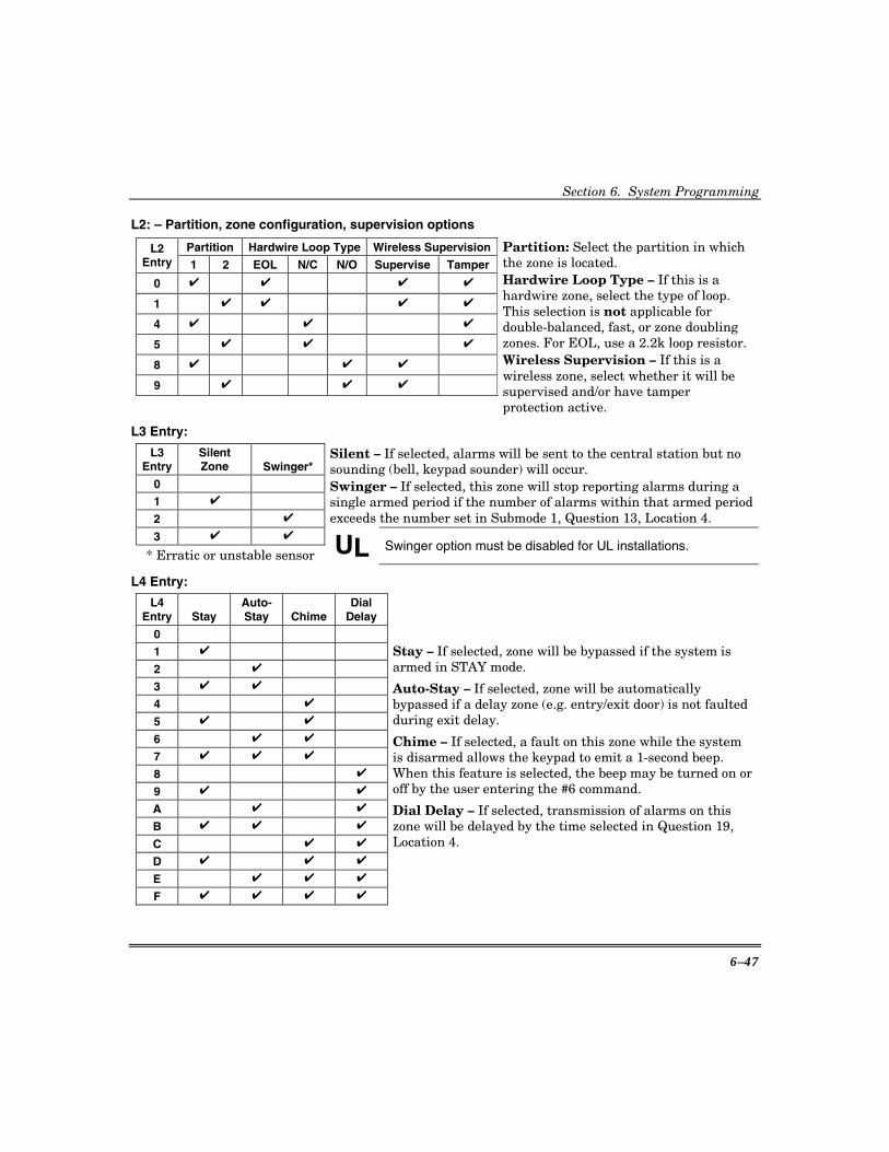
Section 6. System Programming
6–47
L2: – Partition, zone configuration, supervision options
Partition Hardwire Loop Type Wireless Supervision L2 Entry 1 2 EOL N/C N/O Supervise Tamper
0 ✔ ✔ ✔ ✔
1 ✔ ✔ ✔ ✔
4 ✔ ✔ ✔
5 ✔ ✔ ✔
8 ✔ ✔ ✔
9 ✔ ✔ ✔
Partition: Select the partition in which the zone is located. Hardwire Loop Type – If this is a hardwire zone, select the type of loop. This selection is not applicable for double-balanced, fast, or zone doubling zones. For EOL, use a 2.2k loop resistor. Wireless Supervision – If this is a wireless zone, select whether it will be supervised and/or have tamper protection active.
L3 Entry:
L3 Entry
Silent Zone Swinger*
0
1 ✔
2 ✔
Silent – If selected, alarms will be sent to the central station but no sounding (bell, keypad sounder) will occur. Swinger – If selected, this zone will stop reporting alarms during a single armed period if the number of alarms within that armed period exceeds the number set in Submode 1, Question 13, Location 4.
3 ✔ ✔
* Erratic or unstable sensor UL Swinger option must be disabled for UL installations.
L4 Entry:
L4 Entry Stay
Auto-Stay Chime
Dial Delay
0
1 ✔
2 ✔
3 ✔ ✔
4 ✔
5 ✔ ✔
6 ✔ ✔
7 ✔ ✔ ✔
8 ✔
9 ✔ ✔
A ✔ ✔
B ✔ ✔ ✔
C ✔ ✔
D ✔ ✔ ✔
E ✔ ✔ ✔
F ✔ ✔ ✔ ✔
Stay – If selected, zone will be bypassed if the system is armed in STAY mode.
Auto-Stay – If selected, zone will be automatically bypassed if a delay zone (e.g. entry/exit door) is not faulted during exit delay.
Chime – If selected, a fault on this zone while the system is disarmed allows the keypad to emit a 1-second beep. When this feature is selected, the beep may be turned on or off by the user entering the #6 command.
Dial Delay – If selected, transmission of alarms on this zone will be delayed by the time selected in Question 19, Location 4.

OMNI624 Installation and Setup Guide
6–48
Typical Question 01–24 Layout
L1 L2 L3 L4 Zone Part./ silent/ stay/chime Type config swing dial delay
Q 01 ZONE 1 (type/attributes) Q 13 ZONE 13 (type/attributes) Q 02 ZONE 2 (type/attributes) Q 14 ZONE 14 (type/attributes) Q 03 ZONE 3 (type/attributes) Q 15 ZONE 15 (type/attributes) Q 04 ZONE 4 (type/attributes) Q 16 ZONE 16 (type/attributes) Q 05 ZONE 5 (type/attributes) Q 17 ZONE 17 (type/attributes) Q 06 ZONE 6 (type/attributes) Q 18 ZONE 18 (type/attributes) Q 07 ZONE 7 (type/attributes) Q 19 ZONE 19 (type/attributes) Q 08 ZONE 8 (type/attributes) Q 20 ZONE 20 (type/attributes) Q 09 ZONE 9 (type/attributes) Q 21 ZONE 21 (type/attributes) Q 10 ZONE 10 (type/attributes) Q 22 ZONE 22 (type/attributes) Q 11 ZONE 11 (type/attributes) Q 23 ZONE 23 (type/attributes) Q 12 ZONE 12 (type/attributes) Q 24 ZONE 24 (type/attributes)
QUESTIONS 25–36 ZONE REPORT CODES
L1 L2 L3 L4 1st digit 2nd digit 1st digit 2nd digit zone “a” zone “b”
Questions 25–36. Any zone with a reporting code other than AA will report to the CS. The first digit is used for single-digit formats. For two-digit formats, both digits are used. For CID, the first digit is used for the event code and the zone is the actual zone number. Refer to Section 8: Central Station Reporting Formats for details on Contact ID® reporting codes.
Use the separate Programming Form to enter the actual values for each zone’s report. For each of the following questions, enter the digits as follows:
L1 and L2: Enter the first and second digits of the report code for the first zone listed in the question.
L3 and L4: Enter the first and second digits of the report code for the next zone listed in the question.
L1 and L2 L3 and L4 L1 and L2 L3 and L4 Q 25 Zone 1 Zone 2 Q 31 Zone 13 Zone 14 Q 26 Zone 3 Zone 4 Q 32 Zone 15 Zone 16 Q 27 Zone 5 Zone 6 Q 33 Zone 17 Zone 18 Q 28 Zone 7 Zone 8 Q 34 Zone 19 Zone 20 Q 29 Zone 9 Zone 10 Q 35 Zone 21 Zone 22 Q 30 Zone 11 Zone 12 Q 36 Zone 23 Zone 24
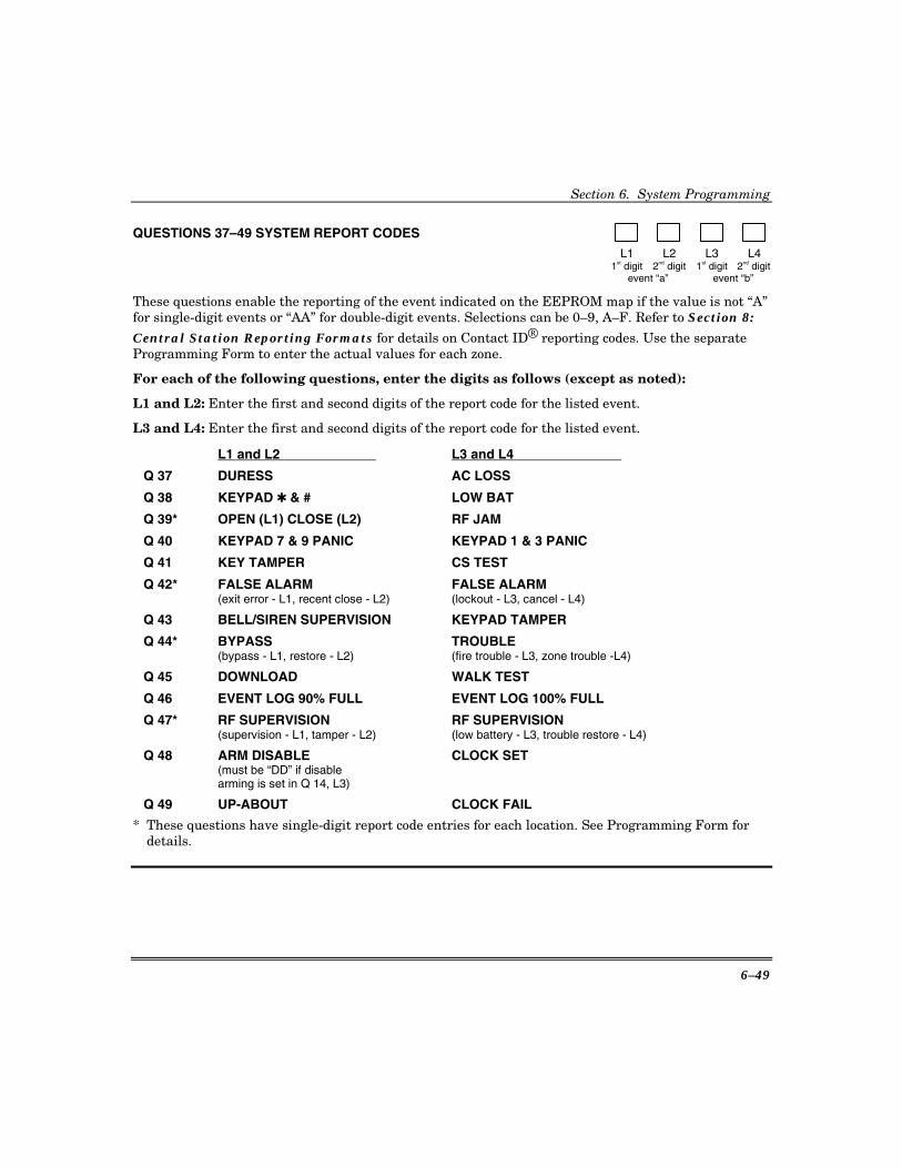
Section 6. System Programming
6–49
QUESTIONS 37–49 SYSTEM REPORT CODES
L1 L2 L3 L4 1st digit 2nd digit 1st digit 2nd digit event “a” event “b”
These questions enable the reporting of the event indicated on the EEPROM map if the value is not “A” for single-digit events or “AA” for double-digit events. Selections can be 0–9, A–F. Refer to Section 8: Central Station Reporting Formats for details on Contact ID® reporting codes. Use the separate Programming Form to enter the actual values for each zone.
For each of the following questions, enter the digits as follows (except as noted):
L1 and L2: Enter the first and second digits of the report code for the listed event.
L3 and L4: Enter the first and second digits of the report code for the listed event.
L1 and L2 L3 and L4
Q 37 DURESS AC LOSS
Q 38 KEYPAD ✱ & # LOW BAT
Q 39* OPEN (L1) CLOSE (L2) RF JAM
Q 40 KEYPAD 7 & 9 PANIC KEYPAD 1 & 3 PANIC
Q 41 KEY TAMPER CS TEST
Q 42* FALSE ALARM (exit error - L1, recent close - L2)
FALSE ALARM (lockout - L3, cancel - L4)
Q 43 BELL/SIREN SUPERVISION KEYPAD TAMPER
Q 44* BYPASS (bypass - L1, restore - L2)
TROUBLE (fire trouble - L3, zone trouble -L4)
Q 45 DOWNLOAD WALK TEST
Q 46 EVENT LOG 90% FULL EVENT LOG 100% FULL
Q 47* RF SUPERVISION (supervision - L1, tamper - L2)
RF SUPERVISION (low battery - L3, trouble restore - L4)
Q 48 ARM DISABLE (must be “DD” if disable arming is set in Q 14, L3)
CLOCK SET
Q 49 UP-ABOUT CLOCK FAIL
* These questions have single-digit report code entries for each location. See Programming Form for details.
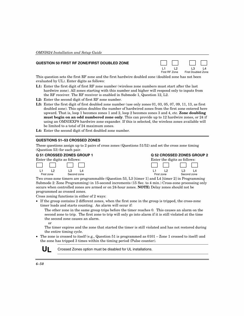
OMNI624 Installation and Setup Guide
6–50
QUESTION 50 FIRST RF ZONE/FIRST DOUBLED ZONE
L1 L2 L3 L4 First RF Zone First Doubled Zone
This question sets the first RF zone and the first hardwire doubled zone (doubled zone has not been evaluated by UL). Enter digits as follows: L1: Enter the first digit of first RF zone number (wireless zone numbers must start after the last
hardwire zone). All zones starting with this number and higher will respond only to inputs from the RF receiver. The RF receiver is enabled in Submode 1, Question 12, L2.
L2: Enter the second digit of first RF zone number. L3: Enter the first digit of first doubled zone number (use only zones 01, 03, 05, 07, 09, 11, 13, as first
doubled zone). This option doubles the number of hardwired zones from the first zone entered here upward. That is, loop 1 becomes zones 1 and 2, loop 2 becomes zones 3 and 4, etc. Zone doubling must begin on an odd numbered zone only. This can provide up to 12 hardwire zones, or 24 if using an OMNIEXP8 hardwire zone expander. If this is selected, the wireless zones available will be limited to a total of 24 maximum zones.
L4: Enter the second digit of first doubled zone number.
QUESTIONS 51–53 CROSSED ZONES These questions assign up to 2 pairs of cross zones (Questions 51/52) and set the cross zone timing (Question 53) for each pair. Q 51 CROSSED ZONES GROUP 1 Q 52 CROSSED ZONES GROUP 2 Enter the digits as follows: Enter the digits as follows:
L1 L2 L3 L4 L1 L2 L3 L4 First zone Second zone First zone Second zone
Two cross-zone timers are programmable (Question 53, L3 [timer 1] and L4 [timer 2] in Programming Submode 2: Zone Programming) in 15-second increments (15 Sec. to 4 min.) Cross-zone processing only occurs when controlled zones are armed or on 24-hour zones. NOTE: Delay zones should not be programmed as crossed zones. Cross zoning functions in either of 2 ways: • If the group contains 2 different zones, when the first zone in the group is tripped, the cross-zone
timer loads and starts counting. An alarm will occur if: The other zone in the same group trips before the timer reaches 0. This causes an alarm on the
second zone to trip. The first zone to trip will only go into alarm if it is still violated at the time the second zone causes an alarm.
or The timer expires and the zone that started the timer is still violated and has not restored during
the entire timing cycle. • The zone is crossed to itself (e.g., Question 51 is programmed as 0101 – Zone 1 crossed to itself) and
the zone has tripped 3 times within the timing period (Pulse counter).
UL Crossed Zones option must be disabled for UL installations.
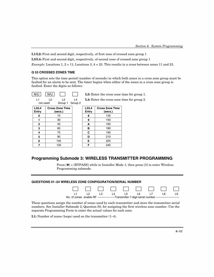
Section 6. System Programming
6–51
L1/L2: First and second digit, respectively, of first zone of crossed zone group 1
L3/L4: First and second digit, respectively, of second zone of crossed zone group 1
Example: Locations 1, 2 = 11; Locations 3, 4 = 23. This results in a cross between zones 11 and 23.
Q 53 CROSSED ZONES TIME
This option sets the time period (number of seconds) in which both zones in a cross zone group must be faulted for an alarm to be sent. The timer begins when either of the zones in a cross zone group is faulted. Enter the digits as follows:
N/U N/U L3: Enter the cross zone time for group 1.
L1 L2 L3 L4 L4: Enter the cross zone time for group 2. not used Group 1 Group 2
L3/L4 Entry
Cross Zone Time (secs.)
L3/L4Entry
Cross Zone Time (secs.)
0 15 8 135
1 30 9 150
2 45 A 165
3 60 B 180
4 75 C 195
5 90 D 210
6 105 E 225
7 120 F 240
Programming Submode 3: WIRELESS TRANSMITTER PROGRAMMING Press [✱] + [BYPASS] while in Installer Mode 1, then press [3] to enter Wireless Programming submode.
QUESTIONS 01–24 WIRELESS ZONE CONFIGURATION/SERIAL NUMBER
L1 L2 L3 L4 L5 L6 L7 L8 L9 No. of zones enable RF –––––––––––Transmitter 7-digit serial number –––––––––––––––
These questions assign the number of zones used by each transmitter and store the transmitter serial numbers. See Installer Submode 2, Question 50, for assigning the first wireless zone number. Use the separate Programming Form to enter the actual values for each zone.
L1: Number of zones (loops) used on the transmitter (1–4).

OMNI624 Installation and Setup Guide
6–52
NOTE: When using multiple zones (loops) on a transmitter, the first zone number will contain the transmitter information and the following zones are automatically assigned and will contain zeros. For example, if you enter 2 in L1 and the first zone is number 15, zone 16 will automatically be assigned and will contain zeros.
L2: Should always be “1,” unless you want to swap the order of zone numbering for the transmitter’s loops 1 and 2 and not use loop 1, in which case enter “9.” For example, if you are using a 2-loop transmitter such as the ZR510 or 5816 and only want to use the magnetic reed switch (loop 2) you would enter 9 so that loop 2 would be treated as loop 1. NOTE: When you swap the order of the loops in the transmitter by entering a 9, enter a 1 as the L1 entry to use one loop.
L3–L9: Enter the transmitter’s 7-digit serial number.
NOTES: • The [#] key must be pressed after the last digit of a serial number entry so that the serial number is
correctly stored into memory. • The zones corresponding to a transmitter’s loops must all be in the same partition when using
transmitters with multiple loops. Q 01 WIRELESS ZONE 1 Q 09 WIRELESS ZONE 9 Q 17 WIRELESS ZONE 17 Q 02 WIRELESS ZONE 2 Q 10 WIRELESS ZONE 10 Q 18 WIRELESS ZONE 18 Q 03 WIRELESS ZONE 3 Q 11 WIRELESS ZONE 11 Q 19 WIRELESS ZONE 19 Q 04 WIRELESS ZONE 4 Q 12 WIRELESS ZONE 12 Q 20 WIRELESS ZONE 20 Q 05 WIRELESS ZONE 5 Q 13 WIRELESS ZONE 13 Q 21 WIRELESS ZONE 21 Q 06 WIRELESS ZONE 6 Q 14 WIRELESS ZONE 14 Q 22 WIRELESS ZONE 22 Q 07 WIRELESS ZONE 7 Q 15 WIRELESS ZONE 15 Q 23 WIRELESS ZONE 23 Q 08 WIRELESS ZONE 8 Q 16 WIRELESS ZONE 16 Q 24 WIRELESS ZONE 24
QUESTION 25–32 KEYFOB CONFIGURATION/SERIAL NUMBER
L1 L2 L3 L4 L5 L6 L7 L8 L9 No. of buttons enable RF –––––––––––––Keyfob 7-digit serial number –––––––––––––––––
These questions assign the number of buttons used by each keyfob and store the keyfob’s serial numbers. See Installer Submode 1, Questions 49–64 to assign the keyfob button functions. Use the separate Programming Form to enter the actual values for each keyfob. L1: Number of buttons used on the transmitter (1–4). L2: Should always be “1.” L3–L9: Enter the keyfob’s 7-digit serial number. NOTES: • The [#] key must be pressed after the last digit of a serial number entry so that the serial number is
correctly stored into memory. • The zones corresponding to a keyfob’s loops must all be in the same partition when using keyfobs
with multiple loops.

Section 6. System Programming
6–53
Q 25 KEYFOB 1 CONFIGURATION/SERIAL NUMBER Q 26 KEYFOB 2 CONFIGURATION/SERIAL NUMBER Q 27 KEYFOB 3 CONFIGURATION/SERIAL NUMBER Q 28 KEYFOB 4 CONFIGURATION/SERIAL NUMBER Q 29 KEYFOB 5 CONFIGURATION/SERIAL NUMBER Q 30 KEYFOB 6 CONFIGURATION/SERIAL NUMBER Q 31 KEYFOB 7 CONFIGURATION/SERIAL NUMBER Q 32 KEYFOB 8 CONFIGURATION/SERIAL NUMBER
Programming Submode 4: DESCRIPTOR PROGRAMMING Press [✱] [BYPASS] while in Installer Mode 1, then press [4] to enter Descriptor Programming submode.
To create a descriptor: 1. Press [✱] then the Question number representing the zone number desired.
2. Press the INSTANT key to move the cursor to the desired location within that Question. 3. Press one of the character display keys (see table below) to display the character set. 4. When the desired character appears, press INSTANT. The character is accepted and the cursor
moves to the next location. To move to a previous location to change a character, if needed, press CODE.
5. When the descriptor is complete, accept the entry by pressing [✱] then the next Question number.
Refer to the following chart when entering descriptors:
Key Function
INSTANT Accepts displayed character and moves cursor forward one position.
CODE Moves cursor backward one position.
[7] Displays next character in character set.
[9] Displays previous character in character set.
[#] [7] Automatically scrolls character set display forward.
[#] [9] Automatically scrolls character set display backward.
[8] Stops auto scrolling.
[0] Inserts a blank character.
QUESTIONS 01–24 ZONE DESCRIPTORS FOR ZONES 01–24
L1 L2 L3 L4 L5 L6 L7 L8 L9 L10 L11 L12 L13 L14 L15 L16

OMNI624 Installation and Setup Guide
6–54
These questions allow you to enter up to 16-digit descriptors for each zone. Each digit corresponds to a single descriptor character. Use the separate Programming Form to enter the actual descriptors for each zone.
Descriptor For: Descriptor For: Descriptor For: Descriptor For: Q 01 ZONE 1 Q 07 ZONE 7 Q 13 ZONE 13 Q 19 ZONE 19 Q 02 ZONE 2 Q 08 ZONE 8 Q 14 ZONE 14 Q 20 ZONE 20 Q 03 ZONE 3 Q 09 ZONE 9 Q 15 ZONE 15 Q 21 ZONE 21 Q 04 ZONE 4 Q 10 ZONE 10 Q 16 ZONE 16 Q 22 ZONE 22 Q 05 ZONE 5 Q 11 ZONE 11 Q 17 ZONE 17 Q 23 ZONE 23 Q 06 ZONE 6 Q 12 ZONE 12 Q 18 ZONE 18 Q 24 ZONE 24
QUESTIONS 25–26 PARTITION DESCRIPTORS
L1 L2 L3 L4 L5 L6 L7 L8 L9 L10 L11 L12 L13 L14 L15 L16
This question allows you to enter up to 16 digits for partitions 1 and 2. Each digit corresponds to a single character in the descriptor.
Q 25 DESCRIPTOR FOR PARTITION 1 Q 26 DESCRIPTOR FOR PARTITION 2
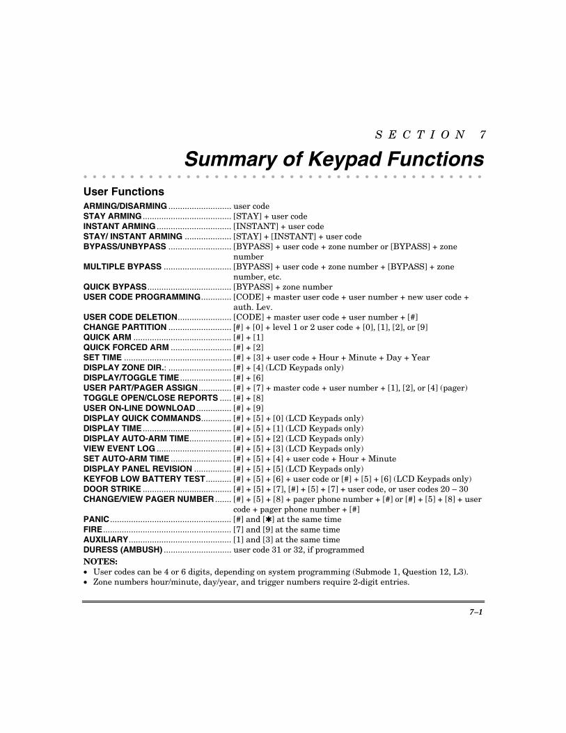
7–1
S E C T I O N 7
Summary of Keypad Functions • • • • • • • • • • • • • • • • • • • • • • • • • • • • • • • • • • • • • • • • • • •
User Functions ARMING/DISARMING ........................... user code STAY ARMING ...................................... [STAY] + user code INSTANT ARMING ................................ [INSTANT] + user code STAY/ INSTANT ARMING .................... [STAY] + [INSTANT] + user code BYPASS/UNBYPASS ........................... [BYPASS] + user code + zone number or [BYPASS] + zone
number MULTIPLE BYPASS ............................. [BYPASS] + user code + zone number + [BYPASS] + zone
number, etc. QUICK BYPASS.................................... [BYPASS] + zone number USER CODE PROGRAMMING............. [CODE] + master user code + user number + new user code +
auth. Lev. USER CODE DELETION....................... [CODE] + master user code + user number + [#] CHANGE PARTITION ........................... [#] + [0] + level 1 or 2 user code + [0], [1], [2], or [9] QUICK ARM .......................................... [#] + [1] QUICK FORCED ARM .......................... [#] + [2] SET TIME .............................................. [#] + [3] + user code + Hour + Minute + Day + Year DISPLAY ZONE DIR.: ........................... [#] + [4] (LCD Keypads only) DISPLAY/TOGGLE TIME ...................... [#] + [6] USER PART/PAGER ASSIGN .............. [#] + [7] + master code + user number + [1], [2], or [4] (pager) TOGGLE OPEN/CLOSE REPORTS ..... [#] + [8] USER ON-LINE DOWNLOAD ............... [#] + [9] DISPLAY QUICK COMMANDS............. [#] + [5] + [0] (LCD Keypads only) DISPLAY TIME ...................................... [#] + [5] + [1] (LCD Keypads only) DISPLAY AUTO-ARM TIME.................. [#] + [5] + [2] (LCD Keypads only) VIEW EVENT LOG ................................ [#] + [5] + [3] (LCD Keypads only) SET AUTO-ARM TIME .......................... [#] + [5] + [4] + user code + Hour + Minute DISPLAY PANEL REVISION ................ [#] + [5] + [5] (LCD Keypads only) KEYFOB LOW BATTERY TEST........... [#] + [5] + [6] + user code or [#] + [5] + [6] (LCD Keypads only) DOOR STRIKE ...................................... [#] + [5] + [7], [#] + [5] + [7] + user code, or user codes 20 – 30 CHANGE/VIEW PAGER NUMBER ....... [#] + [5] + [8] + pager phone number + [#] or [#] + [5] + [8] + user
code + pager phone number + [#] PANIC .................................................... [#] and [✱] at the same time FIRE....................................................... [7] and [9] at the same time AUXILIARY............................................ [1] and [3] at the same time DURESS (AMBUSH) ............................. user code 31 or 32, if programmed NOTES: • User codes can be 4 or 6 digits, depending on system programming (Submode 1, Question 12, L3). • Zone numbers hour/minute, day/year, and trigger numbers require 2-digit entries.

OMNI624 Installation and Setup Guide
7–2
Installer Modes KEYPAD PROGRAMMING ................... [CODE] + [✱] + installer code + [1] + 1–4 submode
DEFAULT USER CODES...................... [CODE] + [✱] + installer code + [1] + 1–4 submode; then press [7] and [9] at the same time
PROGRAM REVIEW MODE.................. [CODE] + [✱] + installer code + [2]
WALK TEST .......................................... [CODE] + [✱] + installer code + [3]
SYSTEM LOG VIEW ............................. [CODE] + [✱] + installer code + [4]
CLEAR SYSTEM LOG .......................... [CODE] + [✱] + installer code + [4] + [BYPASS]
SYSTEM DEFAULT............................... [CODE] + [✱] + installer code + [5] + [5] or [CODE] + [✱] + installer code + [1] + 1–4 submode; then press [1] and [3] at the same time
CLEAR TAMPERS ................................ [CODE] + [✱] + installer code + [6]
UNATTENDED DOWNLOAD ................ [CODE] + [✱] + installer code + [8]
ON-LINE DOWNLOAD .......................... [CODE] + [✱] + installer code + [9]
NOTES: • Installer code can be 4 or 6 digits, depending on system programming (Installer Mode 1, Submode 1,
Question 12, L3).
• Pressing [STAY] exits installer mode. Installer mode will also automatically exit if no keys are pressed for a period of time.

8–1
S E C T I O N 8
Central Station Reporting Formats • • • • • • • • • • • • • • • • • • • • • • • • • • • • • • • • • • • • • • • • • • •
General Information This security system is designed to transmit data to a central station receiver when an alarm, system trouble, or an opening/closing occurs. Due to the many different types of CS receivers in the market, this system can transmit data in various formats. Each installing company determines which format best suits its needs based on many factors. Of these, the CS receiver type is a major factor.
In transmitting data to the CS receiver, first the system's digital communicator seizes the home phone lines. Then it dials the CS#1 telephone number. When the CS receiver picks up the ringing phone line, it transmits a “Handshake” frequency (1400Hz, 2300Hz or HiLo) back to the digital communicator. After receiving the “Handshake” frequency, the digital communicator transmits the data in the format programmed in Submode 1, Question 10, L1–L4. Assuming the CS receiver verifies the data transmission as valid (after 2 successful rounds of data or 1 valid parity round), it transmits a “Kissoff” frequency back to the digital communicator. This causes the communicator to stop transmitting, unless more data is available, in which case additional data transmissions and “Kissoffs” occur. After the final “Kissoff,” the CS receiver releases the phone line and processes the data to its display and associated peripherals (computer and printer). If for any reason the digital communicator does not receive the “Kissoff,” it proceeds to dial the CS#2 telephone number or re-dials the CS#1 telephone number (if CS#2 is not used). It will continue to dial for a programmed number of times until a “Kissoff” is received. If after all programmed dialing attempts to each CS Telephone number, a “Kissoff” is not received, the system will display “Communication Failure” at the keypad. This message is cleared after it is acknowledged by the user at the keypad.
The following is a general description of the various formats transmitted by this system.
Standard (3x1 or 4x1) The Standard Reporting Format: AAA E or AAAA E where:
AAAA = Three- or four-digit account number E = Single-digit event code; it is the first of the 2 programmable reporting code digits
Standard format is transmitted in Pulse, and involves a 3- or 4-digit account number followed by a single-digit event code. It can be transmitted with parity (1 round of data) or without parity (2 rounds of data). A disadvantage of this format is that it can transmit a total of only 15 event codes (0–9, B–F) without identifying zones or users. Examples:
3x1 w/o PARITY 3x1 w/PARITY 123 3 (1st round) 123 3 6 (single round) 123 3 (2nd round) 123 3 (resulting data) 123 3 (resulting data)
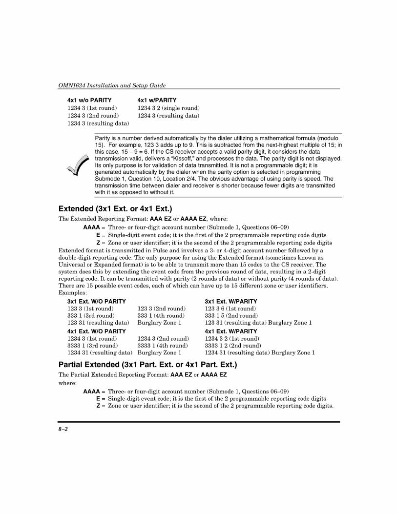
OMNI624 Installation and Setup Guide
8–2
4x1 w/o PARITY 4x1 w/PARITY 1234 3 (1st round) 1234 3 2 (single round) 1234 3 (2nd round) 1234 3 (resulting data) 1234 3 (resulting data)
Parity is a number derived automatically by the dialer utilizing a mathematical formula (modulo 15). For example, 123 3 adds up to 9. This is subtracted from the next-highest multiple of 15; in this case, 15 – 9 = 6. If the CS receiver accepts a valid parity digit, it considers the data transmission valid, delivers a “Kissoff,” and processes the data. The parity digit is not displayed. Its only purpose is for validation of data transmitted. It is not a programmable digit; it is generated automatically by the dialer when the parity option is selected in programming Submode 1, Question 10, Location 2/4. The obvious advantage of using parity is speed. The transmission time between dialer and receiver is shorter because fewer digits are transmitted with it as opposed to without it.
Extended (3x1 Ext. or 4x1 Ext.) The Extended Reporting Format: AAA EZ or AAAA EZ, where: AAAA = Three- or four-digit account number (Submode 1, Questions 06–09) E = Single-digit event code; it is the first of the 2 programmable reporting code digits Z = Zone or user identifier; it is the second of the 2 programmable reporting code digits Extended format is transmitted in Pulse and involves a 3- or 4-digit account number followed by a double-digit reporting code. The only purpose for using the Extended format (sometimes known as Universal or Expanded format) is to be able to transmit more than 15 codes to the CS receiver. The system does this by extending the event code from the previous round of data, resulting in a 2-digit reporting code. It can be transmitted with parity (2 rounds of data) or without parity (4 rounds of data). There are 15 possible event codes, each of which can have up to 15 different zone or user identifiers. Examples:
3x1 Ext. W/O PARITY 3x1 Ext. W/PARITY 123 3 (1st round) 123 3 (2nd round) 123 3 6 (1st round) 333 1 (3rd round) 333 1 (4th round) 333 1 5 (2nd round) 123 31 (resulting data) Burglary Zone 1 123 31 (resulting data) Burglary Zone 1 4x1 Ext. W/O PARITY 4x1 Ext. W/PARITY 1234 3 (1st round) 1234 3 (2nd round) 1234 3 2 (1st round) 3333 1 (3rd round) 3333 1 (4th round) 3333 1 2 (2nd round) 1234 31 (resulting data) Burglary Zone 1 1234 31 (resulting data) Burglary Zone 1
Partial Extended (3x1 Part. Ext. or 4x1 Part. Ext.) The Partial Extended Reporting Format: AAA EZ or AAAA EZ where: AAAA = Three- or four-digit account number (Submode 1, Questions 06–09) E = Single-digit event code; it is the first of the 2 programmable reporting code digits Z = Zone or user identifier; it is the second of the 2 programmable reporting code digits.
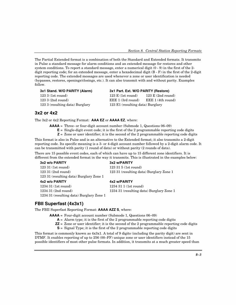
Section 8. Central Station Reporting Formats
8–3
The Partial Extended format is a combination of both the Standard and Extended formats. It transmits in Pulse a standard message for alarm conditions and an extended message for restores and other system conditions. To report a standard message, enter a numerical digit (0 - 9) in the first of the 2-digit reporting code; for an extended message, enter a hexadecimal digit (B - F) in the first of the 2-digit reporting code. The extended messages are used whenever a zone or user identification is needed (bypasses, restores, openings/closings, etc.). It can also transmit with and without parity. Examples follow.
3x1 Stand. W/O PARITY (Alarm) 3x1 Part. Ext. W/O PARITY (Restore) 123 3 (1st round) 123 E (1st round) 123 E (2nd round) 123 3 (2nd round) EEE 1 (3rd round) EEE 1 (4th round) 123 3 (resulting data) Burglary 123 E1 (resulting data) Burglary
3x2 or 4x2 The 3x2 or 4x2 Reporting Format: AAA EZ or AAAA EZ, where:
AAAA = Three- or four-digit account number (Submode 1, Questions 06–09) E = Single-digit event code; it is the first of the 2 programmable reporting code digits Z = Zone or user identifier; it is the second of the 2 programmable reporting code digits
This format is also in Pulse and is an alternative to the Extended format; it also transmits a 2-digit reporting code. Its specific meaning is a 3- or 4-digit account number followed by a 2-digit alarm code. It can be transmitted with parity (1 round of data) or without parity (2 rounds of data).
There are 15 possible event codes, each of which can have up to 15 different zone identifiers. It is different from the extended format in the way it transmits. This is illustrated in the examples below:
3x2 w/o PARITY 3x2 w/PARITY 123 31 (1st round) 123 31 5 (1st round) 123 31 (2nd round) 123 31 (resulting data) Burglary Zone 1 123 31 (resulting data) Burglary Zone 1 4x2 w/o PARITY 4x2 w/PARITY 1234 31 (1st round) 1234 31 1 (1st round) 1234 31 (2nd round) 1234 31 (resulting data) Burglary Zone 1 1234 31 (resulting data) Burglary Zone 1
FBII Superfast (4x3x1) The FBII Superfast Reporting Format: AAAA AZZ S, where:
AAAA = Four-digit account number (Submode 1, Questions 06–09) A = Alarm type; it is the first of the 2 programmable reporting code digits ZZ = Zone or user identifier; it is the second of the 2 programmable reporting code digits S = Signal Type; it is the first of the 2 programmable reporting code digits
This format is commonly known as 4x3x1. A total of 9 digits (including the parity digit) are sent in DTMF. It enables reporting of up to 256 (00–FF) unique zone or user identifiers instead of the 15 possible identifiers of most other pulse formats. In addition, it transmits at a much greater speed than

OMNI624 Installation and Setup Guide
8–4
the conventional pulse formats, since it uses DTMF (touch-tones) instead of pulses to transmit the data and it always sends a parity digit.
For alarms, openings and closings, the Alarm Type digit will be the same as the Signal Type. This indicates the type of activity or condition that has occurred. However, on bypasses, restores and troubles, the Alarm Type will not be the same as the Signal Type. Instead, the Signal Type will change, indicating the current condition of the zone.
NOTE: This is a unique feature of this format that allows more intelligent reporting of the activity occurring in the system. For instance, the following unique messages can be transmitted:
1234 1 01 1 Fire Zone 001
1234 1 01 E Restore Fire Zone 001
1234 1 01 F Trouble Fire Zone 001
ADEMCO 4x1 Express The 4x1 Express Reporting Format: AAAA 17 E, where: AAAA = Three- or four-digit account number (Submode 1, Questions 06–09) 17 = Uniquely identifies this format to the receiver and to an automation system, but is
not displayed or printed. E = Single-digit event code; it is the first of the 2 programmable reporting code digits
This format transmits in DTMF a total of 6 digits (including the parity digit). It is similar to the Standard format in that it can transmit a total of only 15 reporting codes. However, its advantage is speed because it transmits touch-tones instead of pulses and it always sends a parity digit. Examples:
123 3 6 (1st round) 123 3 (resulting data) Burglary
ADEMCO 4x2 Express The 4x2 Express Reporting Format: AAAA 27 EZ, where: AAAA = Three- or four-digit account number (Submode 1, Questions 06–09) 27 = Uniquely identifies this format to the receiver and to an automation system but is
not displayed or printed E = Single-digit event code; it is the first of the 2 programmable reporting code digits Z = Zone or user identifier; it is the second of the 2 programmable reporting code digits
This format transmits in DTMF a total of 7 digits (including the parity digit). This format is similar to the 4x1 Extended and 4x2 formats in that the output sends a 4-digit account and 2-digit event code. However, its advantage is speed because it transmits touch-tones instead of pulses and it always sends a parity digit. Examples:
1234 31 1 (1st round) 1234 31 (resulting data) Burglary Zone 1
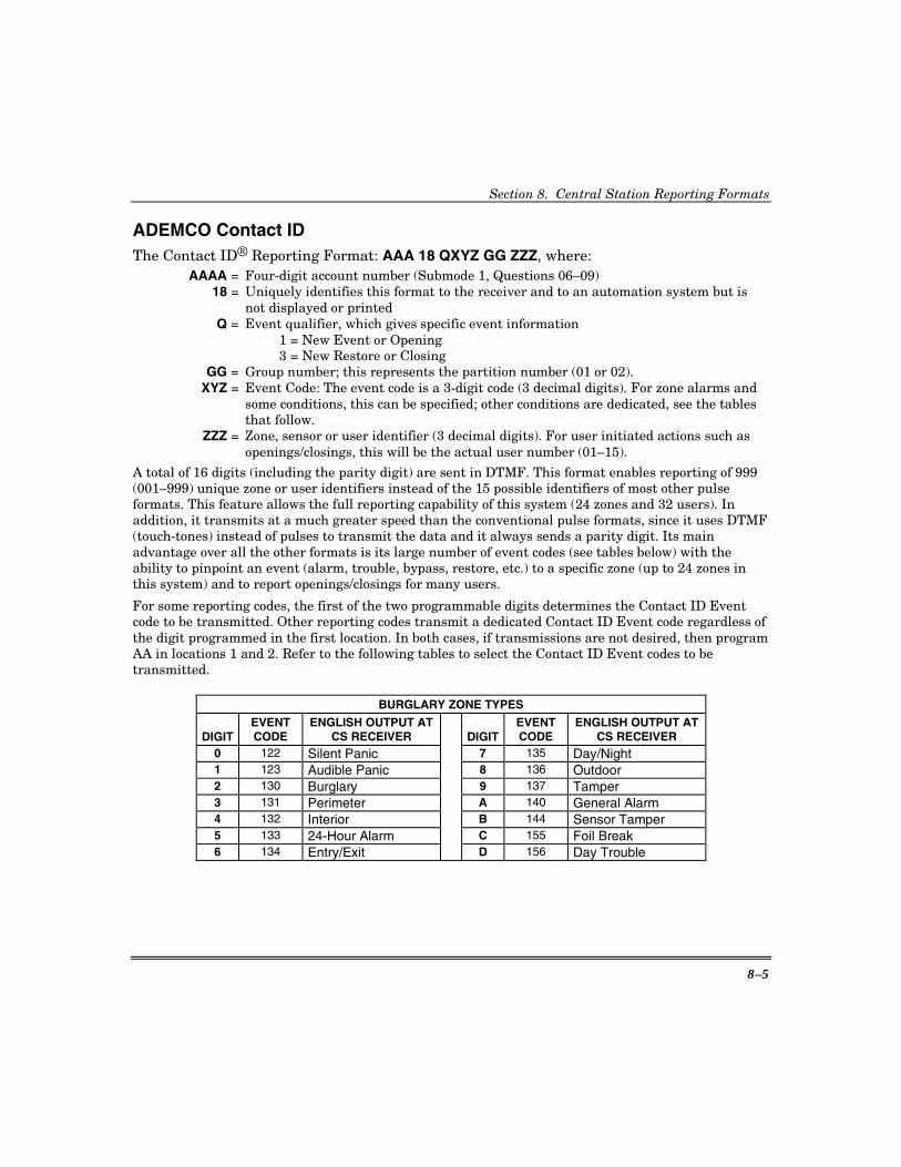
Section 8. Central Station Reporting Formats
8–5
ADEMCO Contact ID The Contact ID® Reporting Format: AAA 18 QXYZ GG ZZZ, where: AAAA = Four-digit account number (Submode 1, Questions 06–09) 18 = Uniquely identifies this format to the receiver and to an automation system but is
not displayed or printed Q = Event qualifier, which gives specific event information
1 = New Event or Opening 3 = New Restore or Closing
GG = Group number; this represents the partition number (01 or 02). XYZ = Event Code: The event code is a 3-digit code (3 decimal digits). For zone alarms and
some conditions, this can be specified; other conditions are dedicated, see the tables that follow.
ZZZ = Zone, sensor or user identifier (3 decimal digits). For user initiated actions such as openings/closings, this will be the actual user number (01–15).
A total of 16 digits (including the parity digit) are sent in DTMF. This format enables reporting of 999 (001–999) unique zone or user identifiers instead of the 15 possible identifiers of most other pulse formats. This feature allows the full reporting capability of this system (24 zones and 32 users). In addition, it transmits at a much greater speed than the conventional pulse formats, since it uses DTMF (touch-tones) instead of pulses to transmit the data and it always sends a parity digit. Its main advantage over all the other formats is its large number of event codes (see tables below) with the ability to pinpoint an event (alarm, trouble, bypass, restore, etc.) to a specific zone (up to 24 zones in this system) and to report openings/closings for many users.
For some reporting codes, the first of the two programmable digits determines the Contact ID Event code to be transmitted. Other reporting codes transmit a dedicated Contact ID Event code regardless of the digit programmed in the first location. In both cases, if transmissions are not desired, then program AA in locations 1 and 2. Refer to the following tables to select the Contact ID Event codes to be transmitted.
BURGLARY ZONE TYPES
DIGIT EVENT CODE
ENGLISH OUTPUT AT CS RECEIVER DIGIT
EVENT CODE
ENGLISH OUTPUT AT CS RECEIVER
0 122 Silent Panic 7 135 Day/Night 1 123 Audible Panic 8 136 Outdoor 2 130 Burglary 9 137 Tamper 3 131 Perimeter A 140 General Alarm 4 132 Interior B 144 Sensor Tamper 5 133 24-Hour Alarm C 155 Foil Break 6 134 Entry/Exit D 156 Day Trouble

OMNI624 Installation and Setup Guide
8–6
FIRE ZONE TYPES
DIGIT EVENT CODE
ENGLISH OUTPUT AT CS RECEIVER DIGIT
EVENT CODE
ENGLISH OUTPUT AT CS RECEIVER
0 110 Fire Alarm 8 140 General Alarm 1 111 Smoke 9 150 24-Hour Non-Burg 2 112 Combustion A 158 High Temperature 3 113 Water Flow B 159 Low Temperature 4 114 Heat C 200 Fire Supervisory 5 115 Pull Station D 201 Low H2O Pressure 6 116 Duct E 202 Low CO2 7 117 Flame F 203 Gate Valve Sensor
24-HOUR ALARM TYPES
DIGIT EVENT CODE
ENGLISH OUTPUT AT CS RECEIVER DIGIT
EVENT CODE
ENGLISH OUTPUT AT CS RECEIVER
0 100 Medical 8 137 Tamper
1 101 Pendant Transmitter 9 140 General Alarm
2 120 Panic Alarm A 150 24-Hour Non-Burg
3 122 Silent Panic B 151 Gas Detected
4 123 Audible Panic C 152 Refrigeration
5 130 Burglary D 153 Loss of Heat
6 133 24-Hour Alarm E 154 Water Leakage
7 135 Day/Night F 155 Foil Break
24-HOUR TROUBLE TYPES
DIGIT EVENT CODE
ENGLISH OUTPUT AT CS RECEIVER DIGIT
EVENT CODE
ENGLISH OUTPUT AT CS RECEIVER
0 100 Medical 8 158 High Temperature
1 122 Silent Panic 9 159 Low Temperature
2 123 Audible Panic A 300 System Trouble
3 137 Tamper B 301 AC Loss
4 150 24-Hour Non-Burg C 302 Low System Battery
5 153 Loss of Heat D 310 Ground Fault
6 155 Foil Break E 373 Fire Trouble
7 156 Day Trouble F 380 Sensor Trouble
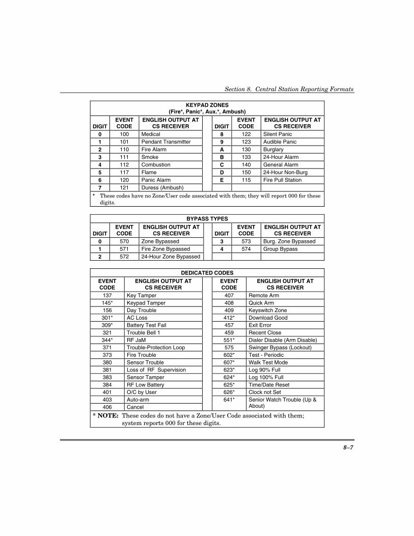
Section 8. Central Station Reporting Formats
8–7
KEYPAD ZONES (Fire*, Panic*, Aux.*, Ambush)
DIGIT EVENT CODE
ENGLISH OUTPUT AT CS RECEIVER DIGIT
EVENT CODE
ENGLISH OUTPUT AT CS RECEIVER
0 100 Medical 8 122 Silent Panic 1 101 Pendant Transmitter 9 123 Audible Panic 2 110 Fire Alarm A 130 Burglary 3 111 Smoke B 133 24-Hour Alarm 4 112 Combustion C 140 General Alarm 5 117 Flame D 150 24-Hour Non-Burg 6 120 Panic Alarm E 115 Fire Pull Station 7 121 Duress (Ambush)
* These codes have no Zone/User code associated with them; they will report 000 for these digits.
BYPASS TYPES
DIGIT EVENT CODE
ENGLISH OUTPUT AT CS RECEIVER DIGIT
EVENT CODE
ENGLISH OUTPUT AT CS RECEIVER
0 570 Zone Bypassed 3 573 Burg. Zone Bypassed 1 571 Fire Zone Bypassed 4 574 Group Bypass 2 572 24-Hour Zone Bypassed
DEDICATED CODES
EVENT CODE
ENGLISH OUTPUT AT CS RECEIVER
EVENT CODE
ENGLISH OUTPUT AT CS RECEIVER
137 Key Tamper 407 Remote Arm 145* Keypad Tamper 408 Quick Arm 156 Day Trouble 409 Keyswitch Zone 301* AC Loss 412* Download Good 309* Battery Test Fail 457 Exit Error 321 Trouble Bell 1 459 Recent Close 344* RF JaM 551* Dialer Disable (Arm Disable) 371 Trouble-Protection Loop 575 Swinger Bypass (Lockout) 373 Fire Trouble 602* Test - Periodic 380 Sensor Trouble 607* Walk Test Mode 381 Loss of RF Supervision 623* Log 90% Full 383 Sensor Tamper 624* Log 100% Full 384 RF Low Battery 625* Time/Date Reset 401 O/C by User 626* Clock not Set 403 Auto-arm 406 Cancel
641* Senior Watch Trouble (Up & About)
* NOTE: These codes do not have a Zone/User Code associated with them; system reports 000 for these digits.

OMNI624 Installation and Setup Guide
8–8
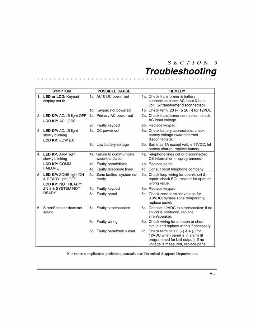
9–1
S E C T I O N 9
Troubleshooting • • • • • • • • • • • • • • • • • • • • • • • • • • • • • • • • • • • • • • • • • • •
SYMPTOM POSSIBLE CAUSE REMEDY
1a. AC & DC power out 1a. Check transformer & battery connection; check AC input & batt. volt. (w/transformer disconnected).
1. LED or LCD: Keypad display not lit.
1b. Keypad not powered 1b. Check term. 23 (+) & 20 (-) for 12VDC.2a. Primary AC power out 2a. Check transformer connection; check
AC input voltage. 2. LED KP: AC/LB light OFF LCD KP: AC LOSS
2b. Faulty keypad 2b. Replace keypad 3a. DC power out 3a. Check battery connections; check
battery voltage (w/transformer disconnected).
3. LED KP: AC/LB light slowly blinking
LCD KP: LOW BAT 3b. Low battery voltage 3b. Same as 3A except volt. < 11VDC; let
battery charge; replace battery. 4a. Failure to communicate
w/central station 4a. Telephone lines cut or disconnected;
CS information misprogrammed. 4b. Faulty panel/dialer 4b. Replace panel.
4. LED KP: ARM light slowly blinking
LCD KP: COMM FAILURE 4c. Faulty telephone lines 4c. Consult local telephone company.
5a. Zone faulted; system not ready
5a. Check loop wiring for open/short & repair: check EOL resistor for open or wrong value.
5b. Faulty keypad 5b. Replace keypad.
5. LED KP: ZONE light ON & READY light OFF
LCD KP: NOT READY: ZN # & SYSTEM NOT READY 5c. Faulty panel 5c. Check zone terminal voltage for
3.3VDC; bypass zone temporarily; replace panel.
6a. Faulty siren/speaker 6a. Connect 12VDC to siren/speaker; if no sound is produced, replace siren/speaker.
6b. Faulty wiring 6b. Check wiring for an open or short circuit and replace wiring if necessary.
6. Siren/Speaker does not sound
6c. Faulty panel/bell output 6c. Check terminals 3 (+) & 4 (-) for 12VDC when panel is in alarm (if programmed for bell output). If no voltage is measured, replace panel.
For more complicated problems, consult our Technical Support Department.

OMNI624 Installation and Setup Guide
9–2

10–1
S E C T I O N 1 0
Regulatory/Limitations Statements • • • • • • • • • • • • • • • • • • • • • • • • • • • • • • • • • • • • • • • • • • •
RADIO FREQUENCY EMISSIONS STATEMENTS
FEDERAL COMMUNICATIONS COMMISSION (FCC) Part 15 This device complies with part 15 of the FCC rules. Operation is subject to the following two conditions: (1) This device may not cause harmful interference, and (2) this device must accept any interference received, including interference that may cause undesired operation.
INDUSTRY CANADA This Class B digital apparatus complies with Canadian ICES-003.
Cet Appareil numérique de la classe B est conforme à la norme NMB-003 du Canada.
TELEPHONE/MODEM INTERFACE STATEMENTS
FEDERAL COMMUNICATIONS COMMISSION (FCC) Part 68 This equipment complies with Part 68 of the FCC rules. On the front cover of this equipment is a label that contains the FCC registration number and Ringer Equivalence Number (REN). You must provide this information to the telephone company when requested.
This equipment uses the following USOC jack: RJ31X
This equipment may not be used on telephone-company-provided coin service. Connection to party lines is subject to state tariffs. This equipment is hearing-aid compatible.
INDUSTRY CANADA NOTICE: The Industry Canada Label identifies certified equipment. This certification means that the equipment meets telecommunications network protective, operational and safety requirements as prescribed in the appropriate Terminal Equipment Technical Requirements document(s). The Department does not guarantee the equipment will operate to the user’s satisfaction.
Before installing this equipment, users should ensure that it is permissible to be connected to the facilities of the local telecommunications company. The equipment must also be installed using an acceptable method of connection. The customer should be aware that compliance with the above conditions may not prevent degradation of service in some situations.
Repairs to certified equipment should be coordinated by a representative designated by the supplier. Any repairs or alterations made by the user to this equipment, or equipment malfunctions, may give the telecommunications company to request the user to disconnect the equipment.
Users should ensure for their own protection that the electrical ground connections of the power utility, telephone lines and internal metallic water pipe system, if present, are connected together, This precaution may be particularly important in rural areas.
Caution: Users should not attempt to make such connections themselves but should contact appropriate electric inspection authority, or electrician, as appropriate.

OMNI624 Installation and Setup Guide
10–2
TELEPHONE/MODEM INTERFACE STATEMENTS (continued)
RINGER EQUIVALENCE NUMBER NOTICE The Ringer Equivalence Number (REN) assigned to each terminal device provides an indication of the maximum number of terminals allowed to be connected to a telephone interface. The termination on an interface may consist of any combination of devices subject only to the requirement that the sum of the Ringer Equivalence Numbers of all the devices does not exceed 5.
INDUSTRIE CANADA AVIS: L’étiquette d’Industrie Canada identifie le matériel homologué. Cette étiquette certifie que le matériel est conforme aux normes de protection, d’exploitation et de sécurité des réseaux de télécommunications, comme le prescrivent les documents concernant les exigences techniques relatives au matériel terminal. Le Ministère n’assure toutefois pas que le matériel fonctionnera à la satisfaction de l’utilisateur.
Avant d’installer ce matériel, l’utilisateur doit s’assurer qu’il est permis de le raccorder aux installations de l’enterprise locale de télécommunication. Le matériel doit également être installé en suivant une méthode acceptée da raccordement. L’abonné ne doit pas oublier qu’il est possible que la conformité aux conditions énoncées ci-dessus n’empêche pas la dégradation du service dans certaines situations.
Les réparations de matériel nomologué doivent être coordonnées par un représentant désigné par le fournisseur. L’entreprise de télécommunications peut demander à l’utilisateur da débrancher un appareil à la suite de réparations ou de modifications effectuées par l’utilisateur ou à cause de mauvais fonctionnement.
Pour sa propre protection, l’utilisateur doit s’assurer que tous les fils de mise à la terre de la source d’energie électrique, de lignes téléphoniques et des canalisations d’eau métalliques, s’il y en a, sont raccordés ensemble. Cette précaution est particulièrement importante dans les régions rurales.
Avertissement: L’utilisateur ne doit pas tenter de faire ces raccordements lui-même; il doit avoir racours à un service d’inspection des installations électriques, ou à un électricien, selon le cas.
AVIS: L’indice d’équivalence de la sonnerie (IES) assigné à chaque dispositif terminal indique le nombre maximal de terminaux qui peuvent être raccordés à une interface. La terminaison d’une interface téléphonique peut consister en une combinaison de quelques dispositifs, à la seule condition que la somme d’indices d’équivalence de la sonnerie de tous les dispositifs n’excède pas 5.
TELEPHONE OPERATIONAL PROBLEMS In the event of telephone operational problems, disconnect the control by removing the plug from the RJ31X wall jack. We recommend that your certified installer demonstrate disconnecting the phones on installation of the system. Do not disconnect the phone connection inside the control/communicator. Doing so will result in the loss of your phone lines. If the regular phone works correctly after the control/communicator has been disconnected from the phone lines, the control/communicator has a problem and should be returned for repair. If upon disconnection of the control/communicator, there is still a problem on the line, notify the telephone company that it has a problem and request prompt repair service. The user may not under any circumstances (in or out of warranty) attempt any service or repairs to the system. It must be returned to the factory or an authorized service agency for all repairs.
This control unit was manufactured under rigid quality standards and complies with all UL requirements for its intended use. Maintenance is best performed by your installing company with trained service personnel.

Section 10. Regulatory/Limitations Statements
10–3
LIMITATIONS OF THIS SYSTEM While this system is an advanced design security system, it does not offer guaranteed protection against burglary, fire, or other emergency. Any alarm system, whether commercial or residential, is subject to compromise or failure to warn for a variety of reasons.
For example:
• Intruders may gain access through unprotected openings or have the technical sophistication to bypass an alarm sensor or disconnect an alarm warning device.
• Intrusion detectors (e.g., passive infrared detectors), smoke detectors, and many other sensing devices will not work without power. Battery-operated devices will not work without batteries, with dead batteries or if the batteries are not put in properly. Devices powered solely by AC will not work if their AC power supply is cut off for any reason, however briefly.
• Signals sent by wireless transmitters may be blocked or reflected by metal before they reach the alarm receiver. Even if the signal path has been recently checked during a weekly test, blockage can occur if a metal object is moved into the path.
• A user may not be able to reach a panic or emergency button quickly enough.
• While smoke detectors have played a key role in reducing residential fire deaths, they may not activate or provide early warning for a variety of reasons in as many as 35% of all fires. Some of the reasons smoke detectors used in conjunction with this system may not work are as follows: Smoke detectors may have been improperly installed and positioned. Smoke detectors may not sense fires that start where smoke cannot reach the detectors, such as in chimneys, in walls, or roofs, or on the other side of closed doors. Smoke detectors may not sense a fire on another level of a residence or building. A second-floor detector, for example, may not sense a first-floor or basement fire. Moreover, smoke detectors have sensing limitations. No smoke detector can sense every kind of fire every time. In general, detectors may not always warn about fires caused by carelessness and safety hazards like smoking in bed, violent explosions, escaping gas, improper storage of flammable materials, overloaded electrical circuits, children playing with matches, or arson. Depending on the nature of the fire and/or the location of the smoke detectors, the detector, even if it operates as anticipated, may not provide sufficient warning to allow all occupants to escape in time to prevent injury or death.
• Passive Infrared Motion Detectors can detect intrusion only within the designed ranges as diagrammed in their installation manual. Passive Infrared Detectors do not provide volumetric area protection. They do create multiple beams of protection, and intrusion can only be detected in unobstructed areas covered by the beams. They cannot detect motion or intrusion that takes place behind walls, ceilings, floors, closed doors, glass partitions, glass doors, or windows. Mechanical tampering, masking, painting, or spraying of any material on the mirrors, windows, or any part of the optical system can reduce their detection ability. Passive Infrared Detectors sense changes in temperature; however, as the ambient temperature of the protected area approaches the temperature range of 90° to 104°F (32° to 40°C), the detection performance can decrease.
• Alarm warning devices such as sirens, bells or horns may not alert people or wake up sleepers who are located on the other side of closed or partly open doors. If warning devices sound on a different level of the residence from the bedrooms, then they are less likely to waken or alert people inside the bedrooms. Even persons who are awake may not hear the warning if the alarm is muffled by noise from a stereo, radio, air conditioner or other appliances, or by passing traffic. Finally, alarm warning devices, however loud, may not warn hearing-impaired people or waken deep sleepers.
• Telephone lines needed to transmit alarm signals from a premises to a central monitoring station may be out of service or temporarily out of service. Telephone lines are also subject to compromise by sophisticated intruders.
• Even if the system responds to the emergency as intended, however, occupants may have insufficient time to protect themselves from the emergency situation. In the case of a monitored alarm system, authorities may not respond appropriately.

OMNI624 Installation and Setup Guide
10–4
• This equipment, like other electrical devices, is subject to component failure. Even though this equipment is designed to last as long as 20 years, the electronic components could fail at any time.
The most common cause of an alarm system not functioning when an intrusion or fire occurs is inadequate maintenance. This alarm system should be tested weekly to make sure all sensors are working properly. Installing an alarm system may make one eligible for lower insurance rates, but an alarm system is not a substitute for insurance. Homeowners, property owners, and renters should continue to act prudently in protecting themselves and continue to insure their lives and property.
We continue to develop new and improved protection devices. Users of alarm systems owe it to themselves and their loved ones to learn about these developments.

11–1
S E C T I O N 1 1
CE Low Voltage Directive • • • • • • • • • • • • • • • • • • • • • • • • • • • • • • • • • • • • • • • • • • •
Cabinet Assembly Instructions This notice provides instructions, which you must follow to insure compliance with the CE Low Voltage Directive when installing your control panel.
To comply with the CE Low Voltage Directive, you must use a 12V, 20VA transformer approved by a CE-notified body. A typical transformer, as described in this document, provides one terminal block for 230V mains wiring and a separate terminal block with an integral 2.5A, 250V normal blow fuse for 12V control panel wiring.
Mounting the Mains Transformer Mount the mains transformer inside the control panel enclosure as per the mounting instructions provided with this transformer. Position this transformer so that any exposed metal energized to the mains voltage, such as the mains screw terminals, un-insulated mains wiring, etc., is located no less than 0.4” (10mm) from the control panel PCB or from the walls of the control panel enclosure.
Earth Ground Connections The control panel is supplied with two (2) ground screws that must be installed. Refer to the diagram when making mains and earth ground connections. 1. Install one ground screw in the hole on the bottom lip of the control panel cabinet door and secure with a
supplied hex nut. 2. Install the other ground screw in the hole on the lower left-hand side of the cabinet and secure with a supplied
hex nut. 3. Assemble the door to the cabinet, then bend the door's hinge tangs to prevent removal of the door from the
cabinet. 4. Route the mains and earth ground wires into the cabinet through the bottom left-hand knockout as shown.
Anchor these wires to the lowest tie wrap loop on the left-hand side-wall of the cabinet using the tie wrap provided.
NOTES: 1. Use wiring, strain reliefs, etc. as required to meet national and/or local electrical codes. 2. Use a disconnect circuit breaker that operates on both poles of the mains circuit which supplies power to
the control panel. 3. Connect to an overcurrent-protected branch circuit.
5. Connect the ground wires as follows: a. Wrap the incoming ground wire around the ground screw on the cabinet wall and secure with a supplied hex
nut (see diagram Detail A). b. Wrap two additional 1.0mm green/yellow wires (not supplied) to the cabinet wall ground screw and secure
with a hex nut (see diagram Detail A). c. Connect one of the separate green/yellow ground wires from the cabinet wall ground screw to the door
ground screw, securing it with a hex nut (see diagram Detail B). d. Connect the other green ground/yellow wire from the cabinet wall ground screw to the earth ground terminal
on the control panel PC board.
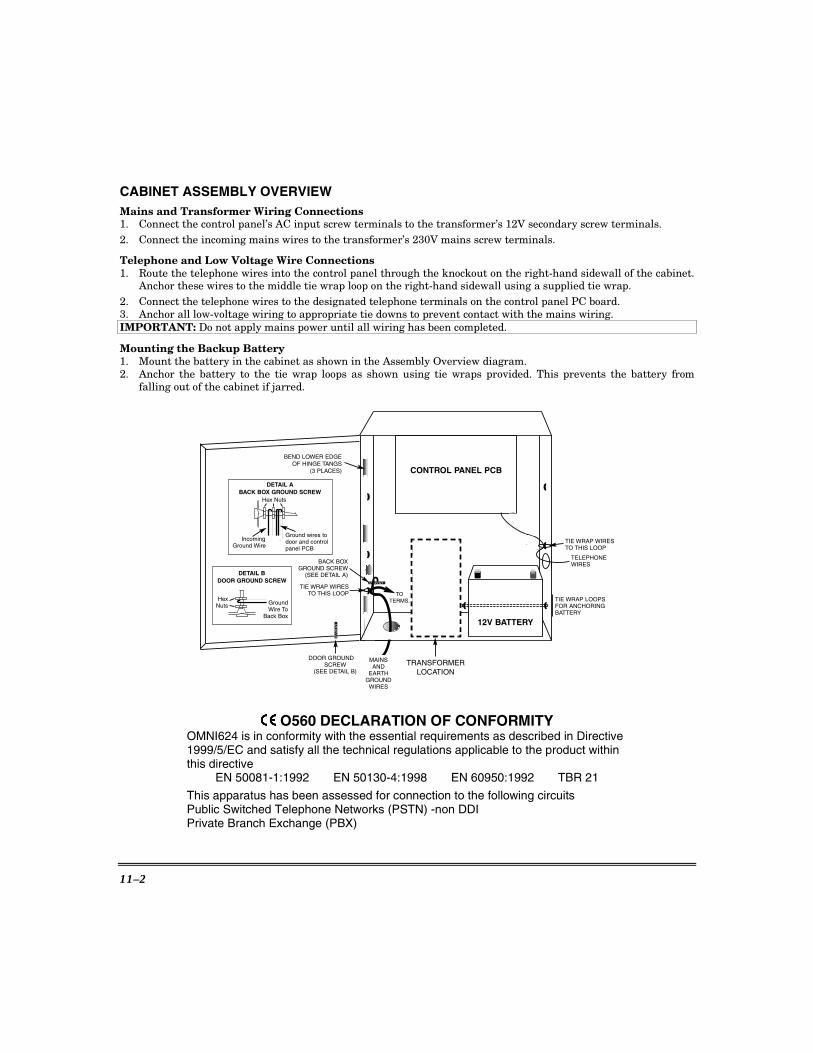
11–2
CABINET ASSEMBLY OVERVIEW Mains and Transformer Wiring Connections 1. Connect the control panel’s AC input screw terminals to the transformer’s 12V secondary screw terminals. 2. Connect the incoming mains wires to the transformer’s 230V mains screw terminals.
Telephone and Low Voltage Wire Connections 1. Route the telephone wires into the control panel through the knockout on the right-hand sidewall of the cabinet.
Anchor these wires to the middle tie wrap loop on the right-hand sidewall using a supplied tie wrap. 2. Connect the telephone wires to the designated telephone terminals on the control panel PC board. 3. Anchor all low-voltage wiring to appropriate tie downs to prevent contact with the mains wiring. IMPORTANT: Do not apply mains power until all wiring has been completed. Mounting the Backup Battery 1. Mount the battery in the cabinet as shown in the Assembly Overview diagram. 2. Anchor the battery to the tie wrap loops as shown using tie wraps provided. This prevents the battery from
falling out of the cabinet if jarred.
CONTROL PANEL PCB
TIE WRAP WIRESTO THIS LOOP
12V BATTERY
TELEPHONEWIRES
BEND LOWER EDGE OF HINGE TANGS
(3 PLACES)
TIE WRAP LOOPSFOR ANCHORINGBATTERY
BACK BOX GROUND SCREW
(SEE DETAIL A)
TIE WRAP WIRESTO THIS LOOP
DETAIL A
DETAIL B
BACK BOX GROUND SCREW
Ground wires todoor and controlpanel PCB
DOOR GROUND SCREW
GroundWire To
Back Box
Hex Nuts
Hex Nuts
IncomingGround Wire
DOOR GROUND SCREW
(SEE DETAIL B)
MAINS AND
EARTH GROUND
WIRES
TOTERMS.
TRANSFORMERLOCATION
O560 DECLARATION OF CONFORMITY OMNI624 is in conformity with the essential requirements as described in Directive 1999/5/EC and satisfy all the technical regulations applicable to the product within this directive
EN 50081-1:1992 EN 50130-4:1998 EN 60950:1992 TBR 21
This apparatus has been assessed for connection to the following circuits Public Switched Telephone Networks (PSTN) -non DDI Private Branch Exchange (PBX)

LIMITED WARRANTY
Honeywell International Inc., acting through its Security & Custom Electronics business ("Seller") 165 Eileen Way, Syosset, New York 11791, warrants its product(s) to be in conformance with its own plans and specifications and to be free from defects in materials and workmanship under normal use and service for 24 months from the date stamp control on the product(s) or, for product(s) not having a manufacturer’s date stamp, for 12 months from date of original purchase unless the installation instructions or catalog sets forth a shorter period, in which case the shorter period shall apply. Seller's obligation shall be limited to repairing or replacing, at its option, free of charge for materials or labor, any product(s) which is proved not in compliance with Seller's specifications or proves defective in materials or workmanship under normal use and service. Seller shall have no obligation under this Limited Warranty or otherwise if the product(s) is altered or improperly repaired or serviced by anyone other than Honeywell factory service. For warranty service, return product(s) transportation prepaid, to Honeywell Factory Service, 165 Eileen Way, Syosset, New York 11791.
THERE ARE NO WARRANTIES, EXPRESS OR IMPLIED, OF MERCHANTABILITY, OR FITNESS FOR A PARTICULAR PURPOSE OR OTHERWISE, WHICH EXTEND BEYOND THE DESCRIPTION ON THE FACE HEREOF. IN NO CASE SHALL SELLER BE LIABLE TO ANYONE FOR ANY CONSEQUENTIAL OR INCIDENTAL DAMAGES FOR BREACH OF THIS OR ANY OTHER WARRANTY, EXPRESS OR IMPLIED, OR UPON ANY OTHER BASIS OF LIABILITY WHATSOEVER, EVEN IF THE LOSS OR DAMAGE IS CAUSED BY THE SELLER'S OWN NEGLIGENCE OR FAULT. Seller does not represent that the product(s) it sells may not be compromised or circumvented; that the product(s) will prevent any personal injury or property loss by burglary, robbery, fire or otherwise; or that the product(s) will in all cases provide adequate warning or protection. Customer understands that a properly installed and maintained alarm system may only reduce the risk of a burglary, robbery, fire, or other events occurring without providing an alarm, but it is not insurance or a guarantee that such will not occur or that there will be no personal injury or property loss as a result. CONSEQUENTLY, SELLER SHALL HAVE NO LIABILITY FOR ANY PERSONAL INJURY, PROPERTY DAMAGE OR OTHER LOSS BASED ON A CLAIM THAT THE PRODUCT(S) FAILED TO GIVE WARNING. HOWEVER, IF SELLER IS HELD LIABLE, WHETHER DIRECTLY OR INDIRECTLY, FOR ANY LOSS OR DAMAGE ARISING UNDER THIS LIMITED WARRANTY OR OTHERWISE, REGARDLESS OF CAUSE OR ORIGIN, SELLER'S MAXIMUM LIABILITY SHALL NOT IN ANY CASE EXCEED THE PURCHASE PRICE OF THE PRODUCT(S), WHICH SHALL BE THE COMPLETE AND EXCLUSIVE REMEDY AGAINST SELLER.
This warranty replaces any previous warranties and is the only warranty made by Seller on this product(s). No increase or alteration, written or verbal, of the obligations of this Limited Warranty is authorized.

165 Eileen Way, Syosset, New York 11791Copyright © 2004 Honeywell International Inc.
www.honeywell.com/security
ÊN9967V3(Š N9967V3 4/04 Rev. A


