36
FC114 Digital Creasing & Numbering Machine Serial Number ___________________________ Date ___________________________________ 11/2014 Version 1
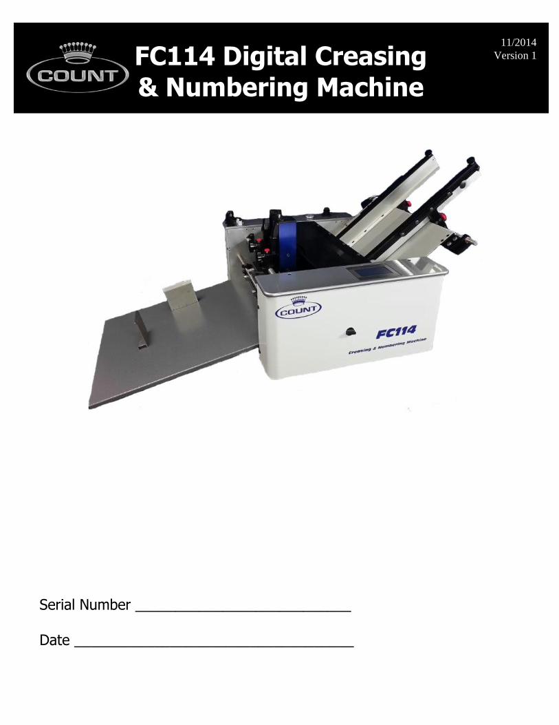
FC114 Digital Creasing & Numbering Machine
Serial Number ___________________________ Date ___________________________________
11/2014
Version 1

TABLE OF CONTENTS SPECIFICATIONS…………………………………………………………………………………………….1a SAFETY PROCEDURES/CARE & MAINTENANCE.………………………………………………….1b COMPONENT IDENTIFICATION…………………………………………………………………………2
SETTING UP YOUR FC114……………………………………………………………………….3
W/ Optional Stand………………………………………………………………………3 TOUCH SCREEN CONTROLLER ………………….………………………………………………….4
Perf Mode..........................……………………………………………….………5
Feeder Mode......................................…………………………….……..…6 Crease Mode...................………………………………………….…….…………6
Number Mode...................………………………………………….…….…………6 Programming for Number Mode..………..…………………...............................……….7
Transport Operation…………………………….……………………….……….……8 Programming for Crease Mode..………..…………………...............................……….8
Half Fold......................................................................................8
Tri-fold................................................................................………9 Z Fold.........................................................................................9 Letter Fold...................................................................................9 Roll Fold......................................................................................9
Gate Fold.....................................................................................10 Double Gate..................................................................................10 Double Parallel...............................................................................10 Perfect Bind Double Hinge...............................................................10
Perfect Bind Single Hinge...............................................................11 Perfect Bind No Hinge....................................................................11 Custom Crease Setups...................................................................11
Saving/Recalling Custom Jobs..........................................................12 Micro Adjusting the Crease Position...................................................12
Batch Counter..........…………………………………………………………………..13 DELIVERY TRAY ASSEMBLY…………………………………………………………………………….14
FEED TABLE ASSEMBLY……………………………………………………………………………….14 Component Identification…….…………………………………………………….14 Adjusting Feed Rails………..……………………………………………….………15
Setting the Automatic Feeder…………………………………………………….16 Fanning the Paper…………………………………………………………………….16 Loading the Feeder…………………………………………………………………..17 Replacing the Feed Wheels………………………………………………….……17
Feeding Notes…………………………………………………………………………17 Replacing the Friction Plate………………………………………………..……..18
Checking the Sensor…………………………………….…………………………..18
NUMBERING HEAD ............………………………………………………..….....................19 Head Parts..............…………………………………….………… …..20
Depressing a Wheel ...………………………………….…………………..21 Changing the Direction of the Head…..………….…………………….21
Adjusting the Vertical Bracket...…………………….… ……………..22 Adjusting for a Level Impression..……………… …………………..22
Tips For Leveling the Head....…………………………………………...23
Setting the Repeat Selector....………………………………………..23 Ink Cartridge........................…………………………...24
Perf Shaft & Strike Plate……………………………………................………25 Removing the Perf Shaft to Change Configurations………………………25
ROTARY PERF & SCORE ASSEMBLY………………………………………………………………..26 Component Identification………………………………………………………….26 Perforation & Scoring Assemblies……………………………………………….27 Gripper Wheel Perf Score Mounting……………………………………………27
Folding Direction of Paper…………………………………………………………27 RAC System (Rotary Actuated Creasing) Assembly……………………………………….28
Component Identification……………………………………………….………..28
Adjusting RAC rollers (depth of crease)……………………………………..29 Changing Lower Crease Die……………………………………………………...29
TROUBLESHOOTING………………………………………………………………………………………30-31
ELECTRICAL REQUIREMENTS AND SPECIFICATIONS
Power Requirement: 110/220V, 50-60 HZ, AC, Circuit Protection: 3 AMP Circuit Breaker
NOTE: Older buildings, overloaded lines, and bad grounds can affect the operation of your FC114. A dedicated line is best.
OPERATING SPEEDS
MODE TRANSPORT SPEED 8.5x11 Sheet(est) 5 ½” Sheet(est) (Feet per Sec.)
Perf Mode 2.5 12000 14000 Number Mode 2.0 8000 10000
Crease Mode 2.0 4500 5500
SPECIFICATIONS
Net Weight: FC114……………………………………………..250 lbs
Overall Dimensions: …………………………………………………………………32”Lx27”Wx26”D Min. Sheet Size: ………………………………………………………………..3”x5-7/8” Max. Sheet Size: …………………………………………………………………18”x20”-24”*
*NOTE: The FC114 is capable of handling many types of applications above and beyond
the standard specifications. It is possible to feed quite a variety of jobs, from 30” sheetsto die cut stocks. However, the performance of the FC114 on these special applicationsis directly related to the experience of the operator.
1a
SAFETY PROCEDURES
BEFORE USE:
Read through the owner’s manual. Follow instructions CAREFULLY. NEVER use a wet area. Electric shock could occur.
Use a GROUNDED outlet and a GROUNDED circuit. Do not use ungroundedequipment on the same circuit.
Always use a dedicated line. DO NOT use with line splitting surge protector.
DURING USE: Keep fingers and hands away from creasing bar, perf blades, and rubber rollers.
Keep cords clear of moving parts.
AFTER USE: Turn off machine at the rear panel, then unplug the main power cord. This will
prevent damage to your machine by power/voltage spikes. To unplug cords, always grasp the plug body, never pull on cords to disconnect. Wire
fatigue and possible shock could result from improper disconnect procedures.
BE ALERT! BE CAREFUL!
CARE AND MAINTENANCE
The FC114 is a precision machine. It is very important to keep it free of excessive dust, dirt and foreign matter. We recommend that you keep the machine covered when not in use.
BEARINGS: The FC114 uses 2 different style bearings sealed roller bearing and bronze
bushings. Sealed roller bearings and are designed to be self lubricating, however dirt and dust can get into them causing clogging and dirt build up. Bronze bushings need to be oiled on a regular basis. The bronze bushings on this machine are located on the operator side frame and
have the perf shaft and exit shaft through them. There are also 2 bushings located on the feed drive shaft. To oil these bronze bushings run the machine in feed mode and add a few drops of oil just inside the shaft collar that hold the shaft in place. Also add a few drops to the inside of
the machine so both sides of the bushing gets oil. It is recommended to occasionally oil the sealed roller bearings under heavy use.
STRIKE DIE: The groove in the lower die should be cleaned periodically using a toothbrush to remove any dirt or build up.
SENSOR EYE: Clean the lower reflector tape located on the base plate of the machine. Dust will cause the beam to not reflect correctly. Clean when necessary.
REMOVEABLE SCREWS: When these show signs of wear or stripping, replace as soon as possible. If these strip or hollow out they can be costly to remove. If you do keep your FC114 clean and in top condition, it will give you years of service.
1b
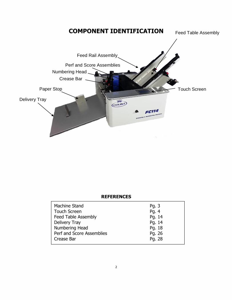
COMPONENT IDENTIFICATION
REFERENCES
2
Feed Table Assembly
Touch Screen
Delivery Tray
Perf and Score Assemblies
Crease Bar
Paper Stop
Machine Stand Pg. 3
Touch Screen Pg. 4 Feed Table Assembly Pg. 14
Delivery Tray Pg. 14 Numbering Head Pg. 18 Perf and Score Assemblies Pg. 26
Crease Bar Pg. 28
Feed Rail Assembly
Numbering Head
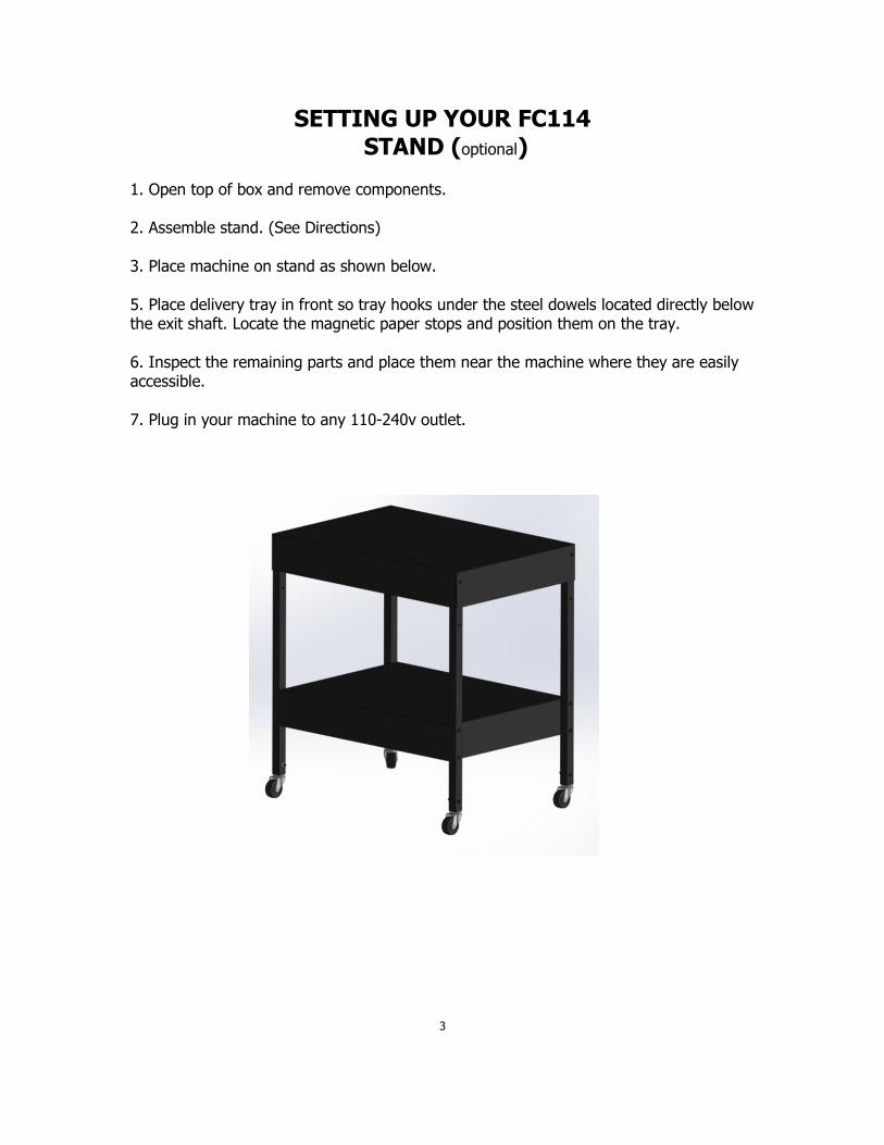
SETTING UP YOUR FC114 STAND (optional)
1. Open top of box and remove components.
2. Assemble stand. (See Directions)
3. Place machine on stand as shown below.
5. Place delivery tray in front so tray hooks under the steel dowels located directly belowthe exit shaft. Locate the magnetic paper stops and position them on the tray.
6. Inspect the remaining parts and place them near the machine where they are easilyaccessible.
7. Plug in your machine to any 110-240v outlet.
3
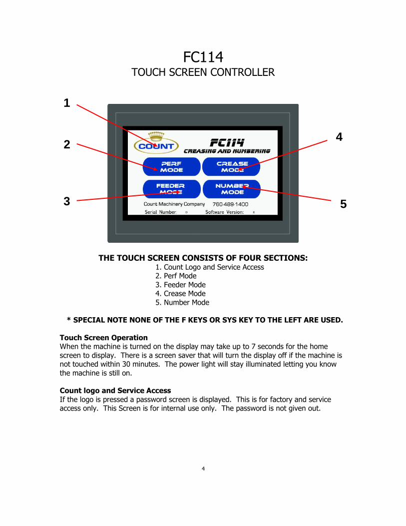
FC114 TOUCH SCREEN CONTROLLER
THE TOUCH SCREEN CONSISTS OF FOUR SECTIONS: 1. Count Logo and Service Access 2. Perf Mode
3. Feeder Mode 4. Crease Mode
5. Number Mode * SPECIAL NOTE NONE OF THE F KEYS OR SYS KEY TO THE LEFT ARE USED.
Touch Screen Operation When the machine is turned on the display may take up to 7 seconds for the home
screen to display. There is a screen saver that will turn the display off if the machine is not touched within 30 minutes. The power light will stay illuminated letting you know
the machine is still on. Count logo and Service Access
If the logo is pressed a password screen is displayed. This is for factory and service access only. This Screen is for internal use only. The password is not given out.
4
1
2
3
4
5
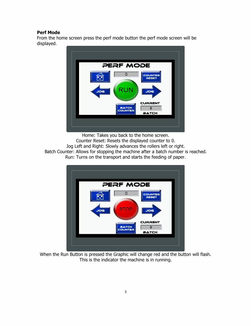
Perf Mode From the home screen press the perf mode button the perf mode screen will be
displayed.
Home: Takes you back to the home screen.
Counter Reset: Resets the displayed counter to 0.
Jog Left and Right: Slowly advances the rollers left or right. Batch Counter: Allows for stopping the machine after a batch number is reached.
Run: Turns on the transport and starts the feeding of paper.
When the Run Button is pressed the Graphic will change red and the button will flash.
This is the indicator the machine is in running.
5
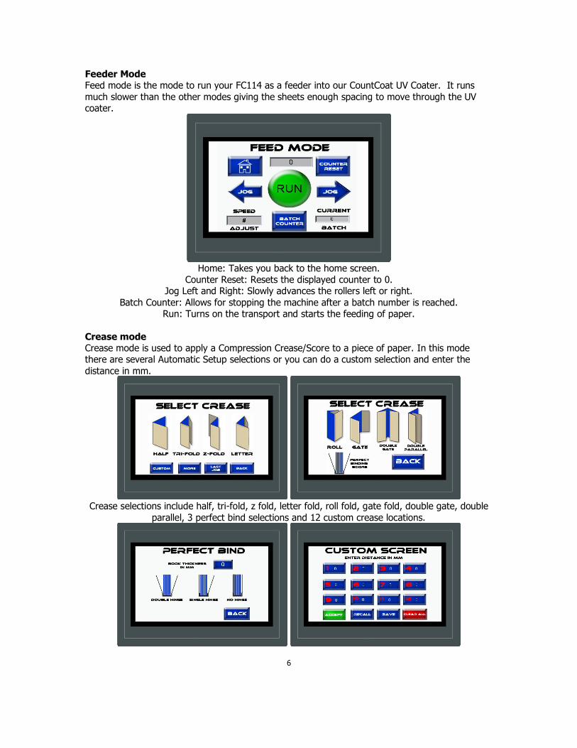
Feeder Mode Feed mode is the mode to run your FC114 as a feeder into our CountCoat UV Coater. It runs
much slower than the other modes giving the sheets enough spacing to move through the UV coater.
Home: Takes you back to the home screen. Counter Reset: Resets the displayed counter to 0.
Jog Left and Right: Slowly advances the rollers left or right.
Batch Counter: Allows for stopping the machine after a batch number is reached. Run: Turns on the transport and starts the feeding of paper.
Crease mode Crease mode is used to apply a Compression Crease/Score to a piece of paper. In this mode there are several Automatic Setup selections or you can do a custom selection and enter the
distance in mm.
Crease selections include half, tri-fold, z fold, letter fold, roll fold, gate fold, double gate, double
parallel, 3 perfect bind selections and 12 custom crease locations.
6

Number Mode Number mode is used to apply a numbering impression to a piece of paper. In this mode enter
the positions and what number head you would like to use for that position.
PROGRAMMING FOR NUMBER MODE
In Numbering Mode it is important to understand how to program the positions. The machine must be programmed in order from the lead edge of the sheet. Each Position
can fire Head 1, Head 2, or Both. If there are numbers in the positions already you must hit clear all and redo the programming.
Press the Number Mode Button > Positions > Clear All > 1 Position > Enter in Position > Select Head 1, 2, or Both > Accept > Run.
EXAMPLE:
7

TRANSPORT OPERATION
The Run Button will start the Transport in any given mode. Press it
again to stop the transport. Each Mode has a timeout feature to preserve the life of the machine.
A document may be slowly advanced through the transport by pushing and holding one of these buttons.
EXAMPLE:
The motor should advance transport at slow speed and stop whenever finger is lifted.
Controls on-off function of motor.
EXAMPLE:
Machine will run at mode and speed previously selected.
Machine will stop.
PROGRAMMING FOR CREASE MODE Half Fold: Press the Crease Mode Button > Half > Start Measuring > Physically Run a
sheet through the machine for the sensor to measure > Accept > Run.
EXAMPLE:
8
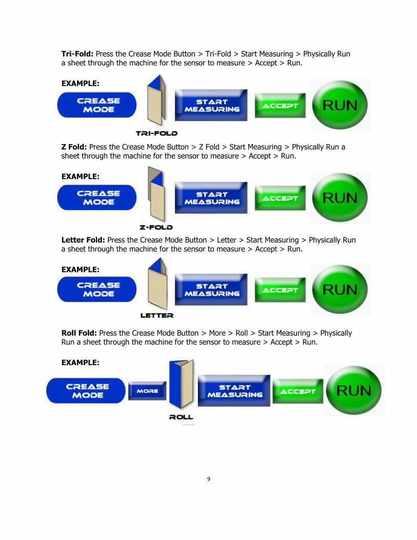
Tri-Fold: Press the Crease Mode Button > Tri-Fold > Start Measuring > Physically Run a sheet through the machine for the sensor to measure > Accept > Run.
EXAMPLE:
Z Fold: Press the Crease Mode Button > Z Fold > Start Measuring > Physically Run a sheet through the machine for the sensor to measure > Accept > Run.
EXAMPLE:
Letter Fold: Press the Crease Mode Button > Letter > Start Measuring > Physically Run a sheet through the machine for the sensor to measure > Accept > Run.
EXAMPLE:
Roll Fold: Press the Crease Mode Button > More > Roll > Start Measuring > Physically Run a sheet through the machine for the sensor to measure > Accept > Run.
EXAMPLE:
9

Gate Fold: Press the Crease Mode Button > More > Gate > Start Measuring >
Physically Run a sheet through the machine for the sensor to measure > Accept > Run.
EXAMPLE:
Double Gate Fold: Press the Crease Mode Button > More > Double Gate > Start
Measuring > Physically Run a sheet through the machine for the sensor to measure > Accept > Run.
EXAMPLE:
Double Parallel Fold: Press the Crease Mode Button > More > Double Parallel > Start Measuring > Physically Run a sheet through the machine for the sensor to measure > Accept > Run.
EXAMPLE:
Perfect Bind Double Hinge: Press the Crease Mode Button > More > Perfect Binding Score > Enter The Book Thickness > Double Hinge > Start Measuring > Physically Run a sheet through the machine for the sensor to measure > Accept > Run.
EXAMPLE:
10
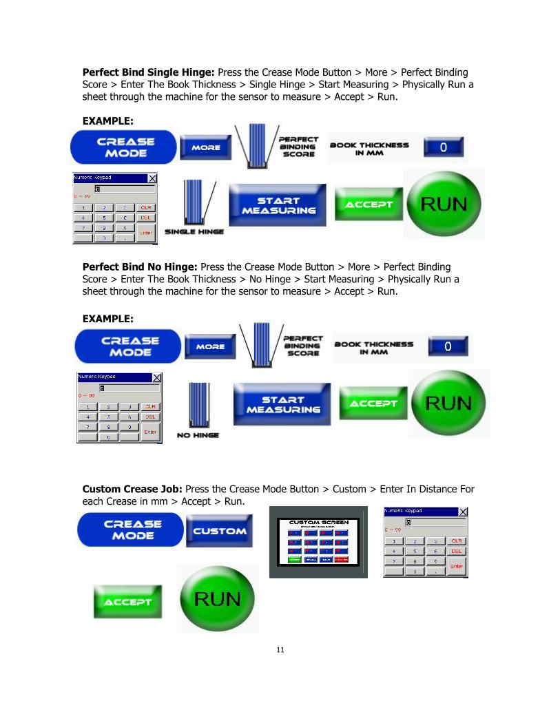
Perfect Bind Single Hinge: Press the Crease Mode Button > More > Perfect Binding Score > Enter The Book Thickness > Single Hinge > Start Measuring > Physically Run a
sheet through the machine for the sensor to measure > Accept > Run.
EXAMPLE:
Perfect Bind No Hinge: Press the Crease Mode Button > More > Perfect Binding
Score > Enter The Book Thickness > No Hinge > Start Measuring > Physically Run a sheet through the machine for the sensor to measure > Accept > Run.
EXAMPLE:
Custom Crease Job: Press the Crease Mode Button > Custom > Enter In Distance For
each Crease in mm > Accept > Run.
11
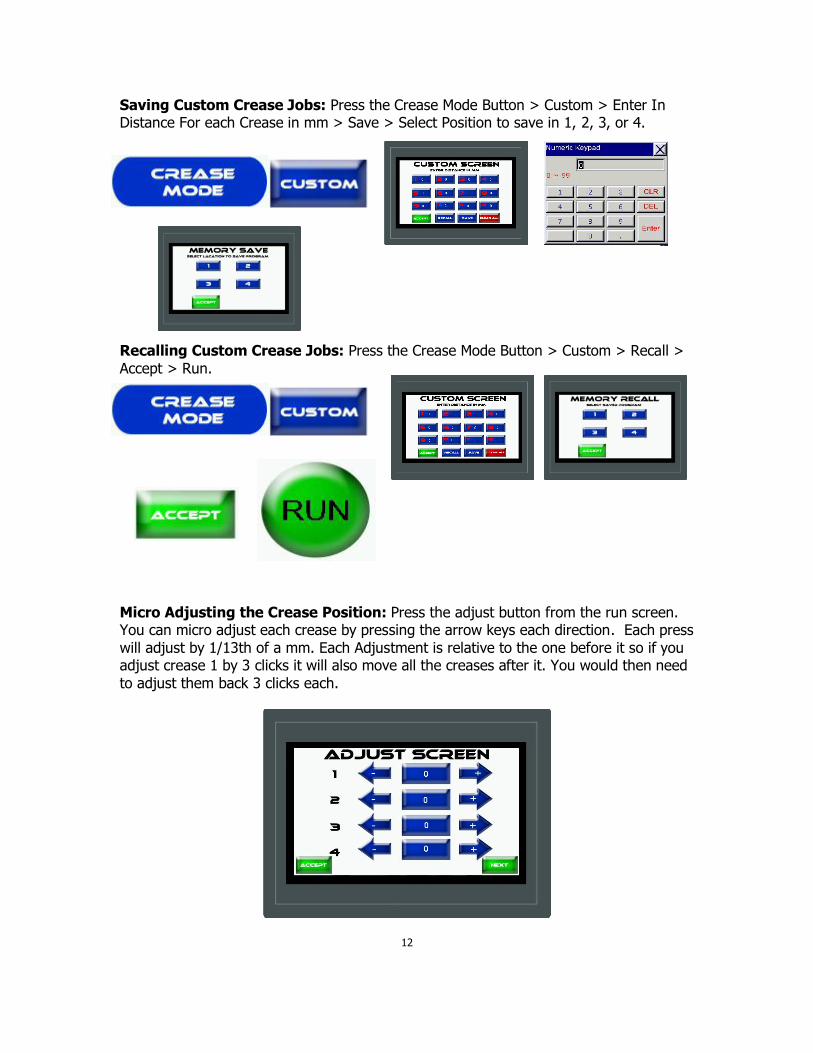
Saving Custom Crease Jobs: Press the Crease Mode Button > Custom > Enter In Distance For each Crease in mm > Save > Select Position to save in 1, 2, 3, or 4.
Recalling Custom Crease Jobs: Press the Crease Mode Button > Custom > Recall >
Accept > Run.
Micro Adjusting the Crease Position: Press the adjust button from the run screen. You can micro adjust each crease by pressing the arrow keys each direction. Each press
will adjust by 1/13th of a mm. Each Adjustment is relative to the one before it so if you adjust crease 1 by 3 clicks it will also move all the creases after it. You would then need
to adjust them back 3 clicks each.
12

Batch Counter: Press the Batch Counter button from the run screen in any mode and it will take you to the Batch Count Screen.
Press the Enter Batch Amount Button to enter in the number you want to run per batch.
Press the Reset Batch Button to start from 0. Press the On Button. The button turns red
as shown below.
As you are running and the batch number is reached the screen will display " Batch Complete.
13
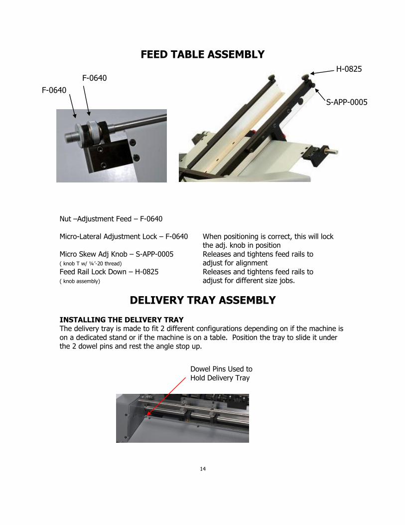
FEED TABLE ASSEMBLY
Nut –Adjustment Feed – F-0640
Micro-Lateral Adjustment Lock – F-0640 When positioning is correct, this will lock the adj. knob in position
Micro Skew Adj Knob – S-APP-0005 Releases and tightens feed rails to ( knob T w/ ¼’-20 thread) adjust for alignment
Feed Rail Lock Down – H-0825 Releases and tightens feed rails to ( knob assembly) adjust for different size jobs.
DELIVERY TRAY ASSEMBLY
INSTALLING THE DELIVERY TRAY The delivery tray is made to fit 2 different configurations depending on if the machine is
on a dedicated stand or if the machine is on a table. Position the tray to slide it under the 2 dowel pins and rest the angle stop up.
14
F-0640
F-0640
H-0825
S-APP-0005
Dowel Pins Used to
Hold Delivery Tray
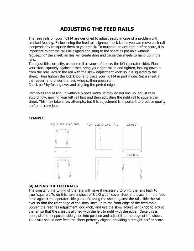
ADJUSTING THE FEED RAILS The feed rails on your FC114 are designed to adjust easily in case of a problem with
crooked feeding. By loosening the feed rail alignment lock knobs you can move each rail independently to square them to your stock. To maintain an accurate perf or score, it is important to get the rails as aligned and snug to the sheet as possible without
“squeezing” the sheet, as this will create drag and cause the sheets to hang up in the rails.
To adjust this correctly, use one rail as your reference, the left (operator side). Place your stock squarely against it then bring your right rail in and tighten, looking down it from the rear. Adjust the rail with the skew adjustment knob so it is squared to the
sheet. Then tighten the lock knob, and place your FC114 in perf mode. Set a sheet in the feeder, and under the feed wheels, then press run. Check perf by folding over and aligning the perfed edge.
Perf holes should line up within a blade’s width. If they do not line up, adjust rails
accordingly, moving your left rail first and then adjusting the right rail to square the sheet. This may take a few attempts, but this adjustment is important to produce quality perf and score jobs.
EXAMPLE:
SQUARING THE FEED RAILS The constant fine tuning of the rails will make it necessary to bring the rails back to
true “square”. To do this, take a sheet of 8 1/2 x 11” cover stock and place it in the feed table against the operator side guide. Pressing the sheet against the rail, slide the rail over so that the front edge of the stock lines up to the front edge of the feed table.
Loosen the feed rail adjustment lock knob, and use the skew adjustment knob to adjust the rail so that the sheet is aligned with the left to right with the edge. Once this is
done, slide the opposite side guide into position and adjust it to the edge of the sheet. Your rails should now feed the sheet perfectly aligned providing a straight perf or score.
15
SETTING THE AUTOMATIC FEEDER For efficient Auto-feeding, the setting of the feed wheels is very important. Use a piece of the stock to be run as a “feeler gauge”. Place a sheet under the feed wheels, turn the feed wheel adjustment screw
(counterclockwise to raise, clockwise to lower) so that the paper can slip freely under the wheels. The feed wheels should be barely touching the stock. If during the feeding you begin to get
doubles, lower the feed wheels just enough to stop the double sheeting. The paper between the friction plate and the auto feed wheel must move (fig.?)
freely and should not be gripped.
FANNING THE PAPER
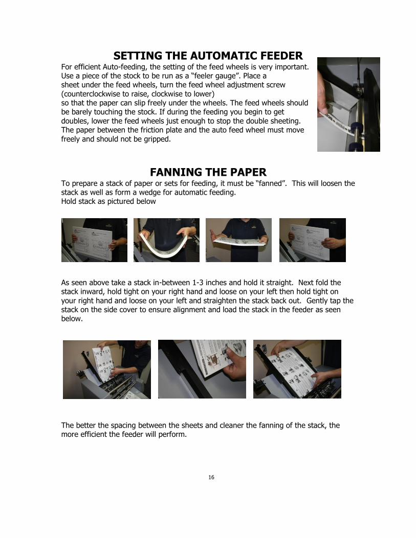
To prepare a stack of paper or sets for feeding, it must be “fanned”. This will loosen the stack as well as form a wedge for automatic feeding. Hold stack as pictured below
As seen above take a stack in-between 1-3 inches and hold it straight. Next fold the stack inward, hold tight on your right hand and loose on your left then hold tight on
your right hand and loose on your left and straighten the stack back out. Gently tap the stack on the side cover to ensure alignment and load the stack in the feeder as seen below.
The better the spacing between the sheets and cleaner the fanning of the stack, the more efficient the feeder will perform.
16
LOADING THE FEEDER
Take the fanned paper and load the feed tray as shown. The leading edge of the top sheet is slightly forward of the one below and so on throughout the stack. Tuck the lead edge of the stack under the feed wheels.
The feed wheels should be spaced evenly across the lead edge of the job to be run. These wheels are designed to easily slide on the shaft to the position necessary. Note: do not allow the machine to run with the feed wheels in contact with the friction
plate. This will cause the feed wheels to wear too quickly.
BACKFEEDING THE FEEDER Once your job is in progress, you can add paper to the feeder without stopping the transport. To add stock to the feeder while the unit is operating, fan a stack and while holding in your right hand, gently grasp the bottom set of the feeding stack with your
left. (insert pic here) Raise the back edge of the bottom set raising the back of the feeding stack, and slide the new stack under it. This procedure should be done while
there is still sufficient stock in the feeder to allow for the time needed to fan and insert the new stack.
FEEDING NOTES When set properly, the feed is very efficient and flexible. When neglected it can
become very frustrating to run even the simplest job. The adjustments
previously discussed are very important. The FC114 is capable of running 20lb. single sheets, 4 part forms and 100 lb
cover. It is also very capable of handling gloss, coated, and even laminated stocks. Its flexibility is directly related to the operator’s experience.
All carbonless sets are fed into the FC114 with as little pressure from the feed wheels as possible. Use just enough pressure to eliminate double feeding.
To clean the feed wheels, use only water on a clean cloth. Wipe the rollers in the direction of the ribbing while turning them by hand.
REPLACING THE FEED WHEELS
A top feed wheel is a replaceable part. After use it will develop wear and flatten out. This in itself is not bad. However, when the diameter of the wheel becomes too small, it will become difficult to adjust for consistent feed, and avoid feeding doubles.
Using the feed shaft height adjustment screws, raise the shaft so the feed wheels are not touching the friction plate. Loosen the inside shaft collars. Remove the non-operator
side cover and remove the pulley o-ring belt. Slide the shaft out about 6 to 8 inches. The old rollers can now be slid off and replaced with new feed rollers. Return the shaft into its bearing and reset the shaft collars leaving a slight bit of movement in the shaft.
The collars should not be tightened to cause any drag against the brass bushing.
17
REPLACING THE FRICTION PLATE The contact strip below the feed wheels is a consumable part. If this strip begins to show excessive wear, or additional pressure with the feed wheels does not stop double feeds from occurring, it may be time to replace the friction plate. To do so, begin by
removing all of the assemblies mounted on the perf assembly shaft. Use the T-handle wrench to remove the 2 flat head socket screws on each side of the friction plate. Once the screws are removed, slide the plate towards the front of the machine about 1
to 2 inches, lift the plate up on the contact strip side. With a smooth motion, slowly pull the friction plate up and out over the feed wheels, toward the back of the machine.
To put the new plate in, simply reverse the procedure of removing.
CHECKING THE SENSORS 1. Turn machine power on and allow screen to turn on 2. There should be 2 lights on the sensor a green indicating power is getting to the
sensor and orange that is the reflecting signal. If both light are not on there is a problem and must be fixed before you are able to run.
3. Make sure the sensor reflector tape is located on the base plate and the red beam from the sensor is hitting the tape. If not loosen the screws on the sensor and adjust the beam until it is on the tape.
4. If all above steps work correctly sensor is working properly, if not, contact the Count Machinery Company service department.
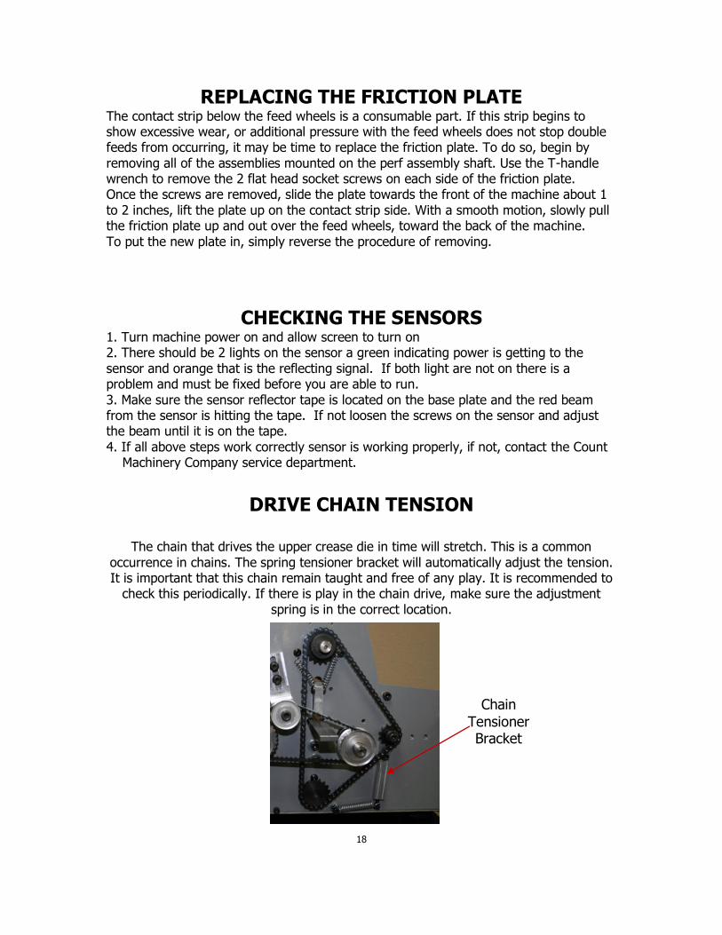
DRIVE CHAIN TENSION
The chain that drives the upper crease die in time will stretch. This is a common
occurrence in chains. The spring tensioner bracket will automatically adjust the tension. It is important that this chain remain taught and free of any play. It is recommended to
check this periodically. If there is play in the chain drive, make sure the adjustment
spring is in the correct location.
18
Chain
Tensioner Bracket
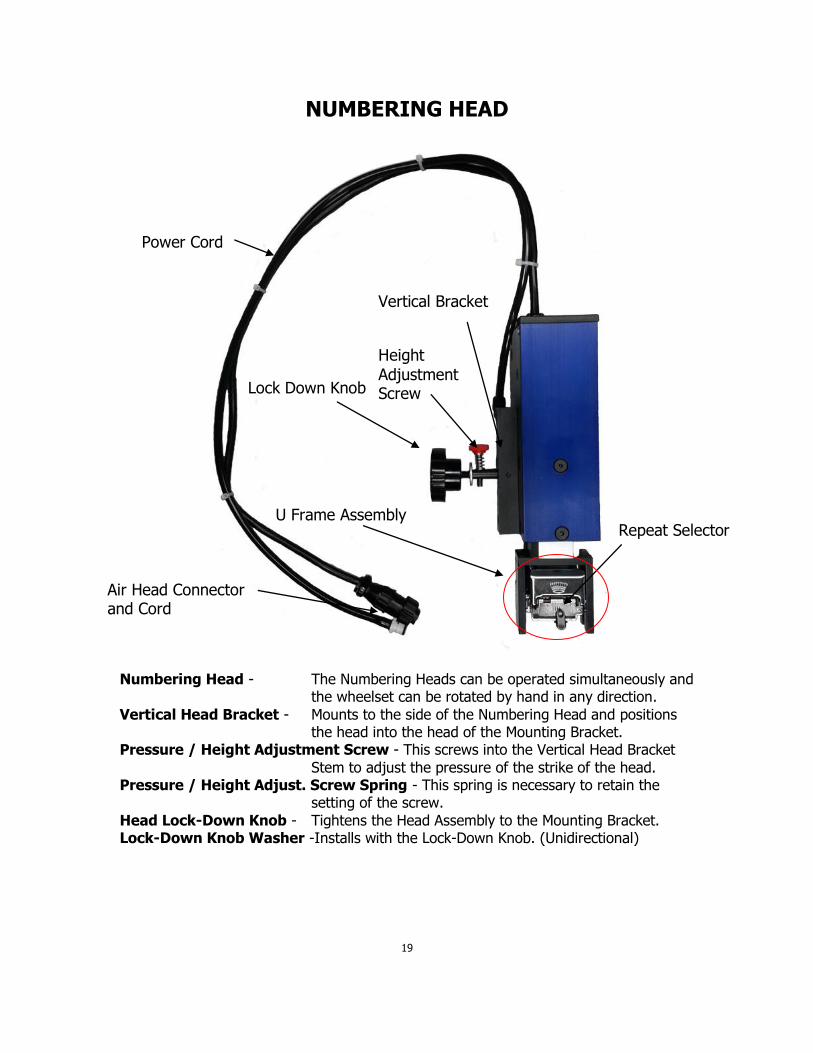
NUMBERING HEAD
Numbering Head - The Numbering Heads can be operated simultaneously and the wheelset can be rotated by hand in any direction.
Vertical Head Bracket - Mounts to the side of the Numbering Head and positions the head into the head of the Mounting Bracket.
Pressure / Height Adjustment Screw - This screws into the Vertical Head Bracket
Stem to adjust the pressure of the strike of the head. Pressure / Height Adjust. Screw Spring - This spring is necessary to retain the
setting of the screw.
Head Lock-Down Knob - Tightens the Head Assembly to the Mounting Bracket. Lock-Down Knob Washer -Installs with the Lock-Down Knob. (Unidirectional)
19
Repeat Selector
Power Cord
Vertical Bracket
Lock Down Knob
Height
Adjustment Screw
Air Head Connector and Cord
U Frame Assembly

Wheel Assembly Ink Swing Arm Repeat Selector C Clip
Repeat Selector Shaft Repeat Selector
Numbering Head Parts Numbers: Numbering Head - S-AAM-0921
Vertical Head Bracket - F-2696
Vertical Head Bracket Assy. - S-AAM-0801 Complete assembly includes: F-2696, H-
0475, H-0835, H-0575, S-AAM-0620, & 2x H-0225 screws
Pressure / Height Adjustment Screw - S-AAM-0620
Pressure / Height Adjust. Screw Spring - H-0575
Head Lock-Down Knob - H-0835
Lock-Down Knob Washer - H-0475
Power Cord - E-0974
Repeat Selector - S-AAM-0870
Wheel Assembly - H-1135
Swing Arm - S-UNS-0912
20
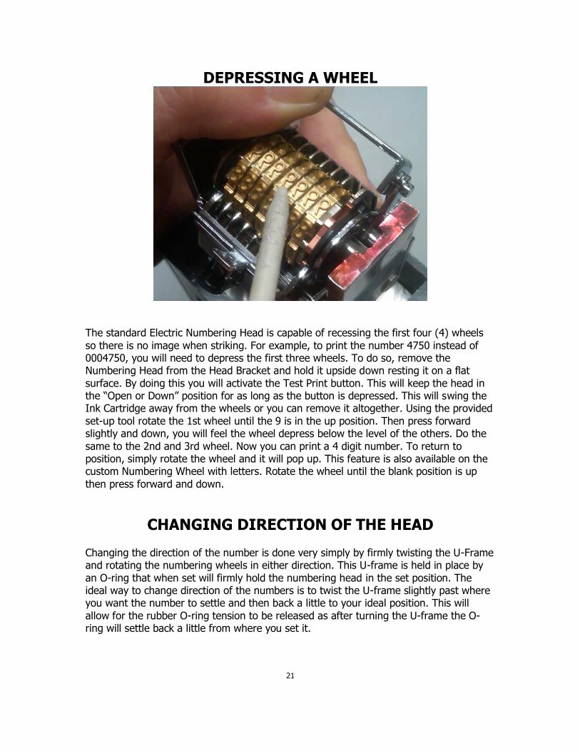
DEPRESSING A WHEEL
The standard Electric Numbering Head is capable of recessing the first four (4) wheels
so there is no image when striking. For example, to print the number 4750 instead of 0004750, you will need to depress the first three wheels. To do so, remove the Numbering Head from the Head Bracket and hold it upside down resting it on a flat
surface. By doing this you will activate the Test Print button. This will keep the head in the “Open or Down” position for as long as the button is depressed. This will swing the Ink Cartridge away from the wheels or you can remove it altogether. Using the provided
set-up tool rotate the 1st wheel until the 9 is in the up position. Then press forward slightly and down, you will feel the wheel depress below the level of the others. Do the
same to the 2nd and 3rd wheel. Now you can print a 4 digit number. To return to position, simply rotate the wheel and it will pop up. This feature is also available on the custom Numbering Wheel with letters. Rotate the wheel until the blank position is up
then press forward and down.
CHANGING DIRECTION OF THE HEAD Changing the direction of the number is done very simply by firmly twisting the U-Frame and rotating the numbering wheels in either direction. This U-frame is held in place by
an O-ring that when set will firmly hold the numbering head in the set position. The ideal way to change direction of the numbers is to twist the U-frame slightly past where you want the number to settle and then back a little to your ideal position. This will
allow for the rubber O-ring tension to be released as after turning the U-frame the O-ring will settle back a little from where you set it.
21
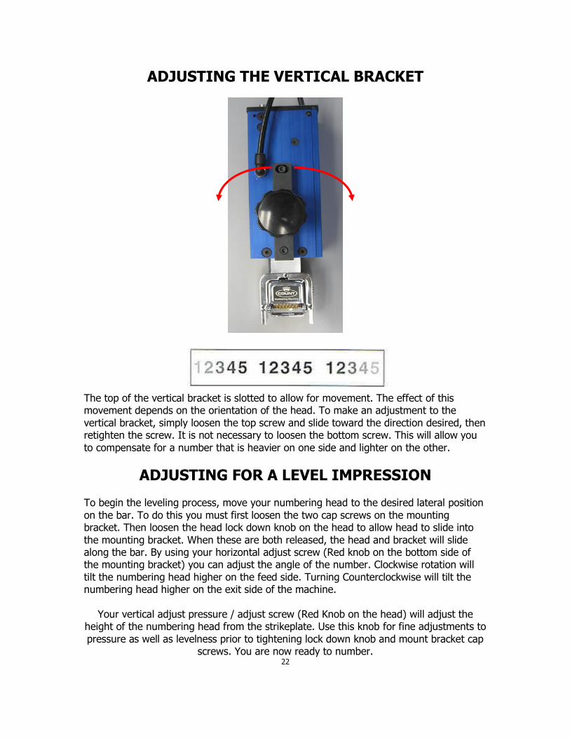
ADJUSTING THE VERTICAL BRACKET
The top of the vertical bracket is slotted to allow for movement. The effect of this movement depends on the orientation of the head. To make an adjustment to the
vertical bracket, simply loosen the top screw and slide toward the direction desired, then retighten the screw. It is not necessary to loosen the bottom screw. This will allow you
to compensate for a number that is heavier on one side and lighter on the other.
ADJUSTING FOR A LEVEL IMPRESSION To begin the leveling process, move your numbering head to the desired lateral position
on the bar. To do this you must first loosen the two cap screws on the mounting bracket. Then loosen the head lock down knob on the head to allow head to slide into
the mounting bracket. When these are both released, the head and bracket will slide along the bar. By using your horizontal adjust screw (Red knob on the bottom side of the mounting bracket) you can adjust the angle of the number. Clockwise rotation will
tilt the numbering head higher on the feed side. Turning Counterclockwise will tilt the numbering head higher on the exit side of the machine.
Your vertical adjust pressure / adjust screw (Red Knob on the head) will adjust the height of the numbering head from the strikeplate. Use this knob for fine adjustments to
pressure as well as levelness prior to tightening lock down knob and mount bracket cap screws. You are now ready to number.
22
TIPS FOR LEVELING HEAD
Leveling the numbering head is the most critical part of the set up process. If the head is not level you will get a blurred or “Ghosted” Impression. This can also occur when the
head is set to hit too lightly or too heavy. Never set pressure to favor the drop wheels, for this will depreciate the life of the numbering wheels.
The easiest way to check your impression is to use a 3 part carbonless set. Program the Auto Pro Plus to stamp in one location anywhere on the sheet. Run your test sheet
through the machine and check impression for pressure as well as levelness. By level we mean a level impression. Where the impression of the 1st digit is the same pressure and impression as the 5th and 6th digit and the top of the digits is the same as the bottom
you are level. We do not mean “plumb level,” as using a small level will not help.
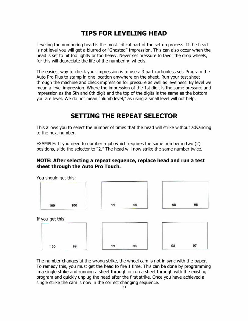
SETTING THE REPEAT SELECTOR
This allows you to select the number of times that the head will strike without advancing to the next number.
EXAMPLE: If you need to number a job which requires the same number in two (2) positions, slide the selector to “2.” The head will now strike the same number twice.
NOTE: After selecting a repeat sequence, replace head and run a test
sheet through the Auto Pro Touch. You should get this:
If you get this:
The number changes at the wrong strike, the wheel cam is not in sync with the paper.
To remedy this, you must get the head to fire 1 time. This can be done by programming in a single strike and running a sheet through or run a sheet through with the existing
program and quickly unplug the head after the first strike. Once you have achieved a single strike the cam is now in the correct changing sequence.
23

INK CARTRIDGE
The ink cartridge slides under the swing arm and locks into place. When installing a new ink cartridge, first remove the foam pad using an X-acto knife and place a small cut into
the reservoir. This will supply ink to the foam through the action of the swing arm. Start with a small hole as it is easier to make the hole larger, but if you start with the hole too large you cannot control the flow of the ink.
NOTE: The flow of ink can be sensitive to temperature. On a cold day
the ink will be thicker and not flow easily, whereas on a hot day the ink will be thin and flows faster. Also, be sure to shake cartridge well. We also suggest that when opening a new cartridge to use the piece of tape which holds the cover on to wrap around the cartridge about 1/4 of an inch. This will help
reduce excess ink on the numbering head especially when only using 3 or 4 digits where the foam would have a tendency to lift on the opposite side.
24
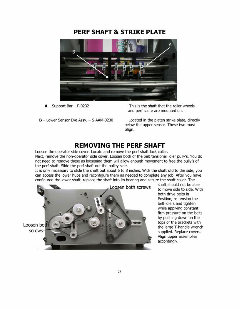
PERF SHAFT & STRIKE PLATE
A – Support Bar – F-0232 This is the shaft that the roller wheels and perf score are mounted on.
B – Lower Sensor Eye Assy. – S-AAM-0230 Located in the platen strike plate, directly below the upper sensor. These two must
align.
REMOVING THE PERF SHAFT Loosen the operator side cover. Locate and remove the perf shaft lock collar. Next, remove the non-operator side cover. Loosen both of the belt tensioner idler pully’s. You do
not need to remove these as loosening them will allow enough movement to free the pully’s of the perf shaft. Slide the perf shaft out the pulley side. It is only necessary to slide the shaft out about 6 to 8 inches. With the shaft slid to the side, you
can access the lower hubs and reconfigure them as needed to complete any job. After you have configured the lower shaft, replace the shaft into its bearing and secure the shaft collar. The
shaft should not be able
to move side to side. With both drive belts in
Position, re-tension the belt idlers and tighten while applying constant
firm pressure on the belts by pushing down on the tops of the brackets with
the large T-handle wrench supplied. Replace covers. Align upper assemblies
accordingly.
25
Loosen both screws
Loosen both
screws
A
B
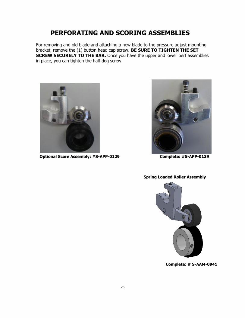
PERFORATING AND SCORING ASSEMBLIES
For removing and old blade and attaching a new blade to the pressure adjust mounting bracket, remove the (1) button head cap screw. BE SURE TO TIGHTEN THE SET
SCREW SECURELY TO THE BAR. Once you have the upper and lower perf assemblies in place, you can tighten the half dog screw.
Optional Score Assembly: #S-APP-0129 Complete: #S-APP-0139
26
Spring Loaded Roller Assembly
Complete: # S-AAM-0941
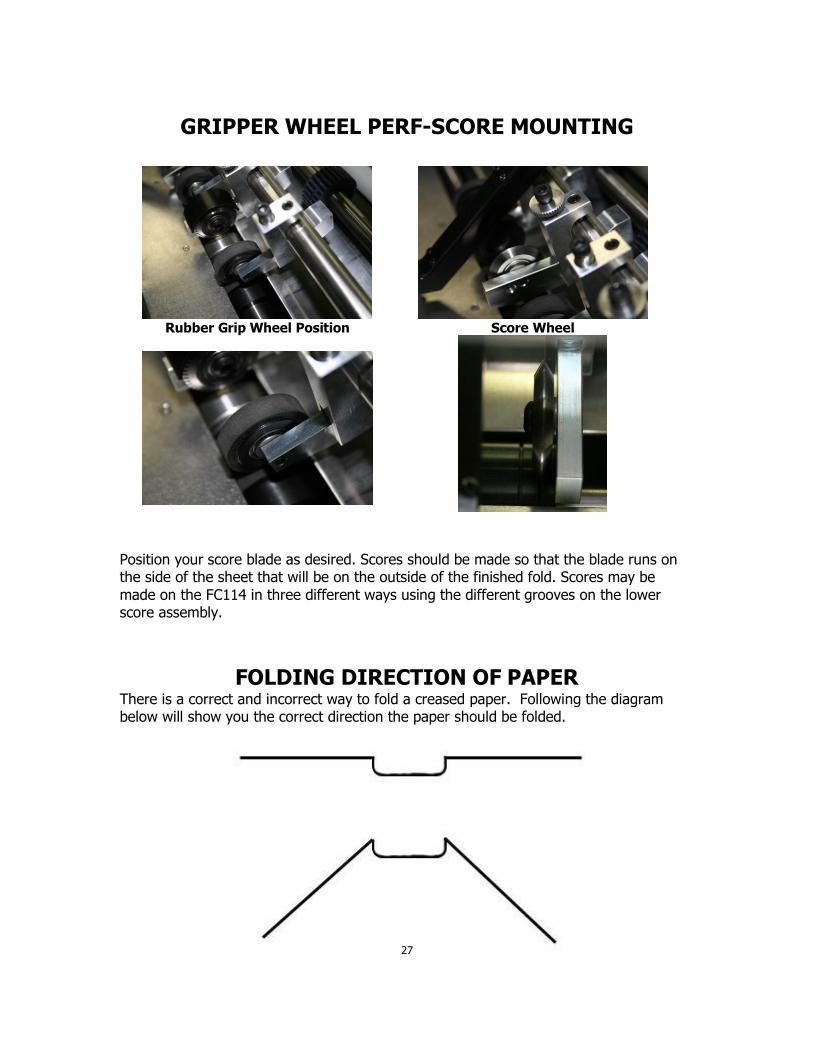
GRIPPER WHEEL PERF-SCORE MOUNTING
Position your score blade as desired. Scores should be made so that the blade runs on the side of the sheet that will be on the outside of the finished fold. Scores may be
made on the FC114 in three different ways using the different grooves on the lower score assembly.
FOLDING DIRECTION OF PAPER
There is a correct and incorrect way to fold a creased paper. Following the diagram below will show you the correct direction the paper should be folded.
27
Rubber Grip Wheel Position
Score Wheel
Use the master groove of the base ring to make scoring jobs with a standard mark over all types of paper stock.
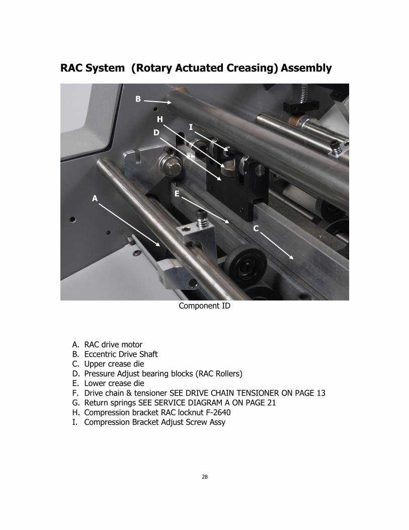
RAC System (Rotary Actuated Creasing) Assembly
Component ID
A. RAC drive motor B. Eccentric Drive Shaft C. Upper crease die
D. Pressure Adjust bearing blocks (RAC Rollers) E. Lower crease die
F. Drive chain & tensioner SEE DRIVE CHAIN TENSIONER ON PAGE 13 G. Return springs SEE SERVICE DIAGRAM A ON PAGE 21
H. Compression bracket RAC locknut F-2640 I. Compression Bracket Adjust Screw Assy
28
A
B
C
D
E
H I

ADJUSTING THE RAC ROLLERS
The RAC rollers are set from the factory and it is NOT recommended to make any adjustments to this without consulting with Count’s tech-support department. Should an adjustment be necessary, please follow the steps below.
Loosen the small bearing block lock screws. This allows very slight adjustments of the bearing block to be made by loosening the thumb lock and turning the height
adjustment screw in the middle of the bearing block. This is a very fine thread and is capable of making very slight adjustments. Turning the adjustment screw clockwise will increase the bar pressure, as counterclockwise will decrease the pressure. Once the
adjustment to the bar has been made, slightly tighten the thumb lock and re set the block set-screws.
ADJUSTING RAC TOP DEAD CENTER
The top dead center of the RAC will need to be adjusted from time to time. To do this
turn the machine off, remove the operator side cover, and manually rotate the eccentric shaft to the top dead center. Then locate the adjusting shaft collar on the end of the eccentric on the operators side and take a 5/32 allen wrench and loosen the button
head screw and rotate it to the 6 o’clock position. This will ensure proper alignment of the crease bar.
CHANGING THE LOWER CREASE DIE
The Lower crease die can easily be changed to accommodate thicker stocks by removing the non-operator side cover, slide the bar out and flip it over to use the wider die channel. Please note, custom die’s are available upon request.
29

TROUBLE SHOOTING
POWER DOES NOT TURN ON 1. Check circuit breaker on rear panel.
2. Check outlet for power. POWER TURNS ON BUT HMI DOES NOT LIGHT UP
1. Check 3 amp breaker on rear panel. 2. Make sure the green lights through the slots in the back panel are on. If not Check outlet power.
3. Check wiring to the plc and hmi. TRANSPORT “LOCKS UP” AFTER CREASING 1. Check pulleys to make sure they are securely tightened on shafts.
2. Check to see that the transport turns freely (oil when necessary). 3. Possible damage to microprocessor. FEED TABLE NOT FEEDING CORRECTLY
1. Clean feed wheel rollers. 2. Feed wheels do not have equal pressure on them, check adjustment.
3. Contact strip is worn and will not gap the stack. SHEETS NOT FEEDING STRAIGHT 1. Unequal feed wheel pressure.
2. Align feed rails “check for squareness”. This can be checked by the lead edge of the paper feeding into the machine should line up with the front edge of the feed plate.
3. Not enough pressure on forwarding rollers. 4. Clean ALL rubber rollers. PERF IS NOT STRAIGHT
1. Check for equal pressure on all grip wheels and that none are hanging up. 2. Recheck all steps under (SHEET NOT FEEDING STRAIGHT) PERFORATION IS NOT CLEAN OR CUTS SHEETS
1. Not enough pressure on perf wheel. 2. Perf blade is worn.
CREASE NOT REGISTERING ON SHEET 1. Clean all Rubber Rollers 2. Make sure to use a minimum of 4 entry and 2 exit gripper wheels on every
setup. 3. Check all pulleys to make sure they are securely tensioned on shafts. 4. Check to see that machine transport turns freely.
CREASE APPEARS WEAK 1. Crease bar not level.
2. Not enough pressure, adjust RAC rollers with height adjustment screw. 3. Too much pressure, motor cannot make full stroke. 4. Crease bar not tightened properly on bracket.
CREASE BAR DOES NOT ROTATE 1. Crease bar set too low, cannot make full stroke. 2. Crease bar is dirty. Clean with damp cloth and wipe clean.
3. Verify red light on creaser plc at Y4 is firing on and off. NUMBERS NOT REGISTERING ON SHEET:
1. Clean all rubber rollers. 2. Check pressure on grip wheels. If these are not down firmly your registration will be off. 3. Be sure paper guide bearings are not set in line with feed rails.
4. Check all pulleys to make sure are securely tightened to shafts. 5. Check to see that machine transport turns freely.
30

NUMBER APPEARS BLURRY:
1. Head is not level. See “leveling a head” page 21,22. 2. Not enough pressure, adjust with height adjustment screw.
3. Too much pressure, solenoid cannot make full stroke. 4. Head not tightened properly to head bracket. 5. Ink cartridge is empty or flow of ink is not consistent (TRY ROTATING THE INK PAD)
HEAD FIRES BUT NUMBER DOES NOT ADVANCE:
1. Head set too low cannot make full stroke
2. Possible damage or broken action indicator. 3. May need to send to headquarters for service.
NUMBERS TURN OUT OF SEQUENCE:
1. Head is dirty. Clean with Simple Green then oil with 3-1 oil.
2. Head is worn or damaged, contact COUNT service department.
31


251 Wedcor Avenue, Wabash, Indiana 46992 Website: www.countmachinery.com Email: [email protected]
Fax: (260) 563-4575
1/31/2017 Rev. 1M-S027964


