Set up FCoE Connectivity for a Cisco UCS Blade Document ID: 110434 Contents Introduction Prerequisites Requirements Components Used Network Diagram Conventions Background Information Main Task Task 1. Verify that Cisco UCS Fabric Interconnect Supports FCoE Feature 2. Identify Fiber Channel components and Connectivity in Cisco UCS 3. Create VSAN to Support FCoE for FC Uplink 4.1 Assign VSAN to FC Uplink Port in Fabric Interconnect 4.2 Assign VSAN to FC Uplink Port in Fabric Interconnect (Alternate Method) 5. Create vHBA within Server Profiles Verify Troubleshoot Related Information Introduction Cisco Unified Computing System (UCS) is a unified computing solution that fuses access layer networking and servers. This high-performance, next-generation server system provides the data center with a high degree of workload agility and scalability. The hardware and software components in the UCS support the unified fabric of Cisco, which allows multiple types of data center traffic over a single physical Ethernet network. This Data Center Ethernet (DCE) technology reduces the amount of cabling, management, and cost with the combination of the host bus adapters (HBAs) and network interface cards (NICs) into a single adapter called the Converged Network Adapter (CNA). This adapter can carry LAN and SAN traffic on the same cable. Cisco UCS uses Fibre Channel over Ethernet (FCoE) protocol to carry Fibre Channel (FC) traffic inside Ethernet frame. Cisco UCS also adheres to multiple 802.1 standards to provide the DCE underlying the FCoE needs to effectively transport those frames. The fabric interconnect separates the LAN and SAN traffic from the Ethernet frames and forwards them to the appropriate network ports. This gives the flexibility to deploy this technology without the need of implementing the unified fabric solution across the entire data center network. Cisco UCS blade installed with Cisco UCS CNA M71KR E Emulex Converged Network Adapter or Cisco UCS CNA M71KR Q QLogic Converged Network Adapter can handle both FC and IP simultaneously. The converged network adapter presents an Ethernet interface and an Fibre Channel interface to the operating system. The OS is completely unaware of the encapsulation taking place in the Ethernet segment. The only requirement is for the OS to have the appropriate drivers to recognize the CNA hardware. At the fabric interconnect, the server-facing Ethernet port receives the Ethernet and Fibre Channel traffic. The fabric interconnect (which uses Ethertype to differentiate the frames) separates the two traffic types. Ethernet frames and Fibre Channel frames are switched to their respective uplink interfaces.
Transcript
Set up FCoE Connectivity for a Cisco UCS Blade
Document ID: 110434
Contents
IntroductionPrerequisites Requirements Components Used Network Diagram ConventionsBackground InformationMain Task Task 1. Verify that Cisco UCS Fabric Interconnect Supports FCoE Feature 2. Identify Fiber Channel components and Connectivity in Cisco UCS 3. Create VSAN to Support FCoE for FC Uplink 4.1 Assign VSAN to FC Uplink Port in Fabric Interconnect 4.2 Assign VSAN to FC Uplink Port in Fabric Interconnect (Alternate Method) 5. Create vHBA within Server ProfilesVerifyTroubleshootRelated Information
Introduction
Cisco Unified Computing System (UCS) is a unified computing solution that fuses access layer networkingand servers. This high−performance, next−generation server system provides the data center with a highdegree of workload agility and scalability.
The hardware and software components in the UCS support the unified fabric of Cisco, which allows multipletypes of data center traffic over a single physical Ethernet network. This Data Center Ethernet (DCE)technology reduces the amount of cabling, management, and cost with the combination of the host busadapters (HBAs) and network interface cards (NICs) into a single adapter called the Converged NetworkAdapter (CNA). This adapter can carry LAN and SAN traffic on the same cable.
Cisco UCS uses Fibre Channel over Ethernet (FCoE) protocol to carry Fibre Channel (FC) traffic insideEthernet frame. Cisco UCS also adheres to multiple 802.1 standards to provide the DCE underlying the FCoEneeds to effectively transport those frames. The fabric interconnect separates the LAN and SAN traffic fromthe Ethernet frames and forwards them to the appropriate network ports. This gives the flexibility to deploythis technology without the need of implementing the unified fabric solution across the entire data centernetwork.
Cisco UCS blade installed with Cisco UCS CNA M71KR � E Emulex Converged Network Adapter or CiscoUCS CNA M71KR � Q QLogic Converged Network Adapter can handle both FC and IP simultaneously. Theconverged network adapter presents an Ethernet interface and an Fibre Channel interface to the operatingsystem. The OS is completely unaware of the encapsulation taking place in the Ethernet segment. The onlyrequirement is for the OS to have the appropriate drivers to recognize the CNA hardware.
At the fabric interconnect, the server−facing Ethernet port receives the Ethernet and Fibre Channel traffic. Thefabric interconnect (which uses Ethertype to differentiate the frames) separates the two traffic types. Ethernetframes and Fibre Channel frames are switched to their respective uplink interfaces.
This document illustrates all the necessary steps to properly configure FCoE connectivity for a Cisco UCSblade using either of the CNA's.
Prerequisites
Requirements
Cisco recommends that you:
Have a working knowledge of Cisco UCS Server Blade software and hardware.• Be familiar with the UCS Manager GUI.• Have a UCS system that runs version 1.0(1e) or later• Understand the impact and implications of the different commands described in this document• Be familiar with the UCS components and topology. Refer to the diagram for a typical solution.•
Ensure that you meet these requirements before you attempt this configuration:
Components Used
The information in this document is based on these software and hardware versions:
Cisco UCS System• Adaptor Cards required to support FCoE: the Cisco UCS CNA M71KR � E Emulex ConvergedNetwork Adapter or the Cisco UCS CNA M71KR � Q QLogic Converged Network Adapter
•
The information in this document was created from the devices in a specific lab environment. All of thedevices used in this document started with a default configuration. If your network is live, make sure that youunderstand the potential impact of any command.
Network Diagram
This is a typical topology used with the Cisco UCS:
This is the network diagram used in this test plan:
Conventions
Refer to the Cisco Technical Tips Conventions for more information on document conventions.
Background Information
The Cisco UCS follows the FCoE protocol as defined by the ANSI T11 Standards Committee. The FC trafficencapsulated inside this Ethernet requires the same lossless network characteristics that are found in a fabricnetwork. Instead of the buffer−to−buffer (B2B) credit system used in native fabric topologies, the FCoE relieson a new set of Ethernet standards that were develop to enhance the Ethernet protocol to ensure losslesstransport of the FCoE traffic.
The Ethernet links on the system support these Ethernet enhancements to ensure lossless transport for theFCoE traffic:
Priority Flow Control (PFC) IEEE 802.1Qbb is an extension of the PAUSE (802.3x) mechanism. PFCcreates eight virtual links in each physical link and allows any of these links to be paused individuallywithout affecting the flow of traffic in the other links.
•
Enhanced Transmission Selection (ETS) IEEE 802.1Qaz is a scheduling mechanism in hardware that•
allows a two−level Deficit Weighted Round Robin (DWRR) with strict priority support. This allowscontrol not only of bandwidth, but also of latency.Data Center Bridge eXchange (DCBX) is a discovery and capability exchange protocol to verify thatboth ends are configured properly to support the DCE traffic. It can provide basic configuration if oneof the two sides is not configured properly.
•
The fabric interconnect operates in N−Port Virtualization (NPV) mode and not as a FC switch in the fabric.This means that it does not require a FC domain ID to keep the number of domain IDs in the SAN fabric thesame. The fabric interconnect joins the fabric through a normal FLOGI. The FLOGIs that comes from theserver blade adapters is translated by the NPV process into FDISC into the fabric.
Main Task
Task
Before you begin, make sure that your upstream MDS switches are NPIV enabled, and assign the selectedinterface to the Cisco UCS with the appropriate VSAN number.
The Cisco UCS must be up and operational by now and have basic connectivity established.
1. Verify that Cisco UCS Fabric Interconnect Supports FCoE Feature
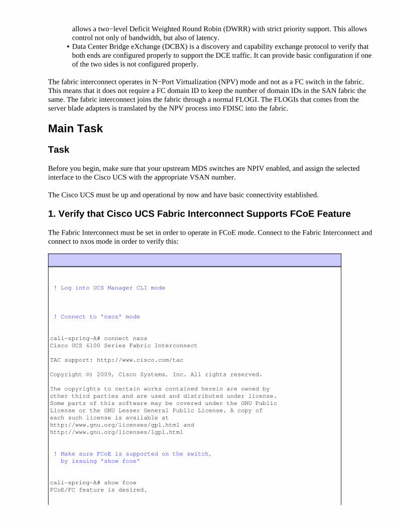
The Fabric Interconnect must be set in order to operate in FCoE mode. Connect to the Fabric Interconnect andconnect to nxos mode in order to verify this:
! Log into UCS Manager CLI mode
! Connect to "nxos" mode
cali−spring−A# connect nxosCisco UCS 6100 Series Fabric Interconnect
The copyrights to certain works contained herein are owned byother third parties and are used and distributed under license.Some parts of this software may be covered under the GNU PublicLicense or the GNU Lesser General Public License. A copy ofeach such license is available athttp://www.gnu.org/licenses/gpl.html andhttp://www.gnu.org/licenses/lgpl.html
! Make sure FCoE is supported on the switch, by issuing "show fcoe"
cali−spring−A# show fcoeFCoE/FC feature is desired.
Type �exit� to disconnect from nxos
Display of inventory will also show install of FC Modules into the switches
! exit from "nxos" mode to switch mode, and making sure you are seeing the FC module
cae−sj−ca−B# show fabric−interconnect inventory expandSwitch A:
Switch Card:
Slot Description Num Ports State PID Serial (SN) −−−−− −−−−−−−−−−−−−−−−−−−− −−−−−−−−−− −−−−−−−−−− −−−−−−−−−−−−−−− −−−−−−−−−−− 1 20x10GE/Supervisor 20 Online N10−S6100 JAF1242ASGK 2 8x1/2/4G FC Module 8 Online N10−E0080 JAB123800NM
2. Identify Fiber Channel components and Connectivity in Cisco UCS
Before you configure the fabric interconnect to support VSAN, you need to make sure that your FC uplinkexpansion works and is visible from the fabric interconnect. Complete these steps:
Log into UCS Manager GUI mode.1. In the Navigation pane, choose Equipment.2. Choose Fabric Interconnect > Fabric Interconnect #.3. Choose Uplink FC Ports.4.
3. Create VSAN to Support FCoE for FC Uplink
The FC port defaults to VSAN 1 in Cisco UCS, but, if the upstream Fibre Channel switch is connected to adifferent VSAN #, the proper VSAN configuration is required on the FC ports of the Fabric Interconnect.Complete these steps:
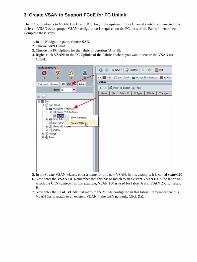
In the Navigation pane, choose SAN.1. Choose SAN Cloud.2. Choose the FC Uplinks for the fabric in question (A or B).3. Right−click VSANs in the FC Uplinks of the Fabric # where you want to create the VSAN forUplink.
4.
In the Create VSAN wizard, enter a name for this new VSAN. In this example, it is called vsan−100.5. Now enter the VSAN ID. Remember that this has to match to an existent VSAN ID in the fabric towhich the UCS connects. In this example, VSAN 100 is used for fabric A and VSAN 200 for fabricB.
6.
Now enter the FCoE VLAN that maps to the VSAN configured in this fabric. Remember that thisVLAN has to match to an existent VLAN in the LAN network. Click OK.
7.
Click the VSAN name you created in order to display your results.
Now, repeat the same process for the uplink of Fabric B, except with VSAN 200 and VLAN 200 forFabric B, you get this result:
8.
4.1 Assign VSAN to FC Uplink Port in Fabric Interconnect
Now assign the VSAN you just created to the FC Uplink port in your Fabric Interconnect that has a direct linkto your SAN network. Complete these steps:
In the Navigation pane, choose the Equipment tab.1. Choose Fabric Interconnect A > Expansion Module #.2. Choose Uplink FC Ports and choose the FC Port 1 that has a connection to the upstream SANswitch.
3.
In the Work pane to the right in VSAN, choose the VSAN you just created from the drop−downmenu.
4.
Click Save Changes.
Repeat the same process to assign this VSAN to all the designated FC Up link ports that remain onthis same Fabric Interconnect.
5.
In order to configure the second fabric, repeat steps 2 through 5. Cisco recommends that you use adifferent VSAN and a different FCoE VLAN to keep your fabrics separated. In this example, VSANID 200 and FCoE VLAN 200 were used.
6.
4.2 Assign VSAN to FC Uplink Port in Fabric Interconnect (AlternateMethod)
Choose the FC port linked to your SAN network and assign this port to the VSAN created in the previousstep.
These FC Uplinks must already be provisioned with respective VSAN IDs on the SAN network side (MDSswitch).
In the Navigation pane, choose the SAN tab.1. Expand SAN Cloud and then expand FC Uplinks − Fabric A.2. Expand Uplink FC Ports. In this test case, choose FC Port 2/1 that has connection to the upstreamSAN switch.
3.
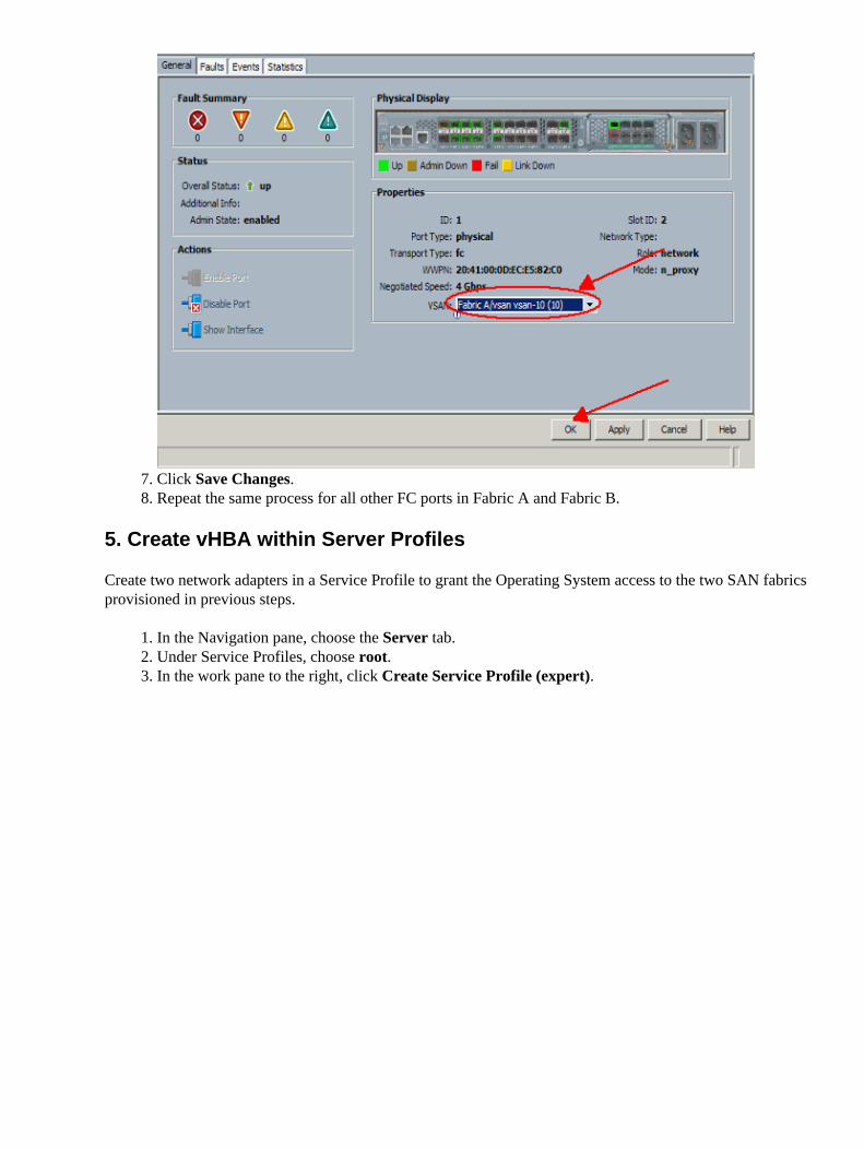
Either right−click the desired FC port, or, in the Work pane to the right, click the port as shown.4.
In the Properties pop−up window for FC Port 1, choose the VSAN to which this FC port will pinnedfrom the drop−down menu.
5.
Click OK.6.
Click Save Changes.7. Repeat the same process for all other FC ports in Fabric A and Fabric B.8.
5. Create vHBA within Server Profiles
Create two network adapters in a Service Profile to grant the Operating System access to the two SAN fabricsprovisioned in previous steps.
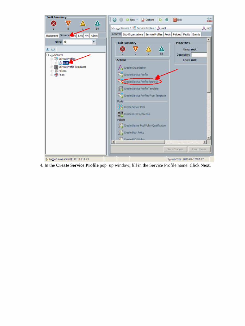
In the Navigation pane, choose the Server tab.1. Under Service Profiles, choose root.2. In the work pane to the right, click Create Service Profile (expert).3.
In the Create Service Profile pop−up window, fill in the Service Profile name. Click Next.4.
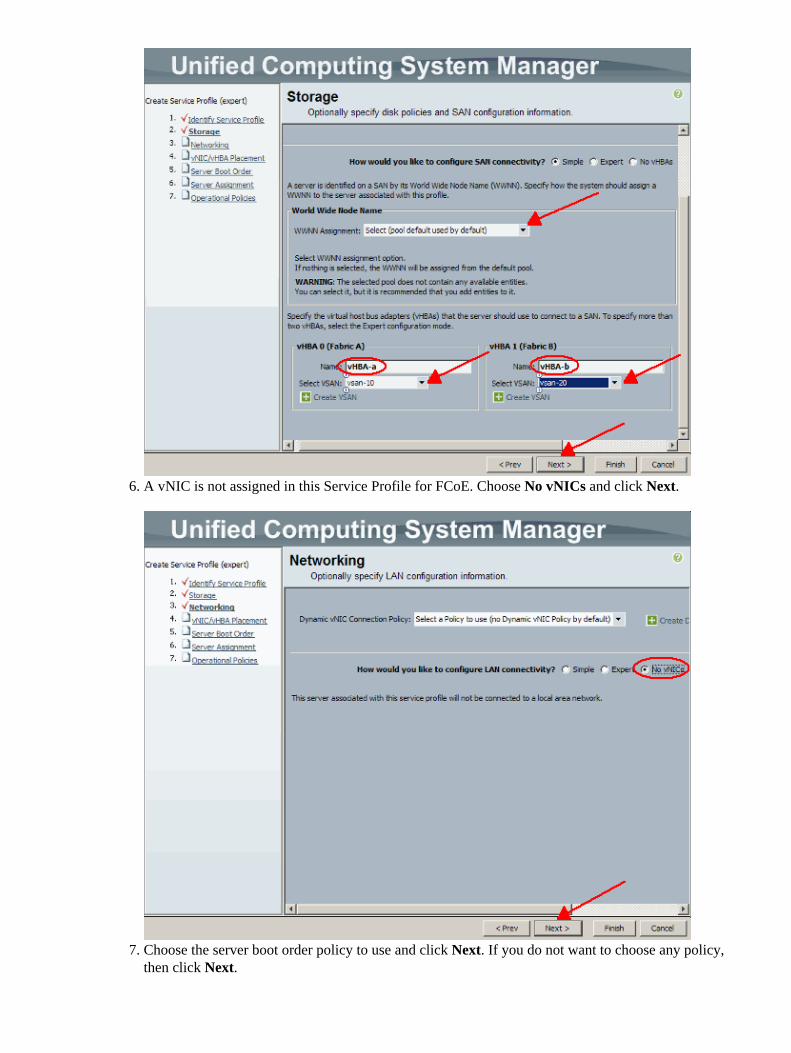
In Storage section, add the vHBAs that you have just configured on Fabric Interconnect A and B. Youcan also give a name to these vHBA's. Make sure that you have selected the correct WWNN pool forthese vHBAs.
5.
A vNIC is not assigned in this Service Profile for FCoE. Choose No vNICs and click Next.6.
Choose the server boot order policy to use and click Next. If you do not want to choose any policy,then click Next.
7.
In the Server Assignment window, choose the server pool to use and click Next. If you do not want tochoose a server pool now, click Next.
8.
Choose the IPMI profile and the SoL Configuration profile that you wnat to apply to this policy andclick Finish. If you do not want to apply and IPMI or SoL profile, then click Finish.
9.
The results are successful.
The created vHBAs are visible in the vHBA tab of your created profile.
10.
Verify
Refer to the verification process in the previous section.
Troubleshoot
There is currently no specific troubleshooting information available for this configuration.
Related Information
Technical Support & Documentation − Cisco Systems•


![Oracle VM Server for SPARC 3.3 Reference Manual · ldm set-vhba timeout=seconds vHBA-name domain-name ldm add-vsan [-q] iport-path vSAN-name domain-name ldm remove-vsan vSAN-name](https://static.documents.pub/doc/80x56/5f98fbe69e2b5815e22b3dd2/oracle-vm-server-for-sparc-33-reference-manual-ldm-set-vhba-timeoutseconds-vhba-name.jpg)


