32
Power Flame Incorporated Power Flame Incorporated ® FD & FDM Installation and Operation Manual Installation and Operation Manual FD & FDM

Power Flame IncorporatedPower Flame Incorporated
DC4 DRAFT CONTROL
ENTERESC
®
FD & FDMInstallation and
Operation ManualInstallation and
Operation Manual
FD & FDMDC4 DRAFT CONTROL
ENTERESC
®®
Power Flame®

PPOOWWEERR FFLLAAMMEE MMOODDEELL FFDD//FFDDMM BBUURRNNEERR For use by Qualified Service Personnel Only
WARNING
The improper installation, adjustment, alteration, service or maintenance of this equipment can result in fire, explosion, serious injury, or death.
Refer to this manual. For assistance or additional information consult a qualified installer, service agency or the gas supplier.
Do not store or use gasoline or any other flammable liquids in the vicinity of this or any other appliance.
ATTENTION! All Personnel involved with the startup, maintenance, or adjustment of this burner must
read and understand the entire contents of this manual prior to any startup or adjustment made to the burner and related components. Installation and service must be performed
by a qualified installer, service agency or the gas supplier.
WHAT TO DO IF YOU SMELL GAS
1. Do not try to light any appliance 2. Do not touch any electrical switch 3. Do not use any phone in your building 4. Immediately call your gas supplier from a neighbor’s phone 5. Follow the gas supplier’s instructions 6. If you cannot reach your gas supplier, call the fire department
FD & FDM Installation & Operation Manual - POWER FLAME INCORPORATED
1. GENERAL PRODUCT INFORMATION ............................................................................................... 1.1 PRINCIPLE OF OPERATION................................................................................................................... 1.2 MODEL IDENTIFICATION.................................................................................................................... 1.3 CAPACITIES & SPECIFICATIONS ......................................................................................................... 1.4 WARRANTY AND SPARE PARTS INFORMATION ....................................................................................
2. INSTALLATION ................................................................................................................................... 2.1 BURNER MOUNTING: GENERAL ........................................................................................................ 2.2 GAS PIPING .............................................................................................................................. 2.3 WIRING ...............................................................................................................................
3. START UP PROCEDURES ................................................................................................................. 3.1 SERVICE TEST EQUIPMENT REQUIRED................................................................................................ 3.2 GENERAL START-UP.......................................................................................................................
4. PARTS LIST..................................................................................................................... .................. 4.1 FD PARTS LIST............................................................................................................................... 4.2 FDM PARTS LIST .........................................................................................................................
5. MAINTENANCE................................................................................................................................. 5.1 GENERAL INFORMATION ............................................................................................................... 5.2 PERIODIC CHECK LIST......................................................................................................................
6. BURNER START UP INFORMATION & TEST DATA.......................................................................
7. OWNER OPERATING INSTRUCTIONS.............................................................................................
®
11122
3346
668
12
1217
222223
24
26

FD & FDM Installation & Operation Manual - POWER FLAME INCORPORATED
4
11.. GGEENNEERRAALL PPRROODDUUCCTT IINNFFOORRMMAATTIIOONN
11..11 PPrriinncciippllee ooff ooppeerraattiioonn
1.1.1 The Type FD/FDM burner is designed for high turndown operation firing into heat exchangers for air handling applications or directly into process air streams such as ovens and similar lower temperature industrial applications. The capacity range of the burner is from 30 to 3,500 MBH using natural or propane gas. Input ratings are based on 0.0” w.c. combustion chamber conditions.
1.1.2 The Type FD burner has a fixed air inlet and is designed to fire directly into an air stream for a wide range of heating applications with a 30:1 turndown. The Type FDM burner is fitted with moveable air dampers to the inlet of the blower assembly that allows on-ratio control over a 20:1 turndown range. The Type FDM is particularly well suited for indirect fired units requiring high turndowns. The Type FDM burner can also be applied on direct fired applications where on-ratio control may be required.
1.1.3 The complete packaged burner consists of the firing head with gas dispersion manifold, blower housing, control box with primary safety control and modulating air damper. Accommodation for an extended combustion tube (see Section 2.1.5) is also provided.
11..22 MMooddeell IIddeennttiiffiiccaattiioonn
225FD
Burner rate (2.250 MBH)
M
Modulation
Burner name FD
®
1

FD & FDM Installation & Operation Manual - POWER FLAME INCORPORATED
5
11..33 CCAAPPAACCIITTIIEESS && SSPPEECCIIFFIICCAATTIIOONNSS
Model Number ** FD/FDM75 FD/FDM150 FD/FDM225 FD/FDM250 FD/FDM300 FD/FDM350
Max Rate (MBH) 750 1500 2250 2500 3000 3500
Min Rate (MBH)Type FD 30 50 75 80 90 105
Min Rate (MBH)Type FDM 38 75 113 125 150 175
Blower Wheel SizeType FD 5 1 /16 x 1 1 /2 5 3 /4 x 1 1 /2 5 3 /4 x 2 1 /2 5 3 /4 x 3 5 3 /4 x 3 1 /2 5 3 /4 x 3 1 /2
Blower Wheel SizeType FDM 5 1 /16 x 1 1 /2 6 1 /4 x 3 7 x 3 7 x 3 7 5 /8 x 3 7 5 /8 x 3 1 /2
Blower Motor (HP) 1 /4 1 /3
1 /2 3 /4 1 1 1 /2
Manifold Pressure *Natural Gas (" wc) 2.8 1.9 2.1 2.3 2.9 4.0
Manifold Pressure *Propane (" wc) 5.6 4.3 4.1 4.1 3.8 7.5
Turndown Ratio (FD/FDM) 30/20 30/20 30/20 30/20 30/20 30/20
Table 1: specification FD and FDM burners
* To achieve maximum rating against 0.0” w.c. chamber pressure
** Model FDMR also includes data in table and the “R” indicates that the burner is mounted in the inverted position i.e. the fan housing is located above the burner blast tube centerline versus below the blast tube centerline.
11..44 WWaarrrraannttyy aanndd SSppaarree PPaarrttss IInnffoorrmmaattiioonn
1.4.1 Power Flame offers a 15 month Limited Warranty on all components from the date of shipment (see inside of back cover for details).
1.4.2 The Owners Information envelope packed with the burner contains a Warranty Registration Card. The Warranty Registration Card is also a request form for a computer generated Spare Parts List. An on-hand supply of spare parts is highly recommended in case of emergency shutdown. The pre-addressed, postage paid Warranty Registration Card should be completed and returned to Power Flame. In the event that the Warranty Registration Card is lost, please contact Power Flame’s Customer Service Department in Parsons, Kansas or you may register on-line through the Power Flame website (www.powerflame.com). All communications with the factory will be handled more efficiently if the burner is identified by the burner model, serial and job numbers. This information is stamped into the burner nameplate that is attached to the integral control panel (or to the burner, when remote control panels are supplied).
®
2
FD & FDM Installation & Operation Manual - POWER FLAME INCORPORATED
6
22.. IINNSSTTAALLLLAATTIIOONN
22..11 BBuurrnneerr MMoouunnttiinngg:: GGeenneerraall
2.1.1 Before beginning installation, carefully study these instructions and all charts, drawings and diagrams shipped with the burner.
2.1.2 Installation must be in accordance with all local and national codes. In the State of Massachusetts installation of the burner must comply with the regulations as stated in the Commonwealth of Massachusetts #248CMR 6.8.3.
2.1.3 The FD/FDM burner is designed to fire into a heating/combustion chamber or heat exchanger that is at negative, atmospheric or slightly positive pressure. Consult the factory if the combustion chamber or heat exchanger pressure is greater than 0.3” w.c. positive or 2.0” w.c. negative, as special precautions may be required.
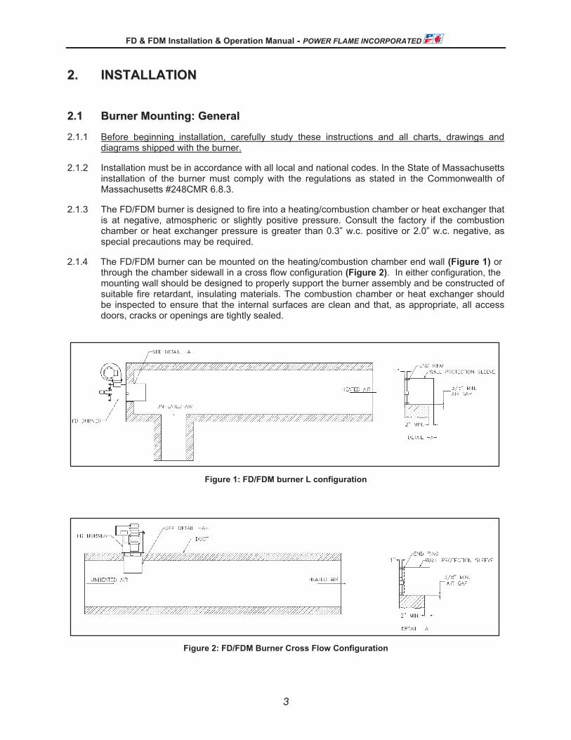
2.1.4 The FD/FDM burner can be mounted on the heating/combustion chamber end wall (Figure 1) or through the chamber sidewall in a cross flow configuration (Figure 2). In either configuration, the mounting wall should be designed to properly support the burner assembly and be constructed of suitable fire retardant, insulating materials. The combustion chamber or heat exchanger should be inspected to ensure that the internal surfaces are clean and that, as appropriate, all access doors, cracks or openings are tightly sealed.
Figure 1: FD/FDM burner L configuration
Figure 2: FD/FDM Burner Cross Flow Configuration
®
3

FD & FDM Installation & Operation Manual - POWER FLAME INCORPORATED
7
2.1.5 The standard burner insertion depth into the heating/combustion chamber sidewall is 2”. If there is any concern relating to potential flame impingement on the side or end wall insulation jacket the optional extended combustion tube should be used. The FDM burner is also available with a 4” insertion depth to fit many of today’s current heat exchanger designs.
2.1.6 For direct fired, cross flow configurations, the FD or FDM burner assembly should be fitted with the extended combustion tube that extends through the combustion chamber wall and into the process air stream (see Figure 2). The extended combustion tube is constructed from stainless steel and is designed to shield the flame from cross flow air or products of combustion that exceed 20 ft/sec.
2.1.7 Horizontal mounted burner assemblies are designed to withstand high temperatures from hot air blowing back during normal shutdown. Down fired or roof mounted burners may be subjected to higher temperatures during shutdown from the air flowing up through the burner. It may be necessary to mount the fan remote from the burner and connect via ducting.
2.1.8 Bolt the burner assembly rigidly onto the combustion chamber or heat exchanger front wall as shown in Figures 1 and 2. It is important to achieve a tight seal between the burner front flange and the chamber wall. The use of a high temperature gasket is recommended. Mounting flange gaskets are available from Power Flame.
2.1.9 The burner assembly is fabricated from mild steel and has an enamel paint finish. Adequate protection from mechanical damage and corrosive atmospheres must be provided.
2.1.10 Combustion air is drawn through the inlet of the fan assembly. The open area must not be restricted while the burner is operating. Suitable precautions should be taken to keep the burner air inlet system free from excessive airborne dust or other potential fan wheel clogging matter. On the FDM burner the inlet damper assembly must be kept clean so it can move freely.
22..22 GGaass PPiippiinngg
2.2.1 Contact your local gas service company to ensure that adequate gas service is available and to review applicable installation codes for your area.
2.2.2 Size the main gas line in accordance with Table 2. The figures shown are for straight lengths of pipe at 0.2” w.c. pressure drop, which is considered normal for low pressure systems. Note that fittings such as elbows and tees will add to the pipe pressure drop. For pressure drops and specific gravities other than .2” and .60 appropriate correction factors need to be applied.
20 30 40 50 60 80 100 150 200
1” 300 250 210 190 180 150 135 110 75
1-1/4” 520 425 360 325 300 260 230 190 165
1-1/2” 800 690 560 500 480 410 370 300 260
2” 1700 1400 1200 1100 1000 850 750 600 540
2-1/2” 3000 2500 2100 1900 1800 1550 1375 1100 950
Pipe Size (in)
EQUIVALENT LENGTH OF STRAIGHT PIPE (FEET)CFH Natural Gas
with 0.2” Pressure Dropand 0.60 Specific Gravity
Table 2: Gas Piping Pressure Drop Data
®
4
FD & FDM Installation & Operation Manual - POWER FLAME INCORPORATED
8
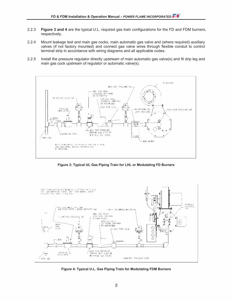
2.2.3 Figure 3 and 4 are the typical U.L. required gas train configurations for the FD and FDM burners, respectively.
2.2.4 Mount leakage test and main gas cocks, main automatic gas valve and (where required) auxiliary valves (if not factory mounted) and connect gas valve wires through flexible conduit to control terminal strip in accordance with wiring diagrams and all applicable codes.
2.2.5 Install the pressure regulator directly upstream of main automatic gas valve(s) and fit drip leg and main gas cock upstream of regulator or automatic valve(s).
Figure 3: Typical UL Gas Piping Train for LHL or Modulating FD Burners
Figure 4: Typical U.L. Gas Piping Train for Modulating FDM Burners
®
5

FD & FDM Installation & Operation Manual - POWER FLAME INCORPORATED
9
2.2.6 Install vent lines from main gas regulator (if used) and (if applicable) diaphragm gas valve. Vent line should be run to the outside of the building, terminating clear of windows or fresh air intakes. Outside terminal of vent should have a screen to prevent insects from building nests in vent pipe. The vent should terminate in a manner, which will preclude the possibility of water, dirt of other matter from entering the line.
2.2.7 Test gas lines for leaks using soap solution. Your local gas service company may wish to carry out or witness this test.
2.2.8 The FDM is equipped with a gas pilot as a standard. The pilot gas train include a solenoid valve and a regulator and it is piped downstream the butterfly valve into the main gas pipe.
2.2.9 CAUTION: Some gas train components may be rated at a maximum of 14” w.c. pressure. When pressure testing the gas train, make certain that the test pressure used does not exceed any components maximum rating.
22..33 WWiirriinngg
2.3.1 Refer to wiring diagram shipped with burner.
2.3.2 Electrical installation must be made in accordance with National Electrical Code and applicable local codes. If this burner is part of a packaged heat exchanger system – check the wiring diagram as supplied by the system manufacturer.
33.. SSTTAARRTT UUPP PPRROOCCEEDDUURREESS
33..11 SSeerrvviiccee TTeesstt EEqquuiippmmeenntt RReeqquuiirreedd
3.1.1 The following test equipment is required to ensure proper start up and adjustment of burner equipment to obtain maximum efficiency and reliability of operation.
3.1.2 See Figure 5 for CO2 versus O2 Curves. These curves correlate the relative values of O2 and CO2 for the fuels listed, as well as the percentage of excess air at given O2 and CO2 values.
3.1.3 Equipment required:
• O2 analyzer (Required) • CO2 indicator (Optional) • NOx indicator • Thermometer (Scale to match process system temperatures) • Draft gauge or inclined manometer • Combination volt/ammeter • DC Micro-ammeter or DC Voltmeter, as required by Flame Safeguard programmer • CO indicator • U-Tube manometers or calibrated pressure gauges 0-16” w.c., 0-35” w.c., and 0-5 PSIG
(Higher pressure ranges may be necessary depending upon gas inlet supply pressure) 3.1.4 In order to fire efficiently, the burner requires an adequate supply of combustion air. Ventilation to
the combustion equipment should be provided in accordance with applicable codes. The combustion equipment area should not become excessively hot and under no circumstances should be under a negative pressure.
®
6

FD & FDM Installation & Operation Manual - POWER FLAME INCORPORATED
10
3.1.5 The burner should be set up initially and serviced at regular intervals by a trained Service person using the proper test instruments. Failure to maintain the correct burner settings may result in inefficient gas consumption, premature wear of burner components, explosion or other safety hazards.
3.1.6 Approximate gas flows and pressures are shown above in Figure 6 and in Table 1 for natural gas and propane.
3.1.4 Note: When firing gas fuels, it is possible to attain CO2 readings that appear to be acceptable (i.e., 8%, 9%, 10%, etc.) while actually producing an unsafe condition. At such CO2 readings, a deficiency of air will create the formation of CO (carbon monoxide) in the flue gases. Therefore, when firing gas or oil, always measure O2 and test for CO to make certain that the burner is adjusted so that it has an excess, rather than a deficiency, of air. CO is a dangerous product of incomplete combustion and is associated with combustion inefficiency and increased fuel cost. CO readings on any fuel should be near 0%.
00 1 2 3 4 5 6 7 8 9 10 11 12 13 14 15 16
1
2
3
4
5
6
7
8
9
10
11
12
13
14
15
16
17
17
#2 Fuel
Propane
Natural
PERCENT EXCESS 02
EXCESS AIRvs. O2
170
160
150
140
120
110
100
90
130
80
70
60
50
30
20
10
40
PER
CEN
T EX
CE
SS
CO
2
PER
CE
NT
EXC
ESS
AIR
Figure 5: CO2 versus O2
®
7
FD & FDM Installation & Operation Manual - POWER FLAME INCORPORATED
10
3.1.5 The burner should be set up initially and serviced at regular intervals by a trained Service person using the proper test instruments. Failure to maintain the correct burner settings may result in inefficient gas consumption, premature wear of burner components, explosion or other safety hazards.
3.1.6 Approximate gas flows and pressures are shown above in Figure 6 and in Table 1 for natural gas and propane.
3.1.4 Note: When firing gas fuels, it is possible to attain CO2 readings that appear to be acceptable (i.e., 8%, 9%, 10%, etc.) while actually producing an unsafe condition. At such CO2 readings, a deficiency of air will create the formation of CO (carbon monoxide) in the flue gases. Therefore, when firing gas or oil, always measure O2 and test for CO to make certain that the burner is adjusted so that it has an excess, rather than a deficiency, of air. CO is a dangerous product of incomplete combustion and is associated with combustion inefficiency and increased fuel cost. CO readings on any fuel should be near 0%.
00 1 2 3 4 5 6 7 8 9 10 11 12 13 14 15 16
1
2
3
4
5
6
7
8
9
10
11
12
13
14
15
16
17
17
#2 Fuel
Propane
Natural
PERCENT EXCESS 02
EXCESS AIRvs. O2
170
160
150
140
120
110
100
90
130
80
70
60
50
30
20
10
40
PER
CEN
T EX
CE
SS
CO
2
PER
CE
NT
EXC
ESS
AIR
Figure 5: CO2 versus O2
7

FD & FDM Installation & Operation Manual - POWER FLAME INCORPORATED
11
33..22 GGeenneerraall SSttaarrtt--UUpp
3.2.1 A thoroughly qualified burner technician must be employed to provide the initial burner start up, as well as any subsequent servicing of the burner and related controls.
3.2.2 Before attempting start up, thoroughly study and familiarize yourself with the exact sequence of operation and all other details on the specific Flame Safeguard Control System being used. If the FSG system is supplied by PFI this information as well as information on other PFI supplied components will be shipped with the burner. All of these should be used as reference material in burner start up and service. (If not supplied by PFI they may be supplied by the package system manufacturer).
3.2.4 Check all system safety devices for proper installation and function.
3.2.5 Lay out combustion testing equipment
3.2.6 Attach gas pressure gauge or manometer of appropriate pressure scale to the manifold pressure tap. Refer to Figure 6 for manifold pressures.
3.2.7 Check the voltage at the disconnect switch to make certain that it matches that shown on the burner label.
3.2.8 Make certain that all heat exchanger dampers are properly positioned for start up.
3.2.9 Install draft gauge to combustion chamber test point.
Manifold Pressure for FDM
0
0.5
1
1.5
2
2.5
3
3.5
4
0 500 1000 1500 2000 2500 3000 3500 4000
Firing Rate (MBH)
Man
ifold
Pre
ssur
e ("
w.c
.)
FDM-250-300-350
FDM-225FDM-150
FDM-75
Figure 6: Manifold Pressures/Firing Rate for Natural Gas
®
8
FD & FDM Installation & Operation Manual - POWER FLAME INCORPORATED
11
33..22 GGeenneerraall SSttaarrtt--UUpp
3.2.1 A thoroughly qualified burner technician must be employed to provide the initial burner start up, as well as any subsequent servicing of the burner and related controls.
3.2.2 Before attempting start up, thoroughly study and familiarize yourself with the exact sequence of operation and all other details on the specific Flame Safeguard Control System being used. If the FSG system is supplied by PFI this information as well as information on other PFI supplied components will be shipped with the burner. All of these should be used as reference material in burner start up and service. (If not supplied by PFI they may be supplied by the package system manufacturer).
3.2.4 Check all system safety devices for proper installation and function.
3.2.5 Lay out combustion testing equipment
3.2.6 Attach gas pressure gauge or manometer of appropriate pressure scale to the manifold pressure tap. Refer to Figure 6 for manifold pressures.
3.2.7 Check the voltage at the disconnect switch to make certain that it matches that shown on the burner label.
3.2.8 Make certain that all heat exchanger dampers are properly positioned for start up.
3.2.9 Install draft gauge to combustion chamber test point.
Manifold Pressure for FDM
0
0.5
1
1.5
2
2.5
3
3.5
4
0 500 1000 1500 2000 2500 3000 3500 4000
Firing Rate (MBH)
Man
ifold
Pre
ssur
e ("
w.c
.)
FDM-250-300-350
FDM-225FDM-150
FDM-75
Figure 6: Manifold Pressures/Firing Rate for Natural Gas

FD & FDM Installation & Operation Manual - POWER FLAME INCORPORATED
12
3.2.10 Connect DC volt meter or microammeter to Flame Safeguard control as appropriate to determine flame detection system signal values. These values can be found in the FSG Control Technical Bulletin.
3.2.11 With the main and leak test cocks in OFF position, turn on gas cock and meter. Check to make certain that pressure upstream of the main gas shutoff cock does not exceed the maximum pressure rating of any of the gas train components. (Refer to Component Spec Sheets).
3.2.12 Check the spark and flame rod electrodes for proper installation and spark gas settings (See Figures 7 and 8). The spark is to arc against the raised tab of the burner diffuser. If a UV scanner is used, make certain it is securely in place.
3.2.13 With the manual gas cocks closed, turn the burner switch ON. The burner blower will operate and the air damper will be driven to the open position to begin its pre-purge cycle, once the high fire purge switch is made. This switch is located on the damper actuator. Refer to the wiring diagram shipped with the burner and adjust the switch to close near the high fire position.
Figure 7: FD/FDM Burner Flame Rod
Figure 8: FD/FDM Burner Electrode
®
9

FD & FDM Installation & Operation Manual - POWER FLAME INCORPORATED
13
3.2.14 The pre-purge cycle may be as short as 30 seconds. At the end of the pre-purge cycle the damper will be driven to the low fire position. Once in the low fire position, the low fire switch located on the actuator should close. If the low fire switch is not closed, refer to the wiring diagram shipped with the burner and adjust the switch to close near low fire position (closed damper). The ignition transformer and automatic gas valves will energize. With the manual gas cocks closed, the burner should go into a safety lockout condition. The flame safeguard will have to be reset manually.
3.2.15 The FDM comes with a gas pilot. To set the proper gas pressure for the pilot, run a cycle as described above, with the manual gas valve closed, and once the ignition transformer is energized set your gas pilot pressure until there is a stable signal on your flame safeguard.
3.2.16 Burner Light Off Procedure
• Prior to start up make certain that the gas butterfly valve (BFV) linkage and air damper are set to operate in all positions without binding. Refer to Figure 9 (Linkage arrangement). Note: depress declutching mechanism to manually move the damper and BFV
• Start the burner. The actuator will drive to the high fire (open damper) position where the high fire switch will close and begin the pre-purge.
Approximate Linkage arrangement.Shown in the low fire position;damper is closed and gas valvenearly closed. The approximate 90degree angle between the damperarm and gas valve must be set atlow fire.
Low Fire Switch (set to close nearlow fire)High Fire Switch (set to close nearhigh fire)NOTE: Set the low and high firestops located under switch asm.
Direction Control (By selection, azero input can drive damper eitherclockwise or counter clockwise.(arrow at CCW = damper drivesclosed with Zero control inputsignal.
Manifold pressure tap for FD
Slide Damper (May be used torestrict air flow at high fire to allowrotating damper full movement).Used when the high fire rate is lessthan burner's maximum.
Declutching Mechanism. Push tomanually operate actuator.
Manifold/Pilot pressure tap for FDMwith pilot.
FDM pilot gas train.
Figure 9: Linkage Setup for FDM Burner
®
10
FD & FDM Installation & Operation Manual - POWER FLAME INCORPORATED
13
3.2.14 The pre-purge cycle may be as short as 30 seconds. At the end of the pre-purge cycle the damper will be driven to the low fire position. Once in the low fire position, the low fire switch located on the actuator should close. If the low fire switch is not closed, refer to the wiring diagram shipped with the burner and adjust the switch to close near low fire position (closed damper). The ignition transformer and automatic gas valves will energize. With the manual gas cocks closed, the burner should go into a safety lockout condition. The flame safeguard will have to be reset manually.
3.2.15 The FDM comes with a gas pilot. To set the proper gas pressure for the pilot, run a cycle as described above, with the manual gas valve closed, and once the ignition transformer is energized set your gas pilot pressure until there is a stable signal on your flame safeguard.
3.2.16 Burner Light Off Procedure
• Prior to start up make certain that the gas butterfly valve (BFV) linkage and air damper are set to operate in all positions without binding. Refer to Figure 9 (Linkage arrangement). Note: depress declutching mechanism to manually move the damper and BFV
• Start the burner. The actuator will drive to the high fire (open damper) position where the high fire switch will close and begin the pre-purge.
Approximate Linkage arrangement.Shown in the low fire position;damper is closed and gas valvenearly closed. The approximate 90degree angle between the damperarm and gas valve must be set atlow fire.
Low Fire Switch (set to close nearlow fire)High Fire Switch (set to close nearhigh fire)NOTE: Set the low and high firestops located under switch asm.
Direction Control (By selection, azero input can drive damper eitherclockwise or counter clockwise.(arrow at CCW = damper drivesclosed with Zero control inputsignal.
Manifold pressure tap for FD
Slide Damper (May be used torestrict air flow at high fire to allowrotating damper full movement).Used when the high fire rate is lessthan burner's maximum.
Declutching Mechanism. Push tomanually operate actuator.
Manifold/Pilot pressure tap for FDMwith pilot.
FDM pilot gas train.
Figure 9: Linkage Setup for FDM Burner
10

FD & FDM Installation & Operation Manual - POWER FLAME INCORPORATED
14
• After the pre-purge sequence the actuator will drive to the low fire position where the low fire end switch will close, indicating the low fire position. For the FD burner the ignition transformer and main gas valves will energize at the same time (direct spark system). For the FDM burner the gas pilot will establish before the main gas valves will be energized. The trial for ignition will be only four seconds. Flame should be established immediately.
• Either the high or low fire end switches do not close during the light off sequence (refer to Figure 9 and wiring diagram supplied with the burner to set the switches).
• At initial start up, air may be trapped in the gas lines so more than one attempt to light off may be required.
• Once flame is established, run the mod motor to position the gas butterfly valve wide open. Adjust the gas pressure regulator to provide the recommended pressures at the burner manifold pressure tap (Figure 4). If there is any question as to the actual firing rate – the job site gas meter should be clocked.
• Adjust the gas butterfly valve to provide smooth light off and stable combustion throughout the firing range. To achieve the burners’ maximum turndown the butterfly valve will be nearly fully closed in the low fire position.
• Once the high fire rate has been set, if it is necessary to reduce the excess of O2 to an acceptable level, setting the sliding damper (see Figure 9).
• For indirect fired applications, use a combustion analyzer to make certain that the burner settings provides the correct CO2 or O2 levels. Generally accepted values for natural gas are 8 ½ to 10% or 5 ½ to 3% O2. Equivalent readings on propane gas are 10 to 11 ½% CO2 or 5 ½ to 3 ½% O2. It is important that the CO level is checked and held at minimum for both direct and indirect fired applications.
• Once the burner is in operation, set all gas pressure switches and other burner and heat exchanger system control devices for correct operation. Follow all test procedures as recommended by the flame safeguard and other control and device manufacturers.
• Record all data (Section 6) for future reference.
NOTE : Although Underwriters Laboratories permits higher readings of CO (carbon monoxide) for indirect fired applications, it is desirable to obtain readings between 0 and 100PPM, depending on local codes and heat exchanger manufacturer’s recommendations.
11

FD & FDM Installation & Operation Manual - POWER FLAME INCORPORATED
15
44.. PPAARRTTSS LLIISSTT
44..11 FFDD PPaarrttss LLiisstt 1 INLET SCREEN ASSEMBLY P/N D20031 FD75 P/N D20030 FD150, FD225, & FD300 P/N D20032 FD350 2 INLET RING P/N X08654 FD75 P/N X08655 FD150, FD225, & FD300 P/N X08681 FD300 3 AIR HOUSING P/N D20044 FD75 P/N D20043 FD150 P/N D20040 FD225 P/N D20300 FD300 P/N D20302 FD350 4 BLOWER WHEEL P/N 080010 FD75 P/N 080020 FD150 P/N 080000 FD225 P/N 080040 FD300 P/N 081100 FD350 5 MOTOR PLATE P/N D10414 FD75 P/N D10404 FD150 & FD225 P/N D10325 FD300 P/N C10730 FD350 6 BLOWER MOTOR
P/N 050000 FD75 P/N 054120 FD150 P/N 054160 FD225 P/N 054180 FD300 P/N 050370 FD350 7 SLIDING DAMPER P/N D10235 FD75 P/N D10236 FD150 P/N D10229 FD225 P/N D10350 FD300 & FD350 8 EXTENDED COMBUSTION SHIELD P/N D20050 FD75 P/N D20060 FD150 P/N D20070 FD225 P/N D20090 FD300 & FD350
®
12
FD & FDM Installation & Operation Manual - POWER FLAME INCORPORATED
16
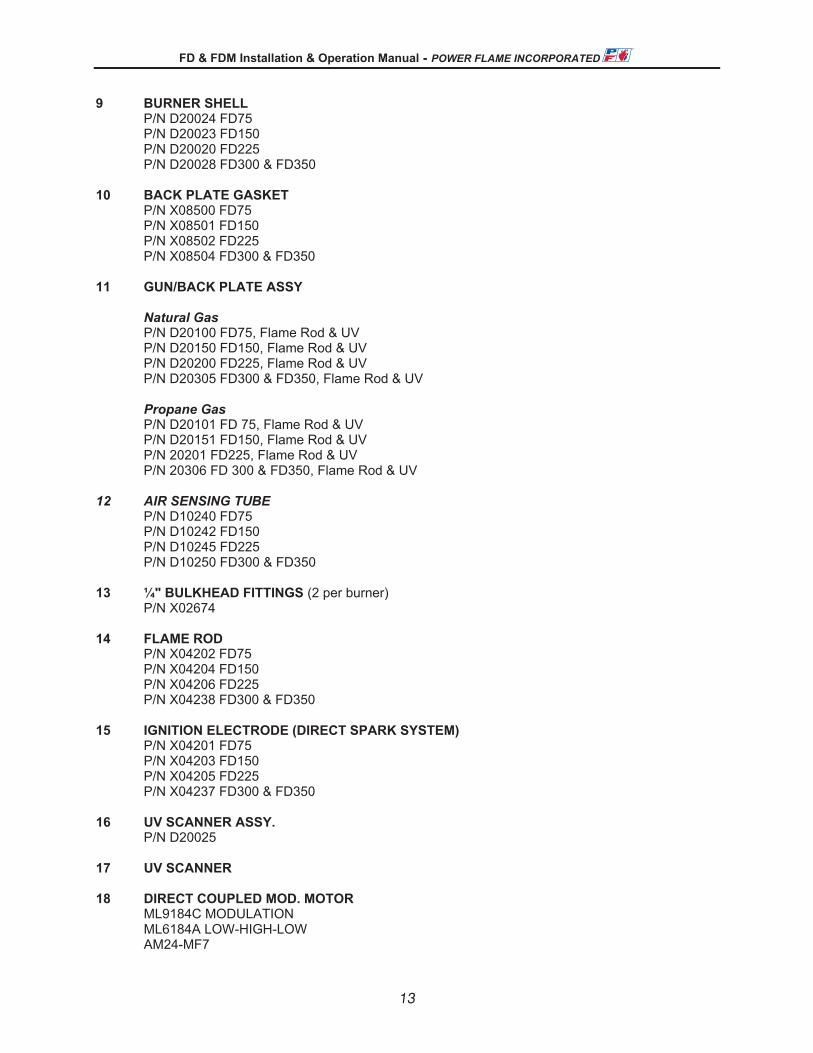
9 BURNER SHELL P/N D20024 FD75 P/N D20023 FD150 P/N D20020 FD225 P/N D20028 FD300 & FD350 10 BACK PLATE GASKET P/N X08500 FD75 P/N X08501 FD150 P/N X08502 FD225 P/N X08504 FD300 & FD350 11 GUN/BACK PLATE ASSY
Natural Gas P/N D20100 FD75, Flame Rod & UV P/N D20150 FD150, Flame Rod & UV P/N D20200 FD225, Flame Rod & UV P/N D20305 FD300 & FD350, Flame Rod & UV Propane Gas
P/N D20101 FD 75, Flame Rod & UV P/N D20151 FD150, Flame Rod & UV
P/N 20201 FD225, Flame Rod & UV P/N 20306 FD 300 & FD350, Flame Rod & UV 12 AIR SENSING TUBE P/N D10240 FD75 P/N D10242 FD150 P/N D10245 FD225 P/N D10250 FD300 & FD350 13 ¼" BULKHEAD FITTINGS (2 per burner) P/N X02674 14 FLAME ROD P/N X04202 FD75 P/N X04204 FD150 P/N X04206 FD225 P/N X04238 FD300 & FD350 15 IGNITION ELECTRODE (DIRECT SPARK SYSTEM) P/N X04201 FD75 P/N X04203 FD150 P/N X04205 FD225 P/N X04237 FD300 & FD350 16 UV SCANNER ASSY. P/N D20025 17 UV SCANNER 18 DIRECT COUPLED MOD. MOTOR ML9184C MODULATION ML6184A LOW-HIGH-LOW AM24-MF7
®
13

FD & FDM Installation & Operation Manual - POWER FLAME INCORPORATED
17
AMCX24-MF7 MODULATION SIEMENS SQH71 MODULATION 19 DAMPER SHAFT P/N X09103 20 MOD. MOTOR BRACKET P/N M15105 1" BFV P/N M15100 1 ¼” BFV P/N M15104 1 ½” BFV P/N M15106 2" BFV 21 BUTTERFLY VALVE
P/N 273100, 1” FD75 P/N 273200, 1 ¼” FD150 P/N 273300, 1 ½” FD225 P/N 273400, 2” FD300 P/N 273400, 2” FD350
22 SIDE ORIFICE SPRING PRE-DRILLED (as required) 23 SIDE ORIFICE PRE-DRILLED (as required) 24 SIDE ORIFICE TEE AND PLUG (as required) 25 HIGH GAS PRESSURE SWITCH 26 BALL VALVES 27 MAIN GAS VALVE Solenoid, Diaphragm, Motorized 28 LOW GAS PRESSURE SWITCH 29 AUXILLARY GAS VALVE
Solenoid, Diaphragm, Motorized 30 GAS PRESSURE REGULATOR 31 PANEL BOX CHASSIS 15.5" x 10" 32 TERMINAL BLOCKS & DIN RAIL 33 BURNER FSG CONTROL SUBBASE 34 BURNER FSG CONTROL RM7800 SERIES 35 GROUNDING LUG 36 LOW FIRE START RELAY (if required) 37 MOTOR GL7 RELAY (as required)
MOTOR CONTACTOR MOTOR STARTER
38 PANEL BOX DOOR 15.5" x 10"
®
14
FD & FDM Installation & Operation Manual - POWER FLAME INCORPORATED
18
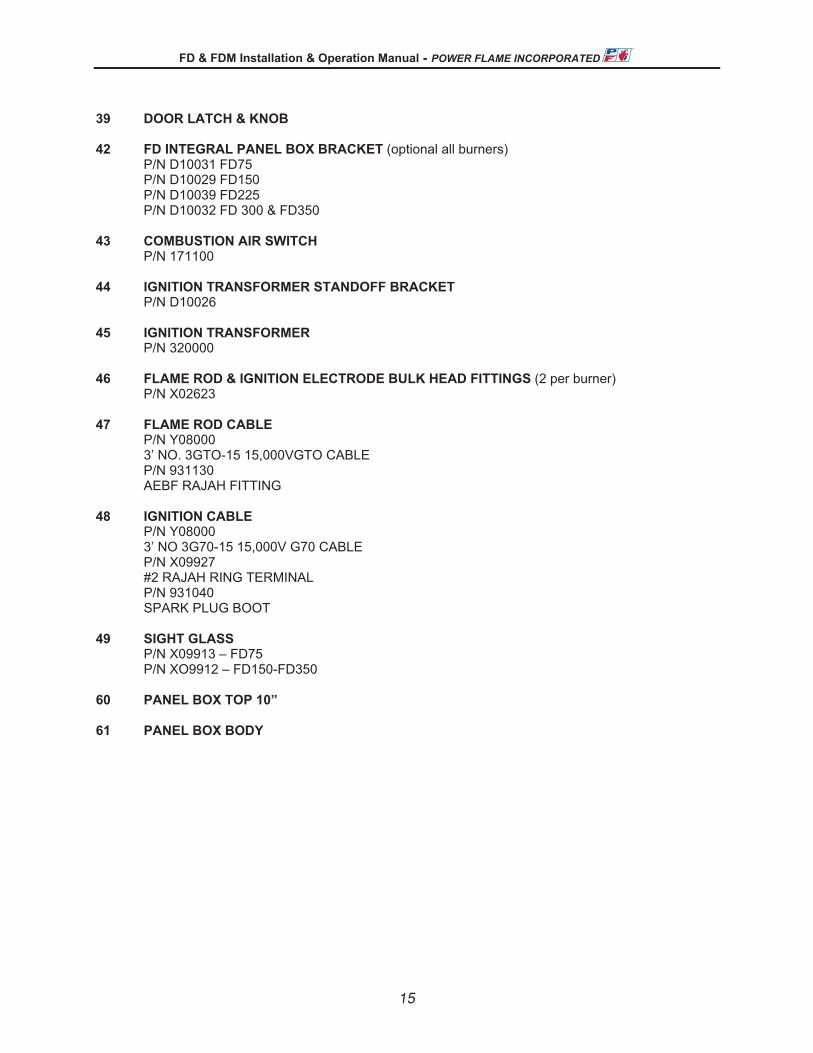
39 DOOR LATCH & KNOB 42 FD INTEGRAL PANEL BOX BRACKET (optional all burners)
P/N D10031 FD75 P/N D10029 FD150 P/N D10039 FD225
P/N D10032 FD 300 & FD350 43 COMBUSTION AIR SWITCH
P/N 171100 44 IGNITION TRANSFORMER STANDOFF BRACKET P/N D10026 45 IGNITION TRANSFORMER
P/N 320000 46 FLAME ROD & IGNITION ELECTRODE BULK HEAD FITTINGS (2 per burner) P/N X02623 47 FLAME ROD CABLE P/N Y08000 3’ NO. 3GTO-15 15,000VGTO CABLE P/N 931130 AEBF RAJAH FITTING 48 IGNITION CABLE P/N Y08000 3’ NO 3G70-15 15,000V G70 CABLE P/N X09927 #2 RAJAH RING TERMINAL P/N 931040 SPARK PLUG BOOT 49 SIGHT GLASS
P/N X09913 – FD75 P/N XO9912 – FD150-FD350
60 PANEL BOX TOP 10” 61 PANEL BOX BODY
®
15
FD & FDM Installation & Operation Manual - POWER FLAME INCORPORATED
19
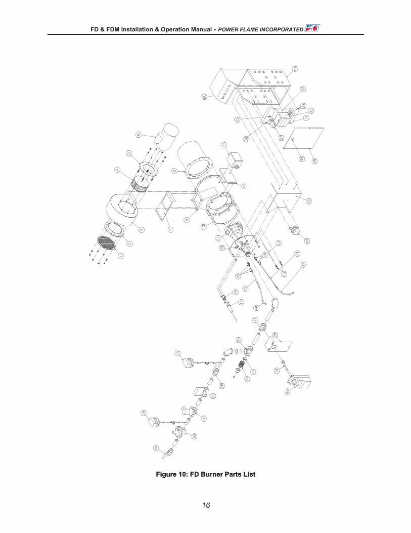
Figure 10: FD Burner Parts List
®
16
FD & FDM Installation & Operation Manual - POWER FLAME INCORPORATED
19
Figure 10: FD Burner Parts List
®
16

FD & FDM Installation & Operation Manual - POWER FLAME INCORPORATED
20
44..22 FFDDMM PPaarrttss LLiisstt 2 INLET RING P/N X08654 with P/N A11795 FDM75 P/N A11774 FDM150 P/N X08653 FDM225 P/N X08681 FDM 300 & FDM 350 3 AIR HOUSING P/N D20046 FDM75 P/N D20047 FDM150 P/N D20039 FDM225 P/N D20302 FDM 300 & FDM 350 4 BLOWER WHEEL P/N 080010 FDM 75 P/N 084900 FDM 150 P/N 085300 FDM 225 P/N 081050 FDM 300 P/N 081100 FDM 350 5 MOTOR PLATE P/N D10414 FDM75 P/N D10404 FDM150 P/N D10324 FDM225 P/N C10730 FDM 300 & FDM 350 6 BLOWER MOTOR P/N 050000 FDM 75 P/N 054120 FDM 150 P/N 054160 FDM 225 P/N 054210 FDM 300 P/N 050370 FDM 350 7 SLIDING DAMPER P/N D10235 FD75 P/N D10236 FD150 P/N D10229 FD225 P/N D10350 FD300 & FD350 8 EXTENDED COMBUSTION SHIELD (required for direct fired applications) P/N D20050 FD75 P/N D20060 FD150 P/N D20070 FD225 P/N D20090 FD300 & FD350 9 BURNER SHELL - STANDARD 2” BURNER P/N D20024 FD75 P/N D20023 FD150 P/N D20020 FD225
P/N D20028 FD300&FD350 10 BACK PLATE GASKET P/N X08500 FD75 P/N X08501 FD150
®
17

FD & FDM Installation & Operation Manual - POWER FLAME INCORPORATED
21
P/N X08502 FD225 P/N X08504 FD300 & FD350 11 GUN/BACK PLATE ASSEMBLY STANDARD 2” BURNER
Natural Gas P/N D20100 FD75, Flame Rod & UV P/N D20150 FD150, Flame Rod & UV P/N D20200 FD225, Flame Rod & UV P/N D20305 FD300 & FD350, Flame Rod & UV Propane Gas P/N D20101 FD 75, Flame Rod & UV P/N D20151 FD150, Flame Rod & UV P/N 20201 FD225, Flame Rod & UV P/N 20306 FD 300 & FD350, Flame Rod & UV 14 FLAME ROD P/N X04202 FD75 P/N X04204 FD150 P/N X04206 FD225 P/N X04238 FD300 & FD350 15 IGNITION ELECTRODE P/N X04201 FD75 P/N X04203 FD150 P/N X04205 FD225 P/N X04237 FD300 & FD350 16 UV SCANNER ASSY. P/N D20025 17 UV SCANNER 18 AM24-MFT DIRECT COUPLED MOD MOTOR
P/N 060932 P/N D10023 (with mounting bracket) AMCX24-MFT
P/N 060929 19 PIE DAMPER AXLE P/N X01470 21 BUTTERFLY VALVE
P/N 273100, 1” FDM75 P/N 273200, 1 ¼” FDM 150 P/N 273300, 1 ½” FDM225 P/N 273400, 2” FDM300 & FDM350
22 SIDE ORIFICE SPRING Pre-Drilled (As Required) 23 SIDE ORIFICE Pre-Drilled (As Required) 24 SIDE ORIFICE TEE AND PLUG (As Required) 25 HIGH GAS PRESSURE SWITCH
®
18

FD & FDM Installation & Operation Manual - POWER FLAME INCORPORATED
22
26 BALL VALVES 27 MAIN GAS VALVE Solenoid, Diaphragm, Motorized 28 LOW GAS PRESSURE SWITCH 29 AUXIALLIARY GAS VALVE
Solenoid, Diaphragm, Motorized 30 GAS PRESSURE REGULATOR 31 PANEL BOX CHASSIS 15.5" x 10" 32 TERMINAL BLOCKS & DIN RAIL 33 BURNER FSG CONTROL SUBBASE 34 BURNER FSG CONTROL RM7800 SERIES 35 GROUNDING LUG 36 LOW FIRE START RELAY (If Required) 37 MOTOR GL7 RELAY (As Required)
Motor Contactor and Motor Starter 38 PANEL BOX DOOR 15.5" x 10" 39 DOOR LATCH & KNOB 42 FD INTEGRAL PANEL BOX BRACKET
P/N D10031 FD75 P/N D10029 FD150 P/N D10039 FD225
P/N D10032 FD 300 & FD350 (Use ILO #59 for Burner Mounted Panel)
43 COMBUSTION AIR SWITCH
P/N 171100 44 IGNITION TRANSFORMER STANDOFF BRACKET P/N D10026 45 IGNITION TRANSFORMER
P/N 320000 46 FLAME ROD & IGNITION ELECTRODE BULK HEAD FITTINGS (2 per Burner)
P/N X02623 47 FLAME ROD CABLE P/N Y08000 3’ NO. 3GTO-15 15,000VGTO CABLE P/N 931130 AEBF RAJAH FITTING 48 IGNITION CABLE P/N Y08000 3’ NO 3G70-15 15,000V G70 CABLE
®
19

FD & FDM Installation & Operation Manual - POWER FLAME INCORPORATED
23
P/N X09927 #2 RAJAH RING Terminal P/N 931040 Spark Plug Boot 49 SIGHT GLASS
P/N X09913 – FD75 P/N XO9912 – FD150-FD350
50 BUTTERFLY VALVE DAMPER ARM P/N M80035 50 AM24 DAMPER ARM
P/N P82120 51 DAMPER CONTROL SWIVEL (2 Required per Burner)
P/N 911000 52 5/16” LINKAGE ROD
P/N Y00470 53 PIE DAMPER OUTER PLATE
P/N L10207 FDM75-FDM250 P/N D10353 FDM300 & FDM 350 53 PIE DAMPER MID PLATES
P/N L10206 FDM75-FDM250 P/N D10352 FDM300 & FDM350
53 PIE DAMPER INNER PLATES
P/N L10205 FDM75-FDM250 P/N D10351 FDM300 & FDM350
54 PIE DAMPER RETAINING BUSHINGS (4 required per burner)
P/N X01473 55 PIE DAMPER AXEL BUSHING
P/N X02390 56 PIE DAMPER BAND
P/N D10398 FDM75-FDM250 (FDM300 & FDM 350 not required) 57 TERMINAL BLOCKS & DIN RAIL 58 8 X 6 HOFFMAN J-BOX
P/N X09950 59 COMUSTION AIR SWITCH & 8 X J-BOX STANDARD BRACKET
P/N D10028 60 PANEL BOX TOP 10” 61 PANEL BOX BODY 15.5” x 10” 62 SOLENOID VALVE (GAS PILOT) 63 REGULATOR (GAS PILOT)
20
®

FD & FDM Installation & Operation Manual - POWER FLAME INCORPORATED
24
Figure 11: FDM Burner Parts List
®
21
FD & FDM Installation & Operation Manual - POWER FLAME INCORPORATED
24
Figure 11: FDM Burner Parts List
®
21

FD & FDM Installation & Operation Manual - POWER FLAME INCORPORATED
25
55.. MMAAIINNTTEENNAANNCCEE
55..11 GGeenneerraall IInnffoorrmmaattiioonn
5.1.1 Only qualified service technicians should make mechanical or electrical adjustments to the burner and/or associated control equipment.
5.1.2 Preventive maintenance can usually be performed by building maintenance personnel.
5.1.3 Always follow the information provided in the Owner Operating Instructions on Page 27. These should be conspicuously posted in the burner room at the time of the initial burner installation and startup.
5.1.4 Always turn the power supply off to the burner and close manual fuel valves as appropriate for routine maintenance.
5.1.5 Make sure that combustion and ventilation fresh air sources to the burner room remain clean and open.
5.1.6 Periodically check all electrical connections and make sure the flame safeguard control chassis is firmly connected to its wiring base.
5.1.7 Refer to manufacturer’s product bulletins supplied with the burner for maintenance on the flame safeguard control and other components.
5.1.8 Refer to heat exchanger manufacturer’s instructions for general inspection procedures and for specific testing and inspection of all liquid level controls, pressure/temperature relief and other applicable items.
5.1.9 If you have any questions about the procedures listed above or questions relating to components or devices on your unit not specifically covered in the above, contact our Service Department at (620) 421-0480 for assistance.
®
22
FD & FDM Installation & Operation Manual - POWER FLAME INCORPORATED
26
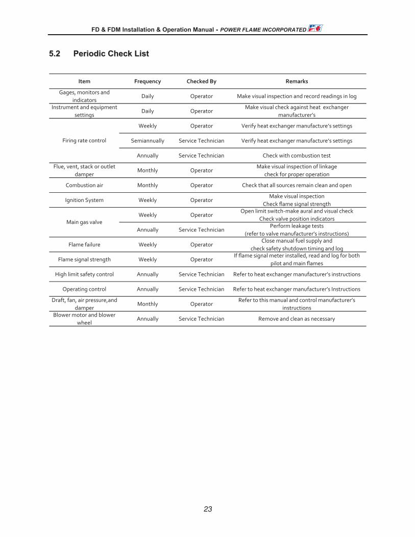
55..22 PPeerriiooddiicc CChheecckk LLiisstt
skrameRyB dekcehCycneuqerFmetI
Gages, monitors and indicators
Daily Operator Make visual inspection and record readings in log
Instrument and equipment settings
Daily OperatorMake visual check against heat exchanger
manufacturer’s
Weekly Operator Verify heat exchanger manufacture’s settings
Semiannually Service Technician Verify heat exchanger manufacture’s settings
Annually Service Technician Check with combustion test
Flue, vent, stack or outlet damper
Monthly OperatorMake visual inspection of linkage
check for proper operation
Combustion air Monthly Operator Check that all sources remain clean and open
Ignition System Weekly OperatorMake visual inspection
Check flame signal strength
Weekly OperatorOpen limit switch-make aural and visual check
Check valve position indicators
Annually Service TechnicianPerform leakage tests
(refer to valve manufacturer’s instructions)
Flame failure Weekly OperatorClose manual fuel supply and
check safety shutdown timing and log
Flame signal strength Weekly OperatorIf flame signal meter installed, read and log for both
pilot and main flames
High limit safety control Annually Service Technician Refer to heat exchanger manufacturer’s instructions
Operating control Annually Service Technician Refer to heat exchanger manufacturer’s Instructions
Draft, fan, air pressure,and damper
Monthly OperatorRefer to this manual and control manufacturer’s
instructionsBlower motor and blower
wheelAnnually Service Technician Remove and clean as necessary
Firing rate control
Main gas valve
66.. BBUURRNNEERR SSTTAARRTT UUPP IINNFFOORRMMAATTIIOONN && TTEESSTT DDAATTAA
The following information shall be recorded for each burner start up
Power Flame model No.____________________ Invoice No.___________________ Serial No._________________
Installation Name________________________________________________________________________________
Start Up Contractors Name________________________________________________________________________
Phone_______________________________________ Start Up Date_______________________________________
Name of Technician Performing Start Up_____________________________________________________________
Type of Gas: Natural Gas_____ LP_____ Other _______________________________________
®
23

FD & FDM Installation & Operation Manual - POWER FLAME INCORPORATED
27
eriF woLFFO renruB
eriF hgiHeriF woL
eriF woLeriF hgiH
eriF hgiHeriF woL
eriF woLeriF hgiH
eriF hgiHeriF woL
eriF woLeriF hgiH
eriF hgiHeriF woL
eriF woLeriF hgiH
eriF hgiHeriF woL
stloVeriF hgiH
esahPeriF woL
zHeriF hgiH
stloVtiucriC lortnoCeriF hgiHspmA rotoM rewolB
Stack OutletTest Point Draft
CO (ppm)
Gas Pressure atManifold
Gas Firing
Net Stack Temperature
OverFire Draft
Flame Signal
O2 (%)
NOx (ppm)
CombustionEfficiency (%)
Input Rate (MBH)
Power Supply
Gas Pressure at Train Inlet
Operating control cut out setting
Operating control cut in setting
Limit control cut out setting
Limit control cut in setting
Low gas pressure switch (")
High gas pressure switch (")Gas
Control Settings
General
®
2422
NOVA PLUS Installation & Operation Manual - POWER FLAME INCORPORATED ENTERESC
®
6. BURNER START UP INFORMATION & TEST DATA
The following information shall be recorded for each burner start up:
Power Flame Model No. _____________ Invoice No.__________________ Serial No.__________________________________
Installation Name_________________________________ Start Up Date____________________________________________
Start Up Contractors Name___________________________________ Phone________________________________________
Name of Technician Performing Start Up______________________________________________________________________
Type of Gas Natural LP Other __________________________
Gas FiringGas Pressure at Train Inlet Flame signal Readings Stack Outlet Test Point DraftBurner in Off Position ________” W.C. Pilot________________________ Low Fire ____________________
Low Fire ____________________ High Fire____________________Gas Pressure at Train Inlet High Fire____________________Low Fire_______________________ Net Stack TemperatureHigh Fire ______________________ O2 Low Fire ____________________
Low Fire ____________________ High Fire____________________Gas Pressure at Firing Head High Fire____________________Low Fire_______________________ Combustion EfficiencyHigh Fire ______________________ CO Low Fire ___________________%
Low Fire ____________________ High Fire___________________%Gas Pressure at Pilot Test Tee High Fire__________________________________________________ NOx Measured
Input Rate BTU/HR Low Fire ____________________Power Supply Low Fire ____________________ High Fire____________________Volts_____ Ph_______ Hz ________ High Fire____________________Control Circuit Volts______________Blower Motor amps at high fire _____ Over Fire Draft______________________________ Low Fire ____________________
High Fire____________________
Control SettingsGeneral GasOperating control cut out setting_______ Low gas pressure switch_________in.Operating control cut in setting________ High gas pressure switch_________inLimit control cut out setting___________Limit control cut in setting____________
Operation ChecklistChecked for Proper Operation of: Yes No Yes NoLow water cut off ( ) ( ) Barometric damper ( ) ( )High water cut off ( ) ( ) Boiler room combustion air and ventilation ( ) ( )Flame safeguard control ignition failure ( ) ( ) provisions correctFlame safeguard control main flame failure ( ) ( )Burner air flow switch ( ) ( )Induced draft fan controls ( ) ( ) All gas lines checked for leaks ( ) ( )Over fire draft controls ( ) ( ) Gas lines and controls properly vented ( ) ( )Fresh air damper end switch ( ) ( ) Other system components (specify) ( ) ( )Notified_________________________________of the following system deficiencies:_______________________________________
___________________________________________________________________________________________________________
___________________________________________________________________________________________________________
___________________________________________________________________________________________________________

FD & FDM Installation & Operation Manual - POWER FLAME INCORPORATED
5
11..33 CCAAPPAACCIITTIIEESS && SSPPEECCIIFFIICCAATTIIOONNSS
Model Number ** FD/FDM75 FD/FDM150 FD/FDM225 FD/FDM250 FD/FDM300 FD/FDM350
Max Rate (MBH) 750 1500 2250 2500 3000 3500
Min Rate (MBH)Type FD 30 50 75 80 90 105
Min Rate (MBH)Type FDM 38 75 113 125 150 175
Blower Wheel SizeType FD 5 1 /16 x 1 1 /2 5 3 /4 x 1 1 /2 5 3 /4 x 2 1 /2 5 3 /4 x 3 5 3 /4 x 3 1 /2 5 3 /4 x 3 1 /2
Blower Wheel SizeType FDM 5 1 /16 x 1 1 /2 6 1 /4 x 3 7 x 3 7 x 3 7 5 /8 x 3 7 5 /8 x 3 1 /2
Blower Motor (HP) 1 /4 1 /3
1 /2 3 /4 1 1 1 /2
Manifold Pressure *Natural Gas (" wc) 2.8 1.9 2.1 2.3 2.9 4.0
Manifold Pressure *Propane (" wc) 5.6 4.3 4.1 4.1 3.8 7.5
Turndown Ratio (FD/FDM) 30/20 30/20 30/20 30/20 30/20 30/20
Table 1: specification FD and FDM burners
* To achieve maximum rating against 0.0” w.c. chamber pressure
** Model FDMR also includes data in table and the “R” indicates that the burner is mounted in the inverted position i.e. the fan housing is located above the burner blast tube centerline versus below the blast tube centerline.
11..44 WWaarrrraannttyy aanndd SSppaarree PPaarrttss IInnffoorrmmaattiioonn
1.4.1 Power Flame offers a 15 month Limited Warranty on all components from the date of shipment (see inside of back cover for details).
1.4.2 The Owners Information envelope packed with the burner contains a Warranty Registration Card. The Warranty Registration Card is also a request form for a computer generated Spare Parts List. An on-hand supply of spare parts is highly recommended in case of emergency shutdown. The pre-addressed, postage paid Warranty Registration Card should be completed and returned to Power Flame. In the event that the Warranty Registration Card is lost, please contact Power Flame’s Customer Service Department in Parsons, Kansas or you may register on-line through the Power Flame website (www.powerflame.com). All communications with the factory will be handled more efficiently if the burner is identified by the burner model, serial and job numbers. This information is stamped into the burner nameplate that is attached to the integral control panel (or to the burner, when remote control panels are supplied).
®
2527
NOVA PLUS Installation & Operation Manual - POWER FLAME INCORPORATED
DC4 DRAFT CONTROL
ENTERESC
®
NOTES: ___________________________________________________________________
__________________________________________________________________________
__________________________________________________________________________
__________________________________________________________________________
__________________________________________________________________________
__________________________________________________________________________
__________________________________________________________________________
__________________________________________________________________________
__________________________________________________________________________
__________________________________________________________________________
__________________________________________________________________________
__________________________________________________________________________
__________________________________________________________________________
__________________________________________________________________________
__________________________________________________________________________
__________________________________________________________________________
__________________________________________________________________________
__________________________________________________________________________
__________________________________________________________________________
__________________________________________________________________________
__________________________________________________________________________
__________________________________________________________________________
__________________________________________________________________________
__________________________________________________________________________
__________________________________________________________________________

26
NOVA PLUS Installation & Operation Manual - POWER FLAME INCORPORATED
DC4 DRAFT CONTROL
ENTERESC
®
7. OWNER OPERATING INSTRUCTIONSFOR YOUR SAFETYIf you smell gas:1. Open windows2. Do not touch electrical switches
3. Extinguish any open flame4. Call your gas supplier immediately
Do not store or use gasoline or other flammable liquids and vapors in the vicinity of this or anyother appliance.
IMPORTANT PRECAUTIONS1. Never attempt to light burner with paper or other materials.2. Never experiment with the burner.3. Never change the fuel or air adjustments without consulting with the burner service company.
4. Never attempt to light the burner if combustion chamber contains any unburned fuel or gases.5. Never throw waste paper, rags, garbage or other waste materials into the combustion chamber. 6. Never wash out heating equipment room without first covering the burner with waterproof material.
WARNINGImproper installation, adjustment, alteration, service or maintenance can cause injury or propertydamage. Refer to the burner manual. For assistance or additional information consult a qualifiedinstaller, service agency or the gas supplier.
Preparation for Start Up - All Fuels 1. Ensure that the system is in working order. If heat exchanger is a boiler, ensure that proper water level is available.
2. Set the burner control panel switch to the OFF position.
3. Combination Gas Burner – set the fuel selector switch to the fuel to be burned.
Start Up1. Manually open and close the main gas shut off cock, leak test cock and pilot cock to determine that they operate freely. Open all three cocks. (Reset low gas pressure switch if supplied).
2. Set the main power switch and burner panel control switch to the ON position. Wait 30 seconds and turn up thermostat or operating control to the desired setting.
3. The burner blower motor will start and after a suitable pre-purge period (this will vary with the type of flame safeguard control supplied – but will usually be a minimum of 30 seconds), the burner pilot will light, after which the main flame will be established.
4. If the system does not respond properly, contact your qualified burner service company.
EXTENDED SHUT DOWN1. Place main power switch and burner control panel switch in the OFF position.2. Close all gas valves.3. Cover burner to protect it from dust and dampness.
MAINTENANCE1. See Maintenance section in burner manual for suggestions on periodic maintenance and
Burner Service Company Date of Installation
Address Telephone
service.
4. Turn the thermostat or operating control down to its lowest setting.
5. Check fuses and replace as necessary.
6. Depress the flame safeguard programming control reset button.
Rem
ove
this
pag
e an
d po
st n
ear b
urne
r.
26
FD & FDM Installation & Operation Manual - POWER FLAME INCORPORATED
28
yes no
Other systems conponents (Spcify)
Checked for proper operation of:
OPERATION CHECKLIST
Burner Air Flow Switch
Gas lines and controls properlt vented
Combustion and ventilation provisions
all gas lines checked for leaks
Flame Safeguard control ignition failure
Flame Safeguard control main flame failure
Notified____________________________________________________________of the following system
deficiencies:____________________________________________________________________________
_______________________________________________________________________________________
_______________________________________________________________________________________
_______________________________________________________________________________________
_______________________________________________________________________________________
Notes:_________________________________________________________________________________
_______________________________________________________________________________________
_______________________________________________________________________________________
_______________________________________________________________________________________
_______________________________________________________________________________________
_______________________________________________________________________________________
_______________________________________________________________________________________
_______________________________________________________________________________________
_______________________________________________________________________________________
_______________________________________________________________________________________
_______________________________________________________________________________________
®

FD & FDM Installation & Operation Manual - POWER FLAME INCORPORATED
1. GENERAL PRODUCT INFORMATION ............................................................................................... 1.1 PRINCIPLE OF OPERATION................................................................................................................... 1.2 MODEL IDENTIFICATION.................................................................................................................... 1.3 CAPACITIES & SPECIFICATIONS ......................................................................................................... 1.4 WARRANTY AND SPARE PARTS INFORMATION ....................................................................................
2. INSTALLATION ................................................................................................................................... 2.1 BURNER MOUNTING: GENERAL ........................................................................................................ 2.2 GAS PIPING .............................................................................................................................. 2.3 WIRING ...............................................................................................................................
3. START UP PROCEDURES ................................................................................................................. 3.1 SERVICE TEST EQUIPMENT REQUIRED................................................................................................ 3.2 GENERAL START-UP.......................................................................................................................
4. PARTS LIST..................................................................................................................... .................. 4.1 FD PARTS LIST............................................................................................................................... 4.2 FDM PARTS LIST .........................................................................................................................
5. MAINTENANCE................................................................................................................................. 5.1 GENERAL INFORMATION ............................................................................................................... 5.2 PERIODIC CHECK LIST......................................................................................................................
6. BURNER START UP INFORMATION & TEST DATA.......................................................................
7. OWNER OPERATING INSTRUCTIONS.............................................................................................
®
11122
3346
668
12
1217
222223
24
26
PPoowweerr FFllaammee IInnccoorrppoorraatteedd LLiimmiitteedd WWaarrrraannttyy
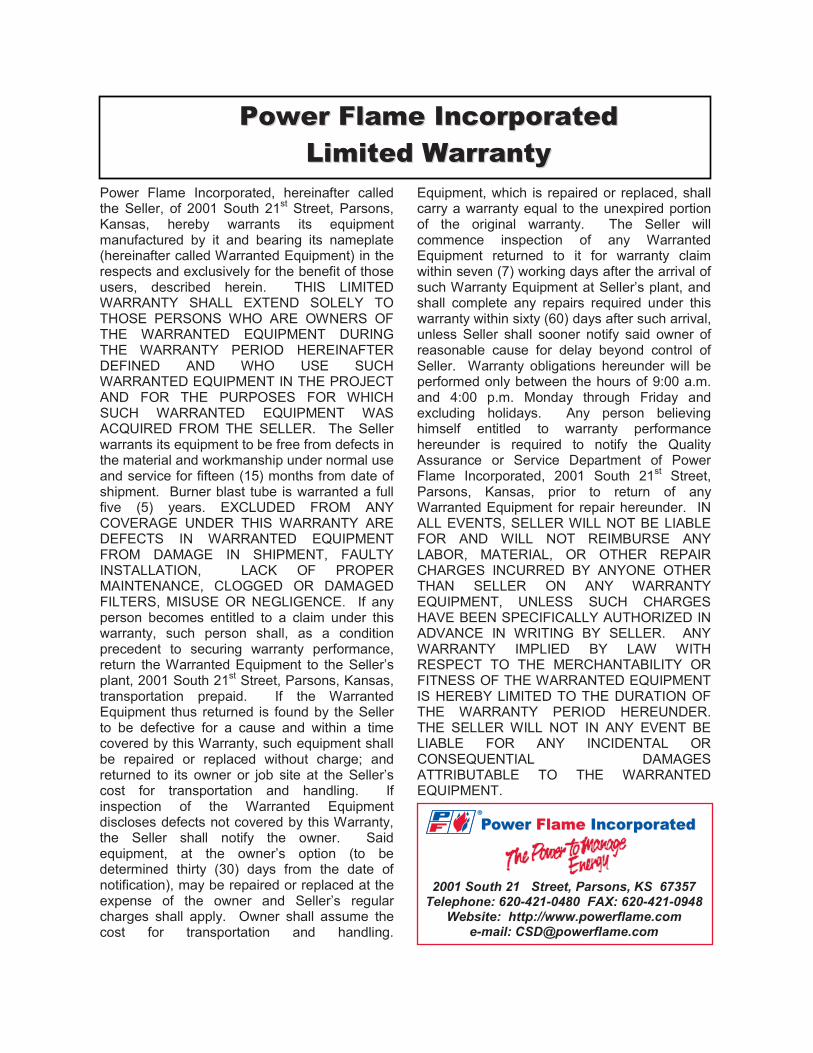
Power Flame Incorporated, hereinafter called the Seller, of 2001 South 21st Street, Parsons, Kansas, hereby warrants its equipment manufactured by it and bearing its nameplate (hereinafter called Warranted Equipment) in the respects and exclusively for the benefit of those users, described herein. THIS LIMITED WARRANTY SHALL EXTEND SOLELY TO THOSE PERSONS WHO ARE OWNERS OF THE WARRANTED EQUIPMENT DURING THE WARRANTY PERIOD HEREINAFTER DEFINED AND WHO USE SUCH WARRANTED EQUIPMENT IN THE PROJECT AND FOR THE PURPOSES FOR WHICH SUCH WARRANTED EQUIPMENT WAS ACQUIRED FROM THE SELLER. The Seller warrants its equipment to be free from defects in the material and workmanship under normal use and service for fifteen (15) months from date of shipment. Burner blast tube is warranted a full five (5) years. EXCLUDED FROM ANY COVERAGE UNDER THIS WARRANTY ARE DEFECTS IN WARRANTED EQUIPMENT FROM DAMAGE IN SHIPMENT, FAULTY INSTALLATION, LACK OF PROPER MAINTENANCE, CLOGGED OR DAMAGED FILTERS, MISUSE OR NEGLIGENCE. If any person becomes entitled to a claim under this warranty, such person shall, as a condition precedent to securing warranty performance, return the Warranted Equipment to the Seller’s plant, 2001 South 21st Street, Parsons, Kansas, transportation prepaid. If the Warranted Equipment thus returned is found by the Seller to be defective for a cause and within a time covered by this Warranty, such equipment shall be repaired or replaced without charge; and returned to its owner or job site at the Seller’s cost for transportation and handling. If inspection of the Warranted Equipment discloses defects not covered by this Warranty, the Seller shall notify the owner. Said equipment, at the owner’s option (to be determined thirty (30) days from the date of notification), may be repaired or replaced at the expense of the owner and Seller’s regular charges shall apply. Owner shall assume the cost for transportation and handling.
Equipment, which is repaired or replaced, shall carry a warranty equal to the unexpired portion of the original warranty. The Seller will commence inspection of any Warranted Equipment returned to it for warranty claim within seven (7) working days after the arrival of such Warranty Equipment at Seller’s plant, and shall complete any repairs required under this warranty within sixty (60) days after such arrival, unless Seller shall sooner notify said owner of reasonable cause for delay beyond control of Seller. Warranty obligations hereunder will be performed only between the hours of 9:00 a.m. and 4:00 p.m. Monday through Friday and excluding holidays. Any person believing himself entitled to warranty performance hereunder is required to notify the Quality Assurance or Service Department of Power Flame Incorporated, 2001 South 21st Street, Parsons, Kansas, prior to return of any Warranted Equipment for repair hereunder. IN ALL EVENTS, SELLER WILL NOT BE LIABLE FOR AND WILL NOT REIMBURSE ANY LABOR, MATERIAL, OR OTHER REPAIR CHARGES INCURRED BY ANYONE OTHER THAN SELLER ON ANY WARRANTY EQUIPMENT, UNLESS SUCH CHARGES HAVE BEEN SPECIFICALLY AUTHORIZED IN ADVANCE IN WRITING BY SELLER. ANY WARRANTY IMPLIED BY LAW WITH RESPECT TO THE MERCHANTABILITY OR FITNESS OF THE WARRANTED EQUIPMENT IS HEREBY LIMITED TO THE DURATION OF THE WARRANTY PERIOD HEREUNDER. THE SELLER WILL NOT IN ANY EVENT BE LIABLE FOR ANY INCIDENTAL OR CONSEQUENTIAL DAMAGES ATTRIBUTABLE TO THE WARRANTED EQUIPMENT.
2001 South 21 Street, Parsons, KS 67357 Telephone: 620-421-0480 FAX: 620-421-0948
Website: http://www.powerflame.com e-mail: [email protected]
DC4 DRAFT CONTROL
ENTERESC
®
DC4 DRAFT CONTROL
ENTERESC
®
Power Flame IncorporatedPower Flame Incorporated
Power Flame IncorporatedPower Flame Incorporated
DC4 DRAFT CONTROL
ENTERESC
®
FD & FDMInstallation and
Operation ManualInstallation and
Operation Manual
FD & FDMDC4 DRAFT CONTROL
ENTERESC
®®
Power Flame®


