18
FD-FM Series Optical Power Meters OPERATING INSTRUCTIONS Page 1

FD-FM SeriesOptical Power Meters
OPERATINGINSTRUCTIONS
Page 1

Fiberdyne Labs, Inc.FD-FM Series Optical Power MetersOperating Instructions
(315) 895-8470December 2001
Fiberdyne Labs, Inc. reserves the right to make changes to the material containedherein without notice and shall not be responsible for any changes caused by relianceon the material presented.
ST is a trademark of AT&T.Decnet is a trademark of DEC.NEC D4 is a trademark of NEC.
Page 2
ContentsGeneral ......................................................................... 5
Features......................................................................... 5
Applications.................................................................. 5
Safety............................................................................. 5
Precautions.................................................................... 6
LCD Display.................................................................. 6
Front Panel Operating Controls..................................... 8
Clearing Memory (FD-FM8520)................................... 11
Printing Stored Data (FD-FM8520).............................. 11
Uploading Stored Data to a PC (FD-FM8520).............. 12
Operation....................................................................... 12
Optical Power Verification............................................ 12
Optical Loss Measurement............................................ 13
Store Loss Measurement............................................... 15
Application Note (FD-FM8520).................................... 15
Maintenance.................................................................. 16
Battery Replacement..................................................... 16
Optional Battery Charger.............................................. 16
General Care.................................................................. 17
Customer Service.......................................................... 17
Repair............................................................................ 17
Technical Assistance..................................................... 17
Ordering Information..................................................... 18
Specifications................................................................ 18
Figures
1. 1. FD-FM8520 Front Panel..................................... 6
2. Optical Power Verification....................................... 14
3. Optical Loss Measurement........................................ 17
Page 3
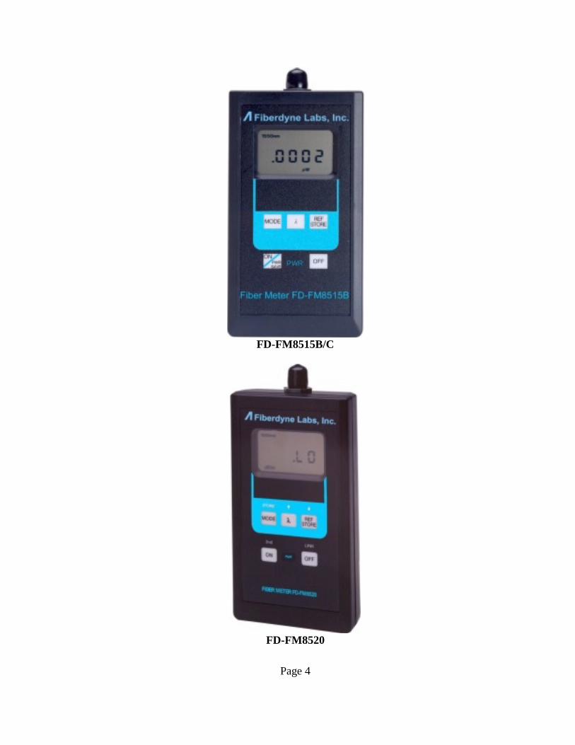
FD-FM8515B/C
FD-FM8520
Page 4

GeneralThank you for purchasing a Fiberdyne Labs Optical Power Meter. The lightweight,handheld Models FD-FM8515B/C & FD-FM8520 Optical Power Meters are precisionmeters in a pocket size case.
Models FM8515B/C and FM8520 are calibrated at the standard wavelengths of 850,1310 and 1550 nm.
Models FM8515B and FM8520 can measure absolute power in dBm, and microwatts( W) along with attenuation (relative power) as dBr. Model FD-FM8515C canmeasure absolute power in dBm, and milliwatts (mW) along with attenuation(relative power) as dBr.
Features• Calibrated at 850, 1310, and 1550 nm (Models FD-FM8515B/C and FD-FM8520)• +5 to -70 dB dynamic range (FD-FM8515B, FD-FM8520)• +23 to -50 dB dynamic range (FD-FM8515C)• 250 Stored Readings per wavelengths (FD-FM8520)• 2 kHz Modulation detection (FD-FM8520)• Reference store facility (FD-FM8515B/C, FD-FM8520)• RS-232 Output for Printer / PC Upload (FD-FM8520)• Measurements in dBm, dBr, and microwatts (FD-FM8515B, FD-FM8520)• > 100 hours of battery life• Adapter caps for SC, FC, and ST connectors
Applications• Cable and Link Loss Measurement• Network Auditing and Maintenance• Troubleshooting and Repair• Connector and Coupling Losses• Field Test and Repair• Bare Fiber Loss Measurement• Transceiver Output Level
SafetyNOTE: This equipment has been tested and found to comply with the limits for aClass A digital device, pursuant to Part 15 of the FCC Rules. These limits aredesigned to provide reasonable protection against harmful interference whenequipment is operated in a commercial environment. This equipment generates, uses,and can radiate radio frequency energy, and if not installed and used in accordancewith the instruction manual, may cause harmful interference to radio communications.Operation of this equipment in a residential area is likely to cause harmful interferencein which case the user will be required to correct the interference at his own expense.
Page 5
PrecautionsUse care when working with any optical transmission equipment. It is good practiceto avoid looking directly at any optical fibers or optical sources. Always refer to yourcompany's safety procedures when working with optical systems.It is important to keep all optical connections and surfaces free from dirt, oils or othercontamination to ensure proper operation. This applies to all connectors that areconnected to the optical port on any one of the Fiber Meters. Scratched orcontaminated connectors can reduce system performance. Refer to your companypractices for cleaning optical connectors. Always replace the protective dust cap afteruse.
LCD Display
The Optical Power Meter's LCD display has large characters to view measurements.Out-of-range inputs are shown via a "OVERRANGE" indicator.
The LCD display includes operating modes; dBm, dBr, W, (mW FD-FM8515C),and REFSTORE (FD-FM8515B/C, FD-FM8520). Enunciators for low batterycondition, signal over range, selected wave-length, measured results, 2 kHzmodulation indicator (FD-FM8520).
For an optical power measurement less than -70 dBm (FD-FM8515B, FD-FM8520)or less than -50 dBm (FD-FM8515C), the LCD display will read ".LO". A"LOWBATT" warns the operator that battery power is low.
When the Optical Power Meter is first turned on, all segments of the LCD display areactivated for approximately 1 second. This is a self test of the on-boardmicrocontroller based measurement and display system. The self test is then followedby a 2 second display of the software version code. After this start-up sequence, theinstrument is stabilized and ready to use.
Page 6

Page 7

Front Panel Operating Controls
Note: Fiberdyne Labs Models FD-FM8515B/C and FD-FM8520 have some of thesame features. The front panel drawing of the FD-FM8520 was selected because ithas all the features of all the other Fiberdyne Power Meters plus storage, and a RS-232interface. Figure 1 is for reference purposes only.
FD-FM8515B/C, FD-FM8520
Universal Adapter Mount - the threaded mount allows the connection of variousadapter caps for the acceptance of the required fiber optic connectors. Adapter caps,purchased separately, convert the threaded mount to the required connector style.
FD-FM8515B
Liquid Crystal Display (LCD) - When the Power Meter is first powered ON, allsegments of the display are illuminated as a self test. Measurements are displayed inabsolute power (dBm), loss (dBr), and microwatts ( W), with enunciators definingwavelength, LOWBATT (low battery), OVERRANGE (when > +5 dBm ismeasured), and REF (indicates referenced value for loss measurement).
FD-FM8515C-High Power -Liquid Crystal Display (LCD)
When the Power Meter is first powered ON, all segments of the display areilluminated as a self test. Measurements are displayed in absolute power (dBm), loss(dBr), and milliwatts (mW), with annunciators defining wavelength, LOWBATT(low battery), OVERRANGE (when >+23 dBm is measured), and REF (indicatesreferenced value for loss measurement).
FD-FM8520 - Liquid Crystal Display (LCD)
When the Power Meter is first powered ON, all segments of the display areilluminated as a self test. Measurements are displayed in absolute power (dBm), low(dBr), and microwatts ( W), with annunciators defining wavelength, LOWBATT (lowbattery), MODULATION (detection of 2-kHz signal), OVERRANGE (when >+5dBm is measured), REF (indicates referenced value for loss measurement), andSTORE (storage of current measurement).
Page 8
1
2
2
2

FD-FM8520 -
The STORE function is a 2nd key function of the MODE key and is activated bydepressing the ON key a second time. The STORE annunciator is displayedindicating that the FD-FM8520 is in the 2nd function mode. While in the STORE1
mode, measurements can be stored by depressing the STORE key.
1. While in the STORE mode, the FD-FM8520 cannot be turned off.
FD-FM8515B/C & FD-FM8520 -
Each press of the MODE key cycles between dBm, dBr, W or mW, and REFmeasurement mode.
FD-FM8520 -Serial Port -
This connector is used for printing or transferring stored data measurements. Storeddata can be printed to an optional printer or imported into a PC spreadsheet such asMicrosoft Excel for data analysis.
FD-FM8515B/C, FD-FM8520 -Battery Charger Input -
This optional feature is used when the power meter is ordered with NiCadrechargeable batteries.
FD-FM8520 -
A second (2nd) function of each key is available on the front panel. The 2nd function isactivated by depressing the ON key again after the FD-FM8520 has been poweredON, and the display has completed its self-test. The STORE annunciator indicatesthat the 2nd function is activated.
Page 9
3
4
5
6
7
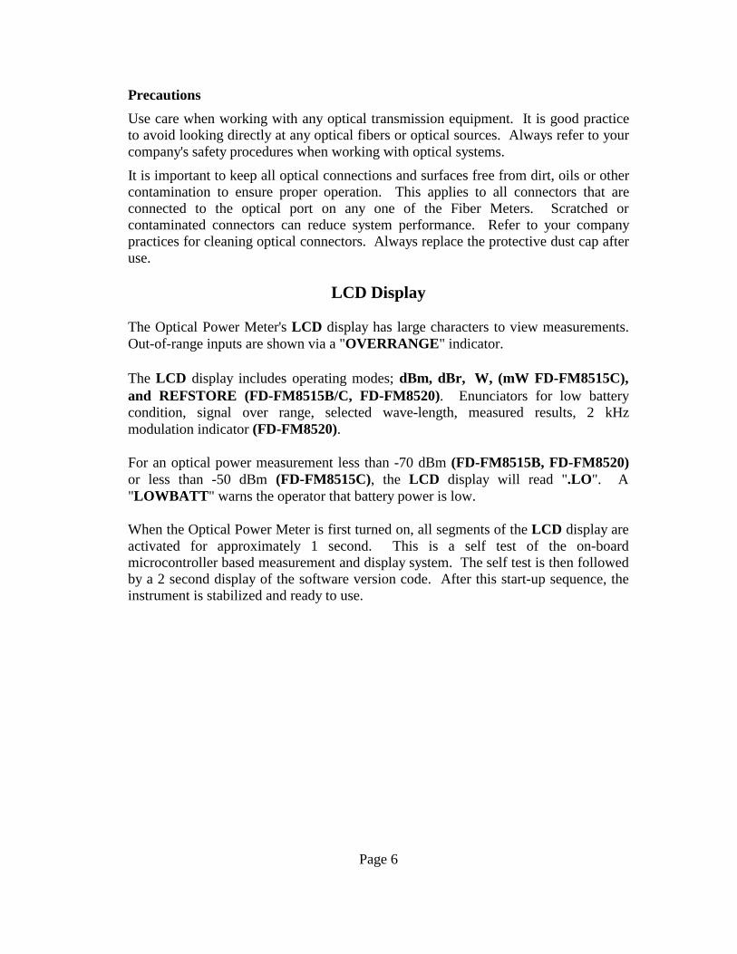
FD-FM8515B/C -
When depressing the ON key once, the unit powers on. During this power on cycle,the display does a self-check of all its segments. If no keys are pressed for 5 minutes,the power meter automatically powers off to conserve battery life.
FD-FM8520 -
When depressing the ON key once, the FD-FM8520 powers on. During this power oncycle, the display does a self-check of all its segments. When depressing the ON keya second time, the FD-FM8520 enters into its 2nd key function state by displaying theSTORE annunciator. If no keys are pressed for 5 minutes, the FD-FM8520automatically powers off to conserve battery life.
FD-FM8520 -
The function is considered a 2nd key function. Each time this key is depressed thestorage location increments. When holding down the key, the display will show thestorage location number, and then upon release of the key, the stored value will bedisplayed.
FD-FM8520 -
The function is considered a 2nd key function. Each time this key is depressed thestorage location will decrement. When holding down the key, the display will showthe storage number, and upon the release of the key, the stored value will bedisplayed.
FD-FM8515B/C, FD-FM8520 -
Depressing the REF STORE key will store the current dBm value displayed as areference power level.
FD-FM8515B/C, FD-FM8520 -
The Greek letter lambda ( ) denotes wavelength. 1550, 1300 and 850nm wavelengthsare available. Depressing this key will select the desired wavelength on the powermeter.
Page 10
8
8
9
10
11
12

FD-FM8520 -
The LINK function is considered a 2nd key function. When this key is depressed, theSERIAL port is activated, and the r232 annunciator is displayed.
FD-FM8515B/C, FD-FM8520 -
Depressing the OFF key will turn off the power meter.
Operating Procedures
Clearing Memory (Applies to Model FD-FM8520 only):
CLEAR All Locations: Stored data in all locations can be CLEARED by depressingand holding the ON key a second time (the STORE annunciator will be displayedindicating that the 2nd key function is enabled), and the STORE key simultaneouslyfor 5 seconds. The stored location counter will decrement to location 1, indicatingthat stored data in all locations has been cleared. The CLEAR function applies towhichever wavelength is selected at the time.
CLEAR Selected Location: Stored data in a selected location can be over written byaccessing that location using the or keys. The STORE annunciator should bedisplayed indicating that the 2nd key function is enabled. Depress and hold both theSTORE key, and the key simultaneously until the new value is displayed.Printing Stored Data (Applies to Model FD-FM8520 only):
The FD-FM8520 must be connected to the Printer using the interface cable supplied.The FD-FM8520 transmits at: 9600 baud, 8 data bits, 1 stop bit, no parity,XON/XOFF.
The STORE annunciator should be displayed indicating that the 2nd key function isenabled. Depress the LINK key and the r232 annunciator will display. Then depressthe key, and the STORE annuciator will blank out, indicating that the stored data hasbeen sent to the printer. The following is an example of the printout:
Fiberdyne Labs, Inc. FM8520 Fiber MeterFiber Optic Measurement Report
LOC.# READINGS LAMDA------- ----------- ---------
1 -9.01 dBm 1550nm2 -12.01 dBm 1550nm3 -9.01 dBm 1550nm
Page 11
13
14
Uploading Stored Data to a Spreadsheet (Applies to Model FD-FM8520 only):
Connect the FD-FM8520 to an available COM port on a PC using the interface cablesupplied. The PC must contain a third party communications program. An examplewould be : Windows Hyper Terminal. The FD-FM8520 transmits at: 9600 baud, 8data bits, 1 stop bit, no parity, XON/XOFF. The STORE annunciator should bedisplayed indicating that the 2nd key function is enabled. Depress the LINK key andthe r232 annunciator will be displayed. Then depress the key, and the STOREannuciator will blank out, indicating that the stored data has been sent to the PC.
Operation
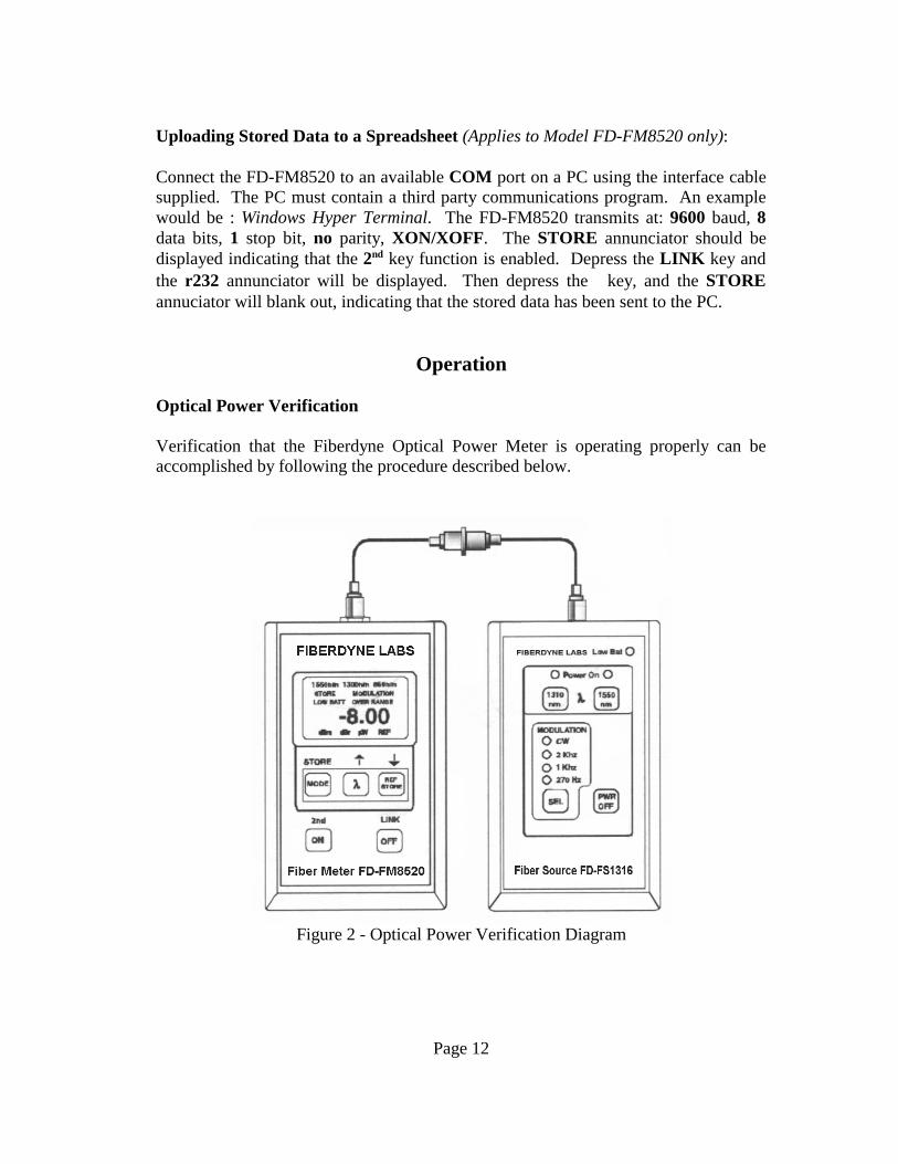
Optical Power Verification
Verification that the Fiberdyne Optical Power Meter is operating properly can beaccomplished by following the procedure described below.
Figure 2 - Optical Power Verification Diagram
Page 12
• Clean all optical ports and connectors according to your company procedures.• Connect a patch cable to the Fiberdyne Optical Power Meter.• Connect a patch cable to a light source such as Fiberdyne's Model FD-FS1316
Laser Light Source.• Connect the ends of the patch cables together using a coupling device.• Turn on the Fiberdyne Laser Light Source and set to 1310nm. The unit will
stabilize very quickly.• Turn on the Fiberdyne Optical Power Meter and set the wavelength to 1310nm.• Adjust the output of the Fiberdyne Laser Source until the Fiberdyne Power Meter
reads -08.0 dBm. (Note: The launch output power of the Fiberdyne Laser Source is-08.0 dBm with an output adjust control of 1.0 dB.)
• Record the power meter reading. This measurement will be the reference level.
Note: An important consideration is the wavelength of the optical signal. Both theLaser Source and the Power Meter must be set at the same wavelength to ensureaccurate measurements. The above example describes 1310nm testing. To test1550nm or 850nm, simply set both the Fiberdyne Laser Source and the FiberdynePower Meter to either 1550nm or 850nm.
Optical Loss Measurements• Verify the optical power and either record the reading, of if the power meter is a
Fiberdyne Model FD-FM8515B/C, or FD-FM8520, simply depress the REFSTORE Key while in the dBm MODE, and the power measurement will be storedautomatically.
• Disconnect the patch cables at the coupling. Be sure not to disturb the connectionat the end of the Fiberdyne Fiber Laser Source or the Fiberdyne Power Meter. Thisis to ensure accurate measurements.
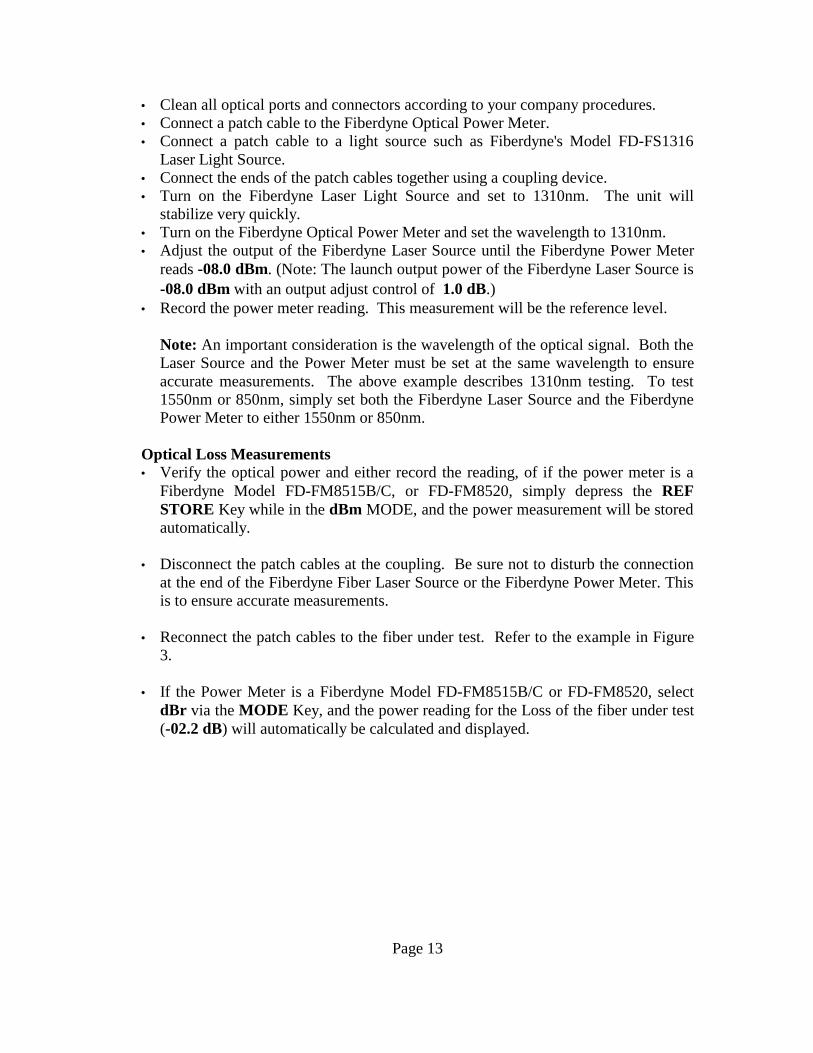
• Reconnect the patch cables to the fiber under test. Refer to the example in Figure3.
• If the Power Meter is a Fiberdyne Model FD-FM8515B/C or FD-FM8520, selectdBr via the MODE Key, and the power reading for the Loss of the fiber under test(-02.2 dB) will automatically be calculated and displayed.
Page 13
Figure 3 - Optical Loss Measurement Diagram
Page 14

Store Loss Measurement: (Applies to Model FD-FM8520 only)
• The current dBr (relative) measurement can be stored by:
1. depressing the ON key which activates the 2nd key function ( the STOREannunciator will illuminate), and then
2. depressing the STORE key. When the STORE key is depressed, the FD-FM8520automatically reverts back to its primary key function mode.
• To store another measurement:1. depress the ON key, and then2. depress the STORE key. The FD-FM8520 automatically increments to the next
storage location.
Notes:
1. The FD-FM8520 will not display a stored dBr measurement in the W MODE. This is indicated bydashes in the display.
2. When displaying a stored dBr measurement in the dBm MODE, the dBr annunciator flashesindicating the measurement is in dBr.
3. When displaying a stored dBm measurement in the dBr MODE, the dBr annunciator flashesindicating the measurement is in dBm.
4. When displaying a stored W measurement in the dBr MODE, the dBm annunciator flashesindicating the measurement is in dBm.
Application NoteHyper Terminal Setup: (Applies to Model FD-FM8520 only)
Most communication programs will communicate with the FD-FM8520 OpticalPower Meter. This note will describe Hyper Terminal which is standard withMicrosoft Windows 95/98.
Step 1 - From the Windows Toolbar, click on "START" select "PROGRAMS",select "ACCESSORIES", select "COMMUNICATIONS", then "click" on "HYPERTERMINAL". The Hyper Terminal folder will now be open.
Step 2 - Double "click" the "Hypertrm.exe" ICON. This will open the HyperTerminal application program.
Step 3 - The Connection Description dialog box will now appear. Enter a name to beused (such as FD-FM8520), and select the desired ICON. After this is done enter OK.
Step 4 - The Connect To dialog box will now appear. Under the "Connect using"
Page 15

drop down menu box, select the appropriate "Direct to COM Port". After this isdone enter OK.
Step 5 - The COM Port Properties dialog box will now appear. Select the followingunder "Port Settings":
Bits per second = 9600Data Bits = 8Parity = NoneStop Bits = 1Flow Control = Xon/Xoff
After the above have been selected, enter OK.
Step 6 - The Hyper Terminal window will now appear with the name that you selectedin Step 3. In this example it is (FD-FM8520 - Hyper Terminal).
Step 7 - All the COM port property settings that were previously entered, plus theICON that was selected in Step 2 can be saved while in the FD-FM8520 - HyperTerminal window by selecting File, then "clicking" on Save.
Step 8 - Connect the supplied RS-232 interface cable from the Fiberdyne FD-FM8520to your computer. Note: Typically, the Serial/COM ports on computers are MALE.
Maintenance
Battery ReplacementThe Fiber Meters require no periodic maintenance other than replacing the batteries.Under normal use the two AA alkaline batteries should provide greater than 100 hoursof continuous use. To replace battery, place the unit with its back side facing up. Usea small screwdriver to remove the two screws and release the battery cover. Install thebattery and then secure the cover to the unit with screws.
Optional Battery ChargerWhen the Fiber Meters are purchased with the optional battery charger, they areshipped with two AA NiCad rechargeable batteries. The batteries have been kept inthe uncharged state for shipment. Therefore, be sure to fully charge them before use.
To charge the batteries, simply plug the charger's transformer into an AC outlet andthe other end into the charger jack on the fiber meter. Charge the unit overnight(about 14 hours). The batteries may be charged with any battery charger with thefollowing specifications:
Page 16

INPUT AC 120V~, 60Hz in the USA and CanadaAC 110-240 V~, 50/60 Hz in other countries
OUTPUT 8.7-15 V AC or DC @ > 150mA2.1 mm coax jack (Tip – Positive)
Important – When charging batteries in the unit, please be sure to use only NiCadbatteries. Charging any other type of battery will cause damage to the unit.
General CareTo avoid damage to the Optical Power Meters, do not use cable connectors that aredirty or faulty. A dust cap is provided for the optical output port, and should be inplace when the unit is not in use to prevent foreign material from entering the port. Itis best to clean the connectors first, using cotton swabs and isopropyl alcohol.
To clean the inside of the optical connector, use only a small diameter cotton swablightly moistened with isopropyl alcohol.
Clean the Optical Power Meter's body with a damp cloth. Do not use solvents orabrasives.
CalibrationThe recommended calibration interval on the Fiberdyne FD-FM Series of OpticalPower Meters is every 2 years. Fiberdyne Lab's calibration service is N.I.S.T.Traceable and properly equipped to calibrate these meters.
Customer ServiceRepairIf repair of any of the Fiberdyne Optical Power Meters is necessary, return the unit inaccordance with the warranty instructions in the back of this manual to the addresslisted below.
Fiberdyne Labs, Inc.127 Business Park DriveFrankfort, New York 13340Tel: (800) 894-9694Fax: (315) 895-8436
Technical AssistanceShould you need technical assistance with any of the Optical Power Meters, contactApplications Engineering at the following telephone numbers:
Toll-free: 1-800-894-9694 --or-- Outside the USA 001-315-895-8470
Page 17

Ordering InformationOrders for any of the Fiberdyne Optical Power Meters, and any of their accessoriesshould be directed to the address shown above.
MODELS FD-FM8515B/C & FD-FM8520Detector Type InGaAs (FD-FM8515B, FD-FM8520)
Filtered InGaAs (FD-FM8515C)Power Range -5 to -70 dBm (FD-FM8515B, FD-FM8520)
+23 to -50 dBm (FD-FM8515C)Calibration Wavelength 850, 1310, & 1550nmAccuracy +/- .25dB (measured at 23°C, 1310nm @ -20dBm)Resolution 0.01dBDisplay Indicators 4 Digit LCDLow Battery Indicator Visual indicatorSignal Overange Visual indicatorModulation - 2kHz Visual indicator (FM8520)Battery Life (Alkaline) >100 hrs. continuous useAdapter Caps ST, FC, SC, & UniversalPower Two AA-Size Alkaline or NiCad (opt.)NiCad Charger (opt.) 8.7-15 VAC/DC >150mA – Tip PositiveOperating Temp.Storage Temp.
0°C to +40°C-20°C to +60°C
Size 6.3”H x 3.3”W x 1.3”D (160 x 83 x 33mm)Weight 0.49 lbs (220g)
This document and others can be found on our Internet Webpage at:http://www.fiberdyne.com/techinfo/index1.html
Additonal Fiberdyne Labs, Inc. prodcuts and services may also be viewed andpurchased on our Internet Webpage at:http://www.fiberdyne.com
Page 18


![Complete Range of Optical Tensiometers Contact Angle Meters · Attension I Theta I Optical Tensiometers / Contact Angle Meters [7] OneAttension software OneAttension software combines](https://static.documents.pub/doc/80x56/5ee1a298ad6a402d666c7149/complete-range-of-optical-tensiometers-contact-angle-meters-attension-i-theta-i.jpg)


