40
FD Series HYUNDAI WIA Column Moving Type Vertical Machining Center

FD SeriesHYUNDAI WIA Column Moving Type Vertical Machining Center

The Vertical Machining Center FD Series designed by Hyundai WIA with years of expertise and the latest technology, is a column moving type machining center equipped with Dual Table to maximize productivity.
Technical Leader
●:Standard○:Option
MODELY-AxisStroke Spindlerpm Taper Magazine
410mm(16.1″)
460mm(18.1″)
600mm(23.6″) 8,000 10,000 12,000 BT40 24TOOL 30TOOL
F410D ● ●/○ ● ●
F500D ● ● ○ ○ ● ● ○
F600D ● ● ○ ● ● ○

High productivity Dual Table equippedHigh tech column moving Machining Center
FD Series● High precision main spindle designed with P4 Angular Contact Ball Bearings
● High power/torque main spindle for heavy duty cutting
● Dual Tables for enhanced productivity
● Latest Servo ATC for the fastest tool change time in the class
● Combination of Roller Type LM Guide and Box Guide for optimal feed (F500D)
● Roller Type LM Guide on all axes for high precision heavy cutting (F600D)
● Latest SIEMENS 828D Controller with wide range of support software

01 F410D BasicFeaturesHigh Speed & Productivity Vertical Machining Center
FD Series
LM GuidewayF410D Ball Type LM Guide provides reduction of noise while in motion, and reduction of non-cutting time due to superior travel speed.
Dual TableHigh speed 180º index rotating table increases productivity by providing the ability to load and unload on the outer table while processing on the other table.
Double Anchored Ball screwIn order to eliminate thermal growth and increase accuracy, all axes are driven by high precision double anchored ballscrews.
The double anchored and pretensioned design provides outstanding positioning and repeatability with virtually no thermal growth.
Directly Coupled Servo MotorEach axis is directly connected to a highly reliable digital servo motor to provide high rigidity and minimal thermal displacement.
04
02
01
03
Moving ColumnThe F410D is designed with a moving column in order to maximize productivity of the incorporated Dual Table. In addition, due to the enlargement of the column's width and symmetrical heat behavior column structure, heat displacement is minimized and machining accuracy is increased.
255
(10″)
180(7″)
410 (16.1″)
Ø12
00 (Ø
47.2
″)
650 (25.6″)
562 (22.1″)35 (1.3″)
R280 (11″)
TLM (Opt.)Interference Area
500
(19.
7″)
356
(14)
420
(16.
5″)
114
(4.4
8″)
500 (
19.7″
)
700 (27.5″)
500
(19.
7″)
355
(13.
9″)1
45(5
.7″)
30 (1.2
″)
R305 (12″)R75 (2.9″)
650 (25.6″)
900 (35.4″)
500
(19.
7″)
115
(3.5
″)
174(6.9″)67.8
(2.7″)
W.T (90mm-3.5″) R275 (10.8″)W.O (150mm-5.9″) R305 (12″)
◉ Table Size (L×W) : 2-650×410 mm (2-25.6″×16.1″)
◉ Max. Load Capacity : 2-250 kg (2-551.2 lb)
◉ Table Change Time : 5.2 sec

04+
05
FD
Ser
ieS
Vert
ical
Mac
hini
ng C
ente
rH
YUN
DAI
WIA
MAC
HIN
E TO
OL
Basic Features
01
03
04
02
05
05
ATC Speed Improvement
19% reduction 8% reduction
Before
After
Before
After
1.6 sec 3.8 sec
1.3 sec 3.5 sec
Tool to Tool Time Chip to Chip Time
◉ Rapid Traverse Rate (X/Y/Z axis) : 36/36/30 m/min (1,417/1,417/1,181 ipm)
◉ Spindle Speed : 10,000 Belt [10,000 Belt] rpm
◉ Spindle Output(Max./Cont.) : 18.5/15 [22.5/15] kW (24.8/20 [30.2/20] HP)
◉ Travel(X/Y/Z axis) : 570/410/580 mm (22.4″/16.1″/22.8″)
◉ Spindle Torque (Max./Cont.) : 117.7/95.4 [189/126] N.m (86.8/70.4 [139.4/92.9] lbf.ft)
[SIEMENS]

02 F500D BasicFeaturesHigh Speed & Productivity Vertical Machining Center
FD Series
Dual TableHigh speed 180º index rotating table increases productivity by providing the ability to load and unload on the outer table while processing on the other table.
Hybrid Type SlidewayEach axis on F500D is designed with slideways optimized to the axis. Sturdy Box Guide on Z-axis for heavy loads, and Roller Type LM Guides on X and Y axis for optimal travel ability.
04
02
01
03
◉ Table Size (L×W) : 2-700×500 mm (2-27.6″×19.7″)
◉ Max. Load Capacity : 2-350 kg (2-771.6 lb)
◉ Table Change Time : 6 sec
Moving ColumnThe F500D is designed with a moving column in order to maximize productivity of the incorporated Dual table. In addition, due to the enlargement of the column's width and symmetrical heat behavior column structure, heat displacement is minimized and machining accuracy is increased.
255
(10″)
180(7″)
410 (16.1″)
Ø12
00 (Ø
47.2
″)
650 (25.6″)
562 (22.1″)35 (1.3″)
R280 (11″)
TLM (Opt.)Interference Area
500
(19.
7″)
356
(14)
420
(16.
5″)
114
(4.4
8″)
500 (
19.7″
)
700 (27.5″)
500
(19.
7″)
355
(13.
9″)1
45(5
.7″)
30 (1.2
″)
R305 (12″)R75 (2.9″)
650 (25.6″)
900 (35.4″)
500
(19.
7″)
115
(3.5
″)
174(6.9″)67.8
(2.7″)
W.T (90mm-3.5″) R275 (10.8″)W.O (150mm-5.9″) R305 (12″)
Double Anchored Ball screwIn order to eliminate thermal growth and increase accuracy, all axes are driven by high precision double anchored ballscrews.
The double anchored and pretensioned design provides outstanding positioning and repeatability with virtually no thermal growth.
Directly Coupled Servo MotorEach axis is directly connected to a highly reliable digital servo motor to provide high rigidity and minimal thermal displacement.
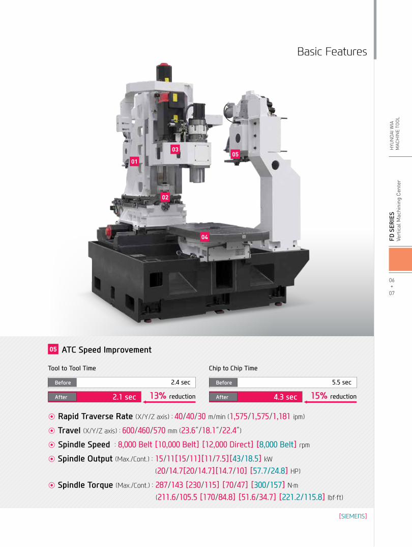
◉ Rapid Traverse Rate (X/Y/Z axis) : 40/40/30 m/min (1,575/1,575/1,181 ipm)
◉ Travel(X/Y/Z axis) : 600/460/570 mm (23.6″/18.1″/22.4″)
◉ Spindle Speed : 8,000 Belt [10,000 Belt] [12,000 Direct] [8,000 Belt] rpm
◉ Spindle Output(Max./Cont.) : 15/11[15/11][11/7.5][43/18.5] kW
(20/14.7[20/14.7][14.7/10] [57.7/24.8] HP)
◉ Spindle Torque (Max./Cont.) : 287/143 [230/115] [70/47] [300/157] N.m
(211.6/105.5 [170/84.8] [51.6/34.7] [221.2/115.8] lbf.ft)
06+
07
FD
Ser
ieS
Vert
ical
Mac
hini
ng C
ente
rH
YUN
DAI
WIA
MAC
HIN
E TO
OL
Basic Features
01
02
03
04
05
05 ATC Speed Improvement
13% reduction 15% reduction
Before
After
Before
After
2.4 sec 5.5 sec
2.1 sec 4.3 sec
Tool to Tool Time Chip to Chip Time
[SIEMENS]

255
(10″)
180(7″)
410 (16.1″)
Ø12
00 (Ø
47.2
″)
650 (25.6″)
562 (22.1″)35 (1.3″)
R280 (11″)
TLM (Opt.)Interference Area
500
(19.
7″)
356
(14)
420
(16.
5″)
114
(4.4
8″)
500 (
19.7″
)
700 (27.5″)
500
(19.
7″)
355
(13.
9″)1
45(5
.7″)
30 (1.2
″)
R305 (12″)R75 (2.9″)
650 (25.6″)
900 (35.4″)
500
(19.
7″)
115
(3.5
″)
174(6.9″)67.8
(2.7″)
W.T (90mm-3.5″) R275 (10.8″)W.O (150mm-5.9″) R305 (12″)
03 F600D BasicFeaturesHigh Speed & Productivity Vertical Machining Center
FD Series
Dual TableHigh speed 180º index rotating table increases productivity by providing the ability to load and unload on the outer table while processing on the other table.
Roller Type LM GuideThe travel mechanism on F600D is equipped with Roller Type LM Guide for rigidity and reducing idle time.
04
02
01
03
◉ Table Size (L×W) : 2-900×650 mm (2-35.4″×25.6″)
◉ Max. Load Capacity : 2-400 kg (2-881.8 lb)
◉ Table Change Time : 8.5 sec
Moving ColumnThe F600D is designed with a moving column in order to maximize productivity of the incorporated Dual table. In addition, due to the enlargement of the column's width and symmetrical heat behavior column structure, heat displacement is minimized and machining accuracy is increased.
Rapid Traverse Rate42 m/min(1,653.5 ipm)
Double Anchored Ball screwIn order to eliminate thermal growth and increase accuracy, all axes are driven by high precision double anchored ballscrews.
The double anchored and pretensioned design provides outstanding positioning and repeatability with virtually no thermal growth.
Directly Coupled Servo MotorEach axis is directly connected to a highly reliable digital servo motor to provide high rigidity and minimal thermal displacement.
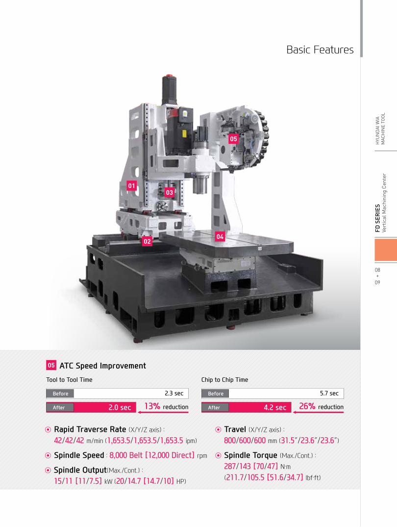
◉ Rapid Traverse Rate (X/Y/Z axis) :
42/42/42 m/min (1,653.5/1,653.5/1,653.5 ipm)
◉ Spindle Speed : 8,000 Belt [12,000 Direct] rpm
◉ Spindle Output(Max./Cont.) : 15/11 [11/7.5] kW (20/14.7 [14.7/10] HP)
◉ Travel(X/Y/Z axis) :
800/600/600 mm (31.5″/23.6″/23.6″)
◉ Spindle Torque (Max./Cont.) : 287/143 [70/47] N.m
(211.7/105.5 [51.6/34.7] lbf.ft)
08+
09
FD
Ser
ieS
Vert
ical
Mac
hini
ng C
ente
rH
YUN
DAI
WIA
MAC
HIN
E TO
OL
Basic Features
0103
04
05
02
05 ATC Speed Improvement
13% reduction 26% reduction
Before
After
Before
After
2.3 sec 5.7 sec
2.0 sec 4.2 sec
Tool to Tool Time Chip to Chip Time

Belt Type SpindleThe FD Series is equipped with a Belt Type Spindle to ease maintenance and minimize machining noise.
The main spindle is designed with P4 Angular Contact Ball Bearings to assure quality during high speed processing, also to stabilize high precision even over long periods of machining.
04 High Precision SpindleLong Lasting High Accuracy & Excellent PerformanceVertical Machining CenterFD Series

Through Spindle CoolantThrough Spindle Coolant is exceedingly useful when drilling deep holes. It helps increase the lifetime of the tool, while decreasing cycle time.
20 bar/30 bar/70 bar(290 psi/435 psi/1,015 psi)
Spindle Cooling The spindle cooling system minimizes thermal displacement which can happen during lengthy machining operations, and offers continued accuracy based on the thermal stability.
10+
11
FD
Ser
ieS
Vert
ical
Mac
hini
ng C
ente
rH
YUN
DAI
WIA
MAC
HIN
E TO
OL
Spindle
Direct Type Spindle (F500D/600D)The spindle motor is directly connected to the main spindle by a high speed and high precision coupling.Rapid spindle acc/deceleration is performed without backlash. The coupling also minimizes vibration and heat transfer from the motor preventing thermal displacement.
◉ Spindle Speed : 12,000 rpm
◉ Spindle Taper : NT #40
BT
CAT
Tool Holders

1PH8 Spindle MotorThe 1PH8 Series Motor is a high quality and performance motor with the characteristics of maximum concentricity of 10㎛ and short driving time.
Power (kW[HP])
Spindle Speed (r/min)
Torque (N∙m[lbf∙ft]) Power (kW[HP])
Spindle Speed (r/min)
Torque (N∙m[lbf∙ft])
Power (kW[HP])
Spindle Speed (r/min)
Torque (N∙m[lbf∙ft]) Power (kW[HP])
Spindle Speed (r/min)
Torque (N∙m[lbf∙ft])
18.5[24.8]
15[20]
15[20]
11[14.7]
15[20]
11[14.7]
11[14.7]
7.5[10]
0 1,500 7,000 12,000
0
0 625 937 7,500 10,000
0 500 750 6,000 8,0001,500 4,000 10,000
117.7[86.8]
287[211.7]
143[105.5]
95.4[70.4]
230[170]
115[84.8]
70[51.6]
47[34.7]
44.1[32.5]35.8[26.4]
18.5kW[24.8HP] (30min S3 60%)
117.7N∙m[86.8lbf∙ft] (30min S3 60%)15kW[20HP] (3Cont.)
15kW[20HP] (30min S3 60%)
11kW[14.7HP] (3Cont.)
15kW[20HP] (30min S3 60%)
11kW[14.7HP] (3Cont.)
11kW[14.7HP] (30min S3 60%)
7.5kW[10HP] (3Cont.)
95.4N∙m[70.4lbf∙ft] (Cont.)
70N∙m[51.6lbf∙ft] (30min S3 60%)47N∙m[34.7lbf∙ft] (Cont.)
230N∙m[170lbf∙ft] (30min S3 60%)
115N∙m[84.8lbf∙ft] (Cont.)
287N∙m[211.7lbf∙ft] (30min S3 60%)
143N∙m[105.5lbf∙ft] (3Cont.)
Power (kW[HP])
Spindle Speed (r/min)
Torque (N∙m[lbf∙ft]) Power (kW[HP])
Spindle Speed (r/min)
Torque (N∙m[lbf∙ft])
Power (kW[HP])
Spindle Speed (r/min)
Torque (N∙m[lbf∙ft]) Power (kW[HP])
Spindle Speed (r/min)
Torque (N∙m[lbf∙ft])
18.5[24.8]
15[20]
15[20]
11[14.7]
15[20]
11[14.7]
11[14.7]
7.5[10]
0 1,500 7,000 12,000
0
0 625 937 7,500 10,000
0 500 750 6,000 8,0001,500 4,000 10,000
117.7[86.8]
287[211.7]
143[105.5]
95.4[70.4]
230[170]
115[84.8]
70[51.6]
47[34.7]
44.1[32.5]35.8[26.4]
18.5kW[24.8HP] (30min S3 60%)
117.7N∙m[86.8lbf∙ft] (30min S3 60%)15kW[20HP] (3Cont.)
15kW[20HP] (30min S3 60%)
11kW[14.7HP] (3Cont.)
15kW[20HP] (30min S3 60%)
11kW[14.7HP] (3Cont.)
11kW[14.7HP] (30min S3 60%)
7.5kW[10HP] (3Cont.)
95.4N∙m[70.4lbf∙ft] (Cont.)
70N∙m[51.6lbf∙ft] (30min S3 60%)47N∙m[34.7lbf∙ft] (Cont.)
230N∙m[170lbf∙ft] (30min S3 60%)
115N∙m[84.8lbf∙ft] (Cont.)
287N∙m[211.7lbf∙ft] (30min S3 60%)
143N∙m[105.5lbf∙ft] (3Cont.)
Power (kW[HP])
Spindle Speed (r/min)
Torque (N∙m[lbf∙ft])
22.5kW[30.2HP] (S6-40%)
15[20]
22.5[30.2]
10,0001,350 2,800 3,500
126[92.9]
189[139.4]
15kW[20HP] (Cont.)189N∙m[139.4lbf∙ft] (S6-40%)
126N∙m[92.9lbf∙ft] (Cont)
Power (kW[HP])
Spindle Speed (r/min)
Torque (N∙m[lbf∙ft])
18.5[24.8]
43[57.7]
8,0001,500
157[115.8]
300[221.2]43kW[57.7HP] (S6-40%)
18.5kW[24.8HP] (Cont.)
300N∙m[221.2lbf∙ft] (S6-40%)
157N∙m[115.8lbf∙ft] (Cont)
FANUC Spindle
F410D (10,000r/min, Belt)
F410D (8,000r/min, Belt)
F500D (10,000r/min, Belt)
F500D (8,000r/min, Belt)
F500D/600D (8,000r/min, Belt)
F500D/600D (12,000r/min, Direct)
Sample Workpieces
Spindle
12+
13
FD
Ser
ieS
Vert
ical
Mac
hini
ng C
ente
rH
YUN
DAI
WIA
MAC
HIN
E TO
OL
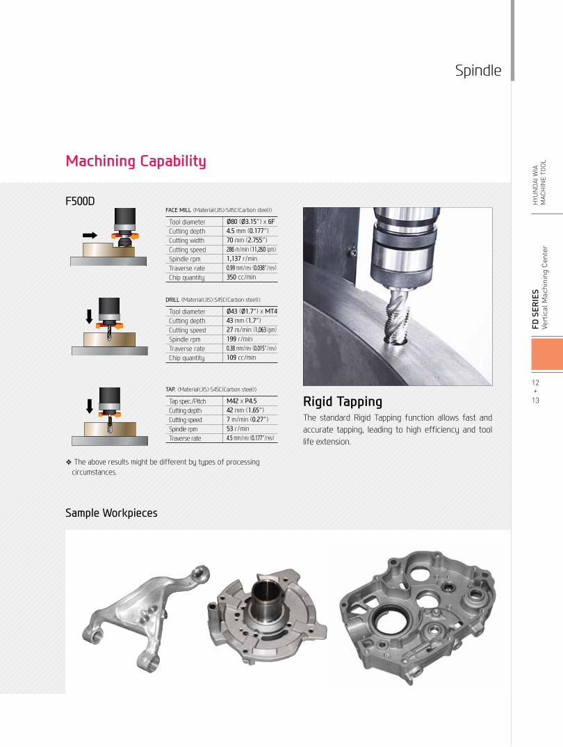
❖ The above results might be different by types of processing circumstances.
F500DFACE MILL 〈Material〈JIS〉:S45C(Carbon steel)〉
Tool diameterCutting depthCutting widthCutting speedSpindle rpmTraverse rateChip quantity
Ø80 (Ø3.15″) x 6F4.5 mm (0.177″)70 mm (2.755″)286 m/min (11,260 ipm)1,137 r/min0.99 mm/rev (0.038″/rev)350 cc/min
DRILL 〈Material〈JIS〉:S45C(Carbon steel)〉
Tool diameterCutting depthCutting speedSpindle rpmTraverse rateChip quantity
Ø43 (Ø1.7″) x MT443 mm (1.7″)27 m/min (1,063 ipm)199 r/min0.38 mm/rev (0.015″/rev)109 cc/min
TAP. 〈Material〈JIS〉:S45C(Carbon steel)〉
Tap spec./PitchCutting depthCutting speedSpindle rpmTraverse rate
M42 x P4.542 mm (1.65″)7 m/min (0.27″)53 r/min4.5 mm/rev (0.177″/rev)
Rigid TappingThe standard Rigid Tapping function allows fast and accurate tapping, leading to high efficiency and tool life extension.
Machining Capability

05 ATC & MagazineHigh Productivity withHigh Rigidity and Accurate MachiningFD Series
24 Tool Magazine 30 Tool Magazine

14+
15
FD
Ser
ieS
Vert
ical
Mac
hini
ng C
ente
rH
YUN
DAI
WIA
MAC
HIN
E TO
OL
Peripheral Device
MagazineThe tool magazine holds 24 tools as standard and 30 tools as an option.Due to the wider selection of tools and the random tool selection method, tool change time has been improved.
◉ No. of Tools : 24 EA
◉ Tool Shank : BT40◉ Max. Tool Dia. (W.T/W.O)
Ø90/Ø150 (Ø3.5″/Ø5.9″)
◉ Max. Tool Weight : 8 kg (17.6 lb)
◉ Tool Selection Method : Random
◉ No. of Tools : 24 [30] EA
◉ Tool Shank : BT40◉ Max. Tool Dia. (W.T/W.O)
Ø90/Ø150 (Ø3.5″/Ø5.9″)
◉ Max. Tool Weight : 8 kg (17.6 lb)
◉ Tool Selection Method : Random
F410D
F500D/600D
Servo ATCAdopting the Twin Arm Servo ATC further enhances position control and shortens tool change time, maximizing productivity.
Tool to Tool Time
13% Reduce
Chip to Chip Time
26% Reduce
F600D standard.

06 Smart SystemSoftware for smart operating and machiningFD Series
HW-AFCHYUNDAIWIAAdaptiveFeedControl
Software that controls the feed automatically to maintain a certain working load to extend tool life as well as productivity.
(FANUC)HW-MCSHYUNDAIWIAMachiningConditionSelection
Software that automatically sets cutting and feeding parameters according to the machining types (speed, degree, quality)
Mold-related Software
(FANUC)
Intelligent Machining
Machine Monitoring
High Precision
High Productivity Energy Savin
g
HW-TM | HW-MCS | HW-A
FC
HW-TOM HW-ESS
User Friendly
HW-MMSHW-TDC | HW
-WARM
UP
HYUNDAI WIA Smart System for Vertical Machining Center
User Convenience
HW-eDNC
HW-MCG
Faster processing and enhanced accuracy in are possiblethrough the HYUNDAI WIA Smart System. The user friendly software and equipment monitoring of the Smart System maximizes productivity.

HW-TDCHYUNDAIWIAThermalDisplacementCompensation
Software that measures the changes in the external environment as well as heat emission during processing to help reduce thermal displacement.
HW-ESSHYUNDAIWIAEnergySavingSystem
An environmental friendly software that reduces the unnecessarily wasted standby power waiting for an operation.
HW-MCGHYUNDAIWIAMachineGuidance
Software that offers operation, maintenance, management monitoring and various user friendly features.
HW-WARMUPHYUNDAIWIAWARMingUp
Warm-up software that measures main spindle halt and offers system warm-up time automatically.
HW-TOMHYUNDAIWIAToolOffsetMeasurement
User friendly GUI software that indicates tool length, diameter, and damage (H/Wexcluded)
HW-MMS
RemoteSystem
Smart Factory HW-MMS (HYUNDAI WIA-Machine Monitoring System)
A brand new manufacturing machine by HYUNDAI WIA, HW-MMS is a unique software capable of monitoring the operation status of manufacturing machines in factories, a smart solution to improve manufacturing conditions of customers.
01 05
04
03
Real-timemonitoringofmachineoperationstatus(Cloud)
Historyandstatisticsofmachineoperation(Cloud)
Historyandstatisticsofalarmoccurrence(Cloud)
Historyandstatisticsofworkcount(Cloud)
Remotediagnosis(Remote)
01
05
04
03
02
02
HW-TMHYUNDAIWIAToolMonitoring
A tool monitoring software which analyzes the load of the spindle motor to determine and monitor possible damage of tools.
(FANUC)
(FANUC) (FANUC)
16+
17
FD
Ser
ieS
Vert
ical
Mac
hini
ng C
ente
rH
YUN
DAI
WIA
MAC
HIN
E TO
OL
HYUNDAI WIA Smart System

07 SIEMENS ControllerSoftware for smart operating and machining
FD Series
DIFFERENTIATED CAPABILITIES, INTEGRATED ENGINEERING PERFECTLY INTERLINKEDSIEMENS 828D is a latest model CNC. It is designed for horizontal/vertical all-purpose equipment.
Its 80-bit control reduces processing time and increases productivity. The 828D is easy to maintain and run, with its easy setup functions.

18+
19
FD
Ser
ieS
Vert
ical
Mac
hini
ng C
ente
rH
YUN
DAI
WIA
MAC
HIN
E TO
OL
• Dialogue-type programming, simple and convenient
• Effective specifications for small quantity batch production
• Step-by-step operation possible without knowledge of the DIN/ISO code
Shop Mill
• 3D confirmation of the completed processing configuration of the NC program is possible.
•Offers standards for 2D simulation.• Possible to confirm the simulation of the
NC grogram during processing.
3D Simulation
• Easy to install/uninstall an option (Ex : barfeeder and chip conveyor, etc.)
• Possible to install in one motion without revision of individual perimeters.
• A spate list is unnecessary as option items are indicated with letters.
Easy Extend
Easy input/output of a program is possible as a USB memory card, a CF memory card and LAN can all be used.
Variable Communication Port
RJ 45 Ethernet
USB 2.0
Compact Flash Card
If the ISO Dialect (G291) is ordered, JIS-based G-code programs can be used. (Standard)
SIEMENS Technology SIEMENS Communication
ISO CodeProgramming
SIEMENS 828D comes with Advanced Surface, metal processing software that monitors speed and accuracy.
SIEMENS
SIEMENS Advanced Surface
Speed
Speed
SINUMERIK + SINAMICS 80bit NANO FP Accuracy
Machining Time Time : 48 min
Unblanced Velocity
Machining Time Time : 33 min
Blanced Velocity

User ConvenienceVarious Devices for User Convenience
Measuring Device
08FD Series
Hydraulic Supply UnitInstead of the standard hydraulic supply unit, an optional fixture unit can bring the pressure up to 70 bar (1,015 psi), maximizing the clamping force on the fixture.
Hydraulic Device
U-CenterWith U-Center, both external and internal diameter turning become possible, allowing for a wide range of variety in products.
Precision Device
NC Rotary TableThe NCRT makes it possible to machine up to 5-axis. Various types of products can be machined.
❖ Please check interference when mounting NCRT .
Touch SensorWorkpiece coordinate values can be set automatically using the optional spindle probe.
TLM - Laser & TouchTool lengths and diameters can be set automatically using the optional tool setter. This can also be used to monitor tool attrition and detect broken tools.
Laser Type
Touch Type

Optional
20+
21
FD
Ser
ieS
Vert
ical
Mac
hini
ng C
ente
rH
YUN
DAI
WIA
MAC
HIN
E TO
OL
Oil SkimmerAn oil skimmer can increase coolant and tool life by removing tramp oil contaminants.
Mist CollectorMist Collector reduces the amount of smoke and oil mist in the air. This helps build a safe and comfortable working environment and improve durability.
Environment Device
Std. Coolant (Nozzle)
Bed Flushing Coolant
Through Spindle Coolant
(20/30 bar [290/435 psi])
Shower Coolant
Gun Coolant
Side Oil Hole Coolant
Standard
Standard
Option
Option
Option
Option
Coolant Unit
•Hinge Belt Type : Highly efficient when disposing a lot of chips. Capable of handling stringy chips. (Long Chip)
•Scraper Type : Convenient for shortly cut chips.. (Short Chip)•Drum Filter Type : Advantageous in precision, as the chips do not flow in to the coolant nozzle.
(AL Chip)
Timely and effective disposal of chips will enhance productivity as well as the working environment.
Chip Conveyor

Spindle F410D
10,000rpm(15/11kW [20/14.5HP]) FANUC ●
10,000rpm(22.5kW [30.2HP]) SIEMENS ○
Spindle Cooling System ○ATC
ATC Extension24 ●30 -
Tool Shank TypeBT40 ●CAT40 ○
U-Center D'andrea ☆
Pull Stud
45° ☆60° ☆75° ●90° ☆
Table & ColumnAPC Rotary Turn ●TAP TYPE Pallet ●T-SLOT Pallet ○NC Rotary Table ☆High Column -Coolant SystemStd. Coolant (Nozzle) ●Bed Flushing Coolant ●
Through spindle coolant*
20bar (290 psi) ○
30bar (435 psi),20ℓ(5.3 gal) ○
70bar (1,015 psi), 15ℓ(4 gal) ○
70bar (1,015 psi), 30ℓ(8 gal) -
Top Cover ○Shower Coolant ☆Gun Coolant ○Side Oil Hole Coolant ☆Air Gun ○Cutting Air Blow ○Tool Measuring Air Blow (Only for TLM) ○Air Blow for Automation ☆Thru MQL Device (Without MQL) ☆Coolant Chiller ☆Power Coolant System (For Automation) ☆Chip Disposal
Coolant Tank300ℓ(79.3 gal) ●600ℓ(158.5 gal) -
Cabin Screw Chip Conveyor -
Chip Conveyor(Hinge/Scraper)
Rear (Left) ○Front (Right) -Right (Rear) -
Special Chip Conveyor (Drum Filter) ☆
Chip Wagon
Standard(180ℓ[47.5 gal]) ○
Swing(200ℓ[52.8 gal]) ○
Large Swing(290ℓ[76.6 gal]) ○
Large Size(330ℓ[87.2 gal]) ○
Customized ☆Safety DeviceTotal Splash Guard ●S/WMachine guidance (HW-MCG) : FANUC/SIEMENS ☆/-Tool Monitoring (HW-TM) ○DNC Software (HW-eDNC) ○Spindle Heat Distortion Compensation (HW-TDC) ○Spindle Warm up Function (HW-WARMUP) : FANUC/SIEMENS ☆/-Energy Saving System (HW-ESS) : FANUC/SIEMENS ☆/-Machine Monitoring System (HW-MMS) ○Tool Offset Measurement (HW-TOM) ☆
S/W F410D
Machining Condition Selection (HW-MCS) : FANUC/SIEMENS ☆/-Adaptive Feed Control (HW-AFC) : FANUC/SIEMENS ☆/-Conversational Program (HW-DPRO) ○Electric DeviceCall Light 1 Color : ■ ●Call Light 2 Color : ■■ ○Call Light 3 Color : ■■■ ○Call Light & Buzzer 3 Color : ■■■B ○Work Light ●Electric Cabinet Light ○Remote MPG ●
3 Axis MPGFANUC ○SIEMENS -
Work Counter Digital ○Total Counter Digital ○Tool Counter Digital ○
Multi Tool Counter6 EA ○9 EA ○
Electric Circuit Breaker ○AVR (Auto Voltage Regulator) ☆Transformer 25kVA ○Auto Power Off ○Back up Module for Black out ○Measuring Device
Air ZeroTACO ○SMC ○
Work Measuring Device ○
TLM(Marposs/Renishaw/Blum)
Touch ○Laser ☆
Tool Broken Detective Device ☆Linear Scale X/Y/Z Axis -
Coolant Level Sensor (Only for Chip Conveyor, Bladder Type) ☆
EnviornmentAir Conditioner ○Dehumidifier ○Oil Mist Collector ○Oil Skimmer (Only for Chip Conveyor) ○MQL (Minimal Quantity Lubrication) ☆Fixture & Automation
Auto DoorStd. ○High Speed ☆
Auto Shutter (Only for Automatic System) -Sub O/P ☆
NC Rotary TableI/FSingle ○Channel ☆
Control of Additional Axis1Axis ☆2Axis -
External M Code 4ea ○Automation Interface ☆
I/O Extension (In & Out)16 Contact ○32 Contact ○
Hyd. Device
Std. Hyd. Unit
65bar (942.7 psi) / 35ℓ(9.2 gal) ●
45bar (652.7 psi) / 60ℓ(15.8 gal) -
45bar (652.7 psi) / 13ℓ(3.4 gal) -
Center Hyd. Supply Device 2x3 (6 Port) ○2x5 (10 Port) ○
Compact Center Hyd. Supply Device 2x3 (6 Port) -
Fixture Hyd. Unit70bar (1,015 psi) ○100bar (1,450 psi) ○Customized ☆
ETCTool Box ●Customized Color Need for Munsel No. ☆CAD&CAM Software ☆
Standard & Optional ● : Standard ○ : Option ☆ : Prior Consultation - : Non Applicable
Through Spindle Coolant* : Please check the filter types with sales representative.Specifications are subject to change without notice for improvement.
SPECIFICATIONS

22+
23
FD
Ser
ieS
Vert
ical
Mac
hini
ng C
ente
rH
YUN
DAI
WIA
MAC
HIN
E TO
OL
SPECIFICATIONS
Spindle F500D F600D
8,000rpm(15/11kW [20/15HP) BELT ● ●
8,000rpm(43/18.5kW [58/25HP]) BELT (SIEMENS) ○ -
10,000rpm(15/11kW [20/15HP) BELT ○ -
12,000rpm(11/7.5kW [15/10HP) DIRECT ○ ○
Spindle Cooling System8,000rpm ○ ○10,000rpm ● -12,000rpm ● ●
ATC
ATC Extension24 ● ●30 ○ ○
Tool Shank TypeBT40 ● ●CAT40 ○ ○
U-Center D'andrea ☆ ☆
Pull Stud
45° ● ●60° ☆ ☆75° ☆ ☆90° ☆ ☆
Table & ColumnAPC Rotary Turn ● ●TAP TYPE Pallet ● ●T-SLOT Pallet ○ -NC Rotary Table ☆ ☆High Column - -Coolant SystemStd. Coolant (Nozzle) ● ●Bed Flushing Coolant ○ ○
Through spindle coolant*
20bar (290 psi) ○ ○30bar (435 psi),20ℓ(5.3 gal) ○ ○
70bar (1,015 psi), 15ℓ(4 gal) ○ ○
70bar (1,015 psi), 30ℓ(8 gal) - -
Top Cover ○ ○Shower Coolant ☆ ☆Gun Coolant ○ ○Side Oil Hole Coolant ☆ ☆Air Gun ○ ○Cutting Air Blow ○ ○Tool Measuring Air Blow (Only for TLM) ○ ○Air Blow for Automation ☆ ☆Thru MQL Device (Without MQL) ☆ ☆Coolant Chiller ☆ ☆Power Coolant System (For Automation) ☆ ☆Chip Disposal
Coolant Tank300ℓ(79.3 gal) ● -460ℓ(121.5 gal) ○ -600ℓ(158.5 gal) - ●
Cabin Screw Chip Conveyor - -
Chip Conveyor(Hinge/Scraper)
Rear (Rear) ○ -Rear (Right) ○ ○Right (Rear) - -
Special Chip Conveyor (Drum Filter) ☆ ☆
Chip Wagon
Standard (180ℓ[47.5 gal]) ○ ○Swing (200ℓ[52.8 gal]) ○ ○Large Swing (290ℓ[76.6 gal]) ○ ○Large Size (330ℓ[87.2 gal]) ○ ○Customized ☆ ☆
Safety DeviceTotal Splash Guard ● ●S/WMachine guidance (HW-MCG) : FANUC/SIEMENS ☆/- ☆Tool Monitoring (HW-TM) ○ ○DNC Software (HW-eDNC) ○ ○Spindle Heat Distortion Compensation (HW-TDC) ○ ○Spindle Warm up Function (HW-WARMUP) : FANUC/SIEMENS ☆/- ☆Energy Saving System (HW-ESS) : FANUC/SIEMENS ☆/- ☆Machine Monitoring System (HW-MMS) ○ ○
S/W F500D F600DTool Offset Measurement (HW-TOM) ☆ ☆Machining Condition Selection (HW-MCS) : FANUC/SIEMENS ☆/- ☆Adaptive Feed Control (HW-AFC) : FANUC/SIEMENS ☆/- ☆Conversational Program (HW-DPRO) ○ ○Electric DeviceCall Light 1 Color : ■ ● ●Call Light 2 Color : ■■ ○ ○Call Light 3 Color : ■■■ ○ ○Call Light & Buzzer 3 Color : ■■■B ● ●Work Light ○ ○Electric Cabinet Light ● ●Remote MPG ○ ○
3 Axis MPGFANUC - -SIEMENS ○ ○
Work Counter Digital ○ ○Total Counter Digital ○ ○Tool Counter Digital ○ ○
Multi Tool Counter6 EA ○ ○9 EA ○ ○
Electric Circuit Breaker ☆ ☆AVR (Auto Voltage Regulator) ☆
Transformer25kVA - -35kVA ○ ○
Auto Power Off ○ ○Back up Module for Black out ○ ○Measuring Device
Air ZeroTACO ○ ○SMC ○ ○
Work Measuring Device ○ ○TLM(Marposs/Renishaw/Blum)
Touch ○ ○Laser ☆ ☆
Tool Broken Detective Device ☆ ☆Linear Scale X/Y/Z Axis ○ ○Coolant Level Sensor (Only for Chip Conveyor, Bladder Type) ☆ ☆
EnviornmentAir Conditioner ○ ○Dehumidifier ○ ○Oil Mist Collector ○ ○Oil Skimmer (Only for Chip Conveyor) ○ ○MQL (Minimal Quantity Lubrication) ☆ ☆Fixture & Automation
Auto DoorStd. ○ ○High Speed ☆ ☆
Auto Shutter (Only for Automatic System) - -Sub O/P ☆ ☆
NC Rotary TableI/FSingle ○ ○Channel ☆ ☆
Control of Additional Axis1Axis ☆ ☆2Axis - -
External M Code 4ea ○ ○Automation Interface ☆ ☆
I/O Extension (In & Out)16 Contact ○ ○32 Contact ○ ○
Hyd. Device
Std. Hyd. Unit
65bar (942.7 psi) / 35ℓ(9.2 gal) - -
45bar (652.7 psi) / 60ℓ(15.8 gal) ● -
45bar (652.7 psi) / 13ℓ(3.4 gal) - ●
Center Hyd. Supply Device 2x3 (6 Port) ○ ○2x5 (10 Port) ○ ○
Compact Center Hyd. Supply Device 2x3 (6 Port) ○ -
Fixture Hyd. Unit70bar (1,015 psi) ○ ○100bar (1,450 psi) - -Customized ☆ ☆
ETCTool Box ● ●Customized Color Need for Munsel No. ☆ ☆CAD&CAM Software ☆ ☆
Standard & Optional ● : Standard ○ : Option ☆ : Prior Consultation - : Non Applicable
Through Spindle Coolant* : Please check the filter types with sales representative.Specifications are subject to change without notice for improvement.

unit : mm(in)External Dimensions
F410D
SPECIFICATIONS
X-STROKE570(22.4) Y-STORKE
410 (16.1)
Z-S
TRO
KE
580
(22.
8)
DOOR OPEN650(25.6)
601.6 (23.7) 2210 (87)
1200
(47.
2)
2337
(88)
630
(24.
8)42
0 (1
6.5)
1080
(42.
5)50
0 (1
9.7)
729.2 (28.7)3210 (126.4)
2130
(83.
9)
1290
(50.
8)11
90 (4
6.9)
2480
(97.
6)
957
(37.
7)
X-STROKE570(22.4) Y-STORKE
410 (16.1)
Z-S
TRO
KE
580
(22.
8)
DOOR OPEN650(25.6)
601.6 (23.7) 2210 (87)
1200
(47.
2)
2337
(88)
630
(24.
8)42
0 (1
6.5)
1080
(42.
5)50
0 (1
9.7)
729.2 (28.7)3210 (126.4)
2130
(83.
9)
1290
(50.
8)11
90 (4
6.9)
2480
(97.
6)
957
(37.
7)

unit : mm(in)External Dimensions
24+
25
FD
Ser
ieS
Vert
ical
Mac
hini
ng C
ente
rH
YUN
DAI
WIA
MAC
HIN
E TO
OL
SPECIFICATIONS
F500D
RearChip Conveyor
Right SideChip Conveyor600(23.6)
795(31.3)
460(18.1)
570(
22.4
)
935(
36.8
)Rear
Chip Conveyor
Right SideChip Conveyor600(23.6)
795(31.3)
460(18.1)
570(
22.4
)
935(
36.8
)

unit : mm(in)External Dimensions
SPECIFICATIONS
Right SideChip Conveyor
800(31.5)
600(23.6)
600(
23.6
)20
0(7
.9)
Right SideChip Conveyor
800(31.5)
600(23.6)
600(
23.6
)20
0(7
.9)
F600D

unit : mm(in)Table Dimensions
F410D
26+
27
FD
Ser
ieS
Vert
ical
Mac
hini
ng C
ente
rH
YUN
DAI
WIA
MAC
HIN
E TO
OL
SPECIFICATIONS
Tap Detail(M16 Tap)
Tap Detail(M16 Tap)
Tap Detail(M16 Tap)
T-Slot Detail
T-Slot Detail
15 (0.6
)15 (0.6
)
15 (0.6
)15 (0.6
)
100
(3.9
)10
0(3
.9)
100
(3.9
)25 (1
)25 (1
)
450
(17.
7)
100
(3.9
)
100(3.9)
60(2.4)
340 (13.4) 340 (13.4) 60(2.4)
30(1.2)
100
(3.9
)10
0(3
.9)
450
(17.
7)
55(2.2)
55(2.2)
1818H12
550
(21.
6)(S
ELF
CU
TTIN
G S
TRO
KE
)
20(0.8)
17 (SELF CUTT'G BEFORE)
1818H12
18 (SELF CUTT'G AFTER)
650
(25.
6)
150 (5.9)150 (5.9)145(5.7)
145(5.7)
150 (5.9)150 (5.9)
1000 (39.3)
8-M6 TA
P DP20
8-M6 TAP DP20
55(2.2)
55(2.2)
340 (13.4)20
0 (7
.8)
110
(4.3
)11
0 (4
.3)
200
(7.8
)
200(
7.8)
110(
4.3)
110(
4.3)
200(
7.8)
100(3.9)
145(5.7)
100(3.9)
100(3.9)
100(3.9)
55(2.2)
55(2.2)
100(3.9)
100(3.9)
145(5.7)
100(3.9)
60(2.4)
340 (13.4) 340 (13.4) 60(2.4)
100(3.9)
100(3.9)
1000 (39.3)
100
(3.9
)10
0(3
.9)
100
(3.9
)10
0(3
.9)
650
(25.
6)
STD. MM TAP (M16 TAP)OPT. INCH TAP (5/8"-11 UNC-2B)
18H8 +0.027 0
32 (1
.3)
30(1.2)
+2.00
C0.
6 0.5
12 (0.5
)+2
.0 0
45°
1(0.04)
8-Ø
6.7D
R. D
P21
M8
TAP
DP
15
100
(3.9
)10
0(3
.9)
100(3.9)
1200 (47.2)
128
(5)
128
(5)
65(2.5)
27°
400
(15.
7)50 (2
)50 (2
)
500 (19.7)
75(2.9)
500 (19.7)200 (7.8)
±0.2 125(4.9)
25(1)
25(1)
±1.0
700
(27.
5)±1
.0
100(3.9)
±0.2100(3.9)
±0.2
444
(17.
5)
16H8 +0.027 0
26 (1
)
27(1.1)
+2.00
16 (0.6)
C0.
6 0.5
10.5
(0.4
)
+2.0 0
25S
45°1(0.04)
T-Slot Detail
18H8 +0.027 0
32 (1
.3)
30(1.2)
+2.00
C0.
6 0.5
12 (0.5
)+2
.0 0
45°
1(0.04)
17(0.7)
55 (2.2
)55 (2.2
)79
0 (3
1.1)
(SE
LF C
UTT
ING
STR
OK
E)
100(3.9)
100x4=400(15.7)100x4=400(15.7)
100(3.9)
125(4.9)
125(4.9)
125(4.9)
125(4.9)
P.C.D 200(7.9)
900
(35.
4)
60(2.3)
200(7.8)
1380 (54.3)60(2.3)
110
(4.3
)68
0 (2
6.7)
110
(4.3
)
25(1)
25(1)
50 (1)
330
(13)
70 (2.7
)70 (2.7
)33
0 (1
3)50 (1
)
120°
Ø20(Ø0.8)
1(0
.04)
35 (1
.4)
40 (1
.6)
118°
Ø20(Ø0.8)
18(0.7)
7(0
.3)
1 (0
.04)
35 (1
.4)
40 (1
.6)
32 (1
.3)
20 (0.8
)12 (0.5
)
30 (1.2)
CenterOther
600
(23.
6)50 (2
)50 (2
)
50(2)
50(2)
200(7.8)
1200 (47.2)
100(3.9)
100(3.9)
100(3.9)
100(3.9)
50(2)
50(2)
100(3.9)
100(3.9)
100(3.9)
100(3.9)
50 (2)
50 (2)
100
(3.9
)10
0(3
.9)
100
(3.9
)
700
(27.
5)100
(3.9
)10
0(3
.9)
100
(3.9
)
70(2.7)60
(2.4)590 (23.2) 60
(2.4)590 (23.2)100
(3.9)100(3.9)
1500 (59)
125(4.9)
125(4.9)
125(4.9)
125
(4.9
)12
5(4
.9)
125
(4.9
)12
5(4
.9)
125
(4.9
)12
5(4
.9)
75 (3) 110
(4.3
)68
0 (2
6.7)
900
(35.
4)
110
(4.3
)
80(3.1)
125(4.9)
70(2.7)
125(4.9)
125(4.9)
125(4.9)
80(3.1)
125(4.9)
Tap Detail(M16 Tap)
120°
Ø20(Ø0.8)
1(0
.04)
35 (1
.4)
40 (1
.6)
T-Slot Detail
55 (2.2
)59
0 (2
3.2)
-SE
LF C
UTT
ING
STR
OK
E
55 (2.2
)59
0 (2
3.2)
-SEL
F C
UTT
ING
STR
OKE
55 (2.2
)
50 (1.9
)20
0 (7
.9)
100
(3.9
)10
0(3
.9)
200
(7.9
)50 (1.9
)
125 (4.9) 100X3=300(3.9X3=11.7)
100 (3.9)75 (3)75 (3)
100 (3.9)100X3=300
(3.9X3=11.7)125 (4.9)
128
(5)
128
(5)
444
(17.
5)
700
(27.
5)
200 (7.9)25 (1)25 (1)
65(2.6)
1070 (42)65(2.6)
23° 23°
45° 45° 45°
45°
P.C.Dø200 (7.9)
18.000017
R4.00008-M8 TAP DP20
Tap Detail(M16 Tap)
Tap Detail(M16 Tap)
Tap Detail(M16 Tap)
T-Slot Detail
T-Slot Detail
15 (0.6
)15 (0.6
)
15 (0.6
)15 (0.6
)
100
(3.9
)10
0(3
.9)
100
(3.9
)25 (1
)25 (1
)
450
(17.
7)
100
(3.9
)
100(3.9)
60(2.4)
340 (13.4) 340 (13.4) 60(2.4)
30(1.2)
100
(3.9
)10
0(3
.9)
450
(17.
7)
55(2.2)
55(2.2)
1818H12
550
(21.
6)(S
ELF
CU
TTIN
G S
TRO
KE
)
20(0.8)
17 (SELF CUTT'G BEFORE)
1818H12
18 (SELF CUTT'G AFTER)
650
(25.
6)
150 (5.9)150 (5.9)145(5.7)
145(5.7)
150 (5.9)150 (5.9)
1000 (39.3)
8-M6 TA
P DP20
8-M6 TAP DP20
55(2.2)
55(2.2)
340 (13.4)
200
(7.8
)11
0 (4
.3)
110
(4.3
)20
0 (7
.8)
200(
7.8)
110(
4.3)
110(
4.3)
200(
7.8)
100(3.9)
145(5.7)
100(3.9)
100(3.9)
100(3.9)
55(2.2)
55(2.2)
100(3.9)
100(3.9)
145(5.7)
100(3.9)
60(2.4)
340 (13.4) 340 (13.4) 60(2.4)
100(3.9)
100(3.9)
1000 (39.3)
100
(3.9
)10
0(3
.9)
100
(3.9
)10
0(3
.9)
650
(25.
6)
STD. MM TAP (M16 TAP)OPT. INCH TAP (5/8"-11 UNC-2B)
18H8 +0.027 0
32 (1
.3)
30(1.2)
+2.00
C0.
6 0.5
12 (0.5
)+2
.0 0
45°
1(0.04)
8-Ø
6.7D
R. D
P21
M8
TAP
DP
15
100
(3.9
)10
0(3
.9)
100(3.9)
1200 (47.2)
128
(5)
128
(5)
65(2.5)
27°
400
(15.
7)50 (2
)50 (2
)
500 (19.7)
75(2.9)
500 (19.7)200 (7.8)
±0.2 125(4.9)
25(1)
25(1)
±1.0
700
(27.
5)±1
.0
100(3.9)
±0.2100(3.9)
±0.2
444
(17.
5)
16H8 +0.027 0
26 (1
)
27(1.1)
+2.00
16 (0.6)
C0.
6 0.5
10.5
(0.4
)
+2.0 0
25S
45°1(0.04)
T-Slot Detail
18H8 +0.027 0
32 (1
.3)
30(1.2)
+2.00
C0.
6 0.5
12 (0.5
)+2
.0 0
45°
1(0.04)
17(0.7)
55 (2.2
)55 (2.2
)79
0 (3
1.1)
(SE
LF C
UTT
ING
STR
OK
E)
100(3.9)
100x4=400(15.7)100x4=400(15.7)
100(3.9)
125(4.9)
125(4.9)
125(4.9)
125(4.9)
P.C.D 200(7.9)
900
(35.
4)
60(2.3)
200(7.8)
1380 (54.3)60(2.3)
110
(4.3
)68
0 (2
6.7)
110
(4.3
)
25(1)
25(1)
50 (1)
330
(13)
70 (2.7
)70 (2.7
)33
0 (1
3)50 (1
)
120°
Ø20(Ø0.8)
1(0
.04)
35 (1
.4)
40 (1
.6)
118°
Ø20(Ø0.8)
18(0.7)
7(0
.3)
1 (0
.04)
35 (1
.4)
40 (1
.6)
32 (1
.3)
20 (0.8
)12 (0.5
)
30 (1.2)
CenterOther
600
(23.
6)50 (2
)50 (2
)
50(2)
50(2)
200(7.8)
1200 (47.2)
100(3.9)
100(3.9)
100(3.9)
100(3.9)
50(2)
50(2)
100(3.9)
100(3.9)
100(3.9)
100(3.9)
50 (2)
50 (2)
100
(3.9
)10
0(3
.9)
100
(3.9
)
700
(27.
5)100
(3.9
)10
0(3
.9)
100
(3.9
)
70(2.7)60
(2.4)590 (23.2) 60
(2.4)590 (23.2)100
(3.9)100(3.9)
1500 (59)
125(4.9)
125(4.9)
125(4.9)
125
(4.9
)12
5(4
.9)
125
(4.9
)12
5(4
.9)
125
(4.9
)12
5(4
.9)
75 (3) 110
(4.3
)68
0 (2
6.7)
900
(35.
4)
110
(4.3
)
80(3.1)
125(4.9)
70(2.7)
125(4.9)
125(4.9)
125(4.9)
80(3.1)
125(4.9)
Tap Detail(M16 Tap)
120°
Ø20(Ø0.8)
1(0
.04)
35 (1
.4)
40 (1
.6)
T-Slot Detail
55 (2.2
)59
0 (2
3.2)
-SE
LF C
UTT
ING
STR
OK
E
55 (2.2
)59
0 (2
3.2)
-SEL
F C
UTT
ING
STR
OKE
55 (2.2
)
50 (1.9
)20
0 (7
.9)
100
(3.9
)10
0(3
.9)
200
(7.9
)50 (1.9
)
125 (4.9) 100X3=300(3.9X3=11.7)
100 (3.9)75 (3)75 (3)
100 (3.9)100X3=300
(3.9X3=11.7)125 (4.9)
128
(5)
128
(5)
444
(17.
5)
700
(27.
5)
200 (7.9)25 (1)25 (1)
65(2.6)
1070 (42)65(2.6)
23° 23°
45° 45° 45°
45°
P.C.Dø200 (7.9)
18.000017
R4.00008-M8 TAP DP20
unit : mm(in)Table Dimensions
F500D
Tap Detail(M16 Tap)
Tap Detail(M16 Tap)
Tap Detail(M16 Tap)
T-Slot Detail
T-Slot Detail
15 (0.6
)15 (0.6
)
15 (0.6
)15 (0.6
)
100
(3.9
)10
0(3
.9)
100
(3.9
)25 (1
)25 (1
)
450
(17.
7)
100
(3.9
)
100(3.9)
60(2.4)
340 (13.4) 340 (13.4) 60(2.4)
30(1.2)
100
(3.9
)10
0(3
.9)
450
(17.
7)
55(2.2)
55(2.2)
1818H12
550
(21.
6)(S
ELF
CU
TTIN
G S
TRO
KE
)
20(0.8)
17 (SELF CUTT'G BEFORE)
1818H12
18 (SELF CUTT'G AFTER)
650
(25.
6)
150 (5.9)150 (5.9)145(5.7)
145(5.7)
150 (5.9)150 (5.9)
1000 (39.3)
8-M6 TA
P DP20
8-M6 TAP DP20
55(2.2)
55(2.2)
340 (13.4)
200
(7.8
)11
0 (4
.3)
110
(4.3
)20
0 (7
.8)
200(
7.8)
110(
4.3)
110(
4.3)
200(
7.8)
100(3.9)
145(5.7)
100(3.9)
100(3.9)
100(3.9)
55(2.2)
55(2.2)
100(3.9)
100(3.9)
145(5.7)
100(3.9)
60(2.4)
340 (13.4) 340 (13.4) 60(2.4)
100(3.9)
100(3.9)
1000 (39.3)
100
(3.9
)10
0(3
.9)
100
(3.9
)10
0(3
.9)
650
(25.
6)
STD. MM TAP (M16 TAP)OPT. INCH TAP (5/8"-11 UNC-2B)
18H8 +0.027 0
32 (1
.3)
30(1.2)
+2.00
C0.
6 0.5
12 (0.5
)+2
.0 0
45°
1(0.04)
8-Ø
6.7D
R. D
P21
M8
TAP
DP
15
100
(3.9
)10
0(3
.9)
100(3.9)
1200 (47.2)
128
(5)
128
(5)
65(2.5)
27°
400
(15.
7)50 (2
)50 (2
)
500 (19.7)
75(2.9)
500 (19.7)200 (7.8)
±0.2 125(4.9)
25(1)
25(1)
±1.0
700
(27.
5)±1
.0
100(3.9)
±0.2100(3.9)
±0.2
444
(17.
5)
16H8 +0.027 0
26 (1
)
27(1.1)
+2.00
16 (0.6)
C0.
6 0.5
10.5
(0.4
)
+2.0 0
25S
45°1(0.04)
T-Slot Detail
18H8 +0.027 0
32 (1
.3)
30(1.2)
+2.00
C0.
6 0.5
12 (0.5
)+2
.0 0
45°
1(0.04)
17(0.7)
55 (2.2
)55 (2.2
)79
0 (3
1.1)
(SE
LF C
UTT
ING
STR
OK
E)
100(3.9)
100x4=400(15.7)100x4=400(15.7)
100(3.9)
125(4.9)
125(4.9)
125(4.9)
125(4.9)
P.C.D 200(7.9)
900
(35.
4)
60(2.3)
200(7.8)
1380 (54.3)60(2.3)
110
(4.3
)68
0 (2
6.7)
110
(4.3
)
25(1)
25(1)
50 (1)
330
(13)
70 (2.7
)70 (2.7
)33
0 (1
3)50 (1
)
120°
Ø20(Ø0.8)
1(0
.04)
35 (1
.4)
40 (1
.6)
118°
Ø20(Ø0.8)
18(0.7)
7(0
.3)
1 (0
.04)
35 (1
.4)
40 (1
.6)
32 (1
.3)
20 (0.8
)12 (0.5
)
30 (1.2)
CenterOther
600
(23.
6)50 (2
)50 (2
)
50(2)
50(2)
200(7.8)
1200 (47.2)
100(3.9)
100(3.9)
100(3.9)
100(3.9)
50(2)
50(2)
100(3.9)
100(3.9)
100(3.9)
100(3.9)
50 (2)
50 (2)
100
(3.9
)10
0(3
.9)
100
(3.9
)
700
(27.
5)100
(3.9
)10
0(3
.9)
100
(3.9
)
70(2.7)60
(2.4)590 (23.2) 60
(2.4)590 (23.2)100
(3.9)100(3.9)
1500 (59)
125(4.9)
125(4.9)
125(4.9)
125
(4.9
)12
5(4
.9)
125
(4.9
)12
5(4
.9)
125
(4.9
)12
5(4
.9)
75 (3) 110
(4.3
)68
0 (2
6.7)
900
(35.
4)
110
(4.3
)
80(3.1)
125(4.9)
70(2.7)
125(4.9)
125(4.9)
125(4.9)
80(3.1)
125(4.9)
Tap Detail(M16 Tap)
120°
Ø20(Ø0.8)
1(0
.04)
35 (1
.4)
40 (1
.6)
T-Slot Detail
55 (2.2
)59
0 (2
3.2)
-SE
LF C
UTT
ING
STR
OK
E
55 (2.2
)59
0 (2
3.2)
-SEL
F C
UTT
ING
STR
OKE
55 (2.2
)
50 (1.9
)20
0 (7
.9)
100
(3.9
)10
0(3
.9)
200
(7.9
)50 (1.9
)
125 (4.9) 100X3=300(3.9X3=11.7)
100 (3.9)75 (3)75 (3)
100 (3.9)100X3=300
(3.9X3=11.7)125 (4.9)
128
(5)
128
(5)
444
(17.
5)
700
(27.
5)
200 (7.9)25 (1)25 (1)
65(2.6)
1070 (42)65(2.6)
23° 23°
45° 45° 45°
45°
P.C.Dø200 (7.9)
18.000017
R4.00008-M8 TAP DP20
Tap Detail(M16 Tap)
Tap Detail(M16 Tap)
Tap Detail(M16 Tap)
T-Slot Detail
T-Slot Detail
15 (0.6
)15 (0.6
)
15 (0.6
)15 (0.6
)
100
(3.9
)10
0(3
.9)
100
(3.9
)25 (1
)25 (1
)
450
(17.
7)
100
(3.9
)
100(3.9)
60(2.4)
340 (13.4) 340 (13.4) 60(2.4)
30(1.2)
100
(3.9
)10
0(3
.9)
450
(17.
7)
55(2.2)
55(2.2)
1818H12
550
(21.
6)(S
ELF
CU
TTIN
G S
TRO
KE
)
20(0.8)
17 (SELF CUTT'G BEFORE)
1818H12
18 (SELF CUTT'G AFTER)
650
(25.
6)
150 (5.9)150 (5.9)145(5.7)
145(5.7)
150 (5.9)150 (5.9)
1000 (39.3)
8-M6 TA
P DP20
8-M6 TAP DP20
55(2.2)
55(2.2)
340 (13.4)
200
(7.8
)11
0 (4
.3)
110
(4.3
)20
0 (7
.8)
200(
7.8)
110(
4.3)
110(
4.3)
200(
7.8)
100(3.9)
145(5.7)
100(3.9)
100(3.9)
100(3.9)
55(2.2)
55(2.2)
100(3.9)
100(3.9)
145(5.7)
100(3.9)
60(2.4)
340 (13.4) 340 (13.4) 60(2.4)
100(3.9)
100(3.9)
1000 (39.3)
100
(3.9
)10
0(3
.9)
100
(3.9
)10
0(3
.9)
650
(25.
6)
STD. MM TAP (M16 TAP)OPT. INCH TAP (5/8"-11 UNC-2B)
18H8 +0.027 0
32 (1
.3)
30(1.2)
+2.00
C0.
6 0.5
12 (0.5
)+2
.0 0
45°
1(0.04)
8-Ø
6.7D
R. D
P21
M8
TAP
DP
15
100
(3.9
)10
0(3
.9)
100(3.9)
1200 (47.2)
128
(5)
128
(5)
65(2.5)
27°
400
(15.
7)50 (2
)50 (2
)
500 (19.7)
75(2.9)
500 (19.7)200 (7.8)
±0.2 125(4.9)
25(1)
25(1)
±1.0
700
(27.
5)±1
.0
100(3.9)
±0.2100(3.9)
±0.2
444
(17.
5)
16H8 +0.027 0
26 (1
)
27(1.1)
+2.00
16 (0.6)
C0.
6 0.5
10.5
(0.4
)
+2.0 0
25S
45°1(0.04)
T-Slot Detail
18H8 +0.027 0
32 (1
.3)
30(1.2)
+2.00
C0.
6 0.5
12 (0.5
)+2
.0 0
45°
1(0.04)
17(0.7)
55 (2.2
)55 (2.2
)79
0 (3
1.1)
(SE
LF C
UTT
ING
STR
OK
E)
100(3.9)
100x4=400(15.7)100x4=400(15.7)
100(3.9)
125(4.9)
125(4.9)
125(4.9)
125(4.9)
P.C.D 200(7.9)
900
(35.
4)
60(2.3)
200(7.8)
1380 (54.3)60(2.3)
110
(4.3
)68
0 (2
6.7)
110
(4.3
)
25(1)
25(1)
50 (1)
330
(13)
70 (2.7
)70 (2.7
)33
0 (1
3)50 (1
)
120°
Ø20(Ø0.8)
1(0
.04)
35 (1
.4)
40 (1
.6)
118°
Ø20(Ø0.8)
18(0.7)
7(0
.3)
1 (0
.04)
35 (1
.4)
40 (1
.6)
32 (1
.3)
20 (0.8
)12 (0.5
)
30 (1.2)
CenterOther
600
(23.
6)50 (2
)50 (2
)
50(2)
50(2)
200(7.8)
1200 (47.2)
100(3.9)
100(3.9)
100(3.9)
100(3.9)
50(2)
50(2)
100(3.9)
100(3.9)
100(3.9)
100(3.9)
50 (2)
50 (2)
100
(3.9
)10
0(3
.9)
100
(3.9
)
700
(27.
5)100
(3.9
)10
0(3
.9)
100
(3.9
)
70(2.7)60
(2.4)590 (23.2) 60
(2.4)590 (23.2)100
(3.9)100(3.9)
1500 (59)
125(4.9)
125(4.9)
125(4.9)
125
(4.9
)12
5(4
.9)
125
(4.9
)12
5(4
.9)
125
(4.9
)12
5(4
.9)
75 (3) 110
(4.3
)68
0 (2
6.7)
900
(35.
4)
110
(4.3
)
80(3.1)
125(4.9)
70(2.7)
125(4.9)
125(4.9)
125(4.9)
80(3.1)
125(4.9)
Tap Detail(M16 Tap)
120°
Ø20(Ø0.8)
1(0
.04)
35 (1
.4)
40 (1
.6)
T-Slot Detail
55 (2.2
)59
0 (2
3.2)
-SE
LF C
UTT
ING
STR
OK
E
55 (2.2
)59
0 (2
3.2)
-SEL
F C
UTT
ING
STR
OKE
55 (2.2
)
50 (1.9
)20
0 (7
.9)
100
(3.9
)10
0(3
.9)
200
(7.9
)50 (1.9
)
125 (4.9) 100X3=300(3.9X3=11.7)
100 (3.9)75 (3)75 (3)
100 (3.9)100X3=300
(3.9X3=11.7)125 (4.9)
128
(5)
128
(5)
444
(17.
5)
700
(27.
5)
200 (7.9)25 (1)25 (1)
65(2.6)
1070 (42)65(2.6)
23° 23°
45° 45° 45°
45°
P.C.Dø200 (7.9)
18.000017
R4.00008-M8 TAP DP20
SPECIFICATIONS

unit : mm(in)Table Dimensions
F600D
Tap Detail(M16 Tap)
Tap Detail(M16 Tap)
Tap Detail(M16 Tap)
T-Slot Detail
T-Slot Detail
15 (0.6
)15 (0.6
)
15 (0.6
)15 (0.6
)
100
(3.9
)10
0(3
.9)
100
(3.9
)25 (1
)25 (1
)
450
(17.
7)
100
(3.9
)
100(3.9)
60(2.4)
340 (13.4) 340 (13.4) 60(2.4)
30(1.2)
100
(3.9
)10
0(3
.9)
450
(17.
7)
55(2.2)
55(2.2)
1818H12
550
(21.
6)(S
ELF
CU
TTIN
G S
TRO
KE
)
20(0.8)
17 (SELF CUTT'G BEFORE)
1818H12
18 (SELF CUTT'G AFTER)
650
(25.
6)
150 (5.9)150 (5.9)145(5.7)
145(5.7)
150 (5.9)150 (5.9)
1000 (39.3)
8-M6 TA
P DP20
8-M6 TAP DP20
55(2.2)
55(2.2)
340 (13.4)
200
(7.8
)11
0 (4
.3)
110
(4.3
)20
0 (7
.8)
200(
7.8)
110(
4.3)
110(
4.3)
200(
7.8)
100(3.9)
145(5.7)
100(3.9)
100(3.9)
100(3.9)
55(2.2)
55(2.2)
100(3.9)
100(3.9)
145(5.7)
100(3.9)
60(2.4)
340 (13.4) 340 (13.4) 60(2.4)
100(3.9)
100(3.9)
1000 (39.3)
100
(3.9
)10
0(3
.9)
100
(3.9
)10
0(3
.9)
650
(25.
6)
STD. MM TAP (M16 TAP)OPT. INCH TAP (5/8"-11 UNC-2B)
18H8 +0.027 0
32 (1
.3)
30(1.2)
+2.00
C0.
6 0.5
12 (0.5
)+2
.0 0
45°
1(0.04)
8-Ø
6.7D
R. D
P21
M8
TAP
DP
15
100
(3.9
)10
0(3
.9)
100(3.9)
1200 (47.2)
128
(5)
128
(5)
65(2.5)
27°
400
(15.
7)50 (2
)50 (2
)
500 (19.7)
75(2.9)
500 (19.7)200 (7.8)
±0.2 125(4.9)
25(1)
25(1)
±1.0
700
(27.
5)±1
.0
100(3.9)
±0.2100(3.9)
±0.2
444
(17.
5)
16H8 +0.027 0
26 (1
)
27(1.1)
+2.00
16 (0.6)
C0.
6 0.5
10.5
(0.4
)
+2.0 0
25S
45°1(0.04)
T-Slot Detail
18H8 +0.027 0
32 (1
.3)
30(1.2)
+2.00
C0.
6 0.5
12 (0.5
)+2
.0 0
45°
1(0.04)
17(0.7)
55 (2.2
)55 (2.2
)79
0 (3
1.1)
(SE
LF C
UTT
ING
STR
OK
E)
100(3.9)
100x4=400(15.7)100x4=400(15.7)
100(3.9)
125(4.9)
125(4.9)
125(4.9)
125(4.9)
P.C.D 200(7.9)
900
(35.
4)
60(2.3)
200(7.8)
1380 (54.3)60(2.3)
110
(4.3
)68
0 (2
6.7)
110
(4.3
)
25(1)
25(1)
50 (1)
330
(13)
70 (2.7
)70 (2.7
)33
0 (1
3)50 (1
)
120°
Ø20(Ø0.8)
1(0
.04)
35 (1
.4)
40 (1
.6)
118°
Ø20(Ø0.8)
18(0.7)
7(0
.3)
1 (0
.04)
35 (1
.4)
40 (1
.6)
32 (1
.3)
20 (0.8
)12 (0.5
)
30 (1.2)
CenterOther
600
(23.
6)50 (2
)50 (2
)
50(2)
50(2)
200(7.8)
1200 (47.2)
100(3.9)
100(3.9)
100(3.9)
100(3.9)
50(2)
50(2)
100(3.9)
100(3.9)
100(3.9)
100(3.9)
50 (2)
50 (2)
100
(3.9
)10
0(3
.9)
100
(3.9
)
700
(27.
5)100
(3.9
)10
0(3
.9)
100
(3.9
)
70(2.7)60
(2.4)590 (23.2) 60
(2.4)590 (23.2)100
(3.9)100(3.9)
1500 (59)
125(4.9)
125(4.9)
125(4.9)
125
(4.9
)12
5(4
.9)
125
(4.9
)12
5(4
.9)
125
(4.9
)12
5(4
.9)
75 (3) 110
(4.3
)68
0 (2
6.7)
900
(35.
4)
110
(4.3
)
80(3.1)
125(4.9)
70(2.7)
125(4.9)
125(4.9)
125(4.9)
80(3.1)
125(4.9)
Tap Detail(M16 Tap)
120°
Ø20(Ø0.8)
1(0
.04)
35 (1
.4)
40 (1
.6)
T-Slot Detail
55 (2.2
)59
0 (2
3.2)
-SE
LF C
UTT
ING
STR
OK
E
55 (2.2
)59
0 (2
3.2)
-SEL
F C
UTT
ING
STR
OKE
55 (2.2
)
50 (1.9
)20
0 (7
.9)
100
(3.9
)10
0(3
.9)
200
(7.9
)50 (1.9
)
125 (4.9) 100X3=300(3.9X3=11.7)
100 (3.9)75 (3)75 (3)
100 (3.9)100X3=300
(3.9X3=11.7)125 (4.9)
128
(5)
128
(5)
444
(17.
5)
700
(27.
5)
200 (7.9)25 (1)25 (1)
65(2.6)
1070 (42)65(2.6)
23° 23°
45° 45° 45°
45°
P.C.Dø200 (7.9)
18.000017
R4.00008-M8 TAP DP20
Tap Detail(M16 Tap)
Tap Detail(M16 Tap)
Tap Detail(M16 Tap)
T-Slot Detail
T-Slot Detail
15 (0.6
)15 (0.6
)
15 (0.6
)15 (0.6
)
100
(3.9
)10
0(3
.9)
100
(3.9
)25 (1
)25 (1
)
450
(17.
7)
100
(3.9
)
100(3.9)
60(2.4)
340 (13.4) 340 (13.4) 60(2.4)
30(1.2)
100
(3.9
)10
0(3
.9)
450
(17.
7)
55(2.2)
55(2.2)
1818H12
550
(21.
6)(S
ELF
CU
TTIN
G S
TRO
KE
)
20(0.8)
17 (SELF CUTT'G BEFORE)
1818H12
18 (SELF CUTT'G AFTER)
650
(25.
6)
150 (5.9)150 (5.9)145(5.7)
145(5.7)
150 (5.9)150 (5.9)
1000 (39.3)
8-M6 TA
P DP20
8-M6 TAP DP20
55(2.2)
55(2.2)
340 (13.4)
200
(7.8
)11
0 (4
.3)
110
(4.3
)20
0 (7
.8)
200(
7.8)
110(
4.3)
110(
4.3)
200(
7.8)
100(3.9)
145(5.7)
100(3.9)
100(3.9)
100(3.9)
55(2.2)
55(2.2)
100(3.9)
100(3.9)
145(5.7)
100(3.9)
60(2.4)
340 (13.4) 340 (13.4) 60(2.4)
100(3.9)
100(3.9)
1000 (39.3)
100
(3.9
)10
0(3
.9)
100
(3.9
)10
0(3
.9)
650
(25.
6)
STD. MM TAP (M16 TAP)OPT. INCH TAP (5/8"-11 UNC-2B)
18H8 +0.027 0
32 (1
.3)
30(1.2)
+2.00
C0.
6 0.5
12 (0.5
)+2
.0 0
45°
1(0.04)
8-Ø
6.7D
R. D
P21
M8
TAP
DP
15
100
(3.9
)10
0(3
.9)
100(3.9)
1200 (47.2)
128
(5)
128
(5)
65(2.5)
27°
400
(15.
7)50 (2
)50 (2
)
500 (19.7)
75(2.9)
500 (19.7)200 (7.8)
±0.2 125(4.9)
25(1)
25(1)
±1.0
700
(27.
5)±1
.0
100(3.9)
±0.2100(3.9)
±0.2
444
(17.
5)
16H8 +0.027 0
26 (1
)
27(1.1)
+2.00
16 (0.6)
C0.
6 0.5
10.5
(0.4
)
+2.0 0
25S
45°1(0.04)
T-Slot Detail
18H8 +0.027 0
32 (1
.3)
30(1.2)
+2.00
C0.
6 0.5
12 (0.5
)+2
.0 0
45°
1(0.04)
17(0.7)
55 (2.2
)55 (2.2
)79
0 (3
1.1)
(SE
LF C
UTT
ING
STR
OK
E)
100(3.9)
100x4=400(15.7)100x4=400(15.7)
100(3.9)
125(4.9)
125(4.9)
125(4.9)
125(4.9)
P.C.D 200(7.9)
900
(35.
4)
60(2.3)
200(7.8)
1380 (54.3)60(2.3)
110
(4.3
)68
0 (2
6.7)
110
(4.3
)
25(1)
25(1)
50 (1)
330
(13)
70 (2.7
)70 (2.7
)33
0 (1
3)50 (1
)
120°
Ø20(Ø0.8)
1(0
.04)
35 (1
.4)
40 (1
.6)
118°
Ø20(Ø0.8)
18(0.7)
7(0
.3)
1 (0
.04)
35 (1
.4)
40 (1
.6)
32 (1
.3)
20 (0.8
)12 (0.5
)
30 (1.2)
CenterOther
600
(23.
6)50 (2
)50 (2
)
50(2)
50(2)
200(7.8)
1200 (47.2)
100(3.9)
100(3.9)
100(3.9)
100(3.9)
50(2)
50(2)
100(3.9)
100(3.9)
100(3.9)
100(3.9)
50 (2)
50 (2)
100
(3.9
)10
0(3
.9)
100
(3.9
)
700
(27.
5)100
(3.9
)10
0(3
.9)
100
(3.9
)
70(2.7)60
(2.4)590 (23.2) 60
(2.4)590 (23.2)100
(3.9)100(3.9)
1500 (59)
125(4.9)
125(4.9)
125(4.9)
125
(4.9
)12
5(4
.9)
125
(4.9
)12
5(4
.9)
125
(4.9
)12
5(4
.9)
75 (3) 110
(4.3
)68
0 (2
6.7)
900
(35.
4)
110
(4.3
)
80(3.1)
125(4.9)
70(2.7)
125(4.9)
125(4.9)
125(4.9)
80(3.1)
125(4.9)
Tap Detail(M16 Tap)
120°
Ø20(Ø0.8)
1(0
.04)
35 (1
.4)
40 (1
.6)
T-Slot Detail
55 (2.2
)59
0 (2
3.2)
-SE
LF C
UTT
ING
STR
OK
E
55 (2.2
)59
0 (2
3.2)
-SEL
F C
UTT
ING
STR
OKE
55 (2.2
)
50 (1.9
)20
0 (7
.9)
100
(3.9
)10
0(3
.9)
200
(7.9
)50 (1.9
)
125 (4.9) 100X3=300(3.9X3=11.7)
100 (3.9)75 (3)75 (3)
100 (3.9)100X3=300
(3.9X3=11.7)125 (4.9)
128
(5)
128
(5)
444
(17.
5)
700
(27.
5)
200 (7.9)25 (1)25 (1)
65(2.6)
1070 (42)65(2.6)
23° 23°
45° 45° 45°
45°
P.C.Dø200 (7.9)
18.000017
R4.00008-M8 TAP DP20
SPECIFICATIONS
28+
29
FD
Ser
ieS
Vert
ical
Mac
hini
ng C
ente
rH
YUN
DAI
WIA
MAC
HIN
E TO
OL
SPECIFICATIONS
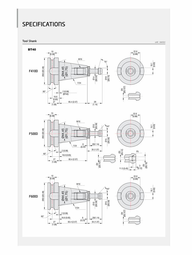
unit : mm(in)Tool Shank
Ø19
(Ø0.
784)
75°
Ø14
(Ø0.
551)
Ø63
(Ø2.
48)
65.4 (2.57)
6(0.23)
27(1.06)
2 (0.06)
Ø44
.45
(Ø1.
75)
35 (1.37)
29(1.14)
Ø15
(Ø0.
59)
60°
45°
16.6 (0.65)
22.6(0.89)
16.1
(0.63
)
7/24
M16
Ø10
(Ø0.
39)
10(0.39)
Ø3(Ø
0.12
)
Ø5(Ø
0.19
)
11.5 (0.45)3
(0.12)
P5
Ø63
(Ø2.
48)
65.4 (2.57)
6(0.23)27
(1.06)
2 (0.06)
Ø44
.45
(Ø1.
75)
35 (1.37)
29(1.14)
Ø15
(Ø0.
59)
60°
45°
16.6 (0.65)
22.6(0.89)
16.1
(0.63
)
7/24
M16
Ø10
(Ø0.
39)
10(0.39)
60°
Ø63.
5 (2.
5)
Ø3 (0
.118
)
Ø5 (0
.097
)
2. R0.4
11.5 (0.453)3 (0.118)
11.11(0.984)
25(0.984)
16.3
83(0.
645)
68.25 (2.687) 29 (1.142)
5/8″-11
Ø44.
5 (1.
75)
60°
Ø63.
5 (2.
5)
15 (0
.59)
25(0.984)
25(0.984)
16.3
83(0.
645)
68.25 (2.687) 32.15 (1.266)
5/8″-11
Ø44.
5 (1.
75)
60°
Ø63.
5 (2.
5)
15 (0
.59)
25(0.984)
25(0.984)
16.3
83(0.
645)
68.25 (2.687) 32.15 (1.266)
5/8″-11
Ø44.
5 (1.
75)
Ø63
(Ø2.
48)
65.4 (2.57)27(1.06)
2 (0.06)(BT40)
Ø44
.45
(Ø1.
75)
29(1.14)
Ø19
(Ø0.
75)
60°
75°
16.6(0.65)
22.6(0.88)
16.1
(0.63
)
7/24
M16
Ø14
(Ø0.
55)
10(0.39)
Ø4(Ø
0.15
7)
Ø2.7
″
Ø4(Ø
0.15
7)
Ø4(Ø
0.15
7)
Ø4 (0
.157
)
Ø4 (0
.157
)
F410D
F600D
F500D
BT40

SPECIFICATIONS
30+
31
FD
Ser
ieS
Vert
ical
Mac
hini
ng C
ente
rH
YUN
DAI
WIA
MAC
HIN
E TO
OL
unit : mm(in)Tool Shank
Ø19
(Ø0.
784)
75°
Ø14
(Ø0.
551)
Ø63
(Ø2.
48)
65.4 (2.57)
6(0.23)
27(1.06)
2 (0.06)
Ø44
.45
(Ø1.
75)
35 (1.37)
29(1.14)
Ø15
(Ø0.
59)
60°
45°
16.6 (0.65)
22.6(0.89)
16.1
(0.63
)
7/24
M16
Ø10
(Ø0.
39)
10(0.39)
Ø3(Ø
0.12
)
Ø5(Ø
0.19
)
11.5 (0.45)3
(0.12)
P5
Ø63
(Ø2.
48)
65.4 (2.57)
6(0.23)27
(1.06)
2 (0.06)
Ø44
.45
(Ø1.
75)
35 (1.37)
29(1.14)
Ø15
(Ø0.
59)
60°
45°
16.6 (0.65)
22.6(0.89)
16.1
(0.63
)
7/24
M16
Ø10
(Ø0.
39)
10(0.39)
60°Ø6
3.5
(2.5)
Ø3 (0
.118
)
Ø5 (0
.097
)
2. R0.4
11.5 (0.453)3 (0.118)
11.11(0.984)
25(0.984)
16.3
83(0.
645)
68.25 (2.687) 29 (1.142)
5/8″-11
Ø44.
5 (1.
75)
60°
Ø63.
5 (2.
5)
15 (0
.59)
25(0.984)
25(0.984)
16.3
83(0.
645)
68.25 (2.687) 32.15 (1.266)
5/8″-11
Ø44.
5 (1.
75)
60°
Ø63.
5 (2.
5)
15 (0
.59)
25(0.984)
25(0.984)
16.3
83(0.
645)
68.25 (2.687) 32.15 (1.266)
5/8″-11
Ø44.
5 (1.
75)
Ø63
(Ø2.
48)
65.4 (2.57)27(1.06)
2 (0.06)(BT40)
Ø44
.45
(Ø1.
75)
29(1.14)
Ø19
(Ø0.
75)
60°
75°
16.6(0.65)
22.6(0.88)
16.1
(0.63
)
7/24
M16
Ø14
(Ø0.
55)
10(0.39)
Ø4(Ø
0.15
7)
Ø2.7
″
Ø4(Ø
0.15
7)
Ø4(Ø
0.15
7)
Ø4 (0
.157
)
Ø4 (0
.157
)
F410D
F600D
F500D
CAT40

SPECIFICATIONS
Specifications [ ] : Option
ITEM F410D F500D
TABLE
Table Size mm(in) 2-650×410(2-25.6″×16.1″) 2-700×500(2-27.6″×19.7″)
Maximum Load Capacity kg(lb) 2-250(2-551.2) 2-350(2-771.6)
Table Change Time sec 5.2 6
Change Method - RotaryTurn
Table Driving Method - Rack&Pinion
SPINDLE
Spindle Taper - NT#40
Spindle RPM r/min 10,000[10,000] 8,000[10,000][12,000][8,000]
Spindle Power Output (Max./Cont.) kW(HP) 18.5/15(24.8/20)[22.5/15(30.2/20)] 15/11(20/14.7)[15/11(20/14.7)][11/7.5(14.7/10)][43/18.5(57.7/24.8]
Spindle Torque (Max./Cont.) N・m(lbf・ft) 117.7/95.4(86.8/70.4)[189/126(139.4/92.9)] 287/143(211.7/105.5[230/115(170/84.8][70/47(51.6/34.7)][300/157(221.2/115.8)]
Spindle Driving Method - BELT[BELT] BELT[BELT][BELT][DIRECT]
FEED
Travel (X/Y/Z) mm(in) 570/410/580(22.4″/16.1″/22.8″) 600/460/570(23.6″/18.1″/22.4″)
Distance from Table Surface to SP mm(in) 197~777(7.8″~30.6″) 200~770(7.9″~30.3″)
Distance from Column to SP. center mm(in) 495(19.5″) 500(19.7″)
Rapid Traverse Rate (X/Y/Z) m/min(ipm) 36/36/30(1,417/1,417/1,181) 40/40/30(1,575/1,575/1,181)
Slide Type - LMGUIDE X/Y:ROLLERGUIDE,Z:BOXGUIDE
ATC
Number of Tools EA 24 24[30]
Tool Shank - BT40
Max. Tool Dia. (W.T / W.O) mm(in) Ø90/Ø150(3.5″/5.9″)
Max. Tool Length mm(in) 300(11.8″)
Max. Tool Weight kg(lb) 8(17.6)
Tool Selection Method - RANDOM
Tool Change TimeT-T sec 1.3 2.1
C-C sec 3.5 4.3
TANkCAPACITY
Coolant Tank ℓ(gal) 300(79.3)
Lubricating Tank ℓ(gal) 1.32(0.3) 3.1(0.8)
Hydraulic Tank ℓ(gal) 35(9.2) 60(15.9)
POWERSUPPLY
Air Consumption (0.5MPa) ℓ/min(gal) 400
Electric Power Supply KVA 30 28
Thickness of Power Cable Sq Over22 Over25
Voltage V/Hz 220/60(200/50*)
MACHINE
Floor Space (L×W) mm(in) 2,200×3,160(86.6″×124.4″) 2,710×2,930(106.7″×115.4″)
Height mm(in) 3,015(118.7″) 2,852(112.3″)
Weight kg(lb) 6,400(14,109.6) 9,500(20,943.9)
NC Controller - HWFiSeries[F32i-B][SIEMENS828D] HWFiSeries[F32i-A][SIEMENS828D]
*) Using 50Hz voltage instead of 60Hz may lower the output of motors. (excluding servo motors and inverter motors)Specifications are subject to change without notice for improvement.

Specifications
SPECIFICATIONS
32+
33
FD
Ser
ieS
Vert
ical
Mac
hini
ng C
ente
rH
YUN
DAI
WIA
MAC
HIN
E TO
OL
[ ] : Option
ITEM F600D
TABLE
Table Size mm(in) 2-900×650(2-35.4″×25.6″)
Maximum Load Capacity kg(lb) 2-400(2-881.8)
Table Change Time sec 8.5
Change Method - ROTARYTURN
Table Driving Method - RACk&PINION
SPINDLE
Spindle Taper - NT#40
Spindle RPM r/min 8,000[12,000]
Spindle Power Output (Max./Cont.) kW(HP) 15/11(20/14.7)[11/7.5(14.7/10)]
Spindle Torque (Max./Cont.) N・m(lbf・ft) 287/143(211.7/105.5)[70/47(51.6/34.7)]
Spindle Driving Method - BELT[DIRECT]
FEED
Travel (X/Y/Z) mm(in) 800/600/600(31.5″/23.6″/23.6″)
Distance from Table Surface to SP mm(in) 200~800(7.9″~31.5″)
Distance from Column to SP. center mm(in) 690(27.2″)
Rapid Traverse Rate (X/Y/Z) m/min(ipm) 42/42/42(1,653.5/1,653.5/1,653.5)
Slide Type - ROLLERGUIDE
ATC
Number of Tools EA 24[30]
Tool Shank - BT40
Max. Tool Dia. (W.T / W.O) mm(in) Ø90/Ø150(3.5″/5.9″)
Max. Tool Length mm(in) 300(11.8″)
Max. Tool Weight kg(lb) 8(17.6)
Tool Selection Method - RANDOM
Tool Change TimeT-T sec 2.0
C-C sec 4.2
TANkCAPACITY
Coolant Tank ℓ(gal) 600(158.5)
Lubricating Tank ℓ(gal) 3.1(0.8)
Hydraulic Tank ℓ(gal) 23(6.1)
POWERSUPPLY
Air Consumption (0.5MPa) ℓ/min(gal) 400
Electric Power Supply KVA 30
Thickness of Power Cable Sq Over25
Voltage V/Hz 220/60(200/50*)
MACHINE
Floor Space (L×W) mm(in) 2,720×3,620(107.1″×142.5″)
Height mm(in) 2,965(116.7″)
Weight kg(lb) 8,500(18,739.3)
NC Controller - HYUNDAIWIAFANUCiSeries[FANUC32i-A]
*) Using 50Hz voltage instead of 60Hz may lower the output of motors. (excluding servo motors and inverter motors)Specifications are subject to change without notice for improvement.

CONTROLLER
HYUNDAI WIA FANUC i SeriesControlled axis / Display / Accuracy Compensation
Controlled axis 3 axis (X, Y, Z)
Simultaneous controllable axis 3 axis(G00 & G01 : 3 axis, G02 & G03 : 2 axis)
Least input increment X, Y, Z축: 0.001 mm (0.0001″)Least command increment X, Y, Z축: 0.001 mm (0.0001″)Inch/Metric conversion G20 / G21Interlock Each axis / All axisMachine lock All axisEmergency stopStored stroke check 1 Over TrableStored stroke check 2Stored stroke check 3Follow-upServo off
Backlash compensation +/- 0~9999 pulse(rapid traverse & cutting feed)
Position switchStored pitch error compensationLCD/MDI 8.4″ color LCDOperationAutomatic operation (memory)MDI operationDNC operation Need DNC ProgramSearch function Sequence, ProgramProgram restartWrong operation preventionBuffer registerProgram check function Dry run, program checkSingle blockHandle interruptFeed functionsManual jog feed Rapid, Jog, handleManual handle feed-rate x1, x10, x100Feed command F code feedrate direct commandFeedrate override 0~200% (10% Unit)Jog feed 0~5,000 mm/min (197 ipm)Rapid traverse override F1, F25%, F50%, F100%Override cancel
Rapid traverse bell-shaped acceleration/deceleration
Auto corner override G62Program input & Interpolation functionsLabel SkipControl in/out
Nano Interpolation Positioning/Linear/Circular(G00/G01/G02/G03)
Exact stop mode/Exact stop G61 / G09Dwell G04, 0~9999.9999secHelical interpolationThreading/synchronous feed G33Manual reference point returnReference point return G28Reference point return check G272nd, 3rd, 4th Reference point return G30Program stop/end M00, M01 / M02, M30
Tape code EIA RS-244/ISO 840 (Automatic recognition)
Optional block skip 1 EAMax. programmable dimensions +/- 9999.9999 (+/- 8 digits)Program number O4 /N8Absolute/incremental command G90 / G91Decimal point inputPlane selection G17, G18, G19Work coordinate system setting G52~G59Work coordinate preset G50.3Additional work coordinate system G54.1 P1 ~P48 (48 pairs)Manual absolute "On" fixedProgrammable data input G10
Program input & Interpolation functions
Sub program call 10 folds nestedCustom macroAddition to custom macro common variables #100 ~ #199 , #500 ~ #999Cylinderical interpolation G02, G03Canned cycle G73, G74, G76, G80 ~ G89Optional chamfering/corner RSkip function G31High speed Skip functionAutomatic coordinate system settingCoordinate system rotation G68, G69Programmable mirror image G50.1, G51.1Single direction positioning G60External data input Tool offset, message, machine zero point shiftCylindrical interpolationAI advanced preview control G5.1 (20 Block look ahead)Polar coordinate command G15, G16Sub / Spindle functionsMiscellaneous function M3 digitsMiscellaneous function lockSpindle speed command S5 digits, binary outputSpindle speed override 50%~120% (10% unit)Spindle orientationRigid tappingTool functions / Tool compensationTool function Max. T8 digitsCutter compensation C G40~G42Tool length measurement Z Axis INPUT CTool length compensation G43, G44, G49Tool offset amount G45~G48 (+/- 6 digits)Tool offset pairs 400 pairsTool life managementData input / Output & Editing functionsReader/Puncher interface RS232CMemory card input/outputUSB input/outputEmbeded Ethernet 100MbpsPart program storage length 1280m (512 Kbyte)Registered programs 400 eaMemory lockBack ground editingExtended part program editing Copy, move, change of NC programSetting, display, diagnosisSelf-diagnosis functionHistory display Alarm & operator messageHelp functionRun hour/Parts count displayActual cutting feedrate displaySpindle/Servo setting screenMulti-language display Selection of 5 optional languageDynamic switching display languageLCD Screen Save Screen saver
OptionSub Axis Control 4, 5 Axiswo way pitch error compensationManual Guide 0i 8.4″ color LCDManual Guide i 10.4″ color LCD (Conversational Program)Dynamic graphic displayOptional block skip add 9 ea (Application can be limited)AI contour control(AICC) 40 Block look aheadAI contour control(AICC) Ⅱ 200 Block look aheadNano SmoothingTool Management FunctionProtection of data at 8 levelsData server 1GBFASTethernet 100 Mbps (Option board is required)Part program storage length Expand 5120m (2 Mbyte)
Figures in inch are converted from metric values.The FANUC controller specifications are subject to change based on the policy of company CNC supplying.

CONTROLLER
34+
35
FD
Ser
ieS
Vert
ical
Mac
hini
ng C
ente
rH
YUN
DAI
WIA
MAC
HIN
E TO
OL
SIEMENS 828D (F410D | F500D)Control Function
Max. configuration of axis 5 axisMax. configuration of axis and spindle 6 axis (axis + spindle)Least Command/input 0.0001mm / 0.00001inchFeed FunctionFeedrate Override 0 - 120%Rapid Traverse Override F0, 5, 25/50, 100%Acceleration with jerk limitationProgrammable accelerationFollow-up modeMeasuring system 1 and 2, selectableSeparate path feed for corners and chamfersTravel to fixed stopSpindle FunctionsSpindle Override 50% - 120%Spindle OrientationSpindle Speed LimitationRigid TappingInterpolationsLinear interpolation axis Max 4 axisCircle via center point and end point Circle via interpolation point Helical interpolation
Universal interpolator NURBS (non-uniform rational B splines)
Advanced Surface High Speed, High Rigidity FunctionCompressor for 3-axis machiningTool FunctionTool Radius Comp.Zero Offset (G54, G55, G56, G57 ,G58, G59) 100 EAProgrammable Zero Offset3D Tool Radius CompensationTool managementDisplayCRT / MDI 10.4˝ Color LCDScreen saverManual OperationManual Handle/Jog FeedRepositionReference Approach Ref 1, 2 ApproachSpindle Control Start, Stop, Rev, Jog, Ort. Auto OperationSingle BlockFeed HoldOptional Block SkipMachine LockDry RunSimulation 2DDiagnosis FunctionAlarm displaySpindle Load Meter/RPM Meter (monitor)PLC status/LAD display
Programming Function
Part Program Storage Length 5MBProgram Name 23 digitsSubroutine Call Protection LevelAbsolute/incremental Command G90 - G91Scaling, ROTInch / Metric ConversionConversational Cycle ProgramBlock SearchVariable Program (Macro)Read / Write System VariableBackGround EditingMiscellaneous Functions M - CodeLable Skip Program Stop / End M00, M01, M02, M30Lookahead , Jerk Limitation Feed & Forward Control
150 Block
SIEMENS Program exe.Maximum number of tools/cuttings 256/512Number of levels for skip blocks 1Protection FunctionEmergency StopOver Travel Soft LimitContour MonitoringProgram ProtectionAutomation Support Fun.Actual Speed Display(Monitor)Tool Life Management (Time, Parts)Work Count Function (Internal)Language Function
Two Language switchable
(6EA)Chinese Traditional, Czech, Danish,Dutch, Finnish, Hungarian, Japanese,Korean, Polish, Russian, Swedish,Portuguese, Turkish
Data TransferRS 232C I/F / EthernetEthernetUSB Memory Stick & CF Card
OptionDRF offsetLoad and save of MDITeach-inNumber of levels for skip blocks 8 Simulation in 3D displayShop Mill Conversational ProgramTRACYLTRANSMIT
Figures in inch are converted from metric values.The SIEMENS controller specifications are subject to change based on the policy of company CNC supplying.

CONTROLLER
FANUC 32i-B (F410D)Controlled axis / Display / Accuracy CompensationControl axes 3 axes (X, Y, Z) 4 axes (X, Y, Z, B)Simultaneously controlled axes 3 axes [Max. 4 axes]
Least setting UnitX, Y, Z axes : 0.001 mm (0.0001 inch) B axes : 1 deg [0.001] deg
Least input incrementX, Y, Z axes : 0.001 mm (0.0001 inch) B axes : 1 deg [0.001] deg
Inch / Metric conversion G20 / G21 High response vector controlInterlock All axes / Each axisMachine lock All axes
Backlash compensation ± 0 ~ 9999 pulses(Rapid traverse / Cutting feed)
Position switchLCD / MDI 10.4 inch color LCD Feedback Absolute motor feedback Stored stroke check 1 Over travel Stored pitch error compensationOperationAutomatic operation (Memory)MDI operationDNC operation Needed DNC software / CF cardProgram restartWrong operation prevention
Program check functionDry run, Program checkZ axes Machine lock, Stroek check before move
Single blockSearch function Program Number / Sequence Number Interpolation functionsNano interpolationPositioning G00 Linear interpolation G01 Cylinderical interpolation G02, G03 Exact stop mode Single : G09, Continuous : G61Dwell G04, 0 ~ 9999.9999 sec Skip G31
Reference position return1st reference : G282nd reference : G27Ref. position check : G30
Thread synchronous cutting G33 Helical interpolation Circular + Linear interpolation 2 axes(max.)Feed function / Acc. & Dec. control
Manual feed
Rapid traverseJog : 0~5,000mm/min (197 ipm)Manual handle : x1, x10, x100 pulsesReference position return
Cutting Feed command Direct input F codeFeedrate override 0 ~ 200% (10% Unit)Rapid traverse override F0% (F1%), F25%, F50%, F100% Override cancelFeed per minute G94 Feed per revolution G95
Look-ahead block40 Block200 Block (Mold)
Program inputTape Code EIA / ISO Optional block skip 1 ea Absolute / Incremental program G90 / G91 Program stop / end M00, M01 / M02, M30 Maximum command unit ± 999,999.999 mm (± 99,999.9999 inch)Plane selection X-Y : G17 / Z-X : G18 / Y-Z : G19Workpiece coordinate system G52, G53, 6 pairs (G54 ~ G59)Manual absolute Fixed ONProgrammable data input G10 Sub program call 10 folds nestedCustom macro #100 ~ #149, #500 ~ #549 G code system A Programmable mirror image G51.1, G50.1 G code preventing buffering G4.1 Including Chamfering / Corner RCanned cycle G73, G74, G76, G80 ~ G89 Coordinate rotation G68, G69
Auxiliary function / Spindle speed functionAuxiliary function M & 4 digitLevel-up M Code Multi / Bypass M codeSpindle speed command S & 5 digit , Binary outputSpindle override 0% ~ 150% (10% Unit)Spindle orientation M19 FSSB high speed rigid tappingTool function / Tool compensationTool function Max. T 8 digitTool life management 256 pairs ☆Tool offset pairs 64 pairsTool nose radius compensation G40, G41, G42 Tool nose length compensation G43, G44, G49 Tool offset memory C Tool length, diameter, abrasion(length, diameter)Tool length measurement Z axes Input CEditing functionPart program storage size 640m (256KB) No. of registerable programs 500 ea Program protectBackground editingExtended part program editing Copy, move and change of NC programMemory card program editData input / output & Interface
I/O interfaceRS 232C serial port, CF card, USB memoryEmbedded Ethernet interface
Screen hard copyExternal messageExternal key inputExternal workpiece number searchAutomatic data backupSetting, display and diagnosisSelf-diagnosis functionHistory display Alarm & Operator message & OperationRun hour / Parts count displayMaintenance informationActual cutting feedrate displayDisplay of spindle speed / T codeGraphic displayOperating monitor screen Spindle / Servo load etc.Power consumption monitoring Spindle & Servo Spindle / Servo setting screenMulti language display Support 20 languagesDisplay language switching Selection of 5 optional LanguagesLCD Screen Saver Screen saverProcessing select Speed/ridigity setting
OptionAdditional optional block skip 9 ea ☆Fast ethernet Needed option boardData server Needed option boardProtection of data at 8 levelsSub Spindle controlPolar coordinate command G15, G16Polar coordinate interpolation G12.1, G13.1Cylinderical interpolation G07.1 One-way positioning G60 Stored stroke check 2, 3Inverse-time feed G93 Scaling G50, G51 Manual guide i Conversational auto programHandle interruptManual handle feed 2/3 units
Additional custom macro variables#100~#199, #500~#999 #100~#199, #500~#999, #98000~#98499
Rigid tap ReturnTool management functionTool offset number Max. 400 pair Program storage capacity 512KB ~ 2MB Program registration number Max. 1000 ea Additional work coordinate 48 pair (G54.1 P1 ~ P48)
AICC Ⅱ200 block400 block ☆
[ ] : Option ☆ Needed technical consultation
Figures in inch are converted from metric values.The FANUC controller specifications are subject to change based on the policy of company CNC supplying.

36+
37
FD
Ser
ieS
Vert
ical
Mac
hini
ng C
ente
rH
YUN
DAI
WIA
MAC
HIN
E TO
OL
CONTROLLER
Axis control / Display unit
Controlled axis 3 axis (X, Y, Z)
Simultaneous controllable axis3 axis(G00 & G01 : 3 axis, G02 & G03 : 2 axis)
Least input increment X, Y, Z axis : 0.001mm (0.0001″)Least command increment X, Y, Z axis : 0.001mm (0.0001″) G20 / G21Inch / Metric conversion G20 / G21Interlock Each axis / All axisMachine lock All axisEmergency stopStored stroke check 1Mirror ImageFollow-upServo off
Backlash compensation+/- 0~9999 pulse(rapid traverse & cutting feed)
Position switchPitch error compensationLCD/MDI 10.4″ color LCDOperationAutomatic operation (memory)MDI operationResearch Function Sequence, ProgramProgram restartDry runSingle BlockBuffer registerMemory Card DNC operationFeed functionsManual jog feed Rapid, Jog, handleManual handle feed-rate x1, x10, x100Feed command F code feedrate direct commandFeedrate override 0~200% (10% Unit)Jog feed 0~5,000 mm/min (197 ipm)Rapid traverse override F0, F25%, F50%, F100%Override cancelRapid traverse bell-shaped acce/decelerationProgram input & Interpolation functionsLabel Skip
Interpolation functionPositioning/Linear/Circular(G00/G01/G02/G03)
Exact stop mode/Exact stop G61 / G09Control in/outDwellHelical interpolation G04, 0~9999.9999secThreading/synchronous feedManual reference point returnReference point returnReference point return check G282nd, Reference point return G27Program stop/end G30Tape code M00, M01 / M02, M30Optional block skip EIA / ISO (Automatic recognition)Max. programmable dimensions 1 eaProgram number +/- 9999.9999” (+/- 8digit)Sequence number O4 / N8 digitAbsolute/incremental commandDecimal point input G90 / G91Plane selection G17, G18, G19Work coordinate preset G52~G59Manual absolute “On” fixedProgrammable data input G10Sub program call 10 folds nested Custom macro
Program input & Interpolation functions
AI Contour Control(AICC) ICylinderical interpolationCanned cycleOptional chamfering/corner R G73, G74, G76, G80 ~ G89Skip functionAutomatic coordinate system setting G31Coordinate system rotationProgrammable mirror imageSub / Spindle functionsMiscellaneous function M3 digitMiscellaneous function lockSpindle speed command S5 digits, binary outputSpindle speed override 50% ~ 120% (10% Unit)Spindle orientationRigid tappingTool functions / Tool compensationTool function Max. T8 digitsCutter compensation C G40~G42Tool length compensation G43, G44, G49Tool offset pairs 64 PairTool life managementData input / Output & Editing functionsReader/Puncher interface RS232CMemory card input/outputEmbeded Ethernet 100 MbpsPart program storage length 320 m (128 Kbyte)Registered programs 125 eaMemory lockBack ground editingExtended part program editing Copy, move, change of NC programExtenal messageSetting, Display, DiagnosisSelf-diagnosis functionAlarm history display Alarm & MessageHelp functionRun hour/Parts count displayActual cutting feedrate displayGraphic displaySpindle/Servo setting screenOperation monitor screen Loadmeter LightSelection of 5 optional languageLCD Screen Save Screen saverAuto Data BackupManual Guide i Conversational Program
OptionSub Axis ControlAdditional work coordinate system 48 Pair / 300 PairAdditional custom micro change #100~#199, #500~#999Work coordinate CommandWork coordinate InterpolationCylinderical interpolationSingle direction positioning G60FAST ethernet 100 MbpsData server 1GBAI Contour Control II(AICC II)Additional optional blockskip 9 ea (Application can be limited)Handle interuptManual Handle Feed 3 unitProgram storage length 640m (256Kbyte) ~ 5120m (2Mbyte)Dynamic graphic displayProtection of data at 8 levelsTool monitoring function HWTM (Embeded FANUC Type)
FANUC 32i-A (F500D | F600D)
Figures in inch are converted from metric values.The FANUC controller specifications are subject to change based on the policy of company CNC supplying.

GLOBAL NETWORK

38+
39
FD
Ser
ieS
Vert
ical
Mac
hini
ng C
ente
rH
YUN
DAI
WIA
MAC
HIN
E TO
OL
OVERSEAS OFFICES
GLOBAL NETWORK
Changwon Technical Center / R&D Center / Factory153, Jeongdong-ro, Seongsan-gu, Changwon-si, Gyeongsangnam-do, Korea (Zip Code : 51533)TEL : +82 55 280 9114 FAX : +82 55 282 9680
Uiwang Technical Center / R&D Center37, Cheoldobangmulgwan-ro, Uiwang-si, Gyeonggi-do, Korea (Zip Code : 16082)TEL : +82 31 596 8209 Fax : +82 55 210 9804
HEADqUARTER
HYUNDAI WIAMachine Tools America 265, Spring Lake Drive, Itasca, IL, 60143
TEL : +1 630 625 5600 FAX : +1 630 625 4733
Jiangsu HYUNDAI WIACompany No.6 Fenghuang Road, Fenghuang Town, Zhangjjagang City, Jiangsu province, China
TEL : +86 512 5672 6808FAX : +86 512 5671 6960
Chengdu Branch OfficeNO.508 Room, B Block, AFC Plaza, NO.88 Jiaozi Road, High-tech Zone, Chengdu, China
TEL : +86 028 8665 2985FAX : +86 028 8665 2985
HYUNDAI WIAMachine Tools Europe Kaiserleipromenade 5, 63067 Offenbach, Germany
TEL : +49 69271 472 701FAX : +49 69271 472 719
Hyundai WIA Machine Tools ChinaShanghai Branch Office1-3F, Bldg6, No.1535 Hongmei Road, Xuhui District, Shanghai, China
TEL : +86 021 6427 9885FAX : +86 021 6427 9890
qingdao Branch OfficeRoom 1207, Cai Fu Building, 182-6 Haier Middle Road, Qingdao, China
TEL : +86 532 8667 9334FAX : +86 532 8667 9338
Raunheim Service CenterRaunheim R&D CenterFrankfurter. 63, 65479 Raunheim, Germany
TEL : +49 6142 9256 111 FAX : +49 6142 9256 100
Beijing Branch OfficeFloor 14, Zhonghangji Plaza B, No.15 Ronghua South Road, BDA Dist., Daxing Dist., Beijing, China 100176
TEL : +86 010 8453 9850FAX : +86 010 8453 9853
Wuhan Office306-2, A Tower,Jiayu Gpmggian, No12 Chuangye Road, Economic Development Zone, Wuhan, Hubei, China
TEL : +86 027 5952 3256FAX : +86 027 5952 3256
Inida Branch Office#4/169, Rajiv Gandhi Salai, (OMR), Kandanchavadi, Chennai-600 096, Tamilnadu, IndiaTEL: +91-44-3290-1719
Guangzhou Branch OfficeRoom 311, Unit 1-3, POLY TAL TU WUN, Hanxi Avenue, Panyu District, Guangzhou, China
TEL : +86 020 8550 6595 FAX : +86 020 8550 6597
Chongqing OfficeRoom 951, #3, Jinrongcheng T3, Jiangbei, Chongqing, China
TEL : +86 23 6701 2970

F500D MovieF410D Movie
Head Office & Factory153, Jeongdong-ro, Seongsan-gu, Changwon-si, Gyeongsangnam-do Tel +82 55 280 9500
Overseas Sales Team16F, 37, Cheoldobangmulgwan-ro, Uiwang-si, Gyeonggi-do Tel +82 31 593 8173
HYUNDAI WIA Machine Tools America265 Spring Lake Drive,Itasca, IL, 60143 Tel +1 (630) 625 5600 Fax +1 (630) 625 4733
HYUNDAI WIA Machine Tools EuropeKaiserleipromenade 5, D-63067 Offenbach, Germany Tel +49 69271 472 701 Fax +49 69271 472 719
Inida Branch Office#4/169, Rajiv Gandhi Salai, (OMR), Kandanchavadi, Chennai-600 096, Tamilnadu, India Tel +91 44 3290 1719
http://machine.hyundai-wia.com
2016-11 002.003 ENG


