User's GuideSNAU163C–August 2014–Revised October 2016
FDC1004EVM User's Guide
The FDC1004EVM evaluation kit is a plug and play system to test and evaluate the FDC1004, 4-Channelcapacitive to digital converter. The EVM is a breakable PCB which consists of 3 sections. The first sectionis a USB to I2C converter based on MSP430F5528 micro-controller, the second section contains theFDC1004 and the third section is a touchless sensor (to demonstrate the sensitivity of the FDC1004) . Thethird section can be removed and replace with customized sensors to evaluate the capabilities of theFDC1004 in various applications. The FDC1004EVM can be used with the Sensing Solutions EVM GUI.The software is able to configure the FDC1004’s registers, graph the measured values, and export thedata in CSV format.
2 Sensing Solutions EVM GUI ............................................................................................... 52.1 System Requirements.............................................................................................. 52.2 Installation Instructions............................................................................................. 52.3 Starting the GUI ................................................................................................... 122.4 Navigating the GUI ................................................................................................ 132.5 Connecting the EVM .............................................................................................. 152.6 Configuring the EVM Using the Register Page................................................................ 152.7 Configuring the EVM Using the Configuration Page.......................................................... 222.8 Streaming Measurement Data................................................................................... 232.9 Updating the EVM Firmware..................................................................................... 35
7 Software Installer In Progress.............................................................................................. 98 Device Driver Installer Wizard ............................................................................................. 99 Device Driver Installer In Progress....................................................................................... 1010 Device Driver Installer Completed ....................................................................................... 1111 Software Installer Completed ............................................................................................. 1112 Splash Screen .............................................................................................................. 1213 Introduction Page .......................................................................................................... 1314 Mouse Hovered Over Menu Button...................................................................................... 1415 Menu Display After Clicking Button ...................................................................................... 1416 FDC1004 Connected to GUI.............................................................................................. 1517 Selecting Auto-Read Interval on Register Page ....................................................................... 1618 Selecting a Register's Current Value for Editting on Register Page ................................................ 1719 Hovering Mouse Over Register Bit Value on Register Page ........................................................ 1820 Selecting a Register on Register Page.................................................................................. 1921 Reading the Current Device Register Value on Register Page ..................................................... 2022 Save Register Values to File on Register Page........................................................................ 2123 Loading Previously Saved Register Values from File on Register Page ........................................... 2224 Configuration Page......................................................................................................... 2325 Select the Data Graph on Data Streaming Page ...................................................................... 2426 Select Log File Button on Data Streaming Page....................................................................... 2527 Selected Log File Shown on Data Streaming Page ................................................................... 2628 Start Button on Data Streaming Page ................................................................................... 2729 Stop Button on Data Streaming Page ................................................................................... 2830 Show Statistics Button on Data Streaming Page ...................................................................... 2931 Hide Statistics Button on Data Streaming Page ....................................................................... 3032 Show Graph Configuration Button on Data Streaming Page......................................................... 3133 Graph Configuration Button on Data Streaming Page ................................................................ 3234 Hide Graph Configuration Button on Data Streaming Page .......................................................... 3335 Changing Number of Samples Displayed in Data Graph ............................................................ 3436 Displaying Previous Data Samples on the Data Streaming Page ................................................... 3537 Select TI-TXT File Button on Firmware Upload Page ................................................................ 3638 Selecting TI-TXT Firmware File for Upload to EVM .................................................................. 3739 Upload Firmware Button on Firmware Upload Page ................................................................. 3840 Firmware Upload in Progress ............................................................................................ 3841 Firmware Upload Success ............................................................................................... 3942 Top Layer Routing ......................................................................................................... 3943 Bottom Layer Routing ..................................................................................................... 3944 FDC1004EVM Schematic ................................................................................................. 40
List of Tables
1 Ordering....................................................................................................................... 12 J1, J2 Pin Out ................................................................................................................ 33 J4 Pin Out .................................................................................................................... 34 J5 Pin Out .................................................................................................................... 55 Bill of Materials ............................................................................................................. 41
TrademarksAll trademarks are the property of their respective owners.
1 SetupThis section provides a general description about FDC1004EVM, its I/O connectors and how to properlysetup the evaluation module.
1.1 FDC1004EVMThe FDC1004EVM is divided in three sections:1. USB to I2C section: this has the purpose to interface the communication of FDC1004 to a USB port.2. FDC1004 section: this section embeds FDC1004 capacitive to digital converter.3. Sensor section: this section contains a capacitive sensor that can be used for both human proximity
and simple gesture recognitions..
The EVM has precut lines on the borders of each section that allow for a flexible and specific systemdesign. As an example of the flexibility of this design, the sensor can be replaced with a customer sensor,or the MCU section can be separated to allow for a remote placement of the FDC1004.
Figure 1. FDC1004EVM : Sections
1.2 Input/Output Connector DescriptionJ1, J2: 4x1 Header: the I/O ports of sections between the USBtoI2C and the FDC1004 sections. Thisprovides the I2C communication channel and the power connections between these two sections shouldthe EVM be separated into sections. A simple 4 wire cable can be used to interface the sections.
J3: USB interface to connect the EVM to a PC; it also provides power to the EVM.
J4: 10x1 Headers. This is not populated by default. It provides an easy method to change sensors or toremotely place the sensor away from the FDC1004. This connector with its counterpart, J5, allows thecommunication of the two modules through a 10-wire cable.
Pin DescriptionJ5.1 GNDJ5.2 SHLD1J5.3 CIN1J5.4 Not ConnectedJ5.5 SHLD1J5.6 SHLD2J5.7 Not ConnectedJ5.8 CIN4J5.9 SHLD2J5.10 GND
1.3 HW SetupThe power supply of FDC1004 is provided by the LDO (U4), which is sourced from the USB 5.0V. The I2Ccommunication with FDC1004 is fully managed by the MSP430F5528IRGC microcontroller (U3). TheFDC1004 has a fixed I2C address.
2.1 System RequirementsThe host machine is required for device configuration and data streaming. The following steps arenecessary to prepare the EVM for the GUI:• The GUI and EVM driver must be installed on a host computer• - The EVM must be connected to a full speed USB port (USB 1.0 or above)
The Sensing Solutions EVM GUI supports the following operating systems (both 32-bit and 64-bit):• Windows XP• Windows 7• Windows 8 and 8.1• Windows 10
2.2 Installation InstructionsThe Sensing Solutions GUI and EVM driver installer is packaged in a zip file. Follow these steps to installthe software:1. Download the software ZIP file from the EVM tool page2. Extract the downloaded ZIP file3. Run the included executable4. If prompted by the User Account Control about making changes to the computer, click "Yes"
2.3 Starting the GUIFollow these steps to start the GUI:1. Select the Windows start menu2. Select "All programs"3. Select "Texas Instruments"4. Select "Sensing Solutions EVM GUI"5. Click "Sensing Solutions EVM GUI"6. Splash screen will appear for at least two seconds
Figure 12. Splash Screen
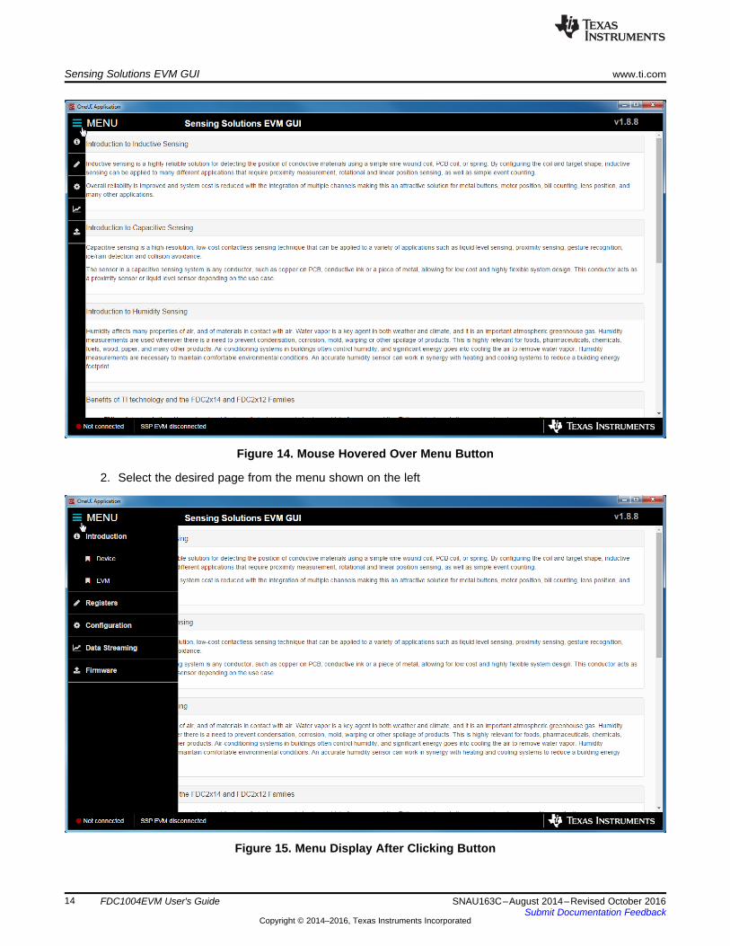
7. After the splash screen is displayed the main window will open
2.5 Connecting the EVMFollow these steps to connect the EVM to the GUI:1. Attach the EVM to the computer via USB2. The GUI always shows the connection status on the bottom left corner of the GUI
Figure 16. FDC1004 Connected to GUI
2.6 Configuring the EVM Using the Register PageThe register page allows users to control the device directly with the register values. The user may alsouse this page to read the currect register values on the device.
2.6.1 Automatically Update GUI Register Values Using Auto-ReadAutoread will periodically request the register values on the device. Click the dropdown box next to “AutoRead” to select the update interval.
Figure 17. Selecting Auto-Read Interval on Register Page
2.6.2 Manually Update Device Register ValuesThere are two methods to change register values: update the entire register value or change a single bitwithin the register. The recommended update mode is always “Immediate” and not “Deferred”. To updateregister values, follow these steps.1. Double-click the current value of the register that needs to be changed. The text will turn into an
Figure 18. Selecting a Register's Current Value for Editting on Register Page
2. Type the new hexadecimal value into the box and click enter. The text box changes to normal text andthe GUI will send a command to the EVM to update the device register
To change individual bit values rather that entire register values follow these steps.1. Hover the mouse over the desired bit to change
Figure 19. Hovering Mouse Over Register Bit Value on Register Page
2. Double-click the bit to toggle its value and the register’s current value will update automatically
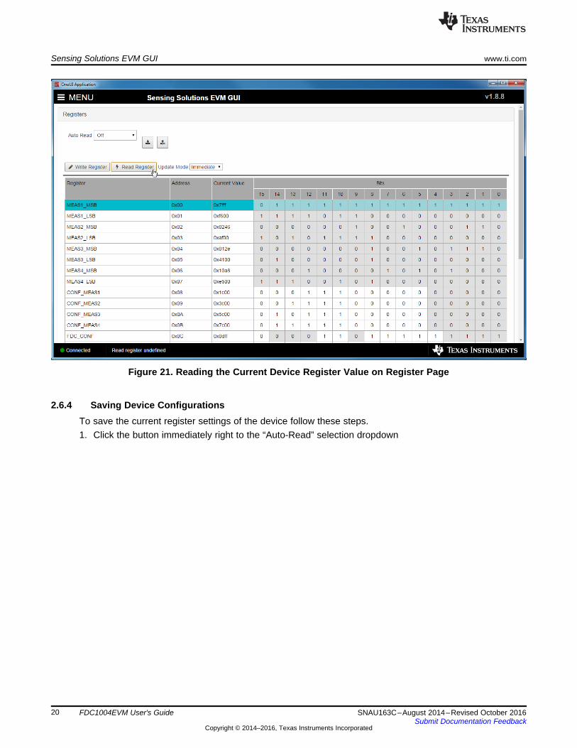
2.6.3 Reading Register Values without Auto-ReadTo read register values follow these steps.1. Select the register to update by clicking any column of the register row in the table
Figure 21. Reading the Current Device Register Value on Register Page
2.6.4 Saving Device ConfigurationsTo save the current register settings of the device follow these steps.1. Click the button immediately right to the “Auto-Read” selection dropdown
Figure 22. Save Register Values to File on Register Page
2. Choose a name for the JSON file and the directory to save it within. Then click “Save”
2.6.5 Loading Previously Saved ConfigurationsTo load previously saved register settings from a JSON file follow these steps.1. Click the button furthest right from the “Auto-Read” selection dropdown
Figure 23. Loading Previously Saved Register Values from File on Register Page
2. Select the JSON file with the desired settings and click “Open”
2.7 Configuring the EVM Using the Configuration PageThe Sensing Solutions GUI is capable on configuring the device more intuitively than the direct registervalues. The "Configuration" page provides an easy-to-use tool for updating the device configuration andprovides additional information about how the device will perform.
The FDC1004 measures in a round robin mode and can make up to four measurements. If all fourmeasurements are enabled and the sample rate is 400 samples per second new data for all fourmeasurements would be available at a rate of 100 Hz. If a single measurement were enabled rather thanall four, again with the sampling rate set to 400 samples per second, new data for the single measurementwould be available at a rate of 400 Hz.
To make a single measurement only once, select the measurement channel and click "TakeMeasurement". This will disable the "Enable continuous multi-channel measurements" setting. Continuousmeasurements must be enabled for the data streaming function of the GUI and EVM.
Please reference the FDC1004 datasheet for more information regarding individual measurement settings.
2.8 Streaming Measurement DataThe Sensing Solutions GUI and EVM provide a tool to capture, display, and log measurement data. Thesection describes how to use the data measurement tools from the "Data Streaming" page accessiblefrom the GUI menu.
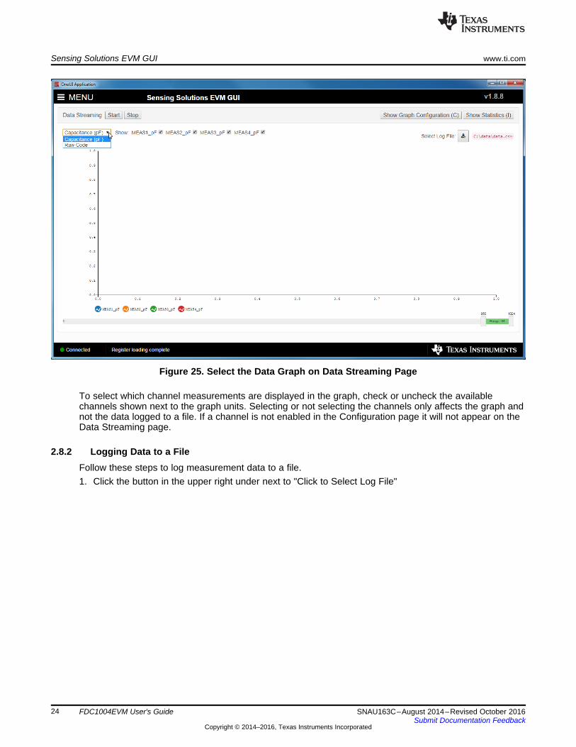
2.8.1 Choosing the Graph and Visible ChannelsSelect the drop down menu on top of the y-axis to choose the graph to display.
Figure 25. Select the Data Graph on Data Streaming Page
To select which channel measurements are displayed in the graph, check or uncheck the availablechannels shown next to the graph units. Selecting or not selecting the channels only affects the graph andnot the data logged to a file. If a channel is not enabled in the Configuration page it will not appear on theData Streaming page.
2.8.2 Logging Data to a FileFollow these steps to log measurement data to a file.1. Click the button in the upper right under next to "Click to Select Log File"
Figure 26. Select Log File Button on Data Streaming Page
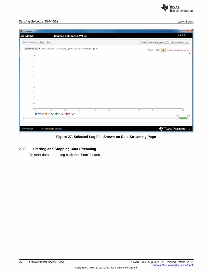
2. Select a file name and directory to save the data to and then click the “Save” button3. Whenever data streaming is running the data for all channels will be logged to this file. The selected
Figure 33. Graph Configuration Button on Data Streaming Page
The configuration window displays the actual frame rate of the graph, the rate at which data is added tothe graph, the vertical scaling, and the sample buffer size. The display rate is the rate at which the graphupdates on the computer display and is not configurable. It is automatically optimized by the GUI.
The "New Data Sample Rate" allows the user to choose when new data is added to the graph. Selecting"EVM Output Rate" will display data on the graph as fast as is available from the EVM. This should not beconfused with the actual sampling rate of the device on the EVM which could be different. The "Addsample to graph every ... ms" will add a new sample to the graph at the specified rate.
The "Verical Scaling" allows the user to either manually set the minimum and maximum values of the y-axis on the graph or use auto-scaling. The "Autoscale & Lock" button scales the graph based on the dataof the current display and then locks those vertical scaling settings.
The "Sample Counts" allows the user to specify the number of samples displayed on the graph and thetotal number of samples stored in the buffer. Please note the buffer size does not affect data logging to afile.
To hide the configuration window, click the "Hide Graph Configuration" button.
Figure 34. Hide Graph Configuration Button on Data Streaming Page
2.8.6 Navigating the Data Streaming BufferThe Sensing Solutions EVM GUI stores a buffer of data samples and then displays a subset of thosesamples. The data buffer can be navigated using the horizontal slider below the graph. To show moresamples on the graph, click either the slider on the left or right side of the green bar and drag it closer orfurther from the other slider. The number of samples displayed is shown between the left and right slidersin the green bar.
Figure 36. Displaying Previous Data Samples on the Data Streaming Page
2.9 Updating the EVM FirmwareTo upload new firmware to the EVM, navigate to the "Firmware" page from the GUI menu and follow thesesteps. The images below show uploading the FDC2214 EVM firmware, but the steps are identical for anyLDC, FDC, or HDC EVM when using their respective firmware files.1. Click the button to select a TI-TXT firmware file
Figure 39. Upload Firmware Button on Firmware Upload Page
4. Wait for the firmware to upload. Do NOT disconnect the EVM from the PC at this time! Also note thatthe GUI will disconnect from the EVM. The upload process should not take more than one minute. Ifthe upload fails or lasts longer than one minute, unplug the EVM and restart the GUI.
3 Board LayoutFigure 42 and Figure 43 show the board layout of the FDC1004EVM.
Sensor layout has been designed to demonstrate the possible trade-off between sensor sensitivity andprotection from interferences. SHLD1 surrounds "LEFT" sensor and it has a bigger area than SHLD2 thatsurrounds "RIGHT" sensor. As a consequence, the "LEFT" sensor is better shielded from interferencesbut at the cost of lower sensitivity.
Revision HistoryNOTE: Page numbers for previous revisions may differ from page numbers in the current version.
Changes from B Revision (August 2014) to C Revision ................................................................................................ Page
• Changed Sensing Solutions EVM GUI section........................................................................................ 5• Changed Updated Part Number ....................................................................................................... 41
Changes from A Revision (August 2014) to B Revision ...................................................................................................... Page• Added Description of the sensor....................................................................................................... 39
Changes from Original (August 2014) to A Revision ........................................................................................................... Page• Changed photo of board ................................................................................................................. 1
IMPORTANT NOTICE FOR TI DESIGN INFORMATION AND RESOURCES
Texas Instruments Incorporated (‘TI”) technical, application or other design advice, services or information, including, but not limited to,reference designs and materials relating to evaluation modules, (collectively, “TI Resources”) are intended to assist designers who aredeveloping applications that incorporate TI products; by downloading, accessing or using any particular TI Resource in any way, you(individually or, if you are acting on behalf of a company, your company) agree to use it solely for this purpose and subject to the terms ofthis Notice.TI’s provision of TI Resources does not expand or otherwise alter TI’s applicable published warranties or warranty disclaimers for TIproducts, and no additional obligations or liabilities arise from TI providing such TI Resources. TI reserves the right to make corrections,enhancements, improvements and other changes to its TI Resources.You understand and agree that you remain responsible for using your independent analysis, evaluation and judgment in designing yourapplications and that you have full and exclusive responsibility to assure the safety of your applications and compliance of your applications(and of all TI products used in or for your applications) with all applicable regulations, laws and other applicable requirements. Yourepresent that, with respect to your applications, you have all the necessary expertise to create and implement safeguards that (1)anticipate dangerous consequences of failures, (2) monitor failures and their consequences, and (3) lessen the likelihood of failures thatmight cause harm and take appropriate actions. You agree that prior to using or distributing any applications that include TI products, youwill thoroughly test such applications and the functionality of such TI products as used in such applications. TI has not conducted anytesting other than that specifically described in the published documentation for a particular TI Resource.You are authorized to use, copy and modify any individual TI Resource only in connection with the development of applications that includethe TI product(s) identified in such TI Resource. NO OTHER LICENSE, EXPRESS OR IMPLIED, BY ESTOPPEL OR OTHERWISE TOANY OTHER TI INTELLECTUAL PROPERTY RIGHT, AND NO LICENSE TO ANY TECHNOLOGY OR INTELLECTUAL PROPERTYRIGHT OF TI OR ANY THIRD PARTY IS GRANTED HEREIN, including but not limited to any patent right, copyright, mask work right, orother intellectual property right relating to any combination, machine, or process in which TI products or services are used. Informationregarding or referencing third-party products or services does not constitute a license to use such products or services, or a warranty orendorsement thereof. Use of TI Resources may require a license from a third party under the patents or other intellectual property of thethird party, or a license from TI under the patents or other intellectual property of TI.TI RESOURCES ARE PROVIDED “AS IS” AND WITH ALL FAULTS. TI DISCLAIMS ALL OTHER WARRANTIES ORREPRESENTATIONS, EXPRESS OR IMPLIED, REGARDING TI RESOURCES OR USE THEREOF, INCLUDING BUT NOT LIMITED TOACCURACY OR COMPLETENESS, TITLE, ANY EPIDEMIC FAILURE WARRANTY AND ANY IMPLIED WARRANTIES OFMERCHANTABILITY, FITNESS FOR A PARTICULAR PURPOSE, AND NON-INFRINGEMENT OF ANY THIRD PARTY INTELLECTUALPROPERTY RIGHTS.TI SHALL NOT BE LIABLE FOR AND SHALL NOT DEFEND OR INDEMNIFY YOU AGAINST ANY CLAIM, INCLUDING BUT NOTLIMITED TO ANY INFRINGEMENT CLAIM THAT RELATES TO OR IS BASED ON ANY COMBINATION OF PRODUCTS EVEN IFDESCRIBED IN TI RESOURCES OR OTHERWISE. IN NO EVENT SHALL TI BE LIABLE FOR ANY ACTUAL, DIRECT, SPECIAL,COLLATERAL, INDIRECT, PUNITIVE, INCIDENTAL, CONSEQUENTIAL OR EXEMPLARY DAMAGES IN CONNECTION WITH ORARISING OUT OF TI RESOURCES OR USE THEREOF, AND REGARDLESS OF WHETHER TI HAS BEEN ADVISED OF THEPOSSIBILITY OF SUCH DAMAGES.You agree to fully indemnify TI and its representatives against any damages, costs, losses, and/or liabilities arising out of your non-compliance with the terms and provisions of this Notice.This Notice applies to TI Resources. Additional terms apply to the use and purchase of certain types of materials, TI products and services.These include; without limitation, TI’s standard terms for semiconductor products http://www.ti.com/sc/docs/stdterms.htm), evaluationmodules, and samples (http://www.ti.com/sc/docs/sampterms.htm).


![OFDM error floor based EVM estimation Error Floor Based EVM Estimation.pdfAWGN source producing the same BER (and EVM) degradation. [1]: The resulting EVM(BER) curves were verified](https://static.documents.pub/doc/80x56/5f2e7bc463c3260b31328bb2/ofdm-error-floor-based-evm-estimation-error-floor-based-evm-awgn-source-producing.jpg)


