57
Technology Overview Peter Overgaauw - Honeywell IFEA September 19, 2012 FDT – DTM and eDDL

Technology Overview Peter Overgaauw - Honeywell
IFEA
September 19, 2012
FDT – DTM and eDDL

2 HONEYWELL September 19, 2012
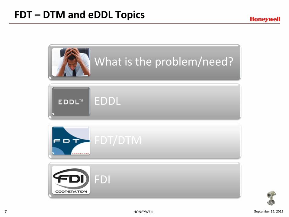
FDT – DTM and eDDL Topics
What is the problem/need?
EDDL
FDT/DTM
FDI
3 HONEYWELL September 19, 2012
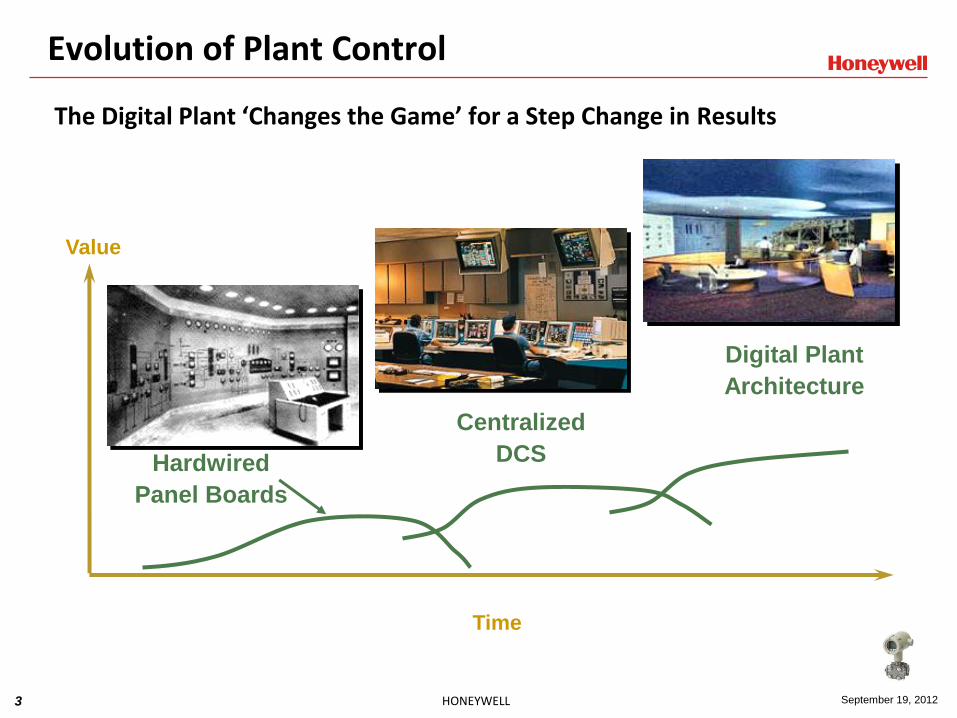
Evolution of Plant Control
Value
Centralized
DCS Hardwired
Panel Boards
Digital Plant
Architecture
Time
The Digital Plant ‘Changes the Game’ for a Step Change in Results

4 HONEYWELL September 19, 2012
Temperature Transmitter Example
Device data is described by VARIABLE, RECORD and ARRAY constructs in the DD file.
The host typically displays the device data as a list.
Device DD File
Classic DD file behaviour

5 HONEYWELL September 19, 2012
Application on PC or Handheld Reads DD
Values
are read from
the device.
25.50
Digits of precision
Engineering Unit
Label of the value
Measured_Value
%
Application on PC or Handheld
uses the same DD
Descriptions for values are obtained from the DD.
DD

6 HONEYWELL September 19, 2012
DD File History
1997 1990
2000
2003
1992
1988
1996
First Intelligent
Hart Devices
EDDL definition in the
International Fieldbus Group
EDDL Standard in the HART
Communication Foundation
EDDL Standard in the Fieldbus
Foundation
first PROFIBUS devices are
described with EDDL
EDDL gets PNO standard
Standardization in CENELEC
7 HONEYWELL September 19, 2012
FDT – DTM and eDDL Topics
What is the problem/need?
EDDL
FDT/DTM
FDI

8 HONEYWELL September 19, 2012
The DD Cooperation Project was approved by FF, PNO and HCF in October 2002 to specify Electronic Device Description (EDD) visualization and data storage management extensions.
Common EDD extensions for FOUNDATION fieldbus, PROFIBUS and HART preserves and protects the worldwide investment in EDD-based devices, tools and training.
DD Cooperation Project

9 HONEYWELL September 19, 2012
DD Cooperation Project
10 HONEYWELL September 19, 2012
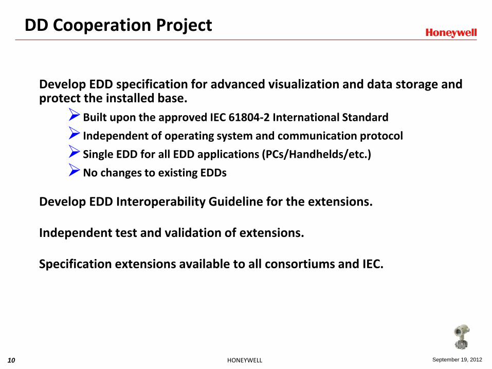
Develop EDD specification for advanced visualization and data storage and protect the installed base.
Built upon the approved IEC 61804-2 International Standard
Independent of operating system and communication protocol
Single EDD for all EDD applications (PCs/Handhelds/etc.)
No changes to existing EDDs
Develop EDD Interoperability Guideline for the extensions. Independent test and validation of extensions. Specification extensions available to all consortiums and IEC.
DD Cooperation Project
11 HONEYWELL September 19, 2012
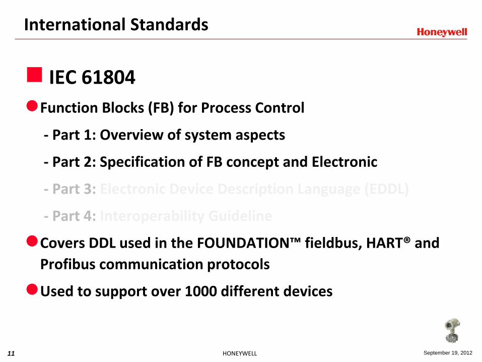
International Standards
IEC 61804
Function Blocks (FB) for Process Control
- Part 1: Overview of system aspects
- Part 2: Specification of FB concept and Electronic
- Part 3: Electronic Device Description Language (EDDL)
- Part 4: Interoperability Guideline
Covers DDL used in the FOUNDATION™ fieldbus, HART® and
Profibus communication protocols
Used to support over 1000 different devices
12 HONEYWELL September 19, 2012
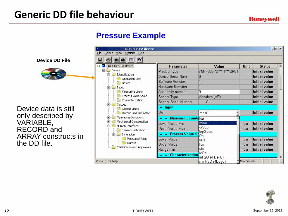
Pressure Example
Device data is still only described by VARIABLE, RECORD and ARRAY constructs in the DD file.
Device DD File
Generic DD file behaviour

13 HONEYWELL September 19, 2012
International Standards
IEC 61804
Function Blocks (FB) for Process Control
- Part 1: Overview of system aspects
- Part 2: Specification of FB concept and Electronic
- Part 3: Electronic Device Description Language (EDDL)
- Part 4: Interoperability Guideline
Covers DDL used in the FOUNDATION™ fieldbus, HART® and
Profibus communication protocols
Used to support over 100’s different devices

14 HONEYWELL September 19, 2012
DD Cooperation Project
•Enhanced User Interface Parameter organization Windows, dialogs, group boxes Images
Graphing System Visualize complex data Support for charts and graphs Multiple plots Interactive zooming Direct editing of graphs Emphasis, key points, notes
Persistent Data Storage Store/access device data on the host
Independent of host file system
Valve diagnostics
Sensor drift
Sensor/Actuator diagnostics
Archived valve signatures
Radar level configuration
Valve signatures
Sensor/Actuator configuration
Motor control
Complex configurations
Applications
15 HONEYWELL September 19, 2012
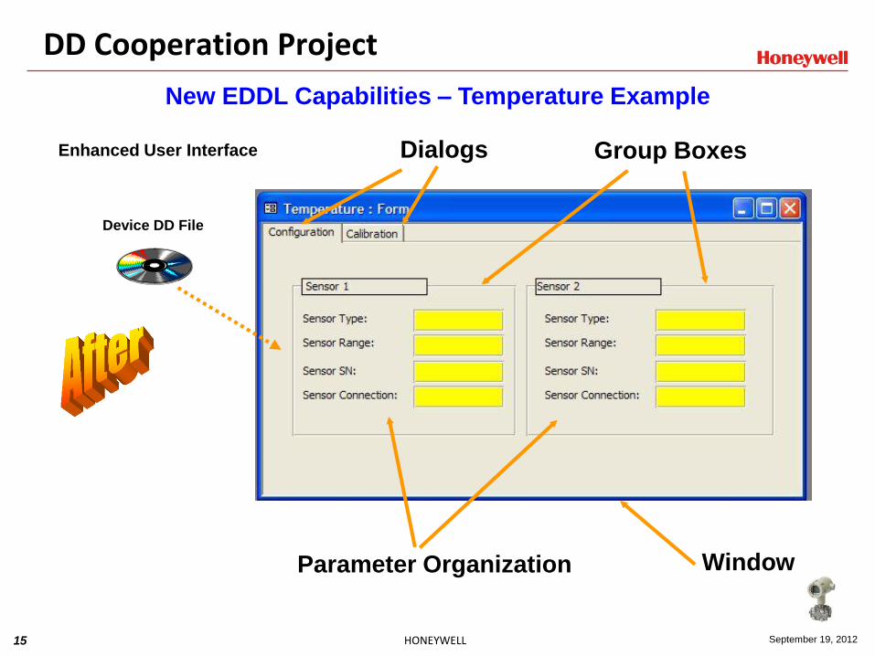
New EDDL Capabilities – Temperature Example
Device DD File
Enhanced User Interface
Parameter Organization
Group Boxes Dialogs
Window
DD Cooperation Project

16 HONEYWELL September 19, 2012
A GRAPH is used to present the echo WAVEFORM to enable configuration of thresholds and false echoes areas in the device.
Trigger device to build
WAVEFORM data
Retrieve WAVEFORM data
Update the GRAPH
GRAPH
WAVEFORM
(Data from Device) AXIS
MENUS & METHODS
(Enhanced UI)
Radar Gauge
Threshold
Calibration
DD Cooperation Project
ARRAY(s)
(Device Data)
FILE/LIST
(Persistent Data)
Echo Curve
Filter
DD Cooperation Project
New EDDL Capabilities – Radar Gauge Step Example
17 HONEYWELL September 19, 2012
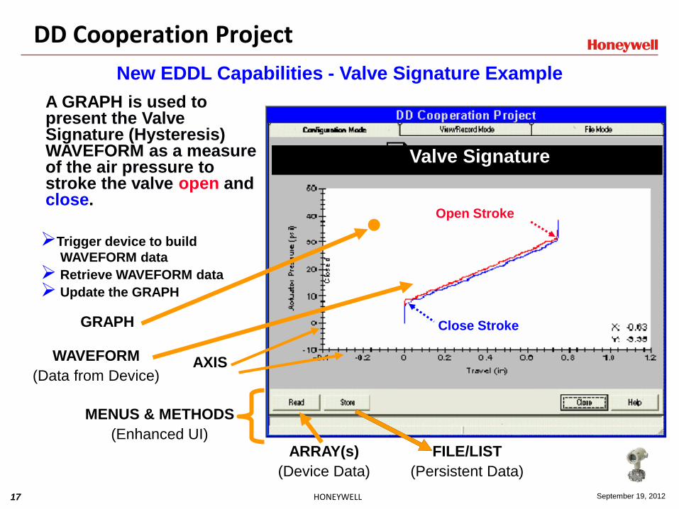
New EDDL Capabilities - Valve Signature Example
A GRAPH is used to present the Valve Signature (Hysteresis) WAVEFORM as a measure of the air pressure to stroke the valve open and close.
Trigger device to build
WAVEFORM data
Retrieve WAVEFORM data
Update the GRAPH
Blue line is a reference retrieved
via FILE and ARRAY
GRAPH
WAVEFORM
(Data from Device)
ARRAY(s)
(Device Data)
AXIS
MENUS & METHODS
(Enhanced UI) FILE/LIST
(Persistent Data)
Valve Signature
Open Stroke
Close Stroke
DD Cooperation Project

18 HONEYWELL September 19, 2012
New EDDL Capabilities – Valve Step Example
ARRAY(s)
(Device Data)
MENUS & METHODS
(Enhanced UI) FILE
(Persistent Data)
A CHART is used to present the Real-time (continuous) Step Response SOURCE of a valve.
Trigger device to build
SOURCE data
Retrieve SOURCE data
Update the CHART
Blue line is a reference retrieved
via FILE and ARRAY
CHART
SOURCEs
(Stored Data and
Data from Device) AXIS
Valve Step Response Diagnostics
Travel (From device)
Setpoint (Stored)
DD Cooperation Project
19 HONEYWELL September 19, 2012
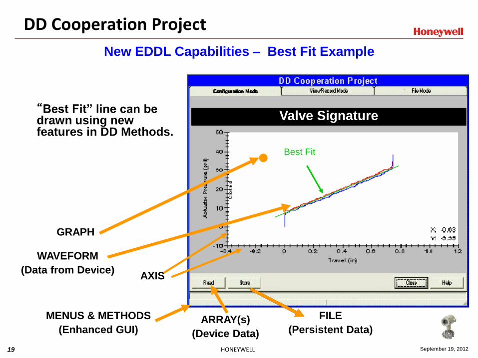
New EDDL Capabilities – Best Fit Example
Blue line is a reference retrieved
via FILE and ARRAY
GRAPH
WAVEFORM
(Data from Device)
ARRAY(s)
(Device Data)
AXIS
MENUS & METHODS
(Enhanced GUI)
FILE
(Persistent Data)
Best Fit
“Best Fit” line can be drawn using new features in DD Methods.
Valve Signature
DD Cooperation Project

20 HONEYWELL September 19, 2012
Image
Enhanced MENUS and METHOD are used to build dialog boxes displaying motor starts, operating hours, number of overload trips, etc.
MOTOR
SYMMETRY
MOTOR PARAMETERS
Static bit map
Objective is to provide a visual representation of the parameters
DD Cooperation Project
New EDDL Capabilities – Motor Symetry Example

21 HONEYWELL September 19, 2012
Examples of new EDDL Displays
• Integration technology for device setup and maintenance
22 HONEYWELL September 19, 2012
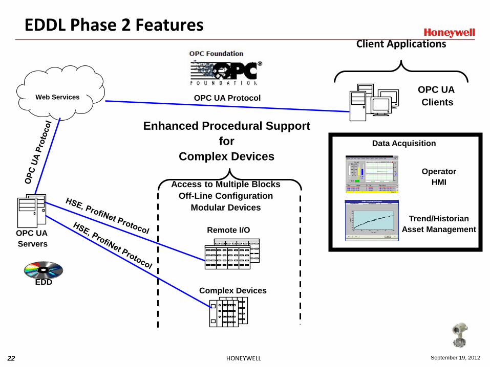
EDDL Phase 2 Features Client Applications
OPC UA
Servers
Complex Devices
Web Services
OPC UA
Clients
Trend/Historian
Asset Management
Blue line is a reference retrieved
via FILE and ARRAY
EDDL Cooperation Project
Blue line is a reference retrieved
via FILE and ARRAY
EDDL Cooperation Project
Blue line is a reference retrieved
via FILE and ARRAY
EDDL Cooperation Project
Operator
HMI
Remote I/O
Access to Multiple Blocks
Off-Line Configuration
Modular Devices
OPC UA Protocol
EDD
Data Acquisition
Enhanced Procedural Support
for
Complex Devices
23 HONEYWELL September 19, 2012
FDT – DTM and eDDL Topics
What is the problem/need?
EDDL
FDT/DTM
FDI
24 HONEYWELL September 19, 2012
The Original Customer Needs…
• Users want to use best-in-class devices, generally from multiple vendors.
• Most vendor’s devices became more powerful (and complex) with diagnostic features and functions built-in.
• Users need asset performance management to help: - improve uptime,
- better utilize staff
- optimize field device utilization
25 HONEYWELL September 19, 2012
History Lesson – How did we get here?
• October 2002 - The DD Cooperation Project was launched.
- Original Members: • Honeywell, ABB, Emerson Process Management, Endress+Hauser,
FlowServe, Invensys, Siemens and Yokogawa.
- Goal was to extend the concept of interoperability into the HMI and diagnostic data areas.
- DDs have been used for more than 10 years but lacked the ability to work with more complex capabilities like valve signatures, sensor calibration curves and data storage management.
26 HONEYWELL September 19, 2012
• 1998 - First FDT/DTM created
• January 2003 - FDT/DTM was standardized by the FDT Joint Interest Group
• ABB, Endress+Hauser, Invensys, Siemens and Metso Automation • Membership now exceeds 31 members
• April 2003 - FDT Joint Interest Group
• ABB, Endress+Hauser, Invensys, Siemens, Metso
• April 2007 - FDT joined ECT as an official member
• ECT = FF, HCF and OPC Foundation
- FDT and EDDL technologies will eventually merge.
History Lesson – How did we get here?
27 HONEYWELL September 19, 2012
Definitions
• FDT/DTM - Provides an open framework for field device maintenance and
configuration software.
- Works with any field bus application.
• FDT
- Field Device Tool • A standardized software interface description that defines the co-
operation between device management plug-ins (DTMs) and an FDT container.
• DTM
- Device Type Manager • A DTM is a device maintenance and diagnostic application that plug’s
into a host system’s engineering and asset management system.

28 HONEYWELL September 19, 2012
FDT Structure
• FDT Defines: - A set of software component interfaces
- Responsibilities between components
- Components: frame application, device drivers and communication drivers
• An FDT solution consist of three major components: - The “frame application” that provides the common container and
user interface function
- The “device software” that for each instrument that appears as a window pane within the frame
- The “communications software” that passes the communications through the system to the device
29 HONEYWELL September 19, 2012
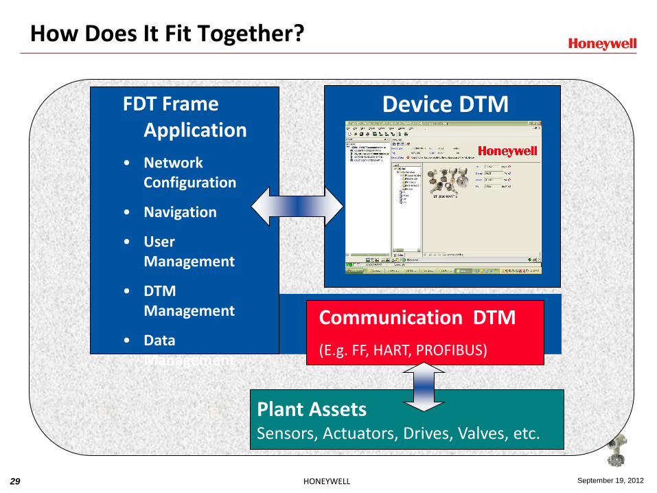
How Does It Fit Together?
Device DTM FDT Frame Application
• Network Configuration
• Navigation
• User Management
• DTM Management
• Data Management
Communication DTM
(E.g. FF, HART, PROFIBUS)
Plant Assets Sensors, Actuators, Drives, Valves, etc.

30 HONEYWELL September 19, 2012
Characteristics of a DTM
• Similar to a “printer driver” on the office world
• Are available from each device manufacturer
• Provides graphical support for operation
• Allows off-line and on-line configuration parameter
adjustment(s)
• Supports the instrument’s diagnostic options
• Can provide documentation of the instrument settings
• Can provide “on-line” help
31 HONEYWELL September 19, 2012
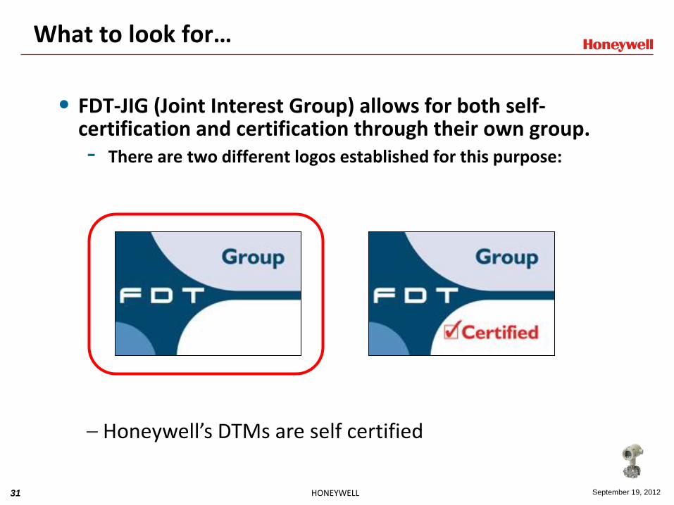
What to look for…
• FDT-JIG (Joint Interest Group) allows for both self-certification and certification through their own group. - There are two different logos established for this purpose:
– Honeywell’s DTMs are self certified
32 HONEYWELL September 19, 2012
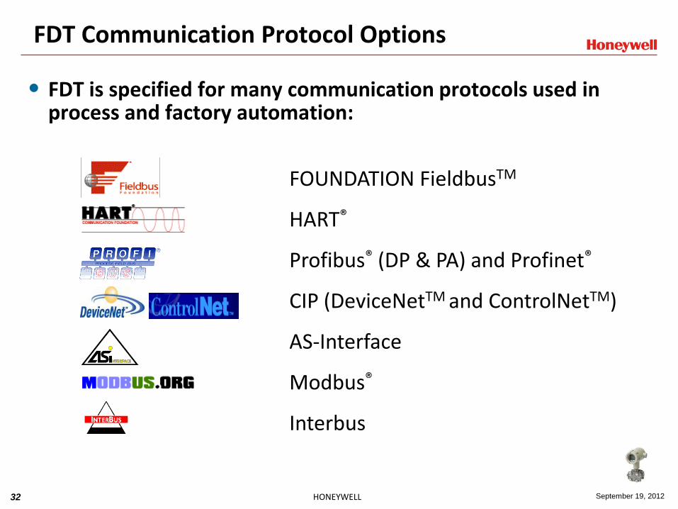
FDT Communication Protocol Options
• FDT is specified for many communication protocols used in process and factory automation:
FOUNDATION FieldbusTM
HART®
Profibus® (DP & PA) and Profinet®
CIP (DeviceNetTM and ControlNetTM)
AS-Interface
Modbus®
Interbus
33 HONEYWELL September 19, 2012
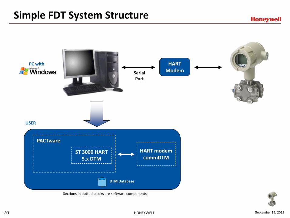
Simple FDT System Structure
USER
Serial Port
PC with Windows XP
ST 3000 HART 5.x DTM
HART modem commDTM
Sections in dotted blocks are software components
HART Modem
DTM Database
PACTware

34 HONEYWELL September 19, 2012
HART Device
Experion FDM System Structure
Ethernet / FTE
FDM (Server)
HART DTM Database
HART Protocol
(MTL, P+F, R.Stahl, Elcon, Arcom)
Hardware Mux
EPKS Server
SW MUX
CIOM-A (1756) AI/AO
EPKS ERDB
ControlNet/FTE
Redundant PMIO AI/AO
HART devices HART
devices
FDM (Client)
FDM (RCI)
RS-232
RS-232
RS-485 Hardware MUX
Redundant Series C AI/AO
Up to 10,240 devices / EPKS Server Up to 7,936 devices / Hard-MUX
HART Device
RS-232
RS-232
RS-485
HART Modem
HART Modem

35 HONEYWELL September 19, 2012
Frame Application
• The FDT/DTM solution requires a base “frame application” - There are several ways to obtain one:
•Develop one specific for your system
•Honeywell “FDM (Field Device Manager)”
•Endress+Hauser “FieldCare”
•Omron “One Tool”
•ABB “Engineer IT”
•Others (as available)
•Utilize an available “third-party” frame application
•PACTware (free from any PACTware Consortium member website)
•Others (as available)

36 HONEYWELL September 19, 2012
What is PACTware?
• PACTware - Process Automation Configuration Tool
- An FDT frame application known as an open platform for system-wide
instrument management.
- Uses the FDT-to-DTM interface for instrument adjustment, configuration, set-up, diagnostics and an asset management tool.
- Manufacturer independent and works with all instruments.
- Free software available from any PACTware Consortium member’s web-site. Start with either of these web-sites for additional information.
www.fdt-jig.org or www.pactware.com
37 HONEYWELL September 19, 2012
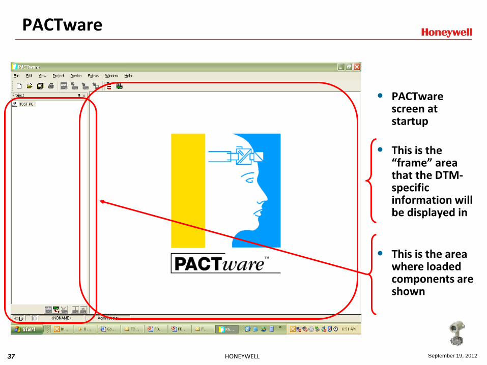
PACTware
• PACTware screen at startup
• This is the “frame” area that the DTM-specific information will be displayed in
• This is the area where loaded components are shown
38 HONEYWELL September 19, 2012
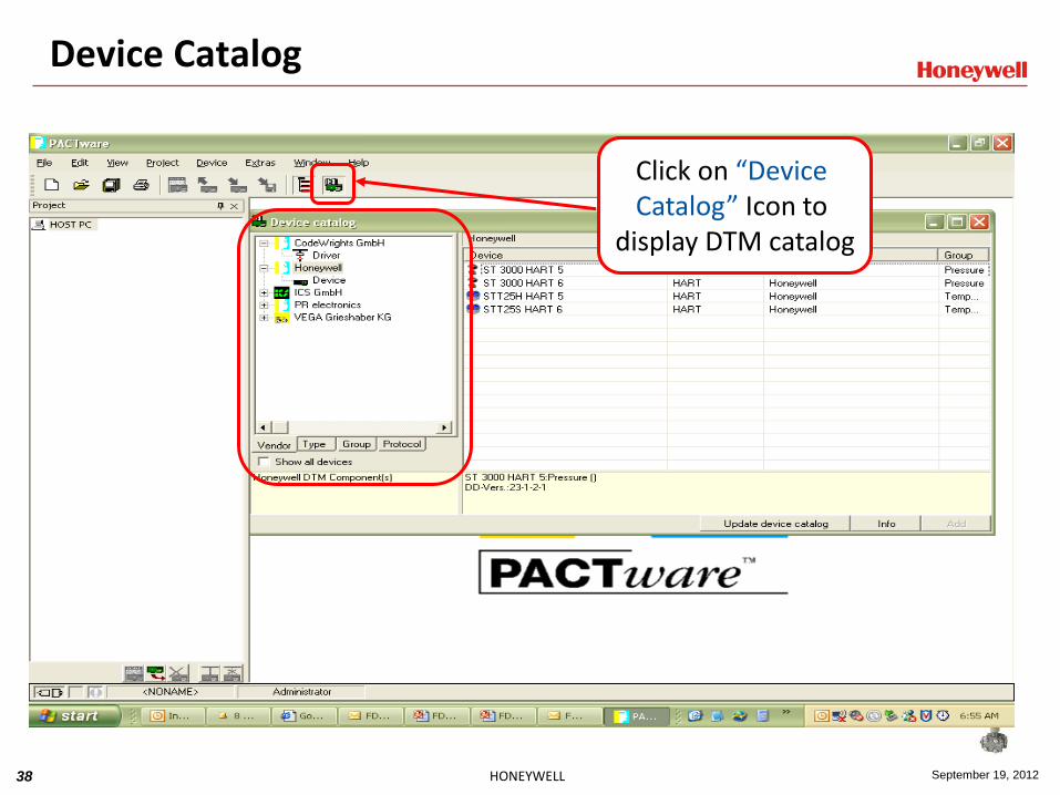
Device Catalog
Click on “Device Catalog” Icon to
display DTM catalog

39 HONEYWELL September 19, 2012
DTM Installation
• Installing a DTM is normally simple! - Download the Honeywell DTM zip file from the
website
- Extract files and run “Setup.exe”
• For DTMs from other vendors, please use the instructions provided from their respective web-sites for downloading and installation.
40 HONEYWELL September 19, 2012
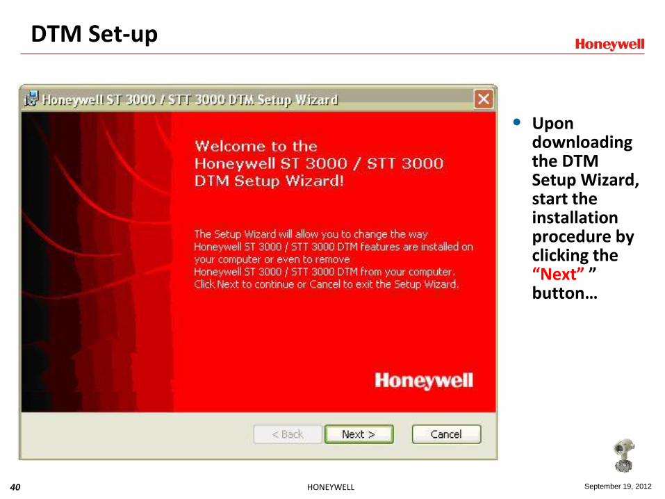
DTM Set-up
• Upon downloading the DTM Setup Wizard, start the installation procedure by clicking the “Next” ” button…
41 HONEYWELL September 19, 2012
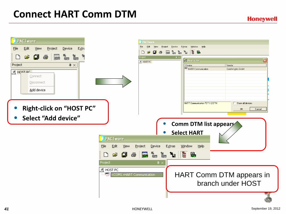
Connect HART Comm DTM
• Right-click on “HOST PC”
• Select “Add device” • Comm DTM list appears
• Select HART
• Click OK
HART Comm DTM appears in
branch under HOST
42 HONEYWELL September 19, 2012
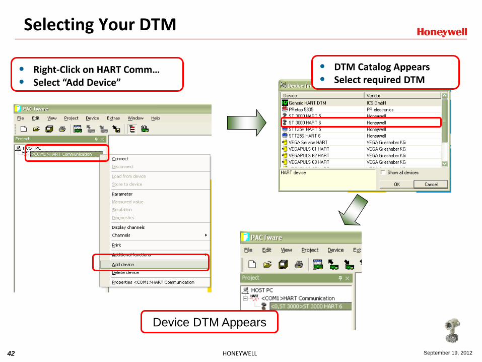
Selecting Your DTM
• Right-Click on HART Comm… • Select “Add Device”
• DTM Catalog Appears • Select required DTM
Device DTM Appears

43 HONEYWELL September 19, 2012
Connect Device
• Right-Click on “Device” • Select “Connect”
• “#” sign now indicates you are “Connected”.
44 HONEYWELL September 19, 2012
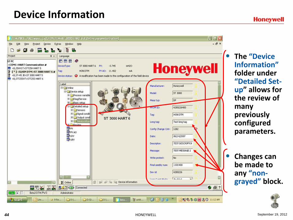
Device Information
• The “Device Information” folder under “Detailed Set-up” allows for the review of many previously configured parameters.
• Changes can be made to any “non-grayed” block.

45 HONEYWELL September 19, 2012
Device Set-up
• The “Device Set-up” folder has sub-set folders grouped to easily manage the device’s configuration process.
• Each folder displays information grouped together for ease-of-use.
46 HONEYWELL September 19, 2012
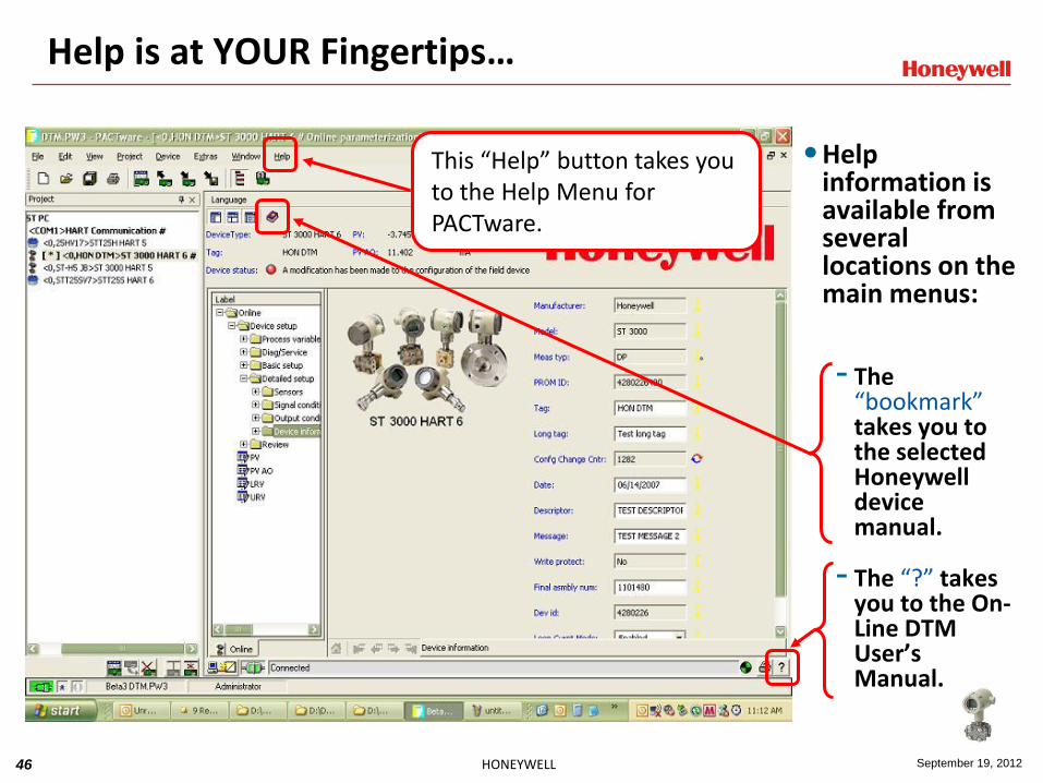
Help is at YOUR Fingertips…
•Help information is available from several locations on the main menus:
- The “bookmark” takes you to the selected Honeywell device manual.
- The “?” takes you to the On-Line DTM User’s Manual.
This “Help” button takes you to the Help Menu for PACTware.
47 HONEYWELL September 19, 2012
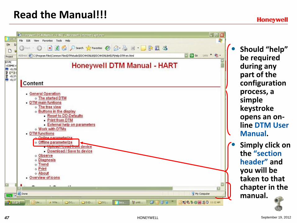
Read the Manual!!!
• Should “help” be required during any part of the configuration process, a simple keystroke opens an on-line DTM User Manual.
• Simply click on the “section header” and you will be taken to that chapter in the manual.

48 HONEYWELL September 19, 2012
Status Indication Made Easy!
• Under the “Diagnosis” folder sits several sub-folders that allow the user to view the various device status pages.
• Check marks indicate the presence of a fault or any change to the configuration that has been made.

49 HONEYWELL September 19, 2012
In a nutshell…
• The use of a DTM application allows for the complete configuration of the selected instrument.
• It requires no other interface software or device (such as a hand-held communicator) in order to configure or diagnose an instrument.
• Any certified “frame application” can configure any vendor’s instrument by using that vendor’s DTM software.
• Simply select the correct vendor’s DTM and establish contact with the device and you are ready to go.

50 HONEYWELL September 19, 2012
FDT – DTM and eDDL Topics
What is the problem/need?
EDDL
FDT/DTM
FDI
51 HONEYWELL September 19, 2012
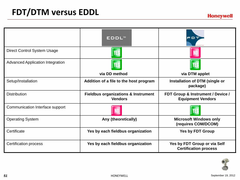
FDT
Direct Control System Usage
Advanced Application Integration
via DD method
via DTM applet
Setup/Installation Addition of a file to the host program Installation of DTM (single or
package)
Distribution Fieldbus organizations & Instrument
Vendors
FDT Group & Instrument / Device /
Equipment Vendors
Communication Interface support
Operating System Any (theoretically) Microsoft Windows only
(requires COM/DCOM)
Certificate Yes by each fieldbus organization Yes by FDT Group
Certification process Yes by each fieldbus organization Yes by FDT Group or via Self
Certification process
FDT/DTM versus EDDL

52 HONEYWELL September 19, 2012
FDT
Protocols HART, FF, Profibus, OPC Practically Any (FF, HART, Profibus-
DP/PA, Interbus, AS-I, DeviceNet,
ControlNet, and more to follow)
HMI Visualization By Control System Supplier By Device Vendor
Dependency between Control System
and its Operating System
International Standard IEC 61804-3
ANSI/ISA standard approval pending
Influence on system stability
No executable code
DTM is ActiveX object
Can be used in a handheld
FDT/DTM versus EDDL
53 HONEYWELL September 19, 2012
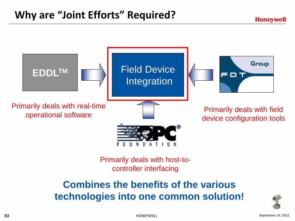
Why are “Joint Efforts” Required?
Field Device
Integration EDDLTM
Combines the benefits of the various
technologies into one common solution!
Primarily deals with host-to-
controller interfacing
Primarily deals with field
device configuration tools
Primarily deals with real-time
operational software

54 HONEYWELL September 19, 2012
Common Tools
Project
EDDL
Phase 1
Project
EDDL
Phase 2
Project
FDI Project
FDI Cooperation
LLC
’03 ’04 ’05 ’06 ’07 ’08 ’09 ’10 ’11 ’12 ‘13
History of Cooperation Projects

55 HONEYWELL September 19, 2012
Field Device Integration

56 HONEYWELL September 19, 2012
Device
Definition User Interface
Description User Interface
Plug-in Business Logic
Using
IEC 61804-3 EDDL
Based on
IEC 62453 FDT
Device Package
Using
IEC 62541 OPC UA
FDI Device Package Standard
Attachments
e.g
Datasheets,
Manuals,
Certificates

57 HONEYWELL September 19, 2012
www.honeywell.com


