FE Simulation of Honeycomb Core Sandwich Panels for the Body Lightweight honeycomb sandwich structures have been increasingly employed in the automotive industry: from parcel-shelf to load-floor applications. There can be an infinite variety of possible solutions adopted for these parts depending on the choice of the core geometries and of the materi- als. In the design phase an efficient prediction tool is needed – Rieter has developed a mathematical model based on a multi-scale asymptotic technique. DEVELOPMENT Lightweight Design 26 ATZ 01I2008 Volume 110
Transcript
FE Simulation of Honeycomb Core Sandwich Panels for the BodyLightweight honeycomb sandwich structures have been increasingly employed in the automotive industry: from parcel-shelf to load-floor applications. There can be an infinite variety of possible solutions adopted for these parts depending on the choice of the core geometries and of the materi-als. In the design phase an efficient prediction tool is needed – Rieter has developed a mathematical model based on a multi-scale asymptotic technique.
Development Lightweight Design
26 AtZ 01I2008 volume 110
1 Introduction
Two main factors drive the progressive introduction of sandwich structures in the automotive industry: value of stiff-ness to weight ratio and, not surprising-ly, material and processing cost. The problem of weight reduction, common to all forms of transportation for reasons of fuel economy and driving perform-ance, demands solutions that maximize structural stiffness with less material. In the automotive industry, sandwiches have already made their first steps in re-placing conventional solutions for both non-structural components – such as parcel shelf or load floor panels – in most of the automotive market, and with structural function in high performance sports models.
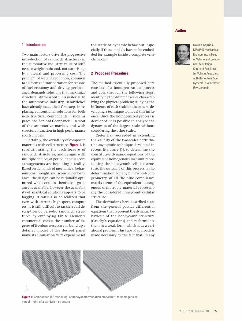
Certainly, the versatility of composite materials with cell structure, Figure 1, is revolutionizing the architecture of sandwich structures, and designs with multiple choices of periodic spatial core arrangements are becoming a reality. Based on demands of mechanical behav-iour, cost, weight and acoustic perform-ance, the design can be rationally opti-mized when certain theoretical guid-ance is available; however the availabil-ity of analytical solutions appears to be lagging. It must also be realized that even with current high-speed comput-ers, it is still difficult to tackle a full de-scription of periodic sandwich struc-tures by employing Finite Elements commercial codes: the number of de-grees of freedom necessary to build up a detailed model of the desired panel make its simulation very expensive (of
the static or dynamic behaviour) espe-cially if these models have to be embed-ded for example inside a complete vehi-cle model.
2 Proposed Procedure
The method essentially proposed here consists of a homogenization process and goes through the following steps: identifying the different scales character-izing the physical problem; studying the influence of each scale on the others; de-veloping a technique to model this influ-ence. Once the homogenized process is developed, it is possible to analyze the dynamics of the largest scale without considering the other scales.
Rieter has succeeded in extending the validity of the two-scales perturba-tion asymptotic technique, developed in recent literature [1], to determine the constitutive dynamic equations of the equivalent homogenous medium repre-senting the honeycomb cellular struc-ture: the outcome of this process is the determination, for any honeycomb core geometry, of all the nine compliance matrix terms of the equivalent homog-enous orthotropic material represent-ing the considered honeycomb cellular structure.
The derivations here described start from the general partial differential equations that represent the dynamic be-haviour of the honeycomb structure (Cauchy’s equations) and re-formulate them in a weak form, which is as a vari-ational problem. This type of approach is made necessary by the fact that, in any
Author
Davide Caprioli, mSc phD mechanical engineering, is Head of vehicle and Compo-nent Simulation, Centre of excellence for vehicle Acoustics, at Rieter Automotive Systems in Winterthur (Switzerland).
Figure 1: Comparison (FE modelling) of honeycomb validation model (left) to homogenized model (right) of a sandwich structure
AtZ 01I2008 volume 110 27
honeycomb structure, the transition from the cell wall to the air around it de-termines discontinuities in the local den-sity and in the local elasticity tensor of the honeycomb structure. Therefore one considers a 3D-periodic body occupying a bounded region Ω in the Euclidean R3 space, defined by coordinates x1, x2 und x3. Assuming a linear behaviour, the equations that describe the dynamics of the body can be written as follows:
ρ Dvi ___ Dt – ∂ ___ ∂xj
( Cijkl ∂ul
___ ∂xk ) = ρfi in Ω Eq. (1)
Here u is the displacement field, v is the velocity field, D __ Dt is the material deriva-tive, ρ is the density, Cijkl are the terms of the elastic tensor, and fi are the terms relative to the mass loads. For a linear elastic body the tensor Cijkl must be posi-tive definite and must satisfy the follow-ing symmetry conditions:
Cijkl = Cjikl = Cijlk = Cklij Eq. (2)
For any periodic structure the elasticity tensor Cijkl and the density ρ will be peri-odic functions of the spatial coordinates.
As a consequence of this, it will be possible to isolate a unit cell of the global structure, intended as the region that covers a single spatial period of the elas-ticity tensor and of the density. By defin-ing, on this domain, local coordinates (micro-scale coordinates) (y1, y2, y3) one has u = u (x1, x2, x3, y1, y2, y3, t), v = v (x1, x2, x3, y1, y2, y3, t) and C = C (y1, y2, y3). The micro-scale coordinates are able to de-scribe the small oscillating perturbations of the solution, while the macro-scale co-ordinates are able to describe the average spatial trend of the solution.
Using the periodicity of the perturba-tions and the Green theorem, two of the endless variational equations are extract-ed: the first represents the micro-scale
equation while the second is the macro-scale equation.The macro-scale equation provides the solution of the equivalent material iden-tification, since it gives the definition of the averaged density and stiffness tensor, which are the equivalent properties needed to be identified. Indeed analyz-ing the expression of the average stiff-ness tensor, it can be seen that together with known properties such as the vol-ume of the 3D periodic cell geometry, and the stiffness tensor of the material constituting the honeycomb, the expres-sion presents a third order tensor χ q
kl , which is unknown.
The identification of this unknown micro-scale tensor comes from the varia-tional equation system expressing the micro-scale problem. This equation sys-tem can be solved by means of numerical computation on the cell domain. And thanks to the symmetry of the equiva-lent elastic tensor only the solution of ten terms of the unknown micro-scale tensor χ q
kl (y1, y2, y3) have to be performed. Once all the χ q
kl have been obtained by numerical solution on the cell domain, for the computation of the equivalent elastic tensor we can directly apply the macro-scale dynamic equation already obtained from the endless variational equations deriving from Eq. (1).
3 Numerical/Numerical Validation
To confirm the results of the proposed formulation, we compared, for the most common honeycomb core configura-tions, a detailed FE model versus our ho-mogenized approach. With this type of validation, since no problem regarding the material and geometry uncertainty arises, between the compared models, it is possible to better appreciate the accu-racy of the proposed approach. Here the
results obtained for a typical honeycomb core structure with hexagonal cell (with 4 mm side length and 8 mm width) are considered. In particular considering a honeycomb sandwich plate (1000 mm × 900 mm) with 1 mm aluminium skins, and 2 mm core height made with poly-propylene.
The validation of the multi-scale tech-nique is carried out employing the com-mercial FE code M.S.C. Nastran. The vali-dation process consists in the compari-son between the dynamic behaviours of two different finite element models of a sandwich structure with honeycomb core, Figure 1:– the validation model, where the thin-
walled core of the selected honeycomb is described with a fine mesh made of linear plate elements (CQUAD4), to which the polypropylene material properties attributed. This model end-ed up having nearly 218.000 nodes.
– the homogenized model, where the volume bounding the core layer has been meshed with 3D elements. This involved a much lower modelling ef-fort compared to the validation mod-el, leading to an FE description with only approximately 5500 nodes. To these brick elements (CHEXA) the or-thotropic material (MAT 9) behaviour with the equivalent homogeneous core properties have been applied.
Both the FE models present two skins, which are simulated via isotropic linear plate elements (CQUAD4). A first com-parison between the two mentioned nu-merical models was performed with re-spect to a static solution, loading the plate with a uniform load of 10 N on a central square area, and with simple support condition on two opposite pan-el sides, on the skin opposite to the load. The solution of the validation model took 19 min while the solution of the homogenized model took approximate-
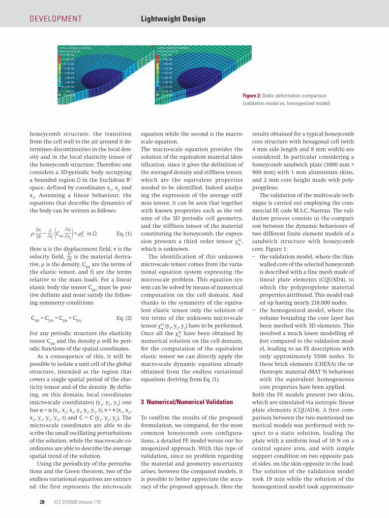
Figure 2: Static deformation comparison (validation model vs. homogenized model)
Development Lightweight Design
AtZ 01I2008 volume 11028
ly 1.5 min. The results show that not only is the deformation profile of the full model reproduced correctly by the homogenous one, but the local defor-mation is also correctly represented leading to a maximum 3.5 % difference in the displacement field of these two models, Figure 2.
A further comparison between the two models involved the forced response of the sandwich panel, when exciting the sandwich panel, in free-free condi-tion, on one point with a force normal to the skin surface. The average mobility frequency response function is per-
formed over the simulated FRFs, by sum-ming up the contributions of all the nodes belonging to the skin opposite to the one where the loads are applied. Sev-eral excitation points have been consid-ered. Figure 3 shows the results where one of them is applied.
Also in this behaviour comparison, despite the difference for both the mod-elling effort and solution time (approxi-mately 6 h for the validation model and 43 min for the homogenized model), the proposed homogenized model is able to provide a response, which is pretty simi-lar to the one of the validation model.
4 Numerical/Experimental Validation
Similar results as mentioned in Chapter 3 have been obtained with numerical vali-dation of other core shapes, and with numerical and experimental validation of flat sandwich plates [2]. Here for brev-ity the application of the proposed ho-mogenization method to the simulation of a load floor panel in the trunk will be reported, Figure 4.
This load floor is composed of sand-wich carrier material, named RHOC (Rieter Honeycomb), which is made up of the following starting layers: two skin layers made out of EAC material (glass fibre based material), a polypropylene tubular honeycomb core (17 mm thick-ness), and on top a non woven carpet. In the production process, this starting pileup undergoes a hot moulding proc-ess, which delivers the final shape: as a result of it the part presents several are-as where the core has been squeezed be-tween the skins, but also many local skin curvatures, so that the component presents a non uniform thickness. Con-cerning the modelling of the core, it has been meshed with 3D linear tetra ele-ments in order to adapt to the skin ge-ometry: this has lead to an FE model having 17.000 nodes. The model was di-vided into two parts: one zone where the thickness variation could be consid-ered negligible, and a region where a high compression ratio of the core was evident.
Both these parts inherited the stiff-ness equivalent macro characteristics, using the proposed methodology; the only difference was on the equivalent density given to these parts. For the nu-merical/experimental validation, com-parison the forced response computed with the FE model just described, with the spectra on two load floor samples are measured. These were suspended with rubber bands on the upper cor-ners, acquiring the vibrations on one floor skin by means of a laser scanner on 221 points, Figure 5.
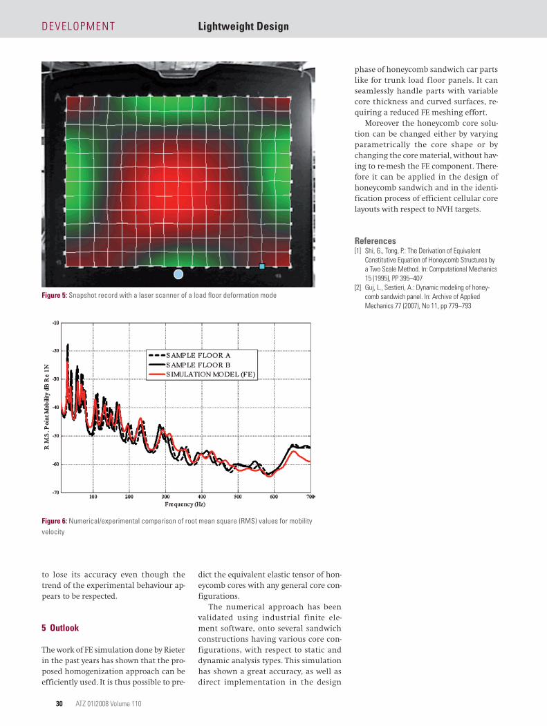
Figure 6 shows how well the proposed modelling can correlate to the measure-ments. Despite the high geometrical and material complexity, the numerical mod-el can find a pretty good agreement with measurements up to nearly 500/600 Hz. Only at higher frequencies does it seem
Figure 3: Root mean square (RMS) of mobility comparison (validation model vs. homogenized model)
Figure 4: Detail of a trunk load floor section with honeycomb cores
AtZ 01I2008 volume 110 29
to lose its accuracy even though the trend of the experimental behaviour ap-pears to be respected.
5 Outlook
The work of FE simulation done by Rieter in the past years has shown that the pro-posed homogenization approach can be efficiently used. It is thus possible to pre-
dict the equivalent elastic tensor of hon-eycomb cores with any general core con-figurations.
The numerical approach has been validated using industrial finite ele-ment software, onto several sandwich constructions having various core con-figurations, with respect to static and dynamic analysis types. This simulation has shown a great accuracy, as well as direct implementation in the design
phase of honeycomb sandwich car parts like for trunk load floor panels. It can seamlessly handle parts with variable core thickness and curved surfaces, re-quiring a reduced FE meshing effort.
Moreover the honeycomb core solu-tion can be changed either by varying parametrically the core shape or by changing the core material, without hav-ing to re-mesh the FE component. There-fore it can be applied in the design of honeycomb sandwich and in the identi-fication process of efficient cellular core layouts with respect to NVH targets.
References[1] Shi, G., tong, p.: the Derivation of equivalent
Constitutive equation of Honeycomb Structures by a two Scale method. In: Computational mechanics 15 (1995), pp 395–407
[2] Guj, l., Sestieri, A.: Dynamic modeling of honey-comb sandwich panel. In: Archive of Applied mechanics 77 (2007), no 11, pp 779–793
Figure 6: Numerical/experimental comparison of root mean square (RMS) values for mobility velocity
Figure 5: Snapshot record with a laser scanner of a load floor deformation mode