III European Conference on Computational Mechanics Solids, Structures and Coupled Problems in Engineering C.A. Mota Soares et.al. (eds.) Lisbon, Portugal, 5–8 June 2006 FE-TOOL CODAC FOR AN EFFICIENT SIMULATION OF LOW-VELOCITY IMPACTS ON COMPOSITE SANDWICH STRUCTURES Luise K ¨ arger, Jens Baaran, Jan Teßmer Institution DLR, Institute of Composite Structures and Adaptive Systems Lilienthalplatz 7, 38108 Braunschweig, Germany [email protected], [email protected], [email protected]Keywords: Impact Simulation, Impact Damage, Sandwich Structures, Damage Mechanics, Finite Element Analysis. Abstract. The finite element based damage tolerance tool, CODAC, has been developed for efficiently simulating the damage resistance of sandwich structures subjected to low-velocity impacts. The considered double shell structures consist of two thin composite face sheets sep- arated by a lightweight core. While sandwich structures are very weight efficient and provide integrated damping and insulation, impact damage in sandwich structures can provoke a signif- icant strength and stability reduction. Therefore, the objective of CODAC is to develop method- ologies which reliably simulate impact events and accurately predict impact damage sizes. Since frequent design loops require a quick analysis, efficient deformation and failure models are needed. To achieve a rapid and accurate stress analysis, a recently developed three-layered finite shell element is used. Failure analysis is based on a progressive damage mechanics ap- proach: Damage initiation is detected by stress-based failure criteria. Material resistance is reduced by appropriate degradation models. An experimental impact test program on honeycomb sandwich panels is used to validate the impact simulation of the FE-tool CODAC. Force-time histories and damage sizes are examined, and the influence of distinct failure models on the impact response is analyzed. Comparisons between impact tests and simulations showed that CODAC is capable of accurately and rapidly simulating impact events, which induce barely visible damage. 1
Transcript
III European Conference on Computational MechanicsSolids, Structures and Coupled Problems in Engineering
C.A. Mota Soares et.al. (eds.)Lisbon, Portugal, 5–8 June 2006
FE-TOOL CODAC FOR AN EFFICIENT SIMULATION OFLOW-VELOCITY IMPACTS ON COMPOSITE SANDWICH
STRUCTURES
Luise Karger, Jens Baaran, Jan Teßmer
InstitutionDLR, Institute of Composite Structures and Adaptive Systems
Abstract. The finite element based damage tolerance tool, CODAC, has been developed forefficiently simulating the damage resistance of sandwich structures subjected to low-velocityimpacts. The considered double shell structures consist of two thin composite face sheets sep-arated by a lightweight core. While sandwich structures are very weight efficient and provideintegrated damping and insulation, impact damage in sandwich structures can provoke a signif-icant strength and stability reduction. Therefore, the objective of CODAC is to develop method-ologies which reliably simulate impact events and accurately predict impact damage sizes.
Since frequent design loops require a quick analysis, efficient deformation and failure modelsare needed. To achieve a rapid and accurate stress analysis, a recently developed three-layeredfinite shell element is used. Failure analysis is based on a progressive damage mechanics ap-proach: Damage initiation is detected by stress-based failure criteria. Material resistance isreduced by appropriate degradation models.
An experimental impact test program on honeycomb sandwich panels is used to validate theimpact simulation of the FE-tool CODAC. Force-time histories and damage sizes are examined,and the influence of distinct failure models on the impact response is analyzed. Comparisonsbetween impact tests and simulations showed that CODAC is capable of accurately and rapidlysimulating impact events, which induce barely visible damage.
1
Luise Karger, Jens Baaran, Jan Teßmer
1 INTRODUCTION
Aircraft design calls for weight efficient shell constructions. Sandwich structures satisfy thisdemand by the combination of two thin, stiff face sheets and an intermediate lightweight core.Furthermore, the outer face sheet can act as an impact detector while the core provides dampingand insulation. Thus, sandwich structures are increasingly aspired for application as fuselageand wing panels. However, impact damage in sandwich structures can provoke a significantstrength and stability reduction. Therefore, the number of publications on impact behaviourof sandwich structures has recently increased. A number of experimental studies (e. g. [1]-[4]) were conducted to observe impact damage progression for different core and face sheetmaterials. The link between different stages of damage and changes in force-time historieswas studied. It could be shown that invisible core crushing is the first damage mode whichoccurs during impact, it slightly lowers the slope of the force-time history. At higher energies,the contact force may reach a peak value, which was found to be an indicator for face sheetcracking.
To predict the impact response and the amount of impact damage, several simulation method-ologies have been developed, [5]-[14]. Some of them are based on a simple analytical approach,which predicts damage initiation but does not describe damage progression, e.g. [5]-[8]. Fur-thermore, analytical models are restricted to special plate boundaries. By contrast, finite elementsimulations are flexible in terms of boundary conditions. Moreover, they account for progres-sive damage and non-linear material behaviour. Therefore, finite element approaches generallyattain a more accurate description of the impact response. However, very fine FE models with anumber of elements in thickness direction (e. g. [9]-[11]) require a large computational effort.On the other hand, much coarser models ([12]-[14]), may allow a more efficient simulation, butusually suffer losses in accuracy. For further information on publications about impact simula-tion see [15].
This paper presents the methodology of the finite element tool CODAC, whose main ob-jective is a high efficiency in simulating impacts on sandwich structures, chapter 2. In section2.1 a three-layered finite shell element is introduced to model the deformation and stress be-haviour of sandwich structures. Instruments of the transient impact analysis are explained insection 2.2. The main focus of this paper is the validation of impact simulation results, chapter3, where an impact test program is used for comparison, section 3.1. Simulation results in termsof force-time histories and core damage sizes are presented and evaluated for different degrada-tion models in sections 3.2 to 3.4. Finally, information is given about the computational effortof impact simulations with CODAC.
2 DAMAGE TOLERANCE TOOL CODAC
The DLR in-house tool CODAC (Composite Damage Tolerance Analysis Code) is a fastfinite element tool, which is used in the design process to efficiently simulate the low-velocityimpact behaviour of composite panels and to compute the residual strength, [16], [17]. CODACwas originally designed for monolithic CFRP structures. To meet the increasing interest of theaircraft inductry in double shell structures, it is presently enhanced for sandwich panels.
2.1 Finite sandwich elements
To be used in the design process, the impact simulation methodologies need to be fast andat the same time sufficiently accurate. Since a reliable deformation and stress prediction is anessential precondition for an accurate failure analysis, a suitable finite element is needed, which
2
Luise Karger, Jens Baaran, Jan Teßmer
predicts in-plane stresses as well as transverse shear and normal stresses precisely enough. Con-sequently, a suitable finite element should be capable of efficiently modelling the characteristicdeformation behaviour of double shell structures: Large shear strains may occur in the soft core,whereas the cross-sections of the skins remain almost orthogonal to the in-plane direction. Byconsidering and evaluating a couple of finite element concepts, two new sandwich elementshave been developed.
The first sandwich element, called S89 and proposed by Karger et al. [18], is a three-layeredshell element, which is based on a plane stress assumption. It is described by eight nodes andserendipity form functions. The displacement approach in thickness direction is developed byusing the first-order shear deformation theory (FSDT) for each of the three layers (core andtwo skins), coupled by displacement continuity conditions at the interfaces. Consequently, eachnode incloses nine degrees of freedom. In order to improve transverse stiffness and stresses, anenhancement of the Extended 2D Method by Rolfes and Rohwer [19] was developed.
It has turned out, however, that under concentrated out-of-plane loads element S89 lacksappropriate accuracy of stress results. Therefore, an improved finite element formulation wasdeveloped by Wetzel et al. [20], which accounts for the full 3D sress state. Due to its 15 degreesof freedom per node, this element was called S815. Analogous to the former element S89,it is an isoparametric eight-node shell element and the in-plane displacements are describedby a layer-wise linear approach in thickness direction. As a distinction to element S89 thecompressibility in thickness direction is included in the kinematical approach. This additionis made to better account for the local transverse strains due to concentrated impact loading inconnection with a soft core material. In order to avoid Poisson thickness locking, a parabolicdistribution was chosen for the out-of-plane displacement. Hence, the kinematics of each of thethree layersL is described by uL(x, y, z)
vL(x, y, z)wL(x, y, z)
=
u0L(x, y)v0
L(x, y)w0
L(x, y)
+ zL
ψxL(x, y)ψyL(x, y)ψzL(x, y)
+ (zL)2
00
ϕzL(x, y)
, (1)
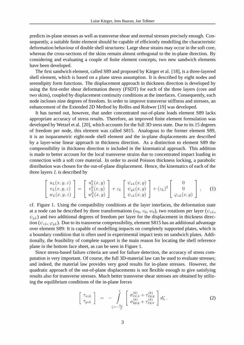
cf. Figure 1. Using the compatibility conditions at the layer interfaces, the deformation stateat a node can be described by three transformations (u0, v0, w0), two rotations per layer (ψxL,ψyL) and two additional degrees of freedom per layer for the displacement in thickness direc-tion (ψzL,ϕyL). Due to its transverse compressibility, element S815 has an additional advantageover element S89: It is capable of modelling impacts on completely supported plates, which isa boundary condition that is often used in experimental impact tests on sandwich plates. Addi-tionally, the feasibility of complete support is the main reason for locating the shell referenceplane in the bottom face sheet, as can be seen in Figure 1.
Since stress-based failure criteria are used for failure detection, the accuracy of stress com-putation is very important. Of course, the full 3D-material law can be used to evaluate stresses;and indeed, the material law provides very good results for in-plane stresses. However, thequadratic approach of the out-of-plane displacements is not flexible enough to give satisfyingresults also for transverse stresses. Much better transverse shear stresses are obtained by utiliz-ing the equilibrium conditions of the in-plane forces[
τxzL
τyzL
]= −
z∫ζ=−h1
2
[σ
(k)xx,x + τ
(k)xy,y
σ(k)yy,y + τ
(k)xy,x
]dζ . (2)
3
Luise Karger, Jens Baaran, Jan Teßmer
3xψ
0 01u u=
03uz3
x
z
z2
z1
02u
02w
03w
2xψ
1xψ
h3
h2
h1/2h1/2
core
lowerface-sheet
upperface-sheet
0 01w w=
initial statedeformed state
Figure 1: Kinematic approach of element S815
In order to avoid the necessity of second derivatives of the shape function, the equilibriumequation is modified in a way that the transverse shear stresses can be described as a functionof the transverse shear forces,
This procedure builds on the above mentioned enhancement of the Extended 2D Method [19]for three-layered shell elements, which was proposed by Karger et al. [18].
The suchlike improved transverse shear stresses have the advantage of being linear in in-plane direction. Therefore, they can be differentiated and used to calculate transverse normalstresses by solving the equilibrium equation in thickness direction,
σzzL = −z∫
ζ=−h12
(τxz,x + τyz,y) dζ + qz0 , (4)
whereqz0 are the external loads in thickness direction, cf. Rolfes et al. [21]. Since here thesecond derivatives of the shape function are unavoidable, the transverse normal stresses areelement-wise constant in in-plane direction and, therefore, the optimal stress point is in theelement centre rather than in the four Gauß points.
Computational tests, where the analytical solution by Pagano [22], [23] was used for com-parison, have shown that the equilibrium method provides very good transverse stresses: Trans-verse shear stresses were always better than those from material law. For plates with smoothlydistributed loads, transverse normal stresses could also be improved. However, plates with con-centrated loads, like impacts, caused some more difficulties: Because of the extreme local stressconcentration, oscillations in the transverse normal stresses cannot be completely avoided, nei-ther by the equilibrium approach nor by the material law. In order to minimise these oscillations,on one hand, the impact force is modelled by a parabolically distributed surface load, whosearea grows consistenly with the Hertzian contact area. On the other hand, for stress-based fail-ure analysis a combination of both methods is used, which applies in each case the more critical
4
Luise Karger, Jens Baaran, Jan Teßmer
value of the two stress results. Therewith, the transverse normal stress computation also givereliable and conservative results.
2.2 FE-modelling and transient impact analysis
An impact simulation technique of sandwich structures, which makes use of the new sand-wich elements S89 and S815, was first published by Karger et al. [15]. Fig. 2 exemplifies thefinite element modelling used in CODAC for impact analysis. The impacted area is mesheda lot finer than the outer parts of the panel to be able to correctly predict incremental damagegrowth near the stress concentration while keeping the computational effort as low as possible.The Figure shows one of the meshes, which was used to simulate the impact tests introduced
Impactor, modelled by a point mass, applied as parabolically distributed load
sandwich panel, meshed with elements S815
Figure 2: FE-modelling for impact analysis.
in chapter 3. If the lay-up of the laminate is symmetric, it is sufficient to model a quarter ofthe panel. Furthermore, computational tests have shown that only a bounded inner region ofthe plate is affected by the impact load. Therefore, in the simulations of chapter 3 it was suffi-cient to model a smaller, quadratic part, shown by the zoom in Fig 2. It might appear that thesandwich plate is meshed rather coarsely. However, the here introduced mesh turned out to beprecise enough to achieve good results, as demonstrated in section 3.2.
The impactor is modelled by a point mass. The contact force between impactor and plateis distributed parabolically. The magnitude of the impact load as well as the expanse of theloaded area is calculated via the Hertzian contact law. For simulating the dynamic process,CODAC uses the implicit Newmark time integration scheme. Comparative studies have shownthat the explicit central difference method requires extremely small time steps to achieve stabil-ity. Therefore, implicit time integration was found to be more efficient for the demands of thedesign tool CODAC.
5
Luise Karger, Jens Baaran, Jan Teßmer
3 IMPACT SIMULATION RESULTS
3.1 Impact tests used for validation
The impact tests, which are used in the following to validate the impact simulation tech-niques, were conducted at the department ILR at Dresden University of Technology [24]. Testresults in the form of force-time histories, damage photographs and ultrasonic scans were pro-vided by courtesy of ILR Dresden. Figure 3 shows the impact test facilities of ILR. The sand-
Figure 3: Impact facilities at ILR Dresden.
wich panels were completely supported and impacted with a steel hemisphere (� 25.4mm,1.10kg) and energies between 1J and 15J. The panels consisted of NOMEX honeycomb 4.8-48core of 28mm thickness and Cytec 977-2/HTA face sheets. Since the top face sheet shall act asimpact detector, while the main inplane loads are carried by the bottom face sheet, the sandwichis asymmetric and the impacted face sheet is very thin with three plies and a nominal thicknessof only 0.633mm.
Force-time and displacement-time histories (Fig. 4) are important experimental results forimpact tool validation. Whereas the force-time curve of the 1J impact is almost sine-like, at the8J and 15J impacts a sharp bend occurs at about 1kN, which coincides with an indentation ofabout 3mm. This sharp bend indicates a massive damage, which can be identified as the beginof face sheet cracking. Another, but slight bend can be seen in all force-time curves at a verylow energy-level. This indicates a stiffness reduction, which is caused by core crushing.
A further indication for failure behaviour during impact is given by damage images. InFigures 5 and 6 the middle, ultrasonic images show the condition of the top face sheet, whereblack areas are actual face sheet damages and the grey areas show the interface between skinand core. At 1J impact, where a contact force of 1kN is not reached, the top face sheet does notexperience visible damage (Fig. 5). On the other hand, at 8J the skin is considerably affected(Fig. 6). Contrary to the first ultrasonic scan, the right ultrasonic scan indicates core failure,since here the complete sandwich, inclusive core, is scanned. It can be seen that considerablecore failure occurs already at 1J.
3.2 Impact simulation without failure analysis
To validate the pure deformation analysis during impact, which is performed by the newsandwich elements S815, the Hertzian contact law and the Newmark time stepping scheme
6
Luise Karger, Jens Baaran, Jan Teßmer
0
0.4
0.8
1.2
0 2 4 6 8 10t / ms
F / k
N
8J
15J1J
-20
-16
-12
-8
-4
0
w /
mm
8J
15J
1J
Figure 4: Force-time and displacement-time histories from impact tests at ILR Dresden.
Figure 5: Damage images from ILR Dresden: photograph and US scans (echoes of top and bottom skin), 1J impact.
Figure 6: Damage images from ILR Dresden: photograph and US scans (echoes of top and bottom skin), 8J impact.
(section 2.2), the simulation is first carried out without any material degradation. Analysingthe impact response without degradation means that all stiffness components of the sandwich
7
Luise Karger, Jens Baaran, Jan Teßmer
plate remain constant during the whole impact analysis. Fig. 7 shows the force-time historiesfor a 1J impact. The two red experimental results show only little scatter. The four FE analysiscurves demonstrate differences for different meshing and different loading: For the blue curvesthe load is modelled by a single nodal load, for the green curves the load is parabolically dis-tributed. It can be seen that applying a single nodal load results in a mesh dependent response,i.e. the modelled plate is increasingly compliant for finer meshes (curve of the mesh with 38elements is lower than the curve of the mesh with 14 elements). On the other hand, the twogreen curves overlap almost completely and indicate mesh independent results. Furthermore,the initial slopes, which represent the stiffness of the intact material, agree with the slopes ofthe experimental curves very well. Therefore, in all following simulations, the impact load isparabolically distributed and the coarser mesh is used, since it is precise enough to achieve meshindependent results.
0.0
0.4
0.8
1.2
0 1 2 3 4 5 6t / ms
F / k
N
14 elem. & 38 elem., parab. load
14 elem., single load
38 elem., single load
Experiment 1J
Figure 7: Without degradation: Force-time histories of a 1J impact.
The computed curves leave the experimental curves already at a small contact force of about0.25kN. At this point, the core starts to crush and, consequently, the stiffness of the plate de-creases. In order to correctly describe the further impact response, core failure needs to bedetected and subsequently core material needs to be degraded.
3.3 Impact simulation including a core failure model
The core fails due to combined shear and compression. Consequently, for detecting failureinitiation, the failure criterion by Besant et al. [13] is used, which includes both, transversenormal and transverse shear stresses,(
σzz
σcu
)n
+
(τxz
τlu
)n
+
(τyz
τtu
)n
≥ 1 . (5)
In Besant’s combined shear-compression-tests, an exponent ofn = 1.5 produced the best fitwith experimental results. Therefore, in the impact analysis of CODAC,n = 1.5 is defined asdefault value. However, numerical test runs with exponents between 1.0 and 2.0 did not show aremarkable influence on the force-time history or on final impact damage.
Fig. 8 shows force-time histories of a 1J impact. For two computed curves a core failureis taken into account. In both cases, onset of core damage is correctly detected, which demon-strates the capability of the failure criterion.
8
Luise Karger, Jens Baaran, Jan Teßmer
0
0.4
0.8
1.2
0 1 2 3 4 5 6t / ms
F / k
N
total core degradation
Experiments, 1J
proposed core degradation model
no degradation
Figure 8: With core degradation: Force-time histories of a 1J impact.
If the material of all damaged core regions is totally degraded, i.e. all stiffness componentsare set to a value close to zero, the green curve in Fig. 8 arises. Evidently, such atotal coredegradationmodels the damaged core too soft and results in an underestimation of the contactforce. Furthermore, this computation heavily overestimates the damaged area: In the secondpicture of Fig. 9 the area with blue crosses, which shows the computed damage area, is muchlarger than the red circle, which displays the border line of the experimental damage area.
no degradation
CODAC
Test
total coredegradation
proposed coredegradation model
Figure 9: With core degradation: Core damage of a 1J impact.
Consequently, a more sophisticated degradation model is needed, which does not just treatthe damaged core as non-existing but really looks at its material behaviour. Therefore, thestress-strain-path of the core material is investigated and, subsequently, implemented into thecore failure model. Exemplarily, Fig. 10 shows force-displacement curves of compression tests,which were carried out at ILR Dresden to characterise the material behaviour of the studied hon-eycomb core. It can be seen that after reaching ultimate strength, the stresses do not drop tozero as assumed before, but the core crushes at a certain stress level. Due to this remainingcrush strength, the damaged core absorbes energy, which needs to be regarded in the Principleof Virtual Work. By representing this additional energy in the finite element stiffness relationbetween nodal displacements and nodal forces, an additional inner nodal force arises, whichoperates in the opposite direction of the outer contact force and, therewith, provides a consid-erable residual resistance of the damaged core. Furthermore, after reaching the crush strengthlevel, the stresses slightly increase. Therefore, the corresponding stiffness component must notbe set to zero, but reduced according to the reduced slope of the material’s stress-strain path.Summarising, the failure model for core compression, which arises by taking both, the residualstrength and residual stiffness into account, is the step-wise linear function shown by the blackcurve in Fig. 10.
9
Luise Karger, Jens Baaran, Jan Teßmer
0
1000
2000
3000
4000
0 0.5 1 1.5 2 2.5 3 3.5 4w in [mm]
F in
[N]
core failure model (pure compression)
compression tests, ILR Dresden
Figure 10: Force-displacement curve of core compression.
At shear loading, a force-displacement relation similar to the one in Fig. 10 can be observed.Since the true failure behaviour of the core is a combination of transverse compression andtransverse shear, an average remaining resistance has to be assumed. Under consideration oftypical strain values and the associated amount of absorbed energy, crush strength and crushstiffness values can be approximated (see Table 1 for the values used in this study). In orderto avoid numerical instability due to an ill-conditioned finite element system of equations, theremaining shear resistance is modeled by an average crush stiffness combined with zero crushstrength. For more detailed information on CODAC’s core damage modelling see [15].
Table 1: Factors for crush strength and crush stiffness of damaged core
Compression Shear xz Shear yz
(i = 3) (i = 5) (i = 4)σi,crush/σi,ult 0.3 0 0Cii,crush/Cii 0.02 0.3 0.4
By applying the proposed core degradation model during the impact simulation, the experi-mental results are approximated much better than by using the above introduced total degrada-tion model, cf. blue curve in Fig. 8 and right picture in Fig. 9. The force-time curve is displayedhere only up to maximum deflection, because the unloading stress-strain-path of the plasticallydeforming core is not implemented yet. It can be concluded that for impacts without visibleface sheet damage, the force-time history curves are very well described and a quite accuratedamage area is computed.
However, for an increasing impact energy, contact forces larger than 1kN and remarkableskin damages are expected. Fig. 11 shows the force-time histories of an 8J impact: In accor-dance with the 1J impact, the initial stiffness is well approximated and the first core damage atabout 0.4kN is correctly detected. Furthermore, by considering the proposed core degradationmodel, the remaining stiffness of the damaged core is accurately modeled.
However, at about 1.0kN the upper face sheet experiences a substantial damage. Thus, facesheet degradation needs to be considered to be able to keep on following the experimentalforce-time curve.
3.4 Failure and indentation behaviour of face sheets
In CODAC, several approved stress-based failure criteria and stiffness degradation modelsfor fibre breakage, matrix cracking and delamination are available. Parametric studies were
10
Luise Karger, Jens Baaran, Jan Teßmer
0
0.5
1
1.5
2
2.5
0 1 2 3 4 5 6t / ms
F / k
N
Experiments, 8J
no degradation
total core degradation
proposed core degradation model
Figure 11: With core degradation: Force-time histories of an 8J impact.
carried out to analyse the influence of skin failure criteria and skin degradation models on theimpact response of the sandwich panels.
The studies showed that fibre breakage is the most relevant failure mode, while degradationdue to matrix cracking and especially due to delamination has little influence on force timehistories. Even though there might actually occur some matrix cracking or delamination before1.0kN, these minor damages are not responsible for a remarkable stiffness reduction duringimpact. Consequently, for detecting the onset of remarkable skin damage, stress-based failurecriteria for fibre breakage were analysed: the maximum stress criterion, Hashin fibre failurecriterion [25] and Chang-Chang fibre failure criterion [26]). It was found that all three criteriapredict fibre failure too early, which means that either stress-based criteria are not appropriatefor skin failure detection, or that in-plane stresses are larger than in reality. The first consid-eration follows the idea that at heavily concentrated stresses, which undoubtedly occur underimpact loads, the application of energy-based criteria is more suitable than stress-based criteria.The second thought assumes a shortcoming of the displacement model at large deformations.
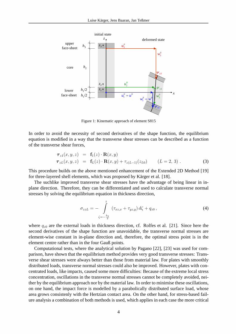
If a thin sandwich skin is impacted with high energies, and if the core is comparativelysoft, the skin experiences large deformations. In order to model the deformation behaviourstill correctly, the strain-displacement relation has to contain non-linear terms, which regardthe membran effect of large deflections. A suggestion considering membrane forces was madeby Olsson [27], who proposed an analytical membrane solution in addition to the plate so-lution for sandwich skins and observed its importance at higher indentations. Consequently,the sandwich element S815, which was introduced in section 2.1, was enhanced by non-linearstrain-displacement terms to account for large deflections.
To analyse the effects of non-linear strain terms, comparative computational tests were con-ducted: The above introduced sandwich panel was loaded by static loads, which representedthe impact load. In Fig. 12, the non-linear results for skin deflection and skin in-plane stressesare compared to linear results. It can be seen that the effect of non-linear strain terms is alreadyremarkable at deflections of about 3mm (for comparison: max. deflection at 8J impact were≈9mm, max. deflection at 1J impact were≈2mm, cf. Fig. 4). The reason why the static load Fin Fig. 12 is much larger than the impact forces in Figures 4, 8 and 11 is given by the fact thathere core degradation is not regarded. Nevertheless, for same deflections the effect of nonlinearterms is similarly valid with a degraded core, since the non-linearity mainly depends on thedisplacement state of the skin and not on the stress state in the core.
11
Luise Karger, Jens Baaran, Jan Teßmer
0
5
10
15
20
-30 -20 -10 0 10 20 30σxx in kN/mm²
linear
(top of impacted skin)
non-linear
0
5
10
15
20
0 5 10 15 20w in mm
F in
kN
σxx in kN/mm²(bottom of impacted skin)
Figure 12: Geometrical non-linearity: Deflection and in-plane stresses.
Recapitulating, at impact simulations with high energies, considering the non-linear strainterms of the impacted face sheet will result in smaller indentations and in smaller in-planestresses. Consequently, fibre breakage will be detected later than without geometrical non-linearity and the impact simulation will come closer to experimental results. However, includingthe geometrically non-linear element S815 in the impact analysis and modeling the fracturebehavior of the impacted skin is the subject of currently ongoing investigations.
3.5 Computational effort
Depending on the impact energy level and the extent of degradation, a CODAC simulationof a sandwich panel with the introduced mesh takes between 10sec and 1:30min on a personalcomputer with 2.3GHz. Due to its rapidity, the simulation is applicable for design processes.
4 CONCLUSION
The finite element tool CODAC and its methodology to efficiently simulate impacts on sand-wich structures was presented. A recently developed three-layered finite shell element allows anaccurate and efficient reproduction of stress and deformation behavior during impacts on sand-wich structures. The simulation was found to be mesh independent by parabolically distributingthe contact force according to the Hertzian contact area. Comparisons between impact tests andsimulations showed that the stiffness of the undamaged sandwich plate is well modeled.
An appropriate stress-based failure criteria for core crushing is capable of accurately detect-ing damage initiation. The material behavior of the damaged core is suitably described by arefined core degradation model. As a consequence, core damage sizes due to impact are wellpredicted. Moreover, impact events of low energy, which induce barely visible damage, can beaccurately and rapidly simulated.
At higher impact energies, the impacted face sheet experiences large deflection. It could beshown that before reaching a skin damaging load, it is essential to account for geometrical non-linearity in order to compute displacements and stresses correctly. Consequently, for predictingthe initiation of skin failure, non-linear strain terms have been included in the top skin layer ofthe proposed finite shell element. The implementation of the geometrically non-linear elementin the impact analysis is currently investigated.
12
Luise Karger, Jens Baaran, Jan Teßmer
ACKNOWLEDGMENT
The presented work is funded by the National Aeronautical Research Program. The authorsare grateful to the Department of Aerospace Technology at Dresden University (ILR Dresden)for conducting the test program and providing the experimental results. Furthermore, the helpof our student assistant Markus Kintscher by executing the computational test program is grate-fully acknowledged.
REFERENCES
[1] E.J. Herup and A.N. Palazotto, Low-velocity impact damage initiation ingraphite/epoxy/Nomex honeycomb-sandwich plates.Composite Science and Tech-nology, 57, 1581–1598, 1997.
[2] J. Gustin, A. Joneson, M. Mahinfalah, J. Stone, Low velocity impact of combinationKevlar/carbon fibre sandwich composites.Composite Structures, 69, 396–406, 2005.
[3] J.P. Dear, H. Lee, S.A. Brown, Impact damage processes in composite sheet and sandwichhoneycomb materials.International Journal of Impact Engineering, 32, 130–154, 2005.
[4] P.M. Schubel, J.-J. Luo, I.M. Daniel, Low velocity impact behavior of composite sandwichpanels.Composites Part A, 36, 1389–1396, 2005.
[5] R. Olsson, Prediction of impact damage in sandwich panels.Proc. Third Int. Conf. onSandwich Construction, 659–668, 1996.
[6] A. Petras, M.P.F. Sutcliffe, Indentation failure analysis of sandwich beams.CompositeStructures, 50, 311–318, 2000.
[7] M.S. Hoo Fatt, K.S. Park, Dynamic models for low-velocity impact damage of compositesandwich panels - Part B: Damage initiation.Composite Structures, 52, 353–364, 2001.
[8] R. Olsson, Engineering method for prediction of impact response and damage in sandwichpanels.Journal of Sandwich Structures and Materials, 4, 3–29, 2002.
[9] F. Hahnel, K. Wolf, Numerical simulation of CFRP honeycomb sandwich subjected tolow-velocity impact.Proc. Fifth Int. Conf. on Sandwich Construction, 2000.
[10] M. Meo, R. Vignjevic, G. Marengo, The response of honeycomb sandwich panels underlow-velocity impact loading.International Journal of Mechanical Sciences, 47, 1301–1325, 2005.
[11] M.Q. Nguyen, S.S. Jacombs, R.S. Thomson, D. Hachenberg, M.L. Scott, Simulation ofimpact on sandwich structures.Composite Structures, 67, 217–227, 2005.
[12] A.N. Palazotto, E.J. Herup, L.N.B. Gummadi, Finite element analysis of low-velocityimpact on composite sandwich plates.Composite Structures, 49, 209-227, 2000.
[13] T. Besant, G.A.O. Davies, D. Hitchings, Finite element modelling of low velocity impactof composite sandwich panels.Composites Part A, 32, 1189-1196, 2001.
13
Luise Karger, Jens Baaran, Jan Teßmer
[14] G.A.O. Davies, D. Hitchings, T. Besant, A. Clarke, C. Morgan. Compression after impactstrength of composite sandwich panels.Composite Structures, 63, 1-9, 2004.
[15] L. Karger, J. Baaran and J. Teßmer, Rapid Simulation of Impacts on Composite SandwichPanels Inducing Barely Visible Damage.Composite Structures, in press, 2006.
[16] R. Rolfes, J. Baaran, J. Juhasz, A. Kling, Ph. Nolden and G. Kuhlmann, High PerformanceTools for Failure, Damage Tolerance and Stability Analysis of Composite Structures.Pro-ceedings WCCM V, Vienna, 2002.
[17] J. Baaran, L. Karger and A. Wetzel, CODAC Version 1.6 Manual.DLR, Institute FA,Braunschweig, Internal Report IB 131-2005/38, 2005.
[18] L. Karger, A. Wetzel, R. Rolfes and K. Rohwer, A three-layered sandwich element withimproved transverse shear stiffness and stresses based on FSDT.Computers and Struc-tures, in press, 2006.
[19] R. Rolfes and K. Rohwer, Improved transverse shear stresses in composite finite elementsbased on first order shear deformation theory.International Journal for Numerical Meth-ods in Engineering, 40, 51–60, 1997.
[20] A. Wetzel, L. Karger, R. Rolfes and K. Rohwer, Evaluation of two finite element formula-tions for a rapid 3D stress analysis of sandwich structures.Computers and Structures, 83,1537-1545, 2005.
[21] R. Rolfes, K. Rohwer and M. Ballerstaedt, Efficient Linear Transverse Normal StressAnalysis of Layered Composite Plates.Computers and Structures, 68, 643–652, 1998.
[22] N.J. Pagano, Exact solutions for composite laminates in cylindrical bending.Journal ofComposite Materials, 3, 398–411, 1969.
[23] N.J. Pagano, Exact solutions for rectangular bidirectional composites and sandwich plates.Journal of Composite Materials, 4, 20–34, 1970.
[24] K. Wolf, F. Hahnel and K. Steinbach, Internal communications. Department of AerospaceTechnology, Dresden University of Technology.
[25] Z. Hashin, Failure Criteria for Unidirectional Fibre Composites.Journal of Applied Me-chanics, 47, 329-334, 1980.
[26] F.-K. Chang, K.-Y Chang, A progressive damage model for laminated composites con-taining stress concentrations.Journal of Composite Materials, 21, 834-855, 1987.
[27] R. Olsson, Improved theory for contact indentation of sandwich panels.AIAA Journal, 6,1238-1244, 1996.