Page 1
International Journal on Recent Technologies in Mechanical and Electrical Engineering (IJRMEE) ISSN: 2349 - 7947 Volume: 3 Issue: 1 07 - 18
_______________________________________________________________________________________________
7 IJRMEE | January 2016, Available @ http://www.ijrmee.org
_______________________________________________________________________________________
FEA and Optimization of Catalyst Bed Reactor Vessel
Navin S. Nagpurkar
Alard college of engineering and management
Pune, India
Email-id: [email protected]
Prof. N. H. Ambhore
V.I.I.T.,
Pune, India
Abstract— A Catalyst Bed Reactor (CBR) is a reactor compartment incorporated in a pressure vessel that can be used to carry out
a variety of multiphase chemical reactions. In this type of reactor, a fluid (gas or liquid) is passed through a granular solid material
(usually a catalyst possibly shaped as tiny spheres) at high enough velocities to suspend the solid and cause it to behave as though
it were a fluid.
Catalyst bed is a popular technique to speed up chemical processes. However current designs of a bed are stagnant designs where
the chemical reaction occurs while the fluid is stationary, as if in a storage vessel. This process is time expensive and hence there
is need of speeding up the process in which the fluid flow is present. This can be achieved in a reactor vessel where the Catalyst
bed is embedded in the design.
This design has its own challenges. When the reaction takes place, some quantity of the catalyst stagnates, and this stagnation has
to be removed, which is done using inclined nozzles. These inclined nozzles are a design headache as they create a lot of stress
zones. Thus, our objective is to find out the best solution out for this problem so as to enhance the process and to get the best
results while performing actual analysis for the vessel under consideration.
Keywords- Pressure vessels, Nozzles, Reactor vessel, FEA, Optimization, Stress distribution, Stress concentration, Stress
concentration factor, Deformation, Equivalent Von Mises stresses.
__________________________________________________*****_________________________________________________
I. INTRODUCTION
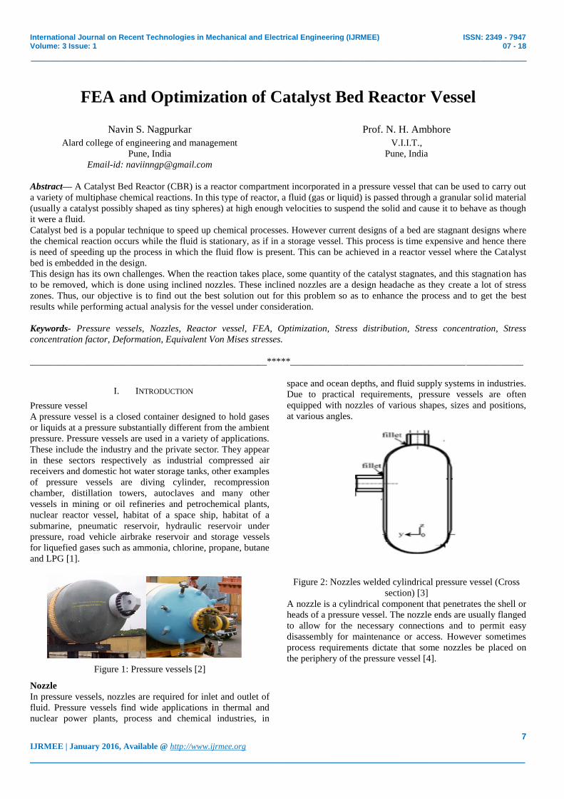
Pressure vessel
A pressure vessel is a closed container designed to hold gases
or liquids at a pressure substantially different from the ambient
pressure. Pressure vessels are used in a variety of applications.
These include the industry and the private sector. They appear
in these sectors respectively as industrial compressed air
receivers and domestic hot water storage tanks, other examples
of pressure vessels are diving cylinder, recompression
chamber, distillation towers, autoclaves and many other
vessels in mining or oil refineries and petrochemical plants,
nuclear reactor vessel, habitat of a space ship, habitat of a
submarine, pneumatic reservoir, hydraulic reservoir under
pressure, road vehicle airbrake reservoir and storage vessels
for liquefied gases such as ammonia, chlorine, propane, butane
and LPG [1].
Figure 1: Pressure vessels [2]
Nozzle
In pressure vessels, nozzles are required for inlet and outlet of
fluid. Pressure vessels find wide applications in thermal and
nuclear power plants, process and chemical industries, in
space and ocean depths, and fluid supply systems in industries.
Due to practical requirements, pressure vessels are often
equipped with nozzles of various shapes, sizes and positions,
at various angles.
Figure 2: Nozzles welded cylindrical pressure vessel (Cross
section) [3]
A nozzle is a cylindrical component that penetrates the shell or
heads of a pressure vessel. The nozzle ends are usually flanged
to allow for the necessary connections and to permit easy
disassembly for maintenance or access. However sometimes
process requirements dictate that some nozzles be placed on
the periphery of the pressure vessel [4].
Page 2
International Journal on Recent Technologies in Mechanical and Electrical Engineering (IJRMEE) ISSN: 2349 - 7947 Volume: 3 Issue: 1 07 - 18
_______________________________________________________________________________________________
8 IJRMEE | January 2016, Available @ http://www.ijrmee.org
_______________________________________________________________________________________
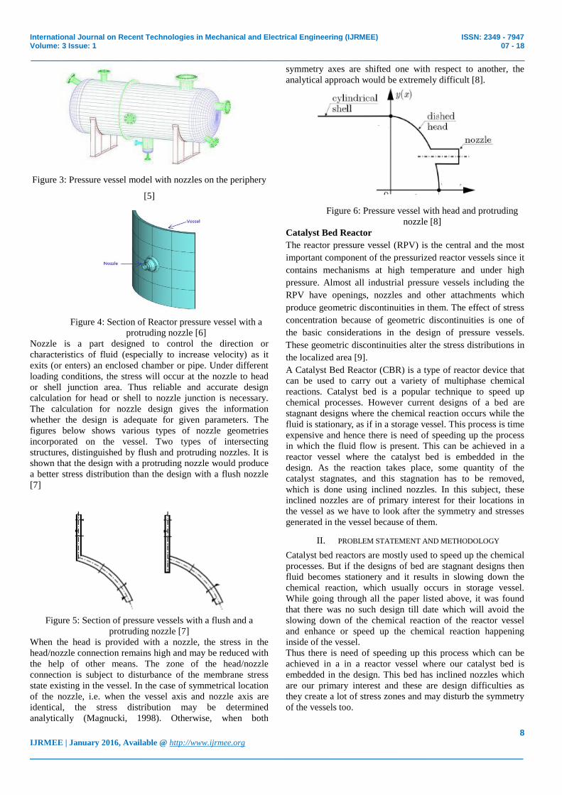
Figure 3: Pressure vessel model with nozzles on the periphery
[5]
Figure 4: Section of Reactor pressure vessel with a
protruding nozzle [6]
Nozzle is a part designed to control the direction or
characteristics of fluid (especially to increase velocity) as it
exits (or enters) an enclosed chamber or pipe. Under different
loading conditions, the stress will occur at the nozzle to head
or shell junction area. Thus reliable and accurate design
calculation for head or shell to nozzle junction is necessary.
The calculation for nozzle design gives the information
whether the design is adequate for given parameters. The
figures below shows various types of nozzle geometries
incorporated on the vessel. Two types of intersecting
structures, distinguished by flush and protruding nozzles. It is
shown that the design with a protruding nozzle would produce
a better stress distribution than the design with a flush nozzle
[7]
Figure 5: Section of pressure vessels with a flush and a
protruding nozzle [7]
When the head is provided with a nozzle, the stress in the
head/nozzle connection remains high and may be reduced with
the help of other means. The zone of the head/nozzle
connection is subject to disturbance of the membrane stress
state existing in the vessel. In the case of symmetrical location
of the nozzle, i.e. when the vessel axis and nozzle axis are
identical, the stress distribution may be determined
analytically (Magnucki, 1998). Otherwise, when both
symmetry axes are shifted one with respect to another, the
analytical approach would be extremely difficult [8].
Figure 6: Pressure vessel with head and protruding
nozzle [8]
Catalyst Bed Reactor
The reactor pressure vessel (RPV) is the central and the most
important component of the pressurized reactor vessels since it
contains mechanisms at high temperature and under high
pressure. Almost all industrial pressure vessels including the
RPV have openings, nozzles and other attachments which
produce geometric discontinuities in them. The effect of stress
concentration because of geometric discontinuities is one of
the basic considerations in the design of pressure vessels.
These geometric discontinuities alter the stress distributions in
the localized area [9].
A Catalyst Bed Reactor (CBR) is a type of reactor device that
can be used to carry out a variety of multiphase chemical
reactions. Catalyst bed is a popular technique to speed up
chemical processes. However current designs of a bed are
stagnant designs where the chemical reaction occurs while the
fluid is stationary, as if in a storage vessel. This process is time
expensive and hence there is need of speeding up the process
in which the fluid flow is present. This can be achieved in a
reactor vessel where the catalyst bed is embedded in the
design. As the reaction takes place, some quantity of the
catalyst stagnates, and this stagnation has to be removed,
which is done using inclined nozzles. In this subject, these
inclined nozzles are of primary interest for their locations in
the vessel as we have to look after the symmetry and stresses
generated in the vessel because of them.
II. PROBLEM STATEMENT AND METHODOLOGY
Catalyst bed reactors are mostly used to speed up the chemical
processes. But if the designs of bed are stagnant designs then
fluid becomes stationery and it results in slowing down the
chemical reaction, which usually occurs in storage vessel.
While going through all the paper listed above, it was found
that there was no such design till date which will avoid the
slowing down of the chemical reaction of the reactor vessel
and enhance or speed up the chemical reaction happening
inside of the vessel.
Thus there is need of speeding up this process which can be
achieved in a in a reactor vessel where our catalyst bed is
embedded in the design. This bed has inclined nozzles which
are our primary interest and these are design difficulties as
they create a lot of stress zones and may disturb the symmetry
of the vessels too.
Page 3
International Journal on Recent Technologies in Mechanical and Electrical Engineering (IJRMEE) ISSN: 2349 - 7947 Volume: 3 Issue: 1 07 - 18
_______________________________________________________________________________________________
9 IJRMEE | January 2016, Available @ http://www.ijrmee.org
_______________________________________________________________________________________
Figure 7: Ellipsoidal head & nozzle shell intersection
(Unsymmetrical geometry) [10]
Objective
We will be dealing with FEA (Finite element analysis method)
for below objectives;
1. To design a pressure vessel incorporated with nozzles and
find out the required thickness for the vessel.
2. To conduct the static structural stress analysis of the
pressure vessel and nozzles at given angular positions
3. To find out the optimum thickness for the vessel at which
vessel will be stabilized in terms of deformation and
stresses generated.
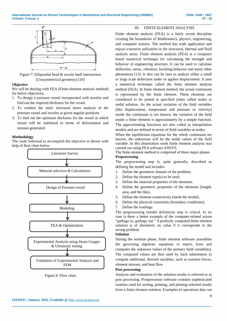
Methodology
The route followed to accomplish the objective is shown with
help of flow chart below
Figure 8: Flow chart
III. FINITE ELEMENT ANALYSIS
Finite element analysis (FEA) is a fairly recent discipline
crossing the boundaries of Mathematics, physics, engineering,
and computer science. The method has wide application and
enjoys extensive utilization in the structural, thermal and fluid
analysis areas. Finite element analysis (FEA) is a computer
based numerical technique for calculating the strength and
behavior of engineering structure. It can be used to calculate
deflection, stress, vibration, buckling behavior and many other
phenomena [13]. It also can be uses to analyze either a small
or large scale deflection under or applies displacement. It uses
a numerical technique called the finite element analysis
method (FEA). In finite element method, the actual continuum
is represented by the finite element. These elements are
considered to be joined at specified joints called nodes or
nodal solution. As the actual variation of the field variables
(like displacement, temperature and pressure or velocity)
inside the continuum is not known, the variation of the field
inside a finite element is approximately by a simple function.
The approximating functions are also called as interpolation
models and are defined in terms of field variables at nodes.
When the equilibrium equations for the whole continuum are
known, the unknowns will be the nodal values of the field
variable. In this dissertation work finite element analysis was
carried out using FEA software ANSYS.
The finite element method is comprised of three major phases
Preprocessing
The preprocessing step is, quite generally, described as
defining the model and includes
1. Define the geometric domain of the problem.
2. Define the element type(s) to be used.
3. Define the material properties of the elements.
4. Define the geometric properties of the elements (length,
area, and the like).
5. Define the element connectivity (mesh the model).
6. Define the physical constraints (boundary conditions).
7. Define the loadings.
The preprocessing (model definition) step is critical. In no
case is there a better example of the computer-related axiom
“garbage in, garbage out.” A perfectly computed finite element
solution is of absolutely no value if it corresponds to the
wrong problem.
Solution
During the solution phase, finite element software assembles
the governing algebraic equations in matrix form and
computes the unknown values of the primary field variable(s).
The computed values are then used by back substitution to
compute additional, derived variables, such as reaction forces,
element stresses, and heat flow.
Post processing
Analysis and evaluation of the solution results is referred to as
post processing. Postprocessor software contains sophisticated
routines used for sorting, printing, and plotting selected results
from a finite element solution. Examples of operations that can
Literature Survey
Material selection & Calculations
Design of Pressure vessel
Modeling
FEA & Optimization
Experimental Analysis using Strain Gauges
& Ultrasonic testing
Validation of Experimental Analysis and
FEM
Page 4
International Journal on Recent Technologies in Mechanical and Electrical Engineering (IJRMEE) ISSN: 2349 - 7947 Volume: 3 Issue: 1 07 - 18
_______________________________________________________________________________________________
10 IJRMEE | January 2016, Available @ http://www.ijrmee.org
_______________________________________________________________________________________
be accomplished include
1. SFD,BMD,AFD
2. Check equilibrium
3. Plot deformed structural shape
4. Animate dynamic model behavior
5. Produce color coded temperature plots
While solution data can be manipulated many ways in post
processing, the most important objective is to apply sound
engineering judgment in determining whether the solution
results are physically reasonable.
IV. MODEL SELECTION AND FEA OF CATALYST BED
REACTOR VESSEL
Modelling
The first step of pre-processing is to generate the 3-D model of
the given component which is compatible to import in the
solver. The 3-D model of the Pressure vessel is created in
Ansys 15 work bench using the dimensions calculated in the
previous chapter and using some input given by the company.
The model of vertical pressure vessel is shown in Figure 4.3.
These files were used for further analysis process. The two
nozzles were added in the model at 45° to the vertical vessel.
The intention of the addition of the nozzles is to enhance the
chemical reaction occurring in the catalyst bed reactor vessel.
The concept of the inclined nozzles is to speed up the flow of
the fluid coming from the entry nozzle thus adding extra
velocity to the flow. This way, we can remove the stagnation
of the reaction happening in the catalyst bed.
The first vessel model was created for the vertical erection and
to achieve this erection, the skirt support was provided. But,
keeping an eye on horizontal pressure / load i.e. 41 km/hr, it
was analyzed for the vertical stability of the vessel and the
images below shows the results we got. It can be clearly seen
that vessels are not able to sustain the horizontal wind load of
41 km/hr and hence it was suggested to lay the vessel in
horizontal position. Therefore, as per the recommendation we
need to incorporate the saddles for the horizontal support.
Saddles are provided to lay the pressure vessel in horizontal
position, since pressure vessel was unable to withstand the
horizontal wind loads and the generated equivalent stress and
the deformation were more than the allowable values. Snaps
are taken from Ansys to reflect the results for the vertical
instability of the vessel (Refer figure 4.5).
The next step involved with the horizontal pressure vessel was
to design the saddle supports for the vessel. Looking at the
large height (now length) of the vessel 3 saddles were
recommended to support the vessel [24]. The saddles were
designed are now working as supports.
This horizontal vessel was then checked for stability. All the
bounary conditions like pressure, standard Earth gravity, force
were added.and all the supports were fixed. Modal was solved
with all these conditions. It was solved for deformation and
equivalent Von Mises stresses and the results were obtained.
But the issue happened with this case was the frequency of the
model was coming out to be zero.
Figure 9: Pressure vessel with zero frequency
The figure 9 shows the model deformation, frequency graph
and chart at an actual scale. The first three frequency are
coming out to be zero. But every single object in our day to
day life must have some frequency. The zero frequency means
it is in space.
To correct the discrepancy, this issue is checked for the
contact of the elements created while modelling. All the
contacts were detcted and the issue was resolved. Then, again
the solve command was given and now the results were
obtained with the non zero frequency. This is known as model
validation and hence, now we can further proceed with the
analysis of the vessel.
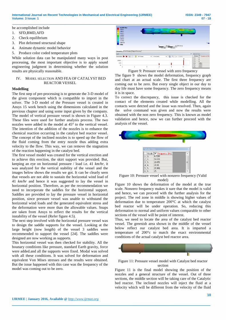
Figure 10: Pressure vessel with nonzero frequency (Valid
model)
Figure 10 shows the deformation of the model at the true
scale. Nonzero frequency makes it sure that the model is valid
and hence, we can proceed with the further analysis for the
project. The red zone in middle is showing higher values of
deformation due to temperature 200°C at which the catalyst
bed reactor will be under operation. So, reducing this
deformation to normal and uniform values comparable to other
sections of the vessel will be point of interest.
Thus, we need to locate the area of the catalyst bed reactor
vessel. The greenish area shown in the middle of the vessel
below reflect our catalyst bed area. It is imparted a
temperature of 200°c to match the exact environmental
conditions of the actual catalyst bed reactor area.
Figure 11: Pressure vessel model with Catalyst bed reactor
section
Figure 11 is the final model showing the position of the
nozzles and a general structure of the vessel. Out of three
sections, the middle section will be taking care of the Catalytic
bed reactor. The inclined nozzles will inject the fluid at a
velocity which will be different from the velocity of the fluid
Page 5
International Journal on Recent Technologies in Mechanical and Electrical Engineering (IJRMEE) ISSN: 2349 - 7947 Volume: 3 Issue: 1 07 - 18
_______________________________________________________________________________________________
11 IJRMEE | January 2016, Available @ http://www.ijrmee.org
_______________________________________________________________________________________
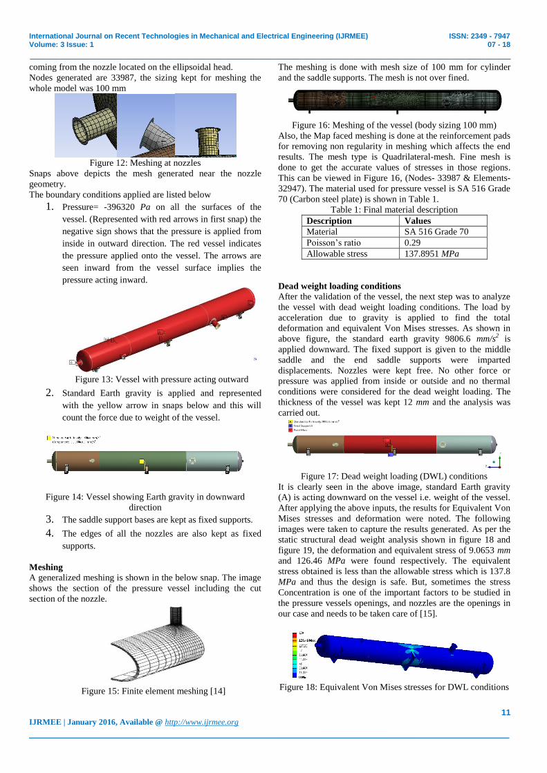
coming from the nozzle located on the ellipsoidal head.
Nodes generated are 33987, the sizing kept for meshing the
whole model was 100 mm
Figure 12: Meshing at nozzles
Snaps above depicts the mesh generated near the nozzle
geometry.
The boundary conditions applied are listed below
1. Pressure= -396320 Pa on all the surfaces of the
vessel. (Represented with red arrows in first snap) the
negative sign shows that the pressure is applied from
inside in outward direction. The red vessel indicates
the pressure applied onto the vessel. The arrows are
seen inward from the vessel surface implies the
pressure acting inward.
Figure 13: Vessel with pressure acting outward
2. Standard Earth gravity is applied and represented
with the yellow arrow in snaps below and this will
count the force due to weight of the vessel.
Figure 14: Vessel showing Earth gravity in downward
direction
3. The saddle support bases are kept as fixed supports.
4. The edges of all the nozzles are also kept as fixed
supports.
Meshing A generalized meshing is shown in the below snap. The image
shows the section of the pressure vessel including the cut
section of the nozzle.
Figure 15: Finite element meshing [14]
The meshing is done with mesh size of 100 mm for cylinder
and the saddle supports. The mesh is not over fined.
Figure 16: Meshing of the vessel (body sizing 100 mm)
Also, the Map faced meshing is done at the reinforcement pads
for removing non regularity in meshing which affects the end
results. The mesh type is Quadrilateral-mesh. Fine mesh is
done to get the accurate values of stresses in those regions.
This can be viewed in Figure 16, (Nodes- 33987 & Elements-
32947). The material used for pressure vessel is SA 516 Grade
70 (Carbon steel plate) is shown in Table 1.
Table 1: Final material description
Description Values
Material SA 516 Grade 70
Poisson‟s ratio 0.29
Allowable stress 137.8951 MPa
Dead weight loading conditions
After the validation of the vessel, the next step was to analyze
the vessel with dead weight loading conditions. The load by
acceleration due to gravity is applied to find the total
deformation and equivalent Von Mises stresses. As shown in
above figure, the standard earth gravity 9806.6 mm/s2 is
applied downward. The fixed support is given to the middle
saddle and the end saddle supports were imparted
displacements. Nozzles were kept free. No other force or
pressure was applied from inside or outside and no thermal
conditions were considered for the dead weight loading. The
thickness of the vessel was kept 12 mm and the analysis was
carried out.
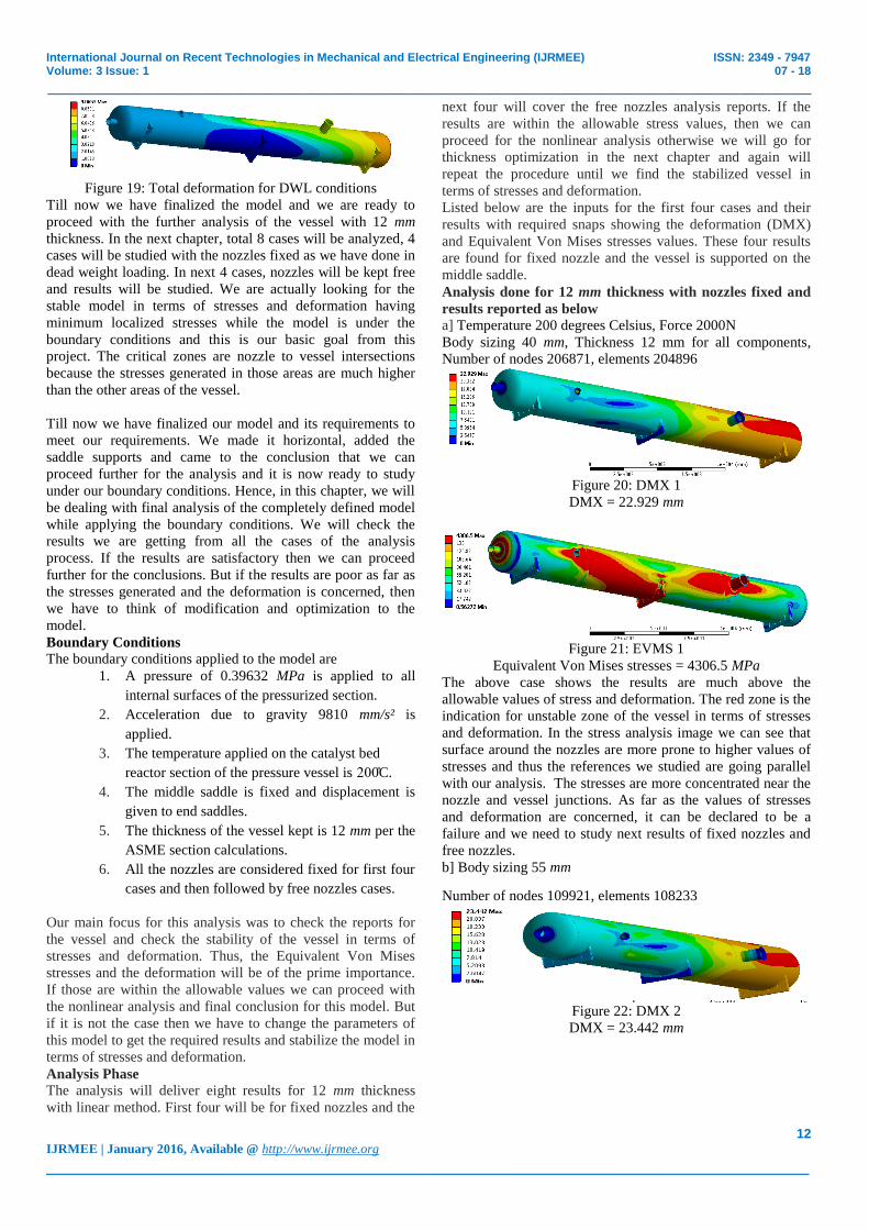
Figure 17: Dead weight loading (DWL) conditions
It is clearly seen in the above image, standard Earth gravity
(A) is acting downward on the vessel i.e. weight of the vessel.
After applying the above inputs, the results for Equivalent Von
Mises stresses and deformation were noted. The following
images were taken to capture the results generated. As per the
static structural dead weight analysis shown in figure 18 and
figure 19, the deformation and equivalent stress of 9.0653 mm
and 126.46 MPa were found respectively. The equivalent
stress obtained is less than the allowable stress which is 137.8
MPa and thus the design is safe. But, sometimes the stress
Concentration is one of the important factors to be studied in
the pressure vessels openings, and nozzles are the openings in
our case and needs to be taken care of [15].
Figure 18: Equivalent Von Mises stresses for DWL conditions
Page 6
International Journal on Recent Technologies in Mechanical and Electrical Engineering (IJRMEE) ISSN: 2349 - 7947 Volume: 3 Issue: 1 07 - 18
_______________________________________________________________________________________________
12 IJRMEE | January 2016, Available @ http://www.ijrmee.org
_______________________________________________________________________________________
Figure 19: Total deformation for DWL conditions
Till now we have finalized the model and we are ready to
proceed with the further analysis of the vessel with 12 mm
thickness. In the next chapter, total 8 cases will be analyzed, 4
cases will be studied with the nozzles fixed as we have done in
dead weight loading. In next 4 cases, nozzles will be kept free
and results will be studied. We are actually looking for the
stable model in terms of stresses and deformation having
minimum localized stresses while the model is under the
boundary conditions and this is our basic goal from this
project. The critical zones are nozzle to vessel intersections
because the stresses generated in those areas are much higher
than the other areas of the vessel.
Till now we have finalized our model and its requirements to
meet our requirements. We made it horizontal, added the
saddle supports and came to the conclusion that we can
proceed further for the analysis and it is now ready to study
under our boundary conditions. Hence, in this chapter, we will
be dealing with final analysis of the completely defined model
while applying the boundary conditions. We will check the
results we are getting from all the cases of the analysis
process. If the results are satisfactory then we can proceed
further for the conclusions. But if the results are poor as far as
the stresses generated and the deformation is concerned, then
we have to think of modification and optimization to the
model.
Boundary Conditions The boundary conditions applied to the model are
1. A pressure of 0.39632 MPa is applied to all
internal surfaces of the pressurized section.
2. Acceleration due to gravity 9810 mm/s² is
applied.
3. The temperature applied on the catalyst bed
reactor section of the pressure vessel is 200C̊.
4. The middle saddle is fixed and displacement is
given to end saddles.
5. The thickness of the vessel kept is 12 mm per the
ASME section calculations.
6. All the nozzles are considered fixed for first four
cases and then followed by free nozzles cases.
Our main focus for this analysis was to check the reports for
the vessel and check the stability of the vessel in terms of
stresses and deformation. Thus, the Equivalent Von Mises
stresses and the deformation will be of the prime importance.
If those are within the allowable values we can proceed with
the nonlinear analysis and final conclusion for this model. But
if it is not the case then we have to change the parameters of
this model to get the required results and stabilize the model in
terms of stresses and deformation.
Analysis Phase
The analysis will deliver eight results for 12 mm thickness
with linear method. First four will be for fixed nozzles and the
next four will cover the free nozzles analysis reports. If the
results are within the allowable stress values, then we can
proceed for the nonlinear analysis otherwise we will go for
thickness optimization in the next chapter and again will
repeat the procedure until we find the stabilized vessel in
terms of stresses and deformation.
Listed below are the inputs for the first four cases and their
results with required snaps showing the deformation (DMX)
and Equivalent Von Mises stresses values. These four results
are found for fixed nozzle and the vessel is supported on the
middle saddle.
Analysis done for 12 mm thickness with nozzles fixed and
results reported as below
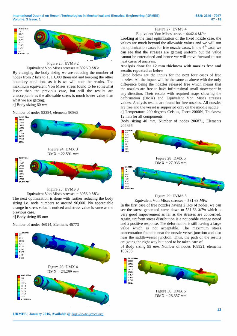
a] Temperature 200 degrees Celsius, Force 2000N
Body sizing 40 mm, Thickness 12 mm for all components,
Number of nodes 206871, elements 204896
Figure 20: DMX 1
DMX = 22.929 mm
Figure 21: EVMS 1
Equivalent Von Mises stresses = 4306.5 MPa
The above case shows the results are much above the
allowable values of stress and deformation. The red zone is the
indication for unstable zone of the vessel in terms of stresses
and deformation. In the stress analysis image we can see that
surface around the nozzles are more prone to higher values of
stresses and thus the references we studied are going parallel
with our analysis. The stresses are more concentrated near the
nozzle and vessel junctions. As far as the values of stresses
and deformation are concerned, it can be declared to be a
failure and we need to study next results of fixed nozzles and
free nozzles.
b] Body sizing 55 mm
Number of nodes 109921, elements 108233
Figure 22: DMX 2
DMX = 23.442 mm
Page 7
International Journal on Recent Technologies in Mechanical and Electrical Engineering (IJRMEE) ISSN: 2349 - 7947 Volume: 3 Issue: 1 07 - 18
_______________________________________________________________________________________________
13 IJRMEE | January 2016, Available @ http://www.ijrmee.org
_______________________________________________________________________________________
Figure 23: EVMS 2
Equivalent Von Mises stresses = 3926.9 MPa
By changing the body sizing we are reducing the number of
nodes from 2 lacs to 1, 10,000 thousand and keeping the other
boundary conditions as it is we will note the results. The
maximum equivalent Von Mises stress found to be somewhat
lesser than the previous case, but still the results are
unacceptable as the allowable stress is much lower value than
what we are getting.
c] Body sizing 60 mm
Number of nodes 92384, elements 90865
Figure 24: DMX 3
DMX = 22.591 mm
Figure 25: EVMS 3
Equivalent Von Mises stresses = 3956.9 MPa
The next optimization is done with further reducing the body
sizing i.e. node numbers to around 90,000. No appreciable
change in stress value is noticed and stress value is same as the
previous case.
d] Body sizing 85 mm
Number of nodes 46914, Elements 45773
Figure 26: DMX 4
DMX = 23.299 mm
Figure 27: EVMS 4
Equivalent Von Mises stress = 4442.4 MPa
Looking at the final optimization of the fixed nozzle case, the
values are much beyond the allowable values and we will run
the optimization cases for free nozzle cases. In the 4th
case, we
can see that the stresses are getting uniform but the value
cannot be entertained and hence we will move forward to our
next cases of analysis.
Analysis done for 12 mm thickness with nozzles free and
results reported as below Listed below are the inputs for the next four cases of free
nozzles. All the inputs will be the same as above with the only
difference being the nozzles released free which means that
the nozzles are free to have infinitesimal small movement in
any direction. Their results with required snaps showing the
deformation (DMX) and Equivalent Von Mises stresses
values. Analysis results are found for free nozzles. All nozzles
are free and the vessel is supported only on the middle saddle.
a] Temperature 200 degrees Celsius, Force 2000N, Thickness
12 mm for all components,
Body sizing 40 mm, Number of nodes 206871, Elements
204896
Figure 28: DMX 5
DMX = 27.936 mm
Figure 29: EVMS 5
Equivalent Von Mises stresses = 531.68 MPa
In the first case of free nozzles having 2 lacs of nodes, we can
see the stress generated came down to 531.68 MPa which is
very good improvement as far as the stresses are concerned.
Again, uniform stress distribution is a noticeable change noted
and a positive response. The deformation is still having a large
value which is not acceptable. The maximum stress
concentration found is near the nozzle-vessel junction and also
near the saddle-vessel junction. Thus, the path of the results
are going the right way but need to be taken care of.
b] Body sizing 55 mm, Number of nodes 109921, elements
108233
Figure 30: DMX 6
DMX = 28.357 mm
Page 8
International Journal on Recent Technologies in Mechanical and Electrical Engineering (IJRMEE) ISSN: 2349 - 7947 Volume: 3 Issue: 1 07 - 18
_______________________________________________________________________________________________
14 IJRMEE | January 2016, Available @ http://www.ijrmee.org
_______________________________________________________________________________________
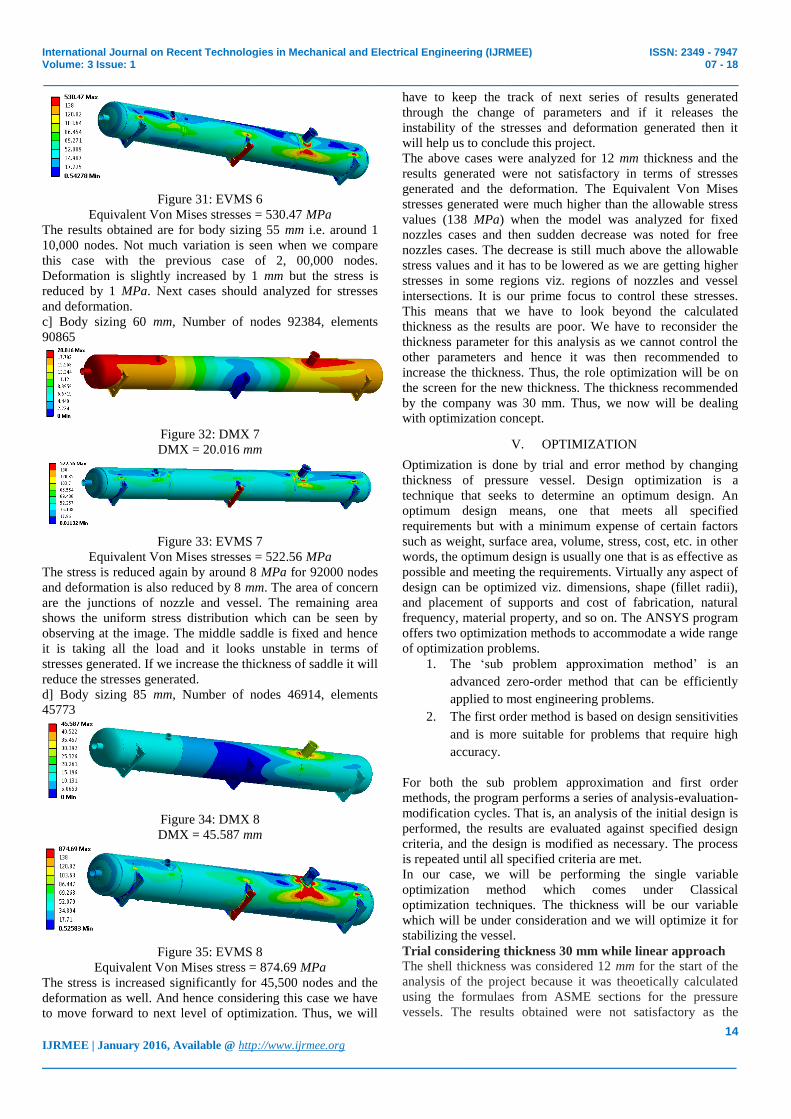
Figure 31: EVMS 6
Equivalent Von Mises stresses = 530.47 MPa
The results obtained are for body sizing 55 mm i.e. around 1
10,000 nodes. Not much variation is seen when we compare
this case with the previous case of 2, 00,000 nodes.
Deformation is slightly increased by 1 mm but the stress is
reduced by 1 MPa. Next cases should analyzed for stresses
and deformation.
c] Body sizing 60 mm, Number of nodes 92384, elements
90865
Figure 32: DMX 7
DMX = 20.016 mm
Figure 33: EVMS 7
Equivalent Von Mises stresses = 522.56 MPa
The stress is reduced again by around 8 MPa for 92000 nodes
and deformation is also reduced by 8 mm. The area of concern
are the junctions of nozzle and vessel. The remaining area
shows the uniform stress distribution which can be seen by
observing at the image. The middle saddle is fixed and hence
it is taking all the load and it looks unstable in terms of
stresses generated. If we increase the thickness of saddle it will
reduce the stresses generated.
d] Body sizing 85 mm, Number of nodes 46914, elements
45773
Figure 34: DMX 8
DMX = 45.587 mm
Figure 35: EVMS 8
Equivalent Von Mises stress = 874.69 MPa
The stress is increased significantly for 45,500 nodes and the
deformation as well. And hence considering this case we have
to move forward to next level of optimization. Thus, we will
have to keep the track of next series of results generated
through the change of parameters and if it releases the
instability of the stresses and deformation generated then it
will help us to conclude this project.
The above cases were analyzed for 12 mm thickness and the
results generated were not satisfactory in terms of stresses
generated and the deformation. The Equivalent Von Mises
stresses generated were much higher than the allowable stress
values (138 MPa) when the model was analyzed for fixed
nozzles cases and then sudden decrease was noted for free
nozzles cases. The decrease is still much above the allowable
stress values and it has to be lowered as we are getting higher
stresses in some regions viz. regions of nozzles and vessel
intersections. It is our prime focus to control these stresses.
This means that we have to look beyond the calculated
thickness as the results are poor. We have to reconsider the
thickness parameter for this analysis as we cannot control the
other parameters and hence it was then recommended to
increase the thickness. Thus, the role optimization will be on
the screen for the new thickness. The thickness recommended
by the company was 30 mm. Thus, we now will be dealing
with optimization concept.
V. OPTIMIZATION
Optimization is done by trial and error method by changing
thickness of pressure vessel. Design optimization is a
technique that seeks to determine an optimum design. An
optimum design means, one that meets all specified
requirements but with a minimum expense of certain factors
such as weight, surface area, volume, stress, cost, etc. in other
words, the optimum design is usually one that is as effective as
possible and meeting the requirements. Virtually any aspect of
design can be optimized viz. dimensions, shape (fillet radii),
and placement of supports and cost of fabrication, natural
frequency, material property, and so on. The ANSYS program
offers two optimization methods to accommodate a wide range
of optimization problems.
1. The „sub problem approximation method‟ is an
advanced zero-order method that can be efficiently
applied to most engineering problems.
2. The first order method is based on design sensitivities
and is more suitable for problems that require high
accuracy.
For both the sub problem approximation and first order
methods, the program performs a series of analysis-evaluation-
modification cycles. That is, an analysis of the initial design is
performed, the results are evaluated against specified design
criteria, and the design is modified as necessary. The process
is repeated until all specified criteria are met.
In our case, we will be performing the single variable
optimization method which comes under Classical
optimization techniques. The thickness will be our variable
which will be under consideration and we will optimize it for
stabilizing the vessel.
Trial considering thickness 30 mm while linear approach
The shell thickness was considered 12 mm for the start of the
analysis of the project because it was theoetically calculated
using the formulaes from ASME sections for the pressure
vessels. The results obtained were not satisfactory as the
Page 9
International Journal on Recent Technologies in Mechanical and Electrical Engineering (IJRMEE) ISSN: 2349 - 7947 Volume: 3 Issue: 1 07 - 18
_______________________________________________________________________________________________
15 IJRMEE | January 2016, Available @ http://www.ijrmee.org
_______________________________________________________________________________________
deformations (DMX) and the equivalent Von Mises stresses
generated were multiple times higher than allowable stresses
and hence we have to make a move towards a new thickness
so as to get the more better results which will satisfy our
objective and stabilize the nozzle in terms of the stresses
generated and minimum deformation.
Following are the cases studied for pressure vessel with 30
mm shell thickness. All nozzles are fixed and supported only
on the middle saddle.
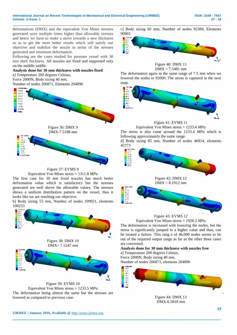
Analysis done for 30 mm thickness with nozzles fixed
a] Temperature 200 degrees Celsius,
Force 2000N, Body sizing 40 mm,
Number of nodes 206871, Elements 204896
Figure 36: DMX 9
DMX-7.5188 mm
Figure 37: EVMS 9
Equivalent Von Mises stress = 1311.8 MPa
The first case for 30 mm fixed nozzles has much better
deformation value which is satisfactory but the stresses
generated are well above the allowable values. The stresses
shows a uniform distribution pattern on the vessel, thus it
looks like we are reaching our objective.
b] Body sizing 55 mm, Number of nodes 109921, elements
108233
Figure 38: DMX 10
DMX= 7.5247 mm
Figure 39: EVMS 10
Equivalent Von Mises stress = 1233.5 MPa
The deformation being almost the same but the stresses are
lowered as compared to previous case.
c] Body sizing 60 mm, Number of nodes 92384, Elements
90865
Figure 40: DMX 11
DMX = 7.5481 mm
The deformation again in the same range of 7.5 mm when we
lowered the nodes to 92000. The stress is captured in the next
snap.
Figure 41: EVMS 11
Equivalent Von Mises stress = 1233.4 MPa
The stress is also came around the 1233.4 MPa which is
following approximately the same range.
d] Body sizing 85 mm, Number of nodes 46914, elements
45773
Figure 42: DMX 12
DMX = 8.1912 mm
Figure 43: EVMS 12
Equivalent Von Mises stress = 1928.3 MPa
The deformation is increased with lowering the nodes, but the
stress is significantly jumped to a higher value and thus, can
be treated a failure. This rang e of 46,000 nodes seems to be
out of the required output range as far as the other three cases
are concerned.
Analysis done for 30 mm thickness with nozzles free
a] Temperature 200 degrees Celsius,
Force 2000N, Body sizing 40 mm,
Number of nodes 206871, elements 204896
Figure 44: DMX 13
DMX-6.5818 mm
Page 10
International Journal on Recent Technologies in Mechanical and Electrical Engineering (IJRMEE) ISSN: 2349 - 7947 Volume: 3 Issue: 1 07 - 18
_______________________________________________________________________________________________
16 IJRMEE | January 2016, Available @ http://www.ijrmee.org
_______________________________________________________________________________________
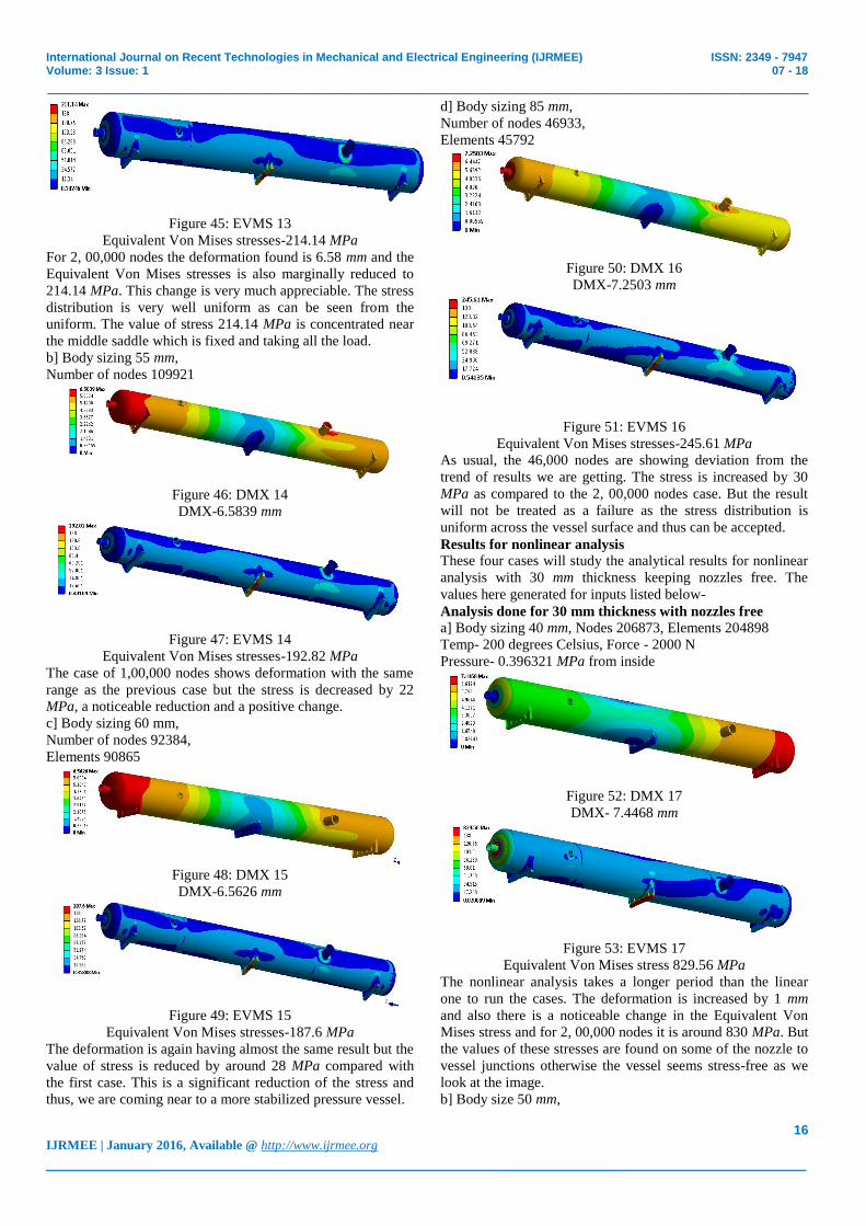
Figure 45: EVMS 13
Equivalent Von Mises stresses-214.14 MPa
For 2, 00,000 nodes the deformation found is 6.58 mm and the
Equivalent Von Mises stresses is also marginally reduced to
214.14 MPa. This change is very much appreciable. The stress
distribution is very well uniform as can be seen from the
uniform. The value of stress 214.14 MPa is concentrated near
the middle saddle which is fixed and taking all the load.
b] Body sizing 55 mm,
Number of nodes 109921
Figure 46: DMX 14
DMX-6.5839 mm
Figure 47: EVMS 14
Equivalent Von Mises stresses-192.82 MPa
The case of 1,00,000 nodes shows deformation with the same
range as the previous case but the stress is decreased by 22
MPa, a noticeable reduction and a positive change.
c] Body sizing 60 mm,
Number of nodes 92384,
Elements 90865
Figure 48: DMX 15
DMX-6.5626 mm
Figure 49: EVMS 15
Equivalent Von Mises stresses-187.6 MPa
The deformation is again having almost the same result but the
value of stress is reduced by around 28 MPa compared with
the first case. This is a significant reduction of the stress and
thus, we are coming near to a more stabilized pressure vessel.
d] Body sizing 85 mm,
Number of nodes 46933,
Elements 45792
Figure 50: DMX 16
DMX-7.2503 mm
Figure 51: EVMS 16
Equivalent Von Mises stresses-245.61 MPa
As usual, the 46,000 nodes are showing deviation from the
trend of results we are getting. The stress is increased by 30
MPa as compared to the 2, 00,000 nodes case. But the result
will not be treated as a failure as the stress distribution is
uniform across the vessel surface and thus can be accepted.
Results for nonlinear analysis These four cases will study the analytical results for nonlinear
analysis with 30 mm thickness keeping nozzles free. The
values here generated for inputs listed below-
Analysis done for 30 mm thickness with nozzles free
a] Body sizing 40 mm, Nodes 206873, Elements 204898
Temp- 200 degrees Celsius, Force - 2000 N
Pressure- 0.396321 MPa from inside
Figure 52: DMX 17
DMX- 7.4468 mm
Figure 53: EVMS 17
Equivalent Von Mises stress 829.56 MPa
The nonlinear analysis takes a longer period than the linear
one to run the cases. The deformation is increased by 1 mm
and also there is a noticeable change in the Equivalent Von
Mises stress and for 2, 00,000 nodes it is around 830 MPa. But
the values of these stresses are found on some of the nozzle to
vessel junctions otherwise the vessel seems stress-free as we
look at the image.
b] Body size 50 mm,
Page 11
International Journal on Recent Technologies in Mechanical and Electrical Engineering (IJRMEE) ISSN: 2349 - 7947 Volume: 3 Issue: 1 07 - 18
_______________________________________________________________________________________________
17 IJRMEE | January 2016, Available @ http://www.ijrmee.org
_______________________________________________________________________________________
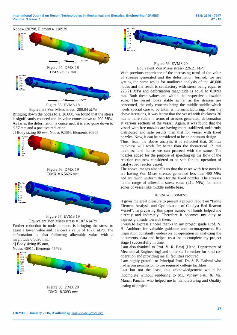
Nodes-120798, Elements- 118939
Figure 54: DMX 18
DMX - 6.57 mm
Figure 55: EVMS 18
Equivalent Von Mises stress -200.04 MPa
Bringing down the nodes to 1, 20,000, we found that the stress
is significantly reduced and its value comes down to 200 MPa.
As far as the deformation is concerned, it is also gone down to
6.57 mm and a positive reduction.
c] Body sizing 60 mm, Nodes 92384, Elements 90865
Figure 56: DMX 19
DMX = 6.5626 mm
Figure 57: EVMS 19
Equivalent Von Mises stress = 187.6 MPa
Further reduction in node numbers is bringing the stress to
again a lower value and it shows a value of 187.6 MPa. The
deformation is also following allowable value with a
magnitude 6.5626 mm.
d] Body sizing 85 mm,
Nodes 46911, Elements 45769
Figure 58: DMX 20
DMX- 8.3093 mm
Figure 59: EVMS 20
Equivalent Von Mises stress- 226.21 MPa
With previous experience of the increasing trend of the value
of stresses generated and the deformation formed, we are
getting the same result for nonlinear analysis of the 46,000
nodes and the result is satisfactory with stress being equal to
226.21 MPa and deformation magnitude is equal to 8.3093
mm. Both these values are within the respective allowable
zone. The vessel looks stable as far as the stresses are
concerned, the only concern being the middle saddle which
needs special care to be taken while manufacturing. From the
above iterations, it was learnt that the vessel with thickness 30
mm is more stable in terms of stresses generated, deformation
at various sections of the vessel. Again, it was found that the
vessel with free nozzles are having more stabilized, uniformly
distributed and safe results than that for vessel with fixed
nozzles. Now, it can be considered to be an optimum design.
Thus, from the above analysis it is reflected that, 30 mm
thickness will work far better than the theoretical 12 mm
thickness and hence we can proceed with the same. The
nozzles added for the purpose of speeding up the flow of the
reaction can now considered to be safe for the operation of
catalyst bed reactor vessel.
The above images also tells us that the cases with free nozzles
are having Von Mises stresses generated less than 400 MPa
and are much uniform than for the fixed nozzles. The stresses
in the range of allowable stress value (414 MPa) for some
zones of vessel like middle saddle base.
ACKNOWLEDGMENT
It gives me great pleasure to present a project report on “Finite
Element Analysis and Optimization of Catalyst Bed Reactor
Vessel”. In preparing this paper number of hands helped me
directly and indirectly. Therefore it becomes my duty to
express gratitude towards them.
I wish to express sincere thanks to my project guide Prof. N.
H. Ambhore for valuable guidance and encouragement. His
inspiration constantly endeavors co-operation in analyzing the
documents, data and helped us a lot to complete my project
stage I successfully in time.
I am also thankful to Prof. V. R. Bajaj (Head, Department of
Mechanical Engineering) and other staff member for kind co-
operation and providing me all facilities required.
I am highly grateful to Principal Prof. Dr. S. B. Padwal who
had given permission to use required college facilities.
Last but not the least, this acknowledgement would be
incomplete without rendering to Mr. Vinaay Patil & Mr.
Manan Panchal who helped me in manufacturing and Quality
testing of project.
Page 12
International Journal on Recent Technologies in Mechanical and Electrical Engineering (IJRMEE) ISSN: 2349 - 7947 Volume: 3 Issue: 1 07 - 18
_______________________________________________________________________________________________
18 IJRMEE | January 2016, Available @ http://www.ijrmee.org
_______________________________________________________________________________________
REFERENCES
Papers from Journal or Transactions
[1] S. Ravinder, S. Prakash, S.V. Vijay Kumar Raju, S.
Raju, P. Janaki Ramulu, “Design and Analysis of Pressure
Vessel Assembly for Testing of Missile Canister Sections
Under Differential Pressures”, Procedia Engineering,
International Conference on Design and Manufacturing,
2013, Volume 64, pp.1040–1047
[2] L. P. Anatalffy, G. A. Miller, K. D. Kirkpatrick, A. Rajguru
and Y Zhu, “Design consideration for the erection of heavy
wall and large diameter pressure vessel”, Procedia
engineering, International conference on pressure vessel
technology, 2015, pp.17-31
[3] A. Th. Diamantoudis and Th. Kermanidis, “Design by
analysis versus design by formula of high strength steel
pressure vessels: a comparative study”, International
Journal of Pressure Vessels and Piping 82, 2005, pp. 43–50
[4] Shyam R. Gupta, Chetan P. Vora, “Study of Pressure
Vessel Design and Analysis”, International Journal of
Engineering Research & Technology (IJERT), Mar-2014,
ISSN 2278-0181, Volume 3, Issue 3
[5] Bhavik Desai, “Design Automation Nozzle Reinforcement
Analysis for Pressure Vessel”, International Journal of
Innovative Research in Advanced Engineering (IJIRAE),
September 2014, ISSN 2349-2163, Volume 1, Issue 8
[6] Ming-Hsien Lu, Jiun-Shya Yu & Jien-Jong Chen, “The
effect of analysis model on the stress intensity calculation
for the nozzle attached to pressure vessel under internal
pressure loading”, International Journal of Pressure
Vessels and Piping, 2014, pp. 9-16
[7] J. S. Liu, G.T. Parks & P.J. Clarkson, “Shape optimization
of axi-symmetric cylindrical nozzles in spherical pressure
vessels subject to stress constraints”, International Journal
of Pressure Vessels and Piping, 2000, volume 78 issue 1
[8] Jerzy Lewinski, “Equivalent stress in a pressure vessel head
with a nozzle”, Journal of theoretical and applied
mechanics, 2014, 52, 4, pp. 1007-1018
[9] Usman Tariq Murtaza, M. Javed Hyder, “Optimization of
the size and shape of the set-in nozzle for a PWR reactor
pressure vessel”, Nuclear Engineering and Design 284,
2015, pp. 219–227
[10] V. N. Skopinsky, A. B. Smetankin, “Modelling and Stress
Analysis of Nozzle connections in Ellipsoidal heads of
Pressure vessels under external loading”, International
Journal of Applied Mechanics and Engineering, 2006,
Volume 11, No.4, pp. 965-979
[11] A. M. Senthil Anbazhagan, M. Dev Anand & G. Anis
Milton, “Development of Finite Element Based Wind and
Seismic Design Procedure for Horizontal Pressure vessel”,
Procedia Engineering, 2012, Volume 38, pp. 3998–4004
[12] J. Fang, Q.H. Tang & Z.F. Sang, “A comparative study of
usefulness for pad reinforcement in cylindrical vessels
under external load on nozzle”, International Journal of
Pressure Vessels and Piping 86, 2009, pp. 273–279
[13] Sudeep Zirmire, R. S. Tajane, “A Review on Butane
Separator Analysis”, International Journal of Research in
Mechanical Engineering and Technology, May -October
2014, Volume 4, Issue 2
[14] You Hong Liu, Bing-Sheng Zhang, Ming De Xue, & You
Quan Liu, “Limit pressure and design criterion of
cylindrical pressure vessels with nozzles”, International
Journal of Pressure Vessels and Piping 81, 2004, pp. 619–
624
[15] Avinash Kharat, V. V. Kulkarni, “Analysis of Stress
Concentration at Opening in Pressure Vessels using
ANOVA”, International Journal of Research in
Engineering and Technology, pISSN pp. 2321-7308
[16] Vijay Kumar and Pradeep Kumar, “Mechanical Design of
Pressure Vessel using PV-ELITE software”, International
Journal of Scientific and Research Publications, April
2014, ISSN 2250-3153, Volume 4, Issue 4
[17] Mr. Ganesh R. Mane, Prof. G. V. Shah, “FEA Based
Comparative Evaluation of Nozzles and Their Location on
Structural Performance of Pressure Vessel”, International
Journal of Emerging Trends in Engineering and
Development, June –July 2014, Issue 4, Volume 4 ISSN,
pp. 2249-6149
[18] Vishal V. Saidpatil and Prof. Arun S. Thakare, “Design &
Weight Optimization of Pressure Vessel Due to Thickness
Using Finite Element Analysis”, International Journal of
Emerging Engineering Research and Technology, June
2014, ISSN 2349-4395, Volume 2, Issue 3, PP 1-8
[19] Pravin Narale and Prof. P. S. Kachare, “Structural Analysis
of Nozzle Attachment on Pressure Vessel Design”,
International Journal of Engineering Research and
Applications (IJERA), July-August 2012, Volume 2, Issue4,
ISSN: 2248-9622, pp.1353-1358
[20] Nitin V. Titave, Dr. Satishchandra V. Joshi, Vinay Patil,
“Structural Analysis of Partitioned Vertical Column”,
International Journal of Modern Engineering Research
(IJMER), Sep.-Oct. 2012, Volume 2, Issue 5, pp. 4360-
4362
[21] Amran Ayob, Noraziah Wahi and M Kabashi Elbasheer,
“Effect of Optimum Autofrettage on Pressure Limits of
Thick-Walled Cylinder”, International Journal of
Environmental Science and Development, August 2011,
Volume 2, No. 4
Reports, Handbooks etc. [22] Pressure Vessel Engineering Ltd, Finite Element Analysis
& ASME Code Calculations Handbook, Feb-2009.
Reference Books [23] M. V. Joshi, Process Equipment Design, Macmillan
Company of India ltd, India, 1976, pp. 402-404.