FEA Information Inc. Global News & Technical Information August 2002 Dedicated to the Global Engineering Community LEAP ALTAIR-Italy ALTAIR-Western Region USA DYNAMAX ANSYS-China DYNALIS GISSETA DYNAmore FLOTREND KOSTECH ERAB THEME MFAC CAD-FEM Prof Genarro Monacelli Dr. David Benson Dr. Alexey I. Borovkov Dr. Ted Belytschko Dr. Taylan Altan Dr. Bhavin V. Mehta Prof. Ala Tabiei
Transcript
FEA Information Inc. Global News & Technical Information
August 2002
Dedicated to the Global Engineering Community
LEAP ALTAIR-Italy ALTAIR-Western Region USA
DYNAMAX ANSYS-China
DYNALIS GISSETA DYNAmore FLOTREND KOSTECH ERAB THEME MFAC CAD-FEM Prof Genarro Monacelli Dr. David Benson Dr. Alexey I. Borovkov Dr. Ted Belytschko Dr. Taylan Altan Dr. Bhavin V. Mehta Prof. Ala Tabiei
2
FEA Information Inc.
Global News &
Industry Information Volume 2 Issue 8-2002 August
Editor: Trent Eggleston Technical Writer Arthur B. Shapiro Technical Writer David Benson Graphic Designer Wayne Mindle Feature Director Marsha Victory Purpose:
The purpose of our publication is to provide technical and industry information
In This Issue:
03
A New LS-DYNA Feature for Large Deformation Modeling of Honeycomb and Form Materials – The Coupled Finite Element and Mesh-free Method
05
Ferrari 360 Modena Collaborative Commitment to the Vehicle Maker’s Art Reproduced with permission of Desktop Engineering Magazine, a Helmers Publishing Inc, publication.
10 Design of Biomedical Devices - ARA (CA) 12 Monthly Site Summary 13 FEA Participant Listing
The contents of this publication is deemed to be accurate and complete. However, FEA Information Inc. doesn’t guarantee or warrant accuracy or completeness of the material contained herein. All trademarks are the property of their respective owners. This publication is published for FEA Information Inc., Copyright 2002. All rights reserved. Not to be reproduced in hardcopy or electronic format
3
A New LS-DYNA Feature for Large Deformation Modeling of Honeycomb and Form Materials – The Coupled Finite Element and Mesh-free Method
Cheng-Tang Wu, LSTC
Structures subjected to severe material distortion commonly exist in survivability, safety and manufacturing related applications in the defense, aerospace, and automotive industries. Although the finite element formulations have been well developed in the large deformation analysis, standard finite element approaches are still ineffective in handling extreme material distortions due to severe mesh distortion. In the industrial community, this becomes one of the most challenging tasks in numerical simulations. A new LS-DYNA feature - the coupled finite element and mesh-free method is developed to minimize the mesh distortion problems encountered in the finite element method. This method is a continuum method in which the material points are associated with a local polynomial basis function, which can be used as an interpolant for field variables. The basis functions overlap other particles and meet the completeness requirement, making this method more accurate and less susceptible to distortion difficulties than finite elements. The unique features of this method include The method does not require any hourglass control or viscosity to stabilize the solution. The method does not require a regular nodal spacing in the discretization. The essential or natural boundary conditions can be directly imposed. The coupled shape functions are naturally conforming and allow the straightforward mixing of finite element and mesh-free methods in computation. This method requires a minimum human effort to add mesh-free computation into an existing finite element based analysis model. Potential applications of this method in the automotive industry include the vehicle frontal and side impact, metal parts rolling\extrusion\forging\stamping, and material cutting or riveting simulations. An example of a simulation, which involves extreme deformation and anisotropic material behavior, is the honeycomb modeling in the Leg-form impact simulation. Honeycomb materials have been widely used in deformable barriers for its energy absorbing capabilities. Usually, severe mesh tangling or excessive hourglassing are observed in the finite element analysis when the compression is over 90% as shown in Figure 1. Due to excessive mesh distortions the solid elements often invert and result in premature job terminations due to negative volume. In this example, the computation in the part with such distortions is replaced by the new method and the result does not experience mesh distortion difficulty as shown in Figure 1. Figure 2 compares the contact force-time curves predicted by the finite element method and the new method. As shown in Figure 2, the finite element result shows two peaks due to severe mesh distortion whereas the new method result shows only one narrow peak. Available low-density foam material laws for the coupled finite element and mesh-free method include the isotropic material model (MAT_LOW_DENSITY_FOAM [Mat 57] and MAT_CRUSHABLE_FOAM [Mat 63]) and the orthotropic material model (MAT_HONEYCOMB [Mat 26], and MAT_MODIFIED_HONEYCOMB [Mat 126]).
4
Figure 1. Comparison of deformation history Figure 2. Comparison of impact force
FEM
FEM +Mesh-free
Severe mesh distortion
FEM
FEM +Mesh-free
Severe mesh distortion
FEMNew method
Time (ms)
Impa
ct F
orce
(lb
f)
FEMNew method
Time (ms)
Impa
ct F
orce
(lb
f)
5
Ferrari 360 Modena Collaborative Commitment to the Vehicle Maker’s Art
Reproduced with permission of Desktop Engineering Magazine, a Helmers Publishing Inc, publication. www.deskeng.com FEA Information Inc. Participant Products showcased in this article are Livermore Software Technology Corporation’s LS-DYNA, and MSC. Software’s MSC.NASTRAN, PATRAN .
This work of art is the result of collaboration that spanned both years and continents. Charles Clarke Sadly I didn’t get to drive one of these beauties, but according to one reviewer, the new Ferrari 360 Modena is the most highly developed automotive design in the world. It is the result of years of cumulative work, evolution of previous designs, and an unprecedented collaboration on an international scale, resulting in this state-of-the-art spectacle that is coveted the world over.
The 360 is the first modern Ferrari with chassis, suspension, and body made entirely of aluminum. The Alcoa-built spaceframe, which cradles the engine, accommodates the cabin and holds the suspension, consists of Alcoa-supplied extrusions and castings. The body panels are bolted, riveted, or welded to the superstructure. The new shell is 28% lighter and more than 40% stiffer than that of the F355 (the 360’s predecessor) even though it is more than 10% larger in volume.
Figure 2: Aluminum spaceframe for the Ferrari 360 Modena.
6
The Ferrari 360 Modena features a classic spaceframe chassis design. The structural frame members are made of extruded aluminum connected by castings featuring slip joints that allow for adjustment during assembly, and also provide extra strength in areas subject to the greatest stress. The project introduces a number of innovative manufacturing and assembly technologies, which were designed specifically in conjunction with Alcoa Automotive Engineering.
The suspension mounting points on the chassis, fundamental to the car’s handling, are contained on a single casting and machined on the assembled spaceframe. This technology, already successfully introduced on the F50, allows minimum tolerances, typical of a precision mechanical part. Aluminum’s weight is 1/3 that of steel; the weight of the overall chassis was cut by 28%, in spite of a 10% increase in vehicle volume. The resulting space frame has an increased beam stiffness of 42% and a torsional rigidity of 44%, compared with the F355, which it replaces. The engineering process, backed by advanced computer simulations, led to the design of a chassis, which while lighter, meets all international passive safety requirements.
Figure 3: Sidetop detail view showing the sculpted aluminum
Figure 4: Front 3/4 view showing unmistakable Ferrari lineage.
Figure 5: Front impact simulation.
7
The spaceframe is built from multi-product components: 42% of its weight is extruded components, 33% is cast components. The remaining 25% is composed of brake-formed sheet parts and stampings. To facilitate manufacturing, extruded components are mostly straight lengths with the simple rectangular cross-sections and straight, square, or angle-end cuts. Where possible, sheet components are simple brake-formed shapes. Sand castings are used for the major structural joints. They provide significant part consolidation. Sand castings were selected over other casting technologies because of the low part volume and minimum weight requirements (minimum wall thickness is only 2.5mm and minimum draft angle less than 2%). From concept to production launch there was coordinated, continuous interaction between Ferrari and Alcoa designers and all other disciplines. Alcoa material, joining, dimensional control, and manufacturing specialists were invited to join the project team at early stages of spaceframe design and development.
Connections between extrusions and castings are predominantly MIG welded and feature staggered-lap joints developed by Alcoa. This type of structural joint provides a continuous overlap of joining components with optimized conditions for fillet welds and with extrusions having straight cut ends. Another feature of this type of joint is easy part loading and reduced joint welding gaps. CAD models of all components were developed using Unigraphics and CATIA. UG was used primarily for original component modeling and for large assemblies, welding drawings, etc. CATIA was used for line drawings and GD&T (geometric dimensioning and tolerancing) drawings. Analysis of the front and rear axial crash structures was done using LS-Dyna3D to satisfy FMVSS (Federal Motor Vehicle Safety Standards) requirements. MSC.Nastran with Patran 3 as preprocessor was used for stiffness and strength analyses
Figure 6: Example of fatigue damage prediction.
8
“The design of the spaceframe was done in Unigraphics at Alcoa in the USA with CATIA input from Ferrari in Italy," said Todd Summe, product structural engineer at Alcoa. "Ferrari had concepts before we were ever involved; these were developed on an ongoing basis in a collaborative fashion. The primary spaceframe development was done using videoconferences and phone calls." The Ferrari project had some unique challenges. "With this type of sports car, the packaging is very tight, and there were different loading conditions and constraints on the design than we were used to," said Summe. "The load requirements were much higher considering the size of the vehicle and the amount of space available for structural members." The other main challenge was to develop a frame that could be made cost effectively for low volumes and could be extended to larger volumes if necessary. On the face of it, it’s difficult to imagine ‘cost-effective’ and ‘Ferrari’ appearing in the same sentence, but like any other car maker, even Ferrari has to control costs in order to produce a viable product. "Our structural design goals were simplicity and clarity both in design and our engineering approach," said Summe. "My main responsibility was for structural design and making sure that the structure would pass all the stiffness durability and crashworthiness criteria." Alcoa’s experience allowed them to home in on potential issues quickly. "We developed reliable material fracture models to determine whether any of the parts would fracture prematurely," said Summe. "We were able to find problems by simulation very early and correct them." "We used Unigraphics to generate 3D input for LS-Dyna crash simulations," said Summe. "LS-Dyna was the primary solver for the fracture models, but we have developed our own fracture models that are not in the standard code." “The relationship between Livermore Software Technology Corp. (the authors of LS-Dyna) and Alcoa is such, with Alcoa’s access to the source code, they were able to incorporate their own fracture models into the code. "This is a very reliable and state of the art crash model," said Summe. "It has proved to be robust for very many conditions and crash scenarios."
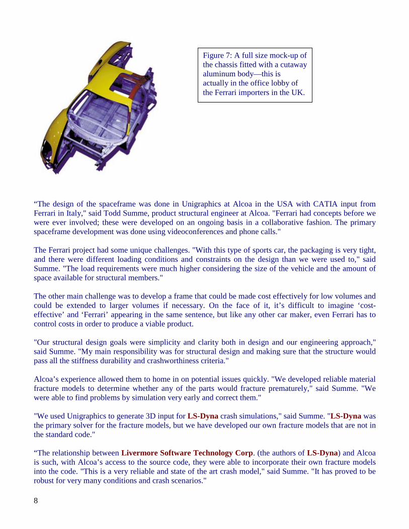
Figure 7: A full size mock-up of the chassis fitted with a cutaway aluminum body—this is actually in the office lobby of the Ferrari importers in the UK.
9
Most fracture models end up slowing solution time down dramatically, but not ours. And we have all the empirical data from our labs to test it. We’ve correlated it to simple coupon level testing, component level testing as well as full vehicle, ‘drop tower’ testing." Alcoa has also developed significant durability performance-prediction models for welded, spot-welded, and MIG-welded permanent joints based on data collected at Alcoa Technical Center over many years. "This is really a collection of guidelines and data for using tested techniques in a particular way to suit our requirements, rather than specifically developed internal software," said Summe. "We’re not developing a whole new theory in this regard, we have sufficient experience to adapt existing techniques to suit these different situations." Clearly there is formidable expertise and technology at Alcoa for the development of aluminum vehicles. The whole project was a major success in terms of collaborative engineering, not only did Alcoa and Ferrari achieve the required results, they did it on two continents separated by time zones, language, and national culture. The success of the F360 is testament to the commitment on both sides of the Atlantic to make it happen. Now, let’s talk about a test drive! Dr. Charles V. Clarke is a consultant in the manufacturing industry and writes about CAD/CAM technology. E-mail him at [email protected]..
10
DESIGN OF BIOMEDICAL DEVICES Analysis and Design of Biomedical Stents and Stent/Grafts
Courtesy of Applied Research Associates, Silicon Valley Office, Mountain View, CA For animations visit: http://www.arasvo.com/stent.htm
The design process for stents typically involves balancing conflicting mechanical requirements. For example, a compliant design that provides good radial support often leads to significant elastic recoil in deployment, a design that minimizes compaction diameter often sacrifices structural strength, a stiff design that assures secure contact with the vessel may cause damage to the vessel and restenosis. Researchers at the Silicon Valley office of ARA are developing finite element analysis software that can be used by engineers to predict the performance of stent designs.
An example finite element analysis simulates the response of a stent wire used in a stent/graft. Stresses and strains developed in the wire are calculated throughout the complete process of fabrication, deployment and service. During the interaction with the artery, stresses and deformations in the artery were calculated.
Figure 1. Calculated response of the stent wire during compaction.
These analyses are well beyond the capabilities of most available commercial finite element codes because of the high level of nonlinearity; the large deformations involved and the contacts that occurs between the wire, balloon and artery. When the wire is compacted to fit into the delivery system it experiences tight curvature due to bending, contacts with itself and twists to accommodate the small diameter of the delivery catheter.
Here we show the interaction between the the wire and the artery during deployment of the stent. This interaction is difficult to simulate because of the great differences in compliance between the stiff wire and the relatively soft artery.
11
We are developing interactive graphical user interfaces to allow designers to optimize stent designs without requiring extensive knowledge of finite element techniques. The user inputs parameters for stent geometry and materials in terms of physical quantities. This software will significantly reduce the time to market of new stent designs. It is envisioned that the design tool will incorporate all of the necessary features of a finite element code but will not require the user to have extensive knowledge of running finite element codes.
The above analyses were performed using LS-DYNA developed by the Livermore Software Technology Corporation (LSTC).
Figure 3. Graphical Interface for the stent design tool.
Figure 2. Calculated response of the stent wire during deployment.
12
FEA Information News Previously Showcased Archived on the site on the News Page
AVI Library Drop Test Toy Puppy AMD Athlon processor-based systems give users one of the highest
levels of software performance available today ANSYS ANSYS/Multiphysics™ integrates structural, thermal, CFD,
acoustic and low-/highfrequency electromagnetic simulation capabilities in one software bundle
July 01
DYNAmore Distributor located in Germany Site addition LS-DYNA MPP (page 2) to our site HPC Servers LSTC
LS-POST ver2.0 The prelude to LS-PRE-POST, this version carries forward the standard post processor functionality with added features, and now includes some pre processor functionality too.
MSC.LINUX LS-DYNA fully loaded on hardware using MSC.Linux contact
July 08
Altair - Italy Distributor located in Italy JRI
JMAG-Studio A magnetic field analysis program that supports the development and design of electrical and electronic devices such as motors, actuators, circuit components, and antennas
SGI
The SGI Origin 3000 series takes system modularity to new heights, as NUMAflexTM allows you to scale CPU, storage, and I/O components independently within each system.
July 15
Altair – Western Region
Distributor located in USA
ETA
The development of eta/VPG represents a major improvement in durability anlaysis techniques. The vehicle structure model is combined with the suspension and tire models to form the complete vehicle system model
Oasys
Bra Analysis Clothing Manufacturing Techniques analyze the stresses on clothing such as; pants, shirts, sneakers, and lingerie such as the Bra.
July 22
CAD-FEM Distributor located in Germany July 29 AVI Library Train Crash Analysis
HP hp workstation x4000 - Linux EASi EASi-CRASH® is a fully integrated package for crash simulation
which covers the CAE-process from start to finish. LEAP Located in Australia
EVENTS – see events on www.feainformation.com for details
2002 Sept 16 – 17 Sweden Nordic LS-DYNA Users’ Conference Sept. 18 & 19 USA LMS Conference for Physical and Virtual Prototyping Sept. 19&20 Germany DYNAmore – German LS-DYNA Forum Oct. 03-04 Italy Engin Soft Conference and User’s Meeting Oct. 08 UK OASYS LS-DYNA Update Meeting Oct. 09-11 Germany CAD-FEM Users Meeting - Germany Oct. 10-13 USA 10th Foresight Institute Conference on Molecular Nanotechnology Oct. 24 – 25 Japan Japanese LS-DYNA & JMAG Users Conference Oct. 28 Korea Korean LS-DYNA Users Conference
13
FEA Information Inc. Commercial & Educational Participants Headquarters Company Australia Leading Engineering Analysis Providers www.leapaust.com.au Belgium LMS, International www.lmsintl.com Canada Metal Forming Analysis Corp. www.mfac.com China ANSYS Bejing www.ansys.com (link on international) France Dynalis – Cril Technology Simulation www.criltechnology.com Germany DYNAmore www.dynamore.de Germany CAD-FEM www.cadfem.de India GissEta www.gisseta.com Italy Altair Engineering srl www.altairtorino.it Japan The Japan Research Institute, Ltd www.jri.co.jp Japan Fujitsu Ltd. www.fujitsu.com Korea THEME Engineering www.lsdyna.co.kr Korea Korean Simulation Technologies www.kostech.co.kr Russia State Unitary Enterprise - STRELA www.ls-dynarussia.com Sweden Engineering Research AB www.erab.se Taiwan Flotrend Corporation www.flotrend.com UK OASYS, Ltd www.arup.com/dyna USA Livermore Software Technology www.lstc.com USA Engineering Technology Associates www.eta.com USA ANSYS, Inc www.ansys.com USA Hewlett Packard www.hp.com USA SGI www.sgi.com USA MSC.Software www.mscsoftware.com USA EASi Engineering www.easiusa.com USA DYNAMAX www.dynamax-inc.com USA CEI www.ceintl.com USA AMD www.amd.com USA Dr. T. Belytschko Northwestern University USA Dr. D. Benson Univ. California – San Diego USA Dr. Bhavin V. Mehta Ohio University USA Dr. Taylan Altan The Ohio State U – ERC/NSM USA Prof. Ala Tabiei University of Cincinnati Russia Dr. Alexey I. Borokov St. Petersburg State Tech. University Italy Prof. Genarro Monacelli Prode – Elasis & Univ. of Napoli, Federico II