WWW.FEAINFORMATION.COM COVER STORY ANSYS ANSYS ICEM CFD ON SUPERCOMPUTER HELPS DESIGNERS 'CUT CORNERS' IN RACE CAR DESIGN TECHNICAL SPOTLIGHT AMD MULTI-CORE PROCESSORS REPRESENT A MAJOR EVOLUTION IN COMPUTING TECHNOLOGY ANALYSIS SPOTLIGHT BIRD STRIKE ON A COMPOSITE JET ENGINE INLET MAY 2005 FEA INFORMATION RESOURCE MAGAZINE INFORMATION
Transcript
W W W . F E A I N F O R M A T I O N . C O M
C O V E R S T O R Y
A N S Y S
A N S Y S I C E M C F D O N S U P E R C O M P U T E R
H E L P S D E S I G N E R S ' C U T C O R N E R S '
I N R A C E C A R D E S I G N
T E C H N I C A L S P O T L I G H T
A M D
M U L T I - C O R E P R O C E S S O R S
R E P R E S E N T A M A J O R E V O L U T I O N
I N C O M P U T I N G T E C H N O L O G Y
A N A L Y S I S S P O T L I G H T
B I R D S T R I K E O N A
C O M P O S I T E J E T
E N G I N E I N L E T
M A Y2 0 0 5
F E A I N F O R M A T I O N R E S O U R C E M A G A Z I N E
INFORMATION
FeaInformation.com 1
FEA Information Worldwide Participant’s
02 FEA Information Inc. Announcements 03 ANSYS: ANSYS ICEM CFD on Supercomputer Helps Designers
‘Cut Corners’ in Race Car Design 07 AMD: Multi-core Processors Represent a Major Evolution in Computing
Technology 11 DFE Group Meeting: A Mini-Symposium On Sheet Stamping Simulation 14 LS-DYNA SUPPORT/CUSTOMER SITES ONLINE 16 INDUSTRY NEWS Press Releases 18 CRAY: LS-DYNA Bundle on XD1 Direct From CRAY 19 May Distributor LS-DYNA Sales 20 EVENTS 21 LS-DYNA Resource Page 25 Hardware & Computing and Communication Products 26 Software Distributors 28 Consulting and Engineering Services 29 Educatonal & Contributing Participants 30 Informational Websites 31 Archived News Pages 32 LS-DYNA Bird Strike on a Composite Jet Engine Inlet 36 Top Crunch News
Editor: Trent Eggleston
Managing Editor: Marsha Victory
Technical Editor: Art Shapiro
Graphic Designer: Wayne L. Mindle
Technical Writers: Dr. David Benson Uli Franz Dr. Ala Tabiei
Technical Consultants: Steve Pilz Reza Sadeghi
Contents
FeaInformation.com 2
FEA Information Announcements Conference CD: You can sign up now for the 5th Eurpopean LS-DYNA Conference CD. There is no fee and shipping is free. Anticipated shipping is late June. www.ls-dynaconferences.com The link for the sign up form is on the side menu Information for the 2006 Conference will be posted in August
Travel:
Our news is being published a week early due to travel by Marsha Victory and Dr. Arthur Shapiro to attend the 5th European LS-DYNA Conference UK 05/25-26/05 (Arup). Please feel free to locate them and discuss articles or ideas for FEA Informational websites.
Training:
LSTC Michigan is pleased to announce the first two training courses available at their Michigan location:
Implicit LS-DYNA, May 25-27 Introduction to LS-DYNA, June 8-10 For information: Training Class Coordinator Jane Hallquist [email protected]
Sincerely, Trent Eggleston & Marsha Victory The content of this publication is deemed to be accurate and complete. However, FEA Information Inc. doesn’t guarantee or warranty accuracy or completeness of the material contained herein. All trademarks are the property of their respective owners. This pub-lication is published for FEA Information Inc., copyright 2003. All rights reserved. Not to be reproduced in hardcopy or electronic copy. Note: All reprinted full articles, excerpts, notations, and other matter are reprinted with permission and full copyright remains with the original author or company designated in the copyright notice
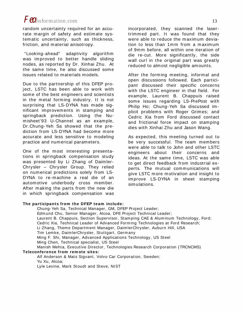
Photo showing key areas of the Pratt & Miller - General Motors C5R Cor-vette from the 2002 racing season that impact fluid flows. Challenge: Designing and engineering racecars re-quires, like anything else, prototyping and testing. Problem is, building proto-types and putting them through the nec-essary aerodynamic tests in wind tunnels can easily top $1 million. Aletheon Technologies LLC eliminated these costs and developed far more detailed data for future racecar designs. Solution: Move the aerodynamic design analyses and testing away from prototypes and wind tunnels to ANSYS® ICEM CFD as a pre- and post-processor for computa-tional fluid dynamics problems that take a supercomputer to solve. Benefits: By using CFD to optimize and balance the two key aerodynamics forces in race-downforce and drag-cars built by Aletheon's parent company, Pratt &
Miller Engineering, hug the track more tightly and corner faster. And it's in the corners that races are won and lost.
Introduction It’s not just how fast a racecar goes that makes a design a winner, it’s also how fast it goes around the curves. In large part, speed in the curves is a function of how much “downforce” is created by air flowing over the car’s surfaces. Thus much of the computational fluid dynamics (CFD) analysis of race cars has to do with making sure the airflow pushes down on the car as it does with how smoothly the car slips through the air. The major benefit of CFD in auto rac-ing: Cutting down the high costs of building prototype cars and physically testing in them in wind tunnels and on race tracks. Aletheon Technologies LLC, Mooresville, North Carolina, has long been a leader in applying CFD to racecars. Since early
FeaInformation.com 4
2002 it has been part of Pratt & Miller Engineering, New Hudson, Michigan. Pratt & Miller designs, develops, builds, racecars “from a blank sheet of paper to the victory circle” for General Motors, Ford and DaimlerChrysler, among others.
CFD models the layer of surface flow that is as thin as 0.000l inch. But with all the vortexes and friction, this flow is so complex that over 30 million points- cor-responding to degrees of freedom in conventional finite element modeling-to model an entire racecar is modeled. CFD solutions for a racecar model require the equivalent of computing’s racetrack, a supercomputer. “At the current state of development for CFD, the more points the better,” ex-plained Dr. David F. Robinson. “Compu-tationally speaking, what happens with each element effects all of its neighbors and, in fact, everything else in the model.” An alumnus of the Department of Defense CFD programs, Dr. Robinson has built his own supercomputer, nick-named Hannibal, with 210 Intel Corp. Xeon CPUs. Dr. Robinson also built his own solver, called Raven, which is marketed by Aletheon in conjunction with ANSYS CFX based in Waterloo, Ontario, Canada.
Challenge Aletheon models the entire car body-tires, wheel tubs, cockpit, underbody, shock absorbers, exhaust manifold, ra-diator-any surface that air passes over, under or through. CFD’s tedious and time-consuming grid-ding, or meshing, and its pre-processing is handled by ANSYS ICEM CFD from ANSYS, Inc.
“The main reason we model the entire car all at once instead of a single com-
ponent at a time, is due to the fully cou-pled nature of the solution,” Dr. Robin-son explained. “Since the air flow of a racecar is subsonic, information can propagate in all directions. This means changes in the rear-wing can, and often do, have strong influence on the aerody-namics of the front of the vehicle. There-fore, you cannot do an analysis of the wing independent of the other compo-nents.” The enormous files are generated be-cause every racecar surface over which air flows has to be modeled. A rule of thumb in solving models of this complex-ity is that every million data points re-quires a gigabit of RAM, hence the su-percomputer. Most other Aletheon mod-els are in the range of 250,000 to 300,000 points. If yawing is not a factor in a given analysis, the model for an en-tire car can be sliced lengthwise, halving the model to 15 million points. Solution “We put most of our CFD emphasis on improving downforce and making sure this downforce is balanced around the vehicle’s center of gravity” or CG. He emphasized, “the distribution of both drag and downforce around the CG is as important as the actual drag and down-force numbers.” The sanctioning body of a given racing series, and its insurers often limits top-end speed. “The overall aerodynamic performance envelope-drag-is strictly controlled by the sanctioning body,” he added. “We use ICEM to expand this en-velope.” An important ICEM CFD capability for Aletheon is geometry tolerance, the abil-ity to computationally ignore gaps and overlaps when gridding. This great sim-plifies and speeds up that up.
FeaInformation.com 5
Also important to Dr. Robinson is the fact that ICEM is a top-down modeler, whereas the vast majority of the others are bottom-up. “ICEM starts by putting a tetrahedral volume around the object you are modeling and then subdivides and re-subdivides the grid until you are done,” Dr. Robinson noted. “Bottom-up models require trimming all surfaces together and then laying hun-dreds of thousands of tiny triangles over these surfaces and marching them out-ward. If there is a hole or an overlap in the geometry, it cannot be ignored as with ICEM. You have to back to the CAD or solid modeler [Unigraphics, CATIA, SolidWorks or Rhino 3D], repair the ge-ometry, then re-import the new geome-try [with IGES, STEP, or the SolidWorks direct translator] and then and restart the gridding. Benefits The speed and power of ICEM lets Aletheon build better models. “ICEM lets us model directly on the CAD data rather than rebuilding the geometry model in the pre-processor,” Dr. Robinson said. “You get an accurate representation rather than an approximation. Human error is eliminated along with inaccurate interpolations for lofted curves. And ICEM helps use make sure we have all the right elements in all the right places.” Aletheon’s analyses are used mainly to cut down on wind tunnel tests and build-ing and testing prototypes. “Just to build a one-half scale model and all of the test parts needed for a year of wind tunnel tests might cost upwards of $500,000,” said Dr. Robinson. “Rent for a wind tun-nel for one day can be north of $20,000. On top of that you still need to bring in half a dozen test engineers” to set up, monitor and interpret the results.
“Wind tunnel tests give you the total drag, the drag of the airflow over the en-tire vehicle and the total downforce,” he noted. “This does not accurately simulate a race car’s operating environment unless you also model the physics of the road rolling under the car. To do this, a ‘rolling-road’ wind tunnel must be used.” In addition, to the global vehicle data provided by a wind-tunnel, CFD also pro-vides the drag and downforce of every single component, even the left rear tail-light, if you need that information. “Each CFD run may take several days, but you get significantly more data from each run,” Dr. Robinson pointed out. “The entire flowfield is captured and can be viewed using a post-processing tool. With wind tunnel testing’s global data results, this can’t be done very effec-tively. Starting the design process using CFD lets Aletheon learn enough about the problem to put bounds around the amount of additional testing that will be required. “We use CFD to narrow our choices to only those that have the high-est likelihood of improving the perform-ance of the vehicle,” he continued. “Building a prototype car costs $400,000 to $600,000,” Dr. Robinson noted. “Test-ing it means a lot of other costs” such as renting a track, expert personnel, travel, insurance, etc. Moreover, CFD analyses can be carried on while the car is being designed, long before any metal is cut or components assembled.
FeaInformation.com 6
Photo showing key areas of the Pratt & Miller - General Motors C5R Corvette from the 2002 racing season that impact fluid flows. Image courtesy of Mindfeed® Marcomm, Santa Fe, N.M.
Detail of the ICEM CFD - RAVEN compu-tation. All the relevant features have been adequately resolved. Image courtesy of Aletheon Div., Pratt & Miller, Mooresville, N.C.
The surface mesh from ANSYS ICEM CFD used for the RAVEN solver calculations. There is a very high level of fidelity in this grid. Image courtesy of Aletheon Div., Pratt & Miller, Mooresville, N.C.
FeaInformation.com 7
Multi-core Processors Represent a Major Evolution in Computing Technology. www.amd.com
Placing two or more powerful computing cores on a single processor opens up a world of important new possibilities. Learn about the evolu-tion of multi-core technology and its advantages.
The Evolution of Multi-Core Technol-ogy
With the introduction of the first com-puter came market demands for more computing capacity. Symmetrical multi-processing (SMP) has long been a tech-nology used to increase computing per-formance and efficiency by spreading computing loads across multiple proces-sors. SMP is especially effective in multi-threaded environments where many tasks (threads) need to be handled si-multaneously.
As application performance demands grow, processor designers are facing the issue that it takes more power to drive more computing capability. More power means that dissipation levels also need to be managed. Add to this the demands of the industry for computers to become smaller more servers in a rack, thin and lighter laptops, and smaller footprint for a desktop system. Multi-core processing will help address these computing chal-lenges. This evolution in technology will allow for increased performance and higher productivity in smaller computers that can simultaneously run multiple
complex applications and successfully complete more tasks in a shorter amount of time.
The Multi-Core Advantage
In today's digital world the demands of complex 3D simulations, streaming me-dia files, added levels of security, more sophisticated user interfaces, larger da-tabases, and more on-line users are be-ginning to exceed single-core processor capabilities.
Multi-core processors enable true multi-tasking. On single-core systems, multi-tasking can max out CPU utilization, re-sulting in decreased performance as op-erations have to wait to be processed. On multi-core systems, since each core has its own cache, the operating system has sufficient resources to handle most compute intensive tasks in parallel.
Multi-core technology can improve sys-tem efficiency and application perform-ance for computers running multiple ap-plications at the same time.
FeaInformation.com 8
Benefits of Multi-Core Technology
• Improved system efficiency and application performance for com-puters running multiple applica-tions
• Enhanced performance for multi-threaded applications
• Support for more users or tasks for transaction-intensive applica-tions
• Superior performance for com-pute-intensive applications
• Simplified overall computing infra-structure requirements helping to save you money
• Helps to eliminate thermal and environmental issues
AMD Multi-Core Product Benefits
The introduction of x86 multi-core tech-nology will change commercial and con-sumer computing while offering new op-portunities for software developers.
AMD believes the evolution to multi-core processors is an exciting technological advancement that will play a central role in driving relevant advancements, pro-viding greater security, resource utiliza-tion, and value for businesses and con-sumers. The client and consumer mar-kets will have access to superior per-formance and efficiency compared to single-core processors, as the next gen-eration of software applications are de-veloped to take advantage of multi-core processor technology. Consumers will now be able to experience true multi-tasking and increased performance on optimized digital media and content creation applications.
The widespread availability of hardware using multi-core processor technology
will forever change the computing uni-verse.
Commercial Benefits
Corporate IT systems currently optimized for SMP multi-threaded applications should see significant performance in-creases by using AMD multi-core proces-sors.
This logical performance boost will take place within current, available hardware and socket designs, enabling corporate IT managers to add more sophisticated system layers, like virtualization and se-curity, without significant disruption to legacy systems.
Another key benefit: Simplified manage-ability, lower TCO, and maximum proc-essor performance. The AMD Opteron™ processor with Direct Connect Architec-ture enables one platform to meet the needs of multi-tasking environments, providing platform longevity.
Consumer Benefits
AMD multi-core processors can immedi-ately benefit businesses and general consumers by providing the capability to run multimedia and security applications with increased performance.
With multi-core processors, a new era of true multitasking emerges. AMD Athlon™ 64 X2 Dual-Core processors will take computing to a new level by enabling people to simultaneously burn a CD, check e-mail, edit digital photos, and run virus protection software - all with in-creased performance. Multi-core proces-sors also will enable the growth of the digital home - now a centralized PC will
FeaInformation.com 9
be able to serve multiple rooms and people in the home.
Imagine Dad working on his finances in his office, while his son watches a movie on the living room TV that he recorded the day before to the PC, while his daughter listens to MP3s from the same PC while in her room. This will be possi-ble with the phenomenal multi-tasking capabilities that multi-core processors enable. In the commercial market, busi-nesses will realize enhanced security, improved resource utilization, and greater return on their investments in PCs.
Developer Benefits
Software professionals regularly push the limits of current processor capacity. Multi-core processors will solve many of the challenges currently facing software designers by delivering significant per-formance increases at a time when they need it most.
Multi-core processors, in combination with new compiler optimizers, will reduce compiling times by as much as 50 per-cent, giving developers a critical advan-tage in meeting time-to-market de-mands. Software vendors also can use more multi-threaded design methods for delivering enhanced features.
With the advent of multi-core processors and adoption of multi-core computer platforms by businesses and consumers, software vendors will have a much larger marketplace to distribute new and im-proved applications.
The AMD64 Multi-Core Advantage Ease of Migration to Multi-Core Proc-essors
• OEMs and system builders can easily incorporate multi-core products into their existing AMD Opteron™ processor-based and AMD Athlon™ 64 processor-based designs
• Socket infrastructure compatible with existing 90nm single-core processor architectures (Contact your solution provider to guaran-tee system readiness.)
Higher Performance Per Watt
• Customers can experience the performance advantages of multi-core processors by getting the best performance per watt avail-able in the market
Direct Connect Architecture
• For servers and workstations, the best 2-way and 4-way architecture for x86 computing
• Addresses and helps reduce the real challenges and bottlenecks of system architecture because eve-rything is directly connected to the CPU
• Directly connects the processor cores to a single die to even fur-ther reduce latencies between processors
Dual-Core Processor Overview
• AMD64 processors were designed from the start to add a second core
• Port already existed on cross-bar/SRI
• One die with 2 CPU cores, each core has its own 1MB L2 cache
FeaInformation.com 10
• Drops into existing AMD Opteron processor 940-pin sockets and AMD Athlon 64 processor 939-pin sockets that are compatible with 90nm single-core processor archi-tectures
• A BIOS update is all that is neces-sary to get a compatible system up and running with dual-core processors
• The 2 CPU cores leverage the same memory and HyperTrans-port™ technology resources avail-able in single-core processors
FeaInformation.com 11
A Mini-Symposium On Sheet Stamping Simulation
On April 25 and 26, 2005, Die Face Engi-neering Project (DFEP) held its Annual Offsite Meeting at the headquarters of Livermore Software Technology Corpora-tion (LSTC),in Livermore, California.
Dr. John O. Hallquist, president of LSTC, started the meeting with a welcome message and a thorough overview of LS-DYNA for stamping applications. DFEP team members and several LSTC engi-neers gave presentations regarding the status of stamping simulation and springback prediction and the methodol-ogy for improvements. The team mem-bers were very satisfied by LSTC’s efforts in making LS-DYNA more accurate and efficient. At the same time, they also proposed that LSTC conduct studies in several areas such as contact, element formulations, etc.
The DFEP is funded by DOE through USCAR. The main objective of the DFEP is to improve springback prediction for difficult metal parts by developing new simulation technology. Project activities are aimed at providing feedback and guidance to LSTC on enhancing existing or developing new functions to be incor-porated into LS-DYNA. Members of the
DFEP project include DaimlerChrysler (Mercedes-Benz and Chrysler), Ford, GM, Volvo Car Corporation, Alcoa, US Steel, and ThyssenKrupp Budd Company (TK-Budd). Dr. Chung-Yeh Sa of GM is the project leader and Dr. Edmund Chu of Alcoa is the technical leader of the pro-ject. Project administration is handled by TCR/NCMS.
LSTC participates as a supplier by pro-viding benchmarking, consulting, train-ing, and other technical support services to the DFEP members. With the new fea-tures and enhancements to be devel-oped, LS-DYNA will maintain its position as the industry leader in predicting springback encountered in sheet forming operations.
In his one-hour presentation titled “Metal Forming in LS-DYNA”, Dr. Hallquist gave a general introduction of LS-DYNA in metal forming simulations, with an em-phasis on element technique, contact, and recent developments. He pointed out that one of the goals for LSTC was to “combine multi-physics capabilities in a scalable code for solving highly nonlinear transient problems”, since one code can offer “huge cost savings relative to de-
FeaInformation.com 12
veloping an array of software applica-tions.” He also presented several new features which could fulfill the require-ments of some team members.
• the new keyword “*CASE” allows users to run multiple load cases sequentially in a single run;
• several new features in using local coordinate systems;
• new material models; • improvements in MPP
Dr. Hallquist provided his vision for LS-DYNA and said “LSTC is committed to providing the ‘best’ technology for sheet metal forming.” During the follow-up dis-cussion, the team members showed ap-preciation toward the efforts John and other LSTC’s engineers had spent in im-proving LS-DYNA; the participants also raised several challenging issues.
Tim Lemke from Mercedes-Benz gave a live demo on setting up a job by using LS-PrePost (LSPP) from scratch. He started the demo with an IGES file rep-resenting tool geometry. At the end, he could define everything and build an in-put deck ready for job submission com-pletely within the GUI environment. Tim has spent tremendous time in designing and testing LSPP in the last couple of years to get this capability developed. While most of the participants thought that there was still a large room for im-provement, they were surprised to see its current capability.
Brian Wainscott of LSTC reported that several bugs related to MPP had been fixed, for example, the detection and de-letion of poor elements, node release conditions, and drawbead positioning. The code also went through rigorous QA to ensure stability. He then talked about some recent improvement in mesh adap-tivity, and new features in contact.
LS-DYNA/MPP has long been used with its explicit solvers and has become the
dominant code worldwide for crash & safety simulations. Implicit solvers are also available now for the MPP versions as presented by Dr. Roger Grimes. The most important improvement in im-plicit/MPP include: a distributed memory matrix assembly and constraint applica-tion package; a distributed memory par-allel linear equation solver based on mul-tifrontal; a parallel eigensolver based on Boeing’s Lanczos software and our linear equation solver. Dr. Grimes also showed desired scalability with MPP/implicit code in springback analysis. To increase con-vergence performance in gravity loading and binder wrapping simulation, a new constraint algorithm was also imple-mented.
Dr. Yong Guo gave a detailed review of shell element formulations, and dis-cussed the advantages and disadvan-tages of each element type. Later on, he showed two new shell element formula-tions under development, which might have great potentials in improving form-ing simulation and springback prediction, especially in regions with small radius, such as in hemming, flanging simula-tions.
To seamlessly analyze a multi-stage process by using LS-DYNA, Dr. Nielen Stander presented a proposed process manager. He raised several important technical issues in designing such an in-terface, for example, file handling logis-tics, restart, recovery features, etc. He also mentioned that it is critical to inte-grate the manager with LSPP. The pro-posed manager should handle all the stamping related stages, such as gravity loading, binder wrapping, forming, trim-ming, springback, and it can run the job on different machines/platforms.
A robustness study of using LS-DYNA in stamping simulation was presented by Dr. Willem Roux of LSTC. In his study, Dr. Roux proposed a method to estimate
FeaInformation.com 13
random uncertainty required for an accu-rate margin of safety and estimate sys-tematic uncertainty, such as thickness, friction, and material anisotropy.
“Looking-ahead” adaptivity algorithm was improved to better handle sliding nodes, as reported by Dr. Xinhai Zhu. At the same time, he also discussed some issues related to materials models.
Due to the partnership of this DFEP pro-ject, LSTC has been able to work with some of the best engineers and scientists in the metal forming industry. It is not surprising that LS-DYNA has made sig-nificant improvements in stamping and springback prediction. Using the Nu-misheet’93 U-Channel as an example, Dr.Chung-Yeh Sa showed that the pre-diction from LS-DYNA had become more accurate and less sensitive to modeling practice and numerical parameters.
One of the most interesting presenta-tions in springback compensation study was presented by Li Zhang of Daimler-Chrysler – Chrysler Group. They relied on numerical predictions solely from LS-DYNA to re-machine a real die of an automotive underbody cross member. After making the parts from the new die in which springback compensation was
incorporated, they scanned the laser-trimmed part. It was found that they were able to reduce the maximum devia-tion to less than 1mm from a maximum of 9mm before, all within one iteration of die re-cut. More significantly, the side wall curl in the original part was greatly reduced to almost negligible amounts.
After the forming meeting, informal and open discussions followed. Each partici-pant discussed their specific concerns with the LSTC engineer in that field. For example, Laurent B. Chappuis raised some issues regarding LS-PrePost with Philip Ho; Chung-Yeh Sa discussed im-plicit problems with Roger Grimes; and Cedric Xia from Ford discussed contact and frictional force impact on stamping dies with Xinhai Zhu and Jason Wang.
As expected, this meeting turned out to be very successful. The team members were able to talk to John and other LSTC engineers about their concerns and ideas. At the same time, LSTC was able to get direct feedback from industrial ex-perts. The mutual communications will give LSTC more motivation and insight to improve LS-DYNA in sheet stamping simulations.
The participants from the DFEP team include:
Chung-Yeh Sa, Technical Manager, GM, DFEP Project Leader; Edmund Chu, Senior Manager, Alcoa, DFE Project Technical Leader; Laurent B. Chappuis, Section Supervisor, Stamping CAE & Aluminum Technology, Ford; Cedric Xia, Technical Leader of Advanced Forming Technologies at Ford Research; Li Zhang, Theme Department Manager, DaimlerChrysler, Auburn Hill, USA Tim Lemke, DaimlerChrysler, Stuttgart, Germany Ming F. Shi, Manager, Advanced Applications Technology, US Steel Ming Chen, Technical specialist, US Steel Manish Mehta, Executive Director, Technologies Research Corporation (TRCNCMS)
Teleconference from remote sites: Alf Anderson & Mats Sigvant, Volvo Car Corporation, Sweden; Yu Xu, Alcoa; Lyle Levine, Mark Stoudt and Steve, NIST
FeaInformation.com 14
LS-DYNA SUPPORT/CUSTOMER SITES ONLINE LS-DYNA SUPPORT
LSTC DYNAmore www.dynasupport.com A first release of the web based support database for LS-DYNA is now available online. The site gathers the knowledge of vari-ous support engineers by pro-viding answers to frequently asked questions, howto’s, tuto-rials and news related to LS-DYNA. The site will be extended and updated continuously. All information is provided by ex-perienced support engineers and double-checked by an in-ternal review process before it is published on the web. The da-tabase can be accessed via: http://www.dynasupport.com The full range of information is available free of charge. No sign-up process or password is required to access the support database. It is not the aim of the site to substitute the local hotline. The goal is rather to give detailed explanations to the customers in addition to the local distributor contacts. As a result it might help to obtain better under-standing of the features in LS-DYNA, and to facilitate a more
precise and effective exchange with the hotline. The site runs under the direction of LSTC and DYNAmore. In the near future the support site will also cover the LSTC products LS-OPT and LS-PREPOST. We would like to encourage the feedback from all LS-DYNA us-ers. So please feel free to visit our site, and let us know your opinion. Please e-mail to: [email protected] or [email protected] LS-DYNA Service & Sup-port Network CAD-FEM GmbH www.lsdyna-portal.com. The LS-DYNA Service and Support Network is a close collaboration of LS-DYNA distributors all over Europe and the world. The Network partners work together and ex-change their knowledge, such that every partner can profit from the expertise of the others. The LS-DYNA Service and Support Network has currently about 40 experienced LS-DYNA engineers. The intention of the Network is to provide our LS-DYNA customers one contact facility. Hereby the Network virtually acts as one com-
FeaInformation.com 15 pany, such that the customer has always access to the same know-how and the same people, no mat-ter where the development center is actually located. On this site we provide information on the LS-DYNA Service and Sup-port Network and general informa-tion on »LS-DYNA. In the »LS-DYNA support area you may find information on technical questions, LS-DYNA manuals as well as con-tact persons. Additionally the »LS-DYNA forum acts as the platform for LS-DYNA users to post ques-tions and answers, to exchange comments, news, tips and tricks as well as getting latest information on LS-DYNA. Soon we will present on this page a category concerning seminars, which are offered by the Network partners in the different countries all over the world. Especially we would like to encour-age students from abroad to apply for a thesis in cooperation with Network partner. So even if there is currently no specific thesis posted, we are always open for your good ideas.
FeaInformation.com 16
INDUSTRY NEWS Press Releases – SGI – AMD – NEC
The full Press Releases can be viewed on their websites. SGI: Fraunhofer-Institut IAO Accel-erates Vehicle Design at Lower Cost with Silicon Graphics Prism System
Shared Memory Visualization System De-livers Greater Visual Realism and Enables Functional Evaluation of Virtual Vehicle Prototypes
MUNICH and MOUNTAIN VIEW, Calif., (May 12, 2005)—To increase the level of realism when evaluating virtual vehicles and to accelerate its adoption by indus-try, scientists at Fraunhofer Institute for Industrial Engineering (IAO) have se-lected the Silicon Graphics Prism™ plat-form from SGI (NYSE: SGI) to solve a new class of data and rendering inten-sive problems never before possible in virtual environments. Using Virtual Drive, physical prototypes become unnecessary and test drives of many different vari-ants can be performed in the very early stages of vehicle design - reducing costs, accelerating work flows and resulting in more mature products.
The most important criteria for the choice of the Silicon Graphics Prism sys-tem was its industry-leading shared memory architecture which gives scien-tists easy-to-use, flexible high-performance deployment options. The Silicon Graphics Prism system at IAO is equipped with four graphics pipes, eight Intel® Itanium® 2 CPUs and 16GB of main memory. This system will be used to drive a 4-plane CAVE immersive envi-ronment that integrates the simulation of vehicle interiors with a classical driving
simulator. It will also be used with a Scalable Graphics Compositor to combine the rendering power of all four graphics pipes to deliver a whole new level of scene complexity and realism. The pow-erful and flexible design of Silicon Graph-ics Prism platform enables IAO to effi-ciently press ahead with its industrially oriented research activities in the area of innovative production method develop-ment…”
AMD: AMD 64 Processors Deliver World-Class 64-Bit Performance On Microsoft® Windows® x64 Platform —AMD 64 Innovative Single- and Dual-Core Processors Enable Customers to Experience Full Benefit of x86 64-bit Computing— SUNNYVALE, CALIF. -- April 25, 2005 --AMD (NYSE: AMD) today announced all existing and upcoming single- and dual-core AMD Athlon™ 64, AMD Opteron™ and AMD Turion™ 64 processors are de-signed to be fully compatible with and deliver world-class performance on Mi-crosoft® Windows® Server 2003 x64 Edi-tions and Windows XP Professional x64 Edition. “AMD is setting the 64-bit standard that the industry is embracing today and our innovative AMD64 technology, together with Microsoft’s new x64 operating sys-tems, will give millions of businesses, PC and mobile users a chance to see the power of 64-bit computing come to life,” said Marty Seyer, corporate vice presi-dent and general manager, Microproces-
FeaInformation.com 17
sor Solutions Sector, AMD. “AMD’s indus-try leadership is enabling a new set of applications and making pervasive 64-bit computing a reality. As the industry’s only x86 processor designed from the ground up for 64-bit computing and multi-core technology, AMD64 technol-ogy-powered notebooks, desktops and servers are the best choice for leveraging these two evolutionary computing ad-vances.” “While some suggested it would be im-possible to create an x86-compatible processor with competitive 64-bit and 32-bit performance, AMD plowed ahead and demonstrated it could be done,” said Nathan Brookwood, principal analyst at Insight 64. “AMD64 technology has al-tered the industry’s direction and pro-vides users with a non-disruptive path to 64-bit computing. Microsoft’s release of these x64 Windows editions provides an-other critical element needed for that 64-bit migration.”
NEC Receives Orders for Vector Su-percomputers SX-8 and SX-6 from Suzuki Motor Corporation Tokyo, April 1, 2005-- NEC Corporation ("NEC") today announced that it has re-ceived orders for two of its vector super-computers, the "SX-8/8A" (128GFLOPS peak vector performance) and "SX-6/8A" (64 GFLOPS peak vector performance), from Suzuki Motor Corporation. (GFLOPS: one billion floating-point op-erations per second) Suzuki Motor Corporation has been utiliz-ing supercomputers for development of automobile performance and simulation analysis through computer aided engi-neering ("CAE") since 1987. The com-pany is conducting more and more analyses that require large-scale simula-tion models for performance improve-ment, weight reduction, safety improve-ment, and reduction of the development period. .
FeaInformation.com 18
LS-DYNA and Cray XD1 System Bundle
*Available in North America through Cray, including paid up LS-DYNA li-cense, LS-DYNA support through LSTC, California or Michigan
*Starting price for 12 AMD Opteron™ processor single chassis system - Price includes shipping. Tax not included.
System Includes:
• 12 - 2.6 GHz AMD Opteron\031 Processors Series 200 • LS-DYNA Paid Up License • Cray HPC Enhanced Linux • 24 GB Memory • 6 - 74 GB SATA Disk Drives, 10K rpm • RapidArray Interconnect with 1.7 microsec Latency and 96 GB/sec Band-
www.figes.com Located in Bursa, Turkey – Branch offices are located in Istanbul and Ankara FIGES provides ANSYS/Multiphysics software - LSTC’s LS-DYNA, LS-PrePost, LS-OPT – ETA’s Dynaform, and other software products. Tarik Ogut - [email protected] _________________________________________________________
www.flotrend.com.tw Located in Taipei, Taiwan Flotrend provides LSTC’s LS-DYNA, LS-OPT, LS-PrePost – ETA’s ETA/VPG, ETA’s Dyna-form and other software products. Gary Chen [email protected]
www.infinite.nl Located in The Netherlands Infinite provides ANSYS, LS-DYNA, LMS Virtual Lab Jurgen Mathijssen [email protected]
FeaInformation.com 20
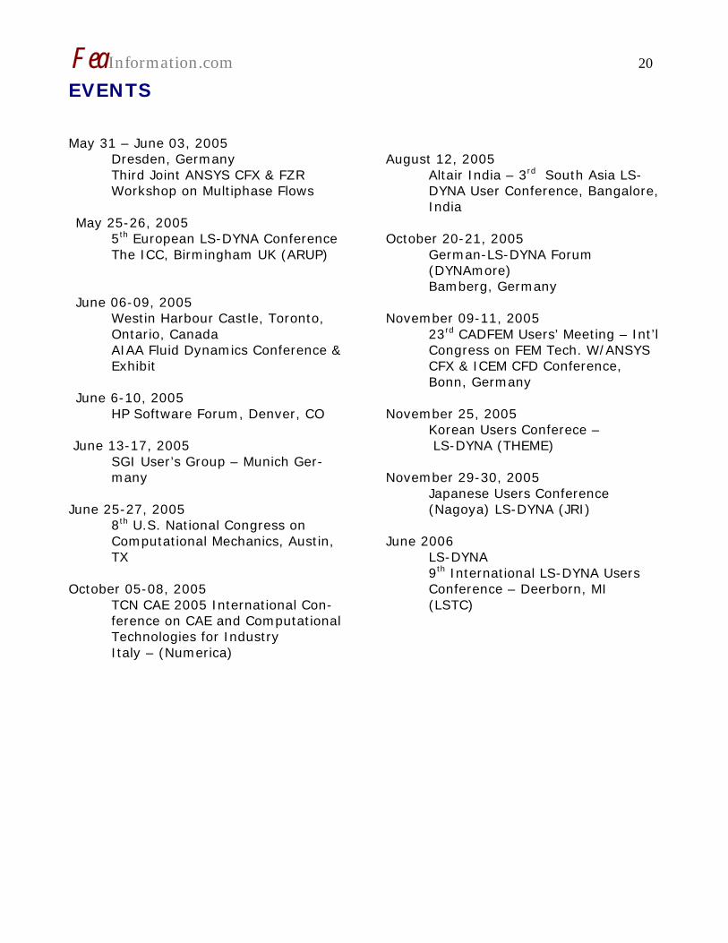
EVENTS May 31 – June 03, 2005
Dresden, Germany Third Joint ANSYS CFX & FZR Workshop on Multiphase Flows
May 25-26, 2005
5th European LS-DYNA Conference The ICC, Birmingham UK (ARUP)
Participant Hardware and OS that run LS-DYNA (alpha order)
All Hardware and OS listed have been fully QA’d by Livermore Software Technol-ogy Corporation
AMD Opteron Linux
HP PA8000 HPUX
INTEL IA32 Linux, Windows
SGI Mips IRIX6.5
CRAY XD1 Linux
HPIA64 HPUX or Linux
INTEL IA64 Linux
SGI IA64/Linux Altix/Prism
FUJITSU Prime Power SUN OS 5.8
HP Alpha True 64
INTEL Xeon EMT64 Linux
FUJITSU VPP Unix System V
IBM Power 4/5 AIX 5.1
NEC SX6 Super-UX
FeaInformation.com 22
LS-DYNA Resource Page Participant Software Interfacing or embeddingLS-DYNA
Each software program can interface to all, or a very specific and limited segment of the other software program. The following list are software programs interfacing to or hav-ing the LS-DYNA solver embedded within their product. For complete information on the software products visit the corporate website.
ANSYS/LS-DYNA - Built upon the suc-cessful ANSYS interface, ANSYS/LS-DYNA is an integrated pre and postpro-cessor for the worlds most respected ex-plicit dynamics solver, LS-DYNA. The combination makes it possible to solve combined explicit/implicit simulations in a very efficient manner, as well as per-form extensive coupled simulations in Robust Design by using mature struc-tural, thermal, electromagnetic and CFD technologies. AI*Environment: A high end pre and post processor for LS-DYNA, AI*Environment is a powerful tool for advanced modeling of complex struc-tures found in automotive, aerospace, electronic and medical fields. Solid, Shell, Beam, Fluid and Electromagnetic meshing and mesh editing tools are in-cluded under a single interface, making AI*Environement highly capable, yet easy to use for advanced modeling needs. ETA – DYNAFORM www.eta.com
Includes a complete CAD interface capa-ble of importing, modeling and analyz-ing, any die design. Available for PC, LINUX and UNIX, DYNAFORM couples af-
fordable software with today's high-end, low-cost hardware for a complete and affordable metal forming solution.
ETA – VPG www.eta.com
Streamlined CAE software package pro-vides an event-based simulation solution of nonlinear, dynamic problems. eta/VPG's single software package over-comes the limitations of existing CAE analysis methods. It is designed to ana-lyze the behavior of mechanical and structural systems as simple as linkages, and as complex as full vehicles
Tightly-integrated solution that combines MSC.Dytran's advanced fluid-structure interaction capabilities with LS-DYNA's high-performance structural DMP within a common simulation environment. In-novative explicit nonlinear technology enables extreme, short-duration dynamic events to be simulated for a variety of industrial and commercial applications on UNIX, Linux, and Windows platforms. Joint solution can also be used in con-junction with a full suite of Virtual Prod-uct Development tools via a flexible,
FeaInformation.com 23
cost-effective MSC.MasterKey License System. Side Impact With Fuel Oil Inside MSC.Software - MSC.Nastran/SOL 700 The MSC.NastranTM Explicit Nonlinear product module (SOL 700) provides MSC.Nastran users the ability access the explicit nonlinear structural simulation capabilities of the MSC.Dytran LS-DYNA solver using the MSC.Nastran Bulk Data input format. This product module offers unprecedented capabilities to analyze a variety of problems involving short dura-tion, highly dynamic events with severe geometric and material nonlinearities. cMSC.Nastran Explicit Nonlinear will al-low users to work within one common modeling environment using the same Bulk Data interface. NVH, linear, and nonlinear models can be used for explicit applications such as crash, crush, and drop test simulations. This reduces the time required to build additional models for another analysis programs, lowers risk due to information transfer or trans-
lation issues, and eliminates the need for additional software training. The MSC.Nastran Sol 700 will be re-leased in November 2005. Beta release is available now ! MSC.Software – Gateway for LS-DYNA Gateway for LS-DYNA provides you with the ability to access basic LS-DYNA simulation capabilities in a fully inte-grated and generative way. Accessed via a specific Crash workbench on the GPS workspace, the application enhances CATIA V5 to allow finite element analysis models to be output to LS-DYNA and then results to be displayed back in CATIA. Gateway for LS-DYNA supports explicit nonlinear analysis such as crash, drop test, and rigid wall analysis.
Gateway products provide CATIA V5 us-ers with the ability to directly interface with their existing corporate simulation resources, and exchange and archive as-sociated simulation data.
FeaInformation.com 24
Oasys software for LS-DYNA www.arup.com/dyna
Oasys software is custom-written for 100% compatibility with LS-DYNA. Oasys PRIMER offers model creation, editing and error removal, together with many specialist functions for rapid generation of error-free models. Oasys also offer post-processing software for in-depth analysis of results and automatic report generation.
LS-DYNA Events
UK 05/25-26/05 (Arup) 5th European LS-DYNA Conference
INDIA 08/12 (Altair India) 3rd South Asia LS-DYNA User Conference,
Italy 10/05-10/06 (Numerica) (Numerica) TCN CAE 2005 International Conference on CAE and Computational Technologies for Industry - workshops focusing on LS-DYNA
Germany - 10/20-10/21 (DYNAmore) German LS-DYNA Forum
Germany - 11/09-11/11 (CADFEM) Int'l Congress on FEM Tech.. workshops focusing on LS-DYNA
Korea 11/25/05 (THEME) Korean LS-DYNA Users Conference
Japan 11/29-30/05 (JRI) Japanese LS-DYNA Users Conference (Nagoya)
US 06/06 (LSTC) 9th International LS-DYNA Users Conference
FeaInformation.com 25
Hardware & Computing and Communication Products
www.amd.com
www.fujitsu.com
www.hp.com
www-1.ibm.com/servers/deepcomputing
www.intel.com
www.nec.com
www.sgi.com
www.cray.com
FeaInformation.com 26
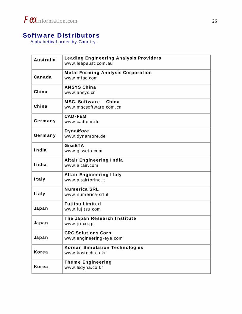
Software Distributors Alphabetical order by Country
Australia
Leading Engineering Analysis Providers www.leapaust.com.au
Canada Metal Forming Analysis Corporation www.mfac.com
China ANSYS China www.ansys.cn
China MSC. Software – China www.mscsoftware.com.cn
Educational & Contributing Participants Alphabetical Order By Country China
Dr. Quing Zhou Tsinghua University
India
Dr. Anindya Deb Indian Institute of Science
Italy
Professor Gennaro Monacelli
Prode – Elasis & Univ. of Napoli, Frederico II
Russia Dr. Alexey I. Borovkov St. Petersburg State Tech. University
USA Dr. Ted Belytschko Northwestern University
USA Dr. David Benson University of California – San Diego
USA Dr. Bhavin V. Mehta Ohio University
USA Dr. Taylan Altan The Ohio State U – ERC/NSM
USA Dr. Ala Tabiei University of Cincinnati
USA Tony Taylor Irvin Aerospace Inc.
FeaInformation.com 30
Informational Websites
FEA Informationwebsites
www.feainformation.com
TopCrunch – Benchmarks
www.topcrunch.org
LS-DYNA Support Site LSTC & DYNAmore
www.dynasupport.com
LS-DYNA Examples (more than 100 Examples)
www.dynaexamples.com
LS-DYNA Conference Site
www.ls-dynaconferences.com
LS-DYNA Publications to Download On Line
www.dynalook.com
LS-DYNA Publications
www.feapublications.com
LS-DYNA CADFEM Portal
www.lsdyna-portal.com.
FeaInformation.com 31
Archived News Page April 2005 April 4th
MSC.Dytran: Execute LS-DYNA from inside MSC. Dytran. GISSETA – Distributor in India
April 11th
JRI: The Japan Research Insti-tute, Limited (JRI) offers the fol-lowing services as a distributor of LS-DYNA in Japan and a developer of CAE package software: Flotrend - Distributor in Taiwan
April 18th
ETA: eta/VPG (Virtual Proving Ground) is a revolutionary new systems analysis software package. KOSTECH - Distributor in KOREA
April 25th
The HP 9000 server family Intel® Extended Memory 64 Technology DYNAmore - Distributor in Ger-many
FeaInformation.com 32
Bird Strike on a Composite Jet Engine Inlet
Work conducted by: Sergey Kukanov and Dimitry Roschikhmarov SAROV LABS
Goals of the project The interest of the Aerospace Working Group is to have a representative simulation for a bird strike on a composite jet engine inlet as a starting point for further work. This simu-lation also serves as an Aerospace Quality Assurance Benchmark that LSTC is putting in place in order to provide consistency in results among computer platforms and versions of LS-DYNA. Both a Lagrangian and an ALE (Arbitrary Lagrangian Eulerian) simulation were performed. Units Units are (mass, length, time, force, stress, energy) lbf-s2/in, in, s, lbf, psi, lbf-in unless otherwise specified. Composite Inlet Section: The inlet section was modeled using *MAT_LAMINATED_COMPOSITE_FABRIC. The mate-rial data does not directly represent any actual material in use in the aerospace industry, but are “good enough” for the purpose of this work. The material erodes at 0.5 effective strain. Twelve equally-spaced integration points through the thickness were used. *MAT_LAMINATED_COMPOSITE_FABRIC $# mid ro ea eb (ec) prba tau1 gamma1 1 1.4400E-4 6.5300E+6 6.6100E+6 6.5300E+6 0.290000 0.0 0.0 $# gab gbc gca slimt1 slimc1 slimt2 slimc2 slims 2.5800E+6 2.5600E+6 7.0000E+5 1.000000 1.000000 1.000000 1.000000 1.000000 $# aopt tsize erods soft fs 0.0 0.0 0.500000 0.3 1.000000 $# xp yp zp a1 a2 a3 0.0 0.0 0.0 0.0 0.0 0.0 $# v1 v2 v3 d1 d2 d3 beta 0.0 0.0 0.0 0.0 0.0 0.0 0.0 $# e11c e11t e22c e22t gms 0.026000 0.034000 0.019800 0.024000 0.024000 $# xc xt yc yt sc 147000.000 2.3340E+5 122400.00 132200.00 30000.000
FeaInformation.com 33
Figure: A close up of the inlet section. The inlet section was modeled with 2 alternating parts. This was done so that the different parts would refer to alternate integration rules that represent the weave of the composite
Bird Material Properties
The bird was modeled with an ellipsoidal shape (10in x 5 in by 5 in), a weight of 9 pounds, and material properties similar to water. The *MAT_NULL and *EOS_GRUNEISEN were used for the material constitutive model. *MAT_NULL $# mid ro pc mu terod cerod ym pr 910000 1.8100E-4 -0.001000 2.0000E-7 0.000 0.000 0.000 0.000 *EOS_GRUNEISEN $# eosid c s1 s2 s3 gamao a e0 910000 58267.000 2.560000 -1.986000 0.226800 0.500000 0.000 0.000 $# v0 0.000
Lagrangian Bird Model The Lagrangian bird was translated to contact the engine inlet. The contact was defined using the *CONTACT_ERODING_SURFACE_TO_SURFACE keyword. Once contact takes place most of the bird elements get highly distorted and the following keyword permits the erosion of these elements. A criterion based on the equivalent effective strain was used. *MAT_ADD_EROSION $# mid excl 910000 1234.0000 $# pfail sigp1 sigvm epsp1 epssh sigth impulse failtm 1234.0000 1234.0000 1234.0000 0.550000 1234.0000 1234.0000 1234.0000 1234.0000
The hourglass coefficient QM was lowered to 1.0E-04 in order to reduce the amount of hourglass energy that is produced. ALE Bird Model The ALE bird was defined within the Eulerian mesh by means of a geometric surface as shown in the following figure.
FeaInformation.com 34
The ALE mesh was translated to contact the Lagrangian engine inlet using the *ALE_REFERNCE_SYSTEM_GROUP keyword. The contact between bird and the compos-ite inlet is enforced using the *CONSTRAINED_LAGRANGE_IN_SOLID keyword. We changed the default coupling type to penalty with erosion (CTYPE=4), since it showed better energy conservation. The hourglass coefficient QM was lowered to 1.0E-06 to re-duce the amount of hourglass energy that is produced.
Lagrangian and ALE Simulation Results The following sequence of snapshots show the deformed geometry for the ALE simulation (left) and the Lagrangian simulation (right)
FeaInformation.com 35
The following figure shows the deformation of the composite inlet section. Shown are fringes of the damage parameter ω1 for *MAT_LAMINATED_COMPOSITE_FABRIC.
FeaInformation.com 36
TOP CRUNCH NEWS Dr. David Benson www.topcrunch.org Ting-Ting Zhu at CRAY Inc., has provided Top Crunch with benchmark performances on the 3 Vehicle Collision for the CRAY XD1 The LS-DYNA MPP970, Version 970/Rev 5434a Processor: AMD Opteron 2.4 GHZ The input file along with the instructions on running it, are available on the download page of Top Crunch. Visitors to the site can plot the performance of any of the machines that have been benchmarked on the site.