Calhoun: The NPS Institutional Archive Theses and Dissertations Thesis Collection 1993-12 Feasibility analysis of using microcircuit technology in logistics applications/radio frequency (MITLA/RF) to support equipment maintenance management Amirante, Robert V. Monterey, California. Naval Postgraduate School http://hdl.handle.net/10945/39655
Transcript
Calhoun: The NPS Institutional Archive
Theses and Dissertations Thesis Collection
1993-12
Feasibility analysis of using microcircuit technology
in logistics applications/radio frequency (MITLA/RF)
to support equipment maintenance management
Amirante, Robert V.
Monterey, California. Naval Postgraduate School
http://hdl.handle.net/10945/39655
NAVAL POSTGRADUATE SCHOOLMonterey, California
DTICMA•R 1. ",Ce4
THESIS
FEASIBILITY ANALYSIS OF USING MICROCIRCUITTECHNOLOGY IN LOGISTICS APPLICATIONS/RADIOFREQUENCY (MITLA/RF) TO SUPPORT EQUIPMENT
Approved for public release; distribution is unlimited.
- 94-09122
V4 3 22 026
REPORT DOCUMENTATION PAGE Form Approved OMB No. 0704
Public reporting burden for this collection of information is estimated to average I hour per response, including the time for reviewing instruction,searching existing data sources, gathering and maintaining the data needed. and compklting and reviewing the collection of information. Send commentsregarding this burden estimate or any other aspect of this collection of information, including suggestions for reducing this burden, to WashingtonHeadquarters Services, Directorate for Information Operations and Reports, 1215 Jefferson Davis Highway, Suite 1204, Arlington, VA 22202-4302, andto the Offi.e of Management and Budget, Paperwork Reduction Project (0704-0119) Washington DC 20503.
1. AGENCY USE ONLY (Leave blank) 2. REPORT DATE 3. REPORT TYPE AND DATES COVERED
December, 1993 Master's Thesis
4. TITLE AND SUBTITLE FEASIBILITY ANALYSIS OF USING 5. FUNDING NUMBERS
MICROCIRCUIT TECHNOLOGY IN LOGISTICS APPLI-CATIONS/RADIO FREQUENCY (MITLA/RF) IN SUPPORTOF EQUIPMENT MAINTENANCE MANAGEMENT
6. AUTHOR(S) Amirante, Robert V. and Baker, Greggory L.
7. PERFORMING ORGANIZATION NAME(S) AND ADDRESS(ES) 8. PERFORMING
Naval Postgraduate School ORGANIZATION
Monterey CA 93943-5000 REPORT NUMBER
9. SPONSORING/MONITORING AGENCY NAME(S) AND ADDRESS(ES) 10. SPONSORING/MONITORINGAGENCY REPORT NUMBER
1I. SUPPLEMENTARY NOTES The views expressed in this thesis are those of the author and do notreflect the official policy or position of the Department of Defense or the U.S. Government.
12a. DISTRIBUTION/AVAILABILITY STATEMENT 12b. DISTRIBUTION CODE
Approved for public release; distribution is unlimited. A
13. ABSTRACT (marimum 200 wondi)
This thesis presents the background, criteria, and baseline recommendations for a Microcircuit Technologyin Logistics Application/Radio Frequency (MITLA/RF) proposal to support developing maintenancemanagement doctrine. Its main thrust is a preliminary feasibility analysis of MITLA/RF to identify keyissues with regard to maintenance operations within emerging Operational Maneuver From The Sea(OMFTS) concepts. This thesis surveys current requirements, information systems initiatives, test/evaluationresults, implementation issues, and technology tradeoffs. It offers alternatives to reliance on manual recordkeeping and frameworks for enhancing horizontal/vertical information flows, explores several near real-timeinteractive decision making tools, and suggests doctrinal improvements through a fusion of procedural andhigh-tech approaches. This study is an outline for melding policy change with the state-of-the-arttechnology required to successfully support emerging Combat Service Support (CSS) operations.
14. SUBJECT TERMS MITLA/RF, LOGAIS, Maintenance Management, 15. NUMBER OF
17. SECURITY CLASSIFI- 18. SECURITY CLASSIFI- 19. SECURITY CLASSIFI- 20. LIMITATION OFCATION OF REPORT CATION OF THIS PAGE CATION OF ABSTRACT ABSTRACTUnclassified Unclassified Unclassified UL
NSN 7540-01-280-5500 Standard Form 298 (Rev. 2-89)Prescribed by ANSI Std. 239-18
Approved for public release; distribution is unlimited.
FEASIBILITY ANALYSIS OF USING MICROCIRCUIT TECHNOLOGY IN LOGISTICS
APPLICATIONS/RADIO FREQUENCY (MITLA/RF) TO SUPPORT EQUIPMENT
MAINTENANCE MANAGEMENT
by
Robert V. AmiranteMajor, United States Marine Corps
B.A., George Williams College
and
Greggory L. BakerCaptain, United States Marine Corps
B.A., University of Florida
Submitted in partial fulfillment
of the requirements for the degree of
MASTER OF SCIENCE IN MANAGEMENT
from the
NAVAL POSTGRADUATE SCHOOL
December 1993
Robert V. Amirante
Approved by:
effrey Ne els, Thesi o-Advisor
Dav . hi anDepartment of AdministratiS
ABSTRACT
This thesis presents the background, criteria, and baseline recom-
mendations for a Microcircuit Technology in Logistics Application/Radio
Frequency (MITLA/RF) pr-posal to support developing maintenance management
doctrine. Its main thrust is a preliminary feasibility analysis of
MITLA/RF to identify key issues with regard to maintenance operations
within emerging Operational Maneuver From The Sea (OMFTS) concepts. This
thesis surveys current requirements, information systems initiatives,
test/evaluation results, implementation issues, and technology tradeoffs.
It offers alternatives to reliance on manual record keeping and frameworks
for enhancing horizontal/vertical information flows, explores several near
real-time interactive decision making tools, and suggests doctrinal
improvements through a fusion of procedural and high-tech approaches.
This study is an outline for melding policy change with the state-of-the-
art technology required to successfully support emerging Combat Service
Support (CSS) operations.
Accesion For
DIHC " .AI'N'TiZS CP'>.
B y ... .... .. .... .... . ........
iii
ACKNOWLEDGEMENTS
In any undertaking requiring special dedication, thereare those upon whom one must depend, no matter how individualthe effort. Rob Reis, President, Savi Technology; MajorLundgren, MITLA Coordinating Group, HQMC; and Major Pontani,Maintenance Management Office, HQMC; generously gave of theirtime and provided background material which we invariably usedas a foundation for this thesis.
We want to thank Ken Michon, Lynn Torres, and SteveGundersen, Naval Facilities Engineering Service Center, forspirited support and permission to use and/or revise materialfrom their many technical documents; and Lieutenant MarnDyson, an outstanding colleague who kept us from makingeditorial errors. We, however, are responsible for errors offact and theory.
But above all, we want to add a special thanks to ourthesis advisors, Professor Keebom Kang and LieutenantCommander Jeffrey Nevels. They served in a variety of roles:counselors, critics, and proofreaders - their professionalismwas matched only by their enthusiasm and good humor.
iv
TABLE OF CONTENTS
I. INTRODUCTION .................. ................... 1
A. OVERVIEW ........... .................. I
B. RESEARCH OBJECTIVES ............ ............. 7
C. SCOPE, LIMITATIONS, AND ASSUMPTIONS ... ..... 8
1. Scope ................ ................. 8
2. Limitations ............. .............. 9
3. Assumptions ............. .............. 9
D. METHODOLOGY ................ ................. 9
E. THESIS ORGANIZATION ...... ............. .. 11
II. OVERVIEW OF MAINTENANCE MANAGEMENT AND AIT . . 13
A. GENERAL ............ ................... .. 13
B. MAINTENANCE MANAGEMENT ..... ........... .. 14
1. Levels of Maintenance ... ......... .. 15
2. Maintenance Production Functions . . .. 17
3. USMC Maintenance Program ... ........ .. 18
C. MODIFICATION AND PREVENTIVE MAINTENANCE . . 21
1. Modification Control Records ........ .. 22
2. Preventive Maintenance Rosters ..... .. 23
3. Strategic Shortcomings ... ......... .. 25
D. AUTOMATIC IDENTIFICATION TECHNOLOGY ..... .. 27
1. Barcoding/Softstrip Systems ...... .. 29
2. Optical Character Recognition (OCR) . 30
v
3. MITLA . . . . . . . . . . . . . . . . . 32
a. Contact Systems .... .......... .. 34
(1) Smart Card .... .......... .. 35
(2) Laser Cards/Optical Systems 36
(3) Magnetic Stripe .. ....... .. 39
b. Noncontact Systems .. ........ .. 40
(1) Infrared ........ ........... 41
(2) Radio Frequency .. ....... .. 42
4. Speech Recognition .... ........... .. 45
5. Artificial Intelligence .. ........ .. 46
E. TECHNOLOGY CONSTRAINTS ..................... 49
III. MITLA RADIO FREQUENCY IDENTIFICATION ......... .. 53
A. GENERAL ............ ................... .. 53
B. PROMISING TECHNOLOGIES ..... ........... .. 54
C. DESCRIPTION OF RFID TECHNOLOGY .. ....... .. 57
D. FLEET OPERATIONAL NEED STATEMENT (FONS) 60
1. Desired Characteristics .. ........ .. 61
2. System Architecture Requirements .... 62
3. Support Requirements .... .......... .. 64
E. USMC INITIATIVES ....... .............. .. 64
1. SAVI R&D Effort ..... ............ 65
2. Description of SAVI Tag Technology . 66
F. VIABLE MITLA/RF APPLICATIONS .. ........ .. 69
vi
IV. INTEGRATION STRATEGIES .............. 72
A. GENERAL ............ ................... .. 72
B. EXISTING TECHNOLOGY AND PROCESS FLOW . . .. 73
C. OPERATIONAL CONCEPT ...... ............. .. 77
D. MITLA/RF SYSTEM DATABASE ... .......... .. 78
E. SYSTEM INTERFACES ...... .............. .. 81
F. A MAINTENANCE MANAGEMENT "GAME PLAN" . . . . 83
V. CONCLUSION, RECOMMENDATIONS, AND FINAL REMARKS 87
A. GENERAL ............ ................... .. 87
B. CONCLUSION AND RECOMMENDATIONS .. ....... .. 88
C. FINAL REMARKS ........ ................ .. 94
APPENDIX A (List of Abbreviations) ... .......... 98
APPENDIX B (List of Key Terms) ....... ............ 102
APPENDIX C (Modification Control Records) ......... .. 106
APPENDIX D (Preventive Maintenance Roster) .. ...... 108
APPENDIX E (TyTag System Components) ... ......... 109
APPENDIX F (System Component Descriptions) ..... ...... 110
APPENDIX G (MITLA/RF Survey) ....... ............. 117
vii
LIST OF REFERENCES ................................... 119
INITIAL DISTRIBUTION LIST ........ ............... 126
viii
I. INTRODUCTION
A. OVERVIEW
As stated clearly in From the Sea," a Navy and
Marine Corps White Paper that articulates the new direction
for the Naval Service, the Navy and Marine Corps team will
provide the nation's Naval expeditionary forces - shaped for
joint operations - operating forward from the sea - tailored
for national needs. This new direction for the Naval service
means that the Marine Corps must continue to improve its rapid
response capability. The primary objectives outlined in
Marine Corps' Exploratory Development Program FY 1993 Block
Plan contribute to this goal. Specifically, the focus of this
Block is to develop/demonstrate technologies to meet the
Marine Corps' unique responsibility for expeditionary mis-
sions, amphibious warfare, and subsequent operations ashore.
Expeditionary operations, amphibious in nature, place a
premium on mobility, command and control responsiveness, and
global (near real-time) communications.
Combat Service Support (CSS), as currently defined, is
not optimally designed to sustain combat elements where
increased operational tempo, mobility, and over-the-horizon
maneuver warfare have outraced the development of logistic
systems. Accordingly, we need to redefine Combat Service
1
Support concepts and identify ways to improve Marine Air
Ground Task Force (MAGTF) 2perational effectiveness through:
* Reducing labor re7uirements
* Expanding the flexibility of CSS operations
* Providing near-real time, worldwide access to data
* Enhancing the capability inherent in the CSS concept
* Using current hardware and software to the maximum extentpossible
* Developing/demonstrating technologies that will allow CSSorganizations to support emerging MAGTF operational ideasbeyond the year 2010
* Providing these capabilities to the Fleet Marine Forcewith the least risk and maximum timeliness
New technologies are required to quickly process unprece-
dented quantities of CSS data to support the logistics aspects
of emerging command and control concepts. Experience during
Operaticon Desert Storm serves as a valuable object lesson for
the need for automated systems to support Marine Corps
operations. The potential utility of a deployable system that
locates assets and updates CSS systems with a minimum of labor
is unlimited. Regional Information Systems Management Offices
(ISMO) and logistics personnel developed ad hoc database
programs during the operation; these were simple and quick
attempts to manage overwhelming problems. Although providing
only crude data processing support, they proved to be tremen-
dously useful in managing the substantial volume of data.
2
These limited successes suggest that proper application of
technology and systems integration would greatly affect the
Marine Corps' capability to perform its missions.
Several CSS functions will require new or substantially
improved data processing capability. Decision making,
hindered by disjointed, incomplete, and cumbersome re-
cords/forms/messages, can no longer be tolerated. The ability
to locate and use information regarding such key ideas as
equipment maintenance posture (operational availability) and
periodic maintenance/combat repair are prime examples of CSS
functions that must embrace developing technologies.
Currently, equipment maintenance management is a labor
intensive paper and menu-driven process that receives little
attention during contingency scenarios - exactly when this
information and CSS flexibility are most critical. The
various automated "systems" locally developed by Marine Corps
activities to track some limited maintenance functions are not
standardized, often insupportable, lack connectivity, and
result in essentially manual systems without paper. For
maintenance support to be responsive, new technologies are
needed to enhance horizontal/vertical information flow and to
provide interactive decision making tools.
3
To track maintenance management, two levels of the CSS
system are fundamental. The first level is oriented toward a
global perspective, where Fleet Marine Forces (FMF) are
concerned with equipment requirements, locations, and their
operational availability. The second level is a local view
including battalion maintenance commodities, Combat Service
Support Elements (CSSE), Arrival and Assembly Support Parties
(AASP), or Logistics Movement Control Centers (LMCC) where
tracking equipment in marshalling areas and maintenance
activities is a key objective. A global view requires
periodic updates of information, often within hours. A local
view requires near real-time flow of information, often within
minutes. The appropriate integration of systems and technol-
ogies will meld these levels, streamlining equipment mainte-
nance management procedures and improving Marine Corps
readiness.
Solving the problem of the need for fully automated, near
real-time data will require systems that involve developing
and integrating emerging technologies such as: (1) micro chips
(smart tags), (2) extremely small, low power, long shelf-life
batteries, (3) technologies for transmitting data over-the-
horizon, and (4) new electronic methods to query, queue, and
receive data from smart technology.' New information manage-
' Their "intelligence" stems from concepts that envisiontheir communicating with future logistics systems, knowingwhere they are, and self-diagnostic maintenance status.
4
ment approaches must meet the technical challenges of adapting
to greatly expanded volumes of data and wide area networking
in a wireless environment, particularly when data transfer
must be secure.
To execute sound and timely decisions, commanding
officers and maintenance officers require accuiate, consistent
data about equipment status. The first step in this informa-
tion gathering proc'- is to actively monitor equipment
maintenance management. Recent advances in data-recording
technology offer the opportunity to examine ways to improve
existing manual systems that are error-prone, rely on "hard
copy" documentation, and require repetitive data entry. An
automatic identification system will facilitate decision
making and improve data collection precision, while decreasing
the costs associated with gathering and maintaining such data.
The Department of Defense (DOD), during the past several
years, has been conducting a program to reduce the generation
of and reliance on manually-prepared technical documentation.
The emphasis has been placed on exploiting advances in many
forms of automation technology to reach this objective.
Several initiatives show promise of significantly reducing the
paperwork and menu-driven keystrokes now associated with our
logistics operations. If adopted, such modernization and
automation will result in better support to the operating
5
forces. Barcoding and smart tags [contact/near contact and
radio frequency (RF)] are indicative of these advancements.
The emergence of microchip tags employing radio carrier
waves to receive/transmit data is just beginning to be recog-
nized as a promising logistics tool. Specifically, micro-
circuit technology has come to the forefront in recent years
as a relief from the burdens of manual record keeping.
Additionally, it is a value-added concept that allows for
intelligent, near real-time communications. It offers the
advantage of recording and storing data reliably and elimi-
nates the need to enter the same data time and again. As with
other recent advances in data handling, commercially available
(off-the-shelf) RF microchip technology is a prime candidate
for reducing labor intensity and compartmentalized logistics
functions. It is this innovative concept, known as "Micro-
circuit Technology in Logistics Applications/Radio Frequency
(MITLA/RF)," which is addressed by this treatise.
This thesis examines the background, requirements, and
baseline recommendations for maintenance management MITLA/RF
initiatives. If adopted, such Recording and Tracking Technol-
ogies (RTT) will result in an integrated system of computer-
aided tools for logistics data processing, information
presentation, planning development, and wide-area data
transfer to satisfy command and control requirements.
6
Developing this system allows rapid identification of equip-
ment availability and maintenance status, full automation of
the maintenance management process, and informed, strategic
decision making. In short, this system will provide CSS the
firepower required to support Operational Maneuver From The
Sea (OMFTS) as envisioned beyond the year 2010.
B. RESEARCH OBJECTIVES
The main objective of this thesis is to answer the
primary question, "What is the potential for MITLA/RF to
enhance USMC equipment maintenance management operations and
to significantly improve force preparedness?" Efforts will
focus on the following elements:
* Can it provide near real-time data access?
* What are potential labor and data management savings?
* Will it integrate with and capitalize on existinghardware/software systems?
* Is it compatible with hazardous materials (i.e., ammuni-tion, explosives, fuels, etc.)?
*To what extent will it speed front-end processing ofroutine maintenance management transactions?
4 How well suited is it to storing and reflecting themaintenance status of principal end-items (PEI)?
*Is the application technically feasible and available tosatisfy maintenance requirements? For example:
"£ Speed - read/write throughput
"£ Capacity - initial and future needs
"£ Programmability - read only or read/write
"£ Service Life - ruggedness and battery life
7
A Range - reliability as a function of distance
a Reliability - percentage of correct reads and up-timeas a function of component failure
C. SCOPE, LIMITATIONS, AND ASSUMPTIONS
1. Scope
The main thrust of this study is a preliminary
feasibility analysis of MITLA/RF to identify key issues
concerning potential application with specific regard to
equipment modification and general maintenance management
operations. This thesis surveys: (1) current requirements,
material management, (4) provisioning and acquisition of
MITLA/RF and logistic support elements, (5) market analysis,
(6) system maintenance concepts, and (7) system retirement and
recycling.
8
2. Limitations
The breadth of this study has been constrained by
several factors:
4 Limited access to substantial "real world" data
* No USMC baseline for aggregate labor hours/costs expendedin managing equipment maintenance programs
*Inability to measure tangible value of MITLA/RF tosupport maintenance operations (i.e., forms/recordq nottranslated into supportive software, hardware unavailablefor testing, controlled environment to weigh tradeoffsbetween status quo and emerging technologies, etc.)
3. Assumptions
As technology expands and requirements change, the
Marine Corps must have an automated process that is cost
efficient, reliable, and acceptable to open systems concepts.
In this regard, the following assumptions are offered:
* The learning curve will not be prohibitive.
* It reduces maintenance management costs.
* Through integration with MAGTF II/LOGAIS, the systemprovides aggregate data from the small unit level upthrough the joint command level.
* Long-range objectives will consider MITLA/RF technologyas a reliable enhancement to emerging LOGAIS systems andcompatible with open interactive systems concepts (vicesimple automation of paper).
D. METHODOLOGY
Research material was primarily collected from a litera-
ture review of:
*Ames and Associates, Aurora, Colorado
*SAVI Technology, Palo Alto, California
9
* David Taylor Research Center, Bethesda, Maryland.
assemblies, and exchanging major components (such as engines
and transmissions). Intermediate maintenance also entails
component and end item overhaul/rebuild, and emergency
manufacturing of non-available parts at temporary sites.
Depot maintenance is performed in industrial-type
facilities. This level supports the accomplishment of tasks
above the capabilities available at the intermediate level. At
this level major end items are overhauled and rebuilt using
production line techniques, programs, and schedules. Depot
level activities ensure continued system integrity, incorpo-
rate technical directives, manufacture or modify parts/parts
kits, and execute equipment service life extension programs.
16
2. Maintenance Production Functions
Marine Corps maintenance production functions entail
the following: 1. inspecting and classifying; 2. servicing and
adjusting (PM); 3. testing and calibrating; 4. corrective
maintenance (CM); 5. modifying; 6. rebuilding and overhauling;
7. reclaiming; 8. modernization; and 9. recovering and
evacuating. Some functions generally are performed only by
depots, while others generally are done by field units. The
production functions are summarized in Figure 2.1.
Maintenance Production
Inspection PM Modernization CM Evacuation
Calibration Overhaul Reclamation Modification
Field Functions Depot Functions
Inspection All Field FunctionsPreventive Maintenance OverhaulCalibration EvacuationCorrective Maintenance ReclamationModification Modernization
Figure 2.1 - Production Functions [Ref. 1: p. 3-3]
17
3. USMC Maintenance Program
Marine Corps Order P4790.1 establishes the Marine
Corps Integrated Maintenance Management System (MIMMS) as the
Corps' ground equipment maintenance program. MIMMS is an
integrated management system encompassing all equipment
commodity areas, based on standard policies and procedures.'
These policies and procedures, with supporting information
systems that recognize the distinct requirements of each
maintenance echelon, are applicable at all levels of command.
Maintenance and maintenance management proce-
dures/systems used in a garrison environment are designed so
as not to differ significantly from those used when units
deploy. Marine Corps maintenance management incorporates the
following functional areas: [Ref. 1: p. 1-12]
* MIMMS AIS
* Supply Support
*Records and Reports
* Modification Control
* Publications Control
* Personnel and Training
* Equipment Availability
* Maintenance Administration
* Support and Test Equipment
2 Commodities are unit sections such as transportation,armory, communications, supply, medical, utilities, etc.
18
4 Maintenance Related Programs
*Preventive and Corrective Maintenance
Maintenance information provides the basis for the
management of the unit's equipment maintenance program.
Maintenance information consists of reports, the MIMMS AIS
database, and records. Maintenance reports contain data or
information for use in determining policy, planning, con-
trolling, evaluating operations and performance, and preparing
other reports. They are generally summarized and may be
transmitted on a recurring, occasional, or one-time basis.
Finally, maintenance reports are prepared in narrative,
tabular, graphic, questionnaire, tape, or other forms. Except
for reports detailing equipment actively undergoing mainte-
nance (MIMMS AIS) and equipment readiness (MARES), the
multitude of required and "as requested" management reports
are largely products of manual effort. 3
Equipment records are those records that are main-
tained for a specific item of equipment. Marine Corps
Technical Manual TM-4700-15/l (Equipment Record Procedures)
contains the detailed instructions concerning the purpose,
' MIMMS AIS, an amalgamation of mainframe/desktop com-puter programs, supports organizational and intermediatemaintenance activities by providing standard/ad-hoc reports onactive maintenance. The Marine Corps Automated ReadinessEvaluation System (MARES) is a sister-system which reportsunit equipment readiness as a function of equipment densityand maintenance posture.
19
use, and completion of equipment and records. Depending upon
a unit's equipment complexion and density, a unit may be
required to maintain 20 or more records.
Resource records are maintained to document a unit's
efforts. Examples include toolbox inventories, calibration
*Planning missions (i.e., only particular equipmentmodifications may meet certain operational requirements)
* Addressing contracting/warranty issues (i.e., oftenmodifications are executed under warranty programs,inadequate PM history may invalidate warranties)
* Adjusting/removing safety thresholds (i.e., modifiedequipment no longer poses a safety hazard to operatorsand may be eligible for return to "flight line" status)
To meet many demands for equipment modification,
preventive maintenance, and general maintenance management
information, equipment owners expend considerable time and
25
effort identifying, gathering, collating, and preparing
information for transmittal to requesting activities.
Additionally, requesting activities consume even greater
resources compiling, selecting, and analyzing the disjointed
information to glean the facts required for specific decision
making processes. In a nut shell, the opportunity costs
associated with the current manual tracking methods are
prohibitively excessive and can no longer be entertained
during these periods of budget austerity and unfolding OMFTS
concepts.
The emerging operational hypothesis of OMFTS, which
requires seabasing, will further complicate locating, re-
cording, and tracking modification/PM requirements for all
classes of supply. As addressed, equipment maintenance
management is largely a paper process that is man-hour
intensive and receives little attention until equipment fails.
New technologies are required to support maintenance manage-
ment procedures during compressed time frames and from further
distances in a dynamic and hostile environment. In addition,
the OMFTS concept will require new data processing technolo-
gies for recording and transferring data quickly enough to
support the logistics aspects of command and control.
26
D. AUTOMATIC IDENTIFICATION TECHNOLOGY
With the recognition of declining resources and the
increasing awareness of the potential benefits that AIT and
related technologies hold for the CSS community, the questions
that most frequently occur concern the definition of the
requirement and the actual means of getting these technologies
into USMC systems. This section covers such diverse applica-
tions as barcoding, two-dimensional barcoding, softstr-
Optical Character Recognition (OCR page imaging), MITLA (smart
cards, micro chips, laser cards, RF systems), speech systems
recognition, and Artificial Intelligence (AI). Figure 2.2
depicts the evolutionary relationship within current AIT.
CIS CARDS TAGS
CDE BARCIODE STRIP IMAGING
FIGURE 2.2 - AIT Evolution [Ref. 3: p. 5]
Though the technologies described in this section are varied,
they share a common goal. All seek to provide a measure of
27
valid, usable information with a minimum of effort by the
information gather. In some cases, different technologies
could be used to satisfy the same requirement. In that
eventuality, the decision about which technology is preferable
becomes a matter of cost, effectiveness, and ease of use.
With other scenarios, the different technologies can work
together to provide the logistics community with the opportu-
nity to economically use the benefits of several.
Every commander/maintenance officer requires consistent,
near real-time data about maintenance operations to foster
sound and timely decisions. Whether the goal is to increase
combat effectiveness, decrease costs, or improve "flight line"
readiness, the first step is to accurately monitor the
maintenance process. As discussed earlier, new technologies
will be required to process unprecedented quantities of CSS
data quickly to support the logistics aspects of emerging
OMTFS concepts. New technologies mean old, inefficient,
unresponsive data entry processes abandoned, and new risks
ventured. The best way to risk-proof USMC systems is to
understand available technologies first - how they operate and
where they work most effectively. The following guide is
designed to explain how these technologies can be used to save
resources and enhance logistics operations.
28
1. Barcoding/Softstrip Systems
Barcodes are a series of thin or thick lines and
spaces that signify numeric, alphabetic, and control charac-
ters. There are two "flavors" of barcoding symbology - one
dimensional and uwo dimensional. One dimensional barcode is
a generic term applied to many variable length structured data
encoding symbologies. These codes have an inherent capability
to encode relatively low information volumes in a given space.
Two dimensional barcode is a generic term applied to many
multi-row, continuous, variable length structured data
encoding symbologies. These codes have an inherent capability
to encode more information in a smaller space than the
traditional barcode.
Barcoding's success lies in its relative simplicity.
Reading devices detect either the existence or absence of a
bar and transfer the information to a processor (handheld data
collector or a PC) for decoding and processing. Although more
advanced systems do not require direct contact, the reading
devices (scanners) are normally distance limited and require
line-of-sight to the barcode. The error rates for barcoding
systems can be as small as one in 1.2 million characters read,
certainly a significant improvement from error rates found in
manual data entry. [Ref. 4: p. 1-2]
29
Barcodes are not appropriate in all environments.
Barcode equipment operation failure is a function of bright
sunlight, dirt, and grease buildup on barcodes and scanners.
The strength of barcoding is in its use in counting, tracking,
and identifying applications, typified by DoD's Logistics
Applications of Automated Marking and Reading Symbols
(LOGMARS) program. 4 They are most beneficial when used to
gather several small pieces of data. If large descriptive
pieces of information are to be gathered, other technologies
are most useful.
Softstrip is a barcode-related technique of encoding
information that appears as a structured pattern of black and
white rectangles (on paper) vice bars and spaces. This
inexpensive but slow optical technology allows text, graphics,
or digitized sound to be encoded, applied to many different
paper surfaces, scanned, processed, and (like traditional
barcodes) retrieved when necessary.
2. Optical Character Recognition (OCR)
Unlike barcode systems which read a series of lines,
OCR systems read stylized alphabetic characters and numbers so
' One of the earliest DoD initiatives, LOGMARS was notintended as an Automated Data Processing (ADP) system, butrather as a technology which could provide a better interfacebetween data and existing/planned ADP systems. The goal ofLOGMARS was to improve productivity, timeliness, and accuracy;save costs; and provide basic formats applicable to futuretechnologies. (Ref. 5: p. 2]
30
that people, also machines, can read the labels. OCR relies
on a sensor to differentiate light-reflecting background and
printed, nonreflecting data. OCR scanners are typically hand-
held devices and are "wiped" across OCR labels/text in the
fashion of a wand barcode scanner. In the banking industry,
for example, OCR technology is used to sort volumes of
negotiable paper (e.g. personal checks, bonds, certificates,
etc.) by quickly interpreting the routing and accounting data
imprinted on each document.
High quality printing and environmental control are
essential with OCR equipment. Ink spots, dirt, or poorly
printed labels/text can easily cause a misread or no read at
all. OCR scanning techniques fall short because they are very
sensitive to character orientation in respect to scanning
equipment, and because of a requirement for sharp contrast
between characters and background. Most OCR systems operate
at a slower read rate than barcode systems. Although OCR
accuracy is high, the "first read rate" is substantially lower
than for barcoding and translates into greater dependence on
operator performance. [Ref. 6: p. 79]
OCR is best suited where its human and machine read-
able capability is required. However, the technology is
quickly evolving to the point where OCR may equal the accuracy
and speed of barcoding. The cost of OCR systems is relatively
31
inexpensive - about the same as barcode systems - though, like
all AIT, OCR operating speed depends on sophistication and
cost.
3. MITLA
As defined by DoD Instruction 4140.56, MITLA is "the
generic term for the use of small, rugged portable memo-
ry/logic devices to receive, retain, and transmit logistics
data in automated form [Ref. 7: p. 5]." MITLA devices are
essentially intelligent labels providing a paperless method
for attaching information to an item and for identification of
items from a distance. They are commonly referred to as
portable data carriers: smart cards, laser cards, magnetic
stripe cards, radio frequency tags, and infrared devices (see
Figure 2.3). Simply defined, MITLA is second generation
LOGMARS using embedded microcircuits, radio frequency science,
and other technologies to create and use "intelligent" labels.
It is important to realize that MITLA is an emerging
and developing technology. Although the concept of microchip-
based identification (which is the commercial terminology
encompassing basically all MITLA) has been around since the
1950s, it has only been in the last decade that the technology
has blossomed. In this regard, its development has mirrored
many other high technology advances. As applications have
32
CX)WTACT (PASSIVE)
SIC41KT OI/sD$
PUGHNETIC STRIP
MITLA DEVICES A.CT IVE
1NOICOMTACT
L~PAASIVEE
FIGURE 2.3 -- MITLA Classifications
grown, competition has increased among manufacturers resulting
in greater capacity, capability, utility, and availability,
while also reducing costs and size of components. However,
the market is far from mature and products representing
today's technological cutting edge may be obsolete tomorrow.
Furthermore, it would not be unreasonable to anticipate that
today's microcircuit frontiers will also be pushed back in a
relatively short amount of time.
MITLA systems are generally categorized as either
contact or noncontact as depicted in Figure 2.3. The funda-
mental premise of microchip based identification systems is
that a tag (transponder), containing data relative to the item
it is marking, can transmit that data to a central data-
base/AIS. Whether this data can be transmitted remotely with-
33
out contact between the tag and the reader is the primary line
of demarcation between available systems. [Ref. 7: p. 45]
Noncontact systems are further differentiated by their
method of power generation - active or passive systems.
Passive tags do not contain a power source, but rather extract
their power from the radio frequency energy of a reading
device. Conversely, active tags contain a power source,
typically a lithium battery, enabling them to operate with
"less" power from the reader. In either case, data is
transmitted from the tag to the reader upon receipt of a query
initiated by the reader. [Ref. 7: p. 46]
The following two subsections will briefly review the
operational characteristics and provide a cross section of
contact and noncontact MITLA devices. These are by no means
comprehensive but are representative examples that can provide
a springboard for creative thinking about potential applica-
tions.
a. Contact Systems
Contact systems require physical contact between
decoders (read/write unit) and tags. Normally this is
accomplished by full insertion of tags (or device) into
readers. These technologies include smart cards, laser cards,
and magnetic stripe cards that contain digital information
34
stored physically or magnetically. All require direct contact
between the tag and the reader, precluding permanent attach-
ment of tags to material being marked. Likewise, all are
subject to failure if the card is physically damaged. The
ensuing discussion furnishes a brief description of the
products that are most often included in the definition of
MITLA contact systems.
(1) Smart Card. A smart card looks like an
ordinary credit card. More accurately it is a miniature
computer packaged inside a plastic, card-sized container.
Like all computers the computer in a smart card has an
operating system, a central processing unit (CPU), and
internal memory. Unlike other computers, the smart card
computer normally is inert. It has no power supply of its
own. The smart card computer operates only when a special
read/write device provides it with power and exchanges coded
commands with its operating program.
The memory capacity of smart cards ranges from
a several hundred bits to about four letter-sized pages of
alphanumeric characters. Some cards contain memory that can
only be written once, and others contain memory that can be
rewritten over 100,000 times; however, there is no limit on
the number of times memory can be read. The microprocessor is
used to perform file management tasks, and, in some models,
35
may also perform sophisticated routines for card-to-terminal
authentication and card holder Personal Identification Number
(PIN) verification. (Ref. 8: p. 60]
Smart cards are ideally suited to applications
where a small amount of secure portable data is desirable.
Smart cards are now being used in public telephones to replace
coins, in health care for emergency patient information, for
secure access control to buildings and computers, to scramble
pay television signals, in mobile telephones, for electronic
transfer of welfare benefits, in parking meters, for vending
machines, as multiple application student identification
cards, and in banking to replace magnetic stripe cards.
(2) Laser Cards/Optical Systems. Laser cards, also
known as optical cards and optical memory cards, use a
technology that is now beginning to emerge in the commercial
marketplace. A laser card is a credit card-sized, flexible
object much like a smart card. Optical systems are found in
several forms including Compact Disk Read-Only-Memory (CD
ROM), Write-Once-Read-Many (WORM), and writeable/erasable
optical disks. The core technology behind these systems is
based on the same laser devices found in home audio and video
CD and laserdisc players. [Ref. 9: p. 271
36
Optical recording focuses a beam of light
(laser) through an optical lens on to the recording surface of
the media. The recording surface for optical disk is a thin
metallized coat approximately one millimeter (mm) thick
sandwiched between two pieces of a rigid substrate [Ref. 9: p.
271. As the light strikes a disk, information is digitally
encoded on to the recording surface. How this is accomplished
can vary depending on the type of optical disk, laser card, or
recording device. Simplified, information is imprinted as a
series of light and dark areas (the light areas are also
called pits). The laser reads these light/dark reflections
and interprets them as digital data.
The memory capacity of current technology laser
cards is roughly equivalent to about 1,200 letter-sized pages
of alphanumeric characters [Ref. 8: p. 60]. Potential laser
card use envisions a wide range of applications, including
medical records, technical documentation, and identification
cards with digitized photographs and biometric data. Early
CD-ROM systems were costly, with few features. However,
today's CD-ROMs can store up to 650 megabytes (Mb) of data on
a 4.7 inch disk (over 60,000 letter-sized pages) . [Ref. 9: p.
27]
Like WORM optical technology, the recordable CD
can only be written once, but uses a different method of
3-7
recording the data. WORM recording places information on
various sectors of the disk. For instance, information that
requires security may be placed on another sector different
from the primary sector the data is being written to. CD-ROM
technology records information only in a linear format from
the inside toward the outer edge. Since CD-ROM is intended
for data distribution, information is permanently stamped on
the disks.
As the name states, WORM technology offers the
user the ability to write data just once. This media is
intended for the long term storage of data and uses a number
of methods to record the data. Currently WORM manufacturers
offer two different formats, 5.25 inch and 12 inch media. The
5.25 inch medium has the storage capacity of over 320 Mb on a
one-sided disk. The 12 inch medium can store data on both
sides of the disk and has a capacity of up to three gigabyte,
which is the equivalent of 60 American Heritage Dictionaries
(12,000,000 definitions). One of the driving factors in
selecting WORM storage devices can be the cost of the drives
themselves. The average cost of a 5.25 inch WORM drive is
upwards of $3,000, while the 12 inch drive can cost nearly
$25,000. [Ref. 9: p. 31]
One of the major advantages of optical systems,
such as laser cards/CD-ROMs, over tape systems is the virtual-
38
ly instant access to the desired data. Access times for an
average CD-ROM, for instance, range from 200 milliseconds (ms)
up to 800ms [Ref. 9: p. 27]. Because CD-ROM is designed
strictly for data distribution it is also the cheapest of the
optical systems to operate. However, the ability of optical
systems to expand their storage capacities will be dependent
on advances in laser technology.
Although laser cards, CD-ROM, and WORM offer
unique capabilities with their market niche, rewriteable
optical technology offers an alternative to those requiring
short term storage of large amounts of data. Rewriteable
optical devices have been on the market since 1990 and come in
two primary forms, the 5.25 inch disk, which can store up to
500 Mb of data per side, and the 3.5 inch disk, which stores
up to 128 Mb on each side [Ref. 9: p. 32]. Access time, like
all optical disk formats, is virtually instantaneous. The
growth potential for rewriteable will also depend on the
advancements made in laser technology.
(3) Magnetic Stripe. Information is recorded on
magnetic stripe much like that used in tape recorders. Like
tape, the information on it can be changed. There is an
industry-wide standard for magnetic stripe data encoding.
Therefore, cards encoded on a machine made by one manufacturer
can be read on any machine conforming to this standard.
39
Magnetic stripe data Ir.ist be encoded on specially made cards
by machines made for the purpose. That specialized equipment
is required is an advantage in applications where security is
a consideration, such as financial industries or personnel
access control. The chief advantage of magnetic stripe
identification is also its chief disadvantage: it is difficult
to copy magnetic stripe identification tags. If the applica-
tion calls for security in the transmission of confidential
data, then magnetic stripes are a good option - virtually all
credit cards and automatic teller cards use magnetic stripe
technology.[Ref. 4. p. 1-14]
Because magnetic media is susceptible to strong
electromagnetic fields, care must be taken to protect the
cards. Also, the main drawbacks to this technology are read-
ing range and speed. Information must be read via card reader
or operators must use a hand held reader; thus eliminating
most high speed sortation applications. Magnetic stripes can,
however, be read through dirt or grease, which image based
technologies like barcodes cannot do. The multiple track and
coding of magnetic stripes makes them resistant to tearing and
crumpling.
b. Noncontact Systems
Noncontact systems enable the encoded information
on tags or cards to be read from a distance using infrared or
40
radio frequency energy. By far the most common method employs
radio transmitters and receivers in the radio frequency mode.
(1) Infrared. Infrared technology uses that por-
tion of the electromagnetic spectrum adjacent to the long
wavelength, or red end of the visible light range. Invisible
to the eye, it can be detected as a sensation of warmth to the
skin. Heated objects were the primary sources of infrared
(radiation) before the discovery of lasers; the latter became
available in the early 1970s for many specific sharp frequen-
cies (narrow lines) . Most of the radiation emitted by a
moderately heated surface is infrared light. Infrared
technology, as found in MITLA laser-type scanning devices,
generally uses a form of tag (molecular) excitation that
produces copious infrared radiation but in a discrete spectrum
of lines or bands. (Ref. 10: p. 455]
These lines or bands of infrared light can be
programmed to represent specific alphanumeric characters and
allow for subsequent information gathering over moderate
distances. Similarly, infrared technology can also be used to
read some types of "standard" barcoding. Although lasers and
infrared technology are highly promising noncontact MITLA
sources, their line-of-sight restrictions, safety consider-
ations, and general complexity limit their practical applica-
tions at this time.
41
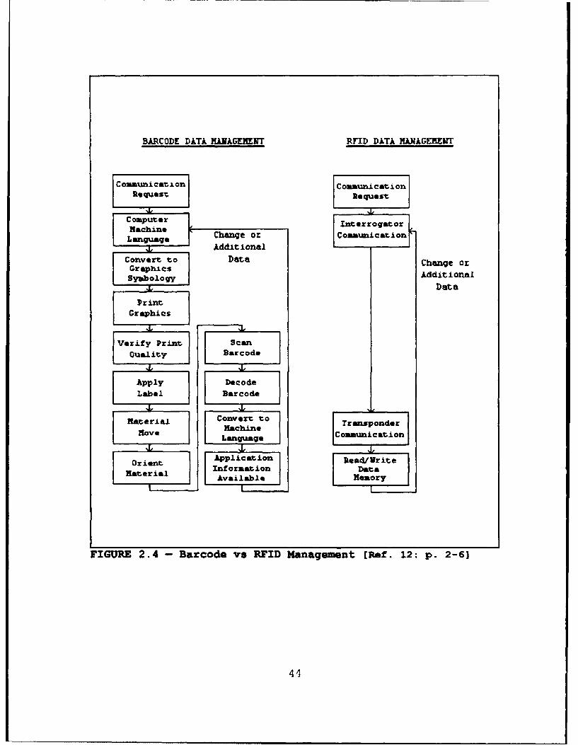
(2) Radio Frequency. Radio Frequency Identifi-
cation (RFID) refers to systems that read data from RF tags
that are present in an RF field projected from RF reading
equipment. Data may be contained in one or more bits for
providing identification and other information about the
object to which the tag is attached. [Ref. 4: p. 1-27]
RF technology employs a small integrated
circuit with an electronic memory, an antenna system, and a
reader. The reader functions similarly to the decoder in a
barcoding installation, and the antenna like a scanner;
however, this is where the similarity ends (see Figure 2.4).
A small RF transponder - or electronic identification tag -
stores data that is read by an antenna unit attached to a
reader. The identification tag can contain a fixed identifier
or it may be programmable, depending upon the type of system
in use. In passive RF schemes, tags have no internal power
source; on the other hand, in active RF, tags transmit stored
data back to the reader using their own power source (bat-
tery). The advantage of active devices is the greater
effective range over which tags can be interrogated/read.
[Ref. 11: p. 76]
Because RF noncontact systems use radio
frequencies to operate, MITLA devices operating on the RF
principle are susceptible to electrical interference (as in
42
any radio system). Similarly, RF systems can interfere with
other electronic devices. To reduce this risk of interfer-
ence, MITLA producers use low power and signal encoding
schemes. Tag reading, however, can be disrupted or degraded
by metal obstructions that prevent radio waves from reaching
the tags.
RFID systems and RF tags offer the following
general benefits that collectively, provide discernable
advantage over other MITLA devices (see Figure 2.4):
# Store/process large amounts of data.
* Provide read/write capability, allowing informationupdate regarding item status, content, and physicalcondition.
* Maintain read/write capability even when items they areattached to are moving and not in "direct" physicalcontact with interrogators.
* Operate over distances far greater than other systems(RFID reading range currently extends to approximately150 feet from interrogators).
*Allow placement under, in, or coverage by containers/products to which attached (physically inaccessibleareas) because they are not limited by "line of sight"restrictions. Furthermore, darkness, dirt, or other non-metallic opaque substances will not affect tag read-ability.
* Report directly to RF interrogators which then transmitdata to a CPU without human intervention.
43
BARCODE DATA MANAGEMNT RFID DATA MANAGEMENT
Comunication Communication
Re quest;e quest
Computer Interrogator
Language Change or Com-unication
' J, AdditionalConvert to Data Change orGraphicsSymbology Additional
1 Data
PrintGraphics
Verify Print ScanOuality J Barcode
Apply DecodeLabel Barcode
Material convert to Transponder1move Machin* ComimunicationJ
Orient ILngurageo D~
Orient Application Read/WriteMaterial Available Memory
FIGURE 2.4 - Barcode vs RFID Management [Ref. 12: p. 2-6]
44
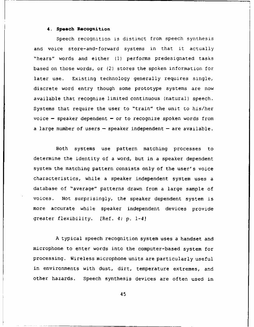
4. Speech Recognition
Speech recognition is distinct from speech synthesis
and voice store-and-forward systems in that it actually
"hears" words and either (1) performs predesignated tasks
based on those words, or (2) stores the spoken information for
later use. Existing technology generally requires single,
discrete word entry though some prototype systems are now
available that recognize limited continuous (natural) speech.
Systems that require the user to "train" the unit to his/her
voice - speaker dependent - or to recognize spoken words from
a large number of users - speaker independent - are available.
Both systems use pattern matching processes to
determine the identity of a word, but in a speaker dependent
system the matching pattern consists only of the user's voice
characteristics, while a speaker independent system uses a
database of "average" patterns drawn from a large sample of
voices. Not surprisingly, the speaker dependent system is
more accurate while speaker independent devices provide
greater flexibility. (Ref. 4: p. 1-4]
A typical speech recognition system uses a handset and
microphone to enter words into the computer-based system for
processing. Wireless microphone units are particularly useful
in environments with dust, dirt, temperature extremes, and
other hazards. Speech synthesis devices are often used in
45
conjunction with the speech recogý.ition unit to provide
feedback and direction to the user. These systems provide
automation capabilities in environments where users are not
computer literate or where keyboards or similar input devices
are not practical. Such systems could be designed to inter-
face with RF tags or other similar recording devices; however,
their contribution to maintenance management and CSS opera-
tions is constrained by today's "stand alone" speech recogni-
tion technology. [Ref. 4: p. 1-5]
5. Artificial Intelligence
Artificial Intelligence (AI) is the use of computers
to model the behavioral aspects of human reasoning and
learning. In problem solving, one must proceed from a
begiiii.ing (the initial state) to the end (the goal state) via
a limited number of steps. Research in AI is concentrated in
some half-dozen areas. Examples include game theory, pattern
recognition, natural language processing, and cybernetics.
In game theory the computer must choose among a number
of possible "next" moves to select the one that optimizes its
probability of winning; this type of choice is analogous to
that of a chess player selecting the next move in response to
an opponent's move. In pattern recognition, shapes, forms, or
configurations of data must be identified and isolated from a
larger group; the process here is similar to that used by a
46
doctor in classifying medical problems on the basis of
symptoms. Natural language processing is an analysis of
current or colloquial language usage without the sometimes
misleading effect of formal grammars. Cybernetics is the
analysis of the communication and control processes of
biological organisms and their relationship to mechanical and
electrical systems; this study has led to the development of
"thinking" robots. In this context, machine learning occurs
when a computer improves its performance of a task on the
basis of its programmed application of AI principles to its
past performance of that task.
The first essential difference between existing
computers and the human brain lies in the way their memories
are organized. In either case, the main problem lies in
retrieving information once it has been stored. The method
computers use is called addressing; it is possible to find a
certain piece of information if the address is known. The
human memory works in a very different way, using association
of data. The retrieval is done according to the content of
the information, not according to an external address artifi-
cially added to the useful content. That difference is
qualitative as well as quantitative. Man-made memory devices
are now constructed using associative principles, and there is
a great potential in this field with such new technologies as
holography and optical storage of data.
47
The second main difference between computers and the
human brain resides in the manner of dealing with the infor-
mation. A computer processes rigorously precise data. Man
accepts fuzzy data and carries out operations that are not
strictly rigorous. Also, computers perform only very simple
elementary operations, producing complex results by performing
a vast number of such simple operations at a very high speed.
In contrast, the human brain performs at low speed but in
parallel rather than in sequence, producing several simulta-
neous results that can be compared. In a computer, memory and
treatment are distinct; in man, they are mixed. [Ref. 13: p.
1034]
Related to AI, machine vision employs the same basic
idea as OCR in that it involves scanning an identifying object
and interpreting what it sees. Currently, machine vision is
used mostly in Computer Integrated Manufacturing (CIM) systems
to verify procedures or to measure assembly variations and
forward information to enable downstream operations to adjust.
Advances in AI and development of better pattern recognition
capabilities will make concepts such as machine vision more
practical options in sortation, inspection, and quality
control applications. [Ref. 14: p. A22]
The combination of new man-made components with
emerging ideas could result in entirely new AI technology in
48
the 21st century. Advancements in AI will certainly make the
challenge of command and control much easier to meet, however,
much of this technology is still in its infancy. At this
stage, AI concepts are high-risk, high-cost, and not within
DoD's "reach." The remarkable developments being made in AI
open the doors to many new military possibilities, nonethe-
less, DoD's actions must be balanced against a multiplicity of
current obstacles to ensure a viable force is in place to
capatilize on future AI developments. MITLA, in an open
systems concept, could provide the bridge to cross from
manual, repetitive actions to the mystical level called the
"state-of-the-art."
E. TECHNOLOGY CONSTRAINTS
Logistics support operations are influenced and con-
strained by each step in the logistics process. Constraints
range from procurement through operation, prepositioning,
embarkation/debarkation, and maintenance support operations.
The ability to successfully complete each step of the logis-
tics process directly impacts the commander's ability to track
the battle, anticipate requirements, locate equipment, manage
critical resources, and meet CSS requirements to help sustain
the force. AIT can be used at all echelons throughout the
Marine Corps, from the sustaining base or seabase, which could
be depots or installations, through the intermediate mainte-
49
nance activities, to the operational units on a 24-hour-per-
day basis.
This concept may be limited if the principal technology
and functional barriers to achieve an effective recording, and
tracking system based upon global and total asset visibility,
in-transit visibility, and improved maintenance management are
not addressed by DoD. The technology must be based on
gence, and interoperability (C41 2) in OMFTS scenarios. When
emplaced, this modernization and automation of logistics
operations will result in better support to operating forces.
Microchip tags (both contact/near contact and radio frequency)
are part of one such technology advancement. This thesis
explores the use of microcircuit technology for the storage of
preventive maintenance, equipment modification, and repair
data.
Many technologies have emerged over the last decade that
show promise for remedying the situation caused by the loss,
54
inaccessibility, destruction, and compartmentalization of
important logistics/maintenance data. The common thread among
these technologies is that they offer an alternative to
reliance on hard-copy documentation and manual record keeping.
Recent advances in data-recording technology offer the
opportunity to examine ways to improve existing systems that
are error-prone and require repetitive data entry. One of
these, barcoding, is an inexpensive method for identifying
items reliably and can be dependably employed when data about
items can be maintained satisfactorily in a central database.
Microcircuit technology is another advance that has come
to the forefront in recent years for relieving the burden of
manual record keeping. It offers the advantage of recording
and storing data reliably and eliminates the need to enter the
same data again. The advent of data communication terminals
and microchip tags that employ radio carrier waves for the
transmission of data is just beginning to be recognized as a
very promising technology. RF tags are becoming more capable
and usable in numerous data storage applications. As with
other recent advances in data handling, RF microchip technolo-
gy is now undergoing investigation as a means to improve many
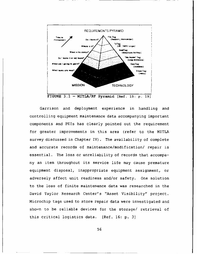
labor intensive logistics functions. in this regard, Figure
3.1 depicts one view of the correlation between requirements
and emerging RF technology.
55
REQUIREMENTS PYRAMID
Tim. m
PDo I have iV (bwor, tranamnitiOG
W3.!i-MITal/RF yr(daiba[e. 1lookup1
Do have it an my basse? W in ha nd(long disangce)
When am I s Go a so in amu e rqu
(%awale)
for gre~Wate ite ovm ent ass thsara(rfrtote&I
(ren&.y
MISSIONECHNOLOGY
FIGURE 3.1. - MITLA/RF Pyramid [Ref. 15: p. 19]
Garrison and deployment experience in handling and
controlling equipment maintenance data accompanying important
components and PEIs has clearly pointed out the requirement
for greater improvements in this area (refer to the MITLA
survey discussed in Chapter IV). The availability of complete
and accurate records of maintenance/modification/ repair is
essential. The loss or unreliability of records that accompa-
ny an item throughout its service life may cause premature
equipment disposal, inappropriate equipment assignment, or
adversely affect unit readiness and/or safety. One solution
to the loss of finite maintenance data was researched in the
David Taylor Research Center's "Asset Visibility" project.
Microchip tags used to store repair data were investigated and
shown to be reliable devices for the storage/ retrieval of
this critical logistics data. [Ref. 16: p. 3]
56
C. DESCRIPTION OF RFID TECHNOLOGY
RF technology involves the use of radio transmitters and
receivers to transmit and receive data in near real-time and
without connection, scanning, or human intervention. There
are two basic types of RF technology: passive (modulated
backscatter) and active (two-way transponder).
* Passive tags contain no internal power source. They areexternally powered and typically derive their power from thecarrier signal radiated from a scanner; however, externallygenerated power may prove unsuitable for use around somehazardous/explosive items. With backscatter technology, thetag is a "dumb" terminal that acts as a mirror to the radiowaves emitted by a scanner. When a tag is activated, theradio waves are reflected back to the scanner. When the tagis not activated, the waves are not reflected.
* Active tags use batteries as a partial or complete sourceof power, but have a limited useful life and must be replacedperiodically; tags can also include built-in diagnostics toinform the system when batteries are low. They are furtherdifferentiated by separating them into those with replaceablebatteries and those that have batteries inside a sealed unit.Currently the typical tag battery life is three years,depending on the amount of use, and rechargeable batterytechnology limits the size of the tag. (Ref. 17: p. 6]
4 Equipment costs are typically direct functions of RFIDmodtils, memory capacities, and reading ranges. The modelsused are broken into low and high operating frequency. Withlow frequency, tag values range from a low of $7 up to $210.Interrogator values are also quite varied, with a range from$500 to $4,500. The differences are largely in the packaging.With high frequency equipment, the greatest number of tags iin the $35 range with a high of $150. Scanner system costsrange from $1,200 to $5,600 because of the high cost of thereader points. The high frequency systems provide signifi-cantly different performance characteristics than low frequen-cy and that justifies the increased scanner costs. [Ref. 4:p. 2-6)
* The questions of tagging reliability and data integrityare often overlooked in the design of an AEI installation.The certainty that each memory module has been written to orread from correctly is the central issue. Data integrity isaffected by factors such as orientation, range, separation ofmodules, environment, and error management. Error checking isaccomplished in different ways by various manufacturers,however, the best AEI will not work if a tag is attached to anincorrect PEI. [Ref. 4: p. 3-28]
+ Any RF tagging system is subject to radio interference.High frequency signal energy is susceptible to absorption byliquids and grease, thus introducing signal attenuation anddistortion in environments such as maintenance facilities andshipboard spaces. Multi-pathing ("crosstalk") due to reflec-tion of emitted signals off surrounding metal is another pointto evaluate and is usually a limitation found in very highfrequency transmissions. (Ref. 4: p. 3-231
59
* RF tag manufacturers must press for industry-wide stan-dards if they are to achieve the widespread acceptance ofbarcodes or magnetic stripes. Currently, individual coun-tries' regulations assigning electromagnetic spectrum bandsare different from other countries and significantly impedeworldwide standardization. In fact, today these dissimilarpolicies encourage non-standardization. [Ref. 4: p. 6-9)
* Expansion must also be considered - all identificationtechniques and work stations required now and in the futureshould function together in a seamless C41 2/LOGAIS network.One disadvantage, or better stated, challenge, to working withAEI and portable database systems is that concepts of mainte-nance management must be revisited and new processes learned.This, however, will give the Marine Corps the opportunity toimprove its maintenance facility designs, maintenance produc-tion flow, and data process strategy.
D. FLEET OPERATIONAL NEED STATEMENT (FONS)
Emerging Marine Corps doctrine emphasizing high maneu-
verability and fire power with minimal lines of communication
requires timely logistics support of precisely what the
battlefield commander requires. This demands a logistics
system that maintains accurate, near real-time data on
commodity identification, "flight line" status, quantity, and
location, capable of quickly responding to demands from
forward combat elements. New technologies are required to
automatically locate and track logistic items, container
inventories, and equipment maintenance requirements; further,
technologies are also needed for data processing and informa-
tion management to record and transfer this data in support of
the logistics aspects of C11 2. To meet these goals the Marine
Corps has identified minimum desired characteristics, system
architec-ture, and support requirements as detailed in the
following subsections.
60
1. Desired Characteristics
The primary goal of the Marine Corps' Battlefield
Automated Identification Technology (BAIT) R&D initiative, of
which MITLA is a central component, is to provide near real-
time updates on supply inventory [Ref. 18: p. 4]. Although
not specifically addressed in the BAIT R&D initiative, the
MITLA technology chosen for inventory management should
provide a suitable platform to support key maintenance manage-
ment functions. Specific characteristics as delineated in the
FONS include:
* Tags and their supporting systems must be inexpensive,simple, and portable. Operation and application must becompletely intuitive with transparent operation, requiringlittle or no training. The goal is no additional labor, andpreferably a reduction in required work force. Manual dataentry should be only made once, and possibly not at all.
* Tags must be small, lightweight, and compatible withitems, including explosive ordnance and hazardous materials.They must be reliable, have long battery life, be very rugged,and operate in adverse military environments.
* Transmission must be secure, non-interceptible, and notsusceptible to either intentional or non-intentional interfer-ence. Tags must not generate a "signature effect" that can beused for adversarial targetting and homing.
* Transmission should operate over distances found in ware-housing yards and have Low Earth Orbit (LEO) satellitecommunications capability for greater distances.
* Tags and interrogators should talk to other tags andinterrogators within their area to form networks and relayinformation, or to read much less expensive tags attached toindividual items for automatic inventory of internal nesteditems. Operation must be unlicensed.'
5 The Federal Communications Commission (FCC) regulatescommercial radio communications, including licensed and unli-censed communications, in the United States. Licensedcommunications require the granting of a specific channel for
61
STags must have sensing capability including geolocation,time, temperature, humidity, weight, and break seal.
* Tags must have adequate data storage to support supply,embarkation, ammunition, and equipment technical data and tocontain complete container manifests. Tags must have internaldatabase capabilities to minimize tag communication intensityand to speed data searches.
* No new information systems/platforms must be required.Only the tags, interrogators, stands, cables, and portablecomputers that directly support the MITLA technology will beconsidered. New software must be supportable by current/planned DoD open systems architectures and communication/networking protocols.
* Secondary goals include:
"£ Locate items in storage.
"A Locate items issued and in use.
"• Provide near real-time update on supply.
"£ Provide In-Transit Visibility (ITV).
"£ Provide visibility of items during maintenance. [Ref.18: pp. 4-51
2. System Architecture Requirements
Additional system operating parameters include:
* International operability.
* Open/public domain protocols.
*Unique addressable identifier.
*Non-site license (international).
* Optional data security/data encryption.
* Data capacity adjustable to requirements.
a specific user, at a specific site, for a specific purpose.The advantage of licensed communications is increased range.The disadvantage of licensed communications is regulatorycontrol for each transmitter, user, and site. [Ref. 19: p. 1]
62
* Provide source data automation capability.
* Downward compatible (compatible with all transponderswith respect to interrogators).
* Unique transponder parameters to be considered are:
"A Read/writeable.
"& Automatic recognition.
"A Tag life span z ten years.
"A Various attachment methods.
" Battery durability a five years.
"A Non-orientation sensitivity (omnidirectional).
"A Data transfer rate of z 9600 baud and an upload/down-load time not to exceed one minute.
*Unique interrogator parameters to be considered are:
"A Discrimination.
"A Omni-directional.
"A Multiple transponder query.
"A Individual transponder query.
"A Memory buffer capacity z four Mb.
"A Variable attenuation (directional).
"A Transportation industry compatible.
"A Operable with 12/24 volts (fixed interrogator).
"A US military frequency bandwidth (225MHz-400MHz).
"A Solar operable/battery backup (hand-held remoteinterrogator).
A "Locate ability" (Global Positioning System [GPS] ordirectional finding capability).
A Personal Computer (PC) compatible Microsoft DiskOperating System (MS DOS)/DoD system integration. [Ref. 17:p. 7]
63
3. Support Requirements
Tags may be battery operated, requiring adequate
supplies of replacement batteries. Inexpensive tags must be
expendable, and new tags must be available to mark new items/
cartons. More costly tags must be reusable, but inexpensive
enough to be disposable after failure. Information management
will be hosted on either portable computers and/or existing or
planned C41 2 systems and equipment. Training should be offered
to individuals in C'I 2 and/or in the logistics community on how
to prepare and use tags and resulting software systems. [Ref.
18: p. 5]
E. USMC INITIATIVES
A USMC MITLA/RF system is under development to support
theater reception capability for CSS buildup ashore; enhance
MAGTF CSS effectiveness; and improve asset visibility, track-
ing, and documentation during retrograde operations. Capa-
bilities successfully demonstrated in the foregoing will form
the basis for applying MITLA/RF technology to MAGTF predeploy-
ment and deployment activities. Although primarily intended
to support a MAGTF commander's asset location identification
and tracking requirements, use of the USMC MITLA/RF system
prototype will support improved logistics functions in non-
MAGTF venues such as bases and stations.
64
The USMC MITLA/RF system prototype encompasses the
hardware, software, policy, and procedures required to apply
MITLA/RF technology, and, through interface with USMC LOGAIS
and non-USMC automated logistics systems, to integrate materi-
al movement and management data. LOGMARS technology will pro-
vide source data automation by permitting barcoded data to be
scanned and written directly into MITLA/RF hardware. This
linking of applied MITLA technology and integrated materials
movement and management data will give Marine Corps logisti-
cians improved asset location identification, tracking, and
control. [Ref. 12: pp. 1-2]
The primary objective of this process enhancement is to
significantly improve force preparedness in theater. The
MAGTF commander will immediately know equipment availability
and location. The result will be more effective and efficient
CSS, and increased combat readiness. The next logical
evolution in the system's development is an expansion to in-
clude equipment maintenance management.
1. SAVI R&D Effort
The Marine Corps is participating with the Navy for
MITLA/RF applications in a series of joint research and
development efforts. This is being accomplished as a Small
Business Innovative Research (SBIR) initiative that evaluates
available technology for MITLA applications. This effort
65
reviewed available inventory tracking RF technology for
selected prototype testing at five sites, three Navy and two
Marine Corps (Blount Island Command [BIC] and a North Atlantic
Treaty Organization [NATO] prepositioned site). The product
approved through the SBIR initiative was the SAVI tag.' The
technology and applications related to the tag are available
for exclusive Marine Corps employment. The prototype efforts
underway at USMC sites include:
* BIC Prototype. Conceptual design centers on implemen-tation of SAVI technology to support Maritime PrepositioningForce (MPF) operations at BIC. This prototype concentrates oncontainer management and major end item tracking during theMPF offload/maintenance cycle.
* NATO Prepositioning Prototype. An additional prototypeis underway for selected aspects of inventory management andinventory processing relative to prepositioning of NATOrequirements. This is anticipated to be a static environmentcapitalizing on SAVI applications concerning shelf life andinventory security. [Ref. 21: p. 4]
2. Description of SAVI Tag Technology
The SAVI Technology TyTag is an RF asset management
device that uses a radio transmitter, a receiver, a micro-
computer (console), and memory to automatically track the
location of an object to which attached. The TyTag system can
I As announced in the Commerce Business Daily, SaviTechnogoly, Inc., was awarded a sole source contract forprocurement of radio frequency transponders, fixed interroga-tors, and hand-held interrogators (including maintenance).The equipment must be capable of operating on ships, air-planes, and land vehicles and in artic, desert, and tropicalclimates, including areas with high levels of electromagneticinterference. [Ref. 20: p. 32J
66
track the position and movement of containers, vehicles, major
end items, and inventory from a remote position, regardless of
the number of tags in the area. Using a microminiature radio
transmitter it can locate an item in a warehouse, marshalling
yard, container port, or aboard ship. Another variant uses a
unique radio communication system to periodically monitor the
movement of tagged items within a facility. As tagged items
pass check points, a microprocessor begins an encoded exchange
with the TyTag (via RF) and the system then accurately identi-
fies tagged items and their locations, all without human
involvement. (Ref. 21: Encl. 1: p. 1]
TyTag systems consist of four components: the TyTag,
an interrogator, a console, and a sniffer (see Appendices E
and F). The TyTag is affixed to an asset to be tracked and
contains a small transmitter/receiver. Interrogators can be
either permanently installed or used as portable antenna sets
that can be mounted on ceilings, or on masts/tripods (e.g.,
telephone pole) in marshalling areas. The purpose of an
interrogator is to communicate/transfer data between individu-
al tags (via RF) and consoles. The console is a microcomputer
that manages the communications with the interrogator and
serves as a point of entry into the inventory tracking/
management system. It has a graphical interface for easy
access to the database dependent upon the type and application
of the SAVI tags employed. Properly configured, this micro-
67
computer software could support MAGTF LOGAIS for container
manifesting, inventory management of container contents, and
general receipts, issue, and storage functions. The last
component, the sniffer, is a hand-held portable interrogator
used to locate assets and read/write data to TyTags. [Ref.
21: Encl. 1: p. 11
The following sections discuss the primary features of
the TyTag and the family of SAVI TyTag-based products [Ref.
21: Encl. 1: pp. 2-3):
* Unlicensed Use. SAVI's products do not require a sitelicense for use. They operate at a frequency within the FCC'sunlicensed communication band.
* Read Range. Tags have a read range from fixed interro-gators of 30 to approximately 150 feet. The exact range willdepend on the system development requirements.
* Data Capacity. Various tag models have memory caoacitiesranging from 1024 bits (120 characters) to 64,000 bits (18,000characters) with models under consideration with even greatercapacity.
4 International Use. SAVI's tags can be developed forinternational use. The operational concept enables tags tooperate unlicensed worldwide. Fixed and portable inter-rogators can be set to operate on a specific country'sunlicensed frequency band and tag receiver's can then scanthrough unlicensed ranges until the appropriate range isfound.
* Active Tag/Transmitting. Tags are based on two-waytransponder communication. This permits direct, low powercommunication between the tag and the interrogation units.SAVI's system software provides the capability to readmultiple tags within a single area and have them be reliablyidentified. Line-of-sight to the interrogator is not re-quired.
* Location Finding Capability. By outfitting an area withinterrogators, wide area inventories can be taken. Interroga-tors are instructed to read tags and then data from all
68
interrogators can be fed into a host computer where data canbe stored, processed, and/or analyzed. The system softwarecan determine the proximity of a tag between several interro-gators permitting its location to be identified in respect tothe interrogator receiving the strongest signal.
* Interrogators. Tag systems can be operated with eitherfixed or portable omni-directional interrogators.
A Fixed interrogators are typically placed at entry/exitpoints to facilities to identify movement in or out. Addi-tional fixed interrogators can be mounted throughout facili-ties to provide complete coverage of an area for wide areainventory and asset management functions. In enclosedfacilities, a single antenna will cover an area of 10,000square feet. For open storage, a single antenna will supportan area of 2.5 acres.
A Portable interrogators have been developed to work inplace of a series of fixed interrogators. They provide thecapability to move through facilities and read tags as theycome within reading range. Read range for portable interroga-tors is less than that of fixed versions.
F. VIABLE MITLA/RF APPLICATIONS
The infusion of RF technology shows unlimited potential
for the Marine Corps in many functional areas. The family of
RF/AEI tags can be modified and integrated into existing
LOGAIS systems to provide the following support capabilities:
The basic version of the RF tag supports container
tracking, container manifesting, and inventory management. A
tag is attached to an item, such as a container or vehicle, to
identify an asset and its location. A modified version of the
tag can be used to support container manifesting. Essential-
ly, as containers are loaded with materials, the contents can
69
be recorded on a PC and upgraded to support RF/?EI using a
LOGMARS-type application. The Marine Corps' standard PC, used
to support MAGTF LOGAIS, could be configured and employed to
upload/download inventory records to tags. This procedure,
which can be accomplished on demand, can update tags to
reflect current asset inventory. Conversely, as inventory is
withdrawn, tags can be debited to support inventory manage-
ment.
The security tag, a modified version of the basic com-
mercially available system, has been developed to provide a
capability to monitor container security. This tag is an up-
graded tag outfitted with a fiber optic loop that passes
through the locking mechanism of the container. When the lock
is opened the fiber breaks and the tag records the date and
time of the security violation. When the container passes in
or out of a check point, an interrogator checks the tag's
status, reads it as violated, and sounds an alarm. Addi-
tionally, these tags can communicate with interrogators to
sound an alarm if the container is broken into. With proper
placement of either permanent or portable antennas, security
personnel can monitor a marshalling yard or staging area from
a central station.
Another modified version of the commercially available
tag can provide environmental support management to enable a
70
system to read and monitor ambient conditions within con-
tainers, storage areas, or other facilities. For e::ample, on
refrigerated containers, a sensor tag can be mounted to the
refrigeration unit to measure temperature changes and gener-
ator fuel/oil levels. Should performance be outside estab-
lished ranges, the incident can be recorded and an alarm
sounded, as with the security tag.
Finally, the basic tag is ideally suited to store
maintenance records of major end items or subassemblies as
they move through maintenance processes or in storage awaiting
issue. With the capacity to both read and write to tags,
"'maintenance records" can be updated to reflect equipment
status changes. For items requiring scheduled PM, modifica-
tion, and calibration, all pertinent data can be stored on the
tag. For items inducted into depot maintenance activities,
tags provide a method to track locations and statuses of
subassemblies as they move through the maintenance cycle
[Ref. 21: Encl. 1: pp. 3-4]. Chapter IV will further develop
potential maintenance applications and integration strategies
for MITLA RFID technology.
71
IV. INTEGRATION STRATEGIES
A. GENERAL
The most critical factor in OMFTS and maneuver warfare is
to "get the right thing, in the right place, at the right
time." Supporting this requires equipment be identified,
tracked, and maintained along logistics lines to sustain force
readiness. Traditionally, the CSS maintenance community has
accomplished this by attaching a manual paper Equipment Repair
Order (ERO) to PEIs and/or central components. From there it
is hoped that EROs remain with equipment throughout mainte-
nance and storage - usually they do.
During the mid-1980s, the CSS supply community was
introduced to advanced technology; barcodes could now provide
equipment with a "license plate," an identification tag that
a computer can read for a machine or operator. Awkward and
difficult routine work tasks were left to machines, and
operators were given more advanced, skilled tasks. Supply
efficiency, accountability, and readiness increased. Barcodes
do, however, have limitations. They can only accommodate a
small quantity of information; data cannot be changed,
dependency on a master computer increases, and they are
sensitive to dirt and heavy handling.
72
RFID and portable database systems provide a new alterna-
tive to CSS information challenges. Small, durable, fle.:ible
data modules with sizeable memory capacity provide efficient
mini-read/write data files for each PEI. By lifting files
from supporting CPUs and information from manual forms/
records, logisticians now have the capability for each PEI to
be intelligent and carry its own data while being stored,
moved, and maintained. Communications between devices and
LOGAIS applications, such as maintenance/supply management
systems, now become easier because they are reading and
writing common data in a common format.
B. EXISTING TECHNOLOGY AND PROCESS FLOW
The MAGTF Deployment Support System (MDSS) is used for
unit level tracking. This system is an AIS designed with the
capability to provide a commander with near real-time visibil-
ity of PEIs and major systems throughout an MPF operation.
The system uses scanners that scan and record information con-
tained on barcodes attached to equipment. Scanned data
elements usually include the time, location, and equipment
identity (note the absence of any maintenance information).
However, exercises have shown that although this system is
conceptually sound, it has not been effective as a tool for
gauging either off-load status or throughput status during an
operation. [Ref. 17: p. 25]
73
Factors identified as contributing to the ineffectiveness
of the LOGMARS/MDSS-II system include:
4 Incompatible system databases used throughout MPFoperations.
* Extensive training and cohesiveness required for supportpersonnel.
* Labor intensive reentry of unit-level information toaccommodate interface with non-USMC LOGAIS systems.
* Improper system implementation such as disjointed arrivalof LOGMARS equipment, poor scanning point positions, and lackof information about whether scans were successful.
* Equipment operation failure due to bright sunlight, dirt,and grease buildup on barcodes/scarners.
As elaborated in Chapter II, MIMMS-AIS is used to track
Marine Corps maintenance work-in-process, and, with MARES,
provides commanders and logisticians with maintenance/
readiness visioility. However, as also addressed earlier,
these systems do not support equipment modification management
and PM scheduling/status reporting. Additionally, the current
system only marginally sustains a commander's maintenance
management requirements for areas other than modification/PM.
This dissatisfaction is clearly highlighted in the results of
a "questionnaire-type" survey conducted by the authors.
The MITLA/RF survey, as shown in Appendix G, consisted of
a cover page and a series of questions designed to elicit a
respondent's (1) satisfaction with current maintenance
management systems, (2) position regarding MITLA/RF's applica-
tion to modification/PM, and (3) recommendations regarding
74
other (if any) technologies requiring investigation. The
survey was distributed at the Marine Corps' 1993 Biennial
Maintenance Management Conference and was preceded by a
detailed MITLA concept briefing given by HQMC I&L representa-
tives. Conference attendees represented all major USMC
logistic activities, bases, and fleet commands, and consisted
primarily of logistics and maintenance officers. Each of the
twenty-three attendees was given a survey after the HQMC
briefing and the results are summarized as follows:
+ Concerning satisfaction with tracking/recording mainte-nance in garrison, on a scale of one through ten where onerepresented "Not Satisfied" and ten "Extremely Satisfied," theaverage response was 3.2 (see Figure 4.1).
+ Relative to satisfaction with tracking/recording mainte-nance when deployed, on a scale of one through ten where onerepresented "Not Satisfied" and ten "Extremely Satisfied," theaverage response was 2.7 (see Figure 4.1).
* 77% of respondents suggested that modification controland PM scheduling should be the "point of entry" for introduc-ing MITLA/RF into the maintenance community; however, a commonthread was a concern that any improvement in maintenancemanagement operations address LOGAIS compatibility, flexibili-ty, and near real-time data throughput when deployed.
* When asked to rank several fundamental issues regardingMITLA/RF implementation, respondents indicated that workloadreduction and system reliability should receive the principalfocus (see Figure 4.2).
* Alternatives for MITLA/RF application to maintenanceoperations encompassed a host of recommendations to enhancecurrent procedures. Suggestions included using MITLA/RF foreliminating all maintenance forms/records, tracking work-in-process (WIP), dispatching equipment, controlling repairparts, storing and accessing technical manuals, and simplify-ing operations through augmentation with other technologies(smart cards, barcoding, CD-ROM, etc.).
75
80 Dep2.oyed
0 Garrisor.
6
R
e
p0 4n
e 3
2
0
FIGURE 4. SaifcinWt antnneMm ytm
ComptibiityCostCo~tb15% 10%
Reliability2 1
Comp~lexity19%
14% Reduction21%
FIGURE 4.2 -MITLA/RF Priorities
76
C. OPERATIONAL CONCEPT
The envisioned operational concept is to attach tran-
sponders or tags to PEIs enabling them to remotely "hear",
"respond", and "talk" with C'I2 systems. Logistics information
will be attached to PEIs and automatically reported to C4 1'
systems with minimal human intervention. PEIs will be able to
report what they are, who they belong to, wnere they are, and
what their status is. The result will be "talking" and
"intelligent" PEIs.
Information, incorporated into tags, will follow items
and provide "escort" databases, thus eliminating lost informa-
tion caused by limited access and disconnects to LOGAIS and
destroyed equipment records. Since transponders will be fully
integrated into C4 I2 and supported by LOGAIS, they become a
vital, near real-time link to pass information to commanders
and other systems.
Tag information will be dispersed using modern distribut-
ed information management technologies into a family of
planning and logistics systems that integrate funcitional
areas of planning, supply, transportation, embarkation, and
maintenance. Such a system will go on to aggregate data from
the small unit level up to joint commands. These technologies
and systems will be used to provide rapid, robust, and
dynamically reconfigurable LOGAIS systems that will rapidly
77
process and distribute information. The net result is that
command and control will be extended down into the logistics
systems and to the PEIs themselves. The resulting capability
will provide commanders and logisticians information on the
location and status of every item, whether in storage, in
transit, in maintenance, or on the battlefield.
The functional management responsibility for MITLA/RF, as
it pertains to capturing maintenance data, PEI accountabilty,
and equipment status, should fall upon logisticians. However,
logistics information functions, as integrated into C'I 2 ,
should fall under the cognizance of the communica-
tions/electronics community (mirroring how logistics manage-
ment and systems/database management responsibilities are now
assigned). Accordingly, RF tags and data subsequently
transmitted to logistics activities should be managed by the
communications/electronics community. This concept should
contribute to complete data compatibility and integration of
logistics into tactical information systems, provide the
capability for secure communications, and permit storage of
aggregate classified logistics information. [Ref. 18: p. 3]
D. MITLA/RF SYSTEM DATABASE
During the Marine Corps' MITLA/RF container visibility
evaluation, the prototype database was initialized with the
following asset data: (1) equipment category, (2) asset type,
78
(3) equipment owner, and (4) assest ID. When the above data
was entered into the database, RF tag IDs were assigned to
PEIs. Asset data did not reside in the RF tags; it resided in
the system database on the central computer.' However, this
structure was a function of memory capacity. As tag capaci-
ties increase, asset data can be selectively downloaded to
ease equipment transfer beyond the reach of supporting central
computers. [Ref. 22: p. 10]
The methods used in structuring data on MITLA/RF tags can
greatly affect the performance of supporting LOGAIS systems.
As data storage requirements become greater, and more informa-
tion is carried with PEIs, data required for logistic func-
tions could become noncontiguous and the need for multiple
access to tags may become necessary - thus slowing system
throughput. It is important that the most frequently read
data be put in consecutive order to prevent excessive cycle
times resulting from too many reads or writes within one
cycle. Therc is almost an infinite number of uses for tag
memory, and with memory capacities increasing as envisioned,
the only restriction to data size is the cycle time of the
supporting system. [Ref. 4: pp. 4.39 - 4.41]
7 The SAVI TyTag which was used during the evaluation had
a 128 character memory capacity.
79
Concerning modifications and PMs, an MITLA/RF central
database should provide information to accurately identify:
(1) the basic supply elements listed above, (2) required and
completed modifications, and (3) required PM services. Data
should simply provide modification status and streamline the
generation of PM schedules (i.e., quarterly, semiannual,
annual, biennial, triennial, etc.). As described above,
MITLA/RF data should be available for tag downloading whenever
equipment is transferred to MAGTF units, retrograded/evacuated
to maintenance activities, or loaned to other units for short-
term use; it should not be necessary to maintain this informa-
tion on RF tags indefinitely. Thus, any unit supported by
MITLA/RF can quickly and accurately evaluate modification/PM
status without a herculean effort to locate, reconcile, or
generate required forms/records.
Once "obsolete" forms, such as modification control and
preventive maintenance records, are streamlined by the
logistics community to identify only the most critical
elements, information can be easily translated into a PC-type
database requiring only routine data entry skills. To
minimize the learning curve for data entry clerks, data
parameters would simply mimic current form entries and avoid
new terms/concepts. It can also be anticipated that the same
data entry clerks now entering "maintenance-in-process"
information will also b: tasked to input modification/PM data
80
which will minimize overhead, training, and "growing pains."
These automation efforts could be integrated into forthcoming
systems such as the Asset Tracking Logistics and Supply System
(ATLASS) negating the requirement for additional supporting
system/hardware platforms.
E. SYSTEM INTERFACES
MITLA/RF hardware makes near real-time, actual status and
tracking of assets possible. However, what truly adds value
to the MAGTF's CSS functions is this system's ability to
interface with other LOGAIS, integrate maintenance management
data derived therefrom, and link it with hardware provided
data, then subsequently generating user-defined reports for
decision making. Ideally, MITLA/RF systems should not
supplant current tools for logistics management. Rather, its
purpose should be to enhance their performance through
integration and communication among CSS information systems.
Current systems such as MDSS II and the Landing Force
Asset Distribution System (LFADS) provide MAGTF commanders the
capability to manage and distribute supplies/equipment from
data assumed to be accurate. However, these systems do not
show MAGTF commanders the near real-time physical status and
location of PEIs that may be required immediately. This
capability is a primary feature of RF tag technology. Data
collected through MITLA/RF will be passed to and processed by
81
appropriate LOGAIS component systems more quickly than can be
achieved by handwritten records or LOGMARS-type scanning
devices. This will provide MAGTF commanders and subordinate
element commanders more current and accurate decision making
information.
LOGAIS represents a logical resource to integrate data,
test interfaces, and confirm design requirements for RF
applications necessary to support MAGTF commanders. MITLA/RF
will enable LOGAIS users to rapidly access maintenance
management data through interfaces and interaction with
systems such as: ATLASS, MDSS II, LFADS, Transportation
Coordinators' Automated Information for Movements System (TC
AIMS), LOGMARS, and the MAGTF Data Library (MDL).'
A synthesis of MITLA/RF with the future ATLASS system, a
system designed to develop a new way to conduct ground
maintenance and supply at unit and intermediate levels, may be
the ideal solution. This synthesis is particularly inviting
because ATLASS will not only replace MIMMS, MARES, Supported
Activities Supply System (SASSY), Medical Logistics System
' MDL consists of a database comprised of standardizedmanpower and materiel-related files from which source datasets are created for use in the LOGAIS family of systems. Fordetailed specifications on the Marine Corps' prototype designsconcerning operating/communication systems, Structured QueryLanguages (SQL), and Relational Database Management System(RDMS) parameters, refer to the USMC Prototype InitiationReport [Ref. 12: p. 2-3].
82
(MEDLOGS), and the Ammunition Logistics System (AMMOLOGS), but
will also enhance current interfaces with the LOGAIS family of
systems [Ref. 23: pp. 11-12]. Further, this symbiotic rela-
tionship has the potential to greatly advance the integration
of various maintenance management functions, both horizontally
and vertically.
F. A MAINTENANCE MANAGEMENT "GAME PLAN"
RF technology can be used in maintenance management
operations to perform a variety of administrative, historical
record keeping, and asset tracking functions. It is helpful
to think about tags being partitioned into distinct segments
as is common on hard disk drives on PCs. These segments can
then be used for various purposes. One segment could be used
to contain basic "data plate" type information. This would
allow reading vehicle specific data (such as serial number,
nomenclature, etc.) but not changing it. This would ensure
that data would not accidentally be changed or erased. In
effect, this portion of a tag would provide constant, consis-
tent source data automation specific to PEIs. It would also
serve to simplify source data automation for other applica-
tions. [Ref. 24: p. 22]
An organization owning a vehicle could use the read/write
portion of a tag to enter unit specific data as well as any
record book/hand receipt information that may be required.
83
Tags could also store unit and organizational maintenance
information. This would allow units to perform such opera-
tions as "polling" their motor pool to determine which
The primary focus for any deployment of Marine Corps
forces is the performance of a specific mission, and all
activities associated with deployment must be assessed in
terms of how effectively they support the successful execution
of that mission. Within the Marine Corps the key component
for execution of the mission is the tactical maneuver element.
Therefore, the logistics train, should, theoretically, be
tailored to optimize support of the maneuver element.
Effective logistics support means (1) getting what is
needed, when it is needed, and where it is needed, and (2)
maintaining sufficient flexibility to minimize operational
constraints due to limitations in logistics support. Obvious-
ly there are limitations on resources, personnel, and trans-
portation assets that preclude meeting every conceivable
contingency. There are, however, ways to restate these goals
in reasonable and realistic terms that apply directly to the
logistics and maintenance process:
* Streamline and redefine maintenance management doctrinein support of dynamic force structures and OMFTS concepts.
* Reevaluate current maintenance record require-ments/information, determine specific reporting/trackingneeds, and automate the collection/maintenance of the informa-tion.
* Collect, transmit, process, and integrate maintenancemanagement data with all supporting LOGAIS systems, throughAIS/AIT (such as MITLA/RF).
* Provide decision makers, at every organizational level,access to "live" maintenance management information.
91
* Enable the force to sustain its CSS mission objectives ina reduced work force environment.
Additionally, with the achievement of these objectives
and MITLA/RF implementation, maintenance operations could
capitalize on the following opportunities. For instance,
applying MTTLA/RF to PM would provide a significantly better
monitoring system leading to a reduction in CM requirements.
In this scenario, demands for spares decreases, inventory
systems respond more quickly, maintenance forecasting models
improve, mechanics focus on "wrench-turning" vice paperwork,
and PEI operational availability increases. Furthermore,
replacing/improving other maintenance records with MITLA/RF
could reduce diagnostic and repair time (quicker turn-around-
time). In summary, implementation of MITLA/RF would con-
tribute to more responsive inventories, better use of supply/
maintenance personnel, and higher operational readiness at
lower maintenance costs.
However, before these goals and the MITLA/RF concepts
discussed herein can materialize, several significant limita-
tions must be addressed: (1) accessibility to "real world"
test/maintenance data, (2) availability of baselines for
aggregate labor hours/costs expended during maintenance
management functions, and (3) measurability of MITLA/RF'S
"%added value" to support maintenance and OMFTS operations. In
the -ame vein, follow-on efforts are also required toward
92
conducting cost/benefit analyses of MITLA/RF (as applied to a
MAGTF or major subordinate command); programming the acquisi-
tion, life-cycle, and provisioning elements of the technology;
generating RF tag database structures; and designing requisite
LOGAIS interface modules.
As Lieutenant Colonel Johnson deftly states in his
article, State of the Art: Not So Fast, the Marine Corps must
ensure that the basic warfighting skills already mastered and
proven without the aid of state-of-the-art technology remain
intact and on standby. Advancements in technology have made
the challenge of command and control much easier to meet, yet
considerably more complex. Combat leaders today are faced
with an overwhelming amount of data that must be stored,
analyzed, and used to make complete, sound tactical decisions.
High-tech developments in data processing have yielded
incredible increases in the quantity and speed of data
available to commanders. The difference between combat
triumph and disaster is, of course, the quality of that
information. The key issue in any future AIS/AIT development,
to justify the effort, must be improvement in the quality of
information available. It is essential that the Marine Corps
continue to move forward in R&D; however, there must be a
balance between the degree of sophistication that should be
employed and what could be deployed - a balance in how far and
fast the Corps moves in technology. [Ref. 25: p. 4 4 ]
93
C. FINAL REMARKS
New concepts of operation and associated doctrine for
employment of Marine Corps expeditionary forces are being
developed to address future threat scenarios. These concepts
of Over-the-Horizon (OTH) amphibious operations, and maneuver
warfare (MW) represent a significant change in amphibious
warfare. The OTH amphibious operation is a seaward extension
of the Marine Corps' philosophy of MW; significant changes are
required in the concepts of operations and equipment for CSS
to sustain forward deployed maneuver elements. The Advanced
Amphibious Logistics Technology (AALT) project, as chartered
by the Marine Corps Research, Development, and Acquisition
Command (MCRDAC), is designed to develop a plan for R&D
between now and the year 2010 to provide operational systems
and techniques for responsive CSS in an OMFTS environment. A
key aim of the AALT project, with direct bearing on the scope
of this thesis, is the plan to prioritize and schedule R&D for
systems that will: [Ref. 26: p. 1]
* Simplify procedures and reduce costs associated with CSSfunctions.
*Enhance combat support capabilities with existing orreduced workforce levels and skill level requirements.
* Provide for interface of LOGAIS systems with interrelatedareas, such as communications, intelligence, etc.
* Identify and develop technologies to expedite locatingand transferring materials on an on-call or as required basisin support of deployed forces.
* Move large volumes of material, supplies, and equipmentto combat units across shorelines and into forward areasfaster than with existing capabilities.
94
Both OTH and MW operations preclude developing substan-
tial CSS maintenance capabilities on shore. This suggests
that echelons III and IV maintenance must be provided by (1)
CSS personnel aboard a sea-based maintenance facility, (2) CSS
personnel who are transported, along with necessary equipment,
to the combat zone, or (3) unit maintenance personnel trained
and equipped to provide a higher level of maintenance them-
selves. The "fixed forward" concept will require higher
levels of maintenance be performed in the field, and increase
transportation requirements for delivery of spare parts and
perhaps CSS personnel. This increased transportation of
replacement parts, including subassemblies, will further
stress supply, transportation, and communications channels.
This will only be heightened when supply is provided from a
sea-based supply platform located OTH. (Ref. 26: p. 22]
A corollary to the "fixed forward" concept is the forward
push of class IX (replacement parts) to maneuver units. This
will help reduce time lags due to the requisition cycle,
especially for replacing maintenance-related spares such as
filters and batteries. "Consumption rates" of spare and other
replacement parts must be accurately estimated from historical
maintenance data, and be prepackaged, ready for supply to
maneuvering elements. This directly feeds into the require-
ment for a knowledge-based supply/maintenance AIS, and a
paperless maintenance WIP/spare requisitioning system to
95
relieve maintenance personnel of administrative burdens and to
elicit the responsiveness called for under the OTH/MW concept.
[Ref. 26: p. 22]
Most Marine Corps CSS operations require using paper-
based administration and tracking systems. The increased pace
and flexibility integral to MW operations cannot be met by the
current CSS paper and computer-based information systems. A
new AIS for maintenance support needs to be developed with
capabilities for (1) near real-time WIP visibility, (2) repair
part requisition, shipment, logging, and tracking, (3)
calculating updated projections of maintenance requirements
(RCM-based), and (4) identifying equipment configurations and
readiness postures. Without the ability to physically anchor
maintenance assets at established Beach Support Areas (BSA),
sea-based efforts must rely on the accuracy and "live"
transmission of recorded maintenance/supply information.
[Ref. 26: p. 24]
An automated means for determining exact maintenance
requirements and status must be developed. Ideally, the
method chosen should be directly interfaced with the support-
ing supply AIS. AIT should be exploited to develop this
capability. To operate effectively, the system must remain
simple to use and not produce additional "bookkeeping" tasks
for maintenance personnel. Emerging technology, such as
96
MITLA/RF, now being considered by the Marine Corps' supply
community for inventory management could make automating
maintenance management procedures feasible and provide a
FMECA Failure Modes, Effects, and Criticality Analysis
FMF Fleet Marine Force
FMFPAC Fleet Marine Force Pacific
FONS Fleet Operational Need Statement
HQMC Headquarters Marine Corps
GPS Global Positioning System
I&L Installations and Logistics
ICR Image Character Recognition
ISMO Information Systems Management Office
ITV In-Transit Visibility
LAN Local Area Network
LEO Low Earth Orbit
LFADS Landing Force Asset Distribution System
LMCC Logistics Movement Control Center
LOGAIS Logistics Automated Information Systems
LOGMARS Logistics Applications of Automated Marking andReading Symbols
LORAN Long-Range Navigation
LTI Limited Technical Inspection
MAGTF Marine Air-Ground Task Force
99
Mb Megabyte
MARES Marine Corps Automated Readiness Evaluation System
MCLB Marine Corps Logistics Base
MCRDAC Marine Corps Research, Development, andAcquisition Command
MDL MAGTF Data Library
MDSS MAGTF Deployment Support System
MEDLOGS Medical Logistics System
MEF Marine Expeditionary Force
MHz Megahertz
MI Modification Instruction
MIMMS Marine Corps Integrated Maintenance ManagementSystem
MITLA/RF Microcircuit Technology in Logistics Applications/Radio Frequency
MCO Marine Corps Order
MPF Maritime Prepositioning Force
ms millisecond
MS DOS Microsoft Disk Operating System
MTBF Mean Time Between Failure
MW Maneuver Warfare
NATO North Atlantic Treaty Organization
NAVMC Navy/Marine Corps
NCEL Naval Civil Engineering Laboratory
OCR Optical Character Recognition
OMFTS Operational Maneuver From The Sea
OTH Over-the-Horizon
PC Personal Computer
100
PEI Principal End Item
PIN Personal Identification Number
PM Preventive Maintenance
RCM Reliability Centered Maintenance
R&D Research and Development
RDMS Relational Database Management System
RF Radio Frequency
RFID Radio Frequency Identification
ROM Read-Only Memory
RPV Remot-l.y Piloted Vehicle
RTT Recording and Tracking Technology
SASSY Supported Activities Supply System
SBIR Small Business Innovative Research
SQL Structured Query Language
SRAM Static Random Access Memory
TC AIMS Transportation Coordinators' Automated Informationfor Movement System
I'M Technical Manual
TPFDD Time Phased Force Deployment Data
WAN Wide Area Network
WIP Work-in-Process
WORM Write Once, Read Many
WS/EM Weapon System/Equipment Manager (Alert)
101
APPENDIX B (List of Key Terms)
Artificial Intelligence/Expert System (Al/ES). The science ofmaking machines do things that would require human intelli-gence. An expert system is an intelligent computer programthat uses knowledge and inference procedures to solve diffi-cult problems that would typically require significant humanexpertise for solution. Knowledge necessary to perform atthis level, together with the inference procedures used, modelthe "best" practitioners in the related field.
Automatic Equipment Identification (AEI). A system that usesRF transmissions to collect and transfer specific equipmentidentification data. An AEI system consists of AEI tags (oneper item) and AEI reading devices. As an item is broughtwithin range of a reader, the reader interrogates the tag andcan read/write information as required. This information canthen be relayed to the system's host computer for storage andprocessing.
Barcode Template. A list/menu of specially prepared barcodesrepresenting specific data to be read by a scanning device andinterpreted on a display terminal.
Byte. Number of bits (binary digits) representing a characterfor use in software or hardware manipulation. There istypically eight bits to a byte.
Contact Tag. A microchip tag which requires physical contactwith a reading device for the transfer of data.
Data Collision. Interference caused by the attempt of an RFantenna to receive radio signals simultaneously from more thanone source. Requires programming of software protocols toregulate reception and processing of radio signals.
Data Integrity. The degree of accuracy to which data trans-mitted by RF signal is received and interpreted by a reader.
Echelons of Maintenance. There are currently five maintenanceechelons within the USMC maintenance support function. Thefirst echelon is maintenance performed by the equipmentoperator. This is normally preventive in nature. Secondechelon maintenance is performed by trained mechanics locatedwithin the organization. This echelon is responsible forextensive PM and limited component/part replacement. Thirdechelon maintenance is performed by specially trained person-
102
nel, cometimes found within an organization, but often locatedat a centralized maintenance site. Third echelon mechanicsare responsible for repairing subassemblies, componentexchange, and calibration. Fourth echelon maintenance isperformed by CSS elements. This level is involved with end-item overhaul and component repair. Fifth echelon maintenanceperforms major rebuilds in industrial type facilities.
Electronic Data Interchange. A standard technique used toexchange business information via electronic means. Theinformation may be a financial business transaction, aninventory replenishment order, order entry, an invoice, apayment, drawings, E-mail, etc.
First Read. The occurrence of receiving and accuratelyinterpreting an RF signal on the first attempt. First readconsistency is the maximum distance between tag and readerthat a signal is received and accurately read on the firstattempt.
Flash Memory. Electronic memory that provides high-speed,nonvolatile storage of programs or data. Whatever is recordedonto flash memory stays in the memory chip, even if the poweris turned off. To record over a previously used area, ahigher voltage is directed to the memory address, clearing thedata. This area can then be used again for storage.
Interrogator. A tripod/ceiling mounted radio transmitter andreceiver that relays data between RF tags and a system's hostcomputer.
Laser Card. A technique of optically encoding/decodinginformation on a heat sensitive stripe via laser. Thismoderately expensive optical technology allows text, graphics,or digitalized sound to be stored and retrieved from a creditcard sized housing media. Very closely related to Write-Once-Read-Many (WORM) technology.
Logistics Applications of Automated Marking and ReadingSymbols (LOGMARS). Technology that employs machine-readablesymbology (such as barcodes) and a scanning device that isable to read this encoded information. This information isthen relayed to a database for further analysis.
Magnetic Stripe. A generic term applied to an inexpensivestructured information storage/retrieval methodology. Thismethodology is characterized by a magnetic stripe attached toa credit card housing and the capability to store a low volumeof information.
MAGTF Deployment Support System (MAGTF/DSS). An automatedunit-level deployment planning and execution system that
103
provides MAGTF's and their subordinate elements the ability todevelop plan specific force structures (personnel, supplies,and equipment) . At execution, the system provides near real-time retrieval of information in the form of reports, list-ings, or data sets for export to other systems.
MAGTF II. A microcomputer based system that modernizes theMarine Corps' war planning capability. This system willsupport crisis and deliberate planning, TPFDD generation, andproduce gross air and sealift estimations.
Memory Card. Credit card sized microchip, static randomaccess memory (SRAM) technology mounted in a removable media.The memory card is reusable, does not contain a processor, andcurrently has approximately four megabytes of memory capacity.
Microchip Tag. The generic term applied to small electronicdevices that can receive/store data and are readable by remotereceivers. Microchip tags include contact/near contact andactive/passive configurations.
Multipathing. The phenomenon that occurs when an RF signalreflects off an object enroute to the reader. Such anomaliescan cause either a signal enhancement or erroneous reading.
One Dimensional Barcode/Two Dimensional Barcode. One dimen-sional barcode is a generic term applied to numerous variablelength structured information encoding symbologies. Thisoptically-based symbology is characterized by printedbars/spaces and a capability to encode low information volumesin a given space. Two dimensional barcode is a generic termapplied to multi-row, continuous, variable length, structuredinformation, encoding symbologies. This optically-basedsymbology has the capability to encode more information in asmaller space than the one dimensional barcode. Current onedimensional bar coding hardware will not read two dimensionalbarcodes. Once arrayed, the encoded data cannot be changed.
Optical Character Recognition (OCR) and Image CharacterRecognition (ICR). These techniques optically decode printedinformation. This optical technology allows both text andgraphics to be read and manipulated by host computer software.
Radio Frequency Devices. A generic term applied to numerousunstructured information encoding technologies characterizedby several attributes, including read/write distances, storagecapacity, storage capability, and power sources. Thesedevices do not require direct contact with an interface unit.Current storage capacity varies from 24 bits to 64 kilobytes.If the source of power is an onboard battery, the device isreferred to as an active device. If it draws its power fromthe radio frequency waves of the transmitting unit, it is
104
referred to as a passive device. These units may contain aseparate microprocessor.
Reader. A device containing the electronics for the recc-tionof an RF signal and its conversion into digital data. Thereader may display the data/information or relay it to acomputer.
Robotics. A branch of AI/ES concerned with enabling computersto "see" and "manipulate" objects in their surroundingenvironment. Uses heuristics to function in a highly flexiblemanner while interacting in a dynamic environment.
Read Only Memory (ROM). Memory that contains permanentlystored data. This data can not be changed; however, it can beread multiple times.
Slave/Master Tag. A combination of tags hardwired togetherfor use where extremely small microchip tags are required (eg.inaccessible locations.)
Smart Card/Integrated Circuit Card. A generic term applied tonumerous structured information encoding technologies charac-terized by credit card sized media using Electrically-Eras-able-Programmable-Read-Only-Memory (EEPROM). Often seen witha separate microprocessor, this technology has a low to mediuminformation capacity and requires direct connection with acomputer interface unit for information transfer.
Softstrip. A technique of encoding information that appearsas a structured pattern of black and white rectangles. Thisproprietary development is similar to barcoding technology.
Speech Synthesis/Recognition. A generic term applied tonumerous techniques that emulate human speech using computerhardware/software to translate text into recognizable speech.Speech recognition is a term applied to numerous techniquesthat emulate human hearing using computer hardware/software totranslate sounds into machine recognizable text or actions.
Tag Discrimination. In tag configurations where multiple RFtags are located in close proximity to one another, softwareprotocols provide the ability to differentiate betweenneighboring tags and avoid inaccurate transmissions.
Wedge. An electronic device inserted between a computerkeyboard and a barcode wand/scanner to interpret barcodes andtranslate the coding into recognizable information.
105
APPENDIX C (Modification Control Records)
4r O&WnEultW, W*I*A, 0% "OOIPCa'IOw C0IOOL 81C OSO 1904 & (41qo)NAdV64C I *%I tj mT
%C~ 144A S
NA, Iii? AP-4Pi*.Lt I fF)&~p,* 'IC TAiMEf jtp.ftb t j 6Mt p~A01JAC. pJe.dA40 A I'IgI OV401 uP ' ~ VAI 0 no %4#
COMOIOO- IV MAAsI% MC~.f a% A tIO*4i & ~ TfI ipa06 roev0A OO NM 6.4 1%,)%&*VMC 1$0%4 .4I 'W
d~''f~006 Pos" V I " ________
%a oworAPPLI.cA&i. C COMPUTEfD rauc6p.Lb -1m A 11,J PL
-3 PtQL~AV0 00iD No hvml 0qg
1,071 Il Ms MAMR~oIIN ANl. Wi SEIAISK * A(OQsA( i ft-We(*~A AAIAk Daft
CATW,00V U ______ A
MUM COMLI1TIN *0AW . %I "4F~ _Aal
107
APPENDIX D (Preventive Maintenance Roster)
Al I
V. 77 --
-1 la I W. t--
1 101
1911 11 0 OT
@0 1
.12
-4 oIý111 TT
--- I-108
APPENDIX E (TyTag System Components)
TYTAG
0 Affixed to item• Small radio tronsmitter/receiver
B Duilt-ln memory* 50-70 foot range
INTERROGATOR
e Ceiling-mountede Highly reliable radio transmitter/receiver
e Finds all tagged Items In Its ofor (cell)e Reads/writes data to togst Sends data to central computer
COMPUTER
0 Manages system communications* Compiles data for Inventories* IBM PC-compatible* Graphic user-interface
PORTABLE INTERROGATOR
* Hand-held Interrogator* Finds all tagged Items in an area
* Reads/writes data to tagse 4-11ne display and alphanumeric keypad
• Connects to computer to download data
109
APPENDIX F (System Component Descriptions)
Tags - Each tag type and its fundamental characteristicsfollows (Ref. 17: pp. 14-18]
Passive
Passive tags have no batteries and use incident RF energyfor power and modifying/reflecting transmitter signals;readers must be held very close to the tags (i.e., inches) oruse high power levels for greater distances, up to tens offeet; are like license plate numbers, with no associatedintelligence; read only, cannot be changed after manufacture;limited fixed message length in tens of bytes; cost is verylow, approximately fifty cents apiece; commercially available,and used for rapidly scanning items where barcodes are notappropriate, operating as an "electric barcode"; not asinexpensive as barcodes, however, they can be combined withthem; and are small and environmentally resistant.
Beacon
These tags act as a beacoi1* with only a transmitter; areactive devices always on and using battery power; operate upto tens of feet with no guaranteed receipt of their signals;do not acknowledge queries; also like license plates with nointelligence; read only capability and cannot be changed aftermanufacture; limited fixed message lengths, also in tens ofbytes; cost is low, less than one dollar per tag; and arepresently not commercially available, but could be used formarking and locating stored and hidden items.
Package
Package tags are like beacon tags but with small re-ceivers for wake-up and acknowledgment; use battery power andoperate up to tens of feet; have near perfect guarantee ofsignal receipt, greater than 90%; use a high power source orilluminator to activate, minimizing receiver costs; also likelicense plates with no intelligence; can be programmed andrewritten before application (i.e., one-way, read only tagafter programming); limited message length, hundreds of bytes;inexpensive, approximately two or three dollars a piece;"matchbook" sized; and not commercially available at present.
110
Inventory
Inventory tags would be true smart tags, having bi-directional communication; contain a computer with rudimentarydatabase capabilities; operating ranges from tens to hundredsof feet with near perfect signal receipt, 99.99% with acknowl-edgement; sensitive enough to pickup equally low poweredsignals from interrogators; require more expensive receivers;read/write capable; simple formatted database record and fieldcapability; significant amount of non-volatile memory withhundreds, or thousands, of bytes; include sensors and sonicbeepers for direction finding and location capability withdirection finding interrogators; midrange costs, approximately$40 each; commercially available; nonruggedized, for usewithin warehouses, depots, maintenance facilities, manufactur-ing areas, and ships; and approximately the size of threepacks of playing cards.
Ruggedized
These tags are the same as inventory tags but areenvironmentally sealed and ruggedized for military operations;include more memory, up to tens of thousands of bytes; able tostore complete manifests or maintenance histories of PEIs;include capability to connect sensors for temperature, time,fiber optic breakloop (for security), weight, etc.; costapproximately $80 each; not commercially available; andapproximately the size of eight packs of playing cards.
Database
These tags are the same as ruggedized tags, but withadditional database engine capabilities; contain large memorycapacities of over one-hundred kilobytes and have greaterintelligence; can search internal stored contents and performother simple database functions; tag IDs do not have to beknown by interrogators, so they can be used to search forcontents by NSN, or descriptive names; not commerciallyavailable; and cost approximately $100 a piece.
Relay/Database/Manifest
These tags are the same as database tags with theintegration of small interrogators to read package inventoriesand ruggedized tags inside parent containers; provide automat-ic container manifesting and automatically update their owndatabases; can tell when something is added or removed fromcontainers; not commercially available; and cost less than$250 each.
111
Long-Range
These tags are the same as ruggedized tags with highpower transmitters and larger antennas to aid in locatingitems on larger bases; range is thousands of feet; may includeLORAN (Long-Range Navigation) or GPS receiver; can be used ontrucks and prime movers; has terrestrial intermediate radiocommunication; not commercially available; and cost between$200 and $350 each.
Battlefield Radio
These tags are the same as ruggedized, relay/database/manifest, and long-range tags, but with the addition of two-way military battlefield digital radio communications; usedfor long-range battlefield applications, with miles oftransmission range; gateway to terrestrial C41 2 systems andcapable of talking with aircraft and loiter platforms; supportspread-spectrum and encryption; not commercially available;and may be quite expense, depending on basic military radiocosts.
Satellite
These tags are the same as relay/database/manifest andlong-rang tags with the addition of a two-way satellitecommunication capability; will most likely work with LEOsatellites to minimize transmitter power requirements andsimplify antenna design; include GPS receivers, and are mostsuitable for ITV; world-wide coverage is achievable throughdelayed, batched communication; attached to prime movers andvery high value assets; commercially available at very highcost of several thousand dollars for use with geosynchronoussatellites; and for LEO satellites, anticipated costs are lessthan $500 each, however, LEO versions are not commerciallyavailable.
Internet
Internet tags are the same as relay/database/manifest,long-range, and satellite tags with the addition of Internetcapability; 9 support Internet and/or DoD message formats; very
9 The Internet paradigm is relatively new to computers andis maturing. The new C112 systems are based on this paradigm.All systems are peers and can exchange information with eachother (with, of course, security restrictions). Informationis exchanged in messages, rather than database records. Theproposed idea is that tags can send and receive E-mail andhuman readable messages with other tags, interrogators,computer systems, databases, C11 2 systems, and message systems.
112
autonomous, can send/receive clear human readable E-mail andmessages directly without translation; behave as hosts on theInternet; support ethernet/physical addresses; can directlyinterface with C411 architectures; no intermediate databasesare required; not commercially available; the basis of the RTTadvanced concepts and architecture; and do not presently existin any form.
There are very sophisticated versions envisioned, withpossible routing capability to dynamically reroute andreconfigure communication links between tags. This will allowmany tags to work together in a battlefield to provideredundant capability, and in the case of eventual loss ofadjacent tags, to maintain communication. These could beplaced on soldiers to provide status between units, companies,etc. They could form a Local Area Network (LAN) for logisticson the battlefield. The Internet tags would provide thecapability for a fully distributed information system with acompletely new paradigm. They could interact with and updateexisting databases through SQL.
Intelligent
These tags are based on Internet tags with the additionof expert systems capability; provide self-awareness and self-determination; they look out for themselves; will most likelyrequire very high speed computing with very low power require-ments; and expected to be available early next century.
Interrogators - Interrogators are the companions of tags.They provide the interface between humans or automated systemsand tags. Most interrogators are assumed to be connected tosome information infrastructure processing capability, such asC4' 2 and LOGAIS systems. Each identified interrogator type andits fundamental characteristics follows (Ref. 17: pp. 18-20]:
LAN Interrogators
GunThese are like barcode readers, for reading passive and
package tags; directional and/or very close proximity read-able; illuminate tags, possibly providing RF power to tags foractivation and operation; commercially available for passivetags; and could interface with existing barcode systems.
A commander or logistician will be able to send E-mail ormessages to a PEI for identification. This will provide auniform and consistent interface between tags, informationsystems, and C41 2 systems. [Ref. 17: pp. 20-21]
113
Warehouse
For fixed installations, (i.e., warehouses, ships, etc.)these interrogators read inventory and ruggedized tags atdistances of tens to hundreds of feet; use very low power forunlicensed operations and have omni-directional antennas withlocation capability based on cellular principles; can deter-mine tag location within approximately 150 feet; an improve-ment to the operating system can determine tag location towithin ten feet using triangulation; can be wired together indaisy-chain networks using standard telephone wire; commer-cially available; and cost approximately $1000 each.
Wireless
These are the same as warehouse interrogators except aredesigned for temporary outdoor use; have ruggedized cases andinternal protected antennas; use RF links to form a communica-tion network between other interrogators; battery operatedwith a solar powered recharge option; can be deployed onportable lighting poles/tripods for beach support areas andMPF off-load type operations; not commercially available; andcosts should be less than $1500 with poles and solar panels.
Hand-Held
These are the same as warehouse interrogators except theyare man-holdable and have a shorter range; include built-incomputers, displays, and keyboards; battery operated andrechargeable; can read/write information to individual tagsand transfer information to other computers; commerciallyavailable; and cost approximately $2000 each.
Direction Finding
These are the same as hand-held interrogators with theaddition of direction finding and ranging capability; providedirection and distance to tags, but require tags with direc-tion finding transponders to operate; current designs useultrasonics; can be used in large warehouses and buildings tolocate items; may be combined with a special helmet and heads-up display to "show" warehouse personnel item location; arecurrently in prototype stage.
Long-Range
These are the same as wireless interrogators except forreading long range tags over a higher power transmitter; havelarger antennas to aid locating items on large bases; trans-mission ranges are thousands of feet; may be deployed stati-cally or on vehicles to locate items; antennas may be separatefrom the basic unit for roof and tower mounting; not commer-
114
cially available; and costs should be less than $1500 with
poles and solar panels.
Battlefield Radio
These are the same as long range interrogators except forreading battlefield radio tags; may actually be a battlefielddigital radio modified or adapted for reading tags and wouldserve multiple purposes, including communications; supportspread spectrum and encryption; serve as a gateway into C'I•systems; not commercially available; and may be quite expen-sive, depending upon basic military radio costs.
Wide Area Network (WAN) Interrogators
Flying
These would be special interrogators mounted on anairplane, balloons, or Remotely Piloted Vehicles (RPV); andcould conceivably monitor entire battlefields.
Satellite
These interrogators could be hosted on geosynchronous orLEO satellite; geosynchronous would provide constant coverageat the expense of higher tag transmitted power and/or morecomplex antennas, thus higher costs; LEO satellites would bemuch closer to earth, thus requiring much lower power andpossibly simpler antennas; primary disadvantage is limitedtime and view, and a larger number of satellites would berequired for continuous coverage (if delayed informationretrieval in hours is allowed, then fewer satellites would berequired, at much lower costs).
Internet/C41 2 Interrogators
Internet
The first realization of an Internet tag will probably bean Internet interrogator because of the amount of computerprocessing and memory required; will hold, recognize, androute information without transmission to ground stations; inthe case of flying and satellite interrogators, they would be"Internet nodes in the sky"; connect directly to C4 12 networksfor transmission of logistics information; and do not present-ly exist.
115
Intelligent
As in the intelligent tags, these would require consider-able computer power and memory; will coordinate and supporttags up to intelligent tags; will act as a conductor and"know" many rules; initially there would most likely be one ormore engineering work stations connected to an intelligentinterrogator; and eventually, these interrogators could beself-contained.
116
APPENDIX G (MITLA/RF Survey)
MITLA/RF SURVEY
Purpose. Captains Amirante and Baker are students at theNaval Postgraduate School (Monterey, CA); they have undertakena challenging thesis topic and request your insight, ideas andexpectations about this forthcoming logistics technology.Both are logistic officers, have served as MMC's/MMO's,completed tours in various S-4/G-4 billets, and (upon gradua-tion) will PCS to MCLB Albany to pursue this and relatedlogistic issues.
Objective. To gather your thoughts and views regardingpotential maintenance management applications for MicrocircuitTechnology in Logistic Applications/Radio Frequency(MITLA/RF). The MITLA/RF concept now undergoing USMC evalua-tion irvolves the use of a radio frequency transponder (RFTag). The RF Tag is affixed to a container or PEI to receive,store, update, and transmit data concerning the location andstatus of the tagged item. A fixed or portable "interrogator"is the two-way link between the RF Tag and the system'ssoftware loaded on a PC. The interrogator reads data from theRF Tag and sends it to the PC, or, receives data from the PCand writes it to the RF Tag.
Background. A primary function of the MITLA/RF prototype weare now exploring will be to provide MAGTF commanders and CSSstaffs the capability to generate standard and ad hoc reportsthat support locating, tracking, and managing assets. Ease ofuse by all PC skill levels, responsiveness, and the user'sability to select only the pertinent data elements needed fora specific report will be key features of the prototype.Additionally, similar systems have been successfully testedwith all types of electromagnetic sensitive munitions.
Tags undergoing USMC testing come in two "flavors": (1) 2.5"x 3.5" x 2" (resembles a pager) with storage capacities of 128bytes, 256 bytes, and 8K, and (2) 5.5" x 4.5" x 2" withcapacities of 8K, 64K, and 128K (Note: a standard typed pageof text is approximately 2500 bytes).
Our initial thoughts are that such systems may be useful fortracking equipment modifications, PM data, and maintenancestatus. This type of data storage may be particularly usefulwhen equipment is moving through IMA, off-loading MPF shipsfor biennial maintenance, or when transferred between units.
117
MITLA/RF SURVEY
Rank/Rate:
Billet:
1. How satisfied are you with the present capabilities oftracking/recording USMC maintenance in garrison (i.e., RecordFolders, PM Rosters, Mod/Cal Forms, etc.)?
1 2 3 4 5 6 7 8 9 10
Not Satisfied Extremely Satisfied
2. How satisfied are you with the present capabilities oftracking/recording USMC maintenance when forming MAGTF's fordeployment and when deployed?
1 2 3 4 5 6 7 8 9 10
Not Satisfied Extremely Satisfied
3. The primary focus of our thesis is the application ofMITLA/RF to Modification Control and PM Scheduling. Do youthink these are?
a. On target, best place to start.b. Minor issues, not worth the effort/cost.c. Worthy causes, however, priority should be given to
other maintenance management areas. Such as:
4. Please prioritize the following issues regarding MTTLA/RF(1 highest - 6 lowest)
__Cost Workload Reduction _ System ReliabilityTraining _Complexity _ Compatibility w/Other Systems
5. What alternatives to MITLA/RF do you recommend we exploreto reduce/eliminate the forms/records now used to accomplishour maintenance management goals?
118
LIST OF REFERENCES
1. U.S. Marine Corps Order P4790.2, MIMMS Field ProceduresManual, Installation & Logistics Branch, HQMC, Washington,D.C., 24 June 1983.
2. U.S. Marine Corps Technical Manual TM 4700-15/lF,Equipment Record Procedures," August 1988.
3. Durham, S., "MITLA--Microcircuit Technology in LogisticsApplications," Presentation Handout, 1992.
4. Ames, R., Perspectives in Radio Frequency Identification,Van Nostrand Reinhold, New York, New York, 1990.
5. Penhan, J. R., Logistics Applications of AutomatedMarking and Reading Symbols: An Overview, Research Paper,Florida Institute of Technology, October 1982.
6. "Automatic I.D. Delivers the Data for Warehouse Efficien-cy," Modern Materials Handling, 1986.
7. Johnson, C. M., A Proposed Model for MicrocircuitTechnology in Logistics Applications (MITLA) at Army Ammuni-tion Supply Activities, M.S. Research Paper, Florida Instituteof Technology, December 1990.
8. Schuler, J. F., "Is There a New Card in Your Future?," IDSystems, October 1992.
9. Lesser, R., "Optical Systems Beginning to Play a LargerRole in Mass Data Storage Market," Defense Electronics,September 1993.
23. HQMC (I&L), ATLASS II Asset Tracking Logistics and SupplySystem II, Presentation Handout, 1993.
24. Department of the Army (Combined Arms Support Command),Improving CSS with Automatic Identification Technology (AIT)Draft, 21 May 1993.
25. Johnson, G., "State of the Art: Not So Fast!," MarineCorps Gazette, July 1993.
26. Naval Civil Engineering Laboratory Technical Memorandum60-90-02, Required Technologies for Amphibious Logistics toSupport the Over-the-Horizon Operations Concept, by M. Murdockand D. Brown, December 1991.
120
BIBLIOGRAPHY
Air Force Logistics Materiel Command, Microcircuit TechnologyApplications to Logistics, April 1984.
Ames, R., Perspectives in Radio Frequency Identification, VanNostrand Reinhold, New York, New York, 1990.
"Army Lost Track of Desert Storm Supplies, Theft May HaveResulted, GAO Says," Inside the Pentagon, October 15, 1992.
"Automatic I.D. Delivers the Data for Warehouse Efficiency,"Modern Materials Handling, 1986.
"Bionics," Encyclopedia Britannica, Encyclopedia BritannicaInc., Chicago, Illinois, volume II, 1983.
Blanchard, B. S., Logistics Engineering and Management,Prentice-Hall, Inc., Englewood Cliffs, New Jersey, 1992.
Campo, A., "Microcircuit Technology in Logistics Technology,"Army Logistician, September-October 1985.
Center for Naval Analysis Report (Draft), Improving MPFOperational Effectiveness: Lessons Learned From Past Exercisesand Operations, by M. B. Geis and W. A. Wallace, 1 June 1993.
David Taylor Research Center Technical Report, Radio FrequencyTechnology in Maintenance and Repair, 31 October 1991.
Department of the Army (Combined Arms Support Command),Improving CSS with Automatic Identification Technology (AIT)Draft, 21 May 1993.
Drumm, W. H. and Welty, B. E., "Retailing in the Year 2000:The Quick and the Dead," ID Systems, September 1992.
Gutierrez, D. 0., Safety Evaluations of the MicrocircuitTechnology in Logistics Applications (MITLA) on Electromagnet-ic Sensitive Munitions, Research Paper, U.S. Army ArmamentResearch Development and Engineering Center, PicatinnyArsenal, New Jersey, January 1991.
121
Hewkin, P. , "Smart Tags - The Distributed Memory Revolution,"IEE Review, June 1985.
HQMC (I&L), ATLASS II Asset Tracking Logistics and Supply
HQMC (I&L), Prototype Initiation Report (Draft), MicrocircuitTechnologies in Logistics Applications/Radio Frequency(MITLA/RF) System Prototype, 17 June 1993.
HQMC (I&L), Test and Evaluation Plan: MITLA, 1992.
HQMC (I&L), USMC Containerization Planning and ManagementProgram White Paper, 10 May 1992.
Iannnello, L., "Container Juggling," Marine Digest andTransportation News, July 1992.
Johnson, G., "State of the Art: Not So Fast!," Marine CorpsGazette, July 1993.
Johnson, C. M., A Proposed Model for Microcircuit Technologyin Logistics Applications (MITLA) at Army Ammunition SupplyActivities, M.S. Research Paper, Florida Institute of Technol-ogy, December 1990.
Knill, B., New Directions in Automatic Identification - AReport on the Impact on Manufacturing and Distribution ofAutomatic Identification Technology, Industry Week, SpecialSection, 1988.
Lesser, R., "Optical Systems Beginning to Play a Larger Rolein Mass Data Storage Market," Defense Electronics, September1993.
Naval Civil Engineering Laboratory Fleet Operational NeedsStatement (Draft), Fleet Operational Need Statement forBattlefield Automated Identification Technology (BAIT), by S.Gunderson and K. Michon, 28 May 1993.
Naval Civil Engineering Laboratory Study (Draft), Packagingand Transportability Technologies (PTT) System ArchitectureDefinition Study, 29 July 1993.
Naval Civil Engineering Laboratory Technical Memorandum 60-90-01, Capability of Combat Service Support (CSS) to Support theOver-the-Horizon Concept of Operations, by R. A. Hamber and E.E. Lory, November 1991.
Naval Civil Engineering Laboratory Technical Memorandum 60-90-02, Required Technologies for Amphibious Logistics to Supportthe Over-the-Horizon Operations Concept, by M. Murd'.-- and D.Brown, December 1991.
Naval Civil Engineering Laboratory Working Papers, MITLAConcerns and Research Opportunities, by S. Gunderson, 6 Novem-ber 1992.
Penhan, J. R., Logistics Applications of Automated Marking andReading Symbols: An Overview, Research Paper, Florida Insti-tute of Technology, October 1982.
"Radio Frequency Identification," Modern Materials Handling,June 1985.
SAVI Technology, Inc. SBIR Phase II Proposal (Proprietary).
Stanford University Industrial Engineering Senior Project,Analysis of Fixed Asset Tracking at Fast Computers, by M.Garcia and others, April 1991.
Symbol Technologies, Inc., Comparison of DataCode and PDF417,6 January 1992.
Systems and Applied Sciences Corporation, Marking TechnologyResearch and Asset Marking Plan, prepared for Wright-PattersonAir Force Base, Fairborn, Ohio, August 1988.
Systems and Applied Sciences Corporation, MITLA CommercialApplications for Marking Technologies: Research Report,prepared for Wright-Patterson Air Force Base, Fairborn, Ohio,September 1988.
Urrows, H. and Urrows, E., "Bar Code Alternatives," Manufac-turing Systems, September 1990.
U.S. Army Economic Analysis, Automation Economic Analysis forthe Logistics Applications of Automated Marking and ReadingSymbols (LOGMARS) : Required Operational Capability, U.S. ArmyLogistics Center, Fort Lee, Virginia, January 1984.
U.S. Army Report, Independent Evaluation Report for LogisticsApplications of Automated Marking and Reading Symbols(LOGMARS-T) Customer Test, U.S. Army Signal Center, FortGordon, Georgia, October 1969.
U.S. Army System Specification, System Specification forVetronics System Architecture, U.S. Army Tank AutomotiveCommand, Warren, Michigan, 24 April 1989.
U.S. Marine Corps Order P4790.2, MIMMS Field ProceduresManual, Installation & Logistics Branch, HQMC, Washington,D.C., 24 June 1983.
124
U.S. Marine Corps Systems Command E::ploratory DevelopmentProgram, FY 1993 Block Plan for Marine Corps Landing ForceTechnology, Systems Branch, Marine Corps Research, Develop-ment, and Acquisition Command, Quantico, Virginia, 24 August1992.
U.S. Marine Corps Technical Manual TM 4700-15/IF, EquipmentRecord Procedures, Marine Corps Research, Development, andAcquistio.ý Command, Quantico, Virginia, August 1988.
Zimmerman, J. S., "Using Smart Cards - A Smart Move," SysconCorporation, January 1992.
125
INITIAL DISTRIBUTION LIST
No. Copies
1. Defense Technical Information Center 2Cameron StationAlexandria, VA 22304-6145
2. Library, Code 52 2Naval Postgraduate SchoolMonterey, CA 93943-5002
3. United States Marine Corps 2Maintenance Data Analysis Center (MDAC)Marine Corps Logistics Base814 Radford Blvd.Albany, GA 31704-1128
4. United States Marine Corps 1Warfighting Systems OfficeMarine Corps Logistics Base814 Radford Blvd.Albany, GA 31704-1128
5. Commandant of the Marine Corps 1Headquarters, United States Marine CorpsCode LPS-1 (Attn: Major A. Lundgren)3033 Wilson Blvd.Arlington, VA 22201
6. Commandant of the Marine Corps 1Headquarters, United States Marine CorpsCode LPS-1 (Attn: Major V. Pontani)3033 Wilson Blvd.Arlington, VA 22201
7. Naval Facilities Engineering Service Center 2Division ESC-32 (Attn: Lynn Torres)56 Center DrivePort Hueneme, CA 93043-9328
8. Defense Logistics Studies Information Exchange 1U.S. Army Logistics Management CenterFort Lee, VA 23801-6043
126
9. Professor Keebom Kang, Code AS/KkDepartment of Administrative SciencesNaval Postgraduate SchoolMonterey, CA 93943-5002
10. LCDR Jeffrey Nevels, Code AS/NEDepartment of Administrative SciencesNaval Postgraduate SchoolMonterey, CA 93943-5002
11. Major Robert V. AmiranteP.O. Box 43213Marine Corps Logistics Base814 Radford Blvd.Albany, CX 31704