Page 1
Feasibility Assessment and Simulation of a Novel
Point-absorbing Wave Energy Converter with its
Power Take-off System
Prepared for
Marine Energy Collegiate Competition 2021
The National Renewable Energy Laboratory (NREL)
Prepared by:
Dr. Hamed Nademi
Klipsch School of Electrical and Computer Engineering
New Mexico State University
P.O. Box 30001 MSC 3-O
Las Cruces, NM 88003
April, 2021
Page 2
1
Team Participants:
―Undergraduate and Graduate Students―
Zachary Ortiz
Ryan Ebarb
Leonardo Escamilla
― Faculty―
Hamed Nademi
Ram Prasad
Page 3
2
Table of Contents I. Introduction 3
I.1. Technical Motivation 4
I.2. Technical Approach 5
II. Review of Point-absorber Wave Energy Harvesters 7
III. Description of the Proposed Point Absorber and PTO System 9
IV. Simulation Verification of Case Studies 16
V. Summary 24
VI. References 25
VII. Performance Metrics 26
VIII. WEC Market by Technology, Application and Location 27
Page 4
3
I. Introduction
As the demand for more reliable and secure marine power systems with greater power quality
to be delivered steadily increases, the concepts of Wave Energy Converters (WECs) have
become progressively more popular [1, 2]. Wave energy is by far the most abundant form of
renewable energy with relatively high-power density, readily available along the coasts, and
offers the possibilities for increasing the mix of power generation to serve areas/regions where
industry and people tend to accumulate. In some regions this resource is large enough to form a
significant part of the energy mix. To effectively and efficiently connect any of the marine
technologies, to the existing three-phase (3Φ) either onshore or offshore power systems, power
electronics-based power conversion system needs to be developed for the proper conditioning of
the wave energy to be delivered [3, 4].
The application feasibility and simulation of a novel and highly efficient point-absorbing type
wave energy converter (WEC) is proposed. The WEC first absorbs incident wave energy into
compressed air and uses the stored energy to induce a whirlpool of rotational kinetic energy. The
power of whirlpool is harnessed as electrical power via a radial propeller as the prime mover on
a permanent magnet alternator equipped with a regenerative drive. The result is the proposed
design transforming the energy-rich but complex motion of waves into a known volume of water
spinning at a maximum angular velocity, to be efficiently harnessed as hydrokinetic energy. The
mechanics of motion dictated by the geometry, shape and form is like that of a gyroscope, which
is structurally stabilized by utilizing the inertial forces caused by gyration as feedback.
In this context, we present a novel scalable point-absorbing wave energy converter feasible
for generating power efficiently and enabling the deployment of a wide range of marine
applications serving commercial and community needs. It includes ocean observation and
navigation aids, the production of biofuels from ocean algae farms, for off-shore aquaculture and
on-site processing, charging stations for electric marine transport vessels, and provide much
needed electric power to communities devastated by bad weather.
Efficient transformation of wave energy into electricity offers enormous benefits to island
and shoreline communities during and after the occurrence of hurricanes, cyclones, and typhoons,
when grid supply is infeasible and non-grid power sources are necessary. As such, the costs
associated with a technology for non-grid application are a point of reference in the proposed
study. At the end of this report, a sample performance metrics is included. A scalable application
Page 5
4
that offers clear advantages to Island communities and Nations by providing a constant supply of
drinking water under normal and emergency conditions.
The empowerment promise for the topic of interest is consistent with the following blue
economy markets:
• Isolated Power Systems: Community Microgrids
• Coastal Resiliency and Disaster Recovery
• Ocean Observation and Navigation
• Desalination
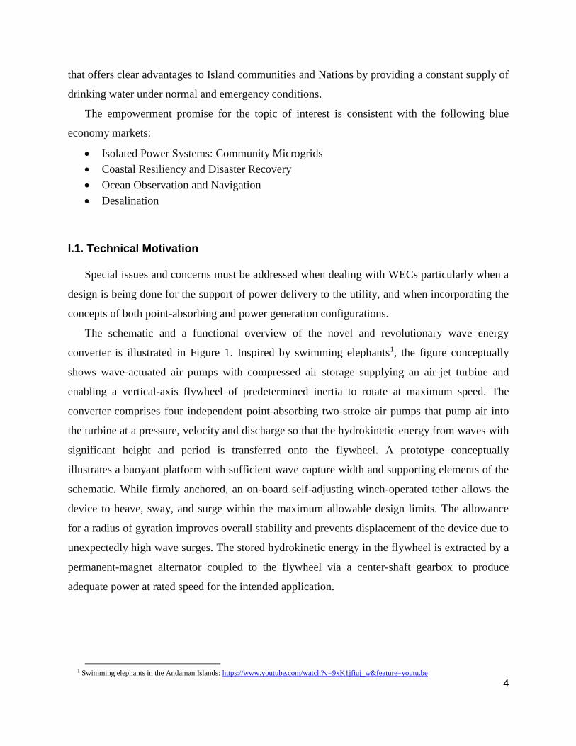
I.1. Technical Motivation
Special issues and concerns must be addressed when dealing with WECs particularly when a
design is being done for the support of power delivery to the utility, and when incorporating the
concepts of both point-absorbing and power generation configurations.
The schematic and a functional overview of the novel and revolutionary wave energy
converter is illustrated in Figure 1. Inspired by swimming elephants1, the figure conceptually
shows wave-actuated air pumps with compressed air storage supplying an air-jet turbine and
enabling a vertical-axis flywheel of predetermined inertia to rotate at maximum speed. The
converter comprises four independent point-absorbing two-stroke air pumps that pump air into
the turbine at a pressure, velocity and discharge so that the hydrokinetic energy from waves with
significant height and period is transferred onto the flywheel. A prototype conceptually
illustrates a buoyant platform with sufficient wave capture width and supporting elements of the
schematic. While firmly anchored, an on-board self-adjusting winch-operated tether allows the
device to heave, sway, and surge within the maximum allowable design limits. The allowance
for a radius of gyration improves overall stability and prevents displacement of the device due to
unexpectedly high wave surges. The stored hydrokinetic energy in the flywheel is extracted by a
permanent-magnet alternator coupled to the flywheel via a center-shaft gearbox to produce
adequate power at rated speed for the intended application.
1 Swimming elephants in the Andaman Islands: https://www.youtube.com/watch?v=9xK1jfiuj_w&feature=youtu.be
Page 6
5
Fig. 1 The Schematic, principal components, and perceived operating characteristics for the
considered wave energy converter.
I.2. Technical Approach
From Figure 1, a near-constant supply of compressed air is provided by the dual actions of an
inflated airbag. As the two-stroke pump operates, part of the air-flow is directed to inflate the
flexible airbag and store compressed air. While the airbag is expanding, the air between the
inflatable and outer cylinder is ejected under compression. In the next cycle, as the air is
discharged from the airbag and the volume is decreasing, a suction pressure causes an air-inlet
valve to open and allow air into the external cylinder. As such, the two-stroke action of the pump
act as accelerating pulses. Together the air-flow system maintains the rotational velocity of the
flywheel at a maximum.
Reliability: With four independently operating point-absorbers, the failure of one, two, or
three pumps will sustain the converter operation, albeit at a lower power output capability. The
Page 7
6
power distribution among the point-absorbers is one-fourth of the power radiated by the waves
within the capture width of the device.
Modularity: The modular design allows easy transportation to the deployment site and helps
to autonomously deploy the wave energy converter.
Scalability: The ability to build a laboratory-scale prototype for testing establishes a
benchmark for scaling laws towards a full-scale prototype design, 100kW.
Manufacturability: Advanced manufacturing allows effective use of lightweight, high-
strength composite materials that greatly enhance the buoyancy and susceptibility to the harsh
marine environment.
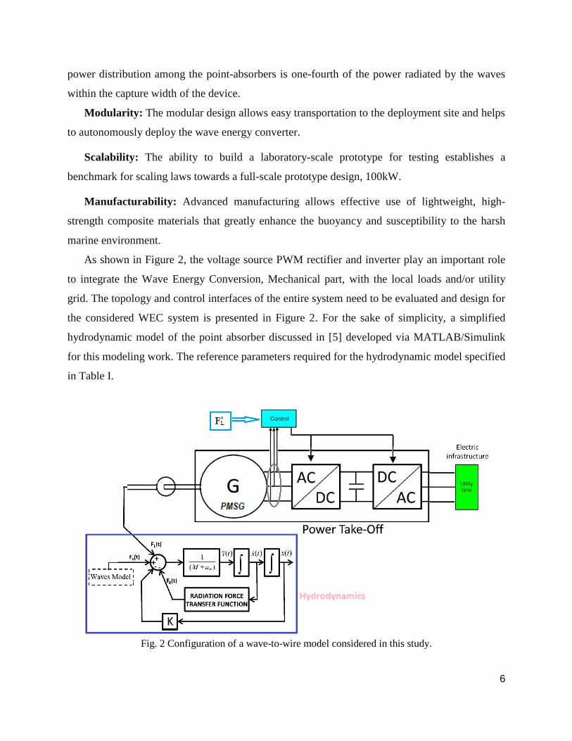
As shown in Figure 2, the voltage source PWM rectifier and inverter play an important role
to integrate the Wave Energy Conversion, Mechanical part, with the local loads and/or utility
grid. The topology and control interfaces of the entire system need to be evaluated and design for
the considered WEC system is presented in Figure 2. For the sake of simplicity, a simplified
hydrodynamic model of the point absorber discussed in [5] developed via MATLAB/Simulink
for this modeling work. The reference parameters required for the hydrodynamic model specified
in Table I.
Fig. 2 Configuration of a wave-to-wire model considered in this study.
Page 8
7
TABLE I: Main Parameters and Values Used in Simulation of Hydrodynamic Model [5]
As the first participation in this year marine competition, NMSU team focuses on topology
study and explore the generated electric power can be provided from this model, while the peak
force in the connection point could be estimated reasonably at vicinity of the design working
sea/ocean states. The preliminary outcome of this study could be used in the early design steps of
the WEC, particularly for component size and ratings, geometry of the buoy and the integration
issues.
NMSU team plans to build a 3D mock-up model and prototype as feasible for envisioned
WEC system for next year competition. This prototype could demonstrate the benefits of early
obtained results for various WEC applications such as saltwater distillation, on-shore/ off-shore
wastewater treatment plants, and provide much needed electric power to communities devastated
by bad weather.
II. Review of Point-absorber Wave Energy Harvesters
Over the last decade, due to many factors including the focus on CO2 emissions and
environmental impacts of power resources, and the realization of massive power density using
ocean waves, the development of ocean wave energy harvesting technologies is rising with
solutions achieving the prototyping of a real application stage. More than 1000 wave energy
conversion schemes patented in Japan, North America, and Europe by 2010 [6]. In spite of this
large innovative solutions and designs, WECs are normally categorized by location: shoreline,
nearshore and offshore devices; type: attenuator, point absorber and terminator; and modes of
operation: submerged pressure differential, oscillating water column, and overtopping devices
[6-8].
Page 9
8
In [9], one can find that the equivalent electric circuit theory for a WEC system is feasible to
simulate different operating conditions of an actual point absorbing for a quick assessment.
Majority of the reported studies in ocean wave energy harvesting are theoretical or missing
different designs of power take-off (PTO) system into consideration. For example, system level
analysis of all-electric PTO solutions has not fully explored in literature. Notably, the hydraulic
PTO system has recently discussed in [10], as an approximate Coulomb damping force and
applied to the equation of motion for a multi-buoy type WEC.
Solar Photovoltaic (PV) and wind resources present a relatively uniform energy flow,
however, the distinct difference of wave energy is pertaining to the wave reciprocating motion,
high energy density with slow speed and seasonal variations in heights and periods [11].
Consequently, the key challenge in designing WEC is related to an effective operation in a wide
variety of sea conditions in order to maintain an output electric power fluctuation within an
acceptable limit. This is a major requirement to be satisfied for safe integration of the produced
power to the onshore power network [5]. This aspect is a key focus of this report to verify the
performance of the proposed PTO system with the suggested point-absorber via sets of
simulation case studies to validate our ideas before lab testing.
Several WECs have been introduced and evaluated based on important properties- such as
type of PTO and prices of electricity (it is to be noted that the price is normally considered
prototypes, so the prices of the electricity are ''optimistic''). According to the existing solutions
comparison, despite substantial R&Ds, the concepts for converting the motion of the waves into
electricity still do not show any signs of converging to a single favored solution. The present
technology is barely able to present a reliable, functioning device that would be commercially
deployed. Moreover, it is not clear which alternative configuration of PTOs will prevail and how
a WEC needs to be chosen for specific locations. A significant problem arises regarding
optimizing- the WECs. All the PTO subsystems need to be taken into account to reach an
efficient operation and also the possible layout of the wave farm where the WEC will be
deployed needs to be considered.
There are three major open challenges in the current state-of-the-art WEC technologies.
Firstly, there is a need for a technology that is modular and is scalable such that the WEC can be
assembled as a plug-&-play system and deployed rapidly. Secondly, modularity offers many
Page 10
9
advantages that, while manufacturing costs can be minimized, the operation and maintenance
costs could also be substantially decreased by enabling quick replacement or repair of failed
components. Thirdly, the ease of manufacturing using advanced 3D printing, ease of assembly,
transportation, and deployment, ease of repair, and the fabrication of spare parts on demand all
contribute towards a technology that satisfies the criteria for techno-economic viability.
Besides these three expectations, which mainly deal with topologies and controls, practical
issues in WECs must also be considered. The practical issues include systematic design
methodologies to optimize overall performance than individual component and evaluations of
the advantages and limitations of power electronics converters for particular marine applications
using state-of-the-art devices and components.
III. Description of the Proposed Point Absorber and PTO System
The PTO is considered the most important aspect of harvesting power from the ocean waves
motions. The PTO mechanism is responsible of transferring the harvested mechanical energy to
electrical form.
The proposed PTO system developed using MATLAB/Simulink, which is the basis for the
model verification of all-electric PTO. This PTO consists of the following components:
- Permanent Magnet Synchronous Machine (PMSM);
- AC-DC converter (Rectifier);
- DC-AC converter (Inverter)
- DC-link Capacitor Bank;
- Brake Chopper and Dump Resistor
- Controller
The salient feature of this scheme is that there is no hydraulic or pneumatic stage inside PTO
system. The all-electric PTO shown in Figure 2 comprises the electric machine along with back-
to-back power electronics conversion units to link the generator/ wave side control to the electric
infrastructure (grid) for WEC.
The proposed point absorber is equipped with a rotating PMSG and the corresponding
controls to provide an independent controlled strategy. The power rating of electric machine is
fixed at 100 kW. By employing of a fully controlled power electronics converters interface
Page 11
10
completely decouples the electric machines from the main grid. This implies that the same
efficiency in the power extraction from the waves can be guaranteed. Using transformer for the
WEC allows the output voltage level to be compatible with the interconnection point at the local
grid side. Furthermore, in the case of designing full bi-directional power electronics converters,
the highest degree of flexibility in WEC control is ensured offering a reversed energy flow from
the grid to the point absorber. This aspect of operating condition is not investigated in this report.
From Figure 2, the wave side WEC control strategy is needed to maximize the power
extraction from the waves based on the imposed sea states and changes. The load force, FL, or
torque applied to the point absorber by the PTO is proportional to the buoy velocity as well as
buoy acceleration. This relation can be mathematically represented by [5]:
Here, BL denotes the machinery damping, and ML is the machinery added mass. Input into the
wave-to-wire model is thus either the load force or the load force parameters as given in Table I.
The first conversion stage (rectifier) is coupled through common DC-link capacitors, as
illustrated in Figure 2. The point absorber is equipped with PMSM and the second conversion
stage (inverter) connect to a DC-link to operate is considered for the PTO system. The nominal
value of the DC-link is considered as a constant voltage of 300 V. The main specifications of the
PMSM generator are nominal speed (950 in rpm) and maximum torque (800 in N.m).
The key attributes of the PWM converters are related to maximum voltage which is regulated by
DC-link control loop at the rectifier side and the speed control strategy in the inverter side. It is
found out that the inverter losses are relatively small, within 5%-10% of the total losses than the
generator.
The selected generator is a 32-pole PMSM with rotor type of salient-pole. For the detailed
modeling and control of this type of generator, we refer to [12]. It should be noted that the
reference torque is computed from WEC mechanical expressions by:
Where is the gear ratio including linear to rotational radius having the unit (1/m).
The overall view of the developed model of the WEC in Simulink is provided in Figure 3. To
evaluate the basic operating principles of the studied system and its control functionalities, case
study simulations are performed and some results are included in the following sections.
Page 12
11
Fig. 3 Developed WEC model and its control scheme in Simulink environment
The utility or grid side control is fulfilled by inverter control scheme for supplying needed
active power at the point of connection in addition to generator speed control. Although the
scheme needs the load current information, no additional sensor is required, because this
information is already needed for other control functions in the three-phase inverter system.
Wave Profile Generator
The energy profile of a sea state is often represented as a function of the frequency of the
incident waves by an energy spectrum, which can be mathematically modeled starting from one
or more parameters. In this work, the preferred analytical form of the sea state can be represented
by the frequency spectrum, S (ω) (Bretschneider spectrum) [13]:
Where Hs is the significant height of the sea state; and ω0 is the peak frequency. Figure 4
displays Bretschneider spectra for different values of the peak frequency. The time-domain wave
elevation of the actual sea waves can be represented as the super-position of sinusoidal waves at
different frequencies. Hence, the energy spectrum can be used to represent the sea by summing a
finite number of different frequency components of height and random phase.
The wave elevation due to each such wave components can be written by time-series as:
Page 13
12
Where Фn is the randomly generated offset angle for each wave component, (n=1,…N).
Fig. 4 Sea wave spectrum for various peak period, Tp (in sec) based on Bretschneider spectra.
A typical example of wave profile over time is plotted in Figure 5, where Hs is the wave
height and Te is the energy period (in sec) as defined in [13].
Fig. 5 An example of an incident wave profile of a Bretschneider spectrum with Hs=7m and Te=11sec.
Page 14
13
Preliminary Dimension Analysis of a Novel Point-absorber
In this section, initial 3D models and cylinder analysis are discussed. The WEC comprises 8
independent cylinder point-absorbing as shown in Figure 6.
Fig. 6 Schematic of eight-cylinder design
The considered sizes and dimensions for the design concept are listed as follow:
- Total diameter is 3m
- Cylinder has 0.3m diameter with 0.5m height
Basis example of piston is shown in Figure 7, in which heavy base is considered to increase
downward gravity pull.
Fig. 7 Schematic of the designed piston in horizontal view and considered piston example (right
photo)
Another option for designing cylinders is to assume possible square base structure as
presented in Figure 8. It features longer stroke and enhanced circular flow outlet for pressurized
air.
Page 15
14
Fig. 8 Schematic of the possible square-base cylinder structure
It should be emphasized that as mentioned earlier the design basis includes four independent
cylinders point-absorbing configuration as shown in Figure 9. The selected design basis offers
four larger in diameter pistons along with no central hole and water leakage.
Fig. 9 Schematic of design basis for four independent cylinders point-absorbing arrangement.
Figure 10 shows a very simple illustration of how the cylinder works. The piston is pushed
up from the force of the waves which compresses the air inside the chamber. This air is then
pressurized which spins the fan or propeller.
Page 16
15
Fig. 10 Illustration of working process for individual cylinder and piston.
The respective sizes and dimensions for this design are estimated as:
- Diameter of base: 3m
- Stroke length: 2m
- Cylinder diameter: 0.8m
- Diameter of Piston: 0.7m
It is important to mention that above dimensions are estimated and updated to try and best
maximize use of carbon fiber materials.
Page 17
16
IV. Simulation Verification of Case Studies
To verify the proposed PTO system functionality with point-absorber and its advantages, the
simulation model is developed using MATLAB/Simulink software package and the observed
results are compared against theoretical findings. The main PTO system specifications and
parameters used in the simulation are listed in Table II.
TABLE II: Main system specifications and values used in simulation
Max DC-link
voltage(V)
Peak Output AC
Current (A)
Speed PI Controller
Gains
Rectifier Switching
Frequency (kHz)
300 170 Kp=0.5, Ki=100 5
DC-link Capacitors
(mF)
Generator Nominal
Speed (rpm)
Max PTO Torque (N.m) Inverter Switching
Frequency (kHz)
1 950 800 20
Figure 11 shows the simulation waveforms in steady-state when the generator speed and
torque are maintained to their nominal values. One can notice that output phase-A current
waveform is also acceptable.
A 3-level Sinusoidal Pulse-Width Modulation (PWM)-controlled inverter with carrier
frequency of 20 kHz is operating via closed-loop control to send gating pulses to power switches.
Line-to-Line voltage waveform across inverter phase-A and phase-B is depicted in Figure 12. As
it can be seen, there are three voltage levels appear in the voltage waveform corresponding to the
chosen PWM scheme implemented for the DC-AC converter to produce high power quality
waveform. Similarly, the AC-DC power converter, rectifier, is able to generate a relatively
constant output DC voltage for the DC-bus as shown in Figure 13.
Page 19
18
(c)
Fig. 11 Simulated steady-state Generator waveforms: (a) Generator Speed, (b) Phase-A current, and (c)
Torque response.
(a)
Page 20
19
(b)
Fig. 12 Simulated (a) inverter Line-to-Line voltage waveform, and (b) Zoomed-in waveform
Fig. 13 DC-bus voltage waveform provided by the rectifier.
Page 21
20
Another testing scenario is carried out to reflect performance of the entire system with respect
to dynamic operating condition. Therefore, the operating scenario is evaluated when the driving
torque from point-absorber to the generator is reduced by 37% from nominal 800 n.m to nearly
500 n.m. It is assumed that this change happens suddenly at time instant t=0.5sec in the
simulation analysis. Generator speed and torque measurements are shown in Figure 14(a) and
14(c), respectively. Note that the observed spike of generator speed at t=0.5sec due to the applied
change is approximately 20% of the nominal speed in which could be beyond the acceptable
speed limits.
The phase-A current as presented in Figure 14(b) is reduced as expected corresponding to the
torque reduction. The inverter line voltages are showing negligible voltage ramps after t=0.5sec
for a few cycles, however, as illustrated in Figure 15, the waveform returns to the conditions
before applying torque change which is verifying an effective inverter control loop. More
importantly, the DC-link voltage controller works satisfactorily during the mentioned transient
operation to maintain the DC voltage within tolerable limits as shown in the DC-bus voltage
waveform captured in Figure 16.
(a)
Page 22
21
(b)
(c)
Fig. 14 Simulated dynamic response of the generator when torque applied to the PTO has droped by 37%
at t=0.5sec: (a) Generator speed response, (b) Current for Phase-A, and (c) Measured Torque.
Page 23
22
Fig. 15 Inverter Line-to-Line voltage waveform response when torque applied to the PTO has droped by
37% at t=0.5sec.
Fig. 16 DC-bus voltage waveform provided by the rectifier when torque applied to the PTO has droped by
37% at t=0.5sec.
Page 24
23
Finally, simulation of the buoy and PTO combined is performed under the irregular wave
condition. There is no doubt that irregular waves lead to a buoy complex motions of surge, heave
and pitch directions.
As mentioned earlier, one of the advantages of the time-domain is the ability to model sea
wave states under the excitation of irregular waves. This is done by the superposition of 𝑁
different sinusoidal regular waves (from 𝑛 = 1 to 𝑛 = 𝑁) as presented in Section III. To perform
the behavior of the PTO module under irregular sea wave condition, the high energy sea wave
profile illustrated in Figure 5 is considered. The obtained simulation results of the measured
power from generator and high energy sea state are shown in Figure 17. Furthermore, inverter
losses are also plotted in Figure 17, in which the rule of thumb of 7% losses from nominal
generated power is considered. A scaling factor of 10 is used here to easily compare the losses
with the mechanical and electrical power waveforms.
Fig. 17 The WEC system simulation waveforms for mechanical extracted power, inverter losses
(magnified by a factor of 10), and electrical output power.
Several operating scenarios have been analyzed and the obtained results are evaluated to
verify the acceptable performance of the PTO and its different subsystems. Further assessment is
Page 25
24
to be done, and comparison with promising solutions is also interesting topic and worth to
explore.
V. Summary
Over the past decade, medium-voltage power-grid tied Power Take-off (PTO) configurations
for distribution generation-based Wave Energy Converter (WEC) have been under investigation
with focus on diverse power electronics topologies and their associated controls. The effects of
hydrodynamics of point-absorber from waves conditions, sea-states should be effectively
included in the design process to increase the efficiency and reliability of any WECs with an
acceptable size of entire system. In distributed generation applications, switching frequency of
power electronics converter modules is expected to be high enough to achieve a robust control
for different load conditions and fast dynamic response, and high efficiency is a very important
requirement for emerging WEC solutions. However, in high-power medium-voltage application
the switching frequency is usually very low and limited by the switching losses of semiconductor
devices. Multilevel soft-switching techniques are very suited for medium-voltage high-power
distributed generation systems.
Different WEC systems and PTO architectures are reviewed, among these existing studies,
promising simplified modeling techniques show sufficient overall performance analysis
compared with such complex and detailed modeling cases. However, the simplified models have
one common drawback of ignoring hydrodynamics effects of point-absorber on the connected
PTO circuit and control, which leads to low reliability and too optimistic outcomes for making
recommendations of one solution over the other alternatives. The hydrodynamic model in the
simulation analysis is used with greatly simplified circuit offers prompt evaluation of the results
from system-level standpoint. However, for further investigation of the entire WEC system, the
hydrodynamics effects need to be taken into consideration.
Moreover, the control of power electronics converters (rectifier and inverter) is simple and
requires no modification on traditional Sinusoidal PWM and additional sensors for control loops.
Simulation results verified the effectiveness of the proposed PTO system and its subcomponents
for the studied point-absorber WEC.
Page 26
25
For this work, the team aim has been to accumulate enough knowledge on WEC topologies
based on point-absorber technologies to be interfaced with the proposed back-to-back PTO. For
the next year competition, we will start making 3D mock-up models for initial lab testing and
focusing on system level issues. Specifically, failure-mode analysis for PTO system at different
load and sea conditions supported by experiments will be scheduled accordingly.
VI. References
[1] LiVecchi, A., A. Copping, D. Jenne, A. Gorton, R. Preus, G. Gill, R. Robichaud, R. Green, S.
Geerlofs, S. Gore, D. Hume, W. McShane, C. Schmaus, H. Spence. 2019. Powering the Blue
Economy; Exploring Opportunities for Marine Renewable Energy in Maritime Markets. U.S.
Department of Energy, Office of Energy Efficiency and Renewable Energy. Washington, D.C.
[2] Annual Report Ocean Energy Systems. Available online: https://report2016.ocean-energy-
systems.org/ (accessed on 14 April 2021).
[3] https://www.nrel.gov/docs/fy16osti/66794.pdf
[4] D. Qiao, R. Haider, J. Yan, D. Ning, and B. Li, "Review of Wave Energy Converter and Design
of Mooring System," Sustainability, 2020, 12, 8251.
[5] E. Tedeschi, and M. Santos-Mugica, "Modeling and Control of a Wave Energy Farm Including
Energy Storage for Power Quality Enhancement: the Bimep Case Study," IEEE Trans. On Power
Syst., vol. 29, no. 3, May 2014, pp. 1489-1497.
[6] B. Drew, A. R. Plummer, M. N. Sahinkaya “A review of wave energy converter technology”,
Department of Mechanical Engineering, University of Bath, UK, 2010.
[7] B. Czech, P. Bauer, "Wave Energy Converter Concepts, Design Challenges and Classification,"
IEEE Ind. Electronics Magz., vol. 6, no. 2, June 2012, pp. 4-16.
[8] L. Yong and F. C. Lee, "Comments on Control of Wave Energy Converters," IEEE Transactions
on Control Systems Technol., , vol. 29, no. 1, January 2021, pp. 478-481.
[9] L. Hai, O. Svensson, J. Isberg, and M. Leijon, "Modelling a point absorbing wave energy
converter by the equivalent electric circuit theory: A feasibility study," Journal of Applied
Physics, vol. 117, 164901, 2015.
[10] S. J. Kim, and W. Koo, "Numerical Study on a Multibuoy-Type Wave Energy Converter With
Hydraulic PTO System Under Real Sea Conditions," IEEE Journal of Oceanic Engineering, vol.
46, no.2, April 2021. pp. 573–582.
[11] J. Prendergast, M. Li, and W. Sheng, B.G. Lee, "A Study of the Effects of Wave Spectra on
Wave Energy Conversions," IEEE Journal of Oceanic Engineering, vol. 45, no.1, January 2020.
pp. 271–283.
[12] N. Mohan, "Advanced Electric Drives: Analysis, Control and Modeling Using Simulink," Wiley,
1st edition, USA, 2014.
[13] W.H. Mitchell, "Sea Spectra Revisited," Marine Technology, vol. 36, no. 4, 1999, pp. 211–227.
Page 27
26
The Business Idea and Plan
VII. Performance Metrics
Based on the WEC concept illustrated in Figure 1, the metrics definitions and variables are
given in Figure 18 as
Characteristic Capital Expenditure (CCE) is expressed in millions of US$ that includes the
manufacturing cost, transportation and deployment costs, and all costs required for certification.
Therefore, the Average Capital Expenditure (ACE) can be calculated by
Fig. 18 Schematics and the principal components of a WEC used for basis performance metrics
Here, the sample performance metrics is followed to better understand it. By assuming
Radiated power of 33.3 kW/m and for the WEC prototype absorption power of 100kW (rated
power), the Average Climate Capture Width (ACCW) in meters can be obtained as:
Page 28
27
Thus, Capture Width is equal to 3 meters.
Characteristic Capital Expenditure (CCE) in millions of $US includes Total Surface Area,
Representative Structural Thickness, Density of the Material, Cost of Manufactured Material,
and additional costs that capture the end-to-end cost of deployment and certification.
Assume the WEC cost as One Million US$, the ACE is
It should be noted that the state-of-the-art ACE is within (1.5m-3m)/$1M
VIII. WEC Market by Technology, Application and Location
It is projected the global wave energy market to reach $107 million by 2025 showing 2.5 times
larger market compared to that of an estimated market size in 2020. The driving factors for such
a substantial growth for wave energy market is because of the growing adoption for renewable
energy generation and other applications is helping manufacturers to invest more in R&Ds effort
leading to the growth of wave energy market. Among those key factors, the power generation
segment is expected to be the most significant portion of wave energy market, by application,
during the forecast period to a keen emphasis on electrical energy generation through renewable
sources. Many business studies and reports forecasted deliveries of linear generators with length
of 2-4 meters (25 -50 kW) for offshore wave power plants in the years ahead. Another mindset is
that it can deploy wave generators which can exploit the energy of the waves in more coastal
areas, with normal wave heights of 0.6 to 1.2 meters, which will require linear generators with 10
kW of power and which will have a «stroke length» of less than 1 meter.
Considering the location of the wave energy market, near shore segment is expected to be the
largest and fastest growing market over the next 5 years. The operational efficiency of near shore
installations is found to be better than onshore facilities in many cases, giving the segment an
excellent opportunity to grow further in the future.
Page 29
28
Europe is both largest and the fastest-growing wave energy market, followed by North
America and Asia Pacific. It is expected that there will be maximum adoption and
implementation of wave energy conversion devices owing to the presence of a large number of
companies working in the research and development of wave energy converters.
Off-the-shelf components, including pistons, pumps, and power generating equipment and
hardware establish a market chain of suppliers enabling the manufacture and commercialization
of the proposed WEC concept. The market potential including a survey of potential vendors need
to be studied as part of the Techno-Economic assessment. There are immense opportunities for
island nations throughout the World to employ this concept for creating sufficient energy mix
with conventional power generating sources. Puerto Rico, and the U.S. Virgin Islands
experienced the worst power outages in U.S. history. Achieving a readiness level of TRL 5 will
allow demonstrations of the device to domestic and international aid agencies along with private
investors, venture capitalists, and entrepreneurs who seek to advance their business opportunities
for providing off-grid utility and emergency services Worldwide.
Oil & Gas companies can, for example also be customers of this concept, securing an energy
source for its oil floating platforms. However, to start with the WC farms will be near the coast
in cooperation with the usual Electric Works customers.
The concept fits very well in alignment with the coming sea-wind farms offshore, as our
buoy and generators can be deployed in between the major sea-wind turbines that are relatively
far apart (and where an expensive electric distribution network has already been deployed on
land) without our buoys will be in the way of supply boats servicing mission to the sea-wind
turbines - because the buoys can immerse on the signal when the service will enter boats in the
area.