Purdue University Purdue e-Pubs Purdue Energetics Research Center Articles Purdue Energetics Research Center 5-2012 Feasibility Study and Demonstration of an Aluminum and Ice Solid Propellant Timothee L. Pourpoint Purdue University, [email protected]Tyler D. Wood Purdue University Mark A. Pfeil Purdue University John Tsohas Purdue University Steven F. Son Purdue University Follow this and additional works at: hps://docs.lib.purdue.edu/perc_articles is document has been made available through Purdue e-Pubs, a service of the Purdue University Libraries. Please contact [email protected] for additional information. Recommended Citation Timothee L. Pourpoint, Tyler D. Wood, Mark A. Pfeil, John Tsohas, and Steven F. Son, “Feasibility Study and Demonstration of an Aluminum and Ice Solid Propellant,” International Journal of Aerospace Engineering, vol. 2012, Article ID 874076, 11 pages, 2012. doi:10.1155/2012/874076
Transcript
Purdue UniversityPurdue e-Pubs
Purdue Energetics Research Center Articles Purdue Energetics Research Center
5-2012
Feasibility Study and Demonstration of anAluminum and Ice Solid PropellantTimothee L. PourpointPurdue University, [email protected]
Tyler D. WoodPurdue University
Mark A. PfeilPurdue University
John TsohasPurdue University
Steven F. SonPurdue University
Follow this and additional works at: https://docs.lib.purdue.edu/perc_articles
This document has been made available through Purdue e-Pubs, a service of the Purdue University Libraries. Please contact [email protected] foradditional information.
Recommended CitationTimothee L. Pourpoint, Tyler D. Wood, Mark A. Pfeil, John Tsohas, and Steven F. Son, “Feasibility Study and Demonstration of anAluminum and Ice Solid Propellant,” International Journal of Aerospace Engineering, vol. 2012, Article ID 874076, 11 pages, 2012.doi:10.1155/2012/874076
Aluminum-water reactions have been proposed and studied for several decades for underwater propulsion systems andapplications requiring hydrogen generation. Aluminum and water have also been proposed as a frozen propellant, and there havebeen proposals for other refrigerated propellants that could be mixed, frozen in situ, and used as solid propellants. However,little work has been done to determine the feasibility of these concepts. With the recent availability of nanoscale aluminum,a simple binary formulation with water is now feasible. Nanosized aluminum has a lower ignition temperature than micron-sized aluminum particles, partly due to its high surface area, and burning times are much faster than micron aluminum. Frozennanoscale aluminum and water mixtures are stable, as well as insensitive to electrostatic discharge, impact, and shock. Here wereport a study of the feasibility of an nAl-ice propellant in small-scale rocket experiments. The focus here is not to developan optimized propellant; however improved formulations are possible. Several static motor experiments have been conducted,including using a flight-weight casing. The flight weight casing was used in the first sounding rocket test of an aluminum-icepropellant, establishing a proof of concept for simple propellant mixtures making use of nanoscale particles.
1. Introduction
Aluminum powder is a common ingredient in conventionalsolid rocket propellants. It is used to increase specificimpulse, Isp, as well as stability. The properties and recentavailability of nanoscale aluminum (nAl) have motivatedrecent efforts in new solid propellant formulations. Forexample, Kuo et al. [1] discussed the potential use ofnanosized powders for rocket propulsion in a recent paper.Many of the potential advantages listed for these particles areshort ignition delay, fast burning times, and the possibilityto act as an energetic gelling agent. Using nAl has beenshown to produce a significant increase in performance withconventional solid propellants [2, 3]. Researchers showedthat replacing 50 μm particles with the same amount ofnominally 100 nm particles in AP-based propellants couldresult in a burning rate increase of up to 100% [4]. Mostof these characteristics can be attributed to the high-specificsurface area of the nanoscale particles [1, 5]. The possible
drawbacks of nAl are the reduction in active aluminumcontent, electrostatic discharge (ESD) sensitivity when dry,and poor rheological properties. Other research has beenconducted pairing this increased reactivity of nAl with lessreactive oxidizers such as water in addition to conventionaloxidizers [6, 7]. Aluminum and water propellants may proveto be suited for deep space exploration in that propellantscould be made in situ from available water and aluminum.Also, the products of this propellant, mainly H2 and Al2O3,are relatively nontoxic, making it a “greener” propellant[8, 9].
The objectives of this paper are to present results ofnAl/ice (ALICE) small-scale static experiments, along withthe launch of a sounding rocket powered by ALICE. Anotherobjective was to develop larger scale (kilogram scale) mixingprocedures that produce a consistent material. A classicalmixer and a newly available Resodyn mixer were considered.The burning rate was characterized for these propellants in
2 International Journal of Aerospace Engineering
a strand burner. Results of the static test firings are alsocompared against internal ballistic predictions.
2. Background
While bulk commercial nAl has only recently been devel-oped, the water-aluminum reaction received attention asearly as the 1940s. In 1942, Rasor and Portland [10] fileda patent, which proposed to use seawater and aluminum topropel a submarine. While thermodynamically this reactionwould be viable, the kinetics of the available aluminumwould not yield complete reaction. This was evident by workdone by Elgert and Brown [11] who used U235 to melt thealuminum but could only react 0.2% of the aluminum, eventhough temperatures reached ∼1200◦C. Even work done byLeibowitz and Mishler [12], who tried igniting aluminumwith a laser, found that if the melting temperature of thealuminum oxide was not reached, ignition would not occur.
Several studies investigated the use of micron-sized Alpowders with water for underwater propulsion [13, 14].In 2004, Ingenito and Bruno [8] also published a paperdiscussing the potential uses for an aluminum-water mixturefor space propulsion. Using the NASA CEA equilibriumcode, they calculated the theoretical specific impulse valuesof mixtures over a range of oxidizer-to-fuel (O/F) ratios.Assuming an expansion ratio of 100, the calculated vacuumIsp at an O/F of ∼1.2 is greater than 300 s and higher thanthat of most solid propellants [15]. Ingenito and Brunoalso proposed the idea of adding hydrogen peroxide (H2O2)to increase performance. Indeed, many other propellantformulations are possible [8].
Nanoscale aluminum can dramatically increase the reac-tion rates of aluminum and water. Ivanov et al. [16] reportedthe earliest combustion work with stoichiometric mixtures ofnAl and water. They reported needing 3% polyacrylamide tothicken (or gel) the water and enable the nAl-water reaction.In 2006, Risha et al. [17] reported, for the first time, thecombustion of nAl and water without the use of a gellingagent. Risha’s successful results were likely attributable to ahigher surface area nAl than previously used. Risha et al.found that stoichiometric mixtures of nAl-water propellanthave a pressure dependence of around 0.47 and have densitiesof around 1.5 g/cm3. While the burning rate for a fuel-lean mixture was lower than a stoichiometric mixture, thepressure exponents were similar. This suggests that thepropellant has the same pressure dependence, regardless ofthe amount of excess water.
Upon production by manufacturers, such as NovacentrixInc. and Argonide Corp, aluminum powders form a pas-sivation layer of alumina. Even with this passivation layer,nAl-water can have a short shelf life, on the order of weeks,when exposed to moist air due to the high affinity of nAlfor oxygen [18]. The inert alumina shell adversely affects theperformance of the mixture [5, 17]. Due to the smaller size ofthe aluminum particles (from micron to nano), the aluminalayer accounts for more of the mass in nAl particles. Dokhanet al. [19] estimate that active aluminum content of micronaluminum is 99.5% or better, while the active aluminum
content of passivated nAl typically ranges from 50% to 95%[18, 20, 21].
Franson et al. [22] performed perhaps the first work onthe implementation of ALICE in a rocket motor configu-ration. The outer diameter of the grain was 86 mm, withan inner perforation diameter of 60 mm and a length of157 mm. The total mass of the grain using a combination ofmicron and nanoscale aluminum was 550 g. Postinspectionof the motor revealed large amounts of alumina residues inthe chambers. Analysis of the slag showed that ∼17% of theinitial aluminum did not participate in the reaction. Thishelped explain the observed maximum pressure of 1.6 MPacompared to the 3 MPa expected value.
In previous work by our group, we examined theaging characteristics of aluminum and water mixtures. Onemethod to increase shelf life is to freeze the aluminumwater mixture to form ALICE. Sippel et al. [18] showedthat nAl and water stored at −25◦C retained its originalactive aluminum content after 40 days, following a procedureby Cliff et al. [21]. This was a significant increase fromthe previous findings that had a value less then 10% afterthe same time period in liquid water. In addition, Sippelet al. found that over the course of six months, the activealuminum content was unchanged within the uncertainty ofthe measurement [18].
Safety testing was also performed on the experimentalpropellant. Impact sensitivity testing showed that a mixtureof frozen nAl using nominally 80 nm powder and water(ALICE) has a drop height greater than the capacity ofthe experiment apparatus (>2.2 meters), while dry 200 μmAP has a drop height of 38.5 cm. ESD testing showed thatstoichiometric ALICE mixtures have an energy thresholdgreater than 1.5 J, over one thousand times the amount ofenergy typically released in a human ESD event. Shock sen-sitivity was performed to determine whether the propellantwould propagate a detonation wave. The results displayed thestability of the frozen propellant using 80 nm nAl, with noindication of damage to a witness plate [18].
3. Mixing Techniques
Early mixtures in this work were mixed by hand or usinga Ross DPM-1Q dual planetary mixer (Charles Ross & SonCompany, Hauppauge, New York). However, inconstanciesin mixing and packing densities motivated other approaches.A Resodyn LabRAM resonating mixer (Resodyn AcousticMixer Inc., Butte, Montana) was ultimately selected to mixthe ALICE propellant. The LabRAM mixer is designed tooperate at the resonant frequency of the system being mixed,using the user-specified intensity (ranging from 0 to 100)[23]. The density and viscosity of the system will change as itmixes causing the resonant frequency of the system and theenergy put into the mixture (measured by the accelerationlevel) to change with time.
The changes in acceleration and frequency provide im-portant information related to the completeness of themixing process. In a typical mix, the frequency of the mixerincreases initially and then drops, while the acceleration
International Journal of Aerospace Engineering 3
60.7
60.8
60.9
61
61.1
61.2
61.3
61.4
61.5
Freq
uen
cy (
Hz)
0 100 200 300 400 5000
10
20
30
40
50
60
70
80
90
Time (s)
Acc
eler
atio
n (
G)
AccelerationFrequency
(a)
60.6
60.65
60.7
60.75
60.8
60.85
60.9
60.95
61
Freq
uen
cy (
Hz)
0 50 100 150 200 2500
10
20
30
40
50
60
70
80
90
100
Time (s)
Acc
eler
atio
n (
G)
AccelerationFrequency
(b)
Figure 1: Traces from the Resodyn mixer: (a) acceleration and frequency of consecutive multiple mixing cycles; (b) acceleration andfrequency of single mixing cycle of near constant intensity.
(a) (b) (c)
Figure 2: Images of various stages of mixing in 7.6 cm (3′′) diameter jar: (a) mixing consistency after first cycle; (b) mixing consistency aftersecond cycle; (c) mixing consistency after final cycle.
exhibits a general continual increase. These fluctuationsoccur due to the changing mixture properties throughoutmixing (Figure 1).
As shown in Figure 2(a), ALICE starts out as a mixtureof deionized water and 80 nm aluminum powder fromNovacentrix Inc. (Product no.: M2666, properties listedin Table 1). Upon mixing, the mixture begins to formclumps until it becomes a uniform paste-like substance(Figure 2(b)). The properties of the propellant then reach auniform state; in other words the propellant is fully mixed,when the acceleration and the frequency level off for a periodof time (Figure 2(c)).
4. Burning Rate MeasurementsTechnique and Results
In previous work with the Ross dual planetary mixer,stoichiometric mixtures proved to be too viscous for thesize of nAl used. The propellant became too thick tomix effectively with the Ross mixer. This viscous behavior
prompted the final ALICE mixtures to be fuel-lean witha target equivalence ratio, φ, of 0.75. Fuel-lean mixtureshad an overall decrease in burning rate when comparedto stoichiometric mixtures, but Risha et al. show similarpressure exponents for both the fuel-lean and stoichiometricmixtures [17].
Mixing procedures used with the Resodyn mixer evolvedand improved throughout the project. Initial procedureswere developed based on the equivalence ratio of 0.75.However, safety concerns related to the reactive nature of thenanoaluminum powder led to the decision of passivating thepowder in air for two days prior to mixing. This passivationstep lowered the active aluminum content by about 4%leading to an equivalence ratio closer to 0.71 and providingfor a less reactive propellant. Again, the formulation studiedhere is far from optimum.
Strand burn experiments were performed using materialfrom each mixing batch used to produce static fire grains.Each strand consisted of an 8 mm ID × 5 cm L tube filledwith the φ = 0.71 mixture. The frozen strand samples were
Per BET analysis as reported by Mang et al. [24].(b)Per Small Angle Scattering analysis as reported by Mang et al. [24].(c)Per SEM and TEM images analysis as reported by Sippel [25].(d)Calculated from BET surface area and reported by Sippel [25].
3 4 5 6 7 8 9 10 20 300.4
0.6
0.8
1
3
5
7
Pressure (MPa)
Bu
rnin
g ra
te (
cm/s
)
rb = 0.70274P(0.57019)
R2 = 0.71033
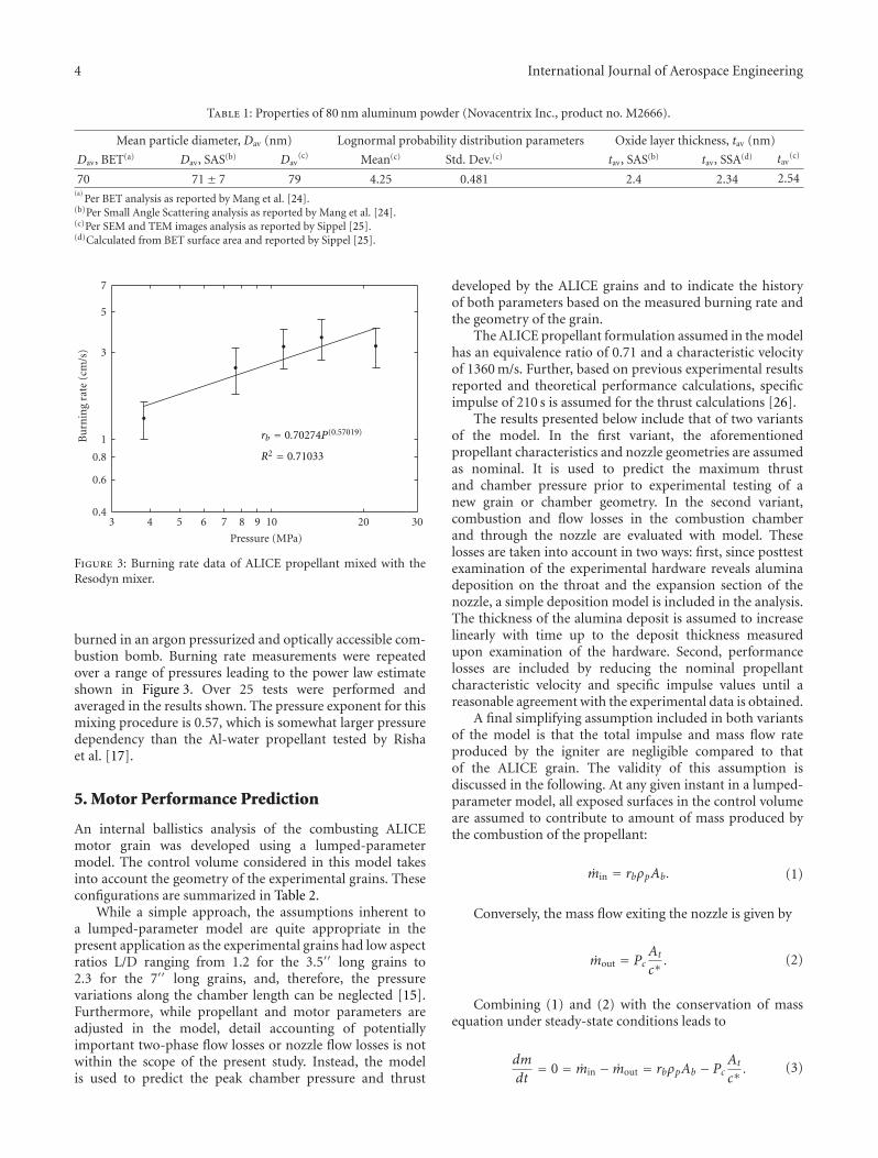
Figure 3: Burning rate data of ALICE propellant mixed with theResodyn mixer.
burned in an argon pressurized and optically accessible com-bustion bomb. Burning rate measurements were repeatedover a range of pressures leading to the power law estimateshown in Figure 3. Over 25 tests were performed andaveraged in the results shown. The pressure exponent for thismixing procedure is 0.57, which is somewhat larger pressuredependency than the Al-water propellant tested by Rishaet al. [17].
5. Motor Performance Prediction
An internal ballistics analysis of the combusting ALICEmotor grain was developed using a lumped-parametermodel. The control volume considered in this model takesinto account the geometry of the experimental grains. Theseconfigurations are summarized in Table 2.
While a simple approach, the assumptions inherent toa lumped-parameter model are quite appropriate in thepresent application as the experimental grains had low aspectratios L/D ranging from 1.2 for the 3.5′′ long grains to2.3 for the 7′′ long grains, and, therefore, the pressurevariations along the chamber length can be neglected [15].Furthermore, while propellant and motor parameters areadjusted in the model, detail accounting of potentiallyimportant two-phase flow losses or nozzle flow losses is notwithin the scope of the present study. Instead, the modelis used to predict the peak chamber pressure and thrust
developed by the ALICE grains and to indicate the historyof both parameters based on the measured burning rate andthe geometry of the grain.
The ALICE propellant formulation assumed in the modelhas an equivalence ratio of 0.71 and a characteristic velocityof 1360 m/s. Further, based on previous experimental resultsreported and theoretical performance calculations, specificimpulse of 210 s is assumed for the thrust calculations [26].
The results presented below include that of two variantsof the model. In the first variant, the aforementionedpropellant characteristics and nozzle geometries are assumedas nominal. It is used to predict the maximum thrustand chamber pressure prior to experimental testing of anew grain or chamber geometry. In the second variant,combustion and flow losses in the combustion chamberand through the nozzle are evaluated with model. Theselosses are taken into account in two ways: first, since posttestexamination of the experimental hardware reveals aluminadeposition on the throat and the expansion section of thenozzle, a simple deposition model is included in the analysis.The thickness of the alumina deposit is assumed to increaselinearly with time up to the deposit thickness measuredupon examination of the hardware. Second, performancelosses are included by reducing the nominal propellantcharacteristic velocity and specific impulse values until areasonable agreement with the experimental data is obtained.
A final simplifying assumption included in both variantsof the model is that the total impulse and mass flow rateproduced by the igniter are negligible compared to thatof the ALICE grain. The validity of this assumption isdiscussed in the following. At any given instant in a lumped-parameter model, all exposed surfaces in the control volumeare assumed to contribute to amount of mass produced bythe combustion of the propellant:
min = rbρpAb. (1)
Conversely, the mass flow exiting the nozzle is given by
mout = PcAt
c∗. (2)
Combining (1) and (2) with the conservation of massequation under steady-state conditions leads to
Equation (3) can then be solved for the chamber pressureusing St-Robert’s burning rate law, rb = aPc
n:
Pc =(aρpAbc∗
At
)1/(1−n)
. (4)
Since neither end of the grain is inhibited, the ALICEgrain burning surface area is a function of the grain outerand inner bore diameter and the grain length as given by
Ab = 2πRiL + 2(π
4(2Ro)2 − π
4(2Ri)
2)
, (5)
with both Ri and L functions of the web thickness consumednormal to the local burn surface. The web thickness, W , cantherefore be defined as the integral of the burning rate historyas given by
W =∫ tb
orb(t)dt. (6)
The theoretical mass flow rate and thrust can then becalculated based on (1) or (2) and
F = g · Isp · min. (7)
Both variants of the lumped parameter model incorpo-rate (1) to (7) using an Euler numerical integration methodwith an adequately small time step (typically 1 ms). Thesecond model variant reflects the previously mentionedperformance losses and the alumina deposition on the nozzleaccording to (8):
Dt = Dt − 2εdt, (8)
where ε is the thickness of the alumina deposit measuredaround the circumference of the nozzle throat. The chamberpressure and thrust profiles calculated with both variants ofthe model are shown in Table 3 and Figure 5 for a 5′′ longALICE grains.
As shown in Table 3, a peak chamber pressure of∼14.5 MPa is calculated with both variants of the model.However, the peak pressure obtained with the second variantfollows a longer chamber pressurization period and occurs aquarter of a second later than with the first variant (Figure 5).This delay is a result of the reduced characteristic velocity,assumed to be 85% of nominal in the second model variant.The peak pressures calculated with both variants are almostidentical as a result of the assumed alumina depositionmodel.
Also shown in Table 3 is the reduction in peak thrustfrom ∼2 to ∼1.78 kN from the first to the second variant ofthe model. This reduction is the result of the lower specificimpulse value assumed in the second variant of the model.
6. ALICE Battleship StaticThrust Stand Experiments
Several static rocket tests were conducted in the PurdueUniversity Propulsion laboratory. The test cell for the statictests has a remote control room from which experiments aremonitored and initiated. Pressure and thrust are recordedusing LabView, and a 16-bit National Instruments, 32channel data acquisition system. At least two video camerasare used to observe and record the experiments. One cameramonitors the outside where the plume is expelled, andanother high-speed camera, recording at 300 fps, monitorsthe side profile of the exhaust plume.
Based on the strand burn tests, the ALICE propellantcombustion does not perform well at pressures below 7 MPa;therefore a thick steel “battleship” motor casing was usedinitially (see Figure 4). This casing was sized to withstandinternal pressures up to 35 MPa. However, constraints in thedesign of the flight-weight casing influenced the operatingpressure of ALICE to be below 20 MPa. To eliminate anadditional variable between the battleship tests and theflight-weight tests, the same bolts were selected to secure theALICE motor assembly together. These bolts are designedto fail around 22 MPa, so overpressurization does not resultin the failure of the casing. With the anticipation thatvariations in mixing and casting will affect performance, thenozzle throat diameter was varied to provide a peak chamberpressure of 10–14 MPa.
The battleship casing was attached horizontally to ametal stand frame. The metal framing is attached to apair of flexures, which transfers the thrust to a 4.5 kNload cell (Interface, Scottsdale, Arizona). Chamber pressureis measured using two PMP 1260 diaphragm pressuretransducers, (Druck, GE Electrics, Billerica, MA) with a0.25% full-scale accuracy.
Following a few experimental tests with various ignitermotor sizes, the igniter of choice in all test configurationswas a commercially available Aerotech H180 motor [27].A summary of the motor specifications of interest in thepresent study is provided in Table 4. The reported ISP of 178 sis not unexpected for small motors such as these. As listedin Table 4, the Aerotech H180 motor has a total impulse of
6 International Journal of Aerospace Engineering
Table 3: Modeling summary for 5′′ long grain.
Model assumptions Total impulse (N-s) Peak Pc (MPa) Peak thrust (kN)
No losses for 5′′ long grain 1484 14.68 1.98
With deposit and losses for 5′′ long grain 1336 14.82 1.78
Table 4: Aerotech H180 motor specifications [27].
Parameter Value Unit
Outer diameter 29.0 mm
Total length 23.8 cm
Total weight 252 g
Propellant weight 124 g
Average thrust 180.0 N
Maximum thrust 228.5 N
Total impulse 217.7 N-s
Burn time 1.3 s
Isp 178 s
Figure 4: Photograph of the battleship motor casing for 3′′
diameter propellant grains.
218 N-s or about 15% of the total impulse predicted withthe first variant of the lumped parameter model for a 5′′
long ALICE grain (Table 3). While a smaller igniter wouldbe highly desirable, the selected igniter size was necessary forreliable and fast ignition of the ALICE formulation evaluatedin the study.
Several runs were performed with the battleship motor.Initial runs started with 3.5′′ long grains. The results ofthese experiments are not presented herein for conciseness.Following three successful runs with the 3.5′′ long grains,the length of the grain was increased to 5′′ to provide morethrust and better approximate the scale required for thesounding rocket. The experimental results of the two runsperformed with 5′′ long grains (Tests 4 and 5) are presentedand compared with the modeling results in Figure 5 andTable 5.
Although the two tests are not precisely replicated,there are several key features to note. First, the length andpacking densities of both 5′′ long grains varied by 2.3%and 4.8%, respectively, with the first 5′′-class grain about0.25 inches longer than the second one. Second, while
0 0.2 0.4 0.6 0.8 1 1.2 1.4 1.5048
1216
Time (s)
C
ham
ber
pr
essu
re (
MPa
)
0 0.2 0.4 0.6 0.8 1 1.2 1.4 1.50
0.51
1.52
Time (s)
Th
rust
(lb
f)Model (no deposit, no losses)Model (deposit and losses)
Experimental data test 4Experimental data test 5
a = 0.7, n = 0.57, Lgrain = 5
a = 0.7, n = 0.57, Lgrain = 5, 0 inhibited side
, 0 inhibited side
Figure 5: Comparison of 5′′ long ALICE motor tests with lumpedparameter models.
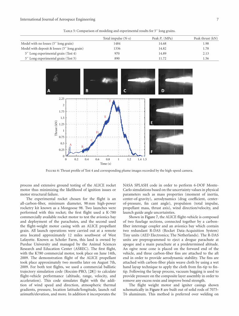
aluminum agglomeration on the nozzle or variations incasting could explain the differences in peak pressure, theexperimental peak pressures and peak thrusts compare wellwith the modeling results thus providing an increased levelof confidence for performance prediction of longer grains.The experimental and modeling results obtained for the 5′′-class grains are provided in Table 5 including the calculatedtotal impulse values which are of particular interest for thesounding rocket trajectory predictions.
Shown on Figure 6 is the recorded thrust profile forTest 4 and images of the plume at selected time stampsduring the burn. The first picture (Figure 6(A)) is the startof the igniter flame and initial chamber pressurization. Asthe H-180 igniter motor burns, gases expand in the ALICEcasing and exit the nozzle as a dark smoke. Based on therecorded data (pressure and thrust), it is believed that ALICEbegins to burn in the second picture (Figure 6(B)). Thisis evident from the sudden oscillatory change in thrustfrom the load cell, that has been consistent throughout thebattleship tests. As the pressure increases further, the flamecontinues to increase in size until the peak pressure is reached(Figures 6(B) to 6(F)). The pressure and thrust decay rapidlyfollowing the consumption of the ALICE grain.
7. Rocket Design and Launch
The demonstration flight of the ALICE propellant with anunguided experimental rocket was a proof of concept formore advanced rockets using similar nanoenergetic material-based propellants. The flight followed a rigorous design
International Journal of Aerospace Engineering 7
Table 5: Comparison of modeling and experimental results for 5′′ long grains.
Total impulse (N-s) Peak Pc (MPa) Peak thrust (kN)
Model with no losses (5′′ long grain) 1484 14.68 1.98
Model with deposit & losses (5′′ long grain) 1336 14.82 1.78
5′′ Long experimental grain (Test 4) 970 14.89 2.13
5′′ Long experimental grain (Test 5) 890 11.72 1.56
2.25
2
1.75
1.5
1.25
1
0.75
0.5
0.25
AB
C
D
E
F
0
Th
rust
(kN
)
0 0.2 0.4 0.6 0.8 1 1.2 1.4 1.5
Time (s)
Figure 6: Thrust profile of Test 4 and corresponding plume images recorded by the high-speed camera.
process and extensive ground testing of the ALICE rocketmotor thus minimizing the likelihood of ignition issues ormotor structural failure.
The experimental rocket chosen for the flight is anall-carbon-fiber, minimum diameter, 98 mm high-powerrocketry kit known as a Mongoose 98. Two launches wereperformed with this rocket; the first flight used a K-780commercially available rocket motor to test the avionics bayand deployment of the parachutes, and the second usedthe flight-weight motor casing with an ALICE propellantgrain. All launch operations were carried out at a remotearea located approximately 12 miles southwest of WestLafayette. Known as Scholer Farm, this land is owned byPurdue University and managed by the Animal SciencesResearch and Education Center (ASREC). The first flight,with the K780 commercial motor, took place on June 14th,2009. The demonstration flight of the ALICE propellanttook place approximately two months later on August 7th,2009. For both test flights, we used a commercial ballistictrajectory simulation code (Rocsim-PRO, [28]) to calculateflight-vehicle performance (altitude, range, velocity, andacceleration). This code simulates flight with the addi-tion of wind speed and direction, atmospheric thermalgradients, pressure, location latitude/longitude, launch railazimuth/elevation, and more. In addition it incorporates the
NASA SPLASH code in order to perform 6-DOF Monte-Carlo simulations based on the uncertainty values in physicalparameters such as mass properties (moment of inertia,center-of-gravity), aerodynamics (drag coefficient, center-of-pressure, fin cant angle), propulsion (total impulse,propellant mass, thrust axis), wind direction/velocity, andlaunch guide angle uncertainties.
Shown in Figure 7, the ALICE flight-vehicle is composedof two fuselage sections, connected together by a carbon-fiber interstage coupler and an avionics bay which containtwo redundant R-DAS (Rocket Data-Acquisition System)Tiny units (AED Electronics; The Netherlands). The R-DASunits are preprogrammed to eject a drogue parachute atapogee and a main parachute at a predetermined altitude.An ogive nose cone is placed on the forward end of thevehicle, and three carbon-fiber fins are attached to the aftend in order to provide aerodynamic stability. The fins areattached with carbon-fiber plain weave cloth by using a wethand layup technique to apply the cloth from fin-tip to fin-tip. Following the layup process, vacuum bagging is used toprovide pressure on the composite layer assembly in order toremove any excess resin and improve bond strength.
The flight weight motor and igniter casings shownschematically in Figure 8 are built out of solid rods of 7075-T6 aluminum. This method is preferred over welding on
8 International Journal of Aerospace Engineering
(a) (b)
Figure 7: Images of the sounding rocket: (a) altimeter bay with RDAS units; (b) exploded view of Mongoose 98 Rocket. The entire length ofthe assembled rocket is about 8 feet 6 inches and the outside diameter is 4′′.
Flight-weight casing
ALICEgrain
Igniterpropellant
Graphitenozzle
Figure 8: Schematic of the flight-weight motor casing.
flanges to the end of the casing, which could potentiallycause changes in the mechanical properties of the aluminum.Bolts are threaded into steel threaded inserts located in thealuminum flange at the aft end of the motor casing. Thesesteel inserts help to distribute the load evenly over the lengthof the thread. The bolts are the same ones used on thebattleship motor, which were selected to fail at 22 MPa. Theresults of a structural analysis of the flight-weight motorusing a 3D ProMechanica model with a solid mesh of 3512elements and an 18 MPa internal pressure load lead to afailure index of 0.29 based on the tensile yield strength ofaluminum 7075-T6 of 500 MPa. Upon completion of thecasing, the vessel was hydrotested for several minutes at apressure of 14 MPa. Passing this test allowed for the first statictest with the ALICE propellant.
Two static fire tests were conducted with the flight-weight hardware prior to launch. The first test (Test no. 6in Table 2) was performed with the horizontal configurationestablished with the battleship motor. The last static testprior to launch (Test no. 7 in Table 2) was performed withthe motor installed vertically to assess how the grain andalumina slag would behave under the effects of gravity.These concerns ranged from questions on whether the grainwould become dislodged from the walls of the phenolic tubeand slide toward the nozzle or if the alumina slag wouldclog the nozzle. This vertical test was conducted using thesame Aerotech H180 igniter as in prior tests. The grainwas slightly longer, from 6.75′′ to 7′′, compared to theprevious horizontal test but with a nearly identical packingdensity (within 2.2%). Figure 9 displays the experimental
0 0.2 0.4 0.6 0.8 1 1.2 1.4 1.50
4
8
12
Time (s)
Ch
ambe
rpr
essu
re (
MP
a)
0 0.2 0.4 0.6 0.8 1 1.2 1.4 1.50
0.51
1.52
2.5
Time (s)
Th
rust
(kN
)
Model (no deposit, no losses)Model (deposit and losses)Experimental data test 6
a = 0.7, n = 0.57, Lgrain = 6.75
a = 0.7, n = 0.57, Lgrain = 6.75
, 0 inhibited side
, 0 inhibited side
Figure 9: Comparison of 7′′ long ALICE motor tests with lumpedparameter models.
data of the vertical test and the predictions obtained withthe performance prediction model. Using the previouslydescribed simplifying assumptions for alumina deposition,characteristic velocity and specific impulse losses, the secondvariant of the model reflects the progressive nature of thegrain burning but overpredicts the peak chamber pressure.
Based on the thrust profile from the hot-fire testperformed with the 7′′ long ALICE grain, as well as the newflight-weight motor design, the Rocsim-PRO simulationspredicted that the 30 lb flight vehicle would depart the launchrail in 0.9 seconds, achieving a velocity of∼20 m/s at rail exit.The simulations also predicted a maximum acceleration of16 G’s, maximum velocity of ∼300 km/h (Mach 0.24), and anominal altitude of ∼365 m under no wind conditions.
Several constraints limited the achievable altitude withthe current ALICE powered rocket. First, the combustionand flow losses observed during the last six static testfirings lead to total impulse values of about 60% thatof the predicted values. These losses are being addressedin ongoing work with improved propellant formulations
International Journal of Aerospace Engineering 9
(a) (b) (c)
Figure 10: Images from the ALICE flight test: rocket on launch platform (a), ignition of the ALICE propellant (b), and rocket in flight (c).
0
0.1
0.2
0.3
0.4
0.5
0.6
Mac
h n
um
ber
−30
−20
−10
0
10
20
30
Acc
eler
atio
n (
G)
0 2 4 6 8 10 120
200
400
600
800
1000
1200
1400
Time (s)
Alt
itu
de (
ft)
AltitudeMach numberAcceleration
Apogee
Max velocity/motor burnout
Maximum
Coast phase
acceleration
Figure 11: R-DAS flight-data from test launch of the flight vehiclepowered by the ALICE motor.
including additives and alternative formulations to achievehigher specific impulse and lower the alumina content ofthe products. Second, the flight-weight casing for the ALICEpropellant had to sustain pressures up to 14 MPa requiringthicker walls, thus increasing vehicle weight compared to atraditional SRM. In addition, the energy required for ignitingthe current ALICE propellant formulation is significantlyhigher than that required for a standard solid propellant.This leads to added weight for an igniter casing and aninterface with the ALICE casing capable of sustaining highpressures and designed in such a way that the combustiongases do not impact the aluminum walls. Weights werealso added just below the nose cone to yield a higherstability margin. While designed for flight with safety factorsaround 1.5, the heavier casing reduced the maximum altitudeachievable with the rocket. Finally, the burning rate of the
current ALICE formulation is on the order of 2.5 cm/s at thenominal operating pressure of 10 MPa. This high burningrate means that a larger web thickness is required to sustainthe ALICE combustion over sufficiently long durations.In turn, larger grains require heavier casings. The currentdesign is a trade-off between the aforementioned constraints.Further improvements of the propellant formulation shouldaddress these constraints, thus reducing the weight of theflight-weight casing in an effort to achieve better flightperformance.
The ALICE demonstration flight took place of a fairlycool (∼21◦C ambient temperature) and calm (∼3 km/h windat launch site) day.
Figure 10 shows the ALICE vehicle on the stand ready fortakeoff (left), soon after ignition (middle), and flying underALICE soon after it cleared the launch tower (right).
The rocket coasted after the grain was depleted andreached a peak altitude of ∼394 m (1292 ft). This altitude isvery close to the estimate of 365 m (1200 ft) obtained fromRocsim-PRO assuming no wind. The data recorded from theR-DAS is shown in Figure 11.
This close agreement between recorded flight data andpredictions indicates that the thrust profile and thrustmagnitude experienced during flight were very similar tothose recorded on the ground with the flight hardware.Similarly, it is observed that the peak Isp of 210 s calculatedfrom the ground test data is a good estimate for the flight Isp.
8. Conclusions
We have shown that refrigerated solid propellants can beused for rocket motors, and the ALICE propellant has shownpromise as a rocket propellant in static test firings. Six small-scale static experiments have shown consistent results whencompared to the prediction codes. Although this currentpropellant formulation is far from optimized, improvementsin the mixing procedure have produced a consistent and
10 International Journal of Aerospace Engineering
homogeneous propellant. While the performance of ALICEis too low for practical use, the knowledge gained throughformulating and experimenting with nanoscale particles ina simple mixture is of great interest for ongoing researchactivities on advanced propellants.
An internal ballistic model developed to support theexperiments provides a simplified account of a complexseries of events within the igniter and the main combustionchamber. The model is based on measured burning rateparameters and exact grain geometries tested at the PurduePropulsion Laboratories. Perturbations to the model canbe introduced to reflect the reduction of the nozzle throatdiameter due to alumina deposition and to take into accountlosses in the combustion chamber and the nozzle. While themodel overpredicts the total impulse of the ALICE propellantgrains, it is a useful tool for peak chamber pressure andthrust predictions. Finally, based on consistency betweenmodel and experiment over several tests, the model is alsoa prediction tool for flight-weight motor performance and,therefore, rocket trajectory predictions.
Nomenclature
a,n: Propellant burning rate coefficientsAb: Burning areaAt: Throat areac∗: Characteristic velocityDav: Average particle diameterDt: Throat diameterdt: Time incrementF: Thrustg: GravityIsp: Specific impulseL: Lengthm: Massm: Mass flow ratePc: Chamber pressurerb: Burning rateRo: Outer diameterRi: Inner diametertav: Oxide layer thicknesstb: Burning timeW : Web thicknessε: Thickness of alumina depositρp: Propellant densityφ: Mixture ratio.
Subscript
in: Inout: Outp: Propellant.
Acknowledgments
The authors would like to thank Dr. Mitat Birkan of the AirForce Office of Scientific Research and NASA under con-tract numbers FA9550-09-1-0073 and FA9550-07-1-0582.
The authors would also like to thank Mr. T. L. Connell,Jr., Dr. Grant A. Risha and Dr. Richard A. Yetter of thePennsylvania State University for their many contributions.
References
[1] K. K. Kuo, G. A. Risha, B. J. Evans, and E. Boyer, “Potentialusage of energetic nano-sized powders for combustion androcket propulsion,” Materials Research Society Symposium Pro-ceedings, vol. 800, pp. 3–14, 2003.
[2] A. Dokhan, E. W. Price, J. M. Seitzman, and R. K. Sigman,“The effects of bimodal aluminum with ultrafine aluminumon the burnign rates of solid propellants,” Proceedings of theCombustion Institute, vol. 29, no. 2, pp. 2939–2946, 2002.
[3] A. Shalom, H. Aped, M. Kivity, and D. Horowitz, “The effect ofnanosized aluminum on composite propellant properties,” inProceedings of the 41st AIAA/ASME/SAE/ASEE Joint PropulsionConference and Exhibit, July 2005.
[4] L. Galfetti, F. Severini, L. T. De Luca, and L. Meda, “Nano-propellants for space propulsion,” in Proceedings of the 4thInternational Spacecraft Propulsion Conference, vol. 4, Sardinia,Italy, June 2004.
[5] M. A. Trunov, M. Schoenitz, and E. L. Dreizin, “Ignition ofaluminum powders under different experimental conditions,”Propellants, Explosives, Pyrotechnics, vol. 30, no. 1, pp. 36–43,2005.
[6] G. A. Risha, Y. Huang, R. A. Yetter, V. Yang, S. F. Son, and B.C. Tappan, “Combustion of aluminum particles with steamand liquid water,” in Proceedings of the 44th AIAA AerospaceSciences Meeting and Exhibit, January 2006.
[7] V. G. Ivanov, M. N. Safronov, and O. V. Gavrilyuk, “Macroki-netics of oxidation of ultradisperse aluminum by water in theliquid phase,” Combustion, Explosion and Shock Waves, vol. 37,no. 2, pp. 173–177, 2001.
[8] A. Ingenito and C. Bruno, “Using aluminum for space pro-pulsion,” Journal of Propulsion and Power, vol. 20, no. 6, pp.1056–1063, 2004.
[9] E. Shafirovich, P. E. Bocanegra, C. Chauveau, and I. Gokalp,“Nanoaluminium—water slurry: a novel “green” propellantfor space applications,” in Proceedings of the 2nd InternationalConference on Green Propellants for Space Propulsion, vol. 2,Sardinia, Italy, June 2004.
[10] O. Rasor and O. R. Portland, U.S. Patent Application for a“Power Plant”, 1939.
[11] O. J. Elgert and A. W. Brown, In Pile Molten Metal-Water Re-action Experiment, U.S. Atomic Energy, 1956.
[12] L. Leibowitz and L. W. Mishler, “A study of aluminum-waterreactions by laser heating,” Journal of Nuclear Materials, vol.23, no. 2, pp. 173–182, 1967.
[13] T. F. Miller and J. D. Herr, “Green rocket propulsion byreaction of Al and Mg powders and water,” in Proceedings of the40th AIAA/ASME/SAE/ASEE Joint Propulsion Conference andExhibit, July 2004.
[14] J. P. Foote, J. T. Lineberry, B. R. Thompson, and B. C.Winkelman, “Investigation of aluminum particle combustionfor underwater propulsion applications,” in Proceedings of the32nd AIAA/ASME/SAE/ASEE Joint Propulsion Conference andExhibit, 1996.
[15] R. W. Humble, G. N. Henry, and W. J. Larson, Space PropulsionAnalysis and Design, chapter 6, McGraw-Hill, New York, NY,USA, 1st edition, 1995.
[16] V. G. Ivanov, O. V. Gavrilyuk, O. V. Glazkov, and M. N.Safronov, “Specific features of the reaction between ultrafine
International Journal of Aerospace Engineering 11
aluminum and water in a combustion regime,” Combustion,Explosion and Shock Waves, vol. 36, no. 2, pp. 213–219, 2000.
[17] G. A. Risha, S. F. Son, R. A. Yetter, V. Yang, and B. C.Tappan, “Combustion of nano-aluminum and liquid water,”Proceedings of the Combustion Institute, vol. 31, no. 2, pp.2029–2036, 2007.
[18] T. R. Sippel, S. F. Son, G. A. Risha, and R. A. Yetter, “Com-bustion and characterization of nanoscale aluminum and icepropellants,” in Proceedings of the 44th AIAA/ASME/SAE/ASEEJoint Propulsion Conference and Exhibit, July 2008.
[19] A. Dokhan, The effects of aluminized particle size on aluminizedpropellant combustion [Ph.D. thesis], Aeronautics and Astro-nautics Department , Georgia Institute of Technology, Atlanta,Ga, USA, 2002.
[20] Y. S. Kwon, A. A. Gromov, and J. I. Strokova, “Passivation ofthe surface of aluminum nanopowders by protective coatingsof the different chemical origin,” Applied Surface Science, vol.253, no. 12, pp. 5558–5564, 2007.
[21] M. Cliff, F. Tepper, and V. Lisetsky, “Ageing characteristicsof Alex nanosize aluminum,” in Proceedings of the 37thAIAA/ASME/SAE/ASEE Joint Propulsion Conference andExhibit, 2001.
[22] C. Franson, O. Orlandi, C. Perut et al., “Al/H20 andAl/H20/H202 frozen mixtures as examples of new compositepropellants for space application,” in Proceedings of the 7thInternational Symposium on Launcher Technologies, Barcelona,Spain, 2007.
[24] J. T. Mang, R. P. Hjelm, S. F. Son, P. D. Peterson, andB. S. Jorgensen, “Characterization of components of nano-energetics by small-angle scattering techniques,” Journal ofMaterials Research, vol. 22, no. 7, pp. 1907–1920, 2007.
[25] T. R. Sippel, Characterization of nanoscale aluminum andice solid propellants [M.S. thesis], Mechanical EngineeringDepartment, Purdue University, West Lafayette, Ind, USA,2009.
[26] R. A. Yetter, G. A. Risha, T. Connell et al., “Novel energeticmaterials for space propulsion,” in Presentation, AFOSR/NASAOffice of Chief Engineer Joint Contractors / strategic PlanningMeeting in Chemical Propulsion, Vienna, Va, USA, 2008.