Feasibility Study Of Key Components & Algorithm Design for Multi-Material RP&M Machine 17
Surface Finishes 3
Type of Material Deposition S-M S-M S-M S-M S-M S-M S-M
Range of available materials 5
Accuracy 3 5 4 4 4 4
Real time processing 4 4
Scanning speed 4 5 4
Compact size 5
Portable 5
Requires support structures Y Y Y Y Y Y N
Requires post processing Y Y Y Y Y Y N Requires post curing Y Y Y Y Y Y N Requires a cold environment Y Range (1Low – 5 High) Range increases from 1 low to 5 High
S-M = Single-Material Y = Yes, N = No
Note: Columns are left empty where no information is available from literature sources.
2.2.2 Solid Based RP&M Systems
Solid based RP&M systems are meant to encompass all forms of materials in the solid
state. The solid form can include the shape in the form of wire, a roll, laminates and
pallets. The RP&M systems which fall into this category are shown in table 2.3,
whereas, FDM technology is explained below in detail.
Note: Please see appendix B for an overview of “LOM systems”.
Stratasys’ Fused Deposition Modelling (FDM): FDM technology was introduced in 1992 by Stratasys, which uses an extrusion
process to build 3D models. This process builds using wax, rigid plastic polymer, and
elastomeric materials. The models can be used for quick visualisation of parts, as
replication masters. Hand finishing is required to remove surface steps. The FDM
process consists of three phases:
3D CAD Model is designed and transferred into a FDM workstation, where
FDM software is used to for process planning and support structure generation.
3D model is produced using FDM build process.
Support structures are removed and FDM models are hand finished.
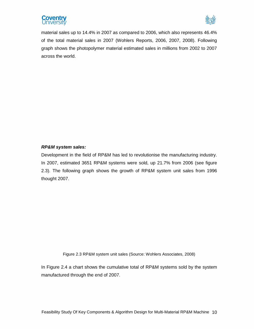
Software Model: In the pre-process stage a 3D model is designed in a CAD
environment and imported in STL or initial graphics exchange specification (IGES)
format into FDM workstation which uses Insight of Catalyst XP software to generate
Feasibility Study Of Key Components & Algorithm Design for Multi-Material RP&M Machine 18
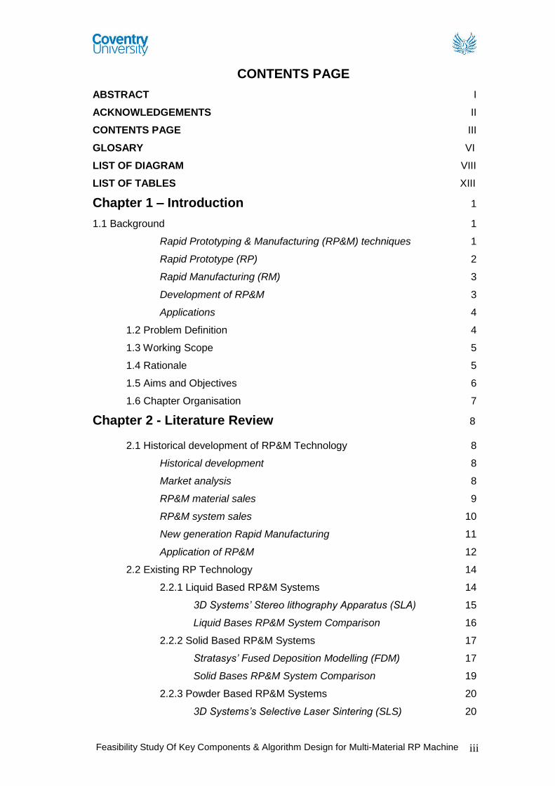
supports automatically. Some of the features of Catalyst software (see figure 2.8)
include:
It generates a precise deposition path that
guides the extrusion head to print model
layer by layer.
It automatically slices, orients and creates
any necessary support structures.
Figure 2.8 Catalyst XP
(virtualmdlab.eng.usf.edu, 2011)
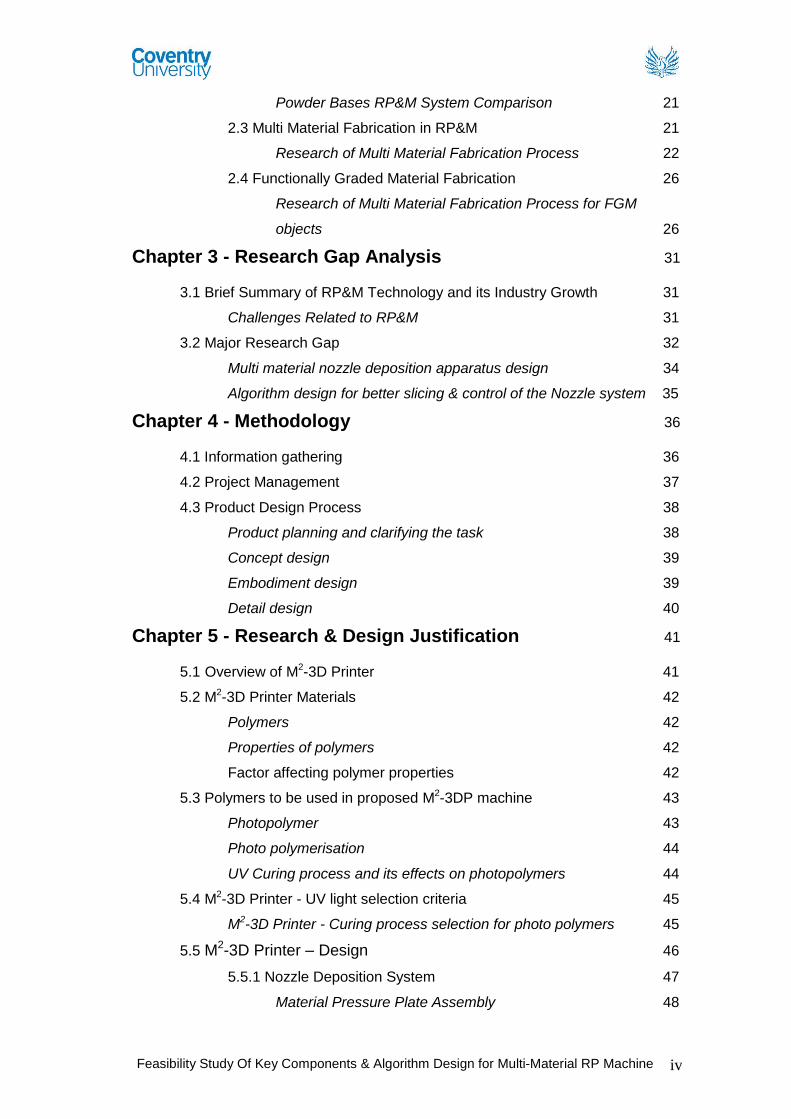
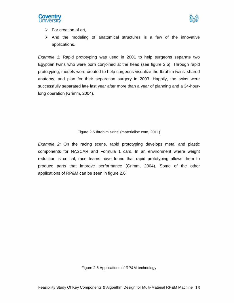
Process: In FDM process, two types of material are used in filament form, support
material and build material. Both materials are fed into a FDM liquefier head where
heating elements melt the material, which is then extruded deposited through the
nozzle in ultra thin layers, one layer at a time in a predetermined tool path generated
by the FDM Insight or Catalyst XP software. Material solidifies on cooling and the
process continues by moving the FDM head to create next layer (shown in figure 2.9).
Figure 2.9 FDM Process (xpress3d.com, 2011)
The parameters which affect the performance and functions of the FDM system are
(Chua, Leong& Lim, 2010):
Material column strength Material flexural modulus
Material viscosity Positioning accuracy
Road widths Deposition speed
Volumetric flow rate Tip diameter
Envelop temperature Part geometry
aa0682
Typewritten Text
These images have been removed
aa0682
Typewritten Text
Feasibility Study Of Key Components & Algorithm Design for Multi-Material RP&M Machine 19
Material: This process builds using wax, rigid plastic polymer, and elastomeric materials. Some of the materials available from fortus are shown in figure 2.10, 2.11 and 2.12.
Figure 2.10 ABSplus material
(fortus.com, 2011)
Figure 2.11 ABSi material
(fortus.com, 2011)
Figure 2.12 PPSF/PPSU
(polyphenylsufone) material (fortus.com, 2011)
Note: Please see appendix B for “Advantages, disadvantages and applications of FDM”.
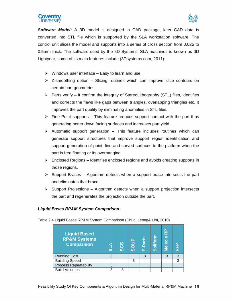
Solid Bases RP&M System Comparison: Table 2.5 Liquid Bases RP&M System Comparison (Source: Chua, Leong& Lim, 2010)
Solid Based RP&M Systems
Comparison
LO
M
FD
M
PL
T
MJ
M
So
lid
sc
ap
e
SS
M
ME
M
M-R
PM
LE
M
Off
set
Fab
be
rs
Low running cost 5
Building Time 5 2 5 2 5 2 3
Precision 5 5 5 2 2
Build volumes 5 2 2
Surface finishes 3
Type of Material Deposition S-M S-M S-M S-M S-M S-M S-M S-M S-M S-M
Range of available materials 5 2 2 5
Accuracy 1 2 2 2
Office friendly process 3 3 5 5
Minimal wastage 3 3 3 2
Adjustable Build layer 1 5 5
Requires support structures N N N N Y
Requires post processing Y
Requires post curing N N N
Requires Precise Power Adjustment Y Y Y Y
Fabrication of thin walls 1 2
Integrity of prototypes 1 2 1 1 5
Requires Removal of supports Y Y Y Y Y
Unpredictable shrinkage 1 1 1 1 Range (1Low – 5 High) Range increases from 1 low to 5 High
S-M = Single-Material Y = Yes, N = No
Note: Columns are left empty where no information is available from literature sources.
aa0682
Typewritten Text
These images have been removed
Feasibility Study Of Key Components & Algorithm Design for Multi-Material RP&M Machine 20
2.2.3 Powder Based RP&M Systems
Powder is by and large in the solid state but it is intentionally created as a category
outside the solid based RP&M systems to mean powder in grain like form. The RP&M
systems which fall into this category are shown in table 2.3, whereas, SLS technology
is explained below in detail.
Note: Please see appendix 2 for an overview of “3DP, DSPC and MJS systems”.
3D Systems’s Selective Laser Sintering (SLS):
SLS is a process that was patented in 1989. Its advantages over SLA revolve around
material properties. Many varying materials are possible and these materials can
approximate the properties of thermoplastics such as polycarbonate, nylon, or glass
filled nylon.
Software Model: A CAD data file is transferred into sinterstation systems in STL
format, where model is sliced and prepared for the SLS process to begin.
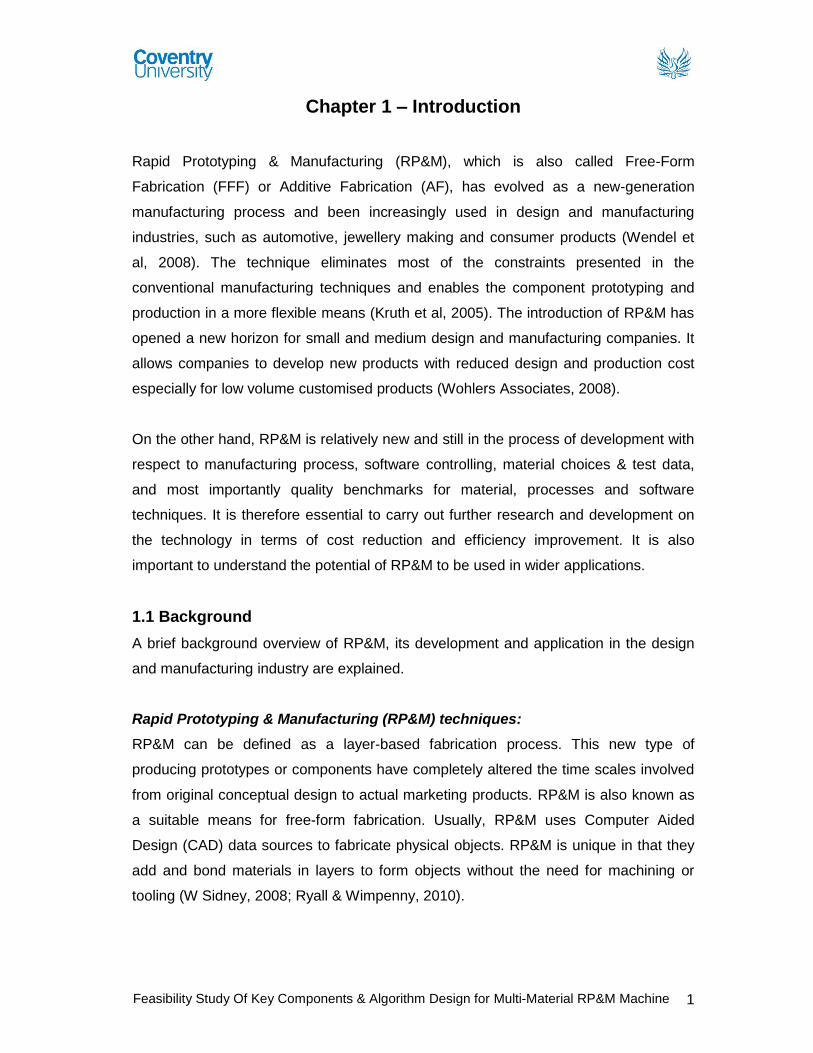
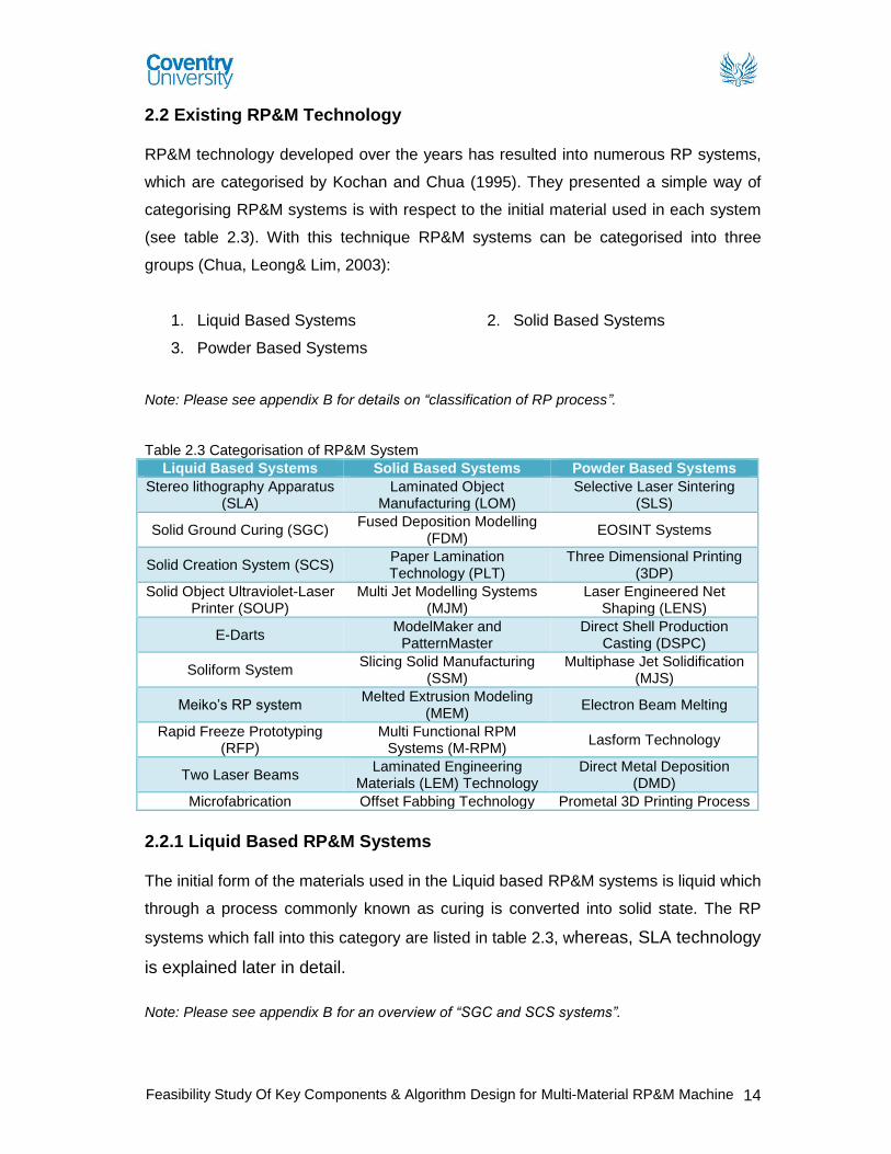
Process: Selective Laser Sintering (SLS) is a free-form fabrication technology
developed by the 3D Systems. It is a layered manufacturing method that creates solid,
3D objects by fusing powdered materials with a CO2 laser. A thin layer of powder
material is laid down and the laser “draws” on the layer, sintering together the particles
hit by the laser (Cindy Hartley, 2011). The layer is then lowered and a new layer of
powder is placed on top. This process is repeated one layer at a time until the part is
complete. Figure 2.13 below shows the system process chamber. The major
distinction between this and other rapid prototyping technologies is the wide variety of
materials that can be utilised. The functionality of materials allows SLS to cross over
into the direct digital manufacturing class (Todd Grimm, 2004).
Figure 2.13 SLS Process diagram (Milwaukee School of Engineering, 2010)
aa0682
Typewritten Text
This image has been removed
Feasibility Study Of Key Components & Algorithm Design for Multi-Material RP&M Machine 21
Material: The main types of materials used in SLS System are safe and non toxic,
easy to use, and can be easily stored, recycled and disposed off. These are as follows
(Chua, Leong& Lim, 2010):
Polyamide Nylon Metal
Ceramics Polycarbonate Thermoplastic elastomer
Note: Please see appendix B for details on “SLS materials”.
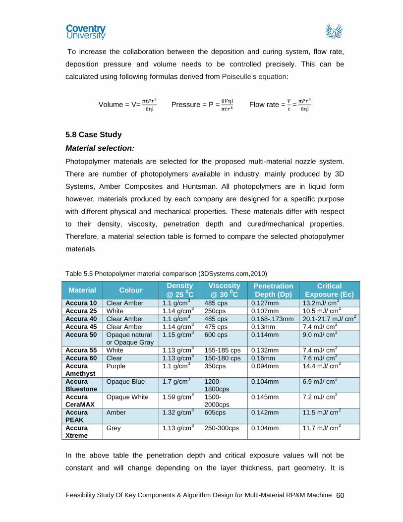
Feasibility Study Of Key Components & Algorithm Design for Multi-Material RP&M Machine 62
Curing Process selection:
For the time being the critical parameters (i.e. material flow rate per second, pressure
etc) for deposition are ignored but will be discussed later in fluid dynamics chapter.
With the help of the deposition apparatus four layers of material will be deposited on
top of each other one by one. Each material exhibits different properties of viscosity,
penetration depth and critical exposure limits. So the selected curing process will need
to be adjusted for each layer before the curing process can begin.
UV light curing process is selected for the selected materials. The UV light intensity will
be adjusted for each material. For the purpose of case study, the object is a simple
rectangular block as shown in figure 5.24. With the help of material deposition system
first layer of Accura 40 is deposited.
Figure 5.24 Accura 40 deposited material
Polymerisation Process:
UV light distance is adjusted, considering material thickness. The distance between
the UV light source and the material layer is less than 0.5mm. So the intensity of UV
light is above 98%.
𝐼𝑛𝑡𝑒𝑛𝑠𝑖𝑡𝑦 (mW
cm2) =
𝐸𝑛𝑒𝑟𝑔𝑦(mJ
cm2)
𝑇𝑖𝑚𝑒 (𝑠)
Energy required when layer thickness is 10µm is calculated by using the following
equation:
𝐿𝑎𝑦𝑒𝑟 𝑡ℎ𝑖𝑐𝑘𝑛𝑒𝑠𝑠 𝑜𝑓 𝑑𝑒𝑝𝑜𝑠𝑖𝑡𝑒𝑑 𝑚𝑎𝑡𝑒𝑟𝑖𝑎𝑙
𝐺𝑖𝑣𝑒𝑛 𝑃𝑒𝑛𝑒𝑡𝑟𝑎𝑡𝑖𝑜𝑛 𝑑𝑒𝑝𝑡ℎ 𝑜𝑓 𝑚𝑎𝑡𝑒𝑟𝑖𝑎𝑙=
𝑅𝑒𝑞𝑢𝑖𝑟𝑒𝑑 𝑒𝑛𝑒𝑟𝑔𝑦 𝑡𝑜 𝑐𝑢𝑟𝑒 𝑑𝑒𝑝𝑜𝑠𝑖𝑡𝑒𝑑 𝑚𝑎𝑡𝑟𝑒𝑖𝑎𝑙
𝐺𝑖𝑣𝑒𝑛 𝐸𝑛𝑒𝑟𝑔𝑦 𝑜𝑓 𝐶𝑟𝑖𝑡𝑖𝑐𝑎𝑙 𝑒𝑥𝑝𝑜𝑠𝑢𝑟𝑒
𝐿𝑑
𝑃𝑑=
𝑋
𝐸
10µm
127µm=
𝑋
13.2mJ/cm2
Required energy = 𝑋 = 1.04mJ/cm2
Height: 0.01mm Length: 10 mm Width: 0.01 mm
Feasibility Study Of Key Components & Algorithm Design for Multi-Material RP&M Machine 63
Table 5.8 Energy required for the selected materials
Material Penetration Depth (Dp) Critical Exposure Limit (Ec)
Accura 25 10µm 0.98 mJ/ cm2
Accura 40 10µm 1.23 mJ/ cm2
Accura 55 10µm 0.56 mJ/ cm2
Accura 60 10µm 0.48 mJ/ cm2
Accura Xtreme 10µm 1.13 mJ/ cm2
Fluid Dynamics:
Rate of flow of liquid through a capillary tube of radius “r” and length “l” can be
calculated by using equation 1 derived from Poiseulle’s law:
V= 𝜋𝑡𝑃𝑟4
8ηl =
∆𝑃
8ηl/𝜋𝑡𝑟4 = ∆𝑃
𝑅 Equation 1
P = Pressure difference ∆𝑃
R = Fluid resistance (R =8ηl/𝜋𝑟4)
Rate of flow per second is calculated by changing equation 1.
V= 𝜋∆𝑃𝑡𝑟4
8ηl Equation 2
Table 5.9 Equation Symbols
Symbols Units
Volume V m3(Meter)
Pi 𝜋
Pressure P Pa (Pascal)
Time T S (Second)
Viscosity Η ps (Poise second)
Length L m (Meter)
Radius R m (Meter)
As the fluid or material is going from applied pressure to atmospheric pressure,
therefore, we can ignore the pressure change. So
∆𝑃 = 𝑃
So equation 2 is rearranged to calculate the pressure required to deposit a certain
amount of volume per second.
Volume = V = 𝜋𝑃𝑡𝑟4
8ηl Equation 2
Pressure = P = 8𝑉ηl
𝜋𝑡𝑟4 Equation 3
Feasibility Study Of Key Components & Algorithm Design for Multi-Material RP&M Machine 64
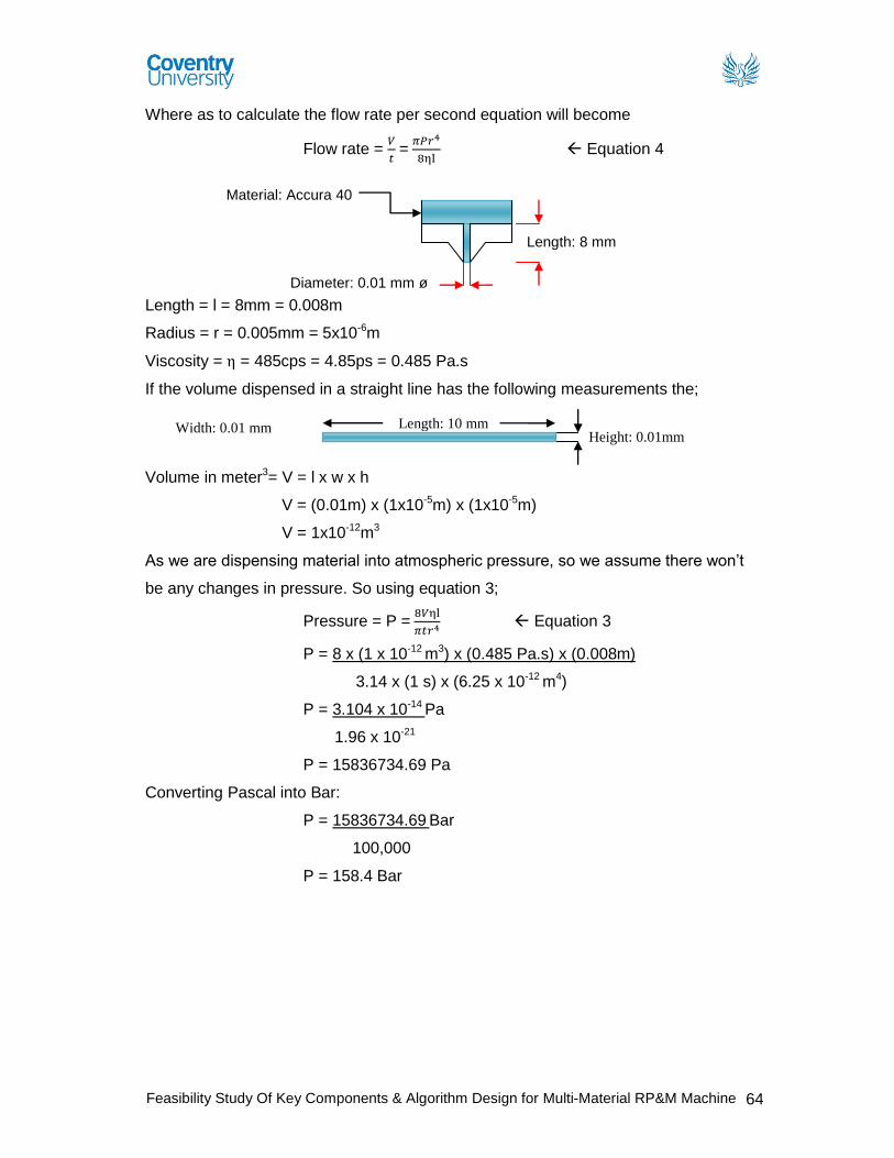
Where as to calculate the flow rate per second equation will become
Flow rate = 𝑉
𝑡 =
𝜋𝑃𝑟4
8ηl Equation 4
Length = l = 8mm = 0.008m
Radius = r = 0.005mm = 5x10⁻⁶m
Viscosity = η = 485cps = 4.85ps = 0.485 Pa.s
If the volume dispensed in a straight line has the following measurements the;
Volume in meter3= V = l x w x h
V = (0.01m) x (1x10⁻⁵m) x (1x10⁻⁵m)
V = 1x10-12m3
As we are dispensing material into atmospheric pressure, so we assume there won’t
be any changes in pressure. So using equation 3;
Pressure = P = 8𝑉ηl
𝜋𝑡𝑟4 Equation 3
P = 8 x (1 x 10-12 m3) x (0.485 Pa.s) x (0.008m)
3.14 x (1 s) x (6.25 x 10⁻¹² m4)
P = 3.104 x 10⁻¹⁴ Pa
1.96 x 10⁻²¹
P = 15836734.69 Pa
Converting Pascal into Bar:
P = 15836734.69 Bar
100,000
P = 158.4 Bar
Material: Accura 40
Length: 8 mm
Diameter: 0.01 mm ø
Height: 0.01mm Length: 10 mm Width: 0.01 mm
Feasibility Study Of Key Components & Algorithm Design for Multi-Material RP&M Machine 65
Chapter 6 – Software Development of M2-3D Printer In this chapter, some algorithms will be developed to support the design of M2-3D
Printer for multi-material RP&M processing. It gives an introduction about STL format
file and NURBS curve. A NURBS-based slicing algorithm is developed to represent the
boundary contours of the sliced layer in RP&M technology to maintain the geometrical
accuracy of original CAD model. In addition, a nozzle change algorithm for fabrication
of two-material object in RP&M technology is also developed in this chapter. The
developed software can be used to reduce the build time of fabrication and guide the
fabrication process of two material objects in the designed M2-3D Printer.
6.1 STL Format File and its Problems
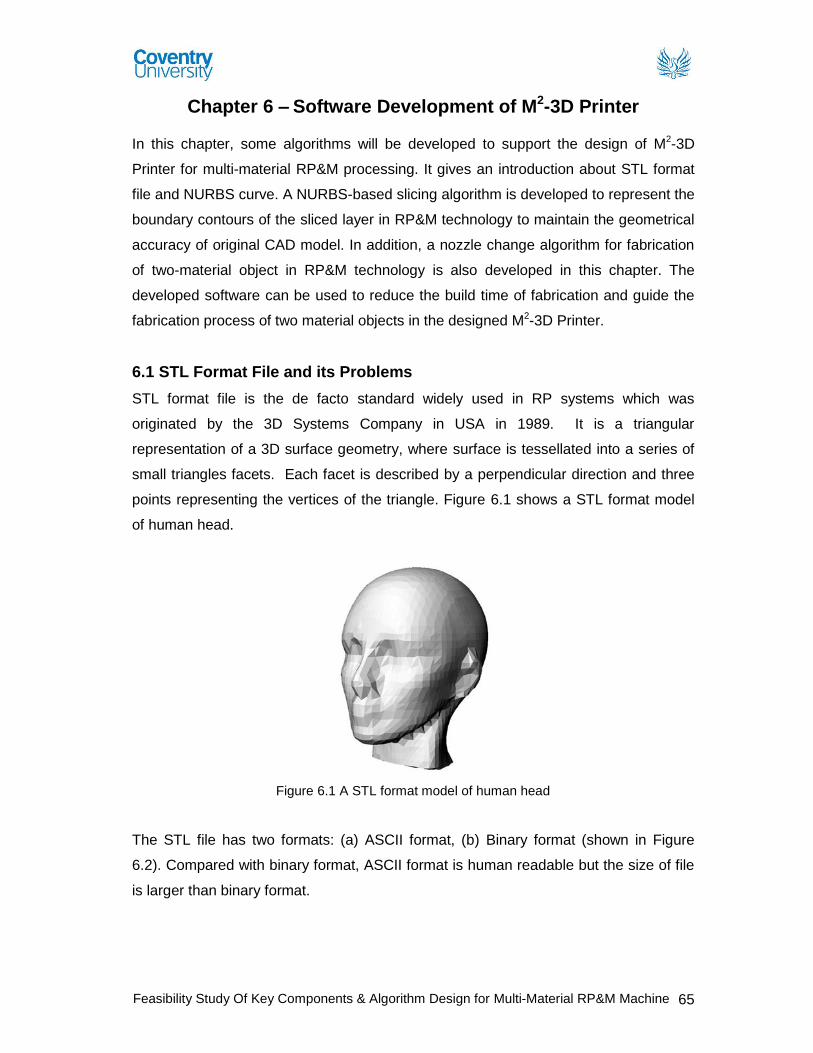
STL format file is the de facto standard widely used in RP systems which was
originated by the 3D Systems Company in USA in 1989. It is a triangular
representation of a 3D surface geometry, where surface is tessellated into a series of
small triangles facets. Each facet is described by a perpendicular direction and three
points representing the vertices of the triangle. Figure 6.1 shows a STL format model
of human head.
Figure 6.1 A STL format model of human head
The STL file has two formats: (a) ASCII format, (b) Binary format (shown in Figure
6.2). Compared with binary format, ASCII format is human readable but the size of file
is larger than binary format.
Feasibility Study Of Key Components & Algorithm Design for Multi-Material RP&M Machine 66
(a) ASCII format solid name facet normal ni nj nk outer loop vertex v1x v1y v1z vertex v2x v2y v2z vertex v3x v3y v3z endloop endfacet … endsolid name
Figure 6.2 The two formats of STL file
STL file provides a simple method to represent the 3D CAD model and has been used
by most single material RP&M systems in recent years. However, there are many
types of errors in STL files such as holes, missing, gaps, overlapping and degenerate
facets, etc. In addition, STL is inherent inaccuracy in terms of geometrical
representation and it does not contain topological data, so it is difficult to represent
accurate CAD models and hard to be used to represent the multi-material object in
RP&M technology (Chua, Leong& Lim, 2010). So, there is a need to develop a method
to support multi-material fabrication in RP&M technology.
6.2 NURBS Curve
NURBS are mathematical representations of 3D geometry that can accurately
describe any shape from a simple 2D line, circle, arc, or curve to the most complex 3D
organic free-form surface or solid. Figure 6.3 shows a NURBS curve with 8 control
points. A NURBS curve is defined by its order, a set of weighted control points, and a
knot vector:
(1) The control points determine the shape of the curve.
(2) The knot vector is a sequence of parameter values that determines where and how
the control points affect the NURBS curve.
(3) The order of a NURBS curve defines the number of nearby control points that
influence any given point on the curve.
(b) Binary format UINT8[80] – Header UINT32 – Number of triangles foreach triangle REAL32[3] – Normal vector REAL32[3] – Vertex 1 REAL32[3] – Vertex 2 REAL32[3] – Vertex 3 UINT16 – Attribute byte count end
Feasibility Study Of Key Components & Algorithm Design for Multi-Material RP&M Machine 67
Figure 6.3 A NURBS curve with 8 control points
Compared with STL format file, NURBS – based curves have some advantages
(showed in Table 6.1):
Table 6.1 The comparison between STL file and NURBS
STL NURBS Large storage space Small storage space
Inherently inaccurate Accurate
Hard to represent multi-material model Can be used to represent multi-material model
Simple Complex
As STL does not contain topological data and only a facet model derived from precise
CAD models. It needs several times large storage space for a complex accuracy CAD
model compared with NURBS. Meanwhile, STL file is inherently inaccurate as it is an
approximate model, but NURBS is a mathematical model which offers great precision
for freeform shape model. In addition, STL file is quite hard to represent multi-material
model, but NURBS can be used to represent multi-material model easy. However,
compared with STL file, NURBS is much more complex.
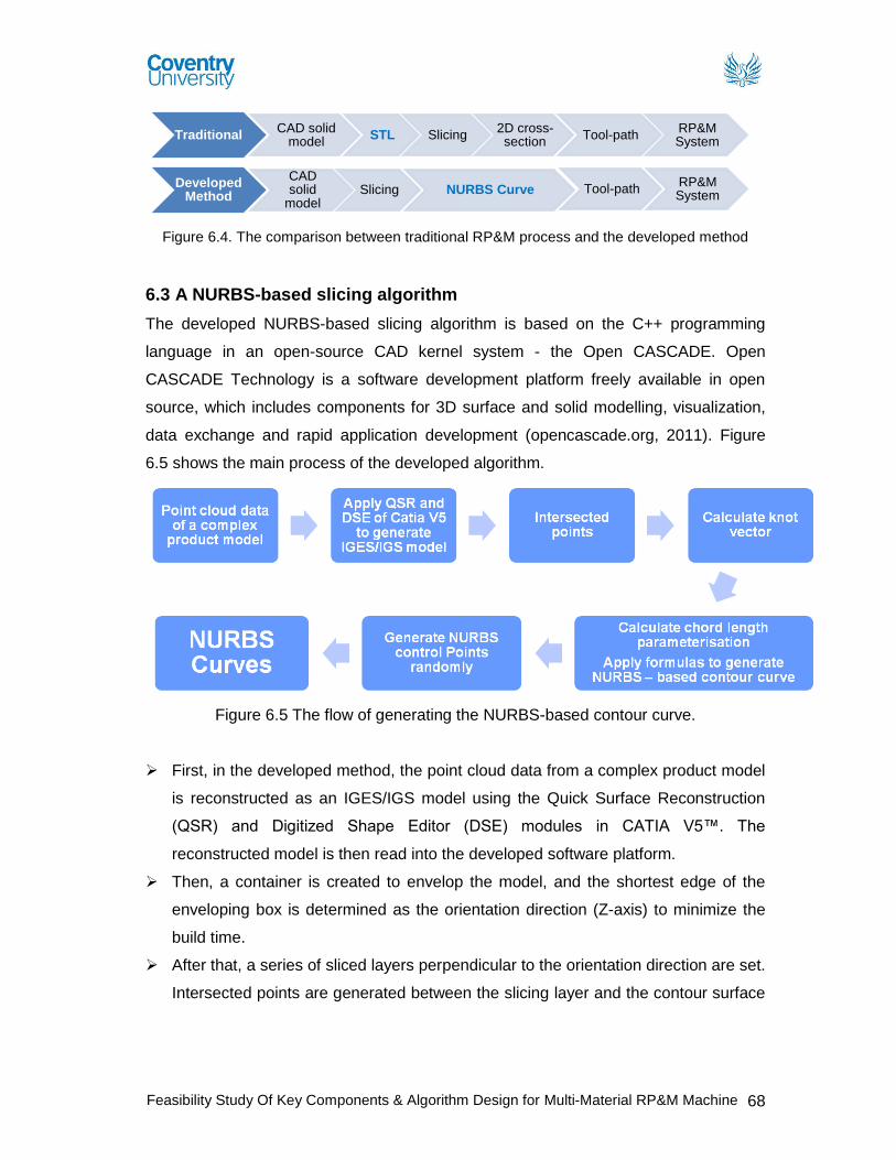
In this thesis, a method to use NURBS curve instead of STL format file to support
multi-material RP technology is developed. Figure 6.4 shows the comparison between
traditional RP process and the developed method. In the traditional method, it slices a
STL model which transform from the original CAD model to get a 2D cross-section.
This can be used to generate tool-path for the RP&M systems. In the developed
method, it directly sliced the CAD model instead of the STL file conversion and
NURBS (Non-Uniform Rational B-Spline)-based curve are introduced to represent the
boundary contours of the sliced layers in RP&M to maintain the geometrical accuracy
of original CAD model and to support the multi-material RP&M technology.
Feasibility Study Of Key Components & Algorithm Design for Multi-Material RP&M Machine 68
Figure 6.4. The comparison between traditional RP&M process and the developed method
6.3 A NURBS-based slicing algorithm
The developed NURBS-based slicing algorithm is based on the C++ programming
language in an open-source CAD kernel system - the Open CASCADE. Open
CASCADE Technology is a software development platform freely available in open
source, which includes components for 3D surface and solid modelling, visualization,
data exchange and rapid application development (opencascade.org, 2011). Figure
6.5 shows the main process of the developed algorithm.
Figure 6.5 The flow of generating the NURBS-based contour curve.
First, in the developed method, the point cloud data from a complex product model
is reconstructed as an IGES/IGS model using the Quick Surface Reconstruction
(QSR) and Digitized Shape Editor (DSE) modules in CATIA V5™. The
reconstructed model is then read into the developed software platform.
Then, a container is created to envelop the model, and the shortest edge of the
enveloping box is determined as the orientation direction (Z-axis) to minimize the
build time.
After that, a series of sliced layers perpendicular to the orientation direction are set.
Intersected points are generated between the slicing layer and the contour surface
Traditional CAD solid
model STL Slicing
2D cross-section
Tool-path RP&M System
Developed Method
CAD solid
model Slicing NURBS Curve Tool-path
RP&M System
Feasibility Study Of Key Components & Algorithm Design for Multi-Material RP&M Machine 69
of the model. The knot vector and control points are calculated based on the
obtained intersected points.
Finally, in order to establish a NURBS-based contour curve on the boundary
between the sliced layer and the model (Ci,1), formulas (1) and (2) are applied to
generate NURBS-based contour curve (Piegl, et al., 1997).
Ci,j(u) = ∑ wiNi,p(u)C_Pi,jn
i=0 (1)
Ni,0(u) = {1 0
ui≤ u ≤ ui+1otherwise
, and Ni,p(u) = u−ui
ui+p−uiNi,p−1(u) +
ui+p+1−u
ui+p+1−ui+1Ni+1,p−1(u) (2)
Where Ci,j represents the jth contour curve in the ith RP layer; u is the parametric
variable ( ]1,0[u ); iw is the weight associated with control points; jiPC ,_ is the control
point; p is degree. Table 6.2 shows the detailed steps of the developed NURBS-based
slicing algorithm.
Table 6.2. The steps of slicing algorithm
Steps START
1. Read a CAD model (IGS/IGES format)
2. Make a container to accommodate the CAD model
3. Determine the direction of slicing (the longest segment of the CAD model), and set it to be Z-axis
4. Along the Z-axis, slice the model with a uniform thickness, and get all the layers
( 𝑳𝟎 , 𝑳𝟏 , … 𝑳𝒏 ) of the model
5. Get the contour segments of the first layer ( 𝑳𝟎 )
6. Explorer all the segments of the ( 𝑳𝟎 ) to get the number of the segments ( 𝑵𝒎 )
7. Select a segment randomly as the start segment ( 𝑺𝟎 ) and find the start point ( 𝑷𝟎,𝒔 )
and the end point ( 𝑷𝟎,𝒆 ) of ( 𝑺𝟎 )
8. Explorer all the segments ( 𝑺𝒋 ) except the selected one and find a segment with start
point ( 𝑷𝟏,𝒔 ) equals to ( 𝑷𝟎,𝒆 ). Named it as the second segment ( 𝑺𝟏 ) (𝑗 = 0,1,2, … 𝑚)
9. Loop this process of step 8 until all segments along the sequence from start to end of the layer ( 𝑳𝟎 ) are found
10. Join all the segments of the ( 𝑳𝟎 ) to generate a closed NURBS curve (𝑪𝟎,𝟎)
11. Loop the process from step 5 to step 10 to obtain all closed NURBS curves (𝑪𝒊,𝟎) for
the CAD model (𝑖 = 0,1,2, … 𝑛)
END
Feasibility Study Of Key Components & Algorithm Design for Multi-Material RP&M Machine 70
An example to illustrate the developed slicing algorithm:
A tibia model of human right leg is used to illustrate the developed slicing algorithm.
The length, width, height and volume of the tibia model are 405.29mm, 106.96mm,
98.249mm and 471600mm3 respectively. The process for the NURBS-based contour
curve generation is shown in Figure 6.6.
6.4 A Nozzle Change Algorithm for Two-material Object
The normal manufacturing processing for the fabrication of two-material object with
RP&M machines are shown in Figure 6.7. It uses additive manufacturing method from
bottom to top layer by layer to complete the object. For example, in Figure 6.7(c),
firstly, it fabricates material A by nozzle 1 along the tool-path, then nozzle is changed
from 1 to nozzle 2 and its positioned in the right location for the fabrication of material
B. After the layer is finished, nozzle is changed to nozzle 1 to fabricate the material A
on the next layer In Figure 6.7(b), and then its changed back to nozzle 2 to fabricate
material B, layer by layer until the fabrication of an object is completed.
When the object is composed by different materials, the RP&M machine have to
change the different nozzles to fabricate different materials in every layer. This slows
the fabrication process due to the time required for nozzle change and its positioning
at the right location. This also decreases the surface quality because the fabrication
(a) An tibia model for RP tool-path generation
(b) An enveloping box for the model and a sliced layer
(c) The cross-section segments (d) A NURBS-based contour curve generated by the slicing algorithm
Figure 6.6 An example to illustrate the developed slicing algorithm.
Feasibility Study Of Key Components & Algorithm Design for Multi-Material RP&M Machine 71
processing has too many start and end points, which will increase staircase problem
and will cause warpage of the fabrication object (Kou and Tan, 2009). In this project, a
nozzle sequence algorithm is developed based on the C++ programming language
and the Open CASCADE software develop platform. It can be used to control the
above designed M2 – 3DP RP&M machine to fabricate the two-material object with the
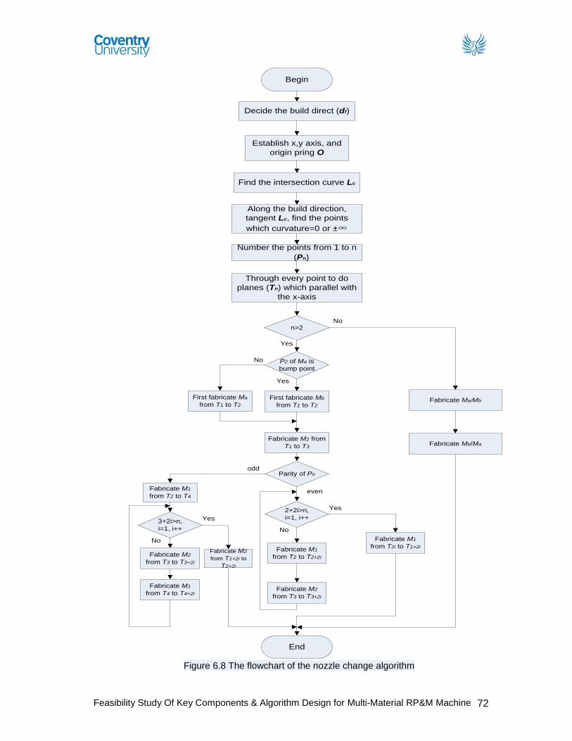
least changeover of the nozzles. Figure 6.8 shows the flowchart of the nozzle change
algorithm.
Figure 6.7 The processing for the two-material objects fabrication in RP&M
Material A
Material A
Material B
Material B
Tool-paths
Feasibility Study Of Key Components & Algorithm Design for Multi-Material RP&M Machine 72
Begin
Decide the build direct (df)
Establish x,y axis, and
origin pring O
Find the intersection curve Lc
Along the build direction,
tangent Lc, find the points
which curvature=0 or ±∞
Number the points from 1 to n
(Pn)
Through every point to do
planes (Tn) which parallel with
the x-axis
n>2
Yes
No
Fabricate Ma/Mb
Fabricate Mb/Ma
End
P2 of Ma is
bump point
First fabricate Ma
from T1 to T2
First fabricate Mb
from T1 to T2
Fabricate M2 from
T1 to T3
Parity of Pn
Yes
No
2+2i>n,
i=1, i++
even
odd
Yes
Fabricate M1
from T2i to T1+2i
No
Fabricate M1
from T2 to T2+2i
Fabricate M2
from T3 to T3+2i
3+2i>n,
i=1, i++
Yes
Fabricate M2
from T1+2i to
T2+2i
No
Fabricate M2
from T3 to T3+2i
Fabricate M1
from T4 to T4+2i
Fabricate M1
from T2 to T4
Figure 6.8 The flowchart of the nozzle change algorithm
Feasibility Study Of Key Components & Algorithm Design for Multi-Material RP&M Machine 73
Compared with the traditional method:
The ball showed in Figure 6.9 with two different materials is used in this comparison.
The diameter of the ball is 20cm. The thickness of every layer for RP&M system is
0.2mm. So the ball has 1000 layers totally.
(a) An ball model with two different materials
(b) The two parts of the ball
(c) Slicing the ball for one layer (d) Contour of the layer
(e) Tool-paths generated for the material A (f) Tool-path generated for the material B
Figure 6.9 An example to illustrate the nozzle change algorithm.
Material A
Material B
Feasibility Study Of Key Components & Algorithm Design for Multi-Material RP&M Machine 74
The format to calculate the totally build time is given as follows:
Tt = Tc + Tp + Tf (3)
Where Tc is the total time spent to change different nozzle, Tp is the total time spent for
nozzle positioning, and Tf is the total time spent for fabrication. They can be calculated
using following equations:
Tc = Nc × tc; Tp = Np × tp; Tf = Nf × tf; (4)
Where Nc is the times of the nozzle change, Np is the times of the nozzle positioning,
and Nf is the times of the nozzle fabrication; tc is the time spend to change a nozzle, tp
is the time spend to position a nozzle, and tf is the time spend to fabricate one material
part of the layer.
We assumed that tc = 60 seconds, tp = 45 seconds, tf = 30 seconds. Figure 6.10
shows the fabrication processing for the ball in the developed nozzle change
algorithm. The Table 6.3 shows the build time comparison between traditional
processing and the developed change nozzle algorithm.
Figure 6.10 The fabrication processing for the ball in the nozzle change algorithm
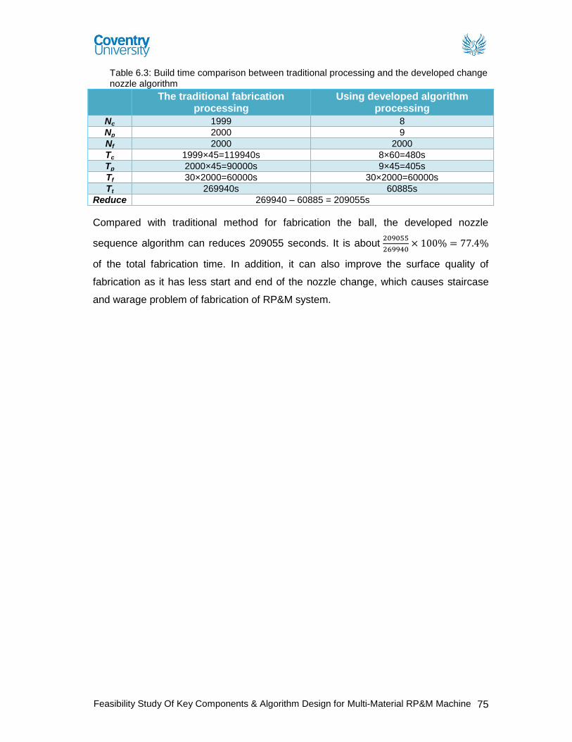
Feasibility Study Of Key Components & Algorithm Design for Multi-Material RP&M Machine 75
Table 6.3: Build time comparison between traditional processing and the developed change nozzle algorithm
The traditional fabrication processing
Using developed algorithm processing
Nc 1999 8
Np 2000 9
Nf 2000 2000
Tc 1999×45=119940s 8×60=480s
Tp 2000×45=90000s 9×45=405s
Tf 30×2000=60000s 30×2000=60000s
Tt 269940s 60885s
Reduce 269940 – 60885 = 209055s
Compared with traditional method for fabrication the ball, the developed nozzle
sequence algorithm can reduces 209055 seconds. It is about 209055
269940× 100% = 77.4%
of the total fabrication time. In addition, it can also improve the surface quality of
fabrication as it has less start and end of the nozzle change, which causes staircase
and warage problem of fabrication of RP&M system.
Feasibility Study Of Key Components & Algorithm Design for Multi-Material RP&M Machine 76
Conclusion The major focus of the dissertation is on the feasibility study of developing a unique
multi-material nozzle deposition system which is flexible, accurate and can handle up
to seven materials with controllable deposition. By evaluating all the findings with
respect to the design of a multi-material nozzle deposition apparatus, its suitability to
handle more than two materials, slicing and controlling algorithms, it is concluded that
the selected proposed multi-material nozzle deposition system design is feasible for
multi-material deposition of more than two materials and can be further developed to
be used in the proposed M2-3D Printer system. Comparison of existing multi material
deposition system research with the proposed feasibility model of M2-3D Printer is
presented in table 7.1 (see page 79). Developed multi-material slicing and its nozzle
control algorithm will reduce the processing time, data storage space and overall
improve the quality of fabricated objects in the proposed M2-3D Printer system. With
the reference to the aims and objectives set out at the start of the project are
completed at the end of the dissertation. The objectives included:
To analyse and evaluate existing commercially available RP&M systems:
RP&M systems research has been carried out mainly with the help of research
papers, articles, reports and company websites. The literature review and its
analysis conclude that applications of the most RP&M systems are either
limited by the material choice and its properties or by its fabrication process
itself.
To analyse and evaluate existing research on multi-material RP&M
systems: Present research on multi-material RP&M systems has been carried
out mainly with the help of research papers, articles, and published reports.
The literature review and its analysis conclude that the current research being
done in this field has been focused on developing a multi-material deposition
apparatus which can be used to deposit up to two materials or to deposit FGM
materials. Most of the RP&M systems presented need further development to
improve the process quality, control and repeatability.
To analyse and evaluate the need of multi-material RP&M system with
respect to related industries: The literature review and its analysis of the
Feasibility Study Of Key Components & Algorithm Design for Multi-Material RP&M Machine 77
technologies, industrial trends, and research and development of RP&M shows
that there is a growing interest from number of industries in multi-material
RP&M system. There is a demand of more capable RP&M systems which can
fabricate functional models from different materials. It will reduce the
manufacturing cost and open doors for more complex, low volume product
design and production.
To review and analyse existing deposition apparatus design: Research
analysis of the commercial market and the current research being done has
clearly suggested that there is a need of Multi material RP&M system. It is
concluded that commercial market of RP&M has no feasible solution available
for multi material fabrication, whereas, recent research has gained some
progress in the field of multi material fabrication of components from two
materials but there is no deposition apparatus designed to deposit more than
two materials.
To produce a research gap analysis: Literature review is critically analysed
to develop an understanding of issues related to the current RP&M technology,
its industry trend and current research and development. The analysis are
made and concluded to establish the current research gaps and topic of
proposed research (See chapter 3 for details).
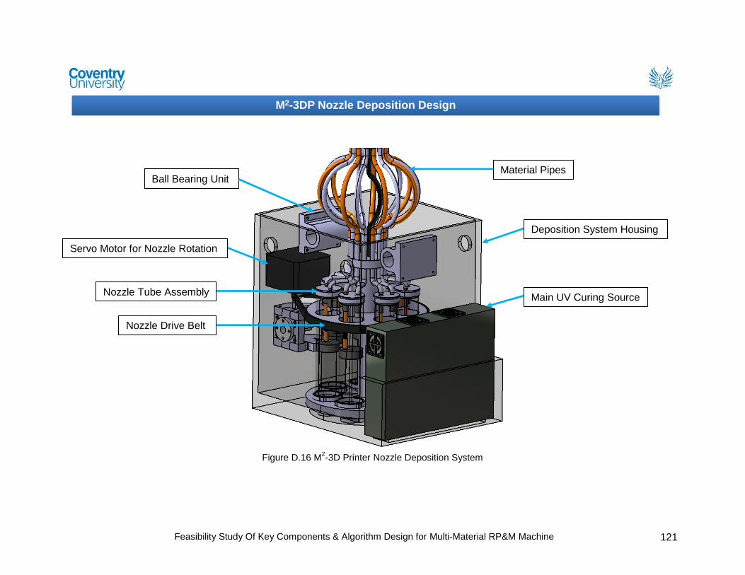
To produce design specifications for the key components of the
proposed multi-material RP&M machine: The proposed M2-3D Printer
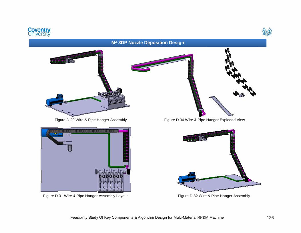
system, consists of four major components, feeding apparatus, material
delivery and flow system, deposition apparatus and build platform. All the
components are designed to work with photopolymers materials. The key
specifications of material disposition system are set by understanding the
photopolymer materials.
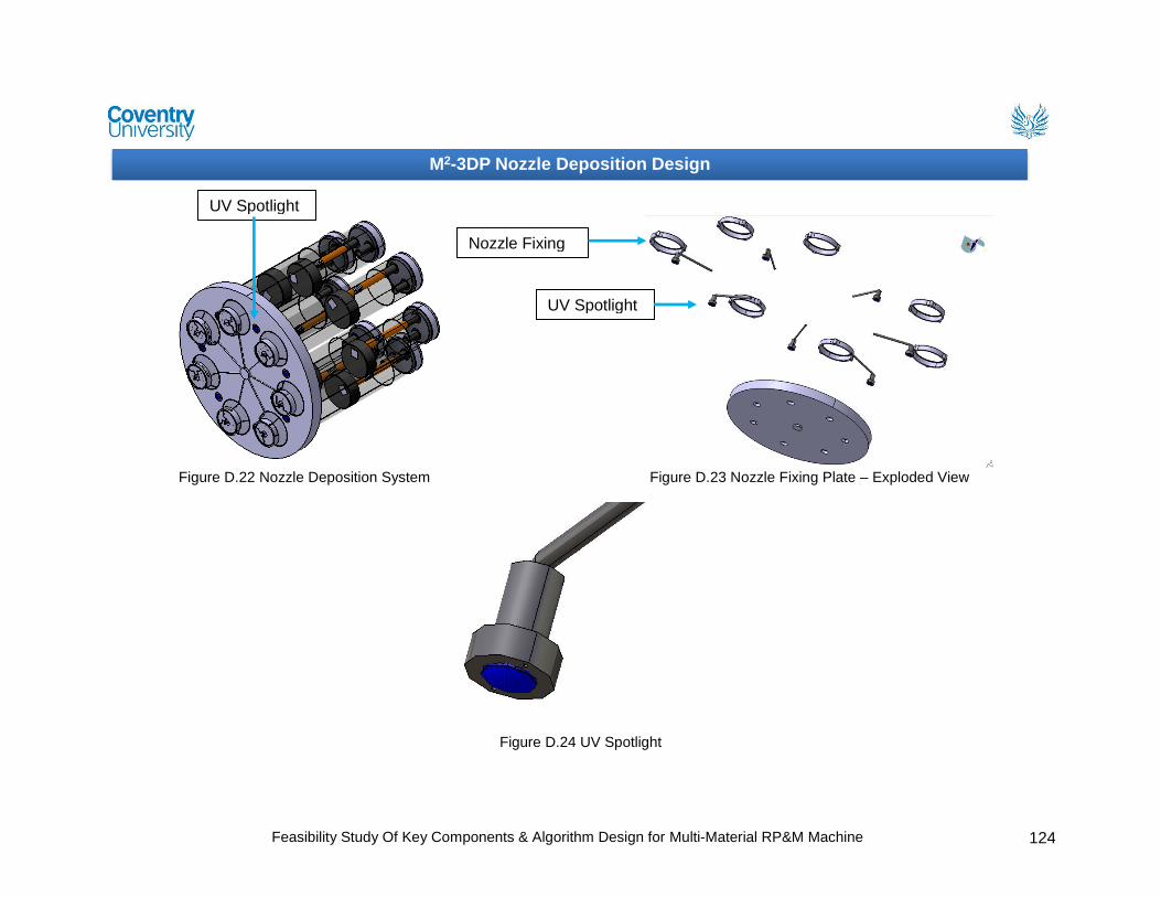
To design a nozzle of “M2-3D Printer” for a controlled and accurate
deposition: Nozzle design of deposition apparatus can build objects with a
lower resolution of 10µm. It comes with a unique deposition controller which is
operated by an electro magnet for controlled and accurate deposition.
Feasibility Study Of Key Components & Algorithm Design for Multi-Material RP&M Machine 78
Multi material nozzle deposition apparatus design: A concept model of
multi-material deposition apparatus is designed which can deposit more than
two build materials. Photopolymer is the material choice which can be
deposited in a continuous or drop format from the design apparatus. Flow rate
and volume can be controlled by using the presented formulas for accurate
deposition and to minimise the over/under fill issues. Deposited material can be
fabricated by two UV curing options (Major cure or spot curing). The right
choice of UV curing source and its set parameters affect directly the quality of
fabrication. Formula is used to set UV parameters to gain more control and to
improve its curing quality (See chapter 5 & appendix D for design details).
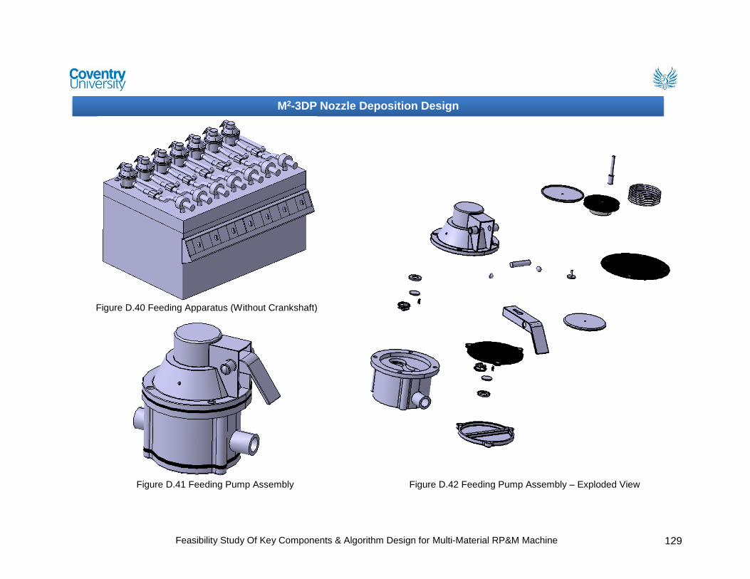
To conduct detailed design of feeding apparatus for the proposed M2-3D
Printer: Feeding apparatus design comes with seven tanks for different
materials. Material is feed to the Nozzle apparatus by pumping the material
from the tanks, through flow pipes. Off the shelf pressure control valves are
used to control the pressure in the flow pipes See chapter 5 & appendix D for
design details).
Algorithm design for better slicing and control of the Nozzle system: A
detailed literature review of the available RP&M system, its processes and
software has identified many problems such as accuracy, quality and process
repeatability. It is concluded that STL file format is designed to represent one
material type CAD models, comes with inherent issues of inaccuracy with
respect to dimensional representation and requires large storage space for
complex CAD model representation. Therefore a NURBS based slicing
algorithm is developed for multi-material representation of CAD model to
improve the quality of the RP&M components in terms of better geometrical
representation of multi material objects. Developed NURBS-based slicing
algorithm can maintain the geometrical accuracy of original CAD model and to
support multi-material RP technology. In addition, a nozzle change algorithm
was also developed to reduce the build time of fabrication and to support the
design of M2-3D Printer.
Feasibility Study Of Key Components & Algorithm Design for Multi-Material RP&M Machine 79
Table 7.1 Multi Material RP&M Technology Comparison with proposed feasibility model of M2-
3D Printer
Multi Material RP&M Technology Comparison
Mo
re t
han
Tw
o M
ate
rial
Dep
osit
ion
Tw
o M
ate
rial D
ep
osit
ion
FG
M D
ep
osit
ion
Un
der-
fill P
rob
lem
Over-
fill
Pro
ble
m
Pri
nt
Qu
ali
ty
Nu
mb
er
of
No
zzle
s
Mate
rial C
ho
ice
Jafari and Han et al (2000) FDMC system
N Y N 3 3 Four 2
Yang and Evans (2004) FGM powder deposition apparatus
N N Y 3 2 One
Khalil and Sun’s (2005) Multi-material FDM system
N Y N 3 3 Four 2
Weiss and Amon (2005) fibrin based scaffolds RP system
N Y N Four 2
Liew et al (2001 & 2002) dual material fabrication method
N Y N 2
Ram et al (2007) UC processing method N Y N 2 Beal et al (2004) X graded powder deposition system
N N Y 1
Mazumder et al. (2003) FGM fabrication method
N N Y 1
Chiu and Yu (2008) direct digital manufacturing methodology
N N Y 1 2
Morvan et al (2001) heterogeneous flywheel fabrication by LENS
N N Y 1
Kieback et al (2003) FGM fabrication on powder based 3DP system
N N Y 1
Kieback et al (2003) FGM fabrication on SLS system
N N Y 1
Kieback et al (2003) FGM fabrication on FDM system
N N Y 1
Kieback et al (2003) FGM fabrication on SLA system
N N Y 1
Syed I (2011) Feasibility Design of M2-
3D Printer Y Y N 1* 1* 4* Seven 4
Range (1Low – 5 High) Range increases from 1 low to 5 High S-M = Single-Material Y = Yes, N = No * = Needs to be tested physically.
Note: Columns are left empty where no information is available from literature sources.
Future work and recommendations:
The further work should be carried out in future research and development of the
presented concept of multi-material nozzle deposition system to support a fully
Feasibility Study Of Key Components & Algorithm Design for Multi-Material RP&M Machine 80
functional multi-material 3D printer (“M2-3D Printer”). Presented research can be used
as a feasibility study for the proposed M2-3D Printer system so more research needs to
be carried out in implementation of this concept design into a working prototype model.
More research should be carried out in developing algorithms for the multi-nozzle
control and positioning for accurate and precious deposition.
The research areas which need further research and development are:
First prototype needs to be manufactured for the physical testing of multi-
material nozzle deposition system which can fabricate objects with more than
two materials.
Further develop an algorithm for the better control of multiple nozzle system
which can help improve the fabrication quality and process time.
A better statistical quality and control data needs to be developed with respect
to the current RP&M systems which can be used as a benchmark for the
manufacturing industry.
A wide range of materials need to be developed which can be used as an
alternative to the materials used in conventional manufacturing.
A better statistical data with respect to testing and quality needs to be
developed for the available variety of RP&M materials which can be used as a
benchmark for the manufacturing industry.
Feasibility Study Of Key Components & Algorithm Design for Multi-Material RP&M Machine 81
References
_connect (2010) RIM polyurethane MG 453, automotive grill [online] available from <https://ktn.innovateuk.org/web/polymers/articles/-/blogs/ebalta-maintain-the-lowest-viscosity-rim-and-vacuum-casting-materials-for-the-rapid-prototyping-market?ns_33_redirect> [01st September 2011]
3D Systems (2010) ProJet™ 6000 Professional 3D Printer [online] available from <http://printin3d.com/projet-6000> [01st September 2011] 3D Systems (2010) 3D Systems Success Story [online] available from <www.3dsystems.com/products/datafiles/success_stories/Tushino_SLA_XL_CS.pdf> [01st September 2011] Anderson, S. (2009) Pushing rapid prototyping materials to the limit [online] available from <http://www.mmsonline.com/articles/pushing-rapid-prototyping-materials-to-the-limit> [01st September 2011] ALEX DEN OUDEN (2004) Fused deposition modelling [online] available from <http://www.alexdenouden.nl/08/rapprod7.htm> [01st September 2011]
Agentdraw (2010) Prototype [online] available from <http://www.agentdraw.co.uk/prototype.php> [01st September 2011] Anvil Prototype (2009) Digital Design and Manufacturing [online] available from <http://www.anvilprototype.com/StayUpdated/tabid/67/NewsID/29/Default.aspx> [01st September 2011] A. R. Lindberg. (1990) Processes and materials of manufacturing (Fourth edition). Beal, V.E., Erasenthiran, P., Hopkinson, N., Dickens, P. and Ahrens, C.H. (2004) ‘Fabrication of x-graded H13 and Cu powder mix using high power pulsed Nd: YAG laser’. Solid Freeform Fabrication Symposium, Texas 187-197 Chua, C. K., Leong, K. F. & Lim, C. S. (2010) Rapid Prototyping: Applications and Applications (Third Edition). Singapore: World Scientific Chua, C. K., Leong, K. F. & Lim, C. S. (2003) Rapid Prototyping: Applications and Applications (Second Edition). Singapore: World Scientific Cornelius, T. and Leondes. (2003) Computer Aided and Integrated Manufacturing Systems. Singapore: World Scientific Cadem, A.S., (2008) Fused deposition modeling [online] available from <www.additive3d.com/faq/faq220.htm> [01st September 2011] Cubic Technologies (2007) Laminated Object Manufacturing [online] available from <www.cubictechnologies.com/Helisys.htm> [01st September 2011]
Feasibility Study Of Key Components & Algorithm Design for Multi-Material RP&M Machine 82
Chiu, W.K. and Yu, K.M. (2008) ‘Direct digital manufacturing of three-dimensional functionally graded material objects’. Computer-Aided Design 40 (12): 1080-1093 Chartoff, R., McMorrow, B. and Lucas. P. (2003) ‘Functionally graded polymer matrix nano-composites by solid freeform fabrication: apreliminary report’. Proceedings of the 14th SFF symposium, Austin, TX 385-391 Design & manufacturing Laboratory (2009) Reverse Engineering Techniques in Bioengineering [online] available from <http://dml.chania.teicrete.gr/ereuna/3dmedical1_en.html> [01st September 2011] Doi, M. (1996) Introduction to Polymer Physics. Oxford: Oxford university press D-MEC (2005) STL file editing software [online] available from <www.d-mec.co.jp/eng/products/scs/lineup/soft.html> [01st September 2011] Dwivedi, R. and Kovacevic, R. (2004) ‘Morphing based approach for process planning for fabrication of geometries and control of material composition’. In the 15th Solid Freeform Fabrication Symposium, Austin, Texas 553-562 Dwivedi, R., Zekovic, S. and Kovacevic, R. (2006) ‘Field feature detection and morphing-based process planning for fabrication of geometries and composition control for functionally graded materials’. Proc. IMechE Vol. 220 Part B: J. Engineering Manufacture 1647-1661 EIT (1998) Measuring UV Dosage Is Not Enough for Process Control [online] available from <http://www.eit.com/instruments/fu_enough.html>[14th December 2011] Esposito. A. (1998) Fluid mechanics with applications. Prentice Hall F. P. W. Melchels., J. Feijen. and D. W. Gripma. (2010) ‘A review on stereolithography and its applications in biomedical engineering’. Biomaterials 31 (24): 6121-6130 Fessler, J., Nickel, A., Link, G. and Prinz, F., Functional gradient metallic prototypes through shape deposition manufacturing. Stanford University Grimm, T. A. (2004) User’s Guide to Rapid Prototyping. Michigan: Society of Manufacturing Engineers Gizmag (2004) Jewelry Design [online] available from <www.gizmag.com/go/3398/> [01st September 2011] Hart, G. W. (2005) Rapid Prototyping [online] available from <http://www.georgehart.com/rp/rp.html> [01st September 2011] Jafari, M. A., Han, W., Mohammadi, F., Safari, A., Danforth, S. C. and Langrana, N. (2000) ‘A novel system for fused deposition of advanced multiple ceramics’, Rapid Prototyping Journal 6 (3), 161-174 Jafari, M., Han, W., F. Mohammadi., A. Safari., S.C. Danforth. and N. Langrana. (2000) ‘A novel system for fused deposition of advanced multiple ceramics’. Rapid prototyping Journal 6(3): 161-175
Feasibility Study Of Key Components & Algorithm Design for Multi-Material RP&M Machine 83
Jackson, T.R. (2000) Analysis of functionally regarded material object representation methods. Unpublished Ph.D. Thesis. Massachusetts Institute of Technology Kruth, F. P., Mercelis, P., Vaerenbergh, F. V., Froyen, L. and Rombouts, M. (2005) ‘Binding mechanisms in selective laser sintering and selective laser melting’, Rapid Prototyping Journal 11 (1), 26-36 Khalil, S., Nam, J., and Sun, W. (2005) ‘Multi-nozzle deposition for construction of 3D biopolymer tissue scaffolds.’ Rapid Prototyping Journal 11 (1): 9-17 Kieback, B., Neubrand, A. and Riedel, H. (2003) ‘Processing techniques for functionally graded materials’. Materials Science and Engineering A362: 81-105 Kou, X.Y. and Tan, S.T. (2009) ‘Robust and efficient algorithms for rapid prototyping of heterogeneous objects’. Rapid Prototyping Journal 15 (1): 5-18 Lovett, T. (2001) Rapid Prototyping Systems [online] available from <check.itgo.com/> [01st September 2011] Lal, P. and Sun, W. (2004) ‘Computer modelling approach for mircrosphere-packed bone graft.’ Journal of Computer Aided Design 36: 487-97 Liew, C.L., Leong, K.F., Chua, C.K. and Du, Z. (2001) ‘Dual material rapid prototyping techniques for the development of biomedical devices. Part 1: Space Creation’. International Journal of advanced Manufacturing Technology, 18: 717-723 Liew, C.L., Leong, K.F., Chua, C.K. and Du, Z. (2002) ‘Dual material rapid prototyping techniques for the development of biomedical devices. Part 2: Secondary Powder’. International Journal of advanced Manufacturing Technology 19: 679-687 Langrana, N. A., Qui, D., Bossett, E., Danforth. S. C., Jafari, M. and Safari, A. (2000) ‘Virtual simulation and video microscopy for fused deposition’. Materials and Design 21: 75-82 Materialise NV (2011) Materialise SurgiGuide [online] available from <http://www.materialise.com/materialise/view/en/449917-Rapid+Manufacturing.html> [01st September 2011] McDonald, J. A., Ryall, C. J. and Wimpenny, D. I. (2001) Rapid Prototyping Casebook. London: Professional Engineering Publishing Milwaukee School of Engineering ‘n. d.’ Solid Freeform Fabrication [online] available from <www.msoe.edu/academics/research_centers/reu/solid_freeform_fabrication.shtml> [01st September 2011] Multistation (2009) Laminated Object Manufacturing [online] available from <www.multistation.com/en/spip.php?article445> [01st September 2011] Milwaukee School of Engineering ‘n. d.’ SLS Process [online] available from <www.rpc.msoe.edu/cbm/about/images/sls_process.gif> [01st September 2011]
Feasibility Study Of Key Components & Algorithm Design for Multi-Material RP&M Machine 84
Morvan, S., Fadel, G. M., Love, J. and Keicher, D. (2001) ‘Manufacturing of a Heterogeneous Flywheel on a LENS Apparatus’. Proceedings of the 12th solid freeform fabrication symposium, Austin, TX 553-560 Nijman, C. L. (2010) Rapid Manufacturing [online] available from <www.within4walls.co.uk/digital.php> [01st September 2011] National University of Singapore ‘n. d.’ Solid Ground Curing [online] available from <www.eng.nus.edu.sg/LCEL/RP/rpt_sgc.html> [01st September 2011] Oxford dictionaries (2011) Prototype [online] available from <http://oxforddictionaries.com/definition/prototype> [01st September 2011] Object (2011) CONNEX 500 [online] available from <http://www.objet.com/3D-Printer/Objet_connex500/> [01st September 2011] Otto, N. K. and Wood, L. K. (2001) Product Design: Techniques in Reverse Engineering and New Product Development. London: Prentice Hall Open CASCADE (2011) CASCADE Technology [online] available from <http://www.opencascade.org/> [15th March 2011] Palm, W., (2002) Rapid Prototyping [online] available from <www.mne.psu.edu/lamancusa/rapidpro/primer/chapter2.htm#sla> [01st September 2011] PADT Medical (2011) Selective Laser Sintering [online] available from <www.padtinc.com/rm/sls/default.htm> [01st September 2011] Pahl. G. and Beitz. W. (1996) Engineering Design: A Systematic Approach. London: Springer
Piegl, L. and Tiller, W., (1997) The NURBS Book (Second Edition). Germany: Springer
Ryall. C. and Wimpenny. D. ‘n. d.’ Rapid Prototyping technology as used on the Bombe Rebuild Project [online] available from <http://www.jharper.demon.co.uk/rptc01.htm> [01st September 2011]
R. W. Dyson. (1990) Engineering polymers. USA: Chapman & Hall R. Liska., M. Schuster., R. Infu¨ hr, C. Turecek., C. Fritscher., B. Seidl., V. Schmidt., L. Kuna., A. Haase., F. Varga., H. Lichtenegger. and J. Stampfl. (2007) ‘Photopolymers for rapid prototyping. Brief Communication’, J. Coat. Technol. Res 4 (4) 505–510 Ram, G.D., Janaki, R.C., Yang, Y. and Stucker, B.E. (2007) ‘Use of ultrasonic consolidation for fabrication of multi-material structures’. Rapid prototyping Journal 13 (4): 226-235
Feasibility Study Of Key Components & Algorithm Design for Multi-Material RP&M Machine 85
Stratasys (2011) 3D Printers [online] available from <http://www.stratasys.com/Products/3D-Printers.aspx> [01st September 2011] Sun, W., Startly, B., Nam, J. and Darling, A. (2005) ‘Bio-CSD modelling and its applications in computer-aided tissue engineering’, Journal of Computer Aided Design 37, 1097-1114 Stereolithography ‘n. d.’ Solid Ground Curing [online] available from <knowledge.stereolithography.com/activekb/questions/12/Solid+Ground+Curing> [01st September 2011] Stratasys (2011) Fused Deposition Modeling [online] available from <www.xpress3d.com/FDM.aspx> [01st September 2011] Stratasys (2010) SMART Supports [online] available from <www.pddnet.com/news-stratasys-smart-supports-040610/> [01st September 2011] S. Maruo. and K. Ikuta. (2002) ‘Submicron stereilithography for the production of freely moveable mechanisms by using single-photon polymerization’. Sensors and actuators A: Physical 100 (3): 70-76 Sun, W., Darling, A., Starly, B. and Nam, J. (2004) ‘Computer-aided tissue engineering: overview, scope and challenges’. Journal of Biotechnology Applied Biochemistery 39 (1): 29-47 Shin,K.H., Natu, H., Dutta, D. and Mazumder, J. (2003) ‘A method for the design and fabrication of heterogeneous objects’. Material & Design 24: 339-353 Turk CADCAM (2011) Solid Ground Curing [online] available from <www.turkcadcam.net/rapor/autofab/tech-light_curing-masking.html> [01st September 2011] Univeristy of South Florida (2009) Catalyst XP Software [online] available from <virtualmdlab.eng.usf.edu/facilitiessoftware.html> [01st September 2011] Wendel, B., Rietzel, D., Kuhnlein, F., Feulner, R., Hulder, G. and Schmachtenberg, E. (2008) ‘Additive Pricessing of Polymers’. Macromol Mater Eng 293 (10), 799-809
Wohlers, T. (2008) Wohlers Associates 2008: State of the Industry. USA: Wohlers Associates Inc. W, Sidney. (2008) Rapid Prototyping (RP) Technology Introductory Course for ShaTin College [online] available from <http://msc-technology.wikispaces.com/file/view/RP+introduction+for+ShaTin+college+131208.pdf> [01st September 2011]
Wohlers, T. (2011) Wohlers Associates 2011: additive manufacturing and 3D printing State of the Industry. USA: Wohlers Associates Inc.
Feasibility Study Of Key Components & Algorithm Design for Multi-Material RP&M Machine 86
Wohlers, T. (2004) Wohlers Associates 2004: Rapid Prototyping, Tooling & Manufacturing State of the Industry. USA: Wohlers Associates Inc. Weiss, L.E., Amon, C.H., Finger, S., Miller., D. Romero., I. Verdinelli., L.M. Walker. and P.G. Campbell. (2005) ‘Bayesian computer – aided experimental design of heterogeneous scaffolds for tissue engineering’. Computer-aided design 37: 1127-1139 Wicker, R. B., Medina, F. and Elkins, C. (2004) ‘Multiple material micro-fabrication: extending stereolithography to tissue engineering and other novel applications’. Proceeding of the 2004 Solid Freeform Fabrication Symposium Yang, S.F. and Evans, G. (2004) ‘A multi-component powder dispensing system for three dimensional functional gradients’. Materials Science and Engineering 379 (12): 351-359 Zhang, Y., Han, J., Zhang, X., He, X., Li, Z. and Du, S. (2001) ‘Rapid prototyping and combustion synthesis of TiC/Ni functionally gradient materials’. Materials Science and Engineering A229: 218-224
Feasibility Study Of Key Components & Algorithm Design for Multi-Material RP&M Machine 87
Appendix A – Prototyping
A.1 Types of Prototypes
For contemporary product development processes, six general classes of prototypes
are typically used (Otto & Wood, 2001):
1. Proof of concept models: They are usually fabricated from simple, readily
available materials, they focus on a component or subsystem of the product.
They are constructed usually during concept selection and product
embodiment. The general question proof of concept answer is whether the
imagined physics of the concept on the paper indeed actually happen and what
any unforeseen physics might be.
2. Industrial design prototypes: They demonstrate the look and feel of the product.
In general they are initially constructed out of simple materials such as foam or
foam core and seek to demonstrate many options quickly.
3. Design of Experiments (DOE) experimental prototypes: DOE experimental
prototypes are focused physical models where empirical data is sought to
parameterise, layout, or shape aspects of the product.
4. Alpha prototypes: The alpha is the first system construction of the subsystems
that are individually proven in the subsystem DOE prototyping and design.
Alphas also usually include some functional features for testing and
measurements of the product system.
5. Beta prototypes: Beta prototypes are the full scale functional prototypes of a
product, constructed from the actual materials as the final product.
6. Preproduction prototype: These prototypes are used to perform a final part
production and assembly assessments using the actual production tooling.
A.2 Roles of Prototypes
The prototypes play key roles in the product development process which include the
following (Chua, Leong& Lim, 2003):
Experimentation and learning: Prototypes can be used to help the thinking,
planning, experimenting and learning process while designing the product.
Testing and proofing: Prototypes can also be used for testing and proofing of
ideas and concepts relating to the development of the product.
Feasibility Study Of Key Components & Algorithm Design for Multi-Material RP&M Machine 88
Communication and interaction: Prototypes also serve the purpose of
communication information and demonstrating ideas, not just within the product
development team, but also to management and client.
Synthesis and integration: Prototype can also be used to synthesise the entire
product concept by bringing the various components and sub assemblies
together to ensure that they will work together. This helps in the integration of
the product and surface any problems related to putting the product together.
Scheduling and markers: Prototyping also serves to help in the scheduling of
the product development process and is usually used as markers for the end or
start of the various phases of the development effort.
Feasibility Study Of Key Components & Algorithm Design for Multi-Material RP&M Machine 89
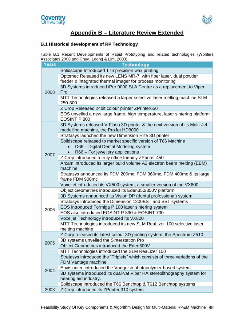
Appendix B – Literature Review Extended B.1 Historical development of RP Technology Table B.1 Recent Developments of Rapid Prototyping and related technologies (Wohlers Associates,2008 and Chua, Leong & Lim, 2003).
Years Technology
2008
Solidscape Introduced T76 precision wax printing
Optomec Released its new LENS MR-7 with fiber laser, dual powder feeder & integrated thermal imager for process monitoring
3D Systems introduced iPro 9000 SLA Centre as a replacement to Viper Pro
MTT Technologies released a larger selective laser melting machine SLM 250-300
Z Crop Released 24bit colour printer ZPrinter650
EOS unveiled a new large frame, high temperature, laser sintering platform EOSINT P 800
2007
3D Systems released V-Flash 3D printer & the next version of its Multi-Jet modelling machine, the ProJet HD3000
Stratasys launched the new Dimension Elite 3D printer
Solidscape released to market specific version of T66 Machine
D66 – Digital Dental Modeling system
R66 – For jewellery applications
Z Crop introduced a truly office friendly ZPrinter 450
Arcam introduced its larger build volume A2 electron beam melting (EBM) machine
Stratasys announced its FDM 200mc, FDM 360mc, FDM 400mc & its large frame FDM 900mc
Voxeljet introduced its VX500 system, a smaller version of the VX800
2006
Object Geometries introduced its Eden350/350V platform
3D Systems announced its Vision DP (dental professional) system
Stratasys introduced the Dimension 1200BST and SST systems
EOS introduced Formiga P 100 laser sintering system
EOS also introduced EOSINT P 390 & EOSINT 730
Voxeljet Technology introduced its VX800
MTT Technologies introduced its new SLM ReaLizer 100 selective laser melting machine
2005
Z Corp released its latest colour 3D printing system, the Spectrum Z510
3D systems unveiled the Sinterstation Pro
Object Geometries introduced the Eden500V
MTT Technologies introduced the SLM ReaLizer 100
2004
Stratasys introduced the “Triplets” which consists of three variations of the FDM Vantage machine
Envisiontec introduced the Vanquish photopolymer based system
3D systems introduced its dual-vat Viper HA stereolithography system for hearing aid industry.
Solidscape introduced the T66 Benchtop & T612 Benchtop systems
2003 Z Crop introduced its ZPrinter 310 system
Feasibility Study Of Key Components & Algorithm Design for Multi-Material RP&M Machine 90
Solidscape introduced its T612 system for making wax patterns for investment castings
3D Systems began to sell its In Nision 3D printer
EOS introduced its EOSINT M 270 direct metal laser sintering machine
Trumpf introduced its TrumaForm LF and TrumaForm DMD 505 machines
2002
Stratasys introduced its Dimension product
Envisiontec GmbH began to sell its prefactory & Bioplotter machines
Solidscape introduced its T66 product
Phenix Systems of France sold its first Phenix 900 System
POM began to sell its direct metal deposition machine
Menix, Co., Ltd. Of Korea introduced its first VLM300 variable lamination machines
2001
Object Geometries began to sell a beta version of its Quadra 3D printer
Stratasys began the commercial shipment of its FDM Titan
Z Crop. Introduced its Z810, a system that prints parts in a 500 x 600 x 400 mm build volume.
Generis GmbH of Germany Commercialised its large GS 1500 system used to produce sand cores and molds for metal castings.
EOS announced its DirectSteel 20-V1 peoduct, a steel based powder consisting of particles 20microns
2000
Sanders Design International developed Rapid ToolMaker (RTM)
Object Geometries of Israel announced Quadra
Precision Optical Manufacturing (POM) announced direct metal deposition (DMD)
ZCorp. introduced its Z402C machine, world’s first commercially available mutli-colour 3D printer
Stratasys introduced Prodigy, a machine that produces parts in ABS plastic
1999
3D Systems introduced:
ThermoJet a faster & less expensive version of Actua 2100
SLA 7000 system
Roders began to sell its controlled metal build-up (CMB) machine
1998
Autostrade introduced its E-DARTS stereolithography system
Optomec commercialised its laser-engineered net shaping (LENS) metal powder system.
1997 AeroMet developed a process called laser additive manufacturing (LAM)
1996
Stratasys introduced the Genisys machine, which used an extrusion process similar to FDM
3D Systems sold its first 3D printer Actua 2100
Z Crop. Launched its Z402 3D printer
BPM Technology sold Personal Modeler 2100 commercially
1995 Japan’s Ushio (now called Unirapid Inc.) sold its first stereolithography machine
1994
Solidscape launched ModelMaker machine
EOS commercialised a EOSINT machine based on laser sintering technology
1993 Soligen commercialised direct shell production casting (DSPC)


![Scanned by CamScanner - · PDF fileDESIGN AND ANALYSIS OF ALGORITHM (New) Sections—A & B Time—Three Hours] ... Write the algorithm to implement backward approach on multistage](https://static.documents.pub/doc/80x56/5abe0d307f8b9ad8278cae36/scanned-by-camscanner-and-analysis-of-algorithm-new-sectionsa-b-timethree.jpg)
