Summary Paper Feasibility Study of Standard Sections for Segmental Prestressed Concrete Box Girder Bridges Felix Kulka Consulting Engineer (At time study was conducted, Mr. Kulka was President of T. Y. Lin International, San Francisco, California) S. J. Thoman Structural Engineer T. Y Lin International San Francisco, California S egmental prestressed concrete box girder bridges were introduced in North America in the late sixties and early seventies, following their suc- cessful entry into the European market during the post World War II recon- struction period. Several bridges of this NOTE: This Summary Paper is a condensation of the results of an investigation commissioned by the Fed- eral Highway Administration on the feasibility of using standard sections for segmental prestressed concrete box girder bridges. The study was initiated in 1980 and completed in July of 1982. The full length report, entitled - Feasibility of Standard Sections for Seg- mental Prestressed Concrete Box Girder Bridges" {FHWA RO-82;024) by F. Kulka, S. J. Thoman, and T. Y. Lin is available from the National Technical In- formation Service, Springfield, Virginia 22161. type, both precast and cast in place, were built successfully in the United States and Canada during this time, and the approximately 70 projects which have been designed to date indicate that the segmental prestressed concrete box girder bridge is a very viable alter- native for medium to long span bridge strictures in North America. At the same time, it is recognized that the design and construction of seg- mental bridges still largely follow prac- tices in Europe and that a closer iden- tification with American construction practice is in order. Standardization of certain aspects of segmental box girder bridges appears to he one way to ex- 54
Transcript
Summary Paper
Feasibility Study ofStandard Sections for
Segmental PrestressedConcrete Box Girder Bridges
Felix KulkaConsulting Engineer(At time study was conducted,Mr. Kulka was President ofT. Y. Lin International,San Francisco, California)
S. J. ThomanStructural Engineer
T. Y Lin InternationalSan Francisco, California
Segmental prestressed concrete boxgirder bridges were introduced in
North America in the late sixties andearly seventies, following their suc-cessful entry into the European marketduring the post World War II recon-struction period. Several bridges of this
NOTE: This Summary Paper is a condensation of theresults of an investigation commissioned by the Fed-eral Highway Administration on the feasibility of usingstandard sections for segmental prestressed concretebox girder bridges. The study was initiated in 1980and completed in July of 1982. The full length report,entitled -Feasibility of Standard Sections for Seg-mental Prestressed Concrete Box Girder Bridges"{FHWA RO-82;024) by F. Kulka, S. J. Thoman, andT. Y. Lin is available from the National Technical In-formation Service, Springfield, Virginia 22161.
type, both precast and cast in place,were built successfully in the UnitedStates and Canada during this time, andthe approximately 70 projects whichhave been designed to date indicatethat the segmental prestressed concretebox girder bridge is a very viable alter-native for medium to long span bridgestrictures in North America.
At the same time, it is recognized thatthe design and construction of seg-mental bridges still largely follow prac-tices in Europe and that a closer iden-tification with American constructionpractice is in order. Standardization ofcertain aspects of segmental box girderbridges appears to he one way to ex-
54
Synopsis
Presents the highlights of a study which investigatedthe feasibility of developing standard sections forsegmental prestressed concrete box girder bridges.The report is based on an extensive survey ofsegmental box girder bridges in the United States andCanada. Recommendations are given for specific itemsthat could be standardized, while also discussing areaswhich might not be appropriate to standardization.
pand their economical use by instillingconfidence among bridge engineersand by producing a cost effectivenessthrough uniformity in design, thuspermitting precasters and contractors toinvest in forms and equipment on abroader basis than is done today.
This report deals with the feasibilityof standardizing segmental prestressedconcrete box girder bridges in theUnited States. The study relied heavilyon a survey of bridge engineers in theUnited States and Canada, which pro-duced valuable information on allbridges of this type. Statistical studieswere conducted to determine correla-tions and uniformity of significant pa-rameters, particularly with respect togeometry.
Analytical design studies, mainly todetermine the economical use of mate-rials, were made to augment the statis-tical analyses. The results wereevaluated both qualitatively and quan-titatively, and an advisory technical re-view committee was formed to reviewthe content of the study and its recom-mendations.
The report takes the position thatstandardization of segmental pre-stressed concrete box girder bridges ispossible and should be initiated. The
specific areas which should be standar-dized are listed and discussed in thereport, as are those which are not cur-rently subject to standardization andthose which are questionable.
Scope of Study
Standardization of highway construc-tion elements is a long-standing prac-tice in the American highway industry.Development of the AASHTO-PCI I-girders is one example; precast con-crete culverts, traffic barriers, and pilesare other examples. It is fairly wellagreed that standardization has meritsin cost savings, reduction of construc-tion time, and improved product qual-ity.
It was felt that for standardization ofbox girder sections to succeed, a uni-form approach should be used in orderto permit bridge engineers to designsuch sections with a sufficient degree ofuniformity and to allow precasters andcontractors to bid and build them asthey would any other advanced type ofstructure.
The object of this study, then, was toconsider all the advantages and disad-vantages of standardization and makeappropriate recommendations for future
PCI JOURNAUSeptember-October 1983 55
development. In doing so, care wastaken not to let standardization limitcompetition, rather, standardizationwas approached with a view towardsexploiting all the alternatives, therebyimproving design and increasing com-petition. The scope of the study in-cluded:
1. An assessment of the state of theart of segmental bridge construc-tion.
2. Development of design constraintsas affected by construction limita-tion s.
3. An analysis of costs and benefits ofstandard sections.
4. Development of specific recom-mendations concerning the feasi-bility of standard sections for seg-mental prestressed concrete boxgirder bridges.
Study ApproachIt was felt essential that the recom-
mendations concerning possible stan-dardization be based on experienceswith existing practices rather than onarbitrary judgments.
Accordingly, a questionnaire con-cerning prestressed concrete segmentalbox girder bridges was sent to bridgeengineers in all states and territoriesplus the provinces of Canada. The sur-vey included bridge site, state of com-pletion, cross section, design and de-tails, construction, costs and other per-tinent information. The response wasexcellent, and the information collectedprovided a good sampling for furtherin-depth studies.
The data obtained were categorizedand statistical studies were made toevaluate significant parameters, leadingto a rational assessment of the state ofthe art of segmental bridge design andconstruction. Analytical studies wereperformed in cases where data were notavailable, permitting the establishmentof qualitative and quantitative relation-ships.
State of the Art ofBox Girder Bridges
Cast-in-place, conventionally formedbox girder bridges had been used inNorth America for many years when, inthe late sixties, segmental box girderconstruction was introduced to thecontinent. This type of structure was aEuropean development of the post-World War II era, when the reconstruc-tion of war-torn European countriesdemanded methods of constructionwhich would overcome the scarcity oflabor and which would produce manystructures in the shortest possible time.The development of cast-in-place seg-mental construction is generally attri-buted to Germany, while precast seg-mental construction is primarily aFrench innovation.
Since the volume of construction waslarge and there was sufficient invest-ment available, the box girder becamepopular even though it is not necessar-ily the most economical section for allconditions. The box girder can, how-ever, safely accommodate spans up to800 ft (244 in) and resist a wide range ofstresses. Furthermore, its resistance totorsion made the box girder particularlysuitable for cantilever construction,which proved to be a good method forrapid construction and for achievinglong spans without the use of falseworkor shoring.
The Lievre River Bridge in Quebec(completed in 1967) was the first pre-cast prestressed segmental bridge builtin North America. This was followedshortly by the Bear River Bridge nearDigby, Nova Scotia. The first majorsegmental box girder bridge in theUnited States was the JFK MemorialCauseway in Corpus Christi, Texas(completed in 1973).
As a result of a fairly active programof promotion, more than 50 segmentalbridges have been constructed in NorthAmerica since that time. Their recordwith respect to economy and successful
56
i d
0 ^ C/
qç/
Hawaiian < a_Islands.'----- -
'I
rte] - _.
f I ^
Koror Babelthaup
Puerto Rico
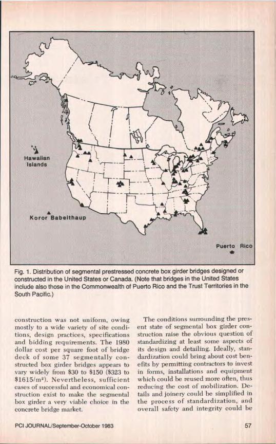
Fig. 1. Distribution of segmental prestressed concrete box girder bridges designed orconstructed in the United States or Canada. (Note that bridges in the United Statesinclude also those in the Commonwealth of Puerto Rico and the Trust Territories in theSouth Pacific.)
construction was not uniform, owingmostly to a wide variety of site condi-tions, design practices, specificationsand bidding requirements. The 1980dollar cost per square foot of bridgedeck of some 37 segmentally con-structed box girder bridges appears tovary widely from $30 to $150 (8323 to$1615/m 2 ). Nevertheless, sufficientcases of successful and economical con-struction exist to make the segmentalbox girder a very viable choice in theconcrete bridge market.
The conditions surrounding the pres-ent state of segmental box girder con-struction raise the obvious question ofstandardizing at least some aspects ofits design and detailing. Ideally, stan-dardization could bring about cost ben-efits by permitting contractors to investin forms, installations and equipmentwhich could be reused more often, thusreducing the cost of mobilization. De-tails and joinery could he simplified inthe process of standardization, andoverall safety and integrity could he
PCI JOUR NAL'September- October 1983 57
ME
15
O V] G Lo 0 0a' (0 P- ti CO CO
r r r r r
Bid Year
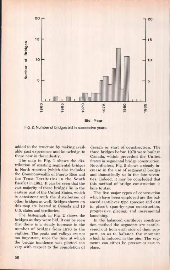
Fig. 2. Number of bridges bid in successive years.
20
15cn
Lm
0 10
L0E7z
added to the structure by making avail-able past experience and knowledge tothose new in the industry.
The map in Fig. 1 shows the dis-tribution of existing segmental bridgesin North America (which also includesthe Commonwealth of Puerto Rico andthe Trust Territories in the SouthPacific) in 1981. It can be seen that thevast majority of these bridges lie in theeastern part of the United States, whichis consistent with the distribution ofother bridges as well. Bridges shown onthis map are located in Canada and 18U.S. states and territories.
The histograph in Fig. 2 shows thebridges as they were hid. It can be seenthat there is a steady increase in thenumber of bridges from 1970 to theeighties. The peaks and valleys are nottoo important, since the time at whichthe bridge incidence was plotted canvary with respect to the completion of
design or start of construction. Thethree bridges before 1970 were built inCanada, which preceded the UnitedStates in segmental bridge construction.Nevertheless, Fig. 2 shows a steady in-crease in the use of segmental bridgesand dramatically so in the late seven-ties. Indeed, it may be concluded thatthis method of bridge construction ishere to stay.
The five major types of constrictionwhich have been employed are the bal-anced cantilever type (precast and castin place), span-by-span construction,progressive placing, and incrementallaunching.
In the balanced cantilever construc-tion method the segments are cantile-vered out from each side of their sup-port, so as to balance the momentwhich is induced in the pier. The seg-ments can either be precast or cast inplace.
58
in progress or completed
35 1- has not been bid or was not selected
30 _QQ. 3 V
2 5 °o° s mU 7C 61 :s Cl
20 a c C Gw a a ro
U l a U V>15 c m I -n tom m m W
E U U
z 10 oC
Construction Method
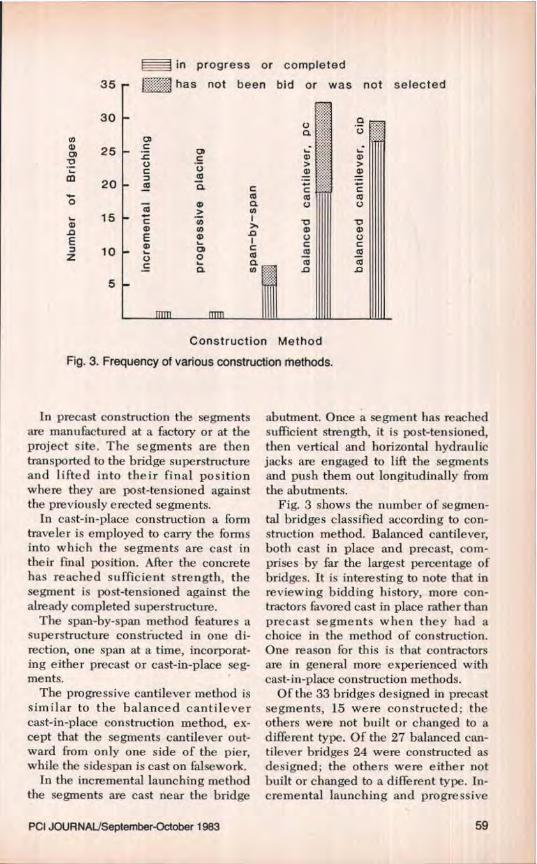
Fig. 3. Frequency of various construction methods.
In precast construction the segmentsare manufactured at a factory or at theproject site. The segments are thentransported to the bridge superstructureand lifted into their final positionwhere they are post-tensioned againstthe previously erected segments.
In cast-in-place construction a formtraveler is employed to carry the formsinto which the segments are cast intheir final position. After the concretehas reached sufficient strength, thesegment is post-tensioned against thealready completed superstructure.
The span-by-span method features asuperstructure constructed in one di-rection, one span at a time, incorporat-ing either precast or cast-in-place seg-ments.
The progressive cantilever method issimilar to the balanced cantilevercast-in-place construction method, ex-cept that the segments cantilever out-ward from only one side of the pier,while the sidespan is cast on falsework.
In the incremental launching methodthe segments are cast near the bridge
abutment. Once a segment has reachedsufficient strength, it is post-tensioned,then vertical and horizontal hydraulicjacks are engaged to lift the segmentsand push them out longitudinally fromthe abutments.
Fig. 3 shows the number of segmen-tal bridges classified according to con-struction method. Balanced cantilever,both cast in place and precast, com-prises by far the largest percentage ofbridges. It is interesting to note that inreviewing bidding history, more con-tractors favored cast in place rather thanprecast segments when they had achoice in the method of construction.One reason for this is that contractorsare in general more experienced withcast-in-place construction methods.
Of the 33 bridges designed in precastsegments, 15 were constructed; theothers were not built or changed to adifferent type. Of the 27 balanced can-tilever bridges 24 were constructed asdesigned; the others were either notbuilt or changed to a different type. In-cremental launching and progressive
PCI JOURNALlSeptember-October 1983 59
;^ in progress or completed4 yw
-has not been bid or was not selected
e 0.09m2 =1.0sf0
d 3- 0.0)a)
m r c m I
Oc2 a
020)— }
ro as
Q
ao
UfbO
_c mdE 0
N U U
IIIIICt0
G^C
ay 1 va
a m MN . p
JC.0)
Construction Method
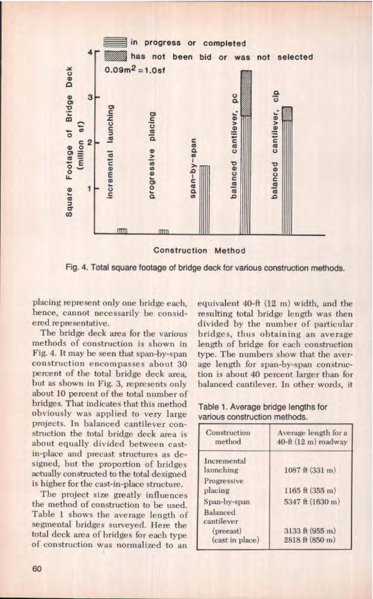
Fig. 4. Total square footage of bridge deck for various construction methods.
placing represent only one bridge each,hence, cannot necessarily be consid-ered representative.
The bridge deck area for the variousmethods of construction is shown inFig, 4. It may be seen that span-by-spanconstruction encompasses about 30percent of the total bridge deck area,but as shown in Fig. 3, represents onlyabout 10 percent of the total number ofbridges. That indicates that this methodobviously was applied to very largeprojects. In balanced cantilever con-struction the total bridge deck area isabout equally divided between cast-in-place and precast structures as de-signed, but the proportion of bridgesactually constructed to the total designedis higher for the cast-in-place structure.
The project size greatly influencesthe method of construction to he used.Table 1 shows the average length ofsegmental bridges surveyed. Here thetotal deck area of bridges .for each typeof construction was normalized to an
equivalent 40-ft (12 m) width, and theresulting total bridge length was thendivided by the number of particularbridges, thus obtaining an averagelength of bridge for each constructiontype. The numbers show that the aver-age length for span-by-span construc-tion is about 40 percent larger than forbalanced cantilever. In other words, it
Table 1. Average bridge lengths forvarious construction methods.
Constructionmethod
Average length for a40-ft (12 m) roadway
Incrementallaunching 1087 ft (331 m)Progressiveplacing 1165 if (355 in)Span-by-span 5347 ft (1630 in)
Balancedcantilever
(precast) 3133 ft (955 m)(cast in place) 2818 ft (850 rn)
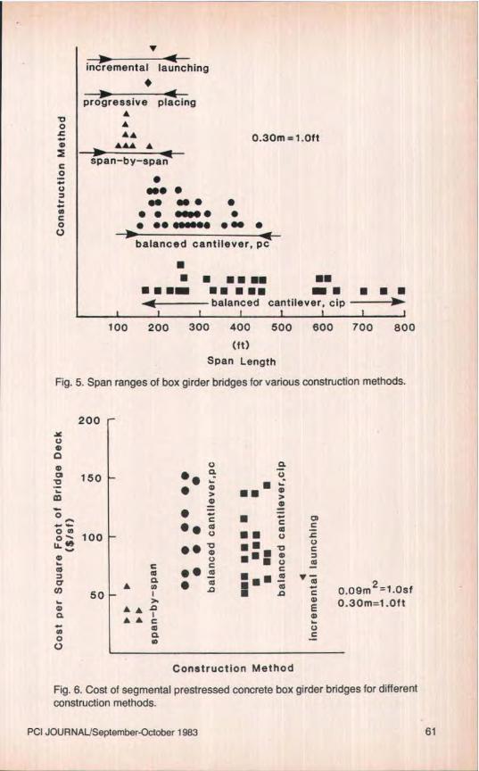
Fig. 5. Span ranges of box girder bridges for various construction methods.
200
Co a
150 •• a °
• C UI
0— 100 •• •• U r
o o
a • e^Q •• •^■ ,,tO
50 • m• • c 0.09m2-1.Osfar ''♦ A m 0.30m=1.OftEa - A
0 a CV
Construction Method
Fig. 6. Cost of segmental prestressed concrete box girder bridges for differentconstruction methods.
PCI JOURNAL/September-October 1983 61
U,a
0 20
aE
Z 10
Cross-Sectional Configuration
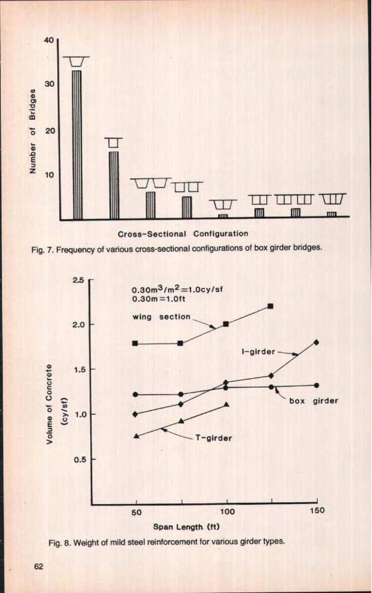
Fig. 7. Frequency of various cross-sectional configurations of box girder bridges.
2.50.30m3/m2=1.Ocy/sf0.30m =1 .Oft
wing section2.0
1.5mnC0U ..wm 7• 1.0E Vv7OJ
rder
0.5
50
100 150
Span Length (ft)
Fig. 8. Weight of mild steel reinforcement for various girder types.
62
2101-cell2-cells ---
1900.30m2/m =1.0sf/ft0.30m= 1.0ft
160 /d
o //0- 130 £(a / A
100 /••
_` W= 70Ar U
7 0 W - 50•
iitEEEE 1iic
W - 30^
40
10 20 30 40(ft)
Girder Depth
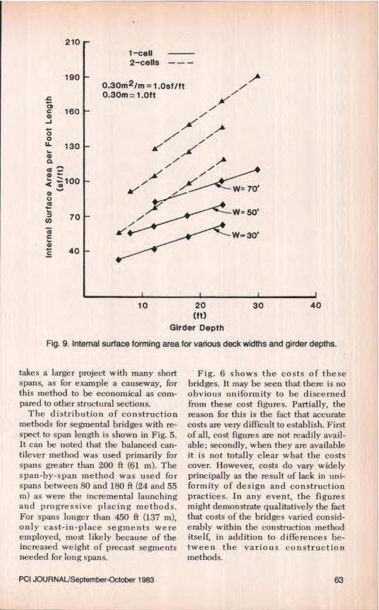
Fig. 9. Internal surface forming area for various deck widths and girder depths.
takes a larger project with many shortspans, as for example a causeway, forthis method to be economical as com-pared to other structural sections.
The distribution of constructionmethods for segmental bridges with re-spect to span length is shown in Fig. 5.It can be noted that the balanced can-tilever method was used primarily forspans greater than 200 ft (61 m). Thespan-by-span method was used forspans between 80 and 180 ft (24 and 55m) as were the incremental launchingand progressive placing methods.For spans longer than 450 ft (137 m),only cast-in-place segments wereemployed, most likely because of theincreased weight of precast segmentsneeded for long spans.
Fig. 6 shows the costs of thesebridges. It may be seen that there is noobvious uniformity to be discernedfrom these cost figures, Partially, thereason for this is the fact that accuratecosts are very difficult to establish. Firstof all, cost figures are not readily avail-able; secondly, when they are availableit is not totally clear what the costscover. However, costs do vary widelyprincipally as the result of lack in uni-formity of design and constructionpractices. In any event, the figuresmight demonstrate qualitatively the factthat costs of the bridges varied consid-erably within the construction methoditself, in addition to differences be-tween the various constructionmethods.
PCI JOURNALISeptember-October 1983 63
1 1 -Cell2 -cells -- -
W=70'10m /
U0
/// W 5O8
E5 ^y W=30'
o>
m= 1.Oft0.300.09m3/m = 1.Ocy /ft
10 20 30 40(t t)
Girder Depth
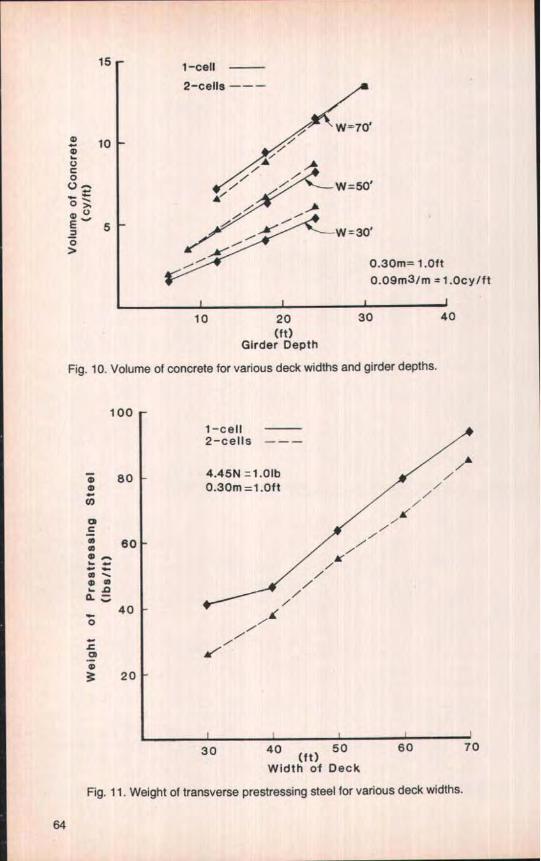
Fig. 10. Volume of concrete for various deck widths and girder depths.
1001 -cell2-cells -----
$0
4.45N =1.01b0.30m -1.0ft
c /m 60of
/
a "40 J(
o /
20
30 40 (ft) 50 60 70
Width of Deck
Fig. 11. Weight of transverse prestressing steel for various deck widths.
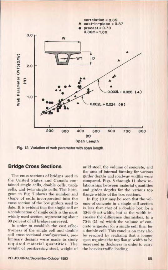
Fig. 12. Variation of web parameter with span length.
Bridge Cross Sections
The cross sections of bridges used inthe United States and Canada con-tained single cells, double cells, triplecells, and twin single cells. The histo-gram in Fig. 7 shows the number andshape of cells incorporated into thecross section of the box girders used todate. It is evident that the single cell ora combination of single cells is the mostwidely used section, representing about90 percent of all bridges surveyed.
In order to establish the cost effec-tiveness of the single cell and doublecell cross-sectional configurations, pre-liminary designs were made to studyrequired material quantities. Theweight of prestressing steel, weight of
mild steel, the volume of concrete, andthe area of internal forming for variousgirder depths and roadway widths werecompared. Figs. 8 through 11 show re-lationships between material quantitiesand girder depths for the various topflange widths of the box sections.
In Fig. 10 it may be seen that the vol-ume of concrete in a single cell sectionis less than that of a double box for a30-ft (9 m) width, but as the width in-creases the difference diminishes. In a70-ft (21 m) width the volume of con-crete is greater for a single cell than fora double cell. This conclusion may alsobe reached by realizing that a longerspan requires the top flange width to beincreased in thickness in order to carrythe heavier traffic loading.
PCI JOURNAUSeptember-October 1983 65
correlation = 0.83W cast-in-place - 0.87
• precast=0.520.30m=1.Oft
....:r ST ♦
l^ vSW /
(A) 0.005L-0.654AL
2.0(DEI-
&
0
0 1.0
tA'
• •
AA
♦•
• • ♦0.003L+0.234 (•)
f
A• •
• ♦N
200 300 400 500 600 700
Span Length (ft)
Fig. 13. Variation of soffit parameter with span length.
4.0 i
3.0
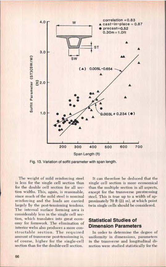
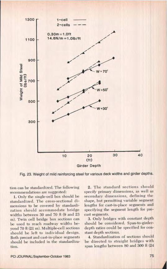
The weight of mild reinforcing steelis less for the single cell section thanfor the double cell section for all sec-tion widths. This, again, is reasonable,since much of the mild steel is nominalreinforcing and the loads are carriedlargely by the post-tensioning tendons.The internal surface forming area isconsiderably less in the single cell sec-tion, which translates into great econ-omy for formwork. The elimination ofinterior webs also produces a more con-structable section. The requiredamount of transverse post-tensioning is,of course, higher for the single-cellsection than for the double-cell section.
It can therefore be deduced that thesingle cell section is more economicalthan the multiple section in all aspects,except for the transverse prestressingsteel. This is true up to a width of ap-proximately 70 ft (21 m), at which pointtwin single cells should be considered.
Statistical Studies ofDimension Parameters
In order to determine the degree ofuniformity in dimensions, parametersin the transverse and longitudinal di-rection were studied statistically for the
66
3•1- CLcorrelation = 0.600.30m =1 .Oft
mm 7> 2.0 • •
• • • 0.064CL + 0.81
1.0
4
0UO
5 10 15 20(ft)
Length of Cantilever
Fig. 14. Variation of cantilever deck thickness with cantilever length.
bridges surveyed. Linear regressioncurves were fitted through the datapoints using a least square criterion.
Correlation coefficients were calcu-lated to determine the uniformity be-tween the parameters. The parameterswith correlation coefficients greaterthan approximately 0.80 were consid-ered to be related, indicating uni-formity. Such uniformity would suggestthat the parameters lend themselves tostandardization. Note that precast andcast-in-place bridges were consideredtogether and also independently.
To study the web dimensions for aparticular span length, the web area forthose bridges surveyed was normalizedby the bridge width. This accounted forthe varied number of traffic lanes andloading conditions. The web parameterwas defined as the total area of the webdivided by the bridge width. The re-lationship between web parameter and
span length is shown in Fig. 12. Thecorrelation coefficient was 0.85 whencombined and 0.87 and 0.70 whenstudied independently for cast-in-placeand precast bridges, respectively.These values indicate uniformity,which suggests the feasibility of stan-dardization.
It is interesting to note that the func-tion for these precast bridges wasbelow and somewhat parallel to cast-in-place bridges. This indicates that forthe same span length the precast seg-ments incorporate thinner webs thantheir cast-in-place equivalents, whichmay be related to weight reductionstrived for in plant production.
The study of the soffit parameter,shown in Fig. 13, was defined by di-viding the soffit cross-sectional area (lo-cated near the pier) by the bridgewidth, which normalized the differentbridges surveyed. Quantitatively, when
PCI JOURNAUSeptemher-October 1983 67
20
7 D
correlation = 0.95A cast-in-place• precast
0.30m=1.Oft
11
15
m0a Z.m0i0 10
0.042L+0.45• slope 1:22 to 1:23
• • ^
••
200 250 300 350 400 450(ft)
Span Length
Fig. 15. Variation of girder depth with span length for balanced cantilever construction.
the structural system is continuous overa support, the bottom soffit near thesupport must develop a compressiveforce to resist the induced moment.Since this induced moment is related tothe span length, the bottom soffit areamust also increase with increasing spanlength. The correlation coefficient con-sidering both precast and cast-in-placesegments was 0.83, indicating good cor-relation.
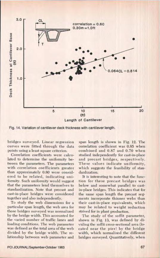
In Fig. 14, the deck thickness at thecantilever base is plotted against thelength of cantilever. The figure repre-sents the results of a study of the deckthickness at the transverse cantileversupport as a function of the cantileverlength. AIthough a low correlationcoefficient of 0.60 was calculated, thedeck thickness could intuitively bestandardized For a particular bridgewidth.
The low correlation may be attri-buted to the varying amount of trans-verse prestressing in the deck, whichwas not included in the study. Also, thedeck thickness of the cantilever at itssupport may he controlled by dimen-sioning requirements to accommodatethe longitudinal tendon anchorages, in-stead of providing the amount of resis-tance to induced forces.
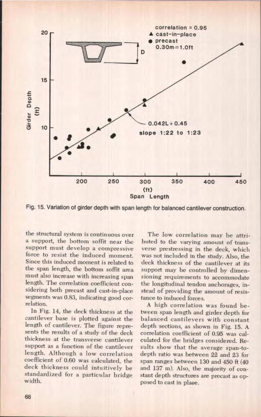
A high correlation was found be-tween span length and girder depth forbalanced cantilevers with constantdepth sections, as shown in Fig. 15. Acorrelation coefficient of 0.95 was cal-culated for the bridges considered. Re-sults show that the average span-to-depth ratio was between 22 and 23 forspan ranges between 130 and 450 ft (40and 137 m). Also, the majority of con-stant depth structures are precast as op-posed to cast in plaee.
correlation50 r A cast-in-place =0.84
• precast =0.600.30m =1.Oft
MIOP L0
0 4.0s
aW
AL
A
L
^ Qa 3.0
c ..a
2
0
2.00a-
-0.004L+O.9 (A)
if • ^
A 0.003E+1.13 (•)
•
300 400 500 600 700 800(ft)
Span Length
Fig. 16. Pier to midspan girder depth ratio for various span lengths for balancedcantilever construction.
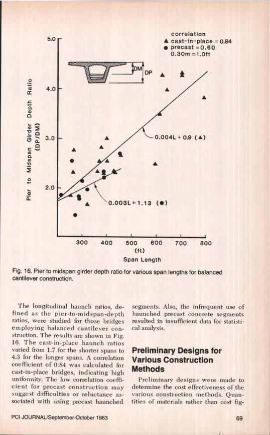
The longitudinal haunch ratios, de-fined as the pier-to-midspan-depthratios, were studied for those bridgesemploying balanced cantilever con-struction. The results are shown in Fig.16. The cast-in-place haunch ratiosvaried from 1.7 for the shorter spans to4.3 for the longer spans. A correlationcoefficient of 0.84 was calculated forcast-in-place bridges, indicating highuniformity. The low correlation coeffi-cient for precast construction maysuggest difficulties or reluctance as-sociated with using precast haunched
segments. Also, the infrequent use ofhaunched precast concrete segmentsresulted in insufficient data for statisti-caI analysis.
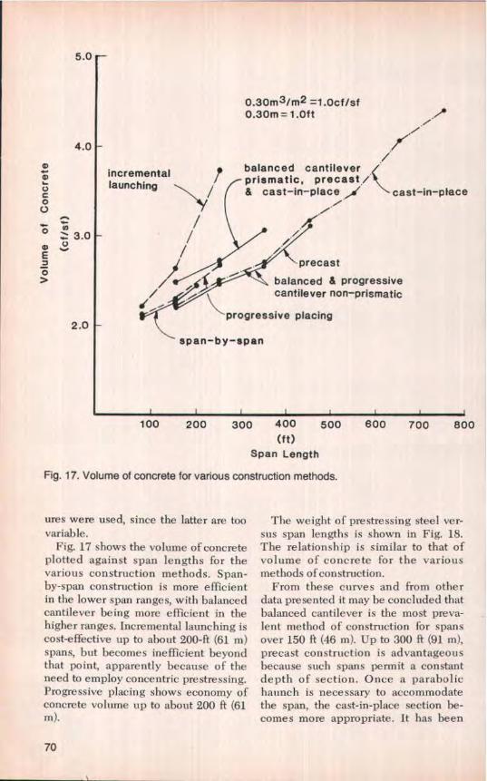
Fig. 17. Volume of concrete for various construction methods.
ures were used, since the latter are toovariable.
Fig. 17 shows the volume of concreteplotted against span lengths for thevarious construction methods. Span-by-span construction is more efficientin the lower span ranges, with balancedcantilever being more efficient in thehigher ranges. Incremental launching iscost-effective up to about 200-ft (61 m)spans, but becomes inefficient beyondthat point, apparently because of theneed to employ concentric prestressing.Progressive placing shows economy ofconcrete volume up to about 200 ft (61m).
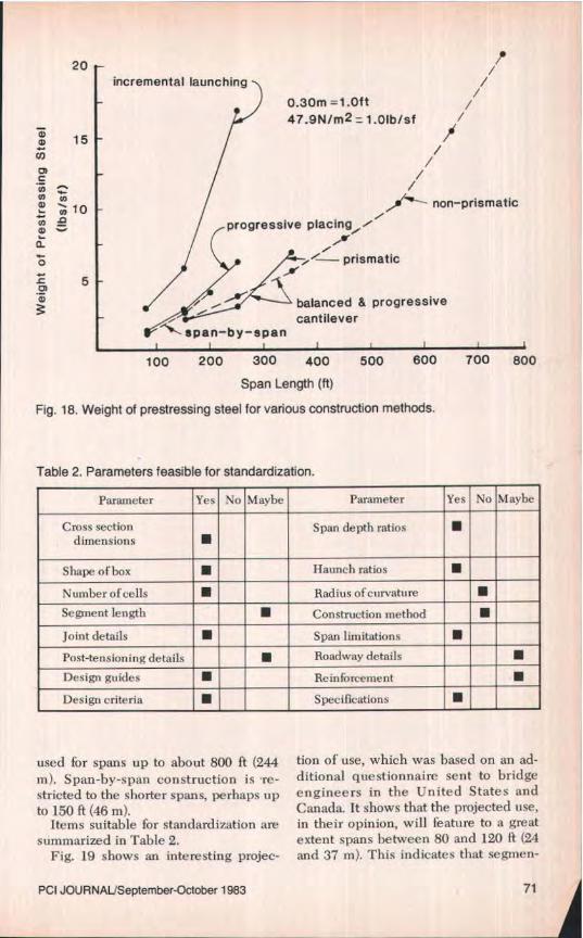
The weight of prestressing steel ver-sus span lengths is shown in Fig. 18.The relationship is similar to that ofvolume of concrete for the variousmethods ofconstnrction.
From these curves and from otherdata presented it may he concluded thatbalanced cantilever is the most preva-lent method of construction for spansover 150 It (46 m). Up to 300 ft (91 m),precast construction is advantageousbecause such spans permit a constantdepth of section. Once a parabolichaunch is necessary to accommodatethe span, the cast-in-place section be-comes more appropriate. It has been
70
20incremental launching
0.30m =1 Oft47.9NJm2=1.Olb/sf
15/
/N ^^ /5,
non–prismatic1fl progressive placing-''
^! prismatico
L 5 ^'
balanced & progressivea,
cantileverti- span-by-span
100 200 300 400 500 600 700 800
Span Length (ft)
Fig. 18. Weight of prestressing steel for various construction methods.
Table 2. Parameters feasible for standardization.
Parameter Yes No Maybe Parameter Yes No Maybe
Cross sectiondimensions ■
Span depth ratios ■
Shape of box • Haunch ratios ■
Number of cells ■ Radius ofcurvature ■Segment length ■ Construction method ■Joint details ■ Span limitations ■
used for spans up to about 800 ft (244m). Span-by-span construction is 're-stricted to the shorter spans, perhaps upto 150 ft (46 in).
Items suitable for standardization aresummarized in Table 2.
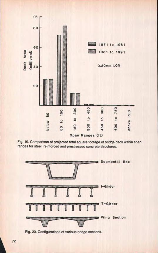
Fig. 19 shows an interesting projec-
tion of use, which was based on an ad-ditional questionnaire sent to bridgeengineers in the United States andCanada, It shows that the projected use,
in their opinion, will feature to a greatextent spans between 80 and 120 ft (24and 37 m). This indicates that segmen-
PCI JOURNAUSeptember-October 1983 71
95
80
60m r,m ^^ c0
=E40o
20
o 0 0 00 o o MD o
0 Ui 4 W u]N
o o 0 0
0 0 0 0 0 0'CD 0 IL) o MD aa m r c*) V W m
Span Ranges (ft)
Fig. 19. Comparison of projected total square footage of bridge deck within spanranges for steel, reinforced and prestressed concrete structures.
Fig. 20. Configurations of various bridge sections.
72
1247.9Nlm2=1.Olb/sf0.30m =1.Oft
10
wing section
81-girder
C
^ a 6o ^. box girderzas
4 -T-girder
2
50
100 150(ft)
Span Length
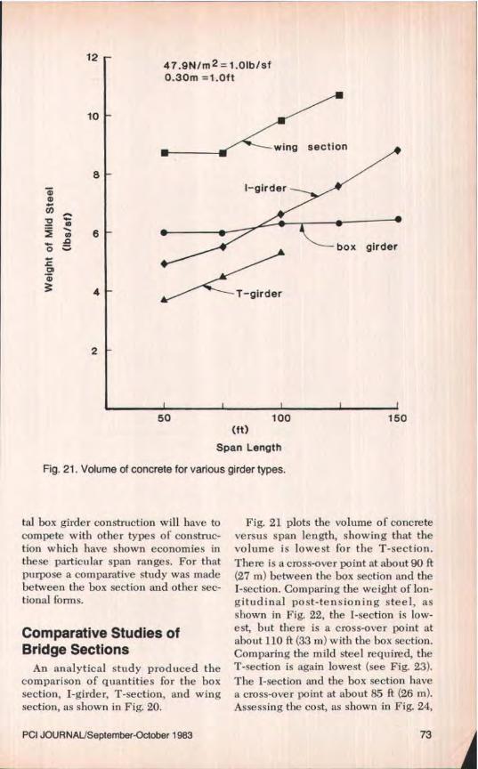
Fig. 21, Volume of concrete for various girder types.
tal box girder construction will have tocompete with other types of construc-tion which have shown economies inthese particular span ranges. For thatpurpose a comparative study was madebetween the box section and other sec-tional forms.
Comparative Studies ofBridge Sections
An analytical study produced thecomparison of quantities for the boxsection, I-girder, T-section, and wingsection, as shown in Fig. 20.
PCI JOUR NAL/September-October 1983
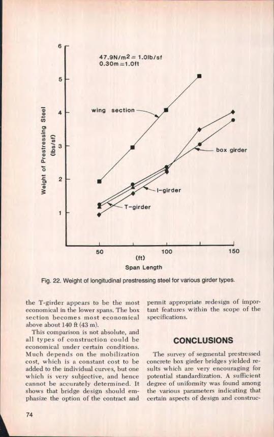
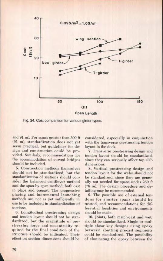
Fig. 21 plots the volume of concreteversus span length, showing that thevolume is lowest for the T-section,There is a cross-over point at about 90 ft(27 m) between the box section and theI-section. Comparing the weight of lon-gitudinal post-tensioning steel, asshown in Fig. 22, the I-section is low-est, but there is a cross-over point atabout 110 ft (33 m) with the box section.Comparing the mild steel required, theT-section is again lowest (see Fig. 23).The I-section and the box section havea cross-over point at about 85 ft (26 m).Assessing the cost, as shown in Fig, 24,
73
47.9N/m2= 1.0lbisf0.30m=1.Oft
6
5
4 w
N N
- m 3N ^Q)
5-
0.c 2a)
rder
50 100 150(ft)
Span Length
Fig. 22. Weight of longitudinal prestressing steel for various girder types.
the T-girder appears to be the mosteconomical in the lower spans. The boxsection becomes most economicalabove about 140 ft (43 m).
This comparison is not absolute, andall types of construction could beeconomical under certain conditions.Much depends on the mobilizationcost, which is a constant cost to beadded to the individual curves, but onewhich is very subjective, and hencecannot be accurately determined. Itshows that bridge design should em-phasize the option of the contract and
permit appropriate redesign of impor-tant features within the scope of thespecifications.
CONCLUSIONSThe survey of segmental prestressed
concrete box girder bridges yielded re-sults which are very encouraging forpotential standardization. A sufficientdegree of uniformity was found amongthe various parameters indicating thatcertain aspects of design and construe-
74
1300 1-cell2 -cells — — —
0.30m=t.Oft A/
1100 14.6N/m =1.01b/ftA/
f
A/
900 Aj A&
m u1 W = 70`
m 700 l/o ^ /s A / W = 50'
500 f/
300
10 20 30 40(ft)
Girder Depth
Fig. 23. Weight of mild reinforcing steel for various deck widths and girder depths.
tion can be standardized. The followingrecommendations are suggested:
1. Only the single-cell box should bestandardized. The cross-sectional di-mensions to be covered by standardi-zation should accommodate bridgewidths between 30 and 70 ft (9 and 23m). Twin cell bridge box sections canbe used to reach roadway widths be-yond 70 ft (21 m). Multiple—cell sectionsshould be left to individual design.Both precast and cast-in-place segmentsshould he included in the standardiza-tion.
2. The standard sections shouldspecify primary dimensions, as well assecondary dimensions, defining theshape, but permitting variable segmentlengths for cast-in-place segments andspecifying the segment length for pre-cast segments.
3. Only bridges with constant depthshould he considered. Span-to-girder-depth ratios could be specified for con-stant depth sections.
4. Standardization of sections shouldbe directed to straight bridges withspan lengths between 80 and 300 ft (24
PCI JOURNAL/September- October 1983 75
400.09$/m2=1.0$/sf
30 r wing section
w NoU ^
20box girde I—girder
T—girder10
50
100
150
(ft)Span Length
Fig. 24. Cost comparison for various girder types.
and 91 m). For spans greater than 300 ft(91 m), standardization does not yetseem practical, but guidelines for de-sign and construction could be pro-vided. Similarly, recommendations forthe accommodation of curved bridgesshould be included.
5. Construction methods themselvesshould not he standardized, but thestandardization of sections should con-sider the balanced cantilever methodand the span-by-span method, both castin place and precast. The progressiveplacing and incremental launchingmethods are not as yet sufficiently inuse to be included in standardization ofsections.
6. Longitudinal prestressing designand tendon layout should not be stan-dardized, but the magnitude of pre-stressing force and eccentricity re-quired for the final condition of thestructure should be indicated. Theireffect on section dimensions should be
considered, especially in conjunctionwith the transverse prestressing tendonlayout in the deck.
7. Transverse prestressing design andtendon layout should be standardized,since they can seriously affect top slabdimensions.
8. Vertical prestressing design andtendon layout for the webs should notbe standardized, since they are gener-ally not needed fbr spans under 250 ft(76 in). The design procedure and de-tailing may he recommended.
9. The possible use of external ten-dons for shorter spans should betreated, and recommendations fbr dif-ferential localities and environmentsshould be made.
10. Joints, both match-cast and wet,should be standardized. Single or mul-tiple shear key designs using epoxybetween abutting precast segmentscould be standardized. The possibilityof eliminating the epoxy between the
76
precast segments should be studiedfurther.
11. Typical designs of anchorages andblisters for continuity and cap tendonsmay be suggested, but not standar-dized.
12. The use of bonded mild steel re-inforcement for partial prestressing,temperature and shrinkage control,stress concentration, prevention of de-lamination, and other local problemsmay be recommended.
13. Design of sidewalks, bicyclepaths, barriers, and railings should notbe standardized.
14. Deflection control, both duringconstruction and after completion,should he taken into account in the di-mensioning of standard sections.
15. Location of expansion joints, bothtemporary and permanent, may affectthe design of standard sections, andguidelines should be established.
16. Uniformity in design and specifi-cations should be addressed.
It would be very desirable, indeed, ifstandardization of segmental pre-stressed concrete box girder bridgescould be accomplished to the same de-gree as AASHTO I-girders. The ap-proach could certainly be similar to thatof the I-girders, inasmuch as dimen-sional standards and construction prac-tices could he made uniform,
The extent to which such standardi-
zation could be carried out is not asclear in the case of box girder bridges,given their complexity, difference inconstruction methods, span ranges, andother variables. In any event, stan-dardization should be done to enhancethe use of segmental bridges by design-ers and contractors, but it should beconceived and applied so as not to im-pede new developments which mightbring about greater economy, highersafety and better performance.
ACKNOWLEDGMENT
This investigation was sponsored bythe Office of Research and Develop-ment, Federal Highway Administration,U.S. Department of Transportation,Washington, D.C., under the directionof Thomas Krylowski and Craig A. Bal-linger.
The authors wish to thank theFHWA's technical review committeefor help and guidance throughout thestudy and preparation of the report.Members included Thomas Alberdi,John Breen, Clifford Freyermuth,Wayne Henneberger, Jerry Jacques andGordon Ray. The authors also wish toexpress their appreciation to the bridgeengineers in the United States andCanada for the information they pro-vided in the bridge survey question-naire.
NOTE: Discussion of this paper is invited. Please submityour comments to PCI Headquarters by May 1, 1984.